EP1428693B1 - Transponder for tire condition monitoring apparatus - Google Patents
Transponder for tire condition monitoring apparatusDownload PDFInfo
- Publication number
- EP1428693B1 EP1428693B1EP03026127AEP03026127AEP1428693B1EP 1428693 B1EP1428693 B1EP 1428693B1EP 03026127 AEP03026127 AEP 03026127AEP 03026127 AEP03026127 AEP 03026127AEP 1428693 B1EP1428693 B1EP 1428693B1
- Authority
- EP
- European Patent Office
- Prior art keywords
- transponder
- tire
- coil antenna
- condition
- monitoring apparatus
- Prior art date
- Legal status (The legal status is an assumption and is not a legal conclusion. Google has not performed a legal analysis and makes no representation as to the accuracy of the status listed.)
- Expired - Lifetime
Links
- 238000012544monitoring processMethods0.000titleclaimsdescription14
- 230000005611electricityEffects0.000claimsdescription15
- 230000004044responseEffects0.000claimsdescription5
- 238000000034methodMethods0.000description3
- 238000010586diagramMethods0.000description2
- 238000004073vulcanizationMethods0.000description2
- 230000005856abnormalityEffects0.000description1
- 230000005540biological transmissionEffects0.000description1
- 238000004891communicationMethods0.000description1
- 238000001514detection methodMethods0.000description1
- 230000005672electromagnetic fieldEffects0.000description1
- 230000006870functionEffects0.000description1
- 230000001771impaired effectEffects0.000description1
- WABPQHHGFIMREM-UHFFFAOYSA-Nlead(0)Chemical compound[Pb]WABPQHHGFIMREM-UHFFFAOYSA-N0.000description1
- 238000005259measurementMethods0.000description1
- 238000012545processingMethods0.000description1
Images


Classifications
- B—PERFORMING OPERATIONS; TRANSPORTING
- B60—VEHICLES IN GENERAL
- B60C—VEHICLE TYRES; TYRE INFLATION; TYRE CHANGING; CONNECTING VALVES TO INFLATABLE ELASTIC BODIES IN GENERAL; DEVICES OR ARRANGEMENTS RELATED TO TYRES
- B60C23/00—Devices for measuring, signalling, controlling, or distributing tyre pressure or temperature, specially adapted for mounting on vehicles; Arrangement of tyre inflating devices on vehicles, e.g. of pumps or of tanks; Tyre cooling arrangements
- B60C23/02—Signalling devices actuated by tyre pressure
- B60C23/04—Signalling devices actuated by tyre pressure mounted on the wheel or tyre
- B60C23/0408—Signalling devices actuated by tyre pressure mounted on the wheel or tyre transmitting the signals by non-mechanical means from the wheel or tyre to a vehicle body mounted receiver
- B—PERFORMING OPERATIONS; TRANSPORTING
- B60—VEHICLES IN GENERAL
- B60C—VEHICLE TYRES; TYRE INFLATION; TYRE CHANGING; CONNECTING VALVES TO INFLATABLE ELASTIC BODIES IN GENERAL; DEVICES OR ARRANGEMENTS RELATED TO TYRES
- B60C23/00—Devices for measuring, signalling, controlling, or distributing tyre pressure or temperature, specially adapted for mounting on vehicles; Arrangement of tyre inflating devices on vehicles, e.g. of pumps or of tanks; Tyre cooling arrangements
- B60C23/02—Signalling devices actuated by tyre pressure
- B60C23/04—Signalling devices actuated by tyre pressure mounted on the wheel or tyre
- B60C23/0491—Constructional details of means for attaching the control device
- B60C23/0494—Valve stem attachments positioned inside the tyre chamber
Definitions
- the present inventionrelates to a transponder according to the preamble of claim 1 and being provided for a tire condition monitoring apparatus that wirelessly transmits data representing the condition of a tire in response to radio waves having a field intensity equal to or greater than a predetermined level.
- transponderis described in US-A-5987980, US-A-5853020 or WO-02/20287A1.
- Japanese Laid-Open Patent Publication No. 5-169931discloses a tire having a transponder.
- the transponderhas a coil antenna for wirelessly transmitting the condition of the tire attached to a vehicle.
- electricityis induced by the coil antenna.
- the transponderwirelessly transmits data representing, for example, identification of the tire.
- the transponder of the publicationis accommodated in a tire, the transponder is changed when the tire is replaced by a new tire.
- the new tiremust have the same type of transponder, the choices of tire are limited. Also, to process the removed tire, the accommodated transponder must be removed, which creates an additional work. That is, the transponder cannot be separated from the tire main body. This adds to inconvenience when replacing and scrapping the tire.
- transponderfor tire condition monitoring apparatus, which transponder can be separated from a tire main body.
- a transponder for a tire condition monitoring apparatusis provided according to claim 1.
- the tire condition monitoring apparatusdetects condition of a tire and wirelessly transmits data representing the detected condition in response to radio waves having a field intensity equal to or greater than a predetermined level.
- the transponderis provided in a tire valve.
- a tire condition monitoring apparatus 1according to one embodiment will now be described with reference to the drawings.
- the apparatus 1is used in a vehicle such as an automobile.
- the tire condition monitoring apparatus 1includes four transponders 30 and a transmitter-receiver 40.
- Each transponder 30is located in one of the tires 20 of a vehicle 10.
- the transmitter-receiver 40is located on a body frame 11 of the vehicle 10.
- Each transponder 30is located in the corresponding tire 20 and is fixed, for example, to a wheel 21 of the tire 20. Each transponder 30 measures the condition of the corresponding tire 20, that is, the pressure of the tire 20. The transponder 30 then wirelessly transmits data containing air pressure data.
- the transmitter-receiver 40is located at a predetermined position on the body frame 11 and is activated by electricity of a battery (not shown) of the vehicle 10.
- the transmitter-receiver 40has four antennas 41, each of which corresponds to different one of the transponders 30. Each antenna 41 is connected to the transmitter-receiver 40 with a cable 42.
- the transmitter-receiver 40transmits radio waves having a field intensity equal to or greater than a predetermined level at a predetermined timing. Based on the radio waves, each transponder 30 induces electricity for wirelessly transmitting data containing pressure data.
- the transmitter-receiver 40receives data transmitted by each transponder 30 chiefly through the corresponding antenna 41.
- a display 50is located in the view of the driver of the vehicle 10, for example, in the passenger compartment.
- the display 50is connected to the transmitter-receiver 40 with a cable 43.
- each transponder 30includes a controller 31, which is a microcomputer.
- the controller 31includes, for example, a central processing unit (CPU), a read only memory (ROM), and a random access memory (RAM).
- a unique ID codeis registered in an internal memory, for example, the ROM, of the controller 31. The ID code is used to distinguish the associated transponder 30 from the other three transponders 30.
- Each pressure sensor 32measures the air pressure in the interior of the associated tire 20 and provides the controller 31 with pressure data, which is obtained from the measurement. Each pressure sensor 32 functions as condition detecting means.
- Each controller 31sends data containing the air pressure data and the registered ID code to a transmission-reception circuit 33.
- the transmission-reception circuit 33encodes and modulates the data sent from the controller 31.
- the transmission-reception circuit 33then wirelessly sends the data through the coil antenna 34.
- the coil antenna 34induces electricity in response to radio waves having a field intensity equal to or greater than a predetermined level. For example, in response to radio waves transmitted by the corresponding antenna 41, the coil antenna 34 induces electricity.
- the transmission-reception circuit 33supplies the induced electricity to the controller 31.
- the controller 31controls the transponder 30 with the supplied electricity. In other words, the transponder 30 is activated with the electricity induced by the coil antenna 34.
- the controller 31 and the transmission-reception circuit 33are integrated on a single IC 35.
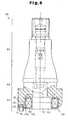
- a tire valve 60includes an upper portion 61 protruding outward from the wheel 21, an engage portion 62 engaged with a valve hole of the wheel 21, and a lower portion 63 embedded in the tire 20.
- the tire valve 60is a "snap-in valve (covered with rubber)".
- the transponder 30is located at the lower portion 63 of the tire valve 60. That is, the transponder 30 is accommodated in substantially annular upper and lower cases 71, 72 in the lower portion 63 of the tire valve 60.
- the cases 71, 72include an annular portion 73 accommodating the annular coil antenna 34, and a projection portion 74 accommodating the IC 35 and the pressure sensor 32.
- Annular magnetic plates 81, 82are provided on the outer circumference and the inner circumference of the coil antenna 34, respectively.
- the magnetic plates 81, 82permit the coil antenna 34 to generate a high voltage.
- the magnetic plates 81, 82also permit the directivity of the coil antenna 34 to be controlled.
- a hole 75is formed in the projection portion 74 of the lower case 72.
- the pressure sensor 32is provided in a portion of the projection portion 74 that corresponds to the hole 75.
- the pressure sensor 32measures the air pressure in the tire 20 through the hole 75.
- the pressure sensor 32is connected to the IC 35 with a lead wire 36.
- the IC 35is connected to the coil antenna 34 with the coil terminals 34a, 34b of the coil antenna 34.
- the transmitter-receiver 40includes a controller 44 and a transmission-reception circuit 45.
- the transmission-reception circuit 45processes data received with the antennas 41.
- the controller 44which is, for example, a microcomputer, includes a CPU, a ROM, and a RAM.
- the transmission-reception circuit 45receives data transmitted by each transponder 30 chiefly through the corresponding antenna 41.
- the transmission-reception circuit 45demodulates and decodes the received data and sends the data to the controller 44.
- the controller 44Based on the received data, the controller 44 obtains the internal pressure of the tire 20 that is associated with the transponder 30 that is the source of the received data. The controller 44 also causes the display 50 to show data regarding the air pressure. Particularly, when there is an abnormality in the pressure of the tire 20, the reception controller 44 displays warning on the display 50.
- the controller 44causes the antennas 41 to transmit radio waves having a field intensity equal to or greater than a predetermined level at a predetermined timing. Based on the radio waves, the coil antenna 34 of each transponder 30 induces electricity. The transponder 30 uses the electricity to wirelessly transmit data containing the air pressure data. The transmitter-receiver 40 receives data transmitted by each transponder 30 chiefly through the corresponding antenna 41.
- the coil antenna 34 of the transponder 30 that corresponds to the antenna 41induces electricity.
- the induced electricitypermits the transponder 30 to measure the air pressure in the tire 20 with the pressure sensor 32.
- the transponder 30wirelessly transmits data containing the data of the measured air pressure with the coil antenna 34.
- the transmitter-receiver 40receives data wirelessly transmitted by the transponder 30 through the corresponding reception antenna 41. Based on the received data, the transmitter-receiver 40 obtains the air pressure of the tire 20 that is associated with the transponder 30 that is the source of the received data.
- the transmitter-receiver 40also causes the display 50 to show data regarding the air pressure.
- This embodimenthas the following advantages.
- annular magnetic plates 91, 92may be provided on the axial end faces of each coil antenna 34.
- the magnetic plates 91, 92have substantially the same outer diameter as the coil antenna 34. That is, the magnetic plates 91, 92 may be provided between the upper case 71 and the upper side of the coil antenna 34, and between the lower case 72 and the lower side of the coil antenna 34, respectively.
- the magnetic plates 91, 92permit the coil antenna 34 to generate a high voltage.
- the magnetic plates 91, 92also permit the directivity of the coil antenna 34 to be controlled.
- each coil antenna 34is a nondirectional antenna.
- each coil antenna 34may be changed.
- each coil antenna 34may be shaped as an ellipse or a polygon.
- each transponder 30may have another condition detection means such as a temperature sensor for measuring the temperature in the tire 20.
- the transponder 30wirelessly transmits the temperature data in the tire 20.
- Air pressure data transmitted by each transponder 30may indicate the value of the air pressure or whether the air pressure is within a permissible range.
- the present inventionmay be applied to two-wheeled vehicles, such as bicycles and motor cycles, multi-wheeled busses, multi-wheeled towed vehicles and industrial vehicles, such as forklifts.
- the transmitter-receiver 40 and the display 50are provided in the tractor.
- the cases 71, 72which are located in the lower portion 63 of the tire valve 60, may be adhered to each other through vulcanization.
- a space for the transponder 30may be created in the lower portion 63 of the tire valve 60, and, thereafter, the cases 71, 72 may be provided in the created space.
Landscapes
- Engineering & Computer Science (AREA)
- Mechanical Engineering (AREA)
- Measuring Fluid Pressure (AREA)
- Arrangements For Transmission Of Measured Signals (AREA)
Description
- The present invention relates to a transponder according to the preamble of
claim 1 and being provided for a tire condition monitoring apparatus that wirelessly transmits data representing the condition of a tire in response to radio waves having a field intensity equal to or greater than a predetermined level. - Such transponder is described in US-A-5987980, US-A-5853020 or WO-02/20287A1. Japanese Laid-Open Patent Publication No. 5-169931 discloses a tire having a transponder. The transponder has a coil antenna for wirelessly transmitting the condition of the tire attached to a vehicle. When an interrogating electromagnetic field is generated outside the transponder, electricity is induced by the coil antenna. Based on the induced electricity, the transponder wirelessly transmits data representing, for example, identification of the tire.
- However, since the transponder of the publication is accommodated in a tire, the transponder is changed when the tire is replaced by a new tire.
- Further, since the new tire must have the same type of transponder, the choices of tire are limited. Also, to process the removed tire, the accommodated transponder must be removed, which creates an additional work. That is, the transponder cannot be separated from the tire main body. This adds to inconvenience when replacing and scrapping the tire.
- Accordingly, it is an objective of the present invention to provide a transponder for tire condition monitoring apparatus, which transponder can be separated from a tire main body.
- To achieve the foregoing and other objectives and in accordance with the purpose of the present invention, a transponder for a tire condition monitoring apparatus is provided according to
claim 1. The tire condition monitoring apparatus detects condition of a tire and wirelessly transmits data representing the detected condition in response to radio waves having a field intensity equal to or greater than a predetermined level. The transponder is provided in a tire valve. - Other aspects and advantages of the invention will become apparent from the following description, taken in conjunction with the accompanying drawings, illustrating by way of example the principles of the invention.
- The invention, together with objects and advantages thereof, may best be understood by reference to the following description of the presently preferred embodiments together with the accompanying drawings in which:
- Fig. 1 is a diagrammatic view illustrating a tire condition monitoring apparatus;
- Fig. 2 is a block diagram showing a transponder of the tire condition monitoring apparatus of Fig. 1;
- Fig. 3 is a partially cross-sectional view showing the tire valve of the tire condition monitoring apparatus of Fig. 1;
- Fig. 4 is a bottom view showing the tire valve of Fig. 3;
- Fig. 5 is a block diagram showing a transmitter-receiver of the tire condition monitoring apparatus of Fig. 1; and
- Fig. 6 is a partially cross-sectional view showing a tire valve according to another embodiment.
- A tire
condition monitoring apparatus 1 according to one embodiment will now be described with reference to the drawings. Theapparatus 1 is used in a vehicle such as an automobile. - As shown in Fig. 1, the tire
condition monitoring apparatus 1 includes fourtransponders 30 and a transmitter-receiver 40. Eachtransponder 30 is located in one of thetires 20 of avehicle 10. The transmitter-receiver 40 is located on abody frame 11 of thevehicle 10. - Each
transponder 30 is located in thecorresponding tire 20 and is fixed, for example, to awheel 21 of thetire 20. Eachtransponder 30 measures the condition of thecorresponding tire 20, that is, the pressure of thetire 20. Thetransponder 30 then wirelessly transmits data containing air pressure data. - The transmitter-
receiver 40 is located at a predetermined position on thebody frame 11 and is activated by electricity of a battery (not shown) of thevehicle 10. The transmitter-receiver 40 has fourantennas 41, each of which corresponds to different one of thetransponders 30. Eachantenna 41 is connected to the transmitter-receiver 40 with acable 42. The transmitter-receiver 40 transmits radio waves having a field intensity equal to or greater than a predetermined level at a predetermined timing. Based on the radio waves, eachtransponder 30 induces electricity for wirelessly transmitting data containing pressure data. The transmitter-receiver 40 receives data transmitted by eachtransponder 30 chiefly through thecorresponding antenna 41. - A
display 50 is located in the view of the driver of thevehicle 10, for example, in the passenger compartment. Thedisplay 50 is connected to the transmitter-receiver 40 with acable 43. - As shown in Fig. 2, each
transponder 30 includes acontroller 31, which is a microcomputer. Thecontroller 31 includes, for example, a central processing unit (CPU), a read only memory (ROM), and a random access memory (RAM). A unique ID code is registered in an internal memory, for example, the ROM, of thecontroller 31. The ID code is used to distinguish theassociated transponder 30 from the other threetransponders 30. - Each
pressure sensor 32 measures the air pressure in the interior of the associatedtire 20 and provides thecontroller 31 with pressure data, which is obtained from the measurement. Eachpressure sensor 32 functions as condition detecting means. Eachcontroller 31 sends data containing the air pressure data and the registered ID code to a transmission-reception circuit 33. The transmission-reception circuit 33 encodes and modulates the data sent from thecontroller 31. The transmission-reception circuit 33 then wirelessly sends the data through thecoil antenna 34. - The
coil antenna 34 induces electricity in response to radio waves having a field intensity equal to or greater than a predetermined level. For example, in response to radio waves transmitted by thecorresponding antenna 41, thecoil antenna 34 induces electricity. The transmission-reception circuit 33 supplies the induced electricity to thecontroller 31. Thecontroller 31 controls thetransponder 30 with the supplied electricity. In other words, thetransponder 30 is activated with the electricity induced by thecoil antenna 34. Thecontroller 31 and the transmission-reception circuit 33 are integrated on asingle IC 35. - As shown in Figs. 3 and 4, a
tire valve 60 includes anupper portion 61 protruding outward from thewheel 21, an engageportion 62 engaged with a valve hole of thewheel 21, and alower portion 63 embedded in thetire 20. Thetire valve 60 is a "snap-in valve (covered with rubber)". - The
transponder 30 is located at thelower portion 63 of thetire valve 60. That is, thetransponder 30 is accommodated in substantially annular upper andlower cases lower portion 63 of thetire valve 60. Specifically, thecases annular portion 73 accommodating theannular coil antenna 34, and aprojection portion 74 accommodating theIC 35 and thepressure sensor 32. - Annular
magnetic plates coil antenna 34, respectively. Themagnetic plates coil antenna 34 to generate a high voltage. Themagnetic plates coil antenna 34 to be controlled. - A
hole 75 is formed in theprojection portion 74 of thelower case 72. Thepressure sensor 32 is provided in a portion of theprojection portion 74 that corresponds to thehole 75. Thepressure sensor 32 measures the air pressure in thetire 20 through thehole 75. - The
pressure sensor 32 is connected to theIC 35 with alead wire 36. TheIC 35 is connected to thecoil antenna 34 with thecoil terminals coil antenna 34. - As shown in Fig. 5, the transmitter-
receiver 40 includes acontroller 44 and a transmission-reception circuit 45. The transmission-reception circuit 45 processes data received with theantennas 41. Thecontroller 44, which is, for example, a microcomputer, includes a CPU, a ROM, and a RAM. The transmission-reception circuit 45 receives data transmitted by eachtransponder 30 chiefly through the correspondingantenna 41. The transmission-reception circuit 45 demodulates and decodes the received data and sends the data to thecontroller 44. - Based on the received data, the
controller 44 obtains the internal pressure of thetire 20 that is associated with thetransponder 30 that is the source of the received data. Thecontroller 44 also causes thedisplay 50 to show data regarding the air pressure. Particularly, when there is an abnormality in the pressure of thetire 20, thereception controller 44 displays warning on thedisplay 50. - The
controller 44 causes theantennas 41 to transmit radio waves having a field intensity equal to or greater than a predetermined level at a predetermined timing. Based on the radio waves, thecoil antenna 34 of eachtransponder 30 induces electricity. Thetransponder 30 uses the electricity to wirelessly transmit data containing the air pressure data. The transmitter-receiver 40 receives data transmitted by eachtransponder 30 chiefly through the correspondingantenna 41. - An operation of the tire
condition monitoring apparatus 1 configured as above will now be described. - When the transmitter-
receiver 40 outputs radio waves having a field intensity equal to or greater than a predetermined level from eachantenna 41 at a predetermined timing, thecoil antenna 34 of thetransponder 30 that corresponds to theantenna 41 induces electricity. The induced electricity permits thetransponder 30 to measure the air pressure in thetire 20 with thepressure sensor 32. Thetransponder 30 wirelessly transmits data containing the data of the measured air pressure with thecoil antenna 34. The transmitter-receiver 40 receives data wirelessly transmitted by thetransponder 30 through thecorresponding reception antenna 41. Based on the received data, the transmitter-receiver 40 obtains the air pressure of thetire 20 that is associated with thetransponder 30 that is the source of the received data. The transmitter-receiver 40 also causes thedisplay 50 to show data regarding the air pressure. - This embodiment has the following advantages.
- (1) Each
transponder 30 is located at thelower portion 63 of thecorresponding tire valve 60 that is fixed to thewheel 21. Therefore, when the tire is replaced by a new tire, thewheel 21 continues to be used. Thus, thetransponder 30 is not replaced. Also, since thetransponder 30 is located in thetire valve 60, the selection of thetire 20 is not limited. When removing theold tire 20, it is sufficient to remove theold tire 20 from thewheel 21 as in the conventional procedure. That is, providing thetransponder 30 in thetire valve 60 does not add to any additional works. - (2) Each
transponder 30 is located at thelower portion 63 of thecorresponding tire valve 60 that is embedded in thetire 20. Therefore, the appearance of thewheel 21 is not impaired. - (3) The annular
magnetic plates annular coil antenna 34, respectively. Themagnetic plates coil antenna 34 to generate a high voltage. Themagnetic plates coil antenna 34 to be controlled. Therefore, thecoil antenna 34 is less susceptible to influences of external radio waves, and permits reliable communication between thetransponder 30 and the transmitter-receiver 40. - (4) Based on radio waves transmitted by the transmitter-
receiver 40, eachtransponder 30 wirelessly transmits data containing air pressure data of the associatedtire 20 through thecoil antenna 34. Therefore, the timing at which thetransponder 30 performs wireless transmission can be controlled by the transmitter-receiver 40. Therefore, the transmitter-receiver 40 is capable of causing eachtransponder 30 to transmit data containing the air pressure data of the correspondingtire 20 at an arbitrary timing. - It should be apparent to those skilled in the art that the present invention may be embodied in many other specific forms without departing from the spirit or scope of the invention. Particularly, it should be understood that the invention may be embodied in the following forms.
- As shown in Fig. 6, annular
magnetic plates coil antenna 34. Themagnetic plates coil antenna 34. That is, themagnetic plates upper case 71 and the upper side of thecoil antenna 34, and between thelower case 72 and the lower side of thecoil antenna 34, respectively. Themagnetic plates coil antenna 34 to generate a high voltage. Themagnetic plates coil antenna 34 to be controlled. - The annular
magnetic plates coil antenna 34. In this case, eachcoil antenna 34 is a nondirectional antenna. - The shape of each
coil antenna 34 may be changed. For example, eachcoil antenna 34 may be shaped as an ellipse or a polygon. - In addition to the
pressure sensor 32, eachtransponder 30 may have another condition detection means such as a temperature sensor for measuring the temperature in thetire 20. In this case, thetransponder 30 wirelessly transmits the temperature data in thetire 20. - Air pressure data transmitted by each
transponder 30 may indicate the value of the air pressure or whether the air pressure is within a permissible range. - Other than four-wheeled vehicles, the present invention may be applied to two-wheeled vehicles, such as bicycles and motor cycles, multi-wheeled busses, multi-wheeled towed vehicles and industrial vehicles, such as forklifts. When the present invention is applied to a towed vehicle, the transmitter-
receiver 40 and thedisplay 50 are provided in the tractor. - When the snap-in valve (covered with rubber) is manufactured, the
cases lower portion 63 of thetire valve 60, may be adhered to each other through vulcanization. - During vulcanization, a space for the
transponder 30 may be created in thelower portion 63 of thetire valve 60, and, thereafter, thecases - Therefore, the present examples and embodiments are to be considered as illustrative and not restrictive and the invention is not to be limited to the details given herein, but may be modified within the scope and equivalence of the appended claims.
Claims (2)
- A transponder for a tire condition monitoring apparatus (1) that detects condition of a tire (20) and wirelessly transmits data representing the detected condition in response to radio waves having a field intensity equal to or greater than a predetermined level, wherein
the transponder (30) is provided in a tire valve (60),
the transponder (30) includes a coil antenna (34) and a condition detecting device (32), wherein the coil antenna (34) is induced by radio waves having a field intensity equal to or greater than a predetermined level to generate electricity, and wherein the condition detecting device (32) detects condition of the tire; and
wherein, based on the electricity induced by the coil antenna (34), the transponder (30) detects condition of the tire with the condition detecting device (32) and wirelessly transmits data representing the detected condition, wherein the transponder (30) beingcharacterized in that
a pair of annular magnetic plates (81, 82) are each provided on one of an outer circumference and an inner circumference of the coil antenna (34), respectively, or the magnetic plates (91, 92) are each provided on one of axial end faces of the coil antenna (34), respectively. - The transponder of a tire condition monitoring apparatus according to claim 1,characterized in that the transponder (30) is embedded in the tire (20).
Applications Claiming Priority (2)
| Application Number | Priority Date | Filing Date | Title |
|---|---|---|---|
| JP2002357003AJP3949568B2 (en) | 2002-12-09 | 2002-12-09 | Transponder for tire condition monitoring device |
| JP2002357003 | 2002-12-09 |
Publications (3)
| Publication Number | Publication Date |
|---|---|
| EP1428693A2 EP1428693A2 (en) | 2004-06-16 |
| EP1428693A3 EP1428693A3 (en) | 2005-03-23 |
| EP1428693B1true EP1428693B1 (en) | 2006-12-27 |
Family
ID=32322063
Family Applications (1)
| Application Number | Title | Priority Date | Filing Date |
|---|---|---|---|
| EP03026127AExpired - LifetimeEP1428693B1 (en) | 2002-12-09 | 2003-11-13 | Transponder for tire condition monitoring apparatus |
Country Status (4)
| Country | Link |
|---|---|
| US (1) | US7145446B2 (en) |
| EP (1) | EP1428693B1 (en) |
| JP (1) | JP3949568B2 (en) |
| DE (1) | DE60310671T2 (en) |
Families Citing this family (19)
| Publication number | Priority date | Publication date | Assignee | Title |
|---|---|---|---|---|
| DE102004004292A1 (en)* | 2004-01-28 | 2005-09-08 | Siemens Ag | Arrangement and method for bidirectionally transmitting signals in a motor vehicle |
| JP4211683B2 (en)* | 2004-05-28 | 2009-01-21 | 株式会社デンソー | Communications system |
| JP4450193B2 (en)* | 2004-07-14 | 2010-04-14 | 株式会社日本自動車部品総合研究所 | Tire pressure detector |
| JP4507729B2 (en)* | 2004-07-15 | 2010-07-21 | 日産自動車株式会社 | Tire pressure monitoring device |
| JP2006069413A (en)* | 2004-09-03 | 2006-03-16 | Denso Corp | Tire air pressure detecting device |
| WO2006038557A1 (en) | 2004-10-01 | 2006-04-13 | Murata Manufacturing Co., Ltd. | Tire pressure monitoring device |
| JP5075623B2 (en)* | 2005-04-26 | 2012-11-21 | 三洋電機株式会社 | Tire sensor system and body mounted with the same |
| DE102006011358B4 (en)* | 2005-08-09 | 2008-09-04 | Herbert Nitschke | tire valve |
| JP4633642B2 (en) | 2006-02-06 | 2011-02-16 | 太平洋工業株式会社 | Tire pressure detecting device and tire monitoring system |
| US7363806B2 (en)* | 2006-06-22 | 2008-04-29 | Silicon Valley Micro C Corp. | Tire parameter monitoring system with inductive power source |
| DE102006042565A1 (en)* | 2006-09-11 | 2008-03-27 | Global Dynamix Ag | Vehicle tire pressure measurement unit |
| JP2008302806A (en)* | 2007-06-07 | 2008-12-18 | Alps Electric Co Ltd | Valve-integrated transponder |
| US20100097203A1 (en)* | 2008-10-20 | 2010-04-22 | Tung Thih Electronics Co. Ltd. | Wireless tire pressure monitor system |
| DE102008054161A1 (en) | 2008-10-31 | 2010-05-06 | Knorr-Bremse Systeme für Nutzfahrzeuge GmbH | Tire pressure monitoring device with magnetic induction power supply |
| US8215162B2 (en)* | 2009-07-27 | 2012-07-10 | Eldec Corporation | Focused field antenna for passive RFID tire pressure sensor transponder |
| US11247515B2 (en)* | 2016-11-23 | 2022-02-15 | Christopher Scott Larsen | Apparatus for wheel-mounted wireless measurement of tire pressure and method for doing the same |
| US20220185040A1 (en)* | 2016-11-23 | 2022-06-16 | Christopher Scott Larsen | Apparatus for wireless measurement of air pressure via a valve and method for doing the same |
| JP6791173B2 (en)* | 2018-01-09 | 2020-11-25 | 株式会社Soken | Portable device position detector |
| DE102019214498B4 (en)* | 2019-09-23 | 2025-10-02 | Continental Automotive Technologies GmbH | Wheel valve |
Family Cites Families (16)
| Publication number | Priority date | Publication date | Assignee | Title |
|---|---|---|---|---|
| US4048614A (en)* | 1975-08-18 | 1977-09-13 | Shumway Harry J | Low tire pressure warning device |
| US4609905A (en)* | 1984-05-11 | 1986-09-02 | Eaton Corporation | Tire condition monitoring system |
| US4724427A (en)* | 1986-07-18 | 1988-02-09 | B. I. Incorporated | Transponder device |
| DE3930479A1 (en)* | 1989-09-12 | 1991-03-14 | Rainer Achterholt | VALVE WITH SIGNAL GENERATING DEVICE FOR VEHICLE TIRE |
| US5181975A (en)* | 1991-03-27 | 1993-01-26 | The Goodyear Tire & Rubber Company | Integrated circuit transponder with coil antenna in a pneumatic tire for use in tire identification |
| DE4303583C2 (en)* | 1993-02-08 | 1996-02-22 | Alpha Beta Electronics Ag | Valve with a device for generating a wirelessly transmitted pressure decrease signal for vehicle tires |
| US5585554A (en)* | 1994-10-31 | 1996-12-17 | Handfield; Michael | System and method for monitoring a pneumatic tire |
| AUPN133795A0 (en)* | 1995-02-23 | 1995-03-16 | Cohen, Phillip | Tyre pressure telemetry system |
| US5731516A (en)* | 1995-06-07 | 1998-03-24 | Handfield; Michael | System and method for monitoring a pneumatic tire |
| US5853020A (en)* | 1995-06-23 | 1998-12-29 | Widner; Ronald D. | Miniature combination valve and pressure transducer and system |
| US5977870A (en)* | 1997-12-22 | 1999-11-02 | Bridgestone/Firestone, Inc. | Method and apparatus for transmitting stored data and engineering conditions of a tire to a remote location |
| US6710708B2 (en)* | 1999-02-05 | 2004-03-23 | Schrader-Bridgeport International, Inc. | Method and apparatus for a remote tire pressure monitoring system |
| US6829926B2 (en)* | 1999-06-02 | 2004-12-14 | Pirelli Pneumatici S.P.A. | System for checking the air pressure in the tires of a motor vehicle |
| US6204758B1 (en)* | 1999-07-23 | 2001-03-20 | Schrader-Bridgeport International, Inc. | System to automatically determine wheel position for automotive remote tire monitoring system |
| GB2383415B (en) | 2000-09-08 | 2005-02-23 | Automotive Tech Int | Vehicle wireless sensing and communication system |
| TW531976B (en)* | 2001-01-11 | 2003-05-11 | Hanex Co Ltd | Communication apparatus and installing structure, manufacturing method and communication method |
- 2002
- 2002-12-09JPJP2002357003Apatent/JP3949568B2/ennot_activeExpired - Fee Related
- 2003
- 2003-11-12USUS10/713,526patent/US7145446B2/ennot_activeExpired - Lifetime
- 2003-11-13DEDE60310671Tpatent/DE60310671T2/ennot_activeExpired - Lifetime
- 2003-11-13EPEP03026127Apatent/EP1428693B1/ennot_activeExpired - Lifetime
Also Published As
| Publication number | Publication date |
|---|---|
| JP2004189034A (en) | 2004-07-08 |
| US20040113764A1 (en) | 2004-06-17 |
| JP3949568B2 (en) | 2007-07-25 |
| EP1428693A2 (en) | 2004-06-16 |
| DE60310671T2 (en) | 2007-10-04 |
| EP1428693A3 (en) | 2005-03-23 |
| DE60310671D1 (en) | 2007-02-08 |
| US7145446B2 (en) | 2006-12-05 |
Similar Documents
| Publication | Publication Date | Title |
|---|---|---|
| EP1428693B1 (en) | Transponder for tire condition monitoring apparatus | |
| EP1524133B1 (en) | Transmitter for tire condition monitoring apparatus | |
| EP2368724B1 (en) | Tire wear detection device | |
| EP1829713B1 (en) | Tire inflation pressure detecting apparatus with function of identifying running and spare wheels | |
| EP1336511B1 (en) | Transmitter of tire condition monitoring apparatus and tire condition monitoring apparatus with this transmitter | |
| US7253726B2 (en) | Tire condition monitoring apparatus, transmitter, and receiver | |
| US6983649B2 (en) | Tire condition monitoring apparatus | |
| US20040172179A1 (en) | Transmitter of tire condition monitoring apparatus and tire condition monitoring apparatus | |
| US20030107481A1 (en) | Tire condition monitoring apparatus and method | |
| US6885292B2 (en) | Tire condition monitoring apparatus | |
| US6931923B2 (en) | Tire condition monitoring apparatus | |
| US6954688B2 (en) | Tire status monitoring apparatus | |
| EP1486357A1 (en) | Sender eines Reifenzustandsüberwachungsgerätes und Reifenzustandsüberwachungsgerät | |
| EP1462279B1 (en) | Tire status monitoring apparatus and receiver therefor | |
| EP1481823B1 (en) | Transmitter for tire monitoring apparatus | |
| US7116217B2 (en) | Transmitter and receiver for tire condition monitoring apparatus |
Legal Events
| Date | Code | Title | Description |
|---|---|---|---|
| PUAI | Public reference made under article 153(3) epc to a published international application that has entered the european phase | Free format text:ORIGINAL CODE: 0009012 | |
| AK | Designated contracting states | Kind code of ref document:A2 Designated state(s):AT BE BG CH CY CZ DE DK EE ES FI FR GB GR HU IE IT LI LU MC NL PT RO SE SI SK TR | |
| AX | Request for extension of the european patent | Extension state:AL LT LV MK | |
| PUAL | Search report despatched | Free format text:ORIGINAL CODE: 0009013 | |
| AK | Designated contracting states | Kind code of ref document:A3 Designated state(s):AT BE BG CH CY CZ DE DK EE ES FI FR GB GR HU IE IT LI LU MC NL PT RO SE SI SK TR | |
| AX | Request for extension of the european patent | Extension state:AL LT LV MK | |
| 17P | Request for examination filed | Effective date:20050425 | |
| AKX | Designation fees paid | Designated state(s):DE FR GB | |
| GRAP | Despatch of communication of intention to grant a patent | Free format text:ORIGINAL CODE: EPIDOSNIGR1 | |
| GRAS | Grant fee paid | Free format text:ORIGINAL CODE: EPIDOSNIGR3 | |
| GRAA | (expected) grant | Free format text:ORIGINAL CODE: 0009210 | |
| AK | Designated contracting states | Kind code of ref document:B1 Designated state(s):DE FR GB | |
| REG | Reference to a national code | Ref country code:GB Ref legal event code:FG4D | |
| REF | Corresponds to: | Ref document number:60310671 Country of ref document:DE Date of ref document:20070208 Kind code of ref document:P | |
| ET | Fr: translation filed | ||
| PLBE | No opposition filed within time limit | Free format text:ORIGINAL CODE: 0009261 | |
| STAA | Information on the status of an ep patent application or granted ep patent | Free format text:STATUS: NO OPPOSITION FILED WITHIN TIME LIMIT | |
| 26N | No opposition filed | Effective date:20070928 | |
| REG | Reference to a national code | Ref country code:FR Ref legal event code:PLFP Year of fee payment:13 | |
| PGFP | Annual fee paid to national office [announced via postgrant information from national office to epo] | Ref country code:GB Payment date:20151111 Year of fee payment:13 Ref country code:DE Payment date:20151110 Year of fee payment:13 | |
| PGFP | Annual fee paid to national office [announced via postgrant information from national office to epo] | Ref country code:FR Payment date:20151008 Year of fee payment:13 | |
| REG | Reference to a national code | Ref country code:DE Ref legal event code:R119 Ref document number:60310671 Country of ref document:DE | |
| GBPC | Gb: european patent ceased through non-payment of renewal fee | Effective date:20161113 | |
| REG | Reference to a national code | Ref country code:FR Ref legal event code:ST Effective date:20170731 | |
| PG25 | Lapsed in a contracting state [announced via postgrant information from national office to epo] | Ref country code:FR Free format text:LAPSE BECAUSE OF NON-PAYMENT OF DUE FEES Effective date:20161130 | |
| PG25 | Lapsed in a contracting state [announced via postgrant information from national office to epo] | Ref country code:DE Free format text:LAPSE BECAUSE OF NON-PAYMENT OF DUE FEES Effective date:20170601 Ref country code:GB Free format text:LAPSE BECAUSE OF NON-PAYMENT OF DUE FEES Effective date:20161113 |