EP1426854A2 - Method for the automatic determination of a valid or invalid key input - Google Patents
Method for the automatic determination of a valid or invalid key inputDownload PDFInfo
- Publication number
- EP1426854A2 EP1426854A2EP03027829AEP03027829AEP1426854A2EP 1426854 A2EP1426854 A2EP 1426854A2EP 03027829 AEP03027829 AEP 03027829AEP 03027829 AEP03027829 AEP 03027829AEP 1426854 A2EP1426854 A2EP 1426854A2
- Authority
- EP
- European Patent Office
- Prior art keywords
- key
- keys
- valid
- signal
- main
- Prior art date
- Legal status (The legal status is an assumption and is not a legal conclusion. Google has not performed a legal analysis and makes no representation as to the accuracy of the status listed.)
- Granted
Links
Images

Classifications
- G—PHYSICS
- G06—COMPUTING OR CALCULATING; COUNTING
- G06F—ELECTRIC DIGITAL DATA PROCESSING
- G06F3/00—Input arrangements for transferring data to be processed into a form capable of being handled by the computer; Output arrangements for transferring data from processing unit to output unit, e.g. interface arrangements
- G06F3/01—Input arrangements or combined input and output arrangements for interaction between user and computer
- G06F3/02—Input arrangements using manually operated switches, e.g. using keyboards or dials
- G06F3/023—Arrangements for converting discrete items of information into a coded form, e.g. arrangements for interpreting keyboard generated codes as alphanumeric codes, operand codes or instruction codes
- G06F3/0233—Character input methods
Definitions
- the inventionrelates to a method for automatically determining a valid or invalid key input on a keypad Keys that are arranged adjacent to each other.
- buttonsare controlled using keypads. To count for example computers, cell phones, organizers, remote controls and many others. These devices are in the course of miniaturization designed ever smaller. When miniaturizing the buttons the size of the keypad is a natural limit the finger of an adult who is still using the keypad should be able to. If the buttons are too small, the probability is very high that two or more buttons are pressed simultaneously instead of just one button which leads to ambiguous keystrokes.
- buttonsOne way to counter this problem is to use the buttons to connect with control electronics, which are operated simultaneously several buttons switches off the device in question.
- US 5,973,621describes a keypad of keys that are adjacent to each other, arranged flat along a regular grid are.
- the keysare mechanical key switches.
- the keypad names arranged at the gaps between the push buttonsinstead of as usual assign a key field designation to each key switch.
- an assignment of a key field designationcan also be made overlaid on individual pushbuttons.
- To evaluate the Key inputwill then be the keypad switches in two categories divided: key switch with its own keypad designation are occupied and key switches, which are only for a space allocation belong. It will be the keypad assignment as a valid key entry evaluated, in which only pushbuttons of one category a signal produce.
- GB 2 263 184 Aproposes that the keys be so close to one another to arrange that usually more than one key is pressed at the same time becomes. It is predetermined from the start to which main key how many and which side keys must be pressed. The Electronic is designed so that it is checked every time whether all assigned Sub keys were pressed together with the main key, and only then the key input is assigned to the main key. The Possibility that not all assigned when pressing a main button Secondary keys are also not included. This case can but particularly occur when using a keyboard by users different finger sizes is used. In this case it is suggested to keep different sized keyboards.
- the object of the present inventionis to overcome the disadvantages of the prior art overcoming technology.
- each keyis immediately adjacent as the main key Arranged keys assigned as next neighbors.
- the next Neighbors to a main keyare those keys around the main key, where the likelihood of them pressed simultaneously with the main button is the highest.
- For the Assignment of main key - next neighbor keyit is therefore not necessary that the keys of the keypad on a certain grid are aligned. As a measure of the probability of activity the key distance can be taken.
- the signalis generated by several keys at the same time become. In this case it must be checked whether the combination of the Buttons that together generate the signal on one of the defined ones Relations main button - nearest neighbor can be mapped. is if this is possible, the key input for the main key is the corresponding one Relation valid.
- every main buttonassign neighboring keys as next but one neighbors.
- neighboring keysare keys that are less likely to be than with the closest neighbors, but still not insignificant is that they are also pressed simultaneously with the main button, if someone with a big finger doesn't fully press the button you want hits exactly. If you rely on the key distance as a measure of the Probability of actuation, will be the neighbors after next farther from the main button than the next Neighbors, but still closer than other keys.
- buttonsDepending on the dimensions and arrangement of the buttons, it can make sense keys further away in relation to a main key put.
- the methodis carried out on a Keypad made of capacitive keys.
- a substrateis provided with a conductive layer. Is common a layer of indium tin oxide (ITO) on glass.
- ITOindium tin oxide
- the conductive layeris connected to four electrodes, two of which face each other are arranged. Both pairs are at a certain angle arranged to each other.
- Each electrodeis connected to an oscillator circuit connected. If the substrate is touched with a finger, the capacity of the body of the person touching changes the impedance of the capacitive key switch. This change in impedance caused a change in frequency of the oscillator. These frequency changes can be converted into x-y coordinates using an analog-digital converter become.
- the inventionMovement on a keypad from field effect pushbuttons executed.
- the field effect button switchis based on a first, flat electrode and a second electrode that is coplanar with the first surface electrode is arranged around them. There is a between the two electrodes Intermediate gap provided. The electrodes are polarized in opposite directions. There is therefore an electrode plane between the two electrodes symmetrical electromagnetic field created by a finger is disturbed on one side of the electrode plane. This leads to one Signal that the button has been pressed.
- each push button switchIn the case of field effect pushbuttons, it has proven to be advantageous when each push button switch generates an analog signal that changes continuously with the influencing of the field by an actuating object, such as z. B. changes a finger in the same direction.
- main button and nearest neighborit is further checked whether there is a clear relation between the main key and nearest neighbor - the next but one neighbor can be assigned to the key combination is. If so, the main button is fixed again and the actuation is valid for this main key. If no, the operation is considered considered invalid.
- Figures 2a-cshow keypads with 16 fields.
- the hatched areashould be the pressure area of a finger on the Show button area. It is a relatively large finger on a fairly small-sized keypad. Therefore, at several buttons pressed each time.
- each keyis two to four assigned nearest neighbors. These are the ones Fields that have an edge in common with the main key. The number the nearest neighbor depends on the location of the main button the keypad. For example, key 1 will be the main key Assigned buttons 2 and 5 as closest neighbors. The button 10 as Main button, buttons 6, 9, 11, 14 are assigned as closest neighbors.
- each keyis one to four next but one as the main key Assigned to neighbors. These are the keys that share a corner with the main button. In the case of key 1 the main button would be button 6 next but one neighbor. In case of Key 10 as the main key would be keys 5, 7, 13, 15 the next but one Neighbours.
- Main button - next neighbor - next but one neighborwanted.
- the main key 11is found as a clear relation the next neighbor 7, 10, 12, 15 and the next but one neighbor 6, 8, 14.
- Key 11is the main key and the touch for the Main key 11 valid.
Landscapes
- Engineering & Computer Science (AREA)
- General Engineering & Computer Science (AREA)
- Theoretical Computer Science (AREA)
- Human Computer Interaction (AREA)
- Physics & Mathematics (AREA)
- General Physics & Mathematics (AREA)
- Input From Keyboards Or The Like (AREA)
Abstract
Translated fromGerman
Description
Translated fromGermanDie Erfindung betrifft ein Verfahren zur automatischen Bestimmung einergültigen oder ungültigen Tasteneingabe bei einem Tastenfeld ausTasten, die benachbart zueinander angeordnet sind.The invention relates to a method for automatically determining avalid or invalid key input on a keypadKeys that are arranged adjacent to each other.
Immer mehr Geräte werden mit Hilfe von Tastenfeldern gesteuert. Dazuzählen beispielsweise Computer, Mobiltelefone, Organizer, Fernbedienungenund viele andere mehr. Diese Geräte werden im Zuge der Miniaturisierungimmer kleiner konzipiert. Bei der Miniaturisierung der Tastendes Tastenfeldes ergibt sich eine natürliche Grenze durch die Größedes Fingers eines Erwachsenen, der das Tastenfeld noch bedienenkönnen soll. Bei zu kleinen Tasten ist die Wahrscheinlichkeit sehr hoch,dass gleichzeitig zwei oder mehr Tasten statt nur einer Taste betätigtwerden, was zu nicht eindeutigen Tasteneingaben führt.More and more devices are controlled using keypads. Tocount for example computers, cell phones, organizers, remote controlsand many others. These devices are in the course of miniaturizationdesigned ever smaller. When miniaturizing the buttonsthe size of the keypad is a natural limitthe finger of an adult who is still using the keypadshould be able to. If the buttons are too small, the probability is very highthat two or more buttons are pressed simultaneously instead of just one buttonwhich leads to ambiguous keystrokes.
Eine Möglichkeit, diesem Problem zu begegnen, besteht darin, die Tastenmit einer Steuerelektronik zu verbinden, die bei gleichzeitiger Betätigungmehrerer Tasten das betreffende Gerät abschaltet.One way to counter this problem is to use the buttonsto connect with control electronics, which are operated simultaneouslyseveral buttons switches off the device in question.
Die US 5,973,621 beschreibt ein Tastenfeld aus Tasten, die benachbartzueinander, entlang eines regelmäßigen Rasters flächig angeordnetsind. Bei den Tasten handelt es sich um mechanische Tastschalter. Umauch Erwachsenen mit großen Fingern das Bedienen eines miniaturisiertenTastenfeldes zu erlauben, werden die Tastenfeldbezeichnungenan den Zwischenräumen der Tastschalter angeordnet, anstatt wie üblich jedem Tastschalter eine Tastenfeldbezeichnung zuzuordnen. Insbesonderewerden immer beispielsweise vier oder sechs benachbarteTastschalter, die zusammen einer Fingerfläche entsprechen, einer Tastenfeldbezeichnungzugeordnet. Dies setzt voraus, dass der Fingerdruckmittig, d.h. an der Kreuzung der Zwischenräume erfolgt.US 5,973,621 describes a keypad of keys that are adjacentto each other, arranged flat along a regular gridare. The keys are mechanical key switches. Aroundeven adults with large fingers operating a miniaturizedTo allow the keypad, the keypad namesarranged at the gaps between the push buttons, instead of as usualassign a key field designation to each key switch. In particularfor example, there are always four or six neighboring onesKey switches, which together correspond to a finger surface, a key field designationassigned. This requires finger pressuremiddle, i.e. at the intersection of the gaps.
Gegebenenfalls kann auch eine Zuordnung einer Tastenfeldbezeichnungzu einzelnen Tastschaltern überlagert sein. Zur Auswertung derTasteneingabe werden dann die Tastenfeldschalter in zwei Kategorieneingeteilt: Tastschalter, die mit einer eigenen Tastenfeldbezeichnungbelegt sind und Tastenschalter, die nur zu einer Zwischenraumbelegunggehören. Es wird diejenige Tastenfeldbelegung als gültige Tasteneingabegewertet, bei der nur Tastschalter einer Kategorie ein Signalerzeugen.If necessary, an assignment of a key field designation can also be madeoverlaid on individual pushbuttons. To evaluate theKey input will then be the keypad switches in two categoriesdivided: key switch with its own keypad designationare occupied and key switches, which are only for a space allocationbelong. It will be the keypad assignment as a valid key entryevaluated, in which only pushbuttons of one category a signalproduce.
Eine andere Art der Auswertung bei der US 5,973,621 besteht darin,die Teilsignale der einzelnen Tastschalter nach Intensität zu differenzierenund nach Ermittlung eines Intensitätsmaximums bei einem derTastschalter zu prüfen, ob hinreichend entfernte Tastschalter gleichzeitigkein Signal erzeugen.Another type of evaluation in US 5,973,621 isto differentiate the partial signals of the individual pushbutton switches according to intensityand after determining an intensity maximum at one of thePush button switch to check whether sufficiently remote push button switches at the same timegenerate no signal.
In der GB 2 263 184 A wird vorgeschlagen, die Tasten so nah aneinanderanzuordnen, dass in der Regel mehr als eine Taste gleichzeitig betätigtwird. Es ist von vornherein vorgegeben, zu welcher Haupttastewie viele und welche Nebentasten gedrückt eine müssen. Die Elektronikist so ausgelegt, dass jedes Mal geprüft wird, ob alle zugeordnetenNebentasten zusammen mit der Haupttaste betätigt wurden, und nurdann auch die Tasteneingabe der Haupttaste zugeordnet wird. DieMöglichkeit, dass bei Betätigung einer Haupttaste nicht alle zugeordnetenNebentasten mitbetätigt werden, ist nicht erfasst. Dieser Fall kann aber insbesondere eintreten, wenn eine Tastatur durch Benutzer mitunterschiedlichen Fingergrößen benutzt wird. Für diesen Fall wird vorgeschlagen,unterschiedlich dimensionierte Tastaturen vorzuhalten.
Aufgabe der vorliegenden Erfindung ist es, die Nachteile des Standesder Technik zu überwinden.The object of the present invention is to overcome the disadvantages of the prior artovercoming technology.
Sie wird gelöst durch ein Verfahren gemäß Anspruch 1. BevorzugteAusführungsformen finden sich in den Ansprüchen 2 bis 6.It is solved by a method according to
Aufgrund des erfindungsgemäßen Verfahrens kann trotz Miniaturisierungdes Tastenfeldes jeder Taste genau eine Funktion zugeordnetwerden. Dies erhöht nicht nur die Bedienbarkeit, sondern ist auch kostengünstig,da die Anzahl der Tasten nicht über die Anzahl der Tastfunktionerhöht wird.Due to the method according to the invention, despite miniaturizationassigned exactly one function to the key field of each keybecome. This not only increases usability, but is also inexpensive,since the number of buttons does not exceed the number of button functionsis increased.
Zunächst werden jeder Taste als Haupttaste unmittelbar benachbartangeordnete Tasten als nächste Nachbarn zugeordnet. Bei den nächstenNachbarn zu einer Haupttaste handelt es sich um diejenigen Tastenim Umfeld der Haupttaste, bei denen die Wahrscheinlichkeit, dass siegleichzeitig mit der Haupttaste betätigt werden, am höchsten ist. Für dieZuordnung Haupttaste ― nächste Nachbartaste ist es daher nicht notwendig,dass die Tasten des Tastenfeldes an einem bestimmten Rasterausgerichtet sind. Als Maß für die Betätigungswahrscheinlichkeit kanndie Tastenentfernung genommen werden.First, each key is immediately adjacent as the main keyArranged keys assigned as next neighbors. The nextNeighbors to a main key are those keysaround the main key, where the likelihood of thempressed simultaneously with the main button is the highest. For theAssignment of main key - next neighbor key, it is therefore not necessarythat the keys of the keypad on a certain gridare aligned. As a measure of the probability of activitythe key distance can be taken.
Wird durch das Betätigen einer oder mehrerer Tasten ein Signal erzeugt,müssen diverse Prüfungsschritte durchgeführte werden. Im einfachstenFall würde das Signal von nur einer Taste erzeugt. Dann istdie Tasteneingabe für diese Taste gültig.If a signal is generated by pressing one or more buttons,Various test steps must be carried out. In the simplestIn this case, the signal would be generated by just one key. Thenthe key entry is valid for this key.
In der Regel wird das Signal von mehreren Tasten gleichzeitig erzeugtwerden. In diesem Fall muss geprüft werden, ob die Kombination derTasten, die gemeinsam das Signal erzeugen, auf eine der festgelegtenRelationen Haupttaste ― nächster Nachbar abgebildet werden kann. Istdies möglich, dann ist die Tasteneingabe für die Haupttaste der entsprechendenRelation gültig.As a rule, the signal is generated by several keys at the same timebecome. In this case it must be checked whether the combination of theButtons that together generate the signal on one of the defined onesRelations main button - nearest neighbor can be mapped. isif this is possible, the key input for the main key is the corresponding oneRelation valid.
Alle anderen Fälle werden als ungültige Tasteneingabe verworfen.All other cases are rejected as invalid key input.
Um die Anzahl der als ungültig behandelten Fälle zusätzlich zu verringern,hat es sich als vorteilhaft erwiesen, jeder Haupttaste zusätzlichbenachbarte Tasten als übernächste Nachbarn zuzuordnen. Dabeihandelt es sich um Tasten, bei denen die Wahrscheinlichkeit zwar geringerals bei den nächsten Nachbarn, aber dennoch nicht unerheblichist, dass sie ebenfalls gleichzeitig mit der Haupttaste betätigt werden,wenn jemand mit einem großen Finger die gewünschte Taste nicht völligexakt trifft. Stützt man sich auf die Tastenentfernung als Maß für dieBetätigungswahrscheinlichkeit, werden die übernächsten Nachbarnweiter von der jeweiligen Haupttaste entfernt sein als die nächstenNachbarn, aber doch näher sein als übrige Tasten.To further reduce the number of cases treated as invalid,it has proven to be advantageous to add every main buttonassign neighboring keys as next but one neighbors. thereThese are keys that are less likely to bethan with the closest neighbors, but still not insignificantis that they are also pressed simultaneously with the main button,if someone with a big finger doesn't fully press the button you wanthits exactly. If you rely on the key distance as a measure of theProbability of actuation, will be the neighbors after nextfarther from the main button than the nextNeighbors, but still closer than other keys.
Bei den Signalen, die von mehreren Tasten gleichzeitig erzeugt werden,wird dann nicht nur nach einer passenden Relation Haupttaste ―nächster Nachbar, sondern auch nach einer eindeutigen RelationHaupttaste ― nächster Nachbar ― übernächster Nachbar gesucht. Gültigist die Tasteneingabe wiederum für die eindeutig ermittelte Haupttaste.Diese Ausführungsform bietet sich insbesondere für relativ kleine Tastenan, bei denen so gut wie immer mehrere Tasten gleichzeitig betätigtwerden.For the signals that are generated by several keys at the same time,is not only the main key after a suitable relation -nearest neighbor, but also according to a clear relationMain button - next neighbor - next but one neighbor wanted. Validis the key entry for the clearly determined main key.This embodiment is particularly suitable for relatively small buttonswhere almost all buttons are pressed at the same timebecome.
Je nach Dimensionierung und Anordnung der Tasten kann es Sinn machen,weiter entfernte Tasten in eine Relation zu einer Haupttaste zusetzen.Depending on the dimensions and arrangement of the buttons, it can make sensekeys further away in relation to a main keyput.
Als vorteilhaft hat sich außerdem erwiesen, wenn jedes von einer Tasteerzeugte Signal bzw. Teilsignal - im Falle der Erzeugung des Betätigungssignaldurch mehrere Tasten gleichzeitig - eine Schaltschwelleüberschreiten muss, bevor es bei der Prüfung auf Gültigkeit der Tasteneingabeberücksichtigt wird. Nur Signale mit einer Mindestintensitätwerden dadurch berücksichtigt. Signale, die durch ein unbeabsichtigtes,nur leichtes Berühren ausgelöst werden, werden dadurch von vornhereinaussortiert.It has also proven to be advantageous if each of a buttongenerated signal or partial signal - in the case of generation of the actuation signalby several buttons at the same time - one switching thresholdmust exceed before checking the validity of the key inputis taken into account. Only signals with a minimum intensityare taken into account. Signals caused by an unintentional,only light touch are triggered from the startsorted out.
In einer bevorzugten Ausführungsform wird das Verfahren an einemTastenfeld aus kapazitiven Tasten ausgeführt. Bei kapazitiven Schalternist ein Substrat mit einer leitfähigen Schicht versehen. Üblich isteine Schicht aus Indium-Zinn-Oxid (ITO) auf Glas. Die leitfähige Schichtist mit vier Elektroden verbunden, von denen zwei gegenüber von einanderangeordnet sind. Beide Paare sind unter einem bestimmten Winkelzueinander angeordnet. Jede Elektrode ist an eine Oszillatorschaltungangeschlossen. Wenn das Substrat mit einem Finger berührt wird,verändert die Kapazität des Körpers des Berührenden die Impedanzdes kapazitiven Tastschalters. Diese Impedanzänderung verursachteine Frequenzänderung des Oszillators. Diese Frequenzveränderungenkönnen mittels einem Analogdigitalkonverter in x-y-Koordinaten umgewandeltwerden.In a preferred embodiment, the method is carried out on aKeypad made of capacitive keys. With capacitive switchesa substrate is provided with a conductive layer. Is commona layer of indium tin oxide (ITO) on glass. The conductive layeris connected to four electrodes, two of which face each otherare arranged. Both pairs are at a certain anglearranged to each other. Each electrode is connected to an oscillator circuitconnected. If the substrate is touched with a finger,the capacity of the body of the person touching changes the impedanceof the capacitive key switch. This change in impedance causeda change in frequency of the oscillator. These frequency changescan be converted into x-y coordinates using an analog-digital converterbecome.
In einer weiteren bevorzugten Ausführungsform wird das erfindungsgemäßeVerfahren an einem Tastenfeld aus Feldeffekt-Tastschalternausgeführt.In a further preferred embodiment, the inventionMovement on a keypad from field effect pushbuttonsexecuted.
Feldeffekt-Tastschalter sind ausführlich in der US 5,594,222 beschrieben.Field effect key switches are described in detail in US 5,594,222.
Der Feldeffekt-Tastschalter basiert auf einer ersten, flächigen Elektrodeund einer zweiten Elektrode, die koplanar zur ersten Flächenelektrodeum diese herum angeordnet ist. Zwischen beiden Elektroden ist einZwischenspalt vorgesehen. Die Elektroden sind entgegengesetzt gepolt.Zwischen beiden Elektroden besteht daher ein zur Elektrodenebenesymmetrisches elektromagnetisches Feld, das durch einen Fingerauf einer Seite der Elektrodenebene gestört wird. Dies führt zu einemSignal, dass die Taste betätigt wurde.The field effect button switch is based on a first, flat electrodeand a second electrode that is coplanar with the first surface electrodeis arranged around them. There is a between the two electrodesIntermediate gap provided. The electrodes are polarized in opposite directions.There is therefore an electrode plane between the two electrodessymmetrical electromagnetic field created by a fingeris disturbed on one side of the electrode plane. This leads to oneSignal that the button has been pressed.
Im Falle von Feldeffekt-Tastschaltern hat es sich als vorteilhaft erwiesen,wenn jeder Tastschalter ein analoges Signal erzeugt, das sich stetigmit der Beeinflussung des Feldes durch ein betätigendes Objekt, wiez. B. einem Finger gleichsinnig ändert.In the case of field effect pushbuttons, it has proven to be advantageouswhen each push button switch generates an analog signal that changes continuouslywith the influencing of the field by an actuating object, such asz. B. changes a finger in the same direction.
Die Erfindung soll anhand der Figuren näher erläutert werden. Dazuzeigen
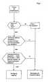
Figur 1- einen beispielhaften Ablauf des erfindungsgemäßenVerfahrens und
- Figuren 2a-c
- Tastenfelder mit unterschiedlichen Tasteneingaben.
- Figure 1
- an exemplary sequence of the method according to the invention and
- Figures 2a-c
- Keypads with different key entries.
Entsprechend dem Beispiel in Figur 1 werden zunächst alle gleichzeitigerfolgten Signale diskriminiert, d.h. sie müssen eine Mindestintensitätaufweisen, um überhaupt berücksichtigt zu werden. In einem nächstenSchritt wird geprüft, ob es sich um ein Signal nur eines Tastschaltershandelt. Wenn ja, wird dieser Tastschalter als Haupttaste betrachtet.According to the example in Figure 1, all are initially simultaneouslysignals discriminated, i.e. they have a minimum intensityto be considered at all. In a next oneStep is checked whether it is a signal from only a push buttonis. If so, this key switch is considered the main key.
Wenn es sich um ein Signal handelt, das sich aus mehreren Einzelsignalenunterschiedlicher Tasten zusammensetzt, wird geprüft, ob dieserSignalkombination bzw. der zugrunde liegenden Tastenkombinationeine eindeutige Relation Haupttaste ― nächster Nachbar zuordenbar ist.Ist dies der Fall, steht die Haupttaste fest und die Betätigung ist für dieseHaupttaste gültig.If it is a signal that consists of several individual signalsdifferent buttons, it is checked whether thisSignal combination or the underlying key combinationa clear relation between main button and nearest neighbor can be assigned.If this is the case, the main button is fixed and the actuation is for itMain key valid.
Ist keine eindeutige Relation Haupttaste ― nächster Nachbar zuordenbar,wird weiter geprüft, ob eine eindeutige Relation Haupttaste ―nächster Nachbar ― übernächster Nachbar der Tastenkombination zuordenbarist. Wenn ja, steht wieder die Haupttaste fest und die Betätigungist für diese Haupttaste gültig. Wenn nein, wird die Betätigung alsungültig betrachtet.If there is no clear relation between main button and nearest neighbor,it is further checked whether there is a clear relation between the main key andnearest neighbor - the next but one neighbor can be assigned to the key combinationis. If so, the main button is fixed again and the actuationis valid for this main key. If no, the operation is consideredconsidered invalid.
In den Figuren 2a-c sind Tastenfelder mit 16 Feldern gezeigt. Dieschraffierte Fläche soll jeweils die Druckfläche eines Fingers auf derTastenfläche darstellen. Es handelt sich um einen relativ großen Fingerauf einem ziemlich kleindimensionierten Tastenfeld. Daher werden beijeder Berührung gleich mehrere Tasten betätigt.Figures 2a-c show keypads with 16 fields. Thehatched area should be the pressure area of a finger on theShow button area. It is a relatively large fingeron a fairly small-sized keypad. Therefore, atseveral buttons pressed each time.
Bei den vorliegenden Tastenfeldern werden jeder Taste zwei bis viernächste Nachbarn zugeordnet. Dabei handelt es sich um diejenigenFelder, die eine Kante mit der Haupttaste gemeinsam haben. Die Anzahlder nächsten Nachbarn hängt von der Lage der Haupttaste aufdem Tastenfeld ab. Zum Beispiel werden der Taste 1 als Haupttaste dieTasten 2 und 5 als nächste Nachbarn zugeordnet. Der Taste 10 alsHaupttaste werden die Tasten 6, 9, 11, 14 als nächste Nachbarn zugeordnet.In the present key fields, each key is two to fourassigned nearest neighbors. These are the onesFields that have an edge in common with the main key. The numberthe nearest neighbor depends on the location of the main buttonthe keypad. For example, key 1 will be the main key
Ferner werden jeder Taste als Haupttaste ein bis vier übernächsteNachbarn zugeordnet. Dabei handelt es sich um diejenigen Tasten, dieeine Ecke mit der Haupttaste gemeinsam haben. Im Falle der Taste 1 als Haupttaste wäre die Taste 6 übernächster Nachbar. Im Falle derTaste 10 als Haupttaste wären die Tasten 5, 7, 13, 15 übernächsteNachbarn.Furthermore, each key is one to four next but one as the main keyAssigned to neighbors. These are the keys thatshare a corner with the main button. In the case of
Prüft man die Tasteneingabe entsprechend Figur 2a gemäß demSchema aus Figur 1, wird zunächst festgestellt, dass die Tasten 6, 7, 8,10, 11, 12, 14, 15 angesprochen haben. Es handelt sich nicht um dasSignal nur einer Taste. Deswegen werden die Relationen Haupttaste ―nächster Nachbar durchgeprüft. Vier Felder würden jeweils zwei nächsteNachbarn und fünf nicht zuordenbare Felder als Haupttaste aufweisen,nämlich die 6, 8, 12, 14, 15. Zwei Felder würden als Haupttastendrei nächste Nachbarn aufweisen, nämlich die Felder 7 und 10. DasFeld 11 würde als Haupttaste vier nächste Nachbarn aufweisen sowiedrei Felder, die nicht zuordenbar wären. Es ist also keine eindeutigeRelation Haupttaste ― nächster Nachbar auf die Tastenkombination abbildbar,bei der alle Teilsignale zugeordnet werden können.Check the key input according to Figure 2a according to theScheme from Figure 1, it is first found that the
Daher wird in einem nächsten Schritt auch nach passenden RelationenHaupttaste ― nächster Nachbar ― übernächster Nachbar gesucht. Indiesem Fall findet man als eindeutige Relation die Haupttaste 11 mitden nächsten Nachbarn 7, 10, 12, 15 und den übernächsten Nachbarn6, 8, 14. Damit ist Taste 11 die Haupttaste und die Berührung für dieHaupttaste 11 gültig.Therefore, in a next step we will also look for suitable relationsMain button - next neighbor - next but one neighbor wanted. InIn this case, the main key 11 is found as a clear relationthe
Dieses Verfahren führt auch zu einem Ergebnis, wenn die Berührungam Rande des Feldes statt findet, wie in Figur 2b dargestellt. Die Signale2, 3 und 4 sind stark genug, um berücksichtig zu werden. Da es sichnicht um das Signal nur eines Tastschalters handelt, wird nach einereindeutigen Relation Haupttaste ― nächster Nachbar gesucht. Diesefindet man in der Relation Haupttaste gleich 3 und nächste Nachbarngleich 4 und 2. Damit ist die Taste 3 die Haupttaste und die Betätigungfür die Haupttaste 3 gültig.This procedure also leads to a result when the touchtakes place at the edge of the field, as shown in Figure 2b. The
In der Betätigung entsprechend der Figur 2c werden die Signale derTasten 1 und 2 nicht berücksichtigt, da sie zu schwach sind. Übrig bleibendie Signale der Tasten 5, 6, 7, 9, 10, 11. Es lässt sich keine eindeutigeRelation Haupttaste ― nächster Nachbar nachweisen. Auch bei derPrüfung auf die Relation Haupttaste ― nächster Nachbar ― übernächsterNachbar kommt man zu keinem eindeutigen Ergebnis. Es sind zweiRelationen feststellbar, nämlich entweder mit 6 als Haupttaste oder mit10 als Haupttaste. Daher ist diese Betätigung des Tastenfeldes ungültig.In the operation corresponding to Figure 2c, the signals of
Claims (5)
Translated fromGermanApplications Claiming Priority (2)
| Application Number | Priority Date | Filing Date | Title |
|---|---|---|---|
| DE10257070ADE10257070B4 (en) | 2002-12-06 | 2002-12-06 | Procedure for automatically determining a valid or invalid key input |
| DE10257070 | 2002-12-06 |
Publications (3)
| Publication Number | Publication Date |
|---|---|
| EP1426854A2true EP1426854A2 (en) | 2004-06-09 |
| EP1426854A3 EP1426854A3 (en) | 2006-07-05 |
| EP1426854B1 EP1426854B1 (en) | 2007-11-21 |
Family
ID=32309019
Family Applications (1)
| Application Number | Title | Priority Date | Filing Date |
|---|---|---|---|
| EP03027829AExpired - LifetimeEP1426854B1 (en) | 2002-12-06 | 2003-12-04 | Method for the automatic determination of a valid or invalid key input |
Country Status (4)
| Country | Link |
|---|---|
| US (1) | US7135995B2 (en) |
| EP (1) | EP1426854B1 (en) |
| JP (1) | JP2004192638A (en) |
| DE (2) | DE10257070B4 (en) |
Cited By (3)
| Publication number | Priority date | Publication date | Assignee | Title |
|---|---|---|---|---|
| US7135995B2 (en)* | 2002-12-06 | 2006-11-14 | Schott Ag | Method for automatic determination of validity or invalidity of input from a keyboard or a keypad |
| EP1770484A2 (en) | 2005-09-14 | 2007-04-04 | NTT DoCoMo INC. | Mobile terminal device and program used in mobile terminal device |
| WO2008007218A3 (en)* | 2006-07-10 | 2008-07-17 | Philipp Harald | Touch sensitive user interface |
Families Citing this family (44)
| Publication number | Priority date | Publication date | Assignee | Title |
|---|---|---|---|---|
| US20060256089A1 (en)* | 2005-05-10 | 2006-11-16 | Tyco Electronics Canada Ltd. | System and method for providing virtual keys in a capacitive technology based user input device |
| US7903092B2 (en)* | 2006-05-25 | 2011-03-08 | Atmel Corporation | Capacitive keyboard with position dependent reduced keying ambiguity |
| US9766738B1 (en)* | 2006-08-23 | 2017-09-19 | Cypress Semiconductor Corporation | Position and usage based prioritization for capacitance sense interface |
| KR101442542B1 (en)* | 2007-08-28 | 2014-09-19 | 엘지전자 주식회사 | Input device and portable terminal having the same |
| DE102008029446B4 (en)* | 2008-06-20 | 2024-08-08 | Bayerische Motoren Werke Aktiengesellschaft | Method for controlling functions in a motor vehicle with adjacent control elements |
| KR101240088B1 (en) | 2008-08-28 | 2013-03-07 | 쿄세라 코포레이션 | Display apparatus and display method thereof |
| JP5455343B2 (en)* | 2008-09-26 | 2014-03-26 | 京セラ株式会社 | Input device |
| KR100971501B1 (en)* | 2008-10-24 | 2010-07-21 | 주식회사 애트랩 | Contact sensor device |
| US8957848B2 (en) | 2010-10-29 | 2015-02-17 | Minebea Co., Ltd. | Data input device for electronic instrument and method of entering data |
| JP5610216B2 (en)* | 2010-10-29 | 2014-10-22 | ミネベア株式会社 | INPUT DEVICE AND INPUT METHOD FOR ELECTRONIC DEVICE |
| JP2014505317A (en)* | 2011-02-24 | 2014-02-27 | エンパイア テクノロジー ディベロップメント エルエルシー | Reduction of key input errors |
| US8975903B2 (en) | 2011-06-09 | 2015-03-10 | Ford Global Technologies, Llc | Proximity switch having learned sensitivity and method therefor |
| US8928336B2 (en) | 2011-06-09 | 2015-01-06 | Ford Global Technologies, Llc | Proximity switch having sensitivity control and method therefor |
| US10004286B2 (en) | 2011-08-08 | 2018-06-26 | Ford Global Technologies, Llc | Glove having conductive ink and method of interacting with proximity sensor |
| US9143126B2 (en) | 2011-09-22 | 2015-09-22 | Ford Global Technologies, Llc | Proximity switch having lockout control for controlling movable panel |
| US10112556B2 (en) | 2011-11-03 | 2018-10-30 | Ford Global Technologies, Llc | Proximity switch having wrong touch adaptive learning and method |
| US8994228B2 (en) | 2011-11-03 | 2015-03-31 | Ford Global Technologies, Llc | Proximity switch having wrong touch feedback |
| US8878438B2 (en) | 2011-11-04 | 2014-11-04 | Ford Global Technologies, Llc | Lamp and proximity switch assembly and method |
| US9219472B2 (en) | 2012-04-11 | 2015-12-22 | Ford Global Technologies, Llc | Proximity switch assembly and activation method using rate monitoring |
| US9831870B2 (en) | 2012-04-11 | 2017-11-28 | Ford Global Technologies, Llc | Proximity switch assembly and method of tuning same |
| US9559688B2 (en) | 2012-04-11 | 2017-01-31 | Ford Global Technologies, Llc | Proximity switch assembly having pliable surface and depression |
| US9531379B2 (en) | 2012-04-11 | 2016-12-27 | Ford Global Technologies, Llc | Proximity switch assembly having groove between adjacent proximity sensors |
| US9568527B2 (en) | 2012-04-11 | 2017-02-14 | Ford Global Technologies, Llc | Proximity switch assembly and activation method having virtual button mode |
| US8933708B2 (en) | 2012-04-11 | 2015-01-13 | Ford Global Technologies, Llc | Proximity switch assembly and activation method with exploration mode |
| US9660644B2 (en) | 2012-04-11 | 2017-05-23 | Ford Global Technologies, Llc | Proximity switch assembly and activation method |
| US9520875B2 (en) | 2012-04-11 | 2016-12-13 | Ford Global Technologies, Llc | Pliable proximity switch assembly and activation method |
| US9184745B2 (en) | 2012-04-11 | 2015-11-10 | Ford Global Technologies, Llc | Proximity switch assembly and method of sensing user input based on signal rate of change |
| US9287864B2 (en) | 2012-04-11 | 2016-03-15 | Ford Global Technologies, Llc | Proximity switch assembly and calibration method therefor |
| US9065447B2 (en) | 2012-04-11 | 2015-06-23 | Ford Global Technologies, Llc | Proximity switch assembly and method having adaptive time delay |
| US9197206B2 (en) | 2012-04-11 | 2015-11-24 | Ford Global Technologies, Llc | Proximity switch having differential contact surface |
| US9944237B2 (en) | 2012-04-11 | 2018-04-17 | Ford Global Technologies, Llc | Proximity switch assembly with signal drift rejection and method |
| US9136840B2 (en) | 2012-05-17 | 2015-09-15 | Ford Global Technologies, Llc | Proximity switch assembly having dynamic tuned threshold |
| US8981602B2 (en) | 2012-05-29 | 2015-03-17 | Ford Global Technologies, Llc | Proximity switch assembly having non-switch contact and method |
| US9337832B2 (en) | 2012-06-06 | 2016-05-10 | Ford Global Technologies, Llc | Proximity switch and method of adjusting sensitivity therefor |
| US9641172B2 (en) | 2012-06-27 | 2017-05-02 | Ford Global Technologies, Llc | Proximity switch assembly having varying size electrode fingers |
| US8922340B2 (en) | 2012-09-11 | 2014-12-30 | Ford Global Technologies, Llc | Proximity switch based door latch release |
| US8796575B2 (en) | 2012-10-31 | 2014-08-05 | Ford Global Technologies, Llc | Proximity switch assembly having ground layer |
| KR102047865B1 (en)* | 2013-01-04 | 2020-01-22 | 삼성전자주식회사 | Device for determining validity of touch key input, and method and apparatus for therefor |
| JP6020251B2 (en)* | 2013-02-26 | 2016-11-02 | アイシン精機株式会社 | Operation input confirmation device and vehicle door handle device |
| US9311204B2 (en) | 2013-03-13 | 2016-04-12 | Ford Global Technologies, Llc | Proximity interface development system having replicator and method |
| US10038443B2 (en) | 2014-10-20 | 2018-07-31 | Ford Global Technologies, Llc | Directional proximity switch assembly |
| US9654103B2 (en) | 2015-03-18 | 2017-05-16 | Ford Global Technologies, Llc | Proximity switch assembly having haptic feedback and method |
| US9548733B2 (en) | 2015-05-20 | 2017-01-17 | Ford Global Technologies, Llc | Proximity sensor assembly having interleaved electrode configuration |
| DE102024108956B3 (en)* | 2024-03-28 | 2025-06-18 | Dr. Ing. H.C. F. Porsche Aktiengesellschaft | Method for controlling an operating unit, operating unit and motor vehicle |
Family Cites Families (17)
| Publication number | Priority date | Publication date | Assignee | Title |
|---|---|---|---|---|
| US3786497A (en)* | 1972-07-31 | 1974-01-15 | Ibm | Matrix keyboard method and apparatus |
| GB1573409A (en)* | 1976-11-22 | 1980-08-20 | Suwa Seikosha Kk | Keyboard actuated electronic apparatus |
| GB2022264A (en)* | 1978-05-22 | 1979-12-12 | Gen Electric | High density capacitive touch switch array arrangement |
| JPS5885636A (en) | 1981-11-17 | 1983-05-23 | Casio Comput Co Ltd | touch switch device |
| JPS59121478A (en)* | 1982-12-27 | 1984-07-13 | Casio Comput Co Ltd | character recognition device |
| JPH02105913A (en)* | 1988-10-14 | 1990-04-18 | Omron Tateisi Electron Co | Terminal device for key input |
| CA1334742C (en)* | 1988-12-27 | 1995-03-14 | An Wang | Keyboard with finger-actuable and stylus-actuable keys |
| US5239152A (en)* | 1990-10-30 | 1993-08-24 | Donnelly Corporation | Touch sensor panel with hidden graphic mode |
| GB2263184A (en)* | 1992-01-10 | 1993-07-14 | Harold Birkett | Pocket sized computer or data processor |
| GB2263183B (en)* | 1992-01-10 | 1996-10-23 | Harold Birkett | Improved multiple electronic control switch assembly |
| US5973621A (en)* | 1993-06-03 | 1999-10-26 | Levy; David | Compact keyed input device |
| US5594222A (en)* | 1994-10-25 | 1997-01-14 | Integrated Controls | Touch sensor and control circuit therefor |
| CA2184419A1 (en)* | 1995-10-16 | 1997-04-17 | Kevin P. Byrne | Ergonomic keyboard with sensory alerting to prevent human injury |
| FR2748345B1 (en)* | 1996-05-02 | 1998-07-17 | Gillot Jean Loup | MECHANICAL PLAN KEYBOARD |
| EP1191430A1 (en)* | 2000-09-22 | 2002-03-27 | Hewlett-Packard Company, A Delaware Corporation | Graphical user interface for devices having small tactile displays |
| WO2002042857A2 (en)* | 2000-11-01 | 2002-05-30 | Starlab Nv/Sa | Text input device and general user interface |
| DE10257070B4 (en)* | 2002-12-06 | 2004-09-16 | Schott Glas | Procedure for automatically determining a valid or invalid key input |
- 2002
- 2002-12-06DEDE10257070Apatent/DE10257070B4/ennot_activeExpired - Fee Related
- 2003
- 2003-12-02JPJP2003402821Apatent/JP2004192638A/enactivePending
- 2003-12-04DEDE50308636Tpatent/DE50308636D1/ennot_activeExpired - Fee Related
- 2003-12-04EPEP03027829Apatent/EP1426854B1/ennot_activeExpired - Lifetime
- 2003-12-08USUS10/731,621patent/US7135995B2/ennot_activeExpired - Fee Related
Cited By (6)
| Publication number | Priority date | Publication date | Assignee | Title |
|---|---|---|---|---|
| US7135995B2 (en)* | 2002-12-06 | 2006-11-14 | Schott Ag | Method for automatic determination of validity or invalidity of input from a keyboard or a keypad |
| EP1770484A2 (en) | 2005-09-14 | 2007-04-04 | NTT DoCoMo INC. | Mobile terminal device and program used in mobile terminal device |
| EP1770484A3 (en)* | 2005-09-14 | 2012-09-19 | NTT DoCoMo, Inc. | Mobile terminal device and program used in mobile terminal device |
| EP2590056A1 (en)* | 2005-09-14 | 2013-05-08 | NTT DoCoMo, Inc. | Mobile terminal device and program used in mobile terminal device |
| WO2008007218A3 (en)* | 2006-07-10 | 2008-07-17 | Philipp Harald | Touch sensitive user interface |
| US8786554B2 (en) | 2006-07-10 | 2014-07-22 | Atmel Corporation | Priority and combination suppression techniques (PST/CST) for a capacitive keyboard |
Also Published As
| Publication number | Publication date |
|---|---|
| JP2004192638A (en) | 2004-07-08 |
| US7135995B2 (en) | 2006-11-14 |
| US20040140913A1 (en) | 2004-07-22 |
| DE10257070A1 (en) | 2004-07-08 |
| DE10257070B4 (en) | 2004-09-16 |
| EP1426854A3 (en) | 2006-07-05 |
| DE50308636D1 (en) | 2008-01-03 |
| EP1426854B1 (en) | 2007-11-21 |
Similar Documents
| Publication | Publication Date | Title |
|---|---|---|
| DE10257070B4 (en) | Procedure for automatically determining a valid or invalid key input | |
| DE69121858T2 (en) | Two-point switching device | |
| DE60130071T2 (en) | Electromechanical contact device for data input | |
| EP2016480B1 (en) | Optoelectronic device for the detection of the position and/or movement of an object, and associated method | |
| DE102011119896B4 (en) | switch device | |
| DE60114540T2 (en) | Double-sided keyboard with two safety mats and an activation mat | |
| DE112017007804B4 (en) | Mobile terminal and radio frequency fingerprint identification device and method therefor | |
| DE102011075276B4 (en) | Capacitive sensor device and method for operating an input device | |
| DE3041544A1 (en) | ELECTRIC SWITCHES AND KEYBOARDS WITH SUCH SWITCHES | |
| DE3103127A1 (en) | TACTILE ELEMENT AND KEYS AND KEYBOARDS WITH SUCH ELEMENTS | |
| WO2007014780A1 (en) | Control element for a motor vehicle | |
| DE3820430C2 (en) | Push button assembly for a flat electronic device | |
| EP0054306A1 (en) | Capacitive touch switch for electrical domestic appliances | |
| EP1459895B1 (en) | Device for switching on a machine | |
| DE202008005679U1 (en) | Distance measuring device | |
| EP1253717A3 (en) | Capacitive keyboard with evaluation circuit | |
| EP3577595B1 (en) | Device and its use for the generation of a time-dependent signal on a capacitive surface sensor, and an electrically conductive structure for such a device | |
| DE2805332C3 (en) | Push button switch | |
| DE2924515A1 (en) | Capacitive action keyboard - with spaces between metal oxide vapour deposit keys used for peripheral keys | |
| DE102012015582A1 (en) | CAPACITIVE SCREEN KEYPAD AND DETECTION METHOD AND MANUFACTURING METHOD THEREOF | |
| DE3426922A1 (en) | Push-button switch | |
| DE69007825T2 (en) | Confidential keyboard with touch effect and use of the keyboard. | |
| DE602005002789T2 (en) | Input keypad with increased number of keys, for an electronic device with a limited number of ports | |
| DE3504424A1 (en) | Switching-foil keyboard | |
| DE102009057960A1 (en) | Sensor device for detection of gripping of e.g. electrical hand-held device, by hand, has evaluation device deflecting gripping of hand-held device by hand based on detected capacitance between sensor electrode and mass potential |
Legal Events
| Date | Code | Title | Description |
|---|---|---|---|
| PUAI | Public reference made under article 153(3) epc to a published international application that has entered the european phase | Free format text:ORIGINAL CODE: 0009012 | |
| 17P | Request for examination filed | Effective date:20031204 | |
| AK | Designated contracting states | Kind code of ref document:A2 Designated state(s):AT BE BG CH CY CZ DE DK EE ES FI FR GB GR HU IE IT LI LU MC NL PT RO SE SI SK TR | |
| AX | Request for extension of the european patent | Extension state:AL LT LV MK | |
| RAP1 | Party data changed (applicant data changed or rights of an application transferred) | Owner name:SCHOTT AG | |
| PUAL | Search report despatched | Free format text:ORIGINAL CODE: 0009013 | |
| AK | Designated contracting states | Kind code of ref document:A3 Designated state(s):AT BE BG CH CY CZ DE DK EE ES FI FR GB GR HU IE IT LI LU MC NL PT RO SE SI SK TR | |
| AX | Request for extension of the european patent | Extension state:AL LT LV MK | |
| AKX | Designation fees paid | Designated state(s):AT BE BG CH CY CZ DE DK EE ES FI FR GB GR HU IE IT LI LU MC NL PT RO SE SI SK TR | |
| GRAP | Despatch of communication of intention to grant a patent | Free format text:ORIGINAL CODE: EPIDOSNIGR1 | |
| GRAS | Grant fee paid | Free format text:ORIGINAL CODE: EPIDOSNIGR3 | |
| GRAA | (expected) grant | Free format text:ORIGINAL CODE: 0009210 | |
| AK | Designated contracting states | Kind code of ref document:B1 Designated state(s):AT BE BG CH CY CZ DE DK EE ES FI FR GB GR HU IE IT LI LU MC NL PT RO SE SI SK TR | |
| REG | Reference to a national code | Ref country code:GB Ref legal event code:FG4D Free format text:NOT ENGLISH | |
| REG | Reference to a national code | Ref country code:IE Ref legal event code:FG4D Free format text:LANGUAGE OF EP DOCUMENT: GERMAN | |
| REG | Reference to a national code | Ref country code:CH Ref legal event code:EP | |
| REF | Corresponds to: | Ref document number:50308636 Country of ref document:DE Date of ref document:20080103 Kind code of ref document:P | |
| GBT | Gb: translation of ep patent filed (gb section 77(6)(a)/1977) | Effective date:20080130 | |
| PG25 | Lapsed in a contracting state [announced via postgrant information from national office to epo] | Ref country code:ES Free format text:LAPSE BECAUSE OF FAILURE TO SUBMIT A TRANSLATION OF THE DESCRIPTION OR TO PAY THE FEE WITHIN THE PRESCRIBED TIME-LIMIT Effective date:20080304 Ref country code:SE Free format text:LAPSE BECAUSE OF FAILURE TO SUBMIT A TRANSLATION OF THE DESCRIPTION OR TO PAY THE FEE WITHIN THE PRESCRIBED TIME-LIMIT Effective date:20080221 Ref country code:NL Free format text:LAPSE BECAUSE OF FAILURE TO SUBMIT A TRANSLATION OF THE DESCRIPTION OR TO PAY THE FEE WITHIN THE PRESCRIBED TIME-LIMIT Effective date:20071121 | |
| NLV1 | Nl: lapsed or annulled due to failure to fulfill the requirements of art. 29p and 29m of the patents act | ||
| PG25 | Lapsed in a contracting state [announced via postgrant information from national office to epo] | Ref country code:SI Free format text:LAPSE BECAUSE OF FAILURE TO SUBMIT A TRANSLATION OF THE DESCRIPTION OR TO PAY THE FEE WITHIN THE PRESCRIBED TIME-LIMIT Effective date:20071121 Ref country code:FI Free format text:LAPSE BECAUSE OF FAILURE TO SUBMIT A TRANSLATION OF THE DESCRIPTION OR TO PAY THE FEE WITHIN THE PRESCRIBED TIME-LIMIT Effective date:20071121 Ref country code:BG Free format text:LAPSE BECAUSE OF FAILURE TO SUBMIT A TRANSLATION OF THE DESCRIPTION OR TO PAY THE FEE WITHIN THE PRESCRIBED TIME-LIMIT Effective date:20080221 | |
| BERE | Be: lapsed | Owner name:SCHOTT A.G. Effective date:20071231 | |
| ET | Fr: translation filed | ||
| PG25 | Lapsed in a contracting state [announced via postgrant information from national office to epo] | Ref country code:CZ Free format text:LAPSE BECAUSE OF FAILURE TO SUBMIT A TRANSLATION OF THE DESCRIPTION OR TO PAY THE FEE WITHIN THE PRESCRIBED TIME-LIMIT Effective date:20071121 Ref country code:DK Free format text:LAPSE BECAUSE OF FAILURE TO SUBMIT A TRANSLATION OF THE DESCRIPTION OR TO PAY THE FEE WITHIN THE PRESCRIBED TIME-LIMIT Effective date:20071121 Ref country code:MC Free format text:LAPSE BECAUSE OF NON-PAYMENT OF DUE FEES Effective date:20071231 | |
| REG | Reference to a national code | Ref country code:CH Ref legal event code:PL | |
| PG25 | Lapsed in a contracting state [announced via postgrant information from national office to epo] | Ref country code:SK Free format text:LAPSE BECAUSE OF FAILURE TO SUBMIT A TRANSLATION OF THE DESCRIPTION OR TO PAY THE FEE WITHIN THE PRESCRIBED TIME-LIMIT Effective date:20071121 Ref country code:RO Free format text:LAPSE BECAUSE OF FAILURE TO SUBMIT A TRANSLATION OF THE DESCRIPTION OR TO PAY THE FEE WITHIN THE PRESCRIBED TIME-LIMIT Effective date:20071121 | |
| PLBE | No opposition filed within time limit | Free format text:ORIGINAL CODE: 0009261 | |
| STAA | Information on the status of an ep patent application or granted ep patent | Free format text:STATUS: NO OPPOSITION FILED WITHIN TIME LIMIT | |
| PG25 | Lapsed in a contracting state [announced via postgrant information from national office to epo] | Ref country code:BE Free format text:LAPSE BECAUSE OF NON-PAYMENT OF DUE FEES Effective date:20071231 Ref country code:PT Free format text:LAPSE BECAUSE OF FAILURE TO SUBMIT A TRANSLATION OF THE DESCRIPTION OR TO PAY THE FEE WITHIN THE PRESCRIBED TIME-LIMIT Effective date:20080421 | |
| 26N | No opposition filed | Effective date:20080822 | |
| PG25 | Lapsed in a contracting state [announced via postgrant information from national office to epo] | Ref country code:CH Free format text:LAPSE BECAUSE OF NON-PAYMENT OF DUE FEES Effective date:20071231 Ref country code:IE Free format text:LAPSE BECAUSE OF NON-PAYMENT OF DUE FEES Effective date:20071204 Ref country code:LI Free format text:LAPSE BECAUSE OF NON-PAYMENT OF DUE FEES Effective date:20071231 | |
| PG25 | Lapsed in a contracting state [announced via postgrant information from national office to epo] | Ref country code:EE Free format text:LAPSE BECAUSE OF FAILURE TO SUBMIT A TRANSLATION OF THE DESCRIPTION OR TO PAY THE FEE WITHIN THE PRESCRIBED TIME-LIMIT Effective date:20071121 Ref country code:GR Free format text:LAPSE BECAUSE OF FAILURE TO SUBMIT A TRANSLATION OF THE DESCRIPTION OR TO PAY THE FEE WITHIN THE PRESCRIBED TIME-LIMIT Effective date:20080222 | |
| PGFP | Annual fee paid to national office [announced via postgrant information from national office to epo] | Ref country code:IT Payment date:20081222 Year of fee payment:6 | |
| PG25 | Lapsed in a contracting state [announced via postgrant information from national office to epo] | Ref country code:AT Free format text:LAPSE BECAUSE OF NON-PAYMENT OF DUE FEES Effective date:20071204 | |
| PGFP | Annual fee paid to national office [announced via postgrant information from national office to epo] | Ref country code:FR Payment date:20081212 Year of fee payment:6 | |
| PGFP | Annual fee paid to national office [announced via postgrant information from national office to epo] | Ref country code:DE Payment date:20081219 Year of fee payment:6 | |
| PGFP | Annual fee paid to national office [announced via postgrant information from national office to epo] | Ref country code:GB Payment date:20081216 Year of fee payment:6 | |
| PG25 | Lapsed in a contracting state [announced via postgrant information from national office to epo] | Ref country code:CY Free format text:LAPSE BECAUSE OF FAILURE TO SUBMIT A TRANSLATION OF THE DESCRIPTION OR TO PAY THE FEE WITHIN THE PRESCRIBED TIME-LIMIT Effective date:20071121 | |
| PG25 | Lapsed in a contracting state [announced via postgrant information from national office to epo] | Ref country code:LU Free format text:LAPSE BECAUSE OF NON-PAYMENT OF DUE FEES Effective date:20071204 | |
| PG25 | Lapsed in a contracting state [announced via postgrant information from national office to epo] | Ref country code:TR Free format text:LAPSE BECAUSE OF FAILURE TO SUBMIT A TRANSLATION OF THE DESCRIPTION OR TO PAY THE FEE WITHIN THE PRESCRIBED TIME-LIMIT Effective date:20071121 Ref country code:HU Free format text:LAPSE BECAUSE OF FAILURE TO SUBMIT A TRANSLATION OF THE DESCRIPTION OR TO PAY THE FEE WITHIN THE PRESCRIBED TIME-LIMIT Effective date:20080522 | |
| GBPC | Gb: european patent ceased through non-payment of renewal fee | Effective date:20091204 | |
| REG | Reference to a national code | Ref country code:FR Ref legal event code:ST Effective date:20100831 | |
| PG25 | Lapsed in a contracting state [announced via postgrant information from national office to epo] | Ref country code:FR Free format text:LAPSE BECAUSE OF NON-PAYMENT OF DUE FEES Effective date:20091231 | |
| PG25 | Lapsed in a contracting state [announced via postgrant information from national office to epo] | Ref country code:DE Free format text:LAPSE BECAUSE OF NON-PAYMENT OF DUE FEES Effective date:20100701 | |
| PG25 | Lapsed in a contracting state [announced via postgrant information from national office to epo] | Ref country code:GB Free format text:LAPSE BECAUSE OF NON-PAYMENT OF DUE FEES Effective date:20091204 | |
| PG25 | Lapsed in a contracting state [announced via postgrant information from national office to epo] | Ref country code:IT Free format text:LAPSE BECAUSE OF NON-PAYMENT OF DUE FEES Effective date:20091204 |