EP1418776B1 - Frequency reuse method in an orthogonal frequency division multiplex mobile communication system (OFDM) - Google Patents
Frequency reuse method in an orthogonal frequency division multiplex mobile communication system (OFDM)Download PDFInfo
- Publication number
- EP1418776B1 EP1418776B1EP20030078518EP03078518AEP1418776B1EP 1418776 B1EP1418776 B1EP 1418776B1EP 20030078518EP20030078518EP 20030078518EP 03078518 AEP03078518 AEP 03078518AEP 1418776 B1EP1418776 B1EP 1418776B1
- Authority
- EP
- European Patent Office
- Prior art keywords
- frequency
- ofdm
- sub
- groups
- channel
- Prior art date
- Legal status (The legal status is an assumption and is not a legal conclusion. Google has not performed a legal analysis and makes no representation as to the accuracy of the status listed.)
- Expired - Lifetime
Links
Images


Classifications
- H—ELECTRICITY
- H04—ELECTRIC COMMUNICATION TECHNIQUE
- H04W—WIRELESS COMMUNICATION NETWORKS
- H04W16/00—Network planning, e.g. coverage or traffic planning tools; Network deployment, e.g. resource partitioning or cells structures
- H04W16/02—Resource partitioning among network components, e.g. reuse partitioning
- H04W16/12—Fixed resource partitioning
- H—ELECTRICITY
- H04—ELECTRIC COMMUNICATION TECHNIQUE
- H04L—TRANSMISSION OF DIGITAL INFORMATION, e.g. TELEGRAPHIC COMMUNICATION
- H04L5/00—Arrangements affording multiple use of the transmission path
- H04L5/02—Channels characterised by the type of signal
- H04L5/023—Multiplexing of multicarrier modulation signals, e.g. multi-user orthogonal frequency division multiple access [OFDMA]
- H—ELECTRICITY
- H04—ELECTRIC COMMUNICATION TECHNIQUE
- H04W—WIRELESS COMMUNICATION NETWORKS
- H04W16/00—Network planning, e.g. coverage or traffic planning tools; Network deployment, e.g. resource partitioning or cells structures
- H04W16/02—Resource partitioning among network components, e.g. reuse partitioning
- H—ELECTRICITY
- H04—ELECTRIC COMMUNICATION TECHNIQUE
- H04W—WIRELESS COMMUNICATION NETWORKS
- H04W28/00—Network traffic management; Network resource management
- H04W28/16—Central resource management; Negotiation of resources or communication parameters, e.g. negotiating bandwidth or QoS [Quality of Service]
- H04W28/26—Resource reservation
Definitions
- the present inventionrelates generally to a frequency reuse method in a mobile communication system, and in particular, to a frequency reuse method in an orthogonal frequency division multiplex (OFDM) mobile communication system.
- OFDMorthogonal frequency division multiplex
- Mobile communication systemsare designed to provide voice service, ensuring mobility for users. Owing to the drastic development of mobile communication technology and ever-increasing user demands, these mobile communication systems have been developed to additionally provide data service. Data transmission has been evolved from short messages to Internet service. Today, high-rate data transmission such as moving pictures is possible. Transmission schemes, developed from traditional cellular systems, are now under discussion for standardization in the 3 rd generation partnership project (3GPP).
- the 3G mobile communication systemsare categorized into synchronous code division multiple access (CDMA) and asynchronous CDMA.
- OFDMis a type of multi-carrier modulation.
- OFDM spread spectrum technologydistributes data over multiple carriers spaced from each other with respect to a central frequency, thereby offering orthogonality between the carriers.
- the OFDMhas excellent performance in a multi-path radio environment. For this reason, the OFDM attracts much interest as a suitable modulation scheme for digital terrestrial television service and digital audio broadcasting. Hence it is expected that the OFDM will be adopted as a digital television standard in Europe, Japan, and Australia and is currently envisioned for use in a fourth generation mobile communications system.
- the OFDMhas the following advantages.
- one base stationcan not use all of the available OFDM frequency channels in view of the orthogonality of frequencies used. If a total of 512 frequency channels are available and 4 or 32 frequency channels, here 4 frequency channels are assigned to one user, up to 128 resources are available to a BS. In the case where each BS is allowed to use the 128 resources, the same frequency resources may be used in different BSs. Supposing that there are BS A and BS B adjacent to BS A, both BSs may assign the same 4 channels to mobile stations (MSs) within their cells. If the MSs are near to each other, they experience deterioration of carrier-to-interference ratio (C/I) characteristics.
- C/Icarrier-to-interference ratio
- each BSadaptively assigns carriers according to interference.
- the BSassigns a higher priority to an unused frequency in an adjacent BS. It further prioritizes frequencies used in adjacent BSs according to distances between MSs within its cell and those within the adjacent cells.
- the BSassigns higher-priority frequencies before lower-priority ones.
- the BSmust predetermine the frequencies that adjacent BSs are using and calculate the distances between an MS being serviced within its cell and MSs being serviced within the adjacent cells. As a result, system complexity is increased.
- Fig. 1illustrates a conventional frequency reuse scheme with a frequency reuse distance of 3 in an OFDM cellular mobile communication system.
- a complete frequency bandwidthis partitioned into three parts.
- a third of the bandwidthis available to each BS so that each of BSs 110 to 160 uses a different frequency from those of its adjacent BSs.
- BS 100uses a third of the carrier indexes and its adjacent BSs 120 to 160 use the other two thirds of carrier indexes. Similar system design occurs at the other BSs.
- the frequency reuse distanceis 3.
- cellular systemsimplement frequency reuse with a longer frequency distance based on this principle.
- the above conventional frequency reuse schemehas the distinctive shortcoming that the entire frequency bandwidth cannot be fully utilized in each cell.
- the number of channels available to a particular BSis the number of serviceable users or the data rates of services. Therefore, the decrease of the number of available channels limits the number of serviceable users or the data rates.
- EP 0 782 360 A1discloses a system and method for a cellular wireless communications system wherein each cell is divided in an inner cell and an outer cell. Reuse partitioning of frequency resources is employed to minimize neighbor-channel interference.
- WO 02/ 49306 A2discloses a method for subcarrier selection for a system employing orthogonal frequency division multiple access (OFDMA).
- Subcarriersare partitioned into a plurality of groups and each group comprises at least one cluster of subcarriers.
- a subscribermay indicate a selection of one or more groups.
- At least one clusteris then allocated for use in communication with the subscriber.
- US 5 953 661discloses a system and method for operating a cellular communication system.
- Cells of said cellular communication systemare divided into outer cells and inner cells.
- At least two frequency reuse patternsare assigned to the cells, one pattern to the outer cells and another, tighter pattern to the inner cells.
- an object of the present inventionto provide a method of increasing frequency reuse in an OFDM mobile communication system.
- Frequency resources available to each BSare divided into at least four frequency groups and a frequency reuse distance is set for each of the frequency groups.
- the frequency reuse distance set for each of the frequency groupcan be the same or different.
- the frequency groupsare sequentially assigned to cell areas of each BS such that lower frequency groups are available to a near cell area and higher frequency resource groups are available to a remote cell area.
- Each of the frequency groupsincludes successive carriers.
- the frequency resourcesare divided into the at least four frequency groups according to frequency hopping patterns.
- At least one of the frequency groupsis used with a frequency reuse distance of I in the near cell area.
- the near cell areais defined according to one of the distance from the BS, a system-required carrier-to-interference ratio (C/I), or interference from an adjacent BS.
- the at least four frequency groupsare of the same size.
- a BShaving first frequency resources for a near cell area and second frequency resources for a remote cell area, determines one of the distance between the BS and an MS, received signal strength, or interference from an adjacent BS, upon request of the MS for OFDM frequency setup. If a predetermined condition is satisfied, the BS establishes a channel with the MS by assigning a first OFDM frequency resource to the MS. If the MS is outside of the near cell area, the BS establishes a channel with the MS by assigning a second OFDM frequency resource to the MS.
- each BScommunicating with MSs in OFDM, having at least two sub-channel groups, and assigning OFDM frequency resources to an MS requesting a communication
- the BScompares the SIR of an MS with a predetermined reference SIR, upon request for an OFDM frequency setup from the MS, and assigns OFDM frequency resources in a low sub-channel group to the MS if the SIR of the MS is lower than the reference SIR.
- the BSassigns to the MS OFDM frequency resources in a sub-channel group corresponding to the lowest of reference SIRs higher than the SIR of the MS.
- the sub-channel group for the MSis determined according to the SIR and lognormal fading-including signal loss of the MS.
- an OFDM frequency reuse distancecan be 3, 4, 7, ....
- hexagonal-shaped cellsare artificial and such a shape cannot be generated in the real world, that is, each BS has a different shape of cell coverage, the ideal hexagonal cell shapes are assumed herein.
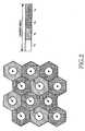
- Fig. 2illustrates a frequency reuse scheme in an OFDM mobile communication system according to an embodiment of the present invention.
- a given frequency bandwidthis partitioned into four carrier index groups n 1 to n 4 in order to obtain two frequency reuse distances of 3 and 1. If any other frequency reuse distances are adopted, the frequency bandwidth is partitioned into more or less parts.
- the reason for using the two frequency reuse distancesis to achieve a satisfactory C/I at cell borders or cell edges when the frequency reuse distance of 3 is used. As the system requires a higher C/I level, or propagation loss and fading variance are great, a greater frequency reuse distance, should be used.
- the frequency reuse distanceis varied according to the configuration of the BSs (i.e., propagation distance, propagation losses, fading variance, system-required C/I, and distance between BS and MS).
- a different frequency reuse distanceis used according to the distance from a BS.
- OFDM carriersare assigned with a frequency reuse distance of 1 in a near cell area and with a frequency reuse distance of 3 in a remote cell area.
- the cell areacan be divided according to C/I instead of the distance. In this case, the cell area is divided into a good channel-condition area and a bad channel-condition area. Since the C/I varies with the layout of buildings and the type of geographic terrain contour, the shapes of cell area coverages are different, which will be described later with reference to Fig. 5.
- the frequencies of carrier index group n 1are used in an area apart from each BS by a predetermined distance or less with a frequency reuse distance of 1.
- the areasare called “near areas (inner cells)" which are circular with respect to the BSs 200 to 260.
- the remaining areasare called “remote areas (outer cells).”
- MSs within the near areasgenerally have good C/I characteristics.
- the distinction between the near areas and the remote areascan be made by system-required C/I and interference from adjacent BSs, instead of distance.
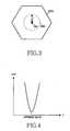
- Fig. 3illustrates a cell which is divided into a near area and a remote area according to distance from a BS in the present invention.
- the cell 200a of the BS 200covers its signal propagation distance.
- the cell coverageis divided into a near area 200b with a radius r that is changed according to the characteristics and geographical features of the BS 200.
- the remaining area outside of the near area 2006 of the cell coverageis defined as a remote area.
- application of the frequency reuse distance of 1 to the near area 200bdoes not affect MSs within other cells.
- OFDM frequenciesare reused in the remote areas as done in the conventional frequency reuse scheme.
- OFDM frequenciesare assigned to the remote areas of the BSs 200 to 260 without overlapped areas.
- the carrier index groups n 2 , n 3 and n 4are available to BSs 200 to 260.
- each BSassigns a channel to an MS in its remote area within resources assigned to the BS. For example, if the carrier index group n 2 is available to BS 200, BS 200 assigns a channel within the available frequency band to an MS in its remote area.
- BS 200assigns a channel within the carrier index group n 1 to the MS.
- the carrier index group n 3is available to BS 210, the BS 210 assigns a channel in the carrier index group n 1 to an MS in its near area and a channel in the carrier index group n 3 to an MS in its remote area, as illustrated in Fig. 2.
- Fig. 5illustrates a cell that is divided into a near area and a remote area according to signal strength or C/I in the present invention.
- the distance-based near area 200b and a C/I-based near area 200Chave different borders due to the channel condition between BS 200 and an MS, propagation loss, and the geographical features. While not shown, cell coverage 200a is also different in the real world for the same reason.
- the near and remote areasare defined according to the distance from the BSs and the following description is also based on this assumption, even though the near and remote areas have different shapes depending on various factors.
- the complete frequency bandwidthis partitioned into a predetermined number of carrier index groups.
- One of the carrier index groupsis used with a frequency reuse distance of 1 and the other carrier index groups, with a frequency reuse distance of 3. In case of non-hexagonal-shaped cell coverage, a frequency reuse distance higher than 3 should be used. Then the complete spectrum available is partitioned into (frequency reuse distance +1) parts. While the frequency bandwidth is equally partitioned in this embodiment, the divided carrier index groups may have different sizes considering the geographical features of the cells.
- Fig. 6illustrates clusters of cells with frequency reuse distances of 1 and 3 in an OFDM mobile communication system using frequency hopping according to another embodiment of the present invention.
- each carrier index groupconsists of discontinuous carriers in the second embodiment.
- the complete spectrumis partitioned into three carrier index groups, G1, G2 and G3.
- Each carrier index groupincludes carriers spaced from each other by a predetermined bandwidth.
- the carrier index groups G1, G2 and G3are formed according to frequency hopping patterns. Using these carrier groups, different frequency reuse distances are achieved.
- the carrier group G1is used in the near areas of BSs 200 to 260 with a frequency reuse distance of 1 and the carrier groups G1, G2 and G3 are used in the remote areas with a frequency reuse distance of 3.
- the use of frequency hoppingeffects interference averaging. Therefore, the near areas with the frequency reuse distance of 1 can be widened.
- the near areasare defined according to the distance from the BS or system-required C/I.
- n 1 and n 2are the numbers of resources available to the near area and remote area, respectively.
- n 1 and n 2are integers.
- ⁇ 1 and ⁇ 2are the probabilities of generating any event in the near area and the remote area, respectively.
- jis a parameter for summation, ranging from 1 to n 1 or from 0 to n 2 .
- the Erlang B formulais represented as a graph illustrated in Fig. 4. Referring to Fig. 4, the blocking probability is always positive and the graph is given as a downwards convex parabola. Therefore, the cost is minimized at the apex of the parabola (i.e., zero differential of the cost function).
- the use of the single frequency reuse distance 1will be compared with the use of the different frequency reuse distances 1 and 3 in combination.
- n channelsare divided into a greater number of sub-channels than in the conventional frequency reuse scheme by further defining an area with the frequency reuse distance of 1.
- the number of channels available specifically to each BSis decreased.
- n 1 +n 2 frequenciesare eventually available to each BS.
- the total number of carriers available to each BSis increased in effect. This was simulated as follows.
- the total number of OFDM frequenciesis 512 and 4 or 32 channels are available to one user.
- the total number of available resourcesis then 128.
- System loadis the ratio of traffic generated per unit time to the total number of available channels. If r is between 0.3 and 0.4 for the frequency reuse distance of 1, the blocking probability is less than that when the frequency reuse distance is 3. If r is increased to 0.9 and the blocking probability is fixed to 0.02, the BS capacity is four times greater than that when the frequency reuse distance is 3.
- Frequency resourcesare assigned to an MS according to one of the distance between the MS and a BS, received signal strength, or interference from adjacent BSs. While the given bandwidth is partitioned into (frequency reuse distance +1) parts, it can be partitioned into more parts. In addition, while the frequency resources are classified into two types, it is obvious that they can be divided into more types.
- frequencies in different carrier groupsare assigned to an MS in a near area and an MS in a remote area, respectively.
- the frequency resources of two typescan be assigned to MSs according to received signal strength, or interference from other adjacent BSs.
- MSsare sorted according to the above criteria and the frequency resources are assigned correspondingly
- OFDM frequency resources in a sub-channel group having the lowest of reference SIRs higher than the SIR of an MSare assigned to the MS.
- the resulting low signal interferenceleads to a sufficiently high SIR. In this case, even if traffic load is great, the MS has a substantially low error rate. However, as the MS moves farther from the BS, the channel interference from the adjacent cells increases, resulting in a lower SIR. Therefore, the interference should be reduced for the MS.
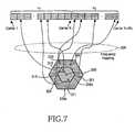
- Fig. 7is a view illustrating a sub-channel assigning method according to a third embodiment of the present invention.
- the BSis divided into the inner cell 200b and the outer cell 200a.
- the area divisionis made according to traffic load, not distance even though the division criterion is shown to be distance due to representational difficulty.
- the inner and outer cellscan be defined considering distance additionally.
- Available sub-channels (carriers)are divided into two different groups n 1 and n 2 .
- Frequencies within the frequency group n 2are assigned to MSs 301 to 304 in the outer cell 200a by frequency hopping 320.
- frequencies within the frequency group n 1are assigned to MSs 311,312 and 313 in the inner cell 200b by the frequency hopping 320.
- the loads of n 1 and n 2are controlled by adjusting the number of sub-channels in the respective sub-channel groups. If each sub-channel group has the same number of sub-channels, the load can be controlled by changing the number of users supported by the sub-channel group. In the case of a high average traffic, an optimum load for a high-load sub-channel group is about 1.0. When adjusting the load, the lowest of the SIRs of users using the high-load sub-channel group should be equal to or higher than the lowest of the SIRs of users using the low-load sub-channel group.
- ris a value obtained by dividing the distance between a BS and an MS by the half of the distance between the cell of the BS and its adjacent cell.
- dis the distance between the BS and the MS and c is a constant determined by a frequency and an environment, and a is a path loss exponent. If ⁇ is 2, the channel model is equivalent to a free space model.
- the SIR of an MS spaced from the BS by ris expressed as 1 r a 2 p [ ( 1 3 ⁇ r ) a + ( 1 3 + r 2 ⁇ 3 r ) a + ( 1 3 + r 2 + 3 r ) ⁇ ]
- a target SIRis s.
- N sub-channelsmust be arranged in the manner that maximizes p. If N sub-channels are available, N 1 sub-channels are assigned to users spaced from the BS by r or below and N 2 sub-channels are assigned to users spaced from the BS by a distance longer than r. Then, the loads are r 2 N P /N 1 and (1-r 2 )N P /N 2 , respectively. Computation of SIRs at the edges of the inner cell and the outer cell by Eq.
- r and N 1are determined such that values calculated by Eq. (5) and Eq. (6) are minimized and thus a minimum SIR is obtained. That is, optimization can be carried out in two ways.
- an x axisrepresents the quotient of dividing the distance between a BS and an MS by the distance between the BS and the remotest MS
- a y axisrepresents the quotient of dividing the number of sub-channels assigned to a high-load frequency hopping group by the number of entire sub-channels
- a z axisrepresents SIR.
- the SIR at the highest point of a curve 400is 50dB and the SIR at the lowest point of the curve 40 is -20dB.
- an x axisrepresents the quotient of dividing the distance between a BS and an MS by the distance between the BS and the remotest MS
- a y axisrepresents the quotient of dividing the number of sub-channels assigned to a high-load frequency hopping group by the number of entire sub-channels.
- the SIR of a curve 500 nearest to the originis 50dB
- the SIR of a curve 510 remotest from the originis -5dB.
- SIR gain changes with respect of the change of an average load as illustrated from Figs. 8 and 9are tabulated below.
- Loadis an overall average load
- Previous SIRis an SIR at a cell edge when the inventive sub-channel assignment is not applied
- Current SIRis an SIR at the cell edge when the inventive sub-channel assignment is applied.
- Gainis the difference between Previous SIR and Current SIR
- ris a value obtained by dividing the distance between a BS and an MS by the half of the distance between cells.
- N 1 /Nis obtained by dividing the number of sub-channels assigned to a high-load area by the number of entire sub-channels.
- Inner loadinner the load of a high-load area (in general, the load of a frequency hopping group assigned to a user within a cell). As noted from Table 1, the inventive sub-channel assignment brings an SIR gain of about 3dB.
- OFDM frequenciesare partitioned into a predetermined number of parts and each cell is divided into a near area and a remote area.
- a frequency reuse distance of 1is used and for the remote area, a different frequency reuse distance is used.
- frequency hoppingis adopted, frequencies are reused in the same manner except that each divided carrier index group has discontinuous carriers. Consequently, frequency utilization is increased.
Landscapes
- Engineering & Computer Science (AREA)
- Signal Processing (AREA)
- Computer Networks & Wireless Communication (AREA)
- Mobile Radio Communication Systems (AREA)
Description
- The present invention relates generally to a frequency reuse method in a mobile communication system, and in particular, to a frequency reuse method in an orthogonal frequency division multiplex (OFDM) mobile communication system.
- Mobile communication systems are designed to provide voice service, ensuring mobility for users. Owing to the drastic development of mobile communication technology and ever-increasing user demands, these mobile communication systems have been developed to additionally provide data service. Data transmission has been evolved from short messages to Internet service. Today, high-rate data transmission such as moving pictures is possible. Transmission schemes, developed from traditional cellular systems, are now under discussion for standardization in the 3rd generation partnership project (3GPP). The 3G mobile communication systems are categorized into synchronous code division multiple access (CDMA) and asynchronous CDMA.
- OFDM is a type of multi-carrier modulation. OFDM spread spectrum technology distributes data over multiple carriers spaced from each other with respect to a central frequency, thereby offering orthogonality between the carriers. The OFDM has excellent performance in a multi-path radio environment. For this reason, the OFDM attracts much interest as a suitable modulation scheme for digital terrestrial television service and digital audio broadcasting. Hence it is expected that the OFDM will be adopted as a digital television standard in Europe, Japan, and Australia and is currently envisioned for use in a fourth generation mobile communications system.
- For mobile communication applications, the OFDM has the following advantages.
- (1) The duration of a single transmission symbol is a multiple of the number of carriers, as compared to a single carrier scheme. If a guard interval is added, multi-path-caused transmission characteristic deterioration can be decreased.
- (2) In view of data distribution across the entire frequency band, the influence of interference in a particular frequency is limited to a limited number of data bits, and errors can be reduced by interleaving and error correction codes.
- (3) OFDM modulation waves are almost random noise. Thus, their effects on different services are equivalent to the influence of random noise.
- (4) The OFDM allows fast Fourier transform (FFT)-based modulation/demodulation.
- Because of the above-described and other benefits, many studies are being actively conducted on the OFDM.
- However, one base station (BS) can not use all of the available OFDM frequency channels in view of the orthogonality of frequencies used. If a total of 512 frequency channels are available and 4 or 32 frequency channels, here 4 frequency channels are assigned to one user, up to 128 resources are available to a BS. In the case where each BS is allowed to use the 128 resources, the same frequency resources may be used in different BSs. Supposing that there are BS A and BS B adjacent to BS A, both BSs may assign the same 4 channels to mobile stations (MSs) within their cells. If the MSs are near to each other, they experience deterioration of carrier-to-interference ratio (C/I) characteristics.
- To solve the problem, each BS adaptively assigns carriers according to interference. The BS assigns a higher priority to an unused frequency in an adjacent BS. It further prioritizes frequencies used in adjacent BSs according to distances between MSs within its cell and those within the adjacent cells. The BS assigns higher-priority frequencies before lower-priority ones.
- To make this scheme viable, the BS must predetermine the frequencies that adjacent BSs are using and calculate the distances between an MS being serviced within its cell and MSs being serviced within the adjacent cells. As a result, system complexity is increased.
- To avoid the constraints, cellular systems implement frequency reuse. Fig. 1 illustrates a conventional frequency reuse scheme with a frequency reuse distance of 3 in an OFDM cellular mobile communication system.
- Referring to Fig. 1, a complete frequency bandwidth is partitioned into three parts. A third of the bandwidth is available to each BS so that each of BSs 110 to 160 uses a different frequency from those of its adjacent BSs. For example, BS 100 uses a third of the carrier indexes and its adjacent BSs 120 to 160 use the other two thirds of carrier indexes. Similar system design occurs at the other BSs. Here, the frequency reuse distance is 3. In general, cellular systems implement frequency reuse with a longer frequency distance based on this principle.
- Despite the advantage of efficient and non-overlapped frequency use, the above conventional frequency reuse scheme has the distinctive shortcoming that the entire frequency bandwidth cannot be fully utilized in each cell. The number of channels available to a particular BS is the number of serviceable users or the data rates of services. Therefore, the decrease of the number of available channels limits the number of serviceable users or the data rates.
- EP 0 782 360 A1 discloses a system and method for a cellular wireless communications system wherein each cell is divided in an inner cell and an outer cell. Reuse partitioning of frequency resources is employed to minimize neighbor-channel interference.
- WO 02/ 49306 A2 discloses a method for subcarrier selection for a system employing orthogonal frequency division multiple access (OFDMA). Subcarriers are partitioned into a plurality of groups and each group comprises at least one cluster of subcarriers. A subscriber may indicate a selection of one or more groups. At least one cluster is then allocated for use in communication with the subscriber.
- US 5 953 661 discloses a system and method for operating a cellular communication system. Cells of said cellular communication system are divided into outer cells and inner cells. At least two frequency reuse patterns are assigned to the cells, one pattern to the outer cells and another, tighter pattern to the inner cells.
- It is, therefore, an object of the present invention to provide a method of increasing frequency reuse in an OFDM mobile communication system.
- It is another object of the present invention to provide a method of increasing frequency reuse without affecting the data performance of users in an OFDM mobile communication system.
- It is a further object of the present invention to provide a method of increasing the availability of frequency resources in an OFDM mobile communication system.
- The above objects are achieved by a frequency reuse method in an OFDM mobile communication system. Frequency resources available to each BS are divided into at least four frequency groups and a frequency reuse distance is set for each of the frequency groups. The frequency reuse distance set for each of the frequency group can be the same or different. The frequency groups are sequentially assigned to cell areas of each BS such that lower frequency groups are available to a near cell area and higher frequency resource groups are available to a remote cell area.
- Each of the frequency groups includes successive carriers. When frequency hopping is adopted, the frequency resources are divided into the at least four frequency groups according to frequency hopping patterns. At least one of the frequency groups is used with a frequency reuse distance of I in the near cell area. The near cell area is defined according to one of the distance from the BS, a system-required carrier-to-interference ratio (C/I), or interference from an adjacent BS. The at least four frequency groups are of the same size.
- To assign frequency resources to MSs in an OFDM mobile communication system, a BS, having first frequency resources for a near cell area and second frequency resources for a remote cell area, determines one of the distance between the BS and an MS, received signal strength, or interference from an adjacent BS, upon request of the MS for OFDM frequency setup. If a predetermined condition is satisfied, the BS establishes a channel with the MS by assigning a first OFDM frequency resource to the MS. If the MS is outside of the near cell area, the BS establishes a channel with the MS by assigning a second OFDM frequency resource to the MS.
- To assign OFDM frequency resources to MSs in an OFDM system having a plurality of BSs, each BS communicating with MSs in OFDM, having at least two sub-channel groups, and assigning OFDM frequency resources to an MS requesting a communication, the BS compares the SIR of an MS with a predetermined reference SIR, upon request for an OFDM frequency setup from the MS, and assigns OFDM frequency resources in a low sub-channel group to the MS if the SIR of the MS is lower than the reference SIR.
- If at least three sub-channel groups are set and at least two predetermined reference SIRs are used to discriminate the sub-channel groups, the BS assigns to the MS OFDM frequency resources in a sub-channel group corresponding to the lowest of reference SIRs higher than the SIR of the MS.
- The sub-channel group for the MS is determined according to the SIR and lognormal fading-including signal loss of the MS.
- The above and other objects, features and advantages of the present invention will become more apparent from the following detailed description when taken in conjunction with the accompanying drawings in which:
- Fig. 1 illustrates clusters of cells with a frequency reuse distance of 3 according to a conventional frequency reuse scheme in an OFDM cellular mobile communication system;
- Fig. 2 illustrates clusters of cells with two frequency reuse distances of 1 and 3 in an OFDM mobile communication system according to an embodiment of the present invention;
- Fig. 3 illustrates distance-based division of a cell area into a near area and a remote area according to the present invention;
- Fig. 4 is a graph illustrating block probability given by an Erlang B formula;
- Fig. 5 illustrates C/I or signal strength-based division of a cell area into a near area and a remote area according to the present invention;
- Fig. 6 illustrates clusters of cells with two frequency reuse distances of 1 and 3 in an OFDM mobile communication system adopting frequency hopping according to another embodiment of the present invention;
- Fig. 7 illustrates a method of assigning sub-channels to users according to a third embodiment of the present invention;
- Fig. 8 illustrates a mesh plot of SIRs at the edges of an inner cell and an outer cell under a load of 50%; and
- Fig. 9 illustrates a contour plot of the SIRs at the edges of the inner cell and the outer cell under the load of 50%.
- Preferred embodiments of the present invention will be described herein below with reference to the accompanying drawings. In the following description, well-known functions or constructions are not described in detail since they would obscure the invention in unnecessary detail.
- It is to be appreciated that while frequency reuse is implemented using two frequency reuse distances of 1 and 3 in the following description of the present invention, the number of frequency reuse distances is not limited. In fact, an OFDM frequency reuse distance can be 3, 4, 7, .... In addition, although hexagonal-shaped cells are artificial and such a shape cannot be generated in the real world, that is, each BS has a different shape of cell coverage, the ideal hexagonal cell shapes are assumed herein.
- Fig. 2 illustrates a frequency reuse scheme in an OFDM mobile communication system according to an embodiment of the present invention.
- Referring to Fig. 2, a given frequency bandwidth is partitioned into four carrier index groups n1 to n4 in order to obtain two frequency reuse distances of 3 and 1. If any other frequency reuse distances are adopted, the frequency bandwidth is partitioned into more or less parts. The reason for using the two frequency reuse distances is to achieve a satisfactory C/I at cell borders or cell edges when the frequency reuse distance of 3 is used. As the system requires a higher C/I level, or propagation loss and fading variance are great, a greater frequency reuse distance, should be used. In other words, the frequency reuse distance is varied according to the configuration of the BSs (i.e., propagation distance, propagation losses, fading variance, system-required C/I, and distance between BS and MS).
- A different frequency reuse distance is used according to the distance from a BS. OFDM carriers are assigned with a frequency reuse distance of 1 in a near cell area and with a frequency reuse distance of 3 in a remote cell area. The cell area can be divided according to C/I instead of the distance. In this case, the cell area is divided into a good channel-condition area and a bad channel-condition area. Since the C/I varies with the layout of buildings and the type of geographic terrain contour, the shapes of cell area coverages are different, which will be described later with reference to Fig. 5.
- The frequencies of carrier index group n1 are used in an area apart from each BS by a predetermined distance or less with a frequency reuse distance of 1. The areas are called "near areas (inner cells)" which are circular with respect to the
BSs 200 to 260. The remaining areas are called "remote areas (outer cells)." MSs within the near areas generally have good C/I characteristics. The distinction between the near areas and the remote areas can be made by system-required C/I and interference from adjacent BSs, instead of distance. - Fig. 3 illustrates a cell which is divided into a near area and a remote area according to distance from a BS in the present invention. Referring to Fig. 3, the
cell 200a of theBS 200 covers its signal propagation distance. The cell coverage is divided into anear area 200b with a radius r that is changed according to the characteristics and geographical features of theBS 200. The remaining area outside of the near area 2006 of the cell coverage is defined as a remote area. There is little interference from adjacent BSs within thenear area 200b. Thus, application of the frequency reuse distance of 1 to thenear area 200b does not affect MSs within other cells. - Returning to Fig. 2, OFDM frequencies are reused in the remote areas as done in the conventional frequency reuse scheme. As stated before, since hexagonal cells are assumed, OFDM frequencies are assigned to the remote areas of the
BSs 200 to 260 without overlapped areas. With a frequency reuse distance of 3, the carrier index groups n2, n3 and n4 are available to BSs 200 to 260. Thus, each BS assigns a channel to an MS in its remote area within resources assigned to the BS. For example, if the carrier index group n2 is available toBS 200,BS 200 assigns a channel within the available frequency band to an MS in its remote area. - If the MS is located in the near area of
BS 200,BS 200 assigns a channel within the carrier index group n1 to the MS. The same situation occurs within the other BSs all converge areas. That is, if the carrier index group n3 is available to BS 210, the BS 210 assigns a channel in the carrier index group n1 to an MS in its near area and a channel in the carrier index group n3 to an MS in its remote area, as illustrated in Fig. 2. - Fig. 5 illustrates a cell that is divided into a near area and a remote area according to signal strength or C/I in the present invention. The distance-based near
area 200b and a C/I-based near area 200C have different borders due to the channel condition betweenBS 200 and an MS, propagation loss, and the geographical features. While not shown,cell coverage 200a is also different in the real world for the same reason. For clarity of description, the near and remote areas are defined according to the distance from the BSs and the following description is also based on this assumption, even though the near and remote areas have different shapes depending on various factors. - In accordance with the first embodiment of the present invention, the complete frequency bandwidth is partitioned into a predetermined number of carrier index groups. One of the carrier index groups is used with a frequency reuse distance of 1 and the other carrier index groups, with a frequency reuse distance of 3. In case of non-hexagonal-shaped cell coverage, a frequency reuse distance higher than 3 should be used. Then the complete spectrum available is partitioned into (frequency reuse distance +1) parts. While the frequency bandwidth is equally partitioned in this embodiment, the divided carrier index groups may have different sizes considering the geographical features of the cells.
- Fig. 6 illustrates clusters of cells with frequency reuse distances of 1 and 3 in an OFDM mobile communication system using frequency hopping according to another embodiment of the present invention.
- While the complete spectrum is partitioned into the carrier index group n1 for a frequency reuse distance of 1 and the carrier index groups n2, n3 and n4 for a frequency reuse distance of 3 and each carrier index group has successive carriers in the first embodiment, each carrier index group consists of discontinuous carriers in the second embodiment.
- Referring to Fig. 6, to improve frequency diversity, the complete spectrum is partitioned into three carrier index groups, G1, G2 and G3. Each carrier index group includes carriers spaced from each other by a predetermined bandwidth. In the OFDM system using orthogonal frequency hopping, the carrier index groups G1, G2 and G3 are formed according to frequency hopping patterns. Using these carrier groups, different frequency reuse distances are achieved. The carrier group G1 is used in the near areas of
BSs 200 to 260 with a frequency reuse distance of 1 and the carrier groups G1, G2 and G3 are used in the remote areas with a frequency reuse distance of 3. The use of frequency hopping effects interference averaging. Therefore, the near areas with the frequency reuse distance of 1 can be widened. As stated before, the near areas are defined according to the distance from the BS or system-required C/I. - Now a description will be made of deriving a cost function on the following suppositions to implement the present invention in an optimizing way.
- 1. Users are distributed uniformly across a cell and the number of users is determined by an average Poisson process.
- 2. Cell radius is standardized to 1. A user in a near area with a radius r satisfies system-required frame error rate (FER) even if a frequency reuse distance is set to 1. A user apart from the BS by a distance between r and I satisfies the FER requirement when the frequency reuse distance is 3. All cells are of circular shapes. In this case, the average number of users in the near area is r2 and that of users outside the near area is 1-r2. These are identified as separate Poisson processes.
- 3. If a total of N OFDM carriers are available and M carriers are assigned to each user, the number of available resources is n(=N/M). For an area with a frequency reuse distance of 1, n1 resources are used and for an area with a frequency reuse distance of 3, n2 resources are used. Then, n=n1+3n2. To optimize n1 and n2, the sum of blocking rates is used as the cost function.
- 4. If no buffers are used in the OFDM system, n1 servers and n2 servers are required and traffic generations rates for n1 and n2 are R2 and (1-R2), respectively.
- On the above suppositions, the blocking probability is given by a known Erlang B formula, expressed as

- The Erlang B formula is represented as a graph illustrated in Fig. 4. Referring to Fig. 4, the blocking probability is always positive and the graph is given as a downwards convex parabola. Therefore, the cost is minimized at the apex of the parabola (i.e., zero differential of the cost function).
- The use of the single
frequency reuse distance 1 will be compared with the use of the different frequency reuse distances 1 and 3 in combination. - The blocking probability for the frequency reuse distance of 3 is

- In accordance with the present invention, n channels are divided into a greater number of sub-channels than in the conventional frequency reuse scheme by further defining an area with the frequency reuse distance of 1. As a result, the number of channels available specifically to each BS is decreased. Yet, if the frequency bandwidth (except the carriers) available commonly to all BSs is partitioned into three parts, n1+n2 frequencies are eventually available to each BS. Hence, the total number of carriers available to each BS is increased in effect. This was simulated as follows.
- The total number of OFDM frequencies is 512 and 4 or 32 channels are available to one user. The total number of available resources is then 128. System load is the ratio of traffic generated per unit time to the total number of available channels. If r is between 0.3 and 0.4 for the frequency reuse distance of 1, the blocking probability is less than that when the frequency reuse distance is 3. If r is increased to 0.9 and the blocking probability is fixed to 0.02, the BS capacity is four times greater than that when the frequency reuse distance is 3.
- Frequency resources are assigned to an MS according to one of the distance between the MS and a BS, received signal strength, or interference from adjacent BSs. While the given bandwidth is partitioned into (frequency reuse distance +1) parts, it can be partitioned into more parts. In addition, while the frequency resources are classified into two types, it is obvious that they can be divided into more types.
- As described before, when the frequency resources are classified into two types, frequencies in different carrier groups are assigned to an MS in a near area and an MS in a remote area, respectively.
- The frequency resources of two types can be assigned to MSs according to received signal strength, or interference from other adjacent BSs. In the case where the frequency resources are classified into more types, MSs are sorted according to the above criteria and the frequency resources are assigned correspondingly
- Only the distance between a BS and an MS is considered in the above sub-channel assignment. In a real environment, however, it is preferable to assign a sub-channel group with a relatively low load to a user experiencing the greatest path loss involving lognormal fading. Alternatively, if the SIRs (Signal-to-Interference Ratios) of users are known, it is also preferable to assign a sub-channel with a relatively low load to a user having the lowest SIR. On the assumption that sub-channels are divided into a small path loss group and a great path loss group, sub-channels are assigned to users according to a predetermined reference SIR and the SIRs of the users.
- In the case of three sub-channel groups, two or more predetermined reference SIRs are needed to distinguish the sub-channel groups. In this case, OFDM frequency resources in a sub-channel group having the lowest of reference SIRs higher than the SIR of an MS are assigned to the MS.
- Hereinbelow, a description is made of a method of assigning sub-channels according to path loss involving lognormal fading and a method of assigning sub-channels according to the SIRs of users.
- In general, since an MS near to a BS is remote from adjacent cells, the resulting low signal interference leads to a sufficiently high SIR. In this case, even if traffic load is great, the MS has a substantially low error rate. However, as the MS moves farther from the BS, the channel interference from the adjacent cells increases, resulting in a lower SIR. Therefore, the interference should be reduced for the MS.
- For the purpose, sub-channels are divided into two or more groups relying on the above principle in the present invention. The SIR is improved by assigning sub-channels according to traffic load, instead of distance. Hence, the respective sub-channel groups are assigned to users having different traffic loads, which will be described with reference to Fig. 7. Fig. 7 is a view illustrating a sub-channel assigning method according to a third embodiment of the present invention.
- Referring to Fig. 7, the BS is divided into the
inner cell 200b and theouter cell 200a. The area division is made according to traffic load, not distance even though the division criterion is shown to be distance due to representational difficulty. In reality, the inner and outer cells can be defined considering distance additionally. Available sub-channels (carriers) are divided into two different groups n1 and n2. Frequencies within the frequency group n2 are assigned toMSs 301 to 304 in theouter cell 200a by frequency hopping 320. Similarly, frequencies within the frequency group n1 are assigned to MSs 311,312 and 313 in theinner cell 200b by the frequency hopping 320. - While two sub-channel groups have been set according to traffic load for notational simplicity, the number of sub-channel groups can be 3 or more. Use of an appropriate number of sub-channel groups according to system environment improves efficiency.
- The loads of n1 and n2 are controlled by adjusting the number of sub-channels in the respective sub-channel groups. If each sub-channel group has the same number of sub-channels, the load can be controlled by changing the number of users supported by the sub-channel group. In the case of a high average traffic, an optimum load for a high-load sub-channel group is about 1.0. When adjusting the load, the lowest of the SIRs of users using the high-load sub-channel group should be equal to or higher than the lowest of the SIRs of users using the low-load sub-channel group.
- A channel model for the load-based sub-channel assignment and its efficiency will now be described below.
- r is a value obtained by dividing the distance between a BS and an MS by the half of the distance between the cell of the BS and its adjacent cell. And a channel between the BS and the MS is modeled as

where d is the distance between the BS and the MS and c is a constant determined by a frequency and an environment, and a is a path loss exponent. If α is 2, the channel model is equivalent to a free space model. The SIR of an MS spaced from the BS by r is expressed as
- On the assumption of a circular cell, the average of packets generated is proportional to area, and the load of the cell is p, r2NP packets are generated within a circle spaced from the BS by a normalized distance as the radius of the circle, r and (1-r2)NP packets are generated outside the circle. Here, a target SIR is s.
- Now, sub-channels must be arranged in the manner that maximizes p. If N sub-channels are available, N1 sub-channels are assigned to users spaced from the BS by r or below and N2 sub-channels are assigned to users spaced from the BS by a distance longer than r. Then, the loads are r2NP/N1 and (1-r2)NP/N2, respectively. Computation of SIRs at the edges of the inner cell and the outer cell by Eq. (4) is represented as


- Therefore, a maximum cell load p higher than the target SIR s, calculated by Eq. (5) and Eq. (6), is a maximum system capacity. On the other hand, with p given, r and N1 are determined such that values calculated by Eq. (5) and Eq. (6) are minimized and thus a minimum SIR is obtained. That is, optimization can be carried out in two ways.
- In view of non-linearity of Eq. (5) and Eq. (6) with respect to r and N1, the optimization is done graphically. For example, with α fixed to 4 and r and N1/N used as variables, SIR is graphed as illustrated in Figs. 8 and 9. Fig. 8 illustrates a mesh plot of SIRs at the edges of the inner cell and the outer cell when the loads are 50% and Fig. 9 illustrates a contour plot of the SIRs at the edges of the inner cell and the outer cell when the loads are 50%.
- Referring to Fig. 8, an x axis represents the quotient of dividing the distance between a BS and an MS by the distance between the BS and the remotest MS, a y axis represents the quotient of dividing the number of sub-channels assigned to a high-load frequency hopping group by the number of entire sub-channels, and a z axis represents SIR. The SIR at the highest point of a
curve 400 is 50dB and the SIR at the lowest point of thecurve 40 is -20dB. - Referring to Fig. 9, an x axis represents the quotient of dividing the distance between a BS and an MS by the distance between the BS and the remotest MS, and a y axis represents the quotient of dividing the number of sub-channels assigned to a high-load frequency hopping group by the number of entire sub-channels. The SIR of a
curve 500 nearest to the origin is 50dB, and the SIR of acurve 510 remotest from the origin is -5dB. SIR gain changes with respect of the change of an average load as illustrated from Figs. 8 and 9 are tabulated below.(Table 1) Load Previous SIR Current SIR Gain r N1/N Inner load 0.7 -7dB -3.85dB 3.15dB 0.885 0.565 0.97 0.5 -5.5dB -2.15dB 3.35dB 0.885 0.415 0.88 0.3 -3.3dB 0.08dB 3.4dB 0.83 0.32 0.65 0.1 1.45dB 4.dB 3.1dB 0.84 0.33 0.21 - In Table 1, Load is an overall average load, Previous SIR is an SIR at a cell edge when the inventive sub-channel assignment is not applied, and Current SIR is an SIR at the cell edge when the inventive sub-channel assignment is applied. Gain is the difference between Previous SIR and Current SIR, and r is a value obtained by dividing the distance between a BS and an MS by the half of the distance between cells. N1/N is obtained by dividing the number of sub-channels assigned to a high-load area by the number of entire sub-channels. Inner load inner the load of a high-load area (in general, the load of a frequency hopping group assigned to a user within a cell). As noted from Table 1, the inventive sub-channel assignment brings an SIR gain of about 3dB.
- In accordance with the present invention, OFDM frequencies are partitioned into a predetermined number of parts and each cell is divided into a near area and a remote area. For the near area, a frequency reuse distance of 1 is used and for the remote area, a different frequency reuse distance is used. When frequency hopping is adopted, frequencies are reused in the same manner except that each divided carrier index group has discontinuous carriers. Consequently, frequency utilization is increased.
- While the invention has been shown and described with reference to certain preferred embodiments thereof, it will be understood by those skilled in the art that various changes in form and details may be made therein without departing from the scope of the invention as defined by the appended claims.


Claims (19)
- Frequency reuse method in an orthogonal frequency division multiplex, OFDM, mobile communication system having a plurality of base stations, BS (200), comprising the steps of:dividing frequency resources available to each BS (200) into at least four frequency groups (n1, n2, n3, n4) and setting a frequency distance for each of the frequency groups (n1, n2, n3, n4); andsequentially assigning the frequency groups (n1, n2, n3, n4) to cell areas of each BS (200) such that lower frequency groups are available to a near cell area (200b) and higher frequency groups are available to a remote cell area (200a),characterized in that at least one of the frequency groups (n1, n2, n3, n4) is used with a frequency reuse distance of 1 in the near cell area (200b).
- Method according to claim 1, wherein each of the frequency groups (n1, n2, n3, n4) includes successive carriers.
- Method according to claim 1, wherein when frequency hopping is adopted, the frequency resources are divided into the at least four frequency groups (G1, G2, G3) according to frequency hopping patterns.
- Method according to claim 1, wherein the near cell area (200b) is defined according to a distance from the BS (200).
- Method according to claim 1, wherein the near cell area (200b) is defined according to a system-required carrier-to-interference ratio, C/I.
- Method according to claim 5, wherein the near cell area (200b) is defined according to interference from an adjacent BS (200).
- Method according to claim 1, wherein the at least four frequency groups (n1, n2, n3, n4) are of the same size.
- Method according to claim 1, wherein a frequency group (n1, n2, n3, n4) assigned to the near cell area (200b) satisfies

where n1 and n2 are the numbers of frequency resources available to the near cell area (200b) and the remote cell area (200a), respectively, λ1 and λ2 are the probabilities of generating an event in the near area (200b) and the remote area (200a), respectively, and j is a parameter for summation. - Method according to claim 8, wherein the other frequency groups (n1, n2, n3, n4) are of the same size and assigned to the remote cell area (200a).
- Method according to any of claims I - 9, the method further comprising assigning frequency resources to mobile stations, MS (301, 311), in the base station BS (200) having first frequency resources for the near cell area (200b) and second frequency resources for the remote cell area (200a) in the orthogonal frequency division multiplex OFDM mobile communication system, the method comprising the steps of:determining a predetermined condition between the BS (200) and one of the MS (301,311) upon request of the MS (301, 311) for OFDM frequency setup;establishing a channel with the MS (301, 311) by assigning a first OFDM frequency resource to the MS (301, 311) if the predetermined condition is satisfied; andestablishing a channel with the MS (301, 311) by assigning a second OFDM frequency resource to the MS (301, 311) if the MS (301, 311) is outside of the near cell area (200b).
- Method according to claim 10, wherein the predetermined condition is the distance between the BS (200) and the MS (301, 311).
- Method according to claim 10, wherein the predetermined condition is the level of interference experienced by the MS (301, 311) from an adjacent BS (200).
- Method according to claim 10, wherein the predetermined condition is the strength of a received signal between the MS (301, 311) and the BS (200).
- Method according to any of claims 1 - 9, the method further comprising assigning orthogonal frequency division multiplex OFDM frequency resources to mobile stations, MSs (301, 311) in the base station BS (200) in the OFDM system having a plurality of BSs (200), each BS (200) communicating with MSs (301, 311) in OFDM having at least two sub-channel groups, and assigning OFDM frequency resources to one of the MS (301, 311) requesting a communication, the method comprising the steps of:comparing the signal to interference ratio, SIR, of an MS (301, 311) with a predetermined reference SIR, upon request for an OFDM frequency setup from the MS (301,311); andassigning OFDM frequency resources in a low sub-channel group to the MS (301, 311) if the SIR of the MS (301, 311) is lower than the reference SIR.
- Method according to claim 14, wherein if at least three sub-channel groups are set and at least two predetermined reference SIRs are used to discriminate the sub-channel groups, OFDM frequency resources in a sub-channel group corresponding to the lowest of reference SIRs higher than the SIR of the MS (301, 311) are assigned to the MS (301,311).
- Method according to claim 14, wherein the sub-channel group for the MS (301, 311) is determined according to the SIR and lognormal fading-including signal loss of the MS (301, 311).
- Method according to claim 16, wherein a low-load sub-channel group is assigned to the MS (301, 311) if the MS (301, 311) has a great lognormal fading value.
- Method according to claim 14, wherein the BS (200) hops OFDM frequencies in the sub-channel group for the MS (301,311) during communication with the MS (301, 311) according to a preset frequency hopping rule.
- Method according to any of claims 1 - 9, the method further comprising assigning orthogonal frequency division multiplex OFDM frequency resources to mobile stations, MSs (301, 311), in the base station BS (200) in an OFDM system having a plurality of BSs (200), each BS (200) communicating with MSs (301, 311) in OFDM, having at least two sub-channel groups, and assigning OFDM frequency resources to one of the MS (301, 311) requesting a communication, the method comprising the steps of:assigning, upon request for an OFDM frequency setup from an MS (301, 311), to the MS (301,311) OFDM frequency resources in a sub-channel group that maximizes load p in Equation (10) and Equation (11), when a channel is modeled as Equation (8) and the average signal to interference ratio, SIR, of an MS (301, 311) spaced from the BS (200) by a distance r is calculated by Equation (9),where d is the distance between the BS (200) and the MS (301, 311), c is a constant determined by a frequency and an environment, α is a path loss exponent, p is a cell load, N is the number of entire sub-channels, and N1 is the number of sub-channels assigned to an inner cell (200b).


Applications Claiming Priority (4)
| Application Number | Priority Date | Filing Date | Title |
|---|---|---|---|
| KR2002068830 | 2002-11-07 | ||
| KR20020068830 | 2002-11-07 | ||
| KR1020030075845AKR20040041009A (en) | 2002-11-07 | 2003-10-29 | Frequency reuse method of orthogonal frequency division multiplex in mobile communication system |
| KR2003075845 | 2003-10-29 |
Publications (2)
| Publication Number | Publication Date |
|---|---|
| EP1418776A1 EP1418776A1 (en) | 2004-05-12 |
| EP1418776B1true EP1418776B1 (en) | 2006-03-22 |
Family
ID=32109575
Family Applications (1)
| Application Number | Title | Priority Date | Filing Date |
|---|---|---|---|
| EP20030078518Expired - LifetimeEP1418776B1 (en) | 2002-11-07 | 2003-11-07 | Frequency reuse method in an orthogonal frequency division multiplex mobile communication system (OFDM) |
Country Status (5)
| Country | Link |
|---|---|
| US (1) | US20040097238A1 (en) |
| EP (1) | EP1418776B1 (en) |
| JP (2) | JP2004159345A (en) |
| CN (1) | CN1503486A (en) |
| DE (1) | DE60304104T2 (en) |
Cited By (11)
| Publication number | Priority date | Publication date | Assignee | Title |
|---|---|---|---|---|
| WO2008001977A1 (en)* | 2006-06-26 | 2008-01-03 | Electronics And Telecommunications Research Institute | Transmission method and apparatus for allocating subchannel and forming stationary beam to maximize transmission efficiency in orthogonal frequency division multiplexing /multiple access based wireless communication system |
| US8463312B2 (en) | 2009-06-05 | 2013-06-11 | Mindspeed Technologies U.K., Limited | Method and device in a communication network |
| US8559998B2 (en) | 2007-11-05 | 2013-10-15 | Mindspeed Technologies U.K., Limited | Power control |
| US8712469B2 (en) | 2011-05-16 | 2014-04-29 | Mindspeed Technologies U.K., Limited | Accessing a base station |
| US8798630B2 (en) | 2009-10-05 | 2014-08-05 | Intel Corporation | Femtocell base station |
| US8849340B2 (en) | 2009-05-07 | 2014-09-30 | Intel Corporation | Methods and devices for reducing interference in an uplink |
| US8862076B2 (en) | 2009-06-05 | 2014-10-14 | Intel Corporation | Method and device in a communication network |
| US8904148B2 (en) | 2000-12-19 | 2014-12-02 | Intel Corporation | Processor architecture with switch matrices for transferring data along buses |
| US9042434B2 (en) | 2011-04-05 | 2015-05-26 | Intel Corporation | Filter |
| US9107136B2 (en) | 2010-08-16 | 2015-08-11 | Intel Corporation | Femtocell access control |
| WO2016010167A1 (en)* | 2014-07-15 | 2016-01-21 | 엘지전자 주식회사 | Resource allocation method and signal processing method of terminal |
Families Citing this family (100)
| Publication number | Priority date | Publication date | Assignee | Title |
|---|---|---|---|---|
| US7042857B2 (en) | 2002-10-29 | 2006-05-09 | Qualcom, Incorporated | Uplink pilot and signaling transmission in wireless communication systems |
| JP3860556B2 (en)* | 2003-04-04 | 2006-12-20 | 松下電器産業株式会社 | Base station apparatus and communication method |
| US7177297B2 (en) | 2003-05-12 | 2007-02-13 | Qualcomm Incorporated | Fast frequency hopping with a code division multiplexed pilot in an OFDMA system |
| KR100965338B1 (en)* | 2003-08-18 | 2010-06-22 | 엘지전자 주식회사 | Subcarrier Allocation Method for Inter-cell Interference Reduction in PFDMA Cellular Environment |
| DE10338053B4 (en)* | 2003-08-19 | 2005-12-15 | Siemens Ag | Method for allocating radio resources and network equipment in a multicarrier radio communication system |
| US7957359B1 (en)* | 2003-11-19 | 2011-06-07 | Nortel Networks Limited | Method of resource allocation in a multiple access wireless communications network |
| US8611283B2 (en) | 2004-01-28 | 2013-12-17 | Qualcomm Incorporated | Method and apparatus of using a single channel to provide acknowledgement and assignment messages |
| KR100724989B1 (en)* | 2004-04-14 | 2007-06-04 | 삼성전자주식회사 | Power control apparatus and method in a communication system using orthogonal frequency division multiple access |
| EP1603356B1 (en) | 2004-05-31 | 2011-09-28 | Samsung Electronics Co., Ltd. | Resource allocation method for a cellular communication system |
| US7697618B2 (en) | 2004-06-09 | 2010-04-13 | Alcatel-Lucent Usa Inc. | Multiplexing scheme for an orthogonal frequency division multiplexing system |
| US9294218B2 (en)* | 2004-07-16 | 2016-03-22 | Qualcomm Incorporated | Rate prediction in fractional reuse systems |
| US8891349B2 (en) | 2004-07-23 | 2014-11-18 | Qualcomm Incorporated | Method of optimizing portions of a frame |
| CN1994011B (en)* | 2004-07-28 | 2013-04-10 | 日本电气株式会社 | Wireless transmission system |
| FI20045368A0 (en)* | 2004-10-01 | 2004-10-01 | Nokia Corp | Frequency allocation in a telecommunications network |
| CN101951679B (en) | 2004-10-19 | 2013-08-21 | 夏普株式会社 | Base station apparatus, wireless communication system, and wireless transmission method |
| CN100353803C (en)* | 2004-11-04 | 2007-12-05 | 华为技术有限公司 | Networking method for OFDMA system |
| KR100703442B1 (en) | 2004-11-12 | 2007-04-03 | 삼성전자주식회사 | Handover Method and System in Broadband Wireless Access Communication System |
| KR100881783B1 (en)* | 2004-11-30 | 2009-02-03 | 한국과학기술원 | Frequency resource allocation device and method in communication system |
| CN1783861B (en)* | 2004-12-01 | 2011-04-13 | 华为技术有限公司 | Method for realizing frequency soft multiplexing in radio communication system |
| JP4552635B2 (en)* | 2004-12-07 | 2010-09-29 | 日本電気株式会社 | Multi-carrier transmission apparatus and multi-carrier transmission method |
| EP1820360B1 (en)* | 2004-12-08 | 2013-02-27 | Electronics and Telecommunications Research Institute | Method of controlling base stations to suppress inter-cell interference |
| US8831115B2 (en)* | 2004-12-22 | 2014-09-09 | Qualcomm Incorporated | MC-CDMA multiplexing in an orthogonal uplink |
| US8238923B2 (en) | 2004-12-22 | 2012-08-07 | Qualcomm Incorporated | Method of using shared resources in a communication system |
| US8144658B2 (en)* | 2005-02-11 | 2012-03-27 | Qualcomm Incorporated | Method and apparatus for mitigating interference in a wireless communication system |
| CN101116363A (en)* | 2005-02-18 | 2008-01-30 | 三菱电机株式会社 | Multi-band wireless communication method and base station |
| KR100966044B1 (en)* | 2005-02-24 | 2010-06-28 | 삼성전자주식회사 | Frequency Resource Allocation System and Method in Multi-Cell Communication Systems |
| KR20060097450A (en)* | 2005-03-09 | 2006-09-14 | 삼성전자주식회사 | System and method for resource allocation control in multi-cell communication system |
| WO2006126616A1 (en) | 2005-05-26 | 2006-11-30 | Matsushita Electric Industrial Co., Ltd. | Wireless communication base station apparatus and wireless communication method |
| JP5118026B2 (en) | 2005-06-15 | 2013-01-16 | ホアウェイ・テクノロジーズ・カンパニー・リミテッド | Communication resource allocation method and system |
| DE602005015721D1 (en) | 2005-06-15 | 2009-09-10 | Alcatel Lucent | Uplink interference coordination method in monofrequency networks, base station and mobile network therefor |
| KR100965677B1 (en)* | 2005-08-22 | 2010-06-24 | 삼성전자주식회사 | Resource Allocation Method and Received Resource in Cellular-based Wireless Communication System Using Multicarrier |
| US20070077934A1 (en)* | 2005-09-30 | 2007-04-05 | Aik Chindapol | Dynamic reuse partitioning and subchannel allocation scheme in multicell OFDMA downlink systems |
| US8774019B2 (en)* | 2005-11-10 | 2014-07-08 | Apple Inc. | Zones for wireless networks with relays |
| CN1996806A (en)* | 2006-01-06 | 2007-07-11 | 北京三星通信技术研究有限公司 | Device and method for data transfer in the competitive resource of the wireless communication system |
| JP2007194755A (en)* | 2006-01-18 | 2007-08-02 | Nec Corp | Allocation system for wireless resource and method thereof, and base station used for the same, and program |
| KR20080104026A (en)* | 2006-02-27 | 2008-11-28 | 닛본 덴끼 가부시끼가이샤 | Method of reducing interference between mobile communication system, base station and cell |
| EP1999982B1 (en) | 2006-03-20 | 2018-08-29 | BlackBerry Limited | Method&system for fractional frequency reuse in a wireless communication network |
| EP1838116A1 (en)* | 2006-03-22 | 2007-09-26 | Matsushita Electric Industrial Co., Ltd. | Neigboring cell interference management in a SC-FDMA system |
| CN100568996C (en)* | 2006-03-28 | 2009-12-09 | 华为技术有限公司 | Wireless Cellular Network and Its Middle Frequency Band Allocation Method |
| CN100558183C (en)* | 2006-03-29 | 2009-11-04 | 华为技术有限公司 | A method for reallocating wireless resources at cell edge |
| CN100413350C (en)* | 2006-03-30 | 2008-08-20 | 华为技术有限公司 | Resource reallocation method and device in wireless evolution network |
| JP2007274042A (en)* | 2006-03-30 | 2007-10-18 | Fujitsu Ltd | Communication device |
| EP1993306A1 (en)* | 2006-03-31 | 2008-11-19 | Panasonic Corporation | Radio communication base station device and radio communication mobile station device |
| CN101043499B (en)* | 2006-04-14 | 2011-06-22 | 华为技术有限公司 | Method and device for capturing signals transmitted on a channel in an OFDM system |
| CN1845633B (en)* | 2006-05-11 | 2011-08-10 | 北京邮电大学 | Frequency multiplexing method based on wireless cellular network |
| US9071321B2 (en) | 2006-05-31 | 2015-06-30 | Apple Inc. | Methods and system for wireless networks with relays involving pseudo-random noise sequences |
| US8229444B2 (en)* | 2006-07-13 | 2012-07-24 | Nec Corporation | Cellular system, carrier allocation method thereof, base station, and mobile station |
| WO2008007437A1 (en) | 2006-07-14 | 2008-01-17 | Fujitsu Limited | Mobile communication system and base station |
| JP2008042547A (en)* | 2006-08-07 | 2008-02-21 | Fujitsu Ltd | Mobile communication system, base station, terminal device, and transmission control method |
| JP2008048148A (en)* | 2006-08-16 | 2008-02-28 | Nec Corp | Mobile communication system, its frequency assigning method, and base station used therefor |
| US8223625B2 (en)* | 2006-08-23 | 2012-07-17 | Qualcomm, Incorporated | Acquisition in frequency division multiple access systems |
| WO2008026867A1 (en)* | 2006-09-01 | 2008-03-06 | Posdata Co., Ltd. | Frequency reusing method in wireless communication system and radio access station system for the same |
| CN101141796B (en)* | 2006-09-08 | 2010-12-08 | 华为技术有限公司 | Uplink Resource Multiplexing Method in Wireless Relay System |
| CN101518114B (en)* | 2006-09-20 | 2012-03-21 | 日本电气株式会社 | Carrier assignment method for cellular system, cellular system, base station, and mobile station |
| WO2008050230A2 (en)* | 2006-10-27 | 2008-05-02 | Nokia Corporation | Method and apparatus for handover measurement |
| EP1926332B1 (en)* | 2006-11-24 | 2009-02-11 | Alcatel Lucent | Communication method, base station, and user terminal for a wireless communication network |
| JP5156334B2 (en)* | 2006-12-04 | 2013-03-06 | 株式会社エヌ・ティ・ティ・ドコモ | Wireless communication apparatus and wireless communication method |
| US8483038B2 (en) | 2006-12-04 | 2013-07-09 | Ntt Docomo, Inc. | Radio communication apparatus and radio communication method |
| US20080159249A1 (en)* | 2006-12-21 | 2008-07-03 | Ntt Docomo, Inc. | Radio communication apparatus and radio communication method |
| JP4460598B2 (en)* | 2006-12-21 | 2010-05-12 | 株式会社エヌ・ティ・ティ・ドコモ | Wireless communication apparatus and wireless communication method |
| CN101242640B (en)* | 2007-02-08 | 2011-07-27 | 鼎桥通信技术有限公司 | Inter-cell interference restraint method, base station and system for restraining inter-cell interference |
| EP2117242A4 (en)* | 2007-02-28 | 2013-01-02 | Fujitsu Ltd | WIRELESS COMMUNICATION SYSTEM, TERMINAL, AND COMMUNICATION METHOD |
| KR20080080731A (en)* | 2007-03-02 | 2008-09-05 | 삼성전자주식회사 | Apparatus and Method for Frequency Reuse in Multiple Input Multiple Output Systems |
| KR101002885B1 (en)* | 2007-04-03 | 2010-12-21 | 연세대학교 산학협력단 | Apparatus and Method for Allocating Frequency Resource in Communication System |
| US8121085B1 (en)* | 2007-05-10 | 2012-02-21 | Marvell International Ltd. | Slot allocation method and apparatus for slot-based communication |
| EP2190233A4 (en) | 2007-08-17 | 2013-04-24 | Fujitsu Ltd | A RESOURCE ASSIGNMENT METHOD IN A WIRELESS BASE STATION DEVICE, AND A WIRELESS BASE STATION DEVICE |
| EP2191669A4 (en)* | 2007-08-21 | 2016-11-16 | Unwired Planet Internat Ltd | A multi carrier frequency assignment method |
| CN101388697B (en)* | 2007-09-10 | 2013-02-27 | 中兴通讯股份有限公司 | Method for randomizing neighborhood cell interference in OFDM system |
| KR100936696B1 (en)* | 2007-11-16 | 2010-01-13 | 고려대학교 산학협력단 | Bandwidth Distributed Resource Allocation Method and Device in Orthogonal Frequency Division Multiple Access System |
| JP5282738B2 (en)* | 2007-12-04 | 2013-09-04 | 富士通株式会社 | Scheduling method, radio base station, and radio terminal |
| JP5115179B2 (en) | 2007-12-20 | 2013-01-09 | 日本電気株式会社 | Wireless communication control device, wireless communication control system, wireless communication control method, wireless communication control program, and recording medium |
| IL188754A (en) | 2008-01-14 | 2012-10-31 | Mariana Goldhamer | Wireless communication frames for improved intra-system coexistence |
| JP5088149B2 (en) | 2008-01-17 | 2012-12-05 | 富士通株式会社 | Scheduling method and radio base station |
| GB2456572B (en)* | 2008-01-18 | 2012-03-14 | Picochip Designs Ltd | Femtocell device |
| KR20100113137A (en)* | 2008-02-08 | 2010-10-20 | 미쓰비시덴키 가부시키가이샤 | Method for allocating bandwidth from radio frequency spectrum in cellular network including set of cells |
| US8238367B1 (en) | 2008-03-27 | 2012-08-07 | Marvell International Ltd. | Slot allocation, user grouping, and frame partition method for H-FDD systems |
| JP5200701B2 (en)* | 2008-07-02 | 2013-06-05 | 富士通株式会社 | Base station apparatus, frequency allocation method, mobile communication system, and communication apparatus |
| JP5168018B2 (en) | 2008-08-04 | 2013-03-21 | 富士通株式会社 | Frequency allocation method in radio base station apparatus and radio base station apparatus |
| US8687545B2 (en) | 2008-08-11 | 2014-04-01 | Qualcomm Incorporated | Anchor carrier in a multiple carrier wireless communication system |
| CN102144425B (en)* | 2008-09-05 | 2014-02-19 | Nec欧洲有限公司 | Fractional frequency reuse in OFDMA |
| CN101674680A (en)* | 2008-09-10 | 2010-03-17 | 华为技术有限公司 | Method and device for allocating bands and base station |
| EP2352241A4 (en)* | 2008-11-21 | 2014-12-24 | Fujitsu Ltd | BASIC STATION, COMMUNICATION PROCEDURE, SUBSCRIPTION PROCEDURE AND SUBSCRIPTION PROGRAM |
| JP5356541B2 (en)* | 2009-02-05 | 2013-12-04 | エルジー エレクトロニクス インコーポレイティド | Method and apparatus for transmitting uplink control signal in wireless communication system |
| US8483150B2 (en) | 2009-02-05 | 2013-07-09 | Lg Electronics Inc. | Method and apparatus of transmitting uplink control signal in wireless communication system |
| KR101652864B1 (en)* | 2009-02-19 | 2016-08-31 | 삼성전자주식회사 | Multi-cell network including communication device of schedulling outer cell frequency resource |
| JP5150539B2 (en)* | 2009-03-18 | 2013-02-20 | 株式会社Kddi研究所 | Base station control apparatus and base station cooperative communication control method |
| JP5150544B2 (en)* | 2009-03-27 | 2013-02-20 | 株式会社Kddi研究所 | Base station control apparatus and base station control method |
| JP5280528B2 (en)* | 2009-05-27 | 2013-09-04 | Kddi株式会社 | Frequency allocation apparatus and program |
| JP5526803B2 (en)* | 2009-05-29 | 2014-06-18 | ソニー株式会社 | COMMUNICATION DEVICE, COMMUNICATION CONTROL METHOD, AND PROGRAM |
| CN101938747B (en)* | 2009-07-01 | 2013-12-04 | 中兴通讯股份有限公司 | Method and device for transmitting and receiving resource metric |
| JP5304545B2 (en) | 2009-08-28 | 2013-10-02 | 富士通株式会社 | Base station apparatus and communication method |
| US20110250846A1 (en)* | 2010-04-12 | 2011-10-13 | Nokia Corporation | Apparatus and associated methods |
| US8477642B2 (en) | 2010-04-21 | 2013-07-02 | Qualcomm Incorporated | Ranging and distance based spectrum selection in cognitive radio |
| US8792326B2 (en) | 2010-04-26 | 2014-07-29 | Qualcomm Incorporated | Ranging and distance based wireless link spectrum selection |
| WO2011148836A1 (en)* | 2010-05-28 | 2011-12-01 | 日本電気株式会社 | Wireless resource setting method, wireless communication system, wireless base state, and program |
| GB2489716B (en) | 2011-04-05 | 2015-06-24 | Intel Corp | Multimode base system |
| GB2491362B (en)* | 2011-05-31 | 2015-09-09 | Fujitsu Ltd | Dynamic resource allocation for reducing inter-cell interference |
| US9319253B2 (en) | 2011-11-17 | 2016-04-19 | University Of South Florida (A Florida Non-Profit Corporation) | Edge windowing of OFDM based systems |
| US11791958B2 (en)* | 2018-03-28 | 2023-10-17 | Apple Inc. | Methods and devices for radio resource allocation |
| CN112821999A (en)* | 2020-12-30 | 2021-05-18 | 北京神经元网络技术有限公司 | Method and device for distributing frequency resources and power of high-speed industrial bus system |
Family Cites Families (17)
| Publication number | Priority date | Publication date | Assignee | Title |
|---|---|---|---|---|
| JPH0693649B2 (en)* | 1987-01-21 | 1994-11-16 | 日本電信電話株式会社 | Mobile communication system |
| JPH05110499A (en)* | 1991-10-14 | 1993-04-30 | Nippon Telegr & Teleph Corp <Ntt> | Mobile communication system |
| US5375123A (en)* | 1993-02-05 | 1994-12-20 | Telefonakitebolaget L. M. Ericsson | Allocation of channels using interference estimation |
| JP3110202B2 (en)* | 1993-04-21 | 2000-11-20 | 日本電気通信システム株式会社 | Frequency reuse method |
| CN1084981C (en)* | 1994-10-27 | 2002-05-15 | 摩托罗拉公司 | On-demand adaptive reuse channel method for telecommunication system |
| JP2872066B2 (en)* | 1995-02-21 | 1999-03-17 | 日本電気株式会社 | Wireless channel allocation method |
| US6181918B1 (en)* | 1995-12-29 | 2001-01-30 | At&T Corp | System and method for management of neighbor-channel interference with cellular reuse partitioning |
| US5844894A (en)* | 1996-02-29 | 1998-12-01 | Ericsson Inc. | Time-reuse partitioning system and methods for cellular radio telephone systems |
| US6405048B1 (en)* | 1996-08-28 | 2002-06-11 | Telefonaktiebolaget L M Ericsson | Method and system for autonomously allocating frequencies to a radio system sharing frequencies with an overlapping macro radio system |
| JP2001359152A (en)* | 2000-06-14 | 2001-12-26 | Sony Corp | Radio communication system and radio base station device and radio mobile station device and radio zone assigning method and radio communication method |
| US6137787A (en)* | 1997-04-03 | 2000-10-24 | Chawla; Kapil K. | Method and apparatus for resource assignment in a wireless communication system |
| US5953661A (en)* | 1997-05-16 | 1999-09-14 | Nextel Communications | Method of maximizing spectral efficiency in a cellular communications system |
| CA2299568A1 (en)* | 1999-03-11 | 2000-09-11 | Lucent Technologies Inc. | Orthogonal frequency division multiplexing based spread spectrum multiple access system using directional antenna |
| US6947748B2 (en)* | 2000-12-15 | 2005-09-20 | Adaptix, Inc. | OFDMA with adaptive subcarrier-cluster configuration and selective loading |
| AU2002232589A1 (en)* | 2000-12-15 | 2002-06-24 | Broadstorm Telecommunications, Inc. | Multi-carrier communications with group-based subcarrier allocation |
| WO2002049306A2 (en)* | 2000-12-15 | 2002-06-20 | Broadstorm Telecommunications, Inc. | Multi-carrier communications with group-based subcarrier allocation |
| US7061854B2 (en)* | 2001-10-15 | 2006-06-13 | Nortel Networks Limited | Efficient OFDM communications with interference immunity |
- 2003
- 2003-11-07DEDE2003604104patent/DE60304104T2/ennot_activeExpired - Fee Related
- 2003-11-07USUS10/705,118patent/US20040097238A1/ennot_activeAbandoned
- 2003-11-07JPJP2003379074Apatent/JP2004159345A/enactivePending
- 2003-11-07CNCNA2003101237779Apatent/CN1503486A/enactivePending
- 2003-11-07EPEP20030078518patent/EP1418776B1/ennot_activeExpired - Lifetime
- 2007
- 2007-04-24JPJP2007114560Apatent/JP2007209031A/ennot_activeWithdrawn
Cited By (13)
| Publication number | Priority date | Publication date | Assignee | Title |
|---|---|---|---|---|
| US8904148B2 (en) | 2000-12-19 | 2014-12-02 | Intel Corporation | Processor architecture with switch matrices for transferring data along buses |
| WO2008001977A1 (en)* | 2006-06-26 | 2008-01-03 | Electronics And Telecommunications Research Institute | Transmission method and apparatus for allocating subchannel and forming stationary beam to maximize transmission efficiency in orthogonal frequency division multiplexing /multiple access based wireless communication system |
| US8559998B2 (en) | 2007-11-05 | 2013-10-15 | Mindspeed Technologies U.K., Limited | Power control |
| US8849340B2 (en) | 2009-05-07 | 2014-09-30 | Intel Corporation | Methods and devices for reducing interference in an uplink |
| US8463312B2 (en) | 2009-06-05 | 2013-06-11 | Mindspeed Technologies U.K., Limited | Method and device in a communication network |
| US8862076B2 (en) | 2009-06-05 | 2014-10-14 | Intel Corporation | Method and device in a communication network |
| US8892154B2 (en) | 2009-06-05 | 2014-11-18 | Intel Corporation | Method and device in a communication network |
| US8798630B2 (en) | 2009-10-05 | 2014-08-05 | Intel Corporation | Femtocell base station |
| US9107136B2 (en) | 2010-08-16 | 2015-08-11 | Intel Corporation | Femtocell access control |
| US9042434B2 (en) | 2011-04-05 | 2015-05-26 | Intel Corporation | Filter |
| US8712469B2 (en) | 2011-05-16 | 2014-04-29 | Mindspeed Technologies U.K., Limited | Accessing a base station |
| WO2016010167A1 (en)* | 2014-07-15 | 2016-01-21 | 엘지전자 주식회사 | Resource allocation method and signal processing method of terminal |
| US10327156B2 (en) | 2014-07-15 | 2019-06-18 | Lg Electronics Inc. | Resource allocation method and signal processing method of terminal |
Also Published As
| Publication number | Publication date |
|---|---|
| CN1503486A (en) | 2004-06-09 |
| JP2004159345A (en) | 2004-06-03 |
| JP2007209031A (en) | 2007-08-16 |
| DE60304104D1 (en) | 2006-05-11 |
| DE60304104T2 (en) | 2006-11-09 |
| US20040097238A1 (en) | 2004-05-20 |
| EP1418776A1 (en) | 2004-05-12 |
Similar Documents
| Publication | Publication Date | Title |
|---|---|---|
| EP1418776B1 (en) | Frequency reuse method in an orthogonal frequency division multiplex mobile communication system (OFDM) | |
| KR100965338B1 (en) | Subcarrier Allocation Method for Inter-cell Interference Reduction in PFDMA Cellular Environment | |
| EP2237441B1 (en) | Method and Apparatus for Controlling Transmissions of a Communications System | |
| US7373150B2 (en) | Method and system for allocating frequency resources based on multiple frequency reuse factors in cellular communication systems | |
| RU2330386C2 (en) | Levelling of mutual interference in wireless communication systems | |
| EP1662826A1 (en) | Method for adaptively allocating frequency resource in an OFDMA communication system | |
| US20060018365A1 (en) | Method for transmitting a signal using a precise adaptive modulation and coding scheme in a frequency hopping-orthogonal frequency division multiple access communication system | |
| KR20040041009A (en) | Frequency reuse method of orthogonal frequency division multiplex in mobile communication system | |
| WO2007082476A1 (en) | Grouping method in the time division multiple access system | |
| Park et al. | Resource allocations for TDD OFDMA cellular systems considering traffic asymmetries | |
| Andrew | Measurement-based band allocation in multiband CDMA | |
| Stabellini et al. | Increasing system capacity in GERAN by means of TRX power reduction | |
| HK1154152A (en) | Method and apparatus for controlling transmissions of a communications system | |
| HK1154153A (en) | Method and apparatus for controlling transmissions of a communications system | |
| HK1119313B (en) | Method and apparatus for controlling transmissions of a communication system | |
| HK1149385B (en) | Method and apparatus for controlling transmissions of a communications system | |
| AU2001249379A1 (en) | Method and apparatus for controlling transmissions of a communications system | |
| HK1119314B (en) | Method and apparatus for controlling transmissions of a communication system |
Legal Events
| Date | Code | Title | Description |
|---|---|---|---|
| PUAI | Public reference made under article 153(3) epc to a published international application that has entered the european phase | Free format text:ORIGINAL CODE: 0009012 | |
| AK | Designated contracting states | Kind code of ref document:A1 Designated state(s):AT BE BG CH CY CZ DE DK EE ES FI FR GB GR HU IE IT LI LU MC NL PT RO SE SI SK TR | |
| AX | Request for extension of the european patent | Extension state:AL LT LV MK | |
| RIN1 | Information on inventor provided before grant (corrected) | Inventor name:HWANG, CHAN-SOOSAMSUNG ELECTRONICS CO., LTD. Inventor name:KIM, KI-HOSAMSUNG ELECTRONICS CO., LTD. Inventor name:KIM, YOUNG-SOOSAMSUNG ELECTRONICS CO., LTD. Inventor name:PARK, WON-HYOUNGSAMSUNG ELECTRONICS CO., LTD. Inventor name:YUN, SANG-BOHSAMSUNG ELECTRONICS CO., LTD. | |
| 17P | Request for examination filed | Effective date:20040528 | |
| 17Q | First examination report despatched | Effective date:20040709 | |
| RIN1 | Information on inventor provided before grant (corrected) | Inventor name:YUN, SANG-BOH1103-401, SAMSUNG APT., Inventor name:HWANG, CHAN-SOO,303-1701, JUGONG APT., Inventor name:PARK, WON-HYOUNG1502, MEXTEL, Inventor name:KIM, KI-HO2-1101, SAMSUNG APT., Inventor name:KIM, YOUNG-SOO3-807, SANGA APT., | |
| AKX | Designation fees paid | Designated state(s):DE FI FR GB IT SE | |
| RIN1 | Information on inventor provided before grant (corrected) | Inventor name:KIM, YOUNG-SOO3-807, SANGA APT., Inventor name:KIM, KI-HO2-1101, SAMSUNG APT., Inventor name:HWANG, CHAN-SOO,303-1701, JUGONG APT., Inventor name:YUN, SANG-BOH1003-401, SAMSUNG APT., Inventor name:PARK, WON-HYOUNG1502, MEXTEL, | |
| RIN1 | Information on inventor provided before grant (corrected) | Inventor name:YUN, SANG-BOH1003-401, SAMSUNG APT., Inventor name:KIM, KI-HO2-1101, SAMSUNG APT., Inventor name:PARK, WON-HYOUNG1502, MEXTEL, Inventor name:HWANG, CHAN-SOO,303-1704, JUGONG APT., Inventor name:KIM, YOUNG-SOO3-807, SANGA APT., | |
| GRAP | Despatch of communication of intention to grant a patent | Free format text:ORIGINAL CODE: EPIDOSNIGR1 | |
| GRAS | Grant fee paid | Free format text:ORIGINAL CODE: EPIDOSNIGR3 | |
| GRAA | (expected) grant | Free format text:ORIGINAL CODE: 0009210 | |
| AK | Designated contracting states | Kind code of ref document:B1 Designated state(s):DE FI FR GB IT SE | |
| PG25 | Lapsed in a contracting state [announced via postgrant information from national office to epo] | Ref country code:IT Free format text:LAPSE BECAUSE OF FAILURE TO SUBMIT A TRANSLATION OF THE DESCRIPTION OR TO PAY THE FEE WITHIN THE PRESCRIBED TIME-LIMIT;WARNING: LAPSES OF ITALIAN PATENTS WITH EFFECTIVE DATE BEFORE 2007 MAY HAVE OCCURRED AT ANY TIME BEFORE 2007. THE CORRECT EFFECTIVE DATE MAY BE DIFFERENT FROM THE ONE RECORDED. Effective date:20060322 | |
| REG | Reference to a national code | Ref country code:GB Ref legal event code:FG4D | |
| REF | Corresponds to: | Ref document number:60304104 Country of ref document:DE Date of ref document:20060511 Kind code of ref document:P | |
| PG25 | Lapsed in a contracting state [announced via postgrant information from national office to epo] | Ref country code:SE Free format text:LAPSE BECAUSE OF FAILURE TO SUBMIT A TRANSLATION OF THE DESCRIPTION OR TO PAY THE FEE WITHIN THE PRESCRIBED TIME-LIMIT Effective date:20060622 | |
| ET | Fr: translation filed | ||
| PLBE | No opposition filed within time limit | Free format text:ORIGINAL CODE: 0009261 | |
| STAA | Information on the status of an ep patent application or granted ep patent | Free format text:STATUS: NO OPPOSITION FILED WITHIN TIME LIMIT | |
| 26N | No opposition filed | Effective date:20061227 | |
| PG25 | Lapsed in a contracting state [announced via postgrant information from national office to epo] | Ref country code:FI Free format text:LAPSE BECAUSE OF FAILURE TO SUBMIT A TRANSLATION OF THE DESCRIPTION OR TO PAY THE FEE WITHIN THE PRESCRIBED TIME-LIMIT Effective date:20060322 | |
| PGFP | Annual fee paid to national office [announced via postgrant information from national office to epo] | Ref country code:DE Payment date:20081103 Year of fee payment:6 | |
| PGFP | Annual fee paid to national office [announced via postgrant information from national office to epo] | Ref country code:FR Payment date:20081112 Year of fee payment:6 | |
| PGFP | Annual fee paid to national office [announced via postgrant information from national office to epo] | Ref country code:GB Payment date:20081105 Year of fee payment:6 | |
| GBPC | Gb: european patent ceased through non-payment of renewal fee | Effective date:20091107 | |
| REG | Reference to a national code | Ref country code:FR Ref legal event code:ST Effective date:20100730 | |
| PG25 | Lapsed in a contracting state [announced via postgrant information from national office to epo] | Ref country code:FR Free format text:LAPSE BECAUSE OF NON-PAYMENT OF DUE FEES Effective date:20091130 | |
| PG25 | Lapsed in a contracting state [announced via postgrant information from national office to epo] | Ref country code:DE Free format text:LAPSE BECAUSE OF NON-PAYMENT OF DUE FEES Effective date:20100601 | |
| PG25 | Lapsed in a contracting state [announced via postgrant information from national office to epo] | Ref country code:GB Free format text:LAPSE BECAUSE OF NON-PAYMENT OF DUE FEES Effective date:20091107 |