EP1415944B1 - Apparatus for the adjustment of pressing rollers and/or cutting blades in folding machines - Google Patents
Apparatus for the adjustment of pressing rollers and/or cutting blades in folding machinesDownload PDFInfo
- Publication number
- EP1415944B1 EP1415944B1EP03024684.7AEP03024684AEP1415944B1EP 1415944 B1EP1415944 B1EP 1415944B1EP 03024684 AEP03024684 AEP 03024684AEP 1415944 B1EP1415944 B1EP 1415944B1
- Authority
- EP
- European Patent Office
- Prior art keywords
- pressure rollers
- web
- assigned
- threaded
- rollers
- Prior art date
- Legal status (The legal status is an assumption and is not a legal conclusion. Google has not performed a legal analysis and makes no representation as to the accuracy of the status listed.)
- Expired - Lifetime
Links
- 238000005520cutting processMethods0.000titleclaimsdescription60
- 239000000758substrateSubstances0.000claimsdescription9
- 238000012806monitoring deviceMethods0.000claimsdescription7
- 230000005540biological transmissionEffects0.000claimsdescription2
- 239000011295pitchSubstances0.000claims6
- 239000000463materialSubstances0.000description11
- 230000001419dependent effectEffects0.000description2
- 210000000056organAnatomy0.000description2
- 238000004519manufacturing processMethods0.000description1
- 230000007246mechanismEffects0.000description1
- 238000000034methodMethods0.000description1
- 238000007493shaping processMethods0.000description1
- 238000003892spreadingMethods0.000description1
- 230000001360synchronised effectEffects0.000description1
Images


Classifications
- B—PERFORMING OPERATIONS; TRANSPORTING
- B65—CONVEYING; PACKING; STORING; HANDLING THIN OR FILAMENTARY MATERIAL
- B65H—HANDLING THIN OR FILAMENTARY MATERIAL, e.g. SHEETS, WEBS, CABLES
- B65H45/00—Folding thin material
- B65H45/12—Folding articles or webs with application of pressure to define or form crease lines
- B65H45/22—Longitudinal folders, i.e. for folding moving sheet material parallel to the direction of movement
- B65H45/221—Longitudinal folders, i.e. for folding moving sheet material parallel to the direction of movement incorporating folding triangles
- B65H45/226—Positional adjustment of folding triangles
- B—PERFORMING OPERATIONS; TRANSPORTING
- B65—CONVEYING; PACKING; STORING; HANDLING THIN OR FILAMENTARY MATERIAL
- B65H—HANDLING THIN OR FILAMENTARY MATERIAL, e.g. SHEETS, WEBS, CABLES
- B65H35/00—Delivering articles from cutting or line-perforating machines; Article or web delivery apparatus incorporating cutting or line-perforating devices, e.g. adhesive tape dispensers
- B65H35/02—Delivering articles from cutting or line-perforating machines; Article or web delivery apparatus incorporating cutting or line-perforating devices, e.g. adhesive tape dispensers from or with longitudinal slitters or perforators
- B—PERFORMING OPERATIONS; TRANSPORTING
- B65—CONVEYING; PACKING; STORING; HANDLING THIN OR FILAMENTARY MATERIAL
- B65H—HANDLING THIN OR FILAMENTARY MATERIAL, e.g. SHEETS, WEBS, CABLES
- B65H45/00—Folding thin material
- B65H45/12—Folding articles or webs with application of pressure to define or form crease lines
- B65H45/22—Longitudinal folders, i.e. for folding moving sheet material parallel to the direction of movement
- B65H45/221—Longitudinal folders, i.e. for folding moving sheet material parallel to the direction of movement incorporating folding triangles
Definitions
- the inventionrelates to a device for adjusting pressure rollers or cutting blades on folding structures or turning structures and web guiding elements according to claim 1.
- the formerIn printing machines for variable web widths, either the former is shifted, or the printing material are cut before the former into two partial webs and then each directed to the center of the fixed former through turning devices, such as turning bars.
- the cutting blade and / or the pressure rollerswhich are employed on non-printed areas of the printing substrate, each to be adjusted to the resulting from the width of the printing material new format.
- these 16 pressure rollers and up to 3 cutting kniveswhich have to be adjusted to the various formats, with 8 pressure rollers on the front side and 8 pressure rollers on the back side of the printing material web attached to them.
- the adjustment of these 16 pinch rollers and 3 cutting bladesis done today by hand or by 19 adjusting devices, each with its own drive, ie you need to adjust, for example, 19 motors. This results in a high material and adjustment costs.
- the DE 66877shows a folding device with two laterally mutually adjustable formers, each associated with a cooperating with a arranged on the funnel entrance cutting roller cutting roller, which is set to the funnel center.
- a lateral adjustment of the formerit must also be possible to adjust the cutting rollers laterally relative to the associated cutting roller. An adjustment is not apparent. The adjustment of the cutting rollers is obviously done manually here.
- the US Pat. No. 5,328,437shows a folding device with two laterally adjustable formers. In the area of the funnel nose of each former 11, 12 these flanking folding rollers 26, 27 are provided. These must be adjusted with the assigned funnel.
- a threaded spindle 36is provided to adjust the former.
- the respective folding rollers associated folding rollersare accommodated on a carriage 28 and 29 respectively.
- the two folding hoppers 11, 12 associated carriage 28, 29are adjustable by means of an associated threaded spindle 35.
- the threaded spindles 35, 36are drivingly connected to each other and simultaneously driven.
- a handwheel 41is provided.
- a synchronous motormay be provided.
- the threaded spindles 35, 36contain only the formers or the car associated threaded sections. Cylinder sections which are not to be adjusted and which are accessed by the threaded spindles are not provided.
- the EP-A 0 457 304shows a device for the production of bags, in which a web is folded so as to give a tubular shape.
- cooperating with guides 17 forming rollers 12are provided which each generate a fold line.
- the guides 17are laterally adjustable by means of an associated, driven by a motor threaded spindle 27.
- the shaping rollers 12are laterally adjustable by means of an associated, driven by a motor threaded spindle 11. Again, all the threaded spindles 11, 27 associated with organs in the event of actuation of the threaded spindles laterally adjusted. Stationary, accessed by the threaded spindles organs are not provided. Again, the threaded spindles therefore contain only threaded sections. Threadless sections are not needed here and are therefore not provided.
- the device for adjusting the pressure rollers and / or cutting blade in Falziedtenespecially at the Falztrichterebene, consists of opposite the pressure rollers and / or cutting blade arranged driven tension rollers or over the web width extending driven tension rollers and consists of at least two threaded spindles, by means of which the pressure rollers and / or the cutting blades are axially displaced, wherein during the axial adjustment a part of the pressure rollers and / or cutting blades stops, a part of the pressure rollers and / or cutting blades are adjusted a first adjustment and / or a part of the pressure rollers and / or cutting blade a second adjustment be adjusted.
- the advantageis that an adjustment of all pinch rollers and / or cutting blades can be done in one step, i. it is a simultaneous or immediately after each other feasible adjustment of all pinch rollers and / or cutting knife possible.
- the position of the pinch roller and / or the position of the cutting bladedepends on the web width and the configuration principle of the printing press. Either the formers are designed for the maximum web width and the narrower webs are each passed to the center of the fixed formers by means of turning devices, or the formers are for the minimum Web width and are pushed apart at a larger web width. This results in the in the Fig. 4 and Fig. 6 shown, different shape of the threaded spindle. The shape of the threaded spindle is thus dependent on the configuration principle of the printing system.
- all pinch rollers and / or cutting knives of a pulling groupcan be adjusted in front of the former simultaneously or directly behind one another and monitored in their position with such a device, with only one adjusting motor and with only one position monitoring device.
- thisallows a format-independent design of this train group.
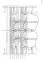
- Fig. 1is a folding structure 1 with double hopper, ie a lying in a plane adjacent the first former 2 and a second former 3, shown.
- the pinch rollers 4 and 5are cut by means not shown, lever mechanisms or directly to a printing material 9 and off. Opposite the pinch rollers 4 and the cutting blades 5 driven over the web width extending tension rollers 6, 8 and a knife roller 7 are arranged (see Fig. 2 ). Alternatively, instead of the draw rolls 6, 8, driven pull rolls positioned opposite the pinch rolls 4 and cutting knives 5 may also be used. Between these, the printing material web 9 is passed, wherein in each case on the front side 10 and on the back 11 of the printing substrate 9 eight pinch rollers 4 are adjustable.
- Each of these eight pressure rollers 4, which are adjustable on the front 10 and the back 11,are mounted axially displaceably by means of a threaded bushing 12 designed, for example, like a lever, on a guide element 13.
- the axial position of the pressure rollers 4is fixed by the threaded bushing 12, in which a threaded spindle 14 can rotate. By rotating this threaded spindle 14, the axial position of the pressure rollers 4 can be adjusted.
- a threaded spindle 14is provided, so that at least two threaded spindles are present.
- the cutting blade 5can be arranged axially displaceably by means of the threaded bushes 12 and adjustable by rotating the threaded spindle 14 in its axial position on the upper guide member 13.
- the cutting blademay also be arranged on a separate threaded spindle, so that the device for axially adjusting the pressure rollers and cutting blades with the above two threaded spindles for the pressure rollers comprises a total of three threaded spindles.
- the bearing on the guide element 13 pinch rollers 4 and 5 cutting bladecan be turned off, for example, to adjust their axial position of the printing substrate 9 and are employed again after the adjustment of its axial position to the printing substrate 9.
- the threaded spindles 14are preferably driven by a drive 23.
- the drive 23drives the threaded spindles 14 either via a gear 24, a Belt drive 25 or a chain drive 26 on.
- a position monitoring device 27, for example, a rotary encoderis arranged on the drive 23, for example, one or more motors.
- the position monitoring device 27can, not shown in detail, also on the gear 24, the belt drive 25 or the chain drive 26 are arranged.
- the position of pinch roller 4 and / or the position of the cutting blade 5depends on the web width of the printing substrate 9 and on the configuration principle of the printing press.
- the threaded spindle 14 for adjusting the pressure rollers 4 and 5 cutting knives according to the configuration principle Idepending on the position of the pressure roller 4 and the position of the cutting blade 5 at certain areas A, B, C, D, E, F a different pitch and / or a different slope direction (see Fig. 4 ).
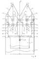
- Fig. 3schematically the configuration principle is shown.
- the formers 2, 3are designed for a maximum web width B max , wherein in a processing of narrower printing material 9 'this is cut before the, not shown, printing units by means of a cutting device 15 in two partial webs 16, 17 and then each the partial webs 16, 17 are guided to the center of the fixed former M F2 , M F3 by means of a, not shown, spreading device and turning devices 18.
- the pressure rollers 4 C , 4 D , 4 E , 4 Fwhich are employed at respective web edges 19 ', 20', 21, 22 of the partial webs 16, 17 must always cover the same, but in different directions, travel X, ie the threaded spindle 14 is configured in the region C, D, E, F with a pitch that is the same in height but different in its direction P (see FIG Fig. 3 and Fig. 4 ).
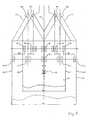
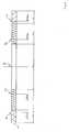
- Fig. 5is shown schematically the configuration principle II.
- the former 2, 3are designed for the minimum web width B min and are at a larger web width to the position 2 '; 3 'pushed apart.
- the position of the pinch rollers 4 G to 4 L and the position of, not shown for clarity, cutting blademust be set to the result of the wider printing material 9 'new format, ie the pinch rollers 4 G , 4 H , 4 I , 4 K. , 4 L and the cutting blades must be set to new non-printing areas.
- the pressure rollers 4 H , 4 I and the cutting blades, which are arranged at the position center hopper M F2 , M F3 and the areas H, I of the threaded spindle 14must be adjusted axially by the first adjustment X, wherein the pressure rollers 4 K , 4 L , which are employed at the respective web edges 19 ', 20' of the wider printing material web 9 ', always have to be adjusted axially by a second adjustment path 2X (see FIG Fig. 5 and Fig. 6 ).
- the second adjustment path 2Xhere corresponds to twice the adjustment path X.
- the threaded spindle 14is in the range K, L for the pressure rollers 4 K , 4 L , which are employed at the respective web edges 19, 20, 19 ', 20', with a compared to the pitch P at the position center of the former M F2 , M F3 , ie in the range H and I, twice as high, but in the same direction extending pitch 2 P designed (see Fig. 5 and Fig. 6 ).
- the threaded spindle 14 for adjusting the pinch roller 4 L in its position 4 ' L at the web edge 20, 20', which is pulled over the former 3, ie in the area L, with a left-common thread with the pitch P.2 configured (see Fig. 5 and Fig. 6 ).
- the threaded rod 14can be constructed in mirror image or symmetrical manner both for the configuration principle I and for the configuration principle II (see FIG Fig. 4 and Fig. 6 ).
- the deviceshould be limited not only to the use of pinch rollers 4 and 5 cutting blades and their arrangement on the double hopper. With the device also Perforier wisdomen, trolleys or skip slitter can be continuously adjusted axially.
- the devicecan also be used for adjusting pressure rollers 4 and / or cutting blades 5 in folder superstructures, turning superstructures and web guiding elements.
- each threaded spindle 14, not shown in detailbe designed with its own drive. Not shown in detail, the cutting blade 5 can be adjusted continuously by a separate common threaded spindle 14 axially.
- the devicemay be configured such that a separate threaded spindle 14 is provided for each adjustment path X, or adjustment path 2X, or adjustment path 3X, wherein the threaded spindles 14 are driven via gearboxes with a defined ratio with respect to rotational speed and direction of rotation.
Landscapes
- Folding Of Thin Sheet-Like Materials, Special Discharging Devices, And Others (AREA)
Description
Translated fromGermanDie Erfindung betrifft eine Vorrichtung zum Verstellen von Andruckrollen oder Schneidmesser an Falzaufbauten oder Wendeaufbauten und Bahnführungselemente gemäß Anspruch 1.The invention relates to a device for adjusting pressure rollers or cutting blades on folding structures or turning structures and web guiding elements according to
Bei Druckmaschinen für variable Bahnbreiten werden entweder die Falztrichter verschoben, oder die Bedruckstoffbahnen werden vor dem Falztrichter in zwei Teilbahnen geschnitten und dann jeweils auf die Mitte der feststehenden Falztrichter mittels Wendeeinrichtungen, beispielsweise Wendestangen, geleitet. In beiden Fällen müssen die Schneidmesser und/oder die Andruckrollen, welche an nicht bedruckte Bereiche der Bedruckstoffbahn angestellt sind, jeweils auf das sich aus der Breite der Bedruckstoffbahn ergebende neue Format eingestellt werden. Beispielsweise bei einer sehr häufig im Falzaufbau realisierten Doppeltrichteranordnung sind dies 16 Andruckrollen und bis zu 3 Schneidmesser, welche auf die verschiedenen Formate verstellt werden müssen, wobei jeweils 8 Andruckrollen auf der Vorderseite und 8 Andruckrollen auf der Rückseite der Bedruckstoffbahn an diese angestellt sind.
Die Verstellung dieser 16 Andruckrollen und 3 Schneidmesser erfolgt heutzutage per Hand oder durch 19 Verstellvorrichtungen mit jeweils einem eigenen Antrieb, d.h. man benötigt zur Verstellung beispielsweise 19 Motoren. Daraus resultiert ein hoher Material- und Verstellaufwand.In printing machines for variable web widths, either the former is shifted, or the printing material are cut before the former into two partial webs and then each directed to the center of the fixed former through turning devices, such as turning bars. In both cases, the cutting blade and / or the pressure rollers, which are employed on non-printed areas of the printing substrate, each to be adjusted to the resulting from the width of the printing material new format. For example, in a double hopper arrangement which is very frequently implemented in the folding structure, these are 16 pressure rollers and up to 3 cutting knives, which have to be adjusted to the various formats, with 8 pressure rollers on the front side and 8 pressure rollers on the back side of the printing material web attached to them.
The adjustment of these 16 pinch rollers and 3 cutting blades is done today by hand or by 19 adjusting devices, each with its own drive, ie you need to adjust, for example, 19 motors. This results in a high material and adjustment costs.
Aus dem Stand der Technik sind folgende Vorrichtungen bekannt.The following devices are known from the prior art.
Die
Die
Die Gewindespindeln 35, 36 enthalten lediglich den Falztrichtern bzw. den Wagen zugeordnete Gewindeabschnitte. Nicht zu verstellenden, von den Gewindespindeln durchgriffenen Organen zugeordnete Zylinderabschnitte sind nicht vorgesehen.The threaded spindles 35, 36 contain only the formers or the car associated threaded sections. Cylinder sections which are not to be adjusted and which are accessed by the threaded spindles are not provided.
Die
Es ist Aufgabe der Erfindung, ein Verfahren zum Verstellen von Andruckrollen und/oder Schneidmesser zu schaffen, welches mit einer geringen Anzahl von Antrieben realisierbar ist.It is an object of the invention to provide a method for adjusting pressure rollers and / or cutting blade, which can be realized with a small number of drives.
Die Aufgabe wird erfindungsgemäß mit den Merkmalen des unabhängigen Patentanspruchs 1 gelöst. Weitere Merkmale und Vorteile ergeben sich aus den Unteransprüchen in Verbindung mit der Beschreibung.The object is achieved with the features of
Die Vorrichtung zum Verstellen der Anpressrollen und/oder Schneidmesser bei Falzaufbauten, insbesondere an der Falztrichterebene, besteht aus gegenüber den Anpressrollen und/oder Schneidmesser angeordnete angetriebene Zugrollen oder über die Bahnbreite sich erstreckende angetriebene Zugwalzen und besteht aus mindestens zwei Gewindespindeln, mittels derer die Anpressrollen und/oder die Schneidmesser axial verstellt werden, wobei beim axialen Verstellen ein Teil der Anpressrollen und/oder Schneidmesser stehen bleibt, ein Teil der Anpressrollen und/oder Schneidmesser einen ersten Verstellweg verstellt werden und/oder ein Teil der Anpressrollen und/oder Schneidmesser einen zweiten Verstellweg verstellt werden.The device for adjusting the pressure rollers and / or cutting blade in Falzaufbauten, especially at the Falztrichterebene, consists of opposite the pressure rollers and / or cutting blade arranged driven tension rollers or over the web width extending driven tension rollers and consists of at least two threaded spindles, by means of which the pressure rollers and / or the cutting blades are axially displaced, wherein during the axial adjustment a part of the pressure rollers and / or cutting blades stops, a part of the pressure rollers and / or cutting blades are adjusted a first adjustment and / or a part of the pressure rollers and / or cutting blade a second adjustment be adjusted.
Vorteil ist, dass eine Verstellung aller Andruckrollen und/oder Schneidmesser in einem Arbeitsschritt erfolgen kann, d.h. es ist eine gleichzeitige oder unmittelbar hintereinander durchführbare Verstellung aller Andruckrollen und/oder Schneidmesser möglich.The advantage is that an adjustment of all pinch rollers and / or cutting blades can be done in one step, i. it is a simultaneous or immediately after each other feasible adjustment of all pinch rollers and / or cutting knife possible.
Dazu ist es notwendig alle Andruckrollen und/oder Schneidmesser axial verschiebbar anzuordnen und die axiale Lage durch eine Gewindebüchse, in der die jeweilige Gewindespindel sich drehen kann zu fixieren, bzw. durch Verdrehen dieser Gewindespindel die axiale Lage zu verstellen. Dies ich machbar, wenn die gemeinsame Gewindespindel, je nach Abhängigkeit der Position von Andruckrolle bzw. der Position vom Schneidmesser an bestimmten Bereichen eine unterschiedliche Steigung und/oder eine unterschiedliche Steigungsrichtung aufweist.For this purpose, it is necessary to arrange all pinch rollers and / or cutting blade axially displaceable and to fix the axial position by a threaded bushing in which the respective threaded spindle can rotate, or to adjust the axial position by turning this threaded spindle. This I feasible if the common threaded spindle, depending on the position of the pressure roller or the position of the cutting blade has a different pitch and / or a different pitch direction at certain areas.
Die Position von Andruckrolle und/oder die Position vom Schneidmesser hängt von der Bahnbreite und vom Konfigurationsprinzip der Druckmaschine ab. Entweder sind die Falztrichter für die maximale Bahnbreite ausgelegt und die schmäleren Bahnen werden jeweils auf die Mitte der feststehenden Falztrichter mittels Wendeeinrichtungen geleitet, oder die Falztrichter werden für die minimale Bahnbreite ausgelegt und werden bei einer größeren Bahnbreite auseinander geschoben. Daraus resultiert die in der
Zur Reduzierung der Rüstzeit können mit solch einer Vorrichtung, mit nur einem Verstellmotor und mit nur einer Positionsüberwachungseinrichtung alle Andruckrollen und/oder Schneidmesser einer Zuggruppe vor dem Falztrichter gleichzeitig oder unmittelbar hintereinander verstellt und in ihrer Position überwacht werden. Zudem ermöglicht dies eine formatunabhängige Bauweise dieser Zuggruppe.To reduce set-up time, all pinch rollers and / or cutting knives of a pulling group can be adjusted in front of the former simultaneously or directly behind one another and monitored in their position with such a device, with only one adjusting motor and with only one position monitoring device. In addition, this allows a format-independent design of this train group.
Im Einzelnen wird die Erfindung anhand eines Ausführungsbeispieles beschrieben.In detail, the invention will be described with reference to an embodiment.
Die Erfindung soll nachfolgend näher anhand der Zeichnungen erläutert werden. In den zugehörigen Figuren zeigt schematisch, die
- Fig. 1
- eine erfindungsgemäße Vorrichtung zum Verstellen von Andruckrollen und/oder Schneidmesser vor einem Falztrichter,
- Fig. 2
- Seitenansicht der Vorrichtung gemäß
Fig. 1 , - Fig. 3
- Falztrichteranordnung einer Druckanlage nach Konfigurationsprinzip I,
- Fig. 4
- Ausgestaltung der Gewindespindel für Konfigurationsprinzip I,
- Fig. 5
- Falztrichteranordnung einer Druckanlage nach Konfigurationsprinzip II,
- Fig. 6
- Ausgestaltung der Gewindespindel für Konfigurationsprinzip II.
- Fig. 1
- a device according to the invention for adjusting pressure rollers and / or cutting blades in front of a former,
- Fig. 2
- Side view of the device according to
Fig. 1 . - Fig. 3
- Forming hopper arrangement of a printing system according to configuration principle I,
- Fig. 4
- Configuration of the threaded spindle for configuration principle I,
- Fig. 5
- Forming hopper arrangement of a printing system according to configuration principle II,
- Fig. 6
- Configuration of the threaded spindle for configuration principle II.
In
Oberhalb der beiden Trichter 2, 3 sind zwischen Seitenwänden 28, 29 gelagert sechzehn Andruckrollen 4 und drei Schneidmesser 5 angeordnet, wobei die Andruckrollen 4 und Schneidmesser 5 mittels, nicht näher dargestellter, Hebelmechanismen oder direkt an eine Bedruckstoffbahn 9 an- und abstellbar sind. Gegenüber den Andruckrollen 4 und den Schneidmessern 5 sind angetriebene über die Bahnbreite sich erstreckende Zugwalzen 6, 8 und eine Messerwalze 7 angeordnet (siehe
Diese jeweils acht Andruckrollen 4, welche an der Vorderseite 10 und der Rückseite 11 anstellbar sind, sind axial verschiebbar mittels einer beispielsweise hebelartig ausgestalteten Gewindebüchse 12 an einem Führungselement 13 gelagert. Die axiale Lage der Andruckrollen 4 ist durch die Gewindebüchse 12, in der eine Gewindespindel 14 sich drehen kann fixiert. Durch Verdrehen dieser Gewindespindel 14 kann die axiale Lage der Andruckrollen 4 verstellt werden. Für die Andruckrollen 4 jeweils einer Seite 10; 11 der Bedruckstoffbahn 9 ist eine Gewindespindel 14 vorgesehen, so dass mindestens zwei Gewindespindeln vorhanden sind.
Zusätzlich können am oberen Führungselement 13 auch die Schneidmesser 5 mittels der Gewindebüchsen 12 axial verschiebbar angeordnet und durch Verdrehen der Gewindespindel 14 in ihrer axialen Lage verstellbar sein.Above the two
Each of these eight
In addition, the cutting blade 5 can be arranged axially displaceably by means of the threaded
Alternativ können, nicht näher dargestellt, die Schneidmesser auch an einer eigenen Gewindespindel angeordnet sein, so dass die Vorrichtung zum axialen Verstellen der Anpressrollen und Schneidmesser mit den oben genannten beiden Gewindespindeln für die Anpressrollen insgesamt drei Gewindespindeln umfaßt.Alternatively, not shown in detail, the cutting blade may also be arranged on a separate threaded spindle, so that the device for axially adjusting the pressure rollers and cutting blades with the above two threaded spindles for the pressure rollers comprises a total of three threaded spindles.
Die am Führungselement 13 gelagerten Andruckrollen 4 und Schneidmesser 5 können beispielsweise zur Verstellung ihrer axialen Lage von der Bedruckstoffbahn 9 abgestellt werden und nach der Verstellung ihrer axialen Lage wieder an die Bedruckstoffbahn 9 angestellt werden.
Die Gewindespindeln 14 sind vorzugsweise von einem Antrieb 23 angetrieben. Der Antrieb 23 treibt die Gewindespindeln 14 entweder über ein Getriebe 24, einen Riementrieb 25 oder einen Kettentrieb 26 an. An dem Antrieb 23, beispielsweise ein oder mehrere Motoren, ist eine Positionüberwachungseinrichtung 27, beispielsweise ein Drehgeber, angeordnet. Die Positionüberwachungseinrichtung 27 kann, nicht näher dargestellt, auch am Getriebe 24, am Riementrieb 25 oder am Kettentrieb 26 angeordnet werden.
Somit ist es möglich mit nur einem Antrieb 23 und nur einer Positionsüberwachungseinrichtung 27 die Verstellung aller Andruckrollen 4 und/oder Schneidmesser 5 zu bewerkstelligen und die axiale Verstellbewegung und/oder axiale Position aller Andruckrollen 4 und/oder Schneidmesser 5 zu überwachen und/oder zu ermitteln. Als Antrieb 23 können auch Schrittmotoren verwendet werden, wobei dadurch der Einsatz von Positionsüberwachungseinrichtungen 27 entfallen kann.The bearing on the
The threaded
Thus, it is possible with only one
Die Position von Andruckrolle 4 und/oder die Position vom Schneidmesser 5 hängt von der Bahnbreite der Bedruckstoffbahn 9 und vom Konfigurationsprinzip der Druckmaschine ab.
Die Gewindespindel 14 zur Verstellung der Andruckrollen 4 und Schneidmesser 5 gemäß dem Konfigurationsprinzip I weist, je nach Abhängigkeit der Position von Andruckrolle 4 bzw. der Position vom Schneidmesser 5 an bestimmten Bereichen A, B, C, D, E, F eine unterschiedliche Steigung und/oder eine unterschiedliche Steigungsrichtung auf (siehe
Die Gewindespindel 14 zur Verstellung der Andruckrollen 4 und Schneidmesser 5 gemäß dem Konfigurationsprinzip II weist, je nach Abhängigkeit der Position von Andruckrolle 4 bzw. der Position vom Schneidmesser 5 an bestimmten Bereichen G, H, I, K, L eine unterschiedliche Steigung und/oder eine unterschiedliche Steigungsrichtung auf (siehe
The threaded
The threaded
In
Die Position der in
Beim Konfigurationsprinzip I müssen die Andruckrollen 4A1, 4A2, 4B1, 4B2 und die, zur besseren Übersicht nicht dargestellten, Schneidmesser, welche in Position Mitte Falztrichter MF2, MF3 angeordnet sind, d.h. dem Bereich A, B der Gewindespindel 14 zugeordnet sind (siehe
Somit bleibt die jeweilige Position der Andruckrolle 4'A1, 4'A2, 4'B1, 4'B2 gegenüber ihrer jeweiligen Position 4A1, 4A2, 4B1, 4B2 unverändert.
Die Andruckrollen 4C, 4D, 4E, 4F, welche an jeweiligen Bahnkanten 19', 20', 21, 22 der Teilbahnen 16, 17 angestellt sind müssen immer den gleichen, jedoch in unterschiedliche Richtung verlaufenden, Verstellweg X zurücklegen, d.h. die Gewindespindel 14 ist im Bereich C, D, E, F mit einer in der Höhe gleichen, aber in ihrer Richtung unterschiedlichen Steigung P ausgestaltet (siehe
In the configuration principle I, the
Thus, the respective position of the
The
Im konkreten Ausführungsbeispiel ist die Gewindespindel 14 zur Verstellung der Andruckrolle 4C in ihre Position 4'C an der Bahnkante 20, 20' , welche über den Falztrichter 3 gezogen wird, d.h. im Bereich C, mit einem rechts-gängigen Gewinde mit der Steigung P=1 ausgestaltet (siehe
Die Gewindespindel 14 ist zur Verstellung der Andruckrolle 4D in ihre Position 4'D am Falztrichter 3 ausgehend Position Mitte Maschine MM, d.h. im Bereich D, mit einem links-gängigen Gewinde mit der Steigung P=1 ausgestaltet (siehe
Die Gewindespindel 14 ist zur Verstellung der Andruckrolle 4E in ihre Position 4'E am Falztrichter 2 ausgehend Position Mitte Maschine MM, d.h. im Bereich E, mit einem rechts-gängigen Gewinde mit der Steigung P=1 ausgestaltet (siehe
The threaded
The threaded
In
Die Andruckrollen 4H, 4I und die Schneidmesser, welche an der Position Mitte Falztrichter MF2, MF3 angeordnet und den Bereichen H, I der Gewindespindel 14 zugeordnet sind, müssen um den ersten Verstellweg X axial verstellt werden, wobei die Andruckrollen 4K, 4L, welche an den jeweiligen Bahnkanten 19', 20' der breiteren Bedruckstoffbahn 9' angestellt sind, immer um einen zweiten Verstellweg 2X axial verstellt werden müssen (siehe
Der zweite Verstellweg 2X entspricht hier dem doppelten Verstellweg X.The
The
Die Gewindespindel 14 ist im Bereich K, L für die Andruckrollen 4K, 4L, welche an den jeweiligen Bahnkanten 19, 20, 19', 20' angestellt sind, mit einer im Vergleich zur Steigung P an der Position Mitte Falztrichter MF2, MF3, d.h. im Bereich H und I, doppelt so hohen, jedoch in gleicher Richtung sich erstreckenden Steigung 2 P ausgestaltet (siehe
Im konkreten Ausführungsbeispiel ist die Gewindespindel 14 zur Verstellung der Andruckrolle 4L in ihre Position 4'L an der Bahnkante 20, 20', welche über den Falztrichter 3 gezogen wird, d.h im Bereich L, mit einem links-gängigen Gewinde mit der Steigung P=2 ausgestaltet (siehe
Die Gewindespindel 14 ist zur Verstellung der Andruckrolle 4I in ihre Position 4'I an der Mitte Falztrichter MF3, d.h. im Bereich I, mit einem links-gängigen Gewinde mit der Steigung P=1 ausgestaltet (siehe
Die Gewindespindel 14 ist zur Verstellung der Andruckrolle 4K in ihre Position 4'K an der Bahnkante 19, 19', welche über den Falztrichter 2 gezogen wird, d.h. im Bereich K, mit einem rechts-gängigen Gewinde mit der Steigung P=2 ausgestaltet (siehe
Die Gewindespindel 14 ist zur Verstellung der Andruckrolle 4H in ihre Position 4'H an der Mitte Falztrichter MF2, d.h. im Bereich H, mit einem rechts-gängigen Gewinde mit der Steigung P= 1 ausgestaltet (siehe
The threaded
Ausgehend von der Position Mitte Maschine MM kann die Gewindestange 14 sowohl für das Konfigurationsprinzip I, als auch für das Konfigurationsprinzip II spiegelbildlich bzw. symmetrisch aufgebaut sein (siehe
Die Vorrichtung soll sich nicht nur auf den Einsatz bei Andruckrollen 4 und Schneidmessern 5 und deren Anordnung am Doppeltrichter beschränken. Mit der Vorrichtung können auch Perforiereinrichtungen, Trolleys oder Skip-Slitter stufenlos axial verstellt werden.
Die Vorrichtung kann auch zum Verstellen von Anpressrollen 4 und/oder Schneidmesser 5 bei Falzaufbauten, Wendeaufbauten und Bahnführungselemente verwendet werden.
Auch kann jede Gewindespindel 14, nicht näher dargestellt, mit ihrem eigenen Antrieb ausgestaltet sein. Nicht näher dargestellt können auch die Schneidmesser 5 von einer eigenen gemeinsamen Gewindespindel 14 stufenlos axial verstellt werden.The device should be limited not only to the use of
The device can also be used for adjusting
Also, each threaded
Die Vorrichtung kann derart ausgestaltet sein, dass für jeden Verstellweg X, oder Verstellweg 2X, oder Verstellweg 3X eine separate Gewindespindel 14 vorgesehen ist, wobei die Gewindespindeln 14 über Getriebe mit definierter Übersetzung bezüglich Drehzahl und Drehrichtung angetrieben werden.The device may be configured such that a separate threaded
- 11
- Falzaufbaufolding structure
- 22
- Falztrichter SIFormer SI
- 33
- Falztrichter SIIForming former SII
- 4,4'4,4 '
- Andruckrollepinch
- 55
- Schneidmessercutting blade
- 66
- Zugwalzepulling roller
- 77
- Messerwalzeknife roll
- 88th
- Zugwalzepulling roller
- 99
- Bedruckstoffbahnprinting material
- 1010
- Vorderseitefront
- 1111
- Rückseiteback
- 1212
- GewindbüchseGewindbüchse
- 1313
- Führungselementguide element
- 1414
- Gewindespindelscrew
- 1515
- Schneidvorrichtungcutter
- 1616
- Teilbahnpart web
- 1717
- Teilbahnpart web
- 1818
- Wendeeinrichtungturning device
- 19, 19'19, 19 '
- Bahnkanteweb edge
- 20, 20'20, 20 '
- Bahnkanteweb edge
- 2121
- Bahnkanteweb edge
- 2222
- Bahnkanteweb edge
- 2323
- Antriebdrive
- 2424
- Getriebetransmission
- 2525
- Riementriebbelt drive
- 2626
- Kettentriebchain drive
- 2727
- PositionüberwachungseinrichtungPosition monitoring device
- 2828
- Seitenwand SISidewall SI
- 2929
- Seitenwand SIISide wall SII
- AA
- Bereich AArea A
- BB
- Bereich BArea B
- CC
- Bereich CArea C
- DD
- Bereich DArea D
- Ee
- Bereich EArea E
- FF
- Bereich FArea F
- GG
- Bereich GArea G
- HH
- Bereich HArea H
- II
- Bereich IArea I
- KK
- Bereich KArea K
- LL
- Bereich LArea L
- MF2MF2
- Mitte Falztrichter 2Middle former 2
- MF3MF3
- Mitte Falztrichter 3Middle former 3
- MMMM
- Mitte MaschineMiddle machine
- BmaxBmax
- Maximale BahnbreiteMaximum web width
- BminBmin
- Minimale BahnbreiteMinimum web width
- XX
- Erster VerstellwegFirst adjustment path
- 2 X2 X
- Zweiter VerstellwegSecond adjustment path
- PP
- Steigungpitch
- P=0P = 0
- Kein Gewinde (P=0)No thread (P = 0)
- P=1P = 1
- Gewinde mit der Steigung P=1Thread with pitch P = 1
- P=2P = 2
- Gewinde mit der Steigung P=2Thread with the pitch P = 2
- 2 P2 p
- Gewinde mit doppelt hoher SteigungThread with double high pitch
- lili
- Links-gängiges GewindeLeft-handed thread
- rere
- Rechts-gängiges GewindeRight-handed thread
Claims (9)
- A device for adjusting pressure rollers (4) or cutting knives (5) in folding superstructures (1) or turning superstructures a web leading elements for processing substrate webs (9, 9') with variable web width (Bmin, Bmax), which can be thrown on on one or on both sides (10, 11) of the substrate web (9, 9') and are arranged in front of the former (2, 3), wherein opposite the pressure rollers (4) or cutting knives (5) driven nips or nipping rollers and knife rollers (6, 7, 8) extending over the web width are arranged, by means of at least one or multiple threaded spindles (14) the pressure rollers (4) or the cutting knives (5) are axially adjustable simultaneously or directly one after the other, wherein during the axial adjusting a part of the pressure rollers (4) or cutting knives (5) remains stationary, a part of the pressure rollers (4) or cutting knives (5) are adjusted a first adjusting travel (X) and a part of the pressure rollers (4) or cutting knives (5) are adjusted a second adjusting travel (2X),characterized in that the threaded spindle (14) is divided into regions (A to F; G to L), each region (A to F; G to L) is assigned individual pressure rollers (4) or cutting knives (5) and the regions (A to F; G to L) are configured with pitches (P) of different pitch height and/or pitch directions, wherein the adjusting travel (X, 2X, 3X) of the individual pressure roller (4) or of the cutting knife (5) the pitch height and/or pitch direction is configured accordingly.
- The device according to claim 1,characterized in that up to three threaded spindles are provided, wherein the pressure rollers (4) in each case are axially adjustable by means of one or two threaded spindles (14) and the cutting knives (5) are axially adjustable by means of one threaded spindle (14).
- The device according to claim 1 or 2,characterized in that for each adjusting travel (X, 2X, 3X) a separate threaded spindle (14) is provided, wherein the threaded spindles (14) are driven via a gearbox with defined transmission ratio with regard to rotational speed and direction of rotation.
- The device according to claim 3,characterized in that starting out from the position middle machine (MM) the threaded rod (14) is constructed symmetrically or in mirror image in the direction of its ends.
- The device according to any one of the preceding claims 1 to 4,characterized in that one or multiple threaded spindles (14) can be drive by at least one drive (23).
- The device according to any one of the preceding claims 1 to 5,characterized in that the axial position of all nips (4) and/or of all cutting knives (5) can be checked and/or determined by at least one position monitoring device (27).
- The device according to any one of the claims 5 or 6,characterized in that the drive (23) is a stepping motor.
- The device according to any one of the preceding claims,characterized in that with a folding device having two stationary formers (2, 3) which are laterally offset against one another and adjusted to the greatest processable web width, in which each web running over a former is assigned at least one set of pressure rollers (4) with pressure rollers (4) assigned to the edges of the web and the middle region of the web, wherein the pressure rollers (4) assigned to the edges of the web are assigned same threaded sections (C, D, E, F) and the pressure rollers (4) assigned to the middle region of the web are assigned thread-free sections (A, B) of the respective assigned threaded spindle (14).
- The device according to any one of the preceding claims 1 to 8,characterized in that in a folding device having two formers (2, 3) which can be adjusted laterally against one another, in which each web running over a former is assigned at least one set of pressure rollers (4) with pressure rollers assigned to the edges of the web and the middle region of the web, wherein the pressure rollers (4) assigned to the web edges facing one another of the two sets are assigned thread-free sections (G) and the remaining pressure rollers (4) are assigned sections (K, H, I, L) provided with a thread of the threaded spindle (14), and wherein the threaded sections (K, L) of the threaded spindle (14) assigned to the pressure rollers (4) which are assigned to the web edges facing away from one another have a pitch that is twice as large as that of the threaded sections (H, I) of the associated threaded spindle (14) assigned to the pressure rollers (4) assigned to the middle regions of the web.
Applications Claiming Priority (2)
| Application Number | Priority Date | Filing Date | Title |
|---|---|---|---|
| DE10250433 | 2002-10-30 | ||
| DE10250433ADE10250433B4 (en) | 2002-10-30 | 2002-10-30 | Device for adjusting pressure rollers and / or cutting blades on folders |
Publications (2)
| Publication Number | Publication Date |
|---|---|
| EP1415944A1 EP1415944A1 (en) | 2004-05-06 |
| EP1415944B1true EP1415944B1 (en) | 2014-12-03 |
Family
ID=32087279
Family Applications (1)
| Application Number | Title | Priority Date | Filing Date |
|---|---|---|---|
| EP03024684.7AExpired - LifetimeEP1415944B1 (en) | 2002-10-30 | 2003-10-28 | Apparatus for the adjustment of pressing rollers and/or cutting blades in folding machines |
Country Status (3)
| Country | Link |
|---|---|
| US (1) | US6949062B2 (en) |
| EP (1) | EP1415944B1 (en) |
| DE (2) | DE10250433B4 (en) |
Families Citing this family (14)
| Publication number | Priority date | Publication date | Assignee | Title |
|---|---|---|---|---|
| DE10313774B4 (en) | 2002-12-18 | 2006-12-14 | Koenig & Bauer Ag | Device for processing a moving material web |
| DE102005010948B4 (en)* | 2005-03-10 | 2007-10-18 | Koenig & Bauer Aktiengesellschaft | Device for separating a printed paper web |
| DE102005042439A1 (en)* | 2005-09-07 | 2007-03-08 | Man Roland Druckmaschinen Ag | Transporting device for web material has pressure rollers on setting unit with at least one piston subject to pressure |
| DE102005042345A1 (en)* | 2005-09-07 | 2007-03-08 | Man Roland Druckmaschinen Ag | Falzwerkoberteil |
| DE102005062843B3 (en)* | 2005-12-27 | 2007-04-19 | Maschinenbau Oppenweiler Binder Gmbh & Co. Kg | Device for folding paper sheets comprises a sheet conveyor and a folding sword with a series of folding rollers arranged one after another in the machine direction |
| DE102007019864B4 (en)* | 2007-04-23 | 2011-06-22 | KOENIG & BAUER Aktiengesellschaft, 97080 | Longitudinal perforating devices for a web-fed rotary printing machine with at least one perforating blade |
| DE102007041811A1 (en)* | 2007-09-03 | 2009-03-05 | Böwe Systec AG | Apparatus and method for conveying a paper web |
| DE102008000057B4 (en)* | 2008-01-15 | 2010-09-23 | Koenig & Bauer Aktiengesellschaft | draw roller assembly |
| DE102008000060B4 (en)* | 2008-01-15 | 2010-09-23 | Koenig & Bauer Aktiengesellschaft | draw roller assembly |
| DE102008044251A1 (en)* | 2008-12-02 | 2010-06-10 | Manroland Ag | former arrangement |
| DE102013113421A1 (en) | 2013-12-04 | 2015-06-11 | Manroland Web Systems Gmbh | Längsschnittmessernachführung |
| CN108908463B (en)* | 2018-06-19 | 2020-07-14 | 嘉兴市康立德构件股份有限公司 | Pinch roller adjusting structure on vulcanized fiber paper cutting device |
| CN109795158B (en)* | 2019-03-13 | 2020-09-18 | 杭州富彩包装制品有限公司 | Manufacturing equipment of self-adaptive packing box |
| CN111776802A (en)* | 2020-08-26 | 2020-10-16 | 界首市鑫华装璜彩印有限公司 | Wrapping paper processing is with unreeling device with axial skew is spacing |
Family Cites Families (14)
| Publication number | Priority date | Publication date | Assignee | Title |
|---|---|---|---|---|
| DE668877C (en)* | 1938-12-10 | Fallert & Co A G | Adjustable double former for rotary printing machines | |
| US3774491A (en)* | 1971-06-28 | 1973-11-27 | Armstrong Cork Co | Universal trimming facility |
| US3896712A (en)* | 1973-12-20 | 1975-07-29 | Winkler Duennebier Kg Masch | Apparatus for machines for the automatic production of postal envelopes |
| US4036115A (en)* | 1974-08-08 | 1977-07-19 | St. Regis-Aci Pty. Limited | Sack making equipment |
| CA1180428A (en)* | 1980-11-13 | 1985-01-02 | Masateru Tokuno | Method and apparatus for positioning tools |
| US4790168A (en)* | 1985-09-09 | 1988-12-13 | Vonthien Gregory W | Pipe crimping and cutting |
| DE4037130A1 (en)* | 1990-04-26 | 1991-11-07 | Roland Man Druckmasch | DEVICE FOR ADJUSTING THE FOLDING FLAPS ON A FOLDING FLAP CYLINDER |
| JP2616832B2 (en)* | 1990-05-16 | 1997-06-04 | 富士写真フイルム株式会社 | Bag making equipment |
| DE4204254C2 (en)* | 1992-02-13 | 1995-03-16 | Koenig & Bauer Ag | Device for longitudinal folding of several paper webs of the same width in a web-fed rotary printing press |
| DE4236347C2 (en)* | 1992-10-28 | 1996-04-04 | Gueldenring Maschinenbau Gmbh | Rip cutter |
| US5790168A (en)* | 1994-07-22 | 1998-08-04 | Hitachi Koki Company, Ltd. | Printing apparatus with movable slitter for printed paper sheet |
| US6358192B1 (en)* | 1997-04-21 | 2002-03-19 | Koenig & Bauer Aktiengesellschaft | Device for adjusting folding jaws |
| DE19830978C2 (en)* | 1998-07-10 | 2000-08-31 | Roland Man Druckmasch | Method for cutting a printing material web in the longitudinal direction and cutting device for cutting the printing material web |
| JP3056484B1 (en)* | 1999-05-21 | 2000-06-26 | 株式会社東京機械製作所 | Outside diameter adjustment device for folding cylinder |
- 2002
- 2002-10-30DEDE10250433Apatent/DE10250433B4/ennot_activeWithdrawn - After Issue
- 2002-10-30DEDE20221976Upatent/DE20221976U1/ennot_activeExpired - Lifetime
- 2003
- 2003-10-28EPEP03024684.7Apatent/EP1415944B1/ennot_activeExpired - Lifetime
- 2003-10-29USUS10/696,009patent/US6949062B2/ennot_activeExpired - Fee Related
Also Published As
| Publication number | Publication date |
|---|---|
| US20040159251A1 (en) | 2004-08-19 |
| DE20221976U1 (en) | 2009-11-26 |
| DE10250433B4 (en) | 2010-05-20 |
| EP1415944A1 (en) | 2004-05-06 |
| US6949062B2 (en) | 2005-09-27 |
| DE10250433A1 (en) | 2004-05-19 |
Similar Documents
| Publication | Publication Date | Title |
|---|---|---|
| DE4204254C2 (en) | Device for longitudinal folding of several paper webs of the same width in a web-fed rotary printing press | |
| EP1742796B1 (en) | Web-fed rotary presses comprising a modifiable folding assembly | |
| EP0257390B1 (en) | Folding apparatus | |
| EP1072551B1 (en) | Folding method and folding apparatus arrangement in a rotary newspaper printing press | |
| DE3637110C1 (en) | Device for cutting and dividing a continuous flow of printed products | |
| EP1415944B1 (en) | Apparatus for the adjustment of pressing rollers and/or cutting blades in folding machines | |
| EP0481172B1 (en) | Rotary printing machine for book and calendar printing, with two longitudinal folding devices | |
| WO2004056686A1 (en) | Devices for treating and/or conveying a strip of material and method for regulating said devices | |
| DE69222147T2 (en) | High precision cutter for strip material | |
| WO2001070609A1 (en) | Device for deflecting a material web | |
| DE4230938C2 (en) | Device for in-line perforation of continuous material webs | |
| EP1762527A2 (en) | Upper part of a folding unit | |
| DE10236658B4 (en) | Cut register allocation | |
| WO2005105445A1 (en) | Printing forms of a printing press, and web-fed rotary presses | |
| EP1742793B1 (en) | Offset printing group pertaining to a printing machine for printing newspapers | |
| WO2003055777A1 (en) | Device for producing folded products | |
| DE20321326U1 (en) | Web-fed printing machine has printer unit printing width of six axially adjacent pages, with superstructure, at least one roller and folder and two printing towers | |
| EP2223806A1 (en) | Device and method for spreading ribbons moving transversely to the machines longitudinal axis in a rotary printing press | |
| DE102018116946A1 (en) | folding device | |
| DE10229457A1 (en) | Pull roller with adjustable pull ring | |
| EP1908588A2 (en) | Rotary printing machine with a printing unit having a plate cylinder | |
| DE9417127U1 (en) | Equipment for processing material | |
| WO1999037568A1 (en) | Web guide | |
| DE20023010U1 (en) | Device for cross cutting a web |
Legal Events
| Date | Code | Title | Description |
|---|---|---|---|
| PUAI | Public reference made under article 153(3) epc to a published international application that has entered the european phase | Free format text:ORIGINAL CODE: 0009012 | |
| AK | Designated contracting states | Kind code of ref document:A1 Designated state(s):AT BE BG CH CY CZ DE DK EE ES FI FR GB GR HU IE IT LI LU MC NL PT RO SE SI SK TR | |
| AX | Request for extension of the european patent | Extension state:AL LT LV MK | |
| 17P | Request for examination filed | Effective date:20040512 | |
| AKX | Designation fees paid | Designated state(s):CH DE FR GB LI | |
| RBV | Designated contracting states (corrected) | Designated state(s):CH DE FR GB LI | |
| 17Q | First examination report despatched | Effective date:20070126 | |
| RAP1 | Party data changed (applicant data changed or rights of an application transferred) | Owner name:MANROLAND AG | |
| 19U | Interruption of proceedings before grant | Effective date:20120201 | |
| 19W | Proceedings resumed before grant after interruption of proceedings | Effective date:20140303 | |
| RAP1 | Party data changed (applicant data changed or rights of an application transferred) | Owner name:MANROLAND WEB SYSTEMS GMBH | |
| GRAP | Despatch of communication of intention to grant a patent | Free format text:ORIGINAL CODE: EPIDOSNIGR1 | |
| INTG | Intention to grant announced | Effective date:20140714 | |
| GRAS | Grant fee paid | Free format text:ORIGINAL CODE: EPIDOSNIGR3 | |
| GRAA | (expected) grant | Free format text:ORIGINAL CODE: 0009210 | |
| AK | Designated contracting states | Kind code of ref document:B1 Designated state(s):CH DE FR GB LI | |
| REG | Reference to a national code | Ref country code:GB Ref legal event code:FG4D Free format text:NOT ENGLISH | |
| REG | Reference to a national code | Ref country code:CH Ref legal event code:NV Representative=s name:E. BLUM AND CO. AG PATENT- UND MARKENANWAELTE , CH Ref country code:CH Ref legal event code:EP | |
| REG | Reference to a national code | Ref country code:DE Ref legal event code:R096 Ref document number:50315174 Country of ref document:DE Effective date:20150115 | |
| REG | Reference to a national code | Ref country code:DE Ref legal event code:R097 Ref document number:50315174 Country of ref document:DE | |
| PLBE | No opposition filed within time limit | Free format text:ORIGINAL CODE: 0009261 | |
| STAA | Information on the status of an ep patent application or granted ep patent | Free format text:STATUS: NO OPPOSITION FILED WITHIN TIME LIMIT | |
| REG | Reference to a national code | Ref country code:FR Ref legal event code:PLFP Year of fee payment:13 | |
| 26N | No opposition filed | Effective date:20150904 | |
| GBPC | Gb: european patent ceased through non-payment of renewal fee | Effective date:20151028 | |
| PG25 | Lapsed in a contracting state [announced via postgrant information from national office to epo] | Ref country code:GB Free format text:LAPSE BECAUSE OF NON-PAYMENT OF DUE FEES Effective date:20151028 | |
| REG | Reference to a national code | Ref country code:FR Ref legal event code:PLFP Year of fee payment:14 | |
| REG | Reference to a national code | Ref country code:FR Ref legal event code:PLFP Year of fee payment:15 | |
| PGFP | Annual fee paid to national office [announced via postgrant information from national office to epo] | Ref country code:DE Payment date:20171019 Year of fee payment:15 Ref country code:FR Payment date:20171024 Year of fee payment:15 | |
| PGFP | Annual fee paid to national office [announced via postgrant information from national office to epo] | Ref country code:CH Payment date:20171019 Year of fee payment:15 | |
| REG | Reference to a national code | Ref country code:DE Ref legal event code:R119 Ref document number:50315174 Country of ref document:DE | |
| REG | Reference to a national code | Ref country code:CH Ref legal event code:PL | |
| PG25 | Lapsed in a contracting state [announced via postgrant information from national office to epo] | Ref country code:DE Free format text:LAPSE BECAUSE OF NON-PAYMENT OF DUE FEES Effective date:20190501 | |
| PG25 | Lapsed in a contracting state [announced via postgrant information from national office to epo] | Ref country code:LI Free format text:LAPSE BECAUSE OF NON-PAYMENT OF DUE FEES Effective date:20181031 Ref country code:CH Free format text:LAPSE BECAUSE OF NON-PAYMENT OF DUE FEES Effective date:20181031 Ref country code:FR Free format text:LAPSE BECAUSE OF NON-PAYMENT OF DUE FEES Effective date:20181031 |