EP1405610B1 - Appliance for orthodontic correction - Google Patents
Appliance for orthodontic correctionDownload PDFInfo
- Publication number
- EP1405610B1 EP1405610B1EP03256245AEP03256245AEP1405610B1EP 1405610 B1EP1405610 B1EP 1405610B1EP 03256245 AEP03256245 AEP 03256245AEP 03256245 AEP03256245 AEP 03256245AEP 1405610 B1EP1405610 B1EP 1405610B1
- Authority
- EP
- European Patent Office
- Prior art keywords
- prong
- teeth
- misaligned teeth
- tooth
- forces
- Prior art date
- Legal status (The legal status is an assumption and is not a legal conclusion. Google has not performed a legal analysis and makes no representation as to the accuracy of the status listed.)
- Expired - Lifetime
Links
- 238000012937correctionMethods0.000titleclaimsdescription10
- 239000000463materialSubstances0.000claimsdescription13
- 238000000034methodMethods0.000claimsdescription9
- 230000014759maintenance of locationEffects0.000claimsdescription4
- 210000002455dental archAnatomy0.000claimsdescription2
- 210000003739neckAnatomy0.000claims5
- 239000000126substanceSubstances0.000claims2
- 238000003780insertionMethods0.000claims1
- 230000037431insertionEffects0.000claims1
- 206010061307Neck deformityDiseases0.000description3
- 238000005452bendingMethods0.000description3
- 210000003484anatomyAnatomy0.000description2
- 238000011282treatmentMethods0.000description2
- 208000012661DyskinesiaDiseases0.000description1
- 206010061274MalocclusionDiseases0.000description1
- 230000004913activationEffects0.000description1
- 239000002537cosmeticSubstances0.000description1
- 210000004513dentitionAnatomy0.000description1
- 230000008030eliminationEffects0.000description1
- 238000003379elimination reactionMethods0.000description1
- 238000001125extrusionMethods0.000description1
- 238000009432framingMethods0.000description1
- 238000009434installationMethods0.000description1
- 238000004519manufacturing processMethods0.000description1
- 239000002184metalSubstances0.000description1
- 230000017311musculoskeletal movement, spinal reflex actionEffects0.000description1
- 238000000926separation methodMethods0.000description1
- 238000006467substitution reactionMethods0.000description1
- 230000036346tooth eruptionEffects0.000description1
- 239000013598vectorSubstances0.000description1
- 230000002747voluntary effectEffects0.000description1
Images


Classifications
- A—HUMAN NECESSITIES
- A61—MEDICAL OR VETERINARY SCIENCE; HYGIENE
- A61C—DENTISTRY; APPARATUS OR METHODS FOR ORAL OR DENTAL HYGIENE
- A61C7/00—Orthodontics, i.e. obtaining or maintaining the desired position of teeth, e.g. by straightening, evening, regulating, separating, or by correcting malocclusions
- A61C7/12—Brackets; Arch wires; Combinations thereof; Accessories therefor
- A61C7/14—Brackets; Fixing brackets to teeth
- A61C7/145—Lingual brackets
- A—HUMAN NECESSITIES
- A61—MEDICAL OR VETERINARY SCIENCE; HYGIENE
- A61C—DENTISTRY; APPARATUS OR METHODS FOR ORAL OR DENTAL HYGIENE
- A61C7/00—Orthodontics, i.e. obtaining or maintaining the desired position of teeth, e.g. by straightening, evening, regulating, separating, or by correcting malocclusions
- A61C7/12—Brackets; Arch wires; Combinations thereof; Accessories therefor
- A61C7/14—Brackets; Fixing brackets to teeth
- A61C7/146—Positioning or placement of brackets; Tools therefor
- A—HUMAN NECESSITIES
- A61—MEDICAL OR VETERINARY SCIENCE; HYGIENE
- A61C—DENTISTRY; APPARATUS OR METHODS FOR ORAL OR DENTAL HYGIENE
- A61C7/00—Orthodontics, i.e. obtaining or maintaining the desired position of teeth, e.g. by straightening, evening, regulating, separating, or by correcting malocclusions
- A61C7/12—Brackets; Arch wires; Combinations thereof; Accessories therefor
- A61C7/20—Arch wires
- A61C7/22—Tension adjusting means
- A—HUMAN NECESSITIES
- A61—MEDICAL OR VETERINARY SCIENCE; HYGIENE
- A61C—DENTISTRY; APPARATUS OR METHODS FOR ORAL OR DENTAL HYGIENE
- A61C7/00—Orthodontics, i.e. obtaining or maintaining the desired position of teeth, e.g. by straightening, evening, regulating, separating, or by correcting malocclusions
- A61C7/002—Orthodontic computer assisted systems
Definitions
- the present inventionrelates to orthodontic correction and in particular to a computer programmed system for orthodontic correction of malocclusions utilizing snap-on features.
- Tooth alignment problemsare corrected by applying appropriate bends to a generally U shaped arch wire if necessary.
- Desired teethare tied to portions of the arch wire, which serve to define proper orientation to them.
- the modes of tooth movement required for misalignments correctionare: up-down (extrusion or intrusion); in-out (both movements towards the tongue and towards the cheek side of the mouth); rotation (turning of the tooth in its socket clockwise or counterclockwise); angulation (tilting of the tooth mesially or distally); torque (twisting of the tooth towards the tongue or cheek side of the mouth); and side-to side tooth movement (lateral).
- Each bracketis provided with a slot for holding the arch wire and top and bottom grooves and tie wings for holding tie wires, the latter being used for binding the brackets to the arch wire.
- the bracketswere first welded to metal bands; the latter were then slipped over individual teeth and cemented in place.
- One-piece orthodontic bracketsare cast or molded to exert a fixed ("average") amount of up down, in out, angulation, rotation, and torque force. This is done to reduce the extent of manual manipulation of the arch wires. It assumes that the brackets will be placed and bonded in an accurately predetermined position.
- a newer method to eliminate wire bending in orthodontic practicehas been disclosed.
- a series of miniature tooth positioners made with the aid of a computeris in present use. This moves teeth in small increments and requires 22 hours per day of voluntary use.
- the theory of this series of positionersis based on the natural anatomy of the teeth, i.e. undercuts of the dentition. The method is slow, relatively inefficient, non-retentive and very limited in its usage.
- US 6,190,166describes an orthodontic device including a wire member and a fixing member.
- the wire memberconsists of an arch wire fixed through concatenation with a tooth and an engaging part fixed at positions corresponding to the points of fixation of the arch wire.
- the fixing member 2 fixed on the toothis provided with a mounting groove for mounting the engaging part.
- US2002/0006597describes a system and method by which an orthodontic appliance is automatically designed and manufactured from digital lower jaw and tooth shape data of a patient provides for preferably scanning a model of the patient's mouth to produce two or three dimensional images and digitizing contours and selected points:
- a computermay be programmed to construct archforms and/or to calculate finish positions of the teeth, then to design an appliance to move the teeth to the calculated positions.
- the appliancemay include archwires and brackets.
- Machine codeis generated and appliances are automatically produced that will straighten the teeth of the patient.
- Custom placement jigsmay also be automatically designed and fabricated and are provided with the custom appliance to position the appliance on the patient's teeth.
- the present inventionutilizes a new methodology to achieve and control involuntary movement for 24 hours a day.
- a separate attachment to each tooth on the lingual or labial sidegreatly amplifies the mechanical force applied to that tooth.
- Each deviceconsists of a bonded base, a short neck and "prong" head, square, triangular or multisided. These devices are a computer-manufactured form for each tooth based on models and impressions previously made.
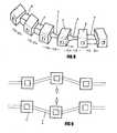
- a second part of the inventionis comprised of a semi-flexible, compartmentalized, U shape arch (also fabricated with computer assistance) which carries a series of connected hollow compartments spaced along the arch so as to be in close proximity to its intended prong head.
- each compartmentis capable of exerting on each tooth-carrying prong head: in-out, up-down, angulation, rotation, torque and side-to-side forces.
- partial orthodontic movementis achieved. It is a relatively simple procedure to replace the first arch with the next sequentially programmed one. This then continues tooth movement by the next increment. When the pre-prepared series of arches has been utilized, the orthodontic procedure is completed. Because the prong head device exerts a much higher leverage on each tooth than the previously described tooth positioners do, the present invention will be more efficient, capable of handling complex cases and able to produce detailed and specific tooth movement. This will result in lower cost and increased patient satisfaction.
- the present inventionmakes use of a basic, repeating prong head unit to transmit corrective forces to misaligned teeth.
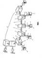
- This unitshown in Fig. 1 is made up of a base 1 having a generally curved contacting surface, which permits the unit to be firmly bonded on the lingual side of the teeth.
- the rest of the unitconsists of the short neck 2 and the prong head 3.
- the prong headswill generally be multisided in shape to which corrective forces are applied to achieve one or more of the desired tooth movements: up down, angulation, rotation, in out, torque, and side to side.
- the prong basesare initially attached to a positioning template 7 as shown in Figs. 2 and 3 .
- the occlusal edges of the basesare initially attached to the template, which serves as a guide for the positioning and bonding of each base to its designated tooth.
- the template 7is broken off at its attachment point to the bonded base and discarded.
- the templatehas been designed and produced by a computerized manufacturing process based on specific prong placement on the desired teeth.
- the bonded prong heads( Fig. 4 ) are ready for activation.
- a thin interproximal, semi flexible, U-shaped arch 12( Fig.5 ) is next prepared. Compartments are positioned on the arch tube at points corresponding to desired selected tooth sites. This is again a computer-assisted operation. Each compartment is provided with flexible entry lips 10, which permit each compartment to engage and retain a prong head. When all the compartments are occupied, one or more of the following forces are exerted on each engaged prong head: up-down, angulation, rotation, in-out, torque and side-to-side movement, achieving in each case a small increment of the desired orthodontic correction. After a suitable period of wearing the arch, it is unsnapped and replaced with a second, sequential arch, which contains computer-installed changes for achieving a second increment of tooth movement.
- the interproximal spaces 6can be semi- flexible or rigid material and be varied in thickness, shape and type of material to aid the desired force generation.
- the interproximal materialcan be compressible ( Fig. 7 ) which forces the hollow compartments apart or extensible material ( Fig. 8 ), which stretches to pull the compartments together.
- Advantages of the present inventioninclude the elimination of orthodontic wires; ligations and other time-consuming appliances now required in orthodontics while achieving complex corrections of high precision.
- Another feature of the present inventionis its ability of moving teeth without patient cooperation.
- the installation of the invention on the lingual side of the toothmakes for low visibility and comfort.
- the inventioncan be use on the labial side of the tooth when cosmetic concerns are not important.
Landscapes
- Health & Medical Sciences (AREA)
- Oral & Maxillofacial Surgery (AREA)
- Dentistry (AREA)
- Epidemiology (AREA)
- Life Sciences & Earth Sciences (AREA)
- Animal Behavior & Ethology (AREA)
- General Health & Medical Sciences (AREA)
- Public Health (AREA)
- Veterinary Medicine (AREA)
- Dental Tools And Instruments Or Auxiliary Dental Instruments (AREA)
Description
- The present invention relates to orthodontic correction and in particular to a computer programmed system for orthodontic correction of malocclusions utilizing snap-on features.
- Wire bending in classic orthodontic practice is a time consuming but essential component of the treatment procedure. Tooth alignment problems are corrected by applying appropriate bends to a generally U shaped arch wire if necessary. When out of line teeth are attached to this wire by means of orthodontic brackets whose wire receiving slots are used as attachment points, forces arise which result in a desired reorientation of the teeth over a period of time. Desired teeth are tied to portions of the arch wire, which serve to define proper orientation to them.
- The modes of tooth movement required for misalignments correction are: up-down (extrusion or intrusion); in-out (both movements towards the tongue and towards the cheek side of the mouth); rotation (turning of the tooth in its socket clockwise or counterclockwise); angulation (tilting of the tooth mesially or distally); torque (twisting of the tooth towards the tongue or cheek side of the mouth); and side-to side tooth movement (lateral).
- Present day orthodontic brackets are applied to the teeth by cementing. Each bracket is provided with a slot for holding the arch wire and top and bottom grooves and tie wings for holding tie wires, the latter being used for binding the brackets to the arch wire. In older techniques, the brackets were first welded to metal bands; the latter were then slipped over individual teeth and cemented in place.
- One-piece orthodontic brackets are cast or molded to exert a fixed ("average") amount of up down, in out, angulation, rotation, and torque force. This is done to reduce the extent of manual manipulation of the arch wires. It assumes that the brackets will be placed and bonded in an accurately predetermined position.
- Since provision has been made for "average" teeth in these fixed systems, there is no allowance for normally occurring differences in dental anatomy or bracket placement errors. Arch wire bending is required to correct the fine alignment problems. Time consuming, expensive iteration is therefore also required.
- A newer method to eliminate wire bending in orthodontic practice has been disclosed. A series of miniature tooth positioners made with the aid of a computer is in present use. This moves teeth in small increments and requires 22 hours per day of voluntary use. The theory of this series of positioners is based on the natural anatomy of the teeth, i.e. undercuts of the dentition. The method is slow, relatively inefficient, non-retentive and very limited in its usage.
US 6,190,166 describes an orthodontic device including a wire member and a fixing member. The wire member consists of an arch wire fixed through concatenation with a tooth and an engaging part fixed at positions corresponding to the points of fixation of the arch wire. Thefixing member 2 fixed on the tooth is provided with a mounting groove for mounting the engaging part.US2002/0006597 describes a system and method by which an orthodontic appliance is automatically designed and manufactured from digital lower jaw and tooth shape data of a patient provides for preferably scanning a model of the patient's mouth to produce two or three dimensional images and digitizing contours and selected points: A computer may be programmed to construct archforms and/or to calculate finish positions of the teeth, then to design an appliance to move the teeth to the calculated positions. The appliance may include archwires and brackets. Machine code is generated and appliances are automatically produced that will straighten the teeth of the patient. Custom placement jigs may also be automatically designed and fabricated and are provided with the custom appliance to position the appliance on the patient's teeth.- The present invention utilizes a new methodology to achieve and control involuntary movement for 24 hours a day. A separate attachment to each tooth on the lingual or labial side greatly amplifies the mechanical force applied to that tooth. Each device consists of a bonded base, a short neck and "prong" head, square, triangular or multisided. These devices are a computer-manufactured form for each tooth based on models and impressions previously made. A second part of the invention is comprised of a semi-flexible, compartmentalized, U shape arch (also fabricated with computer assistance) which carries a series of connected hollow compartments spaced along the arch so as to be in close proximity to its intended prong head. Depending on its orientation and position along the semi-flexible U shaped arch, each compartment is capable of exerting on each tooth-carrying prong head: in-out, up-down, angulation, rotation, torque and side-to-side forces.
- After the patient has worn the initial arch for a period of time, partial orthodontic movement is achieved. It is a relatively simple procedure to replace the first arch with the next sequentially programmed one. This then continues tooth movement by the next increment. When the pre-prepared series of arches has been utilized, the orthodontic procedure is completed. Because the prong head device exerts a much higher leverage on each tooth than the previously described tooth positioners do, the present invention will be more efficient, capable of handling complex cases and able to produce detailed and specific tooth movement. This will result in lower cost and increased patient satisfaction.
Fig. 1 shows side views of the repeating basic prong unit for the upper and lower teeth. Shown are the base of the unit, the short neck and the prong head by which each tooth is gripped and used to exert various corrective forces.Fig 2 is a plan view of a prong-positioning template used to place the corrective prong units in their most suitable points on the lingual side of the teeth, which need correcting.Fig. 3 is a partial isometric view of the prong-positioning template for a section of teeth showing the basic units in place for bonding to the lingual surfaces of said teeth. Also shown are the perforations between the prong heads and the template.Fig. 4 is a plan view of the cemented- in- place prong units each with its base, neck and prong head, after the positioning template has been separated.Fig. 5 is an isometric view of a semi-flexible U shaped arch with hollow compartments connected to each to other by thin, flexible, interproximal material. Each compartment is provided with four flexible entryway lips, which can be slipped over its corresponding prong head engaging its neck for retention. With all the compartments in place, over said prong heads, corrective forces will be exerted on misaligned teeth. An alternative embodiment employs a single, concentric entryway ring instead of the four lips.Fig. 6 is a plan view of a dental arch with a "beginning" semi-flexible U shaped arch in place. The corrective forces generated by this particular arch are only the first of a sequence of orthodontic treatments continued by sequential computer-designed arches. The removal and substitution of the aches is made relatively simple by the use of the retentive flexible lips framing each compartment opening. The neck of each prong head receives the snap-on and snap-off retentive components.Fig 7 is an isometric view of a second embodiment of the invention similar to that shown inFig. 5 but employing semi rigid interproximal blocks used in "finishing arches-filling in the spaces between the hollow compartments. After the interproximal blocks are compressed, and the prong heads are inserted in their corresponding positions, lateral tooth-separation force vectors are exerted on the teeth.Fig. 8 shows the use of semi rigid interproximal block inserts between compartments, which must be stretched to properly engage the prong heads, thus creating lateral tooth-closing forces, as well as compressive type interproximal blocks, which generate expansive tooth-to-tooth forces.Figs 9 to 14 are schematic views showing how various corrective forces are generated by the present invention to remedy malpositioning.Fig. 9 illustrates up and down motion;Fig. 10 illustrates side-to-side motion;Fig. 11 shows in and out motion andFig. 12 shows angulation.Fig. 13 shows rotation whileFig. 14 indicates outward torque.Fig. 15 indicates inward torque.- The present invention makes use of a basic, repeating prong head unit to transmit corrective forces to misaligned teeth. This unit, shown in
Fig. 1 is made up of abase 1 having a generally curved contacting surface, which permits the unit to be firmly bonded on the lingual side of the teeth. The rest of the unit consists of theshort neck 2 and theprong head 3. The prong heads will generally be multisided in shape to which corrective forces are applied to achieve one or more of the desired tooth movements: up down, angulation, rotation, in out, torque, and side to side. - The prong bases are initially attached to a
positioning template 7 as shown inFigs. 2 and3 . The occlusal edges of the bases are initially attached to the template, which serves as a guide for the positioning and bonding of each base to its designated tooth. After the bonding material has set, thetemplate 7 is broken off at its attachment point to the bonded base and discarded. The template has been designed and produced by a computerized manufacturing process based on specific prong placement on the desired teeth. When the template is removed, the bonded prong heads (Fig. 4 ) are ready for activation. - A thin interproximal, semi flexible, U-shaped arch 12 (
Fig.5 ) is next prepared. Compartments are positioned on the arch tube at points corresponding to desired selected tooth sites. This is again a computer-assisted operation. Each compartment is provided withflexible entry lips 10, which permit each compartment to engage and retain a prong head. When all the compartments are occupied, one or more of the following forces are exerted on each engaged prong head: up-down, angulation, rotation, in-out, torque and side-to-side movement, achieving in each case a small increment of the desired orthodontic correction. After a suitable period of wearing the arch, it is unsnapped and replaced with a second, sequential arch, which contains computer-installed changes for achieving a second increment of tooth movement. - This sequence is repeated until final, satisfactory alignment has been achieved, the orthodontic adjustment has been completed, the last arch is discarded and the prong heads are removed. A final, clear plastic aligner can then be worn for a short time to stabilize the correction and prevent relapse
- The interproximal spaces 6 (
Fig. 5 ) can be semi- flexible or rigid material and be varied in thickness, shape and type of material to aid the desired force generation. The interproximal material can be compressible (Fig. 7 ) which forces the hollow compartments apart or extensible material (Fig. 8 ), which stretches to pull the compartments together. - The operating principle of the invention can also be explained by the use of the schematic drawings of
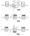
Figs. 9-15 in which the closed end chambers are represented by squares the opening lips by small squares and the interproximal material by horizontal lines. The retention feature can be increased by the use of a circular opening. Fig. 9 represents the generation of up and down forces on a tooth.Fig. 10 shows the generation of side-to-side forces on a tooth.Fig. 11 is a top view of in and out forces.Fig. 12 shows angulation forces.Fig. 13 shows rotation forces.Fig. 14 shows downward twisting torque.Fig 15 shows the generation of upward twisting torque.- Advantages of the present invention include the elimination of orthodontic wires; ligations and other time-consuming appliances now required in orthodontics while achieving complex corrections of high precision. Another feature of the present invention is its ability of moving teeth without patient cooperation. The installation of the invention on the lingual side of the tooth makes for low visibility and comfort. The invention can be use on the labial side of the tooth when cosmetic concerns are not important.
Claims (11)
- A system for correcting misaligned teeth in orthodontics comprising:a. a set of prong units each having a base (1), a neck (2) extending therefrom and terminating in a multi-sided head (3);b. an upper and lower placement template frame (7) which joins each respective prong unit at its base in a computer-oriented pattern and permits each base to firmly and accurately bond to the lingual side of its designated tooth in the upper and lower dental arches and also permits the template frame to be broken free of the now-bonded prong bases and discarded;c. a U shaped arch (12) made up of flexible material with a series of elastic entry compartments (5) closed at one end with four flexible lips (10) at the entry way permitting the insertion and retention of a prong head and its neck which creates a predetermined correction and retention force;whereby, with the arch compartments snapped over their designated prong heads, corrective forces chosen from up-down, in-out, angulation, rotation, torque and side to side can be created on all misaligned teeth, and incremental motion achieved when a series of sequential arches are worn over a period of time with the total correction being attained at the end of the procedure.
- A system for correcting misaligned teeth as claimed in Claim 1 in which said elastic entry compartments (5) are in the shape of hollow chambers closed at one end and provided with elastic lips at their open ends whereby each compartment can be snapped over a multi-sided prong head (3) and adjacent neck (2) to hold it firmly and thus create unique forces which produces a small, incremental tooth movement in a predetermined direction.
- A system for correcting misaligned teeth as claimed in Claim 1 or 2 in which the interproximal material (6) between said entry compartments (5) may be chosen from semi flexible thin substances and semi rigid thick substances as desired.
- A system for correcting misaligned teeth as claimed in any of Claims 1, 2 or 3, in which the interproximal material (6) between said entry compartments (5) may be a variety of contracting and expanding shapes to provide varied correctional forces on the prong heads and their respective computer generated chambers.
- A system for correcting misaligned teeth as claimed in any preceding Claim in which the interproximal material (6) is of flexible material to obtain up-down, in-out, side-to-side, angulation, rotation, torque forces to achieve position corrections of misaligned teeth.
- A system for correcting misaligned teeth as claimed in any preceding Claim in which the prong heads (3) are of multi-sided shape to be inserted and firmly held by said elastic lips (10) in their respective compartment (5) and thus can create leveraged forces on individual teeth.
- A system for correcting misaligned teeth as claimed in any preceding Claim in which said four flexible lips (10) are replaced by a doughnut-shaped, elastic retaining ring for engagement of its prong head (3).
- A system for correcting misaligned teeth as claimed in any preceding Claim in which the prong necks (2) provide leverage for tooth movement and the leverage can be varied by varying the length of the necks.
- A system for correcting misaligned teeth as claimed in any preceding Claim in which the said prongs (1, 2, 3) can be applied to the labial side of the teeth.
- A system for correcting misaligned teeth as claimed in any of the claims 1 to 8 in which the said prongs (1, 2, 3) can be applied to the lingual side of the teeth.
- A system for correcting misaligned teeth as claimed in any preceding claim further comprising bonding material for bonding each prong unit to a selected tooth.
Applications Claiming Priority (2)
| Application Number | Priority Date | Filing Date | Title |
|---|---|---|---|
| US263611 | 2002-10-04 | ||
| US10/263,611US20040067463A1 (en) | 2002-10-04 | 2002-10-04 | Computer programmed system for orthodontic correction of malocclusions utilizing snap-on features |
Publications (3)
| Publication Number | Publication Date |
|---|---|
| EP1405610A2 EP1405610A2 (en) | 2004-04-07 |
| EP1405610A3 EP1405610A3 (en) | 2004-06-09 |
| EP1405610B1true EP1405610B1 (en) | 2008-04-23 |
Family
ID=31993570
Family Applications (1)
| Application Number | Title | Priority Date | Filing Date |
|---|---|---|---|
| EP03256245AExpired - LifetimeEP1405610B1 (en) | 2002-10-04 | 2003-10-03 | Appliance for orthodontic correction |
Country Status (3)
| Country | Link |
|---|---|
| US (2) | US20040067463A1 (en) |
| EP (1) | EP1405610B1 (en) |
| DE (1) | DE60320498T2 (en) |
Cited By (1)
| Publication number | Priority date | Publication date | Assignee | Title |
|---|---|---|---|---|
| WO2017048188A1 (en)* | 2015-09-17 | 2017-03-23 | Wisebrace Pte. Ltd. | 3d printed fixed-removable orthodontic appliance |
Families Citing this family (57)
| Publication number | Priority date | Publication date | Assignee | Title |
|---|---|---|---|---|
| ATE555741T1 (en)* | 2004-03-25 | 2012-05-15 | Dror Ortho Design Ltd | ORTHODONTIC DEVICE |
| DE112009000857T5 (en)* | 2008-04-09 | 2011-05-05 | 3M Innovative Properties Co., Saint Paul | Lingual orthodontic appliance with removable section |
| US8092215B2 (en)* | 2008-05-23 | 2012-01-10 | Align Technology, Inc. | Smile designer |
| CA2740808C (en)* | 2008-11-20 | 2016-04-05 | Align Technology, Inc. | Orthodontic systems and methods including parametric attachments |
| US8356993B1 (en) | 2009-07-06 | 2013-01-22 | Marston Blake E | Orthodontic appliance system |
| FR2950522B1 (en)* | 2009-09-25 | 2012-11-30 | Antoine Meley | ORTHODONTIC WORKING ARC AND ORTHODONTIC TREATMENT SYSTEM COMPRISING THE ARC |
| US20120208144A1 (en)* | 2009-10-02 | 2012-08-16 | Michele Recchia | Orthodontic archwire with integral elements exerting force on the teeth |
| ES2922376T3 (en) | 2010-07-12 | 2022-09-14 | 3Shape As | 3D modeling of an object using textural features |
| IT1402205B1 (en)* | 2010-09-30 | 2013-08-28 | Borri | ORTHODONTIC APPARATUS |
| WO2013134031A1 (en)* | 2012-03-05 | 2013-09-12 | 3M Innovative Properties Company | Flexible orthodontic splint |
| ES2874777T3 (en) | 2012-10-30 | 2021-11-05 | Univ Southern California | Non-slip snap-in archwire orthodontic appliance |
| NZ738712A (en)* | 2013-01-02 | 2019-02-22 | Geniova Tech S L | Removable lingual-vestibular dental alignment device and method for the production thereof |
| US20140255865A1 (en)* | 2013-03-11 | 2014-09-11 | Pawan Gautam | Orthodontic appliance |
| US20140272757A1 (en)* | 2013-03-15 | 2014-09-18 | Zia Chishti | Orthodontic device and method |
| EP2783655A1 (en)* | 2013-03-25 | 2014-10-01 | Image Instruments GmbH | Device and method for positioning brackets |
| NL2011385C2 (en)* | 2013-09-05 | 2015-03-10 | Dentbend Bvba | Orthodontic appliance. |
| US12144703B2 (en) | 2013-12-11 | 2024-11-19 | ArchForm Inc. | Tooth-positioning appliance, systems and methods of producing and using the same |
| US9937018B2 (en)* | 2013-12-11 | 2018-04-10 | Martin G. Martz | Tooth positioning appliance with curved interconnecting elements |
| US10758323B2 (en) | 2014-01-31 | 2020-09-01 | Align Technology, Inc. | Orthodontic appliances with elastics |
| US10555792B2 (en) | 2014-01-31 | 2020-02-11 | Align Technology, Inc. | Direct fabrication of orthodontic appliances with elastics |
| US20170319295A1 (en)* | 2014-02-27 | 2017-11-09 | Richard Bach | Flexible orthodontic device and methods of use |
| CN106413623B (en)* | 2014-03-21 | 2020-07-03 | 阿莱恩技术有限公司 | Segmented orthodontic appliance with elastomer |
| CN116077212A (en) | 2014-06-20 | 2023-05-09 | 阿莱恩技术有限公司 | Elastic piece covered orthodontic appliance |
| CN111631832B (en) | 2014-06-20 | 2022-02-25 | 阿莱恩技术有限公司 | Orthotic with elastic layer |
| US20160095670A1 (en)* | 2014-10-07 | 2016-04-07 | Orametrix, Inc. | Tooth attachment placement device |
| CN107405178A (en)* | 2015-03-13 | 2017-11-28 | 3M创新有限公司 | Orthodontic appliances including arcuate members |
| WO2016183457A1 (en)* | 2015-05-14 | 2016-11-17 | Haralambidis Cosmo | Orthodontic retention components, kit and system |
| US11452578B2 (en) | 2015-05-14 | 2022-09-27 | Cosmo Haralambidis | Orthodontic retention components, kit and system |
| US10314673B2 (en) | 2015-06-01 | 2019-06-11 | Orthodontec Inc. | System for producing a one-piece orthodontic jig and brackets |
| US10028804B2 (en) | 2015-06-01 | 2018-07-24 | Orthodontec Inc. | System for producing a one-piece orthodontic jig and attachments |
| US20170007359A1 (en) | 2015-07-07 | 2017-01-12 | Align Technology, Inc. | Direct fabrication of orthodontic appliances with variable properties |
| WO2017044631A1 (en)* | 2015-09-08 | 2017-03-16 | Martz Martin G | Tooth-positioning appliance, systems and methods of producing and using the same |
| EP3383309B1 (en) | 2015-12-06 | 2023-08-30 | Brius Technologies, Inc. | Teeth repositioning system and method of producing the same |
| US11103330B2 (en)* | 2015-12-09 | 2021-08-31 | Align Technology, Inc. | Dental attachment placement structure |
| US11596502B2 (en)* | 2015-12-09 | 2023-03-07 | Align Technology, Inc. | Dental attachment placement structure |
| AU2016203563B2 (en)* | 2016-05-30 | 2021-07-29 | Andrew S. MARTZ | Tooth positioning appliance with curved interconnecting elements |
| WO2018102588A1 (en) | 2016-12-02 | 2018-06-07 | Swift Health Systems Inc. | Indirect orthodontic bonding systems and methods for bracket placement |
| ES2966191T3 (en) | 2017-01-31 | 2024-04-18 | Swift Health Systems Inc | Hybrid Orthodontic Arch Wires |
| US11612458B1 (en) | 2017-03-31 | 2023-03-28 | Swift Health Systems Inc. | Method of tongue preconditioning in preparation for lingual orthodontic treatment |
| EP4282376A3 (en) | 2017-04-21 | 2024-01-24 | Swift Health Systems Inc. | Indirect bonding tray having several handles |
| US11937991B2 (en) | 2018-03-27 | 2024-03-26 | Align Technology, Inc. | Dental attachment placement structure |
| EP3581143A1 (en)* | 2018-06-12 | 2019-12-18 | 3C | An orthodontic system for the orthodontic treatment of a patient's teeth, a method for the placement of an appliance for the orthodontic treatment of a patient's teeth, and a use of the appliance of such an orthodontic system |
| EP3656342B1 (en)* | 2018-11-26 | 2022-09-21 | Université de Genève | Dental splint |
| EP3930622A4 (en) | 2019-03-01 | 2022-11-16 | Swift Health Systems Inc. | INDIRECT BOND TRAYS WITH BISSTURBO AND ORTHODONTIC AID INTEGRATION |
| MX2021013328A (en)* | 2019-05-02 | 2022-01-24 | Brius Tech Inc | DENTAL DEVICES AND ASSOCIATED MANUFACTURING METHODS. |
| WO2021087158A1 (en) | 2019-10-31 | 2021-05-06 | Swift Health Systems Inc. | Indirect orthodontic bonding systems and methods |
| WO2021130624A1 (en) | 2019-12-27 | 2021-07-01 | 3M Innovative Properties Company | Preformed orthodontic aligner attachments |
| US20210259809A1 (en)* | 2020-02-24 | 2021-08-26 | Align Technology, Inc. | Flexible 3d printed orthodontic device |
| US12090025B2 (en) | 2020-06-11 | 2024-09-17 | Swift Health Systems Inc. | Orthodontic appliance with non-sliding archform |
| US11583378B2 (en)* | 2020-09-03 | 2023-02-21 | Braces On Demand, Inc. | Systems and methods for marking orthodontic devices |
| US12144700B2 (en) | 2020-11-05 | 2024-11-19 | Brius Technologies, Inc. | Dental appliances and associated systems and methods |
| EP4304519A4 (en) | 2021-03-12 | 2025-01-15 | Swift Health Systems Inc. | INDIRECT ORTHODONTIC BONDING SYSTEMS AND METHODS |
| US11504212B2 (en) | 2021-03-25 | 2022-11-22 | Brius Technologies, Inc. | Orthodontic treatment and associated devices, systems, and methods |
| FR3125959B1 (en)* | 2021-08-06 | 2024-05-24 | Valere Frederic | Removable dental appliance |
| EP4395688A4 (en) | 2021-09-03 | 2025-07-02 | Swift Health Systems Inc | Method for administering adhesive for bonding orthodontic brackets |
| WO2023033869A1 (en) | 2021-09-03 | 2023-03-09 | Swift Health Systems Inc. | Orthodontic appliance with non-sliding archform |
| USD1043994S1 (en) | 2022-01-06 | 2024-09-24 | Swift Health Systems Inc. | Archwire |
Family Cites Families (9)
| Publication number | Priority date | Publication date | Assignee | Title |
|---|---|---|---|---|
| US3464114A (en)* | 1967-09-21 | 1969-09-02 | Allen C Brader | Dental attachment with cooperating extension or socket |
| US3896549A (en)* | 1974-04-22 | 1975-07-29 | Melvin Wallshein | Orthodontic elastic band |
| US4856991A (en)* | 1987-05-05 | 1989-08-15 | Great Lakes Orthodontics, Ltd. | Orthodontic finishing positioner and method of construction |
| US5055039A (en)* | 1988-10-06 | 1991-10-08 | Great Lakes Orthodontics, Ltd. | Orthodontic positioner and methods of making and using same |
| DE69327661T2 (en)* | 1992-11-09 | 2000-07-20 | Ormco Corp., Glendora | METHOD AND DEVICE FOR MANUFACTURING INDIVIDUALLY ADAPTED ORTHODONTIC DEVICES |
| NL9400968A (en)* | 1994-06-14 | 1996-01-02 | Aptus Bv | Device for applying a dental device to at least one tooth of at least one row of teeth. |
| JP3059430B1 (en)* | 1999-01-28 | 2000-07-04 | 均 篠倉 | Orthodontic appliance |
| US6554613B1 (en)* | 2000-04-19 | 2003-04-29 | Ora Metrix, Inc. | Method and apparatus for generating an orthodontic template that assists in placement of orthodontic apparatus |
| US6454565B2 (en)* | 2000-04-25 | 2002-09-24 | Align Technology, Inc. | Systems and methods for varying elastic modulus appliances |
- 2002
- 2002-10-04USUS10/263,611patent/US20040067463A1/ennot_activeAbandoned
- 2003
- 2003-10-03DEDE60320498Tpatent/DE60320498T2/ennot_activeExpired - Lifetime
- 2003-10-03EPEP03256245Apatent/EP1405610B1/ennot_activeExpired - Lifetime
- 2005
- 2005-12-12USUS11/299,616patent/US7234934B2/ennot_activeExpired - Fee Related
Cited By (1)
| Publication number | Priority date | Publication date | Assignee | Title |
|---|---|---|---|---|
| WO2017048188A1 (en)* | 2015-09-17 | 2017-03-23 | Wisebrace Pte. Ltd. | 3d printed fixed-removable orthodontic appliance |
Also Published As
| Publication number | Publication date |
|---|---|
| US7234934B2 (en) | 2007-06-26 |
| US20060093984A1 (en) | 2006-05-04 |
| US20040067463A1 (en) | 2004-04-08 |
| DE60320498D1 (en) | 2008-06-05 |
| DE60320498T2 (en) | 2009-05-14 |
| EP1405610A2 (en) | 2004-04-07 |
| EP1405610A3 (en) | 2004-06-09 |
Similar Documents
| Publication | Publication Date | Title |
|---|---|---|
| EP1405610B1 (en) | Appliance for orthodontic correction | |
| US10335253B2 (en) | Tooth-positioning appliance for closing spaces | |
| US9925019B2 (en) | Lingual orthodontic appliance with removable section | |
| US20210369417A1 (en) | Bracket attachment system | |
| EP3072473B1 (en) | Orthodontic appliance with thermoformed aligners | |
| EP3141209B1 (en) | Active attachments for interactions with a polymeric shell dental appliance | |
| EP3581143A1 (en) | An orthodontic system for the orthodontic treatment of a patient's teeth, a method for the placement of an appliance for the orthodontic treatment of a patient's teeth, and a use of the appliance of such an orthodontic system | |
| US20070087302A1 (en) | Orthodontic bracket and method of attaching orthodontic brackets to teeth | |
| WO2007067554A2 (en) | Orthodontic bracket and method of attaching orthodontic brackets to teeth | |
| US8651857B2 (en) | Dental appliance | |
| JP7373665B2 (en) | Custom appliance for bonding orthodontic appliances and method for bonding orthodontic appliances | |
| JP4530636B2 (en) | Computer program system for correcting malocclusions using snap style | |
| EP3267924B1 (en) | Tooth-positioning appliance for closing spaces | |
| CA2575258C (en) | Two phase invisible orthodontics | |
| US20070026358A1 (en) | Two-phase invisible orthodontics | |
| HK1159459A (en) | Orthodontic device |
Legal Events
| Date | Code | Title | Description |
|---|---|---|---|
| PUAI | Public reference made under article 153(3) epc to a published international application that has entered the european phase | Free format text:ORIGINAL CODE: 0009012 | |
| AK | Designated contracting states | Kind code of ref document:A2 Designated state(s):AT BE BG CH CY CZ DE DK EE ES FI FR GB GR HU IE IT LI LU MC NL PT RO SE SI SK TR | |
| AX | Request for extension of the european patent | Extension state:AL LT LV MK | |
| PUAL | Search report despatched | Free format text:ORIGINAL CODE: 0009013 | |
| AK | Designated contracting states | Kind code of ref document:A3 Designated state(s):AT BE BG CH CY CZ DE DK EE ES FI FR GB GR HU IE IT LI LU MC NL PT RO SE SI SK TR | |
| AX | Request for extension of the european patent | Extension state:AL LT LV MK | |
| RIC1 | Information provided on ipc code assigned before grant | Ipc:7A 61C 7/14 B Ipc:7A 61C 7/12 B Ipc:7A 61C 7/00 A | |
| 17P | Request for examination filed | Effective date:20040927 | |
| AKX | Designation fees paid | Designated state(s):DE FR GB | |
| RTI1 | Title (correction) | Free format text:APPLIANCE FOR ORTHODONTIC CORRECTION | |
| GRAP | Despatch of communication of intention to grant a patent | Free format text:ORIGINAL CODE: EPIDOSNIGR1 | |
| GRAS | Grant fee paid | Free format text:ORIGINAL CODE: EPIDOSNIGR3 | |
| GRAA | (expected) grant | Free format text:ORIGINAL CODE: 0009210 | |
| AK | Designated contracting states | Kind code of ref document:B1 Designated state(s):DE FR GB | |
| REG | Reference to a national code | Ref country code:GB Ref legal event code:FG4D | |
| REF | Corresponds to: | Ref document number:60320498 Country of ref document:DE Date of ref document:20080605 Kind code of ref document:P | |
| EN | Fr: translation not filed | ||
| PLBE | No opposition filed within time limit | Free format text:ORIGINAL CODE: 0009261 | |
| STAA | Information on the status of an ep patent application or granted ep patent | Free format text:STATUS: NO OPPOSITION FILED WITHIN TIME LIMIT | |
| 26N | No opposition filed | Effective date:20090126 | |
| PG25 | Lapsed in a contracting state [announced via postgrant information from national office to epo] | Ref country code:FR Free format text:LAPSE BECAUSE OF FAILURE TO SUBMIT A TRANSLATION OF THE DESCRIPTION OR TO PAY THE FEE WITHIN THE PRESCRIBED TIME-LIMIT Effective date:20090227 | |
| REG | Reference to a national code | Ref country code:DE Ref legal event code:R082 Ref document number:60320498 Country of ref document:DE Representative=s name:EINSEL & KOLLEGEN PATENTANWAELTE, DE | |
| REG | Reference to a national code | Ref country code:GB Ref legal event code:732E Free format text:REGISTERED BETWEEN 20121213 AND 20121219 | |
| REG | Reference to a national code | Ref country code:DE Ref legal event code:R081 Ref document number:60320498 Country of ref document:DE Owner name:FAREL A. ROSENBERG LIVING TRUST, BEVERLY HILLS, US Free format text:FORMER OWNER: ROSENBERG, FAREL ARTHUR, BEVERLY HILLS, CALIF., US Effective date:20130102 Ref country code:DE Ref legal event code:R082 Ref document number:60320498 Country of ref document:DE Representative=s name:PATENTANWAELTE EINSEL & KOLLEGEN, DE Effective date:20130102 | |
| PGFP | Annual fee paid to national office [announced via postgrant information from national office to epo] | Ref country code:DE Payment date:20161031 Year of fee payment:14 | |
| PGFP | Annual fee paid to national office [announced via postgrant information from national office to epo] | Ref country code:GB Payment date:20170918 Year of fee payment:15 | |
| REG | Reference to a national code | Ref country code:DE Ref legal event code:R119 Ref document number:60320498 Country of ref document:DE | |
| PG25 | Lapsed in a contracting state [announced via postgrant information from national office to epo] | Ref country code:DE Free format text:LAPSE BECAUSE OF NON-PAYMENT OF DUE FEES Effective date:20180501 | |
| GBPC | Gb: european patent ceased through non-payment of renewal fee | Effective date:20181003 | |
| PG25 | Lapsed in a contracting state [announced via postgrant information from national office to epo] | Ref country code:GB Free format text:LAPSE BECAUSE OF NON-PAYMENT OF DUE FEES Effective date:20181003 |