EP1402639B1 - Non-contact proximity sensor - Google Patents
Non-contact proximity sensorDownload PDFInfo
- Publication number
- EP1402639B1 EP1402639B1EP02732290AEP02732290AEP1402639B1EP 1402639 B1EP1402639 B1EP 1402639B1EP 02732290 AEP02732290 AEP 02732290AEP 02732290 AEP02732290 AEP 02732290AEP 1402639 B1EP1402639 B1EP 1402639B1
- Authority
- EP
- European Patent Office
- Prior art keywords
- sensor
- sensor electrode
- processor
- capacitive
- metal sheet
- Prior art date
- Legal status (The legal status is an assumption and is not a legal conclusion. Google has not performed a legal analysis and makes no representation as to the accuracy of the status listed.)
- Expired - Lifetime
Links
- 239000002184metalSubstances0.000claimsdescription27
- 230000000694effectsEffects0.000claimsdescription7
- 238000004891communicationMethods0.000claimsdescription6
- 239000000758substrateSubstances0.000claimsdescription6
- 230000007613environmental effectEffects0.000claimsdescription5
- 238000012545processingMethods0.000claimsdescription3
- 239000010410layerSubstances0.000description16
- 239000003990capacitorSubstances0.000description11
- 238000012546transferMethods0.000description7
- 230000005684electric fieldEffects0.000description3
- 230000003071parasitic effectEffects0.000description3
- 230000035945sensitivityEffects0.000description3
- 239000012790adhesive layerSubstances0.000description2
- 238000004519manufacturing processMethods0.000description2
- 238000000034methodMethods0.000description2
- 229910000831SteelInorganic materials0.000description1
- 238000007792additionMethods0.000description1
- 230000000740bleeding effectEffects0.000description1
- 239000004020conductorSubstances0.000description1
- 238000012217deletionMethods0.000description1
- 230000037430deletionEffects0.000description1
- 238000001514detection methodMethods0.000description1
- 230000002708enhancing effectEffects0.000description1
- 238000012986modificationMethods0.000description1
- 230000004048modificationEffects0.000description1
- 238000007789sealingMethods0.000description1
- 239000010959steelSubstances0.000description1
Images


Classifications
- H—ELECTRICITY
- H03—ELECTRONIC CIRCUITRY
- H03K—PULSE TECHNIQUE
- H03K17/00—Electronic switching or gating, i.e. not by contact-making and –breaking
- H03K17/94—Electronic switching or gating, i.e. not by contact-making and –breaking characterised by the way in which the control signals are generated
- H03K17/945—Proximity switches
- H03K17/955—Proximity switches using a capacitive detector
- E—FIXED CONSTRUCTIONS
- E05—LOCKS; KEYS; WINDOW OR DOOR FITTINGS; SAFES
- E05F—DEVICES FOR MOVING WINGS INTO OPEN OR CLOSED POSITION; CHECKS FOR WINGS; WING FITTINGS NOT OTHERWISE PROVIDED FOR, CONCERNED WITH THE FUNCTIONING OF THE WING
- E05F15/00—Power-operated mechanisms for wings
- E05F15/40—Safety devices, e.g. detection of obstructions or end positions
- E05F15/42—Detection using safety edges
- E05F15/46—Detection using safety edges responsive to changes in electrical capacitance
- E—FIXED CONSTRUCTIONS
- E05—LOCKS; KEYS; WINDOW OR DOOR FITTINGS; SAFES
- E05Y—INDEXING SCHEME ASSOCIATED WITH SUBCLASSES E05D AND E05F, RELATING TO CONSTRUCTION ELEMENTS, ELECTRIC CONTROL, POWER SUPPLY, POWER SIGNAL OR TRANSMISSION, USER INTERFACES, MOUNTING OR COUPLING, DETAILS, ACCESSORIES, AUXILIARY OPERATIONS NOT OTHERWISE PROVIDED FOR, APPLICATION THEREOF
- E05Y2900/00—Application of doors, windows, wings or fittings thereof
- E05Y2900/50—Application of doors, windows, wings or fittings thereof for vehicles
- E05Y2900/53—Type of wing
- E05Y2900/55—Windows
Definitions
- the present inventionrelates to a non-contact proximity sensor.
- the present inventionrelates to a capacitive sensor for use in controlling movement of a power accessory in an automobile.
- Proximity sensorsare widely used in the automotive industry to automate the control of power accessories. For instance, proximity sensors are often used in power window controllers to detect the presence of obstructions in the window frame when the window pane is being directed to the closed position.
- One proximity sensor commonly used as a power window controllercomprises a voltage sensor coupled between the window actuator and the actuator power source.
- the obstructionincreases the electrical load imposed on the window actuator, thereby causing the load voltage at the window actuator to drop.
- the voltage sensoris configured to sense any drop in load voltage and to command the window actuator to stop or to reverse the direction of movement of the window pane when such a voltage drop is detected.
- Another proximity sensor commonly used as a power window controllercomprises a speed sensor coupled to the window actuator.
- the speed sensoris configured to sense any change in actuator speed and to command the window actuator to stop or to reverse the direction of movement of the window pane when such a change in actuator speed is detected.
- Another proximity sensor employedcomprises a pressure sensitive strip disposed around the upper edge of the window frame.
- the pressure sensitive stripsignals the window actuator to stop further movement of the window pane.
- Peterteaches a solution which uses a capacitive sensor mounted on the weather seal at the top of the window frame.
- the capacitive sensorcomprises a first insulating layer disposed over the window sheet metal, a conductive guard layer disposed over the first insulating layer, a second insulating layer disposed over the guard layer, and a touch plate disposed over the second insulating layer.
- the guard layeris driven by an alternating voltage signal which is identical in amplitude and phase to the voltage imposed on the touch plate.
- Peterallows the window actuator to respond more rapidly to obstructions in the window frame
- Peterrequires that the guard layer be the same size as the touch plate for optimum cancellation of touch plate capacitance.
- the disclosed manufacturing tolerancescan greatly increase the manufacturing cost of the capacitive sensor. Consequently, there remains a need for a proximity sensor which will not allow an obstruction to become pinched between the window pane and the window frame when the window pane is being directed to the closed position.
- the disadvantages of the prior artmay be overcome by providing a capacitive sensor that can be used as a non-contact pinch sensor and a non-contact obstacle sensor.
- a capacitive proximity sensorwhich includes an elongate sensor electrode, a conductive metal sheet extending significantly beyond the sensor electrode, a dielectric disposed between the metal sheet and the sensor electrode, a substrate layer, and a dielectric layer interposed between the substrate layer and the conductive metal sheet and bonded to the substrate and the metal sheet.
- a vehicular power accessory controllerwhich includes an elongate sensor electrode, a capacitive shield extending significantly beyond the sensor electrode, a dielectric disposed between the capacitive shield and the sensor electrode and bonded to the sensor electrode from the capacitive shield, a sensor processor in electrical communication with the sensor electrode for processing sense data received from the sensor electrode, and a power accessory actuator in electrical communication with the sensor processor for effecting movement of the power accessory in accordance with the processed sense data.
- a capacitive proximity sensordenoted generally as 100, comprising a sensor electrode 102, a capacitive shield 104 and a dielectric 106.
- the sensor electrode 102is used to detect the strength of the electric field in proximity to the sensor electrode 102, and comprises a straight elongate electrically-conductive wire.
- the sensor electrode 102has a substantially circular or flat transverse cross-section.
- the suggested shapes for the sensor electrode 102increase the surface area of the sensor electrode 102, thereby enhancing the sensitivity of the proximity sensor 100.
- other conductor shapes and orientationsmay be utilized in accordance with the application of the proximity sensor 100.
- the capacitive shield 104is configured to provide partial capacitive shielding for the sensor electrode 102.
- the capacitive shield 104comprises an electrically-conductive metal sheet 108, an adhesive layer 110, and a dielectric layer 112 interposed between the adhesive layer 110 and the metal sheet 108.
- the metal sheet 108comprises a substantially planar metal sheet and is disposed substantially parallel to the longitudinal axis of the sensor electrode 102. Further, as shown, for proper shielding of the sensor axis of the sensor electrode 102. Further, as shown, for proper shielding of the sensor electrode 102, the area occupied by the metal sheet 108 is substantially greater than that of the sensor electrode 102.
- the dielectric 106is disposed between the capacitive shield 104 and the sensor electrode 102 and electrically isolates the sensor electrode 102 from the capacitive shield 104.
- the dielectric 106encloses the sensor electrode 102, thereby protecting the sensor electrode 102 from external impact.
- the dielectric layer 112 of the capacitive shield 104is integrally formed with the dielectric 106, such that the dielectric 106 and the dielectric layer 112 together form a unitary dielectric body which encloses the sensor electrode 102 and the metal sheet 108.
- the proximity sensor 100also includes a sensor processor 114 disposed within the dielectric layer 112 of the capacitive shield 104.
- the sensor processor 114may also be disposed externally to the proximity sensor 100, if desired.
- the sensor processor 114comprises an Application Specific Integrated Circuit (ASIC), and is in electrical communication with the sensor electrode 102 for processing sense data received from the sensor electrode 102.
- ASICApplication Specific Integrated Circuit
- the sensor processor 114includes an I/O port connected to the proximity sensor 100, a voltage pulse train generator, a first electronic switch connected between the pulse train generator and the I/O port for applying voltage pulses to the proximity sensor 100, an internal storage capacitor, a second electronic switch connected between the storage capacitor and the I/O port for transferring electronic charge from the proximity sensor 100 to the storage capacitor, and a third electronic switch connected between the storage capacitor and ground for bleeding off any parasitic voltage resulting from the charge transfer.
- the sensor processor 114is configured to apply voltage pulse trains from the pulse train generator to the sensor electrode 102 (by closing the first electronic switch), and to transfer the resulting charge from the proximity sensor 100 to the storage capacitor (by closing the second electronic switch) at the end of each pulse train.
- the sensor processor 114is also configured to bleed off parasitic voltage effects resulting from the charge transfer (by momentarily closing the third electronic switch), at the end of each charge transfer.
- the sensor processor 114is able to detect objects in proximity to the proximity sensor 100, while also compensating for capacitive changes arising from environmental conditions (eg. humidity, temperature, dirt over the sensor electrode 102). To do so, the sensor processor 114 is configured to measure the cycle count of the storage capacitor after a predetermined number of charge transfer cycles, and to calculate an average quiescent cycle count value from the measured cycle count values. The sensor processor 114 is also configured to compare the rate of change of measured cycle counts against the rate of change in average quiescent cycle count value. If the measured cycle count exceeds the rate of change in average quiescent cycle count value, the sensor processor 114 assumes that the change in cycle count resulted from the presence of an object in proximity to the proximity sensor 100, rather than a change in environmental conditions.
- environmental conditionseg. humidity, temperature, dirt over the sensor electrode 102
- Fig. 3depicts the proximity sensor 100 implemented as a component of a power accessory controller.
- the proximity sensor 100is secured to an automobile metal body part (eg. disposed within the rubber sealing strip of a window frame or a power sliding door), with the sensor processor 114 being connected to the automobile's power actuator 202 (which controls the movement of the window pane in the window frame or the movement of the sliding door).
- the figuredepicts the intrinsic capacitance Ci associated with the automobile, and the capacitance Co associated with an obstruction, such as a human hand.
- Fig. 4is a schematic representation of a proximity sensor 200 which is a variation of the proximity sensor 100.
- the proximity sensor 200is substantially similar to the proximity sensor 100, and is implemented as a component of a power accessory controller.
- the sensor processor 114 of the proximity sensor 200is in electrical communication with the sensor electrode 102 and the metal sheet 108 and is configured to transmit electrical pulses to the sensor electrode 102 and the metal sheet 108, and to process the resulting sense data received from the sensor electrode 102.
- This variationis advantageous since the electric field produced by the metal sheet 108 (due to the electrical pulses transmitted from the sensor processor 114) reduces the impact the steel body of the automobile body part can have on the shape of the electric field detected by the sensor electrode 102.
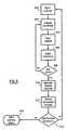
- the sensor processor 114resets a loop counter, removes all charge stored in the internal storage capacitor.
- the sensor processor 114then transmits a train of electrical pulses to the sensor electrode 102 (or both the sensor electrode 102 and the metal sheet 108), at step 302, causing an electrical charge to be transferred to the sensor electrode 102.
- the sensor processor 114transfers the charge stored on the sensor electrode 102 to the internal storage capacitor, at step 304.
- the sensor processor 114bleeds off any parasitic voltage effects resulting from the charge transfer step (ie. step 304).
- the sensor processor 114increments the loop counter, and then determines whether the loop counter has reached a predetermined maximum loop value. If the maximum loop value has not been reached, the sensor processor 114 repeats steps 302 to 306 again. However, if the maximum loop value has been reached, the sensor processor 114 measures the cycle count of the charge stored in the storage capacitor, at step 310.
- the pulse width of each electrical pulse and the number of electrical pulses transferred to the sensor electrode 102 (at step 302), and the maximum loop valueare all selected in accordance with the length and type of the sensor electrode 102 such that the capacitive value of the sensor electrode 102 can be determined from the cycle count of the storage capacitor when the maximum loop value has been reached.
- the sensor processor 114integrates all the sensor cycle count values (measured at step 310) to determine a reference quiescent sensor cycle count. Since the reference cycle count is determined dynamically, the reference cycle count varies in accordance with capacitive drift due to, for example, dirt over the sensor electrode 102.
- the sensor processor 114compares the instantaneous rate of change of the sensor cycle count with the average rate of change of the reference cycle count. If the instantaneous rate of change of the sensor cycle count exceeds the average rate of change of the reference cycle count (eg. due to the presence of a human hand in the window frame), the sensor processor 114 transmits an output control signal to the power actuator 202, at step 316, thereby alerting the power actuator 202 of the obstruction. Otherwise, the sensor processor 114 repeats steps 300 to 312.
- the sensor processor 114If the sensor processor 114 detects an obstruction, the sensor processor 114 operatively effects the power actuator 202 to terminate movement of the accessory. Alternatively, the sensor processor 114 can effect the power actuator 202 to terminate and reverse movement of the accessory.
- the magnitude of the measured cycle countwill vary in accordance with the area occupied by the sensor electrode 102, the magnitude of the gap between the sensor electrode 102 and the automobile body part, and the presence or absence of the obstruction capacitance Co.
- the metal sheet 108 of the capacitive shield 104is electrically isolated from the sensor electrode 102, and the metal sheet 108 is substantially larger in terms of area than the sensor electrode 102, the measured cycle count is not affected appreciably by the intrinsic capacitance Ci associated with the automobile.
- the power actuator 202If the power actuator 202 is directing the window pane of the automobile window frame (or the sliding door) to a closed position, upon receipt of the control signal the power actuator 202 immediately stops movement of the window pane (or sliding door).
- the cycle count measured by the sensor processor 114does not depend appreciably on the intrinsic capacitance Ci associated with the automobile, the presence of a cycle count differential due to the obstruction capacitance Co will be more readily identified than if the measured cycle count was affected by the intrinsic capacitance Ci. Consequently, the requisite output control signal to the power actuator 202 will be produced more rapidly and more reliably than with proximity sensor configurations which lack the capacitive shield 104.
Landscapes
- Measurement Of Length, Angles, Or The Like Using Electric Or Magnetic Means (AREA)
- Power-Operated Mechanisms For Wings (AREA)
- Switches That Are Operated By Magnetic Or Electric Fields (AREA)
- Electronic Switches (AREA)
- Train Traffic Observation, Control, And Security (AREA)
Description
Claims (15)
- A capacitive proximity sensor comprising:characterized by said sensor electrode selectively receiving a voltage pulse train andtransferring a resulting charge.an elongate sensor electrode;a conductive metal sheet extending significantly beyond the sensor electrode andpositioned to provide partial capacitive shielding for the sensor electrode; anda dielectric bonded to and disposed between the metal sheet and the sensorelectrode; anda dielectric layer bonded to the metal sheet, the dielectric and the dielectric layerforming a unitary dielectric body enclosing the sensor electrode and the metal sheet,
- The proximity sensor according to claim 1, wherein the elongate sensor electrodehas a transverse cross-section, the cross-section comprising one of a circular and arectangular cross-section.
- The proximity sensor according to claim 2, wherein the metal sheet issubstantially planar.
- The proximity sensor according to claim 3, wherein dielectric layer has a sensorprocessor disposed within said dielectric layer, said sensor processor configured togenerate said voltage pulse train and to measure a cycle count at the sensor electrode atthe end of each pulse train.
- A power accessory controller for an automobile, comprising:an elongate sensor electrode;a capacitive shield extending significantly beyond the sensor electrode andpositioned to provide partial capacitive shielding for the sensor electrode;a dielectric disposed between the capacitive shield and the sensor electrode andbonded to the sensor electrode from the capacitive shield;a sensor processor in electrical communication with the sensor electrode forselectively applying voltage pulses to the sensor electrode and processing sense datareceived from the sensor electrode; anda power accessory actuator in electrical communication with the sensor processorfor effecting movement of the accessory in accordance with the processed sense data.
- The power accessory controller according to claim 5, wherein the elongate sensorelectrode comprises a wire having a transverse cross-section, the cross-sectioncomprising one of a circular and a rectangular cross-section.
- The power accessory controller according to claim 6, wherein the sensorprocessor is configured to compensate for capacitive changes arising from environmentalconditions.
- The power accessory controller according to claim 7, wherein the sensorprocessor is configured to detect an obstruction when a rate of change of the sense dataexceeds a rate of change of the capacitive compensation.
- The power accessory controller according to claim 8, wherein the sensorprocessor is configured to receive the sense data by applying trains of cycle count pulsesto the sensor electrode, and measuring a cycle count at the sensor electrode at the end ofeach pulse train.
- The power accessory controller according to claim 8, wherein the sensorprocessor is configured to compensate for the environmental conditions by determiningan average quiescent value for the measured cycle count.
- The power accessory controller according to claim 9, wherein the capacitiveshield comprises a conductive metal sheet, a substrate configured for attachment to theautomobile, and a dielectric layer interposed between the substrate and the conductivemetal sheet and bonded to the substrate and the metal sheet.
- The power accessory controller according to claim 10, wherein and the sensorprocessor measures a cycle count at the sensor electrode at the end of each pulse train,and is also configured to compensate for the environmental conditions by determining anaverage quiescent value for the measured cycle count.
- The power accessory controller according to claim 11, wherein the sensorprocessor comprises an application specific integrated circuit disposed within thedielectric layer.
- The power accessory controller according to claim 13, wherein the sensorprocessor after detecting an obstruction, operatively effects said actuator to terminatesaid movement.
- The power accessory controller according to claim 14, wherein the sensorprocessor after effecting said actuator to terminate said movement, operatively effectssaid actuator to effect movement of said accessory in an opposite direction.
Applications Claiming Priority (3)
| Application Number | Priority Date | Filing Date | Title |
|---|---|---|---|
| US29648301P | 2001-06-08 | 2001-06-08 | |
| US296483P | 2001-06-08 | ||
| PCT/CA2002/000880WO2002101929A2 (en) | 2001-06-08 | 2002-06-10 | Non-contact proximity sensor |
Publications (2)
| Publication Number | Publication Date |
|---|---|
| EP1402639A2 EP1402639A2 (en) | 2004-03-31 |
| EP1402639B1true EP1402639B1 (en) | 2004-11-17 |
Family
ID=23142189
Family Applications (1)
| Application Number | Title | Priority Date | Filing Date |
|---|---|---|---|
| EP02732290AExpired - LifetimeEP1402639B1 (en) | 2001-06-08 | 2002-06-10 | Non-contact proximity sensor |
Country Status (6)
| Country | Link |
|---|---|
| US (1) | US6946853B2 (en) |
| EP (1) | EP1402639B1 (en) |
| JP (1) | JP2005501375A (en) |
| CA (1) | CA2451010C (en) |
| DE (1) | DE60201998T2 (en) |
| WO (1) | WO2002101929A2 (en) |
Cited By (2)
| Publication number | Priority date | Publication date | Assignee | Title |
|---|---|---|---|---|
| US8493081B2 (en) | 2009-12-08 | 2013-07-23 | Magna Closures Inc. | Wide activation angle pinch sensor section and sensor hook-on attachment principle |
| US9234979B2 (en) | 2009-12-08 | 2016-01-12 | Magna Closures Inc. | Wide activation angle pinch sensor section |
Families Citing this family (75)
| Publication number | Priority date | Publication date | Assignee | Title |
|---|---|---|---|---|
| US7293467B2 (en)* | 2001-07-09 | 2007-11-13 | Nartron Corporation | Anti-entrapment system |
| US7132642B2 (en)* | 2001-07-09 | 2006-11-07 | Nartron Corporation | Anti-entrapment systems for preventing objects from being entrapped by translating devices |
| US7162928B2 (en)* | 2004-12-06 | 2007-01-16 | Nartron Corporation | Anti-entrapment system |
| GB2401974B (en)* | 2003-05-17 | 2005-11-09 | Smarta Systems Ltd | Electronic safety control system |
| JP4481997B2 (en) | 2003-12-18 | 2010-06-16 | インティアー オートモーティヴ クロージャーズ インコーポレイテッド | Anti-pinch differential capacitance sensor |
| US20060055415A1 (en)* | 2004-09-15 | 2006-03-16 | Mark Takita | Environmentally compensated capacitive sensor |
| US7312591B2 (en) | 2005-03-11 | 2007-12-25 | Npc Corporation | Powered panel moving system |
| US7504833B1 (en) | 2005-04-01 | 2009-03-17 | Cypress Semiconductor Corporation | Automatically balanced sensing device and method for multiple capacitive sensors |
| TW200644422A (en)* | 2005-04-22 | 2006-12-16 | Cypress Semiconductor Corp | Directional capacitive sensor system and method |
| EP1875156A2 (en)* | 2005-04-27 | 2008-01-09 | Roho, Inc. | Proximity sensor |
| DE102005043534B4 (en)* | 2005-09-12 | 2013-07-04 | Webasto Ag | Anti-trap device in the automotive field |
| US20070095595A1 (en)* | 2005-11-02 | 2007-05-03 | Arvinmeritor Light Vehicle Systems-France | Anti-squeeze method utilizing airbag information |
| GB2432913B (en)* | 2005-12-02 | 2010-04-14 | Ford Global Tech Llc | A switching arrangement for a storage receptacle of a motor vehicle |
| US7342373B2 (en)* | 2006-01-04 | 2008-03-11 | Nartron Corporation | Vehicle panel control system |
| US8040142B1 (en) | 2006-03-31 | 2011-10-18 | Cypress Semiconductor Corporation | Touch detection techniques for capacitive touch sense systems |
| US7721609B2 (en) | 2006-03-31 | 2010-05-25 | Cypress Semiconductor Corporation | Method and apparatus for sensing the force with which a button is pressed |
| US8004497B2 (en)* | 2006-05-18 | 2011-08-23 | Cypress Semiconductor Corporation | Two-pin buttons |
| US7688013B2 (en)* | 2006-06-21 | 2010-03-30 | Flextronics Automotive Inc. | System and method for controlling speed of a closure member |
| US7521665B2 (en) | 2006-07-07 | 2009-04-21 | Leoni Ag | Sensor system, sensor element, and method with a light sensor and an electrical sensor for monitoring a closing mechanism |
| US8902173B2 (en)* | 2006-09-29 | 2014-12-02 | Cypress Semiconductor Corporation | Pointing device using capacitance sensor |
| US8547114B2 (en) | 2006-11-14 | 2013-10-01 | Cypress Semiconductor Corporation | Capacitance to code converter with sigma-delta modulator |
| US8058937B2 (en) | 2007-01-30 | 2011-11-15 | Cypress Semiconductor Corporation | Setting a discharge rate and a charge rate of a relaxation oscillator circuit |
| US9500686B1 (en) | 2007-06-29 | 2016-11-22 | Cypress Semiconductor Corporation | Capacitance measurement system and methods |
| US8570053B1 (en) | 2007-07-03 | 2013-10-29 | Cypress Semiconductor Corporation | Capacitive field sensor with sigma-delta modulator |
| US8169238B1 (en) | 2007-07-03 | 2012-05-01 | Cypress Semiconductor Corporation | Capacitance to frequency converter |
| US8525798B2 (en) | 2008-01-28 | 2013-09-03 | Cypress Semiconductor Corporation | Touch sensing |
| US8319505B1 (en) | 2008-10-24 | 2012-11-27 | Cypress Semiconductor Corporation | Methods and circuits for measuring mutual and self capacitance |
| US8358142B2 (en) | 2008-02-27 | 2013-01-22 | Cypress Semiconductor Corporation | Methods and circuits for measuring mutual and self capacitance |
| US9104273B1 (en) | 2008-02-29 | 2015-08-11 | Cypress Semiconductor Corporation | Multi-touch sensing method |
| JP5102716B2 (en)* | 2008-08-08 | 2012-12-19 | 慶一 野々垣 | Capacitive proximity sensor |
| US8321174B1 (en) | 2008-09-26 | 2012-11-27 | Cypress Semiconductor Corporation | System and method to measure capacitance of capacitive sensor array |
| EP2338143A2 (en)* | 2008-10-08 | 2011-06-29 | Johnson Controls Technology Company | Sensor actuated storage compartment |
| DE202009009028U1 (en)* | 2009-07-01 | 2010-12-30 | Brose Fahrzeugteile Gmbh & Co. Kommanditgesellschaft, Hallstadt | Capacitive sensor unit |
| US12141432B2 (en) | 2009-07-02 | 2024-11-12 | Uusi, Llc | Vehicle occupant detection system |
| US11726651B2 (en) | 2009-07-02 | 2023-08-15 | Uusi, Llc | Vehicle occupant detection system |
| US9046967B2 (en)* | 2009-07-02 | 2015-06-02 | Uusi, Llc | Vehicle accessory control interface having capactive touch switches |
| US10592092B2 (en) | 2009-07-02 | 2020-03-17 | Uusi, Llc. | User interface with proximity detection for object tracking |
| US11216174B2 (en) | 2009-07-02 | 2022-01-04 | Uusi, Llc | User interface with proximity detection for object tracking |
| US8723827B2 (en) | 2009-07-28 | 2014-05-13 | Cypress Semiconductor Corporation | Predictive touch surface scanning |
| US10017977B2 (en)* | 2009-08-21 | 2018-07-10 | Uusi, Llc | Keyless entry assembly having capacitance sensor operative for detecting objects |
| US9575481B2 (en)* | 2009-08-21 | 2017-02-21 | Uusi, Llc | Fascia panel assembly having capacitance sensor operative for detecting objects |
| US9845629B2 (en) | 2009-08-21 | 2017-12-19 | Uusi, Llc | Vehicle keyless entry assembly having capacitance sensor operative for detecting objects |
| US9705494B2 (en)* | 2009-08-21 | 2017-07-11 | Uusi, Llc | Vehicle assemblies having fascia panels with capacitance sensors operative for detecting proximal objects |
| US9199608B2 (en)* | 2009-08-21 | 2015-12-01 | Uusi, Llc | Keyless entry assembly having capacitance sensor operative for detecting objects |
| US10954709B2 (en) | 2009-08-21 | 2021-03-23 | Uusi, Llc | Vehicle assembly having a capacitive sensor |
| US9051769B2 (en) | 2009-08-21 | 2015-06-09 | Uusi, Llc | Vehicle assembly having a capacitive sensor |
| US11634937B2 (en)* | 2009-08-21 | 2023-04-25 | Uusi, Llc | Vehicle assembly having a capacitive sensor |
| US12320180B2 (en) | 2009-08-21 | 2025-06-03 | Uusi, Llc | Vehicle assembly having a capacitive sensor |
| FR2949499B1 (en)* | 2009-08-26 | 2011-10-07 | Sarl Baia | ELECTROMAGNETIC SUCTION |
| WO2011038514A1 (en)* | 2009-10-02 | 2011-04-07 | Magna Closures Inc. | Vehicular anti-pinch system with rain compensation |
| US20120074961A1 (en)* | 2010-09-29 | 2012-03-29 | Kopin Corporation | Capacitive sensor with active shield electrode |
| US9384166B2 (en)* | 2011-04-22 | 2016-07-05 | Panasonic Intellectual Property Management Co., Ltd. | Vehicular input device and vehicular input method |
| DE102011112274A1 (en)* | 2011-09-05 | 2013-03-07 | Brose Fahrzeugteile Gmbh & Co. Kg, Hallstadt | control system |
| DE102011121775B3 (en) | 2011-12-21 | 2013-01-31 | Brose Fahrzeugteile Gmbh & Co. Kg, Hallstadt | Control system for controlling e.g. motorized side door of motor car, has distance sensors with dummy portions such that sensors comprise no sensitivity or smaller sensitivity compared to region of each sensor adjacent to dummy portions |
| US10334960B2 (en) | 2012-01-09 | 2019-07-02 | L&P Property Management Company | Drop-in occupancy detection component for furniture |
| US9482707B2 (en) | 2012-01-09 | 2016-11-01 | L&P Property Management Company | Occupancy detection for automated recliner furniture |
| US10197259B2 (en) | 2012-01-09 | 2019-02-05 | L&P Property Management Company | Standalone capacitance sensor for furniture |
| US10048662B2 (en) | 2012-01-09 | 2018-08-14 | L&P Property Management Company | Characterization and calibration for automated furniture |
| US10555615B2 (en) | 2012-01-09 | 2020-02-11 | L&P Property Management Company | Calibration of detection features for automated furniture |
| US10197609B2 (en) | 2012-01-09 | 2019-02-05 | L&P Property Management Company | Capacitive sensing for automated furniture |
| US9337831B2 (en) | 2012-01-09 | 2016-05-10 | L&P Property Management Company | Capacitive wire sensing for furniture |
| DE102012013065A1 (en) | 2012-07-02 | 2014-01-02 | Brose Fahrzeugteile Gmbh & Co. Kg, Hallstadt | Method for controlling a closure element arrangement of a motor vehicle |
| DE102013015119A1 (en)* | 2013-09-12 | 2015-03-12 | Brose Fahrzeugteile Gmbh & Co. Kommanditgesellschaft, Hallstadt | Adjusting device for adjusting a vehicle between an adjustable position and an open position adjustable vehicle part |
| DE102013114881A1 (en) | 2013-12-25 | 2015-06-25 | Brose Fahrzeugteile Gmbh & Co. Kommanditgesellschaft, Hallstadt | Control system for a motor-driven closure element arrangement of a motor vehicle |
| DE102013114883A1 (en) | 2013-12-25 | 2015-06-25 | Brose Fahrzeugteile Gmbh & Co. Kommanditgesellschaft, Hallstadt | Control system for a motor-driven closure element arrangement of a motor vehicle |
| US10444862B2 (en) | 2014-08-22 | 2019-10-15 | Synaptics Incorporated | Low-profile capacitive pointing stick |
| DE102015112589A1 (en) | 2015-07-31 | 2017-02-02 | Brose Fahrzeugteile Gmbh & Co. Kommanditgesellschaft, Bamberg | Control system for a motor-adjustable loading space device of a motor vehicle |
| DE102015119701A1 (en) | 2015-11-15 | 2017-05-18 | Brose Fahrzeugteile Gmbh & Co. Kommanditgesellschaft, Bamberg | Method for operating a capacitive sensor arrangement of a motor vehicle |
| US10078103B2 (en) | 2016-08-26 | 2018-09-18 | Microsoft Technology Licensing, Llc | Fringing field booster |
| US10118542B1 (en) | 2017-05-03 | 2018-11-06 | Ford Global Technologies, Llc | Vehicle side lighting arrangement |
| DE102018107479A1 (en)* | 2017-09-14 | 2019-03-14 | Huf Hülsbeck & Fürst Gmbh & Co. Kg | Arrangement for evaluation in a capacitive sensor device in a vehicle |
| DE102018131856A1 (en)* | 2018-12-12 | 2020-06-18 | Huf Hülsbeck & Fürst Gmbh & Co. Kg | Arrangement for a vehicle |
| CN112946758B (en)* | 2021-01-28 | 2022-06-10 | 中科(湖南)先进轨道交通研究院有限公司 | Non-contact capacitive train proximity sensor and working method thereof |
| USD1073985S1 (en) | 2022-10-18 | 2025-05-06 | Uusi, Llc | Sensor weather seal |
| JP2024176779A (en)* | 2023-06-09 | 2024-12-19 | 東芝テック株式会社 | Detection device and detection program |
Family Cites Families (18)
| Publication number | Priority date | Publication date | Assignee | Title |
|---|---|---|---|---|
| DE3818456A1 (en)* | 1988-05-31 | 1989-12-14 | Kabelmetal Electro Gmbh | SAFETY DEVICE FOR AN AUTOMATICALLY MOVING WINDOW WINDOW OF A MOTOR VEHICLE |
| AT391735B (en)* | 1988-09-01 | 1990-11-26 | Mewald Gmbh | FEELING BAR |
| US5074073A (en)* | 1990-10-17 | 1991-12-24 | Zwebner Ascher Z | Car door safety device |
| US5191268A (en)* | 1991-08-26 | 1993-03-02 | Stanley Home Automation | Continuously monitored supplemental obstruction detector for garage door operator |
| DE4205251A1 (en)* | 1992-02-21 | 1993-08-26 | Hella Kg Hueck & Co | DEVICE FOR MONITORING THE CLOSING PROCESS OF A MOTOR-DRIVEN WINDOW WINDOW, IN PARTICULAR A MOTOR VEHICLE WINDOW WINDOW |
| US5334876A (en)* | 1992-04-22 | 1994-08-02 | Nartron Corporation | Power window or panel controller |
| US5422551A (en)* | 1992-05-23 | 1995-06-06 | Koito Manufacturing Co., Ltd. | Safety device and method for power window |
| US5955854A (en)* | 1992-09-29 | 1999-09-21 | Prospects Corporation | Power driven venting of a vehicle |
| GB2319294B (en)* | 1993-10-18 | 1998-07-08 | Draftex Ind Ltd | Moveable-window safety device |
| US5801340A (en)* | 1995-06-29 | 1998-09-01 | Invotronics Manufacturing | Proximity sensor |
| US5730165A (en)* | 1995-12-26 | 1998-03-24 | Philipp; Harald | Time domain capacitive field detector |
| US6356097B1 (en)* | 1997-06-20 | 2002-03-12 | Applied Materials, Inc. | Capacitive probe for in situ measurement of wafer DC bias voltage |
| JP4245094B2 (en)* | 1998-02-25 | 2009-03-25 | ダウマル カステリョン メルチョール | Obstacle detection system for automatic window glass elevator |
| US6051945A (en)* | 1999-01-25 | 2000-04-18 | Honda Giken Kogyo Kabushiki Kaisha | Anti-pinch safety system for vehicle closure device |
| US6452514B1 (en)* | 1999-01-26 | 2002-09-17 | Harald Philipp | Capacitive sensor and array |
| US6135494A (en)* | 1999-04-21 | 2000-10-24 | Breed Automotive Technology Inc. | Occupant proximity sensor with horn switch |
| JP2003506671A (en) | 1999-07-29 | 2003-02-18 | エービー・オートモティブ・エレクトロニクス・リミテッド | Capacitive sensor |
| AU2001278339A1 (en) | 2000-08-03 | 2002-02-18 | Atoma International Corp. | Vehicle closure anti-pinch assembly having a non-contact sensor |
- 2002
- 2002-06-10WOPCT/CA2002/000880patent/WO2002101929A2/enactiveIP Right Grant
- 2002-06-10CACA2451010Apatent/CA2451010C/ennot_activeExpired - Fee Related
- 2002-06-10JPJP2003504545Apatent/JP2005501375A/enactivePending
- 2002-06-10EPEP02732290Apatent/EP1402639B1/ennot_activeExpired - Lifetime
- 2002-06-10DEDE60201998Tpatent/DE60201998T2/ennot_activeExpired - Lifetime
- 2002-06-10USUS10/480,074patent/US6946853B2/ennot_activeExpired - Fee Related
Cited By (3)
| Publication number | Priority date | Publication date | Assignee | Title |
|---|---|---|---|---|
| US8493081B2 (en) | 2009-12-08 | 2013-07-23 | Magna Closures Inc. | Wide activation angle pinch sensor section and sensor hook-on attachment principle |
| US9234979B2 (en) | 2009-12-08 | 2016-01-12 | Magna Closures Inc. | Wide activation angle pinch sensor section |
| US9417099B2 (en) | 2009-12-08 | 2016-08-16 | Magna Closures Inc. | Wide activation angle pinch sensor section |
Also Published As
| Publication number | Publication date |
|---|---|
| WO2002101929A2 (en) | 2002-12-19 |
| EP1402639A2 (en) | 2004-03-31 |
| DE60201998T2 (en) | 2005-11-24 |
| CA2451010C (en) | 2012-01-03 |
| DE60201998D1 (en) | 2004-12-23 |
| WO2002101929A3 (en) | 2003-03-06 |
| JP2005501375A (en) | 2005-01-13 |
| CA2451010A1 (en) | 2002-12-19 |
| US20040178924A1 (en) | 2004-09-16 |
| US6946853B2 (en) | 2005-09-20 |
Similar Documents
| Publication | Publication Date | Title |
|---|---|---|
| EP1402639B1 (en) | Non-contact proximity sensor | |
| US8334623B2 (en) | Capacitive moisture independent crush protection | |
| US7046129B2 (en) | Device for detecting an obstacle in the opening range of a movable closure element | |
| WO2013091267A1 (en) | Anti-pinch sensor of electric vehicle window and method thereof | |
| US7908927B2 (en) | Anti-entrapment system | |
| US8156826B2 (en) | Anti-pinch sensor | |
| CA2464747A1 (en) | Multizone capacitive anti-pinch system | |
| US20060186900A1 (en) | Detector with capacitance sensor for detecting object being caught by door | |
| US7902841B2 (en) | Capacitive proximity sensor | |
| US20030071727A1 (en) | Non-contact obstacle detection system utilizing ultra sensitive capacitive sensing | |
| JP2715280B2 (en) | Device for interrupting the closing process of electric closing parts in automobiles | |
| WO2014140888A2 (en) | Combination capacitive and resistive obstacle sensor | |
| EP1449225A2 (en) | Flexible capacitive strip for use in a non-contact obstacle detection system | |
| CN105051306A (en) | Anti-pinch guards for adjustable vehicle components | |
| EP1745547B1 (en) | Capacitance activated switch device | |
| JP2007533268A5 (en) | ||
| JP2000346717A5 (en) | ||
| KR101977949B1 (en) | System for an Obstacle Avoidance Using Proximity Sensor of Multi Electrode | |
| JP2001032628A (en) | Device and method for preventing pinching | |
| JP2023551100A (en) | Non-contact pinch prevention device | |
| JP3755209B2 (en) | Powered window opening and closing device for vehicles |
Legal Events
| Date | Code | Title | Description |
|---|---|---|---|
| PUAI | Public reference made under article 153(3) epc to a published international application that has entered the european phase | Free format text:ORIGINAL CODE: 0009012 | |
| 17P | Request for examination filed | Effective date:20031230 | |
| AK | Designated contracting states | Kind code of ref document:A2 Designated state(s):AT BE CH CY DE DK ES FI FR GB GR IE IT LI LU MC NL PT SE TR | |
| AX | Request for extension of the european patent | Extension state:AL LT LV MK RO SI | |
| GRAP | Despatch of communication of intention to grant a patent | Free format text:ORIGINAL CODE: EPIDOSNIGR1 | |
| GRAS | Grant fee paid | Free format text:ORIGINAL CODE: EPIDOSNIGR3 | |
| GRAA | (expected) grant | Free format text:ORIGINAL CODE: 0009210 | |
| AK | Designated contracting states | Kind code of ref document:B1 Designated state(s):DE FR GB IT | |
| RBV | Designated contracting states (corrected) | Designated state(s):DE FR GB IT | |
| REG | Reference to a national code | Ref country code:GB Ref legal event code:FG4D | |
| REG | Reference to a national code | Ref country code:IE Ref legal event code:FG4D | |
| REF | Corresponds to: | Ref document number:60201998 Country of ref document:DE Date of ref document:20041223 Kind code of ref document:P | |
| PLBE | No opposition filed within time limit | Free format text:ORIGINAL CODE: 0009261 | |
| STAA | Information on the status of an ep patent application or granted ep patent | Free format text:STATUS: NO OPPOSITION FILED WITHIN TIME LIMIT | |
| 26N | No opposition filed | Effective date:20050818 | |
| ET | Fr: translation filed | ||
| REG | Reference to a national code | Ref country code:FR Ref legal event code:PLFP Year of fee payment:15 | |
| PGFP | Annual fee paid to national office [announced via postgrant information from national office to epo] | Ref country code:GB Payment date:20160608 Year of fee payment:15 Ref country code:DE Payment date:20160607 Year of fee payment:15 | |
| PGFP | Annual fee paid to national office [announced via postgrant information from national office to epo] | Ref country code:IT Payment date:20160621 Year of fee payment:15 | |
| REG | Reference to a national code | Ref country code:DE Ref legal event code:R082 Ref document number:60201998 Country of ref document:DE Representative=s name:GLAWE DELFS MOLL PARTNERSCHAFT MBB VON PATENT-, DE | |
| REG | Reference to a national code | Ref country code:FR Ref legal event code:PLFP Year of fee payment:16 | |
| PGFP | Annual fee paid to national office [announced via postgrant information from national office to epo] | Ref country code:FR Payment date:20170511 Year of fee payment:16 | |
| REG | Reference to a national code | Ref country code:DE Ref legal event code:R119 Ref document number:60201998 Country of ref document:DE | |
| GBPC | Gb: european patent ceased through non-payment of renewal fee | Effective date:20170610 | |
| PG25 | Lapsed in a contracting state [announced via postgrant information from national office to epo] | Ref country code:DE Free format text:LAPSE BECAUSE OF NON-PAYMENT OF DUE FEES Effective date:20180103 Ref country code:GB Free format text:LAPSE BECAUSE OF NON-PAYMENT OF DUE FEES Effective date:20170610 | |
| PG25 | Lapsed in a contracting state [announced via postgrant information from national office to epo] | Ref country code:IT Free format text:LAPSE BECAUSE OF NON-PAYMENT OF DUE FEES Effective date:20170610 | |
| PG25 | Lapsed in a contracting state [announced via postgrant information from national office to epo] | Ref country code:FR Free format text:LAPSE BECAUSE OF NON-PAYMENT OF DUE FEES Effective date:20180630 |