EP1401048A1 - Antenna installation for a mobile communications base station - Google Patents
Antenna installation for a mobile communications base stationDownload PDFInfo
- Publication number
- EP1401048A1 EP1401048A1EP02020876AEP02020876AEP1401048A1EP 1401048 A1EP1401048 A1EP 1401048A1EP 02020876 AEP02020876 AEP 02020876AEP 02020876 AEP02020876 AEP 02020876AEP 1401048 A1EP1401048 A1EP 1401048A1
- Authority
- EP
- European Patent Office
- Prior art keywords
- mast
- antennas
- antenna system
- radio
- lamp
- Prior art date
- Legal status (The legal status is an assumption and is not a legal conclusion. Google has not performed a legal analysis and makes no representation as to the accuracy of the status listed.)
- Withdrawn
Links
- 238000009434installationMethods0.000titleclaimsdescription4
- 238000010295mobile communicationMethods0.000titledescription4
- 239000011152fibreglassSubstances0.000claimsdescription12
- 230000005611electricityEffects0.000claimsdescription8
- 229910000831SteelInorganic materials0.000claimsdescription7
- 239000010959steelSubstances0.000claimsdescription7
- 239000000463materialSubstances0.000claimsdescription4
- 238000004873anchoringMethods0.000claims1
- 238000004378air conditioningMethods0.000description3
- 238000013461designMethods0.000description3
- 229910001018Cast ironInorganic materials0.000description2
- 238000001816coolingMethods0.000description2
- 238000012545processingMethods0.000description2
- 230000006978adaptationEffects0.000description1
- 239000010426asphaltSubstances0.000description1
- 238000005452bendingMethods0.000description1
- 239000004566building materialSubstances0.000description1
- 238000005253claddingMethods0.000description1
- 238000011161developmentMethods0.000description1
- 230000018109developmental processEffects0.000description1
- 238000005516engineering processMethods0.000description1
- 238000000034methodMethods0.000description1
- 230000003287optical effectEffects0.000description1
- 230000002093peripheral effectEffects0.000description1
- 239000011347resinSubstances0.000description1
- 229920005989resinPolymers0.000description1
- 239000004575stoneSubstances0.000description1
- XLYOFNOQVPJJNP-UHFFFAOYSA-NwaterSubstancesOXLYOFNOQVPJJNP-UHFFFAOYSA-N0.000description1
Images

Classifications
- H—ELECTRICITY
- H01—ELECTRIC ELEMENTS
- H01Q—ANTENNAS, i.e. RADIO AERIALS
- H01Q1/00—Details of, or arrangements associated with, antennas
- H01Q1/44—Details of, or arrangements associated with, antennas using equipment having another main function to serve additionally as an antenna, e.g. means for giving an antenna an aesthetic aspect
- H—ELECTRICITY
- H01—ELECTRIC ELEMENTS
- H01Q—ANTENNAS, i.e. RADIO AERIALS
- H01Q1/00—Details of, or arrangements associated with, antennas
- H01Q1/12—Supports; Mounting means
- H01Q1/1242—Rigid masts specially adapted for supporting an aerial
- H—ELECTRICITY
- H01—ELECTRIC ELEMENTS
- H01Q—ANTENNAS, i.e. RADIO AERIALS
- H01Q1/00—Details of, or arrangements associated with, antennas
- H01Q1/12—Supports; Mounting means
- H01Q1/22—Supports; Mounting means by structural association with other equipment or articles
- H01Q1/24—Supports; Mounting means by structural association with other equipment or articles with receiving set
- H01Q1/241—Supports; Mounting means by structural association with other equipment or articles with receiving set used in mobile communications, e.g. GSM
- H01Q1/246—Supports; Mounting means by structural association with other equipment or articles with receiving set used in mobile communications, e.g. GSM specially adapted for base stations
Definitions
- the inventionrelates to an antenna system of a base station for the Mobile radio for installation in the local area, with antennas, the antennas and a mast at a predetermined height above the ground Circuit complex for feeding the antennas.
- Radio mastsshould ideally be like this be set up so that a nationwide supply is guaranteed.
- GSMGlobal System for Mobile Communication
- BTSBase Transceiver System
- the radius of action of a base stationnamely a sending and receiving station, which is usually abbreviated as "BTS" (Base Transceiver System)
- BTSBase Transceiver System
- UMTSUniversal Mobile Telecommunication System
- the inventionis also intended to provide mobile communications for such Areas.
- the Mastis a street lamp mast that has an outer mast wall at least in some areas and which has at least one lamp for street lighting contains the antennas within the mast outer wall, at least in the area of the antennas from a transparent to the radio signal of the antennas, but opaque material.
- the lamppostswhich are also available in narrow street conditions or at least be tolerated and by stylistic adjustment of the outside, for example in the form of cast iron mast parts, visually to the environment are adaptable, for example, have a height between 10 and 22 m.
- the mobile radio antennascan be seen in the lantern mast volume in the upper area can be installed, which then through the radio-permeable, but optically opaque Outside wall parts are clad.
- the radio-permeable mast outer wallwhich is mostly made of glass fiber reinforced Plastic exists, does not have sufficient load capacity for a mast.
- the Lantern mastis other than its own weight Exposed to loads, especially wind power and possible impact forces.
- the mast in the parts where the mast outer wall is made for the radio signalsare made of permeable material, one inside it its longitudinal direction supporting structure, which consists in particular of a central rod running in the mast. This rod takes over for the length of the antenna area, generally for the top one Partial length of the mast, the carrying function that is usual in the rest of the area the mast outer wall provides.
- the radio-permeable parts of the outer wall of the mastare designed as tubular ducts and are from the central rod running in the pipe channel via radial Holders that have free space between them for laying cables let, held.
- An appropriate height division of the mast lengthcan look so that the Mast, from bottom to top, has the following partial lengths: one only for bridging the height serving part length; a partial antenna length with radio permeable Outer wall and antennas inside; a partial length of light that the at least one lamp, which in turn contains at least one lamp, wearing; and as the upper end a radio link partial length with one in one Directional radio antenna located.
- the lightscan do this they have almost all of the designs used for street lamps can extend around the mast or on this over one or more Boom attached.
- the lamppostnaturally does not offer sufficient space for the in The circuitry known to the experts as "technology", which is responsible for the administration the radio interface, the reservation and release of radio channels, controls paging and signal processing.
- This Circuitryis housed in one or more cabinets, depending on the design and ambient temperature also cooling require.
- the circuit complex in a near the The lamppostis located in the building and the lamppost be connected by cable. If no building is available for this, it is a preferred solution that the circuit complex at least is partially housed in a submerged housing.
- the possible heat emission part of a heat pump cycleis however nevertheless preferably arranged above the surface, for example below an outdoor bench.
- the recessed caseis a quiver for the mast is anchored and divided into two accessible spaces, one of which is the electricity meter and the power supply for the lamps contains and the other, which is lockable from the former room, contains the circuit complex for feeding the antennas, so that on the one hand there is a compact design that meets all requirements, and on the other hand, it is ensured that for reading the electricity meter and not responsible for the power supply of the lamps Have access to the circuit complex for mobile radio.
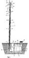
- Fig. 1shows an antenna lantern mast 1 with a lamp 2, the one Lamp 3 contains and serves as a street lamp, for example in an inner city Area.
- the lamp 3is a ring tube lamp in a lamp shown conical screen, but the invention is based on the most varied Luminaire and lamp shapes applicable, such as those from Mast 1 outgoing booms sit.
- the mast 1is between, for example 10 and 22 m high and is inserted into a concrete quiver 4 on the bottom shed there.
- the mast 1 shownhas a tubular outer wall 8, which several Comprises partial lengths, namely a lower partial length in the form of a steel tube 9, an opaque tube 10, however permeable to radio signals glass fiber reinforced plastic (GRP), and finally as an upper finish a cap 11, which in turn consists of glass fiber reinforced plastic.
- GRPradio signals glass fiber reinforced plastic
- a cap 11which in turn consists of glass fiber reinforced plastic.
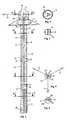
- various cables 12through the tubular mast 1 to pulled up.
- mobile radio antennas 16which are arranged on two levels one above the other are and comprise three antennas on each floor level, which in three send different directions or receive from these directions can; 5 the lobes of the antennas 16 are indicated by arrows 17.
- the mobile radio antennas 16are located in the GRP tube 10 formed by radio permeable outer wall part of the mast outer wall 8 and are through this GRP pipe 10 clad so that they are invisible from the outside, however can send and receive with virtually no interference.
- a directional antenna 18, the club through an arrow 19is indicated.
- the directional radio antenna 18sits on a turntable arrangement 20, whose axis of rotation coaxial with the cylinder axis of the mast outer wall 8 and thus also to the circumference of the GRP cap 11 and approximately in the middle through the antenna 18 including its holder, which is the Space within the cap 11 largely fills and in spite of the cramped
- the spatial conditions offered by the lamppostare adjusted in the direction of rotation and can be adjusted.
- the carrying functiontakes over here in the area of the directional radio antenna 18 a rod 25, which in turn is tubular and also as an inner tube can be designated.
- the rod 25, if tubular,may, for example be formed by a standard 90 mm tube. She does have one lower bending stiffness than the steel tube 9, for the partial length of the affected Masts and in view of the arrangement in the area of the mast tip, it is sufficient However.
- the rod 25is with the mast outer wall 8 via star-like or spoke wheel-like holder 26 connected in the illustrated embodiment are cruciform (Fig. 4).
- the mobile radio antennas 16are firmly seated on the rod 25 via clamping sleeves 29, and the turntable arrangement sits - if necessary, with changing radio directions, including an electric motor - at the top of the rod 25.
- the lamp 2 with the lamp 3is carried by the rod 25.
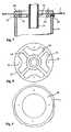
- the fastening method used for thisis illustrated in Figs. 7 to 9. 7 is on the rod 25 8 flange ring 32 shown in Fig. 8, which is used to free passages 33 for the cable 12 with radial spokes 34 is built. From the peripheral part of this flange ring there are individual flanges 35 with screw holes on the inside in front.
- the flange ring 32can, as shown in FIG. 7 on one side, also a circular circumferential groove 36 for inserting the GRP pipe Have 10.
- flange ring 32On the flange ring 32 is also provided with screw holes, shown in Fig. 9 shown lamp ring 40 screwed on, and supporting parts of the lamp 2 are clamped between the rings 35 and 40 or are on the light ring 40 welded or, as indicated in Fig. 7, integrally formed therewith.
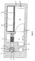
- the mast 1is, as mentioned, with the base of its mast outer wall 8 in Quiver 4 anchored.
- the quiver 4is part of the Housing 42 of an underground chamber 43, the cabinets 44 with Contains circuit complexes that are used for signal processing, for connecting the Antennas 16, 18 with a fixed network and / or fixed cables, etc. are needed.
- the control cabinets 44are referred to as "technical cabinets”.
- the underground chamber 43further contains electrical devices Electricity meter 45 and electricity sub-distributor 46. Runs from electricity meter 45 in the concrete block of the housing 42 a channel 47 for (not shown) power cables to mast 1.
- the chamber 43consists of two partial chambers 51 and 52, which are separated by a lockable steel door 53.
- About one Entry 54which is not shown in detail, can be a meter reader first chamber 51, the key for the second chamber 52, in which the control cabinets 44 are located, however, has only the authorized personnel of the participating mobile operators.
- the chambershave grid floors 55, below which can possibly infiltrate seeping water, which then over a prepared installation is pumpable.
- the Circuit complexalso includes air conditioning, in particular a Cooling is.
- air conditioningin particular a Cooling is.
- the steel tube 9is of the order of magnitude with an annular gap 61 surrounded by 1 cm radial width.
- this annular gap 61is cast with a suitable building material for example with bitumen resin, which becomes completely hard when setting.
- the antenna lantern mast 1 shownis in number of its Antennas and the cabinets for use by two mobile operators dimensioned. In places with very high antenna masts 1 can be set up, more antennas and control cabinets can be installed installed, lower masts may be suitable only for a single mobile operator. So far, several mobile operators operate antenna lampposts close to each other individually, can the circuit complexes in the cabinets 44 for multiple masts be combined in a common underground housing 42.
- the mast cross sectionis not limited to the circular shape. Other forms, for example as polygonal prisms, may result in others Support structures.
- the antenna beamsshould be perpendicular to Outer wall of the mast, i.e. in the polygonal case straight through the flat wall part, be directed.
- the quiver for the mastcan go over the ground, consist of concrete or, for example, stone or cast iron and through Reliefs are decorated to facilitate adaptation to the environment. So far no directional antenna is required for a single antenna lantern mast the lamp 2 can represent the upper end of the mast, it can however, mobile radio antenna storeys still survive beyond lamp 2.
- the mast outer wall 8has an outer diameter of the order of magnitude from 300 - 400 mm. You can in the lower part of the mast, namely within reach of people from the surrounding floor, containing a small door, behind which a switch box for the street lamp sits.
Landscapes
- Engineering & Computer Science (AREA)
- Computer Networks & Wireless Communication (AREA)
- Support Of Aerials (AREA)
Abstract
Description
Translated fromGermanDie Erfindung bezieht sich auf eine Antennenanlage einer Feststation für denMobilfunk zur Aufstellung im Ortsbereich, mit Antennen, einem die Antennenin einer vorgegebenen Höhe über dem Grund haltenden Mast und einemSchaltungskomplex zur Speisung der Antennen.The invention relates to an antenna system of a base station for theMobile radio for installation in the local area, with antennas, the antennasand a mast at a predetermined height above the groundCircuit complex for feeding the antennas.
Funkmasten, insbesondere solche für den Mobilfunk, sollen idealerweise soaufgestellt sein, daß eine flächendeckende Versorgung gewährleistet ist. Für das Mobilfunksystem GSM (Global System for Mobile Communication) betrugder Aktionsradius einer Feststation, nämlich einer Sende- und Empfangsstation,die üblicherweise als "BTS" (Base Transceiver System) abgekürzt wird, inAbhängigkeit von der charakteristischen Wellenausbreitung, der örtlichenMorphologie und der regional zu erwartenden Teilnehmerdichte einige Kilometer.Beim bevorstehenden neuen Mobilfunksystem UMTS (Universal MobileTelecommunication System) verkleinert sich der Radius der einzelnen Zelle aufeine Größenordnung von 250 bis 400 m. Die Errichtung eines ausreichenddichten Netzes von Funkmasten hierfür begegnet jedoch erheblichen Schwierigkeiten,nämlich sowohl technischen Schwierigkeiten, wenn für die Funkmastenkein freier Raum zur Verfügung steht, als auch Akzeptanzschwierigkeiten, dieeinerseits aus einer Reserviertheit der Bevölkerung gegenüber der befürchtetenStrahlenbelastung und andererseits aus städtebaulichen Beschränkungen derMöglichkeiten resultieren. Soweit die Stationen auf Dächern oder sonstwie anGebäuden zu montieren sind, stellt auch deren Gewichtsbelastbarkeit eineGrenze dar.Radio masts, especially those for mobile communications, should ideally be like thisbe set up so that a nationwide supply is guaranteed. Forthe mobile radio system was GSM (Global System for Mobile Communication)the radius of action of a base station, namely a sending and receiving station,which is usually abbreviated as "BTS" (Base Transceiver System), inDependence on the characteristic wave propagation, the local oneMorphology and the regionally expected number of participants a few kilometers.With the upcoming new UMTS (Universal MobileTelecommunication System) the radius of the individual cell is reducedan order of magnitude of 250 to 400 m. Establishing a sufficientdense network of radio masts for this, however, encounters considerable difficulties,namely both technical difficulties when for the radio mastsno free space is available, as well as acceptance difficulties thaton the one hand, due to a reserved attitude of the population towards the fearedRadiation exposure and on the other hand from urban planning restrictions ofOpportunities result. As far as the stations on roofs or otherwiseBuildings are to be assembled, also their weight-bearing capacityLimit.
Besondere Schwierigkeiten ergeben sich in Altstadtbereichen, in denen zusätzlichzu den optischen Beschränkungen noch die erwähnten räumlichen Beschränkungensehr ins Gewicht fallen, da auf kleinen Plätzen und in Gassen dieAufstellung von Mobilfunkmasten sehr problematisch ist.Particular difficulties arise in old town areas, in which additionalto the optical restrictions, the spatial restrictions mentionedare very important, because in small squares and in alleysSetting up cell towers is very problematic.
Demgegenüber soll durch die Erfindung auch die Mobilfunkversorgung solcherBereiche ermöglicht werden. Diese Möglichkeit ergibt sich dadurch, daß,ausgehend von einer Antennenanlage der eingangs genannten Gattung, derMast ein Straßenlaternenmast ist, der zumindest bereichsweise eine Mast-Außenwandaufweist und der außer wenigstens einer Leuchte zur Straßenbeleuchtungdie Antennen innerhalb der Mast-Außenwand enthält, die zumindestim Bereich der Antennen aus einem für die Funksignal der Antennen durchlässigen,aber undurchsichtigen Material besteht.In contrast, the invention is also intended to provide mobile communications for suchAreas. This possibility arises becausestarting from an antenna system of the type mentioned at the beginning, theMast is a street lamp mast that has an outer mast wall at least in some areasand which has at least one lamp for street lightingcontains the antennas within the mast outer wall, at leastin the area of the antennas from a transparent to the radio signal of the antennas,but opaque material.
Die Laternenmasten, die auch bei engen Straßenverhältnissen vorhanden sindoder zumindest geduldet werden und durch stilistische Anpassung der Außenseite,beispielsweise in Form gußeisener Mastunterteile, optisch an die Umgebunganpaßbar sind, haben beispielsweise eine Höhe zwischen 10 und 22 m.Im oberen Bereich können in das Laternenmastvolumen die Mobilfunkantenneneingebaut werden, die dann durch die funkdurchlässigen, aber optisch undurchsichtigenAußenwandteile verkleidet werden.The lampposts, which are also available in narrow street conditionsor at least be tolerated and by stylistic adjustment of the outside,for example in the form of cast iron mast parts, visually to the environmentare adaptable, for example, have a height between 10 and 22 m.The mobile radio antennas can be seen in the lantern mast volume in the upper areacan be installed, which then through the radio-permeable, but optically opaqueOutside wall parts are clad.
Diese Verkleidung macht eine spezielle Tragestruktur des Mast erforderlich,da die funkdurchlässige Mast-Außenwand, die zumeist aus glasfaserverstärktemKunststoff besteht, keine für einen Mast ausreichende Tragkraft hat. DerLaternenmast ist ja außer seinem eigenen Gewicht auch noch sonstigenBelastungen ausgesetzt, insbesondere der Windkraft und eventuellen Stoßkräften.Zur Erzielung einer ausreichenden Trag- und Widerstandskraft enthältvorzugsweise der Mast in den Teilen, in denen die Mast-Außenwand aus fürdie Funksignale durchlässigem Material besteht, eine in seinen Inneren inseiner Längsrichtung verlaufende tragende Struktur, die insbesondere aus einerim Mast verlaufenden zentralen Stange bestehen kann. Diese Stange übernimmtfür die Länge des Antennenbereichs, im allgemeinen also für die obersteTeillänge des Masts, die Tragefunktion, die im übrigen Bereich üblicherweisedie Mast-Außenwand erbringt. Im Antennenbereich um die zentrale Stange sinddie funkdurchlässigen Teile der Mast-Außenwand rohrkanalförmig ausgebildetund werden von der im Rohrkanal verlaufenden zentrale Stange über radialeHalter, die zwischen sich freien Raum für die Durchverlegung von Kabelnlassen, gehalten.This cladding requires a special support structure for the mast,because the radio-permeable mast outer wall, which is mostly made of glass fiber reinforcedPlastic exists, does not have sufficient load capacity for a mast. TheLantern mast is other than its own weightExposed to loads, especially wind power and possible impact forces.To achieve sufficient strength and resistancepreferably the mast in the parts where the mast outer wall is made forthe radio signals are made of permeable material, one inside itits longitudinal direction supporting structure, which consists in particular of acentral rod running in the mast. This rod takes overfor the length of the antenna area, generally for the top onePartial length of the mast, the carrying function that is usual in the rest of the areathe mast outer wall provides. In the antenna area around the central polethe radio-permeable parts of the outer wall of the mast are designed as tubular ductsand are from the central rod running in the pipe channel via radialHolders that have free space between them for laying cableslet, held.
Eine zweckmäßige Höheneinteilung der Mastlänge kann so aussehen, daß derMast, von unten nach oben, folgende Teillängen hat: eine nur der Höhenüberbrückungdienende Teillänge; eine Antennen-Teillänge mit funkdurchlässigerAußenwand und Antennen im Inneren; eine Leuchten-Teillänge, die die wenigstens eine Leuchte, welche ihrerseits wenigstens eine Lampe enthält,trägt; und als oberen Abschluß eine Richtfunk-Teillänge mit einer in einemAntennengehäuse befindlichen Richtfunkantenne. Die Leuchten können hierbeinahezu sämtliche für Straßenlaternen verwendeten Bauformen haben, siekönnen sich um den Mast erstrecken oder an diesem über einen oder mehrereAusleger befestigt sein.An appropriate height division of the mast length can look so that theMast, from bottom to top, has the following partial lengths: one only for bridging the heightserving part length; a partial antenna length with radio permeableOuter wall and antennas inside; a partial length of light that theat least one lamp, which in turn contains at least one lamp,wearing; and as the upper end a radio link partial length with one in oneDirectional radio antenna located. The lights can do thisthey have almost all of the designs used for street lampscan extend around the mast or on this over one or moreBoom attached.
Der Laternenmast bietet naturgemäß keinen ausreichenden Raum für den inder Fachwelt als "Technik" bezeichneten Schaltungskomplex, der die Verwaltungder Funkschnittstelle, die Reservierung und Freigabe von Funkkanälen,die Steuerung von Funkrufen und die Signalverarbeitung durchführt. DieserSchaltungskomplex ist in einem oder mehreren Schaltschränken untergebracht,die je nach Auslegung und Umgebungstemperatur auch noch der Kühlungbedürfen. Grundsätzlich kann der Schaltungskomplex in einem in der Nähe desLaternenmasts befindlichen Gebäude untergebracht und mit dem Laternenmastüber Kabel verbunden sein. Sofern hierfür kein Gebäude zur Verfügung steht,stellt es eine bevorzugte Lösung dar, daß der Schaltungskomplex zumindestteilweise in einem im Untergrund versenkten Gehäuse untergebracht ist. Dereventuelle Wärmeabgabeteil eines Wärmepumpen-Kreislaufs ist allerdingstrotzdem vorzugsweise über der Oberfläche angeordnet, beispielsweise untereiner im Freien stehenden Sitzbank. Gemäß einer bevorzugten Ausführungsformsind im versenkten Gehäuse auch Stromzähler und eine Stromspeiseschaltungfür die Lampe(n) der Leuchte(n) untergebracht. Eine bevorzugteArchitektur des Gehäuses ist die, daß das versenkte Gehäuse einen Köcher fürdie Verankerung des Masts umfaßt und in zwei zugängliche Räume geteilt ist,von denen einer die Stromzähler und die Stromspeiseschaltung für die Lampenenthält und der andere, der gegenüber dem ersteren Raum verschließbar ist,den Schaltungskomplex zur Speisung der Antennen enthält, so daß einerseitseine kompakte Konstruktion vorliegt, die alle Anforderungen erfüllt, undandererseits gewährleistet ist, daß die für die Ablesung des Stromzählers und für die Stromversorgung der Lampen zuständigen Personen nicht ohne weiteresZutritt zum Schaltungskomplex für den Mobilfunk haben.The lamppost naturally does not offer sufficient space for the inThe circuitry known to the experts as "technology", which is responsible for the administrationthe radio interface, the reservation and release of radio channels,controls paging and signal processing. ThisCircuitry is housed in one or more cabinets,depending on the design and ambient temperature also coolingrequire. Basically, the circuit complex in a near theThe lamppost is located in the building and the lamppostbe connected by cable. If no building is available for this,it is a preferred solution that the circuit complex at leastis partially housed in a submerged housing. Thepossible heat emission part of a heat pump cycle is howevernevertheless preferably arranged above the surface, for example belowan outdoor bench. According to a preferred embodimentthere are also electricity meters and a power supply circuit in the recessed housingfor the lamp (s) of the lamp (s) housed. A preferred oneArchitecture of the case is that the recessed case is a quiver forthe mast is anchored and divided into two accessible spaces,one of which is the electricity meter and the power supply for the lampscontains and the other, which is lockable from the former room,contains the circuit complex for feeding the antennas, so that on the one handthere is a compact design that meets all requirements, andon the other hand, it is ensured that for reading the electricity meter andnot responsible for the power supply of the lampsHave access to the circuit complex for mobile radio.
Weitere Einzelheiten, Vorteile und Weiterbildungen der Erfindung ergeben sichaus der folgenden Beschreibung eines bevorzugten Ausführungsbeispiels unterBezugnahme auf die Zeichnung. Es zeigen:
- Fig. 1
- eine Darstellung der erfindungsgemäßen Antennenanlage in einemVertikalschnitt;
- Fig. 2
- in vergrößertem Maßstab den oberen Teil eines in Fig. 1 gezeigtenAntennen-Laternen-Masts mit aufgeschnittener Vorderseite;
- Fig. 3
- einen Schnitt durch den Mast in einer Ebene III - III in Fig. 2;
- Fig. 4
- einen Schnitt durch den Mast in einer Ebene IV - IV in Fig. 2;
- Fig. 5
- einen Schnitt durch den Mast in einer Ebene V - V in Fig. 2;
- Fig. 6
- einen Schnitt durch den Mast in einer Ebene VI - VI in Fig. 2;
- Fig. 7
- in stark vergrößertem Maßstab einen Vertikalschnitt durch einenoberen Abschnitt des Masts, in dem eine Leuchte montiert ist;
- Fig. 8
- eine Draufsicht auf einen der Halterung der Leuchte dienendenFlanschring;
- Fig. 9
- eine Draufsicht auf den zentralen Teil der Leuchte, mit einem demEinspannen dienenden Leuchtenring;
- Fig. 10
- in vergrößertem Maßstab einen Vertikalschnitt durch ein im Untergrundversenktes Gehäuse mit einem Schaltungskomplex;
- Fig. 11
- in noch weiter vergrößertem Maßstab einen Querschnitt durch dasGehäuse von Fig. 7.
- Fig. 1
- a representation of the antenna system according to the invention in a vertical section;
- Fig. 2
- on an enlarged scale the upper part of an antenna lantern mast shown in Figure 1 with the front cut open;
- Fig. 3
- a section through the mast in a plane III - III in Fig. 2;
- Fig. 4
- a section through the mast in a plane IV - IV in Fig. 2;
- Fig. 5
- a section through the mast in a plane V - V in Fig. 2;
- Fig. 6
- a section through the mast in a plane VI - VI in Fig. 2;
- Fig. 7
- on a greatly enlarged scale, a vertical section through an upper section of the mast in which a lamp is mounted;
- Fig. 8
- a plan view of one of the holder of the lamp serving flange ring;
- Fig. 9
- a plan view of the central part of the lamp, with a lamp ring used for clamping;
- Fig. 10
- on an enlarged scale, a vertical section through a submerged housing with a circuit complex;
- Fig. 11
- a cross section through the housing of FIG. 7 on an even larger scale.
Fig. 1 zeigt einen Antennen-Laternen-Mast 1 mit einer Leuchte 2, die eineLampe 3 enthält und als Straßenlaterne dient, beispielsweise in einem innerstädtischenBereich. Die Lampe 3 ist als Ringröhrenlampe in einer Leuchte mitkonischem Schirm dargestellt, die Erfindung ist jedoch auf die verschiedensten Leuchten- und Lampenformen anwendbar, beispielsweise solche, die an vomMast 1 ausgehenden Auslegern sitzen. Der Mast 1 ist beispielsweise zwischen10 und 22 m hoch und ist bodenseitig in einen Beton-Köcher 4 eingesetzt unddort vergossen.Fig. 1 shows an antenna lantern mast 1 with a
Der dargestellte Mast 1 hat eine rohrförmige Außenwand 8, die mehrereTeillängen umfaßt, nämlich eine untere Teillänge in Form eines Stahlrohrs 9,ein undurchsichtiges, jedoch für Funksignale durchlässiges Rohr 10 ausglasfaserverstärktem Kunststoff (GFK), und schließlich als oberen Abschlußeine Kappe 11, die wiederum aus glasfaserverstärktem Kunststoff besteht. Vonunten her sind verschiedene Kabel 12 durch den rohrförmigen Mast 1 nachoben gezogen.The mast 1 shown has a tubular
Im oberen Teil des Masts befinden sich, wie mit größerer Deutlichkeit in Fig.2 gezeigt ist, Mobilfunkantennen 16, die zweigeschossig übereinander angeordnetsind und in jeder Geschoßebene drei Antennen umfassen, die in dreiverschiedene Richtungen senden bzw. aus diesen Richtungen empfangenkönnen; in Fig. 5 sind die Keulen der Antennen 16 durch Pfeile 17 angedeutet.Die Mobilfunkantennen 16 befinden sich im durch das GFK-Rohr 10 gebildeten,funkdurchlässigen Außenwandteil der Mast-Außenwand 8 und sind durchdieses GFK-Rohr 10 so verkleidet, daß sie von außen unsichtbar sind, jedochpraktisch unbeeinträchtigt senden und empfangen können. In der Mastspitzebefindet sich in der GFK-Kappe 11 eine Richtfunkantenne 18, deren Keule durcheinen Pfeil 19 angedeutet ist. Die Richtfunkantenne 18 sitzt auf einer Drehtelleranordnung20, deren Drehachse koaxial zur Zylinderachse der Mast-Außenwand8 und somit auch zum Umfang der GFK-Kappe 11 ist und etwa mittigdurch die Antenne 18 einschließlich deren Halterung verläuft, die also denRaum innerhalb der Kappe 11 weitgehend ausfüllt und darin trotz der beengtenRaumverhältnisse, die der Laternenmast bietet, in Drehrichtung verstellt undjustiert werden kann.In the upper part of the mast, as is more clearly shown in Fig.2,
Während das Stahlrohr 9 eine ausreichend stabile und tragekräftige Strukturdes Antennen-Laternen-Masts 1 ergibt, ist dies beim GFK-Rohr 10 nicht der Fall.Die Tragfunktion übernimmt hier bis hinaus in den Bereich der Richtfunkantenne18 eine Stange 25, die wiederum rohrförmig ist und auch als Innenrohrbezeichnet werden kann. Die Stange 25 kann, wenn sie rohrförmig ist, beispielsweisedurch ein Standard-90 mm-Rohr gebildet sein. Sie hat zwar einegeringere Biegesteifigkeit als das Stahlrohr 9, für die betroffene Teillänge desMasts und angesichts der Anordnung im Bereich der Mastspitze genügt siejedoch. Die Stange 25 ist mit der Mast-Außenwand 8 über sternartige oderspeichenradartige Halter 26 verbunden, die bei der dargestellten Ausführungsformkreuzförmig sind (Fig. 4). Sie sind innen fest mit der Stange 25 verbundenund sind außen beispielsweise durch Verschraubung mit dem jeweiligen Teilder Außenwand 8 verbunden. Im unteren Teil, nämlich im Stahlrohr 9, habendie Halter 26 die Funktion, die Stange 25 stabil zu halten; im oberen Teil,nämlich im GFK-Rohr 10, haben die Halter 26 die Aufgabe, das Rohr 10 zuhalten. Aufgrund des Zwischenraums zwischen den radialen Teilen, die denHalter 26 bilden, können die Kabel 12 die im unteren Bereich in Kabelschienen27 verlegt sind, durch die Halter 26 hindurch nach oben gezogen werden.Kabelhalterungen 28 halten die Kabelschienen 27 bzw. die Kabel 12.While the
Die Mobilfunkantennen 16 sitzen über Klemmhülsen 29 fest an der Stange 25,und die Drehtelleranordnung sitzt - gegebenenfalls, bei wechselnden Funkrichtungen,einschließlich eines Elektromotors - am oberen Ende der Stange25. Auch die Leuchte 2 mit der Lampe 3 wird von der Stange 25 getragen. Diebeim beschriebenen Ausführungsbeispiel hierfür angewandte Befestigungsweiseist in den Fig.n 7 bis 9 veranschaulicht. Gemäß Fig. 7 ist an der Stange 25 einin Fig. 8 dargestellter Flanschring 32 befestigt, der zur Freilassung von Durchgängen33 für die Kabel 12 mit radialen Speichen 34 gebaut ist. Vom Umfangsteildieses Flanschrings stehen nach innen einzelne Flansche 35 mit Schraublöchernvor. Der Flanschring 32 kann, wie in Fig. 7 auf einer Seite dargestellt ist, auch noch eine kreisringartig umlaufende Nut 36 zum Einstecken des GFK-Rohrs10 haben.The
Auf den Flanschring 32 ist ein ebenfalls mit Schraublöchern versehener, in Fig.9 gezeigter Leuchtenring 40 aufgeschraubt, und tragende Teile der Leuchte 2sind zwischen die Ringe 35 und 40 eingespannt oder sind an den Leuchtenring40 angeschweißt oder, wie in Fig. 7 angedeutet, integral mit diesem ausgebildet.On the
Der Mast 1 ist, wie erwähnt, mit dem Sockel seiner Mast-Außenwand 8 imKöcher 4 verankert. Gemäß den Fig.n 10 und 11 ist der Köcher 4 Teil desGehäuses 42 einer unterirdischen Kammer 43, die Schaltschränke 44 mitSchaltungskomplexen enthält, die zur Signalverarbeitung, zur Verbindung derAntennen 16, 18 mit einem Festnetz und/oder fest verlegten Kabeln usw.benötigt werden. Die Schaltschränke 44 werden als "Technikschränke" bezeichnet.Die unterirdische Kammer 43 enthält weiterhin als elektrische EinrichtungenStromzähler 45 und Strom-Unterverteiler 46. Vom Stromzähler 45 verläuftim Betonblock des Gehäuses 42 ein Kanal 47 für (nicht dargestellte) Stromkabelzum Mast 1.The mast 1 is, as mentioned, with the base of its mast
Die Kammer 43 besteht beim dargestellten Beispiel aus zwei Teilkammern 51und 52, die durch eine verschließbare Stahltüre 53 getrennt sind. Über einennicht im einzelnen dargestellten Einstieg 54 kann ein Zählerableser zwar in dieerste Kammer 51 gelangen, den Schlüssel für die zweite Kammer 52, in der sichdie Schaltschränke 44 befinden, hat jedoch nur das autorisierte Personal derbeteiligten Mobilfunkbetreiber. Die Kammern haben Gitterböden 55, unterdenen sich eventuell einsickerndes Wasser sammeln kann, das dann über einepräparierte Installation abpumpbar ist.In the example shown, the
Beim dargestellten Beispiel befindet sich in der Teilkammer 52, die den Schaltungskomplex enthält, auch eine Klimatisierung, die insbesondere eineKühlung ist. Hierzu befinden sich innerhalb der Kammer ein Klima-Innengerät56 und außen, überirdisch, ein Klima-Außengerät 57, die miteinander übereinen (nicht dargestellten) Wärmepumpenkreislauf verbunden sind.In the example shown is in the sub-chamber 52, theCircuit complex also includes air conditioning, in particular aCooling is. For this purpose there is an indoor air conditioning unit inside the
Im Köcher 4 ist das Stahlrohr 9 mit einem Ringspalt 61 in der Größenordnungvon 1 cm radialer Breite umgeben. Bei der Errichtung des Antennen-Laternen-Masts1 wird dieser Ringspalt 61 mit einem passenden Baustoff vergossen wiebeispielsweise mit Bitumenharz, das beim Abbinden vollkommen hart wird.In the
Der dargestellte Antennen-Laternen-Mast 1 ist hinsichtlich der Zahl seinerAntennen und der Schaltschränke für den Gebrauch durch zwei Mobilfunkbetreiberdimensioniert. An Plätzen, an denen sehr hohe Antennen-Latemen-Masten1 aufgestellt werden können, können auch mehr Antennen und Schaltschränkeinstalliert werden, niedrigere Masten eignen sich unter Umständennur für einen einzigen Mobilfunkbetreiber. Soweit mehrere Mobilfunkbetreibernahe beieinander liegende Antennen-Laternen-Masten jeweils einzeln betreiben,können die Schaltungskomplexe in den Schaltschränken 44 für mehrere Mastenin einem gemeinsamen unterirdischen Gehäuse 42 zusammengefaßt sein.The antenna lantern mast 1 shown is in number of itsAntennas and the cabinets for use by two mobile operatorsdimensioned. In places with very high antenna masts1 can be set up, more antennas and control cabinets can be installedinstalled, lower masts may be suitableonly for a single mobile operator. So far, several mobile operatorsoperate antenna lampposts close to each other individually,can the circuit complexes in the
Der Mastquerschnitt ist nicht auf die Kreisform beschränkt. Andere Formen,beispielsweise als polygonale Prismen, ergeben unter Umständen andereHalterungskonstruktionen. Die Antennenkeulen sollen aber rechtwinklig zurMast-Außenwand, also im Polygonalfall gerade durch den ebenen Wandteil,gerichtet sein. Der Köcher für den Mast kann über den Erdboden hinaus gehen,aus Beton oder beispielsweise aus Stein oder Gußeisen bestehen und durchReliefs verziert sein, um die Anpassung an die Umgebung zu erleichtern. Soweitfür einen einzelnen Antennen-Laternen-Mast keine Richtfunkantenne benötigtwird, kann die Leuchte 2 den oberen Abschluß des Masts darstellen, es könnenjedoch auch Mobilfunk-Antennengeschoße noch über die Leuchte 2 überstehen.The mast cross section is not limited to the circular shape. Other forms,for example as polygonal prisms, may result in othersSupport structures. The antenna beams should be perpendicular toOuter wall of the mast, i.e. in the polygonal case straight through the flat wall part,be directed. The quiver for the mast can go over the ground,consist of concrete or, for example, stone or cast iron and throughReliefs are decorated to facilitate adaptation to the environment. So farno directional antenna is required for a single antenna lantern mastthe
Die Mast-Außenwand 8 hat einen Außendurchmesser in der Größenordnungvon 300 - 400 mm. Sie kann im unteren Teil des Masts, nämlich in Personen-Reichweitevom umgebenden Boden aus, eine kleine Türe enthalten, hinter derein Schaltkasten für die Straßenlaterne sitzt.The mast
Claims (10)
Translated fromGermanPriority Applications (1)
| Application Number | Priority Date | Filing Date | Title |
|---|---|---|---|
| EP02020876AEP1401048A1 (en) | 2002-09-18 | 2002-09-18 | Antenna installation for a mobile communications base station |
Applications Claiming Priority (1)
| Application Number | Priority Date | Filing Date | Title |
|---|---|---|---|
| EP02020876AEP1401048A1 (en) | 2002-09-18 | 2002-09-18 | Antenna installation for a mobile communications base station |
Publications (1)
| Publication Number | Publication Date |
|---|---|
| EP1401048A1true EP1401048A1 (en) | 2004-03-24 |
Family
ID=31896873
Family Applications (1)
| Application Number | Title | Priority Date | Filing Date |
|---|---|---|---|
| EP02020876AWithdrawnEP1401048A1 (en) | 2002-09-18 | 2002-09-18 | Antenna installation for a mobile communications base station |
Country Status (1)
| Country | Link |
|---|---|
| EP (1) | EP1401048A1 (en) |
Cited By (170)
| Publication number | Priority date | Publication date | Assignee | Title |
|---|---|---|---|---|
| EP1793066A1 (en)* | 2005-12-05 | 2007-06-06 | Prefabricados Uniblok, S.A. | Building that acts as base for a pole |
| WO2012069671A1 (en) | 2010-11-24 | 2012-05-31 | Knock Telecom, S.A. | Modular telephony tower with integrated electrical equipment |
| WO2015192569A1 (en)* | 2014-06-20 | 2015-12-23 | 中兴通讯股份有限公司 | Communication base station |
| US9312919B1 (en) | 2014-10-21 | 2016-04-12 | At&T Intellectual Property I, Lp | Transmission device with impairment compensation and methods for use therewith |
| US9461706B1 (en) | 2015-07-31 | 2016-10-04 | At&T Intellectual Property I, Lp | Method and apparatus for exchanging communication signals |
| US9467870B2 (en) | 2013-11-06 | 2016-10-11 | At&T Intellectual Property I, L.P. | Surface-wave communications and methods thereof |
| US9479266B2 (en) | 2013-12-10 | 2016-10-25 | At&T Intellectual Property I, L.P. | Quasi-optical coupler |
| US9490869B1 (en) | 2015-05-14 | 2016-11-08 | At&T Intellectual Property I, L.P. | Transmission medium having multiple cores and methods for use therewith |
| US9503189B2 (en) | 2014-10-10 | 2016-11-22 | At&T Intellectual Property I, L.P. | Method and apparatus for arranging communication sessions in a communication system |
| US9509415B1 (en) | 2015-06-25 | 2016-11-29 | At&T Intellectual Property I, L.P. | Methods and apparatus for inducing a fundamental wave mode on a transmission medium |
| US9520945B2 (en) | 2014-10-21 | 2016-12-13 | At&T Intellectual Property I, L.P. | Apparatus for providing communication services and methods thereof |
| US9525210B2 (en) | 2014-10-21 | 2016-12-20 | At&T Intellectual Property I, L.P. | Guided-wave transmission device with non-fundamental mode propagation and methods for use therewith |
| US9525524B2 (en) | 2013-05-31 | 2016-12-20 | At&T Intellectual Property I, L.P. | Remote distributed antenna system |
| US9531427B2 (en) | 2014-11-20 | 2016-12-27 | At&T Intellectual Property I, L.P. | Transmission device with mode division multiplexing and methods for use therewith |
| US9564947B2 (en) | 2014-10-21 | 2017-02-07 | At&T Intellectual Property I, L.P. | Guided-wave transmission device with diversity and methods for use therewith |
| US9577307B2 (en) | 2014-10-21 | 2017-02-21 | At&T Intellectual Property I, L.P. | Guided-wave transmission device and methods for use therewith |
| US9608692B2 (en) | 2015-06-11 | 2017-03-28 | At&T Intellectual Property I, L.P. | Repeater and methods for use therewith |
| US9608740B2 (en) | 2015-07-15 | 2017-03-28 | At&T Intellectual Property I, L.P. | Method and apparatus for launching a wave mode that mitigates interference |
| US9615269B2 (en) | 2014-10-02 | 2017-04-04 | At&T Intellectual Property I, L.P. | Method and apparatus that provides fault tolerance in a communication network |
| US9628116B2 (en) | 2015-07-14 | 2017-04-18 | At&T Intellectual Property I, L.P. | Apparatus and methods for transmitting wireless signals |
| US9628854B2 (en) | 2014-09-29 | 2017-04-18 | At&T Intellectual Property I, L.P. | Method and apparatus for distributing content in a communication network |
| US9640850B2 (en) | 2015-06-25 | 2017-05-02 | At&T Intellectual Property I, L.P. | Methods and apparatus for inducing a non-fundamental wave mode on a transmission medium |
| US9653770B2 (en) | 2014-10-21 | 2017-05-16 | At&T Intellectual Property I, L.P. | Guided wave coupler, coupling module and methods for use therewith |
| US9654173B2 (en) | 2014-11-20 | 2017-05-16 | At&T Intellectual Property I, L.P. | Apparatus for powering a communication device and methods thereof |
| US9667317B2 (en) | 2015-06-15 | 2017-05-30 | At&T Intellectual Property I, L.P. | Method and apparatus for providing security using network traffic adjustments |
| US9680670B2 (en) | 2014-11-20 | 2017-06-13 | At&T Intellectual Property I, L.P. | Transmission device with channel equalization and control and methods for use therewith |
| US9685992B2 (en) | 2014-10-03 | 2017-06-20 | At&T Intellectual Property I, L.P. | Circuit panel network and methods thereof |
| US9692101B2 (en) | 2014-08-26 | 2017-06-27 | At&T Intellectual Property I, L.P. | Guided wave couplers for coupling electromagnetic waves between a waveguide surface and a surface of a wire |
| US9699785B2 (en) | 2012-12-05 | 2017-07-04 | At&T Intellectual Property I, L.P. | Backhaul link for distributed antenna system |
| US9705561B2 (en) | 2015-04-24 | 2017-07-11 | At&T Intellectual Property I, L.P. | Directional coupling device and methods for use therewith |
| US9705571B2 (en) | 2015-09-16 | 2017-07-11 | At&T Intellectual Property I, L.P. | Method and apparatus for use with a radio distributed antenna system |
| US9722318B2 (en) | 2015-07-14 | 2017-08-01 | At&T Intellectual Property I, L.P. | Method and apparatus for coupling an antenna to a device |
| US9729197B2 (en) | 2015-10-01 | 2017-08-08 | At&T Intellectual Property I, L.P. | Method and apparatus for communicating network management traffic over a network |
| US9735833B2 (en) | 2015-07-31 | 2017-08-15 | At&T Intellectual Property I, L.P. | Method and apparatus for communications management in a neighborhood network |
| US9742462B2 (en) | 2014-12-04 | 2017-08-22 | At&T Intellectual Property I, L.P. | Transmission medium and communication interfaces and methods for use therewith |
| US9749053B2 (en) | 2015-07-23 | 2017-08-29 | At&T Intellectual Property I, L.P. | Node device, repeater and methods for use therewith |
| US9749013B2 (en) | 2015-03-17 | 2017-08-29 | At&T Intellectual Property I, L.P. | Method and apparatus for reducing attenuation of electromagnetic waves guided by a transmission medium |
| US9748626B2 (en) | 2015-05-14 | 2017-08-29 | At&T Intellectual Property I, L.P. | Plurality of cables having different cross-sectional shapes which are bundled together to form a transmission medium |
| US9755697B2 (en) | 2014-09-15 | 2017-09-05 | At&T Intellectual Property I, L.P. | Method and apparatus for sensing a condition in a transmission medium of electromagnetic waves |
| US9762289B2 (en) | 2014-10-14 | 2017-09-12 | At&T Intellectual Property I, L.P. | Method and apparatus for transmitting or receiving signals in a transportation system |
| US9769128B2 (en) | 2015-09-28 | 2017-09-19 | At&T Intellectual Property I, L.P. | Method and apparatus for encryption of communications over a network |
| US9769020B2 (en) | 2014-10-21 | 2017-09-19 | At&T Intellectual Property I, L.P. | Method and apparatus for responding to events affecting communications in a communication network |
| US9780834B2 (en) | 2014-10-21 | 2017-10-03 | At&T Intellectual Property I, L.P. | Method and apparatus for transmitting electromagnetic waves |
| US9793955B2 (en) | 2015-04-24 | 2017-10-17 | At&T Intellectual Property I, Lp | Passive electrical coupling device and methods for use therewith |
| US9793951B2 (en) | 2015-07-15 | 2017-10-17 | At&T Intellectual Property I, L.P. | Method and apparatus for launching a wave mode that mitigates interference |
| US9793954B2 (en) | 2015-04-28 | 2017-10-17 | At&T Intellectual Property I, L.P. | Magnetic coupling device and methods for use therewith |
| US9800327B2 (en) | 2014-11-20 | 2017-10-24 | At&T Intellectual Property I, L.P. | Apparatus for controlling operations of a communication device and methods thereof |
| US9820146B2 (en) | 2015-06-12 | 2017-11-14 | At&T Intellectual Property I, L.P. | Method and apparatus for authentication and identity management of communicating devices |
| US9838896B1 (en) | 2016-12-09 | 2017-12-05 | At&T Intellectual Property I, L.P. | Method and apparatus for assessing network coverage |
| US9836957B2 (en) | 2015-07-14 | 2017-12-05 | At&T Intellectual Property I, L.P. | Method and apparatus for communicating with premises equipment |
| US9847566B2 (en) | 2015-07-14 | 2017-12-19 | At&T Intellectual Property I, L.P. | Method and apparatus for adjusting a field of a signal to mitigate interference |
| US9847850B2 (en) | 2014-10-14 | 2017-12-19 | At&T Intellectual Property I, L.P. | Method and apparatus for adjusting a mode of communication in a communication network |
| US9853342B2 (en) | 2015-07-14 | 2017-12-26 | At&T Intellectual Property I, L.P. | Dielectric transmission medium connector and methods for use therewith |
| US9860075B1 (en) | 2016-08-26 | 2018-01-02 | At&T Intellectual Property I, L.P. | Method and communication node for broadband distribution |
| US9865911B2 (en) | 2015-06-25 | 2018-01-09 | At&T Intellectual Property I, L.P. | Waveguide system for slot radiating first electromagnetic waves that are combined into a non-fundamental wave mode second electromagnetic wave on a transmission medium |
| US9866309B2 (en) | 2015-06-03 | 2018-01-09 | At&T Intellectual Property I, Lp | Host node device and methods for use therewith |
| US9871283B2 (en) | 2015-07-23 | 2018-01-16 | At&T Intellectual Property I, Lp | Transmission medium having a dielectric core comprised of plural members connected by a ball and socket configuration |
| US9871282B2 (en) | 2015-05-14 | 2018-01-16 | At&T Intellectual Property I, L.P. | At least one transmission medium having a dielectric surface that is covered at least in part by a second dielectric |
| US9876571B2 (en) | 2015-02-20 | 2018-01-23 | At&T Intellectual Property I, Lp | Guided-wave transmission device with non-fundamental mode propagation and methods for use therewith |
| US9876605B1 (en) | 2016-10-21 | 2018-01-23 | At&T Intellectual Property I, L.P. | Launcher and coupling system to support desired guided wave mode |
| US9876264B2 (en) | 2015-10-02 | 2018-01-23 | At&T Intellectual Property I, Lp | Communication system, guided wave switch and methods for use therewith |
| US9882257B2 (en) | 2015-07-14 | 2018-01-30 | At&T Intellectual Property I, L.P. | Method and apparatus for launching a wave mode that mitigates interference |
| US9882277B2 (en) | 2015-10-02 | 2018-01-30 | At&T Intellectual Property I, Lp | Communication device and antenna assembly with actuated gimbal mount |
| US9893795B1 (en) | 2016-12-07 | 2018-02-13 | At&T Intellectual Property I, Lp | Method and repeater for broadband distribution |
| US9906269B2 (en) | 2014-09-17 | 2018-02-27 | At&T Intellectual Property I, L.P. | Monitoring and mitigating conditions in a communication network |
| US9904535B2 (en) | 2015-09-14 | 2018-02-27 | At&T Intellectual Property I, L.P. | Method and apparatus for distributing software |
| US9912381B2 (en) | 2015-06-03 | 2018-03-06 | At&T Intellectual Property I, Lp | Network termination and methods for use therewith |
| US9912419B1 (en) | 2016-08-24 | 2018-03-06 | At&T Intellectual Property I, L.P. | Method and apparatus for managing a fault in a distributed antenna system |
| US9912027B2 (en) | 2015-07-23 | 2018-03-06 | At&T Intellectual Property I, L.P. | Method and apparatus for exchanging communication signals |
| US9911020B1 (en) | 2016-12-08 | 2018-03-06 | At&T Intellectual Property I, L.P. | Method and apparatus for tracking via a radio frequency identification device |
| US9913139B2 (en) | 2015-06-09 | 2018-03-06 | At&T Intellectual Property I, L.P. | Signal fingerprinting for authentication of communicating devices |
| US9917341B2 (en) | 2015-05-27 | 2018-03-13 | At&T Intellectual Property I, L.P. | Apparatus and method for launching electromagnetic waves and for modifying radial dimensions of the propagating electromagnetic waves |
| US9927517B1 (en) | 2016-12-06 | 2018-03-27 | At&T Intellectual Property I, L.P. | Apparatus and methods for sensing rainfall |
| US9948354B2 (en) | 2015-04-28 | 2018-04-17 | At&T Intellectual Property I, L.P. | Magnetic coupling device with reflective plate and methods for use therewith |
| US9948333B2 (en) | 2015-07-23 | 2018-04-17 | At&T Intellectual Property I, L.P. | Method and apparatus for wireless communications to mitigate interference |
| US9954287B2 (en) | 2014-11-20 | 2018-04-24 | At&T Intellectual Property I, L.P. | Apparatus for converting wireless signals and electromagnetic waves and methods thereof |
| US9967173B2 (en) | 2015-07-31 | 2018-05-08 | At&T Intellectual Property I, L.P. | Method and apparatus for authentication and identity management of communicating devices |
| US9973940B1 (en) | 2017-02-27 | 2018-05-15 | At&T Intellectual Property I, L.P. | Apparatus and methods for dynamic impedance matching of a guided wave launcher |
| US9991580B2 (en) | 2016-10-21 | 2018-06-05 | At&T Intellectual Property I, L.P. | Launcher and coupling system for guided wave mode cancellation |
| US9997819B2 (en) | 2015-06-09 | 2018-06-12 | At&T Intellectual Property I, L.P. | Transmission medium and method for facilitating propagation of electromagnetic waves via a core |
| US9998870B1 (en) | 2016-12-08 | 2018-06-12 | At&T Intellectual Property I, L.P. | Method and apparatus for proximity sensing |
| US9999038B2 (en) | 2013-05-31 | 2018-06-12 | At&T Intellectual Property I, L.P. | Remote distributed antenna system |
| US10009901B2 (en) | 2015-09-16 | 2018-06-26 | At&T Intellectual Property I, L.P. | Method, apparatus, and computer-readable storage medium for managing utilization of wireless resources between base stations |
| US10009065B2 (en) | 2012-12-05 | 2018-06-26 | At&T Intellectual Property I, L.P. | Backhaul link for distributed antenna system |
| US10009063B2 (en) | 2015-09-16 | 2018-06-26 | At&T Intellectual Property I, L.P. | Method and apparatus for use with a radio distributed antenna system having an out-of-band reference signal |
| US10009067B2 (en) | 2014-12-04 | 2018-06-26 | At&T Intellectual Property I, L.P. | Method and apparatus for configuring a communication interface |
| US10020587B2 (en) | 2015-07-31 | 2018-07-10 | At&T Intellectual Property I, L.P. | Radial antenna and methods for use therewith |
| US10020844B2 (en) | 2016-12-06 | 2018-07-10 | T&T Intellectual Property I, L.P. | Method and apparatus for broadcast communication via guided waves |
| US10027397B2 (en) | 2016-12-07 | 2018-07-17 | At&T Intellectual Property I, L.P. | Distributed antenna system and methods for use therewith |
| US10033107B2 (en) | 2015-07-14 | 2018-07-24 | At&T Intellectual Property I, L.P. | Method and apparatus for coupling an antenna to a device |
| US10033108B2 (en) | 2015-07-14 | 2018-07-24 | At&T Intellectual Property I, L.P. | Apparatus and methods for generating an electromagnetic wave having a wave mode that mitigates interference |
| US10044409B2 (en) | 2015-07-14 | 2018-08-07 | At&T Intellectual Property I, L.P. | Transmission medium and methods for use therewith |
| US10051629B2 (en) | 2015-09-16 | 2018-08-14 | At&T Intellectual Property I, L.P. | Method and apparatus for use with a radio distributed antenna system having an in-band reference signal |
| US10051483B2 (en) | 2015-10-16 | 2018-08-14 | At&T Intellectual Property I, L.P. | Method and apparatus for directing wireless signals |
| US10069535B2 (en) | 2016-12-08 | 2018-09-04 | At&T Intellectual Property I, L.P. | Apparatus and methods for launching electromagnetic waves having a certain electric field structure |
| US20180254545A1 (en)* | 2017-03-06 | 2018-09-06 | Commscope Technologies Llc | Modular monopole for wireless communications |
| US10074890B2 (en) | 2015-10-02 | 2018-09-11 | At&T Intellectual Property I, L.P. | Communication device and antenna with integrated light assembly |
| US10079661B2 (en) | 2015-09-16 | 2018-09-18 | At&T Intellectual Property I, L.P. | Method and apparatus for use with a radio distributed antenna system having a clock reference |
| US10090606B2 (en) | 2015-07-15 | 2018-10-02 | At&T Intellectual Property I, L.P. | Antenna system with dielectric array and methods for use therewith |
| US10090594B2 (en) | 2016-11-23 | 2018-10-02 | At&T Intellectual Property I, L.P. | Antenna system having structural configurations for assembly |
| US10103801B2 (en) | 2015-06-03 | 2018-10-16 | At&T Intellectual Property I, L.P. | Host node device and methods for use therewith |
| US10103422B2 (en) | 2016-12-08 | 2018-10-16 | At&T Intellectual Property I, L.P. | Method and apparatus for mounting network devices |
| US10135145B2 (en) | 2016-12-06 | 2018-11-20 | At&T Intellectual Property I, L.P. | Apparatus and methods for generating an electromagnetic wave along a transmission medium |
| US10136434B2 (en) | 2015-09-16 | 2018-11-20 | At&T Intellectual Property I, L.P. | Method and apparatus for use with a radio distributed antenna system having an ultra-wideband control channel |
| US10135147B2 (en) | 2016-10-18 | 2018-11-20 | At&T Intellectual Property I, L.P. | Apparatus and methods for launching guided waves via an antenna |
| US10135146B2 (en) | 2016-10-18 | 2018-11-20 | At&T Intellectual Property I, L.P. | Apparatus and methods for launching guided waves via circuits |
| US10142086B2 (en) | 2015-06-11 | 2018-11-27 | At&T Intellectual Property I, L.P. | Repeater and methods for use therewith |
| US10139820B2 (en) | 2016-12-07 | 2018-11-27 | At&T Intellectual Property I, L.P. | Method and apparatus for deploying equipment of a communication system |
| US10148016B2 (en) | 2015-07-14 | 2018-12-04 | At&T Intellectual Property I, L.P. | Apparatus and methods for communicating utilizing an antenna array |
| US10144036B2 (en) | 2015-01-30 | 2018-12-04 | At&T Intellectual Property I, L.P. | Method and apparatus for mitigating interference affecting a propagation of electromagnetic waves guided by a transmission medium |
| US10154493B2 (en) | 2015-06-03 | 2018-12-11 | At&T Intellectual Property I, L.P. | Network termination and methods for use therewith |
| US10170840B2 (en) | 2015-07-14 | 2019-01-01 | At&T Intellectual Property I, L.P. | Apparatus and methods for sending or receiving electromagnetic signals |
| US10168695B2 (en) | 2016-12-07 | 2019-01-01 | At&T Intellectual Property I, L.P. | Method and apparatus for controlling an unmanned aircraft |
| US10178445B2 (en) | 2016-11-23 | 2019-01-08 | At&T Intellectual Property I, L.P. | Methods, devices, and systems for load balancing between a plurality of waveguides |
| US10205655B2 (en) | 2015-07-14 | 2019-02-12 | At&T Intellectual Property I, L.P. | Apparatus and methods for communicating utilizing an antenna array and multiple communication paths |
| US10225025B2 (en) | 2016-11-03 | 2019-03-05 | At&T Intellectual Property I, L.P. | Method and apparatus for detecting a fault in a communication system |
| US10224634B2 (en) | 2016-11-03 | 2019-03-05 | At&T Intellectual Property I, L.P. | Methods and apparatus for adjusting an operational characteristic of an antenna |
| US10243784B2 (en) | 2014-11-20 | 2019-03-26 | At&T Intellectual Property I, L.P. | System for generating topology information and methods thereof |
| US10243270B2 (en) | 2016-12-07 | 2019-03-26 | At&T Intellectual Property I, L.P. | Beam adaptive multi-feed dielectric antenna system and methods for use therewith |
| US10264586B2 (en) | 2016-12-09 | 2019-04-16 | At&T Mobility Ii Llc | Cloud-based packet controller and methods for use therewith |
| US10291311B2 (en) | 2016-09-09 | 2019-05-14 | At&T Intellectual Property I, L.P. | Method and apparatus for mitigating a fault in a distributed antenna system |
| US10291334B2 (en) | 2016-11-03 | 2019-05-14 | At&T Intellectual Property I, L.P. | System for detecting a fault in a communication system |
| US10298293B2 (en) | 2017-03-13 | 2019-05-21 | At&T Intellectual Property I, L.P. | Apparatus of communication utilizing wireless network devices |
| US10305190B2 (en) | 2016-12-01 | 2019-05-28 | At&T Intellectual Property I, L.P. | Reflecting dielectric antenna system and methods for use therewith |
| US10312567B2 (en) | 2016-10-26 | 2019-06-04 | At&T Intellectual Property I, L.P. | Launcher with planar strip antenna and methods for use therewith |
| US10320586B2 (en) | 2015-07-14 | 2019-06-11 | At&T Intellectual Property I, L.P. | Apparatus and methods for generating non-interfering electromagnetic waves on an insulated transmission medium |
| US10326494B2 (en) | 2016-12-06 | 2019-06-18 | At&T Intellectual Property I, L.P. | Apparatus for measurement de-embedding and methods for use therewith |
| US10326689B2 (en) | 2016-12-08 | 2019-06-18 | At&T Intellectual Property I, L.P. | Method and system for providing alternative communication paths |
| US10340603B2 (en) | 2016-11-23 | 2019-07-02 | At&T Intellectual Property I, L.P. | Antenna system having shielded structural configurations for assembly |
| US10340983B2 (en) | 2016-12-09 | 2019-07-02 | At&T Intellectual Property I, L.P. | Method and apparatus for surveying remote sites via guided wave communications |
| US10340600B2 (en) | 2016-10-18 | 2019-07-02 | At&T Intellectual Property I, L.P. | Apparatus and methods for launching guided waves via plural waveguide systems |
| US10341142B2 (en) | 2015-07-14 | 2019-07-02 | At&T Intellectual Property I, L.P. | Apparatus and methods for generating non-interfering electromagnetic waves on an uninsulated conductor |
| US10340601B2 (en) | 2016-11-23 | 2019-07-02 | At&T Intellectual Property I, L.P. | Multi-antenna system and methods for use therewith |
| US10340573B2 (en) | 2016-10-26 | 2019-07-02 | At&T Intellectual Property I, L.P. | Launcher with cylindrical coupling device and methods for use therewith |
| US10348391B2 (en) | 2015-06-03 | 2019-07-09 | At&T Intellectual Property I, L.P. | Client node device with frequency conversion and methods for use therewith |
| US10355367B2 (en) | 2015-10-16 | 2019-07-16 | At&T Intellectual Property I, L.P. | Antenna structure for exchanging wireless signals |
| US10361489B2 (en) | 2016-12-01 | 2019-07-23 | At&T Intellectual Property I, L.P. | Dielectric dish antenna system and methods for use therewith |
| US10359749B2 (en) | 2016-12-07 | 2019-07-23 | At&T Intellectual Property I, L.P. | Method and apparatus for utilities management via guided wave communication |
| US10374316B2 (en) | 2016-10-21 | 2019-08-06 | At&T Intellectual Property I, L.P. | System and dielectric antenna with non-uniform dielectric |
| US10382976B2 (en) | 2016-12-06 | 2019-08-13 | At&T Intellectual Property I, L.P. | Method and apparatus for managing wireless communications based on communication paths and network device positions |
| US10389029B2 (en) | 2016-12-07 | 2019-08-20 | At&T Intellectual Property I, L.P. | Multi-feed dielectric antenna system with core selection and methods for use therewith |
| US10389037B2 (en) | 2016-12-08 | 2019-08-20 | At&T Intellectual Property I, L.P. | Apparatus and methods for selecting sections of an antenna array and use therewith |
| US10396887B2 (en) | 2015-06-03 | 2019-08-27 | At&T Intellectual Property I, L.P. | Client node device and methods for use therewith |
| US10411356B2 (en) | 2016-12-08 | 2019-09-10 | At&T Intellectual Property I, L.P. | Apparatus and methods for selectively targeting communication devices with an antenna array |
| US10439675B2 (en) | 2016-12-06 | 2019-10-08 | At&T Intellectual Property I, L.P. | Method and apparatus for repeating guided wave communication signals |
| US10446936B2 (en) | 2016-12-07 | 2019-10-15 | At&T Intellectual Property I, L.P. | Multi-feed dielectric antenna system and methods for use therewith |
| US10498044B2 (en) | 2016-11-03 | 2019-12-03 | At&T Intellectual Property I, L.P. | Apparatus for configuring a surface of an antenna |
| US10530505B2 (en) | 2016-12-08 | 2020-01-07 | At&T Intellectual Property I, L.P. | Apparatus and methods for launching electromagnetic waves along a transmission medium |
| US10535928B2 (en) | 2016-11-23 | 2020-01-14 | At&T Intellectual Property I, L.P. | Antenna system and methods for use therewith |
| US10547348B2 (en) | 2016-12-07 | 2020-01-28 | At&T Intellectual Property I, L.P. | Method and apparatus for switching transmission mediums in a communication system |
| US10601494B2 (en) | 2016-12-08 | 2020-03-24 | At&T Intellectual Property I, L.P. | Dual-band communication device and method for use therewith |
| US10637149B2 (en) | 2016-12-06 | 2020-04-28 | At&T Intellectual Property I, L.P. | Injection molded dielectric antenna and methods for use therewith |
| US20200136236A1 (en)* | 2018-10-29 | 2020-04-30 | Commscope Technologies Llc | Perforated door for monopole module and method of mounting same |
| US10650940B2 (en) | 2015-05-15 | 2020-05-12 | At&T Intellectual Property I, L.P. | Transmission medium having a conductive material and methods for use therewith |
| US10665942B2 (en) | 2015-10-16 | 2020-05-26 | At&T Intellectual Property I, L.P. | Method and apparatus for adjusting wireless communications |
| US10679767B2 (en) | 2015-05-15 | 2020-06-09 | At&T Intellectual Property I, L.P. | Transmission medium having a conductive material and methods for use therewith |
| US10694379B2 (en) | 2016-12-06 | 2020-06-23 | At&T Intellectual Property I, L.P. | Waveguide system with device-based authentication and methods for use therewith |
| US10727599B2 (en) | 2016-12-06 | 2020-07-28 | At&T Intellectual Property I, L.P. | Launcher with slot antenna and methods for use therewith |
| WO2020152294A1 (en)* | 2019-01-23 | 2020-07-30 | Schreder S.A. | Lamp post with tubular pole |
| US10755542B2 (en) | 2016-12-06 | 2020-08-25 | At&T Intellectual Property I, L.P. | Method and apparatus for surveillance via guided wave communication |
| US10777873B2 (en) | 2016-12-08 | 2020-09-15 | At&T Intellectual Property I, L.P. | Method and apparatus for mounting network devices |
| US10784670B2 (en) | 2015-07-23 | 2020-09-22 | At&T Intellectual Property I, L.P. | Antenna support for aligning an antenna |
| US10811767B2 (en) | 2016-10-21 | 2020-10-20 | At&T Intellectual Property I, L.P. | System and dielectric antenna with convex dielectric radome |
| US10819035B2 (en) | 2016-12-06 | 2020-10-27 | At&T Intellectual Property I, L.P. | Launcher with helical antenna and methods for use therewith |
| US10916969B2 (en) | 2016-12-08 | 2021-02-09 | At&T Intellectual Property I, L.P. | Method and apparatus for providing power using an inductive coupling |
| US10938108B2 (en) | 2016-12-08 | 2021-03-02 | At&T Intellectual Property I, L.P. | Frequency selective multi-feed dielectric antenna system and methods for use therewith |
| US11032819B2 (en) | 2016-09-15 | 2021-06-08 | At&T Intellectual Property I, L.P. | Method and apparatus for use with a radio distributed antenna system having a control channel reference signal |
| CN113056841A (en)* | 2018-11-29 | 2021-06-29 | 昕诺飞控股有限公司 | Street pole, street lighting pole, lamp and manufacturing method thereof |
| EP4001550A1 (en)* | 2020-11-18 | 2022-05-25 | Tenllado Infraestructuras, S.L. | Lightweight modular tower for telecommunications equipment |
| BE1028832B1 (en)* | 2020-11-30 | 2022-06-28 | Jan Callewaert | Implementation method of a digital lamppost and facade wall lamppost |
Citations (5)
| Publication number | Priority date | Publication date | Assignee | Title |
|---|---|---|---|---|
| WO1998053522A1 (en)* | 1997-05-20 | 1998-11-26 | Stealth Network Technologies, Inc. | Shell and support structure for enclosing an antenna mounted on an elongated member |
| US6222503B1 (en)* | 1997-01-10 | 2001-04-24 | William Gietema | System and method of integrating and concealing antennas, antenna subsystems and communications subsystems |
| WO2001078190A1 (en)* | 2000-04-06 | 2001-10-18 | So.L.E. Societa' Luce Elettrica S.P.A. | Light tower provided with base radio station for mobile telephony |
| WO2002025768A1 (en)* | 2000-09-21 | 2002-03-28 | Barry Roger Creighton | Telecommunications mast installation |
| WO2002033784A1 (en)* | 2000-10-16 | 2002-04-25 | Simexgroup Ag | Antenna mast |
- 2002
- 2002-09-18EPEP02020876Apatent/EP1401048A1/ennot_activeWithdrawn
Patent Citations (5)
| Publication number | Priority date | Publication date | Assignee | Title |
|---|---|---|---|---|
| US6222503B1 (en)* | 1997-01-10 | 2001-04-24 | William Gietema | System and method of integrating and concealing antennas, antenna subsystems and communications subsystems |
| WO1998053522A1 (en)* | 1997-05-20 | 1998-11-26 | Stealth Network Technologies, Inc. | Shell and support structure for enclosing an antenna mounted on an elongated member |
| WO2001078190A1 (en)* | 2000-04-06 | 2001-10-18 | So.L.E. Societa' Luce Elettrica S.P.A. | Light tower provided with base radio station for mobile telephony |
| WO2002025768A1 (en)* | 2000-09-21 | 2002-03-28 | Barry Roger Creighton | Telecommunications mast installation |
| WO2002033784A1 (en)* | 2000-10-16 | 2002-04-25 | Simexgroup Ag | Antenna mast |
Cited By (229)
| Publication number | Priority date | Publication date | Assignee | Title |
|---|---|---|---|---|
| EP1793066A1 (en)* | 2005-12-05 | 2007-06-06 | Prefabricados Uniblok, S.A. | Building that acts as base for a pole |
| WO2012069671A1 (en) | 2010-11-24 | 2012-05-31 | Knock Telecom, S.A. | Modular telephony tower with integrated electrical equipment |
| US9788326B2 (en) | 2012-12-05 | 2017-10-10 | At&T Intellectual Property I, L.P. | Backhaul link for distributed antenna system |
| US9699785B2 (en) | 2012-12-05 | 2017-07-04 | At&T Intellectual Property I, L.P. | Backhaul link for distributed antenna system |
| US10194437B2 (en) | 2012-12-05 | 2019-01-29 | At&T Intellectual Property I, L.P. | Backhaul link for distributed antenna system |
| US10009065B2 (en) | 2012-12-05 | 2018-06-26 | At&T Intellectual Property I, L.P. | Backhaul link for distributed antenna system |
| US9525524B2 (en) | 2013-05-31 | 2016-12-20 | At&T Intellectual Property I, L.P. | Remote distributed antenna system |
| US9930668B2 (en) | 2013-05-31 | 2018-03-27 | At&T Intellectual Property I, L.P. | Remote distributed antenna system |
| US10091787B2 (en) | 2013-05-31 | 2018-10-02 | At&T Intellectual Property I, L.P. | Remote distributed antenna system |
| US9999038B2 (en) | 2013-05-31 | 2018-06-12 | At&T Intellectual Property I, L.P. | Remote distributed antenna system |
| US10051630B2 (en) | 2013-05-31 | 2018-08-14 | At&T Intellectual Property I, L.P. | Remote distributed antenna system |
| US9661505B2 (en) | 2013-11-06 | 2017-05-23 | At&T Intellectual Property I, L.P. | Surface-wave communications and methods thereof |
| US9674711B2 (en) | 2013-11-06 | 2017-06-06 | At&T Intellectual Property I, L.P. | Surface-wave communications and methods thereof |
| US9467870B2 (en) | 2013-11-06 | 2016-10-11 | At&T Intellectual Property I, L.P. | Surface-wave communications and methods thereof |
| US9794003B2 (en) | 2013-12-10 | 2017-10-17 | At&T Intellectual Property I, L.P. | Quasi-optical coupler |
| US9876584B2 (en) | 2013-12-10 | 2018-01-23 | At&T Intellectual Property I, L.P. | Quasi-optical coupler |
| US9479266B2 (en) | 2013-12-10 | 2016-10-25 | At&T Intellectual Property I, L.P. | Quasi-optical coupler |
| WO2015192569A1 (en)* | 2014-06-20 | 2015-12-23 | 中兴通讯股份有限公司 | Communication base station |
| US10096881B2 (en) | 2014-08-26 | 2018-10-09 | At&T Intellectual Property I, L.P. | Guided wave couplers for coupling electromagnetic waves to an outer surface of a transmission medium |
| US9692101B2 (en) | 2014-08-26 | 2017-06-27 | At&T Intellectual Property I, L.P. | Guided wave couplers for coupling electromagnetic waves between a waveguide surface and a surface of a wire |
| US9768833B2 (en) | 2014-09-15 | 2017-09-19 | At&T Intellectual Property I, L.P. | Method and apparatus for sensing a condition in a transmission medium of electromagnetic waves |
| US9755697B2 (en) | 2014-09-15 | 2017-09-05 | At&T Intellectual Property I, L.P. | Method and apparatus for sensing a condition in a transmission medium of electromagnetic waves |
| US10063280B2 (en) | 2014-09-17 | 2018-08-28 | At&T Intellectual Property I, L.P. | Monitoring and mitigating conditions in a communication network |
| US9906269B2 (en) | 2014-09-17 | 2018-02-27 | At&T Intellectual Property I, L.P. | Monitoring and mitigating conditions in a communication network |
| US9628854B2 (en) | 2014-09-29 | 2017-04-18 | At&T Intellectual Property I, L.P. | Method and apparatus for distributing content in a communication network |
| US9973416B2 (en) | 2014-10-02 | 2018-05-15 | At&T Intellectual Property I, L.P. | Method and apparatus that provides fault tolerance in a communication network |
| US9615269B2 (en) | 2014-10-02 | 2017-04-04 | At&T Intellectual Property I, L.P. | Method and apparatus that provides fault tolerance in a communication network |
| US9998932B2 (en) | 2014-10-02 | 2018-06-12 | At&T Intellectual Property I, L.P. | Method and apparatus that provides fault tolerance in a communication network |
| US9685992B2 (en) | 2014-10-03 | 2017-06-20 | At&T Intellectual Property I, L.P. | Circuit panel network and methods thereof |
| US9866276B2 (en) | 2014-10-10 | 2018-01-09 | At&T Intellectual Property I, L.P. | Method and apparatus for arranging communication sessions in a communication system |
| US9503189B2 (en) | 2014-10-10 | 2016-11-22 | At&T Intellectual Property I, L.P. | Method and apparatus for arranging communication sessions in a communication system |
| US9762289B2 (en) | 2014-10-14 | 2017-09-12 | At&T Intellectual Property I, L.P. | Method and apparatus for transmitting or receiving signals in a transportation system |
| US9847850B2 (en) | 2014-10-14 | 2017-12-19 | At&T Intellectual Property I, L.P. | Method and apparatus for adjusting a mode of communication in a communication network |
| US9973299B2 (en) | 2014-10-14 | 2018-05-15 | At&T Intellectual Property I, L.P. | Method and apparatus for adjusting a mode of communication in a communication network |
| US9571209B2 (en) | 2014-10-21 | 2017-02-14 | At&T Intellectual Property I, L.P. | Transmission device with impairment compensation and methods for use therewith |
| US9564947B2 (en) | 2014-10-21 | 2017-02-07 | At&T Intellectual Property I, L.P. | Guided-wave transmission device with diversity and methods for use therewith |
| US9577307B2 (en) | 2014-10-21 | 2017-02-21 | At&T Intellectual Property I, L.P. | Guided-wave transmission device and methods for use therewith |
| US9705610B2 (en) | 2014-10-21 | 2017-07-11 | At&T Intellectual Property I, L.P. | Transmission device with impairment compensation and methods for use therewith |
| US9876587B2 (en) | 2014-10-21 | 2018-01-23 | At&T Intellectual Property I, L.P. | Transmission device with impairment compensation and methods for use therewith |
| US9769020B2 (en) | 2014-10-21 | 2017-09-19 | At&T Intellectual Property I, L.P. | Method and apparatus for responding to events affecting communications in a communication network |
| US9871558B2 (en) | 2014-10-21 | 2018-01-16 | At&T Intellectual Property I, L.P. | Guided-wave transmission device and methods for use therewith |
| US9596001B2 (en) | 2014-10-21 | 2017-03-14 | At&T Intellectual Property I, L.P. | Apparatus for providing communication services and methods thereof |
| US9912033B2 (en) | 2014-10-21 | 2018-03-06 | At&T Intellectual Property I, Lp | Guided wave coupler, coupling module and methods for use therewith |
| US9577306B2 (en) | 2014-10-21 | 2017-02-21 | At&T Intellectual Property I, L.P. | Guided-wave transmission device and methods for use therewith |
| US9960808B2 (en) | 2014-10-21 | 2018-05-01 | At&T Intellectual Property I, L.P. | Guided-wave transmission device and methods for use therewith |
| US9525210B2 (en) | 2014-10-21 | 2016-12-20 | At&T Intellectual Property I, L.P. | Guided-wave transmission device with non-fundamental mode propagation and methods for use therewith |
| US9520945B2 (en) | 2014-10-21 | 2016-12-13 | At&T Intellectual Property I, L.P. | Apparatus for providing communication services and methods thereof |
| US9948355B2 (en) | 2014-10-21 | 2018-04-17 | At&T Intellectual Property I, L.P. | Apparatus for providing communication services and methods thereof |
| US9780834B2 (en) | 2014-10-21 | 2017-10-03 | At&T Intellectual Property I, L.P. | Method and apparatus for transmitting electromagnetic waves |
| US9653770B2 (en) | 2014-10-21 | 2017-05-16 | At&T Intellectual Property I, L.P. | Guided wave coupler, coupling module and methods for use therewith |
| US9627768B2 (en) | 2014-10-21 | 2017-04-18 | At&T Intellectual Property I, L.P. | Guided-wave transmission device with non-fundamental mode propagation and methods for use therewith |
| US9954286B2 (en) | 2014-10-21 | 2018-04-24 | At&T Intellectual Property I, L.P. | Guided-wave transmission device with non-fundamental mode propagation and methods for use therewith |
| US9312919B1 (en) | 2014-10-21 | 2016-04-12 | At&T Intellectual Property I, Lp | Transmission device with impairment compensation and methods for use therewith |
| US9654173B2 (en) | 2014-11-20 | 2017-05-16 | At&T Intellectual Property I, L.P. | Apparatus for powering a communication device and methods thereof |
| US9742521B2 (en) | 2014-11-20 | 2017-08-22 | At&T Intellectual Property I, L.P. | Transmission device with mode division multiplexing and methods for use therewith |
| US9954287B2 (en) | 2014-11-20 | 2018-04-24 | At&T Intellectual Property I, L.P. | Apparatus for converting wireless signals and electromagnetic waves and methods thereof |
| US9531427B2 (en) | 2014-11-20 | 2016-12-27 | At&T Intellectual Property I, L.P. | Transmission device with mode division multiplexing and methods for use therewith |
| US9544006B2 (en) | 2014-11-20 | 2017-01-10 | At&T Intellectual Property I, L.P. | Transmission device with mode division multiplexing and methods for use therewith |
| US10243784B2 (en) | 2014-11-20 | 2019-03-26 | At&T Intellectual Property I, L.P. | System for generating topology information and methods thereof |
| US9680670B2 (en) | 2014-11-20 | 2017-06-13 | At&T Intellectual Property I, L.P. | Transmission device with channel equalization and control and methods for use therewith |
| US9800327B2 (en) | 2014-11-20 | 2017-10-24 | At&T Intellectual Property I, L.P. | Apparatus for controlling operations of a communication device and methods thereof |
| US9749083B2 (en) | 2014-11-20 | 2017-08-29 | At&T Intellectual Property I, L.P. | Transmission device with mode division multiplexing and methods for use therewith |
| US9712350B2 (en) | 2014-11-20 | 2017-07-18 | At&T Intellectual Property I, L.P. | Transmission device with channel equalization and control and methods for use therewith |
| US10009067B2 (en) | 2014-12-04 | 2018-06-26 | At&T Intellectual Property I, L.P. | Method and apparatus for configuring a communication interface |
| US9742462B2 (en) | 2014-12-04 | 2017-08-22 | At&T Intellectual Property I, L.P. | Transmission medium and communication interfaces and methods for use therewith |
| US10144036B2 (en) | 2015-01-30 | 2018-12-04 | At&T Intellectual Property I, L.P. | Method and apparatus for mitigating interference affecting a propagation of electromagnetic waves guided by a transmission medium |
| US9876571B2 (en) | 2015-02-20 | 2018-01-23 | At&T Intellectual Property I, Lp | Guided-wave transmission device with non-fundamental mode propagation and methods for use therewith |
| US9749013B2 (en) | 2015-03-17 | 2017-08-29 | At&T Intellectual Property I, L.P. | Method and apparatus for reducing attenuation of electromagnetic waves guided by a transmission medium |
| US10224981B2 (en) | 2015-04-24 | 2019-03-05 | At&T Intellectual Property I, Lp | Passive electrical coupling device and methods for use therewith |
| US9831912B2 (en) | 2015-04-24 | 2017-11-28 | At&T Intellectual Property I, Lp | Directional coupling device and methods for use therewith |
| US9793955B2 (en) | 2015-04-24 | 2017-10-17 | At&T Intellectual Property I, Lp | Passive electrical coupling device and methods for use therewith |
| US9705561B2 (en) | 2015-04-24 | 2017-07-11 | At&T Intellectual Property I, L.P. | Directional coupling device and methods for use therewith |
| US9948354B2 (en) | 2015-04-28 | 2018-04-17 | At&T Intellectual Property I, L.P. | Magnetic coupling device with reflective plate and methods for use therewith |
| US9793954B2 (en) | 2015-04-28 | 2017-10-17 | At&T Intellectual Property I, L.P. | Magnetic coupling device and methods for use therewith |
| US9887447B2 (en) | 2015-05-14 | 2018-02-06 | At&T Intellectual Property I, L.P. | Transmission medium having multiple cores and methods for use therewith |
| US9748626B2 (en) | 2015-05-14 | 2017-08-29 | At&T Intellectual Property I, L.P. | Plurality of cables having different cross-sectional shapes which are bundled together to form a transmission medium |
| US9490869B1 (en) | 2015-05-14 | 2016-11-08 | At&T Intellectual Property I, L.P. | Transmission medium having multiple cores and methods for use therewith |
| US9871282B2 (en) | 2015-05-14 | 2018-01-16 | At&T Intellectual Property I, L.P. | At least one transmission medium having a dielectric surface that is covered at least in part by a second dielectric |
| US10650940B2 (en) | 2015-05-15 | 2020-05-12 | At&T Intellectual Property I, L.P. | Transmission medium having a conductive material and methods for use therewith |
| US10679767B2 (en) | 2015-05-15 | 2020-06-09 | At&T Intellectual Property I, L.P. | Transmission medium having a conductive material and methods for use therewith |
| US9917341B2 (en) | 2015-05-27 | 2018-03-13 | At&T Intellectual Property I, L.P. | Apparatus and method for launching electromagnetic waves and for modifying radial dimensions of the propagating electromagnetic waves |
| US10103801B2 (en) | 2015-06-03 | 2018-10-16 | At&T Intellectual Property I, L.P. | Host node device and methods for use therewith |
| US10154493B2 (en) | 2015-06-03 | 2018-12-11 | At&T Intellectual Property I, L.P. | Network termination and methods for use therewith |
| US10396887B2 (en) | 2015-06-03 | 2019-08-27 | At&T Intellectual Property I, L.P. | Client node device and methods for use therewith |
| US9935703B2 (en) | 2015-06-03 | 2018-04-03 | At&T Intellectual Property I, L.P. | Host node device and methods for use therewith |
| US10050697B2 (en) | 2015-06-03 | 2018-08-14 | At&T Intellectual Property I, L.P. | Host node device and methods for use therewith |
| US10348391B2 (en) | 2015-06-03 | 2019-07-09 | At&T Intellectual Property I, L.P. | Client node device with frequency conversion and methods for use therewith |
| US10797781B2 (en) | 2015-06-03 | 2020-10-06 | At&T Intellectual Property I, L.P. | Client node device and methods for use therewith |
| US9967002B2 (en) | 2015-06-03 | 2018-05-08 | At&T Intellectual I, Lp | Network termination and methods for use therewith |
| US9912382B2 (en) | 2015-06-03 | 2018-03-06 | At&T Intellectual Property I, Lp | Network termination and methods for use therewith |
| US9912381B2 (en) | 2015-06-03 | 2018-03-06 | At&T Intellectual Property I, Lp | Network termination and methods for use therewith |
| US10812174B2 (en) | 2015-06-03 | 2020-10-20 | At&T Intellectual Property I, L.P. | Client node device and methods for use therewith |
| US9866309B2 (en) | 2015-06-03 | 2018-01-09 | At&T Intellectual Property I, Lp | Host node device and methods for use therewith |
| US9997819B2 (en) | 2015-06-09 | 2018-06-12 | At&T Intellectual Property I, L.P. | Transmission medium and method for facilitating propagation of electromagnetic waves via a core |
| US9913139B2 (en) | 2015-06-09 | 2018-03-06 | At&T Intellectual Property I, L.P. | Signal fingerprinting for authentication of communicating devices |
| US10027398B2 (en) | 2015-06-11 | 2018-07-17 | At&T Intellectual Property I, Lp | Repeater and methods for use therewith |
| US9608692B2 (en) | 2015-06-11 | 2017-03-28 | At&T Intellectual Property I, L.P. | Repeater and methods for use therewith |
| US10142086B2 (en) | 2015-06-11 | 2018-11-27 | At&T Intellectual Property I, L.P. | Repeater and methods for use therewith |
| US10142010B2 (en) | 2015-06-11 | 2018-11-27 | At&T Intellectual Property I, L.P. | Repeater and methods for use therewith |
| US9820146B2 (en) | 2015-06-12 | 2017-11-14 | At&T Intellectual Property I, L.P. | Method and apparatus for authentication and identity management of communicating devices |
| US9667317B2 (en) | 2015-06-15 | 2017-05-30 | At&T Intellectual Property I, L.P. | Method and apparatus for providing security using network traffic adjustments |
| US9640850B2 (en) | 2015-06-25 | 2017-05-02 | At&T Intellectual Property I, L.P. | Methods and apparatus for inducing a non-fundamental wave mode on a transmission medium |
| US10069185B2 (en) | 2015-06-25 | 2018-09-04 | At&T Intellectual Property I, L.P. | Methods and apparatus for inducing a non-fundamental wave mode on a transmission medium |
| US9882657B2 (en) | 2015-06-25 | 2018-01-30 | At&T Intellectual Property I, L.P. | Methods and apparatus for inducing a fundamental wave mode on a transmission medium |
| US9865911B2 (en) | 2015-06-25 | 2018-01-09 | At&T Intellectual Property I, L.P. | Waveguide system for slot radiating first electromagnetic waves that are combined into a non-fundamental wave mode second electromagnetic wave on a transmission medium |
| US10090601B2 (en) | 2015-06-25 | 2018-10-02 | At&T Intellectual Property I, L.P. | Waveguide system and methods for inducing a non-fundamental wave mode on a transmission medium |
| US9509415B1 (en) | 2015-06-25 | 2016-11-29 | At&T Intellectual Property I, L.P. | Methods and apparatus for inducing a fundamental wave mode on a transmission medium |
| US9787412B2 (en) | 2015-06-25 | 2017-10-10 | At&T Intellectual Property I, L.P. | Methods and apparatus for inducing a fundamental wave mode on a transmission medium |
| US9722318B2 (en) | 2015-07-14 | 2017-08-01 | At&T Intellectual Property I, L.P. | Method and apparatus for coupling an antenna to a device |
| US10044409B2 (en) | 2015-07-14 | 2018-08-07 | At&T Intellectual Property I, L.P. | Transmission medium and methods for use therewith |
| US9847566B2 (en) | 2015-07-14 | 2017-12-19 | At&T Intellectual Property I, L.P. | Method and apparatus for adjusting a field of a signal to mitigate interference |
| US9947982B2 (en) | 2015-07-14 | 2018-04-17 | At&T Intellectual Property I, Lp | Dielectric transmission medium connector and methods for use therewith |
| US9929755B2 (en) | 2015-07-14 | 2018-03-27 | At&T Intellectual Property I, L.P. | Method and apparatus for coupling an antenna to a device |
| US10205655B2 (en) | 2015-07-14 | 2019-02-12 | At&T Intellectual Property I, L.P. | Apparatus and methods for communicating utilizing an antenna array and multiple communication paths |
| US9853342B2 (en) | 2015-07-14 | 2017-12-26 | At&T Intellectual Property I, L.P. | Dielectric transmission medium connector and methods for use therewith |
| US9836957B2 (en) | 2015-07-14 | 2017-12-05 | At&T Intellectual Property I, L.P. | Method and apparatus for communicating with premises equipment |
| US10320586B2 (en) | 2015-07-14 | 2019-06-11 | At&T Intellectual Property I, L.P. | Apparatus and methods for generating non-interfering electromagnetic waves on an insulated transmission medium |
| US10341142B2 (en) | 2015-07-14 | 2019-07-02 | At&T Intellectual Property I, L.P. | Apparatus and methods for generating non-interfering electromagnetic waves on an uninsulated conductor |
| US10148016B2 (en) | 2015-07-14 | 2018-12-04 | At&T Intellectual Property I, L.P. | Apparatus and methods for communicating utilizing an antenna array |
| US10170840B2 (en) | 2015-07-14 | 2019-01-01 | At&T Intellectual Property I, L.P. | Apparatus and methods for sending or receiving electromagnetic signals |
| US9882257B2 (en) | 2015-07-14 | 2018-01-30 | At&T Intellectual Property I, L.P. | Method and apparatus for launching a wave mode that mitigates interference |
| US10033107B2 (en) | 2015-07-14 | 2018-07-24 | At&T Intellectual Property I, L.P. | Method and apparatus for coupling an antenna to a device |
| US9628116B2 (en) | 2015-07-14 | 2017-04-18 | At&T Intellectual Property I, L.P. | Apparatus and methods for transmitting wireless signals |
| US10033108B2 (en) | 2015-07-14 | 2018-07-24 | At&T Intellectual Property I, L.P. | Apparatus and methods for generating an electromagnetic wave having a wave mode that mitigates interference |
| US9793951B2 (en) | 2015-07-15 | 2017-10-17 | At&T Intellectual Property I, L.P. | Method and apparatus for launching a wave mode that mitigates interference |
| US9608740B2 (en) | 2015-07-15 | 2017-03-28 | At&T Intellectual Property I, L.P. | Method and apparatus for launching a wave mode that mitigates interference |
| US10090606B2 (en) | 2015-07-15 | 2018-10-02 | At&T Intellectual Property I, L.P. | Antenna system with dielectric array and methods for use therewith |
| US9912027B2 (en) | 2015-07-23 | 2018-03-06 | At&T Intellectual Property I, L.P. | Method and apparatus for exchanging communication signals |
| US9871283B2 (en) | 2015-07-23 | 2018-01-16 | At&T Intellectual Property I, Lp | Transmission medium having a dielectric core comprised of plural members connected by a ball and socket configuration |
| US9948333B2 (en) | 2015-07-23 | 2018-04-17 | At&T Intellectual Property I, L.P. | Method and apparatus for wireless communications to mitigate interference |
| US9806818B2 (en) | 2015-07-23 | 2017-10-31 | At&T Intellectual Property I, Lp | Node device, repeater and methods for use therewith |
| US9749053B2 (en) | 2015-07-23 | 2017-08-29 | At&T Intellectual Property I, L.P. | Node device, repeater and methods for use therewith |
| US10784670B2 (en) | 2015-07-23 | 2020-09-22 | At&T Intellectual Property I, L.P. | Antenna support for aligning an antenna |
| US10074886B2 (en) | 2015-07-23 | 2018-09-11 | At&T Intellectual Property I, L.P. | Dielectric transmission medium comprising a plurality of rigid dielectric members coupled together in a ball and socket configuration |
| US9461706B1 (en) | 2015-07-31 | 2016-10-04 | At&T Intellectual Property I, Lp | Method and apparatus for exchanging communication signals |
| US9838078B2 (en) | 2015-07-31 | 2017-12-05 | At&T Intellectual Property I, L.P. | Method and apparatus for exchanging communication signals |
| US9735833B2 (en) | 2015-07-31 | 2017-08-15 | At&T Intellectual Property I, L.P. | Method and apparatus for communications management in a neighborhood network |
| US10020587B2 (en) | 2015-07-31 | 2018-07-10 | At&T Intellectual Property I, L.P. | Radial antenna and methods for use therewith |
| US9967173B2 (en) | 2015-07-31 | 2018-05-08 | At&T Intellectual Property I, L.P. | Method and apparatus for authentication and identity management of communicating devices |
| US9904535B2 (en) | 2015-09-14 | 2018-02-27 | At&T Intellectual Property I, L.P. | Method and apparatus for distributing software |
| US10009063B2 (en) | 2015-09-16 | 2018-06-26 | At&T Intellectual Property I, L.P. | Method and apparatus for use with a radio distributed antenna system having an out-of-band reference signal |
| US10225842B2 (en) | 2015-09-16 | 2019-03-05 | At&T Intellectual Property I, L.P. | Method, device and storage medium for communications using a modulated signal and a reference signal |
| US10349418B2 (en) | 2015-09-16 | 2019-07-09 | At&T Intellectual Property I, L.P. | Method and apparatus for managing utilization of wireless resources via use of a reference signal to reduce distortion |
| US10079661B2 (en) | 2015-09-16 | 2018-09-18 | At&T Intellectual Property I, L.P. | Method and apparatus for use with a radio distributed antenna system having a clock reference |
| US10051629B2 (en) | 2015-09-16 | 2018-08-14 | At&T Intellectual Property I, L.P. | Method and apparatus for use with a radio distributed antenna system having an in-band reference signal |
| US10136434B2 (en) | 2015-09-16 | 2018-11-20 | At&T Intellectual Property I, L.P. | Method and apparatus for use with a radio distributed antenna system having an ultra-wideband control channel |
| US10009901B2 (en) | 2015-09-16 | 2018-06-26 | At&T Intellectual Property I, L.P. | Method, apparatus, and computer-readable storage medium for managing utilization of wireless resources between base stations |
| US9705571B2 (en) | 2015-09-16 | 2017-07-11 | At&T Intellectual Property I, L.P. | Method and apparatus for use with a radio distributed antenna system |
| US9769128B2 (en) | 2015-09-28 | 2017-09-19 | At&T Intellectual Property I, L.P. | Method and apparatus for encryption of communications over a network |
| US9729197B2 (en) | 2015-10-01 | 2017-08-08 | At&T Intellectual Property I, L.P. | Method and apparatus for communicating network management traffic over a network |
| US10074890B2 (en) | 2015-10-02 | 2018-09-11 | At&T Intellectual Property I, L.P. | Communication device and antenna with integrated light assembly |
| US9882277B2 (en) | 2015-10-02 | 2018-01-30 | At&T Intellectual Property I, Lp | Communication device and antenna assembly with actuated gimbal mount |
| US9876264B2 (en) | 2015-10-02 | 2018-01-23 | At&T Intellectual Property I, Lp | Communication system, guided wave switch and methods for use therewith |
| US10051483B2 (en) | 2015-10-16 | 2018-08-14 | At&T Intellectual Property I, L.P. | Method and apparatus for directing wireless signals |
| US10355367B2 (en) | 2015-10-16 | 2019-07-16 | At&T Intellectual Property I, L.P. | Antenna structure for exchanging wireless signals |
| US10665942B2 (en) | 2015-10-16 | 2020-05-26 | At&T Intellectual Property I, L.P. | Method and apparatus for adjusting wireless communications |
| US9912419B1 (en) | 2016-08-24 | 2018-03-06 | At&T Intellectual Property I, L.P. | Method and apparatus for managing a fault in a distributed antenna system |
| US9860075B1 (en) | 2016-08-26 | 2018-01-02 | At&T Intellectual Property I, L.P. | Method and communication node for broadband distribution |
| US10291311B2 (en) | 2016-09-09 | 2019-05-14 | At&T Intellectual Property I, L.P. | Method and apparatus for mitigating a fault in a distributed antenna system |
| US11032819B2 (en) | 2016-09-15 | 2021-06-08 | At&T Intellectual Property I, L.P. | Method and apparatus for use with a radio distributed antenna system having a control channel reference signal |
| US10135146B2 (en) | 2016-10-18 | 2018-11-20 | At&T Intellectual Property I, L.P. | Apparatus and methods for launching guided waves via circuits |
| US10135147B2 (en) | 2016-10-18 | 2018-11-20 | At&T Intellectual Property I, L.P. | Apparatus and methods for launching guided waves via an antenna |
| US10340600B2 (en) | 2016-10-18 | 2019-07-02 | At&T Intellectual Property I, L.P. | Apparatus and methods for launching guided waves via plural waveguide systems |
| US9991580B2 (en) | 2016-10-21 | 2018-06-05 | At&T Intellectual Property I, L.P. | Launcher and coupling system for guided wave mode cancellation |
| US10811767B2 (en) | 2016-10-21 | 2020-10-20 | At&T Intellectual Property I, L.P. | System and dielectric antenna with convex dielectric radome |
| US10374316B2 (en) | 2016-10-21 | 2019-08-06 | At&T Intellectual Property I, L.P. | System and dielectric antenna with non-uniform dielectric |
| US9876605B1 (en) | 2016-10-21 | 2018-01-23 | At&T Intellectual Property I, L.P. | Launcher and coupling system to support desired guided wave mode |
| US10312567B2 (en) | 2016-10-26 | 2019-06-04 | At&T Intellectual Property I, L.P. | Launcher with planar strip antenna and methods for use therewith |
| US10340573B2 (en) | 2016-10-26 | 2019-07-02 | At&T Intellectual Property I, L.P. | Launcher with cylindrical coupling device and methods for use therewith |
| US10224634B2 (en) | 2016-11-03 | 2019-03-05 | At&T Intellectual Property I, L.P. | Methods and apparatus for adjusting an operational characteristic of an antenna |
| US10225025B2 (en) | 2016-11-03 | 2019-03-05 | At&T Intellectual Property I, L.P. | Method and apparatus for detecting a fault in a communication system |
| US10498044B2 (en) | 2016-11-03 | 2019-12-03 | At&T Intellectual Property I, L.P. | Apparatus for configuring a surface of an antenna |
| US10291334B2 (en) | 2016-11-03 | 2019-05-14 | At&T Intellectual Property I, L.P. | System for detecting a fault in a communication system |
| US10535928B2 (en) | 2016-11-23 | 2020-01-14 | At&T Intellectual Property I, L.P. | Antenna system and methods for use therewith |
| US10340601B2 (en) | 2016-11-23 | 2019-07-02 | At&T Intellectual Property I, L.P. | Multi-antenna system and methods for use therewith |
| US10090594B2 (en) | 2016-11-23 | 2018-10-02 | At&T Intellectual Property I, L.P. | Antenna system having structural configurations for assembly |
| US10340603B2 (en) | 2016-11-23 | 2019-07-02 | At&T Intellectual Property I, L.P. | Antenna system having shielded structural configurations for assembly |
| US10178445B2 (en) | 2016-11-23 | 2019-01-08 | At&T Intellectual Property I, L.P. | Methods, devices, and systems for load balancing between a plurality of waveguides |
| US10305190B2 (en) | 2016-12-01 | 2019-05-28 | At&T Intellectual Property I, L.P. | Reflecting dielectric antenna system and methods for use therewith |
| US10361489B2 (en) | 2016-12-01 | 2019-07-23 | At&T Intellectual Property I, L.P. | Dielectric dish antenna system and methods for use therewith |
| US10819035B2 (en) | 2016-12-06 | 2020-10-27 | At&T Intellectual Property I, L.P. | Launcher with helical antenna and methods for use therewith |
| US10135145B2 (en) | 2016-12-06 | 2018-11-20 | At&T Intellectual Property I, L.P. | Apparatus and methods for generating an electromagnetic wave along a transmission medium |
| US10637149B2 (en) | 2016-12-06 | 2020-04-28 | At&T Intellectual Property I, L.P. | Injection molded dielectric antenna and methods for use therewith |
| US10439675B2 (en) | 2016-12-06 | 2019-10-08 | At&T Intellectual Property I, L.P. | Method and apparatus for repeating guided wave communication signals |
| US10755542B2 (en) | 2016-12-06 | 2020-08-25 | At&T Intellectual Property I, L.P. | Method and apparatus for surveillance via guided wave communication |
| US10727599B2 (en) | 2016-12-06 | 2020-07-28 | At&T Intellectual Property I, L.P. | Launcher with slot antenna and methods for use therewith |
| US9927517B1 (en) | 2016-12-06 | 2018-03-27 | At&T Intellectual Property I, L.P. | Apparatus and methods for sensing rainfall |
| US10326494B2 (en) | 2016-12-06 | 2019-06-18 | At&T Intellectual Property I, L.P. | Apparatus for measurement de-embedding and methods for use therewith |
| US10020844B2 (en) | 2016-12-06 | 2018-07-10 | T&T Intellectual Property I, L.P. | Method and apparatus for broadcast communication via guided waves |
| US10382976B2 (en) | 2016-12-06 | 2019-08-13 | At&T Intellectual Property I, L.P. | Method and apparatus for managing wireless communications based on communication paths and network device positions |
| US10694379B2 (en) | 2016-12-06 | 2020-06-23 | At&T Intellectual Property I, L.P. | Waveguide system with device-based authentication and methods for use therewith |
| US10389029B2 (en) | 2016-12-07 | 2019-08-20 | At&T Intellectual Property I, L.P. | Multi-feed dielectric antenna system with core selection and methods for use therewith |
| US10359749B2 (en) | 2016-12-07 | 2019-07-23 | At&T Intellectual Property I, L.P. | Method and apparatus for utilities management via guided wave communication |
| US9893795B1 (en) | 2016-12-07 | 2018-02-13 | At&T Intellectual Property I, Lp | Method and repeater for broadband distribution |
| US10027397B2 (en) | 2016-12-07 | 2018-07-17 | At&T Intellectual Property I, L.P. | Distributed antenna system and methods for use therewith |
| US10139820B2 (en) | 2016-12-07 | 2018-11-27 | At&T Intellectual Property I, L.P. | Method and apparatus for deploying equipment of a communication system |
| US10446936B2 (en) | 2016-12-07 | 2019-10-15 | At&T Intellectual Property I, L.P. | Multi-feed dielectric antenna system and methods for use therewith |
| US10243270B2 (en) | 2016-12-07 | 2019-03-26 | At&T Intellectual Property I, L.P. | Beam adaptive multi-feed dielectric antenna system and methods for use therewith |
| US10547348B2 (en) | 2016-12-07 | 2020-01-28 | At&T Intellectual Property I, L.P. | Method and apparatus for switching transmission mediums in a communication system |
| US10168695B2 (en) | 2016-12-07 | 2019-01-01 | At&T Intellectual Property I, L.P. | Method and apparatus for controlling an unmanned aircraft |
| US10103422B2 (en) | 2016-12-08 | 2018-10-16 | At&T Intellectual Property I, L.P. | Method and apparatus for mounting network devices |
| US10326689B2 (en) | 2016-12-08 | 2019-06-18 | At&T Intellectual Property I, L.P. | Method and system for providing alternative communication paths |
| US10530505B2 (en) | 2016-12-08 | 2020-01-07 | At&T Intellectual Property I, L.P. | Apparatus and methods for launching electromagnetic waves along a transmission medium |
| US10938108B2 (en) | 2016-12-08 | 2021-03-02 | At&T Intellectual Property I, L.P. | Frequency selective multi-feed dielectric antenna system and methods for use therewith |
| US9998870B1 (en) | 2016-12-08 | 2018-06-12 | At&T Intellectual Property I, L.P. | Method and apparatus for proximity sensing |
| US10916969B2 (en) | 2016-12-08 | 2021-02-09 | At&T Intellectual Property I, L.P. | Method and apparatus for providing power using an inductive coupling |
| US10411356B2 (en) | 2016-12-08 | 2019-09-10 | At&T Intellectual Property I, L.P. | Apparatus and methods for selectively targeting communication devices with an antenna array |
| US10389037B2 (en) | 2016-12-08 | 2019-08-20 | At&T Intellectual Property I, L.P. | Apparatus and methods for selecting sections of an antenna array and use therewith |
| US10069535B2 (en) | 2016-12-08 | 2018-09-04 | At&T Intellectual Property I, L.P. | Apparatus and methods for launching electromagnetic waves having a certain electric field structure |
| US10601494B2 (en) | 2016-12-08 | 2020-03-24 | At&T Intellectual Property I, L.P. | Dual-band communication device and method for use therewith |
| US9911020B1 (en) | 2016-12-08 | 2018-03-06 | At&T Intellectual Property I, L.P. | Method and apparatus for tracking via a radio frequency identification device |
| US10777873B2 (en) | 2016-12-08 | 2020-09-15 | At&T Intellectual Property I, L.P. | Method and apparatus for mounting network devices |
| US10264586B2 (en) | 2016-12-09 | 2019-04-16 | At&T Mobility Ii Llc | Cloud-based packet controller and methods for use therewith |
| US9838896B1 (en) | 2016-12-09 | 2017-12-05 | At&T Intellectual Property I, L.P. | Method and apparatus for assessing network coverage |
| US10340983B2 (en) | 2016-12-09 | 2019-07-02 | At&T Intellectual Property I, L.P. | Method and apparatus for surveying remote sites via guided wave communications |
| US9973940B1 (en) | 2017-02-27 | 2018-05-15 | At&T Intellectual Property I, L.P. | Apparatus and methods for dynamic impedance matching of a guided wave launcher |
| US11417943B2 (en)* | 2017-03-06 | 2022-08-16 | Commscope Technologies Llc | Modular monopole for wireless communications |
| US20180254545A1 (en)* | 2017-03-06 | 2018-09-06 | Commscope Technologies Llc | Modular monopole for wireless communications |
| US20220384936A1 (en)* | 2017-03-06 | 2022-12-01 | Commscope Technologies Llc | Modular monopole for wireless communications |
| US12015194B2 (en)* | 2017-03-06 | 2024-06-18 | Commscope Technologies Llc | Modular monopole for wireless communications |
| US10298293B2 (en) | 2017-03-13 | 2019-05-21 | At&T Intellectual Property I, L.P. | Apparatus of communication utilizing wireless network devices |
| US20200136236A1 (en)* | 2018-10-29 | 2020-04-30 | Commscope Technologies Llc | Perforated door for monopole module and method of mounting same |
| US12003016B2 (en)* | 2018-10-29 | 2024-06-04 | Commscope Technologies Llc | Perforated door for monopole module and method of mounting same |
| CN113056841A (en)* | 2018-11-29 | 2021-06-29 | 昕诺飞控股有限公司 | Street pole, street lighting pole, lamp and manufacturing method thereof |
| WO2020152294A1 (en)* | 2019-01-23 | 2020-07-30 | Schreder S.A. | Lamp post with tubular pole |
| NL2022438B1 (en)* | 2019-01-23 | 2020-08-18 | Schreder Sa | Lamp post with tubular pole |
| US11802670B2 (en) | 2019-01-23 | 2023-10-31 | Schreder S.A. | Lamp post with tubular pole |
| EP4001550A1 (en)* | 2020-11-18 | 2022-05-25 | Tenllado Infraestructuras, S.L. | Lightweight modular tower for telecommunications equipment |
| BE1028832B1 (en)* | 2020-11-30 | 2022-06-28 | Jan Callewaert | Implementation method of a digital lamppost and facade wall lamppost |
Similar Documents
| Publication | Publication Date | Title |
|---|---|---|
| EP1401048A1 (en) | Antenna installation for a mobile communications base station | |
| EP3145024A1 (en) | Antenna roof module, antennas retrofitting set for distribution cabinets and construction kit for producing distribution cabinets | |
| DE20214879U1 (en) | lighting device | |
| DE102008020847A1 (en) | Foundation body, method for producing a foundation body and method for setting up a mast | |
| EP0456007B1 (en) | Device for mounting and adjusting traffic signs or signals and/or illumination means for traffic areas | |
| CN204850632U (en) | Miniature integrated communication base station | |
| CN211119246U (en) | Intelligent lamp pole | |
| DE102018114089A1 (en) | Antenna roof module for a distribution cabinet, distribution cabinet with antenna roof module and manufacturing method | |
| WO1998013945A1 (en) | Base station for a mobile radio telephone system | |
| EP3217074A1 (en) | Modular outdoor light | |
| DE202006013144U1 (en) | Modular multipurpose pillar system for assembly of different functions e.g. lighting- and power supplying-purpose serving pillars, has base-, intermediate- and closing element, all having housing part in which function block is installed | |
| EP3972138A1 (en) | Street lamp with edge computing device | |
| AT5157U1 (en) | ANTENNA HOUSING | |
| WO2004099665A1 (en) | Lighting device | |
| DE102018106249A1 (en) | Outdoor light with function module | |
| DE20218101U1 (en) | Radome antenna mount for sector antennas has integral triangular section build | |
| DE102022001975A1 (en) | E-charging device for stationary and mobile power sources | |
| EP0469179A1 (en) | Modular lighting system | |
| DE10254490B3 (en) | Mobile radio sector antenna carrier has cladding applied by winding with relatively thin glass fiber reinforced plastic material in contact with ends of spider arms on common central axle/mast core | |
| EP0469178B1 (en) | Lighting system | |
| DE3221053C1 (en) | Device for pulling flexible lines into cavities | |
| DE10140441C2 (en) | Mounting system for the installation of antenna systems with antenna covers | |
| DE10210419C1 (en) | Tubular roof structure for receiving antennas and technical components | |
| EP2932615A1 (en) | Telecommunication system | |
| EP0976880B1 (en) | Method and device for installing multiple house service connections |
Legal Events
| Date | Code | Title | Description |
|---|---|---|---|
| PUAI | Public reference made under article 153(3) epc to a published international application that has entered the european phase | Free format text:ORIGINAL CODE: 0009012 | |
| AK | Designated contracting states | Kind code of ref document:A1 Designated state(s):AT BE BG CH CY CZ DE DK EE ES FI FR GB GR IE IT LI LU MC NL PT SE SK TR | |
| AX | Request for extension of the european patent | Extension state:AL LT LV MK RO SI | |
| 17P | Request for examination filed | Effective date:20040924 | |
| AKX | Designation fees paid | Designated state(s):AT BE BG CH CY CZ DE DK EE ES FI FR GB GR IE IT LI LU MC NL PT SE SK TR | |
| 17Q | First examination report despatched | Effective date:20050217 | |
| STAA | Information on the status of an ep patent application or granted ep patent | Free format text:STATUS: THE APPLICATION IS DEEMED TO BE WITHDRAWN | |
| 18D | Application deemed to be withdrawn | Effective date:20050629 |