EP1400814A2 - Directional setting apparatus, directional setting system, directional setting method and directional setting program - Google Patents
Directional setting apparatus, directional setting system, directional setting method and directional setting programDownload PDFInfo
- Publication number
- EP1400814A2 EP1400814A2EP03255840AEP03255840AEP1400814A2EP 1400814 A2EP1400814 A2EP 1400814A2EP 03255840 AEP03255840 AEP 03255840AEP 03255840 AEP03255840 AEP 03255840AEP 1400814 A2EP1400814 A2EP 1400814A2
- Authority
- EP
- European Patent Office
- Prior art keywords
- directional
- voice
- certain
- directivity
- recognition unit
- Prior art date
- Legal status (The legal status is an assumption and is not a legal conclusion. Google has not performed a legal analysis and makes no representation as to the accuracy of the status listed.)
- Granted
Links
Images


Classifications
- G—PHYSICS
- G10—MUSICAL INSTRUMENTS; ACOUSTICS
- G10L—SPEECH ANALYSIS TECHNIQUES OR SPEECH SYNTHESIS; SPEECH RECOGNITION; SPEECH OR VOICE PROCESSING TECHNIQUES; SPEECH OR AUDIO CODING OR DECODING
- G10L25/00—Speech or voice analysis techniques not restricted to a single one of groups G10L15/00 - G10L21/00
- G10L25/78—Detection of presence or absence of voice signals
- G—PHYSICS
- G01—MEASURING; TESTING
- G01S—RADIO DIRECTION-FINDING; RADIO NAVIGATION; DETERMINING DISTANCE OR VELOCITY BY USE OF RADIO WAVES; LOCATING OR PRESENCE-DETECTING BY USE OF THE REFLECTION OR RERADIATION OF RADIO WAVES; ANALOGOUS ARRANGEMENTS USING OTHER WAVES
- G01S3/00—Direction-finders for determining the direction from which infrasonic, sonic, ultrasonic, or electromagnetic waves, or particle emission, not having a directional significance, are being received
- G01S3/80—Direction-finders for determining the direction from which infrasonic, sonic, ultrasonic, or electromagnetic waves, or particle emission, not having a directional significance, are being received using ultrasonic, sonic or infrasonic waves
- G01S3/802—Systems for determining direction or deviation from predetermined direction
- G01S3/808—Systems for determining direction or deviation from predetermined direction using transducers spaced apart and measuring phase or time difference between signals therefrom, i.e. path-difference systems
- G01S3/8083—Systems for determining direction or deviation from predetermined direction using transducers spaced apart and measuring phase or time difference between signals therefrom, i.e. path-difference systems determining direction of source
- G—PHYSICS
- G10—MUSICAL INSTRUMENTS; ACOUSTICS
- G10L—SPEECH ANALYSIS TECHNIQUES OR SPEECH SYNTHESIS; SPEECH RECOGNITION; SPEECH OR VOICE PROCESSING TECHNIQUES; SPEECH OR AUDIO CODING OR DECODING
- G10L21/00—Speech or voice signal processing techniques to produce another audible or non-audible signal, e.g. visual or tactile, in order to modify its quality or its intelligibility
- G10L21/02—Speech enhancement, e.g. noise reduction or echo cancellation
- G10L21/0208—Noise filtering
- G10L21/0216—Noise filtering characterised by the method used for estimating noise
- G10L2021/02161—Number of inputs available containing the signal or the noise to be suppressed
- G10L2021/02166—Microphone arrays; Beamforming
Definitions
- the present inventionrelates to a directional setting apparatus, a directional setting system, a directional setting method and a directional setting program which form directivity of equipments by using a microphone consisted of a plurality of microphones.
- voice recognition processingan input sound imported from a microphone is compared with a recognition objective vocabulary in order to obtain a voice recognition result.
- ambient noisesare included in the sound signal imported by the microphone.
- anti-noise performancehas large influence on recognition accuracy. For example, assuming the case where the voice recognition is carried out in a car, there are a lot of noises in the car, for example, engine sound of the car, wind sound, sound of an opposite car, sound of passing car and sound of a car stereo. These noises are inputted to a voice recognition apparatus while being mixed in a voice of a speaking person, and degradation of a recognition rate is caused.
- a microphone array technique for suppressing noises by using a plurality of microphonesis known.
- signal processingsare performed for a sound inputted from a plurality of microphones. Therefore, a sharp directivity is formed in a direction of an objective sound, and an objective sound is emphasized by lowering sensitivity of the other direction.
- a plurality of microphonesare arranged in sequence of suffixes n at even intervals.
- the delay sum arrayforms directivity in a direction of the objective sound by using a phase difference of an incoming signal. That is, the delay sum array sets a delay time for the input signal of the microphones taking into consideration a time difference ⁇ by when the incoming signal reaches the microphones. After a phase of sound signals (including an objective signal) from the direction of arrival of the objective sound by delay processings for the signals is set inphase, the objective signal is emphasized by mutually adding them. On the other hand, with regard to the noise incoming from a direction different from the objective signal, the phases are mutually shifted by the delay processings, and the noise components are weakened to each other.
- Japanese Patent Publication Laid-Open No. 9794/1997discloses a method in which direction of the speaking person is sequentially detected by the microphone, the direction of the speaking person is tracked by updating the directivity of the microphone depending on the direction of the speaking person, thereby suppressing distortion for the objective signal.
- the direction of the speaking personis not necessarily the direction of arrival of the objective sound.
- the direction of arrival (DOA) of the objective soundhas to be set to only a direction of the certain person of a plurality of persons.
- Japanese Patent Publication Laid-Open No. 9794/1997discloses a method of setting a sound source area in advance, and registering it by association with the keyword.
- locations of the speaking persons for the microphone arrayare registered with the keyword.
- the table in which the locations of the speaking persons and the keywords are registeredis referred.
- the sound source area corresponding to the acknowledged keywordis identified.
- a sharp directivityis set to this sound source area. Therefore, it becomes possible to detect a sure DOA, and improve a voice recognition accuracy.
- An object of the present inventionis to provide a directional setting apparatus, a directional setting system, a directional setting method and a directional setting program capable of arbitrarily setting a direction of directivity and surely setting a directivity to a direction of arrival of the objective sound, without storing the direction of the directivity.
- a directional setting apparatuscomprising:
- Fig. 1is a block diagram showing a directional setting apparatus of a first embodiment according to the present invention.
- Fig. 1shows an example in which the present invention is applicable to the directional setting apparatus for a noise suppression using a microphone array.
- the directional setting apparatus of Fig. 1sets a certain keyword indicating a start of utterance, estimates a DOA of keyword at it is by voice recognition of the keyword, and forms a directivity for a certain period. Therefore, among a plurality of persons capable of uttering, only a voice of a certain person uttering the keyword is emphasized, and a sound processing for suppressing noise of the other direction of arrival can be performed. That is, without limiting an uttered location and user, even if unspecified number of persons has uttered from arbitrary locations, it is possible to surely detect the DOA.
- the directional setting apparatus of Fig. 1has a plurality of microphones 101_1-101_N, a recognition unit 300, a directional detector 201, a directional storage 202 and a directional controller 203.
- a plurality of microphones 101_1-101_Nare arranged to locations separated by every prescribed interval, and constitute a microphone array which imports a sound signal.
- the sound signal imported to the microphones 101_1-101_Nis supplied to the directional detector 201 and the directional controller 203.
- the sound signal from one microphone (the microphone 101_1 in the example of Fig. 1) among a plurality of microphones 101_1-101_Nis supplied to the recognition unit 300.
- the recognition unit 300can perform voice recognition processing for the input sound signal, and can detect that sound of a prescribed keyword set in advance has been inputted via the microphone 101_1. When the recognition unit 300 detects sound input of the keyword, the detected result is outputted to the directional detector 201 or the directional controller 203.
- the recognition unit 300carries out sound analysis for every constant time interval (frame), and obtains time sequence of voice characterizing amount such as cepstrum and power spectrum and a start time and a end time of voice, as a analyzed result.
- the recognition unit 300has a keyword storage not shown in which a prescribed keyword is registered.
- the recognition unit 300performs a pattern matching between the characterizing amount of the analyzed result and patterns of the characterizing amount of words registered in the keyword storage, in order to determine whether both coincides with each other.
- the recognition unit 300can output a frame corresponding to the keyword, i.e. a signal indicating the uttered period as the directional determination period to the directional detector 201.
- the recognition unit 300can specify only a period in which the input sound level is not less than a prescribed level, among the uttered period of the keyword, as the directional determination period.
- the recognition unit 300may specify a period longer or shorter than the uttered period of the keyword by a prescribed period, as the directional determination period.
- a keyword indicating a start of utterance, a keyword indicating an end of utteranceare registered and so on as a prescribed keyword.
- the recognition unit 300outputs the directional determination period to the directional detector 201 when the keyword indicating a start of utterance is detected, and outputs the detection result (a directional release signal) when the keyword indicating an end of utterance is detected, to the directional controller 203.
- the directional detector 201sequentially detects the direction of arrival of the input sound from the sound signal inputted to a plurality of microphones 101_1-101_N., and outputs directional data indicating the direction of arrival of the input sound. For example, the directional detector 201 detects the direction of arrival of the input sound for each frame, and sequentially outputs the detection result to the directional storage 202.
- the directional storage 202sequentially stores directional data indicating the direction of arrival of the input sound.
- the directional storage 202has a storage capacity which stores directional data for a period longer than at least the directional determination period.
- the directional detector 201outputs and stores the directional data to the directional storage 202, and can read out the directional data stored in the directional storage 202.
- the directional detector 201reads out one or more directional data within a period corresponding to the directional determination period from the directional storage 202, and detects the direction of arrival of the input sound in the directional determination period, for example, by an average value processing or most preferred processing using the readout directional data, when the signal indicating the directional determination period from the recognition unit 300 is given. That is, the directional detector 201 detects the direction from the microphone array for the utterer of the keyword.
- the directional detector 201outputs the calculation result of the direction of arrival of the input sound in the directional determination period as the arrival direction setting signal.
- the sound signal from a plurality of microphones 101_1-101_Nis inputted to the directional controller 203.
- the directional controller 203sets directional property of the inputted sound signal based on the arrival direction setting signal from the directional detector 201.
- the directional controller 203delays the sound signal from the microphones 101_1-101_N based on the amount of delay based on the direction of arrival specified by locations of the microphones 101_1-101_N and the arrival direction setting signal, and obtains the sound signal which adds the delay signals and has narrow directivity in a desirable direction. That is, a processing sound that sensitivity in the direction of arrival of the objective sound is eminently high, and sensitivity of the other directions is eminently low, is outputted.
- the directional controller 203stops the directional control processing and returns the directivity to wide directivity (non-directivity), when the signal informing detection of the keyword indicating the end of utterance (a directional release signal) is given from the recognition unit 300, the directional control processing is stopped, and the directivity is returned to the wide directivity (non-directivity).
- the directional controller 203has ended the directional control processing by the detection result of the keyword indicating the end of utterance, the directional control processing may be automatically ended after a prescribed period set in advance from the start of utterance.
- the directional storage 202stores the sequentially inputted directional data.
- the directional detector 201may store data capable of calculating the direction of arrival of the input sound in the directional determination period. For example, wave data by itself of the arrived sound signal may be stored in the directional storage 202.
- Fig. 2is a block diagram showing one example of the entire configuration of the directional setting apparatus in the case of storing the waveform data of the input sound signal as it is.
- the directional detector 201 of Fig. 2reads out the waveform data from the directional storage 202, and detects the direction of arrival of the input sound in the directional determination period, immediately after the directional determination period is indicated.
- a plurality of utterers at arbitrary locations different from each otheruse an application using one voice recognition apparatus.
- the voices from a plurality of utterersare imported from the microphones 101_1-101_N of the directional setting apparatus of Fig. 1, and a processing sound from the directional controller 203 is supplied to the voice recognition apparatus.
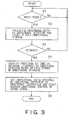
- Step S1 of Fig. 3indicates a waiting status of the voice input.
- the microphones 101_1-101_Nimport the sound input, and supply the sound input to the directional detector 201.
- the sound input imported via the microphone 101_1is supplied to the recognition unit 300.
- the sound signal including noise besides the objective soundis inputted to the microphones 101_1-101_N.
- the sounds from the utterers except for a certain personbecome noise.
- the directional detector 201sequentially detects the direction of arrival with regard to the input sound.
- the direction of arrival of the input sound detected by the directional detector 201is sequentially supplied to and stored in the directional storage 202 as the directional data (step S2). In this case, the direction of arrival of the objective sound including noise is detected.
- the recognition unit 300recognizes the keyword indicating the start of utterance from the sound signal inputted from the microphone 101_1. For example, it is assumed that a phrase "start" is set as a keyword indicating the start of utterance.
- the voiceis imported via the microphone 101_1 and supplied to the recognition unit 300.
- the recognition unit 300detects that the phrase "start” has been uttered, by a prescribed voice recognition processing for the sound inputted sequentially.
- the directional detector 201sets the directional determination period corresponding to the uttered period of the phrase "start” and outputs a signal indicating the period to the directional detector 201.
- the directional detector 201reads out from the directional storage 202 the directional data of a period corresponding to the directional determination period when the signal indicating the directional determination period is inputted. For example, the directional detector 201 determines the direction of arrival of the input sound (objective sound) in the directional determination period, that is, the direction of a prescribed utterer (hereinafter, called as a certain utterer) (step S4). The directional detector 201 outputs the arrival direction setting signal indicating the direction of arrival of the keyword to the directional controller 203.
- the directional controller 203sets the directional property for the sound signal inputted via the microphones 101_1-101_N, based on the arrival direction setting signal. Therefore, hereinafter, the directional controller 203 outputs the processing sound obtained by adding to the input sound, the directional property having narrow directivity and high sensitivity to a direction of a certain utterer (direction of arrival) uttering the keyword (step S5).
- the phrase "end”is set.
- the recognition unit 300recognizes the phrase "end” as the keyword.
- the recognition unit 300outputs the directional release signal for indicating the end of the directional control processing to the directional controller 203. Therefore, the directional controller 203 ends addition of the directional property for the input sound.
- the processing sound setting the directional property having narrow directivity to the direction of a certain utterer of the keywordis generated. Accordingly, the location of the utterer capable of forming the directivity is not fixed. It is unnecessary to register the location of the utterer in advance.
- the location of the utterer and the number of the utterersare not limited.
- Fig. 4is a block diagram showing a directional setting apparatus of a second embodiment according to the present invention.
- the same reference numbersare attached to the same constituents, and explanation will be omitted.
- the direction of a field of view of a camerais controlled by the direction of arrival of the keywords.
- the second embodimentis different from the first embodiment in which a camera drive controller 211 is provided, instead of the directional controller 203.
- a camera capable of picking up images in the directions of a plurality of utterersis arranged on a support table not shown.
- the support tablecan arbitrarily change an angle in horizontal and vertical directions by the drive unit not shown.
- the camera drive controller 211can control the horizontal and vertical directions of the camera support table by outputting the camera drive signal to the drive unit.
- the camera drive controller 211 of the second embodimentoutputs the camera drive signal which controls the direction of the camera support table based on the direction of arrival from the directional detector 201. Therefore, the camera can pick up images in the direction of arrival of the objective sound. That is, the camera drive controller 211 carries out the directional control processing which sets the view direction of the camera to a certain utterer according to keyword utterance of the certain utterer.
- the directional controller 203stops the directional control processing and returns the view direction of the camera to a prescribed initial direction when it receives the signal indicating detection of the keyword indicating the end of utterance (directional release) from the recognition unit 300.
- the directional controller 203may finish the directional control processing which sets the view direction of the camera to the direction of the certain utterer according to the detection result of the keyword indicating the end of utterance, the directional control processing may be automatically ended after a prescribed period set in advance from the start of utterance, and the view direction of the camera may be returned to a prescribed initial direction.
- a prescribed uttererin all the utterers utters the keyword indicating the start of utterance (directional setting), and utterance of the keyword is detected by the recognition unit 300. Afterward, during a prescribed period or until when the keyword of the end of utterance (directional release) is recognized, the view direction of the camera is automatically set to a certain utterer, and it is possible to pick up images of a certain utterer.
- the camera drive controller 211 of the second embodimentsets the view direction of the camera to a certain utterer, it is possible to set the view direction to a prescribed direction for the direction of a certain utterer.
- the directivity having narrow directivity to a direction of a certain utterer with regard to the input sound from the microphones 101_1-101_Nis formed, and at the same time, the camera can pick up images of the direction of a certain utterer, by combining the first and second embodiments.
- Fig. 5is a block diagram showing a directional setting apparatus of a third embodiment according to the present invention.
- the same reference numbersare attached to the same constituents as those of Fig. 1, and explanations will be omitted.
- the third embodimenthas characteristics different from that of the first embodiment, in which a processing sound from the directional controller 203 is supplied to the recognition unit 300.
- the directional controller 203sets an initial status to a wide directivity or non-directivity. Therefore, the input sounds from the microphones 101_1-101_N are simply combined and supplied to the recognition unit 300.
- detection processing of the keywordis performed with regard to the input sound from the microphone with the microphones 101_1-101_N, thereby improving accuracy of the detection result of the keyword.
- the directivity of the directional controller 203it is possible to set the directivity of the directional controller 203 to a prescribed direction. In this case, it is possible to limit the utterer capable of detecting the keyword, i.e. a certain utterer.
- the directional control processing by the directional controller 203is ended.
- the processing sound from the directional controller 203is supplied to the recognition unit 300, if once a certain utterer is determined, hereinafter, only when a certain utterer or the utterer locating the direction of a certain utterer has uttered the keyword "end", the keyword can be acknowledged, and the directional control processing can be ended. Therefore, it is possible to reduce possibility of malfunction of the application using the voice recognition apparatus.
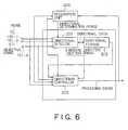
- Fig. 6is a block diagram showing a directional setting apparatus of a fourth embodiment according to the present invention.
- the same reference numbersare attached to the same constituents, and explanation will be omitted.
- detection accuracyis improved by carrying out a plurality of times the detection of the direction of arrival of the objective sound.
- the directional detector 205sequentially detects the direction of arrival of the input sound from the sound signal inputted to a plurality of microphones 101_1-101_N, and directional data indicating the direction of arrival of the input sound can be stored in the directional storage 202, similarly to the directional detector 201 in Fig. 1.
- the directional detector 205 of the fourth embodimentcan read out the directional data of a period different from the directional determination period from the recognition unit 300 from the directional storage 202, and revise the arrival direction setting signal.
- the directional detector 205 of the fourth embodimentcan supply and store the input sound by itself from the microphones 101_1-101_N to the directional storage 202.
- the directional detector 205reads out the waveform data stored in the directional storage 202 at a second calculation time of the direction of arrival, and the detection calculation in the direction of arrival is again carried out.
- the directional detector 205carries out calculation with accuracy higher than the calculation of the direction of arrival at first time.
- the directional storage 202supplies the held data to the directional controller 203.
- the directional controller 203supplies the processing sound forming the directivity for data from the directional storage 202 to the recognition unit 300 at second or more calculation times of the direction of arrival. Therefore, it is possible to obtain the information of the result of voice recognition which is used as a reference at calculation time of the direction of arrival even at second or more calculation times of the direction of arrival.
- the first calculation time of the direction of arrivalhas to largely set the directional range to be detected as the direction of arrival of the objective sound. Accordingly, the calculation of the direction of arrival by the directional detector 205 is carried out at comparatively rough accuracy. On the other hand, at second or more calculation times of the direction of arrival, the directional range to be detected on some level is limited by first calculation time of the direction of arrival. Because of this, it is possible to carry out the calculation at comparatively high accuracy. Thus, the directional detector 205 can detect the direction of arrival at higher accuracy by carrying out a plurality of times the calculation of the direction of arrival.
- the recognition unit 300detects the keyword by using the input sound from the microphone 101_1.
- the recognition unit 300sets the directional determination period based on the uttered period, and performs indication for the directional detector 205.
- the directional detector 205calculates the direction of arrival of the objective sound from the directional data or the waveform data stored in the directional storage 202, depending on the indication of the directional determination period from the recognition unit 300.
- the directional detector 205outputs the arrival direction setting signal indicating the detected direction of arrival, to the directional controller 203. Therefore, the directional controller 203 outputs the processing sound having the directivity to the certain utterer of the keyword.
- the directional detector 205 of the fourth embodimentcan carry out a plurality of times the calculation of the direction of arrival by using the directional data or the waveform data stored in the directional storage 202. For example, in vicinity of start time and end time of the uttered period of the keyword, even if noise level is high, the operation for controlling directivity and the operation for recognizing the signal obtained by the directivity are repeated, the noise is removed, and only a sound is extracted. Because of this, an uttered period more accurate than that of the keyword is obtained, and the calculation of the direction of arrival is not influenced on the noise uttered before and after the keyword, thereby improving accuracy of the calculation of the direction of arrival.
- the directional detector 205reads out the waveform data stored in the directional storage 202, and calculates the direction of arrival with regard to the comparatively narrow direction range in vicinity of the direction of arrival detected at first calculation time of the direction of arrival. Therefore, it is possible to improve the accuracy of the calculation of the direction of arrival.
- the directional detector 205reads out the waveform data stored in the directional storage 202, and calculates the direction of arrival with regard to a comparatively narrow directional range in vicinity of the direction of arrival detected at a first calculation time of the direction of arrival. Therefore, it is possible to improve the accuracy of the calculation of the direction of arrival.
- the directional detector 205outputs the arrival direction setting signal indicating the direction of arrival detected by a plurality of times calculation of the direction of arrival. Therefore, the directivity controller 203 can set a narrow directivity at even high accuracy as the direction of arrival of the objective sound.
- the calculation of the direction of arrival at second or more timesis carried out by using the calculation result of the calculation of the direction of arrival at first time. Therefore, it is possible to detect the direction of arrival at further high accuracy.
- the calculation using data in the directional storage 202i.e. the calculation using the keyword is performed.
- the calculation of the direction of arrival at second or more timesmay be performed based on the sound signal that the utterer has uttered newly.
- the recognition unit 300needs a voice recognition except for the keyword.
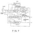
- Fig. 7is a block diagram showing a directional setting apparatus of a fifth embodiment according to the present invention.
- the same reference numbersare attached to the same constituents, and description will be omitted.
- the directivityhas been formed to only one certain utterer uttering the keyword.
- the directivitycan be formed to a plurality of certain utterers uttering the keyword.
- a plurality of directional controllers 203_1-203_Nare provided, different from the first embodiment.
- the directional controllers 203_1-203_Nhave the same configurations as those of the first embodiment.
- the arrival direction setting signalsare given from the directional detector 201, respectively, and the directivity of the input sound is set independently based on the inputted arrival direction setting signal.
- the recognition unit 300detects the keyword and indicates the directional determination period to the directional detector 201. Therefore, the directional detector 201 reads out the directional data for a period corresponding to the directional determination period, and detects the direction of arrival of the objective sound by the first utterer (hereinafter, a first certain utterer) uttering the keyword.
- the arrival direction setting signal indicating the direction of arrivalis, for example, provided to the directional controller 203_1. Therefore, the directional controller 203_1 forms the directivity having narrow directivity to the direction of the first certain utterer. In such a way, the processing sound from the directional controller 203_1 becomes a sound which emphasizes the voice uttered by the first certain utterer.
- the recognition unit 300detects the keyword and indicates the directional determination period to the directional detector 201.
- the directional detector 201reads out the directional data for a period corresponding to the directional determination period, and detects the direction of arrival of the objective sound from the second utterer (hereinafter, a second certain utterer) who has read out the directional data for a period corresponding to the directional determination period, and has uttered the keyword).
- the directional detector 201supplies the arrival direction setting signal indicating the direction of arrival, for example, to the directional controller 203_2.
- the directional controller 203_2forms directivity having narrow directivity to the direction of the second certain utterer. In such a way, the processing sound from the directional controller 203_2 becomes a sound which emphasizes the voice uttered by the second certain utterers.
- the fifth embodimentbecause a plurality of directional controllers are provided, it is possible to form the directivity at the same time to the direction of a plurality of certain utterers, and to perform voice recognition for the voice uttered by a plurality of certain utterers at high accuracy.
- the directivitymay be sequentially switched by one directional controller.
- the directional detector 201supplies the arrival direction setting signal based on the detected direction of arrival to the directional controller when the direction of arrival is detected by the detection of the keyword, after prior directional controlling processing is finished. Therefore, after the directional control processing for the direction of one certain utterer is finished, the directional controlling processing for a direction of a next certain utterer is performed. Because of this, it is possible to improve processing accuracy of voice recognition of certain utterers, without increasing the amount of calculation.
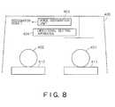
- Fig. 8is a diagram for explaining a sixth embodiment according to the present invention.
- a directional setting apparatusis applicable to control of a car equipment.
- a driver seat 411 and an assistant driver seat 412are provided in the car 400.
- the driver 401 and the passenger 402are sitting to the driver seat 411 and the assistant driver seat 412, respectively.
- the car equipments not shownsuch as a controller of air conditioner are attached at front side of the car 400 such as a dashboard not shown. Operation of the car equipments is controlled in accordance with the recognition result of the voice recognition unit 403.
- the processing sound of the directional setting apparatus of the first, third and fifth embodimentsfor example, the processing sound of the directional design apparatus 404 of the third embodiment is supplied to the voice recognition unit 403.
- Fig. 9is a diagram for explaining the processings of the sixth embodiment.
- Fig. 9shows sequential conversation between the driver 401 and the passenger 402, and operations of the directional setting apparatus 404 and the voice recognition unit 403 corresponding to the conversation (including the recognition unit in the directional setting apparatus 404 of Fig. 9) in time sequence.
- "-"indicates the status of non-recognition.
- the directional setting apparatus 404registers "car navigation" as the keyword indicating the start of utterance, and "thank you” as the keyword indicating the end of utterance (a directional release command in Fig. 9).
- the directional setting apparatus 404is set to the directivity in all directions (non-directivity), and the voice recognition unit 403 becomes the status which receives the keyword of the start of utterance from the driver 401 and the passenger 402.
- the driver 401utters "hot”.
- This utteranceis supplied to the recognition unit 300 without being suppressed via the microphone array (microphones 101_1-101_N shown in Fig. 4) set to all the directions in the directional setting apparatus 404.
- the recognition unit 300checks the uttered phrase "hot” with the keyword "car navigation”. Because the phrase "hot" does not coincide with the keyword, the result of the voice recognition is rejected in the recognition unit 300.
- the recognition unit 300sets the directional determination period based on the uttered period and indicates the detection of directivity to the directional detector 201, when detected that the "car navigation" uttered by the driver 401 is the keyword indicating the start of utterance.
- the directional detector 201detects the direction of the driver 401 as the direction of arrival of the objective sound by using the directional data stored in the directional storage 202.
- the directional controller 203forms narrow directivity to the direction of the driver 401 based on the arrival direction setting signal from the directional detector 201. Afterward, the sound from the direction of the driver 401 is emphasized, and the sound is provided to the voice recognition unit 403 from the directional setting apparatus 404.
- the driver 401utters "temperature down".
- the sound from the direction of the driver 401is supplied to the voice recognition unit 403 as the processing sound of an emphasized high quality.
- the voice recognition unit 403perform exactly voice recognition for "temperature down” uttered by the driver 401.
- the result of voice recognitionis transferred to the car equipments not shown, and various processings are executed in the car equipments. For example, in this case, the selection temperature of the air conditioner as the car equipments is lowered.
- the passenger 402utters "cold” after the temperature of the car 400 has been lowered.
- the directivity of the microphoneis set to narrow directivity for the driver 401, and voice of the passenger 402 is sufficiently suppressed, and provided to the voice recognition unit 403.
- the voice recognition unit 403does not perform the voice recognition of the phrase "cold". Because of this, control based on the phrase "cold" is not carried out in the car equipments.
- the recognition unit 300 in the directional setting apparatus 404returns the directivity of the directional controller 203 to all the direction. Therefore, the recognition unit 300 is returned to a status of accepting the keyword from all the directions.
- the passenger 402utters "car navigation".
- the directivity of the microphone arrayis set to the passenger 402.
- the voice recognition unit 403becomes the status accepting the commands for the passenger 402.
- the voice from the passenger 402is emphasized by the directional setting apparatus 404, and supplied to the voice recognition unit 403. Therefore, the air conditioner of the car equipments is controlled and the temperature is raised.
- the directivity of the microphone arrayis set to the person who has uttered the keyword of the start of utterance, it is possible to suppress not only a surrounding noise, but also speaking voices of the passenger, thereby exactly transmitting only the voice of a certain utterer.
- the directional controlling processingmay be performed for a new passenger by using the keyword of the start of utterance from the passenger 402.
- At least portion of the directional setting system or the directional setting apparatus described in the above-mentioned embodimentsmay be composed of a hardware or a software.
- a program for realizing at least portion of functions of the directional setting system or the directional setting apparatusmay be contained in a recording media such as a flexible disc or CD-ROM, and the program may be read in a computer and executed by the computer.
- the recording mediais not limited to a portable apparatus such as a magnetic disc or an optical disc, and may be a fixed type recording media such as a hard disc drive or a memory device.
- a program which realizes at least portion of functions of the directional setting system or the directional setting apparatusmay be distributed via a communication line such as an Internet (including wireless communication).
- the programmay be distributed at a encoded, modulated and compressed status, via a wired line or a wireless line such as Internet, or while containing in the recording media.
Landscapes
- Engineering & Computer Science (AREA)
- Physics & Mathematics (AREA)
- Health & Medical Sciences (AREA)
- Signal Processing (AREA)
- Audiology, Speech & Language Pathology (AREA)
- Human Computer Interaction (AREA)
- Computational Linguistics (AREA)
- Acoustics & Sound (AREA)
- Multimedia (AREA)
- General Physics & Mathematics (AREA)
- Radar, Positioning & Navigation (AREA)
- Remote Sensing (AREA)
- Circuit For Audible Band Transducer (AREA)
- Navigation (AREA)
Abstract
Description

Claims (20)
- A directional setting apparatus, comprising:a voice recognition unit which detects a certainvoice included in a sound signal outputted from amicrophone array having a plurality of microphones and adirectional determination period indicating a detectionperiod of said certain voice;a voice direction detector which detects occurrencedirection of said certain voice in said directionaldetermination period; anda directional controller which controls directivityof a prescribed apparatus based on the sound signalsinputted from said plurality of microphones in saiddirectional determination period.
- The directional setting apparatus according toclaim 1, wherein said directional controller controlsthe directivity of said prescribed apparatus, based onthe sound signal which is generated by delaying thesound signals outputted from said plurality ofmicrophones in said directional determination periodwith locations of said microphones and the amount ofdelay based on the direction of arrival of the soundsignals and adding the sound signals to each other.
- The directional setting apparatus according toclaim 1, further comprising:wherein said directional controller controlsdirectivity of said certain apparatus based on thedirectional data of said certain voice in saiddirectional determination period, among the directionaldata stored in said detection result storage.a detection result storage which stores directionaldata indicating occurrence direction of said certainvoice detected by said voice direction detector,
- The directional setting apparatus according toclaim 1, further comprising a sound storage which storessaid sound signal,
wherein said directional controller controlsdirectivity of said prescribed apparatus based on saidsound signals in said directional determination period,among the sound signal stored in said detection resultstorage. - The directional setting apparatus according toclaim 1, wherein said prescribed apparatus is saidmicrophone array; and
said directional controller controls thedirectivity of said microphone array based on thedetection result of said voice direction detector. - The directional setting apparatus according toclaim 1, wherein said prescribed apparatus is a imagepick-up device; and
said directional controller controls image pick-updirection of said image pick-up device based on thedetection result of said voice direction detector. - The directional setting apparatus according toclaim 1, wherein said voice recognition unit detectssaid certain voice included in the sound signaloutputted from a prescribed microphone among saidplurality of microphones.
- The directional setting apparatus according toclaim 1, wherein said voice recognition unit detectssaid certain voice included in the output of saiddirectional controller.
- The directional setting apparatus according toclaim 1, wherein said voice direction detector detects occurrence direction of said certain direction based ona result of repeating the detection of occurrencedirection of said certain voice by a plurality of times.
- The directional setting apparatus according toclaim 1, wherein said directional determination periodis a partial period in detection period of said certainvoice.
- The directional setting apparatus according toclaim 1, wherein said directional determination periodis a period within a detection period of said certainvoice and in which voice level of said certain voice isnot less than a prescribed level.
- The directional setting apparatus according toclaim 1, wherein said directional controller canindividually control the directivities of said pluralityof microphone, respectively.
- The directional setting apparatus according toclaim 1, wherein said directional controller supplies asound signal obtained by combining the sound signalsoutputted from said plurality of microphones to saidvoice recognition unit without control of thedirectivity, when said voice recognition unit detectssaid certain voice at fist time, and controls thedirectivity of the sound signals outputted from saidplurality of microphones based on the prior detectionresult by said voice recognition unit to supply thesound signal to said voice recognition unit, when saidvoice recognition unit detects said certain voice atsecond or more times.
- The directional setting apparatus according toclaim 1, wherein said voice recognition unit detects multiple types of said certain voices and a plurality ofsaid directional determination periods corresponding tothese certain voices; andsaid directional controller independently controlsthe directivity of said prescribed apparatus based onthe sound signal outputted from said plurality ofmicrophones in said plurality of directionaldetermination period.
- The directional setting apparatus according toclaim 1, wherein said voice recognition unit detects avoice indicating a setting of a certain directivity anda voice indicating a setting release of said certaindirectivity; and
said directivity controller suspends thedirectional control of said prescribed apparatus whensaid voice recognition unit detects the voice whichindicates setting release of said certain directivity. - The directional setting apparatus according toclaim 15, wherein said directional controller releasessetting of said certain directivity, and controlsdirectivity of said prescribed apparatus based on thedetection result of a new certain voice when said voicedirection detector detects occurrence direction of thenew certain voice, before said voice direction detectordetects the voice indicating the setting release of saidcertain directivity.
- The directional setting apparatus according toclaim 1, wherein said certain voice is a voice includinga meaningful certain keyword.
- A directional setting system, comprising:a microphone array having a plurality ofmicrophones;a voice recognition unit which detects a certainvoice included in a sound signal outputted from saidmicrophone array and a directional determination periodindicating a detection period of said certain voice;a voice direction detector which detects occurrencedirection of said certain voice in said directionaldetermination period; anda directivity controller which controls directivityof a prescribed apparatus based on sound signalsoutputted from said plurality of microphones in saiddirectional determination period.
- A directional setting method, comprising:detecting a certain voice included in a soundsignal outputted from a microphone array having aplurality of microphones, and a directionaldetermination period indicating a detection period ofsaid certain voice;detecting occurrence direction of said certainvoice in said directional determination period; andcontrolling directivity of a prescribed apparatusbased on the sound signals outputted from said pluralityof microphones in said directional determination period.
- A directional setting program, the steps ofcomprising:detecting a certain voice included in a soundsignal outputted from a microphone array having aplurality of microphones, and a directionaldetermination period indicating a detection period ofsaid certain voice;detecting occurrence direction of said certainvoice in said directional determination period; andcontrolling directivity of a prescribed apparatusbased on the sound signals outputted from said pluralityof microphones in said directional determination period.
Applications Claiming Priority (2)
| Application Number | Priority Date | Filing Date | Title |
|---|---|---|---|
| JP2002270318 | 2002-09-17 | ||
| JP2002270318AJP3910898B2 (en) | 2002-09-17 | 2002-09-17 | Directivity setting device, directivity setting method, and directivity setting program |
Publications (3)
| Publication Number | Publication Date |
|---|---|
| EP1400814A2true EP1400814A2 (en) | 2004-03-24 |
| EP1400814A3 EP1400814A3 (en) | 2004-04-21 |
| EP1400814B1 EP1400814B1 (en) | 2009-05-06 |
Family
ID=31944529
Family Applications (1)
| Application Number | Title | Priority Date | Filing Date |
|---|---|---|---|
| EP03255840AExpired - LifetimeEP1400814B1 (en) | 2002-09-17 | 2003-09-17 | Directional setting apparatus, directional setting system, directional setting method and directional setting program |
Country Status (4)
| Country | Link |
|---|---|
| US (1) | US7680287B2 (en) |
| EP (1) | EP1400814B1 (en) |
| JP (1) | JP3910898B2 (en) |
| DE (1) | DE60327494D1 (en) |
Cited By (10)
| Publication number | Priority date | Publication date | Assignee | Title |
|---|---|---|---|---|
| GB2394589B (en)* | 2002-10-25 | 2005-05-25 | Motorola Inc | Speech recognition device and method |
| EP2246846A1 (en)* | 2009-04-29 | 2010-11-03 | Deutsche Telekom AG | Shadow filter system for quasi-underdetermined blind adaptive MIMO filtering |
| WO2012054248A1 (en)* | 2010-10-22 | 2012-04-26 | Qualcomm Incorporated | Systems, methods, apparatus, and computer-readable media for far-field multi-source tracking and separation |
| US20150046157A1 (en)* | 2012-03-16 | 2015-02-12 | Nuance Communications, Inc. | User Dedicated Automatic Speech Recognition |
| WO2015092400A1 (en)* | 2013-12-18 | 2015-06-25 | Cirrus Logic International (Uk) Limited | Voice command triggered speech enhancement |
| WO2017184149A1 (en) | 2016-04-21 | 2017-10-26 | Hewlett-Packard Development Company, L.P. | Electronic device microphone listening modes |
| WO2018183636A1 (en)* | 2017-03-31 | 2018-10-04 | Bose Corporation | Directional capture of audio based on voice-activity detection |
| EP2587481B1 (en)* | 2002-10-23 | 2020-01-08 | Nuance Communications, Inc. | Controlling an apparatus based on speech |
| EP3754650A4 (en)* | 2018-02-12 | 2021-10-06 | Luxrobo Co., Ltd. | LOCATION-DEPENDENT VOICE RECOGNITION SYSTEM BY VOICE COMMAND |
| US11153472B2 (en) | 2005-10-17 | 2021-10-19 | Cutting Edge Vision, LLC | Automatic upload of pictures from a camera |
Families Citing this family (100)
| Publication number | Priority date | Publication date | Assignee | Title |
|---|---|---|---|---|
| GB0426448D0 (en)* | 2004-12-02 | 2005-01-05 | Koninkl Philips Electronics Nv | Position sensing using loudspeakers as microphones |
| DE602005008005D1 (en)* | 2005-02-23 | 2008-08-21 | Harman Becker Automotive Sys | Speech recognition system in a motor vehicle |
| US20080177542A1 (en)* | 2005-03-11 | 2008-07-24 | Gifu Service Corporation | Voice Recognition Program |
| JP4799443B2 (en)* | 2007-02-21 | 2011-10-26 | 株式会社東芝 | Sound receiving device and method |
| US20080273476A1 (en)* | 2007-05-02 | 2008-11-06 | Menachem Cohen | Device Method and System For Teleconferencing |
| US20100295782A1 (en) | 2009-05-21 | 2010-11-25 | Yehuda Binder | System and method for control based on face ore hand gesture detection |
| CN102428716B (en)* | 2009-06-17 | 2014-07-30 | 松下电器产业株式会社 | Hearing aid apparatus |
| JP5201093B2 (en)* | 2009-06-26 | 2013-06-05 | 株式会社ニコン | Imaging device |
| US8676581B2 (en)* | 2010-01-22 | 2014-03-18 | Microsoft Corporation | Speech recognition analysis via identification information |
| JP4945675B2 (en) | 2010-11-12 | 2012-06-06 | 株式会社東芝 | Acoustic signal processing apparatus, television apparatus, and program |
| EP2509337B1 (en)* | 2011-04-06 | 2014-09-24 | Sony Ericsson Mobile Communications AB | Accelerometer vector controlled noise cancelling method |
| US9031259B2 (en)* | 2011-09-15 | 2015-05-12 | JVC Kenwood Corporation | Noise reduction apparatus, audio input apparatus, wireless communication apparatus, and noise reduction method |
| US9881616B2 (en)* | 2012-06-06 | 2018-01-30 | Qualcomm Incorporated | Method and systems having improved speech recognition |
| KR101987966B1 (en)* | 2012-09-03 | 2019-06-11 | 현대모비스 주식회사 | System for improving voice recognition of the array microphone for vehicle and method thereof |
| JP6148163B2 (en)* | 2013-11-29 | 2017-06-14 | 本田技研工業株式会社 | Conversation support device, method for controlling conversation support device, and program for conversation support device |
| US10182280B2 (en) | 2014-04-23 | 2019-01-15 | Panasonic Intellectual Property Management Co., Ltd. | Sound processing apparatus, sound processing system and sound processing method |
| WO2015162645A1 (en)* | 2014-04-25 | 2015-10-29 | パナソニックIpマネジメント株式会社 | Audio processing apparatus, audio processing system, and audio processing method |
| JP2016126022A (en)* | 2014-12-26 | 2016-07-11 | アイシン精機株式会社 | Speech processing unit |
| JP6678315B2 (en)* | 2015-04-24 | 2020-04-08 | パナソニックIpマネジメント株式会社 | Voice reproduction method, voice interaction device, and voice interaction program |
| KR102444061B1 (en)* | 2015-11-02 | 2022-09-16 | 삼성전자주식회사 | Electronic device and method for recognizing voice of speech |
| JP6584930B2 (en)* | 2015-11-17 | 2019-10-02 | 株式会社東芝 | Information processing apparatus, information processing method, and program |
| US9811314B2 (en) | 2016-02-22 | 2017-11-07 | Sonos, Inc. | Metadata exchange involving a networked playback system and a networked microphone system |
| US10264030B2 (en) | 2016-02-22 | 2019-04-16 | Sonos, Inc. | Networked microphone device control |
| US10095470B2 (en) | 2016-02-22 | 2018-10-09 | Sonos, Inc. | Audio response playback |
| US9826306B2 (en) | 2016-02-22 | 2017-11-21 | Sonos, Inc. | Default playback device designation |
| US9978390B2 (en) | 2016-06-09 | 2018-05-22 | Sonos, Inc. | Dynamic player selection for audio signal processing |
| US10134399B2 (en) | 2016-07-15 | 2018-11-20 | Sonos, Inc. | Contextualization of voice inputs |
| US10115400B2 (en) | 2016-08-05 | 2018-10-30 | Sonos, Inc. | Multiple voice services |
| KR102515996B1 (en)* | 2016-08-26 | 2023-03-31 | 삼성전자주식회사 | Electronic Apparatus for Speech Recognition and Controlling Method thereof |
| US9942678B1 (en) | 2016-09-27 | 2018-04-10 | Sonos, Inc. | Audio playback settings for voice interaction |
| US10181323B2 (en) | 2016-10-19 | 2019-01-15 | Sonos, Inc. | Arbitration-based voice recognition |
| US10210863B2 (en)* | 2016-11-02 | 2019-02-19 | Roku, Inc. | Reception of audio commands |
| CN106910500B (en) | 2016-12-23 | 2020-04-17 | 北京小鸟听听科技有限公司 | Method and device for voice control of device with microphone array |
| US20180218747A1 (en)* | 2017-01-28 | 2018-08-02 | Bose Corporation | Audio Device Filter Modification |
| JP2018129678A (en)* | 2017-02-08 | 2018-08-16 | レノボ・シンガポール・プライベート・リミテッド | Information processing apparatus, method of using microphone, program to be executed by computer |
| US11183181B2 (en) | 2017-03-27 | 2021-11-23 | Sonos, Inc. | Systems and methods of multiple voice services |
| US10599377B2 (en) | 2017-07-11 | 2020-03-24 | Roku, Inc. | Controlling visual indicators in an audio responsive electronic device, and capturing and providing audio using an API, by native and non-native computing devices and services |
| JP6653687B2 (en)* | 2017-07-31 | 2020-02-26 | 日本電信電話株式会社 | Acoustic signal processing device, method and program |
| JP6969597B2 (en)* | 2017-07-31 | 2021-11-24 | 日本電信電話株式会社 | Acoustic signal processing equipment, methods and programs |
| JP6633579B2 (en)* | 2017-07-31 | 2020-01-22 | 日本電信電話株式会社 | Acoustic signal processing device, method and program |
| US10475449B2 (en) | 2017-08-07 | 2019-11-12 | Sonos, Inc. | Wake-word detection suppression |
| US10455322B2 (en) | 2017-08-18 | 2019-10-22 | Roku, Inc. | Remote control with presence sensor |
| US11062710B2 (en) | 2017-08-28 | 2021-07-13 | Roku, Inc. | Local and cloud speech recognition |
| US10777197B2 (en) | 2017-08-28 | 2020-09-15 | Roku, Inc. | Audio responsive device with play/stop and tell me something buttons |
| US11062702B2 (en) | 2017-08-28 | 2021-07-13 | Roku, Inc. | Media system with multiple digital assistants |
| JP6711789B2 (en)* | 2017-08-30 | 2020-06-17 | 日本電信電話株式会社 | Target voice extraction method, target voice extraction device, and target voice extraction program |
| US10048930B1 (en) | 2017-09-08 | 2018-08-14 | Sonos, Inc. | Dynamic computation of system response volume |
| US10446165B2 (en) | 2017-09-27 | 2019-10-15 | Sonos, Inc. | Robust short-time fourier transform acoustic echo cancellation during audio playback |
| US10482868B2 (en) | 2017-09-28 | 2019-11-19 | Sonos, Inc. | Multi-channel acoustic echo cancellation |
| US10051366B1 (en) | 2017-09-28 | 2018-08-14 | Sonos, Inc. | Three-dimensional beam forming with a microphone array |
| US10466962B2 (en) | 2017-09-29 | 2019-11-05 | Sonos, Inc. | Media playback system with voice assistance |
| JP6853163B2 (en)* | 2017-11-27 | 2021-03-31 | 日本電信電話株式会社 | Speaker orientation estimator, speaker orientation estimation method, and program |
| US10880650B2 (en) | 2017-12-10 | 2020-12-29 | Sonos, Inc. | Network microphone devices with automatic do not disturb actuation capabilities |
| US10818290B2 (en) | 2017-12-11 | 2020-10-27 | Sonos, Inc. | Home graph |
| WO2019142418A1 (en)* | 2018-01-22 | 2019-07-25 | ソニー株式会社 | Information processing device and information processing method |
| US11145298B2 (en) | 2018-02-13 | 2021-10-12 | Roku, Inc. | Trigger word detection with multiple digital assistants |
| CN108597507A (en)* | 2018-03-14 | 2018-09-28 | 百度在线网络技术(北京)有限公司 | Far field phonetic function implementation method, equipment, system and storage medium |
| JP7186375B2 (en)* | 2018-03-29 | 2022-12-09 | パナソニックIpマネジメント株式会社 | Speech processing device, speech processing method and speech processing system |
| US11175880B2 (en) | 2018-05-10 | 2021-11-16 | Sonos, Inc. | Systems and methods for voice-assisted media content selection |
| CN110797021B (en)* | 2018-05-24 | 2022-06-07 | 腾讯科技(深圳)有限公司 | Hybrid speech recognition network training method, hybrid speech recognition device and storage medium |
| US10959029B2 (en) | 2018-05-25 | 2021-03-23 | Sonos, Inc. | Determining and adapting to changes in microphone performance of playback devices |
| JP7041589B2 (en)* | 2018-06-11 | 2022-03-24 | シャープ株式会社 | Image display device and television receiver |
| US10681460B2 (en) | 2018-06-28 | 2020-06-09 | Sonos, Inc. | Systems and methods for associating playback devices with voice assistant services |
| US10461710B1 (en) | 2018-08-28 | 2019-10-29 | Sonos, Inc. | Media playback system with maximum volume setting |
| US11076035B2 (en) | 2018-08-28 | 2021-07-27 | Sonos, Inc. | Do not disturb feature for audio notifications |
| US10587430B1 (en) | 2018-09-14 | 2020-03-10 | Sonos, Inc. | Networked devices, systems, and methods for associating playback devices based on sound codes |
| US11024331B2 (en) | 2018-09-21 | 2021-06-01 | Sonos, Inc. | Voice detection optimization using sound metadata |
| US10811015B2 (en) | 2018-09-25 | 2020-10-20 | Sonos, Inc. | Voice detection optimization based on selected voice assistant service |
| US11100923B2 (en) | 2018-09-28 | 2021-08-24 | Sonos, Inc. | Systems and methods for selective wake word detection using neural network models |
| US10692518B2 (en) | 2018-09-29 | 2020-06-23 | Sonos, Inc. | Linear filtering for noise-suppressed speech detection via multiple network microphone devices |
| US11899519B2 (en) | 2018-10-23 | 2024-02-13 | Sonos, Inc. | Multiple stage network microphone device with reduced power consumption and processing load |
| WO2020090322A1 (en)* | 2018-11-01 | 2020-05-07 | ソニー株式会社 | Information processing apparatus, control method for same and program |
| EP3654249A1 (en) | 2018-11-15 | 2020-05-20 | Snips | Dilated convolutions and gating for efficient keyword spotting |
| US11183183B2 (en) | 2018-12-07 | 2021-11-23 | Sonos, Inc. | Systems and methods of operating media playback systems having multiple voice assistant services |
| US11132989B2 (en) | 2018-12-13 | 2021-09-28 | Sonos, Inc. | Networked microphone devices, systems, and methods of localized arbitration |
| US10602268B1 (en)* | 2018-12-20 | 2020-03-24 | Sonos, Inc. | Optimization of network microphone devices using noise classification |
| US10867604B2 (en) | 2019-02-08 | 2020-12-15 | Sonos, Inc. | Devices, systems, and methods for distributed voice processing |
| JP2020144209A (en)* | 2019-03-06 | 2020-09-10 | シャープ株式会社 | Speech processing unit, conference system and speech processing method |
| US11120794B2 (en) | 2019-05-03 | 2021-09-14 | Sonos, Inc. | Voice assistant persistence across multiple network microphone devices |
| JP7257034B2 (en)* | 2019-05-08 | 2023-04-13 | 株式会社レイトロン | Sound source direction detection device and sound source direction detection program |
| US10871943B1 (en) | 2019-07-31 | 2020-12-22 | Sonos, Inc. | Noise classification for event detection |
| US11138969B2 (en) | 2019-07-31 | 2021-10-05 | Sonos, Inc. | Locally distributed keyword detection |
| US11189286B2 (en) | 2019-10-22 | 2021-11-30 | Sonos, Inc. | VAS toggle based on device orientation |
| US11200900B2 (en) | 2019-12-20 | 2021-12-14 | Sonos, Inc. | Offline voice control |
| US11562740B2 (en) | 2020-01-07 | 2023-01-24 | Sonos, Inc. | Voice verification for media playback |
| US11556307B2 (en) | 2020-01-31 | 2023-01-17 | Sonos, Inc. | Local voice data processing |
| US11308958B2 (en) | 2020-02-07 | 2022-04-19 | Sonos, Inc. | Localized wakeword verification |
| US11308962B2 (en) | 2020-05-20 | 2022-04-19 | Sonos, Inc. | Input detection windowing |
| US11482224B2 (en) | 2020-05-20 | 2022-10-25 | Sonos, Inc. | Command keywords with input detection windowing |
| US12387716B2 (en) | 2020-06-08 | 2025-08-12 | Sonos, Inc. | Wakewordless voice quickstarts |
| US20230260509A1 (en)* | 2020-08-21 | 2023-08-17 | Amosense Co., Ltd. | Voice processing device for processing voices of speakers |
| US11698771B2 (en) | 2020-08-25 | 2023-07-11 | Sonos, Inc. | Vocal guidance engines for playback devices |
| DE102020211740A1 (en)* | 2020-09-18 | 2022-03-24 | Sivantos Pte. Ltd. | Method for operating a hearing device and hearing system |
| US12283269B2 (en) | 2020-10-16 | 2025-04-22 | Sonos, Inc. | Intent inference in audiovisual communication sessions |
| KR20220055214A (en)* | 2020-10-26 | 2022-05-03 | 현대자동차주식회사 | Advanced Driver Assistance System and Vehicle having the advanced Driver Assistance System |
| US11984123B2 (en) | 2020-11-12 | 2024-05-14 | Sonos, Inc. | Network device interaction by range |
| JP7111206B2 (en)* | 2021-02-17 | 2022-08-02 | 日本電信電話株式会社 | Speaker direction enhancement device, speaker direction enhancement method, and program |
| EP4564154A3 (en) | 2021-09-30 | 2025-07-23 | Sonos Inc. | Conflict management for wake-word detection processes |
| EP4409933A1 (en) | 2021-09-30 | 2024-08-07 | Sonos, Inc. | Enabling and disabling microphones and voice assistants |
| US12327549B2 (en) | 2022-02-09 | 2025-06-10 | Sonos, Inc. | Gatekeeping for voice intent processing |
Family Cites Families (13)
| Publication number | Priority date | Publication date | Assignee | Title |
|---|---|---|---|---|
| US5737431A (en)* | 1995-03-07 | 1998-04-07 | Brown University Research Foundation | Methods and apparatus for source location estimation from microphone-array time-delay estimates |
| US5778082A (en)* | 1996-06-14 | 1998-07-07 | Picturetel Corporation | Method and apparatus for localization of an acoustic source |
| JP3795610B2 (en) | 1997-01-22 | 2006-07-12 | 株式会社東芝 | Signal processing device |
| DE19812697A1 (en)* | 1998-03-23 | 1999-09-30 | Volkswagen Ag | Method and device for operating a microphone arrangement, in particular in a motor vehicle |
| US6469732B1 (en)* | 1998-11-06 | 2002-10-22 | Vtel Corporation | Acoustic source location using a microphone array |
| JP2000181498A (en) | 1998-12-15 | 2000-06-30 | Toshiba Corp | Signal input device using beamformer and recording medium recording signal input program |
| JP4410378B2 (en)* | 2000-04-14 | 2010-02-03 | 三菱電機株式会社 | Speech recognition method and apparatus |
| GB2364121B (en)* | 2000-06-30 | 2004-11-24 | Mitel Corp | Method and apparatus for locating a talker |
| JP2002034092A (en) | 2000-07-17 | 2002-01-31 | Sharp Corp | Sound pickup device |
| US6931596B2 (en)* | 2001-03-05 | 2005-08-16 | Koninklijke Philips Electronics N.V. | Automatic positioning of display depending upon the viewer's location |
| US6804396B2 (en)* | 2001-03-28 | 2004-10-12 | Honda Giken Kogyo Kabushiki Kaisha | Gesture recognition system |
| CA2354858A1 (en)* | 2001-08-08 | 2003-02-08 | Dspfactory Ltd. | Subband directional audio signal processing using an oversampled filterbank |
| US20030177012A1 (en)* | 2002-03-13 | 2003-09-18 | Brett Drennan | Voice activated thermostat |
- 2002
- 2002-09-17JPJP2002270318Apatent/JP3910898B2/ennot_activeExpired - Fee Related
- 2003
- 2003-09-16USUS10/662,294patent/US7680287B2/ennot_activeExpired - Fee Related
- 2003-09-17EPEP03255840Apatent/EP1400814B1/ennot_activeExpired - Lifetime
- 2003-09-17DEDE60327494Tpatent/DE60327494D1/ennot_activeExpired - Lifetime
Cited By (29)
| Publication number | Priority date | Publication date | Assignee | Title |
|---|---|---|---|---|
| EP2587481B1 (en)* | 2002-10-23 | 2020-01-08 | Nuance Communications, Inc. | Controlling an apparatus based on speech |
| GB2394589B (en)* | 2002-10-25 | 2005-05-25 | Motorola Inc | Speech recognition device and method |
| US11818458B2 (en) | 2005-10-17 | 2023-11-14 | Cutting Edge Vision, LLC | Camera touchpad |
| US11153472B2 (en) | 2005-10-17 | 2021-10-19 | Cutting Edge Vision, LLC | Automatic upload of pictures from a camera |
| EP2246846A1 (en)* | 2009-04-29 | 2010-11-03 | Deutsche Telekom AG | Shadow filter system for quasi-underdetermined blind adaptive MIMO filtering |
| WO2012054248A1 (en)* | 2010-10-22 | 2012-04-26 | Qualcomm Incorporated | Systems, methods, apparatus, and computer-readable media for far-field multi-source tracking and separation |
| US9100734B2 (en) | 2010-10-22 | 2015-08-04 | Qualcomm Incorporated | Systems, methods, apparatus, and computer-readable media for far-field multi-source tracking and separation |
| US20180158461A1 (en)* | 2012-03-16 | 2018-06-07 | Nuance Communications, Inc. | User Dedicated Automatic Speech Recognition |
| US20150046157A1 (en)* | 2012-03-16 | 2015-02-12 | Nuance Communications, Inc. | User Dedicated Automatic Speech Recognition |
| US10789950B2 (en) | 2012-03-16 | 2020-09-29 | Nuance Communications, Inc. | User dedicated automatic speech recognition |
| CN106030706A (en)* | 2013-12-18 | 2016-10-12 | 思睿逻辑国际半导体有限公司 | Speech enhancement triggered by voice commands |
| GB2584379B (en)* | 2013-12-18 | 2021-06-09 | Cirrus Logic International Uk Ltd | Processing received speech data |
| US10319372B2 (en) | 2013-12-18 | 2019-06-11 | Cirrus Logic, Inc. | Voice command triggered speech enhancement |
| WO2015092400A1 (en)* | 2013-12-18 | 2015-06-25 | Cirrus Logic International (Uk) Limited | Voice command triggered speech enhancement |
| GB2536836A (en)* | 2013-12-18 | 2016-09-28 | Cirrus Logic Int Semiconductor Ltd | Voice command triggered speech enhancement |
| GB2582461B (en)* | 2013-12-18 | 2021-06-09 | Cirrus Logic Int Semiconductor Ltd | Processing received speech data |
| GB2584379A (en)* | 2013-12-18 | 2020-12-02 | Cirrus Logic International Uk Ltd | Processing received speech data |
| GB2536836B (en)* | 2013-12-18 | 2020-07-01 | Cirrus Logic Int Semiconductor Ltd | Voice command triggered speech enhancement |
| CN111508515A (en)* | 2013-12-18 | 2020-08-07 | 思睿逻辑国际半导体有限公司 | Voice command triggered speech enhancement |
| US10755697B2 (en) | 2013-12-18 | 2020-08-25 | Cirrus Logic, Inc. | Voice command triggered speech enhancement |
| GB2582461A (en)* | 2013-12-18 | 2020-09-23 | Cirrus Logic Int Semiconductor Ltd | Processing received speech data |
| US9779726B2 (en) | 2013-12-18 | 2017-10-03 | Cirrus Logic International Semiconductor Ltd. | Voice command triggered speech enhancement |
| WO2017184149A1 (en) | 2016-04-21 | 2017-10-26 | Hewlett-Packard Development Company, L.P. | Electronic device microphone listening modes |
| EP3434024A4 (en)* | 2016-04-21 | 2019-12-18 | Hewlett-Packard Development Company, L.P. | ELECTRONIC DEVICE MICROPHONE LISTENING MODES |
| WO2018183636A1 (en)* | 2017-03-31 | 2018-10-04 | Bose Corporation | Directional capture of audio based on voice-activity detection |
| CN110622524A (en)* | 2017-03-31 | 2019-12-27 | 伯斯有限公司 | Directional capture of audio based on voice activity detection |
| CN110622524B (en)* | 2017-03-31 | 2022-02-25 | 伯斯有限公司 | Directional capture of audio based on voice activity detection |
| US10510362B2 (en) | 2017-03-31 | 2019-12-17 | Bose Corporation | Directional capture of audio based on voice-activity detection |
| EP3754650A4 (en)* | 2018-02-12 | 2021-10-06 | Luxrobo Co., Ltd. | LOCATION-DEPENDENT VOICE RECOGNITION SYSTEM BY VOICE COMMAND |
Also Published As
| Publication number | Publication date |
|---|---|
| US7680287B2 (en) | 2010-03-16 |
| JP3910898B2 (en) | 2007-04-25 |
| JP2004109361A (en) | 2004-04-08 |
| DE60327494D1 (en) | 2009-06-18 |
| EP1400814A3 (en) | 2004-04-21 |
| US20040066941A1 (en) | 2004-04-08 |
| EP1400814B1 (en) | 2009-05-06 |
Similar Documents
| Publication | Publication Date | Title |
|---|---|---|
| US7680287B2 (en) | Directional setting apparatus, directional setting system, directional setting method and directional setting program | |
| CN110120217B (en) | Audio data processing method and device | |
| CN110556103B (en) | Audio signal processing method, device, system, equipment and storage medium | |
| EP1081682A2 (en) | Method and system for microphone array input type speech recognition | |
| US8024184B2 (en) | Speech recognition device, speech recognition method, computer-executable program for causing computer to execute recognition method, and storage medium | |
| US9002024B2 (en) | Reverberation suppressing apparatus and reverberation suppressing method | |
| US10283115B2 (en) | Voice processing device, voice processing method, and voice processing program | |
| US10748544B2 (en) | Voice processing device, voice processing method, and program | |
| EP1494208A1 (en) | Method for controlling a speech dialog system and speech dialog system | |
| JP7458013B2 (en) | Audio processing device, audio processing method, and audio processing system | |
| JP2012042957A (en) | Voice processing system and method | |
| JPH1051889A (en) | Voice collecting device and voice collecting method | |
| US9786295B2 (en) | Voice processing apparatus and voice processing method | |
| JPWO2007138741A1 (en) | Voice input system, interactive robot, voice input method, and voice input program | |
| JP2015070321A (en) | Sound processing device, sound processing method, and sound processing program | |
| JP6629172B2 (en) | Dialogue control device, its method and program | |
| JP2001296891A (en) | Voice recognition method and apparatus | |
| KR20190016851A (en) | Method for recognizing voice and apparatus used therefor | |
| JP6916130B2 (en) | Speaker estimation method and speaker estimation device | |
| CN110941414A (en) | Control device, control method, control system, and computer-readable recording medium | |
| WO2021156946A1 (en) | Voice separation device and voice separation method | |
| EP1063634A2 (en) | System for recognizing utterances alternately spoken by plural speakers with an improved recognition accuracy | |
| CN112530452B (en) | Post-filtering compensation method, device and system | |
| JP2022106109A (en) | Speech recognition device, speech processing device and method, speech processing program, imaging device | |
| JP4190735B2 (en) | Voice recognition method and apparatus, and navigation apparatus |
Legal Events
| Date | Code | Title | Description |
|---|---|---|---|
| PUAI | Public reference made under article 153(3) epc to a published international application that has entered the european phase | Free format text:ORIGINAL CODE: 0009012 | |
| PUAL | Search report despatched | Free format text:ORIGINAL CODE: 0009013 | |
| 17P | Request for examination filed | Effective date:20030925 | |
| AK | Designated contracting states | Kind code of ref document:A2 Designated state(s):AT BE BG CH CY CZ DE DK EE ES FI FR GB GR HU IE IT LI LU MC NL PT RO SE SI SK TR | |
| AX | Request for extension of the european patent | Extension state:AL LT LV MK | |
| AK | Designated contracting states | Kind code of ref document:A3 Designated state(s):AT BE BG CH CY CZ DE DK EE ES FI FR GB GR HU IE IT LI LU MC NL PT RO SE SI SK TR | |
| AX | Request for extension of the european patent | Extension state:AL LT LV MK | |
| AKX | Designation fees paid | Designated state(s):DE FR GB | |
| GRAP | Despatch of communication of intention to grant a patent | Free format text:ORIGINAL CODE: EPIDOSNIGR1 | |
| GRAS | Grant fee paid | Free format text:ORIGINAL CODE: EPIDOSNIGR3 | |
| GRAA | (expected) grant | Free format text:ORIGINAL CODE: 0009210 | |
| AK | Designated contracting states | Kind code of ref document:B1 Designated state(s):DE FR GB | |
| REG | Reference to a national code | Ref country code:GB Ref legal event code:FG4D | |
| REF | Corresponds to: | Ref document number:60327494 Country of ref document:DE Date of ref document:20090618 Kind code of ref document:P | |
| PLBE | No opposition filed within time limit | Free format text:ORIGINAL CODE: 0009261 | |
| STAA | Information on the status of an ep patent application or granted ep patent | Free format text:STATUS: NO OPPOSITION FILED WITHIN TIME LIMIT | |
| 26N | No opposition filed | Effective date:20100209 | |
| PGFP | Annual fee paid to national office [announced via postgrant information from national office to epo] | Ref country code:DE Payment date:20140911 Year of fee payment:12 | |
| PGFP | Annual fee paid to national office [announced via postgrant information from national office to epo] | Ref country code:GB Payment date:20140917 Year of fee payment:12 | |
| PGFP | Annual fee paid to national office [announced via postgrant information from national office to epo] | Ref country code:FR Payment date:20140906 Year of fee payment:12 | |
| REG | Reference to a national code | Ref country code:DE Ref legal event code:R119 Ref document number:60327494 Country of ref document:DE | |
| GBPC | Gb: european patent ceased through non-payment of renewal fee | Effective date:20150917 | |
| REG | Reference to a national code | Ref country code:FR Ref legal event code:ST Effective date:20160531 | |
| PG25 | Lapsed in a contracting state [announced via postgrant information from national office to epo] | Ref country code:GB Free format text:LAPSE BECAUSE OF NON-PAYMENT OF DUE FEES Effective date:20150917 Ref country code:DE Free format text:LAPSE BECAUSE OF NON-PAYMENT OF DUE FEES Effective date:20160401 | |
| PG25 | Lapsed in a contracting state [announced via postgrant information from national office to epo] | Ref country code:FR Free format text:LAPSE BECAUSE OF NON-PAYMENT OF DUE FEES Effective date:20150930 |