EP1400204A1 - Methods and devices for creating collateral channels in the lungs - Google Patents
Methods and devices for creating collateral channels in the lungsDownload PDFInfo
- Publication number
- EP1400204A1 EP1400204A1EP03024162AEP03024162AEP1400204A1EP 1400204 A1EP1400204 A1EP 1400204A1EP 03024162 AEP03024162 AEP 03024162AEP 03024162 AEP03024162 AEP 03024162AEP 1400204 A1EP1400204 A1EP 1400204A1
- Authority
- EP
- European Patent Office
- Prior art keywords
- conduit
- medical device
- transducer
- airway
- signal
- Prior art date
- Legal status (The legal status is an assumption and is not a legal conclusion. Google has not performed a legal analysis and makes no representation as to the accuracy of the status listed.)
- Ceased
Links
- 210000004072lungAnatomy0.000titledescription123
- 238000000034methodMethods0.000titledescription63
- 238000002604ultrasonographyMethods0.000claimsabstractdescription31
- 230000005540biological transmissionEffects0.000claimsabstractdescription6
- 239000012530fluidSubstances0.000claimsdescription37
- 238000004891communicationMethods0.000claimsdescription9
- 238000000926separation methodMethods0.000claimsdescription8
- 230000002452interceptive effectEffects0.000claims7
- 230000003014reinforcing effectEffects0.000claims2
- 210000001519tissueAnatomy0.000description67
- 210000004204blood vesselAnatomy0.000description48
- 239000007789gasSubstances0.000description36
- 239000000523sampleSubstances0.000description33
- 239000000463materialSubstances0.000description29
- 208000006545Chronic Obstructive Pulmonary DiseaseDiseases0.000description27
- 210000004712air sacAnatomy0.000description23
- 239000008280bloodSubstances0.000description22
- 210000004369bloodAnatomy0.000description21
- 238000003384imaging methodMethods0.000description20
- 238000009423ventilationMethods0.000description20
- QVGXLLKOCUKJST-UHFFFAOYSA-Natomic oxygenChemical compound[O]QVGXLLKOCUKJST-UHFFFAOYSA-N0.000description14
- 239000001301oxygenSubstances0.000description14
- 229910052760oxygenInorganic materials0.000description14
- 238000013461designMethods0.000description12
- 210000000621bronchiAnatomy0.000description11
- 230000000694effectsEffects0.000description11
- 230000002829reductive effectEffects0.000description11
- 238000001514detection methodMethods0.000description10
- 239000003814drugSubstances0.000description10
- 239000007943implantSubstances0.000description10
- 239000000853adhesiveSubstances0.000description9
- 230000001070adhesive effectEffects0.000description9
- 229940079593drugDrugs0.000description9
- 238000002591computed tomographyMethods0.000description8
- 230000007423decreaseEffects0.000description8
- 230000009467reductionEffects0.000description8
- 239000000126substanceSubstances0.000description8
- 210000003123bronchioleAnatomy0.000description7
- 238000000576coating methodMethods0.000description7
- 206010014561EmphysemaDiseases0.000description6
- 229940124630bronchodilatorDrugs0.000description6
- 238000005520cutting processMethods0.000description6
- 230000010339dilationEffects0.000description6
- 208000037265diseases, disorders, signs and symptomsDiseases0.000description6
- 230000006870functionEffects0.000description6
- 238000001356surgical procedureMethods0.000description6
- 206010006458Bronchitis chronicDiseases0.000description5
- 239000004593EpoxySubstances0.000description5
- 230000004888barrier functionEffects0.000description5
- 206010006451bronchitisDiseases0.000description5
- 210000000845cartilageAnatomy0.000description5
- 239000000919ceramicSubstances0.000description5
- 208000007451chronic bronchitisDiseases0.000description5
- 238000010276constructionMethods0.000description5
- 230000008878couplingEffects0.000description5
- 238000010168coupling processMethods0.000description5
- 238000005859coupling reactionMethods0.000description5
- 210000000981epitheliumAnatomy0.000description5
- 229910001285shape-memory alloyInorganic materials0.000description5
- 210000000115thoracic cavityAnatomy0.000description5
- CURLTUGMZLYLDI-UHFFFAOYSA-NCarbon dioxideChemical compoundO=C=OCURLTUGMZLYLDI-UHFFFAOYSA-N0.000description4
- 229910045601alloyInorganic materials0.000description4
- 239000000956alloySubstances0.000description4
- 230000008901benefitEffects0.000description4
- 238000004140cleaningMethods0.000description4
- 239000011248coating agentSubstances0.000description4
- 239000013078crystalSubstances0.000description4
- 230000006378damageEffects0.000description4
- 229910003460diamondInorganic materials0.000description4
- 239000010432diamondSubstances0.000description4
- 201000010099diseaseDiseases0.000description4
- 239000000835fiberSubstances0.000description4
- 229910052751metalInorganic materials0.000description4
- 239000002184metalSubstances0.000description4
- 230000035515penetrationEffects0.000description4
- 229920000642polymerPolymers0.000description4
- 230000008569processEffects0.000description4
- 238000009613pulmonary function testMethods0.000description4
- 230000029058respiratory gaseous exchangeEffects0.000description4
- 102000009123FibrinHuman genes0.000description3
- 108010073385FibrinProteins0.000description3
- BWGVNKXGVNDBDI-UHFFFAOYSA-NFibrin monomerChemical compoundCNC(=O)CNC(=O)CNBWGVNKXGVNDBDI-UHFFFAOYSA-N0.000description3
- MWCLLHOVUTZFKS-UHFFFAOYSA-NMethyl cyanoacrylateChemical compoundCOC(=O)C(=C)C#NMWCLLHOVUTZFKS-UHFFFAOYSA-N0.000description3
- 230000015556catabolic processEffects0.000description3
- 230000008859changeEffects0.000description3
- 239000003795chemical substances by applicationSubstances0.000description3
- 239000004020conductorSubstances0.000description3
- 230000003247decreasing effectEffects0.000description3
- 210000004177elastic tissueAnatomy0.000description3
- 229950003499fibrinDrugs0.000description3
- 230000035876healingEffects0.000description3
- 230000023597hemostasisEffects0.000description3
- -1lexan)Chemical compound0.000description3
- 238000004519manufacturing processMethods0.000description3
- 238000005259measurementMethods0.000description3
- 230000007246mechanismEffects0.000description3
- 210000003097mucusAnatomy0.000description3
- 210000003205muscleAnatomy0.000description3
- 239000004033plasticSubstances0.000description3
- 229920003023plasticPolymers0.000description3
- 229920000139polyethylene terephthalatePolymers0.000description3
- 239000005020polyethylene terephthalateSubstances0.000description3
- 229920001296polysiloxanePolymers0.000description3
- 210000003456pulmonary alveoliAnatomy0.000description3
- 230000002685pulmonary effectEffects0.000description3
- 238000011084recoveryMethods0.000description3
- 239000007787solidSubstances0.000description3
- 239000010936titaniumSubstances0.000description3
- FAPWRFPIFSIZLT-UHFFFAOYSA-MSodium chlorideChemical compound[Na+].[Cl-]FAPWRFPIFSIZLT-UHFFFAOYSA-M0.000description2
- RTAQQCXQSZGOHL-UHFFFAOYSA-NTitaniumChemical compound[Ti]RTAQQCXQSZGOHL-UHFFFAOYSA-N0.000description2
- 230000000712assemblyEffects0.000description2
- 238000000429assemblyMethods0.000description2
- 238000005452bendingMethods0.000description2
- 229910002092carbon dioxideInorganic materials0.000description2
- 239000001569carbon dioxideSubstances0.000description2
- 210000004027cellAnatomy0.000description2
- 239000002131composite materialSubstances0.000description2
- 230000032798delaminationEffects0.000description2
- 238000009792diffusion processMethods0.000description2
- 208000035475disorderDiseases0.000description2
- 238000009826distributionMethods0.000description2
- 229920001971elastomerPolymers0.000description2
- 239000000806elastomerSubstances0.000description2
- 210000005081epithelial layerAnatomy0.000description2
- 239000011521glassSubstances0.000description2
- 239000003292glueSubstances0.000description2
- PCHJSUWPFVWCPO-UHFFFAOYSA-NgoldChemical compound[Au]PCHJSUWPFVWCPO-UHFFFAOYSA-N0.000description2
- 229910052737goldInorganic materials0.000description2
- 239000010931goldSubstances0.000description2
- 238000010438heat treatmentMethods0.000description2
- 230000002757inflammatory effectEffects0.000description2
- 238000003780insertionMethods0.000description2
- 230000037431insertionEffects0.000description2
- 230000003434inspiratory effectEffects0.000description2
- 239000012212insulatorSubstances0.000description2
- 230000002427irreversible effectEffects0.000description2
- 238000012423maintenanceMethods0.000description2
- 239000003550markerSubstances0.000description2
- 150000002739metalsChemical class0.000description2
- 239000000203mixtureSubstances0.000description2
- 230000003843mucus productionEffects0.000description2
- 229910001000nickel titaniumInorganic materials0.000description2
- BASFCYQUMIYNBI-UHFFFAOYSA-NplatinumChemical group[Pt]BASFCYQUMIYNBI-UHFFFAOYSA-N0.000description2
- 230000001737promoting effectEffects0.000description2
- 238000002601radiographyMethods0.000description2
- 230000000241respiratory effectEffects0.000description2
- 210000002345respiratory systemAnatomy0.000description2
- 230000004044responseEffects0.000description2
- 229920000431shape-memory polymerPolymers0.000description2
- 230000008054signal transmissionEffects0.000description2
- 238000004513sizingMethods0.000description2
- 239000011780sodium chlorideSubstances0.000description2
- 239000010935stainless steelSubstances0.000description2
- 229910001220stainless steelInorganic materials0.000description2
- 150000003431steroidsChemical class0.000description2
- 230000000153supplemental effectEffects0.000description2
- 238000012360testing methodMethods0.000description2
- 229910052719titaniumInorganic materials0.000description2
- 210000003437tracheaAnatomy0.000description2
- 238000012285ultrasound imagingMethods0.000description2
- 230000000007visual effectEffects0.000description2
- BWEKDYGHDCHWEN-UHFFFAOYSA-N2-methylhex-2-eneChemical compoundCCCC=C(C)CBWEKDYGHDCHWEN-UHFFFAOYSA-N0.000description1
- VRBFTYUMFJWSJY-UHFFFAOYSA-N28804-46-8Chemical compoundClC1CC(C=C2)=CC=C2C(Cl)CC2=CC=C1C=C2VRBFTYUMFJWSJY-UHFFFAOYSA-N0.000description1
- 229910000619316 stainless steelInorganic materials0.000description1
- 208000000884Airway ObstructionDiseases0.000description1
- 239000004966Carbon aerogelSubstances0.000description1
- 102000016942ElastinHuman genes0.000description1
- 108010014258ElastinProteins0.000description1
- 206010020880HypertrophyDiseases0.000description1
- 206010061218InflammationDiseases0.000description1
- 229920004142LEXAN™Polymers0.000description1
- 239000004418LexanSubstances0.000description1
- 206010030113OedemaDiseases0.000description1
- 239000002033PVDF binderSubstances0.000description1
- 239000004793PolystyreneSubstances0.000description1
- 229910001069Ti alloyInorganic materials0.000description1
- FHNFHKCVQCLJFQ-NJFSPNSNSA-NXenon-133Chemical compound[133Xe]FHNFHKCVQCLJFQ-NJFSPNSNSA-N0.000description1
- 210000003815abdominal wallAnatomy0.000description1
- 239000003570airSubstances0.000description1
- 229910052782aluminiumInorganic materials0.000description1
- XAGFODPZIPBFFR-UHFFFAOYSA-NaluminiumChemical compound[Al]XAGFODPZIPBFFR-UHFFFAOYSA-N0.000description1
- 230000003466anti-cipated effectEffects0.000description1
- 208000006673asthmaDiseases0.000description1
- 230000001580bacterial effectEffects0.000description1
- 230000009286beneficial effectEffects0.000description1
- 239000000560biocompatible materialSubstances0.000description1
- 230000015572biosynthetic processEffects0.000description1
- 210000000601blood cellAnatomy0.000description1
- 210000001124body fluidAnatomy0.000description1
- 230000036760body temperatureEffects0.000description1
- 239000000168bronchodilator agentSubstances0.000description1
- 230000009172burstingEffects0.000description1
- 238000003486chemical etchingMethods0.000description1
- 238000001311chemical methods and processMethods0.000description1
- 210000000038chestAnatomy0.000description1
- 230000001684chronic effectEffects0.000description1
- 230000001112coagulating effectEffects0.000description1
- 239000002872contrast mediaSubstances0.000description1
- 230000000906cryoablative effectEffects0.000description1
- 239000011222crystalline ceramicSubstances0.000description1
- 229910002106crystalline ceramicInorganic materials0.000description1
- 230000002354daily effectEffects0.000description1
- 230000001419dependent effectEffects0.000description1
- 230000001627detrimental effectEffects0.000description1
- 238000003618dip coatingMethods0.000description1
- 238000011038discontinuous diafiltration by volume reductionMethods0.000description1
- 239000013013elastic materialSubstances0.000description1
- 229920002549elastinPolymers0.000description1
- 239000013536elastomeric materialSubstances0.000description1
- 238000005516engineering processMethods0.000description1
- 238000011156evaluationMethods0.000description1
- 230000003203everyday effectEffects0.000description1
- 238000001125extrusionMethods0.000description1
- 238000011049fillingMethods0.000description1
- 238000007667floatingMethods0.000description1
- 230000006872improvementEffects0.000description1
- 208000015181infectious diseaseDiseases0.000description1
- 230000004054inflammatory processEffects0.000description1
- 238000001746injection mouldingMethods0.000description1
- 239000011810insulating materialSubstances0.000description1
- 238000009413insulationMethods0.000description1
- 229910052741iridiumInorganic materials0.000description1
- 238000003698laser cuttingMethods0.000description1
- 230000000670limiting effectEffects0.000description1
- 239000007788liquidSubstances0.000description1
- 230000007774longtermEffects0.000description1
- 230000014759maintenance of locationEffects0.000description1
- 238000010297mechanical methods and processMethods0.000description1
- 230000005226mechanical processes and functionsEffects0.000description1
- 238000002483medicationMethods0.000description1
- 210000004379membraneAnatomy0.000description1
- 239000012528membraneSubstances0.000description1
- 229910001092metal group alloyInorganic materials0.000description1
- 239000007769metal materialSubstances0.000description1
- 239000003595mistSubstances0.000description1
- 238000000465mouldingMethods0.000description1
- HLXZNVUGXRDIFK-UHFFFAOYSA-Nnickel titaniumChemical compound[Ti].[Ti].[Ti].[Ti].[Ti].[Ti].[Ti].[Ti].[Ti].[Ti].[Ti].[Ni].[Ni].[Ni].[Ni].[Ni].[Ni].[Ni].[Ni].[Ni].[Ni].[Ni].[Ni].[Ni].[Ni]HLXZNVUGXRDIFK-UHFFFAOYSA-N0.000description1
- 239000000615nonconductorSubstances0.000description1
- 229910052762osmiumInorganic materials0.000description1
- 229910052763palladiumInorganic materials0.000description1
- 230000036961partial effectEffects0.000description1
- 230000000737periodic effectEffects0.000description1
- 238000013031physical testingMethods0.000description1
- 229910052697platinumInorganic materials0.000description1
- 210000004224pleuraAnatomy0.000description1
- 229920000052poly(p-xylylene)Polymers0.000description1
- 239000004417polycarbonateSubstances0.000description1
- 229920000515polycarbonatePolymers0.000description1
- 229920002223polystyrenePolymers0.000description1
- 239000004810polytetrafluoroethyleneSubstances0.000description1
- 229920001343polytetrafluoroethylenePolymers0.000description1
- 229920002635polyurethanePolymers0.000description1
- 239000004814polyurethaneSubstances0.000description1
- 229920002981polyvinylidene fluoridePolymers0.000description1
- 230000009325pulmonary functionEffects0.000description1
- 238000004080punchingMethods0.000description1
- 230000002285radioactive effectEffects0.000description1
- 210000003019respiratory muscleAnatomy0.000description1
- 230000000452restraining effectEffects0.000description1
- 230000002441reversible effectEffects0.000description1
- 229910052702rheniumInorganic materials0.000description1
- 229910052703rhodiumInorganic materials0.000description1
- 238000005096rolling processMethods0.000description1
- 229910052707rutheniumInorganic materials0.000description1
- 238000012216screeningMethods0.000description1
- 238000007789sealingMethods0.000description1
- 230000028327secretionEffects0.000description1
- 210000000813small intestineAnatomy0.000description1
- 230000016160smooth muscle contractionEffects0.000description1
- 239000002904solventSubstances0.000description1
- 239000007921spraySubstances0.000description1
- 230000006641stabilisationEffects0.000description1
- 238000011105stabilizationMethods0.000description1
- 230000001954sterilising effectEffects0.000description1
- 239000000758substrateSubstances0.000description1
- 239000003356suture materialSubstances0.000description1
- 230000008961swellingEffects0.000description1
- 210000004876tela submucosaAnatomy0.000description1
- 238000012546transferMethods0.000description1
- 230000032258transportEffects0.000description1
- 230000000472traumatic effectEffects0.000description1
- 230000001960triggered effectEffects0.000description1
- 238000011144upstream manufacturingMethods0.000description1
- 238000012800visualizationMethods0.000description1
- 239000002699waste materialSubstances0.000description1
- 230000003245working effectEffects0.000description1
- 229910052724xenonInorganic materials0.000description1
- FHNFHKCVQCLJFQ-UHFFFAOYSA-Nxenon atomChemical compound[Xe]FHNFHKCVQCLJFQ-UHFFFAOYSA-N0.000description1
- 229940106670xenon-133Drugs0.000description1
Images


Classifications
- A—HUMAN NECESSITIES
- A61—MEDICAL OR VETERINARY SCIENCE; HYGIENE
- A61B—DIAGNOSIS; SURGERY; IDENTIFICATION
- A61B17/00—Surgical instruments, devices or methods
- A61B17/064—Surgical staples, i.e. penetrating the tissue
- A—HUMAN NECESSITIES
- A61—MEDICAL OR VETERINARY SCIENCE; HYGIENE
- A61B—DIAGNOSIS; SURGERY; IDENTIFICATION
- A61B17/00—Surgical instruments, devices or methods
- A61B17/22—Implements for squeezing-off ulcers or the like on inner organs of the body; Implements for scraping-out cavities of body organs, e.g. bones; for invasive removal or destruction of calculus using mechanical vibrations; for removing obstructions in blood vessels, not otherwise provided for
- A—HUMAN NECESSITIES
- A61—MEDICAL OR VETERINARY SCIENCE; HYGIENE
- A61B—DIAGNOSIS; SURGERY; IDENTIFICATION
- A61B18/00—Surgical instruments, devices or methods for transferring non-mechanical forms of energy to or from the body
- A61B18/04—Surgical instruments, devices or methods for transferring non-mechanical forms of energy to or from the body by heating
- A61B18/12—Surgical instruments, devices or methods for transferring non-mechanical forms of energy to or from the body by heating by passing a current through the tissue to be heated, e.g. high-frequency current
- A61B18/14—Probes or electrodes therefor
- A61B18/1477—Needle-like probes
- A—HUMAN NECESSITIES
- A61—MEDICAL OR VETERINARY SCIENCE; HYGIENE
- A61B—DIAGNOSIS; SURGERY; IDENTIFICATION
- A61B18/00—Surgical instruments, devices or methods for transferring non-mechanical forms of energy to or from the body
- A61B18/04—Surgical instruments, devices or methods for transferring non-mechanical forms of energy to or from the body by heating
- A61B18/12—Surgical instruments, devices or methods for transferring non-mechanical forms of energy to or from the body by heating by passing a current through the tissue to be heated, e.g. high-frequency current
- A61B18/14—Probes or electrodes therefor
- A61B18/1492—Probes or electrodes therefor having a flexible, catheter-like structure, e.g. for heart ablation
- A—HUMAN NECESSITIES
- A61—MEDICAL OR VETERINARY SCIENCE; HYGIENE
- A61B—DIAGNOSIS; SURGERY; IDENTIFICATION
- A61B8/00—Diagnosis using ultrasonic, sonic or infrasonic waves
- A61B8/12—Diagnosis using ultrasonic, sonic or infrasonic waves in body cavities or body tracts, e.g. by using catheters
- A—HUMAN NECESSITIES
- A61—MEDICAL OR VETERINARY SCIENCE; HYGIENE
- A61F—FILTERS IMPLANTABLE INTO BLOOD VESSELS; PROSTHESES; DEVICES PROVIDING PATENCY TO, OR PREVENTING COLLAPSING OF, TUBULAR STRUCTURES OF THE BODY, e.g. STENTS; ORTHOPAEDIC, NURSING OR CONTRACEPTIVE DEVICES; FOMENTATION; TREATMENT OR PROTECTION OF EYES OR EARS; BANDAGES, DRESSINGS OR ABSORBENT PADS; FIRST-AID KITS
- A61F2/00—Filters implantable into blood vessels; Prostheses, i.e. artificial substitutes or replacements for parts of the body; Appliances for connecting them with the body; Devices providing patency to, or preventing collapsing of, tubular structures of the body, e.g. stents
- A61F2/82—Devices providing patency to, or preventing collapsing of, tubular structures of the body, e.g. stents
- A61F2/86—Stents in a form characterised by the wire-like elements; Stents in the form characterised by a net-like or mesh-like structure
- A61F2/90—Stents in a form characterised by the wire-like elements; Stents in the form characterised by a net-like or mesh-like structure characterised by a net-like or mesh-like structure
- A—HUMAN NECESSITIES
- A61—MEDICAL OR VETERINARY SCIENCE; HYGIENE
- A61F—FILTERS IMPLANTABLE INTO BLOOD VESSELS; PROSTHESES; DEVICES PROVIDING PATENCY TO, OR PREVENTING COLLAPSING OF, TUBULAR STRUCTURES OF THE BODY, e.g. STENTS; ORTHOPAEDIC, NURSING OR CONTRACEPTIVE DEVICES; FOMENTATION; TREATMENT OR PROTECTION OF EYES OR EARS; BANDAGES, DRESSINGS OR ABSORBENT PADS; FIRST-AID KITS
- A61F2/00—Filters implantable into blood vessels; Prostheses, i.e. artificial substitutes or replacements for parts of the body; Appliances for connecting them with the body; Devices providing patency to, or preventing collapsing of, tubular structures of the body, e.g. stents
- A61F2/82—Devices providing patency to, or preventing collapsing of, tubular structures of the body, e.g. stents
- A61F2/92—Stents in the form of a rolled-up sheet expanding after insertion into the vessel, e.g. with a spiral shape in cross-section
- A—HUMAN NECESSITIES
- A61—MEDICAL OR VETERINARY SCIENCE; HYGIENE
- A61B—DIAGNOSIS; SURGERY; IDENTIFICATION
- A61B17/00—Surgical instruments, devices or methods
- A61B17/064—Surgical staples, i.e. penetrating the tissue
- A61B17/0644—Surgical staples, i.e. penetrating the tissue penetrating the tissue, deformable to closed position
- A—HUMAN NECESSITIES
- A61—MEDICAL OR VETERINARY SCIENCE; HYGIENE
- A61B—DIAGNOSIS; SURGERY; IDENTIFICATION
- A61B17/00—Surgical instruments, devices or methods
- A61B17/08—Wound clamps or clips, i.e. not or only partly penetrating the tissue ; Devices for bringing together the edges of a wound
- A—HUMAN NECESSITIES
- A61—MEDICAL OR VETERINARY SCIENCE; HYGIENE
- A61B—DIAGNOSIS; SURGERY; IDENTIFICATION
- A61B17/00—Surgical instruments, devices or methods
- A61B17/11—Surgical instruments, devices or methods for performing anastomosis; Buttons for anastomosis
- A—HUMAN NECESSITIES
- A61—MEDICAL OR VETERINARY SCIENCE; HYGIENE
- A61B—DIAGNOSIS; SURGERY; IDENTIFICATION
- A61B18/00—Surgical instruments, devices or methods for transferring non-mechanical forms of energy to or from the body
- A61B18/04—Surgical instruments, devices or methods for transferring non-mechanical forms of energy to or from the body by heating
- A61B18/12—Surgical instruments, devices or methods for transferring non-mechanical forms of energy to or from the body by heating by passing a current through the tissue to be heated, e.g. high-frequency current
- A61B18/14—Probes or electrodes therefor
- A61B18/1442—Probes having pivoting end effectors, e.g. forceps
- A61B18/1445—Probes having pivoting end effectors, e.g. forceps at the distal end of a shaft, e.g. forceps or scissors at the end of a rigid rod
- A—HUMAN NECESSITIES
- A61—MEDICAL OR VETERINARY SCIENCE; HYGIENE
- A61B—DIAGNOSIS; SURGERY; IDENTIFICATION
- A61B18/00—Surgical instruments, devices or methods for transferring non-mechanical forms of energy to or from the body
- A61B18/18—Surgical instruments, devices or methods for transferring non-mechanical forms of energy to or from the body by applying electromagnetic radiation, e.g. microwaves
- A61B18/1815—Surgical instruments, devices or methods for transferring non-mechanical forms of energy to or from the body by applying electromagnetic radiation, e.g. microwaves using microwaves
- A—HUMAN NECESSITIES
- A61—MEDICAL OR VETERINARY SCIENCE; HYGIENE
- A61B—DIAGNOSIS; SURGERY; IDENTIFICATION
- A61B17/00—Surgical instruments, devices or methods
- A61B2017/00017—Electrical control of surgical instruments
- A61B2017/00022—Sensing or detecting at the treatment site
- A61B2017/00106—Sensing or detecting at the treatment site ultrasonic
- A—HUMAN NECESSITIES
- A61—MEDICAL OR VETERINARY SCIENCE; HYGIENE
- A61B—DIAGNOSIS; SURGERY; IDENTIFICATION
- A61B17/00—Surgical instruments, devices or methods
- A61B17/00234—Surgical instruments, devices or methods for minimally invasive surgery
- A61B2017/00238—Type of minimally invasive operation
- A61B2017/00243—Type of minimally invasive operation cardiac
- A61B2017/00247—Making holes in the wall of the heart, e.g. laser Myocardial revascularization
- A61B2017/00252—Making holes in the wall of the heart, e.g. laser Myocardial revascularization for by-pass connections, i.e. connections from heart chamber to blood vessel or from blood vessel to blood vessel
- A—HUMAN NECESSITIES
- A61—MEDICAL OR VETERINARY SCIENCE; HYGIENE
- A61B—DIAGNOSIS; SURGERY; IDENTIFICATION
- A61B17/00—Surgical instruments, devices or methods
- A61B17/0057—Implements for plugging an opening in the wall of a hollow or tubular organ, e.g. for sealing a vessel puncture or closing a cardiac septal defect
- A61B2017/00575—Implements for plugging an opening in the wall of a hollow or tubular organ, e.g. for sealing a vessel puncture or closing a cardiac septal defect for closure at remote site, e.g. closing atrial septum defects
- A—HUMAN NECESSITIES
- A61—MEDICAL OR VETERINARY SCIENCE; HYGIENE
- A61B—DIAGNOSIS; SURGERY; IDENTIFICATION
- A61B17/00—Surgical instruments, devices or methods
- A61B2017/00743—Type of operation; Specification of treatment sites
- A61B2017/00809—Lung operations
- A—HUMAN NECESSITIES
- A61—MEDICAL OR VETERINARY SCIENCE; HYGIENE
- A61B—DIAGNOSIS; SURGERY; IDENTIFICATION
- A61B17/00—Surgical instruments, devices or methods
- A61B17/11—Surgical instruments, devices or methods for performing anastomosis; Buttons for anastomosis
- A61B2017/1135—End-to-side connections, e.g. T- or Y-connections
- A—HUMAN NECESSITIES
- A61—MEDICAL OR VETERINARY SCIENCE; HYGIENE
- A61B—DIAGNOSIS; SURGERY; IDENTIFICATION
- A61B17/00—Surgical instruments, devices or methods
- A61B17/11—Surgical instruments, devices or methods for performing anastomosis; Buttons for anastomosis
- A61B2017/1139—Side-to-side connections, e.g. shunt or X-connections
- A—HUMAN NECESSITIES
- A61—MEDICAL OR VETERINARY SCIENCE; HYGIENE
- A61B—DIAGNOSIS; SURGERY; IDENTIFICATION
- A61B17/00—Surgical instruments, devices or methods
- A61B17/22—Implements for squeezing-off ulcers or the like on inner organs of the body; Implements for scraping-out cavities of body organs, e.g. bones; for invasive removal or destruction of calculus using mechanical vibrations; for removing obstructions in blood vessels, not otherwise provided for
- A61B2017/22051—Implements for squeezing-off ulcers or the like on inner organs of the body; Implements for scraping-out cavities of body organs, e.g. bones; for invasive removal or destruction of calculus using mechanical vibrations; for removing obstructions in blood vessels, not otherwise provided for with an inflatable part, e.g. balloon, for positioning, blocking, or immobilisation
- A61B2017/22065—Functions of balloons
- A61B2017/22067—Blocking; Occlusion
- A—HUMAN NECESSITIES
- A61—MEDICAL OR VETERINARY SCIENCE; HYGIENE
- A61B—DIAGNOSIS; SURGERY; IDENTIFICATION
- A61B17/00—Surgical instruments, devices or methods
- A61B17/22—Implements for squeezing-off ulcers or the like on inner organs of the body; Implements for scraping-out cavities of body organs, e.g. bones; for invasive removal or destruction of calculus using mechanical vibrations; for removing obstructions in blood vessels, not otherwise provided for
- A61B2017/22072—Implements for squeezing-off ulcers or the like on inner organs of the body; Implements for scraping-out cavities of body organs, e.g. bones; for invasive removal or destruction of calculus using mechanical vibrations; for removing obstructions in blood vessels, not otherwise provided for with an instrument channel, e.g. for replacing one instrument by the other
- A61B2017/22074—Implements for squeezing-off ulcers or the like on inner organs of the body; Implements for scraping-out cavities of body organs, e.g. bones; for invasive removal or destruction of calculus using mechanical vibrations; for removing obstructions in blood vessels, not otherwise provided for with an instrument channel, e.g. for replacing one instrument by the other the instrument being only slidable in a channel, e.g. advancing optical fibre through a channel
- A61B2017/22077—Implements for squeezing-off ulcers or the like on inner organs of the body; Implements for scraping-out cavities of body organs, e.g. bones; for invasive removal or destruction of calculus using mechanical vibrations; for removing obstructions in blood vessels, not otherwise provided for with an instrument channel, e.g. for replacing one instrument by the other the instrument being only slidable in a channel, e.g. advancing optical fibre through a channel with a part piercing the tissue
- A—HUMAN NECESSITIES
- A61—MEDICAL OR VETERINARY SCIENCE; HYGIENE
- A61B—DIAGNOSIS; SURGERY; IDENTIFICATION
- A61B17/00—Surgical instruments, devices or methods
- A61B17/34—Trocars; Puncturing needles
- A61B17/3417—Details of tips or shafts, e.g. grooves, expandable, bendable; Multiple coaxial sliding cannulas, e.g. for dilating
- A61B17/3421—Cannulas
- A61B17/3423—Access ports, e.g. toroid shape introducers for instruments or hands
- A61B2017/3425—Access ports, e.g. toroid shape introducers for instruments or hands for internal organs, e.g. heart ports
- A—HUMAN NECESSITIES
- A61—MEDICAL OR VETERINARY SCIENCE; HYGIENE
- A61B—DIAGNOSIS; SURGERY; IDENTIFICATION
- A61B17/00—Surgical instruments, devices or methods
- A61B17/34—Trocars; Puncturing needles
- A61B2017/348—Means for supporting the trocar against the body or retaining the trocar inside the body
- A61B2017/3482—Means for supporting the trocar against the body or retaining the trocar inside the body inside
- A61B2017/3484—Anchoring means, e.g. spreading-out umbrella-like structure
- A—HUMAN NECESSITIES
- A61—MEDICAL OR VETERINARY SCIENCE; HYGIENE
- A61B—DIAGNOSIS; SURGERY; IDENTIFICATION
- A61B18/00—Surgical instruments, devices or methods for transferring non-mechanical forms of energy to or from the body
- A61B2018/00005—Cooling or heating of the probe or tissue immediately surrounding the probe
- A61B2018/00011—Cooling or heating of the probe or tissue immediately surrounding the probe with fluids
- A61B2018/00029—Cooling or heating of the probe or tissue immediately surrounding the probe with fluids open
- A—HUMAN NECESSITIES
- A61—MEDICAL OR VETERINARY SCIENCE; HYGIENE
- A61B—DIAGNOSIS; SURGERY; IDENTIFICATION
- A61B18/00—Surgical instruments, devices or methods for transferring non-mechanical forms of energy to or from the body
- A61B2018/00053—Mechanical features of the instrument of device
- A61B2018/00214—Expandable means emitting energy, e.g. by elements carried thereon
- A—HUMAN NECESSITIES
- A61—MEDICAL OR VETERINARY SCIENCE; HYGIENE
- A61B—DIAGNOSIS; SURGERY; IDENTIFICATION
- A61B18/00—Surgical instruments, devices or methods for transferring non-mechanical forms of energy to or from the body
- A61B2018/00053—Mechanical features of the instrument of device
- A61B2018/00273—Anchoring means for temporary attachment of a device to tissue
- A61B2018/00279—Anchoring means for temporary attachment of a device to tissue deployable
- A61B2018/00285—Balloons
- A—HUMAN NECESSITIES
- A61—MEDICAL OR VETERINARY SCIENCE; HYGIENE
- A61B—DIAGNOSIS; SURGERY; IDENTIFICATION
- A61B18/00—Surgical instruments, devices or methods for transferring non-mechanical forms of energy to or from the body
- A61B2018/00315—Surgical instruments, devices or methods for transferring non-mechanical forms of energy to or from the body for treatment of particular body parts
- A61B2018/00541—Lung or bronchi
- A—HUMAN NECESSITIES
- A61—MEDICAL OR VETERINARY SCIENCE; HYGIENE
- A61B—DIAGNOSIS; SURGERY; IDENTIFICATION
- A61B18/00—Surgical instruments, devices or methods for transferring non-mechanical forms of energy to or from the body
- A61B18/04—Surgical instruments, devices or methods for transferring non-mechanical forms of energy to or from the body by heating
- A61B18/12—Surgical instruments, devices or methods for transferring non-mechanical forms of energy to or from the body by heating by passing a current through the tissue to be heated, e.g. high-frequency current
- A61B18/14—Probes or electrodes therefor
- A61B2018/1405—Electrodes having a specific shape
- A61B2018/1425—Needle
- A—HUMAN NECESSITIES
- A61—MEDICAL OR VETERINARY SCIENCE; HYGIENE
- A61B—DIAGNOSIS; SURGERY; IDENTIFICATION
- A61B18/00—Surgical instruments, devices or methods for transferring non-mechanical forms of energy to or from the body
- A61B18/04—Surgical instruments, devices or methods for transferring non-mechanical forms of energy to or from the body by heating
- A61B18/12—Surgical instruments, devices or methods for transferring non-mechanical forms of energy to or from the body by heating by passing a current through the tissue to be heated, e.g. high-frequency current
- A61B18/14—Probes or electrodes therefor
- A61B2018/1405—Electrodes having a specific shape
- A61B2018/1435—Spiral
- A61B2018/1437—Spiral whereby the windings of the spiral touch each other such as to create a continuous surface
- A—HUMAN NECESSITIES
- A61—MEDICAL OR VETERINARY SCIENCE; HYGIENE
- A61B—DIAGNOSIS; SURGERY; IDENTIFICATION
- A61B18/00—Surgical instruments, devices or methods for transferring non-mechanical forms of energy to or from the body
- A61B18/04—Surgical instruments, devices or methods for transferring non-mechanical forms of energy to or from the body by heating
- A61B18/12—Surgical instruments, devices or methods for transferring non-mechanical forms of energy to or from the body by heating by passing a current through the tissue to be heated, e.g. high-frequency current
- A61B18/14—Probes or electrodes therefor
- A61B2018/1475—Electrodes retractable in or deployable from a housing
- A—HUMAN NECESSITIES
- A61—MEDICAL OR VETERINARY SCIENCE; HYGIENE
- A61B—DIAGNOSIS; SURGERY; IDENTIFICATION
- A61B18/00—Surgical instruments, devices or methods for transferring non-mechanical forms of energy to or from the body
- A61B18/04—Surgical instruments, devices or methods for transferring non-mechanical forms of energy to or from the body by heating
- A61B18/12—Surgical instruments, devices or methods for transferring non-mechanical forms of energy to or from the body by heating by passing a current through the tissue to be heated, e.g. high-frequency current
- A61B18/14—Probes or electrodes therefor
- A61B2018/1497—Electrodes covering only part of the probe circumference
- A—HUMAN NECESSITIES
- A61—MEDICAL OR VETERINARY SCIENCE; HYGIENE
- A61B—DIAGNOSIS; SURGERY; IDENTIFICATION
- A61B90/00—Instruments, implements or accessories specially adapted for surgery or diagnosis and not covered by any of the groups A61B1/00 - A61B50/00, e.g. for luxation treatment or for protecting wound edges
- A61B90/08—Accessories or related features not otherwise provided for
- A61B2090/0801—Prevention of accidental cutting or pricking
- A61B2090/08021—Prevention of accidental cutting or pricking of the patient or his organs
- A—HUMAN NECESSITIES
- A61—MEDICAL OR VETERINARY SCIENCE; HYGIENE
- A61B—DIAGNOSIS; SURGERY; IDENTIFICATION
- A61B90/00—Instruments, implements or accessories specially adapted for surgery or diagnosis and not covered by any of the groups A61B1/00 - A61B50/00, e.g. for luxation treatment or for protecting wound edges
- A61B90/36—Image-producing devices or illumination devices not otherwise provided for
- A61B90/37—Surgical systems with images on a monitor during operation
- A61B2090/378—Surgical systems with images on a monitor during operation using ultrasound
- A61B2090/3782—Surgical systems with images on a monitor during operation using ultrasound transmitter or receiver in catheter or minimal invasive instrument
- A—HUMAN NECESSITIES
- A61—MEDICAL OR VETERINARY SCIENCE; HYGIENE
- A61B—DIAGNOSIS; SURGERY; IDENTIFICATION
- A61B90/00—Instruments, implements or accessories specially adapted for surgery or diagnosis and not covered by any of the groups A61B1/00 - A61B50/00, e.g. for luxation treatment or for protecting wound edges
- A61B90/39—Markers, e.g. radio-opaque or breast lesions markers
- A61B2090/3937—Visible markers
- A61B2090/395—Visible markers with marking agent for marking skin or other tissue
- A—HUMAN NECESSITIES
- A61—MEDICAL OR VETERINARY SCIENCE; HYGIENE
- A61B—DIAGNOSIS; SURGERY; IDENTIFICATION
- A61B5/00—Measuring for diagnostic purposes; Identification of persons
- A61B5/48—Other medical applications
- A61B5/4887—Locating particular structures in or on the body
- A61B5/489—Blood vessels
- A—HUMAN NECESSITIES
- A61—MEDICAL OR VETERINARY SCIENCE; HYGIENE
- A61B—DIAGNOSIS; SURGERY; IDENTIFICATION
- A61B8/00—Diagnosis using ultrasonic, sonic or infrasonic waves
- A61B8/06—Measuring blood flow
- A—HUMAN NECESSITIES
- A61—MEDICAL OR VETERINARY SCIENCE; HYGIENE
- A61B—DIAGNOSIS; SURGERY; IDENTIFICATION
- A61B8/00—Diagnosis using ultrasonic, sonic or infrasonic waves
- A61B8/44—Constructional features of the ultrasonic, sonic or infrasonic diagnostic device
- A61B8/4444—Constructional features of the ultrasonic, sonic or infrasonic diagnostic device related to the probe
- A61B8/445—Details of catheter construction
- A—HUMAN NECESSITIES
- A61—MEDICAL OR VETERINARY SCIENCE; HYGIENE
- A61B—DIAGNOSIS; SURGERY; IDENTIFICATION
- A61B90/00—Instruments, implements or accessories specially adapted for surgery or diagnosis and not covered by any of the groups A61B1/00 - A61B50/00, e.g. for luxation treatment or for protecting wound edges
- A61B90/36—Image-producing devices or illumination devices not otherwise provided for
- A—HUMAN NECESSITIES
- A61—MEDICAL OR VETERINARY SCIENCE; HYGIENE
- A61F—FILTERS IMPLANTABLE INTO BLOOD VESSELS; PROSTHESES; DEVICES PROVIDING PATENCY TO, OR PREVENTING COLLAPSING OF, TUBULAR STRUCTURES OF THE BODY, e.g. STENTS; ORTHOPAEDIC, NURSING OR CONTRACEPTIVE DEVICES; FOMENTATION; TREATMENT OR PROTECTION OF EYES OR EARS; BANDAGES, DRESSINGS OR ABSORBENT PADS; FIRST-AID KITS
- A61F2/00—Filters implantable into blood vessels; Prostheses, i.e. artificial substitutes or replacements for parts of the body; Appliances for connecting them with the body; Devices providing patency to, or preventing collapsing of, tubular structures of the body, e.g. stents
- A61F2/02—Prostheses implantable into the body
- A61F2/04—Hollow or tubular parts of organs, e.g. bladders, tracheae, bronchi or bile ducts
- A61F2/06—Blood vessels
- A61F2/07—Stent-grafts
- A—HUMAN NECESSITIES
- A61—MEDICAL OR VETERINARY SCIENCE; HYGIENE
- A61F—FILTERS IMPLANTABLE INTO BLOOD VESSELS; PROSTHESES; DEVICES PROVIDING PATENCY TO, OR PREVENTING COLLAPSING OF, TUBULAR STRUCTURES OF THE BODY, e.g. STENTS; ORTHOPAEDIC, NURSING OR CONTRACEPTIVE DEVICES; FOMENTATION; TREATMENT OR PROTECTION OF EYES OR EARS; BANDAGES, DRESSINGS OR ABSORBENT PADS; FIRST-AID KITS
- A61F2/00—Filters implantable into blood vessels; Prostheses, i.e. artificial substitutes or replacements for parts of the body; Appliances for connecting them with the body; Devices providing patency to, or preventing collapsing of, tubular structures of the body, e.g. stents
- A61F2/02—Prostheses implantable into the body
- A61F2/20—Larynxes; Tracheae combined with larynxes or for use therewith
- A—HUMAN NECESSITIES
- A61—MEDICAL OR VETERINARY SCIENCE; HYGIENE
- A61F—FILTERS IMPLANTABLE INTO BLOOD VESSELS; PROSTHESES; DEVICES PROVIDING PATENCY TO, OR PREVENTING COLLAPSING OF, TUBULAR STRUCTURES OF THE BODY, e.g. STENTS; ORTHOPAEDIC, NURSING OR CONTRACEPTIVE DEVICES; FOMENTATION; TREATMENT OR PROTECTION OF EYES OR EARS; BANDAGES, DRESSINGS OR ABSORBENT PADS; FIRST-AID KITS
- A61F2/00—Filters implantable into blood vessels; Prostheses, i.e. artificial substitutes or replacements for parts of the body; Appliances for connecting them with the body; Devices providing patency to, or preventing collapsing of, tubular structures of the body, e.g. stents
- A61F2/02—Prostheses implantable into the body
- A61F2/24—Heart valves ; Vascular valves, e.g. venous valves; Heart implants, e.g. passive devices for improving the function of the native valve or the heart muscle; Transmyocardial revascularisation [TMR] devices; Valves implantable in the body
- A61F2/2412—Heart valves ; Vascular valves, e.g. venous valves; Heart implants, e.g. passive devices for improving the function of the native valve or the heart muscle; Transmyocardial revascularisation [TMR] devices; Valves implantable in the body with soft flexible valve members, e.g. tissue valves shaped like natural valves
- A61F2/2418—Scaffolds therefor, e.g. support stents
- A—HUMAN NECESSITIES
- A61—MEDICAL OR VETERINARY SCIENCE; HYGIENE
- A61F—FILTERS IMPLANTABLE INTO BLOOD VESSELS; PROSTHESES; DEVICES PROVIDING PATENCY TO, OR PREVENTING COLLAPSING OF, TUBULAR STRUCTURES OF THE BODY, e.g. STENTS; ORTHOPAEDIC, NURSING OR CONTRACEPTIVE DEVICES; FOMENTATION; TREATMENT OR PROTECTION OF EYES OR EARS; BANDAGES, DRESSINGS OR ABSORBENT PADS; FIRST-AID KITS
- A61F2/00—Filters implantable into blood vessels; Prostheses, i.e. artificial substitutes or replacements for parts of the body; Appliances for connecting them with the body; Devices providing patency to, or preventing collapsing of, tubular structures of the body, e.g. stents
- A61F2/82—Devices providing patency to, or preventing collapsing of, tubular structures of the body, e.g. stents
- A61F2/856—Single tubular stent with a side portal passage
- A—HUMAN NECESSITIES
- A61—MEDICAL OR VETERINARY SCIENCE; HYGIENE
- A61F—FILTERS IMPLANTABLE INTO BLOOD VESSELS; PROSTHESES; DEVICES PROVIDING PATENCY TO, OR PREVENTING COLLAPSING OF, TUBULAR STRUCTURES OF THE BODY, e.g. STENTS; ORTHOPAEDIC, NURSING OR CONTRACEPTIVE DEVICES; FOMENTATION; TREATMENT OR PROTECTION OF EYES OR EARS; BANDAGES, DRESSINGS OR ABSORBENT PADS; FIRST-AID KITS
- A61F2/00—Filters implantable into blood vessels; Prostheses, i.e. artificial substitutes or replacements for parts of the body; Appliances for connecting them with the body; Devices providing patency to, or preventing collapsing of, tubular structures of the body, e.g. stents
- A61F2/82—Devices providing patency to, or preventing collapsing of, tubular structures of the body, e.g. stents
- A61F2/86—Stents in a form characterised by the wire-like elements; Stents in the form characterised by a net-like or mesh-like structure
- A61F2/90—Stents in a form characterised by the wire-like elements; Stents in the form characterised by a net-like or mesh-like structure characterised by a net-like or mesh-like structure
- A61F2/91—Stents in a form characterised by the wire-like elements; Stents in the form characterised by a net-like or mesh-like structure characterised by a net-like or mesh-like structure made from perforated sheets or tubes, e.g. perforated by laser cuts or etched holes
- A—HUMAN NECESSITIES
- A61—MEDICAL OR VETERINARY SCIENCE; HYGIENE
- A61F—FILTERS IMPLANTABLE INTO BLOOD VESSELS; PROSTHESES; DEVICES PROVIDING PATENCY TO, OR PREVENTING COLLAPSING OF, TUBULAR STRUCTURES OF THE BODY, e.g. STENTS; ORTHOPAEDIC, NURSING OR CONTRACEPTIVE DEVICES; FOMENTATION; TREATMENT OR PROTECTION OF EYES OR EARS; BANDAGES, DRESSINGS OR ABSORBENT PADS; FIRST-AID KITS
- A61F2/00—Filters implantable into blood vessels; Prostheses, i.e. artificial substitutes or replacements for parts of the body; Appliances for connecting them with the body; Devices providing patency to, or preventing collapsing of, tubular structures of the body, e.g. stents
- A61F2/02—Prostheses implantable into the body
- A61F2/04—Hollow or tubular parts of organs, e.g. bladders, tracheae, bronchi or bile ducts
- A61F2002/043—Bronchi
- A—HUMAN NECESSITIES
- A61—MEDICAL OR VETERINARY SCIENCE; HYGIENE
- A61F—FILTERS IMPLANTABLE INTO BLOOD VESSELS; PROSTHESES; DEVICES PROVIDING PATENCY TO, OR PREVENTING COLLAPSING OF, TUBULAR STRUCTURES OF THE BODY, e.g. STENTS; ORTHOPAEDIC, NURSING OR CONTRACEPTIVE DEVICES; FOMENTATION; TREATMENT OR PROTECTION OF EYES OR EARS; BANDAGES, DRESSINGS OR ABSORBENT PADS; FIRST-AID KITS
- A61F2/00—Filters implantable into blood vessels; Prostheses, i.e. artificial substitutes or replacements for parts of the body; Appliances for connecting them with the body; Devices providing patency to, or preventing collapsing of, tubular structures of the body, e.g. stents
- A61F2/82—Devices providing patency to, or preventing collapsing of, tubular structures of the body, e.g. stents
- A61F2/848—Devices providing patency to, or preventing collapsing of, tubular structures of the body, e.g. stents having means for fixation to the vessel wall, e.g. barbs
- A61F2002/8483—Barbs
- A—HUMAN NECESSITIES
- A61—MEDICAL OR VETERINARY SCIENCE; HYGIENE
- A61F—FILTERS IMPLANTABLE INTO BLOOD VESSELS; PROSTHESES; DEVICES PROVIDING PATENCY TO, OR PREVENTING COLLAPSING OF, TUBULAR STRUCTURES OF THE BODY, e.g. STENTS; ORTHOPAEDIC, NURSING OR CONTRACEPTIVE DEVICES; FOMENTATION; TREATMENT OR PROTECTION OF EYES OR EARS; BANDAGES, DRESSINGS OR ABSORBENT PADS; FIRST-AID KITS
- A61F2220/00—Fixations or connections for prostheses classified in groups A61F2/00 - A61F2/26 or A61F2/82 or A61F9/00 or A61F11/00 or subgroups thereof
- A61F2220/0025—Connections or couplings between prosthetic parts, e.g. between modular parts; Connecting elements
- A61F2220/005—Connections or couplings between prosthetic parts, e.g. between modular parts; Connecting elements using adhesives
- A—HUMAN NECESSITIES
- A61—MEDICAL OR VETERINARY SCIENCE; HYGIENE
- A61F—FILTERS IMPLANTABLE INTO BLOOD VESSELS; PROSTHESES; DEVICES PROVIDING PATENCY TO, OR PREVENTING COLLAPSING OF, TUBULAR STRUCTURES OF THE BODY, e.g. STENTS; ORTHOPAEDIC, NURSING OR CONTRACEPTIVE DEVICES; FOMENTATION; TREATMENT OR PROTECTION OF EYES OR EARS; BANDAGES, DRESSINGS OR ABSORBENT PADS; FIRST-AID KITS
- A61F2220/00—Fixations or connections for prostheses classified in groups A61F2/00 - A61F2/26 or A61F2/82 or A61F9/00 or A61F11/00 or subgroups thereof
- A61F2220/0025—Connections or couplings between prosthetic parts, e.g. between modular parts; Connecting elements
- A61F2220/0066—Connections or couplings between prosthetic parts, e.g. between modular parts; Connecting elements stapled
- A—HUMAN NECESSITIES
- A61—MEDICAL OR VETERINARY SCIENCE; HYGIENE
- A61F—FILTERS IMPLANTABLE INTO BLOOD VESSELS; PROSTHESES; DEVICES PROVIDING PATENCY TO, OR PREVENTING COLLAPSING OF, TUBULAR STRUCTURES OF THE BODY, e.g. STENTS; ORTHOPAEDIC, NURSING OR CONTRACEPTIVE DEVICES; FOMENTATION; TREATMENT OR PROTECTION OF EYES OR EARS; BANDAGES, DRESSINGS OR ABSORBENT PADS; FIRST-AID KITS
- A61F2220/00—Fixations or connections for prostheses classified in groups A61F2/00 - A61F2/26 or A61F2/82 or A61F9/00 or A61F11/00 or subgroups thereof
- A61F2220/0025—Connections or couplings between prosthetic parts, e.g. between modular parts; Connecting elements
- A61F2220/0075—Connections or couplings between prosthetic parts, e.g. between modular parts; Connecting elements sutured, ligatured or stitched, retained or tied with a rope, string, thread, wire or cable
- A—HUMAN NECESSITIES
- A61—MEDICAL OR VETERINARY SCIENCE; HYGIENE
- A61F—FILTERS IMPLANTABLE INTO BLOOD VESSELS; PROSTHESES; DEVICES PROVIDING PATENCY TO, OR PREVENTING COLLAPSING OF, TUBULAR STRUCTURES OF THE BODY, e.g. STENTS; ORTHOPAEDIC, NURSING OR CONTRACEPTIVE DEVICES; FOMENTATION; TREATMENT OR PROTECTION OF EYES OR EARS; BANDAGES, DRESSINGS OR ABSORBENT PADS; FIRST-AID KITS
- A61F2230/00—Geometry of prostheses classified in groups A61F2/00 - A61F2/26 or A61F2/82 or A61F9/00 or A61F11/00 or subgroups thereof
- A61F2230/0002—Two-dimensional shapes, e.g. cross-sections
- A61F2230/0028—Shapes in the form of latin or greek characters
- A61F2230/0058—X-shaped
- A—HUMAN NECESSITIES
- A61—MEDICAL OR VETERINARY SCIENCE; HYGIENE
- A61F—FILTERS IMPLANTABLE INTO BLOOD VESSELS; PROSTHESES; DEVICES PROVIDING PATENCY TO, OR PREVENTING COLLAPSING OF, TUBULAR STRUCTURES OF THE BODY, e.g. STENTS; ORTHOPAEDIC, NURSING OR CONTRACEPTIVE DEVICES; FOMENTATION; TREATMENT OR PROTECTION OF EYES OR EARS; BANDAGES, DRESSINGS OR ABSORBENT PADS; FIRST-AID KITS
- A61F2230/00—Geometry of prostheses classified in groups A61F2/00 - A61F2/26 or A61F2/82 or A61F9/00 or A61F11/00 or subgroups thereof
- A61F2230/0063—Three-dimensional shapes
- A61F2230/0073—Quadric-shaped
- A61F2230/0076—Quadric-shaped ellipsoidal or ovoid
- A—HUMAN NECESSITIES
- A61—MEDICAL OR VETERINARY SCIENCE; HYGIENE
- A61F—FILTERS IMPLANTABLE INTO BLOOD VESSELS; PROSTHESES; DEVICES PROVIDING PATENCY TO, OR PREVENTING COLLAPSING OF, TUBULAR STRUCTURES OF THE BODY, e.g. STENTS; ORTHOPAEDIC, NURSING OR CONTRACEPTIVE DEVICES; FOMENTATION; TREATMENT OR PROTECTION OF EYES OR EARS; BANDAGES, DRESSINGS OR ABSORBENT PADS; FIRST-AID KITS
- A61F2230/00—Geometry of prostheses classified in groups A61F2/00 - A61F2/26 or A61F2/82 or A61F9/00 or A61F11/00 or subgroups thereof
- A61F2230/0063—Three-dimensional shapes
- A61F2230/0073—Quadric-shaped
- A61F2230/0078—Quadric-shaped hyperboloidal
- A—HUMAN NECESSITIES
- A61—MEDICAL OR VETERINARY SCIENCE; HYGIENE
- A61F—FILTERS IMPLANTABLE INTO BLOOD VESSELS; PROSTHESES; DEVICES PROVIDING PATENCY TO, OR PREVENTING COLLAPSING OF, TUBULAR STRUCTURES OF THE BODY, e.g. STENTS; ORTHOPAEDIC, NURSING OR CONTRACEPTIVE DEVICES; FOMENTATION; TREATMENT OR PROTECTION OF EYES OR EARS; BANDAGES, DRESSINGS OR ABSORBENT PADS; FIRST-AID KITS
- A61F2230/00—Geometry of prostheses classified in groups A61F2/00 - A61F2/26 or A61F2/82 or A61F9/00 or A61F11/00 or subgroups thereof
- A61F2230/0063—Three-dimensional shapes
- A61F2230/0091—Three-dimensional shapes helically-coiled or spirally-coiled, i.e. having a 2-D spiral cross-section
- A—HUMAN NECESSITIES
- A61—MEDICAL OR VETERINARY SCIENCE; HYGIENE
- A61N—ELECTROTHERAPY; MAGNETOTHERAPY; RADIATION THERAPY; ULTRASOUND THERAPY
- A61N7/00—Ultrasound therapy
- A61N2007/0078—Ultrasound therapy with multiple treatment transducers
Definitions
- the inventionis directed to methods and devices to altering gaseous flow within a lung to improve the expiration cycle of an individual, particularly individuals having Chronic Obstructive Pulmonary Disease (COPD). More particularly, methods and devices are disclosed to produce and to maintain collateral openings or channels th rough the airway wall so that expired air is able to pass directly out of the lung tissue to facilitate both the exchange of oxygen ultimately into the blood and/or to decompress hyper-inflated lungs.
- COPDChronic Obstructive Pulmonary Disease
- COPDChronic Obstructive Pulmonary Disease
- COPDchronic Obstructive Lung Disease
- CAOChronic Airflow Obstruction
- CALChronic Airflow Limitation
- Emphysemais characterized by an enlargement of air spaces inside the lung.
- Chronic bronchitisis characterized by excessive mucus production in the bronchial tree.
- Chronic bronchitisis a clinical definition and denotes those individuals who meet criteria defining the disease. It is not uncommon for an individual to suffer from both disorders.
- the American Lung Association(ALA) estimated that between 15-16 million Americans suffered from COPD.
- the ALAestimated that COPD was the fourth-ranking cause of death in the U.S.
- the ALAestimates that the rates of emphysema is 7.6 per thousand population, and the rate for chronic bronchitis is 55.7 per thousand population.
- the primary function of the lungsis to permit the exchange of two gasses by removing carbon dioxide from venous blood and replacing it with oxygen.
- the lungsprovide a blood gas interface.
- the oxygen and carbon dioxidemove between the gas (air) and blood by diffusion. This diffusion is possible since the blood is delivered to one side of the blood-gas interface via small blood vessels (capillaries).
- the capillariesare wrapped around numerous air sacs called alveoli which function as the blood-gas interface.
- a typical human lungcontains about 300 million alveoli.
- a natural respiratory airwayhereafter referred to as a natural airway or airway, consisting of branching tubes which become narrower, shorter, and more numerous as they penetrate deeper into the lung.
- the airwaybegins with the trachea which branches into the left and right bronchi which divide into lobar, then segmental bronchi.
- the branchingcontinues down to the terminal bronchioles which lead to the alveoli. Plates of cartilage may be found as part of the walls throughout most of the airway from the trachea to the bronchi. The cartilage plates become less prevalent as the airways branch. Eventually, in the last generations of the bronchi, the cartilage plates are found only at the branching points.
- the bronchi and bronchiolesmay be distinguished as the bronchi lie proximal to the last plate of cartilage found along the airway, while the bronchiole lies distal to the last plate of cartilage.
- the bronchiolesare the smallest airways that do not contain alveoli.
- the function of the bronchi and bronchiolesis to provide conducting air ways that lead inspired air to the gas-blood interface. However, these conducting airways do not take part in gas exchange because they do not contain alveoli. Rather, the gas exchange takes place in the alveoli which are found in the distal most end of the airways.
- the mechanics of breathinginclude the lungs, the rib cage, the diaphragm and abdominal wall.
- inspiratory musclescontract increasing the volume of the chest cavity.
- the pleural pressurethe pressure within the chest cavity, becomes sub-atmospheric with respect to the pressure at the airway openings. Consequently, air flows into the lungs causing the lungs to expand.
- the expiratory musclesrelax and the lungs begin to recoil and reduce in size.
- the lungs recoilbecause they contain elastic fibers that allow for expansion, as the lungs inflate, and relaxation, as the lungs deflate, with each breath. This characteristic is called elastic recoil.
- the recoil of the lungscauses alveolar pressure to exceed the pressure at airway openings causing air to flow out of the lungs and deflate the lungs. If the lungs' ability to recoil is damaged, the lungs cannot contract and reduce in size from their inflated state. As a result, the lungs cannot evacuate all of the inspired air.
- Emphysemais characterized by irreversible damage to the alveolar walls.
- the air spaces distal to the terminal bronchiolebecome enlarged with destruction of their walls which deteriorate due to a bio-chemical breakdown.
- the lungis elastic, primarily due to elastic fibers and tissues called elastin found in the airways and air sacs. If these fibers and tissues become weak the elastic recoil ability of the lungs decreases. The loss of elastic recoil contributes to more air to entering the air sacs than can exit preventing the lungs from reducing in size from their inflated state.
- the bio-chemical breakdown of the walls of the alveolar wallscauses a loss of radial support for airways which results in a narrowing of the airways on expiration.
- Chronic bronchitisis characterized by excessive mucus production in the bronchial tree. Usually there is a general increase in bulk (hypertrophy) of the large bronchi and chronic inflammatory changes in the small airways. Excessive amounts of mucus are found in the airways and semisolid plugs of this mucus may occlude some small bronchi. Also, the small airways are usually narrowed and show inflammatory changes.
- collateral ventilationthe flow of air between neighboring air sacs, known as collateral ventilation. Yet, while the resistance to collateral ventilation may be decreased in an emphysematous lung the decreased resistance does not assist the patient in breathing due to the inability of the gasses to enter and exit the lungs as a whole.
- bronchodilator drugsrelax and widen the air passages thereby reducing the residual volume and increasing gas flow permitting more oxygen to enter the lungs.
- bronchodilator drugsare only effective for a short period of time and require repeated application.
- the bronchodilator drugsare only effective in a certain percentage of the population of those diagnosed with COPD.
- patients suffering from COPDare given supplemental oxygen to assist in breathing.
- the oxygenis only partially functional and does not eliminate the effects of the COPD.
- patients requiring a supplemental source of oxygenare usually never able to return to functioning without the oxygen.
- Lung volume reduction surgeryis a procedure which removes portions of the lung that are over-inflated.
- the improvement to the patientoccurs as a portion of the lung that remains has relatively better elastic recoil which allows for reduced airway obstruction.
- the reduced lung volumealso improves the efficiency of the respiratory muscles.
- lung reduction surgeryis an extremely traumatic procedure which involves opening the chest and thoracic cavity to remove a portion of the lung. As such, the procedure involves an extended recovery period. Hence, the long term benefits of this surgery are still being evaluated. In any case, it is thought that lung reduction surgery is sought in those cases of emphysema where only a portion of the lung is emphysematous as opposed to the case where the entire lung is emphysematous.
- the inventive methodincludes the act of improving gaseous flow within a diseased lung by the step of altering the gaseous flow within the lung.
- a variation of the inventive methodincludes the act of selecting a site for collateral ventilation of the diseased lung and creating at least one collateral channel at the site.
- the term "channel"is intended to include an opening, cut, slit, tear, puncture, or any other conceivable artificially created opening.
- a further aspect of the inventionis to locate a site within a portion of a natural airway of the respiratory system of the patient having the diseased lung.
- the portion of the natural airway selected for the creation of the collateral channelsmay be, for example, the bronchi, the upper lobe, the middle lobe, the lower lobe, segmental bronchi and the bronchioles.
- a variation of the inventionincludes selecting a site for creating a collateral channel by visually examining areas of collateral ventilation.
- One variationincludes visually examining the lung with a fiber optic line.
- Another exampleincludes the use of non-invasive imaging such as x-ray, ultrasound, Doppler, acoustic, MRI, PET computed tomography (CT) scans or other imaging.
- the inventionfurther includes methods and devices for determining the degree of collateral ventilation by forcing gas through an airway and into air sacs, reducing pressure in the airway, and determining the reduction in diameter of the airway resulting from the reduction in pressure.
- the inventionfurther includes methods and devices for determining the degree of collateral ventilation by forcing a volume of gas within the lung near to the airway and measuring pressure, flow, or the return volume of gas within the airway.
- the inventionalso includes methods and devices for occluding a section the airway and determining the degree of collateral ventilation between the occluded section of the airway and the air sacs.
- An important, but not necessarily critical, portion of the inventionis the step of avoiding blood vessels or determining the location of blood vessels to avoid them. It is typically important to avoid intrapulmonary blood vessels during the creation of the collateral channels to prevent those vessels from rupturing. Thus, it is preferable to avoid intrapulmonary or bronchial blood vessels during the creation of the collateral channels. Such avoidance may be accomplished, for example by the use of non-invasive imaging such as radiography, computed tomography (CT) imaging, ultrasound imaging, Doppler imaging, acoustical detection of blood vessels, pulse oxymetry technology, or thermal detection or locating.
- CTcomputed tomography
- the avoidancemay also be accomplished using Doppler effect, for example transmission of a signal which travels through tissue and other bodily fluids and is reflected by changes in density that exist between different body tissue/fluids. If the signal is reflected from tissue/fluid that is moving relative to the sensor, then the reflected signal is phase shifted from the original signal thereby allowing for detection.
- the inventionincludes devices having at least one sensor for the above described imaging methods. In variations of the invention having multiple sensors, the sensors may be arranged in a linear pattern or in an array pattern. Also, the invention may have a mark to serve as a reference point while the device is remotely viewed.
- the inventionmay include adding an agent to the lungs for improving the imaging.
- a gasmay be inserted into the lungs to provide contrast to identify hyperinflation of the lungs during an x-ray or other non-invasive imaging.
- 133 XeXenon 133
- a contrast agentmay help in identifying blood vessels during CT scans.
- Another exampleincludes inserting a fluid in the lungs to couple an ultrasound sensor to the wall of an airway.
- a probeinto a wall of the natural airway for the detection of a blood vessel.
- a probemay, for example, detect the presence of a blood vessel upon encountering blood such as when the probe is inserted into a vessel.
- the probemay also use ultrasonic detection to determine the location of a vessel. For example, ultrasound may be used to determine changes in composition of the tissue beyond the airway wall for determination of the location of a vessel.
- a probemay, for example, use low frequency radio energy to induce heat at a point and determine the presence of a vessel by measuring a change in temperature due to the conduction of heat by the blood flowing within the vessel.
- the probecould detect changes in impedance given a pre-arranged discharge of current through the bloodstream. It is also contemplated that the probe is used, for example, purposely to find the blood vessel, so that an alternative site may be selected at a safe distance from the vessel.
- Another variation of the inventionis via the delamination of the blood vessel and the wall of an airway.
- This delaminationmay occur in many ways.
- the airwaymay be expanded until the vessel separates from the wall of the airway.
- a vacuummay be applied within the interior of the airway using, for example, two occlusive balloons or the like to isolate a portion of the airway and apply a vacuum.
- the vacuum between the balloonsconstricts the diameter of the airway by collapsing the walls of the airway until the exterior walls separate from any blood vessel.
- the inventionmay also include providing a remotely detectable signal to indicate the presence or absence of any blood vessels at the target site.
- the inventionalso includes methods and devices for marking a desired site for the creation of a collateral channel.
- the inventionalso includes the act of creating one or more collateral channels within the respiratory system of the individual.
- the collateral channelsmay have a cross sectional area anywhere between 0.196 mm 2 to 254 mm 2 . Any subset of narrower ranges is also contemplated.
- the collateral channelsmay also extend anywhere from immediately beyond the epithelial layer of the natural airway to 10 cm or more beyond the epithelial layer.
- the channel or channelsshould be created such that the total area of the channel(s) created is sufficient to adequately decompress a hyperinflated lung.
- the channelmay be, for example, in the shape of a hole, slit, skive, or cut flap.
- the channelmay be formed by the removal of any portion of the airway wall; e.g., a circumferential or arc-shaped ring of material may be removed to form the channel.
- a circumferential or arc-shaped ring of materialmay be removed to form the channel.
- Such an excised peripherymay be for example, perpendicular or at angled with respect to the axis of the airway.
- Another variation of the inventioninvolves creation of a collateral channel by creating an incision in a natural airway and using a blunt member to push the vessel away from the path of a collateral channel.
- Another variation of forming the collateral channelis, for example, by use of a mechanical process such as dilation, cutting, piercing, or bursting.
- a balloonmay be used to expand an incision made in the natural airway or the natural airway itself until a collateral channel is opened.
- a mechanical cutter or piercing toolcould be used to open and create the collateral channel.
- Another variation for creating a collateral channelincludes making an incision in the natural airway and placing the wall of the airway in tension, then advancing a blunt instrument into the incision.
- any loose material or waste generated by the creation of the collateral channelis optionally removed from the airway.
- Another variation for creating the collateral channelis the creation of the airway using electric energy, for example radio frequency.
- electric energyfor example radio frequency.
- ultrasonic energy, a laser, microwave energy, chemicals, or cryo-ablative energymay be used to form a collateral channel as well.
- a feature of these methodsoften includes creation of a hemostasis in the event that any blood vessel is punctured.
- use of RF energyprovides a hemostasis given a puncture of a vessel by using heat to seal the vessel.
- an ultrasonic scalpelalso provides an area of hemostasis in case the vessel is punctured. It is understood that any combination of different methods may be used for forming a single or multiple collateral channels.
- a variation of the inventionincludes a limiter for limiting the depth of a collateral channel.
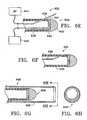
- a variation of the inventive deviceincludes a device that detects motion within tissue using Doppler measurements.
- the devicemay include a flexible member having a transducer assembly that is adapted to generate a source signal and receive a reflected signal.
- the inventive devicemay also comprise a hole-making assembly that is adapted to making collateral channels within tissue.
- the transducer assemblymay include an acoustic lens which enables the transmission and detection of a signal over a tip of the device.
- the hole-making assemblymay be an RF device and use portions of the tip of the device as RF electrodes, or the hole-making assembly may use ultrasound energy to make the hole.
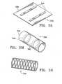
- a conduitcould, for example, have distal and proximal ends with a wall defining a lumen extending between the ends.
- the conduitcould have, for example, a porous wall permitting the exchange of gasses through the wall.
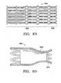
- the conduitmay, for example, be comprised of a material such as elastomers, polymers, metals, metal alloys, shape memory alloys, shape memory polymers, or any combination thereof.
- a variation of the inventionincludes an expandable conduit, either one that is self-expanding, or one that expands in diameter in relation to any applied radial, or axial force.
- the conduitmay be expanded into an opening of the natural airway upon the inflation of a balloon.
- a variation of the conduitmay include the use of flanges or anchors to facilitate placement of the device within an airway.
- Another variation of the conduitincludes placing a one-way valve within the conduit.
- Another variationincludes using a self cleaning mechanism within the conduit to clear accumulating debris.
- the inventive conduitmay be, for example, removable or permanent.
- another variation of the deviceincludes a means for inserting the conduit within a collateral channel.
- the conduitmay be constructed to allow for passage of gasses through its wall, for example, the conduit may have a wall consisting of a braid.
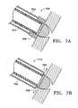
- a variation of the conduitmay be located through an opening in a wall of an airway and engage both an inside and outside of the wall.
- Another variation of the conduitincludes a distal end having a porous member and a proximal end having a grommet member which engages an opening in a wall of the natural airway.
- Yet another variation of the implantfor example, comprises an expandable conduit-like apparatus which could bridge an opening within a wall of a natural airway.
- Another variationincludes the conduit-like apparatus having a cutting portion exterior to the device wherein expansion of the device pierces the wall of the natural airway and creates a collateral channel.
- conduits of varying cross-sectional areasmay be placed in various sections of the lung to optimize the effect of the collateral channels.
- Another variation of the inventionincludes the application of a cyano-acrylate, fibrin or other bio-compatible adhesive to maintain the patency of a collateral channel.
- the adhesivemay be used with or without the conduit described above.
- the adhesivemay be deposited within the collateral channel to maintain patency of the channel or to create a cast implant of the channel.
- the inventive actfurther includes the act of delivering medications such as steroids which have been shown to inhibit the healing process, bronchodilators, or other such drugs which aid in breathing, fighting infection, or recovery from the procedure. The steroids inhibit inflammation and then promote the stabilization of the created channel.
- Another variation of the inventive processincludes promoting the flow of gasses through under-utilized parenchymal inter-conduits, or bypassing restricted airways. It is also contemplated that the gaseous flow may be altered by, for example, making separate inspiratory and expiratory paths. Also, relieving pressure on the external wall of a natural airway may be accomplished to assist the natural airway by maintaining patency during the expiration cycle of the lung. Yet another variation includes creating collateral channels parallel to existing airflow paths, or the existing airflow paths may be increased in cross-sectional area.
- the inventionfurther includes a device for altering gaseous flow in a diseased lung comprising a locator for locating a site for collateral ventilation of the lung, and optionally, a creating means for opening at least one collateral channel at the site.
- the deviceincludes a means for locating a blood vessel as described above.
- the devicemay use a mechanical, electrical, laser, ultrasonic, microwave, or chemical process for creating a collateral channel.
- Another variation of the deviceincludes a means for coagulating blood upon the entry of the device into a blood vessel.
- Yet another variation of the deviceincludes the means for locating and the means for creating are the same.
- the devicemay further include a means for simultaneously creating a plurality of collateral channels.
- Another variation of the implantincludes conduits constructed from materials that oppose the constriction of the natural airway over time during the expiration cycle of the lung. Yet another variation of the implant includes a device which expands as the pressure in the lung decreases during the expiration cycle.
- the inventionfurther includes a modified respiratory airway having an artificially created channel allowing gaseous communication between an exterior of the airway and an interior of the airway.
- the inventionmay include an endoscope or a bronchoscope configured to select sites and create collateral channels at those sites.
- An endoscope or a bronchoscopemay also be configured to deploy conduits within the collateral channels.
- Another variation of the inventionincludes sizing the device to fit within the working channel of a bronchoscope.
- the inventionalso includes methods for evaluating an individual having a diseased lung for a procedure to create collateral channels within an airway of the individual.
- the inventionfurther includes the method of determining the effectiveness of the procedure.
- the inventionfurther includes the act teaching any of the methods described above.
- the inventionfurther includes the method of sterilizing any of the devices or kits described above.
- Figure 1Ashows a natural airway 100 which eventually branches to a blood gas interface 102.
- Figure 1Billustrates an airway 100 and blood gas interface 102 in an individual having COPD.
- the obstructions 104impair the passage of gas between the airways 100 and the interface 102.
- Figure 1Cillustrates a portion of an emphysematous lung where the blood gas interface 102 expands due to the loss of the interface walls 106 which have deteriorated due to a bio-chemical breakdown of the walls 106.
- a constriction 108 of the airway 100It is generally understood that there is usually a combination of the phenomena depicted in figures 1A-1C. More usually, the states of the lung depicted in figures 1B and 1C are often found in the same lung.
- lung tissueis intended to include the tissue involved with gas exchange, including but not limited to, gas exchange membranes, alveolar walls, parenchyma and/or other such tissue.
- the collateral channelsallow fluid communication between an airway and lung tissue. Therefore, gaseous flow is improved within the lung by altering or redirecting the gaseous flow within the lung, or entirely within the lung.
- FIG. 1Dillustrate a schematic of a lung 118 to demonstrate a principle of the invention described herein.
- a collateral channel 112places lung tissue 116 in fluid communication with airways 100 allowing expired air to directly pass out of the airways 100.
- constricted airways 108may ordinarily prevent air from exiting the lung tissue 116.
- conduits 200may be placed in the collateral channels 112 to assist in maintaining the patency of the collateral channels 112. Therefore, it is not necessary to pierce the pleura to improve gaseous flow within the lungs.
- the inventionis not limited to the number of collateral channels which may be created, it is preferable that 1 or 2 channels are placed per lobe of the lung. For example, the preferred number of channels is 2-12 channels per individual patient.
- a variation of the inventive devicemay include an endoscope or a bronchoscope configured to locate a site for creating a collateral channel and create the collateral channel.
- Another variationincludes sizing the inventive device to fit within a working channel of an endoscope or a bronchoscope.
- any reference made to an endoscopeincludes the term bronchoscope.
- the inventionincludes assessing the degree of the collateral ventilation taking place in an area of a lung to select a site for creation of a collateral channel.
- the inventionmay include locating a site for creation of a collateral channel by visually examining an airway for dynamic collapse.
- One method of visual examinationincludes the use of a fiber optic line or camera which may be advanced into the lungs and through the airways.
- Also contemplated in the inventionis the addition of various agents to assist during imaging of the airways or lungs.
- a non-harmful gassuch as Xenon
- Another exampleincludes the use of inserting a fluid in the lungs to provide an improved sound transmission medium between the device and the tissue in variations of the invention using ultrasound, acoustic, or other imaging.
- Another variation of the inventionincludes methods and devices for triggering a collapse of the airway to determine the degree of collateral ventilation in the lung.
- One exampleincludes forcing a fluid, such as a gas, air, oxygen, etc., through the airway and into the air sacs.
- the pressureis reduced in the airway.
- One example of how pressure is reduced in the airwayincludes evacuating the air in a direction opposite to the air sacs. Constriction of the airway given a drop in pressure may be an indication of collateral ventilation of the lung in that region.
- FIG. 1Eillustrates a method and device 212 for causing collapse of the airway wall 100.
- the device 212includes a fluid delivery member 214 located at a distal end of the device 212.
- the fluid delivery member 214is configured to deliver a volume of fluid through the airway 100 and into an air sac (not shown).
- the device 212may also comprise a probe 216 configured to collect data within the lung.
- the probe 216may also simply consist of a channel that transmits signals outside of the lung.
- the fluid delivery member 214 and the probe 216may not be separate channels.
- the device 212may, but does not necessarily, have an occlusion member 218 designed to isolate a section of the airway 100 between the occlusion member 218 and the air sacs (not shown).
- the occlusion member 218, which forms a seal against the airway 100 walls,may provide a partially closed system allowing a more effective search for collateral ventilation between the air sacs (not shown.)
- the devicedelivers a burst of fluid, through the fluid delivery member 214 and subsequently uses the probe 216 to measure characteristics such as pressure, flow, or return volume to determine the degree of collateral ventilation.
- the term fluidis intended to include, air or a gas, such as oxygen, etc.
- the probe 216may fail to record any increase in pressure, volume, flow, or any other characteristic of the fluid at the site.
- Another variation of the inventionincludes using the fluid delivery member 214 to add or remove fluid distally to the occluded segment and using the probe 216 to monitor flow or pressure changes in the area. For example, if after adding/removing fluid the pressure in the occluded segment fails to build/drop, the assumption may be made that the gas is being collaterally vented through diseased air sacs.
- Figure 1Fillustrates another variation of the invention.
- the device 220comprises a separated probe 216 and gas delivery member 214.
- the fluid delivery member 214is configured to pass through a wall of the airway 100 so that fluid may be directly forced into, or pulled out of an air sac 102.
- Figure 1Gillustrates yet another variation of the invention.
- the device 222may have at least one fluid exchange passageway 224 .
- the device 222may force fluid into the airway 100 via the passageway 224 .
- fluidcan be pulled out via the passageway 224 , thus decreasing pressure distally to the device 222.
- the decrease in pressurepermits fluid to flow out of the airway 100 and away from the air sac (not shown).
- a variation of the inventionmay include an expandable member 218 , such as a balloon, to create a seal against the airway 100 walls. Forming a seal may provide a partially closed system to search for collateral ventilation between air sacs (not shown.)
- observation of a collapsing airway 100may indicate a desired site for creation of a collateral channel.
- Figure 2Aillustrates a blood vessel 110 on an outer wall of an airway 100 .
- the collateral channel 112 created using this inventionis located away from the vessel wall 110 .
- Such a positioning of the collateral channel 112eliminates the risk of rupturing the vessel 110 during formation of the collateral channel 112 .
- the term channelis intended to include an opening, cut, slit, tear, puncture, or any other conceivable artificially created opening.
- Figure 2Billustrates a first way of moving the nearby vessel.
- Figure 2Bshows the inflation of the airway 100 using a balloon 204 provided on a delivery device 202.
- the airway 100 and the vessel 110become delaminated thereby moving the vessel from the region just outside the exterior of the airway. Subsequent creation of a collateral channel using the inventive procedures will be less likely to hit the vessel.
- Figure 2Ddemonstrates another device 206 and method for delaminating an airway 100 from a vessel 110 .
- the two balloonsocclude the airway 100.
- the vessel 110 and the airway 100delaminate as the airway 100 separates from the vessel 110 . It may be desirable to make a channel while the airway is contracted as shown in figure 2E.
- Figure 2Fillustrates the insertion of a probe 210 into a wall of the airway 100.
- the probe 210is illustrated to be a singular probe, the delivery device 208 may be adapted to have multiple probes.
- the probe 210may detect the presence of blood such as when the probe is inserted into a vessel.
- the probe 210could be configured to puncture a wall of the airway 100 , and detect the presence of blood.
- the probe 210could pull a vacuum to facilitate entry of blood into the probe 210 .
- the probe 210may also use ultrasonic detection to determine the location of a vessel. For example, ultrasound may be used to determine changes in composition of the tissue beyond the airway wall for determination of the location of a vessel.
- a probe 210may, for example, use low frequency radio energy to induce heat at a point and determine the presence of a vessel by measuring a change in temperature due to the conduction away or removal of heat by the blood flowing within the vessel. Another variation is that the probe 210 could detect changes in impedance given a pre-arranged discharge of current through the bloodstream. If a probe 210 detects blood during its travel outside the airway, the user could select another spot for a collateral channel.
- Another variation of the inventionincludes methods and devices for determining whether a blood vessel is in proximity to a potential site. Making this determination prior to creating the channel is advantageous as the risk of puncturing a blood vessel is minimized.
- non-invasive imagingmay be used to locate blood vessels or to confirm the absence of a vessel at a site.
- Figure 2Gillustrates an example of this variation of the device 226 having a single sensor 228.
- the devicemay be, but is not necessarily, steerable and rotatable such that the sensor 228 can be placed in contact with any portion of the airway 100 wall.
- the devicemay be located to a site by the use of an endoscope.
- the device 226may also be stiff so that the sensor 228 may be placed in firm contact with a wall of the airway 100. It is important that the device does not 'wander' causing the creation of a collateral channel at a distance from the area originally searched. Such an occurrence may compromise a blood vessel (e.g., puncture, rupture, or otherwise open the blood vessel) even though the step of detecting the location indicated the absence of a blood vessel. In those cases, a stiffer wall provides added benefits.
- a blood vessele.g., puncture, rupture, or otherwise open the blood vessel
- Another variation of the inventionincludes inserting a fluid into the airway to provide a medium for the sensor 228 couple to the wall of the airway 100 to detect blood vessels.
- the devicemay use mucus found within the airway to directly couple the sensor 228 to the wall of the airway 100.
- Figure 2Hillustrates another variation of the inventive device 230 having a plurality of sensors 228 arranged in an array pattern. Although not shown, the array could extend around the circumference of the device 230.
- Figure 2Iillustrates yet another variation of the inventive device.
- the device 232comprises a plurality of sensors 228 arranged in a linear pattern. Although not shown, the pattern may also wind helically or in other patterns around the perimeter of the device 232.
- Figure 2Jillustrates another variation of the invention.
- the device 234comprises a sensor 228 encapsulated by an expandable member 236 e.g., a balloon.
- the expandable member 236may be filled with a fluid or other substance that couples the sensor 228 to an outer surface of the expandable member 236.
- the sensor 228may be rotatable within the expandable member 236, or the entire device 234 may be rotatable within the airway 100.
- Another variation of the device 234includes a mark 238 which provides a reference for orientation of the device 234 in the airway 100 .
- the mark 238is preferably remotely detectable and may be positioned on the expandable member 236.
- Another variation of the inventionincludes a means for marking the site.
- This variation of the deviceallows marking of the site after it is located. Accordingly, once marked, a previously selected site can be located without the need to re-examine the surrounding area for collateral ventilation, or the presence or absence of a blood vessel.
- the markingmay be accomplished by the deposit of a remotely detectable marker, dye, or ink.
- the markingmay comprise making a physical mark on the surface of the airway to designate the site.
- the markis detectable by such imaging methods as radiography, computer tomography (CT) imaging, ultrasound imaging, doppler imaging, acoustical detection, or thermal detection or locating.
- CTcomputer tomography
- the markmay be detectable by direct visualization such as the case when a fiber optic cable is used.
- Figure 2Killustrates an example of the device 240 having a sensor 228 to locate a site and a marking lumen 242 which may deposit an ink, dye, or other marker (not shown) on the site once located.
- the inventionmay include a user interface which provides feedback once an acceptable site is located. For example, once a site is located a visual or audible signal or image is transmitted to the user interface to alert the user of the location of a potential site.
- the signalcould be triggered once a blood vessel is located so that the site is selected in another location. In another example, the signal may trigger so long as a blood vessel is not located.
- FIGS 3A-3Idepict various ways of providing openings in the airway wall which may be used as collateral air passageways.
- Figure 3Aillustrates an airway 100 having a piercing member 300 and a dilation member 302 .
- the piercing member 300makes an incision (not shown) in the airway 100 wall.
- the piercing member 300is advanced into the wall so that a dilation member 300 can expand the incision to thereby provide a collateral channel.
- the dilation member 300is depicted as a balloon.
- One variation of the inventionincludes filling a balloon with a heated fluid as the balloon dilates the tissue to form the collateral channel. Use of a heated balloon allows the transfer of heat to the collateral channel for modifying the healing response.
- the dilation membermay be an expanding wedge (not shown) or other similar device.
- FIG. 3Bshows a cutting device 304 and an airway 100 having an opening 306 cut from a wall.
- a flap 308is cut from the wall and is attached to an outside or an inside wall of the airway 100.
- the flapmay be glued, using for instance, fibrin-based or cyano-acrylate-based glues or stapled to that wall.
- Figure 3Cillustrates a cutter 304 making an incision 310 in a wall of the airway 100.
- Figure 3Dillustrates one example of placing the walls of the airway 100 in tension and inserting a blunt instrument 314 into the incision.
- the delivery device 312is flexible and may be shaped to the contour of an airway 100 to provide support for the blunt instrument 314 so that the instrument 314 can advance into the incision.
- the delivery device 312is also used to deliver a blunt instrument 314 which expands the original incision.
- the blunt instrument 314may have a hooked configuration as needed.
- Figure 3Eshows the use of a balloon 320 to dilate a previously formed collateral channel in the airway wall 100. This procedure may be used variously with other mechanical, chemical, cryo-energy or RF based penetration systems to expand the size of that previously-formed opening.
- Figure 3Fillustrates a variation of the device 322 having an RF electrode 324 .
- This variation of the inventionuses RF energy to create a collateral channel.
- the device 322may be mono-polar or bi-polar.
- the RF energy throughout this inventionis similar to that of a typical RF cutting probe operating between the 300KHz-600KHz range.
- Figure 3G-3Iillustrates additional variations of devices of the present invention used to create collateral channels.
- the devicesmay use RF energy, either monopolar or bipolar, or the devices may use light, infrared heat, or any of the other methods describe herein.
- the device 328has an electrode 324 located on a side of the device. This variation of the device 328 automatically limits the depth of the collateral channel as the body of the device 328 remains against an airway 100 wall while the electrode 324 creates a channel.
- Figure 3H and 3Iillustrates another variation of a device 330 of the present invention having an electrode 324 located on a front face of the device.
- Figure 3Iillustrates a perspective view of the device 330 with an electrode on the front face 324.
- the device 330may either have an electrode 324 disposed on a front surface of the device 330 or the device may comprise a conductive material with an insulating layer 332 covering the device 330 and leaving an electrode surface 324 exposed.
- the size of the electrodemay be selected based upon the size of the desired collateral channel.
- the device of the present inventionmay also be configured to limit the depth of the collateral channel.
- the inventionmay include a shoulder or stop 326 to limit the depth of the collateral channel.
- Another exampleincludes graduated index markings on a proximal end of the device or on the distal end so long as they are remotely detectable.
- Also contemplatedis the use of RF impedance measuring. In this example, the use of RF impedance may be used to determine when the device leaves the wall of the airway and enters the air sac or less dense lung tissue.
- the inventionalso includes creating a collateral channel by making a single or a series of incisions in an airway wall then folding back the cut tissue through the collateral channel.
- This procedureallows the surface epithelium which was previously on the inside of the airway wall to cover the walls of the newly formed collateral channel.
- promoting growth of the epithelium over the walls of the collateral channelprovides a beneficial healing response.
- the incisionmay be created by the use of heat or a mechanical surface.
- Figure 3Jillustrates a section of an airway 100 having several incisions 356 forming a number of sections 358 of airway wall tissue the airway 100.
- Figure 3Killustrates the sections or flaps 358 of the airway wall folded through the collateral channel 112.
- incisions 358may be made to form any number of sections 358 of airway wall tissue as desired.
- a plus-shaped incisionwould result in four sections of tissue that may be folded through a channel.
- the sections 358may be affixed with a suture material, an adhesive, or the sections 358 may simply be inserted into surrounding tissue to remain folded through the collateral channel 112.
- Another variation of the deviceincludes safety features such as probes to determine the presence of blood. If a probe indicates that a blood vessel is contacted or penetrated, a signal is sent which prevents the channel making device from causing further harm to the vessel. Such a feature minimizes the risk of inadvertently puncturing a blood vessel within the lungs.
- the present inventionincludes the use of a device which is able to detect the presence or absence of a blood vessel by placing a front portion of the device in contact with tissue.
- One variation of the inventionincludes the use of Doppler ultrasound to detect the presence of blood vessels within tissue. It is known that sound waves at ultrasonic frequencies travel through tissue and reflect off of objects where density gradients exist. In which case the reflected signal and the transmitted signal will have the same frequency. Alternatively, in the case where the signal is reflected from the blood cells moving through a blood vessel, the reflected signal will have a shift in frequency from the transmitted signal. This shift is known as a Doppler shift. Furthermore, the frequency of the signals may be changed from ultrasonic to a frequency that is detectable within the range of human hearing.
- the ultrasound Doppleroperates at any frequency in the ultrasound range but preferably between 2Mhz-30Mhz. It is generally known that higher frequencies provide better the resolution while lower frequencies offer better penetration of tissue. In the present invention, because location of blood vessels does not require actual imaging, there may be a balance obtained between the need for resolution and for penetration of tissue. Accordingly, an intermediate frequency may be used (e.g., around 8 Mhz).
- FIG. 6Aillustrates a variation of a device 600 adapted to determine the presence of blood vessels as previously mentioned.
- the device 600includes a flexible elongate member 604 having a transducer assembly 606 , at least a portion of which is located adjacent to a distal end of the elongate member 604.
- the elongate member 604is illustrated as having a lumen, the elongate member 604 may also be selected to be solid, or the elongate member 604 may have a support member (not shown) such as a braid to increase the strength and/or maneuverability of the device.
- the transducer assembly 606is adapted to generate a source signal and receive a reflected signal. It may use a single transducer or multiple transducers. For example, at least a first transducer may be used to generate a signal and at least a second transducer may be used to receive the signal.
- the transducer or transducers usemay comprise a piezo-ceramic crystal.
- a single-crystal piezo (SCP)is preferred, but the invention does not exclude the use of other types of ferroelectric material such as poly-crystalline ceramic piezos, polymer piezos, or polymer composites.
- the substratetypically made from piezoelectric single crystals (SCP) or ceramics such as PZT, PLZT, PMN, PMN-PT
- the crystalmay be a multi layer composite of a ceramic piezoelectric material. Piezoelectric polymers such as PVDF may also be used.
- the transducer or transducers usedmay be ceramic pieces coated with a conductive coating, such as gold.
- conductive coatingsinclude sputtered metal, metals, or alloys, such as a member of the Platinum Group of the Periodic Table (Ru, Rh, Pd, Re, Os, Ir, and Pt) or gold. Titanium (Ti) is also especially suitable.
- the transducermay befurther coated with a biocompatible layer such as Parylene or Parylene C.. The transducer is then bonded on the lens. A coupling such as a biocompatible epoxy may be used to bond the transducer to the lens.
- the transducer assembly 606communicates with an analyzing device 602 adapted to recognize the reflected signal or measure the Doppler shift between the signals. As mentioned above, the source signal may be reflected by changes in density between tissue.
- the reflected signalwill have the same frequency as the transmitted signal.
- the reflected signalhas a different frequency than that of the source signal.
- This Doppler effectpermits determination of the presence or absence of a blood vessel within tissue.
- the analyzing device 602may alternatively be incorporated into the device 600 .
- the transducer assembly of the inventionis intended to include any transducer assembly that allows for the observation of Doppler effect, e.g., ultrasound, light, sound etc.
- the device 600 illustrated in figure 6Aincludes a transducer assembly 606 comprising an ultrasound transducer 608 and an acoustic lens 610 that is adapted to refract and disperse a source signal over an outer surface of the lens 610 .
- the lens 610is designed such that it interferes and redirects the signals in a desired direction.
- the lens 610may be comprised of materials such as dimethyl pentene (plastic-TPX), aluminum, carbon aerogel, polycarbonate (e.g., lexan), polystyrene, etc. It also may be desirable to place an epoxy between the lens 610 and the transducer 608 . Preferably, the epoxy is thin and applied without air gaps or pockets.
- the density/hardness of the epoxyshould provide for transmission of the signal while minimizing any effect or change to the source signal.
- the configuration of the transducer assembly 606permits the lens 610 to disperse a signal over a substantial portion of the outer surface of the lens 610.
- the lens 610also is adapted to refract a reflected signal towards the transducer 608. Accordingly, given the above described configuration, the device 600 of figure 6A will be able to detect vessels with any part of the lens 610 that contacts tissue (as illustrated by the line 612-612.)
- the lens 610is illustrated as being hemispherical, as described below, the lens 610 may have other shapes as well.
- Figure 6Billustrates another variation of the device 614 having a hemispherical shaped ultrasound transducer 618 affixed to an end of a flexible elongate member 616.
- the transducer 618communicates with an analyzing device (not shown) to measure the Doppler effect to determine the location of a blood vessel.
- Figure 6Cillustrates another variation of the device 620 including a transducer assembly 622, at least a portion of which is located adjacent to a distal end of the elongate member 628.
- the transducer assembly 622includes a flat ultrasound transducer 626, and a cone or wedge-like acoustic mirror 624.
- the mirror 624is adapted to reflect the signal over an area 360° around the device. The angle ⁇ of the mirror may be varied to optimally direct the signal as needed.
- Figure 6Dillustrates a variation of a device 630 of the present invention further comprising a joint 632 to articulate an end of the device either to make sufficient contact with an area of tissue to be inspected for the presence of a blood vessel, or to navigate within the body to access the area to be inspected.
- the variations of the invention described hereinmay also be adapted to use ultrasound energy, for example, high energy ultrasound, to produce openings in or marks on tissue.
- ultrasound energyfor example, high energy ultrasound
- the transducer assembly and acoustic lensalso functions as a hole-making or site marking device.
- use of ultrasound in a low power operationpermits the detection of a blood vessel and location of a site for a collateral channel.
- Using the same device and switching the operation of the device to a high power ultrasoundpermits the use of the ultrasound to create a collateral channel.
- Figure 6Eillustrates a variation of a device 632 comprising a transducer assembly 634 connected to a flexible elongate member 636 .
- the transducer assembly 634comprises a first transducer 641, a second transducer 642, and an acoustic lens 640.
- one transducermay transmit a signal while the other receives a signal.
- both transducers 641, 642may simultaneously transmit and receive signals. It is intended that any combination of using the transducers to send and receive signals is contemplated.
- the device 632also includes a hole-making assembly 638 for creating a channel in tissue.
- Figure 6Eillustrates the hole-making assembly 638 as an RF wire-like member. As illustrated, the device 632 is connected an RF generator 644 as well as an analyzing device 646 which is adapted to measure the Doppler shift between the generated and reflected signals.
- Figure 6Fillustrates the device 632 of Figure 6E where the hole-making assembly 638 is retracted within the device 632 , in this case within the elongated member 636 .
- Figure 6Gillustrates another variation of a device 648 where a hole-making assembly 650 is exterior to a transducer assembly 606 .
- the hole-making assembly 650may be either an RF device or a mechanical device that simply cuts the tissue.
- the hole making assembly 650can be a hypotube placed over the transducer assembly 606.
- the transducer assembly 606may be moveable within the hole-making assembly 650 , or the hole-making assembly 650 may be moveable over the transducer assembly 606 . In either case, the transducer assembly 606 may be advanced out of the hole-making assembly 650 to determine the presence of a blood vessel.
- the transducer assembly 606may be withdrawn into the hole-making assembly 650 allowing the hole-making assembly 650 to create a channel in the tissue either by mechanically cutting the tissue, or by using RF energy to create the channel.
- Figure 6Hillustrates a view taken along the line 6H in Figure 6G.
- Figure 6Iillustrates another version of a device 652 of the present invention wherein the device has a transducer assembly 654 with an opening 658 through which a hole-making assembly 656 may extend.
- Figure 6Jillustrates the hole-making assembly 656 extended through the transducer assembly 654.
- the hole-making assembly 656may comprise RF electrodes or needle-like members which puncture the tissue to create the channels.
- Figure 6Killustrates a variation of a device 666 of the present invention where a tip 660 of the device has a conductive portion allowing the tip to serve as both an acoustic lens and an RF electrode.
- the tip 660is connected to an RF generator 644 for creating channels within tissue and a transducer 662 is placed in communication with an analyzing device 646 that is adapted to measure the Doppler shift between generated and reflected signals.
- the tip 660is separated from the transducer 662 , but both the tip 660 and transducer 662 are in acoustic communication through the use of a separation medium 664 .
- the separation medium 664transmits signals between the tip 660 and the transducer 662 .
- the spacing of the transducer 662 from the tip 660serves to prevent heat or RF energy from damaging the transducer 662 . It is intended that the spacing between the transducer 662 and tip 662 shown in the figures is for illustration purposes only. Accordingly, the spacing may vary as needed.
- the separation mediummust have acceptable ultrasound transmission properties and may also serve to provide additional thermal insulation as well. For example, an epoxy may be used for the separation medium.
- Figure 6Lillustrates a variation of a device 680 of the present invention wherein the transducer assembly 670 comprises a tip 672 , an ultrasound coupling medium 674 , a transducer 676 , and an extension member 678 .
- the tip 672 of the deviceserves as an acoustic lens and also has conductive areas (not shown) which serve as RF electrodes.
- the tip 672may extend from the device 680 and separate from the transducer 676. Separation of the tip 672 protects the transducer 676 from heat or RF energy as the tip 672 creates a channel in tissue.
- the extension member 678may serve as a conductor to connect the tip 672 to an RF energy supply (not shown).
- the tip 672 of the device 680When the tip 672 of the device 680 is being used in an ultrasound mode, the tip 672 may be coupled to the transducer 676 via the use of an ultrasound coupling medium 674. Any standard type of ultrasound gel material may be used, also highly formable silicone may be used. It is desirable to use a fluid boundary layer (such as the gel) which may be permanent or temporary. In those cases where the boundary layer is temporary, subsequent applications of the boundary layer may be necessary.
- Figure 6Nillustrates another variation of a device 682 of the present invention having a tip 684 and transducer 686 that are separable from each other.
- the tip 684may include conductive areas and serve as both an RF electrode (not shown) as well as an acoustic lens.
- the tip 684may be separable from the transducer 686 when creating a channel to protect the transducer 686 from heat or RF energy.
- the tip 684may be placed in contact with the transducer 686 for operation in an ultrasound mode, or the device 682 may contain a separation medium 688 which permits acoustic coupling of the transducer 686 with the tip 684 when separated.
- Figures 6P-6Uillustrate variations of RF electrode tip 690 configurations for use with the present invention.
- the electrodesmay be placed around a circumference of a tip, longitudinal along a tip, spirally along a tip, or a combination thereof.
- the electrodes 692, 694may be used with a device having an acoustic lens or the electrodes may be employed solely as an RF hole-making device. While the variations illustrated in Figures 6P-6U show bipolar RF devices, the invention may also use a single electrode (monopolar.)
- the tip 690may contain a first electrode 692 separated from a second electrode 694 by an electrical insulator 696 (e.g., ceramic, or plastic insulator).
- an electrical insulator 696e.g., ceramic, or plastic insulator
- Figure 6Villustrates a coaxial variation of a bi-polar RF tip having a first electrode 692, a second electrode 694, and an insulator 696.
- Figure 6W and 6Xillustrates additional variations of the lens of the present invention.
- Figure 6Willustrates a device 724 with an acoustic lens 726 having an oblate spheroid shape.
- Figure 6Xillustrates a device 728 with an acoustic lens 730 having a prolate spheroid shape.
- Figure 6Yillustrates a device 732 having a conical-shaped acoustic lens 734 .
- These variationsare only intended to illustrate variations of the lens. It is contemplated that the shape of a lens may not follow a mathematical description such as conical, prolate, oblate or hemispherical.
- the design of the shaperelates to the distribution pattern of the signal over the lens. The shapes can affect the distribution pattern by making it wider or narrower as needed. In any case, the lens is of a shape that provides coverage over the front face of the device.
- Figure 7Aillustrates a variation of the invention where a device 700 includes a heat-sink member 702 .
- the heat-sink member 702may preserve surround tissue during creation of the collateral channel.
- the heat-sink member 702may be a section of conductive material or a balloon.
- the heat-sink member 702may be in fluid communication with a lumen 704 that provides a fluid, such as saline, that conducts heat away from the area surrounding the channel.
- Figure 7Billustrates another variation of a device 710 having a fluid delivery assembly 706 which assists in preserving surrounding tissue while a channel is being created.
- the fluid delivery assembly 706may spray, mist, or otherwise apply fluid 708 to the area surrounding the channel.
- cooled salinemay be applied to the area to prevent excessive heating of the target area.
- FIG. 7Cillustrates a variation of an RF electrode 712 for use with the present invention.
- the electrode 712may be a protrusion extending from a conductive member 716 that is covered with an insulating material 714.
- the electrode 716limits the depth of the channel due to the amount of material extending from the conductive member 716 .
- the conductive member 716may be connected to a source of RF energy (not shown) or may use another heating element (not shown).
- Figure 7Dillustrates another variation of an electrode configuration.
- the electrodecomprises a spherical member 718 extending from an elongate member 722.
- the electrode 718is retractable through the elongate member 722 by use of an actuator 720.
- the actuator 720may be conductive and connected to a source of RF energy to conduct energy through the electrode 718. Again, the design of the electrode 718 limits the depth of penetration of the electrode 718 while creating a channel in tissue.
- the electrodes described hereinmay also be used in conjunction with a device having a Doppler arrangement.
- a variation of the inventioncontemplates the delivery of drugs or medicines to the area of the collateral opening.
- a fibrin, cyano-acrylate, or any other bio-compatible adhesiveto maintain the patency of the opening.
- the adhesivecould be deposited within the collateral channel to maintain patency of the channel or to create a cast implant of the channel.
- the adhesivecould also coat the channel, or glue a flap to the wall of the airway.
- the use of a bioabsorbable materialmay promote the growth of epithelium on the walls of the conduit. For example, covering the walls of a channel with small intestine submucosa, or other bioabsorbable material, may promote epithelium growth with the bioabsorbable material eventually being absorbed into the body.
- Figure 4illustrates a variation of a device 400 having the ability to create multiple openings within the walls of the natural airway 100.
- the holesmay be created by dilation, cutting, electrical energy, microwave energy, ultrasonic energy, laser, chemical, or any process as mentioned above.
- This device 400may also be used to deploy multiple probes to determine the location of a blood vessel (not shown) using one of the procedures mentioned above.
- FIG 5Aillustrates an implant or conduit 500 placed within a natural airway 100.
- the airway 100has a portion of its wall removed, thereby providing a collateral opening 112 within the airway 100 .
- the implant 500typically has a porous structure which allows gasses to pass between the airway and the channels 112 and into the lung. Moreover, the structure of the insert 500 also maintains patency of the airway 100 and the channel 112.
- a conduit described hereinmay comprise a barrier layer which is impermeable to tissue. This aspect of the invention prevents tissue in-growth from occluding the channel.
- the barrier layermay extend between the ends of the body or the barrier layer may extend over a single portion or discrete portions of the body of the conduit.
- Figure 5Billustrates an conduit 500 having an expandable structure within an airway 100 .
- the conduit 500has a porous wall that allows the passage of gasses through the wall.
- the conduit 500is delivered via a delivery device 502 which may also contain an expandable member (not shown) which expands the conduit 500.
- the conduitmay have piercing members 504 attached on an outer surface which enable the conduit 500 to create an incision within the airway 100.
- Figure 5Cillustrates the conduit 500 after being expanded by an expandable member 506, e.g. a balloon device, an expandable mechanical basket, or an expandable wedge.
- an expandable member 506e.g. a balloon device, an expandable mechanical basket, or an expandable wedge.
- the conduit 500expands through the walls of the airway 100 at sections 508.
- the conduit 500is lodged within the walls of the airway 100.
- Figure 5Dillustrates a grommet-like insert 503 where the lumen of the insert 503 extends longitudinally through the collateral channel:
- an expanding member 501e.g., a balloon, an expanding mechanical basket, or the like is used to secure the conduit 503 within the collateral channel.
- conduitshaving a length to diameter ratio approximately 1:1. However, this ratio may be varied as required.
- the cross-section of an implantmay be circular, oval, rectangular, eliptical, or any other multifaceted or curved shape as required.
- the cross-sectional area of an implant 500may be between 0.196 mm 2 to 254 mm 2 .
- the conduitmay also be any device capable of maintaining a patent opening, e.g., a plug, that is temporarily used as a conduit and then removed after the channel has healed in an open position.
- a plugmay be a solid plug without an opening that is either bio-absorbable or removable. In such a case, the plug may be placed within an opening in tissue and allow the tissue to heal forming a collateral channel with the plug being ultimately absorbed into the body or removed from the body.
- the conduit 510comprises a cone 514 with a grommet 512 for attachment to a wall of the airway 100.
- the cone 514may be porous or have other openings 516 to facilitate the passage of gas through the collateral channel. In the event that the distal opening of the cone become occluded, the porous cone permits the continued exchange of gasses between the collateral channel and the natural airway.
- the conduit 518may be configured in a 't-shape' with a portion 520 of the conduit extending through the collateral channel.
- the conduit 518may be constructed to have a porous wall to allow gas exchange through the wall.
- the conduitmay be configured in a variety of shapes so long as a portion of the conduit extends through the collateral channel.
- the portionmay be formed into a particular shape, such as the 't-shape' described above, or, the portion may be hinged so that it may be deployed within the channel. In such a case, a portion of a wall of the conduit may have a hinge allowing the wall of the conduit to swivel into a channel.
- conduit 522is constructed with a geometry that reduces the chance that the conduit 522 will migrate within the airway 100 .
- Figure 5Hillustrates an example of a conduit 524 having an asymmetrical profile.
- the conduit 524may have a flange 526 at either or both ends of the body 528 .
- the flange 526may have a cone-like profile to facilitate placement within an airway.
- the asymmetrical profile of the conduit 524assists in preventing obstruction of the airway.
- Figure 5Killustrate a variation of the conduit 530 having a self-cleaning mechanism.
- the self cleaning mechanismis a floating ball bearing 532.
- the ends of the conduit 530have a reduced diameter 534 which prevents the bearing 532 from escaping.
- the bearing 532moves about the conduit 530 clearing it of debris.
- the shape of the bearing 532 and the size and shape of the reduced diameter 534may be varied to optimize the self-cleaning effect of the device.
- Figure 5L and 5Millustrate another variations of a self-expanding conduit 536.
- the conduit 536may be constructed from a flat material 538 having a spring or springs 540 .
- the conduit 536is formed by rolling the assembly.
- the spring 540provides an expanding force against the material 538 .
- the conduit 536may also be constructed so that the flat material 538 is resilient thus eliminating the need for springs 540.
- Figure 5Nillustrates another variation of an expandable conduit 542 constructed from a braided material.
- the conduit 542may be constructed so that the diameter is dependent upon the length of the device 542. For example, the diameter of the device 542 may decrease as the length is stretched, and the diameter may increase as the length of the device 542 is compressed. Such a construction being similar to a 'finger cuff' toy.
- Figures 5O-5Qillustrate another variation of a grommet-type conduit.
- Figure 5Oillustrates a conduit 544 having expandable ends 546.
- the ends 546 of the device 544may flare outwards as illustrated in figure 5P.
- Figure 5Oillustrates another variation of the device 544 in which the ends 546 compress in length to expand in diameter.
- Figures 5R and 5Sillustrate variations of a conduit having an anchor.
- the conduit 548has an anchor 550 at a distal end of a hollow plug 540 .
- the anchor 550may be tapered to facilitate entry into the airway 100 wall or may have another design as required.
- the anchor 550also contains ventilation openings 552 to facilitate gas exchange through the device.
- Figure 5Sillustrates another variation of the device.
- Figure 5Tillustrates a variation of a conduit 561 having flanges 563 at either end to assist in placement of the conduit within an airway wall (not shown).
- the ends of the conduit 565may be tapered to ease placement through a collateral channel.
- the conduithas an opening 565 to facilitate passage of air.
- the conduit 561may be constructed from a biocompatible material, such as stainless steel, or plastic.
- Figure 5Uillustrates a variation of the invention having multiple openings for gas flow.
- the conduit 560has a first hollow end 564 which can extend through a wall of the airway 100 and a second hollow end 566 which can remain parallel to the airway 100 .
- This examplealso includes an opening 562 which allows gas to flow through the airway 100 .
- Figure 5Villustrates a variation of the device having a one-way valve 570 .
- the valve 570allows the conduit 568 to permit exhaust of the air sac but prevents the conduit 568 from serving as another entrance of gas to the air-sac.
- the valve 570may be placed at ends of the conduit or within a lumen of the conduit.
- the valve 570may also be used as bacterial in-flow protection for the lungs.
- Figure 5Willustrates another variation of a conduit 572.
- the conduit 572may be a sponge material, or constructed of an open cell material 574, which allows air flow through the material.
- the conduit 572may have lumens 576 which allow flow through the conduit 572.
- the conduit materialmay be selected such that it expands as it absorbs moisture.
- the sponge material/open cell materialmay be bio-absorbable to allow for temporary placement of the conduit 572.
- Figures 8A-8Fillustrate another variation of a conduit 800 of the present invention.
- the conduit 800has a center section 802 having extension members 804 located at either end of the center section 802 .
- the center section 802 illustratedis tubular but may be of any other shape as needed for the particular application.
- the conduit of the inventionhas a passageway extending between the ends of the conduit suited for the passage of air.
- the variation of the conduit 800 illustrated in Figure 8Ahas a center section 802 comprising a mesh formed from a plurality of ribs 806.
- Figure 8A and 8Billustrate the conduit 800 in a reduced profile while Figure 8C and 8D illustrate the conduit 800 in an expanded profile after expansion of the center section 802 of the conduit 800.
- each free end 808 of each extension member 804is unattached to the center section 802 and is bendable about the respective end of the center section 802 to which it is attached. Accordingly, once a conduit 800 is placed within a collateral channel (not shown), the extension members 804 are bent about the end of the center section 802 and form a cuff or grommet which assists in keeping the conduit 800 within a collateral channel. Accordingly, the cross section and number of extension members 804 located about either end of the conduit 800 may be selected as necessary to assist in placement and securing of the conduit 800 within a channel.
- the conduits described hereinmay have a fluid-tight covering, as discussed below, about the center section, the extension members, or the entire conduit. Also, the conduit may be designed to limit a length of the center section to less than twice the square root of a cross sectional area of the center section when the center section is in the expanded profile.
- Figure 8G-8Iillustrates another variation of a conduit 812 for use with the invention.
- the conduit 812is formed from a rolled sheet of material 810.
- the rolled sheet 810may be heat treated to preserve the shape of the conduit 812 or the sheet 810 may simply be rolled to form the conduit 812 .
- the sheet of material 810comprises a shape-memory alloy, it is desirable to process the material 810 so that it exhibits super-elastic properties at or above body temperature.
- Figure 8Gillustrates a variation of extension members 820 for use with a conduit (not shown) of the present invention.
- the extension members 820have an attachment 822 between adjacent extension members 820 .
- Figure 8Hillustrates the extension members 820 as the conduit (not shown) is expanded and the extension members 820 are bent on the conduit.
- the attachment 822assists in preventing the extension members 820 from deviating from a preferred position.
- the conduit 826may have cut or weakened sections 824 to facilitate expansion of the conduit 826 and bending of the extension members in a desired manner (as shown by the section of 828).
- Figures 8J-8Killustrate various additional cross sectional designs of conduits.
- Figure 8Jillustrates a possible conduit design 830 having extension members 834 attached to a center section 832 .
- Figures 8K and 8Lillustrate additional variations of conduit designs.
- the extension members 840, 846 and center sections 838, 844are designed to form a diamond pattern upon expansion of the conduit.
- Figure 8Kfurther illustrates a variation of an extension member 840 having an opening 841 to facilitate tissue in-growth and thereby secures placement of the conduit.
- Figure 8Millustrates an expanded conduit 848 having the diamond pattern referred to above.
- the conduit 848also contains a fluid-tight barrier 851 on the center section 850 of the conduit 848. Although not illustrated, fluid-tight barrier may be placed throughout a conduit.
- Another feature of the variation of Figure 8Mis that the extension members have a diamond pattern construction, this construction assists in maintaining alignment of the extension members allowing for a preferred aligned expansion of the extension members.
- Figures 8N-8Oillustrate another variation of a conduit 860 of the present invention.
- the conduit design 854may have extension members 856 at only one end of the conduit 860 .
- the center section of the conduitmay comprise a body portion 858.
- the conduit 860may have a covering about a portion of the conduit 860 . The covering may extend throughout the length of the conduit 860 or it may be limited to a portion of the conduit 860 .
- the conduit 860when expanded, the conduit 860 may form a reduced area 858 near the extension members 856 .
- the conduit cross section 854may be designed such that the a diamond pattern is formed upon expansion of the conduit 860 , as illustrated in Figure 8O.
- Figure 8Pillustrates a sheet of material 810 having extension members 814 extending from either end of the sheet 810 .
- a conduitmay be formed from a sheet having openings within the center section of the sheet.
- Figure 8Qillustrates the conduit 812 where the rolled sheet 810 comprises a center section 818 of the conduit 812 and the extension members 814 from either end of the center section 818 .
- the sheet 810may be overlapped for a reduced profile and expanded into an expanded profile.
- Figure 8Rillustrates a free end 816 of each extension member 814 as having been bent away from a central axis of the conduit 812.
- the extension members 814 of the conduit 812may be bent away from a central axis of the conduit 812 up to 180° with respect to the central axis.
- the cross section and number of extension members 814 located about either end of the conduit 810may be selected as necessary to assist in placement and securing of the conduit 810 within a channel.
- the conduit 812 of figure 8Qcomprises a non-shape memory alloy the conduit 812 will be actively mechanically expanded.
- the conduit 812may be pre-formed to assume a deployed shape which includes a grommet formed by extension members 814 and an expanded center section 818, such as the shape illustrated in Figure 8R.
- the super-elastic conduit 812may be restrained or even rolled into the shape illustrated in Figure 8Q. Because the conduit 812 is formed of a super-elastic material, no plastic deformation occurs. When the super-elastic conduit 812 is then placed within a collateral channel, the conduit 812 may naturally resume its pre-formed, deployed shape.
- Figure 8Sillustrates another variation of a conduit 862 having a first portion 864 and a second portion 866 and a passageway 868 extending therethrough.
- the first portion 864may be a conduit design as described herein.
- the first portion 864is configured to secure the conduit 862 to the airway wall 100.
- the first portion 864may or may not have a center that is expandable.
- the walls of the first portion 864may be fluid-tight (either through design, or a fluid tight covering) to prevent tissue in-growth through the collateral channel:
- the first portion 864may be partially fluid-tight to facilitate tissue in-growth to improve retention of the conduit 862 to the airway wall 100.
- the first portion 864should be designed to minimize tissue in-growth within the channel to prevent substantial interference with airflow through the conduit 864.
- the walls of the second portion 866 of the conduitmay or may not be fluid-tight. If the second portion 866 is not fluid-tight, the larger area provides for improved airflow from lung tissue through the passageway 868 and into the airway.
- the second portion 866may also be designed to be partially fluid-tight to encourage airflow through the conduit 862 but reduce the probability of blockage of the conduit 862 .
- Figures 8T-8Uillustrate another variation of a conduit 870.
- the conduit 870may be formed from a tube that is slit to form extension members at a first portion 872 and second portion 876 with a center section 874 between the portions.
- the conduit 870may be expanded as shown in Figure 8U such that the first 872 and second 876 portions maintain the center portion 874 in a collateral channel in an airway wall.
- the center section 874may or may not be expandable.
- Figure 8Uillustrates the second portion 876 of the conduit 870 to expand in its center
- the conduit 870may be designed in other configuration as well (e.g., expanded to have a larger diameter at an end opposite to the center section 874.)
- a central aspect of this designis that the second portion 870 provides a large area in the lung tissue to permit a larger volume of air to pass from the lung tissue into the conduit 870.
- This designhas an added benefit as the second portion 876 cannot be easily blocked by flaps of parenchyma tissue.
- a simple variation of the conduit 870may be constructed from a metal tube, such as 316 stainless steel, titanium, titanium alloy, nitinol, etc.
- the conduitmay be formed from a rigid or elastomeric material.
- the conduits described hereinmay be comprised of a metallic material (e.g., stainless steel), a shape memory alloy, a super-elastic alloy (e.g., a NiTi alloy), a shape memory polymer, a polymeric material or a combination thereof.
- the conduitmay be designed such that its natural state is an expanded state and it is restrained into a reduced profile, or, the conduit may be expanded into its expanded state by a variety of devices (e.g., a balloon catheter.)
- the conduit described hereinmay be manufactured by a variety of manufacturing processes including but not limited to laser cutting, chemical etching, punching, stamping, etc.
- the conduits described hereinmay be coated with an elastomer, e.g., silicone, polyurethane, etc.
- the coatingsmay be applied, for example, by either dip coating, molding, or liquid injection molding (for silicone).
- the coatingmay be a tube of a material and the tube is placed either over and/or within the conduit.
- the coating(s)may then be bonded, crimp, heated, melted, or shrink fit.
- the coatingsmay also placed on the conduit by either solvent swelling applications or by an extrusion process.
- a coating ofmay be applied by either wrapping a sheet of PTFE about and/or within the conduit, or by placing a tube about and/or within the conduit and securing the tubes.
- the number of and cross sectional area of the extension members on a conduitmay be selected as needed for the particular application.
- the extension membersmay be bent such that they anchor into the tissue thereby securing placement of the conduit.
- the extension members or the center sectionmay contain barbs or other similar configurations to better adhere to the tissue.
- the orientation of the extension membersmay vary as well.
- the extension membersmay be configured to be radially expanding from the center section, or they may be angled with respect to a central axis of the conduit.
- Another variation of the inventionincludes a radioactive conduit which inhibits or prevents the growth of tissue within the conduit.
- conduits of the current inventionhave been described to contain expandable center sections, the invention is not necessarily limited as such. Instead, the design of the conduit may require extension members on the ends of a conduit with a non-expandable center section.
- Figures 9A-9Dillustrate a conduit 900 of the present invention.
- the deployment of the conduit 900is intended to show an example of a possible means of deployment only.
- the inventive conduitmay be delivered at an angle via an articulating or jointed device, the conduit may be delivered on a device that is adapted to locate and create the collateral channel, or the conduit may be delivered on a device having other features as needed for the particular application.
- Figure 9Aillustrates the conduit 900 being delivered to a collateral channel in an airway wall 114 via a delivery device (e.g., a balloon catheter 902. )
- the conduit 900may be attached to the delivery device 902 using the natural resiliency of the conduit 900 .
- the conduit 900restrained in a reduced profile and may be removably affixed to the delivery device 902 using an adhesive, or a removable sleeve such as a heat shrink tube.
- the balloon catheter 902has several balloons including a distal balloon 904, a proximal balloon 906, and a center balloon (not illustrated in Figure 9A).
- Figure 9Billustrates the inflation of the distal 904 and proximal 906 balloons to situate the extension members 908. Accordingly, the extension members 908 for a flange or collet about the airway wall 114 .
- the balloons 904 , 906may be inflated simultaneously, or in a desired sequence. In any case, deployment of the balloons 904, 906 may serve to center the conduit 900 in the collateral channel.
- Figure 9Cillustrates inflation of the center balloon 912 which causes expansion of the center section 910 of the conduit 900. If the conduit 900 is affixed to the delivery device 902, expansion of the center balloon 912 causes release of the conduit 900 by release of the adhesive or breaking of the heat shrink tubing (not shown).
- the means of attachmentmay be bioabsorbable and remain in the body, or may remain affixed to the delivery device 902 and is removed with removal of the delivery device 902.
- Figure 9Dillustrates the conduit 900 affixed to the airway wall 114 after the delivery device 902 is removed from the site.
- FIG. 9E and 9Fillustrate possible ways to manipulate a conduit 914 for placement in an airway wall 114 using a delivery device 916.
- Figure 9Eillustrates deployment of a delivery device 916 to place a conduit 914 within an opening in an airway wall 114.
- the conduit 914may be placed over a balloon 918 (or other expandable section) of the delivery device 916.
- Figure 9Fillustrates deployment of the balloon 918 to place and expand the conduit 914.
- a balloon 918serves several functions. The balloon 918 first expands and starts bending the extension members 920. The balloon 918 continues to center the conduit 914 on the tissue and simultaneously begins to expand the conduit 914 and secures the conduit to the tissue.
- FIGS 9G and 9Hillustrate additional variations of deployment devices.
- the deployment devices 922, 926contain hourglass-shaped balloons 924, 928 .
- the hour glass-shaped balloons 924, 928contain an interior profile 923 .
- the conduitis placed on the balloon 924 , 928 .
- the balloon 924, 928expands, the conduit expansion matches the interior profile 923 of the balloon 924, 928 .
- the hour glass-shaped balloon 924, 928may be used to set the angle and orientation of the expandable members of a conduit as well as the expansion of a center section of the conduit.
- Figure 9Iillustrates another variation of an hour glass shaped balloon delivery device 930.
- This variation of the hour glass shaped balloon 932is designed to expand extension members (not shown) of a conduit (not shown) at a particular angle 934.
- the orientation of the balloon 932may be designed as needed to impart the desired angle to the extension members of the conduit.
- the balloons described hereinmay be constructed polyethylene terephthalate (PET) or any other material which is used in the construction of balloon catheters.
- the inventionfurther includes methods of evaluating individuals having a diseased lung to assess inclusion of the individual for the procedure.
- the methodcomprises the steps of performing pulmonary function tests on the individual.
- the pulmonary function testsmay obtain such values as FEV (forced expiratory volume), FVC (forced vital capacity), FEF 25%-75% (forced expiratory flow rate), PEFR (peak expiratory flow rate), FRC (functional residual capacity), RV (residual volume), TLC (total lung capacity), and/or flow/volume loops.
- FEVmeasures the volume of air exhaled over a pre-determined period of time by a forced expiration immediately after a full inspiration.
- FVCmeasures the total volume of air exhaled immediately after a full inspiration.
- FEF 25%-75%measures the rate of air flow during a forced expiration divided by the time in seconds for the middle half of expired volume..
- PEFRmeasures the maximum flow rate during a forced exhale starting from full inspiration.
- FRCis the volume of air remaining in the lungs after a full expiration.
- RVis the FRC minus the expiratory reserve volume.
- TLCis the total volume in the lungs at the end of a full inspiration.
- Flow/volume loopsare graphical presentations of the percent of total volume expired (on the independent axis) versus the flow rate during a forced expiratory maneuver.
- the inventionfurther comprises methods to determine the completion of the procedure.
- This variation of the inventioncomprises the step of performing pulmonary function tests as described above, creating collateral channels in the lungs, performing a post-procedure pulmonary function test, obtaining clinical information, comparing the results of the tests, evaluating the clinical information with the results of the test to determine the effectiveness of the procedure.
- Another method to determine the completion of the procedureincludes checking the resistance of airflow upstream from a location of a collateral channel.
- the methodincludes making a collateral channel, checking airflow, measuring resistance to airflow, and repeating the procedure until acceptable resistance is obtained. Because the collateral channel allows for the release of trapped air, the resistance to airflow should decrease.
- a body plethysmograph or other suitable equipment used to measure in pulmonary medicinemay be used to determine the resistance to airflow.
- a measurement of total lung volumemay be used to determine when the lung is suitably deflated and therefore when enough collateral channels are created.
- non-invasive imagingmay be used to determine pre and post procedure lung volume or diaphragm position.
- An evaluation of the effectiveness of the proceduremay also include creating a collateral channel then sealing the channel with a balloon catheter. The distal end of catheter is then opened for a measurement of the flow of trapped air through the catheter.
- This variation of the inventionincludes obtaining clinical information regarding the quality of life of the individual before and after any procedures, physical testing of the pulmonary system of the individual, and a general screening for pulmonary condition.
Landscapes
- Health & Medical Sciences (AREA)
- Life Sciences & Earth Sciences (AREA)
- Engineering & Computer Science (AREA)
- Biomedical Technology (AREA)
- Surgery (AREA)
- Veterinary Medicine (AREA)
- Heart & Thoracic Surgery (AREA)
- Animal Behavior & Ethology (AREA)
- General Health & Medical Sciences (AREA)
- Public Health (AREA)
- Medical Informatics (AREA)
- Molecular Biology (AREA)
- Nuclear Medicine, Radiotherapy & Molecular Imaging (AREA)
- Physics & Mathematics (AREA)
- Vascular Medicine (AREA)
- Cardiology (AREA)
- Otolaryngology (AREA)
- Plasma & Fusion (AREA)
- Transplantation (AREA)
- Oral & Maxillofacial Surgery (AREA)
- Pathology (AREA)
- Radiology & Medical Imaging (AREA)
- Biophysics (AREA)
- Orthopedic Medicine & Surgery (AREA)
- Surgical Instruments (AREA)
- Media Introduction/Drainage Providing Device (AREA)
- Ultra Sonic Daignosis Equipment (AREA)
- Medicines Containing Plant Substances (AREA)
- Pharmaceuticals Containing Other Organic And Inorganic Compounds (AREA)
- External Artificial Organs (AREA)
Abstract

Description
- The invention is directed to methods and devices to altering gaseous flow within alung to improve the expiration cycle of an individual, particularly individuals havingChronic Obstructive Pulmonary Disease (COPD). More particularly, methods and devicesare disclosed to produce and to maintain collateral openings or channels th rough theairway wall so that expired air is able to pass directly out of the lung tissue to facilitate boththe exchange of oxygen ultimately into the blood and/or to decompress hyper-inflatedlungs.
- The term "Chronic Obstructive Pulmonary Disease" (COPD) is generally used todescribe the disorders of emphysema and chronic bronchitis. Previously, COPD was alsoknown as Chronic Obstructive Lung Disease (COLD), Chronic Airflow Obstruction(CAO), or Chronic Airflow Limitation (CAL). Some also consider certain types of asthmato fall under the definition of COPD. Emphysema is characterized by an enlargement of airspaces inside the lung. Hence, Emphysema is an anatomic definition and it can only bepresumed in a living patient Chronic bronchitis is characterized by excessive mucusproduction in the bronchial tree. Chronic bronchitis is a clinical definition and denotesthose individuals who meet criteria defining the disease. It is not uncommon for anindividual to suffer from both disorders.
- In 1995, the American Lung Association (ALA) estimated that between 15-16million Americans suffered from COPD. The ALA estimated that COPD was the fourth-rankingcause of death in the U.S. The ALA estimates that the rates of emphysema is 7.6per thousand population, and the rate for chronic bronchitis is 55.7 per thousandpopulation.
- Those inflicted with COPD face disabilities due to the limited pulmonary functions.Usually, individuals afflicted by COPD also face loss in muscle strength and an inability toperform common daily activities. Often, those patients desiring treatment for COPD seek a physician at a point where the disease is advanced. Since the damage to the lungs isirreversible, there is little hope of recovery. Most times, the physician cannot reverse theeffects of the disease but can only offer treatment and advice to halt the progression of thedisease.
- To understand the detrimental effects of COPD, the workings of the lungs requires acursory discussion. The primary function of the lungs is to permit the exchange of twogasses by removing carbon dioxide from venous blood and replacing it with oxygen. Thus,to facilitate this exchange, the lungs provide a blood gas interface. The oxygen and carbondioxide move between the gas (air) and blood by diffusion. This diffusion is possible sincethe blood is delivered to one side of the blood-gas interface via small blood vessels(capillaries). The capillaries are wrapped around numerous air sacs called alveoli whichfunction as the blood-gas interface. A typical human lung contains about 300 millionalveoli.
- The air is brought to the other side of this blood-gas interface by a naturalrespiratory airway, hereafter referred to as a natural airway or airway, consisting ofbranching tubes which become narrower, shorter, and more numerous as they penetratedeeper into the lung. Specifically, the airway begins with the trachea which branches intothe left and right bronchi which divide into lobar, then segmental bronchi. Ultimately, thebranching continues down to the terminal bronchioles which lead to the alveoli. Plates ofcartilage may be found as part of the walls throughout most of the airway from the tracheato the bronchi. The cartilage plates become less prevalent as the airways branch.Eventually, in the last generations of the bronchi, the cartilage plates are found only at thebranching points. The bronchi and bronchioles may be distinguished as the bronchi lieproximal to the last plate of cartilage found along the airway, while the bronchiole liesdistal to the last plate of cartilage. The bronchioles are the smallest airways that do notcontain alveoli. The function of the bronchi and bronchioles is to provide conducting airways that lead inspired air to the gas-blood interface. However, these conducting airwaysdo not take part in gas exchange because they do not contain alveoli. Rather, the gasexchange takes place in the alveoli which are found in the distal most end of the airways.
- The mechanics of breathing include the lungs, the rib cage, the diaphragm andabdominal wall. During inspiration, inspiratory muscles contract increasing the volume ofthe chest cavity. As a result of the expansion of the chest cavity, the pleural pressure, the pressure within the chest cavity, becomes sub-atmospheric with respect to the pressure atthe airway openings. Consequently, air flows into the lungs causing the lungs to expand.During unforced expiration, the expiratory muscles relax and the lungs begin to recoil andreduce in size. The lungs recoil because they contain elastic fibers that allow forexpansion, as the lungs inflate, and relaxation, as the lungs deflate, with each breath. Thischaracteristic is called elastic recoil. The recoil of the lungs causes alveolar pressure toexceed the pressure at airway openings causing air to flow out of the lungs and deflate thelungs. If the lungs' ability to recoil is damaged, the lungs cannot contract and reduce insize from their inflated state. As a result, the lungs cannot evacuate all of the inspired air.
- Emphysema is characterized by irreversible damage to the alveolar walls. The airspaces distal to the terminal bronchiole become enlarged with destruction of their wallswhich deteriorate due to a bio-chemical breakdown. As discussed above, the lung iselastic, primarily due to elastic fibers and tissues called elastin found in the airways and airsacs. If these fibers and tissues become weak the elastic recoil ability of the lungsdecreases. The loss of elastic recoil contributes to more air to entering the air sacs thancan exit preventing the lungs from reducing in size from their inflated state. Also, the bio-chemicalbreakdown of the walls of the alveolar walls causes a loss of radial support forairways which results in a narrowing of the airways on expiration.
- Chronic bronchitis is characterized by excessive mucus production in the bronchialtree. Usually there is a general increase in bulk (hypertrophy) of the large bronchi andchronic inflammatory changes in the small airways. Excessive amounts of mucus arefound in the airways and semisolid plugs of this mucus may occlude some small bronchi.Also, the small airways are usually narrowed and show inflammatory changes.
- In COPD, a reduction in airflow arises as a result of 1) partial airway occlusion byexcess secretions, 2) airway narrowing secondary to smooth muscle contraction, bronchialwall edema and inflation of the airways, and 3) reduction in both lung elasticity andtethering forces exerted on the airways which maintain patency of the lumen. As a result ofthe COPD, the airways close prematurely at an abnormally high lung volume. Asmentioned above, in an emphysematous lung there is a decrease of lung parenchyma asthere are larger and fewer air sacs. Thus, there is a decrease in the amount of parenchymaltissue which radially supports the airways. This loss of radial traction allows the airway tocollapse more easily. As lung recoil decreases and airway closure occur at higher lung volumes, the residual volume of gas in the lung increases. Consequently, this increasedresidual gas volume interferes with the ability of the lung to draw in additional gas duringinspiration. As a result, a person with advanced COPD can only take short shallow breaths.
- One aspect of an emphysematous lung is that the flow of air between neighboringair sacs, known as collateral ventilation, is much more prevalent as compared to a normallung. Yet, while the resistance to collateral ventilation may be decreased in anemphysematous lung the decreased resistance does not assist the patient in breathing due tothe inability of the gasses to enter and exit the lungs as a whole.
- Currently, although there is no cure for COPD, treatment includes bronchodilatordrugs, and lung reduction surgery. The bronchodilator drugs relax and widen the airpassages thereby reducing the residual volume and increasing gas flow permitting moreoxygen to enter the lungs. Yet, bronchodilator drugs are only effective for a short period oftime and require repeated application. Moreover, the bronchodilator drugs are onlyeffective in a certain percentage of the population of those diagnosed with COPD. In somecases, patients suffering from COPD are given supplemental oxygen to assist in breathing.Unfortunately, aside from the impracticalities of needing to maintain and transport a sourceof oxygen for everyday activities, the oxygen is only partially functional and does noteliminate the effects of the COPD. Moreover, patients requiring a supplemental source ofoxygen are usually never able to return to functioning without the oxygen.
- Lung volume reduction surgery is a procedure which removes portions of the lungthat are over-inflated. The improvement to the patient occurs as a portion of the lung thatremains has relatively better elastic recoil which allows for reduced airway obstruction.The reduced lung volume also improves the efficiency of the respiratory muscles.However, lung reduction surgery is an extremely traumatic procedure which involvesopening the chest and thoracic cavity to remove a portion of the lung. As such, theprocedure involves an extended recovery period. Hence, the long term benefits of thissurgery are still being evaluated. In any case, it is thought that lung reduction surgery issought in those cases of emphysema where only a portion of the lung is emphysematous asopposed to the case where the entire lung is emphysematous. In cases where the lung isonly partially emphysematous, removal of a portion of emphysematous lung increases thecavity area in which the non-diseased parenchyma may expand and contract. If the entire lung were emphysematous, the parenchyma is less elastic and cannot expand to takeadvantage of an increased area within the lung cavity.
- Both bronchodilator drugs and lung reduction surgery fail to capitalize on theincreased collateral ventilation taking place in the diseased lung. There remains a need fora medical procedure that can alleviate some of the problems caused by COPD. There isalso a need for a medical procedure that alleviates some of the problems caused by COPDirrespective of whether a portion of the lung, or the entire lung is emphysematous. Theproduction and maintenance of collateral openings through an airway wall which allowsexpired air to pass directly out of the lung tissue responsible for gas exchange. Thesecollateral openings ultimately decompress hyper inflated lungs and/or facilitate anexchange of oxygen into the blood.
- This invention relates to devices and methods for altering gaseous flow in adiseased lung. In particular, the inventive method includes the act of improving gaseousflow within a diseased lung by the step of altering the gaseous flow within the lung. Avariation of the inventive method includes the act of selecting a site for collateralventilation of the diseased lung and creating at least one collateral channel at the site. Theterm "channel" is intended to include an opening, cut, slit, tear, puncture, or any otherconceivable artificially created opening. A further aspect of the invention is to locate a sitewithin a portion of a natural airway of the respiratory system of the patient having thediseased lung. The portion of the natural airway selected for the creation of the collateralchannels may be, for example, the bronchi, the upper lobe, the middle lobe, the lower lobe,segmental bronchi and the bronchioles.
- A variation of the invention includes selecting a site for creating a collateral channelby visually examining areas of collateral ventilation. One variation includes visuallyexamining the lung with a fiber optic line. Another example includes the use of non-invasiveimaging such as x-ray, ultrasound, Doppler, acoustic, MRI, PET computedtomography (CT) scans or other imaging. The invention further includes methods anddevices for determining the degree of collateral ventilation by forcing gas through anairway and into air sacs, reducing pressure in the airway, and determining the reduction indiameter of the airway resulting from the reduction in pressure. The invention further includes methods and devices for determining the degree of collateral ventilation by forcinga volume of gas within the lung near to the airway and measuring pressure, flow, or thereturn volume of gas within the airway. The invention also includes methods and devicesfor occluding a section the airway and determining the degree of collateral ventilationbetween the occluded section of the airway and the air sacs.
- An important, but not necessarily critical, portion of the invention is the step ofavoiding blood vessels or determining the location of blood vessels to avoid them. It istypically important to avoid intrapulmonary blood vessels during the creation of thecollateral channels to prevent those vessels from rupturing. Thus, it is preferable to avoidintrapulmonary or bronchial blood vessels during the creation of the collateral channels.Such avoidance may be accomplished, for example by the use of non-invasive imagingsuch as radiography, computed tomography (CT) imaging, ultrasound imaging, Dopplerimaging, acoustical detection of blood vessels, pulse oxymetry technology, or thermaldetection or locating. The avoidance may also be accomplished using Doppler effect, forexample transmission of a signal which travels through tissue and other bodily fluids and isreflected by changes in density that exist between different body tissue/fluids. If the signalis reflected from tissue/fluid that is moving relative to the sensor, then the reflected signalis phase shifted from the original signal thereby allowing for detection. The inventionincludes devices having at least one sensor for the above described imaging methods. Invariations of the invention having multiple sensors, the sensors may be arranged in a linearpattern or in an array pattern. Also, the invention may have a mark to serve as a referencepoint while the device is remotely viewed.
- The invention may include adding an agent to the lungs for improving the imaging.For example, a gas may be inserted into the lungs to provide contrast to identifyhyperinflation of the lungs during an x-ray or other non-invasive imaging. For example,133Xe (Xenon 133) may be used as the agent. Also, a contrast agent may help in identifyingblood vessels during CT scans. Another example includes inserting a fluid in the lungs tocouple an ultrasound sensor to the wall of an airway.
- Another variation of the act of looking for blood vessels includes insertion of aprobe into a wall of the natural airway for the detection of a blood vessel. Such a probemay, for example, detect the presence of a blood vessel upon encountering blood such aswhen the probe is inserted into a vessel. The probe may also use ultrasonic detection to determine the location of a vessel. For example, ultrasound may be used to determinechanges in composition of the tissue beyond the airway wall for determination of thelocation of a vessel. A probe may, for example, use low frequency radio energy to induceheat at a point and determine the presence of a vessel by measuring a change in temperaturedue to the conduction of heat by the blood flowing within the vessel. Another variation isthat the probe could detect changes in impedance given a pre-arranged discharge of currentthrough the bloodstream. It is also contemplated that the probe is used, for example,purposely to find the blood vessel, so that an alternative site may be selected at a safedistance from the vessel.
- Another variation of the invention is via the delamination of the blood vessel andthe wall of an airway. This delamination may occur in many ways. For instance, theairway may be expanded until the vessel separates from the wall of the airway. Or, avacuum may be applied within the interior of the airway using, for example, two occlusiveballoons or the like to isolate a portion of the airway and apply a vacuum. The vacuumbetween the balloons constricts the diameter of the airway by collapsing the walls of theairway until the exterior walls separate from any blood vessel.
- The invention may also include providing a remotely detectable signal to indicatethe presence or absence of any blood vessels at the target site. The invention also includesmethods and devices for marking a desired site for the creation of a collateral channel.
- The invention also includes the act of creating one or more collateral channelswithin the respiratory system of the individual. The collateral channels may have a crosssectional area anywhere between 0.196 mm2 to 254 mm2. Any subset of narrower ranges isalso contemplated. The collateral channels may also extend anywhere from immediatelybeyond the epithelial layer of the natural airway to 10 cm or more beyond the epitheliallayer. The channel or channels should be created such that the total area of the channel(s)created is sufficient to adequately decompress a hyperinflated lung. The channel may be,for example, in the shape of a hole, slit, skive, or cut flap. The channel may be formed bythe removal of any portion of the airway wall; e.g., a circumferential or arc-shaped ring ofmaterial may be removed to form the channel. Such an excised periphery may be forexample, perpendicular or at angled with respect to the axis of the airway.
- Another variation of the invention involves creation of a collateral channel bycreating an incision in a natural airway and using a blunt member to push the vessel away from the path of a collateral channel. Another variation of forming the collateral channelis, for example, by use of a mechanical process such as dilation, cutting, piercing, orbursting. For example, a balloon may be used to expand an incision made in the naturalairway or the natural airway itself until a collateral channel is opened. Or, a mechanicalcutter or piercing tool could be used to open and create the collateral channel. Anothervariation for creating a collateral channel includes making an incision in the natural airwayand placing the wall of the airway in tension, then advancing a blunt instrument into theincision.
- Also, it is anticipated that along with any method of creating a collateral channelany loose material or waste generated by the creation of the collateral channel is optionallyremoved from the airway.
- Another variation for creating the collateral channel is the creation of the airwayusing electric energy, for example radio frequency. Or, for example, ultrasonic energy, alaser, microwave energy, chemicals, or cryo-ablative energy may be used to form acollateral channel as well. A feature of these methods often includes creation of ahemostasis in the event that any blood vessel is punctured. For example, use of RF energyprovides a hemostasis given a puncture of a vessel by using heat to seal the vessel.Similarly, an ultrasonic scalpel also provides an area of hemostasis in case the vessel ispunctured. It is understood that any combination of different methods may be used forforming a single or multiple collateral channels. A variation of the invention includes alimiter for limiting the depth of a collateral channel.
- A variation of the inventive device includes a device that detects motion withintissue using Doppler measurements. The device may include a flexible member having atransducer assembly that is adapted to generate a source signal and receive a reflectedsignal. The inventive device may also comprise a hole-making assembly that is adapted tomaking collateral channels within tissue. The transducer assembly may include an acousticlens which enables the transmission and detection of a signal over a tip of the device. Thehole-making assembly may be an RF device and use portions of the tip of the device as RFelectrodes, or the hole-making assembly may use ultrasound energy to make the hole.
- Another variation of the invention includes the act of inserting an implant orconduit within a collateral channel to maintain the patency of the channel over time duringthe expiration cycle of the lung. A conduit could, for example, have distal and proximal ends with a wall defining a lumen extending between the ends. The conduit could have, forexample, a porous wall permitting the exchange of gasses through the wall. The conduitmay, for example, be comprised of a material such as elastomers, polymers, metals, metalalloys, shape memory alloys, shape memory polymers, or any combination thereof. Avariation of the invention includes an expandable conduit, either one that is self-expanding,or one that expands in diameter in relation to any applied radial, or axial force. Forexample, the conduit may be expanded into an opening of the natural airway upon theinflation of a balloon. A variation of the conduit may include the use of flanges or anchorsto facilitate placement of the device within an airway. Another variation of the conduitincludes placing a one-way valve within the conduit. Another variation includes using aself cleaning mechanism within the conduit to clear accumulating debris.
- The inventive conduit may be, for example, removable or permanent. Also, anothervariation of the device includes a means for inserting the conduit within a collateralchannel. The conduit may be constructed to allow for passage of gasses through its wall,for example, the conduit may have a wall consisting of a braid. A variation of the conduitmay be located through an opening in a wall of an airway and engage both an inside andoutside of the wall. Another variation of the conduit includes a distal end having a porousmember and a proximal end having a grommet member which engages an opening in awall of the natural airway. Yet another variation of the implant, for example, comprises anexpandable conduit-like apparatus which could bridge an opening within a wall of a naturalairway. Another variation includes the conduit-like apparatus having a cutting portionexterior to the device wherein expansion of the device pierces the wall of the natural airwayand creates a collateral channel.
- An aspect of the invention is that conduits of varying cross-sectional areas may beplaced in various sections of the lung to optimize the effect of the collateral channels.
- Another variation of the invention includes the application of a cyano-acrylate,fibrin or other bio-compatible adhesive to maintain the patency of a collateral channel. Theadhesive may be used with or without the conduit described above. For example, theadhesive may be deposited within the collateral channel to maintain patency of the channelor to create a cast implant of the channel. The inventive act further includes the act ofdelivering medications such as steroids which have been shown to inhibit the healingprocess, bronchodilators, or other such drugs which aid in breathing, fighting infection, or recovery from the procedure. The steroids inhibit inflammation and then promote thestabilization of the created channel.
- Another variation of the inventive process includes promoting the flow of gassesthrough under-utilized parenchymal inter-conduits, or bypassing restricted airways. It isalso contemplated that the gaseous flow may be altered by, for example, making separateinspiratory and expiratory paths. Also, relieving pressure on the external wall of a naturalairway may be accomplished to assist the natural airway by maintaining patency during theexpiration cycle of the lung. Yet another variation includes creating collateral channelsparallel to existing airflow paths, or the existing airflow paths may be increased in cross-sectionalarea.
- The invention further includes a device for altering gaseous flow in a diseased lungcomprising a locator for locating a site for collateral ventilation of the lung, and optionally,a creating means for opening at least one collateral channel at the site. It is contemplatedthat the device includes a means for locating a blood vessel as described above. Also, asstated above, the device may use a mechanical, electrical, laser, ultrasonic, microwave, orchemical process for creating a collateral channel. Another variation of the device includesa means for coagulating blood upon the entry of the device into a blood vessel. Yet anothervariation of the device includes the means for locating and the means for creating are thesame. The device may further include a means for simultaneously creating a plurality ofcollateral channels.
- Another variation of the implant includes conduits constructed from materials thatoppose the constriction of the natural airway over time during the expiration cycle of thelung. Yet another variation of the implant includes a device which expands as the pressurein the lung decreases during the expiration cycle.
- The invention further includes a modified respiratory airway having an artificiallycreated channel allowing gaseous communication between an exterior of the airway and aninterior of the airway.
- The invention may include an endoscope or a bronchoscope configured to selectsites and create collateral channels at those sites. An endoscope or a bronchoscope mayalso be configured to deploy conduits within the collateral channels. Another variation ofthe invention includes sizing the device to fit within the working channel of abronchoscope.
- The invention also includes methods for evaluating an individual having a diseasedlung for a procedure to create collateral channels within an airway of the individual. Theinvention further includes the method of determining the effectiveness of the procedure.
- The invention further includes the act teaching any of the methods described above.
- The invention further includes the method of sterilizing any of the devices or kitsdescribed above.
- Figure 1A-1C illustrates various states of the natural airways and the blood-gasinterface.
- Figures 1D-1G illustrate devices and methods for determining the degree ofcollateral ventilation within a lung.
- Figure 2A illustrates a natural airway with a collateral channel in relation to a bloodvessel.
- Figures 2B-2K illustrate methods of avoiding blood vessel prior to the creation of acollateral channel.
- Figures 2B-2E illustrate various methods for delaminating an airway from a bloodvessel.
- Figure 2F illustrates the use of a probe to determine a site for creating a collateralchannel.
- Figures 2G-2K illustrate the use of sensors to determine a site for creating acollateral channel.
- Figures 3A-3I illustrate methods of and devices for creating a collateral openingwithin a natural airway.
- Figures 3J-3K illustrate a method of folding epithelial tissue through a collateralchannel.
- Figure 4 illustrates a device and method for simultaneously creating numerouscollateral channels or deployment of numerous probes.
- Figures 5A-5W illustrate various configuration of implantable conduits.
- Figures 6A-6D illustrate devices for detecting blood vessels within tissue.
- Figures 6E-6O illustrates various devices for detecting blood vessels within tissuewhere the devices also include hole-making assemblies.
- Figures 6P-6V illustrate various electrode configurations for the hole-makingassemblies of the device.
- Figures 7A-7B illustrate devices and methods for creating a collateral channel witha device having a hole-making assembly and also preserving the tissue surrounding thecollateral channel.
- Figures 7C-7D illustrate additional electrode configurations for use with a device ofthe present invention where the structure of the electrodes limits the possible depth of acollateral channel formed by the electrode.
- Figures 8A-8U illustrate variations of conduits of the present invention.
- Figures 9A-9I illustrate variations of methods and devices for deployment ofconduits of the present invention.
- Prior to considering the invention, simplified illustrations of various states of anatural airway and a blood gas interface found at a distal end of those airways are providedin Figures 1A-1C. Figure 1A shows a
natural airway 100 which eventually branches to ablood gas interface 102. Figure 1B illustrates anairway 100 andblood gas interface 102 inan individual having COPD. Theobstructions 104 impair the passage of gas between theairways 100 and theinterface 102. Figure 1C illustrates a portion of an emphysematouslung where theblood gas interface 102 expands due to the loss of theinterface walls 106which have deteriorated due to a bio-chemical breakdown of thewalls 106. Also depictedis aconstriction 108 of theairway 100. It is generally understood that there is usually acombination of the phenomena depicted in figures 1A-1C. More usually, the states of thelung depicted in figures 1B and 1C are often found in the same lung. - The following illustrations are examples of the invention described herein. It iscontemplated that combinations of aspects of specific embodiments or combinations of thespecific embodiments themselves are within the scope of this disclosure.
- As will be explained in greater detail below, central to this invention in all of itsaspects is the production and maintenance of collateral openings or channels through theairway wall so that expired air is able to pass directly out of the lung tissue and into theairways to ultimately facilitate exchange of oxygen into the blood and/or decompress hyper inflated lungs. The term 'lung tissue' is intended to include the tissue involved with gasexchange, including but not limited to, gas exchange membranes, alveolar walls,parenchyma and/or other such tissue. To accomplish the exchange of oxygen, the collateralchannels allow fluid communication between an airway and lung tissue. Therefore,gaseous flow is improved within the lung by altering or redirecting the gaseous flow withinthe lung, or entirely within the lung. Figure 1D illustrate a schematic of a
lung 118 todemonstrate a principle of the invention described herein. As shown, acollateral channel 112 placeslung tissue 116 in fluid communication withairways 100 allowing expired air todirectly pass out of theairways 100. As shown, constrictedairways 108 may ordinarilyprevent air from exiting thelung tissue 116. In the example illustrated in Figure 1D,conduits 200 may be placed in thecollateral channels 112 to assist in maintaining thepatency of thecollateral channels 112. Therefore, it is not necessary to pierce the pleura toimprove gaseous flow within the lungs. While the invention is not limited to the number ofcollateral channels which may be created, it is preferable that 1 or 2 channels are placed perlobe of the lung. For example, the preferred number of channels is 2-12 channels perindividual patient. - Accordingly, since the invention is used to improve the function of the lungs, avariation of the inventive device may include an endoscope or a bronchoscope configuredto locate a site for creating a collateral channel and create the collateral channel. Anothervariation includes sizing the inventive device to fit within a working channel of anendoscope or a bronchoscope. For the sake of brevity, hereafter, any reference made to anendoscope includes the term bronchoscope.
- The invention includes assessing the degree of the collateral ventilation taking placein an area of a lung to select a site for creation of a collateral channel. The invention mayinclude locating a site for creation of a collateral channel by visually examining an airwayfor dynamic collapse. One method of visual examination includes the use of a fiber opticline or camera which may be advanced into the lungs and through the airways. Othervariations of visually examining the lung to determine the location of a site for the creationof the collateral channel using non-invasive imaging, including but not limitedtoradiography, computer tomography, ultrasound, Doppler, and acoustic imaging. Suchimaging methods may also be used to determine the amount of collateral channels to becreated.
- Also contemplated in the invention is the addition of various agents to assist duringimaging of the airways or lungs. One example includes the use of a non-harmful gas, suchas Xenon, to enhance the visibility of hyperinflated portions of the lung during radiologicalimaging. Another example includes the use of inserting a fluid in the lungs to provide animproved sound transmission medium between the device and the tissue in variations of theinvention using ultrasound, acoustic, or other imaging.
- Another variation of the invention includes methods and devices for triggering acollapse of the airway to determine the degree of collateral ventilation in the lung. Oneexample includes forcing a fluid, such as a gas, air, oxygen, etc., through the airway andinto the air sacs. Next, to assess the patency of the airway, the pressure is reduced in theairway. One example of how pressure is reduced in the airway includes evacuating the airin a direction opposite to the air sacs. Constriction of the airway given a drop in pressuremay be an indication of collateral ventilation of the lung in that region.
- Figure 1E, illustrates a method and
device 212 for causing collapse of theairwaywall 100. Thedevice 212 includes afluid delivery member 214 located at a distal end ofthedevice 212. Thefluid delivery member 214 is configured to deliver a volume of fluidthrough theairway 100 and into an air sac (not shown). Thedevice 212 may also compriseaprobe 216 configured to collect data within the lung. Theprobe 216 may also simplyconsist of a channel that transmits signals outside of the lung. Moreover, thefluid deliverymember 214 and theprobe 216 may not be separate channels. Also, thedevice 212 may,but does not necessarily, have anocclusion member 218 designed to isolate a section of theairway 100 between theocclusion member 218 and the air sacs (not shown). Theocclusionmember 218, which forms a seal against theairway 100 walls, may provide a partiallyclosed system allowing a more effective search for collateral ventilation between the airsacs (not shown.) The device delivers a burst of fluid, through thefluid delivery member 214 and subsequently uses theprobe 216 to measure characteristics such as pressure, flow,or return volume to determine the degree of collateral ventilation. The term fluid isintended to include, air or a gas, such as oxygen, etc. For example, if the air sacs arediseased (as shown in figure 1C), the forced fluid will escape/disperse through another airsac due to the collateral ventilation of the air sacs. As a result, theprobe 216 may fail torecord any increase in pressure, volume, flow, or any other characteristic of the fluid at thesite. Another variation of the invention includes using thefluid delivery member 214 to add or remove fluid distally to the occluded segment and using theprobe 216 to monitorflow or pressure changes in the area. For example, if after adding/removing fluid thepressure in the occluded segment fails to build/drop, the assumption may be made that thegas is being collaterally vented through diseased air sacs. - Figure 1F illustrates another variation of the invention. In this example, the
device 220 comprises a separatedprobe 216 andgas delivery member 214. In this variation, thefluid delivery member 214 is configured to pass through a wall of theairway 100 so thatfluid may be directly forced into, or pulled out of anair sac 102. - Figure 1G illustrates yet another variation of the invention. In this variation, the
device 222 may have at least onefluid exchange passageway 224. Thedevice 222 mayforce fluid into theairway 100 via thepassageway 224. Then, fluid can be pulled out viathepassageway 224, thus decreasing pressure distally to thedevice 222. The decrease inpressure permits fluid to flow out of theairway 100 and away from the air sac (not shown).In this case, if the air sacs surrounding theairway 100 are diseased and collateralventilation is taking place, then theairway 100 may collapse. A variation of the inventionmay include anexpandable member 218, such as a balloon, to create a seal against theairway 100 walls. Forming a seal may provide a partially closed system to search forcollateral ventilation between air sacs (not shown.) As described above, observation of acollapsingairway 100 may indicate a desired site for creation of a collateral channel. - Figure 2A illustrates a
blood vessel 110 on an outer wall of anairway 100. In thisfigure, thecollateral channel 112 created using this invention is located away from thevessel wall 110. Such a positioning of thecollateral channel 112 eliminates the risk ofrupturing thevessel 110 during formation of thecollateral channel 112. As mentionedabove, the term channel is intended to include an opening, cut, slit, tear, puncture, or anyother conceivable artificially created opening. - Of course, it is not the case that blood vessels are necessarily as convenientlylocated as is seen in Figure 2A. Consequently, it may be desirable to move the vessels or toavoid them. Figure 2B illustrates a first way of moving the nearby vessel. Figure 2Bshows the inflation of the
airway 100 using aballoon 204 provided on adelivery device 202. As shown in figure 2C, upon deflation of theballoon 204, theairway 100 and thevessel 110 become delaminated thereby moving the vessel from the region just outside the exterior of the airway. Subsequent creation of a collateral channel using the inventiveprocedures will be less likely to hit the vessel. - Figure 2D demonstrates another
device 206 and method for delaminating anairway 100 from avessel 110. In this variation, the two balloons (204 & 205) occlude theairway 100. As shown in figure 2E, upon application of a vacuum, thevessel 110 and theairway 100 delaminate as theairway 100 separates from thevessel 110. It may be desirable tomake a channel while the airway is contracted as shown in figure 2E. - Figure 2F illustrates the insertion of a
probe 210 into a wall of theairway 100.Although, theprobe 210 is illustrated to be a singular probe, thedelivery device 208 maybe adapted to have multiple probes. As described above, theprobe 210 may detect thepresence of blood such as when the probe is inserted into a vessel. For example, theprobe 210 could be configured to puncture a wall of theairway 100, and detect the presence ofblood. Optionally, theprobe 210 could pull a vacuum to facilitate entry of blood into theprobe 210. Theprobe 210 may also use ultrasonic detection to determine the location of avessel. For example, ultrasound may be used to determine changes in composition of thetissue beyond the airway wall for determination of the location of a vessel. Aprobe 210may, for example, use low frequency radio energy to induce heat at a point and determinethe presence of a vessel by measuring a change in temperature due to the conduction awayor removal of heat by the blood flowing within the vessel. Another variation is that theprobe 210 could detect changes in impedance given a pre-arranged discharge of currentthrough the bloodstream. If aprobe 210 detects blood during its travel outside the airway,the user could select another spot for a collateral channel. - Another variation of the invention includes methods and devices for determiningwhether a blood vessel is in proximity to a potential site. Making this determination priorto creating the channel is advantageous as the risk of puncturing a blood vessel isminimized. As mentioned above, non-invasive imaging may be used to locate bloodvessels or to confirm the absence of a vessel at a site. Figure 2G illustrates an example ofthis variation of the
device 226 having asingle sensor 228. The device may be, but is notnecessarily, steerable and rotatable such that thesensor 228 can be placed in contact withany portion of theairway 100 wall. In non-steerable variations, the device may be locatedto a site by the use of an endoscope. Thedevice 226 may also be stiff so that thesensor 228 may be placed in firm contact with a wall of theairway 100. It is important that thedevice does not 'wander' causing the creation of a collateral channel at a distance from thearea originally searched. Such an occurrence may compromise a blood vessel (e.g.,puncture, rupture, or otherwise open the blood vessel) even though the step of detecting thelocation indicated the absence of a blood vessel. In those cases, a stiffer wall providesadded benefits. - Another variation of the invention includes inserting a fluid into the airway toprovide a medium for the
sensor 228 couple to the wall of theairway 100 to detect bloodvessels. In those cases where fluid is not inserted, the device may use mucus found withinthe airway to directly couple thesensor 228 to the wall of theairway 100. - Figure 2H illustrates another variation of the
inventive device 230 having a pluralityofsensors 228 arranged in an array pattern. Although not shown, the array could extendaround the circumference of thedevice 230. Figure 2I illustrates yet another variation ofthe inventive device. In this example, thedevice 232 comprises a plurality ofsensors 228arranged in a linear pattern. Although not shown, the pattern may also wind helically or inother patterns around the perimeter of thedevice 232. - Figure 2J illustrates another variation of the invention. In this example, the
device 234 comprises asensor 228 encapsulated by anexpandable member 236 e.g., a balloon.Theexpandable member 236 may be filled with a fluid or other substance that couples thesensor 228 to an outer surface of theexpandable member 236. Thesensor 228 may berotatable within theexpandable member 236, or theentire device 234 may be rotatablewithin theairway 100. Another variation of thedevice 234 includes amark 238 whichprovides a reference for orientation of thedevice 234 in theairway 100. Themark 238 ispreferably remotely detectable and may be positioned on theexpandable member 236. - Another variation of the invention includes a means for marking the site. Thisvariation of the device allows marking of the site after it is located. Accordingly, oncemarked, a previously selected site can be located without the need to re-examine thesurrounding area for collateral ventilation, or the presence or absence of a blood vessel.The marking may be accomplished by the deposit of a remotely detectable marker, dye, orink. Or, the marking may comprise making a physical mark on the surface of the airway todesignate the site. Preferably, the mark is detectable by such imaging methods asradiography, computer tomography (CT) imaging, ultrasound imaging, doppler imaging, acoustical detection, or thermal detection or locating. Also, the mark may be detectable bydirect visualization such as the case when a fiber optic cable is used. Figure 2K illustratesan example of the
device 240 having asensor 228 to locate a site and amarking lumen 242which may deposit an ink, dye, or other marker (not shown) on the site once located. - Although not illustrated, the invention may include a user interface which providesfeedback once an acceptable site is located. For example, once a site is located a visual oraudible signal or image is transmitted to the user interface to alert the user of the location ofa potential site. The signal could be triggered once a blood vessel is located so that the siteis selected in another location. In another example, the signal may trigger so long as ablood vessel is not located.
- Figures 3A-3I depict various ways of providing openings in the airway wall whichmay be used as collateral air passageways.
- Figure 3A illustrates an
airway 100 having a piercingmember 300 and adilationmember 302. In this example, the piercingmember 300 makes an incision (not shown) intheairway 100 wall. Next, the piercingmember 300 is advanced into the wall so that adilation member 300 can expand the incision to thereby provide a collateral channel. Inthis example, thedilation member 300 is depicted as a balloon. One variation of theinvention includes filling a balloon with a heated fluid as the balloon dilates the tissue toform the collateral channel. Use of a heated balloon allows the transfer of heat to thecollateral channel for modifying the healing response. However, it is also contemplatedthat the dilation member may be an expanding wedge (not shown) or other similar device. - Figure 3B shows a
cutting device 304 and anairway 100 having anopening 306 cutfrom a wall. In this example, aflap 308 is cut from the wall and is attached to an outside oran inside wall of theairway 100. As will be mentioned below, the flap may be glued, usingfor instance, fibrin-based or cyano-acrylate-based glues or stapled to that wall. - Figure 3C illustrates a
cutter 304 making anincision 310 in a wall of theairway 100. Figure 3D illustrates one example of placing the walls of theairway 100 in tensionand inserting ablunt instrument 314 into the incision. In this example, thedelivery device 312 is flexible and may be shaped to the contour of anairway 100 to provide support fortheblunt instrument 314 so that theinstrument 314 can advance into the incision.. Thedelivery device 312 is also used to deliver ablunt instrument 314 which expands theoriginal incision. Theblunt instrument 314 may have a hooked configuration as needed. - Figure 3E shows the use of a
balloon 320 to dilate a previously formed collateralchannel in theairway wall 100. This procedure may be used variously with othermechanical, chemical, cryo-energy or RF based penetration systems to expand the size ofthat previously-formed opening. - Figure 3F illustrates a variation of the
device 322 having anRF electrode 324. Thisvariation of the invention uses RF energy to create a collateral channel. Thedevice 322may be mono-polar or bi-polar. The RF energy throughout this invention is similar to thatof a typical RF cutting probe operating between the 300KHz-600KHz range. - Figure 3G-3I illustrates additional variations of devices of the present inventionused to create collateral channels. The devices may use RF energy, either monopolar orbipolar, or the devices may use light, infrared heat, or any of the other methods describeherein. In the variation of figure 3G, the
device 328 has anelectrode 324 located on a sideof the device. This variation of thedevice 328 automatically limits the depth of thecollateral channel as the body of thedevice 328 remains against anairway 100 wall whiletheelectrode 324 creates a channel. - Figure 3H and 3I illustrates another variation of a
device 330 of the presentinvention having anelectrode 324 located on a front face of the device. Figure3Iillustrates a perspective view of thedevice 330 with an electrode on thefront face 324. Thedevice 330 may either have anelectrode 324 disposed on a front surface of thedevice 330or the device may comprise a conductive material with an insulatinglayer 332 covering thedevice 330 and leaving anelectrode surface 324 exposed. In the variations illustrated infigures 3G-3I, the size of the electrode may be selected based upon the size of the desiredcollateral channel. - The device of the present invention may also be configured to limit the depth of thecollateral channel. In one example, the invention may include a shoulder or stop326 tolimit the depth of the collateral channel. Another example includes graduated indexmarkings on a proximal end of the device or on the distal end so long as they are remotelydetectable. Also contemplated is the use of RF impedance measuring. In this example, theuse of RF impedance may be used to determine when the device leaves the wall of theairway and enters the air sac or less dense lung tissue.
- The invention also includes creating a collateral channel by making a single or aseries of incisions in an airway wall then folding back the cut tissue through the collateral channel. This procedure allows the surface epithelium which was previously on the insideof the airway wall to cover the walls of the newly formed collateral channel. As discussedherein, promoting growth of the epithelium over the walls of the collateral channel providesa beneficial healing response. The incision may be created by the use of heat or amechanical surface. For example, Figure 3J illustrates a section of an
airway 100 havingseveral incisions 356 forming a number ofsections 358 of airway wall tissue theairway 100. Figure 3K illustrates the sections orflaps 358 of the airway wall folded through thecollateral channel 112. Any number ofincisions 358 may be made to form any number ofsections 358 of airway wall tissue as desired. For example, a plus-shaped incision wouldresult in four sections of tissue that may be folded through a channel. Thesections 358may be affixed with a suture material, an adhesive, or thesections 358 may simply beinserted into surrounding tissue to remain folded through thecollateral channel 112. - Another variation of the device includes safety features such as probes to determinethe presence of blood. If a probe indicates that a blood vessel is contacted or penetrated, asignal is sent which prevents the channel making device from causing further harm to thevessel. Such a feature minimizes the risk of inadvertently puncturing a blood vessel withinthe lungs.
- Although the examples depict mechanically forming a collateral opening, theinvention is not limited to such. Alternative methods of forming the opening arecontemplated in the use of RF energy, bi-polar, or single pole electrosurgical cutters,ultrasonic energy, laser, microwave, cryo-energy or chemicals.
- The present invention includes the use of a device which is able to detect thepresence or absence of a blood vessel by placing a front portion of the device in contactwith tissue. One variation of the invention includes the use of Doppler ultrasound to detectthe presence of blood vessels within tissue. It is known that sound waves at ultrasonicfrequencies travel through tissue and reflect off of objects where density gradients exist. Inwhich case the reflected signal and the transmitted signal will have the same frequency.Alternatively, in the case where the signal is reflected from the blood cells moving througha blood vessel, the reflected signal will have a shift in frequency from the transmittedsignal. This shift is known as a Doppler shift. Furthermore, the frequency of the signalsmay be changed from ultrasonic to a frequency that is detectable within the range of humanhearing.
- The ultrasound Doppler operates at any frequency in the ultrasound range butpreferably between 2Mhz-30Mhz. It is generally known that higher frequencies providebetter the resolution while lower frequencies offer better penetration of tissue. In thepresent invention, because location of blood vessels does not require actual imaging, theremay be a balance obtained between the need for resolution and for penetration of tissue.Accordingly, an intermediate frequency may be used (e.g., around 8 Mhz).
- Figure 6A illustrates a variation of a
device 600 adapted to determine the presenceof blood vessels as previously mentioned. Thedevice 600 includes a flexibleelongatemember 604 having atransducer assembly 606, at least a portion of which is locatedadjacent to a distal end of theelongate member 604. Although theelongate member 604 isillustrated as having a lumen, theelongate member 604 may also be selected to be solid, ortheelongate member 604 may have a support member (not shown) such as a braid toincrease the strength and/or maneuverability of the device. Thetransducer assembly 606 isadapted to generate a source signal and receive a reflected signal. It may use a singletransducer or multiple transducers. For example, at least a first transducer may be used togenerate a signal and at least a second transducer may be used to receive the signal. - The transducer or transducers use may comprise a piezo-ceramic crystal. In thecurrent invention, a single-crystal piezo (SCP) is preferred, but the invention does notexclude the use of other types of ferroelectric material such as poly-crystalline ceramicpiezos, polymer piezos, or polymer composites. The substrate, typically made frompiezoelectric single crystals (SCP) or ceramics such as PZT, PLZT, PMN, PMN-PT Also,the crystal may be a multi layer composite of a ceramic piezoelectric material.Piezoelectric polymers such as PVDF may also be used. The transducer or transducersused may be ceramic pieces coated with a conductive coating, such as gold. Otherconductive coatings include sputtered metal, metals, or alloys, such as a member of thePlatinum Group of the Periodic Table (Ru, Rh, Pd, Re, Os, Ir, and Pt) or gold. Titanium(Ti) is also especially suitable. For example, the transducer may befurther coated with abiocompatible layer such as Parylene or Parylene C.. The transducer is then bonded onthe lens. A coupling such as a biocompatible epoxy may be used to bond the transducer tothe lens. The
transducer assembly 606 communicates with ananalyzing device 602adapted to recognize the reflected signal or measure the Doppler shift between the signals.As mentioned above, the source signal may be reflected by changes in density between tissue. In such a case, the reflected signal will have the same frequency as the transmittedsignal. When the source signal is reflected -from blood moving within the vessel, thereflected signal has a different frequency than that of the source signal. This Doppler effectpermits determination of the presence or absence of a blood vessel within tissue. Althoughdepicted as being external to thedevice 600, it is contemplated that the analyzingdevice 602 may alternatively be incorporated into thedevice 600. The transducer assembly of theinvention is intended to include any transducer assembly that allows for the observation ofDoppler effect, e.g., ultrasound, light, sound etc. Thedevice 600 illustrated in figure 6Aincludes atransducer assembly 606 comprising anultrasound transducer 608 and anacoustic lens 610 that is adapted to refract and disperse a source signal over an outersurface of thelens 610. Thelens 610 is designed such that it interferes and redirects thesignals in a desired direction. Thelens 610 may be comprised of materials such asdimethyl pentene (plastic-TPX), aluminum, carbon aerogel, polycarbonate (e.g., lexan),polystyrene, etc. It also may be desirable to place an epoxy between thelens 610 and thetransducer 608. Preferably, the epoxy is thin and applied without air gaps or pockets.Also, the density/hardness of the epoxy should provide for transmission of the signal whileminimizing any effect or change to the source signal. The configuration of thetransducerassembly 606 permits thelens 610 to disperse a signal over a substantial portion of theouter surface of thelens 610. Thelens 610 also is adapted to refract a reflected signaltowards thetransducer 608. Accordingly, given the above described configuration, thedevice 600 of figure 6A will be able to detect vessels with any part of thelens 610 thatcontacts tissue (as illustrated by the line612-612.) Although thelens 610 is illustrated asbeing hemispherical, as described below, thelens 610 may have other shapes as well. - Figure 6B illustrates another variation of the
device 614 having a hemisphericalshapedultrasound transducer 618 affixed to an end of a flexibleelongate member 616. Thetransducer 618 communicates with an analyzing device (not shown) to measure theDoppler effect to determine the location of a blood vessel. - Figure 6C illustrates another variation of the
device 620 including atransducerassembly 622, at least a portion of which is located adjacent to a distal end of theelongatemember 628. Thetransducer assembly 622 includes aflat ultrasound transducer 626, and acone or wedge-likeacoustic mirror 624. Themirror 624 is adapted to reflect the signal over an area 360° around the device. The angle α of the mirror may be varied to optimallydirect the signal as needed. - Figure 6D illustrates a variation of a
device 630 of the present invention furthercomprising a joint632 to articulate an end of the device either to make sufficient contactwith an area of tissue to be inspected for the presence of a blood vessel, or to navigatewithin the body to access the area to be inspected. - The variations of the invention described herein may also be adapted to useultrasound energy, for example, high energy ultrasound, to produce openings in or markson tissue. In such a case, the transducer assembly and acoustic lens also functions as ahole-making or site marking device. In this case, use of ultrasound in a low poweroperation permits the detection of a blood vessel and location of a site for a collateralchannel. Using the same device and switching the operation of the device to a high powerultrasound permits the use of the ultrasound to create a collateral channel.
- Figure 6E illustrates a variation of a
device 632 comprising atransducer assembly 634 connected to a flexibleelongate member 636. In this example, thetransducer assembly 634 comprises afirst transducer 641, asecond transducer 642, and anacoustic lens 640.As mentioned above, in variations usingalternate transducers transducers device 632 also includes ahole-makingassembly 638 for creating a channel in tissue. Figure 6E illustrates the hole-makingassembly 638 as an RF wire-like member. As illustrated, thedevice 632 isconnected anRF generator 644 as well as ananalyzing device 646 which is adapted tomeasure the Doppler shift between the generated and reflected signals. - Figure 6F illustrates the
device 632 of Figure 6E where the hole-makingassembly 638 is retracted within thedevice 632, in this case within theelongated member 636. - Figure 6G illustrates another variation of a
device 648 where a hole-makingassembly 650 is exterior to atransducer assembly 606. The hole-makingassembly 650may be either an RF device or a mechanical device that simply cuts the tissue. Forexample, thehole making assembly 650 can be a hypotube placed over thetransducerassembly 606. In this variation of thedevice 648, thetransducer assembly 606 may bemoveable within the hole-makingassembly 650, or the hole-makingassembly 650 may be moveable over thetransducer assembly 606. In either case, thetransducer assembly 606may be advanced out of the hole-makingassembly 650 to determine the presence of ablood vessel. If no blood vessel is found, thetransducer assembly 606 may be withdrawninto the hole-makingassembly 650 allowing the hole-makingassembly 650 to create achannel in the tissue either by mechanically cutting the tissue, or by using RF energy tocreate the channel. Figure 6H illustrates a view taken along theline 6H in Figure 6G. - Figure 6I illustrates another version of a
device 652 of the present inventionwherein the device has atransducer assembly 654 with anopening 658 through which ahole-makingassembly 656 may extend. Figure 6J illustrates the hole-makingassembly 656 extended through thetransducer assembly 654. The hole-makingassembly 656 maycomprise RF electrodes or needle-like members which puncture the tissue to create thechannels. - Figure 6K illustrates a variation of a
device 666 of the present invention where atip 660 of the device has a conductive portion allowing the tip to serve as both an acoustic lensand an RF electrode. In such a case, thetip 660 is connected to anRF generator 644 forcreating channels within tissue and atransducer 662 is placed in communication with ananalyzing device 646 that is adapted to measure the Doppler shift between generated andreflected signals. In this variation, thetip 660 is separated from thetransducer 662, butboth thetip 660 andtransducer 662 are in acoustic communication through the use of aseparation medium 664. Theseparation medium 664 transmits signals between thetip 660and thetransducer 662. The spacing of thetransducer 662 from thetip 660 serves toprevent heat or RF energy from damaging thetransducer 662. It is intended that thespacing between thetransducer 662 andtip 662 shown in the figures is for illustrationpurposes only. Accordingly, the spacing may vary as needed. The separation mediummust have acceptable ultrasound transmission properties and may also serve to provideadditional thermal insulation as well. For example, an epoxy may be used for theseparation medium. - Figure 6L illustrates a variation of a
device 680 of the present invention wherein thetransducer assembly 670 comprises atip 672, anultrasound coupling medium 674, atransducer 676, and anextension member 678. In this variation of the invention, thetip 672 of the device serves as an acoustic lens and also has conductive areas (not shown)which serve as RF electrodes. As shown in Figure 6M, thetip 672 may extend from thedevice 680 and separate from thetransducer 676. Separation of thetip 672 protects thetransducer 676 from heat or RF energy as thetip 672 creates a channel in tissue. Theextension member 678 may serve as a conductor to connect thetip 672 to an RF energysupply (not shown). When thetip 672 of thedevice 680 is being used in an ultrasoundmode, thetip 672 may be coupled to thetransducer 676 via the use of anultrasoundcoupling medium 674. Any standard type of ultrasound gel material may be used, alsohighly formable silicone may be used. It is desirable to use a fluid boundary layer (such asthe gel) which may be permanent or temporary. In those cases where the boundary layer istemporary, subsequent applications of the boundary layer may be necessary. - Figure 6N illustrates another variation of a
device 682 of the present inventionhaving atip 684 andtransducer 686 that are separable from each other. Again, thetip 684may include conductive areas and serve as both an RF electrode (not shown) as well as anacoustic lens. As shown in Figure 6N, thetip 684 may be separable from thetransducer 686 when creating a channel to protect thetransducer 686 from heat or RF energy. Thetip 684 may be placed in contact with thetransducer 686 for operation in an ultrasound mode,or thedevice 682 may contain aseparation medium 688 which permits acoustic coupling ofthetransducer 686 with thetip 684 when separated. - Figures 6P-6U illustrate variations of RF electrode tip690 configurations for usewith the present invention. As illustrated, the electrodes may be placed around acircumference of a tip, longitudinal along a tip, spirally along a tip, or a combinationthereof. The
electrodes first electrode 692 separated from asecond electrode 694 by an electrical insulator696 (e.g., ceramic, or plastic insulator). Invariations of the device where electrodes are positioned on an acoustic lens, a sufficientamount of surface area of the lens must remain uncovered so that sufficient couplingremains for transmission of a signal between the lens and tissue. Figure 6V illustrates a coaxialvariation of a bi-polar RF tip having afirst electrode 692, asecond electrode 694, andaninsulator 696. - Figure 6W and 6X illustrates additional variations of the lens of the presentinvention. Figure 6W illustrates a
device 724 with anacoustic lens 726 having an oblate spheroid shape. Figure 6X illustrates adevice 728 with anacoustic lens 730 having aprolate spheroid shape. Figure 6Y illustrates adevice 732 having a conical-shapedacousticlens 734. These variations are only intended to illustrate variations of the lens. It iscontemplated that the shape of a lens may not follow a mathematical description such asconical, prolate, oblate or hemispherical. The design of the shape relates to the distributionpattern of the signal over the lens. The shapes can affect the distribution pattern by makingit wider or narrower as needed. In any case, the lens is of a shape that provides coverageover the front face of the device. - Figure 7A illustrates a variation of the invention where a
device 700 includes aheat-sink member 702. The heat-sink member 702 may preserve surround tissue duringcreation of the collateral channel. Or, the heat-sink member 702 may be a section ofconductive material or a balloon. The heat-sink member 702 may be in fluidcommunication with alumen 704 that provides a fluid, such as saline, that conducts heataway from the area surrounding the channel. - Figure 7B illustrates another variation of a
device 710 having afluid deliveryassembly 706 which assists in preserving surrounding tissue while a channel is beingcreated. Thefluid delivery assembly 706 may spray, mist, or otherwise apply fluid708 tothe area surrounding the channel. For example, cooled saline may be applied to the area toprevent excessive heating of the target area. - The invention includes the use of hole-making assembly on the side of the devicewith a transducer assembly on the tip of the device. For example, Figure 7C illustrates avariation of an
RF electrode 712 for use with the present invention. Theelectrode 712 maybe a protrusion extending from aconductive member 716 that is covered with an insulatingmaterial 714. In this variation, theelectrode 716 limits the depth of the channel due to theamount of material extending from theconductive member 716. Theconductive member 716 may be connected to a source of RF energy (not shown) or may use another heatingelement (not shown). Figure 7D illustrates another variation of an electrode configuration.In this variation, the electrode comprises aspherical member 718 extending from anelongate member 722. Theelectrode 718 is retractable through theelongate member 722by use of anactuator 720. Theactuator 720 may be conductive and connected to a sourceof RF energy to conduct energy through theelectrode 718. Again, the design of theelectrode 718 limits the depth of penetration of theelectrode 718 while creating a channel in tissue. The electrodes described herein may also be used in conjunction with a devicehaving a Doppler arrangement. - Also, a variation of the invention contemplates the delivery of drugs or medicines tothe area of the collateral opening. Also contemplated is the use of a fibrin, cyano-acrylate,or any other bio-compatible adhesive to maintain the patency of the opening. For example,the adhesive could be deposited within the collateral channel to maintain patency of thechannel or to create a cast implant of the channel. The adhesive could also coat thechannel, or glue a flap to the wall of the airway. Also, the use of a bioabsorbable materialmay promote the growth of epithelium on the walls of the conduit. For example, coveringthe walls of a channel with small intestine submucosa, or other bioabsorbable material, maypromote epithelium growth with the bioabsorbable material eventually being absorbed intothe body.
- Figure 4 illustrates a variation of a
device 400 having the ability to create multipleopenings within the walls of thenatural airway 100. The holes may be created by dilation,cutting, electrical energy, microwave energy, ultrasonic energy, laser, chemical, or anyprocess as mentioned above. Thisdevice 400 may also be used to deploy multiple probesto determine the location of a blood vessel (not shown) using one of the proceduresmentioned above. - Figure 5A illustrates an implant or
conduit 500 placed within anatural airway 100.As shown, theairway 100 has a portion of its wall removed, thereby providing acollateralopening 112 within theairway 100. Theimplant 500 typically has a porous structure whichallows gasses to pass between the airway and thechannels 112 and into the lung.Moreover, the structure of theinsert 500 also maintains patency of theairway 100 and thechannel 112. - Any variation of a conduit described herein may comprise a barrier layer which isimpermeable to tissue. This aspect of the invention prevents tissue in-growth fromoccluding the channel. The barrier layer may extend between the ends of the body or thebarrier layer may extend over a single portion or discrete portions of the body of theconduit.
- Figure 5B illustrates an
conduit 500 having an expandable structure within anairway 100. Usually, theconduit 500 has a porous wall that allows the passage of gassesthrough the wall. Theconduit 500 is delivered via adelivery device 502 which may also contain an expandable member (not shown) which expands theconduit 500. As shown infigure 5C, the conduit may have piercingmembers 504 attached on an outer surface whichenable theconduit 500 to create an incision within theairway 100. - Figure 5C illustrates the
conduit 500 after being expanded by anexpandablemember 506, e.g. a balloon device, an expandable mechanical basket, or an expandablewedge. In this example, theconduit 500 expands through the walls of theairway 100 atsections 508. In this variation, theconduit 500 is lodged within the walls of theairway 100. - Figure 5D illustrates a grommet-
like insert 503 where the lumen of theinsert 503extends longitudinally through the collateral channel: In this example, an expandingmember 501, e.g., a balloon, an expanding mechanical basket, or the like is used to securetheconduit 503 within the collateral channel. - Although not illustrated, the invention includes conduits having a length todiameter ratio approximately 1:1. However, this ratio may be varied as required. Thecross-section of an implant may be circular, oval, rectangular, eliptical, or any other multifacetedor curved shape as required. The cross-sectional area of an
implant 500 may bebetween 0.196 mm2 to 254 mm2. - The conduit may also be any device capable of maintaining a patent opening, e.g., aplug, that is temporarily used as a conduit and then removed after the channel has healed inan open position. In another variation the plug may be a solid plug without an opening thatis either bio-absorbable or removable. In such a case, the plug may be placed within anopening in tissue and allow the tissue to heal forming a collateral channel with the plugbeing ultimately absorbed into the body or removed from the body.
- Another variation of the conduit is illustrated in figure 5E. In this example the
conduit 510 comprises acone 514 with agrommet 512 for attachment to a wall of theairway 100. Thecone 514 may be porous or haveother openings 516 to facilitate thepassage of gas through the collateral channel. In the event that the distal opening of thecone become occluded, the porous cone permits the continued exchange of gasses betweenthe collateral channel and the natural airway. - Another variation of the conduit is illustrated in figure 5F. For example, the
conduit 518 may be configured in a 't-shape' with aportion 520 of the conduit extending throughthe collateral channel. Again, theconduit 518 may be constructed to have a porous wall to allow gas exchange through the wall. The conduit may be configured in a variety of shapesso long as a portion of the conduit extends through the collateral channel. The portion maybe formed into a particular shape, such as the 't-shape' described above, or, the portion maybe hinged so that it may be deployed within the channel. In such a case, a portion of a wallof the conduit may have a hinge allowing the wall of the conduit to swivel into a channel. - Yet another variation of the conduit is found in figure 5G. In this example, the
conduit 522 is constructed with a geometry that reduces the chance that theconduit 522will migrate within theairway 100. - Figure 5H illustrates an example of a
conduit 524 having an asymmetrical profile.Theconduit 524 may have aflange 526 at either or both ends of thebody 528. Althoughnot shown, theflange 526 may have a cone-like profile to facilitate placement within anairway. As illustrated in figure 5J, the asymmetrical profile of theconduit 524 assists inpreventing obstruction of the airway. - Figure 5K illustrate a variation of the
conduit 530 having a self-cleaningmechanism. In this example, the self cleaning mechanism is a floatingball bearing 532.The ends of theconduit 530 have a reduceddiameter 534 which prevents the bearing532from escaping. As gas passes through theconduit 530, the bearing532 moves about theconduit 530 clearing it of debris. The shape of thebearing 532 and the size and shape ofthe reduceddiameter 534 may be varied to optimize the self-cleaning effect of the device. - Figure 5L and 5M illustrate another variations of a self-expanding
conduit 536. Inthis example, as shown in figure 5L, theconduit 536 may be constructed from aflatmaterial 538 having a spring or springs540. As shown in figure 5M, theconduit 536 isformed by rolling the assembly. Thespring 540 provides an expanding force against thematerial 538. Theconduit 536 may also be constructed so that theflat material 538 isresilient thus eliminating the need forsprings 540. - Figure 5N illustrates another variation of an
expandable conduit 542 constructedfrom a braided material. Theconduit 542 may be constructed so that the diameter isdependent upon the length of thedevice 542. For example, the diameter of thedevice 542may decrease as the length is stretched, and the diameter may increase as the length of thedevice 542 is compressed. Such a construction being similar to a 'finger cuff' toy. - Figures 5O-5Q illustrate another variation of a grommet-type conduit. Figure 5Oillustrates a
conduit 544 having expandable ends546. In one variation theends 546 of thedevice 544 may flare outwards as illustrated in figure 5P. Figure 5O illustrates anothervariation of thedevice 544 in which the ends546 compress in length to expand in diameter. - Figures 5R and 5S illustrate variations of a conduit having an anchor. In figure 5R,the
conduit 548 has ananchor 550 at a distal end of ahollow plug 540. Theanchor 550may be tapered to facilitate entry into theairway 100 wall or may have another design asrequired. Theanchor 550 also containsventilation openings 552 to facilitate gas exchangethrough the device. Figure 5S illustrates another variation of the device. - Figure 5T illustrates a variation of a
conduit 561 havingflanges 563 at either end toassist in placement of the conduit within an airway wall (not shown). The ends of theconduit 565 may be tapered to ease placement through a collateral channel. The conduithas anopening 565 to facilitate passage of air. To simplify construction, theconduit 561may be constructed from a biocompatible material, such as stainless steel, or plastic. - Figure 5U illustrates a variation of the invention having multiple openings for gasflow. The
conduit 560 has a firsthollow end 564 which can extend through a wall of theairway 100 and a secondhollow end 566 which can remain parallel to theairway 100. Thisexample also includes anopening 562 which allows gas to flow through theairway 100. - Figure 5V illustrates a variation of the device having a one-
way valve 570. Thevalve 570 allows theconduit 568 to permit exhaust of the air sac but prevents theconduit 568 from serving as another entrance of gas to the air-sac. Thevalve 570 may be placed atends of the conduit or within a lumen of the conduit. Thevalve 570 may also be used asbacterial in-flow protection for the lungs. - Figure 5W illustrates another variation of a
conduit 572. In this variation, theconduit 572 may be a sponge material, or constructed of anopen cell material 574, whichallows air flow through the material. Or, theconduit 572 may havelumens 576 whichallow flow through theconduit 572. To assist theconduit 572 in remaining within achannel, the conduit material may be selected such that it expands as it absorbs moisture.Also, the sponge material/open cell material may be bio-absorbable to allow for temporaryplacement of theconduit 572. - Figures 8A-8F illustrate another variation of a
conduit 800 of the present invention.Theconduit 800 has acenter section 802 havingextension members 804 located at eitherend of thecenter section 802. Thecenter section 802 illustrated is tubular but may be ofany other shape as needed for the particular application. The conduit of the invention has a passageway extending between the ends of the conduit suited for the passage of air. Thevariation of theconduit 800 illustrated in Figure 8A has acenter section 802 comprising amesh formed from a plurality ofribs 806. Figure 8A and 8B illustrate theconduit 800 in areduced profile while Figure 8C and 8D illustrate theconduit 800 in an expanded profileafter expansion of thecenter section 802 of theconduit 800. As shown in Figures 8E and8F, eachfree end 808 of eachextension member 804 is unattached to thecenter section 802and is bendable about the respective end of thecenter section 802 to which it is attached.Accordingly, once aconduit 800 is placed within a collateral channel (not shown), theextension members 804 are bent about the end of thecenter section 802 and form a cuff orgrommet which assists in keeping theconduit 800 within a collateral channel.Accordingly, the cross section and number ofextension members 804 located about eitherend of theconduit 800 may be selected as necessary to assist in placement and securing oftheconduit 800 within a channel. - The conduits described herein may have a fluid-tight covering, as discussed below,about the center section, the extension members, or the entire conduit. Also, the conduitmay be designed to limit a length of the center section to less than twice the square root ofa cross sectional area of the center section when the center section is in the expandedprofile.
- Figure 8G-8I illustrates another variation of a
conduit 812 for use with theinvention. In this variation, theconduit 812 is formed from a rolled sheet ofmaterial 810.The rolledsheet 810 may be heat treated to preserve the shape of theconduit 812 or thesheet 810 may simply be rolled to form theconduit 812. In those cases where the sheet ofmaterial 810 comprises a shape-memory alloy, it is desirable to process the material810 sothat it exhibits super-elastic properties at or above body temperature. - Figure 8G illustrates a variation of
extension members 820 for use with a conduit(not shown) of the present invention. In this variation, theextension members 820 have anattachment 822 betweenadjacent extension members 820. Figure 8H illustrates theextension members 820 as the conduit (not shown) is expanded and theextension members 820 are bent on the conduit. Theattachment 822 assists in preventing theextensionmembers 820 from deviating from a preferred position. As illustrated in Figure 8I, theconduit 826 may have cut or weakenedsections 824 to facilitate expansion of theconduit 826 and bending of the extension members in a desired manner (as shown by the section of828). - Figures 8J-8K illustrate various additional cross sectional designs of conduits.Figure 8J illustrates a
possible conduit design 830 havingextension members 834 attachedto acenter section 832. Figures 8K and 8L illustrate additional variations of conduitdesigns. As illustrated in Figures 8K and 8L, theextension members centersections extension member 840 having anopening 841to facilitate tissue in-growth and thereby secures placement of the conduit. Figure 8Millustrates an expandedconduit 848 having the diamond pattern referred to above. Theconduit 848 also contains a fluid-tight barrier 851 on thecenter section 850 of theconduit 848. Although not illustrated, fluid-tight barrier may be placed throughout a conduit.Another feature of the variation of Figure 8M is that the extension members have adiamond pattern construction, this construction assists in maintaining alignment of theextension members allowing for a preferred aligned expansion of the extension members. - Figures 8N-8O illustrate another variation of a
conduit 860 of the present invention.In this variation, theconduit design 854 may haveextension members 856 at only one endof theconduit 860. In this variation, the center section of the conduit may comprise abodyportion 858. Theconduit 860 may have a covering about a portion of theconduit 860. Thecovering may extend throughout the length of theconduit 860 or it may be limited to aportion of theconduit 860. As illustrated in Figure80, when expanded, theconduit 860may form a reducedarea 858 near theextension members 856. As mentioned above, theconduitcross section 854 may be designed such that the a diamond pattern is formed uponexpansion of theconduit 860, as illustrated in Figure 8O. - Figure 8P illustrates a sheet of
material 810 havingextension members 814extending from either end of thesheet 810. Although thesheet 810 is illustrated to besolid, a conduit may be formed from a sheet having openings within the center section ofthe sheet. Figure 8Q illustrates theconduit 812 where the rolledsheet 810 comprises acenter section 818 of theconduit 812 and theextension members 814 from either end of thecenter section 818. As illustrated in Figure 8Q, thesheet 810 may be overlapped for areduced profile and expanded into an expanded profile. Figure 8R illustrates afree end 816of eachextension member 814 as having been bent away from a central axis of theconduit 812. As with any variation of a conduit of the present invention, theextension members 814 of theconduit 812 may be bent away from a central axis of theconduit 812 up to 180°with respect to the central axis. As mentioned above, the cross section and number ofextension members 814 located about either end of theconduit 810 may be selected asnecessary to assist in placement and securing of theconduit 810 within a channel. - In those cases where the
conduit 812 of figure 8Q comprises a non-shape memoryalloy theconduit 812 will be actively mechanically expanded. In those cases where theconduit 812 is comprised of a shape memory alloy, such as a super-elastic alloy, theconduit 812 may be pre-formed to assume a deployed shape which includes a grommetformed byextension members 814 and an expandedcenter section 818, such as the shapeillustrated in Figure 8R. Next, thesuper-elastic conduit 812 may be restrained or evenrolled into the shape illustrated in Figure 8Q. Because theconduit 812 is formed of asuper-elastic material, no plastic deformation occurs. When thesuper-elastic conduit 812 isthen placed within a collateral channel, theconduit 812 may naturally resume its pre-formed,deployed shape. - Figure 8S illustrates another variation of a
conduit 862 having afirst portion 864and asecond portion 866 and apassageway 868 extending therethrough. Thefirst portion 864 may be a conduit design as described herein. In particular, thefirst portion 864 isconfigured to secure theconduit 862 to theairway wall 100. Accordingly, thefirst portion 864 may or may not have a center that is expandable. The walls of thefirst portion 864may be fluid-tight (either through design, or a fluid tight covering) to prevent tissue in-growththrough the collateral channel: Alternatively, thefirst portion 864 may be partiallyfluid-tight to facilitate tissue in-growth to improve retention of theconduit 862 to theairway wall 100. However, in the latter case, thefirst portion 864 should be designed tominimize tissue in-growth within the channel to prevent substantial interference withairflow through theconduit 864. As with thefirst portion 864, the walls of thesecondportion 866 of the conduit may or may not be fluid-tight. If thesecond portion 866 is notfluid-tight, the larger area provides for improved airflow from lung tissue through thepassageway 868 and into the airway. Thesecond portion 866 may also be designed to bepartially fluid-tight to encourage airflow through theconduit 862 but reduce the probabilityof blockage of theconduit 862. - Figures 8T-8U illustrate another variation of a
conduit 870. For example, theconduit 870 may be formed from a tube that is slit to form extension members at afirstportion 872 andsecond portion 876 with acenter section 874 between the portions. Theconduit 870 may be expanded as shown in Figure 8U such that the first872 and second876portions maintain thecenter portion 874 in a collateral channel in an airway wall. Thecenter section 874 may or may not be expandable. - Figure 8U illustrates the
second portion 876 of theconduit 870 to expand in itscenter, however, theconduit 870 may be designed in other configuration as well (e.g.,expanded to have a larger diameter at an end opposite to thecenter section 874.) However,a central aspect of this design is that thesecond portion 870 provides a large area in thelung tissue to permit a larger volume of air to pass from the lung tissue into theconduit 870. This design has an added benefit as thesecond portion 876 cannot be easily blockedby flaps of parenchyma tissue. A simple variation of theconduit 870 may be constructedfrom a metal tube, such as 316 stainless steel, titanium, titanium alloy, nitinol, etc.Alternatively, the conduit may be formed from a rigid or elastomeric material. - The conduits described herein may be comprised of a metallic material (e.g.,stainless steel), a shape memory alloy, a super-elastic alloy (e.g., a NiTi alloy), a shapememory polymer, a polymeric material or a combination thereof. The conduit may bedesigned such that its natural state is an expanded state and it is restrained into a reducedprofile, or, the conduit may be expanded into its expanded state by a variety of devices(e.g., a balloon catheter.) The conduit described herein may be manufactured by a varietyof manufacturing processes including but not limited to laser cutting, chemical etching,punching, stamping, etc.
- The conduits described herein may be coated with an elastomer, e.g., silicone,polyurethane, etc. The coatings may be applied, for example, by either dip coating,molding, or liquid injection molding (for silicone). Or, the coating may be a tube of amaterial and the tube is placed either over and/or within the conduit. The coating(s) maythen be bonded, crimp, heated, melted, or shrink fit. The coatings may also placed on theconduit by either solvent swelling applications or by an extrusion process. Also, a coatingof may be applied by either wrapping a sheet of PTFE about and/or within the conduit, orby placing a tube about and/or within the conduit and securing the tubes.
- As mentioned above, the number of and cross sectional area of the extensionmembers on a conduit may be selected as needed for the particular application. Also, theextension members may be bent such that they anchor into the tissue thereby securingplacement of the conduit. Or, the extension members or the center section may containbarbs or other similar configurations to better adhere to the tissue. Moreover, theorientation of the extension members may vary as well. For example, the extensionmembers may be configured to be radially expanding from the center section, or they maybe angled with respect to a central axis of the conduit. Another variation of the inventionincludes a radioactive conduit which inhibits or prevents the growth of tissue within theconduit.
- Although the conduits of the current invention have been described to containexpandable center sections, the invention is not necessarily limited as such. Instead, thedesign of the conduit may require extension members on the ends of a conduit with a non-expandablecenter section.
- Figures 9A-9D illustrate a
conduit 900 of the present invention. The deployment oftheconduit 900 is intended to show an example of a possible means of deployment only.Accordingly, the inventive conduit may be delivered at an angle via an articulating orjointed device, the conduit may be delivered on a device that is adapted to locate and createthe collateral channel, or the conduit may be delivered on a device having other features asneeded for the particular application. - Figure 9A illustrates the
conduit 900 being delivered to a collateral channel in anairway wall 114 via a delivery device (e.g., aballoon catheter 902.) Theconduit 900 maybe attached to thedelivery device 902 using the natural resiliency of theconduit 900. Or,in those cases where the conduit is spring loaded, theconduit 900 restrained in a reducedprofile and may be removably affixed to thedelivery device 902 using an adhesive, or aremovable sleeve such as a heat shrink tube. In this example, theballoon catheter 902 hasseveral balloons including adistal balloon 904, aproximal balloon 906, and a centerballoon (not illustrated in Figure 9A). Figure 9B illustrates the inflation of the distal904and proximal906 balloons to situate theextension members 908. Accordingly, theextension members 908 for a flange or collet about theairway wall 114. Theballoons balloons conduit 900 in the collateral channel. - Figure 9C illustrates inflation of the
center balloon 912 which causes expansion ofthecenter section 910 of theconduit 900. If theconduit 900 is affixed to thedeliverydevice 902, expansion of thecenter balloon 912 causes release of theconduit 900 byrelease of the adhesive or breaking of the heat shrink tubing (not shown). In any case, themeans of attachment may be bioabsorbable and remain in the body, or may remain affixedto thedelivery device 902 and is removed with removal of thedelivery device 902. Figure9D illustrates theconduit 900 affixed to theairway wall 114 after thedelivery device 902 isremoved from the site. Another method of deploying a conduit includes restraining theconduit about a delivery device using a wire or string tied in a slip-knot or a series of slip-knots.When the conduit is delivered to a desired location, the proximal end of the wire orstring may be pulled which releases the wire/string and deploys the conduit. Figure 9E and9F illustrate possible ways to manipulate aconduit 914 for placement in anairway wall 114using adelivery device 916. Figure 9E illustrates deployment of adelivery device 916 toplace aconduit 914 within an opening in anairway wall 114. Theconduit 914 may beplaced over a balloon918 (or other expandable section) of thedelivery device 916.Figure 9F illustrates deployment of theballoon 918 to place and expand theconduit 914.In the variation illustrated in Figures 9E and 9F, aballoon 918 serves several functions.Theballoon 918 first expands and starts bending theextension members 920. Theballoon 918 continues to center theconduit 914 on the tissue and simultaneously begins to expandtheconduit 914 and secures the conduit to the tissue. - Figures 9G and 9H illustrate additional variations of deployment devices. In thesevariations, the
deployment devices balloons balloons interior profile 923. For deploymentof a conduit (not shown) of the present invention, the conduit is placed on theballoon balloon interior profile 923 of theballoon balloon - Figure 9I illustrates another variation of an hour glass shaped
balloon deliverydevice 930. This variation of the hour glass shapedballoon 932 is designed to expandextension members (not shown) of a conduit (not shown) at aparticular angle 934. Theorientation of theballoon 932 may be designed as needed to impart the desired angle to the extension members of the conduit. The balloons described herein may be constructedpolyethylene terephthalate (PET) or any other material which is used in the construction ofballoon catheters. - The invention further includes methods of evaluating individuals having a diseasedlung to assess inclusion of the individual for the procedure.
- The method comprises the steps of performing pulmonary function tests on theindividual. The pulmonary function tests may obtain such values as FEV (forcedexpiratory volume), FVC (forced vital capacity), FEF25%-75% (forced expiratory flow rate),PEFR (peak expiratory flow rate), FRC (functional residual capacity), RV (residualvolume), TLC (total lung capacity), and/or flow/volume loops.
- FEV measures the volume of air exhaled over a pre-determined period of time by aforced expiration immediately after a full inspiration. FVC measures the total volume ofair exhaled immediately after a full inspiration. FEF25%-75% measures the rate of air flowduring a forced expiration divided by the time in seconds for the middle half of expiredvolume.. PEFR measures the maximum flow rate during a forced exhale starting from fullinspiration. FRC is the volume of air remaining in the lungs after a full expiration. RV isthe FRC minus the expiratory reserve volume. TLC is the total volume in the lungs at theend of a full inspiration. Flow/volume loops are graphical presentations of the percent oftotal volume expired (on the independent axis) versus the flow rate during a forcedexpiratory maneuver.
- The invention further comprises methods to determine the completion of theprocedure. This variation of the invention comprises the step of performing pulmonaryfunction tests as described above, creating collateral channels in the lungs, performing apost-procedure pulmonary function test, obtaining clinical information, comparing theresults of the tests, evaluating the clinical information with the results of the test todetermine the effectiveness of the procedure.
- Another method to determine the completion of the procedure includes checkingthe resistance of airflow upstream from a location of a collateral channel. The methodincludes making a collateral channel, checking airflow, measuring resistance to airflow,and repeating the procedure until acceptable resistance is obtained. Because the collateralchannel allows for the release of trapped air, the resistance to airflow should decrease. A body plethysmograph or other suitable equipment used to measure in pulmonary medicinemay be used to determine the resistance to airflow.
- A measurement of total lung volume may be used to determine when the lung issuitably deflated and therefore when enough collateral channels are created. Or, non-invasiveimaging may be used to determine pre and post procedure lung volume ordiaphragm position.
- An evaluation of the effectiveness of the procedure may also include creating acollateral channel then sealing the channel with a balloon catheter. The distal end ofcatheter is then opened for a measurement of the flow of trapped air through the catheter.
- This variation of the invention includes obtaining clinical information regarding thequality of life of the individual before and after any procedures, physical testing of thepulmonary system of the individual, and a general screening for pulmonary condition.
- The invention herein is described by examples and a desired way of practicing theinvention is described. However, the invention as claimed herein is not limited to thatspecific description in any manner. Equivalence to the description as hereinafter claimed isconsidered to be within the scope of protection of this patent.
Claims (20)
- A medical device for detecting motion within tissue by observing aDoppler shift and for creating channels in tissue, the medical device comprising:characterized in that the device includes a distal tip distal to said elongatemember and said transducer, said distal tip being for the transmission therethrough ofultrasound.a flexible elongate member having a proximal end and a distal end;a transducer assembly comprising at least one ultrasonic transducer, saidtransducer assembly being adapted to generate a source signal and receive a reflectedsignal, at least a portion of said transducer assembly being located adjacent to saiddistal end of said elongate member, andand a hole-making assembly located adjacent to said transducer assemblyand comprising a needle-like member for puncturing tissue;
- The medical device of claim 1, wherein said distal tip is adapted totransmit said signals through a substantial portion of said tip.
- The medical device of claim 1, wherein said tip comprises a signalinterfering medium, said transducer and said signal interfering medium being inacoustical communication, and wherein said source and said reflected signals areultrasound signals.
- The medical device of claim 3, wherein said signal interfering mediumcomprises an acoustic lens having an inner surface and an outer surface, said lensinner surface being in at least acoustical communication with said ultrasounictransducer, wherein when said transducer generates said source signal said lensrefracts and disperses said source signal substantially about said outer surface of saidlens, and when said outer surface receives said reflected signal, said lens refracts saidreflected signal towards said transducer.
- The medical device of claim 3, wherein said signal interfering mediumcomprises a hemispherical outer surface.
- The medical device of claim 3wherein said signal interfering mediumcomprises a oblate spheroid shaped outer surface.
- The medical device of claim 3, wherein said signal interfering mediumcomprises a prolate spheroid shaped outer surface.
- The medical device of claim 3, wherein said signal interfering mediumcomprises a cone shaped outer surface.
- The medical device of claim 1, wherein said elongate member has a jointbetween said proximal and distal ends, said joint adapted to permit a first portion ofsaid device defined from said joint to said tip to form an angle with a second portionof said elongate member defined from said joint to said proximal end of said elongatemember.
- The medical device of claim 1, wherein at least a portion of said elongatemember further comprises a reinforcing member.
- The medical device of claim 11 wherein said reinforcing membercomprises a braid.
- The medical device of claim 1, wherein said elongate member furthercomprises a fluid dispensing assembly adjacent to said hole-making assembly.
- The medical device of claim 1, wherein said tip comprises an acousticlens, wherein said transducer assembly and said lens are in acoustic communication,said transducer assembly is adapted to generate said source signal and receive saidreflected signal, and wherein said lens is separated from said transducer by aseparation medium, said separation medium being adapted to transmit ultrasoundenergy.
- The medical device of claim 1, wherein said transducer is adapted togenerate said source signal and receive said reflected signal and said tip and saidtransducer are moveable relative to each other.
- The medical device of claim 1, further comprising an ultrasound devicecapable of triggering said source signal and detecting said reflected signal.
- The medical device of claim 15, wherein said ultrasound device is furthercapable of detecting a Doppler shift between said source and said reflected signal.
- The medical device of claim 1, wherein a portion of said needle-likemember is advanceable relative to said tip.
- The medical device of claim 17, wherein said needle-like member isadvanceable through said tip.
- The medical device of claim 17, wherein said needle-like member isadvanceable exterior to said tip.
- The medical device of any one of the preceding claims, wherein saiddevice is configured to fit within a working channel of an endoscope
Applications Claiming Priority (5)
| Application Number | Priority Date | Filing Date | Title |
|---|---|---|---|
| US14752899P | 1999-08-05 | 1999-08-05 | |
| US147528P | 1999-08-05 | ||
| US17614100P | 2000-01-14 | 2000-01-14 | |
| US176141P | 2000-01-14 | ||
| EP00952649AEP1143864B1 (en) | 1999-08-05 | 2000-08-07 | Methods and devices for creating collateral channels in the lungs |
Related Parent Applications (1)
| Application Number | Title | Priority Date | Filing Date |
|---|---|---|---|
| EP00952649ADivisionEP1143864B1 (en) | 1999-08-05 | 2000-08-07 | Methods and devices for creating collateral channels in the lungs |
Publications (1)
| Publication Number | Publication Date |
|---|---|
| EP1400204A1true EP1400204A1 (en) | 2004-03-24 |
Family
ID=26845007
Family Applications (3)
| Application Number | Title | Priority Date | Filing Date |
|---|---|---|---|
| EP03024162ACeasedEP1400204A1 (en) | 1999-08-05 | 2000-08-07 | Methods and devices for creating collateral channels in the lungs |
| EP00952649AExpired - LifetimeEP1143864B1 (en) | 1999-08-05 | 2000-08-07 | Methods and devices for creating collateral channels in the lungs |
| EP01113736AWithdrawnEP1151729A1 (en) | 1999-08-05 | 2000-08-07 | Methods and devices for creating collateral channels in the lungs |
Family Applications After (2)
| Application Number | Title | Priority Date | Filing Date |
|---|---|---|---|
| EP00952649AExpired - LifetimeEP1143864B1 (en) | 1999-08-05 | 2000-08-07 | Methods and devices for creating collateral channels in the lungs |
| EP01113736AWithdrawnEP1151729A1 (en) | 1999-08-05 | 2000-08-07 | Methods and devices for creating collateral channels in the lungs |
Country Status (8)
| Country | Link |
|---|---|
| US (10) | US6692494B1 (en) |
| EP (3) | EP1400204A1 (en) |
| JP (1) | JP2003506132A (en) |
| AT (1) | ATE258768T1 (en) |
| AU (1) | AU6530800A (en) |
| CA (1) | CA2393898A1 (en) |
| DE (1) | DE60008072T2 (en) |
| WO (1) | WO2001010314A2 (en) |
Cited By (13)
| Publication number | Priority date | Publication date | Assignee | Title |
|---|---|---|---|---|
| US7708712B2 (en) | 2001-09-04 | 2010-05-04 | Broncus Technologies, Inc. | Methods and devices for maintaining patency of surgically created channels in a body organ |
| US8088127B2 (en) | 2008-05-09 | 2012-01-03 | Innovative Pulmonary Solutions, Inc. | Systems, assemblies, and methods for treating a bronchial tree |
| US8172827B2 (en) | 2003-05-13 | 2012-05-08 | Innovative Pulmonary Solutions, Inc. | Apparatus for treating asthma using neurotoxin |
| US8409167B2 (en) | 2004-07-19 | 2013-04-02 | Broncus Medical Inc | Devices for delivering substances through an extra-anatomic opening created in an airway |
| US8483831B1 (en) | 2008-02-15 | 2013-07-09 | Holaira, Inc. | System and method for bronchial dilation |
| US8709034B2 (en) | 2011-05-13 | 2014-04-29 | Broncus Medical Inc. | Methods and devices for diagnosing, monitoring, or treating medical conditions through an opening through an airway wall |
| US8740895B2 (en) | 2009-10-27 | 2014-06-03 | Holaira, Inc. | Delivery devices with coolable energy emitting assemblies |
| US8911439B2 (en) | 2009-11-11 | 2014-12-16 | Holaira, Inc. | Non-invasive and minimally invasive denervation methods and systems for performing the same |
| US9149328B2 (en) | 2009-11-11 | 2015-10-06 | Holaira, Inc. | Systems, apparatuses, and methods for treating tissue and controlling stenosis |
| US9345532B2 (en) | 2011-05-13 | 2016-05-24 | Broncus Medical Inc. | Methods and devices for ablation of tissue |
| US9398933B2 (en) | 2012-12-27 | 2016-07-26 | Holaira, Inc. | Methods for improving drug efficacy including a combination of drug administration and nerve modulation |
| US9533128B2 (en) | 2003-07-18 | 2017-01-03 | Broncus Medical Inc. | Devices for maintaining patency of surgically created channels in tissue |
| US10272260B2 (en) | 2011-11-23 | 2019-04-30 | Broncus Medical Inc. | Methods and devices for diagnosing, monitoring, or treating medical conditions through an opening through an airway wall |
Families Citing this family (530)
| Publication number | Priority date | Publication date | Assignee | Title |
|---|---|---|---|---|
| US20030036746A1 (en) | 2001-08-16 | 2003-02-20 | Avi Penner | Devices for intrabody delivery of molecules and systems and methods utilizing same |
| US8016823B2 (en)* | 2003-01-18 | 2011-09-13 | Tsunami Medtech, Llc | Medical instrument and method of use |
| US7892229B2 (en)* | 2003-01-18 | 2011-02-22 | Tsunami Medtech, Llc | Medical instruments and techniques for treating pulmonary disorders |
| US6997189B2 (en)* | 1998-06-05 | 2006-02-14 | Broncus Technologies, Inc. | Method for lung volume reduction |
| EP1400204A1 (en)* | 1999-08-05 | 2004-03-24 | Broncus Technologies, Inc. | Methods and devices for creating collateral channels in the lungs |
| US20050137715A1 (en)* | 1999-08-05 | 2005-06-23 | Broncus Technologies, Inc. | Methods and devices for maintaining patency of surgically created channels in a body organ |
| US6749606B2 (en) | 1999-08-05 | 2004-06-15 | Thomas Keast | Devices for creating collateral channels |
| US20030130657A1 (en)* | 1999-08-05 | 2003-07-10 | Tom Curtis P. | Devices for applying energy to tissue |
| US7815590B2 (en)* | 1999-08-05 | 2010-10-19 | Broncus Technologies, Inc. | Devices for maintaining patency of surgically created channels in tissue |
| US20040073155A1 (en)* | 2000-01-14 | 2004-04-15 | Broncus Technologies, Inc. | Methods and devices for maintaining patency of surgically created channels in tissue |
| US7175644B2 (en)* | 2001-02-14 | 2007-02-13 | Broncus Technologies, Inc. | Devices and methods for maintaining collateral channels in tissue |
| US7422584B2 (en)* | 2002-07-05 | 2008-09-09 | Broncus Technologies, Inc. | Extrapleural airway device and method |
| US20050060044A1 (en)* | 1999-08-05 | 2005-03-17 | Ed Roschak | Methods and devices for maintaining patency of surgically created channels in a body organ |
| US7022088B2 (en)* | 1999-08-05 | 2006-04-04 | Broncus Technologies, Inc. | Devices for applying energy to tissue |
| US7462162B2 (en) | 2001-09-04 | 2008-12-09 | Broncus Technologies, Inc. | Antiproliferative devices for maintaining patency of surgically created channels in a body organ |
| US7422563B2 (en)* | 1999-08-05 | 2008-09-09 | Broncus Technologies, Inc. | Multifunctional tip catheter for applying energy to tissue and detecting the presence of blood flow |
| US20030070676A1 (en)* | 1999-08-05 | 2003-04-17 | Cooper Joel D. | Conduits having distal cage structure for maintaining collateral channels in tissue and related methods |
| JP4216501B2 (en) | 1999-11-10 | 2009-01-28 | サイティック・サージカル・プロダクツ | Device for detecting perforations in body cavities |
| US8241274B2 (en) | 2000-01-19 | 2012-08-14 | Medtronic, Inc. | Method for guiding a medical device |
| US6679264B1 (en) | 2000-03-04 | 2004-01-20 | Emphasys Medical, Inc. | Methods and devices for use in performing pulmonary procedures |
| US8474460B2 (en) | 2000-03-04 | 2013-07-02 | Pulmonx Corporation | Implanted bronchial isolation devices and methods |
| US20030070683A1 (en) | 2000-03-04 | 2003-04-17 | Deem Mark E. | Methods and devices for use in performing pulmonary procedures |
| IL153753A0 (en)* | 2002-12-30 | 2003-07-06 | Neovasc Medical Ltd | Varying-diameter vascular implant and balloon |
| US6527761B1 (en) | 2000-10-27 | 2003-03-04 | Pulmonx, Inc. | Methods and devices for obstructing and aspirating lung tissue segments |
| US7549987B2 (en) | 2000-12-09 | 2009-06-23 | Tsunami Medtech, Llc | Thermotherapy device |
| US9433457B2 (en) | 2000-12-09 | 2016-09-06 | Tsunami Medtech, Llc | Medical instruments and techniques for thermally-mediated therapies |
| US7011094B2 (en) | 2001-03-02 | 2006-03-14 | Emphasys Medical, Inc. | Bronchial flow control devices and methods of use |
| US7556646B2 (en) | 2001-09-13 | 2009-07-07 | Edwards Lifesciences Corporation | Methods and apparatuses for deploying minimally-invasive heart valves |
| US6743259B2 (en)* | 2001-08-03 | 2004-06-01 | Core Medical, Inc. | Lung assist apparatus and methods for use |
| EP1420702B1 (en)* | 2001-08-31 | 2005-04-20 | Boston Scientific Limited | Percutaneous pringle occlusion device |
| US20050060042A1 (en)* | 2001-09-04 | 2005-03-17 | Broncus Technologies, Inc. | Methods and devices for maintaining surgically created channels in a body organ |
| US20050137611A1 (en)* | 2001-09-04 | 2005-06-23 | Broncus Technologies, Inc. | Methods and devices for maintaining surgically created channels in a body organ |
| AU2002324884A1 (en)* | 2001-09-04 | 2003-03-18 | Broncus Technologies, Inc. | Conduits having distal cage structure for maintaining collateral channels in tissue and related methods |
| US20050060041A1 (en)* | 2001-09-04 | 2005-03-17 | Broncus Technologies, Inc. | Methods and devices for maintaining surgically created channels in a body organ |
| US7883471B2 (en)* | 2001-09-10 | 2011-02-08 | Pulmonx Corporation | Minimally invasive determination of collateral ventilation in lungs |
| US20030051733A1 (en)* | 2001-09-10 | 2003-03-20 | Pulmonx | Method and apparatus for endobronchial diagnosis |
| US20030050648A1 (en) | 2001-09-11 | 2003-03-13 | Spiration, Inc. | Removable lung reduction devices, systems, and methods |
| CA2458595C (en)* | 2001-10-11 | 2007-12-04 | Peter M. Wilson | Bronchial flow control devices and methods of use |
| US6592594B2 (en) | 2001-10-25 | 2003-07-15 | Spiration, Inc. | Bronchial obstruction device deployment system and method |
| US7192436B2 (en)* | 2001-11-08 | 2007-03-20 | Sub-Q, Inc. | Pledget-handling system and method for delivering hemostasis promoting material to a blood vessel puncture site by fluid pressure |
| CA2468835A1 (en)* | 2001-12-03 | 2003-06-12 | Ekos Corporation | Small vessel ultrasound catheter |
| US8444636B2 (en) | 2001-12-07 | 2013-05-21 | Tsunami Medtech, Llc | Medical instrument and method of use |
| US6978176B2 (en)* | 2001-12-08 | 2005-12-20 | Lattouf Omar M | Treatment for patient with congestive heart failure |
| US20080249504A1 (en)* | 2007-04-06 | 2008-10-09 | Lattouf Omar M | Instrument port |
| US6929637B2 (en) | 2002-02-21 | 2005-08-16 | Spiration, Inc. | Device and method for intra-bronchial provision of a therapeutic agent |
| US20110306997A9 (en)* | 2002-02-21 | 2011-12-15 | Roschak Edmund J | Devices for creating passages and sensing for blood vessels |
| WO2003072165A2 (en)* | 2002-02-28 | 2003-09-04 | Ekos Corporation | Ultrasound assembly for use with a catheter |
| AU2003220124A1 (en)* | 2002-03-08 | 2003-09-22 | Emphasys Medical, Inc. | Methods and devices for inducing collapse in lung regions fed by collateral pathways |
| US20030216769A1 (en) | 2002-05-17 | 2003-11-20 | Dillard David H. | Removable anchored lung volume reduction devices and methods |
| US20030181922A1 (en) | 2002-03-20 | 2003-09-25 | Spiration, Inc. | Removable anchored lung volume reduction devices and methods |
| US8150519B2 (en) | 2002-04-08 | 2012-04-03 | Ardian, Inc. | Methods and apparatus for bilateral renal neuromodulation |
| US7617005B2 (en) | 2002-04-08 | 2009-11-10 | Ardian, Inc. | Methods and apparatus for thermally-induced renal neuromodulation |
| US8347891B2 (en) | 2002-04-08 | 2013-01-08 | Medtronic Ardian Luxembourg S.A.R.L. | Methods and apparatus for performing a non-continuous circumferential treatment of a body lumen |
| US7756583B2 (en) | 2002-04-08 | 2010-07-13 | Ardian, Inc. | Methods and apparatus for intravascularly-induced neuromodulation |
| US20030195385A1 (en)* | 2002-04-16 | 2003-10-16 | Spiration, Inc. | Removable anchored lung volume reduction devices and methods |
| US7197363B2 (en) | 2002-04-16 | 2007-03-27 | Vivant Medical, Inc. | Microwave antenna having a curved configuration |
| WO2003088820A2 (en)* | 2002-04-19 | 2003-10-30 | Broncus Technologies, Inc. | Devices for maintaining surgically created openings |
| US20030212412A1 (en)* | 2002-05-09 | 2003-11-13 | Spiration, Inc. | Intra-bronchial obstructing device that permits mucus transport |
| US20040089306A1 (en)* | 2002-05-28 | 2004-05-13 | Ronald Hundertmark | Devices and methods for removing bronchial isolation devices implanted in the lung |
| AU2003243465A1 (en)* | 2002-06-07 | 2003-12-22 | Broncus Technologies, Inc. | Method and devices for maintaining patency of surgically created channels in tissue |
| US7819908B2 (en)* | 2002-06-17 | 2010-10-26 | Aeris Therapeutics, Inc. | Compositions and methods for reducing lung volume |
| US20040059263A1 (en) | 2002-09-24 | 2004-03-25 | Spiration, Inc. | Device and method for measuring the diameter of an air passageway |
| US20040010209A1 (en)* | 2002-07-15 | 2004-01-15 | Spiration, Inc. | Device and method for measuring the diameter of an air passageway |
| EP1524942B1 (en) | 2002-07-26 | 2008-09-10 | Emphasys Medical, Inc. | Bronchial flow control devices with membrane seal |
| WO2004028348A2 (en)* | 2002-09-26 | 2004-04-08 | Savacor, Inc. | Cardiovascular anchoring device and method of deploying same |
| US8303511B2 (en)* | 2002-09-26 | 2012-11-06 | Pacesetter, Inc. | Implantable pressure transducer system optimized for reduced thrombosis effect |
| AU2003282886B2 (en)* | 2002-09-30 | 2009-07-23 | Board Of Regents, The University Of Texas System | Stent delivery system and method of use |
| US7611482B2 (en)* | 2002-11-21 | 2009-11-03 | Boston Scientific Scimed, Inc. | Minimally-invasive smart devices |
| US7814912B2 (en) | 2002-11-27 | 2010-10-19 | Pulmonx Corporation | Delivery methods and devices for implantable bronchial isolation devices |
| US7771372B2 (en)* | 2003-01-03 | 2010-08-10 | Ekos Corporation | Ultrasonic catheter with axial energy field |
| US8092450B2 (en)* | 2003-01-21 | 2012-01-10 | Baylis Medical Company Inc. | Magnetically guidable energy delivery apparatus and method of using same |
| US7257450B2 (en) | 2003-02-13 | 2007-08-14 | Coaptus Medical Corporation | Systems and methods for securing cardiovascular tissue |
| US8021359B2 (en)* | 2003-02-13 | 2011-09-20 | Coaptus Medical Corporation | Transseptal closure of a patent foramen ovale and other cardiac defects |
| US20040210248A1 (en)* | 2003-03-12 | 2004-10-21 | Spiration, Inc. | Apparatus, method and assembly for delivery of intra-bronchial devices |
| US20040181214A1 (en)* | 2003-03-13 | 2004-09-16 | Garabedian Robert J. | Passively cooled array |
| US7100616B2 (en) | 2003-04-08 | 2006-09-05 | Spiration, Inc. | Bronchoscopic lung volume reduction method |
| EP1619995A2 (en)* | 2003-04-22 | 2006-02-01 | Ekos Corporation | Ultrasound enhanced central venous catheter |
| US7811274B2 (en)* | 2003-05-07 | 2010-10-12 | Portaero, Inc. | Method for treating chronic obstructive pulmonary disease |
| US7426929B2 (en) | 2003-05-20 | 2008-09-23 | Portaero, Inc. | Intra/extra-thoracic collateral ventilation bypass system and method |
| US7533667B2 (en)* | 2003-05-29 | 2009-05-19 | Portaero, Inc. | Methods and devices to assist pulmonary decompression |
| US7252086B2 (en)* | 2003-06-03 | 2007-08-07 | Cordis Corporation | Lung reduction system |
| US6943881B2 (en)* | 2003-06-04 | 2005-09-13 | Tomophase Corporation | Measurements of optical inhomogeneity and other properties in substances using propagation modes of light |
| US7377278B2 (en)* | 2003-06-05 | 2008-05-27 | Portaero, Inc. | Intra-thoracic collateral ventilation bypass system and method |
| WO2005007023A2 (en)* | 2003-07-09 | 2005-01-27 | Emphasys Medical, Inc. | Treatment planning with implantable bronchial isolation devices |
| US7682332B2 (en)* | 2003-07-15 | 2010-03-23 | Portaero, Inc. | Methods to accelerate wound healing in thoracic anastomosis applications |
| US8002740B2 (en)* | 2003-07-18 | 2011-08-23 | Broncus Technologies, Inc. | Devices for maintaining patency of surgically created channels in tissue |
| EP1648284A4 (en)* | 2003-07-18 | 2011-12-28 | Broncus Tech Inc | Devices for maintaining patency of surgically created channels in tissue |
| US7533671B2 (en) | 2003-08-08 | 2009-05-19 | Spiration, Inc. | Bronchoscopic repair of air leaks in a lung |
| DE202004021953U1 (en) | 2003-09-12 | 2013-06-19 | Vessix Vascular, Inc. | Selectable eccentric remodeling and / or ablation of atherosclerotic material |
| US20070287956A1 (en)* | 2003-09-24 | 2007-12-13 | Tal Michael G | Method and apparatus for treatment of thrombosed hemodialysis access grafts and arterio venous fistulas |
| US20070060882A1 (en)* | 2003-09-24 | 2007-03-15 | Tal Michael G | Method and apparatus for treatment of thrombosed hemodialysis access grafts |
| US8579892B2 (en)* | 2003-10-07 | 2013-11-12 | Tsunami Medtech, Llc | Medical system and method of use |
| JP2007527742A (en) | 2004-02-03 | 2007-10-04 | アトリア メディカル インク | Apparatus and method for controlling pressure in a living body |
| US8206684B2 (en) | 2004-02-27 | 2012-06-26 | Pulmonx Corporation | Methods and devices for blocking flow through collateral pathways in the lung |
| US8425539B2 (en)* | 2004-04-12 | 2013-04-23 | Xlumena, Inc. | Luminal structure anchoring devices and methods |
| US12303105B2 (en) | 2004-04-12 | 2025-05-20 | Boston Scientific Scimed, Inc. | Luminal structure anchoring devices and methods |
| US8512219B2 (en) | 2004-04-19 | 2013-08-20 | The Invention Science Fund I, Llc | Bioelectromagnetic interface system |
| US8353896B2 (en) | 2004-04-19 | 2013-01-15 | The Invention Science Fund I, Llc | Controllable release nasal system |
| US9011329B2 (en) | 2004-04-19 | 2015-04-21 | Searete Llc | Lumenally-active device |
| US7670282B2 (en)* | 2004-06-14 | 2010-03-02 | Pneumrx, Inc. | Lung access device |
| EP3542736A1 (en) | 2004-06-16 | 2019-09-25 | PneumRx, Inc. | Intra-bronchial lung volume reduction system |
| EP1768747B1 (en)* | 2004-06-24 | 2013-08-07 | Calypso Medical Technologies, INC. | Systems for treating a lung of a patient using guided radiation therapy or surgery |
| US7766891B2 (en)* | 2004-07-08 | 2010-08-03 | Pneumrx, Inc. | Lung device with sealing features |
| CA2570261C (en)* | 2004-07-08 | 2014-06-10 | Pneumrx, Inc. | Pleural effusion treatment device, method and material |
| CA2591543A1 (en)* | 2004-07-19 | 2006-02-09 | Broncus Technologies, Inc. | Methods and devices for maintaining patency of surgically created channels in a body organ |
| US8396548B2 (en) | 2008-11-14 | 2013-03-12 | Vessix Vascular, Inc. | Selective drug delivery in a lumen |
| US9713730B2 (en) | 2004-09-10 | 2017-07-25 | Boston Scientific Scimed, Inc. | Apparatus and method for treatment of in-stent restenosis |
| US8498681B2 (en)* | 2004-10-05 | 2013-07-30 | Tomophase Corporation | Cross-sectional mapping of spectral absorbance features |
| US7473252B2 (en) | 2004-10-07 | 2009-01-06 | Coaptus Medical Corporation | Systems and methods for shrinking and/or securing cardiovascular tissue |
| US7970458B2 (en)* | 2004-10-12 | 2011-06-28 | Tomophase Corporation | Integrated disease diagnosis and treatment system |
| US7949407B2 (en) | 2004-11-05 | 2011-05-24 | Asthmatx, Inc. | Energy delivery devices and methods |
| MX2007005937A (en) | 2004-11-16 | 2007-09-11 | Robert L Barry | Device and method for lung treatment. |
| US20060118126A1 (en)* | 2004-11-19 | 2006-06-08 | Don Tanaka | Methods and devices for controlling collateral ventilation |
| US7771472B2 (en) | 2004-11-19 | 2010-08-10 | Pulmonx Corporation | Bronchial flow control devices and methods of use |
| US8220460B2 (en)* | 2004-11-19 | 2012-07-17 | Portaero, Inc. | Evacuation device and method for creating a localized pleurodesis |
| US7398782B2 (en)* | 2004-11-19 | 2008-07-15 | Portaero, Inc. | Method for pulmonary drug delivery |
| WO2006058195A2 (en) | 2004-11-23 | 2006-06-01 | Pneumrx, Inc. | Steerable device for accessing a target site and methods |
| EP2289392B1 (en) | 2004-11-24 | 2012-05-09 | Remon Medical Technologies Ltd. | Implantable medical device with integrated acoustic transducer |
| WO2006062862A1 (en)* | 2004-12-06 | 2006-06-15 | Cook Incorporated | Inflatable occlusion devices, methods, and systems |
| US7824366B2 (en)* | 2004-12-10 | 2010-11-02 | Portaero, Inc. | Collateral ventilation device with chest tube/evacuation features and method |
| US20080228137A1 (en) | 2007-03-12 | 2008-09-18 | Pulmonx | Methods and devices for passive residual lung volume reduction and functional lung volume expansion |
| US8496006B2 (en)* | 2005-01-20 | 2013-07-30 | Pulmonx Corporation | Methods and devices for passive residual lung volume reduction and functional lung volume expansion |
| EP1838217B1 (en)* | 2005-01-20 | 2014-06-25 | Pulmonx | Minimally invasive determination of collateral ventilation in lungs |
| US11883029B2 (en) | 2005-01-20 | 2024-01-30 | Pulmonx Corporation | Methods and devices for passive residual lung volume reduction and functional lung volume expansion |
| US8080030B2 (en)* | 2005-01-21 | 2011-12-20 | University Of South Florida | Endoscopic sheath having a biomimetic retractor |
| US7803142B2 (en) | 2005-02-02 | 2010-09-28 | Summit Access Llc | Microtaper needle and method of use |
| US7517346B2 (en)* | 2005-02-08 | 2009-04-14 | Boston Scientific Scimed, Inc. | Radio frequency ablation system with integrated ultrasound imaging |
| US8876791B2 (en) | 2005-02-25 | 2014-11-04 | Pulmonx Corporation | Collateral pathway treatment using agent entrained by aspiration flow current |
| WO2006101718A1 (en)* | 2005-03-23 | 2006-09-28 | Wilk Patent, Llc | Device and instrument kit for use in trans-vascular surgical method |
| US20070016069A1 (en) | 2005-05-06 | 2007-01-18 | Sorin Grunwald | Ultrasound sensor |
| US7736320B2 (en)* | 2005-05-25 | 2010-06-15 | Sierra Medical Technology, Inc. | Self-condensing pH sensor and catheter apparatus |
| WO2006130873A2 (en)* | 2005-06-01 | 2006-12-07 | Broncus Technologies, Inc. | Methods and devices for maintaining surgically created channels in a body organ |
| US20070142742A1 (en)* | 2005-07-13 | 2007-06-21 | Pulmonx | Methods and systems for segmental lung diagnostics |
| US20070032785A1 (en)* | 2005-08-03 | 2007-02-08 | Jennifer Diederich | Tissue evacuation device |
| US20070038115A1 (en)* | 2005-08-12 | 2007-02-15 | Quigley David P | High intensity ultrasound apparatus methods and systems |
| US7628789B2 (en)* | 2005-08-17 | 2009-12-08 | Pulmonx Corporation | Selective lung tissue ablation |
| US8104474B2 (en)* | 2005-08-23 | 2012-01-31 | Portaero, Inc. | Collateral ventilation bypass system with retention features |
| US9265605B2 (en)* | 2005-10-14 | 2016-02-23 | Boston Scientific Scimed, Inc. | Bronchoscopic lung volume reduction valve |
| US20070093804A1 (en)* | 2005-10-17 | 2007-04-26 | Coaptus Medical Corporation | Control systems for patient devices, including devices for securing cardiovascular tissue, and associated methods |
| EP1948301B8 (en) | 2005-11-10 | 2014-03-12 | ElectroCore LLC | Electrical stimulation treatment of bronchial constriction |
| US8041428B2 (en) | 2006-02-10 | 2011-10-18 | Electrocore Llc | Electrical stimulation treatment of hypotension |
| US9037247B2 (en) | 2005-11-10 | 2015-05-19 | ElectroCore, LLC | Non-invasive treatment of bronchial constriction |
| US8812112B2 (en) | 2005-11-10 | 2014-08-19 | ElectroCore, LLC | Electrical treatment of bronchial constriction |
| US20140142455A1 (en)* | 2005-12-07 | 2014-05-22 | Pulmonx Corporation | Minimally invasive determination of collateral ventilation in lungs |
| US8523782B2 (en) | 2005-12-07 | 2013-09-03 | Pulmonx Corporation | Minimally invasive determination of collateral ventilation in lungs |
| US7704248B2 (en) | 2005-12-21 | 2010-04-27 | Boston Scientific Scimed, Inc. | Ablation device with compression balloon |
| US8002695B2 (en) | 2006-01-13 | 2011-08-23 | Olympus Medical Systems Corp. | Medical procedure via natural opening |
| TWI428111B (en)* | 2006-01-13 | 2014-03-01 | Olympus Medical Systems Corp | Retainer for medical use |
| US8540621B2 (en) | 2006-01-13 | 2013-09-24 | Olympus Medical Systems Corp. | Medical retainer and medical operation using the same |
| US7406963B2 (en) | 2006-01-17 | 2008-08-05 | Portaero, Inc. | Variable resistance pulmonary ventilation bypass valve and method |
| WO2007083288A2 (en) | 2006-01-23 | 2007-07-26 | Atria Medical Inc. | Heart anchor device |
| WO2007092062A1 (en) | 2006-02-10 | 2007-08-16 | Electrocore, Inc. | Methods and apparatus for treating anaphylaxis using electrical modulation |
| AU2006338184B2 (en) | 2006-02-10 | 2011-11-24 | ElectroCore, LLC. | Electrical stimulation treatment of hypotension |
| US8157837B2 (en)* | 2006-03-13 | 2012-04-17 | Pneumrx, Inc. | Minimally invasive lung volume reduction device and method |
| US8888800B2 (en) | 2006-03-13 | 2014-11-18 | Pneumrx, Inc. | Lung volume reduction devices, methods, and systems |
| US9402633B2 (en) | 2006-03-13 | 2016-08-02 | Pneumrx, Inc. | Torque alleviating intra-airway lung volume reduction compressive implant structures |
| US7691151B2 (en) | 2006-03-31 | 2010-04-06 | Spiration, Inc. | Articulable Anchor |
| US20120035540A1 (en) | 2006-04-12 | 2012-02-09 | Searete Llc, A Limited Liability Corporation Of The State Of Delaware | Event-based control of a lumen traveling device |
| US20070244529A1 (en)* | 2006-04-18 | 2007-10-18 | Zoom Therapeutics, Inc. | Apparatus and methods for treatment of nasal tissue |
| US10835355B2 (en) | 2006-04-20 | 2020-11-17 | Sonendo, Inc. | Apparatus and methods for treating root canals of teeth |
| SI3311770T1 (en) | 2006-04-20 | 2023-11-30 | Sonendo, Inc. | Apparatus for treating root canals of teeth |
| US7744542B2 (en)* | 2006-04-20 | 2010-06-29 | Cardiac Pacemakers, Inc. | Implanted air passage sensors |
| WO2007127419A2 (en)* | 2006-04-28 | 2007-11-08 | The Board Of Trustees Of The Leland Stanford Junior University | System and method to counter material deposition on devices in the urinary tract |
| US8019435B2 (en) | 2006-05-02 | 2011-09-13 | Boston Scientific Scimed, Inc. | Control of arterial smooth muscle tone |
| US20080039746A1 (en) | 2006-05-25 | 2008-02-14 | Medtronic, Inc. | Methods of using high intensity focused ultrasound to form an ablated tissue area containing a plurality of lesions |
| JP2009539498A (en)* | 2006-06-05 | 2009-11-19 | ブロンカス テクノロジーズ, インコーポレイテッド | Device for forming passages and detecting blood vessels |
| JP5457178B2 (en)* | 2006-06-30 | 2014-04-02 | ブロンカス テクノロジーズ, インコーポレイテッド | Airway bypass site selection and treatment planning |
| US7912548B2 (en)* | 2006-07-21 | 2011-03-22 | Cardiac Pacemakers, Inc. | Resonant structures for implantable devices |
| WO2008011577A2 (en) | 2006-07-21 | 2008-01-24 | Cardiac Pacemakers, Inc. | Ultrasonic transducer for a metallic cavity implanted medical device |
| US20080027520A1 (en)* | 2006-07-25 | 2008-01-31 | Zoom Therapeutics, Inc. | Laser treatment of tissue |
| EP1891902A1 (en)* | 2006-08-22 | 2008-02-27 | Carag AG | Occluding device |
| US12114924B2 (en) | 2006-08-24 | 2024-10-15 | Pipstek, Llc | Treatment system and method |
| US7980854B2 (en) | 2006-08-24 | 2011-07-19 | Medical Dental Advanced Technologies Group, L.L.C. | Dental and medical treatments and procedures |
| US20080072914A1 (en)* | 2006-08-25 | 2008-03-27 | Hendricksen Michael J | Bronchial Isolation Devices for Placement in Short Lumens |
| US8342182B2 (en)* | 2006-08-28 | 2013-01-01 | Pulmonx Corporation | Functional assessment and treatment catheters and methods for their use in the lung |
| US7860567B2 (en)* | 2006-08-31 | 2010-12-28 | Cardiac Pacemakers, Inc. | Sensor for edema |
| US11666377B2 (en) | 2006-09-29 | 2023-06-06 | Boston Scientific Medical Device Limited | Electrosurgical device |
| US12161390B2 (en) | 2006-09-29 | 2024-12-10 | Boston Scientific Medical Device Limited | Connector system for electrosurgical device |
| EP2076198A4 (en) | 2006-10-18 | 2009-12-09 | Minnow Medical Inc | Inducing desirable temperature effects on body tissue |
| JP5559539B2 (en) | 2006-10-18 | 2014-07-23 | べシックス・バスキュラー・インコーポレイテッド | System that induces desirable temperature effects on body tissue |
| EP2455036B1 (en) | 2006-10-18 | 2015-07-15 | Vessix Vascular, Inc. | Tuned RF energy and electrical tissue characterization for selective treatment of target tissues |
| US7993323B2 (en) | 2006-11-13 | 2011-08-09 | Uptake Medical Corp. | High pressure and high temperature vapor catheters and systems |
| US8585645B2 (en)* | 2006-11-13 | 2013-11-19 | Uptake Medical Corp. | Treatment with high temperature vapor |
| US20080119840A1 (en)* | 2006-11-21 | 2008-05-22 | Vancelette David W | Ridged Cryoprobe Tip |
| EP2091439B1 (en)* | 2006-11-22 | 2012-10-24 | Broncus Technologies, Inc. | Devices for creating passages and sensing for blood vessels |
| US9254162B2 (en) | 2006-12-21 | 2016-02-09 | Myoscience, Inc. | Dermal and transdermal cryogenic microprobe systems |
| US20080228231A1 (en)* | 2007-01-19 | 2008-09-18 | University Of Southern California | Acoustic Back-Scattering Sensing Screw for Preventing Spine Surgery Complications |
| WO2008089429A2 (en)* | 2007-01-19 | 2008-07-24 | University Of Southern California | Acoustic back-scattering sensing screw for preventing spine surgery complications |
| EP2111164A4 (en)* | 2007-01-25 | 2014-04-02 | Sonendo Inc | Apparatus and methods for monitoring a tooth |
| US8409185B2 (en) | 2007-02-16 | 2013-04-02 | Myoscience, Inc. | Replaceable and/or easily removable needle systems for dermal and transdermal cryogenic remodeling |
| JP4896763B2 (en)* | 2007-02-19 | 2012-03-14 | 株式会社東芝 | Respiratory suppression member and magnetic resonance imaging apparatus |
| WO2008109760A2 (en)* | 2007-03-06 | 2008-09-12 | Broncus Technologies, Inc. | Blood vessel sensing catheter having working lumen for medical appliances |
| US7706646B2 (en)* | 2007-04-24 | 2010-04-27 | Tomophase Corporation | Delivering light via optical waveguide and multi-view optical probe head |
| US7931641B2 (en)* | 2007-05-11 | 2011-04-26 | Portaero, Inc. | Visceral pleura ring connector |
| US20080281151A1 (en)* | 2007-05-11 | 2008-11-13 | Portaero, Inc. | Pulmonary pleural stabilizer |
| US8163034B2 (en)* | 2007-05-11 | 2012-04-24 | Portaero, Inc. | Methods and devices to create a chemically and/or mechanically localized pleurodesis |
| US20080283065A1 (en)* | 2007-05-15 | 2008-11-20 | Portaero, Inc. | Methods and devices to maintain patency of a lumen in parenchymal tissue of the lung |
| US20080287878A1 (en)* | 2007-05-15 | 2008-11-20 | Portaero, Inc. | Pulmonary visceral pleura anastomosis reinforcement |
| US8062315B2 (en) | 2007-05-17 | 2011-11-22 | Portaero, Inc. | Variable parietal/visceral pleural coupling |
| US8825161B1 (en) | 2007-05-17 | 2014-09-02 | Cardiac Pacemakers, Inc. | Acoustic transducer for an implantable medical device |
| US20080295829A1 (en)* | 2007-05-30 | 2008-12-04 | Portaero, Inc. | Bridge element for lung implant |
| WO2008156981A2 (en) | 2007-06-14 | 2008-12-24 | Cardiac Pacemakers, Inc. | Multi-element acoustic recharging system |
| US8842739B2 (en)* | 2007-07-20 | 2014-09-23 | Samsung Electronics Co., Ltd. | Method and system for communication of uncompressed video information in wireless systems |
| US8657757B2 (en)* | 2007-07-26 | 2014-02-25 | Pulmone Advanced Medical Devices, Ltd. | System and methods for the measurement of lung volumes |
| US10314518B2 (en)* | 2007-07-26 | 2019-06-11 | Pulmone Advanced Medical Devices, Ltd. | System and methods for the measurement of lung volumes |
| US8702609B2 (en)* | 2007-07-27 | 2014-04-22 | Meridian Cardiovascular Systems, Inc. | Image-guided intravascular therapy catheters |
| US9125552B2 (en)* | 2007-07-31 | 2015-09-08 | Ethicon Endo-Surgery, Inc. | Optical scanning module and means for attaching the module to medical instruments for introducing the module into the anatomy |
| FR2919486B1 (en)* | 2007-07-31 | 2009-10-02 | Captomed Entpr Unipersonnelle | SELF-CALIBRAL PRESSURE SENSOR. |
| EP2190373B1 (en) | 2007-08-23 | 2013-01-09 | Aegea Medical, Inc. | Uterine therapy device |
| US8858576B2 (en)* | 2007-09-10 | 2014-10-14 | Olympus Medical Systems Corp. | Tissue fastening tool, stent, applicator for placing the same, and tissue fastening method through natural orifice |
| US20090076491A1 (en)* | 2007-09-19 | 2009-03-19 | Broncus Technologies, Inc. | Methods for maintaining the patency of collateral channels in the lungs using cryo-energy |
| US8430920B2 (en)* | 2007-09-28 | 2013-04-30 | Kasey K. LI | Device and methods for treatment of tissue |
| US20090118726A1 (en)* | 2007-10-05 | 2009-05-07 | Coaptus Medical Corporation | Systems and Methods for Transeptal Cardiac Procedures, Including Tissue Sealing Members Associated Methods |
| US8043301B2 (en) | 2007-10-12 | 2011-10-25 | Spiration, Inc. | Valve loader method, system, and apparatus |
| WO2009049296A2 (en)* | 2007-10-12 | 2009-04-16 | The General Hospital Corporation | Systems and processes for optical imaging of luminal anatomic structures |
| EP2641572B1 (en) | 2007-10-12 | 2019-07-24 | Spiration Inc. | Valve loader method, system, and apparatus |
| US8322335B2 (en) | 2007-10-22 | 2012-12-04 | Uptake Medical Corp. | Determining patient-specific vapor treatment and delivery parameters |
| US8147532B2 (en)* | 2007-10-22 | 2012-04-03 | Uptake Medical Corp. | Determining patient-specific vapor treatment and delivery parameters |
| US9017248B2 (en)* | 2007-11-08 | 2015-04-28 | Olympus Medical Systems Corp. | Capsule blood detection system and method |
| US9131847B2 (en)* | 2007-11-08 | 2015-09-15 | Olympus Corporation | Method and apparatus for detecting abnormal living tissue |
| US20100329520A2 (en)* | 2007-11-08 | 2010-12-30 | Olympus Medical Systems Corp. | Method and System for Correlating Image and Tissue Characteristic Data |
| WO2009065061A1 (en) | 2007-11-14 | 2009-05-22 | Myoscience, Inc. | Pain management using cryogenic remodeling |
| WO2009105432A2 (en)* | 2008-02-19 | 2009-08-27 | Portaero, Inc. | Devices and methods for delivery of a therapeutic agent through a pneumostoma |
| US8475389B2 (en)* | 2008-02-19 | 2013-07-02 | Portaero, Inc. | Methods and devices for assessment of pneumostoma function |
| US8336540B2 (en)* | 2008-02-19 | 2012-12-25 | Portaero, Inc. | Pneumostoma management device and method for treatment of chronic obstructive pulmonary disease |
| US9924992B2 (en)* | 2008-02-20 | 2018-03-27 | Tsunami Medtech, Llc | Medical system and method of use |
| WO2009108950A2 (en)* | 2008-02-29 | 2009-09-03 | Tomophase Corporation | Temperature profile mapping and guided thermotherapy |
| WO2009124297A1 (en)* | 2008-04-03 | 2009-10-08 | Kai Sensors, Inc. | Non-contact physiologic motion sensors and methods for use |
| US20100152600A1 (en)* | 2008-04-03 | 2010-06-17 | Kai Sensors, Inc. | Non-contact physiologic motion sensors and methods for use |
| US8992517B2 (en) | 2008-04-29 | 2015-03-31 | Virginia Tech Intellectual Properties Inc. | Irreversible electroporation to treat aberrant cell masses |
| US11272979B2 (en) | 2008-04-29 | 2022-03-15 | Virginia Tech Intellectual Properties, Inc. | System and method for estimating tissue heating of a target ablation zone for electrical-energy based therapies |
| US10117707B2 (en) | 2008-04-29 | 2018-11-06 | Virginia Tech Intellectual Properties, Inc. | System and method for estimating tissue heating of a target ablation zone for electrical-energy based therapies |
| US9867652B2 (en) | 2008-04-29 | 2018-01-16 | Virginia Tech Intellectual Properties, Inc. | Irreversible electroporation using tissue vasculature to treat aberrant cell masses or create tissue scaffolds |
| US10245098B2 (en) | 2008-04-29 | 2019-04-02 | Virginia Tech Intellectual Properties, Inc. | Acute blood-brain barrier disruption using electrical energy based therapy |
| US9598691B2 (en) | 2008-04-29 | 2017-03-21 | Virginia Tech Intellectual Properties, Inc. | Irreversible electroporation to create tissue scaffolds |
| US11254926B2 (en) | 2008-04-29 | 2022-02-22 | Virginia Tech Intellectual Properties, Inc. | Devices and methods for high frequency electroporation |
| US10702326B2 (en) | 2011-07-15 | 2020-07-07 | Virginia Tech Intellectual Properties, Inc. | Device and method for electroporation based treatment of stenosis of a tubular body part |
| US10272178B2 (en) | 2008-04-29 | 2019-04-30 | Virginia Tech Intellectual Properties Inc. | Methods for blood-brain barrier disruption using electrical energy |
| US10238447B2 (en) | 2008-04-29 | 2019-03-26 | Virginia Tech Intellectual Properties, Inc. | System and method for ablating a tissue site by electroporation with real-time monitoring of treatment progress |
| US9198733B2 (en) | 2008-04-29 | 2015-12-01 | Virginia Tech Intellectual Properties, Inc. | Treatment planning for electroporation-based therapies |
| US9283051B2 (en) | 2008-04-29 | 2016-03-15 | Virginia Tech Intellectual Properties, Inc. | System and method for estimating a treatment volume for administering electrical-energy based therapies |
| EP2276414A4 (en)* | 2008-05-09 | 2012-07-04 | Sonendo Inc | Apparatus and methods for root canal treatments |
| US8721632B2 (en) | 2008-09-09 | 2014-05-13 | Tsunami Medtech, Llc | Methods for delivering energy into a target tissue of a body |
| US8579888B2 (en) | 2008-06-17 | 2013-11-12 | Tsunami Medtech, Llc | Medical probes for the treatment of blood vessels |
| JP2011528606A (en)* | 2008-07-21 | 2011-11-24 | アルスタシス,インコーポレイテッド | Apparatus and method for forming a tract in tissue |
| US9173669B2 (en) | 2008-09-12 | 2015-11-03 | Pneumrx, Inc. | Enhanced efficacy lung volume reduction devices, methods, and systems |
| US8302602B2 (en) | 2008-09-30 | 2012-11-06 | Nellcor Puritan Bennett Llc | Breathing assistance system with multiple pressure sensors |
| US8761877B2 (en) | 2008-10-03 | 2014-06-24 | Cardiac Pacemakers, Inc. | Biosorbable battery and related methods |
| US10695126B2 (en) | 2008-10-06 | 2020-06-30 | Santa Anna Tech Llc | Catheter with a double balloon structure to generate and apply a heated ablative zone to tissue |
| US9561068B2 (en) | 2008-10-06 | 2017-02-07 | Virender K. Sharma | Method and apparatus for tissue ablation |
| US9700365B2 (en)* | 2008-10-06 | 2017-07-11 | Santa Anna Tech Llc | Method and apparatus for the ablation of gastrointestinal tissue |
| US10064697B2 (en) | 2008-10-06 | 2018-09-04 | Santa Anna Tech Llc | Vapor based ablation system for treating various indications |
| US9561066B2 (en) | 2008-10-06 | 2017-02-07 | Virender K. Sharma | Method and apparatus for tissue ablation |
| EP2355737B1 (en) | 2008-11-17 | 2021-08-11 | Boston Scientific Scimed, Inc. | Selective accumulation of energy without knowledge of tissue topography |
| AU2009313687B2 (en)* | 2008-11-17 | 2015-11-26 | Vytronus, Inc. | Systems and methods for ablating body tissue |
| US8444635B2 (en)* | 2008-11-19 | 2013-05-21 | Samuel Victor Lichtenstein | Methods for selectively heating tissue |
| US8347881B2 (en)* | 2009-01-08 | 2013-01-08 | Portaero, Inc. | Pneumostoma management device with integrated patency sensor and method |
| US11284931B2 (en)* | 2009-02-03 | 2022-03-29 | Tsunami Medtech, Llc | Medical systems and methods for ablating and absorbing tissue |
| US8518053B2 (en)* | 2009-02-11 | 2013-08-27 | Portaero, Inc. | Surgical instruments for creating a pneumostoma and treating chronic obstructive pulmonary disease |
| US8632534B2 (en) | 2009-04-03 | 2014-01-21 | Angiodynamics, Inc. | Irreversible electroporation (IRE) for congestive obstructive pulmonary disease (COPD) |
| US11638603B2 (en) | 2009-04-09 | 2023-05-02 | Virginia Tech Intellectual Properties, Inc. | Selective modulation of intracellular effects of cells using pulsed electric fields |
| US11382681B2 (en) | 2009-04-09 | 2022-07-12 | Virginia Tech Intellectual Properties, Inc. | Device and methods for delivery of high frequency electrical pulses for non-thermal ablation |
| US9369759B2 (en)* | 2009-04-15 | 2016-06-14 | Samsung Electronics Co., Ltd. | Method and system for progressive rate adaptation for uncompressed video communication in wireless systems |
| US8467858B2 (en)* | 2009-04-29 | 2013-06-18 | Tomophase Corporation | Image-guided thermotherapy based on selective tissue thermal treatment |
| US20210161637A1 (en) | 2009-05-04 | 2021-06-03 | V-Wave Ltd. | Shunt for redistributing atrial blood volume |
| WO2010128501A1 (en) | 2009-05-04 | 2010-11-11 | V-Wave Ltd. | Device and method for regulating pressure in a heart chamber |
| US12186176B2 (en) | 2009-05-04 | 2025-01-07 | V-Wave Ltd. | Shunt for redistributing atrial blood volume |
| WO2010135352A1 (en) | 2009-05-18 | 2010-11-25 | Pneumrx, Inc. | Cross-sectional modification during deployment of an elongate lung volume reduction device |
| WO2010138919A2 (en) | 2009-05-28 | 2010-12-02 | Angiodynamics, Inc. | System and method for synchronizing energy delivery to the cardiac rhythm |
| US9895189B2 (en) | 2009-06-19 | 2018-02-20 | Angiodynamics, Inc. | Methods of sterilization and treating infection using irreversible electroporation |
| EP2470886A4 (en) | 2009-08-26 | 2016-11-02 | Tomophase Inc | Optical tissue imaging based on optical frequency domain imaging |
| DE102009048433A1 (en)* | 2009-10-07 | 2011-04-28 | Technische Universität München | Anastomosierungsvorrichtung |
| JP6054743B2 (en)* | 2009-10-27 | 2016-12-27 | パルティ、ヨーラム | Transthoracic lung Doppler ultrasound |
| US8900223B2 (en)* | 2009-11-06 | 2014-12-02 | Tsunami Medtech, Llc | Tissue ablation systems and methods of use |
| CN102724929B (en)* | 2009-11-13 | 2016-04-13 | 索南多股份有限公司 | For liquid jet equipment and the method for dental treatment |
| US8469953B2 (en) | 2009-11-16 | 2013-06-25 | Covidien Lp | Twin sealing chamber hub |
| US9161801B2 (en)* | 2009-12-30 | 2015-10-20 | Tsunami Medtech, Llc | Medical system and method of use |
| US9107606B2 (en) | 2010-01-08 | 2015-08-18 | Pulmonx Corporation | Measuring lung function and lung disease progression at a lobar/segmental level |
| US8425455B2 (en) | 2010-03-30 | 2013-04-23 | Angiodynamics, Inc. | Bronchial catheter and method of use |
| WO2011126580A2 (en) | 2010-04-09 | 2011-10-13 | Minnow Medical, Inc. | Power generating and control apparatus for the treatment of tissue |
| US9192790B2 (en) | 2010-04-14 | 2015-11-24 | Boston Scientific Scimed, Inc. | Focused ultrasonic renal denervation |
| US8579964B2 (en) | 2010-05-05 | 2013-11-12 | Neovasc Inc. | Transcatheter mitral valve prosthesis |
| US8473067B2 (en) | 2010-06-11 | 2013-06-25 | Boston Scientific Scimed, Inc. | Renal denervation and stimulation employing wireless vascular energy transfer arrangement |
| US9592008B2 (en) | 2010-07-01 | 2017-03-14 | Pulmonx Corporation | Devices and systems for lung treatment |
| US9358365B2 (en) | 2010-07-30 | 2016-06-07 | Boston Scientific Scimed, Inc. | Precision electrode movement control for renal nerve ablation |
| US9155589B2 (en) | 2010-07-30 | 2015-10-13 | Boston Scientific Scimed, Inc. | Sequential activation RF electrode set for renal nerve ablation |
| US9084609B2 (en) | 2010-07-30 | 2015-07-21 | Boston Scientific Scime, Inc. | Spiral balloon catheter for renal nerve ablation |
| US9408661B2 (en) | 2010-07-30 | 2016-08-09 | Patrick A. Haverkost | RF electrodes on multiple flexible wires for renal nerve ablation |
| US9463062B2 (en) | 2010-07-30 | 2016-10-11 | Boston Scientific Scimed, Inc. | Cooled conductive balloon RF catheter for renal nerve ablation |
| US9943353B2 (en) | 2013-03-15 | 2018-04-17 | Tsunami Medtech, Llc | Medical system and method of use |
| SE535552C2 (en)* | 2010-09-24 | 2012-09-18 | St Jude Medical Systems Ab | A valve assembly and means for sealing a puncture hole in a vessel wall |
| EP2627274B1 (en) | 2010-10-13 | 2022-12-14 | AngioDynamics, Inc. | System for electrically ablating tissue of a patient |
| CN103347462B (en) | 2010-10-21 | 2017-05-10 | 索南多股份有限公司 | Devices, methods and combinations for endodontics |
| US8974451B2 (en) | 2010-10-25 | 2015-03-10 | Boston Scientific Scimed, Inc. | Renal nerve ablation using conductive fluid jet and RF energy |
| US9220558B2 (en) | 2010-10-27 | 2015-12-29 | Boston Scientific Scimed, Inc. | RF renal denervation catheter with multiple independent electrodes |
| ES2912362T3 (en) | 2010-11-09 | 2022-05-25 | Aegea Medical Inc | Method of placement and apparatus for delivering steam to the uterus |
| US9028485B2 (en) | 2010-11-15 | 2015-05-12 | Boston Scientific Scimed, Inc. | Self-expanding cooling electrode for renal nerve ablation |
| US9089350B2 (en) | 2010-11-16 | 2015-07-28 | Boston Scientific Scimed, Inc. | Renal denervation catheter with RF electrode and integral contrast dye injection arrangement |
| US9668811B2 (en) | 2010-11-16 | 2017-06-06 | Boston Scientific Scimed, Inc. | Minimally invasive access for renal nerve ablation |
| US9326751B2 (en) | 2010-11-17 | 2016-05-03 | Boston Scientific Scimed, Inc. | Catheter guidance of external energy for renal denervation |
| US9060761B2 (en) | 2010-11-18 | 2015-06-23 | Boston Scientific Scime, Inc. | Catheter-focused magnetic field induced renal nerve ablation |
| US9023034B2 (en) | 2010-11-22 | 2015-05-05 | Boston Scientific Scimed, Inc. | Renal ablation electrode with force-activatable conduction apparatus |
| US9192435B2 (en) | 2010-11-22 | 2015-11-24 | Boston Scientific Scimed, Inc. | Renal denervation catheter with cooled RF electrode |
| US20120157993A1 (en) | 2010-12-15 | 2012-06-21 | Jenson Mark L | Bipolar Off-Wall Electrode Device for Renal Nerve Ablation |
| WO2012088149A2 (en) | 2010-12-20 | 2012-06-28 | Virginia Tech Intellectual Properties, Inc. | High-frequency electroporation for cancer therapy |
| US9220561B2 (en) | 2011-01-19 | 2015-12-29 | Boston Scientific Scimed, Inc. | Guide-compatible large-electrode catheter for renal nerve ablation with reduced arterial injury |
| US9393133B2 (en) | 2011-02-18 | 2016-07-19 | Piolax Medical Devices, Inc. | Abdominal cavity-vein shunt stent |
| JP5759615B2 (en) | 2011-04-08 | 2015-08-05 | コヴィディエン リミテッド パートナーシップ | Iontophoretic catheter system and method for renal sympathetic denervation and iontophoretic drug delivery |
| WO2012148969A2 (en) | 2011-04-25 | 2012-11-01 | Brian Kelly | Apparatus and methods related to constrained deployment of cryogenic balloons for limited cryogenic ablation of vessel walls |
| US9554897B2 (en) | 2011-04-28 | 2017-01-31 | Neovasc Tiara Inc. | Methods and apparatus for engaging a valve prosthesis with tissue |
| US9308087B2 (en) | 2011-04-28 | 2016-04-12 | Neovasc Tiara Inc. | Sequentially deployed transcatheter mitral valve prosthesis |
| US8795241B2 (en) | 2011-05-13 | 2014-08-05 | Spiration, Inc. | Deployment catheter |
| CN103813745B (en) | 2011-07-20 | 2016-06-29 | 波士顿科学西美德公司 | In order to visualize, be directed at and to melt transcutaneous device and the method for nerve |
| EP2734264B1 (en) | 2011-07-22 | 2018-11-21 | Boston Scientific Scimed, Inc. | Nerve modulation system with a nerve modulation element positionable in a helical guide |
| US11135054B2 (en) | 2011-07-28 | 2021-10-05 | V-Wave Ltd. | Interatrial shunts having biodegradable material, and methods of making and using same |
| WO2013044267A1 (en) | 2011-09-23 | 2013-03-28 | Pulmonx, Inc. | Implant loading device and system |
| US9078665B2 (en) | 2011-09-28 | 2015-07-14 | Angiodynamics, Inc. | Multiple treatment zone ablation probe |
| CA2851355C (en) | 2011-10-07 | 2020-02-18 | Aegea Medical Inc. | Integrity testing method and apparatus for delivering vapor to the uterus |
| WO2013055826A1 (en) | 2011-10-10 | 2013-04-18 | Boston Scientific Scimed, Inc. | Medical devices including ablation electrodes |
| US9420955B2 (en) | 2011-10-11 | 2016-08-23 | Boston Scientific Scimed, Inc. | Intravascular temperature monitoring system and method |
| EP2765940B1 (en) | 2011-10-11 | 2015-08-26 | Boston Scientific Scimed, Inc. | Off-wall electrode device for nerve modulation |
| US9364284B2 (en) | 2011-10-12 | 2016-06-14 | Boston Scientific Scimed, Inc. | Method of making an off-wall spacer cage |
| EP2768568B1 (en) | 2011-10-18 | 2020-05-06 | Boston Scientific Scimed, Inc. | Integrated crossing balloon catheter |
| US9162046B2 (en) | 2011-10-18 | 2015-10-20 | Boston Scientific Scimed, Inc. | Deflectable medical devices |
| US8951251B2 (en) | 2011-11-08 | 2015-02-10 | Boston Scientific Scimed, Inc. | Ostial renal nerve ablation |
| WO2013074813A1 (en) | 2011-11-15 | 2013-05-23 | Boston Scientific Scimed, Inc. | Device and methods for renal nerve modulation monitoring |
| US9119632B2 (en) | 2011-11-21 | 2015-09-01 | Boston Scientific Scimed, Inc. | Deflectable renal nerve ablation catheter |
| US9364624B2 (en) | 2011-12-07 | 2016-06-14 | Covidien Lp | Methods and systems for adaptive base flow |
| US9265969B2 (en) | 2011-12-21 | 2016-02-23 | Cardiac Pacemakers, Inc. | Methods for modulating cell function |
| US9028472B2 (en) | 2011-12-23 | 2015-05-12 | Vessix Vascular, Inc. | Methods and apparatuses for remodeling tissue of or adjacent to a body passage |
| JP2013138666A (en)* | 2011-12-28 | 2013-07-18 | Terumo Corp | Pleurolysis model lung of non-human animal and making method of the same, and making method of pleurolysis model non-human animal |
| EP2797534A1 (en) | 2011-12-28 | 2014-11-05 | Boston Scientific Scimed, Inc. | Device and methods for nerve modulation using a novel ablation catheter with polymeric ablative elements |
| US9050106B2 (en) | 2011-12-29 | 2015-06-09 | Boston Scientific Scimed, Inc. | Off-wall electrode device and methods for nerve modulation |
| US9498589B2 (en) | 2011-12-31 | 2016-11-22 | Covidien Lp | Methods and systems for adaptive base flow and leak compensation |
| CN104159534B (en) | 2012-01-13 | 2017-02-22 | 肌肉科技股份有限公司 | Skin protection for subdermal cryogenic remodeling for cosmetic and other treatments |
| US9414881B2 (en) | 2012-02-08 | 2016-08-16 | Angiodynamics, Inc. | System and method for increasing a target zone for electrical ablation |
| CN110623765A (en) | 2012-03-22 | 2019-12-31 | 索南多股份有限公司 | Apparatus and method for cleaning teeth |
| US8844526B2 (en) | 2012-03-30 | 2014-09-30 | Covidien Lp | Methods and systems for triggering with unknown base flow |
| US10631962B2 (en) | 2012-04-13 | 2020-04-28 | Sonendo, Inc. | Apparatus and methods for cleaning teeth and gingival pockets |
| WO2013157208A1 (en)* | 2012-04-20 | 2013-10-24 | テルモ株式会社 | Vascular insertion type treatment device |
| US9811613B2 (en) | 2012-05-01 | 2017-11-07 | University Of Washington Through Its Center For Commercialization | Fenestration template for endovascular repair of aortic aneurysms |
| US10660703B2 (en) | 2012-05-08 | 2020-05-26 | Boston Scientific Scimed, Inc. | Renal nerve modulation devices |
| US9314239B2 (en) | 2012-05-23 | 2016-04-19 | Depuy Mitek, Llc | Methods and devices for securing suture to tissue |
| US9345573B2 (en) | 2012-05-30 | 2016-05-24 | Neovasc Tiara Inc. | Methods and apparatus for loading a prosthesis onto a delivery system |
| EP4599879A2 (en) | 2012-05-31 | 2025-08-13 | Boston Scientific Medical Device Limited | Radiofrequency perforation apparatus |
| US10058332B2 (en) | 2012-08-01 | 2018-08-28 | Terumo Kabushiki Kaisha | Method for treatment of chronic obstructive pulmonary disease |
| US9993295B2 (en) | 2012-08-07 | 2018-06-12 | Covidien Lp | Microwave ablation catheter and method of utilizing the same |
| US10321946B2 (en) | 2012-08-24 | 2019-06-18 | Boston Scientific Scimed, Inc. | Renal nerve modulation devices with weeping RF ablation balloons |
| CN104780859B (en) | 2012-09-17 | 2017-07-25 | 波士顿科学西美德公司 | Self-positioning electrode systems and methods for renal neuromodulation |
| US10398464B2 (en) | 2012-09-21 | 2019-09-03 | Boston Scientific Scimed, Inc. | System for nerve modulation and innocuous thermal gradient nerve block |
| US10549127B2 (en) | 2012-09-21 | 2020-02-04 | Boston Scientific Scimed, Inc. | Self-cooling ultrasound ablation catheter |
| CN104869930B (en) | 2012-10-10 | 2020-12-25 | 波士顿科学国际有限公司 | Renal neuromodulation apparatus and methods |
| US9414752B2 (en) | 2012-11-09 | 2016-08-16 | Elwha Llc | Embolism deflector |
| EP2931132B1 (en)* | 2012-12-13 | 2023-07-05 | Philips Image Guided Therapy Corporation | System for targeted cannulation |
| EP3943042B1 (en) | 2012-12-20 | 2024-03-13 | Sonendo, Inc. | Apparatus for cleaning teeth and root canals |
| US10363120B2 (en) | 2012-12-20 | 2019-07-30 | Sonendo, Inc. | Apparatus and methods for cleaning teeth and root canals |
| EP3964151A3 (en) | 2013-01-17 | 2022-03-30 | Virender K. Sharma | Apparatus for tissue ablation |
| CA3132712A1 (en) | 2013-02-04 | 2014-08-07 | Sonendo, Inc. | Dental treatment system |
| WO2014143571A1 (en) | 2013-03-11 | 2014-09-18 | Boston Scientific Scimed, Inc. | Medical devices for modulating nerves |
| WO2014163987A1 (en) | 2013-03-11 | 2014-10-09 | Boston Scientific Scimed, Inc. | Medical devices for modulating nerves |
| EP2968846B1 (en) | 2013-03-12 | 2022-05-04 | Baylis Medical Company Inc. | Medical device having a support structure |
| US11937873B2 (en) | 2013-03-12 | 2024-03-26 | Boston Scientific Medical Device Limited | Electrosurgical device having a lumen |
| US9808311B2 (en) | 2013-03-13 | 2017-11-07 | Boston Scientific Scimed, Inc. | Deflectable medical devices |
| US9981096B2 (en) | 2013-03-13 | 2018-05-29 | Covidien Lp | Methods and systems for triggering with unknown inspiratory flow |
| US10499980B2 (en) | 2013-03-14 | 2019-12-10 | Spiration, Inc. | Flexible RF ablation needle |
| EP2968919B1 (en) | 2013-03-15 | 2021-08-25 | Medtronic Ardian Luxembourg S.à.r.l. | Controlled neuromodulation systems |
| CA3220441A1 (en) | 2013-03-15 | 2015-09-17 | Boston Scientific Medical Device Limited | Electrosurgical device having a distal aperture |
| US9295512B2 (en) | 2013-03-15 | 2016-03-29 | Myoscience, Inc. | Methods and devices for pain management |
| US10265122B2 (en) | 2013-03-15 | 2019-04-23 | Boston Scientific Scimed, Inc. | Nerve ablation devices and related methods of use |
| EP2967734B1 (en) | 2013-03-15 | 2019-05-15 | Boston Scientific Scimed, Inc. | Methods and apparatuses for remodeling tissue of or adjacent to a body passage |
| WO2014146127A1 (en) | 2013-03-15 | 2014-09-18 | Myoscience, Inc. | Methods and systems for treatment of spasticity |
| CN105228546B (en) | 2013-03-15 | 2017-11-14 | 波士顿科学国际有限公司 | Medical devices and methods for treating hypertension utilizing impedance compensation |
| US9610112B2 (en) | 2013-03-15 | 2017-04-04 | Myoscience, Inc. | Cryogenic enhancement of joint function, alleviation of joint stiffness and/or alleviation of pain associated with osteoarthritis |
| US9572665B2 (en) | 2013-04-04 | 2017-02-21 | Neovasc Tiara Inc. | Methods and apparatus for delivering a prosthetic valve to a beating heart |
| EP2991576B1 (en) | 2013-05-01 | 2022-12-28 | Sonendo, Inc. | Apparatus and system for treating teeth |
| EP2999412B1 (en) | 2013-05-21 | 2020-05-06 | V-Wave Ltd. | Apparatus for delivering devices for reducing left atrial pressure |
| CN105473091B (en) | 2013-06-21 | 2020-01-21 | 波士顿科学国际有限公司 | Renal denervation balloon catheter with co-movable electrode supports |
| CN105473092B (en) | 2013-06-21 | 2019-05-17 | 波士顿科学国际有限公司 | The medical instrument for renal nerve ablation with rotatable shaft |
| US9707036B2 (en) | 2013-06-25 | 2017-07-18 | Boston Scientific Scimed, Inc. | Devices and methods for nerve modulation using localized indifferent electrodes |
| US9877801B2 (en) | 2013-06-26 | 2018-01-30 | Sonendo, Inc. | Apparatus and methods for filling teeth and root canals |
| CN105358084B (en) | 2013-07-01 | 2018-11-09 | 波士顿科学国际有限公司 | Medical instrument for renal nerve ablation |
| CN105377169B (en) | 2013-07-11 | 2019-04-19 | 波士顿科学国际有限公司 | Devices and methods for neuromodulation |
| US10413357B2 (en) | 2013-07-11 | 2019-09-17 | Boston Scientific Scimed, Inc. | Medical device with stretchable electrode assemblies |
| US9925001B2 (en) | 2013-07-19 | 2018-03-27 | Boston Scientific Scimed, Inc. | Spiral bipolar electrode renal denervation balloon |
| US10342609B2 (en) | 2013-07-22 | 2019-07-09 | Boston Scientific Scimed, Inc. | Medical devices for renal nerve ablation |
| US10695124B2 (en) | 2013-07-22 | 2020-06-30 | Boston Scientific Scimed, Inc. | Renal nerve ablation catheter having twist balloon |
| CN105682726B (en) | 2013-08-07 | 2020-01-03 | 贝利斯医疗公司 | Method and apparatus for puncturing tissue |
| CN105473093B (en) | 2013-08-22 | 2019-02-05 | 波士顿科学国际有限公司 | Flexible circuit with improved adhesion to renal neuromodulation balloon |
| US9895194B2 (en) | 2013-09-04 | 2018-02-20 | Boston Scientific Scimed, Inc. | Radio frequency (RF) balloon catheter having flushing and cooling capability |
| EP3043733A1 (en) | 2013-09-13 | 2016-07-20 | Boston Scientific Scimed, Inc. | Ablation balloon with vapor deposited cover layer |
| AU2014240225A1 (en) | 2013-10-01 | 2015-04-16 | Uptake Medical Technology Inc. | Preferential volume reduction of diseased segments of a heterogeneous lobe |
| US11246654B2 (en) | 2013-10-14 | 2022-02-15 | Boston Scientific Scimed, Inc. | Flexible renal nerve ablation devices and related methods of use and manufacture |
| EP3057488B1 (en) | 2013-10-14 | 2018-05-16 | Boston Scientific Scimed, Inc. | High resolution cardiac mapping electrode array catheter |
| US9962223B2 (en) | 2013-10-15 | 2018-05-08 | Boston Scientific Scimed, Inc. | Medical device balloon |
| US9770606B2 (en) | 2013-10-15 | 2017-09-26 | Boston Scientific Scimed, Inc. | Ultrasound ablation catheter with cooling infusion and centering basket |
| EP3057521B1 (en) | 2013-10-18 | 2020-03-25 | Boston Scientific Scimed, Inc. | Balloon catheters with flexible conducting wires |
| CN105658163B (en) | 2013-10-25 | 2020-08-18 | 波士顿科学国际有限公司 | Embedded thermocouple in denervation flexible circuit |
| US10130409B2 (en) | 2013-11-05 | 2018-11-20 | Myoscience, Inc. | Secure cryosurgical treatment system |
| US10286190B2 (en) | 2013-12-11 | 2019-05-14 | Cook Medical Technologies Llc | Balloon catheter with dynamic vessel engaging member |
| US10661057B2 (en) | 2013-12-20 | 2020-05-26 | Baylis Medical Company Inc. | Steerable medical device handle |
| EP3091922B1 (en) | 2014-01-06 | 2018-10-17 | Boston Scientific Scimed, Inc. | Tear resistant flex circuit assembly |
| US11000679B2 (en) | 2014-02-04 | 2021-05-11 | Boston Scientific Scimed, Inc. | Balloon protection and rewrapping devices and related methods of use |
| CN106572881B (en) | 2014-02-04 | 2019-07-26 | 波士顿科学国际有限公司 | Alternative placement of thermal sensors on bipolar electrodes |
| US9554801B2 (en) | 2014-03-14 | 2017-01-31 | Cook Medical Technologies Llc | Extravascular implant for facilitating sutured side-to-side arteriovenous fistula creation and maintaining patency |
| EP3122233B1 (en) | 2014-03-28 | 2018-10-24 | Spiration, Inc. D.B.A. Olympus Respiratory America | System for predictable deployment of a medical device |
| US9693854B2 (en)* | 2014-03-31 | 2017-07-04 | Boston Scientific Scimed, Inc. | Devices for forming collateral channels and related methods of use |
| US9974675B2 (en)* | 2014-04-04 | 2018-05-22 | W. L. Gore & Associates, Inc. | Delivery and deployment systems for bifurcated stent grafts |
| AU2015253052A1 (en)* | 2014-04-30 | 2016-08-25 | Soffio Medical Inc. | Methods and devices for treating a hyper-inflated lung |
| US10709490B2 (en) | 2014-05-07 | 2020-07-14 | Medtronic Ardian Luxembourg S.A.R.L. | Catheter assemblies comprising a direct heating element for renal neuromodulation and associated systems and methods |
| WO2015175570A1 (en) | 2014-05-12 | 2015-11-19 | Virginia Tech Intellectual Properties, Inc. | Selective modulation of intracellular effects of cells using pulsed electric fields |
| EP3145425B1 (en) | 2014-05-22 | 2024-10-23 | CooperSurgical, Inc. | Systems for performing endometrial ablation |
| US10179019B2 (en) | 2014-05-22 | 2019-01-15 | Aegea Medical Inc. | Integrity testing method and apparatus for delivering vapor to the uterus |
| US9808591B2 (en) | 2014-08-15 | 2017-11-07 | Covidien Lp | Methods and systems for breath delivery synchronization |
| US10390838B1 (en) | 2014-08-20 | 2019-08-27 | Pneumrx, Inc. | Tuned strength chronic obstructive pulmonary disease treatment |
| US10624697B2 (en) | 2014-08-26 | 2020-04-21 | Covidien Lp | Microwave ablation system |
| US12114911B2 (en) | 2014-08-28 | 2024-10-15 | Angiodynamics, Inc. | System and method for ablating a tissue site by electroporation with real-time pulse monitoring |
| US9950129B2 (en) | 2014-10-27 | 2018-04-24 | Covidien Lp | Ventilation triggering using change-point detection |
| US10485604B2 (en) | 2014-12-02 | 2019-11-26 | Uptake Medical Technology Inc. | Vapor treatment of lung nodules and tumors |
| US10694972B2 (en) | 2014-12-15 | 2020-06-30 | Virginia Tech Intellectual Properties, Inc. | Devices, systems, and methods for real-time monitoring of electrophysical effects during tissue treatment |
| AU2015374244B2 (en) | 2014-12-31 | 2019-11-21 | Covidien Lp | System and method for treating COPD and emphysema |
| US9925346B2 (en) | 2015-01-20 | 2018-03-27 | Covidien Lp | Systems and methods for ventilation with unknown exhalation flow |
| US10531906B2 (en) | 2015-02-02 | 2020-01-14 | Uptake Medical Technology Inc. | Medical vapor generator |
| WO2016153635A1 (en) | 2015-03-24 | 2016-09-29 | Spiration, Inc.D/B/A Olympus Respiratory America | Airway stent |
| EP3291773A4 (en) | 2015-05-07 | 2019-05-01 | The Medical Research, Infrastructure, And Health Services Fund Of The Tel Aviv Medical Center | TEMPORARY INTERAURICULAR SHUNTS |
| BR102015011376B1 (en)* | 2015-05-18 | 2023-04-04 | Murilo Pundek Rocha | IMPLANTABLE ARTIFICIAL BRONCHI |
| US20160354193A1 (en)* | 2015-06-05 | 2016-12-08 | Bruce Gordon McNAB, SR. | Prostatic urethral stent |
| MX387162B (en)* | 2015-07-21 | 2025-03-18 | Avent Inc | ULTRASOUND CATHETER ASSEMBLY. |
| AU2016319002B2 (en) | 2015-09-09 | 2021-05-13 | Boston Scientific Medical Device Limited | Epicardial access system & methods |
| US9592138B1 (en) | 2015-09-13 | 2017-03-14 | Martin Mayse | Pulmonary airflow |
| JP2016025958A (en)* | 2015-10-07 | 2016-02-12 | パルティ、ヨーラム | Transthoracic lung doppler ultrasonic wave |
| WO2017069940A1 (en) | 2015-10-20 | 2017-04-27 | Spiration, Inc., d.b.a. Olympus Respiratory America | Ablation device |
| WO2017087578A1 (en)* | 2015-11-16 | 2017-05-26 | The Board Of Trustees Of The Leland Stanford Jr. University | Lung isolation devices, systems, and methods for use |
| CA3007660A1 (en) | 2015-12-15 | 2017-06-22 | Neovasc Tiara Inc. | Transseptal delivery system |
| WO2017118948A1 (en) | 2016-01-07 | 2017-07-13 | Baylis Medical Company Inc. | Hybrid transseptal dilator and methods of using the same |
| US10433952B2 (en) | 2016-01-29 | 2019-10-08 | Neovasc Tiara Inc. | Prosthetic valve for avoiding obstruction of outflow |
| EP3416551B1 (en) | 2016-02-19 | 2022-10-12 | Aegea Medical Inc. | Apparatus for determining the integrity of a bodily cavity |
| US10813692B2 (en) | 2016-02-29 | 2020-10-27 | Covidien Lp | 90-degree interlocking geometry for introducer for facilitating deployment of microwave radiating catheter |
| US10980737B1 (en) | 2016-03-08 | 2021-04-20 | Samuel Victor Lichtenstein | System for treating unwanted tissue using heat and heat activated drugs |
| US10307243B2 (en) | 2016-03-29 | 2019-06-04 | Spiration, Inc. | Dual membrane airway valve |
| US10806544B2 (en) | 2016-04-04 | 2020-10-20 | Sonendo, Inc. | Systems and methods for removing foreign objects from root canals |
| US12364537B2 (en) | 2016-05-02 | 2025-07-22 | Santa Anna Tech Llc | Catheter with a double balloon structure to generate and apply a heated ablative zone to tissue |
| EP4349396A3 (en) | 2016-05-13 | 2024-05-01 | Pacira CryoTech, Inc. | Systems for locating and treating with cold therapy |
| US11331140B2 (en) | 2016-05-19 | 2022-05-17 | Aqua Heart, Inc. | Heated vapor ablation systems and methods for treating cardiac conditions |
| US20170340460A1 (en) | 2016-05-31 | 2017-11-30 | V-Wave Ltd. | Systems and methods for making encapsulated hourglass shaped stents |
| US10835394B2 (en) | 2016-05-31 | 2020-11-17 | V-Wave, Ltd. | Systems and methods for making encapsulated hourglass shaped stents |
| EP3903732B1 (en) | 2016-06-13 | 2025-07-30 | Bolton Medical, Inc. | Devices for reinforcing fenestrations in prosthetic implants |
| AU2017306141A1 (en) | 2016-08-02 | 2019-03-07 | Aortica Corporation | Systems, devices, and methods for coupling a prosthetic implant to a fenestrated body |
| CA3030185C (en)* | 2016-09-19 | 2021-06-22 | Boston Scientific Scimed, Inc. | Anastomotic drainage stent |
| CN110114027B (en) | 2016-11-01 | 2022-09-06 | 贝利斯医疗公司 | Method and apparatus for puncturing tissue |
| US10905492B2 (en) | 2016-11-17 | 2021-02-02 | Angiodynamics, Inc. | Techniques for irreversible electroporation using a single-pole tine-style internal device communicating with an external surface electrode |
| CA3042588A1 (en) | 2016-11-21 | 2018-05-24 | Neovasc Tiara Inc. | Methods and systems for rapid retraction of a transcatheter heart valve delivery system |
| GB201622215D0 (en) | 2016-12-23 | 2017-02-08 | Tonkin Liu Stents Ltd | Expanding device |
| US10709444B2 (en)* | 2017-01-24 | 2020-07-14 | Allergan Industrie Sas | Thread insertion devices |
| US11529190B2 (en)* | 2017-01-30 | 2022-12-20 | Covidien Lp | Enhanced ablation and visualization techniques for percutaneous surgical procedures |
| US11291807B2 (en) | 2017-03-03 | 2022-04-05 | V-Wave Ltd. | Asymmetric shunt for redistributing atrial blood volume |
| WO2018158747A1 (en) | 2017-03-03 | 2018-09-07 | V-Wave Ltd. | Shunt for redistributing atrial blood volume |
| US10952654B2 (en) | 2017-03-14 | 2021-03-23 | International Business Machines Corporation | PH sensitive surgical tool |
| EP3606457A4 (en) | 2017-04-03 | 2021-04-21 | Broncus Medical Inc. | ELECTROSURGICAL ACCESS SHEATH |
| US11129673B2 (en) | 2017-05-05 | 2021-09-28 | Uptake Medical Technology Inc. | Extra-airway vapor ablation for treating airway constriction in patients with asthma and COPD |
| BR112020011128A2 (en) | 2017-08-10 | 2021-05-04 | Baylis Medical Company Inc. | heat exchange device and temperature sensor and method of use |
| CA3073834A1 (en) | 2017-08-25 | 2019-02-28 | Neovasc Tiara Inc. | Sequentially deployed transcatheter mitral valve prosthesis |
| US11344364B2 (en) | 2017-09-07 | 2022-05-31 | Uptake Medical Technology Inc. | Screening method for a target nerve to ablate for the treatment of inflammatory lung disease |
| US11350988B2 (en) | 2017-09-11 | 2022-06-07 | Uptake Medical Technology Inc. | Bronchoscopic multimodality lung tumor treatment |
| USD845467S1 (en) | 2017-09-17 | 2019-04-09 | Uptake Medical Technology Inc. | Hand-piece for medical ablation catheter |
| US10939805B2 (en) | 2017-09-25 | 2021-03-09 | Broncus Medical Inc. | Medical appliance for controlling medical device through catheter sheath based on pneumatic action |
| JP7271510B2 (en) | 2017-09-25 | 2023-05-11 | ボルトン メディカル インコーポレイテッド | Systems, devices and methods for coupling prosthetic implants to fenestrated bodies |
| US11419658B2 (en) | 2017-11-06 | 2022-08-23 | Uptake Medical Technology Inc. | Method for treating emphysema with condensable thermal vapor |
| EP3709918B1 (en) | 2017-11-15 | 2025-06-18 | Pacira CryoTech, Inc. | Integrated cold therapy and electrical stimulation systems for locating and treating nerves |
| US20210169632A1 (en)* | 2017-12-01 | 2021-06-10 | Eolo Medical Inc. | Methods and devices for trans-bronchial airway bypass |
| US11607537B2 (en) | 2017-12-05 | 2023-03-21 | Virginia Tech Intellectual Properties, Inc. | Method for treating neurological disorders, including tumors, with electroporation |
| EP3579909B1 (en) | 2017-12-05 | 2020-09-09 | Pedersen, Wesley Robert | Transseptal guide wire puncture system |
| US11490946B2 (en) | 2017-12-13 | 2022-11-08 | Uptake Medical Technology Inc. | Vapor ablation handpiece |
| WO2019142152A1 (en) | 2018-01-20 | 2019-07-25 | V-Wave Ltd. | Devices and methods for providing passage between heart chambers |
| US11458287B2 (en) | 2018-01-20 | 2022-10-04 | V-Wave Ltd. | Devices with dimensions that can be reduced and increased in vivo, and methods of making and using the same |
| US10898698B1 (en) | 2020-05-04 | 2021-01-26 | V-Wave Ltd. | Devices with dimensions that can be reduced and increased in vivo, and methods of making and using the same |
| US11311329B2 (en) | 2018-03-13 | 2022-04-26 | Virginia Tech Intellectual Properties, Inc. | Treatment planning for immunotherapy based treatments using non-thermal ablation techniques |
| US12390262B2 (en) | 2018-03-13 | 2025-08-19 | Virginia Tech Intellectual Properties, Inc. | Treatment planning system for immunotherapy enhancement via non-thermal ablation |
| US11925405B2 (en) | 2018-03-13 | 2024-03-12 | Virginia Tech Intellectual Properties, Inc. | Treatment planning system for immunotherapy enhancement via non-thermal ablation |
| CN112272574A (en) | 2018-05-08 | 2021-01-26 | 贝利斯医疗公司 | Coupling mechanism for device |
| EP3801324B1 (en) | 2018-06-01 | 2025-05-28 | Aqua Medical, Inc. | Vapor generation and delivery systems |
| CN113271890B (en) | 2018-11-08 | 2024-08-30 | 内奥瓦斯克迪亚拉公司 | Ventricular deployment of transcatheter mitral valve prosthesis |
| US11653927B2 (en) | 2019-02-18 | 2023-05-23 | Uptake Medical Technology Inc. | Vapor ablation treatment of obstructive lung disease |
| CA3132873A1 (en) | 2019-03-08 | 2020-09-17 | Neovasc Tiara Inc. | Retrievable prosthesis delivery system |
| CA3135753C (en) | 2019-04-01 | 2023-10-24 | Neovasc Tiara Inc. | Controllably deployable prosthetic valve |
| US12226602B2 (en) | 2019-04-03 | 2025-02-18 | V-Wave Ltd. | Systems for delivering implantable devices across an atrial septum |
| US11612385B2 (en) | 2019-04-03 | 2023-03-28 | V-Wave Ltd. | Systems and methods for delivering implantable devices across an atrial septum |
| US11491006B2 (en) | 2019-04-10 | 2022-11-08 | Neovasc Tiara Inc. | Prosthetic valve with natural blood flow |
| KR20220021468A (en) | 2019-04-29 | 2022-02-22 | 베이리스 메디컬 컴퍼니 아이엔씨. | Transseptal system, device and method |
| CN117838209A (en)* | 2019-05-03 | 2024-04-09 | 瑞克偌斯有氧运动公司 | Transseptal cardiac occluder device |
| US11779742B2 (en) | 2019-05-20 | 2023-10-10 | Neovasc Tiara Inc. | Introducer with hemostasis mechanism |
| EP3972499A1 (en) | 2019-05-20 | 2022-03-30 | V-Wave Ltd. | Systems and methods for creating an interatrial shunt |
| JP7520897B2 (en) | 2019-06-20 | 2024-07-23 | ニオバスク ティアラ インコーポレイテッド | Thin prosthetic mitral valve |
| US11950835B2 (en) | 2019-06-28 | 2024-04-09 | Virginia Tech Intellectual Properties, Inc. | Cycled pulsing to mitigate thermal damage for multi-electrode irreversible electroporation therapy |
| US11324954B2 (en) | 2019-06-28 | 2022-05-10 | Covidien Lp | Achieving smooth breathing by modified bilateral phrenic nerve pacing |
| KR102171318B1 (en)* | 2019-07-10 | 2020-10-28 | 한국과학기술원 | High Elasticity Polymer Composite Strain Sensor And Method for Manufacturing the Same |
| US12214189B2 (en) | 2019-07-24 | 2025-02-04 | Virginia Tech Intellectual Properties, Inc. | Fourier analysis spectroscopy for monitoring tissue impedance changes and treatment outcome during electroporation-based-therapies |
| US11759190B2 (en) | 2019-10-18 | 2023-09-19 | Boston Scientific Medical Device Limited | Lock for medical devices, and related systems and methods |
| US11801087B2 (en) | 2019-11-13 | 2023-10-31 | Boston Scientific Medical Device Limited | Apparatus and methods for puncturing tissue |
| USD902407S1 (en) | 2019-11-19 | 2020-11-17 | Pulmair Medical, Inc. | Implantable artificial bronchus |
| US11724070B2 (en) | 2019-12-19 | 2023-08-15 | Boston Scientific Medical Device Limited | Methods for determining a position of a first medical device with respect to a second medical device, and related systems and medical devices |
| US11931098B2 (en) | 2020-02-19 | 2024-03-19 | Boston Scientific Medical Device Limited | System and method for carrying out a medical procedure |
| US12082792B2 (en) | 2020-02-25 | 2024-09-10 | Boston Scientific Medical Device Limited | Systems and methods for creating a puncture between aorta and the left atrium |
| US11986209B2 (en) | 2020-02-25 | 2024-05-21 | Boston Scientific Medical Device Limited | Methods and devices for creation of communication between aorta and left atrium |
| US11819243B2 (en) | 2020-03-19 | 2023-11-21 | Boston Scientific Medical Device Limited | Medical sheath and related systems and methods |
| CN111387924B (en)* | 2020-03-23 | 2022-12-02 | 成都市龙泉驿区第一人民医院 | Auxiliary device based on endoscopic surgery is used |
| US11826075B2 (en) | 2020-04-07 | 2023-11-28 | Boston Scientific Medical Device Limited | Elongated medical assembly |
| US12011279B2 (en) | 2020-04-07 | 2024-06-18 | Boston Scientific Medical Device Limited | Electro-anatomic mapping system |
| US20230197262A1 (en)* | 2020-05-08 | 2023-06-22 | The Regents Of The University Of California | Apparatus and methods for pulmonary monitoring |
| US12420067B2 (en) | 2020-05-12 | 2025-09-23 | Boston Scientific Medical Device Limited | Guidewire assembly |
| CN116437857A (en) | 2020-06-17 | 2023-07-14 | 波士顿科学医疗设备有限公司 | Electroanatomical mapping system |
| US11938285B2 (en) | 2020-06-17 | 2024-03-26 | Boston Scientific Medical Device Limited | Stop-movement device for elongated medical assembly |
| US11937796B2 (en) | 2020-06-18 | 2024-03-26 | Boston Scientific Medical Device Limited | Tissue-spreader assembly |
| EP4178434A4 (en) | 2020-07-10 | 2024-08-14 | Pulmonx Corporation | METHODS AND SYSTEMS FOR DETERMINING COLLATERAL VENTILATION |
| US12343042B2 (en) | 2020-07-16 | 2025-07-01 | Boston Scientific Medical Device Limited | Pericardial puncture device and method |
| US12042178B2 (en) | 2020-07-21 | 2024-07-23 | Boston Scientific Medical Device Limited | System of medical devices and method for pericardial puncture |
| US12005202B2 (en) | 2020-08-07 | 2024-06-11 | Boston Scientific Medical Device Limited | Catheter having tissue-engaging device |
| US12396785B2 (en) | 2020-08-12 | 2025-08-26 | Boston Scientific Medical Device Limited | System of medical devices and method for pericardial puncture |
| CA3128527A1 (en) | 2020-09-10 | 2022-03-10 | Baylis Medical Company Inc. | Elongated medical catheter including marker band |
| US11980412B2 (en) | 2020-09-15 | 2024-05-14 | Boston Scientific Medical Device Limited | Elongated medical sheath |
| US12257437B2 (en) | 2020-09-30 | 2025-03-25 | Covidien Lp | Intravenous phrenic nerve stimulation lead |
| USD997355S1 (en) | 2020-10-07 | 2023-08-29 | Sonendo, Inc. | Dental treatment instrument |
| USD954953S1 (en) | 2020-11-03 | 2022-06-14 | Pulmair Medical, Inc. | Implantable artificial bronchus |
| US11234702B1 (en) | 2020-11-13 | 2022-02-01 | V-Wave Ltd. | Interatrial shunt having physiologic sensor |
| CN113317830A (en)* | 2021-06-25 | 2021-08-31 | 中南大学湘雅医院 | Air bag for assisting exposure under laparoscope |
| AU2022314061A1 (en) | 2021-07-20 | 2024-02-08 | Apreo Health, Inc. | Endobronchial implants and related technology |
| CN114504374A (en)* | 2021-12-31 | 2022-05-17 | 杭州堃博生物科技有限公司 | Lung treatment assembly, lung treatment system, method for using a lung treatment system and method for lung-directed treatment |
| AU2023252664A1 (en) | 2022-04-14 | 2024-10-17 | V-Wave Ltd. | Interatrial shunt with expanded neck region |
| USD1014758S1 (en) | 2023-04-19 | 2024-02-13 | Pulmair Medical, Inc. | Implantable artificial bronchus |
| CN117065192B (en)* | 2023-08-30 | 2024-10-18 | 圣成合(南通)医疗科技有限公司 | Micro-endoscope deep drug delivery device |
| US12296122B2 (en) | 2023-10-18 | 2025-05-13 | V-Wave Ltd. | Hybrid devices with dimensions that can be adjusted in vivo and methods of manufacturing thereof |
Citations (5)
| Publication number | Priority date | Publication date | Assignee | Title |
|---|---|---|---|---|
| US4770185A (en)* | 1983-02-14 | 1988-09-13 | The Board Of Regents Of The University Of Washington | Method and apparatus for endoscopic blood flow detection by the use of ultrasonic energy |
| US5226421A (en)* | 1992-03-06 | 1993-07-13 | Cardiometrics, Inc. | Doppler elongate flexible member having an inflatable balloon mounted thereon |
| US5704361A (en)* | 1991-11-08 | 1998-01-06 | Mayo Foundation For Medical Education And Research | Volumetric image ultrasound transducer underfluid catheter system |
| WO1998016161A1 (en)* | 1996-10-11 | 1998-04-23 | Transvascular, Inc. | Methods and apparatus for bypassing arterial obstructions and/or performing other transvascular procedures |
| WO1999025419A1 (en)* | 1997-11-14 | 1999-05-27 | Fox Hollow Technologies, Inc. | Recanalization apparatus and devices for use therein and method |
Family Cites Families (289)
| Publication number | Priority date | Publication date | Assignee | Title |
|---|---|---|---|---|
| US2127903A (en) | 1936-05-05 | 1938-08-23 | Davis & Geck Inc | Tube for surgical purposes and method of preparing and using the same |
| US3174851A (en)* | 1961-12-01 | 1965-03-23 | William J Buehler | Nickel-base alloys |
| US3433226A (en)* | 1965-07-21 | 1969-03-18 | Aeroprojects Inc | Vibratory catheterization apparatus and method of using |
| US3617060A (en)* | 1967-04-10 | 1971-11-02 | Warren Iezzi | Pneumothorox-inducing hunting arrow |
| US3556079A (en)* | 1967-05-16 | 1971-01-19 | Haruo Omizo | Method of puncturing a medical instrument under guidance of ultrasound |
| US3565062A (en)* | 1968-06-13 | 1971-02-23 | Ultrasonic Systems | Ultrasonic method and apparatus for removing cholesterol and other deposits from blood vessels and the like |
| US3707151A (en)* | 1971-02-16 | 1972-12-26 | Richard Robert Jackson | Self-inflating endotracheal tube |
| US3779234A (en) | 1971-06-30 | 1973-12-18 | Intersc Res Inst | Ultrasonic catheter with rotating transducers |
| DK131541B (en) | 1973-09-03 | 1975-08-04 | Akad Tekn Videnskaber | Prostate rectoscope. |
| US4249539A (en)* | 1979-02-09 | 1981-02-10 | Technicare Corporation | Ultrasound needle tip localization system |
| US4249541A (en)* | 1979-04-26 | 1981-02-10 | David S. Pratt | Biopsy device |
| US4319580A (en)* | 1979-08-28 | 1982-03-16 | The Board Of Regents Of The University Of Washington | Method for detecting air emboli in the blood in an intracorporeal blood vessel |
| US4324235A (en)* | 1980-03-24 | 1982-04-13 | Beran Anthony V | Endotracheal tube |
| US4534761A (en) | 1981-08-14 | 1985-08-13 | Bentley Laboratories, Inc. | Implant device |
| US4431006A (en)* | 1982-01-07 | 1984-02-14 | Technicare Corporation | Passive ultrasound needle probe locator |
| US4493320A (en)* | 1982-04-02 | 1985-01-15 | Treat Michael R | Bipolar electrocautery surgical snare |
| US5370675A (en) | 1992-08-12 | 1994-12-06 | Vidamed, Inc. | Medical probe device and method |
| US4538606A (en)* | 1982-12-10 | 1985-09-03 | Whited Robert E | Endotracheal tube |
| US4582067A (en) | 1983-02-14 | 1986-04-15 | Washington Research Foundation | Method for endoscopic blood flow detection by the use of ultrasonic energy |
| US4503569A (en) | 1983-03-03 | 1985-03-12 | Dotter Charles T | Transluminally placed expandable graft prosthesis |
| IL68115A (en) | 1983-03-14 | 1987-03-31 | Rosenberg Lior | Fluid flow detector particularly useful for microvascular monitoring |
| US4773413A (en) | 1983-06-13 | 1988-09-27 | Trimedyne Laser Systems, Inc. | Localized heat applying medical device |
| WO1985000280A1 (en) | 1983-07-06 | 1985-01-31 | Peter Stasz | Electro cautery surgical blade |
| US4687482A (en) | 1984-04-27 | 1987-08-18 | Scripps Clinic And Research Foundation | Vascular prosthesis |
| US4682596A (en) | 1984-05-22 | 1987-07-28 | Cordis Corporation | Electrosurgical catheter and method for vascular applications |
| US4583969A (en) | 1984-06-26 | 1986-04-22 | Mortensen J D | Apparatus and method for in vivo extrapulmonary blood gas exchange |
| EP0177124A3 (en)* | 1984-07-18 | 1987-01-21 | Sumitomo Electric Industries Limited | Catheter |
| CA1245931A (en)* | 1984-09-21 | 1988-12-06 | Sophia Pesotchinsky | Positionable tissue interfacing device for the management of percutaneous conduits |
| US4687782A (en)* | 1984-12-10 | 1987-08-18 | Nutri-Fuels Systems, Inc. | Nutritional composition for enhancing skeletal muscle adaptation to exercise training |
| IT1199942B (en) | 1985-02-07 | 1989-01-05 | Biotronix Srl | DETECTION INSTRUMENT OF THE CIRCULAR SECTION EQUIVALENT IN THE AREA TO THE SECTION OF A BLOOD VESSEL |
| US4658817A (en)* | 1985-04-01 | 1987-04-21 | Children's Hospital Medical Center | Method and apparatus for transmyocardial revascularization using a laser |
| US4892098A (en)* | 1985-06-26 | 1990-01-09 | Sauer Jude S | Tubular tissue welding device without moving parts |
| US4750902A (en) | 1985-08-28 | 1988-06-14 | Sonomed Technology, Inc. | Endoscopic ultrasonic aspirators |
| JPH0824678B2 (en) | 1985-11-02 | 1996-03-13 | 株式会社東芝 | Ultrasonic diagnostic equipment |
| JPS62108175A (en)* | 1985-11-06 | 1987-05-19 | Mitsubishi Electric Corp | radar device |
| US4807634A (en) | 1986-02-04 | 1989-02-28 | Kabushiki Kaisha Toshiba | Mechanical type ultrasonic scanner |
| US4753236A (en) | 1986-04-08 | 1988-06-28 | Healey Maureen A | Temporary anastomotic device |
| SE453258B (en) | 1986-04-21 | 1988-01-25 | Medinvent Sa | ELASTIC, SELF-EXPANDING PROTEST AND PROCEDURE FOR ITS MANUFACTURING |
| US5002058A (en) | 1986-04-25 | 1991-03-26 | Intra-Sonix, Inc. | Ultrasonic transducer |
| US4769031A (en) | 1986-06-25 | 1988-09-06 | Mcgough Edwin C | Ventricular access device and method |
| US4771788A (en) | 1986-07-18 | 1988-09-20 | Pfizer Hospital Products Group, Inc. | Doppler tip wire guide |
| US4887606A (en) | 1986-09-18 | 1989-12-19 | Yock Paul G | Apparatus for use in cannulation of blood vessels |
| JPH0763489B2 (en) | 1986-10-31 | 1995-07-12 | 宇部興産株式会社 | Medical tube |
| US4757821A (en) | 1986-11-12 | 1988-07-19 | Corazonix Corporation | Omnidirectional ultrasonic probe |
| US4808153A (en)* | 1986-11-17 | 1989-02-28 | Ultramed Corporation | Device for removing plaque from arteries |
| US5174295A (en)* | 1987-04-10 | 1992-12-29 | Cardiometrics, Inc. | Apparatus, system and method for measuring spatial average velocity and/or volumetric flow of blood in a vessel and screw joint for use therewith |
| US4967753A (en) | 1987-04-10 | 1990-11-06 | Cardiometrics, Inc. | Apparatus, system and method for measuring spatial average velocity and/or volumetric flow of blood in a vessel |
| EP0286359A3 (en)* | 1987-04-10 | 1991-12-11 | Cardiometrics, Inc. | Apparatus, system and method for measuring volumetric flow of blood in a vessel |
| US4795465A (en) | 1987-05-14 | 1989-01-03 | Hood Laboratories | Tracheobronchial stent |
| US4802476A (en) | 1987-06-01 | 1989-02-07 | Everest Medical Corporation | Electro-surgical instrument |
| US4917097A (en) | 1987-10-27 | 1990-04-17 | Endosonics Corporation | Apparatus and method for imaging small cavities |
| GB2212267B (en) | 1987-11-11 | 1992-07-29 | Circulation Res Ltd | Methods and apparatus for the examination and treatment of internal organs |
| US4870953A (en) | 1987-11-13 | 1989-10-03 | Donmicheal T Anthony | Intravascular ultrasonic catheter/probe and method for treating intravascular blockage |
| US4899757A (en) | 1988-02-22 | 1990-02-13 | Intertherapy, Inc. | Ultrasound imaging probe with zero dead space |
| US4977898A (en) | 1988-02-25 | 1990-12-18 | Hoffrel Instruments, Inc. | Miniaturized encapsulated ultrasonic transducer |
| US4834102A (en) | 1988-02-25 | 1989-05-30 | Jack Schwarzchild | Endoscope for transesophageal echocardiography |
| US5372138A (en)* | 1988-03-21 | 1994-12-13 | Boston Scientific Corporation | Acousting imaging catheters and the like |
| US5368035A (en) | 1988-03-21 | 1994-11-29 | Boston Scientific Corporation | Ultrasound imaging guidewire |
| JPH01310648A (en) | 1988-06-08 | 1989-12-14 | Toshiba Corp | Ultrasonic blood circulation imaging device |
| US4966162A (en)* | 1989-01-25 | 1990-10-30 | Wang Ko P | Flexible encoscope assembly |
| US5054483A (en) | 1989-03-06 | 1991-10-08 | Hood Laboratories | Tracheal cannulas and stents |
| US5425739A (en) | 1989-03-09 | 1995-06-20 | Avatar Design And Development, Inc. | Anastomosis stent and stent selection system |
| JP2754493B2 (en) | 1989-05-20 | 1998-05-20 | 富士通株式会社 | Blood flow visualization method |
| DK0401158T3 (en) | 1989-06-01 | 1996-06-10 | Schneider Europ Ag | Catheter device with a guidewire, and method of making such a guidewire |
| US4991602A (en)* | 1989-06-27 | 1991-02-12 | Flexmedics Corporation | Flexible guide wire with safety tip |
| US6344053B1 (en)* | 1993-12-22 | 2002-02-05 | Medtronic Ave, Inc. | Endovascular support device and method |
| US5240003A (en) | 1989-10-16 | 1993-08-31 | Du-Med B.V. | Ultrasonic instrument with a micro motor having stator coils on a flexible circuit board |
| US5030201A (en) | 1989-11-24 | 1991-07-09 | Aubrey Palestrant | Expandable atherectomy catheter device |
| GB8928533D0 (en)* | 1989-12-18 | 1990-02-21 | Lesny Jan | Ultrasonic instrument |
| JP2791165B2 (en) | 1990-02-07 | 1998-08-27 | 株式会社東芝 | Intravascular ultrasound probe |
| US5148809A (en) | 1990-02-28 | 1992-09-22 | Asgard Medical Systems, Inc. | Method and apparatus for detecting blood vessels and displaying an enhanced video image from an ultrasound scan |
| US5413601A (en) | 1990-03-26 | 1995-05-09 | Keshelava; Viktor V. | Tubular organ prosthesis |
| US5148838A (en) | 1990-06-06 | 1992-09-22 | Asten Group, Inc. | Papermakers fabric with orthogonal machine direction yarn seaming loops |
| US5064435A (en) | 1990-06-28 | 1991-11-12 | Schneider (Usa) Inc. | Self-expanding prosthesis having stable axial length |
| NL9001755A (en) | 1990-08-02 | 1992-03-02 | Optische Ind De Oude Delft Nv | ENDOSCOPIC SCANNER. |
| US5100423A (en)* | 1990-08-21 | 1992-03-31 | Medical Engineering & Development Institute, Inc. | Ablation catheter |
| US5282799A (en)* | 1990-08-24 | 1994-02-01 | Everest Medical Corporation | Bipolar electrosurgical scalpel with paired loop electrodes |
| DE9117152U1 (en)* | 1990-10-09 | 1996-07-11 | Cook Inc., Bloomington, Ind. | Stent |
| US5330500A (en) | 1990-10-18 | 1994-07-19 | Song Ho Y | Self-expanding endovascular stent with silicone coating |
| US5190528A (en)* | 1990-10-19 | 1993-03-02 | Boston University | Percutaneous transseptal left atrial cannulation system |
| US5389096A (en)* | 1990-12-18 | 1995-02-14 | Advanced Cardiovascular Systems | System and method for percutaneous myocardial revascularization |
| US5380316A (en)* | 1990-12-18 | 1995-01-10 | Advanced Cardiovascular Systems, Inc. | Method for intra-operative myocardial device revascularization |
| WO1992014514A1 (en) | 1991-02-13 | 1992-09-03 | Applied Medical Resources, Inc. | Surgical trocar |
| US5201316A (en) | 1991-03-18 | 1993-04-13 | Cardiovascular Imaging Systems, Inc. | Guide wire receptacle for catheters having rigid housings |
| US5261409A (en) | 1991-05-27 | 1993-11-16 | Sulzer Brothers Limited | Puncturing device for blood vessels |
| US5795325A (en) | 1991-07-16 | 1998-08-18 | Heartport, Inc. | Methods and apparatus for anchoring an occluding member |
| US5377682A (en)* | 1991-09-05 | 1995-01-03 | Matsushita Electric Industrial Co., Ltd. | Ultrasonic probe for transmission and reception of ultrasonic wave and ultrasonic diagnostic apparatus including ultrasonic probe |
| US5354309A (en) | 1991-10-11 | 1994-10-11 | Angiomed Ag | Apparatus for widening a stenosis in a body cavity |
| DE69226371T2 (en) | 1991-11-08 | 1999-04-22 | Baxter International Inc., Deerfield, Ill. 60015 | TRANSPORT CATHETER AND ULTRASONIC PROBE FOR USE WITH THE SAME |
| US5683366A (en)* | 1992-01-07 | 1997-11-04 | Arthrocare Corporation | System and method for electrosurgical tissue canalization |
| US5300119A (en) | 1992-01-10 | 1994-04-05 | Hansa Medical Products, Inc. | Delivery system |
| GB2263974B (en) | 1992-01-30 | 1995-11-08 | Intravascular Res Ltd | Ultrasound imaging and catheters for use therein |
| JP2727536B2 (en) | 1992-02-20 | 1998-03-11 | 富士写真光機株式会社 | In-vivo diagnostic device |
| US5257990A (en) | 1992-02-24 | 1993-11-02 | Kensey Nash Corporation | Electrosurgical catheter instrument with impacting working head and method of use |
| US5313950A (en) | 1992-02-25 | 1994-05-24 | Fujitsu Limited | Ultrasonic probe |
| FR2688401B1 (en) | 1992-03-12 | 1998-02-27 | Thierry Richard | EXPANDABLE STENT FOR HUMAN OR ANIMAL TUBULAR MEMBER, AND IMPLEMENTATION TOOL. |
| US5178635A (en)* | 1992-05-04 | 1993-01-12 | Allergan, Inc. | Method for determining amount of medication in an implantable device |
| EP0639958A1 (en) | 1992-05-08 | 1995-03-01 | Schneider (Usa) Inc. | Esophageal stent and delivery tool |
| US5295484A (en)* | 1992-05-19 | 1994-03-22 | Arizona Board Of Regents For And On Behalf Of The University Of Arizona | Apparatus and method for intra-cardiac ablation of arrhythmias |
| US5339289A (en) | 1992-06-08 | 1994-08-16 | Erickson Jon W | Acoustic and ultrasound sensor with optical amplification |
| WO1994002077A2 (en)* | 1992-07-15 | 1994-02-03 | Angelase, Inc. | Ablation catheter system |
| US5383460A (en) | 1992-10-05 | 1995-01-24 | Cardiovascular Imaging Systems, Inc. | Method and apparatus for ultrasound imaging and atherectomy |
| US5382259A (en)* | 1992-10-26 | 1995-01-17 | Target Therapeutics, Inc. | Vasoocclusion coil with attached tubular woven or braided fibrous covering |
| DE4236210C1 (en)* | 1992-10-27 | 1994-04-14 | Olympus Optical Europ | Tubular implant for use in percutaneous feeding |
| US5287861A (en)* | 1992-10-30 | 1994-02-22 | Wilk Peter J | Coronary artery by-pass method and associated catheter |
| US5409019A (en)* | 1992-10-30 | 1995-04-25 | Wilk; Peter J. | Coronary artery by-pass method |
| US5275166A (en) | 1992-11-16 | 1994-01-04 | Ethicon, Inc. | Method and apparatus for performing ultrasonic assisted surgical procedures |
| US5381795A (en) | 1993-11-19 | 1995-01-17 | Advanced Technology Laboratories, Inc. | Intraoperative ultrasound probe |
| FR2699809B1 (en)* | 1992-12-28 | 1995-02-17 | Celsa Lg | Device which can selectively constitute a temporary blood filter. |
| JPH06285106A (en) | 1993-03-30 | 1994-10-11 | Shimadzu Corp | Ultrasonic therapy equipment |
| US5334210A (en)* | 1993-04-09 | 1994-08-02 | Cook Incorporated | Vascular occlusion assembly |
| WO1994027501A1 (en) | 1993-05-24 | 1994-12-08 | Boston Scientific Corporation | Medical acoustic imaging catheter and guidewire |
| US5309915A (en) | 1993-06-07 | 1994-05-10 | Mte, Inc. | Apparatus for locating veins and arteries |
| RU2201421C2 (en) | 1993-06-09 | 2003-03-27 | Коннот Лабораториз Лимитед | Synthetic hiv peptide (variants), immunogenic composition for induction of immune response against hiv peptides, diagnostic set for assay of hiv-specific antibodies |
| JP3587848B2 (en) | 1993-06-10 | 2004-11-10 | ミア エイ イムラン | Transurethral RF resection device |
| US5385148A (en) | 1993-07-30 | 1995-01-31 | The Regents Of The University Of California | Cardiac imaging and ablation catheter |
| US5484416A (en)* | 1993-08-05 | 1996-01-16 | Advanced Cardiovascular Systems, Inc. | Coaxial cable vascular access system for use in various needles |
| WO1995005212A2 (en)* | 1993-08-11 | 1995-02-23 | Electro-Catheter Corporation | Improved ablation electrode |
| US5505088A (en) | 1993-08-27 | 1996-04-09 | Stellartech Research Corp. | Ultrasound microscope for imaging living tissues |
| DE4334140C2 (en) | 1993-10-07 | 1996-04-18 | Angiomed Ag | Stent and device with stent |
| US5673695A (en)* | 1995-08-02 | 1997-10-07 | Ep Technologies, Inc. | Methods for locating and ablating accessory pathways in the heart |
| US5855598A (en)* | 1993-10-21 | 1999-01-05 | Corvita Corporation | Expandable supportive branched endoluminal grafts |
| US5474075A (en) | 1993-11-24 | 1995-12-12 | Thomas Jefferson University | Brush-tipped catheter for ultrasound imaging |
| US5607444A (en)* | 1993-12-02 | 1997-03-04 | Advanced Cardiovascular Systems, Inc. | Ostial stent for bifurcations |
| US5427107A (en) | 1993-12-07 | 1995-06-27 | Devices For Vascular Intervention, Inc. | Optical encoder for catheter device |
| US5458120A (en) | 1993-12-08 | 1995-10-17 | General Electric Company | Ultrasonic transducer with magnetostrictive lens for dynamically focussing and steering a beam of ultrasound energy |
| JPH07171150A (en) | 1993-12-20 | 1995-07-11 | Fuji Photo Optical Co Ltd | Ultrasound system inserted into the body |
| JPH07184898A (en) | 1993-12-28 | 1995-07-25 | Olympus Optical Co Ltd | Ultrasonic probe |
| RU2089131C1 (en) | 1993-12-28 | 1997-09-10 | Сергей Апполонович Пульнев | Stent-expander |
| US5409012A (en)* | 1993-12-30 | 1995-04-25 | Boston Scientific Corporation | Sample collection using catheter with expandable member |
| US5466242A (en) | 1994-02-02 | 1995-11-14 | Mori; Katsushi | Stent for biliary, urinary or vascular system |
| US5582167A (en)* | 1994-03-02 | 1996-12-10 | Thomas Jefferson University | Methods and apparatus for reducing tracheal infection using subglottic irrigation, drainage and servoregulation of endotracheal tube cuff pressure |
| US5653746A (en) | 1994-03-08 | 1997-08-05 | Meadox Medicals, Inc. | Radially expandable tubular prosthesis |
| US5449373A (en)* | 1994-03-17 | 1995-09-12 | Medinol Ltd. | Articulated stent |
| US5435314A (en) | 1994-03-25 | 1995-07-25 | Hewlett Packard Company | Intravascular imaging catheter tip having a dynamic radius |
| JPH07265329A (en)* | 1994-03-31 | 1995-10-17 | Fuji Photo Optical Co Ltd | Puncture high frequency treatment device |
| DE4412876C2 (en) | 1994-04-14 | 1996-03-14 | Borsi Kg F | Process for coating a transparent carrier plate, preferably in regions |
| DE4418336A1 (en) | 1994-05-26 | 1995-11-30 | Angiomed Ag | Stent for widening and holding open receptacles |
| DE69528216T2 (en)* | 1994-06-17 | 2003-04-17 | Terumo K.K., Tokio/Tokyo | Process for the production of a permanent stent |
| US5672172A (en) | 1994-06-23 | 1997-09-30 | Vros Corporation | Surgical instrument with ultrasound pulse generator |
| US5454373A (en) | 1994-07-20 | 1995-10-03 | Boston Scientific Corporation | Medical acoustic imaging |
| US5545195A (en) | 1994-08-01 | 1996-08-13 | Boston Scientific Corporation | Interstitial heating of tissue |
| US5527324A (en) | 1994-09-07 | 1996-06-18 | Krantz; Kermit E. | Surgical stent |
| US5545210A (en) | 1994-09-22 | 1996-08-13 | Advanced Coronary Technology, Inc. | Method of implanting a permanent shape memory alloy stent |
| US5674298A (en) | 1994-10-21 | 1997-10-07 | The Board Of Regents Of The University Of Michigan | Calcification-resistant bioprosthetic tissue and methods of making same |
| US5782762A (en)* | 1994-10-27 | 1998-07-21 | Wake Forest University | Method and system for producing interactive, three-dimensional renderings of selected body organs having hollow lumens to enable simulated movement through the lumen |
| US6694163B1 (en)* | 1994-10-27 | 2004-02-17 | Wake Forest University Health Sciences | Method and system for producing interactive, three-dimensional renderings of selected body organs having hollow lumens to enable simulated movement through the lumen |
| CA2203763A1 (en) | 1994-11-30 | 1996-06-06 | Robert J. Crowley | Acoustic imaging and doppler catheters and guidewires |
| US6013093A (en)* | 1995-11-28 | 2000-01-11 | Boston Scientific Corporation | Blood clot filtering |
| US6030392A (en)* | 1995-01-18 | 2000-02-29 | Motorola, Inc. | Connector for hollow anatomical structures and methods of use |
| FR2729845B1 (en) | 1995-02-01 | 1997-07-25 | Centre Nat Rech Scient | ENDOCAVITY ECHOGRAPHIC IMAGING CATHETER |
| JP3406106B2 (en) | 1995-02-06 | 2003-05-12 | ジーイー横河メディカルシステム株式会社 | Ultrasonic image display method and ultrasonic diagnostic apparatus |
| US5485841A (en) | 1995-02-14 | 1996-01-23 | Univ Mcgill | Ultrasonic lung tissue assessment |
| AU719980B2 (en) | 1995-02-22 | 2000-05-18 | Menlo Care, Inc. | Covered expanding mesh stent |
| DE19506484C2 (en) | 1995-02-24 | 1999-09-16 | Stiftung Fuer Lasertechnologie | Method and device for selective non-invasive laser myography (LMG) |
| US5647871A (en) | 1995-03-10 | 1997-07-15 | Microsurge, Inc. | Electrosurgery with cooled electrodes |
| BE1009278A3 (en) | 1995-04-12 | 1997-01-07 | Corvita Europ | Guardian self-expandable medical device introduced in cavite body, and medical device with a stake as. |
| BE1009277A3 (en) | 1995-04-12 | 1997-01-07 | Corvita Europ | Guardian self-expandable medical device introduced in cavite body, and method of preparation. |
| BR9608021A (en)* | 1995-04-19 | 1999-03-02 | Schneider Inc | Coated expandable drug delivery device |
| US5658280A (en) | 1995-05-22 | 1997-08-19 | Issa; Muta M. | Resectoscope electrode assembly with simultaneous cutting and coagulation |
| US5593442A (en)* | 1995-06-05 | 1997-01-14 | Localmed, Inc. | Radially expansible and articulated vessel scaffold |
| CA2178541C (en)* | 1995-06-07 | 2009-11-24 | Neal E. Fearnot | Implantable medical device |
| EP1025807B1 (en) | 1995-06-23 | 2004-12-08 | Gyrus Medical Limited | An electrosurgical instrument |
| US6176872B1 (en)* | 1995-08-15 | 2001-01-23 | Ethicon, Inc. | Radial strength stent |
| US5824005A (en) | 1995-08-22 | 1998-10-20 | Board Of Regents, The University Of Texas System | Maneuverable electrophysiology catheter for percutaneous or intraoperative ablation of cardiac arrhythmias |
| US5555886A (en) | 1995-09-28 | 1996-09-17 | Siemens Medical Systems, Inc. | Apparatus and method for detecting blood vessel size and direction for doppler flow measurement system |
| US5935135A (en)* | 1995-09-29 | 1999-08-10 | United States Surgical Corporation | Balloon delivery system for deploying stents |
| US6283983B1 (en) | 1995-10-13 | 2001-09-04 | Transvascular, Inc. | Percutaneous in-situ coronary bypass method and apparatus |
| DE69633411T2 (en) | 1995-10-13 | 2005-10-20 | Transvascular, Inc., Menlo Park | METHOD AND DEVICE FOR PREVENTING ARTERIAL ATTRACTIONS AND / OR FOR CARRYING OUT OTHER TRANSVASCULAR INTERVENTIONS |
| US6283951B1 (en) | 1996-10-11 | 2001-09-04 | Transvascular, Inc. | Systems and methods for delivering drugs to selected locations within the body |
| ATE440559T1 (en) | 1995-10-13 | 2009-09-15 | Medtronic Vascular Inc | DEVICE FOR INTERSTITIAL TRANSVASCULAR PROCEDURES |
| US5591195A (en)* | 1995-10-30 | 1997-01-07 | Taheri; Syde | Apparatus and method for engrafting a blood vessel |
| US5979453A (en)* | 1995-11-09 | 1999-11-09 | Femrx, Inc. | Needle myolysis system for uterine fibriods |
| NO954552D0 (en)* | 1995-11-10 | 1995-11-10 | Nyfotek As | Surgical instrument |
| ATE218052T1 (en) | 1995-11-27 | 2002-06-15 | Schneider Europ Gmbh | STENT FOR USE IN A PHYSICAL PASSAGE |
| US5593417A (en)* | 1995-11-27 | 1997-01-14 | Rhodes; Valentine J. | Intravascular stent with secure mounting means |
| US5725547A (en)* | 1996-01-04 | 1998-03-10 | Chuter; Timothy A. M. | Corrugated stent |
| US5779642A (en)* | 1996-01-16 | 1998-07-14 | Nightengale; Christopher | Interrogation device and method |
| US5810836A (en) | 1996-03-04 | 1998-09-22 | Myocardial Stents, Inc. | Device and method for trans myocardial revascularization (TMR) |
| US6139527A (en) | 1996-03-05 | 2000-10-31 | Vnus Medical Technologies, Inc. | Method and apparatus for treating hemorrhoids |
| US5853422A (en)* | 1996-03-22 | 1998-12-29 | Scimed Life Systems, Inc. | Apparatus and method for closing a septal defect |
| US5713949A (en) | 1996-08-06 | 1998-02-03 | Jayaraman; Swaminathan | Microporous covered stents and method of coating |
| US5678555A (en) | 1996-04-08 | 1997-10-21 | O'connell; Peter | Method of locating and marking veins |
| US6096053A (en) | 1996-05-03 | 2000-08-01 | Scimed Life Systems, Inc. | Medical retrieval basket |
| US6007544A (en) | 1996-06-14 | 1999-12-28 | Beth Israel Deaconess Medical Center | Catheter apparatus having an improved shape-memory alloy cuff and inflatable on-demand balloon for creating a bypass graft in-vivo |
| US5797920A (en) | 1996-06-14 | 1998-08-25 | Beth Israel Deaconess Medical Center | Catheter apparatus and method using a shape-memory alloy cuff for creating a bypass graft in-vivo |
| US5741234A (en)* | 1996-07-16 | 1998-04-21 | Aboul-Hosn; Walid Nagib | Anatomical cavity access sealing condit |
| US5682880A (en)* | 1996-07-26 | 1997-11-04 | Brain; Archibald Ian Jeremy | Laryngeal-mask airway with guide element, stiffener, and fiberoptic access |
| US6343936B1 (en)* | 1996-09-16 | 2002-02-05 | The Research Foundation Of State University Of New York | System and method for performing a three-dimensional virtual examination, navigation and visualization |
| US5868763A (en)* | 1996-09-16 | 1999-02-09 | Guidant Corporation | Means and methods for performing an anastomosis |
| US5868781A (en)* | 1996-10-22 | 1999-02-09 | Scimed Life Systems, Inc. | Locking stent |
| US5843119A (en) | 1996-10-23 | 1998-12-01 | United States Surgical Corporation | Apparatus and method for dilatation of a body lumen and delivery of a prothesis therein |
| US5752518A (en) | 1996-10-28 | 1998-05-19 | Ep Technologies, Inc. | Systems and methods for visualizing interior regions of the body |
| US6036702A (en)* | 1997-04-23 | 2000-03-14 | Vascular Science Inc. | Medical grafting connectors and fasteners |
| US6120432A (en)* | 1997-04-23 | 2000-09-19 | Vascular Science Inc. | Medical grafting methods and apparatus |
| US6091995A (en)* | 1996-11-08 | 2000-07-18 | Surx, Inc. | Devices, methods, and systems for shrinking tissues |
| US6495579B1 (en)* | 1996-12-02 | 2002-12-17 | Angiotech Pharmaceuticals, Inc. | Method for treating multiple sclerosis |
| US6010529A (en)* | 1996-12-03 | 2000-01-04 | Atrium Medical Corporation | Expandable shielded vessel support |
| US5810008A (en) | 1996-12-03 | 1998-09-22 | Isg Technologies Inc. | Apparatus and method for visualizing ultrasonic images |
| US5736642A (en)* | 1997-01-08 | 1998-04-07 | The United States Of America As Represented By The Administrator Of The National Aeronautics And Space Administration | Nonlinear ultrasonic scanning to detect material defects |
| US5968053A (en) | 1997-01-31 | 1999-10-19 | Cardiac Assist Technologies, Inc. | Method and apparatus for implanting a graft in a vessel of a patient |
| US5846205A (en) | 1997-01-31 | 1998-12-08 | Acuson Corporation | Catheter-mounted, phased-array ultrasound transducer with improved imaging |
| US5720735A (en)* | 1997-02-12 | 1998-02-24 | Dorros; Gerald | Bifurcated endovascular catheter |
| US6346940B1 (en)* | 1997-02-27 | 2002-02-12 | Kabushiki Kaisha Toshiba | Virtualized endoscope system |
| US5876345A (en) | 1997-02-27 | 1999-03-02 | Acuson Corporation | Ultrasonic catheter, system and method for two dimensional imaging or three-dimensional reconstruction |
| US6013954A (en)* | 1997-03-31 | 2000-01-11 | Nec Corporation | Semiconductor wafer having distortion-free alignment regions |
| US6634363B1 (en)* | 1997-04-07 | 2003-10-21 | Broncus Technologies, Inc. | Methods of treating lungs having reversible obstructive pulmonary disease |
| US6488673B1 (en)* | 1997-04-07 | 2002-12-03 | Broncus Technologies, Inc. | Method of increasing gas exchange of a lung |
| US6273907B1 (en)* | 1997-04-07 | 2001-08-14 | Broncus Technologies, Inc. | Bronchial stenter |
| US6283988B1 (en)* | 1997-04-07 | 2001-09-04 | Broncus Technologies, Inc. | Bronchial stenter having expandable electrodes |
| AU6897198A (en)* | 1997-04-11 | 1998-11-11 | Beth Israel Deaconess Medical Center | Use of chondroitinase in the manufacture of a medicament in the treatment and prevention of mucoid secretions |
| EP1011532B1 (en)* | 1997-04-23 | 2014-05-07 | Ethicon Endo-Surgery, Inc. | Bifurcated stent and distal protection system |
| US6024703A (en) | 1997-05-07 | 2000-02-15 | Eclipse Surgical Technologies, Inc. | Ultrasound device for axial ranging |
| US5855597A (en)* | 1997-05-07 | 1999-01-05 | Iowa-India Investments Co. Limited | Stent valve and stent graft for percutaneous surgery |
| US5957849A (en) | 1997-06-30 | 1999-09-28 | The Regents Of The University Of California | Endoluminal ultrasound-guided resectoscope |
| US5957919A (en)* | 1997-07-02 | 1999-09-28 | Laufer; Michael D. | Bleb reducer |
| US6514249B1 (en)* | 1997-07-08 | 2003-02-04 | Atrionix, Inc. | Positioning system and method for orienting an ablation element within a pulmonary vein ostium |
| IL121316A (en) | 1997-07-15 | 2001-07-24 | Litana Ltd | Implantable medical device of shape memory alloy |
| US5951567A (en) | 1997-07-24 | 1999-09-14 | Cardiogenesis Corporation | Introducer for channel forming device |
| US5984871A (en) | 1997-08-12 | 1999-11-16 | Boston Scientific Technologies, Inc. | Ultrasound transducer with extended focus |
| JPH1189843A (en) | 1997-09-22 | 1999-04-06 | Fuji Photo Optical Co Ltd | Ultrasonograph to be inserted in manner of via-endoscope |
| US6181348B1 (en)* | 1997-09-22 | 2001-01-30 | Siemens Corporate Research, Inc. | Method for selective volume visualization via texture mapping |
| US6183444B1 (en)* | 1998-05-16 | 2001-02-06 | Microheart, Inc. | Drug delivery module |
| US6074416A (en)* | 1997-10-09 | 2000-06-13 | St. Jude Medical Cardiovascular Group, Inc. | Wire connector structures for tubular grafts |
| US5876344A (en) | 1997-12-09 | 1999-03-02 | Endosonics Corporation | Modular imaging/treatment catheter assembly and method |
| IL122578A (en)* | 1997-12-12 | 2000-08-13 | Super Dimension Ltd | Wireless six-degree-of-freedom locator |
| US6011995A (en) | 1997-12-29 | 2000-01-04 | The Regents Of The University Of California | Endovascular device for hyperthermia and angioplasty and method for using the same |
| US6048362A (en)* | 1998-01-12 | 2000-04-11 | St. Jude Medical Cardiovascular Group, Inc. | Fluoroscopically-visible flexible graft structures |
| US6015405A (en) | 1998-01-20 | 2000-01-18 | Tricardia, L.L.C. | Device for forming holes in tissue |
| US6994713B2 (en)* | 1998-01-30 | 2006-02-07 | St. Jude Medical Atg, Inc. | Medical graft connector or plug structures, and methods of making and installing same |
| US6045532A (en)* | 1998-02-20 | 2000-04-04 | Arthrocare Corporation | Systems and methods for electrosurgical treatment of tissue in the brain and spinal cord |
| US6528301B1 (en)* | 1998-02-20 | 2003-03-04 | Pharmacia & Upjohn Spa | Paclitaxel production by actinomycetes |
| US5938697A (en) | 1998-03-04 | 1999-08-17 | Scimed Life Systems, Inc. | Stent having variable properties |
| CA2265136C (en)* | 1998-03-13 | 2008-09-09 | Juan Carlos Parodi | Endovascular device for application of prostheses with sutures |
| US6063111A (en)* | 1998-03-31 | 2000-05-16 | Cordis Corporation | Stent aneurysm treatment system and method |
| US6019789A (en)* | 1998-04-01 | 2000-02-01 | Quanam Medical Corporation | Expandable unit cell and intraluminal stent |
| US6003517A (en) | 1998-04-30 | 1999-12-21 | Ethicon Endo-Surgery, Inc. | Method for using an electrosurgical device on lung tissue |
| US6168621B1 (en)* | 1998-05-29 | 2001-01-02 | Scimed Life Systems, Inc. | Balloon expandable stent with a self-expanding portion |
| US6174323B1 (en)* | 1998-06-05 | 2001-01-16 | Broncus Technologies, Inc. | Method and assembly for lung volume reduction |
| US6997189B2 (en)* | 1998-06-05 | 2006-02-14 | Broncus Technologies, Inc. | Method for lung volume reduction |
| US6599311B1 (en)* | 1998-06-05 | 2003-07-29 | Broncus Technologies, Inc. | Method and assembly for lung volume reduction |
| US6112123A (en) | 1998-07-28 | 2000-08-29 | Endonetics, Inc. | Device and method for ablation of tissue |
| US5967990A (en) | 1998-08-13 | 1999-10-19 | President And Fellows Of Harvard College | Surgical probe comprising visible markings on an elastic membrane |
| US6059731A (en) | 1998-08-19 | 2000-05-09 | Mayo Foundation For Medical Education And Research | Simultaneous side-and-end viewing underfluid catheter |
| US6335029B1 (en)* | 1998-08-28 | 2002-01-01 | Scimed Life Systems, Inc. | Polymeric coatings for controlled delivery of active agents |
| US6342591B1 (en)* | 1998-09-22 | 2002-01-29 | Biosurface Engineering Technologies, Inc. | Amphipathic coating for modulating cellular adhesion composition and methods |
| JP2000107178A (en) | 1998-09-30 | 2000-04-18 | Olympus Optical Co Ltd | Ultrasonic-guided paracentesis system |
| US6152937A (en)* | 1998-11-06 | 2000-11-28 | St. Jude Medical Cardiovascular Group, Inc. | Medical graft connector and methods of making and installing same |
| US6113612A (en)* | 1998-11-06 | 2000-09-05 | St. Jude Medical Cardiovascular Group, Inc. | Medical anastomosis apparatus |
| US6206831B1 (en)* | 1999-01-06 | 2001-03-27 | Scimed Life Systems, Inc. | Ultrasound-guided ablation catheter and methods of use |
| US6015415A (en)* | 1999-03-09 | 2000-01-18 | General Science And Technology | Polypectomy snare instrument |
| EP1161185A2 (en)* | 1999-03-09 | 2001-12-12 | St. Jude Medical Cardiovascular Group, Inc. | Medical grafting methods and apparatus |
| US6695859B1 (en)* | 1999-04-05 | 2004-02-24 | Coalescent Surgical, Inc. | Apparatus and methods for anastomosis |
| US6394093B1 (en)* | 1999-05-13 | 2002-05-28 | Scott Lethi | Nasopharyngeal airway with inflatable cuff |
| US6428550B1 (en)* | 1999-05-18 | 2002-08-06 | Cardica, Inc. | Sutureless closure and deployment system for connecting blood vessels |
| EP1196510A4 (en)* | 1999-05-28 | 2007-01-17 | Providence Health Sys Oregon | METHODS FOR THE PRODUCTION OF LAMINATED ELASTIN, ELASTIN BASED MATERIALS AND TROPOELASTINE PRODUCTS FOR TISSUE RECONSTRUCTION AND TRANSLATION |
| US6287290B1 (en) | 1999-07-02 | 2001-09-11 | Pulmonx | Methods, systems, and kits for lung volume reduction |
| EP1400204A1 (en)* | 1999-08-05 | 2004-03-24 | Broncus Technologies, Inc. | Methods and devices for creating collateral channels in the lungs |
| US6712812B2 (en)* | 1999-08-05 | 2004-03-30 | Broncus Technologies, Inc. | Devices for creating collateral channels |
| US7815590B2 (en)* | 1999-08-05 | 2010-10-19 | Broncus Technologies, Inc. | Devices for maintaining patency of surgically created channels in tissue |
| US7462162B2 (en)* | 2001-09-04 | 2008-12-09 | Broncus Technologies, Inc. | Antiproliferative devices for maintaining patency of surgically created channels in a body organ |
| US7175644B2 (en)* | 2001-02-14 | 2007-02-13 | Broncus Technologies, Inc. | Devices and methods for maintaining collateral channels in tissue |
| US7022088B2 (en)* | 1999-08-05 | 2006-04-04 | Broncus Technologies, Inc. | Devices for applying energy to tissue |
| US6749606B2 (en)* | 1999-08-05 | 2004-06-15 | Thomas Keast | Devices for creating collateral channels |
| US20050060044A1 (en)* | 1999-08-05 | 2005-03-17 | Ed Roschak | Methods and devices for maintaining patency of surgically created channels in a body organ |
| US6996430B1 (en)* | 1999-08-16 | 2006-02-07 | Super Dimension Ltd | Method and system for displaying cross-sectional images of a body |
| US6328689B1 (en) | 2000-03-23 | 2001-12-11 | Spiration, Inc., | Lung constriction apparatus and method |
| US6293951B1 (en) | 1999-08-24 | 2001-09-25 | Spiration, Inc. | Lung reduction device, system, and method |
| US6516213B1 (en)* | 1999-09-03 | 2003-02-04 | Robin Medical, Inc. | Method and apparatus to estimate location and orientation of objects during magnetic resonance imaging |
| US6231561B1 (en)* | 1999-09-20 | 2001-05-15 | Appriva Medical, Inc. | Method and apparatus for closing a body lumen |
| JP4363719B2 (en) | 1999-10-08 | 2009-11-11 | オリンパス株式会社 | Ultrasound-guided puncture system device |
| EP1095628A3 (en)* | 1999-10-29 | 2001-05-16 | Marconi Medical Systems, Inc. | Planning minimally invasive procedures for in - vivo placement of objects |
| US6514290B1 (en)* | 2000-03-31 | 2003-02-04 | Broncus Technologies, Inc. | Lung elastic recoil restoring or tissue compressing device and method |
| ATE378009T1 (en)* | 2000-05-16 | 2007-11-15 | Atrionix Inc | DEVICE WITH AN ULTRASONIC TRANSDUCER ON A FEEDER |
| US6695878B2 (en)* | 2000-06-26 | 2004-02-24 | Rex Medical, L.P. | Vascular device for valve leaflet apposition |
| US6506408B1 (en)* | 2000-07-13 | 2003-01-14 | Scimed Life Systems, Inc. | Implantable or insertable therapeutic agent delivery device |
| EP1318766A2 (en)* | 2000-09-21 | 2003-06-18 | Atritech, Inc. | Apparatus for implanting devices in atrial appendages |
| US7798147B2 (en)* | 2001-03-02 | 2010-09-21 | Pulmonx Corporation | Bronchial flow control devices with membrane seal |
| US20030017150A1 (en)* | 2001-03-14 | 2003-01-23 | Torphy Theodore J. | Chronic obstructive pulmonary disease-related immunglobulin derived proteins, compositions, methods and uses |
| US6712845B2 (en)* | 2001-04-24 | 2004-03-30 | Advanced Cardiovascular Systems, Inc. | Coating for a stent and a method of forming the same |
| US20050060041A1 (en)* | 2001-09-04 | 2005-03-17 | Broncus Technologies, Inc. | Methods and devices for maintaining surgically created channels in a body organ |
| US7708712B2 (en)* | 2001-09-04 | 2010-05-04 | Broncus Technologies, Inc. | Methods and devices for maintaining patency of surgically created channels in a body organ |
| US20050060042A1 (en)* | 2001-09-04 | 2005-03-17 | Broncus Technologies, Inc. | Methods and devices for maintaining surgically created channels in a body organ |
| US6852111B1 (en)* | 2002-04-11 | 2005-02-08 | David Lieber | Laparoscopic electrotome |
| WO2005007023A2 (en)* | 2003-07-09 | 2005-01-27 | Emphasys Medical, Inc. | Treatment planning with implantable bronchial isolation devices |
| US20060200041A1 (en)* | 2005-03-04 | 2006-09-07 | Ethicon Endo-Surgery, Inc. | Biopsy device incorporating an adjustable probe sleeve |
| US20070016069A1 (en)* | 2005-05-06 | 2007-01-18 | Sorin Grunwald | Ultrasound sensor |
| US20070010438A1 (en)* | 2005-07-08 | 2007-01-11 | Mayo Kevin H | Tumor treatment using beta-sheet peptides and radiotherapy |
| JP5457178B2 (en)* | 2006-06-30 | 2014-04-02 | ブロンカス テクノロジーズ, インコーポレイテッド | Airway bypass site selection and treatment planning |
- 2000
- 2000-08-07EPEP03024162Apatent/EP1400204A1/ennot_activeCeased
- 2000-08-07JPJP2001514843Apatent/JP2003506132A/enactivePending
- 2000-08-07ATAT00952649Tpatent/ATE258768T1/ennot_activeIP Right Cessation
- 2000-08-07DEDE60008072Tpatent/DE60008072T2/ennot_activeExpired - Lifetime
- 2000-08-07CACA002393898Apatent/CA2393898A1/ennot_activeAbandoned
- 2000-08-07WOPCT/US2000/021637patent/WO2001010314A2/enactiveIP Right Grant
- 2000-08-07USUS09/633,651patent/US6692494B1/ennot_activeExpired - Lifetime
- 2000-08-07EPEP00952649Apatent/EP1143864B1/ennot_activeExpired - Lifetime
- 2000-08-07EPEP01113736Apatent/EP1151729A1/ennot_activeWithdrawn
- 2000-08-07AUAU65308/00Apatent/AU6530800A/ennot_activeAbandoned
- 2001
- 2001-07-18USUS09/908,177patent/US20020042565A1/ennot_activeAbandoned
- 2001-07-18USUS09/908,087patent/US20020042564A1/ennot_activeAbandoned
- 2001-07-18USUS09/908,008patent/US6629951B2/ennot_activeExpired - Lifetime
- 2003
- 2003-08-04USUS10/633,902patent/US20040073201A1/ennot_activeAbandoned
- 2004
- 2004-10-15USUS10/966,644patent/US20050049615A1/ennot_activeAbandoned
- 2004-10-15USUS10/966,765patent/US20050085801A1/ennot_activeAbandoned
- 2004-11-01USUS10/978,905patent/US20050096529A1/ennot_activeAbandoned
- 2006
- 2006-02-16USUS11/357,639patent/US20060276807A1/ennot_activeAbandoned
- 2010
- 2010-11-04USUS12/939,956patent/US20110146673A1/ennot_activeAbandoned
Patent Citations (5)
| Publication number | Priority date | Publication date | Assignee | Title |
|---|---|---|---|---|
| US4770185A (en)* | 1983-02-14 | 1988-09-13 | The Board Of Regents Of The University Of Washington | Method and apparatus for endoscopic blood flow detection by the use of ultrasonic energy |
| US5704361A (en)* | 1991-11-08 | 1998-01-06 | Mayo Foundation For Medical Education And Research | Volumetric image ultrasound transducer underfluid catheter system |
| US5226421A (en)* | 1992-03-06 | 1993-07-13 | Cardiometrics, Inc. | Doppler elongate flexible member having an inflatable balloon mounted thereon |
| WO1998016161A1 (en)* | 1996-10-11 | 1998-04-23 | Transvascular, Inc. | Methods and apparatus for bypassing arterial obstructions and/or performing other transvascular procedures |
| WO1999025419A1 (en)* | 1997-11-14 | 1999-05-27 | Fox Hollow Technologies, Inc. | Recanalization apparatus and devices for use therein and method |
Cited By (50)
| Publication number | Priority date | Publication date | Assignee | Title |
|---|---|---|---|---|
| US7708712B2 (en) | 2001-09-04 | 2010-05-04 | Broncus Technologies, Inc. | Methods and devices for maintaining patency of surgically created channels in a body organ |
| US10953170B2 (en) | 2003-05-13 | 2021-03-23 | Nuvaira, Inc. | Apparatus for treating asthma using neurotoxin |
| US8172827B2 (en) | 2003-05-13 | 2012-05-08 | Innovative Pulmonary Solutions, Inc. | Apparatus for treating asthma using neurotoxin |
| US9339618B2 (en) | 2003-05-13 | 2016-05-17 | Holaira, Inc. | Method and apparatus for controlling narrowing of at least one airway |
| US9533128B2 (en) | 2003-07-18 | 2017-01-03 | Broncus Medical Inc. | Devices for maintaining patency of surgically created channels in tissue |
| US10369339B2 (en) | 2004-07-19 | 2019-08-06 | Broncus Medical Inc. | Devices for delivering substances through an extra-anatomic opening created in an airway |
| US8608724B2 (en) | 2004-07-19 | 2013-12-17 | Broncus Medical Inc. | Devices for delivering substances through an extra-anatomic opening created in an airway |
| US8409167B2 (en) | 2004-07-19 | 2013-04-02 | Broncus Medical Inc | Devices for delivering substances through an extra-anatomic opening created in an airway |
| US8784400B2 (en) | 2004-07-19 | 2014-07-22 | Broncus Medical Inc. | Devices for delivering substances through an extra-anatomic opening created in an airway |
| US11357960B2 (en) | 2004-07-19 | 2022-06-14 | Broncus Medical Inc. | Devices for delivering substances through an extra-anatomic opening created in an airway |
| US9913969B2 (en) | 2006-10-05 | 2018-03-13 | Broncus Medical Inc. | Devices for delivering substances through an extra-anatomic opening created in an airway |
| US8489192B1 (en) | 2008-02-15 | 2013-07-16 | Holaira, Inc. | System and method for bronchial dilation |
| US11058879B2 (en) | 2008-02-15 | 2021-07-13 | Nuvaira, Inc. | System and method for bronchial dilation |
| US8731672B2 (en) | 2008-02-15 | 2014-05-20 | Holaira, Inc. | System and method for bronchial dilation |
| US8483831B1 (en) | 2008-02-15 | 2013-07-09 | Holaira, Inc. | System and method for bronchial dilation |
| US9125643B2 (en) | 2008-02-15 | 2015-09-08 | Holaira, Inc. | System and method for bronchial dilation |
| US11937868B2 (en) | 2008-05-09 | 2024-03-26 | Nuvaira, Inc. | Systems, assemblies, and methods for treating a bronchial tree |
| US9668809B2 (en) | 2008-05-09 | 2017-06-06 | Holaira, Inc. | Systems, assemblies, and methods for treating a bronchial tree |
| US8961507B2 (en) | 2008-05-09 | 2015-02-24 | Holaira, Inc. | Systems, assemblies, and methods for treating a bronchial tree |
| US8961508B2 (en) | 2008-05-09 | 2015-02-24 | Holaira, Inc. | Systems, assemblies, and methods for treating a bronchial tree |
| US8088127B2 (en) | 2008-05-09 | 2012-01-03 | Innovative Pulmonary Solutions, Inc. | Systems, assemblies, and methods for treating a bronchial tree |
| US8226638B2 (en) | 2008-05-09 | 2012-07-24 | Innovative Pulmonary Solutions, Inc. | Systems, assemblies, and methods for treating a bronchial tree |
| US8821489B2 (en) | 2008-05-09 | 2014-09-02 | Holaira, Inc. | Systems, assemblies, and methods for treating a bronchial tree |
| US8808280B2 (en) | 2008-05-09 | 2014-08-19 | Holaira, Inc. | Systems, assemblies, and methods for treating a bronchial tree |
| US10149714B2 (en) | 2008-05-09 | 2018-12-11 | Nuvaira, Inc. | Systems, assemblies, and methods for treating a bronchial tree |
| US8740895B2 (en) | 2009-10-27 | 2014-06-03 | Holaira, Inc. | Delivery devices with coolable energy emitting assemblies |
| US8932289B2 (en) | 2009-10-27 | 2015-01-13 | Holaira, Inc. | Delivery devices with coolable energy emitting assemblies |
| US8777943B2 (en) | 2009-10-27 | 2014-07-15 | Holaira, Inc. | Delivery devices with coolable energy emitting assemblies |
| US9017324B2 (en) | 2009-10-27 | 2015-04-28 | Holaira, Inc. | Delivery devices with coolable energy emitting assemblies |
| US9005195B2 (en) | 2009-10-27 | 2015-04-14 | Holaira, Inc. | Delivery devices with coolable energy emitting assemblies |
| US9675412B2 (en) | 2009-10-27 | 2017-06-13 | Holaira, Inc. | Delivery devices with coolable energy emitting assemblies |
| US9649153B2 (en) | 2009-10-27 | 2017-05-16 | Holaira, Inc. | Delivery devices with coolable energy emitting assemblies |
| US9149328B2 (en) | 2009-11-11 | 2015-10-06 | Holaira, Inc. | Systems, apparatuses, and methods for treating tissue and controlling stenosis |
| US9649154B2 (en) | 2009-11-11 | 2017-05-16 | Holaira, Inc. | Non-invasive and minimally invasive denervation methods and systems for performing the same |
| US12343060B2 (en) | 2009-11-11 | 2025-07-01 | Nuvaira, Inc. | Non-invasive and minimally invasive denervation methods and systems for performing the same |
| US12290309B2 (en) | 2009-11-11 | 2025-05-06 | Nuvaira, Inc. | Systems, apparatuses, and methods for treating tissue and controlling stenosis |
| US11712283B2 (en) | 2009-11-11 | 2023-08-01 | Nuvaira, Inc. | Non-invasive and minimally invasive denervation methods and systems for performing the same |
| US11389233B2 (en) | 2009-11-11 | 2022-07-19 | Nuvaira, Inc. | Systems, apparatuses, and methods for treating tissue and controlling stenosis |
| US8911439B2 (en) | 2009-11-11 | 2014-12-16 | Holaira, Inc. | Non-invasive and minimally invasive denervation methods and systems for performing the same |
| US10610283B2 (en) | 2009-11-11 | 2020-04-07 | Nuvaira, Inc. | Non-invasive and minimally invasive denervation methods and systems for performing the same |
| US9345532B2 (en) | 2011-05-13 | 2016-05-24 | Broncus Medical Inc. | Methods and devices for ablation of tissue |
| US10631938B2 (en) | 2011-05-13 | 2020-04-28 | Broncus Medical Inc. | Methods and devices for diagnosing, monitoring, or treating medical conditions through an opening through an airway wall |
| US8932316B2 (en) | 2011-05-13 | 2015-01-13 | Broncus Medical Inc. | Methods and devices for diagnosing, monitoring, or treating medical conditions through an opening through an airway wall |
| US9421070B2 (en) | 2011-05-13 | 2016-08-23 | Broncus Medical Inc. | Methods and devices for diagnosing, monitoring, or treating medical conditions through an opening through an airway wall |
| US8709034B2 (en) | 2011-05-13 | 2014-04-29 | Broncus Medical Inc. | Methods and devices for diagnosing, monitoring, or treating medical conditions through an opening through an airway wall |
| US12016640B2 (en) | 2011-05-13 | 2024-06-25 | Broncus Medical Inc. | Methods and devices for diagnosing, monitoring, or treating medical conditions through an opening through an airway wall |
| US9993306B2 (en) | 2011-05-13 | 2018-06-12 | Broncus Medical Inc. | Methods and devices for diagnosing, monitoring, or treating medical conditions through an opening through an airway wall |
| US9486229B2 (en) | 2011-05-13 | 2016-11-08 | Broncus Medical Inc. | Methods and devices for excision of tissue |
| US10272260B2 (en) | 2011-11-23 | 2019-04-30 | Broncus Medical Inc. | Methods and devices for diagnosing, monitoring, or treating medical conditions through an opening through an airway wall |
| US9398933B2 (en) | 2012-12-27 | 2016-07-26 | Holaira, Inc. | Methods for improving drug efficacy including a combination of drug administration and nerve modulation |
Also Published As
| Publication number | Publication date |
|---|---|
| US20020049370A1 (en) | 2002-04-25 |
| US6692494B1 (en) | 2004-02-17 |
| US20050049615A1 (en) | 2005-03-03 |
| CA2393898A1 (en) | 2001-02-15 |
| US20020042564A1 (en) | 2002-04-11 |
| EP1143864A2 (en) | 2001-10-17 |
| WO2001010314A2 (en) | 2001-02-15 |
| US6629951B2 (en) | 2003-10-07 |
| JP2003506132A (en) | 2003-02-18 |
| DE60008072T2 (en) | 2004-08-05 |
| ATE258768T1 (en) | 2004-02-15 |
| AU6530800A (en) | 2001-03-05 |
| US20110146673A1 (en) | 2011-06-23 |
| US20040073201A1 (en) | 2004-04-15 |
| US20050085801A1 (en) | 2005-04-21 |
| US20060276807A1 (en) | 2006-12-07 |
| DE60008072D1 (en) | 2004-03-11 |
| US20050096529A1 (en) | 2005-05-05 |
| EP1151729A1 (en) | 2001-11-07 |
| EP1143864B1 (en) | 2004-02-04 |
| US20020042565A1 (en) | 2002-04-11 |
Similar Documents
| Publication | Publication Date | Title |
|---|---|---|
| US6629951B2 (en) | Devices for creating collateral in the lungs | |
| US6712812B2 (en) | Devices for creating collateral channels | |
| US6749606B2 (en) | Devices for creating collateral channels | |
| US7175644B2 (en) | Devices and methods for maintaining collateral channels in tissue | |
| US20130046198A1 (en) | Methods for maintaining the patency of collateral channels in the lungs using cryo-energy | |
| US7815590B2 (en) | Devices for maintaining patency of surgically created channels in tissue | |
| US8002740B2 (en) | Devices for maintaining patency of surgically created channels in tissue | |
| US20130123826A1 (en) | Devices for maintaining patency of surgically created channels in tissue | |
| EP1648283A2 (en) | Devices for maintaining patency of surgically created channels in tissue | |
| WO2003097153A1 (en) | Conduits for maintaining openings in tissue | |
| AU2005202552B2 (en) | Methods and devices for creating collateral channels in the lungs | |
| HK1064271A (en) | Methods and devices for creating collateral channels in the lungs | |
| AU2002248443A1 (en) | Devices for creating collateral channels |
Legal Events
| Date | Code | Title | Description |
|---|---|---|---|
| PUAI | Public reference made under article 153(3) epc to a published international application that has entered the european phase | Free format text:ORIGINAL CODE: 0009012 | |
| AC | Divisional application: reference to earlier application | Ref document number:1143864 Country of ref document:EP Kind code of ref document:P | |
| AK | Designated contracting states | Kind code of ref document:A1 Designated state(s):AT BE CH CY DE DK ES FI FR GB GR IE IT LI LU MC NL PT SE | |
| AX | Request for extension of the european patent | Extension state:AL LT LV MK | |
| 17P | Request for examination filed | Effective date:20040909 | |
| AKX | Designation fees paid | Designated state(s):DE FR GB | |
| REG | Reference to a national code | Ref country code:HK Ref legal event code:DE Ref document number:1064271 Country of ref document:HK | |
| 17Q | First examination report despatched | Effective date:20091028 | |
| APBK | Appeal reference recorded | Free format text:ORIGINAL CODE: EPIDOSNREFNE | |
| APBN | Date of receipt of notice of appeal recorded | Free format text:ORIGINAL CODE: EPIDOSNNOA2E | |
| APBR | Date of receipt of statement of grounds of appeal recorded | Free format text:ORIGINAL CODE: EPIDOSNNOA3E | |
| APBV | Interlocutory revision of appeal recorded | Free format text:ORIGINAL CODE: EPIDOSNIRAPE | |
| REG | Reference to a national code | Ref country code:HK Ref legal event code:WD Ref document number:1064271 Country of ref document:HK | |
| STAA | Information on the status of an ep patent application or granted ep patent | Free format text:STATUS: THE APPLICATION HAS BEEN REFUSED | |
| 18R | Application refused | Effective date:20131007 |