EP1398457A2 - Method and apparatus for remote control of multilateral wells - Google Patents
Method and apparatus for remote control of multilateral wellsDownload PDFInfo
- Publication number
- EP1398457A2 EP1398457A2EP03026315AEP03026315AEP1398457A2EP 1398457 A2EP1398457 A2EP 1398457A2EP 03026315 AEP03026315 AEP 03026315AEP 03026315 AEP03026315 AEP 03026315AEP 1398457 A2EP1398457 A2EP 1398457A2
- Authority
- EP
- European Patent Office
- Prior art keywords
- flow control
- lateral
- control valve
- wellbore
- flow
- Prior art date
- Legal status (The legal status is an assumption and is not a legal conclusion. Google has not performed a legal analysis and makes no representation as to the accuracy of the status listed.)
- Withdrawn
Links
Images


Classifications
- E—FIXED CONSTRUCTIONS
- E21—EARTH OR ROCK DRILLING; MINING
- E21B—EARTH OR ROCK DRILLING; OBTAINING OIL, GAS, WATER, SOLUBLE OR MELTABLE MATERIALS OR A SLURRY OF MINERALS FROM WELLS
- E21B43/00—Methods or apparatus for obtaining oil, gas, water, soluble or meltable materials or a slurry of minerals from wells
- E21B43/14—Obtaining from a multiple-zone well
- E—FIXED CONSTRUCTIONS
- E21—EARTH OR ROCK DRILLING; MINING
- E21B—EARTH OR ROCK DRILLING; OBTAINING OIL, GAS, WATER, SOLUBLE OR MELTABLE MATERIALS OR A SLURRY OF MINERALS FROM WELLS
- E21B23/00—Apparatus for displacing, setting, locking, releasing or removing tools, packers or the like in boreholes or wells
- E21B23/02—Apparatus for displacing, setting, locking, releasing or removing tools, packers or the like in boreholes or wells for locking the tools or the like in landing nipples or in recesses between adjacent sections of tubing
- E—FIXED CONSTRUCTIONS
- E21—EARTH OR ROCK DRILLING; MINING
- E21B—EARTH OR ROCK DRILLING; OBTAINING OIL, GAS, WATER, SOLUBLE OR MELTABLE MATERIALS OR A SLURRY OF MINERALS FROM WELLS
- E21B23/00—Apparatus for displacing, setting, locking, releasing or removing tools, packers or the like in boreholes or wells
- E21B23/08—Introducing or running tools by fluid pressure, e.g. through-the-flow-line tool systems
- E21B23/12—Tool diverters
- E—FIXED CONSTRUCTIONS
- E21—EARTH OR ROCK DRILLING; MINING
- E21B—EARTH OR ROCK DRILLING; OBTAINING OIL, GAS, WATER, SOLUBLE OR MELTABLE MATERIALS OR A SLURRY OF MINERALS FROM WELLS
- E21B34/00—Valve arrangements for boreholes or wells
- E21B34/06—Valve arrangements for boreholes or wells in wells
- E21B34/10—Valve arrangements for boreholes or wells in wells operated by control fluid supplied from outside the borehole
- E—FIXED CONSTRUCTIONS
- E21—EARTH OR ROCK DRILLING; MINING
- E21B—EARTH OR ROCK DRILLING; OBTAINING OIL, GAS, WATER, SOLUBLE OR MELTABLE MATERIALS OR A SLURRY OF MINERALS FROM WELLS
- E21B43/00—Methods or apparatus for obtaining oil, gas, water, soluble or meltable materials or a slurry of minerals from wells
- E21B43/30—Specific pattern of wells, e.g. optimising the spacing of wells
- E21B43/305—Specific pattern of wells, e.g. optimising the spacing of wells comprising at least one inclined or horizontal well
Definitions
- the present inventionrelates to subsurface well completion equipment and, more particularly, to methods and related apparatus for remotely controlling fluid recovery from multiple laterally drilled wellbores.
- Hydrocarbon recovery volume from a vertically drilled wellcan be increased by drilling additional wellbores from that same well.
- the fluid recovery rate and the well's economic lifecan be increased by drilling a horizontal interval from a main wellbore radially outward into one or more formations.
- Still further increases in recovery and well lifecan be attained by drilling multiple horizontal intervals into multiple formations.
- U.S. Patent 4,402,551details a simple completion method when a lateral wellbore is drilled and completed through a bottom of an existing traditional, vertical wellbore. Control of production fluids from a well completed in this manner is by traditional surface wellhead valving methods, since improved methods of recovery from only one lateral and one interval is disclosed.
- the importance of this patentis the recognition of the role of orienting and casing the lateral wellbore, and the care taken in sealing the juncture where the vertical borehole interfaces with the lateral wellbore.
- U.S. Patent 5,388,648discloses a method and apparatus for sealing the juncture between one or more horizontal wells using deformable sealing means. This completion method deals primarily with completion techniques prior to insertion of production tubing in the well. While it does address the penetration of multiple intervals at different depths in the well, it does not offer solutions as to how these different intervals may be selectively produced.
- U.S. Patent 5,337,808discloses a technique and apparatus for selective multizone vertical and/or horizontal completions. This patent illustrates the need to selectively open and close individual intervals in wells where multiple intervals exist, and discloses devices that isolate these individual zones through the use of workover rigs.
- U.S. Patent 5,447,201discloses a well completion system with selective remote surface control of individual producing zones to solve some of the above described problems.
- U.S. Patent 5,411,085, commonly assigned heretodiscloses a production completion system which can be remotely manipulated by a controlling means extending between downhole components and a panel located at the surface.
- a multi-lateral well that requires reentry remediation which was completed with either of these techniqueshas the same problems as before: the production tubing would have to be removed, at great expense, to re-enter the lateral for remediation, and reinserted in the well to resume production.
- U.S. Patent 5,474,131discloses a method for completing multi-lateral wells and maintaining selective re-entry into the lateral wellbores. This method allows for re-entry remediation into horizontal laterals, but does not address the need to remotely manipulate downhole completion accessories from the surface without some intervention technique.
- a special shifting toolis required to be inserted in the well on coiled tubing to engage a set of ears to shift a flapper valve to enable selective entry to either a main wellbore or a lateral.
- the well productionmust be halted, a coiled tubing company called to the jobs site, a surface valving system attached to the wellhead must be removed, a blow out preventer must be attached to the wellhead, a coiled tubing injector head must be attached to the blow out preventer, and the special shifting tool must be attached to the coiled tubing; all before the coiled tubing can be inserted in the well.
- U.S. Patent 2,304,303describes a flow control assembly comprising a body having a central bore extending therethrough and having means on one end for interconnection to a well tubing. A selectively operable access door is provided in the body for alternately permitting and preventing a service tool from laterally exiting the body therethrough.
- the present inventionhas been contemplated to overcome the foregoing deficiencies and meet the above described needs.
- the present inventionis a system to recover fluids from a well that has either multiple intervals adjacent to a central wellbore or has multiple lateral wellbores which have been drilled from a central wellbore into a plurality of intervals in proximity to the central wellbore.
- an improved methodis disclosed to allow selective recovery from any of a well's intervals by remote control from a panel located at the earth's surface. This selective recovery is enabled by any number of well known controlling means, i.e. by electrical signal, by hydraulic signal, by fiber optic signal, or any combination thereof, such combination comprising a piloted signal of one of these controlling means to operate another.
- these controlling meansmay be independent and redundant, to assure operation of the production system in the event of primary control failure; and may be operated mechanically by the aforementioned commonly practised workover techniques to change producing zones, should the need arise.
- a wellcomprising a central casing adjacent at least two hydrocarbon producing formations is cemented in the earth.
- a production tubing string located inside the casingis fixed by any of several well known completion accessories.
- Packerswhich are well known to those skilled in the art, straddle each of the producing formations and seal an annulus, thereby preventing the produced wellbore fluids from flowing to the surface in the annulus.
- a surface activated flow control valve with an annularly openable orifice, located between the packers,may be opened or closed upon receipt of a signal transmitted from the control panel, with each producing formation, between a wellhead at the surface and the lowermost producing formation, having a corresponding flow control valve.
- any formationcan be produced by opening its corresponding flow control valve and closing all other flow control valves in the wellbore. Thereafter, co-mingled flow from individual formations is prevented, or allowed, as is desired by the operations personnel at the surface control panel. Further, the size of the annularly openable orifice can be adjusted from the surface control panel such that the rate of flow of hydrocarbons therefrom can be adjusted as operating conditions warrant.
- a rotating lateral access door directly adjacent to and oriented toward each lateral in the wellcan be selectively opened, upon receipt of a signal from the control panel above.
- the access doorin the open position, directs service tools inserted into the central wellbore into the selected lateral. Closure of the access door, prevents entry of service tools running in the central wellbore from entering laterals that were not selected for remediation.
- the present inventionis a system for remotely controlling multilateral wells, and will be described in conjunction with its use in a well with three producing formations for purposes of illustration only.
- One skilled in the artwill appreciate many differing applications of the described apparatus. It should be understood that the described invention may be used in multiples for any well with a plurality of producing formations where either multiple lateral branches of a well are present, or multiple producing formations that are conventionally completed, such as by well perforations or uncased open hole, or by any combination of these methods.
- the apparatus of the present inventionincludes enabling devices for automated remote control and access of multiple formations in a central wellbore during production, and allow work and time saving intervention techniques when remediation becomes necessary.
- the terms “upper” and “lower”, “up hole” and “downhole”, and “upwardly” and downwardly”are relative terms to indicate position and direction of movement in easily recognized terms. Usually, these terms are relative to a line drawn from an upmost position at the surface to a point at the center of the earth, and would be appropriate for use in relatively straight, vertical wellbores. However, when the wellbore is highly deviated, such as from about 60 degrees from vertical, or horizontal these terms do not make sense and therefore should not be taken as limitations. These terms are only used for ease of understanding as an indication of what the position or movement would be if taken within a vertical wellbore.
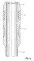
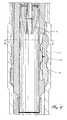
- a substantially vertical wellbore 10is shown with an upper lateral wellbore 12 and a lower lateral wellbore 14 drilled to intersect an upper producing zone 16 and an intermediate producing zone 18, as is well known to those skilled in the art of multilateral drilling.
- a production tubing 20is suspended inside the vertical wellbore 10 for recovery of fluids to the earth's surface.
- Adjacent to an upper lateral well junction 22is an upper fluid flow control apparatus 24 of the present invention while a lower fluid flow control apparatus 26 of the present invention is located adjacent to a lower lateral well junction 28.
- Each fluid flow control apparatus 24 and 26are the same as or similar in configuration.
- the fluid flow control apparatus 24 and 26generally comprises a generally cylindrical mandrel body having a central longitudinal bore extending therethrough, with threads or other connection devices on one end thereof for interconnection to the production tubing 20.
- a selectively operable lateral access dooris provided in the mandrel body for alternately permitting and preventing a service tool from laterally exiting the body therethrough and into a lateral wellbore.
- a selectively operable flow control valveis provided in the body for regulating fluid flow between the outside of the body and the central bore.
- a lateral access door 30comprises an opening in the body and a door or plug member.
- the doormay be moved longitudinally or radially, and may be moved by one or more means, as will be described in more detail below.
- the door 30is shown oriented toward its respective adjacent lateral wellbore.
- a pair of permanent or retrievable elastomeric packers 32are provided on separate bodies that are connected by threads to the mandrel body or, preferably, are connected as part of the mandrel body.
- the packers 32are used to isolate fluid flow between producing zones 16 and 18 and provide a fluidic seal thereby preventing co-mingling flow of produced fluids through a wellbore annulus 34.
- a lowermost packer 36is provided to anchor the production tubing 20, and to isolate a lower most producing zone (not shown) from the producing zones 16 and 18 above.
- a communication conduit or cable or conduit 38is shown extending from the fluid flow control apparatus 26, passing through the isolation packers 32, up to a surface control panel 40.
- a tubing plug 42which is well known, may be used to block flow from the lower most producing zone (not shown) into the tubing 20.
- Hydrocarbons 44 present thereinwill flow from the formation 16, through the upper lateral wellbore 12, into the annulus 34 of the vertical wellbore 10, into a set of ports 46 in the mandrel body and into the interior of the production tubing 20. From there, the produced hydrocarbons move to the surface.
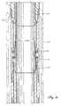
- FIGS. 2 A-Gwhich, when taken together illustrate the fluid flow control apparatus 24.
- An upper connector 48is provided on a generally cylindrical mandrel body 50 for sealable engagement with the production tubing 20.
- An elastomeric packing element 52 and a gripping device 54are connected to the mandrel body 50.
- a first communication conduit 56preferably, but not limited to electrical communication
- a second communication conduit 58preferably, but not limited to hydraulic control communication, extend from the earth's surface into the mandrel 50.
- the first 56 and second 58 communication conduitscommunicate their respective signals to/from the earth's surface and into the mandrel 50 around a set of bearings 60 to a slip joint 62.
- the electrical communication conduit or cable 56connects at this location, while the hydraulic communication conduit 58 extends therepast.
- the bearings 60reside in a rotating swivel joint 64, which allows the mandrel body 50 and its lateral access door 30 to be rotated relative tubing 20, to ensure that the lateral access door 30 is properly aligned with the lateral wellbore.
- the electrical communication conduit or cable 56communicates with a first pressure transducer 66 to monitor annulus pressure, a temperature and pressure sensor 68 to monitor temperature and hydraulic pressure, and/or a second pressure transducer 70 to monitor tubing pressure. Signals from these transducers are communicated to the control panel 40 on the surface so operations personnel can make informed decisions about downhole conditions.
- the electrical communication conduit or cablealso communicates with a solenoid valve 72, which selectively controls the flow of hydraulic fluid from the hydraulic communication conduit 58 to an upper hydraulic chamber 74, across a movable piston 76, to a lower hydraulic chamber 78.
- the differential pressures in these two chambers 74 and 78move the operating piston 76 a sleeve extending therefrom in relation to an annularly openable port or orifice 80 in the mandrel body 50 to allow hydrocarbons to flow from the annulus 34 to the tubing 20.
- the rate of fluid flowcan be controlled by adjusting the relative position of the piston 76 through the use of a flow control position indicator 82, which provides the operator constant and instantaneous feedback as to the size of the opening selected.
- An alternate and redundant method of opening or closing the flow control valve and the annularly operable orifice 80uses a coiled tubing deployed shifting tool 84 landed in a profile in the internal surface of the mandrel body 50. Pressure applied to this shifting tool 84 is sufficient to move the flow control valve to either the open or closed positions as dictated by operational necessity, as can be understood by those skilled in the art.
- the electrical communication conduit or cable 58further communicates electrical power to an high torque rotary motor 88 which rotates a pinion gear 90 to rotate a lateral access plug member or door 92.
- This rotational forceopens and closes the rotating lateral access door 92 should entry into the lateral wellbore be required. In some instances, however, normal operation rotating lateral access door 92 may not be possible for any number of reasons.
- An alternate, and redundant method of opening the rotating lateral access door 92is also provided wherein a coiled tubing deployed rotary tool 94 is shown located in a lower profile 96 in the interior of the mandrel body 50. Pressure applied to this rotary tool 94 is sufficient to rotate the rotating lateral access door 92 to either the open or closed positions as dictated by operational necessity, as would be well known to those skilled in the art.
- the depth and azimuthal orientationis controlled by a spring loaded, selective orienting key 98 on the mandrel body 50 which interacts with an orienting sleeve within a casing nipple, which is well known to those skilled in the art. Isolation of the producing zone is assured by the second packing element 52, and the gripping device 54, both mounted on the mandrel body 50, where an integrally formed lower connector 100 for sealable engagement with the production tubing 20 resides.
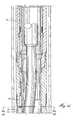
- FIGS 3 A-Hwhich, when taken together illustrate the upper fluid flow control apparatus 24, set and operating in a well casing 102.
- an upper valve seat 104 on the mandrel 50 and a lower 106 valve seat on the piston 76are shown sealably engaged, thereby blocking fluid flow.
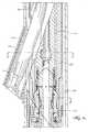
- the lateral access door 92is in the form of a plug member that is formed at an angle to facilitate movement of service tools into and out of the lateral.
- a coiled tubing 108or other well known remediation tool, can be easily inserted in the lateral wellbore.
- a flexible tubing member 110is shown attached to the coiled tubing 108, which is in turn, attached to a pulling tool 112, that is being inserted in a cased lateral 114.
- a selective orienting deflector tool 116is shown set in a profile 118 formed in the interior surface of the upper fluid flow control apparatus 24.
- the deflector tool 116is located, oriented, and held in position by a set of locking keys 120, which serves to direct any particular service tool inserted in the vertical wellbore 10, into the proper cased lateral 114.
- the depth and azimuthal orientation of the assembly as hereinabove discussedis controlled by a spring loaded, selective orienting key 98, which sets in a casing profile 122 of a casing nipple 124. Isolation of the producing zone is assured by the second packing element 52, and the gripping device 54, both mounted on the central mandrel 50.
- Figure 4 A-Bis a cross section taken at "A-A" of Figure 3-D and represents a view of the top of the rotating lateral access door 92.
- Figure 4-Aillustrates the relationship of the well casing 102, the cased lateral 114, the pinion gear 90, and the rotating lateral access door 92, shown in the open position.
- Figure 4-Billustrates the relationship of the well casing 102, the cased lateral 114, the pinion gear 90, and the rotating lateral access door 92, shown in the closed position.
- Figure 5is a cross section taken at "B-B” of Figure 3-E, and is shown without the flexible tubing member 110 in place, at a location at the center of the intersection of the cased lateral 114, and the well casing 102.
- This diagramshows the rotating lateral access door 92 in the open position, and a door seal 126.
- Figure 6is a cross section taken at "D-D" of Figure 3-F and illustrates in cross section the manner in which the selective orienting key 98 engages the casing nipple 124 assuring the assembly described herein is located and oriented at the correct position in the well.
- FIG 7is a longitudinal section taken at "C-C” of Figure 5.
- This diagramprimarily depicts the manner in which the door seal 126 seals around an elliptical opening 128 formed by the intersection of the cylinders formed by the cased lateral 114 and the rotating lateral access door 92.
- This viewclearly shows the bevel used to ease movement of service tools into and out of the cased lateral 114.
- the final diagram, Figure 8,is a cross section taken at "E-E" of Figure 3-E. This shows the relationship of the casing nipple 124, the orienting deflector tool 116, the profile 118 formed in the interior surface of the upper fluid flow control apparatus 24, and how the locking keys 120 interact with the profile 118.
- the oil well production system of the present inventionis utilized in wells with a plurality of producing formations which may be selectively produced.
- a tubing plug 42would need to be set in the tubing to isolate the lower producing zone (not shown).
- the operator standing at the control panelwould then configure the control panel 40 to close the lower fluid flow control apparatus 26, and open the upper fluid flow control apparatus 24. Both rotating lateral access doors 30 would be configured closed.
- Entry of the service tool in the lateralcould then be accomplished, preferably by coiled tubing or a flexible tubing such as CO-FLEXIP brand pipe, because the production tubing 20 now has an opening oriented toward the lateral, and a tool is present to deflect tools running in the tubing into the desired lateral. Production may be easily resumed by configuring the flow control valves as before.
Landscapes
- Geology (AREA)
- Life Sciences & Earth Sciences (AREA)
- Engineering & Computer Science (AREA)
- Mining & Mineral Resources (AREA)
- Environmental & Geological Engineering (AREA)
- Fluid Mechanics (AREA)
- Physics & Mathematics (AREA)
- General Life Sciences & Earth Sciences (AREA)
- Geochemistry & Mineralogy (AREA)
- Earth Drilling (AREA)
- Pipe Accessories (AREA)
- Physical Or Chemical Processes And Apparatus (AREA)
- Selective Calling Equipment (AREA)
Abstract
Description
The present invention relates to subsurface well completion equipment and, moreparticularly, to methods and related apparatus for remotely controlling fluid recoveryfrom multiple laterally drilled wellbores.
Hydrocarbon recovery volume from a vertically drilled well can be increased bydrilling additional wellbores from that same well. For example, the fluid recovery rateand the well's economic life can be increased by drilling a horizontal interval from a mainwellbore radially outward into one or more formations. Still further increases inrecovery and well life can be attained by drilling multiple horizontal intervals intomultiple formations. Once the multilateral wellbores have been drilled and completedthere is a need for the recovery of fluids from each wellbore to be individuallycontrolled. Currently, the control of the fluid recovery from these multilateral wellboreshas been limited in that once a lateral wellbore has been opened it is not possible toselectively close off and/or reopen the lateral wellbores without the need for the use ofadditional equipment, such as wireline units, coiled tubing units and workover rigs.
The need for selective fluid recovery is important in that individual producingintervals usually contain hydrocarbons that have different physical and chemicalproperties and as such may have different unit values. Co-mingling a valuable anddesirable crude with one that has, for instance, a high sulphur content would not becommercially expedient, and in some cases is prohibited by governmental regulatoryauthorities. Also, because different intervals inherently contain differing volumes ofhydrocarbons, it is highly probable that one interval will deplete before the others, andwill need to be easily and inexpensively closed off from the vertical wellbore before theother intervals.
The use of workover rigs, coiled tubing units and wireline units are relatively inexpensive if used onshore and in typical oilfield locations; however, mobilizing theseresources for a remote offshore well can be very expensive in terms of actual dollarsspent, and in terms of lost production while the resources are being moved on site. Inthe case of subsea wells (where no surface platform is present), a drill ship or workovervessel mobilization would be required to merely open/close a downhole wellbore valve.
The following patents disclose the current multilateral drilling and completiontechniques. U.S. Patent 4,402,551 details a simple completion method when a lateralwellbore is drilled and completed through a bottom of an existing traditional, verticalwellbore. Control of production fluids from a well completed in this manner is bytraditional surface wellhead valving methods, since improved methods of recovery fromonly one lateral and one interval is disclosed. The importance of this patent is therecognition of the role of orienting and casing the lateral wellbore, and the care takenin sealing the juncture where the vertical borehole interfaces with the lateral wellbore.
U.S. Patent 5,388,648 discloses a method and apparatus for sealing the juncturebetween one or more horizontal wells using deformable sealing means. This completionmethod deals primarily with completion techniques prior to insertion of productiontubing in the well. While it does address the penetration of multiple intervals at differentdepths in the well, it does not offer solutions as to how these different intervals may beselectively produced.
U.S. Patent 5,337,808 discloses a technique and apparatus for selective multizonevertical and/or horizontal completions. This patent illustrates the need toselectively open and close individual intervals in wells where multiple intervals exist, anddiscloses devices that isolate these individual zones through the use of workover rigs.
U.S. Patent 5,447,201 discloses a well completion system with selective remote surface control of individual producing zones to solve some of the above describedproblems. Similarly, U.S. Patent 5,411,085, commonly assigned hereto, discloses aproduction completion system which can be remotely manipulated by a controllingmeans extending between downhole components and a panel located at the surface.Each of these patents, while able to solve recovery problems without a workover rig,fails to address the unique problems associated with multilateral wells, and teaches onlyrecovery methods from multiple interval wells. A multi-lateral well that requires reentryremediation which was completed with either of these techniques has the same problemsas before: the production tubing would have to be removed, at great expense, to re-enterthe lateral for remediation, and reinserted in the well to resume production.
U.S. Patent 5,474,131 discloses a method for completing multi-lateral wells andmaintaining selective re-entry into the lateral wellbores. This method allows for re-entryremediation into horizontal laterals, but does not address the need to remotelymanipulate downhole completion accessories from the surface without some interventiontechnique. In this patent, a special shifting tool is required to be inserted in the well oncoiled tubing to engage a set of ears to shift a flapper valve to enable selective entry toeither a main wellbore or a lateral. To accomplish this, the well production must behalted, a coiled tubing company called to the jobs site, a surface valving system attachedto the wellhead must be removed, a blow out preventer must be attached to thewellhead, a coiled tubing injector head must be attached to the blow out preventer, andthe special shifting tool must be attached to the coiled tubing; all before the coiled tubingcan be inserted in the well.
U.S. Patent 2,304,303 describes a flow control assembly comprising a bodyhaving a central bore extending therethrough and having means on one end for interconnection to a well tubing. A selectively operable access door is provided in thebody for alternately permitting and preventing a service tool from laterally exiting thebody therethrough.
There is a need for a system to allow an operator standing at a remote controlpanel to selectively permit and prohibit flow from multiple lateral well branches drilledfrom a common central wellbore without having to resort to common interventiontechniques. Alternately, there is a need for an operator to selectively open and close avalve to implement re-entry into a lateral branch drilled from the common wellbore.There is a need for redundant power sources to assure operation of these automateddownhole devices, should one or more power sources fail. Finally, there is a need forfail safe mechanical recovery tools, should these automated systems become inoperative.
The present invention has been contemplated to overcome the foregoingdeficiencies and meet the above described needs. Specifically, the present invention isa system to recover fluids from a well that has either multiple intervals adjacent to acentral wellbore or has multiple lateral wellbores which have been drilled from a centralwellbore into a plurality of intervals in proximity to the central wellbore. In accordancewith the present invention an improved method is disclosed to allow selective recoveryfrom any of a well's intervals by remote control from a panel located at the earth'ssurface. This selective recovery is enabled by any number of well known controllingmeans, i.e. by electrical signal, by hydraulic signal, by fiber optic signal, or anycombination thereof, such combination comprising a piloted signal of one of thesecontrolling means to operate another. Selective control of producing formations wouldpreclude the necessity of expensive, but commonly practised workover techniques tochange producing zones, such as: (1) standard tubing conveyed intervention, should a production tubing string need to be removed or deployed in the well, or (2) should awork string need to be utilized for remediation, and would also reduce the need andfrequency of either (3) coiled tubing remediation or (4) wireline procedures to enact aworkover, as well.
Preferably, these controlling means may be independent and redundant, to assureoperation of the production system in the event of primary control failure; and may beoperated mechanically by the aforementioned commonly practised workover techniquesto change producing zones, should the need arise.
In a preferred embodiment, a well comprising a central casing adjacent at leasttwo hydrocarbon producing formations is cemented in the earth. A production tubingstring located inside the casing is fixed by any of several well known completionaccessories. Packers, which are well known to those skilled in the art, straddle each ofthe producing formations and seal an annulus, thereby preventing the produced wellborefluids from flowing to the surface in the annulus. A surface activated flow control valvewith an annularly openable orifice, located between the packers, may be opened orclosed upon receipt of a signal transmitted from the control panel, with each producingformation, between a wellhead at the surface and the lowermost producing formation,having a corresponding flow control valve. With such an arrangement, any formationcan be produced by opening its corresponding flow control valve and closing all otherflow control valves in the wellbore. Thereafter, co-mingled flow from individualformations is prevented, or allowed, as is desired by the operations personnel at thesurface control panel. Further, the size of the annularly openable orifice can be adjustedfrom the surface control panel such that the rate of flow of hydrocarbons therefrom canbe adjusted as operating conditions warrant.
Should conditions in one or more of the laterals warrant re-entry by either coiledtubing or other well known methods, a rotating lateral access door directly adjacent toand oriented toward each lateral in the well can be selectively opened, upon receipt ofa signal from the control panel above. The access door, in the open position, directsservice tools inserted into the central wellbore into the selected lateral. Closure of theaccess door, prevents entry of service tools running in the central wellbore from enteringlaterals that were not selected for remediation.
In accordance with this preferred embodiment, should either the flow controlvalve or the rotating lateral access door lose communication with the surface controlpanel, or should either device become otherwise inoperable by remote control,mechanical manipulation devices that may be deployed by coiled tubing are within thescope of this invention and are disclosed herein.
The features and advantages of the present invention will be appreciated andunderstood by those skilled in the art from the following detailed description anddrawings., in which:
The present invention is a system for remotely controlling multilateral wells, andwill be described in conjunction with its use in a well with three producing formationsfor purposes of illustration only. One skilled in the art will appreciate many differingapplications of the described apparatus. It should be understood that the describedinvention may be used in multiples for any well with a plurality of producing formationswhere either multiple lateral branches of a well are present, or multiple producingformations that are conventionally completed, such as by well perforations or uncasedopen hole, or by any combination of these methods. Specifically, the apparatus of thepresent invention includes enabling devices for automated remote control and access ofmultiple formations in a central wellbore during production, and allow work and time saving intervention techniques when remediation becomes necessary.
For the purposes of this discussion, the terms "upper" and "lower", "up hole" and"downhole", and "upwardly" and downwardly" are relative terms to indicate position anddirection of movement in easily recognized terms. Usually, these terms are relative toa line drawn from an upmost position at the surface to a point at the center of the earth,and would be appropriate for use in relatively straight, vertical wellbores. However,when the wellbore is highly deviated, such as from about 60 degrees from vertical, orhorizontal these terms do not make sense and therefore should not be taken aslimitations. These terms are only used for ease of understanding as an indication of whatthe position or movement would be if taken within a vertical wellbore.
Referring now to Figure 1, a substantiallyvertical wellbore 10 is shown with anupperlateral wellbore 12 and a lowerlateral wellbore 14 drilled to intersect an upperproducingzone 16 and an intermediate producing zone 18, as is well known to thoseskilled in the art of multilateral drilling. Aproduction tubing 20 is suspended inside thevertical wellbore 10 for recovery of fluids to the earth's surface. Adjacent to an upperlateral well junction 22 is an upper fluidflow control apparatus 24 of the presentinvention while a lower fluidflow control apparatus 26 of the present invention islocated adjacent to a lowerlateral well junction 28. Each fluidflow control apparatus flow control apparatus productiontubing 20. A selectively operable lateral access door is provided in the mandrel body foralternately permitting and preventing a service tool from laterally exiting the body therethrough and into a lateral wellbore. In addition, in one preferred embodiment, aselectively operable flow control valve is provided in the body for regulating fluid flowbetween the outside of the body and the central bore.
In the fluid flow control apparatus 24 alateral access door 30 comprises anopening in the body and a door or plug member. The door may be moved longitudinallyor radially, and may be moved by one or more means, as will be described in more detailbelow. In Figure 1 thedoor 30 is shown oriented toward its respective adjacent lateralwellbore. A pair of permanent or retrievableelastomeric packers 32 are provided onseparate bodies that are connected by threads to the mandrel body or, preferably, areconnected as part of the mandrel body. Thepackers 32 are used to isolate fluid flowbetween producingzones 16 and 18 and provide a fluidic seal thereby preventing co-minglingflow of produced fluids through awellbore annulus 34. Alowermost packer 36 is provided to anchor theproduction tubing 20, and to isolate a lower mostproducing zone (not shown) from the producingzones 16 and 18 above. Acommunication conduit or cable orconduit 38 is shown extending from the fluidflowcontrol apparatus 26, passing through theisolation packers 32, up to asurface controlpanel 40. Atubing plug 42, which is well known, may be used to block flow from thelower most producing zone (not shown) into thetubing 20.
A well with any multiple of producing zones can be completed in this fashion,and a large number of flow configurations can be attained with the apparatus of thepresent invention. For the purposes of discussion, all these possibilities will not bediscussed, but remain within the scope of the present invention. In the configurationshown in Figure 1, theproduction tubing 20 is plugged at the lower end by thetubingplug 42, the lower fluidflow control apparatus 26 has a flow control valve is shown closed, and the upper fluidflow control apparatus 24 is shown with its flow controlvalve in the open position. This production configuration is managed by an operatorstanding on the surface at thecontrol panel 40, and can be changed therewith bymanipulation of the controls on that panel. In this production configuration, flow fromall producing formations is blocked, except from the upper producingzone 16.Hydrocarbons 44 present therein will flow from theformation 16, through the upperlateral wellbore 12, into theannulus 34 of thevertical wellbore 10, into a set ofports 46in the mandrel body and into the interior of theproduction tubing 20. From there, theproduced hydrocarbons move to the surface.
Turning now to Figures 2 A-G, which, when taken together illustrate the fluidflow control apparatus 24. Anupper connector 48 is provided on a generallycylindricalmandrel body 50 for sealable engagement with theproduction tubing 20. Anelastomericpacking element 52 and agripping device 54 are connected to themandrel body 50. Afirst communication conduit 56, preferably, but not limited to electrical communication,and asecond communication conduit 58, preferably, but not limited to hydraulic controlcommunication, extend from the earth's surface into themandrel 50. The first 56 andsecond 58 communication conduits communicate their respective signals to/from theearth's surface and into themandrel 50 around a set ofbearings 60 to a slip joint 62.The electrical communication conduit orcable 56 connects at this location, while thehydraulic communication conduit 58 extends therepast. Thebearings 60 reside in arotating swivel joint 64, which allows themandrel body 50 and itslateral access door 30to be rotatedrelative tubing 20, to ensure that thelateral access door 30 is properlyaligned with the lateral wellbore. Further, the electrical communication conduit orcable 56 communicates with afirst pressure transducer 66 to monitor annulus pressure, a temperature andpressure sensor 68 to monitor temperature and hydraulic pressure,and/or asecond pressure transducer 70 to monitor tubing pressure. Signals from thesetransducers are communicated to thecontrol panel 40 on the surface so operationspersonnel can make informed decisions about downhole conditions.
In this preferred embodiment, the electrical communication conduit or cable alsocommunicates with asolenoid valve 72, which selectively controls the flow of hydraulicfluid from thehydraulic communication conduit 58 to an upperhydraulic chamber 74,across amovable piston 76, to a lowerhydraulic chamber 78. The differential pressuresin these twochambers orifice 80 in themandrel body 50to allow hydrocarbons to flow from theannulus 34 to thetubing 20. Further, the rateof fluid flow can be controlled by adjusting the relative position of thepiston 76 throughthe use of a flowcontrol position indicator 82, which provides the operator constant andinstantaneous feedback as to the size of the opening selected.
In some instances, however, normal operation of the flow control valve may notbe possible for any number of reasons. An alternate and redundant method of openingor closing the flow control valve and the annularlyoperable orifice 80 uses a coiledtubing deployed shiftingtool 84 landed in a profile in the internal surface of themandrelbody 50. Pressure applied to this shiftingtool 84 is sufficient to move the flow controlvalve to either the open or closed positions as dictated by operational necessity, as canbe understood by those skilled in the art.
The electrical communication conduit orcable 58 further communicates electricalpower to an hightorque rotary motor 88 which rotates apinion gear 90 to rotate alateral access plug member ordoor 92. This rotational force opens and closes the rotatinglateral access door 92 should entry into the lateral wellbore be required. In someinstances, however, normal operation rotatinglateral access door 92 may not be possiblefor any number of reasons. An alternate, and redundant method of opening the rotatinglateral access door 92 is also provided wherein a coiled tubing deployedrotary tool 94is shown located in alower profile 96 in the interior of themandrel body 50. Pressureapplied to thisrotary tool 94 is sufficient to rotate the rotatinglateral access door 92 toeither the open or closed positions as dictated by operational necessity, as would be wellknown to those skilled in the art.
When thefluid flow apparatus mandrel body 50 which interacts with an orienting sleeve within a casing nipple,which is well known to those skilled in the art. Isolation of the producing zone isassured by thesecond packing element 52, and thegripping device 54, both mounted onthemandrel body 50, where an integrally formedlower connector 100 for sealableengagement with theproduction tubing 20 resides.
Referring now to Figures 3 A-H, which, when taken together illustrate the upperfluidflow control apparatus 24, set and operating in awell casing 102. In thisembodiment, anupper valve seat 104 on themandrel 50 and a lower 106 valve seat onthepiston 76 are shown sealably engaged, thereby blocking fluid flow. Thelateralaccess door 92 is in the form of a plug member that is formed at an angle to facilitatemovement of service tools into and out of the lateral. Once so opened, a coiled tubing108, or other well known remediation tool, can be easily inserted in the lateral wellbore.For purposes of illustration, aflexible tubing member 110 is shown attached to thecoiled tubing 108, which is in turn, attached to a pullingtool 112, that is being inserted in acased lateral 114.
A selectiveorienting deflector tool 116 is shown set in aprofile 118 formed inthe interior surface of the upper fluidflow control apparatus 24. Thedeflector tool 116is located, oriented, and held in position by a set of lockingkeys 120, which serves todirect any particular service tool inserted in thevertical wellbore 10, into the propercasedlateral 114.
The depth and azimuthal orientation of the assembly as hereinabove discussedis controlled by a spring loaded, selective orienting key 98, which sets in acasing profile 122 of acasing nipple 124. Isolation of the producing zone is assured by thesecondpacking element 52, and thegripping device 54, both mounted on thecentral mandrel 50.
Figure 4 A-B is a cross section taken at "A-A" of Figure 3-D and represents aview of the top of the rotatinglateral access door 92. Figure 4-A illustrates therelationship of thewell casing 102, the casedlateral 114, thepinion gear 90, and therotatinglateral access door 92, shown in the open position. Figure 4-B illustrates therelationship of thewell casing 102, the casedlateral 114, thepinion gear 90, and therotatinglateral access door 92, shown in the closed position. Referring now to Figure5, which is a cross section taken at "B-B" of Figure 3-E, and is shown without theflexible tubing member 110 in place, at a location at the center of the intersection of thecasedlateral 114, and thewell casing 102. This diagram shows the rotatinglateralaccess door 92 in the open position, and adoor seal 126. Figure 6 is a cross sectiontaken at "D-D" of Figure 3-F and illustrates in cross section the manner in which theselective orienting key 98 engages thecasing nipple 124 assuring the assembly describedherein is located and oriented at the correct position in the well.
Turning now to Figure 7, which is a longitudinal section taken at "C-C" ofFigure 5. This diagram primarily depicts the manner in which thedoor seal 126 sealsaround anelliptical opening 128 formed by the intersection of the cylinders formed bythe casedlateral 114 and the rotatinglateral access door 92. This view clearly showsthe bevel used to ease movement of service tools into and out of the casedlateral 114.The final diagram, Figure 8, is a cross section taken at "E-E" of Figure 3-E. This showsthe relationship of thecasing nipple 124, the orientingdeflector tool 116, theprofile 118formed in the interior surface of the upper fluidflow control apparatus 24, and how thelockingkeys 120 interact with theprofile 118.
In a typical operation, the oil well production system of the present invention isutilized in wells with a plurality of producing formations which may be selectivelyproduced. Referring once again to Figure 1, if it were operationally desirable to producefrom the upper producingzone 16 without co-mingling the flow with the hydrocarbonsfrom the other formations; first atubing plug 42 would need to be set in the tubing toisolate the lower producing zone (not shown). The operator standing at the controlpanel would then configure thecontrol panel 40 to close the lower fluidflow controlapparatus 26, and open the upper fluidflow control apparatus 24. Both rotatinglateralaccess doors 30 would be configured closed. In this configuration, flow is blocked fromboth the intermediate producing zone 18, and the lower producing zone andhydrocarbons from the upper producing zone would enter theupper lateral 12, flow intotheannulus 34, through the set ofports 46 on the upper fluidflow control apparatus 24,and into theproduction tubing 20, which then moves to the surface. Different flowregimes can be accomplished simply by altering the arrangement of the open and closedvalves from the control panel, and moving the location of thetubing plug 42. The necessity of thetubing plug 42 can be eliminated by utilizing another flow control valveto meter flow from the lower formation as well.
When operational necessity dictates that one or more of the laterals requires re-entry,a simple operation is all that is necessary to gain access therein. For example,assume theupper lateral 12 is chosen for remediation. The operator at theremotecontrol panel 40 shuts all flow control valves, assures that all rotatinglateral accessdoors 30 are closed except the one adjacent theupper lateral 12, which would beopened. If the orientingdeflector tool 116 is not installed, it would become necessaryto install it at this time by any of several well known methods. In all probability,however, thedeflector tool 116 would already be in place. Entry of the service tool inthe lateral could then be accomplished, preferably by coiled tubing or a flexible tubingsuch as CO-FLEXIP brand pipe, because theproduction tubing 20 now has an openingoriented toward the lateral, and a tool is present to deflect tools running in the tubinginto the desired lateral. Production may be easily resumed by configuring the flowcontrol valves as before.
Whereas the present invention has been described in particular relation to thedrawings attached hereto, it should be understood that other and further modifications,apart from those shown or suggested herein, may be made within the scope of thepresent invention as defined in the appended claims.
Claims (6)
- A multilateral production system comprising:a production tubing defining an interior bore;a main wellbore adapted to receive fluid flow;one or more lateral wellbores adapted to receive fluid flow;a plurality of flow control valves interconnected with the productiontubing, each of the plurality of flow control valves in communicationwith the fluid flow of at least one of the main wellbore and the one ormore lateral wellbores, the plurality of flow control valves adapted toregulate fluid flow between the wellbores and the interior bore of theproduction tubing; andat least one of the flow control valves associated with the one or morelateral wellbores being operable from the surface.
- The multilateral production system of Claim 1, wherein the flow controlvalves are sleeve valves.
- The system of Claim 1, wherein:the one or more lateral wellbores comprises a first and a second lateralwellbore;the plurality of flow control valves comprises a first flow controlvalve, a second flow control valve and a third flow control valve;the first flow control valve is adapted to regulate the fluid flow fromthe main wellbore;the second flow control valve is adapted to regulate the fluid flowfrom the first lateral wellbore; andthe third flow control valve is adapted to regulate the fluid flow fromthe second lateral wellbore.
- The system of Claim 3, wherein:wherein when the second flow control valve is in its open position,fluid from the first lateral wellbore flows into the production tubingthrough the second flow control valve; andthe second flow control valve is operable from the surface to varybetween its open position and its closed position;
when the second flow control valve is in its closed position, fluidfrom the first lateral wellbore is prevented from entering theproduction tubing through the closed second flow control valve. - The system of Claim 3, wherein:wherein when the third flow control valve is in its open position, fluidfrom the second lateral wellbore flows into the production tubing through the third flow control valve; andthe third flow control valve is operable from the surface to varybetween its open position and its closed position;
when the third flow control valve is in its closed position, fluid fromthe second lateral wellbore is prevented from entering the productiontubing through the closed third flow control valve. - A method of controlling flow in a multilateral well, the method comprising:receiving fluid flow from a main wellbore and one or more lateralwellbores;providing a first flow control valve in communication with the mainwellbore;providing one or more selectively operable lateral flow control valvesin communication with the one or more lateral wellbores, each of theone or more lateral flow control valves having a central bore, each ofthe one or more lateral flow control valves being interconnected to aproduction tubing, and each of the one or more lateral flow controlvalves being operable from the surface; andselectively regulating the flow of fluid into the central bores of theone or more lateral control valves.
Applications Claiming Priority (4)
| Application Number | Priority Date | Filing Date | Title |
|---|---|---|---|
| US638027 | 1985-07-09 | ||
| US08/638,027US5918669A (en) | 1996-04-26 | 1996-04-26 | Method and apparatus for remote control of multilateral wells |
| EP99122622AEP0987400B1 (en) | 1996-04-26 | 1997-04-23 | Method and apparatus for remote control of multilateral wells |
| EP97919528AEP0895561B1 (en) | 1996-04-26 | 1997-04-23 | Method and apparatus for remote control of multilateral wells |
Related Parent Applications (1)
| Application Number | Title | Priority Date | Filing Date |
|---|---|---|---|
| EP99122622ADivisionEP0987400B1 (en) | 1996-04-26 | 1997-04-23 | Method and apparatus for remote control of multilateral wells |
Publications (2)
| Publication Number | Publication Date |
|---|---|
| EP1398457A2true EP1398457A2 (en) | 2004-03-17 |
| EP1398457A3 EP1398457A3 (en) | 2004-09-29 |
Family
ID=24558353
Family Applications (4)
| Application Number | Title | Priority Date | Filing Date |
|---|---|---|---|
| EP97919528AExpired - LifetimeEP0895561B1 (en) | 1996-04-26 | 1997-04-23 | Method and apparatus for remote control of multilateral wells |
| EP99122621AExpired - LifetimeEP1008719B1 (en) | 1996-04-26 | 1997-04-23 | Method and apparatus for remote control of multilateral wells |
| EP03026315AWithdrawnEP1398457A3 (en) | 1996-04-26 | 1997-04-23 | Method and apparatus for remote control of multilateral wells |
| EP99122622AExpired - LifetimeEP0987400B1 (en) | 1996-04-26 | 1997-04-23 | Method and apparatus for remote control of multilateral wells |
Family Applications Before (2)
| Application Number | Title | Priority Date | Filing Date |
|---|---|---|---|
| EP97919528AExpired - LifetimeEP0895561B1 (en) | 1996-04-26 | 1997-04-23 | Method and apparatus for remote control of multilateral wells |
| EP99122621AExpired - LifetimeEP1008719B1 (en) | 1996-04-26 | 1997-04-23 | Method and apparatus for remote control of multilateral wells |
Family Applications After (1)
| Application Number | Title | Priority Date | Filing Date |
|---|---|---|---|
| EP99122622AExpired - LifetimeEP0987400B1 (en) | 1996-04-26 | 1997-04-23 | Method and apparatus for remote control of multilateral wells |
Country Status (6)
| Country | Link |
|---|---|
| US (4) | US5918669A (en) |
| EP (4) | EP0895561B1 (en) |
| AU (1) | AU2396797A (en) |
| CA (1) | CA2252728C (en) |
| NO (1) | NO315581B1 (en) |
| WO (1) | WO1997041333A1 (en) |
Families Citing this family (73)
| Publication number | Priority date | Publication date | Assignee | Title |
|---|---|---|---|---|
| US6237683B1 (en)* | 1996-04-26 | 2001-05-29 | Camco International Inc. | Wellbore flow control device |
| GB9717572D0 (en)* | 1997-08-20 | 1997-10-22 | Hennig Gregory E | Main bore isolation assembly for multi-lateral use |
| AU732482B2 (en)* | 1997-09-03 | 2001-04-26 | Halliburton Energy Services, Inc. | Methods of completing and producing a subterranean well and associated apparatus |
| US6079494A (en)* | 1997-09-03 | 2000-06-27 | Halliburton Energy Services, Inc. | Methods of completing and producing a subterranean well and associated apparatus |
| US6283208B1 (en)* | 1997-09-05 | 2001-09-04 | Schlumberger Technology Corp. | Orienting tool and method |
| NO306418B1 (en)* | 1998-03-23 | 1999-11-01 | Rogalandsforskning | blowout preventer |
| US6073697A (en)* | 1998-03-24 | 2000-06-13 | Halliburton Energy Services, Inc. | Lateral wellbore junction having displaceable casing blocking member |
| US6247536B1 (en) | 1998-07-14 | 2001-06-19 | Camco International Inc. | Downhole multiplexer and related methods |
| RU2154726C2 (en)* | 1998-08-04 | 2000-08-20 | ОАО "Сургутнефтегаз" Трест "Сургутнефтегеофизика" | Method of selective development of productive seam by horizontal drilling |
| RU2148154C1 (en)* | 1998-09-08 | 2000-04-27 | Струкова Надежда Антоновна | Method of narrow oil fringes development |
| US6142229A (en)* | 1998-09-16 | 2000-11-07 | Atlantic Richfield Company | Method and system for producing fluids from low permeability formations |
| US6257338B1 (en) | 1998-11-02 | 2001-07-10 | Halliburton Energy Services, Inc. | Method and apparatus for controlling fluid flow within wellbore with selectively set and unset packer assembly |
| US6253857B1 (en)* | 1998-11-02 | 2001-07-03 | Halliburton Energy Services, Inc. | Downhole hydraulic power source |
| US6095248A (en)* | 1998-11-03 | 2000-08-01 | Halliburton Energy Services, Inc. | Method and apparatus for remote control of a tubing exit sleeve |
| US6863129B2 (en) | 1998-11-19 | 2005-03-08 | Schlumberger Technology Corporation | Method and apparatus for providing plural flow paths at a lateral junction |
| US6568469B2 (en)* | 1998-11-19 | 2003-05-27 | Schlumberger Technology Corporation | Method and apparatus for connecting a main well bore and a lateral branch |
| US6684952B2 (en)* | 1998-11-19 | 2004-02-03 | Schlumberger Technology Corp. | Inductively coupled method and apparatus of communicating with wellbore equipment |
| US6328112B1 (en)* | 1999-02-01 | 2001-12-11 | Schlumberger Technology Corp | Valves for use in wells |
| BR0009829B1 (en) | 1999-04-19 | 2009-08-11 | deep well equipment for use in a well casing pipe, and process for finishing a well. | |
| AU5591400A (en)* | 1999-06-01 | 2000-12-18 | Halliburton Energy Services, Inc. | System and method for actuating a remote device |
| US6227302B1 (en) | 1999-06-03 | 2001-05-08 | Cameo International, Inc. | Apparatus and method for controlling fluid flow in a wellbore |
| US6394181B2 (en)* | 1999-06-18 | 2002-05-28 | Halliburton Energy Services, Inc. | Self-regulating lift fluid injection tool and method for use of same |
| US6286596B1 (en)* | 1999-06-18 | 2001-09-11 | Halliburton Energy Services, Inc. | Self-regulating lift fluid injection tool and method for use of same |
| US6279660B1 (en)* | 1999-08-05 | 2001-08-28 | Cidra Corporation | Apparatus for optimizing production of multi-phase fluid |
| US6209649B1 (en)* | 1999-08-10 | 2001-04-03 | Camco International, Inc | Selective re-entry tool for multiple tubing completions and method of using |
| US6873267B1 (en) | 1999-09-29 | 2005-03-29 | Weatherford/Lamb, Inc. | Methods and apparatus for monitoring and controlling oil and gas production wells from a remote location |
| GB0002531D0 (en)* | 2000-02-04 | 2000-03-29 | Omega Completion Technology Li | Method of controlling access between a main boreand a lateral bore in a production system |
| US6561277B2 (en)* | 2000-10-13 | 2003-05-13 | Schlumberger Technology Corporation | Flow control in multilateral wells |
| US6481503B2 (en)* | 2001-01-08 | 2002-11-19 | Baker Hughes Incorporated | Multi-purpose injection and production well system |
| US6644412B2 (en)* | 2001-04-25 | 2003-11-11 | Weatherford/Lamb, Inc. | Flow control apparatus for use in a wellbore |
| US20030066649A1 (en)* | 2001-10-10 | 2003-04-10 | Koot Leo W. | Single well combination oil production/water dump flood apparatus and methods |
| US6722439B2 (en) | 2002-03-26 | 2004-04-20 | Baker Hughes Incorporated | Multi-positioned sliding sleeve valve |
| US20030188862A1 (en)* | 2002-04-03 | 2003-10-09 | Streich Steven G. | System and method for sensing and monitoring the status/performance of a downhole tool |
| NO324739B1 (en)* | 2002-04-16 | 2007-12-03 | Schlumberger Technology Bv | Release module for operating a downhole tool |
| US6789628B2 (en)* | 2002-06-04 | 2004-09-14 | Halliburton Energy Services, Inc. | Systems and methods for controlling flow and access in multilateral completions |
| US6945331B2 (en) | 2002-07-31 | 2005-09-20 | Schlumberger Technology Corporation | Multiple interventionless actuated downhole valve and method |
| US6915847B2 (en)* | 2003-02-14 | 2005-07-12 | Schlumberger Technology Corporation | Testing a junction of plural bores in a well |
| US7048061B2 (en)* | 2003-02-21 | 2006-05-23 | Weatherford/Lamb, Inc. | Screen assembly with flow through connectors |
| US7195033B2 (en)* | 2003-02-24 | 2007-03-27 | Weatherford/Lamb, Inc. | Method and system for determining and controlling position of valve |
| US7063146B2 (en)* | 2003-10-24 | 2006-06-20 | Halliburton Energy Services, Inc. | System and method for processing signals in a well |
| US7377319B2 (en)* | 2005-02-22 | 2008-05-27 | Halliburton Energy Services, Inc. | Downhole device to measure and record setting motion of packers and method of sealing a wellbore |
| RU2290498C1 (en)* | 2006-03-29 | 2006-12-27 | Открытое акционерное общество "Татнефть" им. В.Д. Шашина | Method for extracting oil deposit in heterogeneous collector of low thickness |
| US7735555B2 (en)* | 2006-03-30 | 2010-06-15 | Schlumberger Technology Corporation | Completion system having a sand control assembly, an inductive coupler, and a sensor proximate to the sand control assembly |
| US7712524B2 (en)* | 2006-03-30 | 2010-05-11 | Schlumberger Technology Corporation | Measuring a characteristic of a well proximate a region to be gravel packed |
| US7793718B2 (en) | 2006-03-30 | 2010-09-14 | Schlumberger Technology Corporation | Communicating electrical energy with an electrical device in a well |
| US8056619B2 (en) | 2006-03-30 | 2011-11-15 | Schlumberger Technology Corporation | Aligning inductive couplers in a well |
| US20080223585A1 (en)* | 2007-03-13 | 2008-09-18 | Schlumberger Technology Corporation | Providing a removable electrical pump in a completion system |
| US7708074B2 (en)* | 2007-09-14 | 2010-05-04 | Saudi Arabian Oil Company | Downhole valve for preventing zonal cross-flow |
| US20090255687A1 (en)* | 2008-04-10 | 2009-10-15 | Halliburton Energy Services, Inc. | Sealing Between Alignable Windows for Lateral Wellbore Drilling |
| US8347505B2 (en)* | 2008-10-13 | 2013-01-08 | Baker Hughes Incorporated | Method for fabricating a cylindrical spring by compressive force |
| US8668012B2 (en) | 2011-02-10 | 2014-03-11 | Halliburton Energy Services, Inc. | System and method for servicing a wellbore |
| US8695710B2 (en) | 2011-02-10 | 2014-04-15 | Halliburton Energy Services, Inc. | Method for individually servicing a plurality of zones of a subterranean formation |
| US8839850B2 (en)* | 2009-10-07 | 2014-09-23 | Schlumberger Technology Corporation | Active integrated completion installation system and method |
| US20110162839A1 (en)* | 2010-01-07 | 2011-07-07 | Henning Hansen | Retrofit wellbore fluid injection system |
| US20110192596A1 (en)* | 2010-02-07 | 2011-08-11 | Schlumberger Technology Corporation | Through tubing intelligent completion system and method with connection |
| US8893811B2 (en) | 2011-06-08 | 2014-11-25 | Halliburton Energy Services, Inc. | Responsively activated wellbore stimulation assemblies and methods of using the same |
| US9051798B2 (en)* | 2011-06-17 | 2015-06-09 | David L. Abney, Inc. | Subterranean tool with sealed electronic passage across multiple sections |
| US8899334B2 (en) | 2011-08-23 | 2014-12-02 | Halliburton Energy Services, Inc. | System and method for servicing a wellbore |
| US9249559B2 (en) | 2011-10-04 | 2016-02-02 | Schlumberger Technology Corporation | Providing equipment in lateral branches of a well |
| US9644476B2 (en) | 2012-01-23 | 2017-05-09 | Schlumberger Technology Corporation | Structures having cavities containing coupler portions |
| US9175560B2 (en) | 2012-01-26 | 2015-11-03 | Schlumberger Technology Corporation | Providing coupler portions along a structure |
| US9938823B2 (en) | 2012-02-15 | 2018-04-10 | Schlumberger Technology Corporation | Communicating power and data to a component in a well |
| US8991509B2 (en) | 2012-04-30 | 2015-03-31 | Halliburton Energy Services, Inc. | Delayed activation activatable stimulation assembly |
| US10036234B2 (en) | 2012-06-08 | 2018-07-31 | Schlumberger Technology Corporation | Lateral wellbore completion apparatus and method |
| US9784070B2 (en) | 2012-06-29 | 2017-10-10 | Halliburton Energy Services, Inc. | System and method for servicing a wellbore |
| US9784059B2 (en)* | 2012-10-12 | 2017-10-10 | Schlumberger Technology Corporation | Selective orientation and location system |
| US10472933B2 (en) | 2014-07-10 | 2019-11-12 | Halliburton Energy Services, Inc. | Multilateral junction fitting for intelligent completion of well |
| WO2016043737A1 (en)* | 2014-09-17 | 2016-03-24 | Halliburton Energy Services Inc. | Completion deflector for intelligent completion of well |
| WO2017209753A1 (en) | 2016-06-02 | 2017-12-07 | Halliburton Energy Services, Inc. | Multilateral intelligent completion with stackable isolation |
| CA3070953C (en) | 2017-09-19 | 2022-06-21 | Halliburton Energy Services, Inc. | Energy transfer mechanism for a junction assembly to communicate with a lateral completion assembly |
| US11125015B2 (en) | 2019-12-31 | 2021-09-21 | Sebastien Goudreault | Ladder anchor apparatus |
| CN114562205B (en)* | 2020-11-27 | 2024-12-20 | 中国石油化工股份有限公司 | Repeatable branch pipe drilling device and method |
| US12392221B2 (en)* | 2023-01-31 | 2025-08-19 | Saudi Arabian Oil Company | Controlling fluid flows in a multi-wellbore well system with a surface controlled formation isolation valve |
Family Cites Families (32)
| Publication number | Priority date | Publication date | Assignee | Title |
|---|---|---|---|---|
| US2304303A (en)* | 1939-08-21 | 1942-12-08 | Baash Ross Tool Co | Flow valve for wells |
| US2710655A (en)* | 1952-07-19 | 1955-06-14 | J B Nelson | Rotatable port control sleeve |
| US2803197A (en)* | 1954-08-23 | 1957-08-20 | Phillips Petroleum Co | Motor control circuit |
| US2797893A (en)* | 1954-09-13 | 1957-07-02 | Oilwell Drain Hole Drilling Co | Drilling and lining of drain holes |
| US3073392A (en)* | 1960-03-08 | 1963-01-15 | Us Industries Inc | Well apparatus |
| US3581820A (en)* | 1969-05-29 | 1971-06-01 | Erwin Burns | Port collar |
| US3665955A (en)* | 1970-07-20 | 1972-05-30 | George Eugene Conner Sr | Self-contained valve control system |
| US4094359A (en)* | 1977-05-27 | 1978-06-13 | Gearhart-Owen Industries, Inc. | Apparatus and methods for testing earth formations |
| US4124070A (en)* | 1977-09-06 | 1978-11-07 | Gearhart-Owen Industries, Inc. | Wireline shifting tool apparatus and methods |
| US4402551A (en)* | 1981-09-10 | 1983-09-06 | Wood Edward T | Method and apparatus to complete horizontal drain holes |
| US4700782A (en)* | 1986-11-07 | 1987-10-20 | Dresser Industries, Inc. | Flow control valve for use in oil and gas wells and the like |
| FR2621646B1 (en)* | 1987-08-19 | 1995-08-25 | Inst Francais Du Petrole | PROCESS FOR MANEUVERING AT LEAST ONE DEVICE WITHIN A TUBING AND ASSEMBLY FOR IMPLEMENTING THE PROCESS |
| US4945995A (en)* | 1988-01-29 | 1990-08-07 | Institut Francais Du Petrole | Process and device for hydraulically and selectively controlling at least two tools or instruments of a valve device allowing implementation of the method of using said device |
| US4856595A (en)* | 1988-05-26 | 1989-08-15 | Schlumberger Technology Corporation | Well tool control system and method |
| GB9025230D0 (en)* | 1990-11-20 | 1991-01-02 | Framo Dev Ltd | Well completion system |
| US5236047A (en)* | 1991-10-07 | 1993-08-17 | Camco International Inc. | Electrically operated well completion apparatus and method |
| US5253712A (en)* | 1992-03-02 | 1993-10-19 | Swor Loren C | Rotationally operated back pressure valve |
| US5311936A (en)* | 1992-08-07 | 1994-05-17 | Baker Hughes Incorporated | Method and apparatus for isolating one horizontal production zone in a multilateral well |
| US5474131A (en)* | 1992-08-07 | 1995-12-12 | Baker Hughes Incorporated | Method for completing multi-lateral wells and maintaining selective re-entry into laterals |
| US5322127C1 (en)* | 1992-08-07 | 2001-02-06 | Baker Hughes Inc | Method and apparatus for sealing the juncture between a vertical well and one or more horizontal wells |
| US5337808A (en)* | 1992-11-20 | 1994-08-16 | Natural Reserves Group, Inc. | Technique and apparatus for selective multi-zone vertical and/or horizontal completions |
| US5388648A (en)* | 1993-10-08 | 1995-02-14 | Baker Hughes Incorporated | Method and apparatus for sealing the juncture between a vertical well and one or more horizontal wells using deformable sealing means |
| US5411085A (en)* | 1993-11-01 | 1995-05-02 | Camco International Inc. | Spoolable coiled tubing completion system |
| US5439051A (en)* | 1994-01-26 | 1995-08-08 | Baker Hughes Incorporated | Lateral connector receptacle |
| US5564503A (en)* | 1994-08-26 | 1996-10-15 | Halliburton Company | Methods and systems for subterranean multilateral well drilling and completion |
| US5706896A (en)* | 1995-02-09 | 1998-01-13 | Baker Hughes Incorporated | Method and apparatus for the remote control and monitoring of production wells |
| US5706892A (en)* | 1995-02-09 | 1998-01-13 | Baker Hughes Incorporated | Downhole tools for production well control |
| US5531270A (en)* | 1995-05-04 | 1996-07-02 | Atlantic Richfield Company | Downhole flow control in multiple wells |
| GB9516632D0 (en)* | 1995-08-14 | 1995-10-18 | Pressure Control Engineering L | Through-tubing lateral re-entry |
| US5787987A (en)* | 1995-09-06 | 1998-08-04 | Baker Hughes Incorporated | Lateral seal and control system |
| US5715891A (en)* | 1995-09-27 | 1998-02-10 | Natural Reserves Group, Inc. | Method for isolating multi-lateral well completions while maintaining selective drainhole re-entry access |
| US5730224A (en)* | 1996-02-29 | 1998-03-24 | Halliburton Energy Services, Inc. | Slidable access control device for subterranean lateral well drilling and completion |
- 1996
- 1996-04-26USUS08/638,027patent/US5918669A/ennot_activeExpired - Lifetime
- 1997
- 1997-04-23AUAU23967/97Apatent/AU2396797A/ennot_activeAbandoned
- 1997-04-23EPEP97919528Apatent/EP0895561B1/ennot_activeExpired - Lifetime
- 1997-04-23EPEP99122621Apatent/EP1008719B1/ennot_activeExpired - Lifetime
- 1997-04-23EPEP03026315Apatent/EP1398457A3/ennot_activeWithdrawn
- 1997-04-23EPEP99122622Apatent/EP0987400B1/ennot_activeExpired - Lifetime
- 1997-04-23CACA002252728Apatent/CA2252728C/ennot_activeExpired - Fee Related
- 1997-04-23WOPCT/GB1997/001119patent/WO1997041333A1/enactiveIP Right Grant
- 1997-09-17USUS08/931,959patent/US5927401A/ennot_activeExpired - Lifetime
- 1997-09-29USUS08/939,223patent/US5823263A/ennot_activeExpired - Lifetime
- 1998
- 1998-10-13USUS09/170,298patent/US5960874A/ennot_activeExpired - Lifetime
- 1998-10-21NONO19984895Apatent/NO315581B1/ennot_activeIP Right Cessation
Also Published As
| Publication number | Publication date |
|---|---|
| CA2252728C (en) | 2006-07-11 |
| NO984895L (en) | 1998-12-23 |
| WO1997041333A1 (en) | 1997-11-06 |
| US5960874A (en) | 1999-10-05 |
| US5823263A (en) | 1998-10-20 |
| EP1398457A3 (en) | 2004-09-29 |
| EP1008719A1 (en) | 2000-06-14 |
| EP0987400B1 (en) | 2005-12-14 |
| NO984895D0 (en) | 1998-10-21 |
| US5927401A (en) | 1999-07-27 |
| EP0895561B1 (en) | 2000-09-06 |
| EP0895561A1 (en) | 1999-02-10 |
| AU2396797A (en) | 1997-11-19 |
| EP0987400A1 (en) | 2000-03-22 |
| US5918669A (en) | 1999-07-06 |
| EP1008719B1 (en) | 2004-06-23 |
| CA2252728A1 (en) | 1997-11-06 |
| NO315581B1 (en) | 2003-09-22 |
Similar Documents
| Publication | Publication Date | Title |
|---|---|---|
| EP0987400B1 (en) | Method and apparatus for remote control of multilateral wells | |
| US6308783B2 (en) | Wellbore flow control device | |
| US6840321B2 (en) | Multilateral injection/production/storage completion system | |
| US6513599B1 (en) | Thru-tubing sand control method and apparatus | |
| CA2952247C (en) | Multi-lateral well system | |
| US6003601A (en) | Methods of completing a subterranean well and associated apparatus | |
| US6830106B2 (en) | Multilateral well completion apparatus and methods of use | |
| EP1828538B1 (en) | Method and apparatus for fluid bypass of a well tool | |
| WO2012166418A2 (en) | Safety valve system for cable deployed electric submersible pump | |
| WO2017160278A1 (en) | Dual bore co-mingler with multiple position inner sleeve | |
| US6648073B1 (en) | Retrievable sliding sleeve flow control valve for zonal isolation control system | |
| EP1828537B1 (en) | Method and apparatus to hydraulically bypass a well tool | |
| CA2491444C (en) | Method and apparatus for remote control of multilateral wells | |
| CA2573379C (en) | Wellbore flow control device |
Legal Events
| Date | Code | Title | Description |
|---|---|---|---|
| PUAI | Public reference made under article 153(3) epc to a published international application that has entered the european phase | Free format text:ORIGINAL CODE: 0009012 | |
| 17P | Request for examination filed | Effective date:20031126 | |
| AC | Divisional application: reference to earlier application | Ref document number:0895561 Country of ref document:EP Kind code of ref document:P Ref document number:0987400 Country of ref document:EP Kind code of ref document:P | |
| AK | Designated contracting states | Kind code of ref document:A2 Designated state(s):FR GB | |
| PUAL | Search report despatched | Free format text:ORIGINAL CODE: 0009013 | |
| AK | Designated contracting states | Kind code of ref document:A3 Designated state(s):FR GB | |
| RIC1 | Information provided on ipc code assigned before grant | Ipc:7E 21B 41/00 B Ipc:7E 21B 43/14 B Ipc:7E 21B 43/12 A Ipc:7E 21B 43/30 B | |
| AKX | Designation fees paid | Designated state(s):FR GB | |
| STAA | Information on the status of an ep patent application or granted ep patent | Free format text:STATUS: THE APPLICATION IS DEEMED TO BE WITHDRAWN | |
| 18D | Application deemed to be withdrawn | Effective date:20061130 |