EP1397999B1 - Rod connector - Google Patents
Rod connectorDownload PDFInfo
- Publication number
- EP1397999B1 EP1397999B1EP03020810AEP03020810AEP1397999B1EP 1397999 B1EP1397999 B1EP 1397999B1EP 03020810 AEP03020810 AEP 03020810AEP 03020810 AEP03020810 AEP 03020810AEP 1397999 B1EP1397999 B1EP 1397999B1
- Authority
- EP
- European Patent Office
- Prior art keywords
- rod
- main body
- connector
- connector main
- shank
- Prior art date
- Legal status (The legal status is an assumption and is not a legal conclusion. Google has not performed a legal analysis and makes no representation as to the accuracy of the status listed.)
- Expired - Lifetime
Links
- 230000002265preventionEffects0.000claimsdescription2
- 210000000988bone and boneAnatomy0.000description4
- 239000007943implantSubstances0.000description3
- 238000006073displacement reactionMethods0.000description1
- 238000003780insertionMethods0.000description1
- 230000037431insertionEffects0.000description1
- 238000000034methodMethods0.000description1
- 230000000149penetrating effectEffects0.000description1
- 239000004576sandSubstances0.000description1
- 210000001562sternumAnatomy0.000description1
Images


Classifications
- A—HUMAN NECESSITIES
- A61—MEDICAL OR VETERINARY SCIENCE; HYGIENE
- A61B—DIAGNOSIS; SURGERY; IDENTIFICATION
- A61B17/00—Surgical instruments, devices or methods
- A61B17/56—Surgical instruments or methods for treatment of bones or joints; Devices specially adapted therefor
- A61B17/58—Surgical instruments or methods for treatment of bones or joints; Devices specially adapted therefor for osteosynthesis, e.g. bone plates, screws or setting implements
- A61B17/60—Surgical instruments or methods for treatment of bones or joints; Devices specially adapted therefor for osteosynthesis, e.g. bone plates, screws or setting implements for external osteosynthesis, e.g. distractors, contractors
- A61B17/64—Devices extending alongside the bones to be positioned
- A—HUMAN NECESSITIES
- A61—MEDICAL OR VETERINARY SCIENCE; HYGIENE
- A61B—DIAGNOSIS; SURGERY; IDENTIFICATION
- A61B17/00—Surgical instruments, devices or methods
- A61B17/56—Surgical instruments or methods for treatment of bones or joints; Devices specially adapted therefor
- A61B17/58—Surgical instruments or methods for treatment of bones or joints; Devices specially adapted therefor for osteosynthesis, e.g. bone plates, screws or setting implements
- A61B17/68—Internal fixation devices, including fasteners and spinal fixators, even if a part thereof projects from the skin
- A61B17/70—Spinal positioners or stabilisers, e.g. stabilisers comprising fluid filler in an implant
- A61B17/7001—Screws or hooks combined with longitudinal elements which do not contact vertebrae
- A61B17/7035—Screws or hooks, wherein a rod-clamping part and a bone-anchoring part can pivot relative to each other
- A—HUMAN NECESSITIES
- A61—MEDICAL OR VETERINARY SCIENCE; HYGIENE
- A61B—DIAGNOSIS; SURGERY; IDENTIFICATION
- A61B17/00—Surgical instruments, devices or methods
- A61B17/56—Surgical instruments or methods for treatment of bones or joints; Devices specially adapted therefor
- A61B17/58—Surgical instruments or methods for treatment of bones or joints; Devices specially adapted therefor for osteosynthesis, e.g. bone plates, screws or setting implements
- A61B17/68—Internal fixation devices, including fasteners and spinal fixators, even if a part thereof projects from the skin
- A61B17/70—Spinal positioners or stabilisers, e.g. stabilisers comprising fluid filler in an implant
- A61B17/7001—Screws or hooks combined with longitudinal elements which do not contact vertebrae
- A61B17/7041—Screws or hooks combined with longitudinal elements which do not contact vertebrae with single longitudinal rod offset laterally from single row of screws or hooks
- A—HUMAN NECESSITIES
- A61—MEDICAL OR VETERINARY SCIENCE; HYGIENE
- A61B—DIAGNOSIS; SURGERY; IDENTIFICATION
- A61B17/00—Surgical instruments, devices or methods
- A61B17/56—Surgical instruments or methods for treatment of bones or joints; Devices specially adapted therefor
- A61B17/58—Surgical instruments or methods for treatment of bones or joints; Devices specially adapted therefor for osteosynthesis, e.g. bone plates, screws or setting implements
- A61B17/68—Internal fixation devices, including fasteners and spinal fixators, even if a part thereof projects from the skin
- A61B17/70—Spinal positioners or stabilisers, e.g. stabilisers comprising fluid filler in an implant
- A61B17/7049—Connectors, not bearing on the vertebrae, for linking longitudinal elements together
Definitions
- the present inventionrelates to a rod connector according to the preamble of claim 1.
- Such rod connectoris used for supporting a bone connection rod which connects bones, for example, a breast bone, a lumbar vertebra or the like.
- the inventionrelates to a rod connector structured such that a connector main body supporting the rod freely swings with respect to a shank portion attached to an implant, for example, a screw or the like.
- a rod connector of the above typeis known from the document US-A-5,584,831 .
- a related deviceis known from the document US 668 546 A5 .
- a plurality of screws (implants) 103is screwed in to a lumbar vertebrae, and each screws 103 is supported by a rod 105 each other.
- a conventional rod connector 107interconnects the screws 103 and the rod 105.
- the conventional rod connector 107is comprised of a connector main body 113 integrally formed in a distal end of a shank portion 109 supported by a head portion of the screw 103.
- the connector main body 113is provided with a rod insertion hole 111 allowing to freely insert the rod 105 (shown in Fig. 1 ) and a locking screw 115 for pressure fixing the rod 105.
- the rod connector 107can be adjusted with respect to the screw 103 only in a range that the shank portion 109 can rotate. Accordingly, there is a problem that an adjustable range is small.
- connection device corresponding to the rod connector 107 of the related art mentioned-aboveis constituted by a plastically deformable member, and a rod is properly supported by plastically deforming the connection device.
- the present inventionis made by taking the problems mentioned above into consideration, and an object of the present invention is to provide a rod connector in which a position adjustable range is large.
- a rod connector according to the present inventioncomprises the features of claim 1.
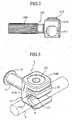
- a rod connector 1according to an embodiment of the present invention is provided with a shank portion 3 having a circular cross sectional shape and supported to a U-shaped engagement groove formed in an upper portion of a screw (an implant) S being screwed into a vertebra body (not shown).
- a rear end portion of the shank portion 3is provided with a flange portion 5 (a come-off prevention means) for preventing the rod connector 1 from coming off from the U-shaped engagement groove of the screw S in an axial direction.
- a connector main body 11is swingably attached to a distal end portion of the shank portion 3.
- the connector main body 11is provided with a rod supporting portion 9 having a circular arc curved shape and supporting a rod 7 for a bone connection connecting vertebra bodies.
- the connector main body 11is comprised of a base body portion 11A being vertically attached to the shank 3, protruding portions 11B and 11C extended from both upper and lower end sides of the base body portion 11A approximately, and has an approximately C shape.
- a rod supporting portion 9is formed on an opposing surface in which the protruding portion 11C opposes to the protruding portion 11B.
- a rod pressing member 15provided with a rod pressing portion 13 having a circular arc curved surface and opposing to the rod supporting portion 9 is attached to the connector main body 11 so as to freely move in a direction moving apart from and close to the rod supporting portion 9.
- a through hole 17 penetrating in a horizontal direction in Fig. 4is formed in the base body portion 11A, and a base portion 15A of the rod pressing member 15 is engaged within the through hole 17 so as to vertically move.
- a spherical body portion 19 formed in a distal end portion of the shank portion 3is attached to the through hole 17 .
- a pair of engagement recess portions 21, 21is formed in each of a portion in which the base body portion 11A of the connector main body 11 corresponds to the spherical body portion 19, and a portion in which the base portion 15A of the rod pressing member 15 corresponds to the spherical body portion 19 in an opposing manner.
- the spherical body portion 19is swingably attached to the pair of engagement recess portions 21, 21.
- a protruding portion 11Bis provided'with a pressure fixing device 23 for pressing and fixing the rod pressing member 15 in a direction of the rod supporting portion 9.
- a fixing screw freely pressing the rod pressing member 15 by a distal end thereofis screwed into the connector main body 11.
- the rod 7can be fixed and supported by the rod supporting portion 9 and the rod pressing portion 13, by fastening the fixing device (the pressure fixing screw) 23, and the connector main body 11 can be fixed to the shank portion 3.
- small convex portions 25 , 25 having a sharp distal end eating into the rod 7are provided in a protruding manner in both end sides of the rod supporting portion 9 and the rod pressing portion 13 (both end sides of the rod 7 in a longitudinal direction), as shown in Fig. 5B .
- a supporting surface 9ais provided between the convex portions 25, 25 of the rod supporting portion 9( Fig. 5B shows only the small convex portion 25 of the rod supporting portion 9).
- a supporting surface 13ais provided between the convex portions(not shown).
- These supporting surfaces 9a, 13aare formed as a rough surface, for example, by a sand blast or the like.
- the rod supporting portion 9is replaced by the connector main body 11 formed in the circular arc curved surface corresponding to the diameter of the rod 7, and the rod pressing portion 13 is replaced by the rod pressing member 15 formed in the circular arc curved surface corresponding to the diameter of the rod 7, whereby it is possible to simultaneously achieve a clamping and fixing of the rod 7 and a fixing and integrally forming of the connector main body 11 with respect to the spherical body portion 19 of the shank portion 3.
- it is possible to correspond to various rods 7 having various diametersby replacing both of the connector main body 11 and the rod pressing member 15 with respect to the shank portion 3.
- the rod connector of the present embodimentit is possible to adjust a position of the shank portion 3 in an axial direction with respect to the screw screwed into the vertebra body so as to fix, and it is possible to adjust swing and rotation of the connector main body 11 in a desired direction with respect to the shank portion 3 so as to fix.
Landscapes
- Health & Medical Sciences (AREA)
- Orthopedic Medicine & Surgery (AREA)
- Life Sciences & Earth Sciences (AREA)
- Surgery (AREA)
- Neurology (AREA)
- Heart & Thoracic Surgery (AREA)
- Engineering & Computer Science (AREA)
- Biomedical Technology (AREA)
- Nuclear Medicine, Radiotherapy & Molecular Imaging (AREA)
- Medical Informatics (AREA)
- Molecular Biology (AREA)
- Animal Behavior & Ethology (AREA)
- General Health & Medical Sciences (AREA)
- Public Health (AREA)
- Veterinary Medicine (AREA)
- Surgical Instruments (AREA)
- Prostheses (AREA)
Description
- The present invention relates to a rod connector according to the preamble of
claim 1. Such rod connector is used for supporting a bone connection rod which connects bones, for example, a breast bone, a lumbar vertebra or the like. More particularly, the invention relates to a rod connector structured such that a connector main body supporting the rod freely swings with respect to a shank portion attached to an implant, for example, a screw or the like. - A rod connector of the above type is known from the document
US-A-5,584,831 . A related device is known from the documentUS 668 546 A5 . - As shown in
Fig. 1 , in a conventional bone connecting method, a plurality of screws (implants) 103 is screwed in to a lumbar vertebrae, and eachscrews 103 is supported by arod 105 each other. And aconventional rod connector 107 interconnects thescrews 103 and therod 105. - As shown in
Fig. 2 , theconventional rod connector 107 is comprised of a connectormain body 113 integrally formed in a distal end of ashank portion 109 supported by a head portion of thescrew 103. The connectormain body 113 is provided with arod insertion hole 111 allowing to freely insert the rod 105 (shown inFig. 1 ) and alocking screw 115 for pressure fixing therod 105. - According to the structure mentioned above, even in the case that a position of the
screw 103 is slightly displaced, it is possible to fine adjust the position of therod connector 107 by adjusting a position of theshank portion 109 and a rotation of theshank portion 109 around an axis thereof with respect to thescrew 103, whereby it is possible to properly support therod 105. However, therod connector 107 can be adjusted with respect to thescrew 103 only in a range that theshank portion 109 can rotate. Accordingly, there is a problem that an adjustable range is small. - Further, according to
Japanese Patent Application Laid-Open No. 11-318932 rod connector 107 of the related art mentioned-above is constituted by a plastically deformable member, and a rod is properly supported by plastically deforming the connection device. - In this case, there is also a problem that a freedom of adjusting the rod connector with respect to the screw is small.
- The present invention is made by taking the problems mentioned above into consideration, and an object of the present invention is to provide a rod connector in which a position adjustable range is large. To attain this object, a rod connector according to the present invention comprises the features of
claim 1. - Preferred embodiments are claimed in the subclaims.
Fig. 1 is a schematic view showing a connection state of a vertebra body by using a conventional rod;Fig. 2 is a schematic view of a conventional rod connector;Fig. 3 is a perspective view of a rod connector according to an embodiment of the present invention;Fig. 4 is a front elevation view of the rod connector according to the embodiment of the present invention;Fig. 5A is a right side view of the rod connector according to the embodiment of the present invention;Fig. 5B is a partly enlarged view ofFig. 5A ; andFig. 6 is a plan view of the rod connector according to the embodiment of the present invention.- With reference to
Figs. 3 and4 , arod connector 1 according to an embodiment of the present invention is provided with ashank portion 3 having a circular cross sectional shape and supported to a U-shaped engagement groove formed in an upper portion of a screw (an implant) S being screwed into a vertebra body (not shown). A rear end portion of theshank portion 3 is provided with a flange portion 5 (a come-off prevention means) for preventing therod connector 1 from coming off from the U-shaped engagement groove of the screw S in an axial direction. - A connector
main body 11 is swingably attached to a distal end portion of theshank portion 3. The connectormain body 11 is provided with arod supporting portion 9 having a circular arc curved shape and supporting a rod 7 for a bone connection connecting vertebra bodies. In more detail, the connectormain body 11 is comprised of abase body portion 11A being vertically attached to theshank 3, protrudingportions base body portion 11A approximately, and has an approximately C shape. Further, arod supporting portion 9 is formed on an opposing surface in which the protrudingportion 11C opposes to the protrudingportion 11B. - In order to pressure fix the rod 7 to the
rod supporting portion 9 , arod pressing member 15 provided with arod pressing portion 13 having a circular arc curved surface and opposing to therod supporting portion 9 is attached to the connectormain body 11 so as to freely move in a direction moving apart from and close to therod supporting portion 9. - In more detail, a
through hole 17 penetrating in a horizontal direction inFig. 4 is formed in thebase body portion 11A, and abase portion 15A of therod pressing member 15 is engaged within the throughhole 17 so as to vertically move. Further, aspherical body portion 19 formed in a distal end portion of theshank portion 3 is attached to the throughhole 17 . Further, a pair of engagement recessportions base body portion 11A of the connectormain body 11 corresponds to thespherical body portion 19, and a portion in which thebase portion 15A of therod pressing member 15 corresponds to thespherical body portion 19 in an opposing manner. Thespherical body portion 19 is swingably attached to the pair of engagement recessportions - Accordingly, in a state in which the
spherical body portion 19 of theshank portion 3 is lightly clamped by the pair of engagement recessportions main body 11, it is possible to swing the connectormain body 11 in a desired direction with respect to theshank portion 3. On the other hand, when the pair of engagement recessportions spherical portion 19, the connectormain body 11 is fixed to theshank portion 3. - In order to clamp and fix the rod 7 by the
rod supporting portion 9 and therod pressing portion 13, and clamp and fix thespherical body portion 19 by the pair of engagement recessportions portion 11B is provided'with apressure fixing device 23 for pressing and fixing therod pressing member 15 in a direction of therod supporting portion 9. As one embodiment of thepressure fixing device 23, in the present embodiment, a fixing screw freely pressing therod pressing member 15 by a distal end thereof is screwed into the connectormain body 11. - Accordingly, the rod 7 can be fixed and supported by the
rod supporting portion 9 and therod pressing portion 13, by fastening the fixing device (the pressure fixing screw) 23, and the connectormain body 11 can be fixed to theshank portion 3. - In order to fix and support the rod 7, small
convex portions rod supporting portion 9 and the rod pressing portion 13 (both end sides of the rod 7 in a longitudinal direction), as shown inFig. 5B . Further, a supportingsurface 9a is provided between theconvex portions Fig. 5B shows only thesmall convex portion 25 of the rod supporting portion 9). In the same manner as the supportingsurface 9a, a supportingsurface 13a is provided between the convex portions(not shown). These supportingsurfaces - Accordingly, when the rod 7 is firmly clamped and gripped by the
rod supporting portion 9 and therod pressing portion 13, and a stress is concentrated near a distal end by the sharp distal end of the smallconvex portions 25, so that the distal end of theconvex portions 25 eats into the surface of the rod 7 so as to generate a scratch, and the supportingsurface 9a(13a) of the rough surface is brought into contact with the rod 7. Therefore, it is possible to prevent the rod 7 from moving in the axial direction and it is possible to prevent the rod 7 from rotating around an axis thereof. - In this case, in some difference in diameter of the rod 7, there is a case that the engagement state between the engagement recess
portions main body 11 and therod pressing member 15, and thespherical body portion 19 of theshank portion 3 is slack, at a time of firmly gripping and fixing the rod 7 by therod supporting portion 9 and therod pressing portion 13 . Further, on the contrary, there is a case that the clamping and fixing state of the rod 7 by therod supporting portion 9 and therod pressing portion 13 becomes slack, in a state in which the engagement state between both the engagement recessportions 21 and thespherical body portion 19 is a firm fixing state. - In the case mentioned above, the
rod supporting portion 9 is replaced by the connectormain body 11 formed in the circular arc curved surface corresponding to the diameter of the rod 7, and therod pressing portion 13 is replaced by therod pressing member 15 formed in the circular arc curved surface corresponding to the diameter of the rod 7, whereby it is possible to simultaneously achieve a clamping and fixing of the rod 7 and a fixing and integrally forming of the connectormain body 11 with respect to thespherical body portion 19 of theshank portion 3. In other words, it is possible to correspond to various rods 7 having various diameters by replacing both of the connectormain body 11 and therod pressing member 15 with respect to theshank portion 3. - According to the rod connector of the present embodiment, it is possible to adjust a position of the
shank portion 3 in an axial direction with respect to the screw screwed into the vertebra body so as to fix, and it is possible to adjust swing and rotation of the connectormain body 11 in a desired direction with respect to theshank portion 3 so as to fix. - Accordingly, even in the case that an adjusting freedom of the rod connector is large with respect to the screw screwed and fixed to the vertebra and a slight displacement is generated in the screw fixing position, or even in the case that the rod 7 has a curve, an incline or the like, it is possible to easily correspond thereto, and it is possible to always property support and fix the rod 7, so that the conventional problems mentioned above can be solved.
Claims (5)
- A rod connector (1) comprising:a connector main body (11) attached to one end of a shank portion (3) such that the connector main body (11) is swingably attached to the shank portion (3) in a first state and is fixed to the shank portion (3) in a second state;a rod supporting portion (9) provided with the connector main body (11) and configured for supporting a rod (7); anda rod pressing member (15) provided with a rod pressing portion (13) opposing to the rod supporting portion (9); anda pressure fixing device for pressure fixing the rod (7) to the rod supporting portion (9) of the connector main body (11) via the rod pressing member (15),wherein the rod pressing member (15) is engaged with the connector main body (11) so as to freely move in a direction moving apart from and dose to the rod supporting portion (9), wherein
said connector main body (11) approximately has a C shape and comprises a base body portion (11 A) attached to the shank (3) and two protruding portions (11B, 11 C) extending from both upper and lower end sides of the base body portion (11A),
wherein the rod supporting portion (9) is formed on a surface of a first one (11C) of said two protruding portions (11B, 11C) opposing a second one (11 B) of said two protruding portions (11B, 11C),characterized in that a through hole (17) is formed in the base body portion (11A), and a base portion (15A) of the rod pressing member (15) is engaged within the through hole (17) so as to move therein. - The rod connector of claim 1,characterized in that a convex portion (25) having a sharp distal end eating into the rod (7) is provided in both end sides of at least one of the rod supporting portion (9) and the rod pressing portion (13).
- The rod connector of claim 1 or 2,characterized in that a supporting surface (9a) of the rod supporting portion (9) is formed in a rough surface.
- The rod connector of claim 1 or 2,characterized in that engagement recess portions (21) respectively formed in the connector main body (11) and the rod pressing member (15) are engaged with a spherical body portion (19) formedin that end of the shank portion (3) which is attached to the connector main body (11).
- The rod connector of claim 1 or 2,characterized in that a flange portion (5) for come-off prevention is provided to that end of the shank portion (3) which is opposed to the end attached to the connector main body (11).
Applications Claiming Priority (2)
| Application Number | Priority Date | Filing Date | Title |
|---|---|---|---|
| JP2002267299 | 2002-09-12 | ||
| JP2002267299AJP4047113B2 (en) | 2002-09-12 | 2002-09-12 | Rod connector |
Publications (2)
| Publication Number | Publication Date |
|---|---|
| EP1397999A1 EP1397999A1 (en) | 2004-03-17 |
| EP1397999B1true EP1397999B1 (en) | 2009-04-29 |
Family
ID=31884800
Family Applications (1)
| Application Number | Title | Priority Date | Filing Date |
|---|---|---|---|
| EP03020810AExpired - LifetimeEP1397999B1 (en) | 2002-09-12 | 2003-09-12 | Rod connector |
Country Status (5)
| Country | Link |
|---|---|
| US (2) | US7572278B2 (en) |
| EP (1) | EP1397999B1 (en) |
| JP (1) | JP4047113B2 (en) |
| KR (1) | KR100617378B1 (en) |
| DE (1) | DE60327397D1 (en) |
Families Citing this family (32)
| Publication number | Priority date | Publication date | Assignee | Title |
|---|---|---|---|---|
| KR100542217B1 (en)* | 2004-06-07 | 2006-01-12 | 삼성에스디아이 주식회사 | Fuel cell system and reformer used therein |
| KR100551053B1 (en)* | 2004-06-29 | 2006-02-09 | 삼성에스디아이 주식회사 | Reformer of fuel cell system and fuel cell system employing same |
| US7959653B2 (en)* | 2004-09-03 | 2011-06-14 | Lanx, Inc. | Spinal rod cross connector |
| US20070225713A1 (en)* | 2004-10-20 | 2007-09-27 | Moti Altarac | Systems and methods for posterior dynamic stabilization of the spine |
| US7708762B2 (en)* | 2005-04-08 | 2010-05-04 | Warsaw Orthopedic, Inc. | Systems, devices and methods for stabilization of the spinal column |
| US7628799B2 (en) | 2005-08-23 | 2009-12-08 | Aesculap Ag & Co. Kg | Rod to rod connector |
| US20080021456A1 (en)* | 2006-07-21 | 2008-01-24 | Depuy Spine, Inc. | Sacral or iliac cross connector |
| US20080021455A1 (en)* | 2006-07-21 | 2008-01-24 | Depuy Spine, Inc. | Articulating Sacral or Iliac Connector |
| US7744632B2 (en) | 2006-12-20 | 2010-06-29 | Aesculap Implant Systems, Inc. | Rod to rod connector |
| US7789895B2 (en)* | 2006-12-26 | 2010-09-07 | Warsaw Orthopedic, Inc. | Sacral reconstruction fixation device |
| JP2009207877A (en)* | 2008-02-07 | 2009-09-17 | Showa Ika Kohgyo Co Ltd | Rod connector |
| EP2249725B1 (en)* | 2009-02-19 | 2015-06-10 | Ulrich GmbH & Co. KG | Device for stabilizing the spinal column |
| US8998961B1 (en) | 2009-02-26 | 2015-04-07 | Lanx, Inc. | Spinal rod connector and methods |
| US8091305B2 (en)* | 2009-02-27 | 2012-01-10 | Skeeter Jane A | Recycled glass structural and decorative barrier or building, lighting and furniture component |
| EP2421454A4 (en)* | 2009-04-23 | 2013-12-11 | Spinal Elements Inc | Transverse connectors |
| US9381044B2 (en) | 2010-01-26 | 2016-07-05 | Pioneer Surgical Technology, Inc. | Posterior spinal stabilization plate device |
| US9050138B2 (en) | 2010-01-28 | 2015-06-09 | Warsaw Orthopedic, Inc. | Vertebral rod connector and methods of use |
| US8672978B2 (en) | 2011-03-04 | 2014-03-18 | Zimmer Spine, Inc. | Transverse connector |
| US9339305B2 (en) | 2011-09-19 | 2016-05-17 | DePuy Synthes Products, Inc. | Snap fit rod and fastener system |
| US8758411B1 (en) | 2011-10-25 | 2014-06-24 | Nuvasive, Inc. | Implants and methods for treating spinal disorders |
| US9101405B2 (en)* | 2012-02-10 | 2015-08-11 | Warsaw Orthopedic, Inc. | Vertebral implant and connector |
| US8940020B2 (en) | 2012-04-06 | 2015-01-27 | DePuy Synthes Products, LLC | Rod connector |
| US8771319B2 (en) | 2012-04-16 | 2014-07-08 | Aesculap Implant Systems, Llc | Rod to rod cross connector |
| US8828056B2 (en) | 2012-04-16 | 2014-09-09 | Aesculap Implant Systems, Llc | Rod to rod cross connector |
| US9072547B2 (en) | 2012-11-06 | 2015-07-07 | Globus Medical, Inc. | Polyaxial cross connector |
| US9737340B1 (en) | 2014-09-16 | 2017-08-22 | Nuvasive, Inc. | Adjustable iliac connector |
| US10575876B2 (en) | 2016-04-20 | 2020-03-03 | K2M, Inc. | Spinal stabilization assemblies with bone hooks |
| KR101934250B1 (en)* | 2017-01-06 | 2019-01-02 | 주식회사 코렌텍 | Spinal fixation rod connector |
| JP7217891B2 (en)* | 2017-12-15 | 2023-02-06 | ミズホ株式会社 | spinal fixation system |
| JP7506387B2 (en)* | 2019-11-26 | 2024-06-26 | 帝人ナカシマメディカル株式会社 | Spinal Fusion Connectors and Spinal Fusion Implants |
| US11426211B2 (en)* | 2020-10-28 | 2022-08-30 | Globus Medical, Inc. | Articulating connectors, systems, and methods thereof |
| US12114899B2 (en) | 2022-06-23 | 2024-10-15 | Warsaw Orthopedic, Inc. | Spinal implant and method |
Family Cites Families (25)
| Publication number | Priority date | Publication date | Assignee | Title |
|---|---|---|---|---|
| US4611582A (en)* | 1983-12-27 | 1986-09-16 | Wisconsin Alumni Research Foundation | Vertebral clamp |
| IL80661A (en) | 1985-11-29 | 1991-07-18 | Jaquet Orthopedie | Device for positioning and securing a part having circular regions |
| CH668546A5 (en) | 1986-09-29 | 1989-01-13 | Jaquet Orthopedie | Clamp for bone fixture |
| US5002542A (en) | 1989-10-30 | 1991-03-26 | Synthes U.S.A. | Pedicle screw clamp |
| US5254118A (en)* | 1991-12-04 | 1993-10-19 | Srdjian Mirkovic | Three dimensional spine fixation system |
| FR2697992B1 (en)* | 1992-11-18 | 1994-12-30 | Eurosurgical | Device for attaching to a rod of an organ, in particular for spinal orthopedic instrumentation. |
| US5584831A (en)* | 1993-07-09 | 1996-12-17 | September 28, Inc. | Spinal fixation device and method |
| US5474551A (en)* | 1994-11-18 | 1995-12-12 | Smith & Nephew Richards, Inc. | Universal coupler for spinal fixation |
| FR2731344B1 (en)* | 1995-03-06 | 1997-08-22 | Dimso Sa | SPINAL INSTRUMENTATION ESPECIALLY FOR A ROD |
| US5716355A (en)* | 1995-04-10 | 1998-02-10 | Sofamor Danek Group, Inc. | Transverse connection for spinal rods |
| US5545167A (en) | 1995-04-11 | 1996-08-13 | Lin; Chih-I | Retaining mechanism of vertebral fixation rod |
| JP3090588B2 (en)* | 1995-05-12 | 2000-09-25 | 株式会社ソミック石川 | Ball joint |
| US5575792A (en)* | 1995-07-14 | 1996-11-19 | Fastenetix, L.L.C. | Extending hook and polyaxial coupling element device for use with top loading rod fixation devices |
| JP2871620B2 (en)* | 1996-09-06 | 1999-03-17 | 株式会社ロバート・リード商会 | Bone fixation device |
| US5776135A (en)* | 1996-12-23 | 1998-07-07 | Third Millennium Engineering, Llc | Side mounted polyaxial pedicle screw |
| FR2759894B1 (en) | 1997-02-24 | 1999-03-26 | Khalil Kharrat | OFFSET CHANNEL IMPLANT FOR INTERVERTEBRAL OSTEOSYNTHESIS IN PARTICULAR WITH CATCHING HOOK |
| FR2761590B1 (en)* | 1997-04-04 | 1999-08-20 | Stryker France Sa | DEVICE FOR OSTEOSYNTHESIS OF THE RACHIS WITH ATTACHMENT OF DEAXED INTERVERTEBRAL ROD |
| US6016592A (en)* | 1998-03-17 | 2000-01-25 | Aeroquip Corporation | Pipe coupling tool |
| FR2776915B1 (en) | 1998-04-03 | 2000-06-30 | Eurosurgical | SPINAL OSTEOSYNTHESIS DEVICE ADAPTABLE TO DIFFERENCES IN ALIGNMENT, ANGULATION AND DRIVING OF PEDICULAR SCREWS |
| US6264658B1 (en)* | 1998-07-06 | 2001-07-24 | Solco Surgical Instruments Co., Ltd. | Spine fixing apparatus |
| WO2000015125A1 (en)* | 1998-09-11 | 2000-03-23 | Synthes Ag Chur | Variable angle spinal fixation system |
| DE19957332B4 (en)* | 1999-11-29 | 2004-11-11 | Bernd Schäfer | cross-connector |
| US6616668B2 (en)* | 2000-06-09 | 2003-09-09 | Cross Medical Products, Inc. | Adjustable transverse connector for use with a spinal implant system |
| US20030114853A1 (en)* | 2001-10-12 | 2003-06-19 | Ian Burgess | Polyaxial cross connector |
| US7066938B2 (en)* | 2002-09-09 | 2006-06-27 | Depuy Spine, Inc. | Snap-on spinal rod connector |
- 2002
- 2002-09-12JPJP2002267299Apatent/JP4047113B2/ennot_activeExpired - Lifetime
- 2003
- 2003-09-08KRKR1020030062794Apatent/KR100617378B1/ennot_activeExpired - Fee Related
- 2003-09-11USUS10/659,297patent/US7572278B2/ennot_activeExpired - Fee Related
- 2003-09-12EPEP03020810Apatent/EP1397999B1/ennot_activeExpired - Lifetime
- 2003-09-12DEDE60327397Tpatent/DE60327397D1/ennot_activeExpired - Lifetime
- 2006
- 2006-01-06USUS11/326,412patent/US7569070B2/ennot_activeExpired - Fee Related
Also Published As
| Publication number | Publication date |
|---|---|
| DE60327397D1 (en) | 2009-06-10 |
| US20060129150A1 (en) | 2006-06-15 |
| US7572278B2 (en) | 2009-08-11 |
| US20040133202A1 (en) | 2004-07-08 |
| KR100617378B1 (en) | 2006-08-29 |
| KR20040024493A (en) | 2004-03-20 |
| JP4047113B2 (en) | 2008-02-13 |
| US7569070B2 (en) | 2009-08-04 |
| JP2004097706A (en) | 2004-04-02 |
| EP1397999A1 (en) | 2004-03-17 |
Similar Documents
| Publication | Publication Date | Title |
|---|---|---|
| EP1397999B1 (en) | Rod connector | |
| EP2070485B1 (en) | Anchoring device for anchoring a rod in bones or vertebrae | |
| EP1778108B1 (en) | Orthopedic fixation systems for attaching elongated members | |
| EP2174609B1 (en) | Spinal Rod Connector | |
| US6860884B2 (en) | Implant for bone connector | |
| US6524310B1 (en) | Surgical cross-connecting apparatus having locking lever | |
| US11690654B2 (en) | Adjustable fixation device | |
| EP1098601B1 (en) | Spinal osteosynthesis device | |
| CN1298294C (en) | Spinal osteosynthesis device and preparation method | |
| EP2410934B1 (en) | Spine fixation system | |
| US6682529B2 (en) | Connector assembly with multidimensional accommodation and associated method | |
| US8262700B2 (en) | Transverse spinal linking device and system | |
| US5562661A (en) | Top tightening bone fixation apparatus | |
| US9138264B2 (en) | Laminoplasty rod system | |
| JPH1043202A (en) | Bone fixing device for fixing to sacrum during backbone jointing operation | |
| AU2001285096A1 (en) | A surgical cross-connecting apparatus | |
| US20090062822A1 (en) | Adaptable clamping mechanism for coupling a spinal fixation element to a bone anchor | |
| EP3656321B1 (en) | Occipital plate with angled screw opening | |
| EP3943028B1 (en) | Rod system including at least two rods and connector device for rods |
Legal Events
| Date | Code | Title | Description |
|---|---|---|---|
| PUAI | Public reference made under article 153(3) epc to a published international application that has entered the european phase | Free format text:ORIGINAL CODE: 0009012 | |
| 17P | Request for examination filed | Effective date:20030912 | |
| AK | Designated contracting states | Kind code of ref document:A1 Designated state(s):AT BE BG CH CY CZ DE DK EE ES FI FR GB GR HU IE IT LI LU MC NL PT RO SE SI SK TR | |
| AX | Request for extension of the european patent | Extension state:AL LT LV MK | |
| RIN1 | Information on inventor provided before grant (corrected) | Inventor name:TAKAMIDO, HIROSHI C/O SHOWA IKA KOHGYO CO.LTD. Inventor name:SUZUKI, NOBUMASA Inventor name:SATO, SHIGENOBU Inventor name:HASEGAWA, KAZUHIRO Inventor name:UEYAMA, KAZUMASA Inventor name:ORIBE, KAZUYA C/O SHOWA IKA KOHGYO CO.LTD. Inventor name:NAKAHARA, SHINNOSUKE Inventor name:NOHARA, YUTAKA | |
| AKX | Designation fees paid | Designated state(s):DE FR | |
| 17Q | First examination report despatched | Effective date:20070103 | |
| GRAP | Despatch of communication of intention to grant a patent | Free format text:ORIGINAL CODE: EPIDOSNIGR1 | |
| RIN1 | Information on inventor provided before grant (corrected) | Inventor name:SATO, SHIGENOBU Inventor name:TAKAMIDO, HIROSHI Inventor name:HASEGAWA, KAZUHIRO Inventor name:UEYAMA, KAZUMASA Inventor name:NOHARA, YUTAKA Inventor name:NAKAHARA, SHINNOSUKE Inventor name:ORIBE, KAZUYA Inventor name:SUZUKI, NOBUMASA | |
| GRAS | Grant fee paid | Free format text:ORIGINAL CODE: EPIDOSNIGR3 | |
| GRAA | (expected) grant | Free format text:ORIGINAL CODE: 0009210 | |
| AK | Designated contracting states | Kind code of ref document:B1 Designated state(s):DE FR | |
| REF | Corresponds to: | Ref document number:60327397 Country of ref document:DE Date of ref document:20090610 Kind code of ref document:P | |
| PLBE | No opposition filed within time limit | Free format text:ORIGINAL CODE: 0009261 | |
| STAA | Information on the status of an ep patent application or granted ep patent | Free format text:STATUS: NO OPPOSITION FILED WITHIN TIME LIMIT | |
| 26N | No opposition filed | Effective date:20100201 | |
| PGFP | Annual fee paid to national office [announced via postgrant information from national office to epo] | Ref country code:FR Payment date:20121011 Year of fee payment:10 Ref country code:DE Payment date:20120927 Year of fee payment:10 | |
| REG | Reference to a national code | Ref country code:DE Ref legal event code:R119 Ref document number:60327397 Country of ref document:DE Effective date:20140401 | |
| REG | Reference to a national code | Ref country code:FR Ref legal event code:ST Effective date:20140530 | |
| PG25 | Lapsed in a contracting state [announced via postgrant information from national office to epo] | Ref country code:DE Free format text:LAPSE BECAUSE OF NON-PAYMENT OF DUE FEES Effective date:20140401 Ref country code:FR Free format text:LAPSE BECAUSE OF NON-PAYMENT OF DUE FEES Effective date:20130930 |