EP1396243A1 - Surgical ring with remote control system for reversible variation of diameter - Google Patents
Surgical ring with remote control system for reversible variation of diameterDownload PDFInfo
- Publication number
- EP1396243A1 EP1396243A1EP02019937AEP02019937AEP1396243A1EP 1396243 A1EP1396243 A1EP 1396243A1EP 02019937 AEP02019937 AEP 02019937AEP 02019937 AEP02019937 AEP 02019937AEP 1396243 A1EP1396243 A1EP 1396243A1
- Authority
- EP
- European Patent Office
- Prior art keywords
- ring
- ring according
- diameter
- actuator
- patient
- Prior art date
- Legal status (The legal status is an assumption and is not a legal conclusion. Google has not performed a legal analysis and makes no representation as to the accuracy of the status listed.)
- Granted
Links
- 230000002441reversible effectEffects0.000titleclaimsdescription7
- 239000000463materialSubstances0.000claimsabstractdescription15
- 230000002496gastric effectEffects0.000claimsdescription37
- 210000002784stomachAnatomy0.000claimsdescription15
- 230000037406food intakeEffects0.000claimsdescription6
- 210000000056organAnatomy0.000claimsdescription5
- 229920001296polysiloxanePolymers0.000claimsdescription4
- 238000013519translationMethods0.000claimsdescription4
- 210000004204blood vesselAnatomy0.000claimsdescription3
- 229920000295expanded polytetrafluoroethylenePolymers0.000claimsdescription3
- 210000001035gastrointestinal tractAnatomy0.000claimsdescription3
- 239000002861polymer materialSubstances0.000claimsdescription3
- 210000003238esophagusAnatomy0.000claimsdescription2
- 239000011253protective coatingSubstances0.000claimsdescription2
- 210000001635urinary tractAnatomy0.000claimsdescription2
- 230000002787reinforcementEffects0.000claims1
- 239000007943implantSubstances0.000abstractdescription5
- 238000001356surgical procedureMethods0.000description10
- 238000000034methodMethods0.000description7
- 208000008589ObesityDiseases0.000description4
- 239000012530fluidSubstances0.000description4
- 238000009434installationMethods0.000description4
- 208000001022morbid obesityDiseases0.000description4
- 238000011282treatmentMethods0.000description4
- 208000034347Faecal incontinenceDiseases0.000description3
- 206010046543Urinary incontinenceDiseases0.000description3
- 230000008859changeEffects0.000description3
- 230000006835compressionEffects0.000description3
- 238000007906compressionMethods0.000description3
- 208000012696congenital leptin deficiencyDiseases0.000description3
- 238000010521absorption reactionMethods0.000description2
- 230000009471actionEffects0.000description2
- 230000008901benefitEffects0.000description2
- 230000005540biological transmissionEffects0.000description2
- 230000017531blood circulationEffects0.000description2
- 230000000295complement effectEffects0.000description2
- 238000005520cutting processMethods0.000description2
- 230000001079digestive effectEffects0.000description2
- 238000006073displacement reactionMethods0.000description2
- 235000012631food intakeNutrition0.000description2
- 235000011389fruit/vegetable juiceNutrition0.000description2
- 230000036541healthEffects0.000description2
- 238000002513implantationMethods0.000description2
- 230000009467reductionEffects0.000description2
- 238000007789sealingMethods0.000description2
- 238000007920subcutaneous administrationMethods0.000description2
- 238000011477surgical interventionMethods0.000description2
- 230000002485urinary effectEffects0.000description2
- 208000024172Cardiovascular diseaseDiseases0.000description1
- 101100536354Drosophila melanogaster tant geneProteins0.000description1
- 206010020772HypertensionDiseases0.000description1
- 206010061218InflammationDiseases0.000description1
- 206010033307OverweightDiseases0.000description1
- 206010047700VomitingDiseases0.000description1
- 206010003246arthritisDiseases0.000description1
- 230000009286beneficial effectEffects0.000description1
- 239000011248coating agentSubstances0.000description1
- 238000000576coating methodMethods0.000description1
- 238000007796conventional methodMethods0.000description1
- 230000006378damageEffects0.000description1
- 230000007547defectEffects0.000description1
- 238000011161developmentMethods0.000description1
- 206010012601diabetes mellitusDiseases0.000description1
- 235000005911dietNutrition0.000description1
- 230000037213dietEffects0.000description1
- 201000010099diseaseDiseases0.000description1
- 208000037265diseases, disorders, signs and symptomsDiseases0.000description1
- 238000009826distributionMethods0.000description1
- 229920001971elastomerPolymers0.000description1
- 239000000806elastomerSubstances0.000description1
- 239000013536elastomeric materialSubstances0.000description1
- 239000003292glueSubstances0.000description1
- 208000015181infectious diseaseDiseases0.000description1
- 230000004054inflammatory processEffects0.000description1
- 238000002347injectionMethods0.000description1
- 239000007924injectionSubstances0.000description1
- 238000003780insertionMethods0.000description1
- 230000037431insertionEffects0.000description1
- 238000012977invasive surgical procedureMethods0.000description1
- 238000005304joiningMethods0.000description1
- 239000007788liquidSubstances0.000description1
- 238000011866long-term treatmentMethods0.000description1
- 238000012986modificationMethods0.000description1
- 230000004048modificationEffects0.000description1
- 238000012544monitoring processMethods0.000description1
- 235000020824obesityNutrition0.000description1
- 230000000750progressive effectEffects0.000description1
- 230000001681protective effectEffects0.000description1
- 230000003014reinforcing effectEffects0.000description1
- 238000000926separation methodMethods0.000description1
- 238000004904shorteningMethods0.000description1
- 239000002356single layerSubstances0.000description1
- 210000000813small intestineAnatomy0.000description1
- 210000005070sphincterAnatomy0.000description1
- 230000001225therapeutic effectEffects0.000description1
- 238000012549trainingMethods0.000description1
- 230000008673vomitingEffects0.000description1
- XLYOFNOQVPJJNP-UHFFFAOYSA-NwaterSubstancesOXLYOFNOQVPJJNP-UHFFFAOYSA-N0.000description1
Images


Classifications
- A—HUMAN NECESSITIES
- A61—MEDICAL OR VETERINARY SCIENCE; HYGIENE
- A61F—FILTERS IMPLANTABLE INTO BLOOD VESSELS; PROSTHESES; DEVICES PROVIDING PATENCY TO, OR PREVENTING COLLAPSING OF, TUBULAR STRUCTURES OF THE BODY, e.g. STENTS; ORTHOPAEDIC, NURSING OR CONTRACEPTIVE DEVICES; FOMENTATION; TREATMENT OR PROTECTION OF EYES OR EARS; BANDAGES, DRESSINGS OR ABSORBENT PADS; FIRST-AID KITS
- A61F5/00—Orthopaedic methods or devices for non-surgical treatment of bones or joints; Nursing devices ; Anti-rape devices
- A61F5/0003—Apparatus for the treatment of obesity; Anti-eating devices
- A61F5/0013—Implantable devices or invasive measures
- A61F5/005—Gastric bands
- A61F5/0066—Closing devices for gastric bands
- A—HUMAN NECESSITIES
- A61—MEDICAL OR VETERINARY SCIENCE; HYGIENE
- A61F—FILTERS IMPLANTABLE INTO BLOOD VESSELS; PROSTHESES; DEVICES PROVIDING PATENCY TO, OR PREVENTING COLLAPSING OF, TUBULAR STRUCTURES OF THE BODY, e.g. STENTS; ORTHOPAEDIC, NURSING OR CONTRACEPTIVE DEVICES; FOMENTATION; TREATMENT OR PROTECTION OF EYES OR EARS; BANDAGES, DRESSINGS OR ABSORBENT PADS; FIRST-AID KITS
- A61F5/00—Orthopaedic methods or devices for non-surgical treatment of bones or joints; Nursing devices ; Anti-rape devices
- A61F5/0003—Apparatus for the treatment of obesity; Anti-eating devices
- A61F5/0013—Implantable devices or invasive measures
- A61F5/005—Gastric bands
- A61F5/0053—Gastric bands remotely adjustable
Definitions
- the present inventionrelates to the technical field of implants intended to be implanted in the body of a patient around biological organs that make up a pocket or conduit, and more particularly gastric bands designed to treat obesity by implantation of a flexible gastric band, intended to form a loop closed around the stomach to reduce the diameter of the opening of the stoma, the invention relating more particularly to gastroplasty rings remotely controlled, involving no invasive operation after its installation.
- the present inventionrelates to a surgical ring intended to be implanted in the body of a patient around biological organs constituting a pocket or conduit for, on the one hand forming a closed loop between its two ends thus forming respectively a first and a second end and, on the other hand, reduce the diameter of the opening of said member when enclosed by the ring, said ring comprising a system for precisely and reversibly control the variation of the diameter of the ring.
- the inventionrelates more particularly to a gastroplasty ring, but it can also relate to a ring designed to be used to treat urinary or fecal incontinence (artificial sphincter) or a ring designed to regulate blood flow to blood vessels by example, this list is by no means exhaustive.
- the present inventionrelates more particularly to a ring of remotely controlled gastroplasty thus avoiding any re-intervention invasive surgical adjustment of the diameter of the ring, said ring being then integrated into a restriction and remote control system of ingestion of food in the stomach of a patient, having a ring gastric system provided with an actuator connected to a receiving antenna for receive a control signal, as well as a transmitting antenna arranged at outside the patient to send a command signal to the antenna reception, then to the actuator.
- the ring according to the inventionis controlled by radio frequency, the actuator being on the one hand connected to the antenna reception by a reception circuit in which said antenna is integrated and secondly, comprising an electrical control box connected to the transmitting antenna.
- Surgical techniques involving a defect in absorptionare those involving, for example, a " bypass " technique or bypass of the small intestine, or those using separation of the passage of food relative to the digestive juices. These surgical techniques are relatively cumbersome and can lead to severe complications, which is why they are hardly used anymore.
- a flexible strip of elastomeric materialintended to be implanted around the stomach, forming a closed loop defining a fixed pre-established diameter of the ring thanks to a closing system.
- the body of the flexible striphas a cavity or compression chamber variable volume, which is connected to an adjustment catheter for injecting or to withdraw a fluid in the compression chamber, so as to make vary the internal diameter of the loop to modify or adjust the diameter of the stoma. So, in combination with the fixed and pre-established diameter of the ring, the diameter of the ring can be adjusted in a small proportion, which allows to regulate the diameter of the stoma and thus to regulate the quantity ingested food.
- Such a deviceobviously marks an interesting development and beneficial for patients but nevertheless suffers from a number disadvantages linked in particular to the need to implant in the body even from the patient a fluid reservoir, the implantation of which is delicate and whose sealing is difficult to achieve, which can represent a danger for the patient. Furthermore, such a device requires a power source internal, for example a battery, implanted in the patient's own body, this which again complicates the surgical intervention and above all gives a certain general fragility to the system, and may require a surgery to change the battery.
- a power source internalfor example a battery
- the inventiontherefore aims to remedy the various disadvantages listed above, and to propose a new ring with a reversible control system for the variation of its diameter, which is particularly simple, safe and effective, especially in matter of precision and performance, so that it can be integrated in a remote control system that does not require energy important order.
- Another object of the inventionaims to propose a new surgical ring, especially gastric whose mechanical control is particularly precise.
- Another object of the inventionaims to propose a new surgical ring, in particular gastric, likely to have a circular shape in use, while providing great control security.
- Another object of the inventionaims to propose a new surgical ring, in particular gastric allowing to implement means particularly proven and resistant mechanical, so as to obtain a gastric band of great robustness and good longevity.
- Another object of the inventionaims to propose a new surgical ring, especially gastric which, while allowing good control of the variation in the diameter of the ring, is likely to minimize phenomena of intolerance by the patient.
- Another object of the inventionaims to propose a new surgical ring, especially gastric whose control system is particularly economical in terms of energy used.
- Another object of the inventionis to propose a new gastric band particularly compact, allowing easy installation in the patient's stomach.
- Another object of the inventionaims to propose a new surgical ring, particularly gastric which allows a good distribution of all efforts to close the ring on the stomach.
- Another object of the inventionaims to propose a new system of restriction and remote control of food intake in the stomach a patient who is particularly efficient, very robust and good longevity, while requiring power supply relatively weak.
- a surgical ringintended to be implanted in the body of a patient around biological organs constituting a pocket or a conduit for, on the one hand forming a loop closed between its two ends thus forming a first and a second ends and on the other hand reduce the diameter of the opening of the biological organ when it is enclosed by the ring
- said ringcomprising a system for reversibly controlling the variation of its diameter, characterized in that said system comprises an element flexible filiform inserted longitudinally and sliding in the material forming the body of the ring substantially between the first and second ends, to define a fixed portion secured to the first end and a free portion functionally associated with an actuator mounted on the ring towards the second end, so that the actuator can ensure the reversible translation of the flexible element filiform to obtain an associated variation in the diameter of the ring.
- a gastric banddesigned to be implanted around stomach to reduce the diameter of the stoma opening, or around the esophagus.
- the inventionis in no way limited to this application and rather aims to cover other surgical rings, such as those used to treat urinary or fecal incontinence or those used around blood vessels to regulate blood flow.
- the ringIn the case of urinary incontinence treatment, the ring will be implanted around the bladder or urinary tract, and in the case of incontinence faecal, it will be implanted around the gastrointestinal tract, and in particular around the anal structures of the gut.
- Figures 1 to 10illustrate a gastric band according to the invention intended to be implanted around the stomach of a patient by forming a substantially circular loop, in order to achieve gastric restriction in reducing the diameter of the stoma opening.
- the conforming gastric band to the inventionis in the form of a flexible tubular strip, of which the flexible and elastic envelope has a smooth surface to make it atraumatic so as to be easily supported by the patient and stomach tissue.
- the stripis made for example of material elastomer.
- the flexible tubular striphas two ends, respectively 1, 2, on which are closed and implanted closure means 9 ( Figures 5 and 6) intended to cooperate so as to ensure locking and closure of the ring around the stomach to achieve a closed loop between the two ends 1 and 2, thus respectively forming a first and a second end.
- the gastric band according to the inventionis in the form of a toroid of revolution, of section for example substantially cylindrical, delimited externally by a monolayer or multilayer envelope 3 which can advantageously be formed of a protective coating, for example at based on or in silicone.
- the gastric band conforming to the inventionadvantageously comprises a flexible filiform element 4 with good flexibility and good mechanical resistance, inserted longitudinally and sliding along the main axis of symmetry of the cylinder, or of the main body of the ring, said element 4 occupying the cavity connecting the first and second ends 1,2 and extending substantially between the first and second ends 1, 2, that is to say substantially on the entire developed length of the ring.
- the flexible filiform element 4is mounted to define thus a fixed portion 5 which is secured using means of joining 6, for example using a circlip and a washer, or any equivalent means, with the first end 1 of the ring.
- the other end portion of the flexible filiform element 4forms a free portion 7, that is to say capable of moving in translation relative to the fixed portion 5, said free portion 7 being functionally associated with a actuator 8 mounted on the same ring towards or at the second end 2.
- the actuator 8is responsible for transmitting the necessary energy to ensure, when activated, the reversible translation of the flexible element filiform 4 inside the ring, i.e. the reversible displacement of the free portion 7 relative to the fixed portion 5, in order to obtain a variation associated with the perimeter of the ring, i.e. an increase or a reduction of its diameter.
- the free portion 7, extending for example over a length of the order of a few centimeters or over the entire length of the flexible filiform element,is provided with force cooperation means 10 ( Figure 10) with the actuator 8, said means 10 being intended to ensure the transmission of the energy supplied by the actuator 8 to the entire element flexible filiform 4 from its fulcrum materialized by the portion fixed 5.
- the means of cooperation force 10are formed by a screw thread.
- the flexible filiform element 4has flexibility sufficient to be able to adapt to the substantially circular shape of the ring, while being able to transmit the force necessary for the adjustment the diameter of the ring.
- the flexible filiform element 4is formed by a flexible core 11, preferably metallic, for example of circular section, on which is fixed and coaxially wound, for example over its entire length, at least one spring with non-contiguous turns forming the no screws.
- the flexible filiform element 4has two non-contiguous coil springs to form the thread, respectively a first spring 12A wound helically along the flexible core 11 and a second spring 12B of greater outside diameter such as illustrated in FIG. 10, and preferably comprising turns 14 of rectangular cross section 13, so as to define a generator external plane, said first spring 12A being interposed between the turns 14 of the second spring 12B to maintain a constant square pitch.
- the second spring 12Bcan advantageously be obtained by cutting laser of a hollow cylindrical tube, its mounting on and between the 12D turns of the first spring 12A being effected after longitudinal traction.
- the second spring 12Bis therefore naturally animated by an elastic force intrinsic compression tending to make the turns contiguous, this force intrinsic being thwarted by the turns 12D of the first spring 12A, against which they come to bear. We thus benefit from a step constant despite the natural and essential elasticity and flexibility of the elongated flexible element 4.
- the actuator 8can be of any conventional means well known to man of the trade likely to cooperate with the screw thread to transmit a movement.
- the actuator 8may be provided with a simple nut to ensure the training of the pitch screw, the actuator 8 can generally be a drive means, like electric, electromagnetic or other motor, without going out of the scope of the invention.
- the gastric band according to the inventionis, generally, formed by a main body based on a material compressible 20 forming the base material and which fills the interior with the envelope 3.
- a material compressible 20forming the base material and which fills the interior with the envelope 3.
- the flexible filiform element 4as illustrated for example in FIGS. 2 and 4.
- the compressible material 20is ePTFE with compressibility and stability characteristics necking are particularly suitable for this kind of application.
- the ring according to the inventioncomprises an envelope 3 of material silicone and of substantially constant thickness which forms the coating watertight exterior of the ring, the interior of the ring being formed exclusively compressible material 20, for example ePTFE, to the interior of which the flexible filiform element 4 is inserted with a slight play.
- the end 1has a pocket 21, for example filled with glue, and in which is mounted and fixed, the fixed portion 5, with the means of solidarity 6.
- the end 1is provided with a tongue 22 extending outward from the ring and intended to cooperate with a female complementary element 23, integral with the same end 1 of the ring, to constitute the closure means 9, leading to the locking of the ring by forming, for example, a flange around end 2.
- the action of the actuator 8 on the flexible filiform element 4transmits an actuating force according to one directions indicated by the arrow F illustrated in FIG. 1, which has for consequence of compressing or releasing, in a substantially longitudinal, the compressible material 20 resulting in a variation associated with the diameter of the ring, both internal and external, substantially to the like a slip knot.
- the second variant illustrated in FIGS. 3 and 4does not differ from that illustrated in FIGS. 1 and 2 only by the specific arrangement of the outer shell 3, the dorsal periphery 25 of which is reinforced with a view to clamp the external or centrifugal radial extension of the ring to, at on the contrary, favor the internal or centripetal radial variation of the diameter of the ring. In this way, we favor the radial variation of the diameter of the ring at its internal periphery which is opposite to its dorsal periphery.
- the reinforced dorsal periphery 25can be produced under the form of an external envelope 3 of which only the dorsal periphery has an extra thickness, i.e. a greater external back thickness than the rest of the outer shell ( Figure 4).
- the dorsal periphery 25can also be made in using a polymer material with a hardness greater than the hardness of the rest of the envelope of polymer material 3. It is also possible, such as illustrated in figure 4, to plan to integrate in the dorsal periphery reinforced 25 a reinforcing insert 26, preferably metallic extending over the majority of the periphery of the ring between the compressible material 20 and the dorsal periphery 25.
- the insert 26may have a substantially circular shape memory to obtain a rest position circular elastic ring.
- the gastric band according to the inventionis particularly designed for be integrated into a restriction and remote control system ingestion of food into the stomach of a patient in such a way that can control remotely, without any surgery invasive, the variation in the diameter of the ring.
- the actuator 8is an electric motor which is advantageously connected to a reception circuit subcutaneous provided with a receiving antenna 30 (FIGS. 5 to 7) for receive a radio frequency control and power signal, the whole being intended to be implanted in the patient's body.
- the electric motoris secured to the end 2, so as to be deported outside of the ring, the electric motor being conventionally provided with a set of bearings and gears, functionally connected by a electrical connection 31 to the receiving antenna circuit 30.
- the electric motoris devoid of any internal power source, since its energy is supplied by the reception circuit 30 which converts radio frequency waves received from the control unit through the external antenna as a control signal of the motor and in energy to ensure its electrical supply.
- the antenna reception 30is adapted and chosen to receive both a signal of control and a power signal.
- the low energy requirement of the electric motorallows to send by radio frequency the control commands and the actuation energy of the motor thus avoiding the obligation to have to implant in the very body of the patient an additional source of energy such as a battery or a battery.
- the electric motoris connected to the antenna reception 30 by an electrical connection 31 which is protected by a sheath 33 protective sealing and at the end of which is mounted said reception circuit comprising the reception antenna 30.
- the free portion 7 of the flexible filiform element 4is also integrated in the sheath 33 of so as to obtain a perfectly protected, waterproof and susceptible assembly to attack the surrounding tissue as little as possible.
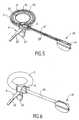
- said circuit of the antenna of reception 30is foldable ( Figures 8 and 9) resiliently so that the surgeon can momentarily reduce the dimensions of the part implantable of the system i.e. the ring, the sheath 33 and the circuit the receiving antenna 30 for passing the monobloc assembly into a small trocar, preferably of smaller diameter by example at 15 mm, this in order to facilitate the installation.
- the circuit of the reception antenna 30 foldingwill be advantageously but not necessarily flexible, either by all, or at least in part, and formed by a flexible electrical circuit 40, appearing for example in the form of a disc coated in a silicone envelope 41, the latter also serving as protection for electronic component 42 connected and functionally connected to the antenna itself of the flexible circuit 40.
- the circuit for the receiving antenna 30will be in the form of a part, for example example in the form of a disc that can be folded in on itself substantially according to disc diameter as shown in Figures 5 and 6.
- the restriction and remote control systemalso includes a transmitting antenna (not shown in the figures) arranged outside the patient to send a command and power to the reception antenna 30, said transmitting antenna being itself functionally connected to a control interface, such as a PC or any other equivalent means available to the attending physician.
- a transmitting antenna(not shown in the figures) arranged outside the patient to send a command and power to the reception antenna 30, said transmitting antenna being itself functionally connected to a control interface, such as a PC or any other equivalent means available to the attending physician.
- the treating physiciancan position it on the patient's skin the transmitting antenna in a face-to-face position with the receiving antenna 30.
- the doctorcan then send a command and power signal towards the receiving antenna 30, to transmit to it both the energy required to actuate the actuator 8 and at the same time control its direction of movement.
- the systemis also particularly safe, since only the attending physician has the control box including the antenna which allows it to exercise full control over the operation of diameter adjustment. The patient cannot therefore have free access to a any means of adjusting the diameter of the ring.
- the inventiontherefore also relates to a new treatment method surgical and therapeutic using the restriction system and remote control of food intake according to the invention.
Landscapes
- Health & Medical Sciences (AREA)
- Child & Adolescent Psychology (AREA)
- Obesity (AREA)
- Nursing (AREA)
- Orthopedic Medicine & Surgery (AREA)
- Engineering & Computer Science (AREA)
- Biomedical Technology (AREA)
- Heart & Thoracic Surgery (AREA)
- Vascular Medicine (AREA)
- Life Sciences & Earth Sciences (AREA)
- Animal Behavior & Ethology (AREA)
- General Health & Medical Sciences (AREA)
- Public Health (AREA)
- Veterinary Medicine (AREA)
- Surgical Instruments (AREA)
- Prostheses (AREA)
Abstract
Description
Translated fromFrenchLa présente invention se rapporte au domaine technique des implantschirurgicaux destinés à être implantés dans le corps d'un patient autourd'organes biologiques constituant une poche ou un conduit, et plusparticulièrement aux anneaux gastriques conçus pour traiter l'obésité parimplantation d'un anneau gastrique souple, destiné à former une bouclefermée autour de l'estomac pour réduire le diamètre de l'ouverture du stoma,l'invention se rapportant plus particulièrement aux anneaux de gastroplastieà commande à distance, n'impliquant aucune opération invasivepostérieurement à sa mise en place.The present invention relates to the technical field of implantsintended to be implanted in the body of a patient aroundbiological organs that make up a pocket or conduit, and moreparticularly gastric bands designed to treat obesity byimplantation of a flexible gastric band, intended to form a loopclosed around the stomach to reduce the diameter of the opening of the stoma,the invention relating more particularly to gastroplasty ringsremotely controlled, involving no invasive operationafter its installation.
La présente invention concerne un anneau chirurgical destiné à être implantédans le corps d'un patient autour d'organes biologiques constituant unepoche ou un conduit pour, d'une part former une boucle fermée entre sesdeux extrémités formant ainsi respectivement une première et une deuxièmeextrémité et, d'autre part, réduire le diamètre de l'ouverture dudit organelorsqu'il est enserré par l'anneau, ledit anneau comprenant un système pourcommander de manière précise et réversible la variation du diamètre del'anneau.The present invention relates to a surgical ring intended to be implantedin the body of a patient around biological organs constituting apocket or conduit for, on the one hand forming a closed loop between itstwo ends thus forming respectively a first and a secondend and, on the other hand, reduce the diameter of the opening of said memberwhen enclosed by the ring, said ring comprising a system forprecisely and reversibly control the variation of the diameter ofthe ring.
L'invention concerne plus particulièrement un anneau de gastroplastie, maiselle peut aussi concerner un anneau conçu pour être utilisé pour traiterl'incontinence urinaire ou fécale (sphincter artificiel) ou encore un anneauconçu pour régler le débit sanguin dans des vaisseaux sanguins parexemple, cette liste n'étant nullement limitative.The invention relates more particularly to a gastroplasty ring, butit can also relate to a ring designed to be used to treaturinary or fecal incontinence (artificial sphincter) or a ringdesigned to regulate blood flow to blood vessels byexample, this list is by no means exhaustive.
La présente invention concerne plus particulièrement un anneau degastroplastie à commande à distance évitant ainsi toute ré-intervention chirurgicale invasive de réglage du diamètre de l'anneau, ledit anneau étantalors intégré dans un système de restriction et de contrôle à distance del'ingestion d'aliments dans l'estomac d'un patient, comportant un anneaugastrique pourvu d'un actionneur relié à une antenne de réception pourrecevoir un signal de commande, ainsi qu'une antenne émettrice disposée àl'extérieur du patient pour envoyer un signal de commande à l'antenne deréception, puis à l'actionneur.The present invention relates more particularly to a ring ofremotely controlled gastroplasty thus avoiding any re-interventioninvasive surgical adjustment of the diameter of the ring, said ring beingthen integrated into a restriction and remote control system ofingestion of food in the stomach of a patient, having a ringgastric system provided with an actuator connected to a receiving antenna forreceive a control signal, as well as a transmitting antenna arranged atoutside the patient to send a command signal to the antennareception, then to the actuator.
Dans son application préférentielle, l'anneau conforme à l'invention estcommandé par radiofréquence, l'actionneur étant d'une part, relié à l'antennede réception par un circuit de réception dans lequel est intégré ladite antenneet d'autre part, comportant un boítier électrique de commande relié àl'antenne émettrice.In its preferred application, the ring according to the invention iscontrolled by radio frequency, the actuator being on the one hand connected to the antennareception by a reception circuit in which said antenna is integratedand secondly, comprising an electrical control box connected tothe transmitting antenna.
Il est déjà connu d'intervenir de manière chirurgicale sur des patient atteintsd'obésité extrêmement sévère (obésité morbide), c'est-à-dire dans le cas depatient dont le poids excède par exemple le poids idéal d'au moins 50 kg enimplantant des anneaux de gastroplastie sur de tels patients. De tellesinterventions permettent d'éviter non seulement une série de problèmes desanté graves provenant d'un tel surpoids, mais encore et surtout d'éviter unemort certaine et proche de ces patients.It is already known to operate surgically on patients withextremely severe obesity (morbid obesity), i.e. in the case ofpatient whose weight exceeds for example the ideal weight by at least 50 kg inimplanting gastroplasty rings on such patients. Suchinterventions not only prevent a range of problems fromserious health from such an overweight, but still and above all to avoidcertain and near death of these patients.
Il est en effet acquis que les patients souffrant d'obésité morbide voient leurespérance de vie réduite de manière importante, et d'au moins une dizaine àune quinzaine d'années tout en créant d'importants problèmes de chargepsychologique. Par ailleurs, toute une série de phénomènes annexes desanté sont impliqués, ayant une incidence sur l'apparition de maladiesannexes telles que des maladies cardio-vasculaires ou encore telles quel'hypertension, le diabète ou encore des arthrites sévères notamment.It is indeed established that patients suffering from morbid obesity see theirsignificantly reduced life expectancy, and at least ten tofifteen years while creating significant load problemspsychological. In addition, a whole series of additional phenomena ofhealth are involved, affecting the onset of diseaseappendices such as cardiovascular diseases or even such ashypertension, diabetes or even severe arthritis in particular.
Il est également acquis que, pour de tels patients, les traitements basés surdes diètes sévères combinées à une série d'exercices physiques, associéségalement à une modification du comportement, notamment alimentaire,sont peu adaptés, même si ces méthodes de traitement sont reconnuescomme étant les plus saines.It is also recognized that, for such patients, treatments based onsevere diets combined with a series of physical exercises, associatedalso to a modification of behavior, in particular food,are poorly adapted, even if these treatment methods are recognizedas the healthiest.
C'est la raison pour laquelle les traitements efficaces et à long terme del'obésité morbide font intervenir un traitement chirurgical.This is the reason why effective and long-term treatments forMorbid obesity involves surgical treatment.
De manière générale, on distingue les techniques de traitement chirurgicalfaisant intervenir un défaut d'absorption des aliments, c'est-à-dire unraccourcissement du passage des aliments et des sucs digestifs et lestechniques faisant intervenir une restriction gastrique réduisant la taille del'estomac.Generally speaking, a distinction is made between surgical treatment techniquesinvolving a lack of absorption of food, i.e. ashortening of the passage of food and digestive juices andtechniques involving gastric restriction reducing the size ofthe stomach.
Les techniques chirurgicales impliquant un défaut d'absorption sont cellesimpliquant par exemple une technique de «by pass » ou de dérivation dupetit intestin, ou encore celles mettant en oeuvre une séparation du passagedes aliments relativement aux sucs digestifs. Ces techniques chirurgicalessont relativement lourdes et peuvent donner lieu à de sévères complications,et c'est la raison pour laquelle elles ne sont plus guère utilisées maintenant.Surgical techniques involving a defect in absorption are those involving, for example, a "bypass " technique or bypass of the small intestine, or those using separation of the passage of food relative to the digestive juices. These surgical techniques are relatively cumbersome and can lead to severe complications, which is why they are hardly used anymore.
On tend en effet maintenant à utiliser des techniques chirurgicales quimettent en oeuvre des interventions chirurgicales plus réduites, telle que larestriction gastrique impliquant la pose d'un anneau gastrique.Now we tend to use surgical techniques whichimplement more reduced surgical procedures, such asgastric restriction involving the placement of a gastric band.
Ces techniques sont maintenant d'utilisation assez courante et pour laplupart mettent en oeuvre, tel que décrit par exemple dans le brevetUS-5 074 868, une bande souple en matériau élastomère destinée à êtreimplantée autour de l'estomac, en formant une boucle fermée définissant undiamètre fixe pré-établi de l'anneau grâce à un système de fermeture. Le corps de la bande souple comporte une cavité ou chambre de compression àvolume variable, qui est reliée à un cathéter de réglage permettant d'injecterou de retirer un fluide dans la chambre de compression, de manière à fairevarier le diamètre interne de la boucle pour modifier ou régler le diamètre dustoma. Ainsi, en combinaison avec le diamètre fixe et pré-établi de l'anneau,on peut régler dans une faible proportion le diamètre de l'anneau, ce quipermet de réguler le diamètre du stoma et donc de régler la quantitéd'aliments ingérés.These techniques are now quite common and for themost implement, as described for example in the patentUS-5,074,868, a flexible strip of elastomeric material intended to beimplanted around the stomach, forming a closed loop defining afixed pre-established diameter of the ring thanks to a closing system. Thebody of the flexible strip has a cavity or compression chambervariable volume, which is connected to an adjustment catheter for injectingor to withdraw a fluid in the compression chamber, so as to makevary the internal diameter of the loop to modify or adjust the diameter of thestoma. So, in combination with the fixed and pre-established diameter of the ring,the diameter of the ring can be adjusted in a small proportion, whichallows to regulate the diameter of the stoma and thus to regulate the quantityingested food.
Ces dispositifs connus donnent généralement satisfaction mais souffrentnéanmoins d'un certain nombre d'inconvénients liés essentiellement auxdifficultés provenant des interventions chirurgicales effectuées après la posede l'anneau gastrique. En effet, il s'avère qu'en dépit de la possibilité depouvoir modifier dans une certaine mesure le diamètre de l'anneau sansintervention chirurgicale majeure, grâce à la présence d'un boítier miniaturiséimplanté sous la peau du patient, la pose de tels anneaux peuts'accompagner de phénomènes d'intolérance, accompagnés par exemple devomissements, liés à diverses causes et notamment à une trop forteréduction du diamètre du stoma, ou encore à une action inefficace del'anneau liée à un diamètre du stoma trop important, ou encore tout simple àun gêne ou une infection ou une inflammation locale ou générale.These known devices generally give satisfaction but suffernevertheless, a certain number of disadvantages linked essentially todifficulties from surgical procedures performed after installationof the gastric band. Indeed, it turns out that despite the possibility ofability to modify ring diameter to some extent withoutmajor surgical intervention, thanks to the presence of a miniaturized caseimplanted under the patient's skin, fitting such rings canbe accompanied by intolerance, accompanied for example byvomiting, linked to various causes and in particular to excessivereduction in the diameter of the stoma, or to an ineffective action ofthe ring linked to a diameter of the stoma too large, or even very simple todiscomfort or local or general infection or inflammation.
C'est la raison pour laquelle il s'avère souvent nécessaire d'intervenir ànouveau de manière chirurgicale, soit pour soulager le patient, soit pourmodifier ou changer l'anneau préalablement implanté. De telles interventionschirurgicales sont particulièrement sévères et nécessitent le plus souvent ladécoupe de l'anneau par un chirurgien, s'accompagnant de son changementet de son remplacement.This is why it is often necessary to intervene atagain surgically, either to relieve the patient or tomodify or change the previously implanted ring. Such interventionsare particularly severe and most often requirecutting of the ring by a surgeon, accompanied by its changeand its replacement.
En définitive, de telles opérations sont difficiles à réaliser, difficilementsupportées par le patient, coûteuses et ce d'autant plus qu'elles impliquent ladestruction d'un anneau et son remplacement.Ultimately, such operations are difficult to carry out, hardlyborne by the patient, expensive and all the more so as they imply thedestruction of a ring and its replacement.
Avec ces techniques classiques, on constate également une perteprogressive et graduelle de pression à l'intérieur de l'anneau due à unphénomène naturel d'osmose à travers la paroi ce qui nécessite desinterventions régulières pour réajuster le diamètre de l'anneau et contribue àaccroítre le besoin de surveillance constante du patient.With these conventional techniques, there is also a lossprogressive and gradual pressure inside the ring due to anatural phenomenon of osmosis through the wall which requiresregular interventions to readjust the diameter of the ring and contributes toincrease the need for constant patient monitoring.
Enfin, il s'avère que le recours à une simple seringue généralement remplied'eau physiologique pour assurer le réajustement diamétral de l'anneau parinjection du liquide à travers un boítier sous-cutané relié à l'anneau est uneopération qui par sa simplicité peut échapper à tout contrôle médical et êtreeffectuée par le patient lui-même. Les conditions optimales de sécurité et decontrôle ne sont donc pas remplies dans le cas de ces techniquesclassiques.Finally, it turns out that the use of a simple syringe usually filledphysiological water to ensure the diametric readjustment of the ring byinjection of the liquid through a subcutaneous housing connected to the ring is aoperation which by its simplicity can escape all medical control and beperformed by the patient himself. Optimal security andcontrol are therefore not met in the case of these techniquesclassics.
Pour tenter de remédier à ces inconvénients, il a déjà été proposé, tel quedécrit par exemple dans la demande de brevet EP-0 876 808 de réaliser unanneau gastrique qui soit réglable d'une manière non invasive et sansinconfort pour le patient en commandant à distance, sans interventionchirurgicale invasive, des moyens électromagnétiques implantés dans lecorps du patient et montés au moins en partie sur l'anneau gastrique. Lesmoyens mis en oeuvre comprennent une boíte de commande implantée dansl'anneau et raccordée à un réservoir de fluide, également implanté dans lecorps du patient et chargé, à l'aide d'une pompe commandée de l'extérieurdu corps du patient par l'intermédiaire de moyens électromagnétiques,d'injecter ou retirer du fluide dans l'anneau gastrique afin de régler sondiamètre. L'ensemble du dispositif est sous la commande d'un moyen de contrôle externe, du genre micro-ordinateur équipé d'un émetteur-récepteurradio par exemple sous contrôle du médecin traitant.In an attempt to remedy these drawbacks, it has already been proposed, such asdescribed for example in patent application EP-0 876 808 to produce agastric band that is adjustable in a non-invasive and withoutdiscomfort for the patient when ordering remotely, without interventioninvasive surgery, electromagnetic means implanted in thepatient's body and mounted at least in part on the gastric band. Themeans used include a control box located inthe ring and connected to a fluid reservoir, also located in thepatient's body loaded, using an externally controlled pumpof the patient's body by electromagnetic means,inject or withdraw fluid into the gastric band to adjust itsdiameter. The entire device is under the control of a means ofexternal control, of the microcomputer type equipped with a transceiverradio, for example under the supervision of the attending physician.
Un tel dispositif marque bien évidemment une évolution intéressante etbénéfique pour les patients, mais souffre néanmoins d'un certain nombred'inconvénients liés en particulier à la nécessité d'implanter dans le corpsmême du patient un réservoir de fluide, dont l'implantation est délicate etdont l'étanchéité est difficile à réaliser, ce qui peut représenter un dangerpour le patient. Par ailleurs, un tel dispositif nécessite une source d'énergieinterne, par exemple une pile, implantée dans le corps même du patient, cequi une nouvelle fois complique l'intervention chirurgicale et surtout confèreune certaine fragilité générale au système, et peut nécessiter uneintervention chirurgicale destinée à changer la pile.Such a device obviously marks an interesting development andbeneficial for patients but nevertheless suffers from a numberdisadvantages linked in particular to the need to implant in the bodyeven from the patient a fluid reservoir, the implantation of which is delicate andwhose sealing is difficult to achieve, which can represent a dangerfor the patient. Furthermore, such a device requires a power sourceinternal, for example a battery, implanted in the patient's own body, thiswhich again complicates the surgical intervention and above all givesa certain general fragility to the system, and may require asurgery to change the battery.
L'invention vise en conséquence à porter remède aux différentsinconvénients énumérés précédemment, et à proposer un nouvel anneauchirurgical présentant un système de commande réversible de la variation deson diamètre, qui soit particulièrement simple, sûr et efficace, notamment enmatière de précision et de rendement, de telle sorte qu'il puisse être intégrédans un système de commande à distance ne nécessitant pas une énergieimportante de commande.The invention therefore aims to remedy the variousdisadvantages listed above, and to propose a new ringwith a reversible control system for the variation ofits diameter, which is particularly simple, safe and effective, especially inmatter of precision and performance, so that it can be integratedin a remote control system that does not require energyimportant order.
Un autre objet de l'invention vise à proposer un nouvel anneau chirurgical,notamment gastrique dont la commande mécanique soit particulièrementprécise.Another object of the invention aims to propose a new surgical ring,especially gastric whose mechanical control is particularlyprecise.
Un autre objet de l'invention vise à proposer un nouvel anneau chirurgical,notamment gastrique, susceptible de présenter une forme circulaire enutilisation, tout en procurant une grande sécurité de commande.Another object of the invention aims to propose a new surgical ring,in particular gastric, likely to have a circular shape inuse, while providing great control security.
Un autre objet de l'invention vise à proposer un nouvel anneau chirurgical,notamment gastrique permettant de mettre en oeuvre des moyensmécaniques particulièrement éprouvés et résistants, de manière à obtenir unanneau gastrique d'une grande robustesse et d'une bonne longévité.Another object of the invention aims to propose a new surgical ring,in particular gastric allowing to implement meansparticularly proven and resistant mechanical, so as to obtain agastric band of great robustness and good longevity.
Un autre objet de l'invention vise à proposer un nouvel anneau chirurgical,notamment gastrique qui, tout en permettant une bonne maítrise de lavariation du diamètre de l'anneau, est susceptible de minimiser lesphénomènes d'intolérance par le patient.Another object of the invention aims to propose a new surgical ring,especially gastric which, while allowing good control of thevariation in the diameter of the ring, is likely to minimizephenomena of intolerance by the patient.
Un autre objet de l'invention vise à proposer un nouvel anneau chirurgical,notamment gastrique dont le système de commande est particulièrementéconome en matière d'énergie utilisée.Another object of the invention aims to propose a new surgical ring,especially gastric whose control system is particularlyeconomical in terms of energy used.
Un autre objet de l'invention vise à proposer un nouvel anneau gastriqued'encombrement particulièrement réduit, permettant une implantation faciledans l'estomac du patient.Another object of the invention is to propose a new gastric bandparticularly compact, allowing easy installationin the patient's stomach.
Un autre objet de l'invention vise à proposer un nouvel anneau chirurgical,notamment gastrique qui permet une bonne répartition de l'ensemble desefforts de fermeture de l'anneau sur l'estomac.Another object of the invention aims to propose a new surgical ring,particularly gastric which allows a good distribution of allefforts to close the ring on the stomach.
Un autre objet de l'invention vise à proposer un nouveau système derestriction et de contrôle à distance de l'ingestion d'aliments dans l'estomacd'un patient qui soit particulièrement efficace, d'une grande robustesse etd'une bonne longévité, tout en requérant une énergie d'alimentationrelativement faible.Another object of the invention aims to propose a new system ofrestriction and remote control of food intake in the stomacha patient who is particularly efficient, very robust andgood longevity, while requiring power supplyrelatively weak.
Les objets assignés à l'invention sont atteints à l'aide d'un anneau chirurgicaldestiné être implanté dans le corps d'un patient autour d'organes biologiquesconstituant une poche ou un conduit pour, d'une part former une boucle fermée entre ses deux extrémités formant ainsi une première et unedeuxième extrémités et, d'autre part réduire le diamètre de l'ouverture del'organe biologique lorsqu'il est enserré par l'anneau, ledit anneaucomprenant un système pour commander de manière réversible la variationde son diamètre, caractérisé en ce que ledit système comporte un élémentsouple filiforme inséré longitudinalement et à coulissement dans le matériauformant le corps de l'anneau sensiblement entre les première et deuxièmeextrémités, pour définir une portion fixe solidarisée avec la premièreextrémité et une portion libre associée fonctionnellement à un actionneurmonté sur l'anneau vers la deuxième extrémité, de telle manière quel'actionneur puisse assurer la translation réversible de l'élément souplefiliforme pour obtenir une variation associée du diamètre de l'anneau.The objects assigned to the invention are achieved using a surgical ringintended to be implanted in the body of a patient around biological organsconstituting a pocket or a conduit for, on the one hand forming a loopclosed between its two ends thus forming a first and asecond ends and on the other hand reduce the diameter of the opening ofthe biological organ when it is enclosed by the ring, said ringcomprising a system for reversibly controlling the variationof its diameter, characterized in that said system comprises an elementflexible filiform inserted longitudinally and sliding in the materialforming the body of the ring substantially between the first and secondends, to define a fixed portion secured to the firstend and a free portion functionally associated with an actuatormounted on the ring towards the second end, so thatthe actuator can ensure the reversible translation of the flexible elementfiliform to obtain an associated variation in the diameter of the ring.
Les objets assignés à l'invention sont également atteints à l'aide d'unsystème de restriction et de contrôle à distance de l'ingestion d'aliments dansl'estomac d'un patient comportant :
- un anneau gastrique tel que défini précédemment et comportant en tantqu'actionneur, un moteur électrique qui est relié à une antenne deréception pour recevoir un signal de commande et de puissance,
- une antenne émettrice disposée à l'extérieur du patient pour envoyerun signal de commande et de puissance à l'antenne de réception, laditeantenne émettrice étant reliée fonctionnellement à une interface decommande.
- a gastric band as defined above and comprising, as an actuator, an electric motor which is connected to a reception antenna to receive a control and power signal,
- a transmitting antenna arranged outside the patient for sending a control and power signal to the receiving antenna, said transmitting antenna being operatively connected to a control interface.
D'autres objets et avantages de l'invention apparaítront mieux à la lecture dela description ci-jointe, ainsi qu'à l'aide des dessins annexés, à titre purementillustratif et informatif, dans lesquels :
- La figure 1 représente, selon une vue en coupe longitudinale, un exempled'une première variante de réalisation d'un anneau gastrique conforme àl'invention.
- La figure 2 représente une vue de la section transversale de l'anneaugastrique représenté à la figure 1, ladite coupe étant effectuée selon la ligneII-II de la figure 1.
- La figure 3 représente, selon une vue en coupe longitudinale, une secondevariante de réalisation d'un anneau gastrique conforme à l'invention.
- La figure 4 représente la section transversale de l'anneau gastrique illustréà la figure 3, ladite coupe étant effectuée selon la ligne IV-IV de la figure 3.
- La figure 5 illustre, selon une vue en perspective et selon une vue en coupelongitudinale partielle, un exemple de réalisation d'un anneau gastriqueconforme à l'invention et correspondant à la seconde variante de réalisationillustrée à la figure 3, ledit anneau étant équipé d'une antenne de réceptionen position dépliée.
- La figure 6 représente, selon une vue en perspective, un anneau gastriqueidentique à celui illustré à la figure 5, l'antenne de réception étant en positiondépliée de fonctionnement.
- La figure 7 illustre, selon une vue en perspective, un anneau gastriqueconforme à l'invention illustrant la sortie des fils de connexion électrique.
- La figure 8 illustre, selon une vue en coupe transversale, la position repliéedu circuit de réception de l'anneau avec l'antenne de réception.
- La figure 9 illustre, selon une vue en coupe transversale, le circuit deréception avec son antenne en position dépliée.
- La figure 10 illustre, selon une vue en perspective partielle, un détail deréalisation de l'élément filiforme souple conforme à l'invention et servant auréglage du diamètre de l'anneau.
- Figure 1 shows, in a longitudinal sectional view, an example of a first embodiment of a gastric band according to the invention.
- FIG. 2 represents a view of the cross section of the gastric band shown in FIG. 1, said section being taken along line II-II of FIG. 1.
- Figure 3 shows, in a longitudinal sectional view, a second alternative embodiment of a gastric ring according to the invention.
- FIG. 4 represents the cross section of the gastric band illustrated in FIG. 3, said cut being carried out along line IV-IV of FIG. 3.
- Figure 5 illustrates, in a perspective view and in a partial longitudinal sectional view, an embodiment of a gastric ring according to the invention and corresponding to the second embodiment illustrated in Figure 3, said ring being equipped with a reception antenna in the unfolded position.
- 6 shows, in a perspective view, a gastric ring identical to that illustrated in Figure 5, the receiving antenna being in the unfolded operating position.
- FIG. 7 illustrates, in a perspective view, a gastric ring according to the invention illustrating the outlet of the electrical connection wires.
- Figure 8 illustrates, in a cross-sectional view, the folded position of the receiving circuit of the ring with the receiving antenna.
- FIG. 9 illustrates, in a cross-section view, the reception circuit with its antenna in the unfolded position.
- Figure 10 illustrates, in a partial perspective view, a detail of the flexible filiform element according to the invention and used for adjusting the diameter of the ring.
Dans la description qui suit il sera fait référence, uniquement à titred'exemple, à un anneau gastrique conçu pour être implanté autour del'estomac pour réduire le diamètre de l'ouverture du stoma, ou autour del'oesophage. En effet, l'invention n'est nullement limitée à cette application etvise au contraire à couvrir d'autres anneaux chirurgicaux, tels ceux utiliséspour traiter l'incontinence urinaire ou fécale ou ceux utilisés autour devaisseaux sanguins pour régler le débit sanguin.In the description which follows, reference will be made onlyexample, to a gastric band designed to be implanted aroundstomach to reduce the diameter of the stoma opening, or aroundthe esophagus. The invention is in no way limited to this application andrather aims to cover other surgical rings, such as those usedto treat urinary or fecal incontinence or those used aroundblood vessels to regulate blood flow.
Dans le cas de traitement d'incontinence urinaire, l'anneau sera implantéautour de la vessie ou des voies urinaires, et dans le cas d'incontinencefécale, il sera implanté autour des voies gastro-intestinales, et notammentautour des structures anales de l'intestin.In the case of urinary incontinence treatment, the ring will be implantedaround the bladder or urinary tract, and in the case of incontinencefaecal, it will be implanted around the gastrointestinal tract, and in particulararound the anal structures of the gut.
Les figures 1 à 10 illustrent un anneau gastrique conforme à l'inventiondestiné à être implanté autour de l'estomac d'un patient en formant uneboucle sensiblement circulaire, afin de réaliser une restriction gastrique enréduisant le diamètre de l'ouverture du stoma. L'anneau gastrique conformeà l'invention se présente sous la forme d'une bande flexible tubulaire, dontl'enveloppe souple et élastique présente une surface lisse pour la rendreatraumatique de manière à être facilement supportée par le patient et lestissus de l'estomac. La bande est réalisée par exemple en matériauélastomère.Figures 1 to 10 illustrate a gastric band according to the inventionintended to be implanted around the stomach of a patient by forming asubstantially circular loop, in order to achieve gastric restriction inreducing the diameter of the stoma opening. The conforming gastric bandto the invention is in the form of a flexible tubular strip, of whichthe flexible and elastic envelope has a smooth surface to make itatraumatic so as to be easily supported by the patient andstomach tissue. The strip is made for example of materialelastomer.
La bande flexible tubulaire comporte deux extrémités, respectivement 1, 2,sur lesquelles sont conformés et implantés des moyens de fermeture 9(figures 5 et 6) destinés à coopérer de manière à assurer le verrouillage et lafermeture de l'anneau autour de l'estomac pour réaliser une boucle ferméeentre les deux extrémités 1 et 2, formant ainsi respectivement une premièreet une deuxième extrémités.The flexible tubular strip has two ends, respectively 1, 2,on which are closed and implanted closure means 9(Figures 5 and 6) intended to cooperate so as to ensure locking andclosure of the ring around the stomach to achieve a closed loopbetween the two ends 1 and 2, thus respectively forming a firstand a second end.
L'anneau gastrique conforme à l'invention se présente sous la forme d'untore de révolution, de section par exemple sensiblement cylindrique, délimitéextérieurement par une enveloppe 3 monocouche ou multicouche qui peutêtre avantageusement formée d'un revêtement de protection, par exemple àbase de ou en silicone.The gastric band according to the invention is in the form of atoroid of revolution, of section for example substantially cylindrical, delimitedexternally by a monolayer or
Tel qu'illustré en particulier aux figures 1 et 3, l'anneau gastrique conforme àl'invention comporte avantageusement un élément souple filiforme 4présentant une bonne flexibilité et une bonne résistance mécanique, insérélongitudinalement et à coulissement selon l'axe principal de symétrie ducylindre, ou du corps principal de l'anneau, ledit élément 4 occupant la cavitéreliant les première et deuxième extrémités 1,2 et s'étendant sensiblemententre les première et deuxième extrémités 1, 2, c'est-à-dire sensiblement surtoute la longueur développée de l'anneau.As illustrated in particular in FIGS. 1 and 3, the gastric band conforming tothe invention advantageously comprises a flexible
Tel qu'illustré aux figures, l'élément souple filiforme 4 est monté pour définirainsi une portion fixe 5 qui est solidarisée à l'aide de moyens desolidarisation 6, faisant par exemple intervenir un circlips et une rondelle, outout moyen équivalent, avec la première extrémité 1 de l'anneau. L'autreportion terminale de l'élément souple filiforme 4 forme une portion libre 7,c'est-à-dire susceptible de se déplacer par translation relativement à laportion fixe 5, ladite portion libre 7 étant associée fonctionnellement à unactionneur 8 monté sur l'anneau même vers ou au niveau de la deuxièmeextrémité 2. L'actionneur 8 est chargé de transmettre l'énergie nécessaire pour assurer, lorsqu'il est activé, la translation réversible de l'élément souplefiliforme 4 à l'intérieur de l'anneau, i.e. le déplacement réversible de laportion libre 7 relativement à la portion fixe 5, en vue d'obtenir une variationassociée du périmètre de l'anneau, c'est-à-dire une augmentation ou uneréduction de son diamètre.As illustrated in the figures, the flexible
Le montage direct de l'actionneur 8 sur l'une des extrémités 2 de l'anneaupermet ainsi un gain de place important et une bonne efficacité mécanique.Direct mounting of the
Avantageusement, la portion libre 7, s'étendant par exemple sur unelongueur de l'ordre de quelques centimètres ou sur toute la longueur del'élément souple filiforme, est pourvue de moyens de coopération de force 10(figure 10) avec l'actionneur 8, ledit moyen 10 étant destiné à assurer latransmission de l'énergie fournie par l'actionneur 8 à l'ensemble de l'élémentsouple filiforme 4 à partir de son point d'appui matérialisé par la portionfixe 5.Advantageously, the
Avantageusement, et tel qu'illustré à la figure 10, les moyens de coopérationde force 10 sont formés par un pas de vis.Advantageously, and as illustrated in FIG. 10, the means of
Selon l'invention, l'élément souple filiforme 4 présente une flexibilitésuffisante pour pouvoir s'adapter à la forme sensiblement circulaire del'anneau, tout en étant capable de transmettre la force nécessaire au réglagedu diamètre de l'anneau. Avantageusement, l'élément souple filiforme 4 estformé par une âme souple 11, de préférence métallique, par exemple desection circulaire, sur laquelle est fixé et enroulé coaxialement, par exemplesur toute sa longueur, au moins un ressort à spires non jointives formant lepas de vis.According to the invention, the flexible
De manière particulièrement avantageuse, l'élément souple filiforme 4comporte deux ressorts à spires non jointives pour former le pas de vis, respectivement un premier ressort 12A enroulé hélicoïdalement le long del'âme souple 11 et un second ressort 12B de diamètre extérieur supérieur telqu'illustré à la figure 10, et comportant préférentiellement des spires 14 desection transversale rectangulaire 13, de manière à délimiter une génératriceexterne plane, ledit premier ressort 12A étant interposé entre les spires 14 dusecond ressort 12B pour maintenir un pas de vis carré constant.In a particularly advantageous manner, the flexible
Grâce à cette disposition, il est ainsi possible de conserver constamment unpas sensiblement constant et efficace, même en cas de déformation del'élément souple filiforme 4. Ceci confère au dispositif une grande précisionet une grande efficacité, tout en étant économe en énergie nécessaire à sonfonctionnement en raison du rendement élevé de la transmission par une visà pas carré.Thanks to this arrangement, it is thus possible to constantly keep anot substantially constant and effective, even in the event of deformation ofthe flexible
Grâce à cette disposition, il est possible de garantir une position de réglagestable même lorsque aucune énergie n'est fournie au système.Thanks to this arrangement, it is possible to guarantee an adjustment positionstable even when no energy is supplied to the system.
Le second ressort 12B peut être avantageusement obtenu par découpagelaser d'un tube cylindrique creux, son montage sur et entre les spires 12D dupremier ressort 12A étant effectué après une traction longitudinale. Lesecond ressort 12B est donc animé naturellement d'une force élastiqueintrinsèque de compression tendant à rendre les spires jointives, cette forceintrinsèque étant contrecarrée par les spires 12D du premier ressort 12A,contre lesquelles elles viennent en appui. On bénéficie ainsi d'un pasconstant malgré l'élasticité et la flexibilité naturelles et indispensables del'élément souple allongé 4.The
L'actionneur 8 pourra être de tout moyen classique bien connu de l'hommedu métier susceptible de coopérer avec le pas de vis pour lui transmettre unmouvement. De manière particulièrement avantageuse, l'actionneur 8 pourraêtre pourvu d'un simple écrou permettant d'assurer l'entraínement du pas de vis, l'actionneur 8 pouvant être de manière générale un moyen moteur, dugenre moteur électrique, électromagnétique ou autre, sans pour autant sortirdu cadre de l'invention.The
A titre de variante de réalisation non représentée aux figures, il est bienévidemment possible de remplacer le pas de vis décrit ci-dessus par toutmoyen technique équivalent, et par exemple par une crémaillère engrenantsur un actionneur 8 pourvu d'une roue dentée ou d'un moyen équivalent. Onpeut également envisager de réaliser l'élément souple filiforme 4 sous laforme d'un simple câble, entraíné de manière réversible par un actionneur 8intégrant une poulie.As an alternative embodiment not shown in the figures, it is wellobviously possible to replace the screw thread described above with anyequivalent technical means, for example by a rack and pinionon an
Tel qu'illustré aux figures, l'anneau gastrique conforme à l'invention est, demanière générale, formé par un corps principal à base d'un matériaucompressible 20 formant le matériau de base et qui vient remplir l'intérieur del'enveloppe 3. Dans le matériau compressible 20 est insérélongitudinalement et sensiblement, avec possibilité de coulissement,l'élément souple filiforme 4, tel qu'illustré par exemple aux figures 2 et 4.As illustrated in the figures, the gastric band according to the invention is,generally, formed by a main body based on a materialcompressible 20 forming the base material and which fills the interior withthe
De manière particulièrement avantageuse, le matériau compressible 20 estde l'ePTFE dont les caractéristiques de compressibilité et de stabilité à lastriction conviennent particulièrement bien à ce genre d'application.Particularly advantageously, the
Selon une première variante de réalisation illustrée aux figures 1 et 2,l'anneau conforme à l'invention comprend une enveloppe 3 en matériausilicone et d'épaisseur sensiblement constante qui forme le revêtementextérieur étanche de l'anneau, l'intérieur de l'anneau étant forméexclusivement du matériau compressible 20, par exemple de l'ePTFE, àl'intérieur duquel l'élément souple filiforme 4 est inséré avec un léger jeu.According to a first alternative embodiment illustrated in FIGS. 1 and 2,the ring according to the invention comprises an
L'extrémité 1 comporte une poche 21, par exemple remplie de colle, et danslaquelle est montée et fixée, la portion fixe 5, avec les moyens desolidarisation 6.The
Telle qu'illustrée aux figures 1 et 2, l'extrémité 1 est pourvue d'une languette22 s'étendant vers l'extérieur de l'anneau et destinée à coopérer avec unélément complémentaire femelle 23, solidaire de la même extrémité 1 del'anneau, pour constituer les moyens de fermeture 9, conduisant auverrouillage de l'anneau en formant, par exemple, une bride autour del'extrémité 2.As illustrated in Figures 1 and 2, the
Selon cette première variante de réalisation, l'action de l'actionneur 8 surl'élément souple filiforme 4, transmet une force d'actionnement selon l'unedes directions indiquées par la flèche F illustrée à la figure 1, ce qui a pourconséquence de comprimer ou relâcher, d'une manière sensiblementlongitudinale, le matériau compressible 20 se traduisant par une variationassociée du diamètre de l'anneau, tant interne qu'externe, sensiblement à lamanière d'un noeud coulant.According to this first alternative embodiment, the action of the
La seconde variante de réalisation illustrée aux figures 3 et 4 ne diffère decelle illustrée aux figures 1 et 2 que par l'agencement spécifique del'enveloppe externe 3 dont la périphérie dorsale 25 est renforcée en vue debrider l'extension radiale externe ou centrifuge de l'anneau pour, aucontraire, privilégier la variation radiale interne ou centripète du diamètre del'anneau. De cette manière, on privilégie la variation radiale du diamètre del'anneau à sa périphérie interne qui est opposée à sa périphérie dorsale.The second variant illustrated in FIGS. 3 and 4 does not differ fromthat illustrated in FIGS. 1 and 2 only by the specific arrangement ofthe
Telle qu'illustrée, la périphérie dorsale renforcée 25 peut être réalisée sous laforme d'une enveloppe externe 3 dont seule la périphérie dorsale présenteune surépaisseur, c'est-à-dire une épaisseur dorsale externe plus importanteque le reste de l'enveloppe externe (figure 4). Alternativement ou de manière complémentaire, la périphérie dorsale 25 peut être également réalisée enutilisant un matériau polymère de dureté supérieure à la dureté du reste del'enveloppe en matériau polymère 3. Il est également envisageable, telqu'illustré à la figure 4, de prévoir d'intégrer dans la périphérie dorsalerenforcée 25 un insert de renfort 26, de préférence métallique s'étendant surla majorité de la périphérie de l'anneau entre le matériau compressible 20 etla périphérie dorsale 25. Avantageusement, l'insert 26 peut présenter unemémoire de forme sensiblement circulaire pour obtenir une position de reposélastique circulaire de l'anneau.As illustrated, the reinforced
Grâce à cet agencement, l'augmentation ou la réduction du diamètre del'anneau est limitée à un déplacement radiale réversible, situé au niveau dela périphérie interne de l'anneau opposé à la périphérie dorsale, setraduisant par une variation du diamètre interne de l'anneau en directioncentrifuge ou centripète, selon le sens de la sollicitation imprimée à l'élémentsouple filiforme 4, matérialisé par l'une des directions de la flèche F.Thanks to this arrangement, increasing or reducing the diameter ofthe ring is limited to a reversible radial displacement, located atthe inner periphery of the ring opposite the dorsal periphery, isresulting in a variation of the internal diameter of the ring in directioncentrifugal or centripetal, depending on the direction of stress applied to the element
L'anneau gastrique conforme à l'invention est particulièrement conçu pourêtre intégré dans un système de restriction et de contrôle à distance del'ingestion d'aliments dans l'estomac d'un patient, de telle manière que l'onpuisse commander à distance, sans aucune intervention chirurgicaleinvasive, la variation du diamètre de l'anneau. A cette fin, l'actionneur 8 estun moteur électrique qui est avantageusement relié à un circuit de réceptionsous-cutané pourvu d'une antenne de réception 30 (figures 5 à 7) pourrecevoir un signal radiofréquence de commande et de puissance, l'ensembleétant destiné à être implanté dans le corps du patient.The gastric band according to the invention is particularly designed forbe integrated into a restriction and remote control systemingestion of food into the stomach of a patient in such a way thatcan control remotely, without any surgeryinvasive, the variation in the diameter of the ring. To this end, the
Tel qu'illustré notamment aux figures 5 à 7, le moteur électrique estsolidarisé avec l'extrémité 2, de manière à être déporté à l'extérieur del'anneau, le moteur électrique étant pourvu de manière classique d'un ensemble de paliers et engrenages, reliés fonctionnellement par uneconnexion électrique 31 au circuit de l'antenne de réception 30.As illustrated in particular in FIGS. 5 to 7, the electric motor issecured to the
Dans cette application préférentielle, le moteur électrique est dépourvu detoute source d'alimentation interne, puisque son énergie est fournie par lecircuit de réception 30 lequel convertit les ondes radio-fréquences reçues del'unité de commande à travers l'antenne extérieure en signal de commandedu moteur et en énergie pour assurer son alimentation électrique. L'antennede réception 30 est adaptée et choisie pour recevoir à la fois un signal decommande et un signal de puissance.In this preferred application, the electric motor is devoid ofany internal power source, since its energy is supplied by the
Le faible besoin en énergie du moteur électrique permet d'envoyer parradiofréquence les ordres de commande et l'énergie d'actionnement dumoteur évitant ainsi l'obligation d'avoir à implanter dans le corps même dupatient une source additionnelle d'énergie telle qu'une pile ou une batterie.The low energy requirement of the electric motor allows to send byradio frequency the control commands and the actuation energy of themotor thus avoiding the obligation to have to implant in the very body of thepatient an additional source of energy such as a battery or a battery.
Tel qu'illustré à la figure 5, le moteur électrique est relié à l'antenne deréception 30 par une connexion électrique 31 qui est protégée par une gaine33 de protection assurant l'étanchéité et au bout de laquelle est montée leditcircuit de réception comportant l'antenne de réception 30. La portion libre 7de l'élément souple filiforme 4 est également intégrée dans la gaine 33 demanière à obtenir un ensemble parfaitement protégé, étanche et susceptibled'agresser le moins possible les tissus environnants.As illustrated in Figure 5, the electric motor is connected to the
De manière particulièrement avantageuse, ledit circuit de l'antenne deréception 30 est repliable (figures 8 et 9) de manière élastique afin que lechirurgien puisse momentanément réduire les dimensions de la partieimplantable du système c'est-à-dire l'anneau, la gaine 33 et le circuit del'antenne de réception 30 pour faire passer l'ensemble monobloc dans untrocart de dimension faible, de préférence d'un diamètre inférieur parexemple à 15 mm, ceci afin de faciliter l'implantation.In a particularly advantageous manner, said circuit of the antenna of
Tel qu'illustré aux figures 8 et 9, le circuit de l'antenne de réception 30repliable sera avantageusement mais non nécessairement flexible, soit entotalité, soit au moins en partie, et formée par un circuit électrique souple 40,se présentant par exemple sous la forme d'un disque enrobé dans uneenveloppe silicone 41, cette dernière servant également de protection à descomposant électroniques 42 connectés et reliés fonctionnellement àl'antenne proprement dite du circuit souple 40.As illustrated in FIGS. 8 and 9, the circuit of the
Selon une version particulièrement avantageuse de l'invention, le circuit del'antenne de réception 30 se présentera sous la forme d'une pièce, parexemple en forme de disque repliable sur lui-même sensiblement selon lediamètre du disque tel que montré aux figures 5 et 6.According to a particularly advantageous version of the invention, the circuit forthe receiving
Grâce à cette disposition et aux propriétés d'élasticité et de souplesse desmatériaux choisis, il est ainsi possible à partir de la position dépliée du circuitde l'antenne 30, telle qu'illustrée aux figures 6 et 9, de replier le circuit del'antenne 30 le long de son diamètre pour occuper un volume restreint (figure8), permettant son insertion dans un trocart de section circulaire, dont lecontour 45 est représenté en ligne pointillée à la figure 8.Thanks to this arrangement and to the elasticity and flexibility properties of thechosen materials, it is thus possible from the unfolded position of the
Le système de restriction et de contrôle à distance conforme à l'inventioncomporte également une antenne émettrice (non représentée aux figures)disposée à l'extérieur du patient pour envoyer un signal de commande et depuissance à l'antenne de réception 30, ladite antenne émettrice étant elle-mêmereliée fonctionnellement à une interface de commande, tel qu'un PCou tout autre moyen équivalent à la disposition du médecin traitant.The restriction and remote control system according to the inventionalso includes a transmitting antenna (not shown in the figures)arranged outside the patient to send a command andpower to the
En utilisation et une fois l'anneau gastrique conforme à l'invention implantéavec son circuit de réception muni de l'antenne 30 en position dépliée dansle corps du patient, le médecin traitant peut positionner sur la peau du patientl'antenne émettrice en position de face à face avec l'antenne de réception 30. Le médecin peut alors envoyer un signal de commande et de puissanceen direction de l'antenne de réception 30, pour lui transmettre à la foisl'énergie nécessaire pour actionner l'actionneur 8 et en même tempscommander son sens de déplacement.In use and once the gastric band according to the invention implantedwith its reception circuit provided with the
Grâce au système de restriction et de contrôle à distance conforme àl'invention, il est ainsi possible de faire varier le diamètre de l'anneaugastrique sans avoir à pratiquer une intervention chirurgicale invasive et ce àvolonté, puisque plusieurs cycles de commande peuvent être réalisés àintervalles réguliers ou non, sous la seule dépendance du médecin traitant.Thanks to the restriction and remote control system conforming tothe invention, it is thus possible to vary the diameter of the ringwithout having to perform an invasive surgical procedure and this atwill, since several control cycles can be carried out atregular intervals or not, under the sole dependence of the attending physician.
Le système se révèle par ailleurs particulièrement sûr, puisque seul lemédecin traitant possède le boítier de commande comprenant l'antenneémettrice, ce qui lui permet d'exercer un contrôle total sur l'opération deréglage du diamètre. Le patient ne peut donc avoir librement accès à unmoyen quelconque de réglage du diamètre de l'anneau.The system is also particularly safe, since only theattending physician has the control box including the antennawhich allows it to exercise full control over the operation ofdiameter adjustment. The patient cannot therefore have free access to aany means of adjusting the diameter of the ring.
L'invention concerne donc également un nouveau procédé de traitementchirurgical et thérapeutique mettant en oeuvre le système de restriction et decontrôle à distance de l'ingestion d'aliments conforme à l'invention.The invention therefore also relates to a new treatment methodsurgical and therapeutic using the restriction system andremote control of food intake according to the invention.
Claims (20)
Translated fromFrenchPriority Applications (10)
| Application Number | Priority Date | Filing Date | Title |
|---|---|---|---|
| AT02019937TATE369820T1 (en) | 2002-09-04 | 2002-09-04 | SURGICAL RING WITH REMOTE CONTROL DEVICE FOR REVERSIBLE DIAMETER CHANGES |
| EP02019937AEP1396243B1 (en) | 2002-09-04 | 2002-09-04 | Surgical ring with remote control system for reversible variation of diameter |
| DE60221828TDE60221828T2 (en) | 2002-09-04 | 2002-09-04 | Surgical ring with remote control device for reversible diameter changes |
| ES02019937TES2291405T3 (en) | 2002-09-04 | 2002-09-04 | SURGICAL RING PROVIDED WITH A REMOTE CONTROL SYSTEM AND REVERSIBLE IN THE VARIATION OF YOUR DIAMETER. |
| US10/653,808US7238191B2 (en) | 2002-09-04 | 2003-09-03 | Surgical ring featuring a reversible diameter remote control system |
| US10/962,939US7972346B2 (en) | 2002-09-04 | 2004-10-12 | Telemetrically controlled band for regulating functioning of a body organ or duct, and methods of making, implantation and use |
| US10/962,852US7901419B2 (en) | 2002-09-04 | 2004-10-12 | Telemetrically controlled band for regulating functioning of a body organ or duct, and methods of making, implantation and use |
| US11/772,613US8012162B2 (en) | 2002-09-04 | 2007-07-02 | Surgical ring featuring a reversible diameter remote control system |
| US13/039,198US20110152608A1 (en) | 2002-09-04 | 2011-03-02 | Flow control method and device |
| US14/049,052US20140039250A1 (en) | 2002-09-04 | 2013-10-08 | Flow control method and device |
Applications Claiming Priority (1)
| Application Number | Priority Date | Filing Date | Title |
|---|---|---|---|
| EP02019937AEP1396243B1 (en) | 2002-09-04 | 2002-09-04 | Surgical ring with remote control system for reversible variation of diameter |
Publications (2)
| Publication Number | Publication Date |
|---|---|
| EP1396243A1true EP1396243A1 (en) | 2004-03-10 |
| EP1396243B1 EP1396243B1 (en) | 2007-08-15 |
Family
ID=31502727
Family Applications (1)
| Application Number | Title | Priority Date | Filing Date |
|---|---|---|---|
| EP02019937AExpired - LifetimeEP1396243B1 (en) | 2002-09-04 | 2002-09-04 | Surgical ring with remote control system for reversible variation of diameter |
Country Status (5)
| Country | Link |
|---|---|
| US (2) | US7238191B2 (en) |
| EP (1) | EP1396243B1 (en) |
| AT (1) | ATE369820T1 (en) |
| DE (1) | DE60221828T2 (en) |
| ES (1) | ES2291405T3 (en) |
Cited By (26)
| Publication number | Priority date | Publication date | Assignee | Title |
|---|---|---|---|---|
| WO2006040647A1 (en)* | 2004-10-12 | 2006-04-20 | Endoart Sa | Telemetrically controlled band for regulating functioning of a body organ or duct, and methods of making, implantation and use |
| EP1645249A3 (en)* | 2004-09-28 | 2006-07-05 | Ethicon Endo-Surgery, Inc. | An improved fluid adjustable band |
| WO2009112786A3 (en)* | 2008-02-28 | 2009-12-30 | Compagnie Europeenne D'etude Et De Recherche De Dispositifs Pour L'implantation Par Laparoscopie | Implantable device and corresponding method for making same |
| WO2010059379A1 (en)* | 2008-10-30 | 2010-05-27 | Ethicon Endo-Surgery, Inc. | Method and devices for fixing antenna orientation in an intra-gastric satiety creation system |
| US7901419B2 (en) | 2002-09-04 | 2011-03-08 | Allergan, Inc. | Telemetrically controlled band for regulating functioning of a body organ or duct, and methods of making, implantation and use |
| US8251888B2 (en) | 2005-04-13 | 2012-08-28 | Mitchell Steven Roslin | Artificial gastric valve |
| US8753369B2 (en) | 2006-06-09 | 2014-06-17 | Apollo Endosurgery, Inc. | Intragastric balloon retrieval mechanisms |
| US8864840B2 (en) | 2010-10-19 | 2014-10-21 | Apollo Endosurgery, Inc. | Intragastric implants with collapsible frames |
| US8870966B2 (en) | 2010-10-18 | 2014-10-28 | Apollo Endosurgery, Inc. | Intragastric balloon for treating obesity |
| US8882655B2 (en) | 2010-09-14 | 2014-11-11 | Apollo Endosurgery, Inc. | Implantable access port system |
| US8900118B2 (en) | 2008-10-22 | 2014-12-02 | Apollo Endosurgery, Inc. | Dome and screw valves for remotely adjustable gastric banding systems |
| US8920447B2 (en) | 2010-10-19 | 2014-12-30 | Apollo Endosurgery, Inc. | Articulated gastric implant clip |
| US8956380B2 (en) | 2010-10-18 | 2015-02-17 | Apollo Endosurgery, Inc. | Reactive intragastric implant devices |
| US9050165B2 (en) | 2010-09-07 | 2015-06-09 | Apollo Endosurgery, Inc. | Remotely adjustable gastric banding system |
| US9125718B2 (en) | 2010-04-30 | 2015-09-08 | Apollo Endosurgery, Inc. | Electronically enhanced access port for a fluid filled implant |
| US9173757B2 (en) | 2007-04-13 | 2015-11-03 | Apollo Endosurgery, Inc. | Apparatus and method for remote deflation of intragastric balloon |
| US9192501B2 (en) | 2010-04-30 | 2015-11-24 | Apollo Endosurgery, Inc. | Remotely powered remotely adjustable gastric band system |
| US9198790B2 (en) | 2010-10-19 | 2015-12-01 | Apollo Endosurgery, Inc. | Upper stomach gastric implants |
| US9398969B2 (en) | 2010-10-19 | 2016-07-26 | Apollo Endosurgery, Inc. | Upper stomach gastric implants |
| US9463107B2 (en) | 2010-10-18 | 2016-10-11 | Apollo Endosurgery, Inc. | Variable size intragastric implant devices |
| US9498365B2 (en) | 2010-10-19 | 2016-11-22 | Apollo Endosurgery, Inc. | Intragastric implants with multiple fluid chambers |
| US9668901B2 (en) | 2010-10-18 | 2017-06-06 | Apollo Endosurgery Us, Inc. | Intragastric implants with duodenal anchors |
| CN106880401A (en)* | 2017-03-28 | 2017-06-23 | 成都美创医疗科技股份有限公司 | A kind of plasma debridement surgical knife |
| WO2017109016A1 (en)* | 2015-12-21 | 2017-06-29 | Balatech Limited | Flow control valves |
| US10070980B2 (en) | 2010-10-19 | 2018-09-11 | Apollo Endosurgery Us, Inc. | Anchored non-piercing duodenal sleeve and delivery systems |
| CN112754653A (en)* | 2021-01-15 | 2021-05-07 | 江苏省人民医院 | Laparoscope microwave needle |
Families Citing this family (255)
| Publication number | Priority date | Publication date | Assignee | Title |
|---|---|---|---|---|
| ES2435094T3 (en) | 2000-05-19 | 2013-12-18 | C.R. Bard, Inc. | Device and method of tissue capture and suturing |
| US7737109B2 (en) | 2000-08-11 | 2010-06-15 | Temple University Of The Commonwealth System Of Higher Education | Obesity controlling method |
| CA2417129A1 (en) | 2000-08-11 | 2002-02-21 | Temple University Of The Commonwealth System Of Higher Education | Obesity controlling method |
| US7695427B2 (en) | 2002-04-26 | 2010-04-13 | Torax Medical, Inc. | Methods and apparatus for treating body tissue sphincters and the like |
| US7338433B2 (en) | 2002-08-13 | 2008-03-04 | Allergan, Inc. | Remotely adjustable gastric banding method |
| DK1553878T3 (en) | 2002-08-28 | 2010-05-31 | Allergan Inc | Fatigue resistant gastric banding device |
| JP2007527279A (en) | 2004-01-23 | 2007-09-27 | アラーガン、インコーポレイテッド | One-piece adjustable gastric band that can be fixed removably |
| FR2866555B1 (en)* | 2004-02-19 | 2007-02-09 | Cie Euro Etude Rech Paroscopie | ATRAUMATIC SURGICAL RING |
| CA2559056A1 (en) | 2004-03-08 | 2005-09-22 | Endoart S.A. | Closure system for tubular organs |
| EP1732635B1 (en) | 2004-03-18 | 2011-07-27 | Allergan, Inc. | Apparatus for volume adjustment of intragastric balloons |
| FR2869218B1 (en)* | 2004-04-21 | 2006-06-09 | Europlak Sa | GASTRIC CERCLING DEVICE OR MOTORIZED "GASTRIC RING" HAVING AT LEAST ONE RECEIVED ANTENNA FOR DELIVERY, REMOTE CONTROL AND DATA SENDING BY INDUCTION |
| US7955357B2 (en) | 2004-07-02 | 2011-06-07 | Ellipse Technologies, Inc. | Expandable rod system to treat scoliosis and method of using the same |
| AU2005319399B2 (en)* | 2004-12-21 | 2011-05-12 | Davol Inc. | Anastomotic outlet revision |
| US8608797B2 (en) | 2005-03-17 | 2013-12-17 | Valtech Cardio Ltd. | Mitral valve treatment techniques |
| US8333777B2 (en) | 2005-04-22 | 2012-12-18 | Benvenue Medical, Inc. | Catheter-based tissue remodeling devices and methods |
| US8951285B2 (en) | 2005-07-05 | 2015-02-10 | Mitralign, Inc. | Tissue anchor, anchoring system and methods of using the same |
| US9642726B2 (en) | 2005-07-25 | 2017-05-09 | Vascular Dynamics, Inc. | Devices and methods for control of blood pressure |
| US20110077729A1 (en)* | 2009-09-29 | 2011-03-31 | Vascular Dynamics Inc. | Devices and methods for control of blood pressure |
| US20110118773A1 (en)* | 2005-07-25 | 2011-05-19 | Rainbow Medical Ltd. | Elliptical device for treating afterload |
| US9125732B2 (en) | 2005-07-25 | 2015-09-08 | Vascular Dynamics, Inc. | Devices and methods for control of blood pressure |
| WO2010035271A1 (en)* | 2008-09-26 | 2010-04-01 | Vascular Dynamics Inc. | Devices and methods for control of blood pressure |
| US8923972B2 (en) | 2005-07-25 | 2014-12-30 | Vascular Dynamics, Inc. | Elliptical element for blood pressure reduction |
| US9592136B2 (en) | 2005-07-25 | 2017-03-14 | Vascular Dynamics, Inc. | Devices and methods for control of blood pressure |
| US7798954B2 (en) | 2006-01-04 | 2010-09-21 | Allergan, Inc. | Hydraulic gastric band with collapsible reservoir |
| US8043206B2 (en) | 2006-01-04 | 2011-10-25 | Allergan, Inc. | Self-regulating gastric band with pressure data processing |
| US9326877B2 (en) | 2006-09-29 | 2016-05-03 | Apollo Endosurgery, Inc. | Apparatus and method for intragastric balloon with in situ adjustment means |
| US8246533B2 (en) | 2006-10-20 | 2012-08-21 | Ellipse Technologies, Inc. | Implant system with resonant-driven actuator |
| US7862502B2 (en)* | 2006-10-20 | 2011-01-04 | Ellipse Technologies, Inc. | Method and apparatus for adjusting a gastrointestinal restriction device |
| AU2007330338A1 (en) | 2006-12-05 | 2008-06-12 | Valtech Cardio, Ltd. | Segmented ring placement |
| US11259924B2 (en) | 2006-12-05 | 2022-03-01 | Valtech Cardio Ltd. | Implantation of repair devices in the heart |
| US9883943B2 (en) | 2006-12-05 | 2018-02-06 | Valtech Cardio, Ltd. | Implantation of repair devices in the heart |
| US11660190B2 (en) | 2007-03-13 | 2023-05-30 | Edwards Lifesciences Corporation | Tissue anchors, systems and methods, and devices |
| EP1998054B1 (en)* | 2007-05-24 | 2014-08-13 | Parker Origa Holding AG | Pneumatic cylinder with self-adjusting cushioning at the end of stroke and corresponding method |
| US8007429B2 (en)* | 2007-07-05 | 2011-08-30 | Gt Urological, Llc | Vessel occlusive device and method of occluding a vessel |
| US20090112262A1 (en) | 2007-10-30 | 2009-04-30 | Scott Pool | Skeletal manipulation system |
| US8382829B1 (en) | 2008-03-10 | 2013-02-26 | Mitralign, Inc. | Method to reduce mitral regurgitation by cinching the commissure of the mitral valve |
| US11202707B2 (en) | 2008-03-25 | 2021-12-21 | Nuvasive Specialized Orthopedics, Inc. | Adjustable implant system |
| BRPI0910460A2 (en) | 2008-04-17 | 2018-02-14 | Allergan Inc | implantable access door device and fastening system |
| US9023063B2 (en) | 2008-04-17 | 2015-05-05 | Apollo Endosurgery, Inc. | Implantable access port device having a safety cap |
| AU2009257591A1 (en) | 2008-06-11 | 2009-12-17 | Allergan, Inc. | Implantable pump system |
| EP2296744B1 (en) | 2008-06-16 | 2019-07-31 | Valtech Cardio, Ltd. | Annuloplasty devices |
| US8465502B2 (en) | 2008-08-25 | 2013-06-18 | Covidien Lp | Surgical clip applier and method of assembly |
| WO2010042493A1 (en) | 2008-10-06 | 2010-04-15 | Allergan, Inc. | Mechanical gastric band with cushions |
| US11241257B2 (en) | 2008-10-13 | 2022-02-08 | Nuvasive Specialized Orthopedics, Inc. | Spinal distraction system |
| US8382756B2 (en) | 2008-11-10 | 2013-02-26 | Ellipse Technologies, Inc. | External adjustment device for distraction device |
| US8808368B2 (en)* | 2008-12-22 | 2014-08-19 | Valtech Cardio, Ltd. | Implantation of repair chords in the heart |
| US8715342B2 (en) | 2009-05-07 | 2014-05-06 | Valtech Cardio, Ltd. | Annuloplasty ring with intra-ring anchoring |
| US8241351B2 (en) | 2008-12-22 | 2012-08-14 | Valtech Cardio, Ltd. | Adjustable partial annuloplasty ring and mechanism therefor |
| US8147542B2 (en) | 2008-12-22 | 2012-04-03 | Valtech Cardio, Ltd. | Adjustable repair chords and spool mechanism therefor |
| US8940044B2 (en) | 2011-06-23 | 2015-01-27 | Valtech Cardio, Ltd. | Closure element for use with an annuloplasty structure |
| WO2010073246A2 (en) | 2008-12-22 | 2010-07-01 | Valtech Cardio, Ltd. | Adjustable annuloplasty devices and adjustment mechanisms therefor |
| US10517719B2 (en) | 2008-12-22 | 2019-12-31 | Valtech Cardio, Ltd. | Implantation of repair devices in the heart |
| US8926697B2 (en) | 2011-06-23 | 2015-01-06 | Valtech Cardio, Ltd. | Closed band for percutaneous annuloplasty |
| US9011530B2 (en) | 2008-12-22 | 2015-04-21 | Valtech Cardio, Ltd. | Partially-adjustable annuloplasty structure |
| US8911494B2 (en) | 2009-05-04 | 2014-12-16 | Valtech Cardio, Ltd. | Deployment techniques for annuloplasty ring |
| US8353956B2 (en) | 2009-02-17 | 2013-01-15 | Valtech Cardio, Ltd. | Actively-engageable movement-restriction mechanism for use with an annuloplasty structure |
| US8197490B2 (en) | 2009-02-23 | 2012-06-12 | Ellipse Technologies, Inc. | Non-invasive adjustable distraction system |
| US9622792B2 (en) | 2009-04-29 | 2017-04-18 | Nuvasive Specialized Orthopedics, Inc. | Interspinous process device and method |
| EP2424583A2 (en)* | 2009-05-01 | 2012-03-07 | Allergan, Inc. | Laparoscopic gastric band with active agents |
| US20110184229A1 (en)* | 2009-05-01 | 2011-07-28 | Allergan, Inc. | Laparoscopic gastric band with active agents |
| US9968452B2 (en) | 2009-05-04 | 2018-05-15 | Valtech Cardio, Ltd. | Annuloplasty ring delivery cathethers |
| US8523881B2 (en) | 2010-07-26 | 2013-09-03 | Valtech Cardio, Ltd. | Multiple anchor delivery tool |
| US8715158B2 (en) | 2009-08-26 | 2014-05-06 | Apollo Endosurgery, Inc. | Implantable bottom exit port |
| US8708979B2 (en) | 2009-08-26 | 2014-04-29 | Apollo Endosurgery, Inc. | Implantable coupling device |
| US8506532B2 (en) | 2009-08-26 | 2013-08-13 | Allergan, Inc. | System including access port and applicator tool |
| US20110137112A1 (en)* | 2009-08-28 | 2011-06-09 | Allergan, Inc. | Gastric band with electric stimulation |
| WO2011031400A2 (en)* | 2009-08-28 | 2011-03-17 | Allergan, Inc. | Gastric band with electric stimulation |
| JP5751642B2 (en) | 2009-09-04 | 2015-07-22 | エリプス テクノロジーズ, インク.Ellipse Technologies, Inc. | Bone growth apparatus and method |
| US8617049B2 (en)* | 2009-09-18 | 2013-12-31 | Ethicon Endo-Surgery, Inc. | Symmetrical drive system for an implantable restriction device |
| US8523885B2 (en)* | 2009-09-18 | 2013-09-03 | Ethicon Endo-Surgery, Inc. | Implantable restriction system with load monitor |
| US8277502B2 (en)* | 2009-10-29 | 2012-10-02 | Valtech Cardio, Ltd. | Tissue anchor for annuloplasty device |
| US8690939B2 (en) | 2009-10-29 | 2014-04-08 | Valtech Cardio, Ltd. | Method for guide-wire based advancement of a rotation assembly |
| US9011520B2 (en) | 2009-10-29 | 2015-04-21 | Valtech Cardio, Ltd. | Tissue anchor for annuloplasty device |
| US10098737B2 (en) | 2009-10-29 | 2018-10-16 | Valtech Cardio, Ltd. | Tissue anchor for annuloplasty device |
| US9180007B2 (en) | 2009-10-29 | 2015-11-10 | Valtech Cardio, Ltd. | Apparatus and method for guide-wire based advancement of an adjustable implant |
| US8734467B2 (en) | 2009-12-02 | 2014-05-27 | Valtech Cardio, Ltd. | Delivery tool for implantation of spool assembly coupled to a helical anchor |
| US8870950B2 (en) | 2009-12-08 | 2014-10-28 | Mitral Tech Ltd. | Rotation-based anchoring of an implant |
| US8882728B2 (en) | 2010-02-10 | 2014-11-11 | Apollo Endosurgery, Inc. | Implantable injection port |
| US20110201874A1 (en)* | 2010-02-12 | 2011-08-18 | Allergan, Inc. | Remotely adjustable gastric banding system |
| US8678993B2 (en) | 2010-02-12 | 2014-03-25 | Apollo Endosurgery, Inc. | Remotely adjustable gastric banding system |
| US8758221B2 (en) | 2010-02-24 | 2014-06-24 | Apollo Endosurgery, Inc. | Source reservoir with potential energy for remotely adjustable gastric banding system |
| US8840541B2 (en) | 2010-02-25 | 2014-09-23 | Apollo Endosurgery, Inc. | Pressure sensing gastric banding system |
| US8403945B2 (en) | 2010-02-25 | 2013-03-26 | Covidien Lp | Articulating endoscopic surgical clip applier |
| US8764624B2 (en) | 2010-02-25 | 2014-07-01 | Apollo Endosurgery, Inc. | Inductively powered remotely adjustable gastric banding system |
| US8939888B2 (en) | 2010-04-28 | 2015-01-27 | Apollo Endosurgery, Inc. | Method and system for determining the pressure of a fluid in a syringe, an access port, a catheter, and a gastric band |
| US9044298B2 (en) | 2010-04-29 | 2015-06-02 | Apollo Endosurgery, Inc. | Self-adjusting gastric band |
| US9028394B2 (en) | 2010-04-29 | 2015-05-12 | Apollo Endosurgery, Inc. | Self-adjusting mechanical gastric band |
| US20110270024A1 (en) | 2010-04-29 | 2011-11-03 | Allergan, Inc. | Self-adjusting gastric band having various compliant components |
| US8992415B2 (en) | 2010-04-30 | 2015-03-31 | Apollo Endosurgery, Inc. | Implantable device to protect tubing from puncture |
| US9226840B2 (en) | 2010-06-03 | 2016-01-05 | Apollo Endosurgery, Inc. | Magnetically coupled implantable pump system and method |
| US8517915B2 (en) | 2010-06-10 | 2013-08-27 | Allergan, Inc. | Remotely adjustable gastric banding system |
| US9526648B2 (en) | 2010-06-13 | 2016-12-27 | Synerz Medical, Inc. | Intragastric device for treating obesity |
| US10420665B2 (en) | 2010-06-13 | 2019-09-24 | W. L. Gore & Associates, Inc. | Intragastric device for treating obesity |
| US10010439B2 (en) | 2010-06-13 | 2018-07-03 | Synerz Medical, Inc. | Intragastric device for treating obesity |
| US8628554B2 (en) | 2010-06-13 | 2014-01-14 | Virender K. Sharma | Intragastric device for treating obesity |
| US9248043B2 (en) | 2010-06-30 | 2016-02-02 | Ellipse Technologies, Inc. | External adjustment device for distraction device |
| US11653910B2 (en) | 2010-07-21 | 2023-05-23 | Cardiovalve Ltd. | Helical anchor implantation |
| WO2012019052A2 (en) | 2010-08-04 | 2012-02-09 | Micardia Corporation | Percutaneous transcatheter repair of heart valves |
| WO2012021378A2 (en) | 2010-08-09 | 2012-02-16 | Ellipse Technologies, Inc. | Maintenance feature in magnetic implant |
| US9211207B2 (en) | 2010-08-18 | 2015-12-15 | Apollo Endosurgery, Inc. | Power regulated implant |
| US8698373B2 (en) | 2010-08-18 | 2014-04-15 | Apollo Endosurgery, Inc. | Pare piezo power with energy recovery |
| US8961393B2 (en) | 2010-11-15 | 2015-02-24 | Apollo Endosurgery, Inc. | Gastric band devices and drive systems |
| WO2012112396A2 (en) | 2011-02-14 | 2012-08-23 | Ellipse Technologies, Inc. | Device and method for treating fractured bones |
| US8888732B2 (en) | 2011-03-11 | 2014-11-18 | Apollo Endosurgery, Inc. | Intraluminal sleeve with active agents |
| US8725435B2 (en) | 2011-04-13 | 2014-05-13 | Apollo Endosurgery, Inc. | Syringe-based leak detection system |
| US8821373B2 (en) | 2011-05-10 | 2014-09-02 | Apollo Endosurgery, Inc. | Directionless (orientation independent) needle injection port |
| US9402721B2 (en) | 2011-06-01 | 2016-08-02 | Valcare, Inc. | Percutaneous transcatheter repair of heart valves via trans-apical access |
| EP3345573B1 (en) | 2011-06-23 | 2020-01-29 | Valtech Cardio, Ltd. | Closure element for use with annuloplasty structure |
| US10792152B2 (en) | 2011-06-23 | 2020-10-06 | Valtech Cardio, Ltd. | Closed band for percutaneous annuloplasty |
| US9918840B2 (en) | 2011-06-23 | 2018-03-20 | Valtech Cardio, Ltd. | Closed band for percutaneous annuloplasty |
| US8801597B2 (en) | 2011-08-25 | 2014-08-12 | Apollo Endosurgery, Inc. | Implantable access port with mesh attachment rivets |
| US10743794B2 (en) | 2011-10-04 | 2020-08-18 | Nuvasive Specialized Orthopedics, Inc. | Devices and methods for non-invasive implant length sensing |
| US9199069B2 (en) | 2011-10-20 | 2015-12-01 | Apollo Endosurgery, Inc. | Implantable injection port |
| US10016220B2 (en) | 2011-11-01 | 2018-07-10 | Nuvasive Specialized Orthopedics, Inc. | Adjustable magnetic devices and methods of using same |
| US8858623B2 (en) | 2011-11-04 | 2014-10-14 | Valtech Cardio, Ltd. | Implant having multiple rotational assemblies |
| EP3656434B1 (en) | 2011-11-08 | 2021-10-20 | Valtech Cardio, Ltd. | Controlled steering functionality for implant-delivery tool |
| US8858421B2 (en) | 2011-11-15 | 2014-10-14 | Apollo Endosurgery, Inc. | Interior needle stick guard stems for tubes |
| US9089395B2 (en) | 2011-11-16 | 2015-07-28 | Appolo Endosurgery, Inc. | Pre-loaded septum for use with an access port |
| US20130131697A1 (en) | 2011-11-21 | 2013-05-23 | Covidien Lp | Surgical clip applier |
| US8876694B2 (en) | 2011-12-07 | 2014-11-04 | Apollo Endosurgery, Inc. | Tube connector with a guiding tip |
| EP2881083B1 (en) | 2011-12-12 | 2017-03-22 | David Alon | Heart valve repair device |
| US8961394B2 (en) | 2011-12-20 | 2015-02-24 | Apollo Endosurgery, Inc. | Self-sealing fluid joint for use with a gastric band |
| US9364216B2 (en) | 2011-12-29 | 2016-06-14 | Covidien Lp | Surgical clip applier with integrated clip counter |
| WO2013130641A1 (en) | 2012-02-29 | 2013-09-06 | Valcare, Inc. | Percutaneous annuloplasty system with anterior-posterior adjustment |
| US9180008B2 (en) | 2012-02-29 | 2015-11-10 | Valcare, Inc. | Methods, devices, and systems for percutaneously anchoring annuloplasty rings |
| US9532787B2 (en) | 2012-05-31 | 2017-01-03 | Covidien Lp | Endoscopic clip applier |
| US20130338714A1 (en) | 2012-06-15 | 2013-12-19 | Arvin Chang | Magnetic implants with improved anatomical compatibility |
| US9216018B2 (en) | 2012-09-29 | 2015-12-22 | Mitralign, Inc. | Plication lock delivery system and method of use thereof |
| US9044281B2 (en) | 2012-10-18 | 2015-06-02 | Ellipse Technologies, Inc. | Intramedullary implants for replacing lost bone |
| WO2014064694A2 (en) | 2012-10-23 | 2014-05-01 | Valtech Cardio, Ltd. | Controlled steering functionality for implant-delivery tool |
| EP2911593B1 (en) | 2012-10-23 | 2020-03-25 | Valtech Cardio, Ltd. | Percutaneous tissue anchor techniques |
| EP2911616B1 (en) | 2012-10-29 | 2020-10-07 | NuVasive Specialized Orthopedics, Inc. | Adjustable devices for treating arthritis of the knee |
| WO2014087402A1 (en) | 2012-12-06 | 2014-06-12 | Valtech Cardio, Ltd. | Techniques for guide-wire based advancement of a tool |
| US20150351906A1 (en) | 2013-01-24 | 2015-12-10 | Mitraltech Ltd. | Ventricularly-anchored prosthetic valves |
| EP2961351B1 (en) | 2013-02-26 | 2018-11-28 | Mitralign, Inc. | Devices for percutaneous tricuspid valve repair |
| US9179938B2 (en) | 2013-03-08 | 2015-11-10 | Ellipse Technologies, Inc. | Distraction devices and method of assembling the same |
| US10449333B2 (en) | 2013-03-14 | 2019-10-22 | Valtech Cardio, Ltd. | Guidewire feeder |
| US10166100B2 (en) | 2013-03-15 | 2019-01-01 | Valcare, Inc. | Systems and methods for delivery of annuloplasty rings |
| CN105283214B (en) | 2013-03-15 | 2018-10-16 | 北京泰德制药股份有限公司 | Translate conduit, system and its application method |
| US10813751B2 (en) | 2013-05-22 | 2020-10-27 | Valcare, Inc. | Transcatheter prosthetic valve for mitral or tricuspid valve replacement |
| US20160120642A1 (en) | 2013-05-24 | 2016-05-05 | Valcare, Inc. | Heart and peripheral vascular valve replacement in conjunction with a support ring |
| US11058417B2 (en) | 2013-06-28 | 2021-07-13 | Valcare, Inc. | Device, system, and method to secure an article to a tissue |
| US10226242B2 (en) | 2013-07-31 | 2019-03-12 | Nuvasive Specialized Orthopedics, Inc. | Noninvasively adjustable suture anchors |
| US9801734B1 (en) | 2013-08-09 | 2017-10-31 | Nuvasive, Inc. | Lordotic expandable interbody implant |
| US10070857B2 (en) | 2013-08-31 | 2018-09-11 | Mitralign, Inc. | Devices and methods for locating and implanting tissue anchors at mitral valve commissure |
| US10751094B2 (en) | 2013-10-10 | 2020-08-25 | Nuvasive Specialized Orthopedics, Inc. | Adjustable spinal implant |
| WO2015059699A2 (en) | 2013-10-23 | 2015-04-30 | Valtech Cardio, Ltd. | Anchor magazine |
| US9610162B2 (en) | 2013-12-26 | 2017-04-04 | Valtech Cardio, Ltd. | Implantation of flexible implant |
| CN106456215B (en) | 2014-04-28 | 2020-04-10 | 诺威适骨科专科公司 | External adjustment device for adjusting a medical implant |
| EP3174502B1 (en) | 2014-07-30 | 2022-04-06 | Cardiovalve Ltd | Apparatus for implantation of an articulatable prosthetic valve |
| EP3922213A1 (en) | 2014-10-14 | 2021-12-15 | Valtech Cardio, Ltd. | Leaflet-restraining techniques |
| KR102588501B1 (en) | 2014-10-23 | 2023-10-11 | 누베이시브 스페셜라이즈드 오소페딕스, 인크. | Remotely adjustable interactive bone reshaping implant |
| ES2908064T3 (en) | 2014-12-26 | 2022-04-27 | Nuvasive Specialized Orthopedics Inc | distraction systems |
| CN107205747B (en) | 2015-01-15 | 2020-09-08 | 柯惠有限合伙公司 | Reusable endoscopic surgical clip applier |
| CN110141399B (en) | 2015-02-05 | 2021-07-27 | 卡迪尔维尔福股份有限公司 | Prosthetic valve with axial sliding frame |
| US10238427B2 (en) | 2015-02-19 | 2019-03-26 | Nuvasive Specialized Orthopedics, Inc. | Systems and methods for vertebral adjustment |
| US20160256269A1 (en) | 2015-03-05 | 2016-09-08 | Mitralign, Inc. | Devices for treating paravalvular leakage and methods use thereof |
| US10159491B2 (en) | 2015-03-10 | 2018-12-25 | Covidien Lp | Endoscopic reposable surgical clip applier |
| CN107847320B (en) | 2015-04-30 | 2020-03-17 | 瓦尔泰克卡迪欧有限公司 | Valvuloplasty techniques |
| BR112018007347A2 (en) | 2015-10-16 | 2018-10-23 | Nuvasive Specialized Orthopedics, Inc. | adjustable devices for the treatment of knee arthritis |
| CN108348259B (en) | 2015-11-03 | 2020-12-11 | 柯惠有限合伙公司 | Endoscopic Surgical Fixture Applicator |
| US10702280B2 (en) | 2015-11-10 | 2020-07-07 | Covidien Lp | Endoscopic reposable surgical clip applier |
| US10905425B2 (en) | 2015-11-10 | 2021-02-02 | Covidien Lp | Endoscopic reposable surgical clip applier |
| CN108601611B (en) | 2015-12-10 | 2021-11-02 | 诺威适骨科专科公司 | External adjustment device for stretcher |
| US10751182B2 (en) | 2015-12-30 | 2020-08-25 | Edwards Lifesciences Corporation | System and method for reshaping right heart |
| US10828160B2 (en) | 2015-12-30 | 2020-11-10 | Edwards Lifesciences Corporation | System and method for reducing tricuspid regurgitation |
| CN108472044B (en) | 2016-01-11 | 2021-04-16 | 柯惠有限合伙公司 | endoscope-reserved surgical clip applier |
| AU2016388454A1 (en) | 2016-01-18 | 2018-07-19 | Covidien Lp | Endoscopic surgical clip applier |
| BR112018015504A2 (en) | 2016-01-28 | 2018-12-18 | Nuvasive Specialized Orthopedics, Inc. | bone transport systems |
| WO2017139548A1 (en) | 2016-02-10 | 2017-08-17 | Nuvasive Specialized Orthopedics, Inc. | Systems and methods for controlling multiple surgical variables |
| US10531866B2 (en) | 2016-02-16 | 2020-01-14 | Cardiovalve Ltd. | Techniques for providing a replacement valve and transseptal communication |
| US10245133B2 (en)* | 2016-03-01 | 2019-04-02 | University Of Dammam | Medical device for constricting a body passage and a method thereof |
| US10779980B2 (en) | 2016-04-27 | 2020-09-22 | Synerz Medical, Inc. | Intragastric device for treating obesity |
| US10702274B2 (en) | 2016-05-26 | 2020-07-07 | Edwards Lifesciences Corporation | Method and system for closing left atrial appendage |
| GB201611910D0 (en) | 2016-07-08 | 2016-08-24 | Valtech Cardio Ltd | Adjustable annuloplasty device with alternating peaks and troughs |
| US20190231525A1 (en) | 2016-08-01 | 2019-08-01 | Mitraltech Ltd. | Minimally-invasive delivery systems |
| CA3031187A1 (en) | 2016-08-10 | 2018-02-15 | Cardiovalve Ltd. | Prosthetic valve with concentric frames |
| WO2018027788A1 (en) | 2016-08-11 | 2018-02-15 | Covidien Lp | Endoscopic surgical clip applier and clip applying systems |
| CN107753153B (en) | 2016-08-15 | 2022-05-31 | 沃卡尔有限公司 | Device and method for treating heart valve insufficiency |
| CN109640844B (en) | 2016-08-25 | 2021-08-06 | 柯惠Lp公司 | Endoscopic Surgical Clip Appliers and Applicator Systems |
| US10639044B2 (en) | 2016-10-31 | 2020-05-05 | Covidien Lp | Ligation clip module and clip applier |
| US10660651B2 (en) | 2016-10-31 | 2020-05-26 | Covidien Lp | Endoscopic reposable surgical clip applier |
| US10426489B2 (en) | 2016-11-01 | 2019-10-01 | Covidien Lp | Endoscopic reposable surgical clip applier |
| US10492795B2 (en) | 2016-11-01 | 2019-12-03 | Covidien Lp | Endoscopic surgical clip applier |
| US10610236B2 (en) | 2016-11-01 | 2020-04-07 | Covidien Lp | Endoscopic reposable surgical clip applier |
| US10709455B2 (en) | 2017-02-02 | 2020-07-14 | Covidien Lp | Endoscopic surgical clip applier |
| US10758244B2 (en) | 2017-02-06 | 2020-09-01 | Covidien Lp | Endoscopic surgical clip applier |
| US11116514B2 (en) | 2017-02-06 | 2021-09-14 | Covidien Lp | Surgical clip applier with user feedback feature |
| US10660725B2 (en) | 2017-02-14 | 2020-05-26 | Covidien Lp | Endoscopic surgical clip applier including counter assembly |
| US10603038B2 (en) | 2017-02-22 | 2020-03-31 | Covidien Lp | Surgical clip applier including inserts for jaw assembly |
| US10548602B2 (en) | 2017-02-23 | 2020-02-04 | Covidien Lp | Endoscopic surgical clip applier |
| US11583291B2 (en) | 2017-02-23 | 2023-02-21 | Covidien Lp | Endoscopic surgical clip applier |
| CN108618871A (en) | 2017-03-17 | 2018-10-09 | 沃卡尔有限公司 | Bicuspid valve with multi-direction anchor portion or tricuspid valve repair system |
| US11045627B2 (en) | 2017-04-18 | 2021-06-29 | Edwards Lifesciences Corporation | Catheter system with linear actuation control mechanism |
| US10675043B2 (en) | 2017-05-04 | 2020-06-09 | Covidien Lp | Reposable multi-fire surgical clip applier |
| US10722235B2 (en) | 2017-05-11 | 2020-07-28 | Covidien Lp | Spring-release surgical clip |
| US10639032B2 (en) | 2017-06-30 | 2020-05-05 | Covidien Lp | Endoscopic surgical clip applier including counter assembly |
| US10660723B2 (en) | 2017-06-30 | 2020-05-26 | Covidien Lp | Endoscopic reposable surgical clip applier |
| US12064347B2 (en) | 2017-08-03 | 2024-08-20 | Cardiovalve Ltd. | Prosthetic heart valve |
| US11793633B2 (en) | 2017-08-03 | 2023-10-24 | Cardiovalve Ltd. | Prosthetic heart valve |
| US10675112B2 (en) | 2017-08-07 | 2020-06-09 | Covidien Lp | Endoscopic surgical clip applier including counter assembly |
| US10932790B2 (en) | 2017-08-08 | 2021-03-02 | Covidien Lp | Geared actuation mechanism and surgical clip applier including the same |
| US10786262B2 (en) | 2017-08-09 | 2020-09-29 | Covidien Lp | Endoscopic reposable surgical clip applier |
| CN107260246A (en)* | 2017-08-15 | 2017-10-20 | 韩宗霖 | A kind of department of cardiovascular surgery arteriovenous fistula hemostasis device |
| US10786263B2 (en) | 2017-08-15 | 2020-09-29 | Covidien Lp | Endoscopic reposable surgical clip applier |
| US10835341B2 (en) | 2017-09-12 | 2020-11-17 | Covidien Lp | Endoscopic surgical clip applier and handle assemblies for use therewith |
| US10835260B2 (en) | 2017-09-13 | 2020-11-17 | Covidien Lp | Endoscopic surgical clip applier and handle assemblies for use therewith |
| US10758245B2 (en) | 2017-09-13 | 2020-09-01 | Covidien Lp | Clip counting mechanism for surgical clip applier |
| US10653429B2 (en) | 2017-09-13 | 2020-05-19 | Covidien Lp | Endoscopic surgical clip applier |
| US10835221B2 (en) | 2017-11-02 | 2020-11-17 | Valtech Cardio, Ltd. | Implant-cinching devices and systems |
| US10932791B2 (en) | 2017-11-03 | 2021-03-02 | Covidien Lp | Reposable multi-fire surgical clip applier |
| US11376015B2 (en) | 2017-11-03 | 2022-07-05 | Covidien Lp | Endoscopic surgical clip applier and handle assemblies for use therewith |
| US10828036B2 (en) | 2017-11-03 | 2020-11-10 | Covidien Lp | Endoscopic surgical clip applier and handle assemblies for use therewith |
| US11116513B2 (en) | 2017-11-03 | 2021-09-14 | Covidien Lp | Modular surgical clip cartridge |
| US10945734B2 (en) | 2017-11-03 | 2021-03-16 | Covidien Lp | Rotation knob assemblies and surgical instruments including the same |
| US11135062B2 (en) | 2017-11-20 | 2021-10-05 | Valtech Cardio Ltd. | Cinching of dilated heart muscle |
| US10722236B2 (en) | 2017-12-12 | 2020-07-28 | Covidien Lp | Endoscopic reposable surgical clip applier |
| US10849630B2 (en) | 2017-12-13 | 2020-12-01 | Covidien Lp | Reposable multi-fire surgical clip applier |
| US10959737B2 (en) | 2017-12-13 | 2021-03-30 | Covidien Lp | Reposable multi-fire surgical clip applier |
| US10743887B2 (en) | 2017-12-13 | 2020-08-18 | Covidien Lp | Reposable multi-fire surgical clip applier |
| US11051827B2 (en) | 2018-01-16 | 2021-07-06 | Covidien Lp | Endoscopic surgical instrument and handle assemblies for use therewith |
| CN116531147A (en) | 2018-01-24 | 2023-08-04 | 爱德华兹生命科学创新(以色列)有限公司 | Contraction of annuloplasty structures |
| EP4248904A3 (en) | 2018-01-26 | 2023-11-29 | Edwards Lifesciences Innovation (Israel) Ltd. | Techniques for facilitating heart valve tethering and chord replacement |
| US10993721B2 (en) | 2018-04-25 | 2021-05-04 | Covidien Lp | Surgical clip applier |
| EP3820406B1 (en) | 2018-07-12 | 2023-12-20 | Edwards Lifesciences Innovation (Israel) Ltd. | Annuloplasty systems and locking tools therefor |
| US10786273B2 (en) | 2018-07-13 | 2020-09-29 | Covidien Lp | Rotation knob assemblies for handle assemblies |
| US11051828B2 (en) | 2018-08-13 | 2021-07-06 | Covidien Lp | Rotation knob assemblies and surgical instruments including same |
| US11219463B2 (en) | 2018-08-13 | 2022-01-11 | Covidien Lp | Bilateral spring for surgical instruments and surgical instruments including the same |
| US11246601B2 (en) | 2018-08-13 | 2022-02-15 | Covidien Lp | Elongated assemblies for surgical clip appliers and surgical clip appliers incorporating the same |
| US11278267B2 (en) | 2018-08-13 | 2022-03-22 | Covidien Lp | Latch assemblies and surgical instruments including the same |
| US11344316B2 (en) | 2018-08-13 | 2022-05-31 | Covidien Lp | Elongated assemblies for surgical clip appliers and surgical clip appliers incorporating the same |
| US11147566B2 (en) | 2018-10-01 | 2021-10-19 | Covidien Lp | Endoscopic surgical clip applier |
| US11534300B2 (en) | 2018-12-03 | 2022-12-27 | Valcare, Inc. | Stabilizing and adjusting tool for controlling a minimally invasive mitral / tricuspid valve repair system |
| JP2022519380A (en) | 2019-02-07 | 2022-03-23 | ニューベイシブ スペシャライズド オーソペディックス,インコーポレイテッド | Ultrasonic communication in medical devices |
| US11589901B2 (en) | 2019-02-08 | 2023-02-28 | Nuvasive Specialized Orthopedics, Inc. | External adjustment device |
| US11524398B2 (en) | 2019-03-19 | 2022-12-13 | Covidien Lp | Gear drive mechanisms for surgical instruments |
| SG11202112651QA (en) | 2019-05-29 | 2021-12-30 | Valtech Cardio Ltd | Tissue anchor handling systems and methods |
| EP3982881B1 (en) | 2019-06-11 | 2025-04-16 | Valcare Medical, Inc. | Annuloplasty ring with posterior leaflet for minimally invasive treatment |
| US12396853B2 (en) | 2019-06-11 | 2025-08-26 | Valcare Medical, Inc. | Systems and methods for delivery of chordae replacement system |
| US11793628B2 (en) | 2019-07-15 | 2023-10-24 | Valcare, Inc. | Transcatheter bio-prosthesis member and support structure |
| US12364606B2 (en) | 2019-07-23 | 2025-07-22 | Edwards Lifesciences Innovation (Israel) Ltd. | Fluoroscopic visualization of heart valve anatomy |
| JP2022546160A (en) | 2019-08-30 | 2022-11-04 | エドワーズ ライフサイエンシーズ イノベーション (イスラエル) リミテッド | Anchor channel tip |
| EP4034042A1 (en) | 2019-09-25 | 2022-08-03 | Cardiac Implants LLC | Cardiac valve annulus reduction system |
| EP4193934A1 (en) | 2019-10-29 | 2023-06-14 | Edwards Lifesciences Innovation (Israel) Ltd. | Annuloplasty and tissue anchor technologies |
| US11779340B2 (en) | 2020-01-02 | 2023-10-10 | Covidien Lp | Ligation clip loading device |
| US11723669B2 (en) | 2020-01-08 | 2023-08-15 | Covidien Lp | Clip applier with clip cartridge interface |
| US12114866B2 (en) | 2020-03-26 | 2024-10-15 | Covidien Lp | Interoperative clip loading device |
| US12023247B2 (en) | 2020-05-20 | 2024-07-02 | Edwards Lifesciences Corporation | Reducing the diameter of a cardiac valve annulus with independent control over each of the anchors that are launched into the annulus |
| CA3182316A1 (en) | 2020-06-19 | 2021-12-23 | Edwards Lifesciences Innovation (Israel) Ltd. | Self-stopping tissue anchors |
| US12213708B2 (en) | 2020-09-08 | 2025-02-04 | Nuvasive Specialized Orthopedics, Inc. | Remote control module for adjustable implants |
| US12357459B2 (en) | 2020-12-03 | 2025-07-15 | Cardiovalve Ltd. | Transluminal delivery system |
| US20220265326A1 (en) | 2021-02-23 | 2022-08-25 | Nuvasive Specialized Orthopedics, Inc. | Adjustable implant, system and methods |
| US11737787B1 (en) | 2021-05-27 | 2023-08-29 | Nuvasive, Inc. | Bone elongating devices and methods of use |
| EP4380480A1 (en) | 2021-08-03 | 2024-06-12 | NuVasive Specialized Orthopedics, Inc. | Adjustable implant |
| US12419648B2 (en) | 2022-09-26 | 2025-09-23 | Covidien Lp | Two-part fasteners for surgical clip appliers and surgical clip appliers for deploying the same |
Citations (4)
| Publication number | Priority date | Publication date | Assignee | Title |
|---|---|---|---|---|
| US4118805A (en)* | 1977-02-28 | 1978-10-10 | Codman & Shurtleff, Inc. | Artificial sphincter |
| WO2000015158A1 (en)* | 1998-09-14 | 2000-03-23 | Sofradim Production | Gastric constriction device |
| FR2797181A1 (en)* | 1999-08-05 | 2001-02-09 | Richard Cancel | GASTRIC BAND REMOTE CONTROL DEVICE FOR RESTRICTED OPENING OF STOMA IN STOMACH |
| WO2001049245A2 (en)* | 2000-02-10 | 2001-07-12 | Obtech Medical Ag | Mechanical heartburn and reflux disease treatment apparatus |
Family Cites Families (23)
| Publication number | Priority date | Publication date | Assignee | Title |
|---|---|---|---|---|
| US2163048A (en) | 1937-02-13 | 1939-06-20 | Mckee Brothers Corp | Band clamp |
| FR1396243A (en) | 1964-05-27 | 1965-04-16 | Mo I Stali I Splavov | Device for stirring molten metal without contact |
| US3840018A (en)* | 1973-01-31 | 1974-10-08 | M Heifetz | Clamp for occluding tubular conduits in the human body |
| IL67773A (en) | 1983-01-28 | 1985-02-28 | Antebi E | Tie for tying live tissue and an instrument for performing said tying operation |
| US4881939A (en)* | 1985-02-19 | 1989-11-21 | The Johns Hopkins University | Implantable helical cuff |
| US5074868A (en)* | 1990-08-03 | 1991-12-24 | Inamed Development Company | Reversible stoma-adjustable gastric band |
| US5226429A (en)* | 1991-06-20 | 1993-07-13 | Inamed Development Co. | Laparoscopic gastric band and method |
| US5449368A (en)* | 1993-02-18 | 1995-09-12 | Kuzmak; Lubomyr I. | Laparoscopic adjustable gastric banding device and method for implantation and removal thereof |
| US5601604A (en)* | 1993-05-27 | 1997-02-11 | Inamed Development Co. | Universal gastric band |
| US5658298A (en) | 1993-11-09 | 1997-08-19 | Inamed Development Company | Laparoscopic tool |
| US6102922A (en)* | 1995-09-22 | 2000-08-15 | Kirk Promotions Limited | Surgical method and device for reducing the food intake of patient |
| US5997517A (en) | 1997-01-27 | 1999-12-07 | Sts Biopolymers, Inc. | Bonding layers for medical device surface coatings |
| DE69723955D1 (en) | 1997-04-04 | 2003-09-11 | Christian Peclat | Peristaltic pump |
| US5938669A (en)* | 1997-05-07 | 1999-08-17 | Klasamed S.A. | Adjustable gastric banding device for contracting a patient's stomach |
| US6074341A (en)* | 1998-06-09 | 2000-06-13 | Timm Medical Technologies, Inc. | Vessel occlusive apparatus and method |
| US6454699B1 (en) | 2000-02-11 | 2002-09-24 | Obtech Medical Ag | Food intake restriction with controlled wireless energy supply |
| FR2823663B1 (en) | 2001-04-18 | 2004-01-02 | Cousin Biotech | DEVICE FOR TREATING MORBID OBESITY |
| US6511490B2 (en)* | 2001-06-22 | 2003-01-28 | Antoine Jean Henri Robert | Gastric banding device and method |
| US6659937B2 (en)* | 2001-10-11 | 2003-12-09 | M. Sheldon Polsky | Continent bladder access device |
| FR2840804B1 (en) | 2002-06-13 | 2004-09-17 | Richard Cancel | SYSTEM FOR THE TREATMENT OF OBESITY AND IMPLANT FOR SUCH A SYSTEM |
| DK1553878T3 (en) | 2002-08-28 | 2010-05-31 | Allergan Inc | Fatigue resistant gastric banding device |
| ES2295272T3 (en) | 2002-09-04 | 2008-04-16 | Endoart S.A. | CLOSURE SYSTEM FOR SURGICAL RING. |
| FR2855744B1 (en)* | 2003-06-04 | 2006-04-14 | Cie Euro Etude Rech Paroscopie | SURGICAL RING WITH IMPROVED CLOSURE SYSTEM |
- 2002
- 2002-09-04ESES02019937Tpatent/ES2291405T3/ennot_activeExpired - Lifetime
- 2002-09-04EPEP02019937Apatent/EP1396243B1/ennot_activeExpired - Lifetime
- 2002-09-04ATAT02019937Tpatent/ATE369820T1/enactive
- 2002-09-04DEDE60221828Tpatent/DE60221828T2/ennot_activeExpired - Lifetime
- 2003
- 2003-09-03USUS10/653,808patent/US7238191B2/ennot_activeExpired - Lifetime
- 2007
- 2007-07-02USUS11/772,613patent/US8012162B2/ennot_activeExpired - Fee Related
Patent Citations (4)
| Publication number | Priority date | Publication date | Assignee | Title |
|---|---|---|---|---|
| US4118805A (en)* | 1977-02-28 | 1978-10-10 | Codman & Shurtleff, Inc. | Artificial sphincter |
| WO2000015158A1 (en)* | 1998-09-14 | 2000-03-23 | Sofradim Production | Gastric constriction device |
| FR2797181A1 (en)* | 1999-08-05 | 2001-02-09 | Richard Cancel | GASTRIC BAND REMOTE CONTROL DEVICE FOR RESTRICTED OPENING OF STOMA IN STOMACH |
| WO2001049245A2 (en)* | 2000-02-10 | 2001-07-12 | Obtech Medical Ag | Mechanical heartburn and reflux disease treatment apparatus |
Cited By (38)
| Publication number | Priority date | Publication date | Assignee | Title |
|---|---|---|---|---|
| US7901419B2 (en) | 2002-09-04 | 2011-03-08 | Allergan, Inc. | Telemetrically controlled band for regulating functioning of a body organ or duct, and methods of making, implantation and use |
| US7972346B2 (en) | 2002-09-04 | 2011-07-05 | Allergan Medical S.A. | Telemetrically controlled band for regulating functioning of a body organ or duct, and methods of making, implantation and use |
| US7776061B2 (en) | 2004-09-28 | 2010-08-17 | Garner Dean L | Fluid adjustable band |
| EP1645249A3 (en)* | 2004-09-28 | 2006-07-05 | Ethicon Endo-Surgery, Inc. | An improved fluid adjustable band |
| EP2335658A1 (en)* | 2004-10-12 | 2011-06-22 | Allergan Medical Sàrl | Telemetrically controlled band for regulating functioning of a body organ or duct, and methods of making, implantation and use |
| WO2006040647A1 (en)* | 2004-10-12 | 2006-04-20 | Endoart Sa | Telemetrically controlled band for regulating functioning of a body organ or duct, and methods of making, implantation and use |
| AU2005293288B2 (en)* | 2004-10-12 | 2011-06-02 | Allergan Medical Sarl | Telemetrically controlled band for regulating functioning of a body organ or duct, and methods of making, implantation and use |
| US8251888B2 (en) | 2005-04-13 | 2012-08-28 | Mitchell Steven Roslin | Artificial gastric valve |
| US8623042B2 (en) | 2005-04-13 | 2014-01-07 | Mitchell Roslin | Artificial gastric valve |
| US8753369B2 (en) | 2006-06-09 | 2014-06-17 | Apollo Endosurgery, Inc. | Intragastric balloon retrieval mechanisms |
| US9125726B2 (en) | 2006-06-09 | 2015-09-08 | Apollo Endosurgery, Inc. | Intragastric balloon retrieval mechanisms |
| US9173757B2 (en) | 2007-04-13 | 2015-11-03 | Apollo Endosurgery, Inc. | Apparatus and method for remote deflation of intragastric balloon |
| WO2009112786A3 (en)* | 2008-02-28 | 2009-12-30 | Compagnie Europeenne D'etude Et De Recherche De Dispositifs Pour L'implantation Par Laparoscopie | Implantable device and corresponding method for making same |
| US8900118B2 (en) | 2008-10-22 | 2014-12-02 | Apollo Endosurgery, Inc. | Dome and screw valves for remotely adjustable gastric banding systems |
| WO2010059379A1 (en)* | 2008-10-30 | 2010-05-27 | Ethicon Endo-Surgery, Inc. | Method and devices for fixing antenna orientation in an intra-gastric satiety creation system |
| US9192501B2 (en) | 2010-04-30 | 2015-11-24 | Apollo Endosurgery, Inc. | Remotely powered remotely adjustable gastric band system |
| US9125718B2 (en) | 2010-04-30 | 2015-09-08 | Apollo Endosurgery, Inc. | Electronically enhanced access port for a fluid filled implant |
| US9050165B2 (en) | 2010-09-07 | 2015-06-09 | Apollo Endosurgery, Inc. | Remotely adjustable gastric banding system |
| US8882655B2 (en) | 2010-09-14 | 2014-11-11 | Apollo Endosurgery, Inc. | Implantable access port system |
| US9463107B2 (en) | 2010-10-18 | 2016-10-11 | Apollo Endosurgery, Inc. | Variable size intragastric implant devices |
| US9795498B2 (en) | 2010-10-18 | 2017-10-24 | Apollo Endosurgery Us, Inc. | Intragastric balloon for treating obesity |
| US8870966B2 (en) | 2010-10-18 | 2014-10-28 | Apollo Endosurgery, Inc. | Intragastric balloon for treating obesity |
| US9668901B2 (en) | 2010-10-18 | 2017-06-06 | Apollo Endosurgery Us, Inc. | Intragastric implants with duodenal anchors |
| US8956380B2 (en) | 2010-10-18 | 2015-02-17 | Apollo Endosurgery, Inc. | Reactive intragastric implant devices |
| US9198790B2 (en) | 2010-10-19 | 2015-12-01 | Apollo Endosurgery, Inc. | Upper stomach gastric implants |
| US9801747B2 (en) | 2010-10-19 | 2017-10-31 | Apollo Endosurgery Us, Inc. | Non-inflatable gastric implants and systems |
| US9498365B2 (en) | 2010-10-19 | 2016-11-22 | Apollo Endosurgery, Inc. | Intragastric implants with multiple fluid chambers |
| US9539133B2 (en) | 2010-10-19 | 2017-01-10 | Apollo Endosurgery, Inc. | Stomach-spanning gastric implants |
| US8864840B2 (en) | 2010-10-19 | 2014-10-21 | Apollo Endosurgery, Inc. | Intragastric implants with collapsible frames |
| US9681974B2 (en) | 2010-10-19 | 2017-06-20 | Apollo Endosurgery Us, Inc. | Intragastric implants with collapsible frames |
| US10070980B2 (en) | 2010-10-19 | 2018-09-11 | Apollo Endosurgery Us, Inc. | Anchored non-piercing duodenal sleeve and delivery systems |
| US9398969B2 (en) | 2010-10-19 | 2016-07-26 | Apollo Endosurgery, Inc. | Upper stomach gastric implants |
| US8920447B2 (en) | 2010-10-19 | 2014-12-30 | Apollo Endosurgery, Inc. | Articulated gastric implant clip |
| WO2017109016A1 (en)* | 2015-12-21 | 2017-06-29 | Balatech Limited | Flow control valves |
| CN108366852A (en)* | 2015-12-21 | 2018-08-03 | 巴拉技术有限公司 | Flow Control Valve |
| CN106880401A (en)* | 2017-03-28 | 2017-06-23 | 成都美创医疗科技股份有限公司 | A kind of plasma debridement surgical knife |
| CN106880401B (en)* | 2017-03-28 | 2023-05-26 | 成都美创医疗科技股份有限公司 | Plasma debridement scalpel |
| CN112754653A (en)* | 2021-01-15 | 2021-05-07 | 江苏省人民医院 | Laparoscope microwave needle |
Also Published As
| Publication number | Publication date |
|---|---|
| EP1396243B1 (en) | 2007-08-15 |
| DE60221828T2 (en) | 2008-05-08 |
| US7238191B2 (en) | 2007-07-03 |
| DE60221828D1 (en) | 2007-09-27 |
| ATE369820T1 (en) | 2007-09-15 |
| US20050251182A1 (en) | 2005-11-10 |
| US8012162B2 (en) | 2011-09-06 |
| ES2291405T3 (en) | 2008-03-01 |
| US20080027469A1 (en) | 2008-01-31 |
Similar Documents
| Publication | Publication Date | Title |
|---|---|---|
| EP1396243B1 (en) | Surgical ring with remote control system for reversible variation of diameter | |
| EP1396242B1 (en) | Closure system for surgical ring | |
| EP1113767B1 (en) | Gastric constriction device | |
| EP1244399B1 (en) | Gastroplasty ring that can be loosened | |
| EP1635747A1 (en) | Surgical ring with improved closure system | |
| EP1251808B1 (en) | Single control gastric band | |
| EP1303237B1 (en) | Adjustable gastroplasty ring comprising a grip tab | |
| EP2231081B1 (en) | Dual balloon gastric ring | |
| FR2805986A1 (en) | Intra-gastric implant for treating obesity comprises elastic balloon of variable volume linked by connector to fixing on or inside body | |
| FR2802406A1 (en) | Gastroplasty ring has closure opened and closed by pneumatic system | |
| WO2003059215A1 (en) | Gastric ring made of variable hardness elastomeric material | |
| EP1023002A1 (en) | Artificial sphincter with magnetic control | |
| EP1212017A1 (en) | Gastroplasty ring | |
| EP0821598A1 (en) | Device for temporarily closing a canal in a body, in particular for assisting the function of the heart by application of counter-pressure | |
| EP2273955A2 (en) | Gastric ring including a one-piece belt | |
| WO2010121937A1 (en) | Surgical ring with assembled construction | |
| WO2009136124A2 (en) | Surgical ring with gripping tab | |
| FR2879918A1 (en) | Implantable gastric ring for e.g. morbid obesity treatment, has shape of flexible band having male and female closing units, where female closing unit has structural discontinuity with rigidity different from that of rest of closing unit | |
| FR2944433A1 (en) | Surgical ring i.e. gastric ring, for stomach or esophagus of patient, for treating obesity, has gripping tab extending from female unit, where tab and external face of side wall are made of material different hardnesses |
Legal Events
| Date | Code | Title | Description |
|---|---|---|---|
| PUAI | Public reference made under article 153(3) epc to a published international application that has entered the european phase | Free format text:ORIGINAL CODE: 0009012 | |
| AK | Designated contracting states | Kind code of ref document:A1 Designated state(s):AT BE BG CH CY CZ DE DK EE ES FI FR GB GR IE IT LI LU MC NL PT SE SK TR | |
| AX | Request for extension of the european patent | Extension state:AL LT LV MK RO SI | |
| 17P | Request for examination filed | Effective date:20040901 | |
| 17Q | First examination report despatched | Effective date:20041004 | |
| AKX | Designation fees paid | Designated state(s):AT BE BG CH CY CZ DE DK EE ES FI FR GB GR IE IT LI LU MC NL PT SE SK TR | |
| 19A | Proceedings stayed before grant | Effective date:20041011 | |
| 19F | Resumption of proceedings before grant (after stay of proceedings) | Effective date:20060501 | |
| GRAP | Despatch of communication of intention to grant a patent | Free format text:ORIGINAL CODE: EPIDOSNIGR1 | |
| GRAS | Grant fee paid | Free format text:ORIGINAL CODE: EPIDOSNIGR3 | |
| GRAA | (expected) grant | Free format text:ORIGINAL CODE: 0009210 | |
| AK | Designated contracting states | Kind code of ref document:B1 Designated state(s):AT BE BG CH CY CZ DE DK EE ES FI FR GB GR IE IT LI LU MC NL PT SE SK TR | |
| REG | Reference to a national code | Ref country code:GB Ref legal event code:FG4D Free format text:NOT ENGLISH | |
| REG | Reference to a national code | Ref country code:CH Ref legal event code:EP | |
| REG | Reference to a national code | Ref country code:IE Ref legal event code:FG4D Free format text:LANGUAGE OF EP DOCUMENT: FRENCH | |
| REF | Corresponds to: | Ref document number:60221828 Country of ref document:DE Date of ref document:20070927 Kind code of ref document:P | |
| REG | Reference to a national code | Ref country code:SE Ref legal event code:TRGR | |
| GBT | Gb: translation of ep patent filed (gb section 77(6)(a)/1977) | Effective date:20071108 | |
| PG25 | Lapsed in a contracting state [announced via postgrant information from national office to epo] | Ref country code:FI Free format text:LAPSE BECAUSE OF FAILURE TO SUBMIT A TRANSLATION OF THE DESCRIPTION OR TO PAY THE FEE WITHIN THE PRESCRIBED TIME-LIMIT Effective date:20070815 Ref country code:BG Free format text:LAPSE BECAUSE OF FAILURE TO SUBMIT A TRANSLATION OF THE DESCRIPTION OR TO PAY THE FEE WITHIN THE PRESCRIBED TIME-LIMIT Effective date:20071115 | |
| REG | Reference to a national code | Ref country code:ES Ref legal event code:FG2A Ref document number:2291405 Country of ref document:ES Kind code of ref document:T3 | |
| PG25 | Lapsed in a contracting state [announced via postgrant information from national office to epo] | Ref country code:MC Free format text:LAPSE BECAUSE OF NON-PAYMENT OF DUE FEES Effective date:20070930 Ref country code:DK Free format text:LAPSE BECAUSE OF FAILURE TO SUBMIT A TRANSLATION OF THE DESCRIPTION OR TO PAY THE FEE WITHIN THE PRESCRIBED TIME-LIMIT Effective date:20070815 Ref country code:GR Free format text:LAPSE BECAUSE OF FAILURE TO SUBMIT A TRANSLATION OF THE DESCRIPTION OR TO PAY THE FEE WITHIN THE PRESCRIBED TIME-LIMIT Effective date:20071116 | |
| PG25 | Lapsed in a contracting state [announced via postgrant information from national office to epo] | Ref country code:SK Free format text:LAPSE BECAUSE OF FAILURE TO SUBMIT A TRANSLATION OF THE DESCRIPTION OR TO PAY THE FEE WITHIN THE PRESCRIBED TIME-LIMIT Effective date:20070815 Ref country code:PT Free format text:LAPSE BECAUSE OF FAILURE TO SUBMIT A TRANSLATION OF THE DESCRIPTION OR TO PAY THE FEE WITHIN THE PRESCRIBED TIME-LIMIT Effective date:20080115 Ref country code:CZ Free format text:LAPSE BECAUSE OF FAILURE TO SUBMIT A TRANSLATION OF THE DESCRIPTION OR TO PAY THE FEE WITHIN THE PRESCRIBED TIME-LIMIT Effective date:20070815 | |
| PLBE | No opposition filed within time limit | Free format text:ORIGINAL CODE: 0009261 | |
| STAA | Information on the status of an ep patent application or granted ep patent | Free format text:STATUS: NO OPPOSITION FILED WITHIN TIME LIMIT | |
| 26N | No opposition filed | Effective date:20080516 | |
| PG25 | Lapsed in a contracting state [announced via postgrant information from national office to epo] | Ref country code:EE Free format text:LAPSE BECAUSE OF FAILURE TO SUBMIT A TRANSLATION OF THE DESCRIPTION OR TO PAY THE FEE WITHIN THE PRESCRIBED TIME-LIMIT Effective date:20070815 | |
| REG | Reference to a national code | Ref country code:CH Ref legal event code:NV Representative=s name:VOSSIUS & PARTNER | |
| PG25 | Lapsed in a contracting state [announced via postgrant information from national office to epo] | Ref country code:CY Free format text:LAPSE BECAUSE OF FAILURE TO SUBMIT A TRANSLATION OF THE DESCRIPTION OR TO PAY THE FEE WITHIN THE PRESCRIBED TIME-LIMIT Effective date:20070815 | |
| PG25 | Lapsed in a contracting state [announced via postgrant information from national office to epo] | Ref country code:LU Free format text:LAPSE BECAUSE OF NON-PAYMENT OF DUE FEES Effective date:20070904 | |
| PG25 | Lapsed in a contracting state [announced via postgrant information from national office to epo] | Ref country code:TR Free format text:LAPSE BECAUSE OF FAILURE TO SUBMIT A TRANSLATION OF THE DESCRIPTION OR TO PAY THE FEE WITHIN THE PRESCRIBED TIME-LIMIT Effective date:20070815 | |
| REG | Reference to a national code | Ref country code:CH Ref legal event code:PFA Owner name:ALLERGAN MEDICAL SA Free format text:ENDOART S.A.#PARC SCIENTIFIQUE SUR LE SITE DE L'EPFL, PSE#1024 ECUBLENS VD (CH) -TRANSFER TO- ALLERGAN MEDICAL SA#PARC SCIENTIFIQUE EPFL, PSE#1024 ECUBLENS (CH) | |
| NLT1 | Nl: modifications of names registered in virtue of documents presented to the patent office pursuant to art. 16 a, paragraph 1 | Owner name:ALLERGAN MEDICAL S.A. | |
| REG | Reference to a national code | Ref country code:ES Ref legal event code:PC2A | |
| REG | Reference to a national code | Ref country code:FR Ref legal event code:CD | |
| PGFP | Annual fee paid to national office [announced via postgrant information from national office to epo] | Ref country code:CH Payment date:20100930 Year of fee payment:9 | |
| PGFP | Annual fee paid to national office [announced via postgrant information from national office to epo] | Ref country code:AT Payment date:20100819 Year of fee payment:9 | |
| PGFP | Annual fee paid to national office [announced via postgrant information from national office to epo] | Ref country code:NL Payment date:20100924 Year of fee payment:9 | |
| PGFP | Annual fee paid to national office [announced via postgrant information from national office to epo] | Ref country code:BE Payment date:20100927 Year of fee payment:9 | |
| PGFP | Annual fee paid to national office [announced via postgrant information from national office to epo] | Ref country code:SE Payment date:20100929 Year of fee payment:9 | |
| BERE | Be: lapsed | Owner name:ALERGAN MEDICAL S.A. Effective date:20110930 | |
| REG | Reference to a national code | Ref country code:NL Ref legal event code:V1 Effective date:20120401 | |
| REG | Reference to a national code | Ref country code:CH Ref legal event code:PL | |
| PG25 | Lapsed in a contracting state [announced via postgrant information from national office to epo] | Ref country code:BE Free format text:LAPSE BECAUSE OF NON-PAYMENT OF DUE FEES Effective date:20110930 | |
| REG | Reference to a national code | Ref country code:SE Ref legal event code:EUG | |
| PG25 | Lapsed in a contracting state [announced via postgrant information from national office to epo] | Ref country code:CH Free format text:LAPSE BECAUSE OF NON-PAYMENT OF DUE FEES Effective date:20110930 Ref country code:NL Free format text:LAPSE BECAUSE OF NON-PAYMENT OF DUE FEES Effective date:20120401 Ref country code:LI Free format text:LAPSE BECAUSE OF NON-PAYMENT OF DUE FEES Effective date:20110930 | |
| REG | Reference to a national code | Ref country code:AT Ref legal event code:MM01 Ref document number:369820 Country of ref document:AT Kind code of ref document:T Effective date:20110904 | |
| PG25 | Lapsed in a contracting state [announced via postgrant information from national office to epo] | Ref country code:AT Free format text:LAPSE BECAUSE OF NON-PAYMENT OF DUE FEES Effective date:20110904 | |
| PG25 | Lapsed in a contracting state [announced via postgrant information from national office to epo] | Ref country code:SE Free format text:LAPSE BECAUSE OF NON-PAYMENT OF DUE FEES Effective date:20110905 | |
| REG | Reference to a national code | Ref country code:FR Ref legal event code:PLFP Year of fee payment:15 | |
| PGFP | Annual fee paid to national office [announced via postgrant information from national office to epo] | Ref country code:GB Payment date:20160927 Year of fee payment:15 Ref country code:IE Payment date:20160927 Year of fee payment:15 | |
| PGFP | Annual fee paid to national office [announced via postgrant information from national office to epo] | Ref country code:FR Payment date:20160926 Year of fee payment:15 | |
| PGFP | Annual fee paid to national office [announced via postgrant information from national office to epo] | Ref country code:ES Payment date:20160926 Year of fee payment:15 | |
| PGFP | Annual fee paid to national office [announced via postgrant information from national office to epo] | Ref country code:DE Payment date:20160928 Year of fee payment:15 | |
| PGFP | Annual fee paid to national office [announced via postgrant information from national office to epo] | Ref country code:IT Payment date:20160923 Year of fee payment:15 | |
| REG | Reference to a national code | Ref country code:DE Ref legal event code:R119 Ref document number:60221828 Country of ref document:DE | |
| GBPC | Gb: european patent ceased through non-payment of renewal fee | Effective date:20170904 | |
| REG | Reference to a national code | Ref country code:IE Ref legal event code:MM4A | |
| REG | Reference to a national code | Ref country code:FR Ref legal event code:ST Effective date:20180531 | |
| PG25 | Lapsed in a contracting state [announced via postgrant information from national office to epo] | Ref country code:IE Free format text:LAPSE BECAUSE OF NON-PAYMENT OF DUE FEES Effective date:20170904 Ref country code:DE Free format text:LAPSE BECAUSE OF NON-PAYMENT OF DUE FEES Effective date:20180404 Ref country code:GB Free format text:LAPSE BECAUSE OF NON-PAYMENT OF DUE FEES Effective date:20170904 | |
| PG25 | Lapsed in a contracting state [announced via postgrant information from national office to epo] | Ref country code:IT Free format text:LAPSE BECAUSE OF NON-PAYMENT OF DUE FEES Effective date:20170904 Ref country code:FR Free format text:LAPSE BECAUSE OF NON-PAYMENT OF DUE FEES Effective date:20171002 | |
| REG | Reference to a national code | Ref country code:ES Ref legal event code:FD2A Effective date:20181024 | |
| PG25 | Lapsed in a contracting state [announced via postgrant information from national office to epo] | Ref country code:ES Free format text:LAPSE BECAUSE OF NON-PAYMENT OF DUE FEES Effective date:20170905 |