EP1395645B1 - Access holes for feeding a multiwell filter plate - Google Patents
Access holes for feeding a multiwell filter plateDownload PDFInfo
- Publication number
- EP1395645B1 EP1395645B1EP02732061.3AEP02732061AEP1395645B1EP 1395645 B1EP1395645 B1EP 1395645B1EP 02732061 AEP02732061 AEP 02732061AEP 1395645 B1EP1395645 B1EP 1395645B1
- Authority
- EP
- European Patent Office
- Prior art keywords
- multiwell
- filter plate
- plate
- wells
- liquid
- Prior art date
- Legal status (The legal status is an assumption and is not a legal conclusion. Google has not performed a legal analysis and makes no representation as to the accuracy of the status listed.)
- Expired - Lifetime
Links
- 239000012528membraneSubstances0.000claimsdescription32
- 239000007788liquidSubstances0.000claimsdescription29
- 238000012360testing methodMethods0.000claimsdescription16
- 230000004888barrier functionEffects0.000claimsdescription8
- 230000000694effectsEffects0.000claimsdescription7
- 235000015097nutrientsNutrition0.000description28
- 239000002609mediumSubstances0.000description24
- 238000003556assayMethods0.000description5
- 238000010521absorption reactionMethods0.000description4
- 230000010261cell growthEffects0.000description4
- 239000003814drugSubstances0.000description4
- 229940079593drugDrugs0.000description4
- 239000000203mixtureSubstances0.000description4
- 239000012530fluidSubstances0.000description3
- 239000010410layerSubstances0.000description3
- 239000000463materialSubstances0.000description3
- 239000012982microporous membraneSubstances0.000description3
- 150000001875compoundsChemical class0.000description2
- 238000011109contaminationMethods0.000description2
- 238000000502dialysisMethods0.000description2
- 229940000406drug candidateDrugs0.000description2
- 210000000981epitheliumAnatomy0.000description2
- 239000000945fillerSubstances0.000description2
- 238000000338in vitroMethods0.000description2
- 238000000465mouldingMethods0.000description2
- 230000002093peripheral effectEffects0.000description2
- 239000000126substanceSubstances0.000description2
- 238000012404In vitro experimentMethods0.000description1
- 230000009471actionEffects0.000description1
- 238000004458analytical methodMethods0.000description1
- 239000000823artificial membraneSubstances0.000description1
- 238000013461designMethods0.000description1
- 238000012362drug development processMethods0.000description1
- 238000007876drug discoveryMethods0.000description1
- 238000011156evaluationMethods0.000description1
- 238000001704evaporationMethods0.000description1
- 230000008020evaporationEffects0.000description1
- 238000002474experimental methodMethods0.000description1
- 238000001914filtrationMethods0.000description1
- 238000011010flushing procedureMethods0.000description1
- 239000012737fresh mediumSubstances0.000description1
- 239000011521glassSubstances0.000description1
- 238000012623in vivo measurementMethods0.000description1
- 238000003780insertionMethods0.000description1
- 230000037431insertionEffects0.000description1
- 230000003993interactionEffects0.000description1
- 238000001294liquid chromatography-tandem mass spectrometryMethods0.000description1
- 239000012263liquid productSubstances0.000description1
- 238000004949mass spectrometryMethods0.000description1
- 230000008384membrane barrierEffects0.000description1
- 238000000034methodMethods0.000description1
- 230000009057passive transportEffects0.000description1
- 239000012466permeateSubstances0.000description1
- 238000012545processingMethods0.000description1
- 230000001737promoting effectEffects0.000description1
- 102000004169proteins and genesHuman genes0.000description1
- 108090000623proteins and genesProteins0.000description1
- 238000005086pumpingMethods0.000description1
- 238000012216screeningMethods0.000description1
- 238000000926separation methodMethods0.000description1
- 239000002356single layerSubstances0.000description1
- 230000032258transportEffects0.000description1
- 239000002699waste materialSubstances0.000description1
Images


Classifications
- B—PERFORMING OPERATIONS; TRANSPORTING
- B01—PHYSICAL OR CHEMICAL PROCESSES OR APPARATUS IN GENERAL
- B01L—CHEMICAL OR PHYSICAL LABORATORY APPARATUS FOR GENERAL USE
- B01L3/00—Containers or dishes for laboratory use, e.g. laboratory glassware; Droppers
- B01L3/50—Containers for the purpose of retaining a material to be analysed, e.g. test tubes
- B01L3/502—Containers for the purpose of retaining a material to be analysed, e.g. test tubes with fluid transport, e.g. in multi-compartment structures
- B01L3/5025—Containers for the purpose of retaining a material to be analysed, e.g. test tubes with fluid transport, e.g. in multi-compartment structures for parallel transport of multiple samples
- B01L3/50255—Multi-well filtration
- B—PERFORMING OPERATIONS; TRANSPORTING
- B01—PHYSICAL OR CHEMICAL PROCESSES OR APPARATUS IN GENERAL
- B01L—CHEMICAL OR PHYSICAL LABORATORY APPARATUS FOR GENERAL USE
- B01L9/00—Supporting devices; Holding devices
- B01L9/52—Supports specially adapted for flat sample carriers, e.g. for plates, slides, chips
- B01L9/523—Supports specially adapted for flat sample carriers, e.g. for plates, slides, chips for multisample carriers, e.g. used for microtitration plates
- C—CHEMISTRY; METALLURGY
- C12—BIOCHEMISTRY; BEER; SPIRITS; WINE; VINEGAR; MICROBIOLOGY; ENZYMOLOGY; MUTATION OR GENETIC ENGINEERING
- C12M—APPARATUS FOR ENZYMOLOGY OR MICROBIOLOGY; APPARATUS FOR CULTURING MICROORGANISMS FOR PRODUCING BIOMASS, FOR GROWING CELLS OR FOR OBTAINING FERMENTATION OR METABOLIC PRODUCTS, i.e. BIOREACTORS OR FERMENTERS
- C12M23/00—Constructional details, e.g. recesses, hinges
- C12M23/02—Form or structure of the vessel
- C12M23/12—Well or multiwell plates
- B—PERFORMING OPERATIONS; TRANSPORTING
- B01—PHYSICAL OR CHEMICAL PROCESSES OR APPARATUS IN GENERAL
- B01L—CHEMICAL OR PHYSICAL LABORATORY APPARATUS FOR GENERAL USE
- B01L2200/00—Solutions for specific problems relating to chemical or physical laboratory apparatus
- B01L2200/02—Adapting objects or devices to another
- B01L2200/025—Align devices or objects to ensure defined positions relative to each other
- B—PERFORMING OPERATIONS; TRANSPORTING
- B01—PHYSICAL OR CHEMICAL PROCESSES OR APPARATUS IN GENERAL
- B01L—CHEMICAL OR PHYSICAL LABORATORY APPARATUS FOR GENERAL USE
- B01L2200/00—Solutions for specific problems relating to chemical or physical laboratory apparatus
- B01L2200/06—Fluid handling related problems
- B01L2200/0642—Filling fluids into wells by specific techniques
- B—PERFORMING OPERATIONS; TRANSPORTING
- B01—PHYSICAL OR CHEMICAL PROCESSES OR APPARATUS IN GENERAL
- B01L—CHEMICAL OR PHYSICAL LABORATORY APPARATUS FOR GENERAL USE
- B01L2300/00—Additional constructional details
- B01L2300/08—Geometry, shape and general structure
- B01L2300/0809—Geometry, shape and general structure rectangular shaped
- B01L2300/0829—Multi-well plates; Microtitration plates
- B—PERFORMING OPERATIONS; TRANSPORTING
- B01—PHYSICAL OR CHEMICAL PROCESSES OR APPARATUS IN GENERAL
- B01L—CHEMICAL OR PHYSICAL LABORATORY APPARATUS FOR GENERAL USE
- B01L2400/00—Moving or stopping fluids
- B01L2400/04—Moving fluids with specific forces or mechanical means
- B01L2400/0403—Moving fluids with specific forces or mechanical means specific forces
- B01L2400/0457—Moving fluids with specific forces or mechanical means specific forces passive flow or gravitation
- Y—GENERAL TAGGING OF NEW TECHNOLOGICAL DEVELOPMENTS; GENERAL TAGGING OF CROSS-SECTIONAL TECHNOLOGIES SPANNING OVER SEVERAL SECTIONS OF THE IPC; TECHNICAL SUBJECTS COVERED BY FORMER USPC CROSS-REFERENCE ART COLLECTIONS [XRACs] AND DIGESTS
- Y10—TECHNICAL SUBJECTS COVERED BY FORMER USPC
- Y10T—TECHNICAL SUBJECTS COVERED BY FORMER US CLASSIFICATION
- Y10T436/00—Chemistry: analytical and immunological testing
- Y10T436/25—Chemistry: analytical and immunological testing including sample preparation
- Y10T436/2575—Volumetric liquid transfer
Definitions
- This inventionrelates to a multiwell filter plate for retaining a liquid and which is utilized with a multiwell test apparatus suitable for promoting fluid interactions such as by growing cells in a nutrient medium within the wells. More particularly, this invention relates to such a multiwell filter plate of a multiwell test apparatus which permits adding or removing liquid from the feeding tray of a multiwell test apparatus without disturbing a material such as cells within the wells.
- multiwell test apparatus for testing samplesinclude a multiwell filter plate having a multiplicity of wells, a feeding tray, a multiwell receiver plate and a lid.
- the wells of the multiwell filter plateare formed of a tubular member with an open end to which is attached a membrane ,such as a microporous membrane.
- the tubular memberscan be inserted into the feeding tray containing a nutrient rich liquid medium so that cells in the wells can be attached to the membrane and grown thereon.
- the cellsare fed as nutrients pass from the nutrient medium through the membrane and to the cells at a rate controlled by the concentration gradient of nutrients from the nutrient medium to the cells.
- the nutrient medium in the feeding trayis periodically replenished to maintain cell growth. It is desirable to effect replenishment of the nutrient medium quickly and in a manner which avoids damage to the membranes and the cells.
- the multiwell filer platecan be utilized in conventional assay methods. These assay methods generally are effected by positioning the membranes and cells on the multiwell filter plate into the wells of the multiwell receiver plate, such as a 96 well plate positioned below the multiwell filter plate or it just has to have the same number of wells in register with the cell/filter plate.
- the wells of the multiwell filter platecontain a liquid composition to be assayed.
- the composition to be assayeddiffuses into the cells and then through the membrane into the bottom receiver plate.
- the resultant liquid product within the wells of the multiwell filter plate or in the wells of the multiwell receiver platethen is assayed to determine the capability of the composition being assayed to permeate the cell barrier.
- a typical experiment for determining the drug absorption characteristics of a known or unknown chemical compoundis performed as follows.
- the multiwell deviceis seeded with epithelium cells on top of the filter in a defined nutrients medium.
- the same mediumis also added to the single well feeding tray, located below and in fluid contact with the device containing the cells.
- the cellsare allowed to proliferate and differentiate over a number of days.
- the nutrient mediumis periodically replaced with fresh medium to replenish exhausted nutrients and remove waste and dead cells.
- the cells and multiwell deviceare gently washed with an isotonic buffer to remove protein and residual nutrient medium.
- the multiwell filter plateis transferred to the multiwell receiver plate and the chemicals to be assayed are introduced to either the compartment above the cell layer or below the cells and filter support in the multiwell receiver tray.
- the opposing chamberis filled with drug free buffer and the multiwell device is incubated for some period of time, typically at 37 degrees Centigrade with shaking. If multiple time points are desired, samples are taken from either compartment and buffer then is added to make up for the liquid removed. Typically, if samples are taken from the lower compartment, the filter plate must first be removed, thus risking contamination of the material in the wells.
- the amount of drug/chemical that is transported across the cell barriercan be determined by a variety of analytical methods, but typically is determined using LC-MS/MS (Liquid Chromatography-Mass Spectrometry-Mass Spectrometry).
- a multiwell filter plate of a mulliwell test apparatuswhich facilitates replenishing a nutrient medium in a feeding tray quickly and in a manner which preserves the integrity of the membranes and cells on the membrane.
- a multiwell filter platewhich can be utilized in conjunction with a multiwell receiver plate subsequent for use in conjunction with the feeding tray.
- US5801055Adiscloses a multiwell test apparatus which comprises a multiwell insert plate provided to be received in a single well plate or tray.
- the insert plateincludes a substantially planar top wall an a peripheral flange extending downwardly from the top wall.
- a plurality of wellsare coupled to the top wall and extend downwardly therefrom.
- Each wellincludes an upper end defining an upper opening and a lower end defining a bottom opening.
- a side wall of each wellgenerally frustoconically connects the upper and lower ends.
- a radial openingextends through the side wall at a portion of the upper end of each well.
- the lower end of each wellincludes an annular end face to which a semi-permeable microporous membrane is affixed.
- a plurality of wall openingsextend through the top wall of the insert plate and respectively adjoin the radial openings in the wells, wherein the wall openings and the radial openings define a plurality of pipette openings which allow pipette access to the respective well and to a peripheral space adjacent the well when the insert plate is received in another multiwell receiver plate.
- the present inventionprovides a multiwell filter plate as defined in claim 1 comprising a multiplicity of wells each including a membrane for retaining a sample, such as cells on the membrane for use in a multiwell test apparatus.
- the multiwell filter plateis first used in conjunction with a feeding tray in a step wherein cell growth is promoted and then is used in conjunction with a multiwell receiver plate wherein sample testing is effected.
- the feeding traypromotes quick replenishment of the nutrient medium while avoiding damage to membranes secured to a multiplicity of wells or damage to cells positioned on the membranes.
- the feeding traycan include a flat or inclined bottom surface.
- the bottom surfaceis preferably inclined so that the nutrient medium will flow to a low point of the inclined bottom surface as the nutrient medium is removed through one or more access holes of the multiwell filter plate from the bottom surface of the feeding tray, preferably at the low point of the inclined bottom surface.
- the multiwell filter plate of this inventionis provided with an input access hole or slot through which the nutrient medium is supplied to the feeding tray and is provided with a drainage access hole or slot through which the nutrient medium is removed from the feeding tray.
- the access holespermit insertion of a liquid handling device such as a syringe, cannula, pipette or the like therethrough, for introduction or drainage of the nutrient medium while avoiding the need for separating the multiwell filter plate from the feeding tray in order to replenish or supply nutrient medium to the feeding tray.
- the nutrientcan be both removed and added through a single access hole at a low point of an inclined bottom support of a feeding tray.
- the use of the filter plate having one or more openings providing access to the feeding traymay be used in conjunction with a flat bottomed feeding tray.
- the wells of the multiwell filter plateare shaped to form at least one shelf extending from a wall of the well and spaced apart from the membrane so that the shelf provides a support surface for an end of the liquid handling device such as a syringe, cannula, pipette or the like to prevent its contact with the permeable barrier, typically a membrane, and the growing cells. Additionally, the shelf serves as a deflector when media is injected into the well. The shelf allows the media to be added without disturbing the growing cells.
- the multiwell filter plate of this inventionis used in a second step in conjunction with a multiwell receiver plate, the wells of which house a liquid that interacts with the membrane or cells within the wells of the multiwell filter tray.
- An access holeis positioned adjacent each well of the multiwell filter tray to provide direct access to the wells of the multiwell receiver plate positioned below the multiwell filter plate.
- the multiwell filter plate 10 of this inventioncomprises a plate 40 including a plurality of wells 42, each of which is paired with an access hole 45.
- each well 42comprises a tubular member 42a having a lower opening to which is secured a membrane 43 such as a microporous membrane. While the member is preferably tubular in shape, other shapes can also be used such as triangular, rectangular, square or hexagonal.
- the multiwell filter plate 10includes an access hole 50 which provides access to a drainage area 32 of feeding tray 28 from which liquid can be supplied to and/or drained from feeding tray 28.
- the nutrient mediumcan be replenished through a separate access hole 52 in filter plate 10.
- Liquid nutrient compositioncan be drained from feeding tray 28 through access hole 50.
- Replenishment and drainagecan be effected with a conventional syringe apparatus.
- the feeding trayhas an inclined bottom surface such that the drainage area 32 is positioned at the lowest point of the bottom surface 70 of feeding tray 28 and complete drainage can be easily effected. Drainage and replenishment can be effected simultaneously without the need to move multiwell filter plate 10 relative to feeding tray 28.
- Removable lid 56is utilized to isolate the wells 42 from the atmosphere surrounding the multiwell filter plate 10 thereby to reduce evaporation of the nutrient medium and contamination of the well.
- the nutrient mediumcan be added and removed through a single access hole at a low point of the inclined bottom surface. Separate areas for addition and removal effects a flushing action to improve the removal of nutrient medium to and from the feeding tray 28 of spent nutrient medium.
- the feeding platemay have a flat bottom.
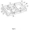
- multiwell filter plate 10is provided with posts 34 and 36 which fit respectively in holes 46 and 48 of multiwell receiver plate 29 when multiwell receiver plate 29 is positioned below multiwell filter plate 10,.
- posts 34 and 36can be positioned within holes 49 and 47 of feeding tray 28 when feeding tray 28 is positioned below multiwell filter plate 10 as shown in Figure 1A .
- Posts 34 and 36are positioned asymmetrically from each other in the direction of arrow 55 ( Figure 1A ) so that well 42a is always in the upper left hand position while well 42b is always in the lower right hand position shown in Figure 1A . By so positioning wells 42a and 42b, all the wells 42 in filter plate 10 can be identified by their position while preventing movement of multiwell filter plate 10 so that capillary pumping of liquid within wells 42 is prevented.
- filter plate 10is also exemplified with reference to Figs. 2A and 2B .
- the multiwell filter plate 10is positioned above multiwell receiver plate 29 which includes a multiplicity of wells 53, such as 96 wells.
- the multiwell receiver plate 29is positioned such that each membrane 43 ( Figure 2B ) of the wells 42 extends into only one well 53.
- Each of the wells 42has associated therewith an access hole 45 which permits access to a well 53 of a multiwell receiver plate 29 utilized during a sample assay step.
- the wells 53are shaped to accommodate wells 42 and to permit access thereto through holes 45.
- the multiwell filter plate 10can be provided with four legs 44 which fit into recesses 51 of multiwell receiver plate 29 thereby to provide mechanical stability of multiwell filter plate 10.
- the legsalso serve to position the membranes 43 to avoid contact with the bottom surfaces of the wells 53 thereby to prevent contact of the bottom surfaces of the wells 53 with the membranes 43.
- the feeding tray 28 utilized with the multiwell filler plate of this inventionincludes walls 12, 14, 16 and 18 and bottom surface 19 to house a nutrient medium.
- the bottom surfaceincludes two surface subsections 22 and 24 separated by drain path 21.
- the surface subsections 22 and 24are inclined downwardly from walls 12 and 16 in the direction exemplified by arrows 20 and 28 toward drain path 21.
- Drain path 21provides fluid flow from liquid introduction area 30 on the bottom surface to liquid drain area 32 as exemplified by arrow 33.
- each well 100 of a filter plate 101has an associated access hole 102, a permeable barrier layer 104 formed at the lower opening 106 of each well 100, a recess 108 and a shelf 110 formed adjacent the lower opening 106 and the lower portion of the recess 108.
- each wellis able to fit within a corresponding well 112 of a multiwell receiving plate 114.
- Figure 5shows a top down perspective view of the device described in Figure 4 along with access hole 116 which corresponds to the access hole 52 of Figure 1A .
- the shelf 110ais formed by conventional molding wherein the shelf 110a extends from the well wall 1 03a.
- the shelf 110bis formed by conventional molding wherein a portion of well wall 103b is recessed.
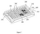
- an alternative feeding tray 200 utilized with the multiwell filler plate of this inventionis illustrated.
- This embodimentis provided with protrusions extending from the inner and supporting surface of the feeding tray a distance which permits their contact with the membranes of the wells of the multiwell filter plate.
- the protrusionsare posts 202 extend from surfaces 204 and 206 to a position where they can contact the membrane 43 of wells 42 of the embodiment of Figure 1 or the membrane 104 of the well 100 of the embodiment of Figure 4 .
- the purpose of this contactis to effect drainage of excess liquid from the bottom surface of the membrane 43 or 104 to the posts 202 and into the feeding tray 200.
- a post 202is positioned adjacent each well 42 or 100.
- the feeding tray 200also comprises inclined surfaces 204 and 206 which effect liquid flow in the directions of arrows 208 and 210 and in the direction of arrow 214 into the drainage area 212.
- a flat bottomed or other shaped feeding traymay equally be used if desired. Movement of a multiwell filter plate toward posts 202 can be effected by any conventional means.
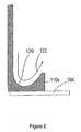
- the shelf 110ccan include a concave surface 120 which serves to direct liquid from a syringe, cannula, pipette and the like in the direction shown by arrow 122. This serves to reduce the pressure of the liquid from the syringe on membrane 104 thereby preserving the integrity of the membrane 104 and preserving the integrity of a cell layer on membrane 104.
Landscapes
- Health & Medical Sciences (AREA)
- Chemical & Material Sciences (AREA)
- Clinical Laboratory Science (AREA)
- General Health & Medical Sciences (AREA)
- Chemical Kinetics & Catalysis (AREA)
- Zoology (AREA)
- Wood Science & Technology (AREA)
- Life Sciences & Earth Sciences (AREA)
- Engineering & Computer Science (AREA)
- Bioinformatics & Cheminformatics (AREA)
- Hematology (AREA)
- Organic Chemistry (AREA)
- Analytical Chemistry (AREA)
- Biomedical Technology (AREA)
- Sustainable Development (AREA)
- Microbiology (AREA)
- Biochemistry (AREA)
- General Engineering & Computer Science (AREA)
- Genetics & Genomics (AREA)
- Biotechnology (AREA)
- Apparatus Associated With Microorganisms And Enzymes (AREA)
- Automatic Analysis And Handling Materials Therefor (AREA)
- Devices For Use In Laboratory Experiments (AREA)
Description
- This invention relates to a multiwell filter plate for retaining a liquid and which is utilized with a multiwell test apparatus suitable for promoting fluid interactions such as by growing cells in a nutrient medium within the wells. More particularly, this invention relates to such a multiwell filter plate of a multiwell test apparatus which permits adding or removing liquid from the feeding tray of a multiwell test apparatus without disturbing a material such as cells within the wells.
- At the present time, multiwell test apparatus for testing samples include a multiwell filter plate having a multiplicity of wells, a feeding tray, a multiwell receiver plate and a lid. The wells of the multiwell filter plate are formed of a tubular member with an open end to which is attached a membrane ,such as a microporous membrane. The tubular members can be inserted into the feeding tray containing a nutrient rich liquid medium so that cells in the wells can be attached to the membrane and grown thereon. The cells are fed as nutrients pass from the nutrient medium through the membrane and to the cells at a rate controlled by the concentration gradient of nutrients from the nutrient medium to the cells. The nutrient medium in the feeding tray is periodically replenished to maintain cell growth. It is desirable to effect replenishment of the nutrient medium quickly and in a manner which avoids damage to the membranes and the cells.
- After the desired level of cell growth on the membranes of the wells has been attained, the multiwell filer plate can be utilized in conventional assay methods. These assay methods generally are effected by positioning the membranes and cells on the multiwell filter plate into the wells of the multiwell receiver plate, such as a 96 well plate positioned below the multiwell filter plate or it just has to have the same number of wells in register with the cell/filter plate. The wells of the multiwell filter plate contain a liquid composition to be assayed. The composition to be assayed diffuses into the cells and then through the membrane into the bottom receiver plate. The resultant liquid product within the wells of the multiwell filter plate or in the wells of the multiwell receiver plate then is assayed to determine the capability of the composition being assayed to permeate the cell barrier.
- An important component in the drug discovery and development process is the determination of the oral absorption and bioavailability of new compounds. In order to perform this evaluation in a cost effective, high throughput and sensitive assay, it is ideal to use an invitro device with a multitude of wells, containing cells, a small amount of assay material and automation. Classically, the determination ofin vitro oral absorption characteristics is performed using a defined epithelium cell line and measuring the apparent transport rate of the drug across a monolayer of the cells. More recently it is possible to rank/order the passive transport rate of potential drug candidates using an artificial membrane barrier. The values generated from these invitro experiments are valuable methods for screening the most likely successful drug candidates long before the oral absorption rate are validated byin vivo measurements. A typical experiment for determining the drug absorption characteristics of a known or unknown chemical compound is performed as follows. The multiwell device is seeded with epithelium cells on top of the filter in a defined nutrients medium. The same medium is also added to the single well feeding tray, located below and in fluid contact with the device containing the cells. The cells are allowed to proliferate and differentiate over a number of days. The nutrient medium is periodically replaced with fresh medium to replenish exhausted nutrients and remove waste and dead cells. At the end of a growing time, the cells and multiwell device are gently washed with an isotonic buffer to remove protein and residual nutrient medium. At this time, the multiwell filter plate is transferred to the multiwell receiver plate and the chemicals to be assayed are introduced to either the compartment above the cell layer or below the cells and filter support in the multiwell receiver tray. The opposing chamber is filled with drug free buffer and the multiwell device is incubated for some period of time, typically at 37 degrees Centigrade with shaking. If multiple time points are desired, samples are taken from either compartment and buffer then is added to make up for the liquid removed. Typically, if samples are taken from the lower compartment, the filter plate must first be removed, thus risking contamination of the material in the wells. The amount of drug/chemical that is transported across the cell barrier can be determined by a variety of analytical methods, but typically is determined using LC-MS/MS (Liquid Chromatography-Mass Spectrometry-Mass Spectrometry).
- Accordingly, it would be desirable to provide a multiwell filter plate of a mulliwell test apparatus which facilitates replenishing a nutrient medium in a feeding tray quickly and in a manner which preserves the integrity of the membranes and cells on the membrane. In addition, it would be desirable to provide such a multiwell filter plate which can be utilized in conjunction with a multiwell receiver plate subsequent for use in conjunction with the feeding tray.
US5801055A discloses a multiwell test apparatus which comprises a multiwell insert plate provided to be received in a single well plate or tray. The insert plate includes a substantially planar top wall an a peripheral flange extending downwardly from the top wall. A plurality of wells are coupled to the top wall and extend downwardly therefrom. Each well includes an upper end defining an upper opening and a lower end defining a bottom opening. A side wall of each well generally frustoconically connects the upper and lower ends. A radial opening extends through the side wall at a portion of the upper end of each well. The lower end of each well includes an annular end face to which a semi-permeable microporous membrane is affixed. A plurality of wall openings extend through the top wall of the insert plate and respectively adjoin the radial openings in the wells, wherein the wall openings and the radial openings define a plurality of pipette openings which allow pipette access to the respective well and to a peripheral space adjacent the well when the insert plate is received in another multiwell receiver plate.- This invention will be described herein with reference to the growing and use of cells on a permeable barrier, such as a porous membrane or a glass fibrous mat, positioned and secured to the bottom of each of a multiplicity of wells. However, it is to be understood that the present invention need not be used in conjunction with cells. Other representative uses include filtration, dialysis or the like.
- The present invention provides a multiwell filter plate as defined in claim 1 comprising a multiplicity of wells each including a membrane for retaining a sample, such as cells on the membrane for use in a multiwell test apparatus. The multiwell filter plate is first used in conjunction with a feeding tray in a step wherein cell growth is promoted and then is used in conjunction with a multiwell receiver plate wherein sample testing is effected. The feeding tray promotes quick replenishment of the nutrient medium while avoiding damage to membranes secured to a multiplicity of wells or damage to cells positioned on the membranes. The feeding tray can include a flat or inclined bottom surface. The bottom surface is preferably inclined so that the nutrient medium will flow to a low point of the inclined bottom surface as the nutrient medium is removed through one or more access holes of the multiwell filter plate from the bottom surface of the feeding tray, preferably at the low point of the inclined bottom surface.
- The multiwell filter plate of this invention is provided with an input access hole or slot through which the nutrient medium is supplied to the feeding tray and is provided with a drainage access hole or slot through which the nutrient medium is removed from the feeding tray. The access holes permit insertion of a liquid handling device such as a syringe, cannula, pipette or the like therethrough, for introduction or drainage of the nutrient medium while avoiding the need for separating the multiwell filter plate from the feeding tray in order to replenish or supply nutrient medium to the feeding tray. Alternatively, the nutrient can be both removed and added through a single access hole at a low point of an inclined bottom support of a feeding tray. In a further alternative, the use of the filter plate having one or more openings providing access to the feeding tray may be used in conjunction with a flat bottomed feeding tray.
- The wells of the multiwell filter plate are shaped to form at least one shelf extending from a wall of the well and spaced apart from the membrane so that the shelf provides a support surface for an end of the liquid handling device such as a syringe, cannula, pipette or the like to prevent its contact with the permeable barrier, typically a membrane, and the growing cells. Additionally, the shelf serves as a deflector when media is injected into the well. The shelf allows the media to be added without disturbing the growing cells.
- The multiwell filter plate of this invention is used in a second step in conjunction with a multiwell receiver plate, the wells of which house a liquid that interacts with the membrane or cells within the wells of the multiwell filter tray. An access hole is positioned adjacent each well of the multiwell filter tray to provide direct access to the wells of the multiwell receiver plate positioned below the multiwell filter plate.
Figure1A is a top exploded view of a multiwell test apparatus utilizing the filter plate of this invention.Figure 1B is a partial cross-sectional view of the wells of the multiwell filter plate ofFigure 1A .Figure 2A is a top partial view of the multiwell filter plate of this invention positioned above a multiwell receiver plate.Figure 2B is a partial cross-sectional view of the multiwell filter plate and multiwell receiver plate.Figure 3 is a top view of a feeding tray which can be utilized with the multiwell filter plate of this invention.Figure 4 is a partial cross-sectional view of the multiwell filter plate and multiwell receiver plate.Figure 5 is a top view of a multiwell filter plate of this invention.Figures 6A and B are a partial cross-sectional view of a well of the multiwell filter plate of the present invention.Figure 7 is a top view of a single well receiver plate of this invention.Figure 8 is a partial cross-sectional view of a well of the multiwell filter plate of the present invention.- While the present invention is described with reference to effecting cell growth in a multiplicity of wells, it is to be understood that the present invention is applicable to manipulations involving access areas for introducing or removing a liquid to effect the desired processing, for example dialysis or diffusional separation while avoiding movement of membranes in the wells.
- Referring to
Figures 1A and 1B , themultiwell filter plate 10 of this invention comprises aplate 40 including a plurality ofwells 42, each of which is paired with anaccess hole 45. As shown inFigure 1B , each well 42 comprises atubular member 42a having a lower opening to which is secured amembrane 43 such as a microporous membrane. While the member is preferably tubular in shape, other shapes can also be used such as triangular, rectangular, square or hexagonal. Themultiwell filter plate 10 includes anaccess hole 50 which provides access to adrainage area 32 of feedingtray 28 from which liquid can be supplied to and/or drained from feedingtray 28. - Preferably, the nutrient medium can be replenished through a
separate access hole 52 infilter plate 10. Liquid nutrient composition can be drained from feedingtray 28 throughaccess hole 50. Replenishment and drainage can be effected with a conventional syringe apparatus. As shown in this embodiment, the feeding tray has an inclined bottom surface such that thedrainage area 32 is positioned at the lowest point of thebottom surface 70 of feedingtray 28 and complete drainage can be easily effected. Drainage and replenishment can be effected simultaneously without the need to movemultiwell filter plate 10 relative to feedingtray 28.Removable lid 56 is utilized to isolate thewells 42 from the atmosphere surrounding themultiwell filter plate 10 thereby to reduce evaporation of the nutrient medium and contamination of the well. It is evident that the nutrient medium can be added and removed through a single access hole at a low point of the inclined bottom surface. Separate areas for addition and removal effects a flushing action to improve the removal of nutrient medium to and from the feedingtray 28 of spent nutrient medium. - In an alternative arrangement (not shown) the feeding plate may have a flat bottom. Al other features described and shown in relation to
Figures 1A and 1B remain the same. - In the embodiment shown in
Figs. 2A and2B ,multiwell filter plate 10 is provided withposts holes multiwell receiver plate 29 whenmultiwell receiver plate 29 is positioned belowmultiwell filter plate 10,. Alternatively posts 34 and 36 can be positioned withinholes tray 28 when feedingtray 28 is positioned belowmultiwell filter plate 10 as shown inFigure 1A .Posts Figure 1A ) so that well 42a is always in the upper left hand position whilewell 42b is always in the lower right hand position shown inFigure 1A . By so positioningwells wells 42 infilter plate 10 can be identified by their position while preventing movement ofmultiwell filter plate 10 so that capillary pumping of liquid withinwells 42 is prevented. - The use of
filter plate 10 is also exemplified with reference toFigs. 2A and2B . As shown inFigs. 2A and2B , themultiwell filter plate 10 is positioned abovemultiwell receiver plate 29 which includes a multiplicity ofwells 53, such as 96 wells. In use, themultiwell receiver plate 29 is positioned such that each membrane 43 (Figure 2B ) of thewells 42 extends into only onewell 53. Each of thewells 42 has associated therewith anaccess hole 45 which permits access to a well 53 of amultiwell receiver plate 29 utilized during a sample assay step. Thewells 53 are shaped to accommodatewells 42 and to permit access thereto throughholes 45. Themultiwell filter plate 10 can be provided with fourlegs 44 which fit intorecesses 51 ofmultiwell receiver plate 29 thereby to provide mechanical stability ofmultiwell filter plate 10. The legs also serve to position themembranes 43 to avoid contact with the bottom surfaces of thewells 53 thereby to prevent contact of the bottom surfaces of thewells 53 with themembranes 43. - Referring to
Figure 3 , the feedingtray 28 utilized with the multiwell filler plate of this invention includeswalls bottom surface 19 to house a nutrient medium. The bottom surface includes twosurface subsections drain path 21. The surface subsections 22 and 24 are inclined downwardly fromwalls arrows drain path 21. Drainpath 21 provides fluid flow fromliquid introduction area 30 on the bottom surface toliquid drain area 32 as exemplified byarrow 33. - An alternative embodiment of the design described above is shown in
Figure 4 . In this embodiment, each well 100 of afilter plate 101 has an associatedaccess hole 102, apermeable barrier layer 104 formed at thelower opening 106 of each well 100, arecess 108 and ashelf 110 formed adjacent thelower opening 106 and the lower portion of therecess 108. As shown each well is able to fit within a corresponding well 112 of amultiwell receiving plate 114. Figure 5 shows a top down perspective view of the device described inFigure 4 along withaccess hole 116 which corresponds to theaccess hole 52 ofFigure 1A .- Referring to
Figure 6A , theshelf 110a is formed by conventional molding wherein theshelf 110a extends from the well wall 1 03a. - Referring to
Figure 6B , theshelf 110b is formed by conventional molding wherein a portion ofwell wall 103b is recessed. - Referring to
Figure 7 , analternative feeding tray 200 utilized with the multiwell filler plate of this invention is illustrated. This embodiment is provided with protrusions extending from the inner and supporting surface of the feeding tray a distance which permits their contact with the membranes of the wells of the multiwell filter plate. As shown, the protrusions areposts 202 extend fromsurfaces membrane 43 ofwells 42 of the embodiment ofFigure 1 or themembrane 104 of the well 100 of the embodiment ofFigure 4 . The purpose of this contact is to effect drainage of excess liquid from the bottom surface of themembrane posts 202 and into the feedingtray 200. This practice is commonly called "touch-off" in the field of pipetting and means to remove residual liquids/sample adhering to pipette tips. The shape of the protrusions may be varied so long as they provide the same function. Typical shapes include conical, pyramidal, rectangular and dimpled. Apost 202 is positioned adjacent each well 42 or 100. As shown, the feedingtray 200 also comprisesinclined surfaces arrows arrow 214 into thedrainage area 212. However, a flat bottomed or other shaped feeding tray may equally be used if desired. Movement of a multiwell filter plate towardposts 202 can be effected by any conventional means. - As shown in
Figure 8 , theshelf 110c can include aconcave surface 120 which serves to direct liquid from a syringe, cannula, pipette and the like in the direction shown byarrow 122. This serves to reduce the pressure of the liquid from the syringe onmembrane 104 thereby preserving the integrity of themembrane 104 and preserving the integrity of a cell layer onmembrane 104.
Claims (13)
- A multiwell filter plate (10,101) which comprises:a multiplicity of wells (42;100) extending from a plate (40), each of said wells (42;100) comprising(a) a hollow member (42a) having two openings (106) and extending from said plate (40) and(b) a permeable barrier (43;104) secured about one (106) of said openings extending from the plate (40);a first access hole (50,52;116) through said plate (40) for passing liquid through said plate (40) to effect contact of said liquid with all of said permeable barriers (43;104); anda set of second access holes (45;102) extending through said plate (40), each of said second access holes (43;102) positioned adjacent each one of said multiplicity of wells (42;100).
- The multiwell filter plate of claim 1 including a further access hole (50,52) for passing liquid through said plate (40) to remove liquid from contact with all of said barriers (43;104).
- The filter plate of claim 1 or 2, wherein said second access holes (45;102) are separated from the respective openings of the wells in the plate (40).
- The multiwell filter plate of any one of claims 1 to 3 including a plurality of legs (44) extending from a surface of said plate (40) from which said wells (42) extend and at a distance longer than the length of said hollow members (42a).
- The filter plate of any one of claims 1 to 4 further comprising a shelf (110;110a;110b;110c) extending inwardly from a wall (103a;103b) of the hollow member adjacent the porous membrane (104) secured about said opening (106).
- The filter plate of claim 5 wherein said shelf (110b) is formed by a recess in said wall (103b).
- The filter plate of claim 5 or 6 wherein said shelf (110c) has a top concave surface (120).
- A multiwell test apparatus comprising:a multiwell filter plate (10;101) of any one of claims 1 to 7; anda feeding tray (28;200) supporting said filter plate (10;101), said feeding tray having an inclined support surface (70) having a drainage area (32) from which liquid can be removed and an introduction area (30) into which liquid can be supplied, said inclined support surface (70) being inclined in a configuration to effect drainage of liquid from said introduction area (30) to said drainage area (32), and walls (12,14,16,18) surrounding said inclined surface (70) to enclose said inclined surface.
- The multiwell test apparatus of claim 8 wherein said inclined support surface (70) comprises two support surface subsections (22,24;204,206) each inclined from said walls (12,14,16,18) to a drainage path (21) connected to both of said support surface subsections (22,24;204,206).
- The multiwell test apparatus of claim 8 or 9 which includes a multiplicity of protrusions (202) extending from said support surface in a direction substantially the same as a direction said walls extend from said support surface, said protrusions (202) having a length which permits said walls to support said multi-well filter plate (10;101) and to permit contact of said protrusions (202) with each membrane of a well of said filter plate (10;101) when said filter plate is removed from support by said feed tray.
- The multiwell test apparatus of claim 10 wherein said protrusions (202) are selected from the group consisting of posts, pyramids, rectangles, dimples and cones.
- A multiwell test apparatus comprising:a multiwell filter plate (10;101) of any one of claims 1 to 7; anda multiwell receiver plate (29;114) supporting said multiwell filter plate (10;101), said multiwell receiver plate (29;114) having a plurality of non-circular wells (53;112) having a primary volume into which a membrane of one of said filter wells extends and a secondary volume capable of receiving a syringe extending through one of said second access holes (45).
- A multiwell test apparatus comprising:a multiwell filter plate (10;101) of any one of claims 1 to 7; anda feeding tray (28;200) supporting said filter plate (10;101), said feeding tray having a drainage area (32) from which liquid can be removed and an introduction area (30) into which liquid can be supplied, said first and further access hole (50,52) providing access to said drainage area (32) and introduction area (30), respectively.
Priority Applications (1)
| Application Number | Priority Date | Filing Date | Title |
|---|---|---|---|
| EP10190319AEP2286917A3 (en) | 2001-06-14 | 2002-06-11 | Access holes for feeding a multiwell filter plate |
Applications Claiming Priority (5)
| Application Number | Priority Date | Filing Date | Title |
|---|---|---|---|
| US29824401P | 2001-06-14 | 2001-06-14 | |
| US29826401P | 2001-06-14 | 2001-06-14 | |
| US298264P | 2001-06-14 | ||
| US298244P | 2001-06-14 | ||
| PCT/US2002/018403WO2002102962A2 (en) | 2001-06-14 | 2002-06-11 | Access holes for feeding a multiwell filter plate |
Related Child Applications (1)
| Application Number | Title | Priority Date | Filing Date |
|---|---|---|---|
| EP10190319.3Division-Into | 2010-11-08 |
Publications (2)
| Publication Number | Publication Date |
|---|---|
| EP1395645A2 EP1395645A2 (en) | 2004-03-10 |
| EP1395645B1true EP1395645B1 (en) | 2013-05-22 |
Family
ID=26970557
Family Applications (2)
| Application Number | Title | Priority Date | Filing Date |
|---|---|---|---|
| EP10190319AWithdrawnEP2286917A3 (en) | 2001-06-14 | 2002-06-11 | Access holes for feeding a multiwell filter plate |
| EP02732061.3AExpired - LifetimeEP1395645B1 (en) | 2001-06-14 | 2002-06-11 | Access holes for feeding a multiwell filter plate |
Family Applications Before (1)
| Application Number | Title | Priority Date | Filing Date |
|---|---|---|---|
| EP10190319AWithdrawnEP2286917A3 (en) | 2001-06-14 | 2002-06-11 | Access holes for feeding a multiwell filter plate |
Country Status (5)
| Country | Link |
|---|---|
| US (1) | US7135148B2 (en) |
| EP (2) | EP2286917A3 (en) |
| JP (2) | JP3907624B2 (en) |
| ES (1) | ES2409655T3 (en) |
| WO (1) | WO2002102962A2 (en) |
Cited By (1)
| Publication number | Priority date | Publication date | Assignee | Title |
|---|---|---|---|---|
| WO2025071696A1 (en)* | 2023-09-27 | 2025-04-03 | Emd Millipore Corporation | Well plate support |
Families Citing this family (28)
| Publication number | Priority date | Publication date | Assignee | Title |
|---|---|---|---|---|
| EP1397213B1 (en)* | 2001-06-14 | 2016-09-14 | EMD Millipore Corporation | Feeding tray for multiwell test apparatus |
| JP2005502861A (en)* | 2001-08-10 | 2005-01-27 | サイミックス テクノロジーズ, インコーポレイテッド | Apparatus and method for making and testing pre-formulations and system therefor |
| US20040120860A1 (en)* | 2001-12-21 | 2004-06-24 | Nikolaus Ingenhoven | Device and method for the transfer of liquid samples |
| US8277760B2 (en) | 2003-09-19 | 2012-10-02 | Applied Biosystems, Llc | High density plate filler |
| US7998435B2 (en) | 2003-09-19 | 2011-08-16 | Life Technologies Corporation | High density plate filler |
| US20060013984A1 (en)* | 2003-09-19 | 2006-01-19 | Donald Sandell | Film preparation for seal applicator |
| US20050232818A1 (en)* | 2003-09-19 | 2005-10-20 | Donald Sandell | Single sheet seal applicator and cartridge |
| US20060011305A1 (en)* | 2003-09-19 | 2006-01-19 | Donald Sandell | Automated seal applicator |
| US7407630B2 (en) | 2003-09-19 | 2008-08-05 | Applera Corporation | High density plate filler |
| US20050226780A1 (en)* | 2003-09-19 | 2005-10-13 | Donald Sandell | Manual seal applicator |
| EP1670944A4 (en)* | 2003-09-19 | 2012-12-05 | Life Technologies Corp | Microplates useful for conducting thermocycled nucleotide amplification |
| US7186548B2 (en)* | 2003-11-10 | 2007-03-06 | Advanced Pharmaceutical Sciences, Inc. | Cell culture tool and method |
| US7968061B2 (en) | 2004-10-18 | 2011-06-28 | Becton, Dickinson And Company | Microplate with dialysis membrane |
| WO2006131123A2 (en)* | 2005-06-10 | 2006-12-14 | Nunc A/S | Culture insert carrier, culture insert and culture insert system |
| US20060286003A1 (en)* | 2005-06-16 | 2006-12-21 | Desilets Kenneth G | Multi-well filter plate with shifted wells and U-bottom receiver plate |
| JP2011147403A (en)* | 2010-01-22 | 2011-08-04 | Hitachi High-Technologies Corp | Bacterial test apparatus and bacterial test method |
| US9200246B2 (en) | 2011-12-01 | 2015-12-01 | Acea Biosciences, Inc. | Co-culture device assembly |
| JP2014003922A (en)* | 2012-06-22 | 2014-01-16 | Sumitomo Bakelite Co Ltd | Positioning appliance |
| WO2014041488A1 (en)* | 2012-09-11 | 2014-03-20 | Centre Hospitalier Universitaire Vaudois | Conical multi-well filter plate |
| JP2016077186A (en)* | 2014-10-14 | 2016-05-16 | 大日本印刷株式会社 | Culture container and lower container |
| JP2017085899A (en)* | 2015-11-02 | 2017-05-25 | シンフォニアテクノロジー株式会社 | Culture container conveying apparatus |
| GB201614116D0 (en) | 2016-08-18 | 2016-10-05 | Vib Vzw And Univ Gent | Netwell assay plate system |
| GB2569095B (en)* | 2017-10-16 | 2020-06-17 | Wilkinson China Ltd | Heatproof carrier for food preparation and method |
| JP7074303B2 (en)* | 2018-03-05 | 2022-05-24 | 地方独立行政法人鳥取県産業技術センター | Microplate |
| USD920536S1 (en) | 2018-09-28 | 2021-05-25 | Becton, Dickinson And Company | Reagent plate |
| FR3106764B1 (en)* | 2020-01-31 | 2022-04-29 | Letat Francais Represente Par Le Mini De Linterieur | Device for analyzing biological solid elements and device for its implementation |
| US20230272327A1 (en)* | 2020-07-02 | 2023-08-31 | University Of Florida Research Foundation, Inc. | Perfusion-enabled bioreactor |
| EP4393598A1 (en)* | 2022-12-27 | 2024-07-03 | TECAN Trading AG | Temperature equalizing plate for a microplate reader and microplate reader with such a temperature equalizing plate |
Family Cites Families (16)
| Publication number | Priority date | Publication date | Assignee | Title |
|---|---|---|---|---|
| US5026649A (en)* | 1986-03-20 | 1991-06-25 | Costar Corporation | Apparatus for growing tissue cultures in vitro |
| US5108704A (en)* | 1988-09-16 | 1992-04-28 | W. R. Grace & Co.-Conn. | Microfiltration apparatus with radially spaced nozzles |
| US5141718A (en)* | 1990-10-30 | 1992-08-25 | Millipore Corporation | Test plate apparatus |
| US5650323A (en)* | 1991-06-26 | 1997-07-22 | Costar Corporation | System for growing and manipulating tissue cultures using 96-well format equipment |
| US5326533A (en)* | 1992-11-04 | 1994-07-05 | Millipore Corporation | Multiwell test apparatus |
| US5462874A (en)* | 1993-06-23 | 1995-10-31 | Wolf; Martin L. | Dialyzed multiple well tissue culture plate |
| US5707869A (en)* | 1994-06-28 | 1998-01-13 | Wolf; Martin L. | Compartmentalized multiple well tissue culture plate |
| JP3201965B2 (en)* | 1995-12-28 | 2001-08-27 | アロカ株式会社 | Sample container for reagent processing and biological tissue processing device |
| US5795775A (en)* | 1996-09-26 | 1998-08-18 | Becton Dickinson And Company | Culture vessel and assembly |
| US5972694A (en)* | 1997-02-11 | 1999-10-26 | Mathus; Gregory | Multi-well plate |
| US5801055A (en)* | 1997-09-10 | 1998-09-01 | Becton Dickinson And Company | Multi-well culture dish assembly |
| US5962250A (en) | 1997-10-28 | 1999-10-05 | Glaxo Group Limited | Split multi-well plate and methods |
| AU3865399A (en)* | 1998-04-23 | 1999-11-08 | Otter Coast Automation, Inc. | Method and apparatus for synthesis of libraries of organic compounds |
| US6309605B1 (en)* | 1999-05-05 | 2001-10-30 | Millipore Corporation | Well(s) containing filtration devices |
| EP1232792B1 (en) | 2001-02-20 | 2006-09-06 | F. Hoffmann-La Roche Ag | Linear cuvette array, a two-dimensional cuvette array built therewith and a system comprising such two-dimensional cuvette arrays |
| US7018588B2 (en)* | 2001-06-14 | 2006-03-28 | Millipore Corporation | Multiwell test apparatus |
- 2002
- 2002-06-11USUS10/166,871patent/US7135148B2/ennot_activeExpired - Lifetime
- 2002-06-11EPEP10190319Apatent/EP2286917A3/ennot_activeWithdrawn
- 2002-06-11WOPCT/US2002/018403patent/WO2002102962A2/enactiveApplication Filing
- 2002-06-11EPEP02732061.3Apatent/EP1395645B1/ennot_activeExpired - Lifetime
- 2002-06-11JPJP2003506417Apatent/JP3907624B2/ennot_activeExpired - Lifetime
- 2002-06-11ESES02732061Tpatent/ES2409655T3/ennot_activeExpired - Lifetime
- 2006
- 2006-11-28JPJP2006320048Apatent/JP3946242B2/ennot_activeExpired - Lifetime
Cited By (1)
| Publication number | Priority date | Publication date | Assignee | Title |
|---|---|---|---|---|
| WO2025071696A1 (en)* | 2023-09-27 | 2025-04-03 | Emd Millipore Corporation | Well plate support |
Also Published As
| Publication number | Publication date |
|---|---|
| US20020192119A1 (en) | 2002-12-19 |
| WO2002102962A2 (en) | 2002-12-27 |
| JP3946242B2 (en) | 2007-07-18 |
| JP2004521644A (en) | 2004-07-22 |
| JP2007089590A (en) | 2007-04-12 |
| US7135148B2 (en) | 2006-11-14 |
| EP1395645A2 (en) | 2004-03-10 |
| EP2286917A2 (en) | 2011-02-23 |
| JP3907624B2 (en) | 2007-04-18 |
| EP2286917A3 (en) | 2011-08-17 |
| ES2409655T3 (en) | 2013-06-27 |
| WO2002102962A3 (en) | 2003-04-03 |
Similar Documents
| Publication | Publication Date | Title |
|---|---|---|
| EP1395645B1 (en) | Access holes for feeding a multiwell filter plate | |
| US7166257B2 (en) | Multiwell test apparatus | |
| US7282362B2 (en) | Tray with protrusions | |
| EP3148700B1 (en) | Single column microplate system and carrier for analysis of biological samples | |
| EP0483620A2 (en) | Test plate apparatus | |
| US20030215940A1 (en) | Multi-well assembly for growing cultures in-vitro | |
| US7135149B2 (en) | Positioning pins for multiwell test apparatus | |
| EP1397213B1 (en) | Feeding tray for multiwell test apparatus | |
| ES2354965T3 (en) | POSITIONING AXIS FOR MULTIPOCILLO TESTING DEVICE. |
Legal Events
| Date | Code | Title | Description |
|---|---|---|---|
| PUAI | Public reference made under article 153(3) epc to a published international application that has entered the european phase | Free format text:ORIGINAL CODE: 0009012 | |
| 17P | Request for examination filed | Effective date:20030925 | |
| AK | Designated contracting states | Kind code of ref document:A2 Designated state(s):AT BE CH CY DE DK ES FI FR GB GR IE IT LI LU MC NL PT SE TR | |
| 17Q | First examination report despatched | Effective date:20100325 | |
| RAP1 | Party data changed (applicant data changed or rights of an application transferred) | Owner name:EMD MILLIPORE CORPORATION | |
| REG | Reference to a national code | Ref country code:DE Ref legal event code:R079 Ref document number:60244996 Country of ref document:DE Free format text:PREVIOUS MAIN CLASS: C12M0001000000 Ipc:B01L0003000000 | |
| GRAP | Despatch of communication of intention to grant a patent | Free format text:ORIGINAL CODE: EPIDOSNIGR1 | |
| RIC1 | Information provided on ipc code assigned before grant | Ipc:C12M 1/00 20060101ALI20121123BHEP Ipc:B01L 3/00 20060101AFI20121123BHEP Ipc:B01L 9/00 20060101ALI20121123BHEP | |
| RBV | Designated contracting states (corrected) | Designated state(s):DE ES FR GB IT | |
| GRAS | Grant fee paid | Free format text:ORIGINAL CODE: EPIDOSNIGR3 | |
| GRAA | (expected) grant | Free format text:ORIGINAL CODE: 0009210 | |
| AK | Designated contracting states | Kind code of ref document:B1 Designated state(s):DE ES FR GB IT | |
| REG | Reference to a national code | Ref country code:GB Ref legal event code:FG4D | |
| REG | Reference to a national code | Ref country code:ES Ref legal event code:FG2A Ref document number:2409655 Country of ref document:ES Kind code of ref document:T3 Effective date:20130627 | |
| REG | Reference to a national code | Ref country code:DE Ref legal event code:R096 Ref document number:60244996 Country of ref document:DE Effective date:20130718 | |
| PLBE | No opposition filed within time limit | Free format text:ORIGINAL CODE: 0009261 | |
| STAA | Information on the status of an ep patent application or granted ep patent | Free format text:STATUS: NO OPPOSITION FILED WITHIN TIME LIMIT | |
| 26N | No opposition filed | Effective date:20140225 | |
| REG | Reference to a national code | Ref country code:DE Ref legal event code:R097 Ref document number:60244996 Country of ref document:DE Effective date:20140225 | |
| REG | Reference to a national code | Ref country code:FR Ref legal event code:PLFP Year of fee payment:15 | |
| REG | Reference to a national code | Ref country code:FR Ref legal event code:PLFP Year of fee payment:16 | |
| REG | Reference to a national code | Ref country code:FR Ref legal event code:PLFP Year of fee payment:17 | |
| PGFP | Annual fee paid to national office [announced via postgrant information from national office to epo] | Ref country code:FR Payment date:20210513 Year of fee payment:20 Ref country code:DE Payment date:20210518 Year of fee payment:20 Ref country code:IT Payment date:20210511 Year of fee payment:20 | |
| PGFP | Annual fee paid to national office [announced via postgrant information from national office to epo] | Ref country code:GB Payment date:20210519 Year of fee payment:20 | |
| PGFP | Annual fee paid to national office [announced via postgrant information from national office to epo] | Ref country code:ES Payment date:20210705 Year of fee payment:20 | |
| REG | Reference to a national code | Ref country code:DE Ref legal event code:R071 Ref document number:60244996 Country of ref document:DE | |
| REG | Reference to a national code | Ref country code:GB Ref legal event code:PE20 Expiry date:20220610 | |
| PG25 | Lapsed in a contracting state [announced via postgrant information from national office to epo] | Ref country code:GB Free format text:LAPSE BECAUSE OF EXPIRATION OF PROTECTION Effective date:20220610 | |
| REG | Reference to a national code | Ref country code:ES Ref legal event code:FD2A Effective date:20220805 | |
| PG25 | Lapsed in a contracting state [announced via postgrant information from national office to epo] | Ref country code:ES Free format text:LAPSE BECAUSE OF EXPIRATION OF PROTECTION Effective date:20220612 |