EP1392149B1 - Driver alertness monitoring system - Google Patents
Driver alertness monitoring systemDownload PDFInfo
- Publication number
- EP1392149B1 EP1392149B1EP02728004AEP02728004AEP1392149B1EP 1392149 B1EP1392149 B1EP 1392149B1EP 02728004 AEP02728004 AEP 02728004AEP 02728004 AEP02728004 AEP 02728004AEP 1392149 B1EP1392149 B1EP 1392149B1
- Authority
- EP
- European Patent Office
- Prior art keywords
- movement characteristic
- driver
- trace
- motor vehicle
- driver initiated
- Prior art date
- Legal status (The legal status is an assumption and is not a legal conclusion. Google has not performed a legal analysis and makes no representation as to the accuracy of the status listed.)
- Expired - Lifetime
Links
Images


Classifications
- B—PERFORMING OPERATIONS; TRANSPORTING
- B60—VEHICLES IN GENERAL
- B60K—ARRANGEMENT OR MOUNTING OF PROPULSION UNITS OR OF TRANSMISSIONS IN VEHICLES; ARRANGEMENT OR MOUNTING OF PLURAL DIVERSE PRIME-MOVERS IN VEHICLES; AUXILIARY DRIVES FOR VEHICLES; INSTRUMENTATION OR DASHBOARDS FOR VEHICLES; ARRANGEMENTS IN CONNECTION WITH COOLING, AIR INTAKE, GAS EXHAUST OR FUEL SUPPLY OF PROPULSION UNITS IN VEHICLES
- B60K28/00—Safety devices for propulsion-unit control, specially adapted for, or arranged in, vehicles, e.g. preventing fuel supply or ignition in the event of potentially dangerous conditions
- B60K28/02—Safety devices for propulsion-unit control, specially adapted for, or arranged in, vehicles, e.g. preventing fuel supply or ignition in the event of potentially dangerous conditions responsive to conditions relating to the driver
- B60K28/06—Safety devices for propulsion-unit control, specially adapted for, or arranged in, vehicles, e.g. preventing fuel supply or ignition in the event of potentially dangerous conditions responsive to conditions relating to the driver responsive to incapacity of driver
- B60K28/066—Safety devices for propulsion-unit control, specially adapted for, or arranged in, vehicles, e.g. preventing fuel supply or ignition in the event of potentially dangerous conditions responsive to conditions relating to the driver responsive to incapacity of driver actuating a signalling device
- G—PHYSICS
- G08—SIGNALLING
- G08B—SIGNALLING OR CALLING SYSTEMS; ORDER TELEGRAPHS; ALARM SYSTEMS
- G08B21/00—Alarms responsive to a single specified undesired or abnormal condition and not otherwise provided for
- G08B21/02—Alarms for ensuring the safety of persons
- G08B21/06—Alarms for ensuring the safety of persons indicating a condition of sleep, e.g. anti-dozing alarms
- B—PERFORMING OPERATIONS; TRANSPORTING
- B60—VEHICLES IN GENERAL
- B60W—CONJOINT CONTROL OF VEHICLE SUB-UNITS OF DIFFERENT TYPE OR DIFFERENT FUNCTION; CONTROL SYSTEMS SPECIALLY ADAPTED FOR HYBRID VEHICLES; ROAD VEHICLE DRIVE CONTROL SYSTEMS FOR PURPOSES NOT RELATED TO THE CONTROL OF A PARTICULAR SUB-UNIT
- B60W2520/00—Input parameters relating to overall vehicle dynamics
- B60W2520/10—Longitudinal speed
- B60W2520/105—Longitudinal acceleration
- B—PERFORMING OPERATIONS; TRANSPORTING
- B60—VEHICLES IN GENERAL
- B60W—CONJOINT CONTROL OF VEHICLE SUB-UNITS OF DIFFERENT TYPE OR DIFFERENT FUNCTION; CONTROL SYSTEMS SPECIALLY ADAPTED FOR HYBRID VEHICLES; ROAD VEHICLE DRIVE CONTROL SYSTEMS FOR PURPOSES NOT RELATED TO THE CONTROL OF A PARTICULAR SUB-UNIT
- B60W2540/00—Input parameters relating to occupants
- B60W2540/18—Steering angle
Definitions
- the present inventionrelates to alertness monitoring for drivers of motor vehicles.
- Embodiments of the present inventionseek to provide an improved methodology and system for monitoring the alertness of drivers of motor vehicles.
- a methodology for determining the alertness of a driver of a motor vehicleincluding:
- the at least one characteristic of driver initiated movementsis extent.
- the at least one characteristics of non-driver initiated movementsis extent.
- extent of driver initiated movementsincludes at least one of:
- extent of non-driver initiated movementsincludes at least one of:
- the sensing at least one characteristic of driver initiated movements of at least one part of a motor vehicle and the sensing at least one characteristic of non-driver initiated movements of at least one part of a motor vehicleinclude sensing at least one first movement characteristic and sensing at least one second movement characteristic of the motor vehicle.
- the at least one first movement characteristicincludes a steering wheel movement characteristic and the at least one second movement characteristic includes a road wheel movement characteristic.
- the at least one first movement characteristic and the at least one second movement characteristicinclude movement characteristics of first and second locations along a steering assembly extending from a steering wheel to at least one road wheel of the motor vehicle.
- the at least one first movement characteristicincludes a steering assembly movement characteristic and the at least one second movement characteristic includes a vehicle body movement characteristic.
- the at least one first movement characteristicincludes a steering assembly movement characteristic and the at least one second movement characteristic includes a vehicle chassis movement characteristic.
- the fust and second locationsare located respectively at or upstream of and at or downstream of a power steering unit forming part of the steering assembly.
- the first locationis at a steering wheel forming part of the steering assembly.
- the at least one first movement characteristicis angular displacement of the steering wheel; and the at least one second movement characteristic is a steering angle of at least one road wheel.
- the at least one first movement characteristicis displacement; and the at least one second movement characteristic is displacement.
- the at least one first movement characteristicis displacement; and the at least one second movement characteristic is acceleration in at least one direction.
- the at least one first movement characteristicis displacement; and the at least one second movement characteristic is acceleration in at least one direction.
- determiningalso employs the speed of the vehicle.
- the driver initiated movement sensorsensing at least one characteristic of driver initiated movements of at least one part of a motor vehicle and the non-driver initiated movement sensor sensing at least one characteristic of non-driver initiated movements of at least one part of a motor vehicle include a first sensor, sensing at least one first movement characteristic and a second sensor sensing at least one second movement characteristic of the motor vehicle.
- the systemalso includes a driver alertness alarm, responsive to an alarm from the driver alertness determiner for providing an alarm to a driver deemed not to be sufficiently alert.
- a driver alertness alarmresponsive to an alarm from the driver alertness determiner for providing an alarm to a driver deemed not to be sufficiently alert.
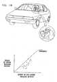
- FIGs. 1A and 1Bare simplified pictorial illustrations of a system and methodology for determining the alertness of a driver of a motor vehicle in accordance with a preferred embodiment of the present invention, respectively illustrating operation when a driver is alert and when a driver is not alert.
- a determination of the alertness of the driveris made based on a statistical relationship between at least one characteristic of driver initiated movements of at least one part of a motor vehicle and at least one characteristic of non-driver initiated movements of at least one part of a motor vehicle.
- a typical driver initiated movementincludes controlled movements of the motor vehicle, as for example by the driver turning the steering wheel.
- a typical non-driver initiated movements of the motor vehicleincludes uncontrolled movements of the motor vehicle, as for example by the car encountering an uneven section of the road, a gust or unbalanced vehicle wheels.
- the at least one characteristic of both driver initiated movements and of non-driver initiated movementsis extent.
- extentwhen used with “driver initiated motions” and “non-driver initiated motions”, is intended to convey measures of such motions. This measure may be derived in one or more different ways.
- extentmay be one or more of at least the following parameters for driver initiated movements:
- extentmay be one or more of at least the following parameters for non-driver initiated movements:
- magnitudeas used in the present application may refer to the amount of movement, irrespective of whether that movement is linear movement, angular movement or a combination thereof. Additionally, the term “magnitude” as used in the present application may also refer to a mathematical combination of the movement and another parameter, such as the vehicle speed.
- the "THRESHOLD" lines shown in Figs. 1A and 1Bdefine a predetermined relationship between driver initiated movements and non-driver initiated movements and shows the minimum extent of the driver initiated movements expected for the corresponding extent of non-driver initiated movements, which may be typically measured for a series of alert drivers or, alternatively may be typically established for specific alert drivers.
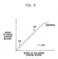
- the thresholdis preferably determined by correlating a statistically valid sampling of the results of the measuring the driver alertness, see for example the data presented in Fig. 5, with acceptable levels of driver alertness as measured by external means, such as visual records of the appearance of the driver or outputs of various biometric sensors.
- external meanssuch as visual records of the appearance of the driver or outputs of various biometric sensors.
- a thresholdis determined or selectable, which does not fail to provide an alarm when the driver is not sufficiently alert.
- operation of a motor vehicle by an alert driveris preferably characterized in that for at least a predetermined majority of a multiplicity of different time periods, a metric of the extent of driver initiated movements at least equals a corresponding metric of the extent of non-driver initiated movements.
- Fig. 1Bshows that corresponding operation of a motor vehicle by an non-alert driver is preferably characterized in that for at least a predetermined majority of a multiplicity of different time periods, a metric of the extent of driver initiated movements does not at least equal a corresponding metric of the extent of non-driver initiated movements.
- driver initiated motionsshould increase generally correspondingly.
- Fig. 2is a simplified pictorial illustration of a steering assembly and part of a chassis of a typical motor vehicle, illustrating a plurality of locations therealong where measurements of motion may be made in accordance with a preferred embodiment of the present invention.
- a conventional steering assembly 102including a steering wheel 104, a steering wheel shaft 106, connecting the steering wheel to a power steering unit 108, as well as right and left linkages 110 and 112 which connect the power steering unit to road wheels 114 and 116, respectively.
- the present inventionmay also be used with motor vehicles, which do not include a power steering unit 108.
- a driver alertness determining systemincluding a computation unit 120 which receives inputs from one or more angular motion sensors, preferably including a first angular motion sensor 122 disposed adjacent steering wheel shaft 106 at the steering wheel side thereof, a second angular motion sensor 124 disposed adjacent steering wheel shaft 106 at the power steering unit side thereof, a third angular motion sensor 126 disposed adjacent one of linkages 110 and 112, a fourth angular motion sensor 128 disposed adjacent a road wheel 114 or 116 and an acceleration sensor 130 mounted on a chassis portion 132 thereof.
- angular motion sensorspreferably including a first angular motion sensor 122 disposed adjacent steering wheel shaft 106 at the steering wheel side thereof, a second angular motion sensor 124 disposed adjacent steering wheel shaft 106 at the power steering unit side thereof, a third angular motion sensor 126 disposed adjacent one of linkages 110 and 112, a fourth angular motion sensor 128 disposed adjacent a road wheel 114 or 116 and an acceleration sensor 130 mounted on a
- Computation unit 120also preferably receives an input from a vehicle speed sensor 134 and provides a driver sensible output via a driver alertness alarm 136, which may be any suitable alarm such as a tactile, visual, audio or audiovisual alarm.
- inputsare received from two of the angular motion sensors, one adjacent the road wheels and one adjacent the steering wheel.
- an input from the acceleration sensor 130 in combination with one or more inputs from angular motion sensorsmay be employed.
- Fig. 3Ais a simplified flow chart illustrating the functionality of Figs. 1A and 1B in accordance with one preferred embodiment of the present invention.
- data from a road wheel influenced displacement sensorsuch as either of sensors 126 and 128, is normalized, at block 200, preferably to eliminate variations in measurements resulting from differences in the magnitudes of motion sensed by different sensors.
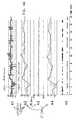
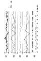
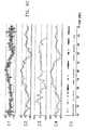
- Typical normalized data from the road wheel sensor 128 (Fig. 2) as a function of timeappear as a solid line in trace A1 of Fig. 4A, trace B1 of Fig. 4B and trace C1 of Fig. 4C.
- displacementrefers to either or both of linear and angular displacements.
- sensed displacementis angular displacement.
- road wheel displacementeither or both of angular displacement of the road wheel itself and linear displacement of elements coupled thereto may be sensed.
- the output of block 200is then filtered, at block 202, to remove noise, which in this case preferably includes all signal components having frequencies in excess of approximately 10 Hz.
- Typical normalized and filtered data from the road wheel sensor 128 (Fig. 2) as a function of timeappear as a solid line in trace A2 of Fig. 4A, trace B2 of Fig. 4B and trace C2 of Fig. 4C.
- the output of block 202is split into high and low frequency components, preferably above and below 4 Hz, as indicated in block 204.
- the high frequency component of typical normalized and filtered data from the road wheel sensor 128 (Fig. 2)appears as trace A3 of Fig. 4A, trace B3 of Fig. 4B and trace C3 of Fig. 4C.
- the high frequency componentnamely, the component above 4 Hz
- the component below 4 Hzmay include both driver initiated movements and non-driver initiated movements.
- the high frequency component output of block 204is further processed, together with the data of the vehicle sensor 134 (Fig. 2), as indicated in a block 206, to further characterize this component.
- the functionality of block 206may include one or more of calculating RMS values, average values, and standard deviations of the high frequency component, typically coupled with the data from the vehicle speed sensor 134 (Fig. 2), over successive time periods, three of which are represented by respective Figs. 4A, 4B and 4C.
- the output of block 206is employed to determine the extent of non-driver initiated motion, as indicated in a block 208.
- the low frequency component output of block 204is further processed as indicated in a block 210, as is described hereinbelow.
- Data from a steering wheel influenced angular displacement sensoris normalized, at block 212, preferably to eliminate variations in measurements resulting from differences in the magnitudes of the motion sensed by different sensors.
- Typical normalized data from the steering wheel sensor 122(Fig. 2) as a function of time, appear as a dashed line in trace A1 of Fig. 4A, trace B1 of Fig. 4B and trace C 1 of Fig. 4C.
- the output of block 212is then filtered, at block 214, to remove noise, which in this case preferably includes all signal components having frequencies in excess of approximately 10 Hz.
- the output of block 214is preferably supplied to block 210, which is operative to determine the sign of the phase difference between the output of block 214 and the output of block 204, which are respectively represented by the dashed and solid lines in trace A4 of Fig. 4A, trace B4 of Fig. 4B and trace C4 of Fig. 4C for each of a multiplicity of discrete time durations.
- This phase differenceis defined to be positive, when the output of block 214, representing the steering wheel influenced motion, leads the output of block 204, representing the low frequency component of the road wheel influenced motion.
- the relevant time duration to which that data relatesis indicated, at block 216, to be driver initiated motion duration, indicated by a relatively thick line in trace A5 of Fig. 4A, trace B5 of Fig. 4B and trace C5 of Fig. 4C.
- the data representing driver initiated motionis then analyzed, at block 218, typically to determine the frequency of occurrence of driver initiated motions, which is an indication of the extent of driver initiated motions. Alternatively or additionally to determining the frequency of occurrence of driver initiated motions, any other suitable metric of the extent of driver initiated motions may be employed.
- the frequency of occurrence of driver initiated motionsmay be determined by counting the number of extrema points in the dashed line appearing in trace A4 of Fig. 4A, trace B4 of Fig. 4B and trace C4 of Fig. 4C during the driver initiated motion durations corresponding to the relatively thick lines in trace A5 of Fig. 4A, trace B5 of Fig. 4B and trace C5 of Fig. 4C. These extrema points are indicated by circles drawn on the relatively thick line in trace A5 of Fig. 4A, trace B5 of Fig. 4B and trace C5 of Fig. 4C.
- the relevant time duration to which that data relatesis indicated, at block 220 to be non-driver initiated motion duration, indicated by a relatively thin line in trace A5 of Fig. 4A, trace B5 of Fig. 4B and trace C5 of Fig. 4C.
- the data representing non-driver initiated motionis then analyzed, at block 222, in order to further characterize this data.
- the functionality of block 222may include one or more of calculating RMS values, average values, and standard deviations of the low frequency component, typically coupled with the data of the vehicle speed sensor (Fig. 2), over successive time periods, three of which are represented by respective Figs. 4A, 4B and 4C.
- the output of block 222is supplied to block 208 along with the output from block 206 in order to determine the extent of non-driver initiated motion.
- the functionality of block 208may be summarized as providing a metric indicating the level of non-driver initiated motion over successive time periods, three of which are represented by respective Figs. 4A, 4B and 4C.
- the level of non-driver initiated motionmay be expressed in a number of possible ways, such as a linear or non-linear combination of low frequency and high frequency data, which reflects one or both of magnitude of such motion and frequency of direction change of such motion.
- a linear combination of the low frequency and high frequency datais employed and reflects both magnitude and frequency of direction change.
- the outputs of blocks 208 and 218are employed in a block 224 to determine whether a driver meets alertness criteria, as will be described hereinbelow with reference to Figs. 5 and 6.
- Fig. 3Bis a simplified flow chart illustrating the functionality of Figs. 1A and 1B in accordance with another preferred embodiment of the present invention.
- the embodiment of Fig. 3Bdiffers from that of Fig. 3A in that the embodiment of Fig. 3B does not separate or separately employ the high frequency portion of the output of a road wheel displacement sensor.
- data from a road wheel influenced displacement sensoris normalized, at block 300, preferably to eliminate variations in measurements resulting from differences in the magnitudes of motion sensed by different sensors.
- Typical normalized data from the road wheel sensor 128 (Fig. 2) as a function of timeappear as a solid line in trace A1 of Fig. 4A, trace B1 of Fig. 4B and trace C1 of Fig. 4C.
- the output of block 300is then filtered, at block 302, to remove noise and other irrelevant data, which in this case preferably includes all signal components having frequencies in excess of approximately 4 Hz.
- the output of block 302is further processed as indicated in a block 310, as is described hereinbelow.
- Data from a steering wheel influenced angular displacement sensoris normalized, at block 312, preferably to eliminate variations in measurements resulting from differences in the magnitudes of motion sensed by different sensors.
- Typical normalized data from the steering wheel sensor 122(Fig. 2) as a function of time, appear as a dashed line in trace A1 of Fig. 4A, trace B1 of Fig. 4B and trace C1 of Fig. 4C.
- the output of block 312is then filtered, at block 314, to remove noise, which in this case preferably includes all signal components having frequencies in excess of approximately 4 Hz.
- Typical normalized and filtered data from sensor the steering wheel 122 (Fig. 2) as a function of timeappear as a dashed line in trace A2 of Fig. 4A, trace B2 of Fig. 4B and trace C2 of Fig. 4C.
- the output of block 314is preferably supplied to block 310, which is operative to determine the sign of the phase difference between the output of block 314 and the output of block 302, which are respectively represented by the dashed and solid lines in trace A4 of Fig. 4A, trace B4 of Fig. 4B and trace C4 of Fig. 4C for each of a multiplicity of discrete time durations.
- This phase differenceis defined to be positive, when the output of block 314, representing the steering wheel influenced motion, leads the output of block 302, representing the road wheel influenced motion.
- the relevant time duration to which that data relatesis indicated, at block 316, to be driver initiated motion duration, indicated by a relatively thick line in trace A5 of Fig. 4A, trace B5 of Fig. 4B and trace C5 of Fig. 4C.
- the data representing driver initiated motionis then analyzed, at block 318, typically to determine the frequency of occurrence of driver initiated motions, which is an indication of the extent of driver initiated motions. Alternatively or additionally to determining the frequency of occurrence of driver initiated motions, any other suitable metric of the extent of driver initiated motions may be employed.
- the frequency of occurrence of driver initiated motionsmay be determined by counting the number of extrema points in the dashed line appearing in trace A4 of Fig. 4A, trace B4 of Fig. 4B and trace C4 of Fig. 4C during the driver initiated motion durations corresponding to the relatively thick lines in trace A5 of Fig. 4A, trace B5 of Fig. 4B and trace C5 of Fig. 4C. These extrema points are indicated by circles drawn on the relatively thick line in trace A5 of Fig. 4A, trace B5 of Fig. 4B and trace C5 of Fig. 4C.
- the relevant time duration to which that data relatesis indicated, at block 320 to be non-driver initiated motion duration, indicated by a relatively thin line in trace A5 of Fig. 4A, trace B5 of Fig. 4B and trace C5 of Fig. 4C.
- the data representing non-driver initiated motionis then analyzed, at block 322, in order to further characterize this data.
- the functionality of block 322may include one or more of calculating RMS values, average values, and standard deviations of the low frequency component, typically coupled with the data of the vehicle speed sensor 134 (Fig. 2), over successive time periods, three of which are represented by respective Figs. 4A, 4B and 4C.
- the output of block 322is supplied to block 308 in order to determine the extent of non-driver initiated motion.
- the functionality of block 308may be summarized as providing a metric indicating the level of non-driver initiated motion over successive time periods, three of which are represented by respective Figs. 4A, 4B and 4C.
- the level of non-driver initiated motionmay be expressed in a number of possible ways, such as a linear or non-linear combination of data, which reflects one or both of magnitude of such motion and frequency of direction change of such motion.
- a linear combination of the datais employed and reflects both magnitude and frequency of direction change.
- the outputs of blocks 308 and 318are employed in a block 324 to determine whether a driver meets alertness criteria, as will be described hereinbelow with reference to Figs. 5 and 6.
- Fig. 3Cis a simplified flow chart illustrating the functionality of Figs. 1A and 1B in accordance with still another preferred embodiment of the present invention.
- the embodiment of Fig. 3Cdiffers from that of Fig. 3A in that data from an accelerometer, such as the lateral component of data from an acceleration sensor 130 (Fig. 2) fixed to the chassis of a vehicle, is employed instead of data from a road wheel influenced displacement sensor.
- an accelerometersuch as the lateral component of data from an acceleration sensor 130 (Fig. 2) fixed to the chassis of a vehicle
- Fig. 2fixed to the chassis of a vehicle
- the data from both a road wheel influenced displacement sensor and from an accelerometermay be employed.
- a vertical component from an accelerometermay be employed to represent non-driver initiated motion.
- data from an accelerometeris normalized, at block 400, preferably to eliminate variations in measurements resulting from differences in the magnitudes and dimensions of motions sensed by different sensors.
- the normalized data from the lateral component of the output of acceleration sensor 130 (Fig. 2) as a function of timeappear as a solid line in trace A1 of Fig. 4A, trace B1 of Fig. 4B and trace C1 of Fig. 4C.
- the output of block 400is then filtered, at block 402, to remove noise, which in this case preferably includes all signal components having frequencies in excess of approximately 10 Hz.
- noisewhich in this case preferably includes all signal components having frequencies in excess of approximately 10 Hz.
- the output of block 402is split into high and low frequency components, preferably above and below 4 Hz, as indicated in block 404.
- the high frequency component output of block 404is further processed, typically with the data from the vehicle speed sensor 134 (Fig. 2), as indicated in a block 406, to further characterize this component.
- the functionality of block 406may include one or more of calculating RMS values, average values, and standard deviations of the high frequency component, typically with the data from the vehicle speed sensor 134 (Fig. 2), over successive time periods, three of which are represented by respective Figs. 4A, 4B and 4C.
- a vertical component of the output of acceleration sensor 130may also be employed in block 406.
- the output of block 406is employed to determine the extent of non-driver initiated motion, as indicated in a block 408.
- the low frequency component output of block 404is further processed as indicated in a block 410, as is described hereinbelow.
- Data from a steering wheel influenced angular displacement sensoris normalized, at block 412, preferably to eliminate variations in measurements resulting from differences in the magnitudes of motion sensed by different sensors.
- Typical normalized data from the steering wheel sensor 122(Fig. 2) as a function of time, appear as a dashed line in trace A1 of Fig. 4A, trace B1 of Fig. 4B and trace C1 of Fig. 4C.
- the output of block 412is then filtered, at block 414, to remove noise, which in this case preferably includes all signal components having frequencies in excess of approximately 10 Hz.
- Typical normalized and filtered data from the steering wheel sensor 122 (Fig. 2) as a function of timeappear as a dashed line in trace A2 of Fig. 4A, trace B2 of Fig. 4B and trace C2 of Fig. 4C.
- the output of block 414is preferably supplied to block 410, which is operative to determine the sign of the phase difference between the output of block 414 and the output of block 404, which are respectively represented by the dashed and solid lines in trace A4 of Fig. 4A, trace B4 of Fig. 4B and trace C4 of Fig. 4C for each of a multiplicity of discrete time durations.
- This phase differenceis defined to be positive, when the output of block 414, representing the steering wheel influenced motion, leads the output of block 404, representing the low frequency component of the road wheel influenced motion.
- the relevant time duration to which that data relatesis indicated, at block 416, to be driver initiated motion duration, indicated by a relatively thick line in trace A5 of Fig. 4A, trace B5 of Fig. 4B and trace C5 of Fig. 4C.
- the data representing driver initiated motionis then analyzed, at block 418, typically to determine the frequency of occurrence of driver initiated motions, which is an indication of the extent of driver initiated motions. Alternatively or additionally to determining the frequency of occurrence of driver initiated motions, any other suitable metric of the extent of driver initiated motions may be employed.
- the frequency of occurrence of driver initiated motionsmay be determined by counting the number of extrema points in the dashed line appearing in trace A4 of Fig. 4A, trace B4 of Fig. 4B and trace C4 of Fig. 4C during the driver initiated motion durations corresponding to the relatively thick lines in trace A5 of Fig. 4A, trace B5 of Fig. 4B and trace C5 of Fig. 4C. These extrema points are indicated by circles drawn on the relatively thick line in trace A5 of Fig. 4A, trace B5 of Fig. 4B and trace C5 of Fig. 4C.
- the relevant time duration to which that data relatesis indicated, at block 420 to be non-driver initiated motion duration, indicated by a relatively thin line in trace A5 of Fig. 4A, trace B5 of Fig. 4B and trace C5 of Fig. 4C.
- the data representing non-driver initiated motionis then analyzed, at block 422, in order to further characterize this data.
- the functionality of block 422may include one or more of calculating RMS values, average values, and standard deviations of the low frequency component, typically with the data from the vehicle speed sensor 134 (Fig. 2), over successive time periods, three of which are represented by respective Figs. 4A, 4B and 4C.
- the output of block 422is supplied to block 408 along with the output from block 406 in order to determine the extent of non-driver initiated motion.
- the functionality of block 408may be summarized as providing a metric indicating the level of non-driver initiated motion over successive time periods, three of which are represented by respective Figs. 4A, 4B and 4C.
- the level of non-driver initiated motionmay be expressed in a number of possible ways, such as a linear or non-linear combination of low frequency and high frequency data, which reflects one or both of magnitude of such motion and frequency of direction change of such motion.
- a linear combination of the low frequency and high frequency datais employed and reflects both magnitude and frequency of direction change.
- the outputs of blocks 408 and 418are employed in a block 424 to determine whether a driver meets alertness criteria, as will be described hereinbelow with reference to Figs. 5 and 6.
- the output of acceleration sensor 130may be employed in place of or in addition to the output of a road-wheel influenced angular displacement sensor.
- Figs. 5 and 6illustrate utilization of determinations of extent of driver initiated and non-driver initiated motions for determining driver alertness.
- the Threshold Lineis initially determined as discussed hereinabove (step 600, Fig. 6).
- the extent of driver initiated motion and the extent of non-driver initiated motionare plotted in "Extent Space" (step 602, Fig. 6).
- Each such time periodis represented by a single point in "Extent Space”.
- a point 550represents the extent of driver initiated motion and the extent of non-driver initiated motion for the time period represented by Fig. 4A.
- the extent of driver initiated motionsis preferably derived from the frequency of their occurrence, as exemplified by the number of circles appearing in traces A5, B5 and C5, respectively in Figs. 4A, 4B and 4C.
- the extent of non-driver initiated motionsis preferably derived from the amplitude of the high frequency component of the non-driver initiated motions, as exemplified by the amplitudes appearing in traces A3, B3 and C3, typically combined with the amplitude of the low frequency component of the non-driver initiated motions taken together with other data relating thereto, such as the frequency of occurrence.
- the extent of non-driver initiated motionsis preferably derived from the amplitude of the low frequency component of the non-driver initiated motions taken together with other data relating thereto, such as the frequency of occurrence.
- point 560represents the extent of driver initiated motion and the extent of non-driver initiated motion for the time period represented by Fig. 4B and point 570 represents the extent of driver initiated motion and the extent of non-driver initiated motion for the time period represented by Fig. 4C.
- a threshold linethat differentiates couples of the extent of driver initiated motion and the extent of non-driver initiated motion for a given time period and being characteristic of driver alertness (above the line) and non-alertness (below the line).
- this threshold linemay be fixed or variable as the result of variations in one or more parameters, including, inter alia, vehicle speed, elapsed duration of trip, known or earlier determined driving characteristics of the driver, travel conditions and type of vehicle.
- a determination of driver alertness or non-alertnessmay be a cumulative determination based on a weighting of the points appearing above and below the threshold line, once a statistically acceptable sample is achieved (steps 604 and 606, Fig. 6). Alternatively or additionally, it may be a determination based on the change in the position of successive points relative to the threshold line and relative to each other as time passes.
- an appropriate alarm indicationis provided to the driver (step 608, Fig. 6), preferably via alarm 136 (Fig. 2).
Landscapes
- Business, Economics & Management (AREA)
- Engineering & Computer Science (AREA)
- General Physics & Mathematics (AREA)
- Physics & Mathematics (AREA)
- Emergency Management (AREA)
- Mechanical Engineering (AREA)
- Chemical & Material Sciences (AREA)
- Transportation (AREA)
- Combustion & Propulsion (AREA)
- Steering Control In Accordance With Driving Conditions (AREA)
- Control Of Driving Devices And Active Controlling Of Vehicle (AREA)
- Electric Propulsion And Braking For Vehicles (AREA)
- Auxiliary Drives, Propulsion Controls, And Safety Devices (AREA)
- Organic Low-Molecular-Weight Compounds And Preparation Thereof (AREA)
- Emergency Alarm Devices (AREA)
- Debugging And Monitoring (AREA)
- Testing Of Devices, Machine Parts, Or Other Structures Thereof (AREA)
Abstract
Description
- The present invention relates to alertness monitoring for drivers of motor vehicles.
- The following patents are believed to represent the current state of the art:
U.S, Patents 3,227,998 ;3,631,446 ;3,654,599 ;3,935,830 ;3,980,999 ;4,007,357 ;4,017,843 ;4,104,621 ;4,450,438 ;4,463,347 ;4,496,938 ;4,509,040 ;4,518,954 ;4,564,833 ;4,565,997 ;4,581,607 ;4,586,032 ;4,594,583 ;4,604,611 ;4,611,199 ;4,673,913 ;4,794,536 ;4,853,672 ;4,984,646 ;4,996,657 ;5,057,834 ;5,097,917 ;5,282,135 ;5,465,079 ;5,488,353 ;5,548,273 ;5,568,127 ;5,570,087 ;5,570,698 ;5,585,785 ;5,675,313 ;5,684,455 ;5,684,462 ;5,689,241 ;5,709,281 ;5,714,925 ;5,717,606 ;5,729,619 ;5,745,031 ;5,765,116 ;5,786,765 ;5,795,306 ;5,798,695 ;5,805,079 ;5,805,720 ;5,813,993 ;5,815,070 ;5,821,860 ;5,835,008 ;5,835,028 ;5,847,648 ;5,850,193 ;5,867,587 ;5,900,819 ;5,917,415 ;5,923,263 ;5,925,082 ;5,939,989 ;5,942,979 ;5,969,616 ;5,982,287 ;6,0231227 6,061,610 ;6,064,301 ;6,067,020 ;6,087,941 ;6,087,943 ;6,091,334 ;6,097,286 ;6,097,295 ;6,172,610 .- Particular aspects of the invention are set out in the appended claims.
- Embodiments of the present invention seek to provide an improved methodology and system for monitoring the alertness of drivers of motor vehicles.
- There is thus provided in accordance with an embodiment of the present invention a methodology for determining the alertness of a driver of a motor vehicle including:
- sensing at least one first movement characteristic of at least a first part of a motor vehicle;
- sensing at least one second movement characteristic of at least a second part of the motor vehicle ;
- employing at least one time relationship between the at least one first movement characteristic and the at least one second movement characteristic in order to sense and to distinguish between driver initiated movements and non-driver initiated movements; and
- determining the alertness of the driver of the motor vehicle based on at least one relationship between the driver initiated movements and the non-driver initiated movements.
- There is also provided in accordance with an embodiment of the present invention, a methodology for determining the alertness of a driver of a motor vehicle including:
- employing at least one time relationship between at least one first movement characteristic of at least a first part of a motor vehicle and at least one second movement characteristic of at least a second part of the motor vehicle in order to sense and to distinguish between driver initiated movements and non-driver initiated movements; and
- determining the alertness of the driver of the motor vehicle based on at least one relationship between the driver initiated movements and the non-driver initiated movements.
- There is additionally provided in accordance with an embodiment of the present invention a methodology for determining the alertness of a driver of a motor vehicle including:
- sensing at least one first movement characteristic of at least a first part of a motor vehicle;
- sensing at least one second movement characteristic of at least a second part of a motor vehicle: and
- employing the at least one first movement characteristic and the at least one second movement characteristic in order to determine the alertness of the driver of the motor vehicle.
- There is further provided in accordance with an embodiment of the present invention a methodology for determining the alertness of a driver of a motor vehicle including:
- sensing at least one first movement characteristic of at least a first part of a motor vehicle;
- sensing at least one second movement characteristic of at least a second part of the motor vehicle;
- employing the at least one first movement characteristic and the at least one second movement characteristic in order to sense driver initiated movements; and
- determining the alertness of the driver of the motor vehicle based at least partially on the sensed driver initiated movements.
- There is additionally provided in accordance with an embodiment of the present invention a system for determining the alertness of a driver of a motor vehicle including:
- a first sensor sensing at least one first movement characteristic of at least a first part of a motor vehicle;
- a second sensor sensing at least one second movement characteristic of at least a second part of the motor vehicle;
- a distinguisher, employing at least one time relationship between the at least one first movement characteristic and the at least one second movement characteristic in order to sense and to distinguish between driver initiated movements and non-driver initiated movements; and
- an alertness determiner, determining the alertness of the driver of the motor vehicle based on at least one relationship between the driver initiated movements and the non-driver initiated movements.
- There is further provided in accordance with an embodiment of the present invention a system for determining the alertness of a driver of a motor vehicle including:
- a distinguisher, employing at least one time relationship between at least one first movement characteristic of at least a first part of a motor vehicle and at least one second movement characteristic of at least a second part of the motor vehicle in order to sense and to distinguish between driver initiated movements and non-driver initiated movements; and
- an alertness determiner, determining the alertness of the driver of the motor vehicle based on at least one relationship between the driver initiated movements and the non-driver initiated movements.
- There is still further provided in accordance with an embodiment of the present invention a system for determining the alertness of a driver of a motor vehicle including:
- a first sensor, sensing at least one first movement characteristic of at least a first part of a motor vehicle;
- a second sensor, sensing at least one second movement characteristic of at least a second part of a motor vehicle; and
- a distinguisher, employing the at least one first movement characteristic and the at least one second movement characteristic in order to determine the alertness of the driver of the motor vehicle.
- There is yet further in accordance with an embodiment of the present invention provided a system for determining the alertness of a driver of a motor vehicle including:
- a first sensor, sensing at least one first movement characteristic of at least a first part of a motor vehicle;
- a second sensor, sensing at least one second movement characteristic of at least a second part of the motor vehicle;
- a distinguisher, employing the at least one first movement characteristic and the at least one second movement characteristic in order to sense driver initiated movements; and
- an alertness determiner, determining the alertness of the driver of the motor vehicle based at least partially on the sensed driver initiated movements.
- There is still further provided in accordance with an embodiment of the present invention a methodology for determining the alertness of a driver of a motor vehicle including;
- sensing at least one characteristic of driver initiated movements of at least one part of a motor vehicle;
- sensing at least one characteristic of non-driver initiated movements of at least one part of a motor vehicle; and
- determining the alertness of the driver of the motor vehicle based on at least one relationship between the driver initiated movements and the non-driver initiated movements.
- There is additionally provided in accordance with an embodiment of the present invention a system for determining the alertness of a driver of a motor vehicle including:
- a driver initiated movement sensor, sensing at least one characteristic of driver initiated movements of at least one part of a motor vehicle;
- a non-driver initiated movement sensor, sensing at least one characteristic of non-driver initiated movements of at least one part of a motor vehicle; and
- a determiner, determining the alertness of the driver of the motor vehicle based on at least one relationship between the driver initiated movements and the non-driver initiated movements.
- Preferably, the at least one characteristic of driver initiated movements is extent.
- Preferably, the at least one characteristics of non-driver initiated movements is extent.
- In accordance with an embodiment of the present invention, extent of driver initiated movements includes at least one of:
- the integrated magnitude of the driver initiated movements;
- the RMS average of the magnitude of the driver initiated movements;
- the number of peaks of the driver initiated movements per unit time,
- In accordance with an embodiment of the present invention, extent of non-driver initiated movements includes at least one of:
- the integrated magnitude of the non-driver initiated movements;
- the RMS average of the magnitude of the non-driver initiated movements;
- the number of peaks of the non-driver initiated movements per unit time.
- Preferably, the sensing at least one characteristic of driver initiated movements of at least one part of a motor vehicle and the sensing at least one characteristic of non-driver initiated movements of at least one part of a motor vehicle include sensing at least one first movement characteristic and sensing at least one second movement characteristic of the motor vehicle.
- Preferably, the at least one first movement characteristic includes a steering wheel movement characteristic and the at least one second movement characteristic includes a road wheel movement characteristic.
- In accordance with an embodiment of the present invention, the at least one first movement characteristic and the at least one second movement characteristic include movement characteristics of first and second locations along a steering assembly extending from a steering wheel to at least one road wheel of the motor vehicle.
- Preferably, the at least one first movement characteristic includes a steering assembly movement characteristic and the at least one second movement characteristic includes a vehicle body movement characteristic.
- In accordance with an embodiment of the present invention, the at least one first movement characteristic includes a steering assembly movement characteristic and the at least one second movement characteristic includes a vehicle chassis movement characteristic.
- Preferably, the fust and second locations are located respectively at or upstream of and at or downstream of a power steering unit forming part of the steering assembly.
- In accordance with an embodiment of the present invention, the first location is at a steering wheel forming part of the steering assembly.
- Preferably, the at least one first movement characteristic is angular displacement of the steering wheel; and
the at least one second movement characteristic is a steering angle of at least one road wheel. - In accordance with' an embodiment of the present invention, the at least one first movement characteristic is displacement; and
the at least one second movement characteristic is displacement. - Alternatively, the at least one first movement characteristic is displacement; and
the at least one second movement characteristic is acceleration in at least one direction. - In a further alternative, the at least one first movement characteristic is displacement; and
the at least one second movement characteristic is acceleration in at least one direction. - Preferably, determining also employs the speed of the vehicle.
- In accordance with an embodiment of the present invention, the driver initiated movement sensor sensing at least one characteristic of driver initiated movements of at least one part of a motor vehicle and the non-driver initiated movement sensor sensing at least one characteristic of non-driver initiated movements of at least one part of a motor vehicle include a first sensor, sensing at least one first movement characteristic and a second sensor sensing at least one second movement characteristic of the motor vehicle.
- Preferably, the system also includes a driver alertness alarm, responsive to an alarm from the driver alertness determiner for providing an alarm to a driver deemed not to be sufficiently alert.
- The present invention will be understood and appreciated more fully from the following detailed description, taken in conjunction with the drawings in which;
- Figs. 1A and 1B are simplified pictorial illustrations of a methodology for determining the alertness of a driver of a motor vehicle in accordance with a preferred embodiment of the present invention, respectively illustrating operation when a driver is alert and when a driver is not alert;
- Fig. 2 is a simplified pictorial illustration of a system operative to provide the functionality of Figs. 1A and 1B and showing inter alia a steering assembly and part of a chassis of a typical motor vehicle as well as illustrating a plurality of locations where measurements of motion may be made in accordance with a preferred embodiment of the present invention;
- Fig. 3A is a simplified flow chart of the functionality of Figs. 1A and 1B in accordance with one preferred embodiment of the present invention;
- Fig. 3B is a simplified flow chart of the functionality of Figs. 1A and 1B in accordance with another preferred embodiment of the present invention;
- Fig. 3C is a simplified flow chart of the functionality of Figs. 1A and 1B in accordance with yet another preferred embodiment of the present invention;
- Fig. 4A is an illustration of the functionality of Figs. 1A and 1B in accordance with one preferred embodiment of the present invention over a first time period corresponding to a first set of driving conditions and driver conditions;
- Fig. 4B is an illustration of the functionality of Figs. 1A and 1B in accordance with one preferred embodiment of the present invention over a second time period corresponding to a second set of driving conditions and driver conditions;
- Fig. 4C is an illustration of the functionality of Figs. 1A and 1B in accordance with one preferred embodiment of the present invention over a third time period corresponding to a third set of driving conditions and driver conditions;
- Fig. 5 is a diagram in the form appearing also in Figs. 1A and 1B, illustrating data points produced in accordance with the present invention from the data appearing in Figs. 4A, 4B and 4C; and
- Fig. 6 is a simplified flow chart illustrating application of alertness criteria to driving samples in accordance with a preferred embodiment of the present invention.
- Reference is now made to Figs. 1A and 1B, which are simplified pictorial illustrations of a system and methodology for determining the alertness of a driver of a motor vehicle in accordance with a preferred embodiment of the present invention, respectively illustrating operation when a driver is alert and when a driver is not alert.
- As seen in Figs. 1A and 1B, a determination of the alertness of the driver is made based on a statistical relationship between at least one characteristic of driver initiated movements of at least one part of a motor vehicle and at least one characteristic of non-driver initiated movements of at least one part of a motor vehicle.
- A typical driver initiated movement includes controlled movements of the motor vehicle, as for example by the driver turning the steering wheel. A typical non-driver initiated movements of the motor vehicle includes uncontrolled movements of the motor vehicle, as for example by the car encountering an uneven section of the road, a gust or unbalanced vehicle wheels.
- In the preferred embodiment of the invention illustrated in Figs. 1A and 1B, the at least one characteristic of both driver initiated movements and of non-driver initiated movements is extent. The use of the term "extent", when used with "driver initiated motions" and "non-driver initiated motions", is intended to convey measures of such motions. This measure may be derived in one or more different ways.
- It is appreciated that alternatively different characteristics or metrics may be employed for driver initiated movements and for non-driver initiated movements.
- As will be described hereinbelow, for the purposes of the present invention, extent may be one or more of at least the following parameters for driver initiated movements:
- the integrated magnitude of the driver initiated movements;
- the RMS average of the magnitude of the driver initiated movements;
- the number of peaks of the driver initiated movements per unit time.
- Likewise, extent may be one or more of at least the following parameters for non-driver initiated movements:
- the integrated magnitude of the non-driver initiated movements;
- the RMS average of the magnitude of the non-driver initiated movements;
- the number of peaks of the non-driver initiated movements per unit time.
- Alternatively or additionally extent may involve one or more additional parameters. The term "magnitude" as used in the present application may refer to the amount of movement, irrespective of whether that movement is linear movement, angular movement or a combination thereof. Additionally, the term "magnitude" as used in the present application may also refer to a mathematical combination of the movement and another parameter, such as the vehicle speed.
- The "THRESHOLD" lines shown in Figs. 1A and 1B define a predetermined relationship between driver initiated movements and non-driver initiated movements and shows the minimum extent of the driver initiated movements expected for the corresponding extent of non-driver initiated movements, which may be typically measured for a series of alert drivers or, alternatively may be typically established for specific alert drivers.
- In practice, the threshold is preferably determined by correlating a statistically valid sampling of the results of the measuring the driver alertness, see for example the data presented in Fig. 5, with acceptable levels of driver alertness as measured by external means, such as visual records of the appearance of the driver or outputs of various biometric sensors. In setting the threshold, typically care is taken not to provide false alarms unnecessarily, which would result in driver dissatisfaction and refusal to use the system. In practice, a threshold is determined or selectable, which does not fail to provide an alarm when the driver is not sufficiently alert.
- Turning to Fig. 1A, it is appreciated that operation of a motor vehicle by an alert driver is preferably characterized in that for at least a predetermined majority of a multiplicity of different time periods, a metric of the extent of driver initiated movements at least equals a corresponding metric of the extent of non-driver initiated movements.
- Fig. 1B shows that corresponding operation of a motor vehicle by an non-alert driver is preferably characterized in that for at least a predetermined majority of a multiplicity of different time periods, a metric of the extent of driver initiated movements does not at least equal a corresponding metric of the extent of non-driver initiated movements.
- Thus, it may be understood that, for example, when a driver is alert, as the magnitude of non-driver initiated motions increases, the frequency of occurrence of driver initiated motions should increase generally correspondingly.
- Reference is now made to Fig. 2, which is a simplified pictorial illustration of a steering assembly and part of a chassis of a typical motor vehicle, illustrating a plurality of locations therealong where measurements of motion may be made in accordance with a preferred embodiment of the present invention.
- In the motor vehicle shown in Fig. 2 and designated generally by
reference numeral 100, there is provided aconventional steering assembly 102, including asteering wheel 104, asteering wheel shaft 106, connecting the steering wheel to apower steering unit 108, as well as right and leftlinkages road wheels - It is appreciated that the present invention may also be used with motor vehicles, which do not include a
power steering unit 108. - In accordance with a preferred embodiment of the present invention, a driver alertness determining system is provided including a
computation unit 120 which receives inputs from one or more angular motion sensors, preferably including a firstangular motion sensor 122 disposed adjacentsteering wheel shaft 106 at the steering wheel side thereof, a secondangular motion sensor 124 disposed adjacentsteering wheel shaft 106 at the power steering unit side thereof, a thirdangular motion sensor 126 disposed adjacent one oflinkages angular motion sensor 128 disposed adjacent aroad wheel acceleration sensor 130 mounted on achassis portion 132 thereof. Computation unit 120 also preferably receives an input from avehicle speed sensor 134 and provides a driver sensible output via adriver alertness alarm 136, which may be any suitable alarm such as a tactile, visual, audio or audiovisual alarm.- As will be described hereinafter in detail, preferably inputs are received from two of the angular motion sensors, one adjacent the road wheels and one adjacent the steering wheel. Alternatively or additionally, an input from the
acceleration sensor 130 in combination with one or more inputs from angular motion sensors may be employed. - Reference is now made to Fig. 3A, which is a simplified flow chart illustrating the functionality of Figs. 1A and 1B in accordance with one preferred embodiment of the present invention. As seen in Fig. 3A, data from a road wheel influenced displacement sensor, such as either of
sensors block 200, preferably to eliminate variations in measurements resulting from differences in the magnitudes of motion sensed by different sensors. Typical normalized data from the road wheel sensor 128 (Fig. 2) as a function of time, appear as a solid line in trace A1 of Fig. 4A, trace B1 of Fig. 4B and trace C1 of Fig. 4C. - It is appreciated that the term "displacement" as used throughout may, where suitable, refers to either or both of linear and angular displacements. In the case of steering wheel motion, the sensed displacement is angular displacement. In the case of road wheel displacement, either or both of angular displacement of the road wheel itself and linear displacement of elements coupled thereto may be sensed.
- The output of
block 200, is then filtered, atblock 202, to remove noise, which in this case preferably includes all signal components having frequencies in excess of approximately 10 Hz. Typical normalized and filtered data from the road wheel sensor 128 (Fig. 2) as a function of time, appear as a solid line in trace A2 of Fig. 4A, trace B2 of Fig. 4B and trace C2 of Fig. 4C. - The output of
block 202 is split into high and low frequency components, preferably above and below 4 Hz, as indicated inblock 204. The high frequency component of typical normalized and filtered data from the road wheel sensor 128 (Fig. 2) appears as trace A3 of Fig. 4A, trace B3 of Fig. 4B and trace C3 of Fig. 4C. The low frequency component of typical normalized and filtered data from sensor 128 (Fig. 2) as a function of time, appear as a solid line in each of trace A4 of Fig. 4A, trace B4 of Fig. 4B and trace C4 of Fig. 4C. - It is appreciated that the high frequency component, namely, the component above 4 Hz, is typical of the non-driver initiated movements. However, the component below 4 Hz may include both driver initiated movements and non-driver initiated movements.
- The high frequency component output of
block 204 is further processed, together with the data of the vehicle sensor 134 (Fig. 2), as indicated in ablock 206, to further characterize this component. The functionality ofblock 206 may include one or more of calculating RMS values, average values, and standard deviations of the high frequency component, typically coupled with the data from the vehicle speed sensor 134 (Fig. 2), over successive time periods, three of which are represented by respective Figs. 4A, 4B and 4C. - The output of
block 206 is employed to determine the extent of non-driver initiated motion, as indicated in ablock 208. - The low frequency component output of
block 204 is further processed as indicated in ablock 210, as is described hereinbelow. - Data from a steering wheel influenced angular displacement sensor, such as either of
sensors block 212, preferably to eliminate variations in measurements resulting from differences in the magnitudes of the motion sensed by different sensors. Typical normalized data from the steering wheel sensor 122 (Fig. 2) as a function of time, appear as a dashed line in trace A1 of Fig. 4A, trace B1 of Fig. 4B and trace C 1 of Fig. 4C. - The output of
block 212, is then filtered, atblock 214, to remove noise, which in this case preferably includes all signal components having frequencies in excess of approximately 10 Hz. Typical normalized and filtered data from the steering wheel sensor 122 (Fig. 2) as a function of time, appear as a dashed line in trace A2 of Fig. 4A, trace B2 of Fig. 4B and trace C2 of Fig. 4C. - The output of
block 214 is preferably supplied to block 210, which is operative to determine the sign of the phase difference between the output ofblock 214 and the output ofblock 204, which are respectively represented by the dashed and solid lines in trace A4 of Fig. 4A, trace B4 of Fig. 4B and trace C4 of Fig. 4C for each of a multiplicity of discrete time durations. This phase difference is defined to be positive, when the output ofblock 214, representing the steering wheel influenced motion, leads the output ofblock 204, representing the low frequency component of the road wheel influenced motion. - There exist various known techniques for determining the phase difference, any suitable one of which may be employed herein. The particular technique employed does not form part of the present invention.
- When the phase difference is positive the relevant time duration to which that data relates is indicated, at block 216, to be driver initiated motion duration, indicated by a relatively thick line in trace A5 of Fig. 4A, trace B5 of Fig. 4B and trace C5 of Fig. 4C. The data representing driver initiated motion is then analyzed, at
block 218, typically to determine the frequency of occurrence of driver initiated motions, which is an indication of the extent of driver initiated motions. Alternatively or additionally to determining the frequency of occurrence of driver initiated motions, any other suitable metric of the extent of driver initiated motions may be employed. - The frequency of occurrence of driver initiated motions may be determined by counting the number of extrema points in the dashed line appearing in trace A4 of Fig. 4A, trace B4 of Fig. 4B and trace C4 of Fig. 4C during the driver initiated motion durations corresponding to the relatively thick lines in trace A5 of Fig. 4A, trace B5 of Fig. 4B and trace C5 of Fig. 4C. These extrema points are indicated by circles drawn on the relatively thick line in trace A5 of Fig. 4A, trace B5 of Fig. 4B and trace C5 of Fig. 4C.
- When the phase difference is negative, the relevant time duration to which that data relates is indicated, at block 220 to be non-driver initiated motion duration, indicated by a relatively thin line in trace A5 of Fig. 4A, trace B5 of Fig. 4B and trace C5 of Fig. 4C. The data representing non-driver initiated motion is then analyzed, at
block 222, in order to further characterize this data. The functionality ofblock 222 may include one or more of calculating RMS values, average values, and standard deviations of the low frequency component, typically coupled with the data of the vehicle speed sensor (Fig. 2), over successive time periods, three of which are represented by respective Figs. 4A, 4B and 4C. - The output of
block 222 is supplied to block 208 along with the output fromblock 206 in order to determine the extent of non-driver initiated motion. The functionality ofblock 208 may be summarized as providing a metric indicating the level of non-driver initiated motion over successive time periods, three of which are represented by respective Figs. 4A, 4B and 4C. - The level of non-driver initiated motion may be expressed in a number of possible ways, such as a linear or non-linear combination of low frequency and high frequency data, which reflects one or both of magnitude of such motion and frequency of direction change of such motion. Preferably, a linear combination of the low frequency and high frequency data is employed and reflects both magnitude and frequency of direction change.
- The outputs of
blocks block 224 to determine whether a driver meets alertness criteria, as will be described hereinbelow with reference to Figs. 5 and 6. - Reference is now made to Fig. 3B, which is a simplified flow chart illustrating the functionality of Figs. 1A and 1B in accordance with another preferred embodiment of the present invention. Generally speaking, the embodiment of Fig. 3B differs from that of Fig. 3A in that the embodiment of Fig. 3B does not separate or separately employ the high frequency portion of the output of a road wheel displacement sensor.
- As seen in Fig. 3B, data from a road wheel influenced displacement sensor, such as either of
sensors block 300, preferably to eliminate variations in measurements resulting from differences in the magnitudes of motion sensed by different sensors. Typical normalized data from the road wheel sensor 128 (Fig. 2) as a function of time, appear as a solid line in trace A1 of Fig. 4A, trace B1 of Fig. 4B and trace C1 of Fig. 4C. - The output of
block 300, is then filtered, atblock 302, to remove noise and other irrelevant data, which in this case preferably includes all signal components having frequencies in excess of approximately 4 Hz. Typical normalized and filtered data from the road wheel sensor 128 (Fig. 2) as a function of time, appear as a solid line in trace A4 of Fig. 4A, trace B4 of Fig. 4B and trace C4 of Fig. 4C. - The output of
block 302 is further processed as indicated in ablock 310, as is described hereinbelow. - Data from a steering wheel influenced angular displacement sensor, such as either of
sensors block 312, preferably to eliminate variations in measurements resulting from differences in the magnitudes of motion sensed by different sensors. Typical normalized data from the steering wheel sensor 122 (Fig. 2) as a function of time, appear as a dashed line in trace A1 of Fig. 4A, trace B1 of Fig. 4B and trace C1 of Fig. 4C. - The output of
block 312, is then filtered, atblock 314, to remove noise, which in this case preferably includes all signal components having frequencies in excess of approximately 4 Hz. Typical normalized and filtered data from sensor the steering wheel 122 (Fig. 2) as a function of time, appear as a dashed line in trace A2 of Fig. 4A, trace B2 of Fig. 4B and trace C2 of Fig. 4C. - The output of
block 314 is preferably supplied to block 310, which is operative to determine the sign of the phase difference between the output ofblock 314 and the output ofblock 302, which are respectively represented by the dashed and solid lines in trace A4 of Fig. 4A, trace B4 of Fig. 4B and trace C4 of Fig. 4C for each of a multiplicity of discrete time durations. This phase difference is defined to be positive, when the output ofblock 314, representing the steering wheel influenced motion, leads the output ofblock 302, representing the road wheel influenced motion. - There exist various known techniques for determining the phase difference, any suitable one of which may be employed herein. The particular technique employed does not form part of the present invention.
- When the phase difference is positive, the relevant time duration to which that data relates is indicated, at
block 316, to be driver initiated motion duration, indicated by a relatively thick line in trace A5 of Fig. 4A, trace B5 of Fig. 4B and trace C5 of Fig. 4C. The data representing driver initiated motion is then analyzed, atblock 318, typically to determine the frequency of occurrence of driver initiated motions, which is an indication of the extent of driver initiated motions. Alternatively or additionally to determining the frequency of occurrence of driver initiated motions, any other suitable metric of the extent of driver initiated motions may be employed. - The frequency of occurrence of driver initiated motions may be determined by counting the number of extrema points in the dashed line appearing in trace A4 of Fig. 4A, trace B4 of Fig. 4B and trace C4 of Fig. 4C during the driver initiated motion durations corresponding to the relatively thick lines in trace A5 of Fig. 4A, trace B5 of Fig. 4B and trace C5 of Fig. 4C. These extrema points are indicated by circles drawn on the relatively thick line in trace A5 of Fig. 4A, trace B5 of Fig. 4B and trace C5 of Fig. 4C.
- When the phase difference is negative, the relevant time duration to which that data relates is indicated, at
block 320 to be non-driver initiated motion duration, indicated by a relatively thin line in trace A5 of Fig. 4A, trace B5 of Fig. 4B and trace C5 of Fig. 4C. The data representing non-driver initiated motion is then analyzed, atblock 322, in order to further characterize this data. The functionality ofblock 322 may include one or more of calculating RMS values, average values, and standard deviations of the low frequency component, typically coupled with the data of the vehicle speed sensor 134 (Fig. 2), over successive time periods, three of which are represented by respective Figs. 4A, 4B and 4C. - The output of
block 322 is supplied to block 308 in order to determine the extent of non-driver initiated motion. The functionality ofblock 308 may be summarized as providing a metric indicating the level of non-driver initiated motion over successive time periods, three of which are represented by respective Figs. 4A, 4B and 4C. - The level of non-driver initiated motion may be expressed in a number of possible ways, such as a linear or non-linear combination of data, which reflects one or both of magnitude of such motion and frequency of direction change of such motion. Preferably, a linear combination of the data is employed and reflects both magnitude and frequency of direction change.
- The outputs of
blocks block 324 to determine whether a driver meets alertness criteria, as will be described hereinbelow with reference to Figs. 5 and 6. - Reference is now made to Fig. 3C, which is a simplified flow chart illustrating the functionality of Figs. 1A and 1B in accordance with still another preferred embodiment of the present invention. Generally speaking, the embodiment of Fig. 3C differs from that of Fig. 3A in that data from an accelerometer, such as the lateral component of data from an acceleration sensor 130 (Fig. 2) fixed to the chassis of a vehicle, is employed instead of data from a road wheel influenced displacement sensor. It is appreciated that as a further alternative, the data from both a road wheel influenced displacement sensor and from an accelerometer may be employed. It is also appreciated that a vertical component from an accelerometer may be employed to represent non-driver initiated motion.
- As seen in Fig. 3C, data from an accelerometer, such as
acceleration sensor 130, is normalized, atblock 400, preferably to eliminate variations in measurements resulting from differences in the magnitudes and dimensions of motions sensed by different sensors. Typically, the normalized data from the lateral component of the output of acceleration sensor 130 (Fig. 2) as a function of time, appear as a solid line in trace A1 of Fig. 4A, trace B1 of Fig. 4B and trace C1 of Fig. 4C. - The output of
block 400, is then filtered, atblock 402, to remove noise, which in this case preferably includes all signal components having frequencies in excess of approximately 10 Hz. Typical the normalized and filtered data from the lateral component of the output of acceleration sensor 130 (Fig. 2) as a function of time, appear as a solid line in trace A2 of Fig. 4A, trace B2 of Fig. 4B and trace C2 of Fig. 4C. - The output of
block 402 is split into high and low frequency components, preferably above and below 4 Hz, as indicated inblock 404. The high frequency component of typical normalized and filtered data from the lateral component of the output of acceleration sensor 130 (Fig. 2) as a functions of time, appear as trace A3 of Fig. 4A, trace B3 of Fig. 4B and trace C3 of Fig. 4C. The low frequency component of typical normalized and filtered data from the lateral component of the output of acceleration sensor 130 (Fig. 2) as a function of time, appear as a solid line in each of trace A4 of Fig. 4A, trace B4 of Fig. 4B and trace C4 of Fig. 4C. - The high frequency component output of
block 404 is further processed, typically with the data from the vehicle speed sensor 134 (Fig. 2), as indicated in ablock 406, to further characterize this component. The functionality ofblock 406 may include one or more of calculating RMS values, average values, and standard deviations of the high frequency component, typically with the data from the vehicle speed sensor 134 (Fig. 2), over successive time periods, three of which are represented by respective Figs. 4A, 4B and 4C. Optionally, a vertical component of the output ofacceleration sensor 130 may also be employed inblock 406. - The output of
block 406 is employed to determine the extent of non-driver initiated motion, as indicated in ablock 408. - The low frequency component output of
block 404 is further processed as indicated in ablock 410, as is described hereinbelow. - Data from a steering wheel influenced angular displacement sensor, such as either of
sensors block 412, preferably to eliminate variations in measurements resulting from differences in the magnitudes of motion sensed by different sensors. Typical normalized data from the steering wheel sensor 122 (Fig. 2) as a function of time, appear as a dashed line in trace A1 of Fig. 4A, trace B1 of Fig. 4B and trace C1 of Fig. 4C. - The output of
block 412, is then filtered, atblock 414, to remove noise, which in this case preferably includes all signal components having frequencies in excess of approximately 10 Hz. Typical normalized and filtered data from the steering wheel sensor 122 (Fig. 2) as a function of time, appear as a dashed line in trace A2 of Fig. 4A, trace B2 of Fig. 4B and trace C2 of Fig. 4C. - The output of
block 414 is preferably supplied to block 410, which is operative to determine the sign of the phase difference between the output ofblock 414 and the output ofblock 404, which are respectively represented by the dashed and solid lines in trace A4 of Fig. 4A, trace B4 of Fig. 4B and trace C4 of Fig. 4C for each of a multiplicity of discrete time durations. This phase difference is defined to be positive, when the output ofblock 414, representing the steering wheel influenced motion, leads the output ofblock 404, representing the low frequency component of the road wheel influenced motion. - There exist various known techniques for determining the phase difference, any suitable one of which may be employed herein. The particular technique employed does not form part of the present invention.
- When the phase difference is positive, the relevant time duration to which that data relates is indicated, at
block 416, to be driver initiated motion duration, indicated by a relatively thick line in trace A5 of Fig. 4A, trace B5 of Fig. 4B and trace C5 of Fig. 4C. The data representing driver initiated motion is then analyzed, atblock 418, typically to determine the frequency of occurrence of driver initiated motions, which is an indication of the extent of driver initiated motions. Alternatively or additionally to determining the frequency of occurrence of driver initiated motions, any other suitable metric of the extent of driver initiated motions may be employed. - The frequency of occurrence of driver initiated motions may be determined by counting the number of extrema points in the dashed line appearing in trace A4 of Fig. 4A, trace B4 of Fig. 4B and trace C4 of Fig. 4C during the driver initiated motion durations corresponding to the relatively thick lines in trace A5 of Fig. 4A, trace B5 of Fig. 4B and trace C5 of Fig. 4C. These extrema points are indicated by circles drawn on the relatively thick line in trace A5 of Fig. 4A, trace B5 of Fig. 4B and trace C5 of Fig. 4C.
- When the phase difference is negative, the relevant time duration to which that data relates is indicated, at
block 420 to be non-driver initiated motion duration, indicated by a relatively thin line in trace A5 of Fig. 4A, trace B5 of Fig. 4B and trace C5 of Fig. 4C. The data representing non-driver initiated motion is then analyzed, atblock 422, in order to further characterize this data. The functionality ofblock 422 may include one or more of calculating RMS values, average values, and standard deviations of the low frequency component, typically with the data from the vehicle speed sensor 134 (Fig. 2), over successive time periods, three of which are represented by respective Figs. 4A, 4B and 4C. - The output of
block 422 is supplied to block 408 along with the output fromblock 406 in order to determine the extent of non-driver initiated motion. The functionality ofblock 408 may be summarized as providing a metric indicating the level of non-driver initiated motion over successive time periods, three of which are represented by respective Figs. 4A, 4B and 4C. - The level of non-driver initiated motion may be expressed in a number of possible ways, such as a linear or non-linear combination of low frequency and high frequency data, which reflects one or both of magnitude of such motion and frequency of direction change of such motion. Preferably, a linear combination of the low frequency and high frequency data is employed and reflects both magnitude and frequency of direction change.
- The outputs of
blocks block 424 to determine whether a driver meets alertness criteria, as will be described hereinbelow with reference to Figs. 5 and 6. - It is appreciated that in the embodiments of Figs. 3A and 3B, the output of
acceleration sensor 130 may be employed in place of or in addition to the output of a road-wheel influenced angular displacement sensor. - Reference is now made to Figs. 5 and 6, which illustrate utilization of determinations of extent of driver initiated and non-driver initiated motions for determining driver alertness. Typically, the Threshold Line is initially determined as discussed hereinabove (
step 600, Fig. 6). - Preferably, as seen in Fig. 5, for each given time period, such as the three time periods represented by Figs. 4A, 4B and 4C, the extent of driver initiated motion and the extent of non-driver initiated motion are plotted in "Extent Space" (
step 602, Fig. 6). Each such time period is represented by a single point in "Extent Space". Thus it may be seen in Fig. 5, that apoint 550 represents the extent of driver initiated motion and the extent of non-driver initiated motion for the time period represented by Fig. 4A. - In the embodiments of Figs. 3A, 3B and 3C, the extent of driver initiated motions is preferably derived from the frequency of their occurrence, as exemplified by the number of circles appearing in traces A5, B5 and C5, respectively in Figs. 4A, 4B and 4C.
- In the embodiments of Figs. 3A and 3C, the extent of non-driver initiated motions is preferably derived from the amplitude of the high frequency component of the non-driver initiated motions, as exemplified by the amplitudes appearing in traces A3, B3 and C3, typically combined with the amplitude of the low frequency component of the non-driver initiated motions taken together with other data relating thereto, such as the frequency of occurrence.
- In the embodiment of Fig. 3B, the extent of non-driver initiated motions is preferably derived from the amplitude of the low frequency component of the non-driver initiated motions taken together with other data relating thereto, such as the frequency of occurrence.
- Referring again to Fig. 5,
point 560 represents the extent of driver initiated motion and the extent of non-driver initiated motion for the time period represented by Fig. 4B andpoint 570 represents the extent of driver initiated motion and the extent of non-driver initiated motion for the time period represented by Fig. 4C. - Similar plots in Figs. 1A and 1B represent the extent of driver initiated motion and the extent of non-driver initiated motion for a relatively large number of time periods.
- As seen in Figs. 1A, 1B and 5, there appears a threshold line that differentiates couples of the extent of driver initiated motion and the extent of non-driver initiated motion for a given time period and being characteristic of driver alertness (above the line) and non-alertness (below the line).
- In reality, this threshold line may be fixed or variable as the result of variations in one or more parameters, including, inter alia, vehicle speed, elapsed duration of trip, known or earlier determined driving characteristics of the driver, travel conditions and type of vehicle.
- A determination of driver alertness or non-alertness may be a cumulative determination based on a weighting of the points appearing above and below the threshold line, once a statistically acceptable sample is achieved (
steps - Based on the determination of driver alertness or non-alertness made from time to time, an appropriate alarm indication is provided to the driver (
step 608, Fig. 6), preferably via alarm 136 (Fig. 2). - It will be appreciated by persons skilled in the art that the present invention is not limited by what has been particularly shown and described hereinabove. Rather the scope of the present invention as defined by the claims includes both combinations and subcombinations of the various features described hereinabove as well as variations and modifications which would occur to persons skilled in the art upon reading the specification and which are not in the prior art.
Claims (10)
- A methodology for determining the alertness of a driver of a motor vehicle comprising:sensing at least one first movement characteristic of at least a first part of a motor vehicle;sensing at least one second movement characteristic of at least a second part of said motor vehicle;employing at least one time relationship between said at least one first movement characteristic and said at least one second movement characteristic in order to sense and to distinguish between driver initiated movements and non-driver initiated movements; anddetermining the alertness of said driver of said motor vehicle based on at least one relationship between said driver initiated movements and said non-driver initiated movements.
- A methodology according to claim 1 and wherein said at least one first movement characteristic comprises a steering wheel movement characteristic and said at least one second movement characteristic comprises a road wheel movement characteristic.
- A methodology according to claim, 1 and wherein said at least one first movement characteristic and said at least one second movement characteristic comprise movement characteristics of first and second locations along a steering assembly extending from a steering wheel to at least one road wheel of said motor vehicle.
- A methodology according to claim 1 and wherein said at least one first movement characteristic comprises a steering assembly movement characteristic and said at least one second movement characteristic comprises a vehicle body movement characteristic.
- A methodology according to claim 1 and wherein said at least one first movement characteristic comprises a steering assembly movement characteristic and said at least one second movement characteristic comprises a vehicle chassis movement characteristic.
- A system for determining the alertness of a driver of a motor vehicle comprising:a first sensor sensing at least one first movement characteristic of at least a first part of a motor vehicle;a second sensor sensing at least one second movement characteristic of at least a second part of said motor vehicle;a distinguisher, employing at least one time relationship between said at least one first movement characteristic and said at least one second movement characteristic in order to sense and to distinguish between driver initiated movements and non-driver initiated movements; andan alertness determiner, determining the alertness of said driver of said motor vehicle based on at least one relationship between said driver initiated movements and said non-driver initiated movements.
- A system according to claim 6 and wherein said at least one first movement characteristic comprises a steering wheel movement characteristic and said at least one second movement characteristic comprises a road wheel movement characteristic.
- A system according to claim 6 and wherein said at least one first movement characteristic and said at least one second movement characteristic comprise movement characteristics of first and second locations along a steering assembly extending from a steering wheel to at least one road wheel of said motor vehicle.
- A system according to claim 6 and wherein said at least one first movement characteristic comprises a steering assembly movement characteristic and said at least one second movement characteristic comprises a vehicle body movement characteristic.
- A system according to claim 6 and wherein said at least one first movement characteristic comprises a steering assembly movement characteristic and said at least one second movement characteristic comprises a vehicle chassis movement characteristic.
Applications Claiming Priority (3)
| Application Number | Priority Date | Filing Date | Title |
|---|---|---|---|
| US09/849,300US20020180608A1 (en) | 2001-05-04 | 2001-05-04 | Driver alertness monitoring system |
| US849300 | 2001-05-04 | ||
| PCT/IL2002/000348WO2002089654A2 (en) | 2001-05-04 | 2002-05-02 | Driver alertness monitoring system |
Publications (3)
| Publication Number | Publication Date |
|---|---|
| EP1392149A2 EP1392149A2 (en) | 2004-03-03 |
| EP1392149A4 EP1392149A4 (en) | 2006-05-24 |
| EP1392149B1true EP1392149B1 (en) | 2008-01-09 |
Family
ID=25305514
Family Applications (1)
| Application Number | Title | Priority Date | Filing Date |
|---|---|---|---|
| EP02728004AExpired - LifetimeEP1392149B1 (en) | 2001-05-04 | 2002-05-02 | Driver alertness monitoring system |
Country Status (6)
| Country | Link |
|---|---|
| US (2) | US20020180608A1 (en) |
| EP (1) | EP1392149B1 (en) |
| AT (1) | ATE383632T1 (en) |
| AU (1) | AU2002258132A1 (en) |
| DE (1) | DE60224525D1 (en) |
| WO (1) | WO2002089654A2 (en) |
Cited By (2)
| Publication number | Priority date | Publication date | Assignee | Title |
|---|---|---|---|---|
| EP1663711B2 (en)† | 2003-09-08 | 2011-07-27 | Scania CV AB (publ) | Detection of unintended lane departures |
| DE102021201498A1 (en) | 2021-02-17 | 2022-08-18 | Zf Friedrichshafen Ag | Device and method for determining the level of attention paid by a driver of a vehicle |
Families Citing this family (48)
| Publication number | Priority date | Publication date | Assignee | Title |
|---|---|---|---|---|
| US8604932B2 (en)* | 1992-05-05 | 2013-12-10 | American Vehicular Sciences, LLC | Driver fatigue monitoring system and method |
| US9129505B2 (en) | 1995-06-07 | 2015-09-08 | American Vehicular Sciences Llc | Driver fatigue monitoring system and method |
| JP3495982B2 (en)* | 2000-12-21 | 2004-02-09 | 株式会社エム・アイ・ラボ | Driver drowsiness alarm using closed air type sound sensor |
| US8301108B2 (en) | 2002-11-04 | 2012-10-30 | Naboulsi Mouhamad A | Safety control system for vehicles |
| EP1502246B1 (en)* | 2002-04-30 | 2006-08-02 | Robert Bosch Gmbh | Method and device for informing a driver or for reacting when the vehicle leaves a lane |
| AU2003284186A1 (en)* | 2002-10-28 | 2004-05-25 | Morris Steffin | Method and apparatus for detection of drownsiness and for monitoring biological processes |
| US8066639B2 (en)* | 2003-06-10 | 2011-11-29 | Abbott Diabetes Care Inc. | Glucose measuring device for use in personal area network |
| DE10335741A1 (en)* | 2003-08-05 | 2005-03-17 | Robert Bosch Gmbh | Method for determining a critical driving behavior |
| WO2005089103A2 (en) | 2004-02-17 | 2005-09-29 | Therasense, Inc. | Method and system for providing data communication in continuous glucose monitoring and management system |
| US20050205331A1 (en)* | 2004-03-17 | 2005-09-22 | Mr. Polchai Phanumphai | Automatic Driver's Aide |
| US20060106538A1 (en)* | 2004-11-12 | 2006-05-18 | Browne Alan L | Cooperative collision mitigation |
| KR101159847B1 (en)* | 2005-01-20 | 2012-06-25 | 삼성전자주식회사 | Apparatus and method for formalizing the detection of a driver's face for sensing sleepy driving |
| DE102005026479B4 (en)* | 2005-06-09 | 2017-04-20 | Daimler Ag | Method for inattention recognition as a function of at least one driver-individual parameter |
| DE102005026456B4 (en)* | 2005-06-09 | 2017-04-20 | Daimler Ag | Method for detecting fatigue |
| WO2007031964A1 (en)* | 2005-09-15 | 2007-03-22 | Michael Adriaan Diedericks | An aid for detecting drowsiness of a driver of a vehicle |
| US7663495B2 (en)* | 2005-10-12 | 2010-02-16 | The Penn State Research Foundation | Vigilance monitoring technique for vehicle operators |
| IL174061A0 (en)* | 2006-03-02 | 2006-08-01 | Amihud Rabin | Safety control system for electric vehicle |
| WO2007111223A1 (en)* | 2006-03-24 | 2007-10-04 | Pioneer Corporation | Device and method for detecting mental conditions of driver |
| JP4240118B2 (en)* | 2006-12-12 | 2009-03-18 | トヨタ自動車株式会社 | Driving assistance device |
| US8078334B2 (en)* | 2007-01-23 | 2011-12-13 | Alan Goodrich | Unobtrusive system and method for monitoring the physiological condition of a target user of a vehicle |
| US20080199894A1 (en) | 2007-02-15 | 2008-08-21 | Abbott Diabetes Care, Inc. | Device and method for automatic data acquisition and/or detection |
| US7652583B2 (en)* | 2007-03-20 | 2010-01-26 | Deere & Company | Method and system for maintaining operator alertness |
| WO2009010605A1 (en)* | 2007-07-18 | 2009-01-22 | Habermeyer Kratzer Axel Ricard | Drowsiness alert system |
| GB0723855D0 (en) | 2007-12-06 | 2008-01-16 | Smith & Nephew | Apparatus and method for wound volume measurement |
| EP3649969A1 (en)* | 2008-06-26 | 2020-05-13 | Smart Medical Devices, Inc. | Depth controllable and measurable medical driver devices |
| ES2317810A1 (en)* | 2008-10-30 | 2009-04-16 | Universidad Politecnica De Madrid | METHOD AND SYSTEM FOR CONTROLLING DRIVER ACTIVITY IN ROAD VEHICLES. |
| WO2010091464A1 (en)* | 2009-02-11 | 2010-08-19 | Seeing Machines Limited | Method and system for monitoring an operator of machinery |
| WO2010151603A1 (en) | 2009-06-23 | 2010-12-29 | L&P Property Management Company | Drowsy driver detection system |
| EP2473107B1 (en)* | 2009-09-03 | 2018-05-30 | Koninklijke Philips N.V. | Consciousness monitoring |
| US8736458B2 (en)* | 2010-04-29 | 2014-05-27 | Signature Research, Inc. | Weigh-in-motion scale |
| GB201015656D0 (en) | 2010-09-20 | 2010-10-27 | Smith & Nephew | Pressure control apparatus |
| EP2497670B1 (en)* | 2011-03-11 | 2015-07-01 | Johnson Controls Automotive Electronics GmbH | Method and apparatus for monitoring the alertness of the driver of a vehicle |
| US9041789B2 (en)* | 2011-03-25 | 2015-05-26 | Tk Holdings Inc. | System and method for determining driver alertness |
| US9067003B2 (en) | 2011-05-26 | 2015-06-30 | Kalypto Medical, Inc. | Method for providing negative pressure to a negative pressure wound therapy bandage |
| US9084845B2 (en) | 2011-11-02 | 2015-07-21 | Smith & Nephew Plc | Reduced pressure therapy apparatuses and methods of using same |
| WO2013074899A1 (en)* | 2011-11-16 | 2013-05-23 | Flextronics Ap, Llc | Configurable dash display |
| WO2014057308A2 (en)* | 2012-10-10 | 2014-04-17 | Freescale Semiconductor, Inc. | Method and apparatus for maintaining alertness of an operator of a manually-operated system |
| US9751534B2 (en) | 2013-03-15 | 2017-09-05 | Honda Motor Co., Ltd. | System and method for responding to driver state |
| US8874301B1 (en) | 2013-07-09 | 2014-10-28 | Ford Global Technologies, Llc | Autonomous vehicle with driver presence and physiological monitoring |
| US9628701B2 (en)* | 2014-04-28 | 2017-04-18 | GM Global Technology Operations LLC | Vehicular social media system |
| US10055964B2 (en) | 2014-09-09 | 2018-08-21 | Torvec, Inc. | Methods and apparatus for monitoring alertness of an individual utilizing a wearable device and providing notification |
| US10226702B2 (en)* | 2015-05-25 | 2019-03-12 | International Business Machines Corporation | Vehicle entertainment system |
| US9599986B1 (en)* | 2015-12-22 | 2017-03-21 | International Business Machines Corporation | Emergency automated vehicle control system to monitor emergency medical events through body area networks |
| US10238335B2 (en) | 2016-02-18 | 2019-03-26 | Curaegis Technologies, Inc. | Alertness prediction system and method |
| US10495474B2 (en)* | 2018-03-12 | 2019-12-03 | Micron Technology, Inc. | Re-routing autonomous vehicles using dynamic routing and memory management |
| KR102485350B1 (en)* | 2018-07-19 | 2023-01-06 | 현대자동차주식회사 | Apparatus and method for determining driver distraction state based on jerk, vehicle system |
| US11433851B2 (en)* | 2020-12-17 | 2022-09-06 | Aptiv Technologies Limited | Vehicle sensor system including barometric pressure sensors |
| DE102021200898A1 (en) | 2021-02-01 | 2022-08-04 | Volkswagen Aktiengesellschaft | Estimation of driver distraction level |
Family Cites Families (86)
| Publication number | Priority date | Publication date | Assignee | Title |
|---|---|---|---|---|
| US3227998A (en) | 1962-05-07 | 1966-01-04 | Ford Motor Co | Automobile driver attention indicator |
| US3631446A (en) | 1968-08-12 | 1971-12-28 | Donald D Setser | Sleep-sensing device for use on automotive vehicles |
| US3654599A (en) | 1970-04-10 | 1972-04-04 | Life Technology Inc | Vehicle steering reversal rate alarm system |
| US3953830A (en) | 1974-02-27 | 1976-04-27 | Floren R. Klopfenstein | Steering mechanism inactivity warning device |
| JPS5642488B2 (en) | 1974-08-02 | 1981-10-05 | ||
| JPS5321939B2 (en) | 1974-08-26 | 1978-07-05 | ||
| JPS5916969B2 (en) | 1975-02-07 | 1984-04-18 | 日産自動車株式会社 | Automotive safety equipment |
| US4104621A (en) | 1975-08-20 | 1978-08-01 | Nissan Motor Company, Limited | Steering-wheel reversal driver alertness monitor |
| JPS562226A (en) | 1979-06-13 | 1981-01-10 | Nissan Motor Co Ltd | Dozing drive detector |
| JPS5750097A (en) | 1980-09-08 | 1982-03-24 | Nissan Motor | Automotive warning device |
| US4463347A (en) | 1980-09-22 | 1984-07-31 | Nissan Motor Company, Ltd. | Drowsiness alarm system for a vehicle |
| JPS5758515A (en) | 1980-09-22 | 1982-04-08 | Nissan Motor Co Ltd | Alarm system for vehicle |
| JPS5766028A (en) | 1980-10-06 | 1982-04-22 | Nissan Motor Co Ltd | Alarming device for vehicle |
| JPS5766027A (en) | 1980-10-06 | 1982-04-22 | Nissan Motor Co Ltd | Alarming device for vehicle |
| JPS5766025A (en) | 1980-10-06 | 1982-04-22 | Nissan Motor Co Ltd | Alarming device for vehicle |
| JPS5873806A (en) | 1981-10-28 | 1983-05-04 | Nippon Soken Inc | Alarming device for zigzag running of car |
| US4509040A (en) | 1981-12-01 | 1985-04-02 | Nissan Motor Company, Limited | Alarm system for preventing an automotive vehicle driver from dozing at the wheel |
| JPS59153626A (en) | 1983-02-18 | 1984-09-01 | Nissan Motor Co Ltd | Drowsy driving detection device |
| JPS59153627A (en) | 1983-02-18 | 1984-09-01 | Nissan Motor Co Ltd | Dozing-drive alarming apparatus |
| JPS59153625A (en) | 1983-02-18 | 1984-09-01 | Nissan Motor Co Ltd | Drowsy driving detection device |
| JPS59153624A (en) | 1983-02-18 | 1984-09-01 | Nissan Motor Co Ltd | Drowsy driving detection device |
| US4794536A (en) | 1984-05-24 | 1988-12-27 | Toyoda Koki Kabushiki Kaisha | Steering angle detection device |
| GB2194201B (en) | 1986-08-22 | 1990-07-04 | Honda Motor Co Ltd | Steering angle detector |
| US5097917A (en) | 1987-12-26 | 1992-03-24 | Honda Giken Kogyo Kabushiki Kaisha | Steering system of vehicle |
| SE8800848D0 (en) | 1988-03-10 | 1988-03-10 | Saab Scania Ab | SETTING AND DEVICE FOR MONITORING A STEERING OFFICE OF A VEHICLE DRIVER |
| JPH0686222B2 (en) | 1988-03-14 | 1994-11-02 | 本田技研工業株式会社 | Steering device |
| US4996657A (en) | 1988-03-18 | 1991-02-26 | Honda Giken Kogyo K.K. | Steering angle detecting system for automotive vehicles |
| JP2987945B2 (en) | 1991-01-10 | 1999-12-06 | 日産自動車株式会社 | Steering angle sensor fail detection device |
| US5465079A (en) | 1992-08-14 | 1995-11-07 | Vorad Safety Systems, Inc. | Method and apparatus for determining driver fitness in real time |
| JP3269153B2 (en) | 1993-01-06 | 2002-03-25 | 三菱自動車工業株式会社 | Arousal level determination device |
| JPH06197888A (en)* | 1993-01-06 | 1994-07-19 | Mitsubishi Motors Corp | Doze warning device for vehicle |
| KR960011461B1 (en)* | 1993-06-25 | 1996-08-22 | 현대전자산업 주식회사 | Diffractive light controlling mask |
| US5548273A (en) | 1993-06-29 | 1996-08-20 | Competition Components International Pty Ltd | Vehicle driving monitor apparatus |
| GB9317983D0 (en) | 1993-08-28 | 1993-10-13 | Lucas Ind Plc | A driver assistance system for a vehicle |
| DE4480341T1 (en) | 1993-12-28 | 1996-03-21 | Mitsubishi Motors Corp | Safety driving system |
| US5847648A (en) | 1994-02-10 | 1998-12-08 | Douglas R. Savor | Alarm and intermittent alert system for vehicle operation |
| US5570087A (en) | 1994-02-18 | 1996-10-29 | Lemelson; Jerome H. | Motor vehicle performance monitor and method |
| JP3293308B2 (en) | 1994-03-10 | 2002-06-17 | 三菱電機株式会社 | Person state detection device |
| JP3070384B2 (en) | 1994-04-26 | 2000-07-31 | 三菱自動車工業株式会社 | Driving attention discrimination method |
| US5774088A (en) | 1994-07-26 | 1998-06-30 | The University Of Pittsburgh | Method and system for warning birds of hazards |
| US5585785A (en) | 1995-03-03 | 1996-12-17 | Gwin; Ronnie | Driver alarm |
| US5675313A (en) | 1995-03-23 | 1997-10-07 | Keluskar; Atul B. | Alertness detecting and warning system for automobile |
| US5850193A (en)* | 1995-03-30 | 1998-12-15 | Sumitomo Electric Industries, Ltd. | Apparatus for assisting driver in carefully driving |
| US5689241A (en) | 1995-04-24 | 1997-11-18 | Clarke, Sr.; James Russell | Sleep detection and driver alert apparatus |
| US5570698A (en) | 1995-06-02 | 1996-11-05 | Siemens Corporate Research, Inc. | System for monitoring eyes for detecting sleep behavior |
| JP3426060B2 (en) | 1995-07-28 | 2003-07-14 | 三菱電機株式会社 | Face image processing device |
| DE19630970B4 (en) | 1995-08-01 | 2008-12-24 | Honda Giken Kogyo K.K. | Driving condition monitoring device for motor vehicles |
| US5729619A (en) | 1995-08-08 | 1998-03-17 | Northrop Grumman Corporation | Operator identity, intoxication and drowsiness monitoring system and method |
| US5709281A (en) | 1995-09-14 | 1998-01-20 | Trw Inc. | Method and apparatus for adjusting steering feel |
| US5568127A (en) | 1995-10-27 | 1996-10-22 | Richard M. Bang | Drowsiness warning device and neck support |
| US5682144A (en) | 1995-11-20 | 1997-10-28 | Mannik; Kallis Hans | Eye actuated sleep prevention devices and other eye controlled devices |
| US5835008A (en) | 1995-11-28 | 1998-11-10 | Colemere, Jr.; Dale M. | Driver, vehicle and traffic information system |
| US5684462A (en) | 1996-01-16 | 1997-11-04 | Gold; Bert Joseph | Driver attention alarm |
| US5673237A (en) | 1996-01-29 | 1997-09-30 | Blank; Steve | Steering wheel alarm clock |
| US5684455A (en) | 1996-01-29 | 1997-11-04 | Williams; Pete Bernard | Driver alert apparatus |
| JP3647538B2 (en) | 1996-02-12 | 2005-05-11 | 本田技研工業株式会社 | Vehicle steering device |
| US5813993A (en) | 1996-04-05 | 1998-09-29 | Consolidated Research Of Richmond, Inc. | Alertness and drowsiness detection and tracking system |
| US5714925A (en) | 1996-04-10 | 1998-02-03 | Lee; Patrick J. | Motor vehicle operator alerting apparatus |
| JP3183161B2 (en) | 1996-04-12 | 2001-07-03 | 三菱自動車工業株式会社 | Arousal level estimation device |
| JPH09301011A (en) | 1996-05-20 | 1997-11-25 | Honda Motor Co Ltd | Vehicle driving condition monitoring device |
| IL118854A0 (en) | 1996-07-15 | 1996-10-31 | Atlas Dan | Personal micro-monitoring and alerting device for sleepiness |
| GB9700090D0 (en)* | 1997-01-04 | 1997-02-19 | Horne James A | Sleepiness detection for vehicle driver |
| US5798695A (en) | 1997-04-02 | 1998-08-25 | Northrop Grumman Corporation | Impaired operator detection and warning system employing analysis of operator control actions |
| US5942979A (en) | 1997-04-07 | 1999-08-24 | Luppino; Richard | On guard vehicle safety warning system |
| US5835028A (en) | 1997-05-05 | 1998-11-10 | Bender; Lee | Lane marker position sensor and alarm |
| US5867587A (en) | 1997-05-19 | 1999-02-02 | Northrop Grumman Corporation | Impaired operator detection and warning system employing eyeblink analysis |
| US6154123A (en) | 1997-09-05 | 2000-11-28 | Breed Automotive Technology, Inc. | Driver alertness monitoring system |
| US5923263A (en) | 1997-09-30 | 1999-07-13 | Rodriguez; Luis G. | Driver safety and swimming pool safety device |
| US6097286A (en) | 1997-09-30 | 2000-08-01 | Reliance Electric Technologies, Llc | Steer by wire system with feedback |
| US6061610A (en) | 1997-10-31 | 2000-05-09 | Nissan Technical Center North America, Inc. | Method and apparatus for determining workload of motor vehicle driver |
| US6067020A (en) | 1997-12-29 | 2000-05-23 | Wimmer; B. David | Apparatus for retarding drowsiness |
| US5982287A (en) | 1997-12-31 | 1999-11-09 | Michael Brannen | Sleep prevention apparatus and method |
| US6167298A (en) | 1998-01-08 | 2000-12-26 | Levin; Richard B. | Devices and methods for maintaining an alert state of consciousness through brain wave monitoring |
| DE19803158C1 (en) | 1998-01-28 | 1999-05-06 | Daimler Chrysler Ag | Arrangement for determining the state of vigilance, esp. for machinery operator or vehicle driver |
| JPH11232585A (en) | 1998-02-10 | 1999-08-27 | Oki Electric Ind Co Ltd | Roadside deviation prevention system for vehicle |
| JP3619662B2 (en) | 1998-02-18 | 2005-02-09 | パイオニア株式会社 | Biological information detection device |
| US5900819A (en) | 1998-04-21 | 1999-05-04 | Meritor Heavy Vehicle Systems, Llc | Drowsy driver detection system |
| US5969616A (en) | 1998-05-11 | 1999-10-19 | Tschoi; Jin Sook | Anti-drowsing/anti-dozing alarm device |
| WO1999059117A1 (en) | 1998-05-12 | 1999-11-18 | Bang, Richard, M. | Electronic switch utilized in, for example, a drowsiness warning device |
| US6087941A (en) | 1998-09-01 | 2000-07-11 | Ferraz; Mark | Warning device for alerting a person falling asleep |
| US6091334A (en) | 1998-09-04 | 2000-07-18 | Massachusetts Institute Of Technology | Drowsiness/alertness monitor |
| US6087943A (en) | 1998-11-09 | 2000-07-11 | Bailey; Paul Lenworth | Steering alert system |
| US6023227A (en) | 1999-04-05 | 2000-02-08 | Yanko; Gersh Froim | Alerting system and method for maintaining the awareness of a driver |
| US6172610B1 (en) | 1999-04-08 | 2001-01-09 | Robert S. Prus | Sleeping driver detector and alarm system |
| US6130617A (en) | 1999-06-09 | 2000-10-10 | Hyundai Motor Company | Driver's eye detection method of drowsy driving warning system |
| US6120461A (en) | 1999-08-09 | 2000-09-19 | The United States Of America As Represented By The Secretary Of The Army | Apparatus for tracking the human eye with a retinal scanning display, and method thereof |
- 2001
- 2001-05-04USUS09/849,300patent/US20020180608A1/ennot_activeAbandoned
- 2001-12-26USUS10/032,815patent/US6756903B2/ennot_activeExpired - Fee Related
- 2002
- 2002-05-02ATAT02728004Tpatent/ATE383632T1/ennot_activeIP Right Cessation
- 2002-05-02AUAU2002258132Apatent/AU2002258132A1/ennot_activeAbandoned
- 2002-05-02EPEP02728004Apatent/EP1392149B1/ennot_activeExpired - Lifetime
- 2002-05-02WOPCT/IL2002/000348patent/WO2002089654A2/enactiveIP Right Grant
- 2002-05-02DEDE60224525Tpatent/DE60224525D1/ennot_activeExpired - Lifetime
Non-Patent Citations (1)
| Title |
|---|
| None* |
Cited By (3)
| Publication number | Priority date | Publication date | Assignee | Title |
|---|---|---|---|---|
| EP1663711B2 (en)† | 2003-09-08 | 2011-07-27 | Scania CV AB (publ) | Detection of unintended lane departures |
| DE102021201498A1 (en) | 2021-02-17 | 2022-08-18 | Zf Friedrichshafen Ag | Device and method for determining the level of attention paid by a driver of a vehicle |
| WO2022174950A1 (en) | 2021-02-17 | 2022-08-25 | Zf Friedrichshafen Ag | Device and method for ascertaining the attentiveness of a driver of a vehicle |
Also Published As
| Publication number | Publication date |
|---|---|
| US6756903B2 (en) | 2004-06-29 |
| US20020171553A1 (en) | 2002-11-21 |
| EP1392149A4 (en) | 2006-05-24 |
| WO2002089654A2 (en) | 2002-11-14 |
| DE60224525D1 (en) | 2008-02-21 |
| EP1392149A2 (en) | 2004-03-03 |
| AU2002258132A1 (en) | 2002-11-18 |
| US20020180608A1 (en) | 2002-12-05 |
| ATE383632T1 (en) | 2008-01-15 |
| WO2002089654A3 (en) | 2003-05-22 |
Similar Documents
| Publication | Publication Date | Title |
|---|---|---|
| EP1392149B1 (en) | Driver alertness monitoring system | |
| JP5081815B2 (en) | Method and apparatus for detecting fatigue | |
| JP5081816B2 (en) | Method and control unit for detecting carelessness of vehicle driver in accordance with driver characteristics | |
| US8688380B2 (en) | Even driven data acquisition switch | |
| US4928090A (en) | Arousal level judging apparatus and method | |
| US7663495B2 (en) | Vigilance monitoring technique for vehicle operators | |
| US6701276B2 (en) | Method for generating an activating algorithm for rollover detection for safety-related devices in automotive vehicles | |
| EP1878596B1 (en) | Apparatus and method for evaluating a degree of a safety in traveling of a vehicle | |
| EP0808731B1 (en) | Apparatus for estimating vehicle tire air pressure from not only tired wheel motion but also tire temperature | |
| US6974326B2 (en) | Method of and an apparatus for measuring a person's ability to perform a motor control task | |
| US5900819A (en) | Drowsy driver detection system | |
| EP1013524A3 (en) | Method for detecting fault of vehicule motion sensors | |
| JPH0410676B2 (en) | ||
| US9919739B2 (en) | Indication of vehicle direction of travel | |
| JP4529394B2 (en) | Driver's vehicle driving characteristic estimation device | |
| JP3061459B2 (en) | Driver abnormal steering judgment device | |
| JP5649625B2 (en) | Tire pressure drop detection device, method and program | |
| JP3338096B2 (en) | Abnormal operation detection method and abnormal operation alarm device | |
| CN205220773U (en) | Steering wheel is prevented sleepy electron device and is prevented sleepy system | |
| JP6637143B1 (en) | Information providing system, information providing method, and computer program | |
| JPH11227489A (en) | Critical operation judging device for vehicle | |
| JP2970379B2 (en) | Drowsy driving detection device | |
| JP3206390B2 (en) | Arousal level determination device | |
| JP5097438B2 (en) | Tire dynamic load radius reference value initialization method and apparatus, and tire dynamic load radius reference value initialization program | |
| JP3150403B2 (en) | Presence detection device |
Legal Events
| Date | Code | Title | Description |
|---|---|---|---|
| PUAI | Public reference made under article 153(3) epc to a published international application that has entered the european phase | Free format text:ORIGINAL CODE: 0009012 | |
| 17P | Request for examination filed | Effective date:20031204 | |
| AK | Designated contracting states | Kind code of ref document:A2 Designated state(s):AT BE CH CY DE DK ES FI FR GB GR IE IT LI LU MC NL PT SE TR | |
| AX | Request for extension of the european patent | Extension state:AL LT LV MK RO SI | |
| RAP1 | Party data changed (applicant data changed or rights of an application transferred) | Owner name:OMRY, DAN | |
| A4 | Supplementary search report drawn up and despatched | Effective date:20060407 | |
| RIC1 | Information provided on ipc code assigned before grant | Ipc:G08B 21/06 20060101AFI20060403BHEP Ipc:B60K 28/06 20060101ALI20060403BHEP | |
| 17Q | First examination report despatched | Effective date:20060623 | |
| GRAP | Despatch of communication of intention to grant a patent | Free format text:ORIGINAL CODE: EPIDOSNIGR1 | |
| RAP1 | Party data changed (applicant data changed or rights of an application transferred) | Owner name:SPHERICON LTD. | |
| GRAS | Grant fee paid | Free format text:ORIGINAL CODE: EPIDOSNIGR3 | |
| GRAA | (expected) grant | Free format text:ORIGINAL CODE: 0009210 | |
| AK | Designated contracting states | Kind code of ref document:B1 Designated state(s):AT BE CH CY DE DK ES FI FR GB GR IE IT LI LU MC NL PT SE TR | |
| REG | Reference to a national code | Ref country code:GB Ref legal event code:FG4D | |
| REG | Reference to a national code | Ref country code:CH Ref legal event code:EP | |
| REG | Reference to a national code | Ref country code:IE Ref legal event code:FG4D | |
| REF | Corresponds to: | Ref document number:60224525 Country of ref document:DE Date of ref document:20080221 Kind code of ref document:P | |
| PG25 | Lapsed in a contracting state [announced via postgrant information from national office to epo] | Ref country code:NL Free format text:LAPSE BECAUSE OF FAILURE TO SUBMIT A TRANSLATION OF THE DESCRIPTION OR TO PAY THE FEE WITHIN THE PRESCRIBED TIME-LIMIT Effective date:20080109 | |
| NLV1 | Nl: lapsed or annulled due to failure to fulfill the requirements of art. 29p and 29m of the patents act | ||
| PG25 | Lapsed in a contracting state [announced via postgrant information from national office to epo] | Ref country code:FI Free format text:LAPSE BECAUSE OF FAILURE TO SUBMIT A TRANSLATION OF THE DESCRIPTION OR TO PAY THE FEE WITHIN THE PRESCRIBED TIME-LIMIT Effective date:20080109 Ref country code:LI Free format text:LAPSE BECAUSE OF FAILURE TO SUBMIT A TRANSLATION OF THE DESCRIPTION OR TO PAY THE FEE WITHIN THE PRESCRIBED TIME-LIMIT Effective date:20080109 Ref country code:CH Free format text:LAPSE BECAUSE OF FAILURE TO SUBMIT A TRANSLATION OF THE DESCRIPTION OR TO PAY THE FEE WITHIN THE PRESCRIBED TIME-LIMIT Effective date:20080109 Ref country code:ES Free format text:LAPSE BECAUSE OF FAILURE TO SUBMIT A TRANSLATION OF THE DESCRIPTION OR TO PAY THE FEE WITHIN THE PRESCRIBED TIME-LIMIT Effective date:20080420 | |
| REG | Reference to a national code | Ref country code:CH Ref legal event code:PL | |
| PG25 | Lapsed in a contracting state [announced via postgrant information from national office to epo] | Ref country code:AT Free format text:LAPSE BECAUSE OF FAILURE TO SUBMIT A TRANSLATION OF THE DESCRIPTION OR TO PAY THE FEE WITHIN THE PRESCRIBED TIME-LIMIT Effective date:20080109 | |
| PG25 | Lapsed in a contracting state [announced via postgrant information from national office to epo] | Ref country code:BE Free format text:LAPSE BECAUSE OF FAILURE TO SUBMIT A TRANSLATION OF THE DESCRIPTION OR TO PAY THE FEE WITHIN THE PRESCRIBED TIME-LIMIT Effective date:20080109 Ref country code:PT Free format text:LAPSE BECAUSE OF FAILURE TO SUBMIT A TRANSLATION OF THE DESCRIPTION OR TO PAY THE FEE WITHIN THE PRESCRIBED TIME-LIMIT Effective date:20080609 | |
| EN | Fr: translation not filed | ||
| PG25 | Lapsed in a contracting state [announced via postgrant information from national office to epo] | Ref country code:SE Free format text:LAPSE BECAUSE OF FAILURE TO SUBMIT A TRANSLATION OF THE DESCRIPTION OR TO PAY THE FEE WITHIN THE PRESCRIBED TIME-LIMIT Effective date:20080409 Ref country code:DK Free format text:LAPSE BECAUSE OF FAILURE TO SUBMIT A TRANSLATION OF THE DESCRIPTION OR TO PAY THE FEE WITHIN THE PRESCRIBED TIME-LIMIT Effective date:20080109 | |
| PLBE | No opposition filed within time limit | Free format text:ORIGINAL CODE: 0009261 | |
| STAA | Information on the status of an ep patent application or granted ep patent | Free format text:STATUS: NO OPPOSITION FILED WITHIN TIME LIMIT | |
| 26N | No opposition filed | Effective date:20081010 | |
| PG25 | Lapsed in a contracting state [announced via postgrant information from national office to epo] | Ref country code:MC Free format text:LAPSE BECAUSE OF NON-PAYMENT OF DUE FEES Effective date:20080531 | |
| GBPC | Gb: european patent ceased through non-payment of renewal fee | Effective date:20080502 | |
| PG25 | Lapsed in a contracting state [announced via postgrant information from national office to epo] | Ref country code:DE Free format text:LAPSE BECAUSE OF FAILURE TO SUBMIT A TRANSLATION OF THE DESCRIPTION OR TO PAY THE FEE WITHIN THE PRESCRIBED TIME-LIMIT Effective date:20080410 | |
| PG25 | Lapsed in a contracting state [announced via postgrant information from national office to epo] | Ref country code:FR Free format text:LAPSE BECAUSE OF FAILURE TO SUBMIT A TRANSLATION OF THE DESCRIPTION OR TO PAY THE FEE WITHIN THE PRESCRIBED TIME-LIMIT Effective date:20081031 Ref country code:IE Free format text:LAPSE BECAUSE OF NON-PAYMENT OF DUE FEES Effective date:20080502 | |
| PG25 | Lapsed in a contracting state [announced via postgrant information from national office to epo] | Ref country code:GB Free format text:LAPSE BECAUSE OF NON-PAYMENT OF DUE FEES Effective date:20080502 | |
| PG25 | Lapsed in a contracting state [announced via postgrant information from national office to epo] | Ref country code:CY Free format text:LAPSE BECAUSE OF FAILURE TO SUBMIT A TRANSLATION OF THE DESCRIPTION OR TO PAY THE FEE WITHIN THE PRESCRIBED TIME-LIMIT Effective date:20080109 | |
| PG25 | Lapsed in a contracting state [announced via postgrant information from national office to epo] | Ref country code:IT Free format text:LAPSE BECAUSE OF FAILURE TO SUBMIT A TRANSLATION OF THE DESCRIPTION OR TO PAY THE FEE WITHIN THE PRESCRIBED TIME-LIMIT Effective date:20080109 | |
| PG25 | Lapsed in a contracting state [announced via postgrant information from national office to epo] | Ref country code:LU Free format text:LAPSE BECAUSE OF NON-PAYMENT OF DUE FEES Effective date:20080502 | |
| PG25 | Lapsed in a contracting state [announced via postgrant information from national office to epo] | Ref country code:TR Free format text:LAPSE BECAUSE OF FAILURE TO SUBMIT A TRANSLATION OF THE DESCRIPTION OR TO PAY THE FEE WITHIN THE PRESCRIBED TIME-LIMIT Effective date:20080109 | |
| PG25 | Lapsed in a contracting state [announced via postgrant information from national office to epo] | Ref country code:GR Free format text:LAPSE BECAUSE OF FAILURE TO SUBMIT A TRANSLATION OF THE DESCRIPTION OR TO PAY THE FEE WITHIN THE PRESCRIBED TIME-LIMIT Effective date:20080410 |