EP1389959B1 - Low profile emboli capture device - Google Patents
Low profile emboli capture deviceDownload PDFInfo
- Publication number
- EP1389959B1 EP1389959B1EP02706196AEP02706196AEP1389959B1EP 1389959 B1EP1389959 B1EP 1389959B1EP 02706196 AEP02706196 AEP 02706196AEP 02706196 AEP02706196 AEP 02706196AEP 1389959 B1EP1389959 B1EP 1389959B1
- Authority
- EP
- European Patent Office
- Prior art keywords
- guidewire
- sleeve
- filter
- self
- expanding stent
- Prior art date
- Legal status (The legal status is an assumption and is not a legal conclusion. Google has not performed a legal analysis and makes no representation as to the accuracy of the status listed.)
- Expired - Lifetime
Links
Images


Classifications
- A—HUMAN NECESSITIES
- A61—MEDICAL OR VETERINARY SCIENCE; HYGIENE
- A61F—FILTERS IMPLANTABLE INTO BLOOD VESSELS; PROSTHESES; DEVICES PROVIDING PATENCY TO, OR PREVENTING COLLAPSING OF, TUBULAR STRUCTURES OF THE BODY, e.g. STENTS; ORTHOPAEDIC, NURSING OR CONTRACEPTIVE DEVICES; FOMENTATION; TREATMENT OR PROTECTION OF EYES OR EARS; BANDAGES, DRESSINGS OR ABSORBENT PADS; FIRST-AID KITS
- A61F2/00—Filters implantable into blood vessels; Prostheses, i.e. artificial substitutes or replacements for parts of the body; Appliances for connecting them with the body; Devices providing patency to, or preventing collapsing of, tubular structures of the body, e.g. stents
- A61F2/01—Filters implantable into blood vessels
- A—HUMAN NECESSITIES
- A61—MEDICAL OR VETERINARY SCIENCE; HYGIENE
- A61B—DIAGNOSIS; SURGERY; IDENTIFICATION
- A61B17/00—Surgical instruments, devices or methods
- A61B17/00234—Surgical instruments, devices or methods for minimally invasive surgery
- A61B2017/00292—Surgical instruments, devices or methods for minimally invasive surgery mounted on or guided by flexible, e.g. catheter-like, means
- A61B2017/00336—Surgical instruments, devices or methods for minimally invasive surgery mounted on or guided by flexible, e.g. catheter-like, means with a protective sleeve, e.g. retractable or slidable
- A—HUMAN NECESSITIES
- A61—MEDICAL OR VETERINARY SCIENCE; HYGIENE
- A61F—FILTERS IMPLANTABLE INTO BLOOD VESSELS; PROSTHESES; DEVICES PROVIDING PATENCY TO, OR PREVENTING COLLAPSING OF, TUBULAR STRUCTURES OF THE BODY, e.g. STENTS; ORTHOPAEDIC, NURSING OR CONTRACEPTIVE DEVICES; FOMENTATION; TREATMENT OR PROTECTION OF EYES OR EARS; BANDAGES, DRESSINGS OR ABSORBENT PADS; FIRST-AID KITS
- A61F2/00—Filters implantable into blood vessels; Prostheses, i.e. artificial substitutes or replacements for parts of the body; Appliances for connecting them with the body; Devices providing patency to, or preventing collapsing of, tubular structures of the body, e.g. stents
- A61F2/01—Filters implantable into blood vessels
- A61F2002/018—Filters implantable into blood vessels made from tubes or sheets of material, e.g. by etching or laser-cutting
- A—HUMAN NECESSITIES
- A61—MEDICAL OR VETERINARY SCIENCE; HYGIENE
- A61F—FILTERS IMPLANTABLE INTO BLOOD VESSELS; PROSTHESES; DEVICES PROVIDING PATENCY TO, OR PREVENTING COLLAPSING OF, TUBULAR STRUCTURES OF THE BODY, e.g. STENTS; ORTHOPAEDIC, NURSING OR CONTRACEPTIVE DEVICES; FOMENTATION; TREATMENT OR PROTECTION OF EYES OR EARS; BANDAGES, DRESSINGS OR ABSORBENT PADS; FIRST-AID KITS
- A61F2230/00—Geometry of prostheses classified in groups A61F2/00 - A61F2/26 or A61F2/82 or A61F9/00 or A61F11/00 or subgroups thereof
- A61F2230/0002—Two-dimensional shapes, e.g. cross-sections
- A61F2230/0004—Rounded shapes, e.g. with rounded corners
- A61F2230/0006—Rounded shapes, e.g. with rounded corners circular
- A—HUMAN NECESSITIES
- A61—MEDICAL OR VETERINARY SCIENCE; HYGIENE
- A61F—FILTERS IMPLANTABLE INTO BLOOD VESSELS; PROSTHESES; DEVICES PROVIDING PATENCY TO, OR PREVENTING COLLAPSING OF, TUBULAR STRUCTURES OF THE BODY, e.g. STENTS; ORTHOPAEDIC, NURSING OR CONTRACEPTIVE DEVICES; FOMENTATION; TREATMENT OR PROTECTION OF EYES OR EARS; BANDAGES, DRESSINGS OR ABSORBENT PADS; FIRST-AID KITS
- A61F2230/00—Geometry of prostheses classified in groups A61F2/00 - A61F2/26 or A61F2/82 or A61F9/00 or A61F11/00 or subgroups thereof
- A61F2230/0002—Two-dimensional shapes, e.g. cross-sections
- A61F2230/0004—Rounded shapes, e.g. with rounded corners
- A61F2230/0008—Rounded shapes, e.g. with rounded corners elliptical or oval
- A—HUMAN NECESSITIES
- A61—MEDICAL OR VETERINARY SCIENCE; HYGIENE
- A61F—FILTERS IMPLANTABLE INTO BLOOD VESSELS; PROSTHESES; DEVICES PROVIDING PATENCY TO, OR PREVENTING COLLAPSING OF, TUBULAR STRUCTURES OF THE BODY, e.g. STENTS; ORTHOPAEDIC, NURSING OR CONTRACEPTIVE DEVICES; FOMENTATION; TREATMENT OR PROTECTION OF EYES OR EARS; BANDAGES, DRESSINGS OR ABSORBENT PADS; FIRST-AID KITS
- A61F2230/00—Geometry of prostheses classified in groups A61F2/00 - A61F2/26 or A61F2/82 or A61F9/00 or A61F11/00 or subgroups thereof
- A61F2230/0002—Two-dimensional shapes, e.g. cross-sections
- A61F2230/0017—Angular shapes
- A61F2230/0019—Angular shapes rectangular
- A—HUMAN NECESSITIES
- A61—MEDICAL OR VETERINARY SCIENCE; HYGIENE
- A61F—FILTERS IMPLANTABLE INTO BLOOD VESSELS; PROSTHESES; DEVICES PROVIDING PATENCY TO, OR PREVENTING COLLAPSING OF, TUBULAR STRUCTURES OF THE BODY, e.g. STENTS; ORTHOPAEDIC, NURSING OR CONTRACEPTIVE DEVICES; FOMENTATION; TREATMENT OR PROTECTION OF EYES OR EARS; BANDAGES, DRESSINGS OR ABSORBENT PADS; FIRST-AID KITS
- A61F2230/00—Geometry of prostheses classified in groups A61F2/00 - A61F2/26 or A61F2/82 or A61F9/00 or A61F11/00 or subgroups thereof
- A61F2230/0063—Three-dimensional shapes
- A61F2230/0067—Three-dimensional shapes conical
- A—HUMAN NECESSITIES
- A61—MEDICAL OR VETERINARY SCIENCE; HYGIENE
- A61F—FILTERS IMPLANTABLE INTO BLOOD VESSELS; PROSTHESES; DEVICES PROVIDING PATENCY TO, OR PREVENTING COLLAPSING OF, TUBULAR STRUCTURES OF THE BODY, e.g. STENTS; ORTHOPAEDIC, NURSING OR CONTRACEPTIVE DEVICES; FOMENTATION; TREATMENT OR PROTECTION OF EYES OR EARS; BANDAGES, DRESSINGS OR ABSORBENT PADS; FIRST-AID KITS
- A61F2230/00—Geometry of prostheses classified in groups A61F2/00 - A61F2/26 or A61F2/82 or A61F9/00 or A61F11/00 or subgroups thereof
- A61F2230/0063—Three-dimensional shapes
- A61F2230/0097—Harpoon-shaped
- A—HUMAN NECESSITIES
- A61—MEDICAL OR VETERINARY SCIENCE; HYGIENE
- A61M—DEVICES FOR INTRODUCING MEDIA INTO, OR ONTO, THE BODY; DEVICES FOR TRANSDUCING BODY MEDIA OR FOR TAKING MEDIA FROM THE BODY; DEVICES FOR PRODUCING OR ENDING SLEEP OR STUPOR
- A61M25/00—Catheters; Hollow probes
- A61M25/01—Introducing, guiding, advancing, emplacing or holding catheters
- A61M25/0105—Steering means as part of the catheter or advancing means; Markers for positioning
- A61M25/0119—Eversible catheters
- B—PERFORMING OPERATIONS; TRANSPORTING
- B29—WORKING OF PLASTICS; WORKING OF SUBSTANCES IN A PLASTIC STATE IN GENERAL
- B29C—SHAPING OR JOINING OF PLASTICS; SHAPING OF MATERIAL IN A PLASTIC STATE, NOT OTHERWISE PROVIDED FOR; AFTER-TREATMENT OF THE SHAPED PRODUCTS, e.g. REPAIRING
- B29C53/00—Shaping by bending, folding, twisting, straightening or flattening; Apparatus therefor
- B29C53/56—Winding and joining, e.g. winding spirally
- B29C53/58—Winding and joining, e.g. winding spirally helically
- B29C53/60—Winding and joining, e.g. winding spirally helically using internal forming surfaces, e.g. mandrels
- B29C53/62—Winding and joining, e.g. winding spirally helically using internal forming surfaces, e.g. mandrels rotatable about the winding axis
- B29C53/66—Winding and joining, e.g. winding spirally helically using internal forming surfaces, e.g. mandrels rotatable about the winding axis with axially movable winding feed member, e.g. lathe type winding
Definitions
- the present inventionrelates generally to an emboli capture device for use in conjunction with angioplasty and other intravascular surgeries. More particularly, the present invention provides a low profile emboli capture device (i.e. approximately 0.508 mm (0.020 inch) diameter or less in its retracted position) capable of being used in smaller diameter blood vessels than prior art emboli capture devices, as well as reducing the risk of dislodging plaque in larger vessels.
- the present inventionprovides an emboli capture device carried by a standard guidewire; a catheter is not required to insert and deploy the emboli capture device.
- the inventionis capable of use in carotid angioplasty without occluding blood flow to the brain, and can be used in saphenous vein grafts, native coronary arteries and arteries as small as 1 mm. diameter.
- emboli capture deviceAs angioplasty and other intravascular surgical procedures progress, it becomes increasingly important to be able to use an emboli capture device in smaller and smaller arteries, requiring the use of lower profile devices.
- US-A-5, 910, 154pertains to an apparatus for treating stenosed blood vessels including a filter disposed on an expandable frame and deployable by withdrawing a sheath.
- WO98/33443pertains to a removable vascular filter where the filter is mounted on a reduced cross-sectional portion of a guidewire.
- an emboli capture deviceas recited in the claims is provided which in its preferred form includes three main components that cooperate with a standard guidewire; a self-expanding stent (or other expansion means), a filter and a sleeve.
- the filter and self-expanding stent in the preferred embodimentare carried directly on a reduced cross-sectional mounting region of the guidewire so that those components of the device in their retracted form have essentially the same cross-sectional profile as the guidewire, itself.
- the present inventionalso provides a thin sleeve which holds the filter and self-expanding stent against the guidewire.
- the thin sleeveis then retracted proximally relative to the guidewire, allowing the filter and self-expanding stent (or other expansion means) of the present invention to expand.
- the same guidewire which is used to place the emboli capture device of the present inventionis used to guide the surgical catheter into place for performing the angioplasty or other intravascular surgery.
- the catheter, itself,is utilized to retract and retrieve the emboli capture device at the conclusion of the procedure.
- a primary object of the inventionis to provide a low profile emboli capture device.
- Another major object of the inventionis to provide an emboli capture device capable of use in carotid and saphenous vein graft angioplasty and stenting without occlusion of blood flow.
- a further object of the inventionis to provide an emboli capture device which, in its retracted position, has a filter and self-expanding stent (or other expansion means) carried in a reduced cross-sectional region of the guidewire so that the filter and self-expanding stent (or other expansion means) combination in its retracted position have a cross-sectional area essentially the same as the cross-sectional area of the guidewire.
- a further object of the inventionis to provide a low profile emboli capture device carried near the distal end of a standard guidewire and having a thin sleeve holding the expandable stent (or other expansion means) and filter in a retracted position on the guidewire and wherein the sleeve may be moved to a second position allowing the device to expand outwardly and contact the arterial wall.
- Yet another object of the inventionis to provide an emboli capture device having an outer diameter of approximately 0.508 mm (0.020 inch) when used with a currently standard guidewire of 0.356 mm (0.014 inch) and wherein that dimension represents the effective insertion diameter of the device, since insertion of the device may be done without using a catheter.
- a further object of the inventionis to provide an emboli capture device having a low profile and which is carried at the distal end of a standard diameter guidewire, wherein the same guidewire is utilized to guide a surgical catheter into position for an angioplasty or other intravascular procedure, and wherein the catheter utilized to perform the surgery is also utilized to retract and retrieve the emboli capture device at the conclusion of the surgical procedure.
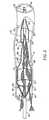
- Fig. 1illustrates the emboli capture device, generally as 10, used in conjunction with a standard guidewire 20 having a distal end 21 and a proximal end 22.
- the guidewire 20may be a standard, widely used guidewire presently in use having an outer diameter of approximately 0.356 mm (0.014 inch).
- the emboli capture deviceincludes components within the dotted circle 99 of Fig. 1 that are shown in detail in subsequent drawings.
- a mounting region 30Near the distal end 21 of guidewire 20 is a mounting region 30 which is shown in greater detail in the other drawings.
- the circle shown in dotted line 99 of Fig. 1identifies the area of guidewire 20 which carries the expandable and retractable components of the emboli capture device of the present invention.
- the distal end of the guidewire 21is inserted through an easily accessible artery as is known in the art and the distal end of the guidewire is moved into position downstream or distally of where the angioplasty or other intravascular procedure is to be performed.
- the present inventionprovides a low profile emboli capture device which has an overall outer diameter of approximately 0.508 mm (0.020 inch) when used with the standard guidewire presently in use having a diameter of 0.356 mm (0.014 inch) so that it may be utilized in arteries having inner diameters as small as approximately 1 mm. Assuming that future standard guidewires have diameters less than 0.356 mm (0.014 inch), the insertion diameter of the present invention would be reduced accordingly.
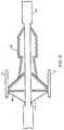
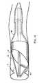
- Fig. 2illustrates a self-expanding stent 40 and filter means 60 in their expanded position wherein the stent 40 has expanded and pushed filter means into a sealing contact with arterial wall 9.
- the distal end of the guidewire 21carries a marker 25 to position the stent 40 and filter 60 downstream or distally from that portion of the artery where the angioplasty or other intravascular procedure is being performed.
- the stent 40is the preferred form of expansion means and is preferably a self-expanding stent having a plurality of nitinol arms.
- the illustrated embodimenthas four arms, three of which are visible in Fig. 2 as 41, 42 and 43.
- the nitinol armshave a shape memory and are formed so that the arms tend to move to their expanded position as illustrated in Fig. 2.
- the resilient arms 41, 42 and 43may be compressed against guidewire 20 by exerting an inwardly directed radial force against them compressing them against guidewire 20.
- the phrase "expansion means"is, used in its broadest sense as any device used to cause filter means 60 to expand.
- expansion meansare discussed below.
- the preferred expansion meansis a "self-expanding stent," that phrase being used herein and in the claims in its broadest sense as a plurality of arms which have a shape memory expanded position wherein they are capable of contacting arterial walls and supporting a filter such as filter 60 and which may be compressed or folded against the guidewire 20 by radial forces applied against the arms.
- Filter means 60may be of a variety of shapes but the preferred shape is a dual chamber, elongated shape illustrated in Fig. 2.
- Filter means 60includes a circular, cylindrical intake 61 of sufficiently large diameter to contact and seal against the arterial wall 9.
- a plurality of tethers or shrouds 64connects the intake 61 to guidewire 20. A more detailed description of the tethers is provided below.
- the intake 61is connected to a first emboli collection chamber 65.
- First chamber 65includes a tapered region 68, and an elongated region 66 having a reduced cross-sectional area at its distal end forming a throat 67.
- a second emboli collection chamber 70is connected integrally to first chamber 65 by having an inlet 71 of a larger diameter than the throat section 67 of first chamber 65.
- the second chamber 70has a cylindrical region 75 and a tapered region 73 near its distal end 72 and contacts guidewire 20 at its distal end 72.
- the purpose of the second emboli collection chamber 70is to collect the hardest and most dense particles of plaque captured by the filter means 60.
- the first, upstream chamber 65is designed to capture the softer pieces of plaque. If the first chamber 65 becomes partially filled with plaque during the surgical procedure, its contents may be suctioned out by the catheter used during the surgical procedure.
- the first chamber 65is designed with a tapered section 68 through which the contained plaque moves toward the smaller cylindrically shaped section chamber 66.
- the tapered region 68allows blood in the artery 9 to flow freely therethrough, as shown by arrows 8, and around the reduced section 66 of chamber 65 even if the reduced section 66 is completely filled with emboli.
- the design of elongated and dual chambered filter means 60is to provide ample storage volume for emboli that may be dislodged during the surgical procedure while simultaneously allowing a relatively large cross-sectional area of the filter to allow arterial blood to flow through the filter, as shown by arrows 8, even though the filter contains a significant amount of captured emboli in chambers 65 and 70.
- the secondary chamber 70 and the downstream section 66 of chamber 65are sized so that, when fully expanded, they occupy less cross-sectional area than the cross-sectional area of artery 9, so that blood flow through artery 9 is not restricted.
- Filter means 60is preferably formed from polymer Coretharie in a solvent solution to form a fused; multi-layered and thin walled mesh (i.e., 0.076 mm (0.003 inch)) having pores or orifices of predetermined size to trap emboli, as small as 20 microns if desired.
- the preferred pore or orifice sizewill trap emboli of 50 microns or larger.
- the filter meshis produced with a 30 nozzle spinneret which extrudes Corethane fibers into filaments of about 10 to 30 microns diameter over a mandrel having the shape of the desired fitter. The angle of winding the filaments varies from about 30° to 50° relative to the horizontal axis of rotation of the mandrel.
- the spinnaretreciprocates back and forth between the ends of the mandrel.
- the preferred filter mesh shown in Fig. 27has been achieved with 20 passes (one pass including one forward motion and one backward motion of the spinnaret) at 45° and having a resultant wall thickness of 0.064 mm (0.0025 inch), and orifices or pores small enough to trap 100 micron and larger emboli or other debris.
- Suitable filter materialmay be achieved using between 5 and 50 passes at between a 30° and 55° angle from the horizontal.
- the multiple layers in the filter meshfuse together by solvent joining. Evaporation of solvent is caused by IR (infrared) heaters. Background information on spinning vascular grafts is described in U.S. patent Nos. 4,475,972 and 5,163,951 .
- FIG. 28A significant alternate embodiment of the filter mesh is shown schematically in Fig. 28, wherein the cross sectional profile of each filament has been flattened by "fiber slumping" which includes application of heat to the extruded filaments.
- the resulting "fiber slumped” filamentshave cross-sections wherein the width "W” is preferably between 1.5 and 3 times the height "h” of the filament, however the ratio of width to height is not limited to that range.
- the resultant effectis a multi-layered, fused mesh with reduced wall thickness for a given number of passes. For example, applying "fiber slumping" to the mesh shown in Fig. 27 would reduce the wall thickness from 0.064 mm (0.0025 inch) to about 0.0254 mm (0.001 inch).
- the meshmay be coated for several purposes.
- the meshcan be coated with a non-thrombogenic coating such as heparin to prevent new clot formation on the mesh surface.
- a hydrogel coatingcan be applied to the mesh surface. This coating is intended to swell upon contacting aqueous media such as blood. The swollen gel on the mesh reduces the effective size of the pores or orifices provided by the mesh. That feature in turn reduces the number of layers of filter material to achieve the proper size of the orifice or holes. The use of fewer layers of polyurethane material achieves a thinner mesh, keeping the overall profile of the device to a minimum.
- a further advantage of the hydrogel coatingis that the sticky nature of the coating at the edge of the holes tends to help capture emboli particles.
- Figs. 3 through 9represent schematically how the invention is "packaged” and deployed. These drawings are not to scale and show in exaggerated fashion various aspects of the invention and are presented solely for purposes of illustrating the invention.
- Figs. 3-5show how the self-expanding stent and filter means of the present invention are "packaged” relative to the guidewire 20 to achieve the smallest possible profile.
- Figs. 6-9show how the sleeve is moved to allow the stent/filter combination to expand and deploy.
- Fig. 3shows that portion of the guidewire 20 within the circle 99 of Fig. 1.
- Guidewire 20has a stent/filter mounting region 30 which is preferably machined into guidewire 20.
- guidewire 20has an outer diameter d 1 of 0.356 mm (0.014 inches) and the stent mounting region 30 has an outer diameter d2 of 0.152 mm (0.006 inches).
- L 1 of mounting region 30is approximately 17 mm. The length of L 1 may vary according to the particular filter and particular stent being used:
- Mounting region 30 as illustrated in Fig. 3includes a vertical proximal wall 31 and a vertical distal wall 32.
- end walls 31 and 32 of mounting region 30could be other shapes without departing from the scope of the invention.
- the inventionalternately could use a tapered guidewire with a reduced cross-sectional region having only a proximal end wall and no distal end wall, as described below.
- Fig. 4shows schematically how the self-expanding stent 40 and filter means 60 are folded against guidewire 20 within mounting region 30. It is significant to note that the overall diameter d 3 of the retracted stent 40 and folded filter 60 is approximately the same as the outer diameter d 1 of guidewire 20, i.e., 0.356 mm (0.014 inches). The phrase "approximately” means that the diameters d 1 and d 3 are sufficiently close so that the overall performance of the device in being inserted, deployed and retrieved is not compromised. Applicants believe the diameters d 1 and d 3 should be within 20% of each other. It is to be understood that the self-expanding stent 40 must be compressed and held against the mounting region 30 to be kept in its retracted position illustrated in Fig. 4.
- FIG. 5illustrates how the retracted stent 40 and folded filter means 60 are held against the mounting region 30 of guidewire 20.
- a sleeve means 80is provided having an inner first layer 81 that extends over mounting region 30 from a position proximal of end wall 31 to a position distally of end wall 32.
- Sleeve means 80has a second outer layer 82 that extends over the first layer 81 from a position 85 where the sleeve is infolded; the infolding is located distally of distal wall 32 of mounting region 30 to a position proximally of proximal end wall 31 of mounting region 30.
- the double wall sleeve means 80allows for movement of the sleeve means 80 from its first position illustrated in Fig.
- the double layered sleeve means 80allows for movement of the sleeve means to its second position without requiring frictional motion of the sleeve means 80 against the folded filter material of filter means 60.
- the overall outer diameter d 4 of the assembled deviceis 0.508 mm (0.020 inch), assuming sleeve layers 81 and 82 are each 0.076 mm (0.003 inch) thickness.
- the outer diameter d 4 shown in Fig. 5is the "effective insertion diameter" of the device, since it is inserted and deployed without a catheter.
- a sleeve means 80 having only a single layer extending across mounting region 30It is also within the scope of this invention to utilize a sleeve means 80 having only a single layer extending across mounting region 30.
- the disadvantage of that embodiment of the inventionis the frictional motion of the sleeve means 80 against the material of filter means 60 as the sleeve is moved to a position where the stent 40 is free to expand. Such frictional motion against the filter 60 could possibly adversely affect the opening and performance of filter means 60.
- Fig. 6illustrates that the second layer of sleeve means 80 has been pulled in a direction proximally relative to mounting region 30.
- Fig. 7illustrates schematically that the sleeve means 80 has been moved slightly more than half way across mounting region 30.
- Fig. 8shows sleeve means 80 moved to a position where it no longer covers any of mounting region 30 and the self-expanding stent 40 and filter means 60 are beginning to expand.
- Fig. 9illustrates schematically that the stent 40 and filter means 60 have expanded fully and the intake of the filter means 60 has contacted the arterial wall.
- Sleeve means 80extends lengthwise along guidewire 20 from its double infolded distal end 85 to the proximal end 22 of guidewire 20.
- a handle 90(Fig. 1) is carried at the proximal end 22 of guidewire 20, and is bonded to the proximal end of sleeve 80. After the self-expanding stent 40 and filter 60 are deployed in an artery, handle 90 is used (as described below) to remove the sleeve 80 from guidewire 20.
- Fig. 9also illustrates that sleeve means 80 has been removed and guidewire 20 is now free to support and guide a catheter (not shown) into place in the artery.
- sleeve means 80in compressing the stent 40 and filter 60 in mounting region 30, as shown in Fig. 5, maintains the structural stability and "pushability" of guidewire 20.
- sleeve means 80may be a solid, imperforate sleeve with a distal end 87.
- a second embodiment sleeve 180has a woven, distal end section 187 that covers the mounting region 30 of guidewire 20.
- Sleeve 180is shown in Fig. 11. with a plurality of orifices 195 formed near its distal end section 187. Orifices 195 may be used to introduce lubricant or medicine into the artery to facilitate insertion of the device or placement of medicine within the artery.
- sleeve means 80is that, in its preferred form, it is "splittable" to allow a rapid removal of the sleeve 80 from guidewire 20. Ordinarily, sleeve means 80 would have to be slid completely off the proximal end of guidewire 20. As shown in Fig. 12, the sleeve means 80 is bonded to handle 190 and may be split by simply opening handle 190. Openable handle 190 has two parts 191 and 192 that are pivotally connected at hinge 193. Sleeve means 80 is bonded to the two parts 191 and 192. Opening the handle splits sleeve means 80 so that it may be easily separated from guidewire 20.
- Sleeve means 80has a longitudinally extending line of weakening, so that as it is withdrawn from the patient's body, it is simply split away from guidewire 20 rather than having to be slid off the proximal end of guidewire 20.
- This splittable sleeve featureallows the use of a shorter guidewire, decreases the time required to perform the procedure, and in many cases, requires one less person in the operating room to perform the procedure.
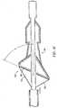
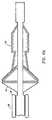
- FIG. 13 and 14Another significant variation of the present invention is the use of an alternate self-expanding stent 140 and filter means 160 to achieve an angular placement in the artery as shown in Figs. 13 and 14.
- the purpose of this designis to achieve a more complete seal of the filter means 160 against the walls of the artery.
- the angular orientationis achieved by providing stent 140 with arms 141,142 of different lengths and filter means 160 with an elliptical opening 161.
- the angular orientation A between the longitudinal axis of the guidewire 20 and the filter inlet 161is between 30° and 90°.
- the deviceis the same as the first embodiment shown in Figs. 2-9.
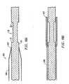
- FIG. 15Another embodiment of the invention utilizes a filter means 260 (Fig. 15) which is a plastic tube 261 wherein a plurality of laser cut perforations 295 is formed. As shown in Fig. 15, each perforation is generally H-shaped. Alternately, as shown in Fig. 16, the perforations 395 could be circular with sufficiently small diameters to allow blood to pass through, but not emboli.
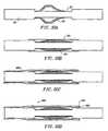
- Figs. 17A through Dshow how the catheter 98 utilized to perform the angioplasty or other intravascular procedure is used to retract and retrieve the deployed or expanded stent 40 and filter 60.
- the catheteris moved distally as shown in Figs. 17A and 17B and begins to collapse the stent 40 and filter 60.
- Fig. 17Cshows a further collapse or retraction of stent 40 and filter 60.
- Fig. 17Dshows the catheter advanced to a position where the stent 40 is fully collapsed and the extreme distal end 97 of the catheter 98 is approximately at the midpoint of the mounting region 30.
- the second chamber 65will contain emboli and the outer diameter of chamber 65 with emboli will typically be approximately the same or less than the outer diameter of catheter 98.
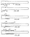
- Figs. 18-21illustrate alternate embodiments of sleeve means 80 and particularly the manner in which sleeve means 80 is applied to the guidewire.
- Figs. 18A and Billustrate a third embodiment of sleeve means 280 and illustrate how it is applied over the guidewire 20.
- Fig. 18Aillustrates that the distal end 287 of sleeve means 280 has been crumpled in order to make it significantly more flexible and of slightly smaller diameter than the main body 286 of sleeve 280. The clearance between the sleeve body 286 and guidewire 20 is exaggerated for illustrative purposes.
- Fig. 18Bshows that, as sleeve means 280 is moved distally, the larger and non-crumpled portion of the sleeve extends to the distal end of mounting region 30. In this position, the sleeve has an infolding 285 distally of mounting region 30 and is ready to be moved in the proximal direction to release the stent/filter assembly (not shown for clarity).
- Fig. 19illustrates a fourth embodiment of sleeve means 380 having body 386, wherein the distal end 387 carries a helical spring 388 to compress distal end 387 and the stent/filter assembly against guidewire 20.
- the embodiment shown in Fig. 19is not preferred, because of the friction between sleeve 380 and the stent/filter assembly as sleeve 380 is removed proximally.
- Figs. 20A through Dillustrate a fifth type of sleeve means 480 and its manner of application to the guidewire 20 and over the stent/filter assembly 101.
- Fig. 20Aillustrates the stent/filter assembly 101 in position on mounting region 30.
- Fig. 20Billustrates the placement of a first layer 481 of sleeve material that is drawn into position over mounting region 30 and which compresses the stent/filter assembly 101.
- Fig. 20Cillustrates that the main body portion 486 of sleeve means 480 is drawn over the length of the guidewire 20 and across mounting region 30. The distal ends of first section 481 and of body section 486 are joined by adhesive 489.
- the sleeve means 480is now in position with the double fold 485 at its distal end as described above.
- Figs. 21A through Iillustrate another sleeve means 580 and the manner in which it is applied to an alternate guidewire 120.
- alternate guidewire 120has its entire distal end 121 formed with a reduced diameter of, for example 0.203 mm (0.008 inches) while the main body 126 of guidewire has a diameter of 0.356 mm (0.014 inch).
- the design of the distal end 121 of guidewire 120, illustrated in Fig. 21A.allows the loading of the stent filter assembly 101 over the distal end 121 of guidewire 120.
- a sleeve retaining groove 125is formed in the surface of guidewire 120 near the proximal wall 131 of mounting region 130.
- the retaining groove 125has a gently sloping proximal surface 127 and a distal end wall 128, which is generally perpendicular to the surface of guidewire 120.
- the distal end 581 of sleeve means 580carries a spring loaded collar 582 which is intended to seat in the sleeve retaining groove 125.
- the sleeve means 580is moved distally with respect to guidewire 120, to achieve the double fold 585 discussed above, with spring loaded collar 582 anchored in the sleeve retaining groove 125.
- a sleeve spreader 586is inserted from the distal end of guidewire 120 and is slid underneath the distal end of sleeve means 580 and contacts the surface 127 of guidewire 120 adjacent the sleeve retaining groove 125.
- the sleeve spreader 586is a generally cylindrical, multi-sectional removable tool that is utilized to spread the distal end of sleeve means 580 and facilitate the insertion of the stent/filter assembly 101 over the distal end 121 of guidewire 120. As shown in Fig.
- the sleeve spreader 586has its distal end 587 expanded to stretch the distal end of sleeve means 580 and to allow the stent/filter assembly 101 to be slid underneath distal end 587.
- the stent/fitter assembly 101is moved proximally relative to guidewire 120 until it seats against wall 131 or until it is the proper clearance from wall 131, wherein the stent/filter assembly is compressed.
- the sleeve spreaderis then removed distally and the sleeve means 580 compresses the stent/filter assembly against the guidewire 120 as shown in Fig. 21 H. As illustrated best in Fig.
- a cylindrical ring 124 having an outer diameter of 0.356 mm (0.014 inch) or lessis slid onto the distal end 121 of guidewire 120.
- the distal end of ring 127is then welded or otherwise permanently attached to guidewire 120 as shown at 128 and the assembly is ready for use.
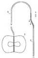
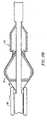
- FIG. 22illustrates an alternate form of tether or shroud 164 used to anchor filter means 60 to the guidewire.
- Fig. 22illustrates that the multiple tethers 164 are formed of a single strand of material 169 which is threaded around the periphery of circular intake 61 of filter means 60 and the single strand of material 169 is used to form tethers 164.
- Fig. 22shows approximately forty per cent of the circumference of intake 61 with the tethers and strand 169 applied, in the interest of clarity. In use, the full circumference carries strand 169, as well as tethers.
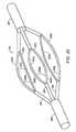
- Figs. 23 and 24illustrate an alternate form of self-expanding stent 240.
- Stent 240includes a cylindrical proximal sleeve 244, a cylindrical distal sleeve 245, and three separate arms 241, 242 and 243 extending between sleeves 244 and 245.
- Each of the stent arms 241-243has a longitudinal laser cut 241 a, 242a and 243a formed in the central portions, respectively. The primary purpose of the longitudinal cuts is to maximize the number of supporting arms for the intake of the filter means 60.
- a total of six arm segments 241b, 241c, 242b, 242c, 243b and 243care thereby formed, which provide a circular periphery which causes the filter means to contact and seal against the artery wall.
- An additional purpose for the use of the longitudinal cuts in only the central portion of the longitudinal length of stent means 240is to provide maximum self-expansion strength where the arms 241-243 bend relative to sleeves 244 and 245. Stent means 240 is rather small as far as stents go. Providing the maximum strength at the distal and proximal ends of the stent arms 241-243 assures that the stent means 240 will have the maximum ability to expand outwardly to contact the arterial wall.
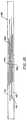
- Fig. 24illustrates in layout form the design of stent means 240 as illustrated in Fig. 23.
- Stent means 240includes longitudinal cuts or slots 241 a, 242a and 243a.
- Fig. 25illustrates another self-expanding stent 340, similar to stent 240, but wherein proximal end piece 344 and end piece 345 are each formed from three arcuate segments and welded together on weld lines 350.
- stent 340is identical to stent 240.
- Fig. 26is a plan view of the alternate stent 140 illustrated in Figs. 13 and 14 with an elliptical intake.
- the elliptical intake as illustrated in Fig. 14is formed by the use of longitudinal cuts 141 a, 142a and 143a that are spaced apart from each other along the longitudinal axis of stent 140.
- Fig. 29Ashows a helical expansion ring 440 that is connected to the inlet of the filter 460.
- Expansion ring 440has a proximal end 441 and distal end 442.
- Distal end 442is fixed to guidewire 20.
- the filter 560could have resilient, expansion material 540 embedded in its inlet as shown in Fig. 29B.
- Fig. 29Cillustrates yet another alternate filter means 660 having an inclined "sail” 640 at its inlet.
- the sail 640acts as an expansion mechanism to expand filter means 660 when exposed to arterial blood flow.
- Fig. 29Dillustrates another form of expansion means, wherein filter 760 has its inlet coated with a hydrogel coating 740 which swells upon contact with blood and acting to expand the inlet of filter 760.
- Fig. 30illustrates another embodiment of the invention wherein guidewire 820 has a tapered distal end 821.
- Mounting region 830is a recess in guidewire 820 having only one end wall, i.e., proximal end wall 831.
- Stent 840is attached to guidewire 820 by a weld 850 adjacent proximal end wall 831 or other permanent connection.
- This embodimenthas the disadvantage that stent 840 cannot "float" relative to guidewire 820.
- the alternate stents 40, 140, 240 and 340may either be allowed to "float” on guidewire 20 between end walls 31 and 32, as shown best in Figs. 8, 9 and 13, or it may be fixed to guidewire 20 at either its distal or proximal ends.
- the advantage of being able to "float”is that any inadvertent longitudinal motion or rotation of the guidewire is not immediately transmitted to the stent 40. This feature provides a level of "shock absorption" which minimizes adverse effects from unintended motion of guidewire 20.
- the stentis able to float by having a longitudinal length less than the longitudinal length of mounting region 30 between end walls 31 and 32, shown by clearance "x" in Figs. 8, 9 and 13. Clearance "x" is preferably between 0.254 and 3.175 mm (0.010 and 0.125 inch).
Landscapes
- Health & Medical Sciences (AREA)
- General Health & Medical Sciences (AREA)
- Veterinary Medicine (AREA)
- Transplantation (AREA)
- Engineering & Computer Science (AREA)
- Biomedical Technology (AREA)
- Heart & Thoracic Surgery (AREA)
- Vascular Medicine (AREA)
- Life Sciences & Earth Sciences (AREA)
- Animal Behavior & Ethology (AREA)
- Cardiology (AREA)
- Oral & Maxillofacial Surgery (AREA)
- Public Health (AREA)
- Surgical Instruments (AREA)
- Media Introduction/Drainage Providing Device (AREA)
- Steroid Compounds (AREA)
- User Interface Of Digital Computer (AREA)
- Transition And Organic Metals Composition Catalysts For Addition Polymerization (AREA)
- Prostheses (AREA)
- Glass Compositions (AREA)
- Electronic Switches (AREA)
- Ultra Sonic Daignosis Equipment (AREA)
Abstract
Description
- The present invention relates generally to an emboli capture device for use in conjunction with angioplasty and other intravascular surgeries. More particularly, the present invention provides a low profile emboli capture device (i.e. approximately 0.508 mm (0.020 inch) diameter or less in its retracted position) capable of being used in smaller diameter blood vessels than prior art emboli capture devices, as well as reducing the risk of dislodging plaque in larger vessels. The present invention provides an emboli capture device carried by a standard guidewire; a catheter is not required to insert and deploy the emboli capture device. The invention is capable of use in carotid angioplasty without occluding blood flow to the brain, and can be used in saphenous vein grafts, native coronary arteries and arteries as small as 1 mm. diameter.
- As angioplasty and other intravascular surgical procedures progress, it becomes increasingly important to be able to use an emboli capture device in smaller and smaller arteries, requiring the use of lower profile devices.
US-A-5, 910, 154 pertains to an apparatus for treating stenosed blood vessels including a filter disposed on an expandable frame and deployable by withdrawing a sheath.WO98/33443 - In accordance with the present invention, an emboli capture device as recited in the claims is provided which in its preferred form includes three main components that cooperate with a standard guidewire; a self-expanding stent (or other expansion means), a filter and a sleeve. The filter and self-expanding stent in the preferred embodiment are carried directly on a reduced cross-sectional mounting region of the guidewire so that those components of the device in their retracted form have essentially the same cross-sectional profile as the guidewire, itself. The present invention also provides a thin sleeve which holds the filter and self-expanding stent against the guidewire. The thin sleeve is then retracted proximally relative to the guidewire, allowing the filter and self-expanding stent (or other expansion means) of the present invention to expand. The same guidewire which is used to place the emboli capture device of the present invention is used to guide the surgical catheter into place for performing the angioplasty or other intravascular surgery. The catheter, itself, is utilized to retract and retrieve the emboli capture device at the conclusion of the procedure.
- A primary object of the invention is to provide a low profile emboli capture device.
- Another major object of the invention is to provide an emboli capture device capable of use in carotid and saphenous vein graft angioplasty and stenting without occlusion of blood flow.
- A further object of the invention is to provide an emboli capture device which, in its retracted position, has a filter and self-expanding stent (or other expansion means) carried in a reduced cross-sectional region of the guidewire so that the filter and self-expanding stent (or other expansion means) combination in its retracted position have a cross-sectional area essentially the same as the cross-sectional area of the guidewire.
- A further object of the invention is to provide a low profile emboli capture device carried near the distal end of a standard guidewire and having a thin sleeve holding the expandable stent (or other expansion means) and filter in a retracted position on the guidewire and wherein the sleeve may be moved to a second position allowing the device to expand outwardly and contact the arterial wall.
- Yet another object of the invention is to provide an emboli capture device having an outer diameter of approximately 0.508 mm (0.020 inch) when used with a currently standard guidewire of 0.356 mm (0.014 inch) and wherein that dimension represents the effective insertion diameter of the device, since insertion of the device may be done without using a catheter.
- A further object of the invention is to provide an emboli capture device having a low profile and which is carried at the distal end of a standard diameter guidewire, wherein the same guidewire is utilized to guide a surgical catheter into position for an angioplasty or other intravascular procedure, and wherein the catheter utilized to perform the surgery is also utilized to retract and retrieve the emboli capture device at the conclusion of the surgical procedure.
- Other objects and advantages of the invention will become apparent from the following description and the drawings wherein:
- Fig. 1 is a schematic representation of the emboli capture device of the present invention with an expandable stent and filter carried near the distal end of the guidewire in the region circled with a dotted line;
- Fig. 2 is a schematic representation partially in section and partially broken away showing the emboli capture device of the present invention in its expanded position inside an artery;
- Figs. 3, 4 and 5 show schematically how the emboli capture device of the present invention is packaged on a standard guidewire and, in particular,
- Fig. 3 illustrates a section of a standard guidewire having a mounting region of reduced cross-sectional area;
- Fig. 4 is a schematic representation of that portion of the guidewire shown in Fig. 3 wherein the expandable stent and filter components of the present invention are shown schematically in their folded or retracted position within the reduced cross-sectional mounting region of the guidewire;
- Fig. 5 is a schematic representation showing the movable sleeve in position over the retracted and folded expandable stent and filter;
- Fig. 6 is a schematic illustration showing the sleeve as it is being moved proximally relative to the guidewire and the retracted stent/filter combination;
- Fig. 7 shows the sleeve of Fig. 6 as it is moved further in the proximal direction relative to the guidewire and the folded stent/filter;
- Fig. 8 illustrates the sleeve moved completely off the retracted stent/filter and wherein the stent/filter combination is beginning to expand;
- Fig. 9 is a schematic representation showing the emboli capture device in its fully expanded position;
- Fig. 10 is a schematic representation showing a sleeve having a cylindrical imperforated shape connected to a handle for moving the sleeve relative to the guidewire;
- Fig. 11 is a schematic representation of an alternate sleeve having an open woven distal portion and having a plurality of orifices formed in a region near its distal portion for introducing lubricants or medicine;
- Figs. 12A and 12B are cross-sectional views of a handle which may be used in the present invention to move the sleeve relative to the guidewire as well as to split the sleeve to allow rapid separation of the sleeve from the guidewire;
- Fig. 13 is a side elevational view, partially in section, showing an alternate form of the invention having an elliptical opening formed in the filter and in the stent used to deploy the filter;
- Fig. 14 is a side elevational view of the stent and filter combination of Fig. 13 having an elliptical opening and showing the elliptical opening in contact with the arterial wall;
- Fig. 15 is a schematic representation of an alternate filter used in the invention wherein the filter is a plastic material with generally H-shaped perforations formed by laser cutting;
- Fig. 16 is a schematic representation of an alternate filter used in the invention wherein the filter is a plastic material with circular shaped perforations formed by laser cutting;
- Figs. 17A through D are schematic representations showing how the emboli capture device shown in Fig. 2 is retracted and retrieved at the end of the angioplasty or other intravascular procedure by using a catheter;
- Figs. 18A and 18B are schematic representations showing the application of a third form of sleeve;
- Fig. 19 is a schematic representation showing the application of a fourth form of sleeve onto the guidewire;
- Figs. 20A through D are schematic representations of a fifth form of sleeve means and how it is applied over the guidewire and the stent/filter assembly;
- Figs. 21 A through I are schematic illustrations showing a sixth form of the sleeve and how it is applied to a modified guidewire, and illustrating how the stent/filter assembly may be installed from the distal end of the guidewire;
- Fig. 22 is a perspective view illustrating the preferred manner of forming the tethers for the intake of the filter means;
- Fig. 23 is a perspective view of an alternate form of the stent;
- Fig. 24 is a plan view of the stent illustrated in Fig. 23 shown in layout form;
- Fig. 25 is a perspective view of another self-expanding stent usable in the invention;
- Fig. 26 is a plan view of the stent having an elliptical opening illustrated in Figs. 13 and 14, wherein the stent is shown in its layout form;
- Fig. 27 is a microscopic photograph of the multi-layer mesh filter material used in the preferred embodiment of the invention, shown at 45 times magnification;
- Fig. 28 is a schematic illustration of an alternate multi-layer mesh filter material wherein each filter has been formed with a flattened or slumped cross-section;
- Figs. 29A through D are schematic illustrations of alternate expansion means capable of use in the present invention; and
- Fig. 30 illustrates an alternate form of the invention wherein the mounting region is a recess formed with only a proximal end wall and wherein the guidewire has a tapered distal end.
- Fig. 1 illustrates the emboli capture device, generally as 10, used in conjunction with a
standard guidewire 20 having adistal end 21 and aproximal end 22. Theguidewire 20 may be a standard, widely used guidewire presently in use having an outer diameter of approximately 0.356 mm (0.014 inch). The emboli capture device includes components within thedotted circle 99 of Fig. 1 that are shown in detail in subsequent drawings. - Near the
distal end 21 ofguidewire 20 is amounting region 30 which is shown in greater detail in the other drawings. The circle shown indotted line 99 of Fig. 1 identifies the area ofguidewire 20 which carries the expandable and retractable components of the emboli capture device of the present invention. In practice, the distal end of theguidewire 21 is inserted through an easily accessible artery as is known in the art and the distal end of the guidewire is moved into position downstream or distally of where the angioplasty or other intravascular procedure is to be performed. As is described in greater detail below, the present invention provides a low profile emboli capture device which has an overall outer diameter of approximately 0.508 mm (0.020 inch) when used with the standard guidewire presently in use having a diameter of 0.356 mm (0.014 inch) so that it may be utilized in arteries having inner diameters as small as approximately 1 mm. Assuming that future standard guidewires have diameters less than 0.356 mm (0.014 inch), the insertion diameter of the present invention would be reduced accordingly. - Fig. 2 illustrates a self-expanding
stent 40 and filter means 60 in their expanded position wherein thestent 40 has expanded and pushed filter means into a sealing contact witharterial wall 9. The distal end of the guidewire 21 carries amarker 25 to position thestent 40 andfilter 60 downstream or distally from that portion of the artery where the angioplasty or other intravascular procedure is being performed. - The
stent 40 is the preferred form of expansion means and is preferably a self-expanding stent having a plurality of nitinol arms. The illustrated embodiment has four arms, three of which are visible in Fig. 2 as 41, 42 and 43. The nitinol arms have a shape memory and are formed so that the arms tend to move to their expanded position as illustrated in Fig. 2. A more detailed description of thestent 40 is provided below. Theresilient arms guidewire 20 by exerting an inwardly directed radial force against them compressing them againstguidewire 20. As used herein and in the claims, the phrase "expansion means" is, used in its broadest sense as any device used to cause filter means 60 to expand. Some alternate "expansion means" are discussed below. The preferred expansion means is a "self-expanding stent," that phrase being used herein and in the claims in its broadest sense as a plurality of arms which have a shape memory expanded position
wherein they are capable of contacting arterial walls and supporting a filter such asfilter 60 and which may be compressed or folded against theguidewire 20 by radial forces applied against the arms. - Filter means 60 may be of a variety of shapes but the preferred shape is a dual chamber, elongated shape illustrated in Fig. 2. Filter means 60 includes a circular,
cylindrical intake 61 of sufficiently large diameter to contact and seal against thearterial wall 9. A plurality of tethers orshrouds 64 connects theintake 61 to guidewire 20. A more detailed description of the tethers is provided below. Theintake 61 is connected to a firstemboli collection chamber 65.First chamber 65 includes a taperedregion 68, and anelongated region 66 having a reduced cross-sectional area at its distal end forming athroat 67. A secondemboli collection chamber 70 is connected integrally tofirst chamber 65 by having an inlet 71 of a larger diameter than thethroat section 67 offirst chamber 65. Thesecond chamber 70 has acylindrical region 75 and a taperedregion 73 near itsdistal end 72 and contacts guidewire 20 at itsdistal end 72. - The purpose of the second
emboli collection chamber 70 is to collect the hardest and most dense particles of plaque captured by the filter means 60. The first,upstream chamber 65 is designed to capture the softer pieces of plaque. If thefirst chamber 65 becomes partially filled with plaque during the surgical procedure, its contents may be suctioned out by the catheter used during the surgical procedure. - The
first chamber 65 is designed with a taperedsection 68 through which the contained plaque moves toward the smaller cylindrically shapedsection chamber 66. The taperedregion 68 allows blood in theartery 9 to flow freely therethrough, as shown byarrows 8, and around the reducedsection 66 ofchamber 65 even if the reducedsection 66 is completely filled with emboli. The design of elongated and dual chambered filter means 60 is to provide ample storage volume for emboli that may be dislodged during the surgical procedure while simultaneously allowing a relatively large cross-sectional area of the filter to allow arterial blood to flow through the filter, as shown byarrows 8, even though the filter contains a significant amount of captured emboli inchambers secondary chamber 70 and thedownstream section 66 ofchamber 65 are sized so that, when fully expanded, they occupy less cross-sectional area than the cross-sectional area ofartery 9, so that blood flow throughartery 9 is not restricted. - Filter means 60 is preferably formed from polymer Coretharie in a solvent solution to form a fused; multi-layered and thin walled mesh (i.e., 0.076 mm (0.003 inch)) having pores or orifices of predetermined size to trap emboli, as small as 20 microns if desired. The preferred pore or orifice size will trap emboli of 50 microns or larger. The filter mesh is produced with a 30 nozzle spinneret which extrudes Corethane fibers into filaments of about 10 to 30 microns diameter over a mandrel having the shape of the desired fitter. The angle of winding the filaments varies from about 30° to 50° relative to the horizontal axis of rotation of the mandrel. The spinnaret reciprocates back and forth between the ends of the mandrel. The preferred filter mesh shown in Fig. 27 has been achieved with 20 passes (one pass including one forward motion and one backward motion of the spinnaret) at 45° and having a resultant wall thickness of 0.064 mm (0.0025 inch), and orifices or pores small enough to trap 100 micron and larger emboli or other debris. Suitable filter material may be achieved using between 5 and 50 passes at between a 30° and 55° angle from the horizontal. The multiple layers in the filter mesh fuse together by solvent joining. Evaporation of solvent is caused by IR (infrared) heaters. Background information on spinning vascular grafts is described in
U.S. patent Nos. 4,475,972 and5,163,951 . - A significant alternate embodiment of the filter mesh is shown schematically in Fig. 28, wherein the cross sectional profile of each filament has been flattened by "fiber slumping" which includes application of heat to the extruded filaments. The resulting "fiber slumped" filaments have cross-sections wherein the width "W" is preferably between 1.5 and 3 times the height "h" of the filament, however the ratio of width to height is not limited to that range. The resultant effect is a multi-layered, fused mesh with reduced wall thickness for a given number of passes. For example, applying "fiber slumping" to the mesh shown in Fig. 27 would reduce the wall thickness from 0.064 mm (0.0025 inch) to about 0.0254 mm (0.001 inch).
- According to the present invention, the mesh may be coated for several purposes. First, the mesh can be coated with a non-thrombogenic coating such as heparin to prevent new clot formation on the mesh surface. Secondly, a hydrogel coating can be applied to the mesh surface. This coating is intended to swell upon contacting aqueous media such as blood. The swollen gel on the mesh reduces the effective size of the pores or orifices provided by the mesh. That feature in turn reduces the number of layers of filter material to achieve the proper size of the orifice or holes. The use of fewer layers of polyurethane material achieves a thinner mesh, keeping the overall profile of the device to a minimum. A further advantage of the hydrogel coating is that the sticky nature of the coating at the edge of the holes tends to help capture emboli particles.
- Figs. 3 through 9 represent schematically how the invention is "packaged" and deployed. These drawings are not to scale and show in exaggerated fashion various aspects of the invention and are presented solely for purposes of illustrating the invention. Figs. 3-5 show how the self-expanding stent and filter means of the present invention are "packaged" relative to the
guidewire 20 to achieve the smallest possible profile. Figs. 6-9 show how the sleeve is moved to allow the stent/filter combination to expand and deploy. - Fig. 3 shows that portion of the
guidewire 20 within thecircle 99 of Fig. 1.Guidewire 20 has a stent/filter mounting region 30 which is preferably machined intoguidewire 20. In the preferred form of the invention, guidewire 20 has an outer diameter d1 of 0.356 mm (0.014 inches) and thestent mounting region 30 has an outer diameter d2 of 0.152 mm (0.006 inches). In the preferred form of the invention, L1 of mountingregion 30 is approximately 17 mm. The length of L1 may vary according to the particular filter and particular stent being used: Mountingregion 30 as illustrated in Fig. 3 includes a verticalproximal wall 31 and a verticaldistal wall 32. Theend walls region 30 could be other shapes without departing from the scope of the invention. The invention alternately could use a tapered guidewire with a reduced cross-sectional region having only a proximal end wall and no distal end wall, as described below. - Fig. 4 shows schematically how the self-expanding
stent 40 and filter means 60 are folded againstguidewire 20 within mountingregion 30. It is significant to note that the overall diameter d3 of the retractedstent 40 and foldedfilter 60 is approximately the same as the outer diameter d1 ofguidewire 20, i.e., 0.356 mm (0.014 inches). The phrase "approximately" means that the diameters d1 and d3 are sufficiently close so that the overall performance of the device in being inserted, deployed and retrieved is not compromised. Applicants believe the diameters d1 and d3 should be within 20% of each other. It is to be understood that the self-expandingstent 40 must be compressed and held against the mountingregion 30 to be kept in its retracted position illustrated in Fig. 4. - Fig. 5 illustrates how the retracted
stent 40 and folded filter means 60 are held against the mountingregion 30 ofguidewire 20. A sleeve means 80 is provided having an innerfirst layer 81 that extends over mountingregion 30 from a position proximal ofend wall 31 to a position distally ofend wall 32. Sleeve means 80 has a secondouter layer 82 that extends over thefirst layer 81 from aposition 85 where the sleeve is infolded; the infolding is located distally ofdistal wall 32 of mountingregion 30 to a position proximally ofproximal end wall 31 of mountingregion 30. The double wall sleeve means 80 allows for movement of the sleeve means 80 from its first position illustrated in Fig. 5 to its second position illustrated in Fig. 8 where it no longer holds the self-expanding stent and the self-expandingstent 40 and filter means 60 are free to expand. The double layered sleeve means 80 allows for movement of the sleeve means to its second position without requiring frictional motion of the sleeve means 80 against the folded filter material of filter means 60. As shown in Fig. 5, the overall outer diameter d4 of the assembled device is 0.508 mm (0.020 inch), assuming sleeve layers 81 and 82 are each 0.076 mm (0.003 inch) thickness. The outer diameter d4 shown in Fig. 5 is the "effective insertion diameter" of the device, since it is inserted and deployed without a catheter. It is also within the scope of this invention to utilize a sleeve means 80 having only a single layer extending across mountingregion 30. The disadvantage of that embodiment of the invention is the frictional motion of the sleeve means 80 against the material of filter means 60 as the sleeve is moved to a position where thestent 40 is free to expand. Such frictional motion against thefilter 60 could possibly adversely affect the opening and performance of filter means 60. - Fig. 6 illustrates that the second layer of sleeve means 80 has been pulled in a direction proximally relative to mounting
region 30. Fig. 7 illustrates schematically that the sleeve means 80 has been moved slightly more than half way across mountingregion 30. Fig. 8 shows sleeve means 80 moved to a position where it no longer covers any of mountingregion 30 and the self-expandingstent 40 and filter means 60 are beginning to expand. Fig. 9 illustrates schematically that thestent 40 and filter means 60 have expanded fully and the intake of the filter means 60 has contacted the arterial wall. - Sleeve means 80 extends lengthwise along
guidewire 20 from its double infoldeddistal end 85 to theproximal end 22 ofguidewire 20. A handle 90 (Fig. 1) is carried at theproximal end 22 ofguidewire 20, and is bonded to the proximal end ofsleeve 80. After the self-expandingstent 40 andfilter 60 are deployed in an artery, handle 90 is used (as described below) to remove thesleeve 80 fromguidewire 20. Fig. 9 also illustrates that sleeve means 80 has been removed and guidewire 20 is now free to support and guide a catheter (not shown) into place in the artery. - It is significant to note that the use of sleeve means 80 in compressing the
stent 40 andfilter 60 in mountingregion 30, as shown in Fig. 5, maintains the structural stability and "pushability" ofguidewire 20. Ordinarily, a guidewire that has a recess formed in it similar to mountingregion 30 but, without any material packaged in the recess, would lose much of its columnar compressive strength, or pushability, and become much more likely to bend at one of theend walls - As shown in Fig. 10, sleeve means 80 may be a solid, imperforate sleeve with a
distal end 87. Alternately, as shown in Fig. 11, asecond embodiment sleeve 180 has a woven,distal end section 187 that covers the mountingregion 30 ofguidewire 20.Sleeve 180 is shown in Fig. 11. with a plurality oforifices 195 formed near itsdistal end section 187.Orifices 195 may be used to introduce lubricant or medicine into the artery to facilitate insertion of the device or placement of medicine within the artery. - Another aspect of sleeve means 80 is that, in its preferred form, it is "splittable" to allow a rapid removal of the
sleeve 80 fromguidewire 20. Ordinarily, sleeve means 80 would have to be slid completely off the proximal end ofguidewire 20. As shown in Fig. 12, the sleeve means 80 is bonded to handle 190 and may be split by simply openinghandle 190. Openable handle 190 has twoparts hinge 193. Sleeve means 80 is bonded to the twoparts guidewire 20. Sleeve means 80 has a longitudinally extending line of weakening, so that as it is withdrawn from the patient's body, it is simply split away fromguidewire 20 rather than having to be slid off the proximal end ofguidewire 20. This splittable sleeve feature allows the use of a shorter guidewire, decreases the time required to perform the procedure, and in many cases, requires one less person in the operating room to perform the procedure. - Another significant variation of the present invention is the use of an alternate self-expanding
stent 140 and filter means 160 to achieve an angular placement in the artery as shown in Figs. 13 and 14. The purpose of this design is to achieve a more complete seal of the filter means 160 against the walls of the artery. The angular orientation is achieved by providingstent 140 with arms 141,142 of different lengths and filter means 160 with anelliptical opening 161. The angular orientation A between the longitudinal axis of theguidewire 20 and thefilter inlet 161 is between 30° and 90°. In all other significant respects, the device is the same as the first embodiment shown in Figs. 2-9. - Another embodiment of the invention utilizes a filter means 260 (Fig. 15) which is a
plastic tube 261 wherein a plurality of laser cutperforations 295 is formed. As shown in Fig. 15, each perforation is generally H-shaped. Alternately, as shown in Fig. 16, theperforations 395 could be circular with sufficiently small diameters to allow blood to pass through, but not emboli. - Figs. 17A through D show how the
catheter 98 utilized to perform the angioplasty or other intravascular procedure is used to retract and retrieve the deployed or expandedstent 40 andfilter 60. The catheter is moved distally as shown in Figs. 17A and 17B and begins to collapse thestent 40 andfilter 60. Fig. 17C shows a further collapse or retraction ofstent 40 andfilter 60. Fig. 17D shows the catheter advanced to a position where thestent 40 is fully collapsed and the extremedistal end 97 of thecatheter 98 is approximately at the midpoint of the mountingregion 30. Thesecond chamber 65 will contain emboli and the outer diameter ofchamber 65 with emboli will typically be approximately the same or less than the outer diameter ofcatheter 98. Once the catheter has reached the position shown in Fig. 17D, where thestent 40 is fully collapsed and retracted againstguidewire 20, the catheter and guidewire are slid as a unit outwardly from the artery and out of the patient's body. - Figs. 18-21 illustrate alternate embodiments of sleeve means 80 and particularly the manner in which sleeve means 80 is applied to the guidewire. Figs. 18A and B illustrate a third embodiment of sleeve means 280 and illustrate how it is applied over the
guidewire 20. Fig. 18A illustrates that thedistal end 287 of sleeve means 280 has been crumpled in order to make it significantly more flexible and of slightly smaller diameter than themain body 286 ofsleeve 280. The clearance between thesleeve body 286 and guidewire 20 is exaggerated for illustrative purposes. The extremedistal end 287 is threaded overguidewire 20 and is held in place proximally of mountingregion 30 onguidewire 20 by either an adhesive bond 289 (or by frictional engagement) with the surface ofguidewire 20. Fig. 18B shows that, as sleeve means 280 is moved distally, the larger and non-crumpled portion of the sleeve extends to the distal end of mountingregion 30. In this position, the sleeve has aninfolding 285 distally of mountingregion 30 and is ready to be moved in the proximal direction to release the stent/filter assembly (not shown for clarity). - Fig. 19 illustrates a fourth embodiment of sleeve means 380 having
body 386, wherein thedistal end 387 carries ahelical spring 388 to compressdistal end 387 and the stent/filter assembly againstguidewire 20. The embodiment shown in Fig. 19 is not preferred, because of the friction betweensleeve 380 and the stent/filter assembly assleeve 380 is removed proximally. - Figs. 20A through D illustrate a fifth type of sleeve means 480 and its manner of application to the
guidewire 20 and over the stent/filter assembly 101. Fig. 20A illustrates the stent/filter assembly 101 in position on mountingregion 30. Fig. 20B illustrates the placement of afirst layer 481 of sleeve material that is drawn into position over mountingregion 30 and which compresses the stent/filter assembly 101. Fig. 20C illustrates that themain body portion 486 of sleeve means 480 is drawn over the length of theguidewire 20 and across mountingregion 30. The distal ends offirst section 481 and ofbody section 486 are joined byadhesive 489. The sleeve means 480 is now in position with thedouble fold 485 at its distal end as described above. - Figs. 21A through I illustrate another sleeve means 580 and the manner in which it is applied to an alternate guidewire 120. As shown in Fig. 21A, alternate guidewire 120 has its entire
distal end 121 formed with a reduced diameter of, for example 0.203 mm (0.008 inches) while the main body 126 of guidewire has a diameter of 0.356 mm (0.014 inch). The design of thedistal end 121 of guidewire 120, illustrated in Fig. 21A. allows the loading of thestent filter assembly 101 over thedistal end 121 of guidewire 120. Asleeve retaining groove 125 is formed in the surface of guidewire 120 near theproximal wall 131 of mounting region 130. The retaininggroove 125 has a gently slopingproximal surface 127 and adistal end wall 128, which is generally perpendicular to the surface of guidewire 120. As illustrated in Fig. 21 B, thedistal end 581 of sleeve means 580 carries a spring loadedcollar 582 which is intended to seat in thesleeve retaining groove 125. As shown in Figs. 21C and D, the sleeve means 580 is moved distally with respect to guidewire 120, to achieve thedouble fold 585 discussed above, with spring loadedcollar 582 anchored in thesleeve retaining groove 125. - As shown best in Fig. 21 E, a
sleeve spreader 586 is inserted from the distal end of guidewire 120 and is slid underneath the distal end of sleeve means 580 and contacts thesurface 127 of guidewire 120 adjacent thesleeve retaining groove 125. Thesleeve spreader 586 is a generally cylindrical, multi-sectional removable tool that is utilized to spread the distal end of sleeve means 580 and facilitate the insertion of the stent/filter assembly 101 over thedistal end 121 of guidewire 120. As shown in Fig. 21 G, thesleeve spreader 586 has itsdistal end 587 expanded to stretch the distal end of sleeve means 580 and to allow the stent/filter assembly 101 to be slid underneathdistal end 587. The stent/fitter assembly 101 is moved proximally relative to guidewire 120 until it seats againstwall 131 or until it is the proper clearance fromwall 131, wherein the stent/filter assembly is compressed. The sleeve spreader is then removed distally and the sleeve means 580 compresses the stent/filter assembly against the guidewire 120 as shown in Fig. 21 H. As illustrated best in Fig. 21I, acylindrical ring 124 having an outer diameter of 0.356 mm (0.014 inch) or less is slid onto thedistal end 121 of guidewire 120. The distal end ofring 127 is then welded or otherwise permanently attached to guidewire 120 as shown at 128 and the assembly is ready for use. - Another aspect of the invention is illustrated in Fig. 22 illustrating an alternate form of tether or
shroud 164 used to anchor filter means 60 to the guidewire. Fig. 22 illustrates that themultiple tethers 164 are formed of a single strand ofmaterial 169 which is threaded around the periphery ofcircular intake 61 of filter means 60 and the single strand ofmaterial 169 is used to form tethers 164. Fig. 22 shows approximately forty per cent of the circumference ofintake 61 with the tethers and strand 169 applied, in the interest of clarity. In use, the full circumference carriesstrand 169, as well as tethers. - Figs. 23 and 24 illustrate an alternate form of self-expanding
stent 240.Stent 240 includes a cylindricalproximal sleeve 244, a cylindricaldistal sleeve 245, and threeseparate arms sleeves arm segments sleeves - Fig. 24 illustrates in layout form the design of stent means 240 as illustrated in Fig. 23. Stent means 240 includes longitudinal cuts or
slots - Fig. 25 illustrates another self-expanding
stent 340, similar tostent 240, but whereinproximal end piece 344 andend piece 345 are each formed from three arcuate segments and welded together on weld lines 350. In all other respects,stent 340 is identical tostent 240. - Fig. 26 is a plan view of the
alternate stent 140 illustrated in Figs. 13 and 14 with an elliptical intake. The elliptical intake as illustrated in Fig. 14 is formed by the use oflongitudinal cuts stent 140. - It is to be understood that various "expansion means" could be used in addition to the self-expanding stents described above. For example, Fig. 29A shows a helical expansion ring 440 that is connected to the inlet of the
filter 460. Expansion ring 440 has aproximal end 441 anddistal end 442.Distal end 442 is fixed toguidewire 20. Alternately, thefilter 560 could have resilient,expansion material 540 embedded in its inlet as shown in Fig. 29B. Fig. 29C illustrates yet another alternate filter means 660 having an inclined "sail" 640 at its inlet. Thesail 640 acts as an expansion mechanism to expand filter means 660 when exposed to arterial blood flow. Fig. 29D illustrates another form of expansion means, whereinfilter 760 has its inlet coated with ahydrogel coating 740 which swells upon contact with blood and acting to expand the inlet offilter 760. - Fig. 30 illustrates another embodiment of the invention wherein
guidewire 820 has a tapereddistal end 821. Mountingregion 830 is a recess inguidewire 820 having only one end wall, i.e.,proximal end wall 831.Stent 840 is attached to guidewire 820 by aweld 850 adjacentproximal end wall 831 or other permanent connection. This embodiment has the disadvantage thatstent 840 cannot "float" relative to guidewire 820. - As noted above, the
alternate stents guidewire 20 betweenend walls stent 40. This feature provides a level of "shock absorption" which minimizes adverse effects from unintended motion ofguidewire 20. The stent is able to float by having a longitudinal length less than the longitudinal length of mountingregion 30 betweenend walls - The foregoing description of the invention has been presented for purposes of illustration and description and is not intended to be exhaustive or to limit the invention to the precise form disclosed. Many modifications and variations are possible in light of the above teaching. The embodiments were chosen and described to best explain the principles of the invention and its practical application to thereby enable others skilled in the art to best use the invention in various embodiments and with various modifications suited to the particular use contemplated. The scope of the invention is to be defined by the following claims.
Claims (26)
- A low profile emboli capture device for use in angioplasty and other intravascular procedures comprising:a guidewire (20) having distal and proximal ends, said guidewire having a mounting region (30) near said distal end,a self-expanding stent (40; 140; 240; 340) carried on said guidewire at said mounting region, said self-expanding stent being movable between a retracted position and an expanded position,a filter (60; 160) connected to said self-expanding stent, said filter being movable between a retracted position and an expanded position, said filter being adapted to capture emboli in its expanded position, anda sleeve (80; 180; 280; 380; 480; 580) having a first position for holding said self-expanding stent and said filter against said mounting region of said guidewire, said sleeve being movable to a second position wherein said self-expanding stent and said filter are free to expand, said sleeve is slidable on said guidewire and removable from said guidewire,characterized in that
said mounting region of said guidewire has a cross-sectional area less than said guidewire; and said self-expanding stent and said filter in their retracted positions on said mounting region have a cross-sectional profile approximately the same as the cross-sectional profile of said guidewire. - The device of claim 1 wherein said guidewire (20) and said sleeve (80; 180; 280; 380; 480; 580) have cylindrical cross sections and the outer diameter of said sleeve in its first position wherein it extends over said self-expanding stent (40; 140; 240; 340) and said filter (60; 160) is equal to or less than 0.508 mm (0.020 inch).
- The device of claim 2 wherein said filter (60; 160) is elongated and has first and second chambers and a tapered throat region with a reduced cross section between said chambers.
- The device of claim 1 wherein said filter (60; 160) is a multi-layered mesh formed of spun, liquid polymer.
- The device of claim 4 further comprising a non-thrombogenic coating applied to said filter (60; 160).
- The device of claim 4 further comprising a hydrogel coating applied to said filter (60; 160), said hydrogel coating expanding upon contact with blood.
- The device of claim 4 wherein said multi-layered mesh comprises fiber slumped filaments each having a width that is greater than its height.
- The device of claim 1 wherein said filter (60; 160) comprises a plurality of perforations in a plastic tube.
- The device of claim 1 wherein said sleeve (80; 180; 280; 380; 480; 580) is slidable on said guidewire (20) and includes an inverted, double folded end portion (85) extending over said self-expanding stent (40; 140; 240; 340) and said filter (60; 160), so that as said sleeve is moved from said first position to said second position, it releases said self-expanding stent and said filter without frictional movement between said sleeve and said filter.
- The device of claim 1 wherein the emboli capture device has a profile sufficiently small that said device may be used with conventional guidewires and catheters commonly used in angioplasty and other intra-vascular procedures.
- The device of claim 1 wherein said self-expanding stent (40; 140; 240; 340) and said filter (60; 160) are moved from their expanded positions to their retracted positions by advancing said catheter in a distal direction to compress said stent against said guidewire.
- The device of claim 1 wherein said slidable sleeve (80; 180; 280; 380; 480; 580) is imperforate except for a plurality of openings (195) formed near its distal end, through which lubricants or medications may be applied to the blood vessel in which the device is utilized.
- The device of claim 1 wherein said self-expanding stent (40; 140; 240; 340) expands perpendicularly to the longitudinal axis of the blood vessel in which it is placed.
- The device of claim 1 wherein said self-expanding stent (40; 140; 240; 340) expands at an angle A with respect to the longitudinal axis of the blood vessel in which it is placed, wherein angle A is between 30° and 90°.
- The device of claim 1 wherein said filter (60; 160) is connected to said guidewire (20) by a plurality of tethers(64; 164).
- The device of claim 15 wherein said filter (60; 160) has an inlet (61), and wherein each of said tethers (64; 164) is connected to said inlet by being threaded around a portion of the periphery of said inlet.
- The device of claim 1 further comprises a sleeve handle (90; 190) bonded to said sleeve for moving said sleeve on said guidewire (20).
- The device of claim 17 wherein said sleeve handle (190) comprises two parts (191, 192) pivotally connected to each other and movable between a closed position and an open position, and in said open position, said sleeve is split apart for quick removal from said guidewire.
- The device of claim 1 wherein said sleeve has its distal end (287) crumpled to facilitate application of said sleeve over said mounting region (30) of said guidewire (20).
- The device of claim 1 wherein said sleeve has a spring (388) carried at its distal end to facilitate application of said sleeve over said mounting region (30) of said guidewire (20).
- The device of claim 1 wherein said sleeve includes a first section (481) separately applied over said mounting region (30) of said guidewire (20), a second section (486) adapted to slide upon said guidewire (20) at its proximal end and to slide over said first section (481), and said first and second sections each having distal ends, the distal ends being connected.
- The device of claim 1 wherein said guidewire (20) includes a sleeve retaining groove (125) formed in said guidewire (20) near the proximal end of said mounting region (30), and wherein said sleeve carries a spring loaded collar (582) at its distal end, said spring loaded collar adapted to seat in said sleeve retaining groove (125).
- The device of claim 22 wherein said mounting region (30) of said guidewire (20) has a smaller cross-section than the proximal end of said guidewire (20), said smaller cross-section extends to the distal end of said guidewire (20), and said self-expanding stent (40; 140; 240; 34.0) is adapted to be slid onto said distal end of said guidewire (20).
- The device of claim 23 further comprising a cylindrical ring (124) adapted to slide onto the distal end of said guidewire (20) and member for permanently attaching said ring to said guidewire.
- The device of claim 1 wherein said self-expanding stent (40; 140; 240; 340) comprises a plurality of longitudinal members (241, 242, 243) wherein each of said members has a longitudinal cut formed between its proximal and distal ends.
- The device of claim 1 wherein said mounting region (30) comprises a recess in said guidewire (20) having proximal and distal end walls and wherein said self-expanding stent (40; 140; 240; 340) has a longitudinal length less than said recess and is free to float on said guidewire (20).
Applications Claiming Priority (3)
| Application Number | Priority Date | Filing Date | Title |
|---|---|---|---|
| US789332 | 2001-02-20 | ||
| US09/789,332US6840950B2 (en) | 2001-02-20 | 2001-02-20 | Low profile emboli capture device |
| PCT/US2002/003651WO2002065920A2 (en) | 2001-02-20 | 2002-02-08 | Low profile emboli capture device |
Publications (2)
| Publication Number | Publication Date |
|---|---|
| EP1389959A2 EP1389959A2 (en) | 2004-02-25 |
| EP1389959B1true EP1389959B1 (en) | 2007-11-14 |
Family
ID=25147316
Family Applications (1)
| Application Number | Title | Priority Date | Filing Date |
|---|---|---|---|
| EP02706196AExpired - LifetimeEP1389959B1 (en) | 2001-02-20 | 2002-02-08 | Low profile emboli capture device |
Country Status (8)
| Country | Link |
|---|---|
| US (2) | US6840950B2 (en) |
| EP (1) | EP1389959B1 (en) |
| JP (1) | JP2005506099A (en) |
| AT (1) | ATE378007T1 (en) |
| AU (1) | AU2002240302A1 (en) |
| CA (1) | CA2438791A1 (en) |
| DE (1) | DE60223528T2 (en) |
| WO (1) | WO2002065920A2 (en) |
Cited By (2)
| Publication number | Priority date | Publication date | Assignee | Title |
|---|---|---|---|---|
| US9592068B2 (en) | 2013-03-15 | 2017-03-14 | Insera Therapeutics, Inc. | Free end vascular treatment systems |
| US10251739B2 (en) | 2013-03-15 | 2019-04-09 | Insera Therapeutics, Inc. | Thrombus aspiration using an operator-selectable suction pattern |
Families Citing this family (166)
| Publication number | Priority date | Publication date | Assignee | Title |
|---|---|---|---|---|
| EP0934092A4 (en) | 1997-03-06 | 2008-03-26 | Boston Scient Scimed Inc | DEVICE AND METHOD FOR DISTAL PROTECTION |
| EP1028670B1 (en) | 1997-11-07 | 2008-01-02 | Salviac Limited | An embolic protection device |
| US7491216B2 (en)* | 1997-11-07 | 2009-02-17 | Salviac Limited | Filter element with retractable guidewire tip |
| US7314477B1 (en) | 1998-09-25 | 2008-01-01 | C.R. Bard Inc. | Removable embolus blood clot filter and filter delivery unit |
| US8034100B2 (en)* | 1999-03-11 | 2011-10-11 | Endologix, Inc. | Graft deployment system |
| US6261316B1 (en) | 1999-03-11 | 2001-07-17 | Endologix, Inc. | Single puncture bifurcation graft deployment system |
| WO2000067666A1 (en) | 1999-05-07 | 2000-11-16 | Salviac Limited | Improved filter element for embolic protection device |
| US6964672B2 (en) | 1999-05-07 | 2005-11-15 | Salviac Limited | Support frame for an embolic protection device |
| US6918921B2 (en) | 1999-05-07 | 2005-07-19 | Salviac Limited | Support frame for an embolic protection device |
| US7014647B2 (en) | 1999-05-07 | 2006-03-21 | Salviac Limited | Support frame for an embolic protection device |
| US8414543B2 (en) | 1999-10-22 | 2013-04-09 | Rex Medical, L.P. | Rotational thrombectomy wire with blocking device |
| US6660021B1 (en)* | 1999-12-23 | 2003-12-09 | Advanced Cardiovascular Systems, Inc. | Intravascular device and system |
| US6575997B1 (en)* | 1999-12-23 | 2003-06-10 | Endovascular Technologies, Inc. | Embolic basket |
| US6402771B1 (en) | 1999-12-23 | 2002-06-11 | Guidant Endovascular Solutions | Snare |
| US7918820B2 (en)* | 1999-12-30 | 2011-04-05 | Advanced Cardiovascular Systems, Inc. | Device for, and method of, blocking emboli in vessels such as blood arteries |
| US6540722B1 (en)* | 1999-12-30 | 2003-04-01 | Advanced Cardiovascular Systems, Inc. | Embolic protection devices |
| US6695813B1 (en)* | 1999-12-30 | 2004-02-24 | Advanced Cardiovascular Systems, Inc. | Embolic protection devices |
| US20040167567A1 (en)* | 2001-03-23 | 2004-08-26 | Cano Gerald G. | Method and apparatus for capturing objects beyond an operative site in medical procedures |
| GB2369575A (en) | 2000-04-20 | 2002-06-05 | Salviac Ltd | An embolic protection system |
| US6939362B2 (en)* | 2001-11-27 | 2005-09-06 | Advanced Cardiovascular Systems, Inc. | Offset proximal cage for embolic filtering devices |
| US6964670B1 (en)* | 2000-07-13 | 2005-11-15 | Advanced Cardiovascular Systems, Inc. | Embolic protection guide wire |
| US6537294B1 (en) | 2000-10-17 | 2003-03-25 | Advanced Cardiovascular Systems, Inc. | Delivery systems for embolic filter devices |
| US6893451B2 (en) | 2000-11-09 | 2005-05-17 | Advanced Cardiovascular Systems, Inc. | Apparatus for capturing objects beyond an operative site utilizing a capture device delivered on a medical guide wire |
| US6506203B1 (en)* | 2000-12-19 | 2003-01-14 | Advanced Cardiovascular Systems, Inc. | Low profile sheathless embolic protection system |
| US6840950B2 (en)* | 2001-02-20 | 2005-01-11 | Scimed Life Systems, Inc. | Low profile emboli capture device |
| US6645223B2 (en)* | 2001-04-30 | 2003-11-11 | Advanced Cardiovascular Systems, Inc. | Deployment and recovery control systems for embolic protection devices |
| US6929652B1 (en)* | 2001-06-01 | 2005-08-16 | Advanced Cardiovascular Systems, Inc. | Delivery and recovery systems having steerability and rapid exchange operating modes for embolic protection systems |
| US7044952B2 (en) | 2001-06-06 | 2006-05-16 | Sdgi Holdings, Inc. | Dynamic multilock anterior cervical plate system having non-detachably fastened and moveable segments |
| US6599307B1 (en)* | 2001-06-29 | 2003-07-29 | Advanced Cardiovascular Systems, Inc. | Filter device for embolic protection systems |
| US7338510B2 (en)* | 2001-06-29 | 2008-03-04 | Advanced Cardiovascular Systems, Inc. | Variable thickness embolic filtering devices and method of manufacturing the same |
| US6951570B2 (en)* | 2001-07-02 | 2005-10-04 | Rubicon Medical, Inc. | Methods, systems, and devices for deploying a filter from a filter device |
| US6962598B2 (en)* | 2001-07-02 | 2005-11-08 | Rubicon Medical, Inc. | Methods, systems, and devices for providing embolic protection |
| US20030032941A1 (en)* | 2001-08-13 | 2003-02-13 | Boyle William J. | Convertible delivery systems for medical devices |
| US6638294B1 (en) | 2001-08-30 | 2003-10-28 | Advanced Cardiovascular Systems, Inc. | Self furling umbrella frame for carotid filter |
| US6592606B2 (en) | 2001-08-31 | 2003-07-15 | Advanced Cardiovascular Systems, Inc. | Hinged short cage for an embolic protection device |
| US8262689B2 (en)* | 2001-09-28 | 2012-09-11 | Advanced Cardiovascular Systems, Inc. | Embolic filtering devices |
| CN100502806C (en)* | 2001-11-09 | 2009-06-24 | 诺沃斯特公司 | Balloon catheter with non-deployable stent |
| US20040111108A1 (en)* | 2001-11-09 | 2004-06-10 | Farnan Robert C. | Balloon catheter with non-deployable stent |
| EP1455686A2 (en) | 2001-12-21 | 2004-09-15 | Salviac Limited | A support frame for an embolic protection device |
| US7241304B2 (en) | 2001-12-21 | 2007-07-10 | Advanced Cardiovascular Systems, Inc. | Flexible and conformable embolic filtering devices |
| US8647359B2 (en)* | 2002-01-10 | 2014-02-11 | Boston Scientific Scimed, Inc. | Distal protection filter |
| US9204956B2 (en) | 2002-02-20 | 2015-12-08 | C. R. Bard, Inc. | IVC filter with translating hooks |
| US6989024B2 (en)* | 2002-02-28 | 2006-01-24 | Counter Clockwise, Inc. | Guidewire loaded stent for delivery through a catheter |
| DE60315425T2 (en) | 2002-03-05 | 2008-06-26 | Salviac Ltd. | SYSTEM FOR PROTECTION FROM EMBOLICS |
| EP1524940B1 (en) | 2002-03-19 | 2011-08-24 | Bard Dublin ITC Limited | Biopsy device and biopsy needle module that can be inserted into the biopsy device |
| US8109885B2 (en) | 2002-03-19 | 2012-02-07 | C. R. Bard, Inc. | Biopsy device for removing tissue specimens using a vacuum |
| US6887258B2 (en)* | 2002-06-26 | 2005-05-03 | Advanced Cardiovascular Systems, Inc. | Embolic filtering devices for bifurcated vessels |
| US7172614B2 (en)* | 2002-06-27 | 2007-02-06 | Advanced Cardiovascular Systems, Inc. | Support structures for embolic filtering devices |
| US7115138B2 (en)* | 2002-09-04 | 2006-10-03 | Boston Scientific Scimed, Inc. | Sheath tip |
| US7331973B2 (en)* | 2002-09-30 | 2008-02-19 | Avdanced Cardiovascular Systems, Inc. | Guide wire with embolic filtering attachment |
| US7252675B2 (en) | 2002-09-30 | 2007-08-07 | Advanced Cardiovascular, Inc. | Embolic filtering devices |
| US20040064099A1 (en)* | 2002-09-30 | 2004-04-01 | Chiu Jessica G. | Intraluminal needle injection substance delivery system with filtering capability |
| US20040088000A1 (en)* | 2002-10-31 | 2004-05-06 | Muller Paul F. | Single-wire expandable cages for embolic filtering devices |
| US7300460B2 (en)* | 2002-12-31 | 2007-11-27 | Counter Clockwise, Inc. | Bifurcated guidewire and methods of use |
| US8080026B2 (en) | 2003-01-21 | 2011-12-20 | Angioscore, Inc. | Apparatus and methods for treating hardened vascular lesions |
| US7323001B2 (en) | 2003-01-30 | 2008-01-29 | Ev3 Inc. | Embolic filters with controlled pore size |
| US7220271B2 (en)* | 2003-01-30 | 2007-05-22 | Ev3 Inc. | Embolic filters having multiple layers and controlled pore size |
| US20040172055A1 (en)* | 2003-02-27 | 2004-09-02 | Huter Scott J. | Embolic filtering devices |
| US8591540B2 (en)* | 2003-02-27 | 2013-11-26 | Abbott Cardiovascular Systems Inc. | Embolic filtering devices |
| DE10314240B4 (en) | 2003-03-29 | 2025-05-28 | Bard Dublin Itc Ltd. | Pressure generation unit |
| US7331976B2 (en)* | 2003-04-29 | 2008-02-19 | Rex Medical, L.P. | Distal protection device |
| US7604649B2 (en)* | 2003-04-29 | 2009-10-20 | Rex Medical, L.P. | Distal protection device |
| US20040220612A1 (en)* | 2003-04-30 | 2004-11-04 | Swainston Kyle W | Slidable capture catheter |
| US20050049669A1 (en)* | 2003-08-29 | 2005-03-03 | Jones Donald K. | Self-expanding stent and stent delivery system with distal protection |
| US20050049670A1 (en)* | 2003-08-29 | 2005-03-03 | Jones Donald K. | Self-expanding stent and stent delivery system for treatment of vascular disease |
| US20050049668A1 (en)* | 2003-08-29 | 2005-03-03 | Jones Donald K. | Self-expanding stent and stent delivery system for treatment of vascular stenosis |
| US7892251B1 (en) | 2003-11-12 | 2011-02-22 | Advanced Cardiovascular Systems, Inc. | Component for delivering and locking a medical device to a guide wire |
| US7056286B2 (en)* | 2003-11-12 | 2006-06-06 | Adrian Ravenscroft | Medical device anchor and delivery system |
| US7716801B2 (en)* | 2003-11-24 | 2010-05-18 | Medtronic Vascular, Inc. | Low-profile distal protection device |
| US9254213B2 (en)* | 2004-01-09 | 2016-02-09 | Rubicon Medical, Inc. | Stent delivery device |
| US7678129B1 (en) | 2004-03-19 | 2010-03-16 | Advanced Cardiovascular Systems, Inc. | Locking component for an embolic filter assembly |
| JP4814229B2 (en) | 2004-07-09 | 2011-11-16 | バード ペリフェラル ヴァスキュラー インコーポレイテッド | Transport device for biopsy device |
| US20060020285A1 (en)* | 2004-07-22 | 2006-01-26 | Volker Niermann | Method for filtering blood in a vessel with helical elements |
| US20060020286A1 (en)* | 2004-07-22 | 2006-01-26 | Volker Niermann | Device for filtering blood in a vessel with helical elements |
| IL169696A (en)* | 2004-07-22 | 2014-12-31 | Cordis Corp | A device for filtering blood in a vessel with helical elements |
| US7704267B2 (en) | 2004-08-04 | 2010-04-27 | C. R. Bard, Inc. | Non-entangling vena cava filter |
| US7794473B2 (en) | 2004-11-12 | 2010-09-14 | C.R. Bard, Inc. | Filter delivery system |
| US8550985B2 (en)* | 2004-12-14 | 2013-10-08 | Boston Scientific Scimed, Inc. | Applications of LIPSS in polymer medical devices |
| US7517321B2 (en) | 2005-01-31 | 2009-04-14 | C. R. Bard, Inc. | Quick cycle biopsy system |
| US8267954B2 (en) | 2005-02-04 | 2012-09-18 | C. R. Bard, Inc. | Vascular filter with sensing capability |
| US20060229638A1 (en)* | 2005-03-29 | 2006-10-12 | Abrams Robert M | Articulating retrieval device |
| US9259305B2 (en) | 2005-03-31 | 2016-02-16 | Abbott Cardiovascular Systems Inc. | Guide wire locking mechanism for rapid exchange and other catheter systems |
| US10076641B2 (en) | 2005-05-11 | 2018-09-18 | The Spectranetics Corporation | Methods and systems for delivering substances into luminal walls |
| CA2607580C (en) | 2005-05-12 | 2016-12-20 | C.R. Bard Inc. | Removable embolus blood clot filter |
| US12115057B2 (en) | 2005-05-12 | 2024-10-15 | C.R. Bard, Inc. | Tubular filter |
| US8613754B2 (en)* | 2005-05-12 | 2013-12-24 | C. R. Bard, Inc. | Tubular filter |
| WO2007021340A1 (en) | 2005-08-09 | 2007-02-22 | C.R. Bard Inc | Embolus blood clot filter and delivery system |
| ES2539578T3 (en) | 2005-08-10 | 2015-07-02 | C.R. Bard, Inc. | Multi-sample biopsy device and single insert with various transport systems |
| EP1921998B8 (en) | 2005-08-10 | 2021-07-07 | C.R.Bard, Inc. | Single-insertion, multiple sampling biopsy device with linear drive |
| JP4991723B2 (en) | 2005-08-10 | 2012-08-01 | シー・アール・バード・インコーポレーテッド | Single insertion multiple sampling biopsy device with integrated marker |
| US20070088382A1 (en)* | 2005-10-13 | 2007-04-19 | Bei Nianjiong J | Embolic protection recovery catheter assembly |
| US9131999B2 (en) | 2005-11-18 | 2015-09-15 | C.R. Bard Inc. | Vena cava filter with filament |
| US7837702B2 (en)* | 2005-12-21 | 2010-11-23 | Nexeon Medsystems, Inc. | Interventional catheter for retrograde use having embolic protection capability and methods of use |
| US20070185524A1 (en)* | 2006-02-03 | 2007-08-09 | Pedro Diaz | Rapid exchange emboli capture guidewire system and methods of use |
| US20070203563A1 (en)* | 2006-02-13 | 2007-08-30 | Stephen Hebert | System for delivering a stent |
| JP4154431B2 (en) | 2006-02-15 | 2008-09-24 | キヤノン株式会社 | Imaging apparatus and display control method |
| WO2007133366A2 (en) | 2006-05-02 | 2007-11-22 | C. R. Bard, Inc. | Vena cava filter formed from a sheet |
| US9326842B2 (en) | 2006-06-05 | 2016-05-03 | C. R . Bard, Inc. | Embolus blood clot filter utilizable with a single delivery system or a single retrieval system in one of a femoral or jugular access |
| US8453598B2 (en) | 2006-07-20 | 2013-06-04 | Abbott Cardiovascular Systems Inc. | Stent holding fixtures |
| EP3417792B1 (en) | 2006-08-21 | 2022-03-02 | C. R. Bard, Inc. | Self-contained handheld biopsy needle |
| US20080071343A1 (en)* | 2006-09-15 | 2008-03-20 | Kevin John Mayberry | Multi-segmented graft deployment system |
| DE102006044831A1 (en)* | 2006-09-20 | 2008-04-03 | Phenox Gmbh | Device for removing thrombi from blood vessels |
| SI2086418T1 (en) | 2006-10-06 | 2011-05-31 | Bard Peripheral Vascular Inc | Tissue handling system with reduced operator exposure |
| US8262586B2 (en) | 2006-10-24 | 2012-09-11 | C. R. Bard, Inc. | Large sample low aspect ratio biopsy needle |
| EP2088961A4 (en)* | 2006-11-21 | 2014-04-16 | Medical Res Infrastructure & Health Services Fund Tel Aviv Medical Ct | STENT-CONNECTED GRAFT FOR REPAIR OF AORTIC ANEVISM |
| US20080167679A1 (en)* | 2007-01-06 | 2008-07-10 | Papp John E | Cage and Sleeve Assembly for a Filtering Device |
| US10076346B2 (en) | 2007-04-17 | 2018-09-18 | Covidien Lp | Complex wire formed devices |
| US9144509B2 (en) | 2007-05-31 | 2015-09-29 | Abbott Cardiovascular Systems Inc. | Method and apparatus for delivering an agent to a kidney |
| US8216209B2 (en) | 2007-05-31 | 2012-07-10 | Abbott Cardiovascular Systems Inc. | Method and apparatus for delivering an agent to a kidney |
| US9364586B2 (en) | 2007-05-31 | 2016-06-14 | Abbott Cardiovascular Systems Inc. | Method and apparatus for improving delivery of an agent to a kidney |
| US9149610B2 (en) | 2007-05-31 | 2015-10-06 | Abbott Cardiovascular Systems Inc. | Method and apparatus for improving delivery of an agent to a kidney |
| US20080300667A1 (en)* | 2007-05-31 | 2008-12-04 | Bay Street Medical | System for delivering a stent |
| US7867273B2 (en) | 2007-06-27 | 2011-01-11 | Abbott Laboratories | Endoprostheses for peripheral arteries and other body vessels |
| US9144508B2 (en) | 2007-07-19 | 2015-09-29 | Back Bay Medical Inc. | Radially expandable stent |
| US9034007B2 (en)* | 2007-09-21 | 2015-05-19 | Insera Therapeutics, Inc. | Distal embolic protection devices with a variable thickness microguidewire and methods for their use |
| US8241225B2 (en) | 2007-12-20 | 2012-08-14 | C. R. Bard, Inc. | Biopsy device |
| WO2009105699A1 (en) | 2008-02-22 | 2009-08-27 | Endologix, Inc. | Design and method of placement of a graft or graft system |
| US8236040B2 (en) | 2008-04-11 | 2012-08-07 | Endologix, Inc. | Bifurcated graft deployment systems and methods |
| US8876876B2 (en)* | 2008-06-06 | 2014-11-04 | Back Bay Medical Inc. | Prosthesis and delivery system |
| EP2520320B1 (en) | 2008-07-01 | 2016-11-02 | Endologix, Inc. | Catheter system |
| WO2010107424A1 (en) | 2009-03-16 | 2010-09-23 | C.R. Bard, Inc. | Biopsy device having rotational cutting |
| AU2009344276B2 (en)* | 2009-04-15 | 2014-06-05 | C.R. Bard, Inc. | Biopsy apparatus having integrated fluid management |
| US20110054587A1 (en)* | 2009-04-28 | 2011-03-03 | Endologix, Inc. | Apparatus and method of placement of a graft or graft system |
| US9173641B2 (en) | 2009-08-12 | 2015-11-03 | C. R. Bard, Inc. | Biopsy apparatus having integrated thumbwheel mechanism for manual rotation of biopsy cannula |
| US8430824B2 (en) | 2009-10-29 | 2013-04-30 | Bard Peripheral Vascular, Inc. | Biopsy driver assembly having a control circuit for conserving battery power |
| US8283890B2 (en) | 2009-09-25 | 2012-10-09 | Bard Peripheral Vascular, Inc. | Charging station for battery powered biopsy apparatus |
| US10092427B2 (en)* | 2009-11-04 | 2018-10-09 | Confluent Medical Technologies, Inc. | Alternating circumferential bridge stent design and methods for use thereof |
| WO2011080588A2 (en) | 2009-12-30 | 2011-07-07 | Vivasure Medical Limited | Closure system and uses thereof |
| CA2804254C (en) | 2010-02-23 | 2016-11-01 | Medina Medical, Inc. | Devices and methods for vascular recanalization |
| EP2380604A1 (en) | 2010-04-19 | 2011-10-26 | InnoRa Gmbh | Improved coating formulations for scoring or cutting balloon catheters |
| US8632559B2 (en) | 2010-09-21 | 2014-01-21 | Angioscore, Inc. | Method and system for treating valve stenosis |
| WO2012047308A1 (en)* | 2010-10-08 | 2012-04-12 | Nitinol Devices And Components, Inc. | Alternating circumferential bridge stent design and methods for use thereof |
| US20120109279A1 (en) | 2010-11-02 | 2012-05-03 | Endologix, Inc. | Apparatus and method of placement of a graft or graft system |
| US8808350B2 (en) | 2011-03-01 | 2014-08-19 | Endologix, Inc. | Catheter system and methods of using same |
| EP2739247B1 (en)* | 2011-08-05 | 2018-10-10 | California Institute of Technology | Percutaneous heart valve delivery systems |
| US9668859B2 (en) | 2011-08-05 | 2017-06-06 | California Institute Of Technology | Percutaneous heart valve delivery systems |
| US10307240B2 (en) | 2012-12-11 | 2019-06-04 | Alan Zajarias | Methods and apparatus for capturing embolic debris during endovascular procedures |
| US9011481B2 (en) | 2012-12-30 | 2015-04-21 | Cook Medical Technologies Llc | Vascular occlusion device having a jelly fish |
| US8715314B1 (en) | 2013-03-15 | 2014-05-06 | Insera Therapeutics, Inc. | Vascular treatment measurement methods |
| WO2014144247A1 (en) | 2013-03-15 | 2014-09-18 | Arash Kheradvar | Handle mechanism and functionality for repositioning and retrieval of transcatheter heart valves |
| US8679150B1 (en) | 2013-03-15 | 2014-03-25 | Insera Therapeutics, Inc. | Shape-set textile structure based mechanical thrombectomy methods |
| CA2902221A1 (en) | 2013-03-20 | 2014-09-25 | Bard Peripheral Vascular, Inc. | Biopsy device |
| US11076952B2 (en) | 2013-06-14 | 2021-08-03 | The Regents Of The University Of California | Collapsible atrioventricular valve prosthesis |
| US9968445B2 (en) | 2013-06-14 | 2018-05-15 | The Regents Of The University Of California | Transcatheter mitral valve |
| US20160151141A1 (en)* | 2013-07-17 | 2016-06-02 | Lake Region Manufacturing, Inc. | High Flow Embolic Protection Device |
| US9814477B2 (en) | 2013-09-24 | 2017-11-14 | Cook Medical Technologies Llc | Clot retrieval system with inverted sleeve |
| US10117668B2 (en) | 2013-10-08 | 2018-11-06 | The Spectranetics Corporation | Balloon catheter with non-deployable stent having improved stability |
| ES2726985T3 (en) | 2013-11-05 | 2019-10-11 | Bard Inc C R | Biopsy device that has integrated vacuum |
| GB201322011D0 (en)* | 2013-12-12 | 2014-01-29 | Ge Healthcare Ltd | Controlled transfer biological sample collection devices and methods of using such devices |
| US11141142B2 (en)* | 2014-12-15 | 2021-10-12 | Vivasure Medical Limited | Implantable sealable member with mesh layer |
| CN107567313B (en) | 2015-04-30 | 2020-12-01 | 塞普图鲁斯公司 | Tissue cutting device and system |
| WO2016178656A1 (en) | 2015-05-01 | 2016-11-10 | C. R. Bard, Inc. | Biopsy device |
| WO2017004265A1 (en) | 2015-06-30 | 2017-01-05 | Endologix, Inc. | Locking assembly for coupling guidewire to delivery system |
| US9999493B2 (en) | 2015-08-06 | 2018-06-19 | Kp Medcure, Inc. | Axial lengthening thrombus capture system |
| US9579116B1 (en) | 2015-08-06 | 2017-02-28 | Kp Medcure, Inc. | Axial lengthening thrombus capture system |
| US9744024B2 (en) | 2015-08-06 | 2017-08-29 | Kp Medcure, Inc. | Axial lengthening thrombus capture system |
| WO2017102941A1 (en) | 2015-12-15 | 2017-06-22 | Vivasure Medical Limited | Arteriotomy closure apparatus with slotted shoe for advantageous pressure distribution |
| CN108697423A (en) | 2016-02-16 | 2018-10-23 | 伊瑟拉医疗公司 | The part flow arrangement of suction unit and anchoring |
| WO2018148174A1 (en) | 2017-02-08 | 2018-08-16 | Kp Medcure, Inc. | Axial lengthening thrombus capture system |
| EP4042948B1 (en)* | 2017-05-12 | 2024-06-26 | Devicor Medical Products, Inc. | Biospy device with sterile sleeve |
| EP3476365B1 (en)* | 2017-10-27 | 2024-12-04 | Keystone Heart Ltd. | A dome shaped filtering device and method of manufacturing the same |
| CN110013294A (en)* | 2019-05-05 | 2019-07-16 | 中国人民解放军陆军军医大学第一附属医院 | Protective device for foreign body removal from digestive tract |
| US11707351B2 (en) | 2019-08-19 | 2023-07-25 | Encompass Technologies, Inc. | Embolic protection and access system |
| CN115175638B (en) | 2019-11-05 | 2025-09-26 | 瓦斯科尔勒治疗股份有限公司 | Axially extended thrombus capture system, tensioning system, and expandable funnel catheter |
| CN112603386B (en)* | 2021-01-27 | 2022-05-06 | 河南省人民医院 | A kind of brain tumor surgery cavity interstitial fluid sampling monitoring and diagnosis device |
| US12226112B1 (en) | 2023-12-15 | 2025-02-18 | Cerebrova KP Medical, Inc. | Neurovascular clot retrieving system |
Family Cites Families (295)
| Publication number | Priority date | Publication date | Assignee | Title |
|---|---|---|---|---|
| US3537451A (en) | 1966-10-26 | 1970-11-03 | Deseret Pharma | Intravenous catheter unit with releasable inserter means |
| US3472230A (en) | 1966-12-19 | 1969-10-14 | Fogarty T J | Umbrella catheter |
| US3592186A (en) | 1969-01-28 | 1971-07-13 | Claude Oster | Cytologic scraper |
| US3683004A (en) | 1970-06-18 | 1972-08-08 | Harold S Akrongold | Hair dye protective agent |
| US3975350A (en) | 1972-08-02 | 1976-08-17 | Princeton Polymer Laboratories, Incorporated | Hydrophilic or hydrogel carrier systems such as coatings, body implants and other articles |
| US3889657A (en)* | 1974-02-12 | 1975-06-17 | Gomco Surgical Mfg Co | Uterine aspirating curette |
| US3952747A (en) | 1974-03-28 | 1976-04-27 | Kimmell Jr Garman O | Filter and filter insertion instrument |
| US3996938A (en) | 1975-07-10 | 1976-12-14 | Clark Iii William T | Expanding mesh catheter |
| US4046150A (en) | 1975-07-17 | 1977-09-06 | American Hospital Supply Corporation | Medical instrument for locating and removing occlusive objects |
| SU764684A1 (en) | 1978-01-31 | 1980-09-25 | Челябинский государственный медицинский институт | Trap filter |
| DE2821048C2 (en) | 1978-05-13 | 1980-07-17 | Willy Ruesch Gmbh & Co Kg, 7053 Kernen | Medical instrument |
| US4324262A (en) | 1979-01-02 | 1982-04-13 | University Of Virginia Alumni Patents Foundation | Aspirating culture catheter and method of use |
| US4475972A (en) | 1981-10-01 | 1984-10-09 | Ontario Research Foundation | Implantable material |
| US4425908A (en) | 1981-10-22 | 1984-01-17 | Beth Israel Hospital | Blood clot filter |
| US4447227A (en)* | 1982-06-09 | 1984-05-08 | Endoscopy Surgical Systems, Inc. | Multi-purpose medical devices |
| US4643184A (en)* | 1982-09-29 | 1987-02-17 | Mobin Uddin Kazi | Embolus trap |
| US5190546A (en) | 1983-10-14 | 1993-03-02 | Raychem Corporation | Medical devices incorporating SIM alloy elements |
| US5225196A (en)* | 1983-11-14 | 1993-07-06 | Columbia Laboratories, Inc. | Bioadhesive compositions and methods of treatment therewith |
| US5104399A (en)* | 1986-12-10 | 1992-04-14 | Endovascular Technologies, Inc. | Artificial graft and implantation method |
| US4631052A (en) | 1984-01-03 | 1986-12-23 | Intravascular Surgical Instruments, Inc. | Method and apparatus for surgically removing remote deposits |
| US4590938A (en) | 1984-05-04 | 1986-05-27 | Segura Joseph W | Medical retriever device |
| DE3417738C2 (en) | 1984-05-12 | 1986-10-02 | Ing. Walter Hengst GmbH & Co KG, 4400 Münster | Blood filter that can be used in veins |
| US4957482A (en) | 1988-12-19 | 1990-09-18 | Surgical Systems & Instruments, Inc. | Atherectomy device with a positive pump means |
| US5135531A (en) | 1984-05-14 | 1992-08-04 | Surgical Systems & Instruments, Inc. | Guided atherectomy system |
| US5007896A (en) | 1988-12-19 | 1991-04-16 | Surgical Systems & Instruments, Inc. | Rotary-catheter for atherectomy |
| US4842579B1 (en) | 1984-05-14 | 1995-10-31 | Surgical Systems & Instr Inc | Atherectomy device |
| DK151404C (en) | 1984-05-23 | 1988-07-18 | Cook Europ Aps William | FULLY FILTER FOR IMPLANTATION IN A PATIENT'S BLOOD |
| US4926858A (en) | 1984-05-30 | 1990-05-22 | Devices For Vascular Intervention, Inc. | Atherectomy device for severe occlusions |
| US4979951A (en) | 1984-05-30 | 1990-12-25 | Simpson John B | Atherectomy device and method |
| US4580568A (en)* | 1984-10-01 | 1986-04-08 | Cook, Incorporated | Percutaneous endovascular stent and method for insertion thereof |
| US5383692A (en)* | 1984-11-23 | 1995-01-24 | Watts; John D. | Threaded tubular connection |
| US4790813A (en) | 1984-12-17 | 1988-12-13 | Intravascular Surgical Instruments, Inc. | Method and apparatus for surgically removing remote deposits |
| US4807626A (en) | 1985-02-14 | 1989-02-28 | Mcgirr Douglas B | Stone extractor and method |
| IT8535720V0 (en) | 1985-03-27 | 1985-03-27 | Ital Idee Srl | AIR INTAKE FILTER CLOGGING INDICATOR, IN PARTICULAR FOR MOTOR VEHICLE ENGINES |
| FR2580504B1 (en) | 1985-04-22 | 1987-07-10 | Pieronne Alain | FILTER FOR THE PARTIAL AND AT LEAST PROVISIONAL INTERRUPTION OF A VEIN AND CATHETER CARRYING THE FILTER |
| US4706671A (en) | 1985-05-02 | 1987-11-17 | Weinrib Harry P | Catheter with coiled tip |
| US4662885A (en) | 1985-09-03 | 1987-05-05 | Becton, Dickinson And Company | Percutaneously deliverable intravascular filter prosthesis |
| US4705517A (en) | 1985-09-03 | 1987-11-10 | Becton, Dickinson And Company | Percutaneously deliverable intravascular occlusion prosthesis |
| IL76641A0 (en)* | 1985-10-10 | 1986-02-28 | Bron Dan | Cyclic flow distributor |
| US4650466A (en) | 1985-11-01 | 1987-03-17 | Angiobrade Partners | Angioplasty device |
| US4733665C2 (en) | 1985-11-07 | 2002-01-29 | Expandable Grafts Partnership | Expandable intraluminal graft and method and apparatus for implanting an expandable intraluminal graft |
| US4790812A (en) | 1985-11-15 | 1988-12-13 | Hawkins Jr Irvin F | Apparatus and method for removing a target object from a body passsageway |
| USRE33569E (en) | 1986-02-28 | 1991-04-09 | Devices For Vascular Intervention, Inc. | Single lumen atherectomy catheter device |
| US4794931A (en)* | 1986-02-28 | 1989-01-03 | Cardiovascular Imaging Systems, Inc. | Catheter apparatus, system and method for intravascular two-dimensional ultrasonography |
| US4728319A (en)* | 1986-03-20 | 1988-03-01 | Helmut Masch | Intravascular catheter |
| US4784928A (en) | 1986-09-02 | 1988-11-15 | Eastman Kodak Company | Reusable electrophotographic element |
| US4723549A (en) | 1986-09-18 | 1988-02-09 | Wholey Mark H | Method and apparatus for dilating blood vessels |
| JPS63158064A (en) | 1986-12-23 | 1988-07-01 | テルモ株式会社 | Blood vessel dilating catheter |
| US5041126A (en) | 1987-03-13 | 1991-08-20 | Cook Incorporated | Endovascular stent and delivery system |
| US4800882A (en)* | 1987-03-13 | 1989-01-31 | Cook Incorporated | Endovascular stent and delivery system |
| US4907336A (en)* | 1987-03-13 | 1990-03-13 | Cook Incorporated | Method of making an endovascular stent and delivery system |
| JPS63238872A (en) | 1987-03-25 | 1988-10-04 | テルモ株式会社 | Instrument for securing inner diameter of cavity of tubular organ and catheter equipped therewith |
| US4857045A (en) | 1987-04-30 | 1989-08-15 | Schneider (Usa) Inc., A Pfizer Company | Atherectomy catheter |
| US4817600A (en) | 1987-05-22 | 1989-04-04 | Medi-Tech, Inc. | Implantable filter |
| US4794928A (en) | 1987-06-10 | 1989-01-03 | Kletschka Harold D | Angioplasty device and method of using the same |
| US5059211A (en)* | 1987-06-25 | 1991-10-22 | Duke University | Absorbable vascular stent |
| US4867157A (en) | 1987-08-13 | 1989-09-19 | Baxter Travenol Laboratories, Inc. | Surgical cutting instrument |
| US4898575A (en)* | 1987-08-31 | 1990-02-06 | Medinnovations, Inc. | Guide wire following tunneling catheter system and method for transluminal arterial atherectomy |
| US4857046A (en) | 1987-10-21 | 1989-08-15 | Cordis Corporation | Drive catheter having helical pump drive shaft |
| US4871358A (en) | 1987-11-09 | 1989-10-03 | Gold Steven K | Externally-based inversionary tube |
| US4873978A (en) | 1987-12-04 | 1989-10-17 | Robert Ginsburg | Device and method for emboli retrieval |
| FR2624747A1 (en) | 1987-12-18 | 1989-06-23 | Delsanti Gerard | REMOVABLE ENDO-ARTERIAL DEVICES FOR REPAIRING ARTERIAL WALL DECOLLEMENTS |
| US5053044A (en) | 1988-01-11 | 1991-10-01 | Devices For Vascular Intervention, Inc. | Catheter and method for making intravascular incisions |
| US4921478A (en) | 1988-02-23 | 1990-05-01 | C. R. Bard, Inc. | Cerebral balloon angioplasty system |
| US4921484A (en) | 1988-07-25 | 1990-05-01 | Cordis Corporation | Mesh balloon catheter device |
| US5071425A (en) | 1988-09-12 | 1991-12-10 | Devices For Vascular Intervention, Inc. | Atherectomy catheter and method of forming the same |
| US5011488A (en) | 1988-12-07 | 1991-04-30 | Robert Ginsburg | Thrombus extraction system |
| US4986807A (en)* | 1989-01-23 | 1991-01-22 | Interventional Technologies, Inc. | Atherectomy cutter with radially projecting blade |
| US4950277A (en) | 1989-01-23 | 1990-08-21 | Interventional Technologies, Inc. | Atherectomy cutting device with eccentric wire and method |
| US5152777A (en) | 1989-01-25 | 1992-10-06 | Uresil Corporation | Device and method for providing protection from emboli and preventing occulsion of blood vessels |
| US5087265A (en)* | 1989-02-17 | 1992-02-11 | American Biomed, Inc. | Distal atherectomy catheter |
| FR2643250B1 (en) | 1989-02-20 | 1997-12-26 | Lg Medical Sa | INTERVENTION DEVICE ON THE CARDIOVASCULAR SYSTEM ALLOWING IN PARTICULAR THE TREATMENT OF THROMBUS |
| US4969891A (en) | 1989-03-06 | 1990-11-13 | Gewertz Bruce L | Removable vascular filter |
| US5622188A (en) | 1989-08-18 | 1997-04-22 | Endovascular Instruments, Inc. | Method of restoring reduced or absent blood flow capacity in an artery |
| DE8910603U1 (en) | 1989-09-06 | 1989-12-07 | Günther, Rolf W., Prof. Dr. | Device for removing blood clots from arteries and veins |
| US5002560A (en) | 1989-09-08 | 1991-03-26 | Advanced Cardiovascular Systems, Inc. | Expandable cage catheter with a rotatable guide |
| DE8910856U1 (en) | 1989-09-12 | 1989-11-30 | Schneider (Europe) AG, Zürich | Catheter device for dilating narrow passages in vessels carrying body fluids |
| US5100425A (en)* | 1989-09-14 | 1992-03-31 | Medintec R&D Limited Partnership | Expandable transluminal atherectomy catheter system and method for the treatment of arterial stenoses |
| DE4030998C2 (en) | 1989-10-04 | 1995-11-23 | Ernst Peter Prof Dr M Strecker | Percutaneous vascular filter |
| AU6376190A (en) | 1989-10-25 | 1991-05-02 | C.R. Bard Inc. | Occluding catheter and methods for treating cerebral arteries |
| US5019088A (en)* | 1989-11-07 | 1991-05-28 | Interventional Technologies Inc. | Ovoid atherectomy cutter |
| US5085662A (en)* | 1989-11-13 | 1992-02-04 | Scimed Life Systems, Inc. | Atherectomy catheter and related components |
| US5195955A (en)* | 1989-11-14 | 1993-03-23 | Don Michael T Anthony | Device for removal of embolic debris |
| GB2238485B (en) | 1989-11-28 | 1993-07-14 | Cook William Europ | A collapsible filter for introduction in a blood vessel of a patient |
| FR2655533A1 (en) | 1989-12-13 | 1991-06-14 | Lefebvre Jean Marie | FILTER CATHETER. |
| US5421832A (en) | 1989-12-13 | 1995-06-06 | Lefebvre; Jean-Marie | Filter-catheter and method of manufacturing same |
| US5007917A (en)* | 1990-03-08 | 1991-04-16 | Stryker Corporation | Single blade cutter for arthroscopic surgery |
| US5071407A (en) | 1990-04-12 | 1991-12-10 | Schneider (U.S.A.) Inc. | Radially expandable fixation member |
| US5171233A (en) | 1990-04-25 | 1992-12-15 | Microvena Corporation | Snare-type probe |
| US5100424A (en)* | 1990-05-21 | 1992-03-31 | Cardiovascular Imaging Systems, Inc. | Intravascular catheter having combined imaging abrasion head |
| CA2048307C (en) | 1990-08-14 | 1998-08-18 | Rolf Gunther | Method and apparatus for filtering blood in a blood vessel of a patient |
| US5160342A (en) | 1990-08-16 | 1992-11-03 | Evi Corp. | Endovascular filter and method for use thereof |
| US5108419A (en) | 1990-08-16 | 1992-04-28 | Evi Corporation | Endovascular filter and method for use thereof |
| DE4025825A1 (en) | 1990-08-16 | 1992-02-20 | Cook William Europ | DEVICE FOR CRUSHING BLOOD CLOTS |
| US5100423A (en) | 1990-08-21 | 1992-03-31 | Medical Engineering & Development Institute, Inc. | Ablation catheter |
| FR2666980B1 (en) | 1990-09-26 | 1993-07-23 | Lg Medical | BLOOD FILTRATION UNIT AND DEVICE FOR INTRODUCING SUCH A UNIT ONTO THE BLOOD PATH. |
| US5449372A (en) | 1990-10-09 | 1995-09-12 | Scimed Lifesystems, Inc. | Temporary stent and methods for use and manufacture |
| US5330500A (en) | 1990-10-18 | 1994-07-19 | Song Ho Y | Self-expanding endovascular stent with silicone coating |
| US5053008A (en) | 1990-11-21 | 1991-10-01 | Sandeep Bajaj | Intracardiac catheter |
| US5163951A (en) | 1990-12-27 | 1992-11-17 | Corvita Corporation | Mesh composite graft |
| US5152771A (en) | 1990-12-31 | 1992-10-06 | The Board Of Supervisors Of Louisiana State University | Valve cutter for arterial by-pass surgery |
| US5356423A (en) | 1991-01-04 | 1994-10-18 | American Medical Systems, Inc. | Resectable self-expanding stent |
| CA2075973A1 (en)* | 1991-02-19 | 1992-08-20 | Robert E. Fischell | Apparatus and method for atherectomy |
| US5190548A (en)* | 1991-04-10 | 1993-03-02 | Linvatec Corporation | Surgical reamer |
| US5350398A (en) | 1991-05-13 | 1994-09-27 | Dusan Pavcnik | Self-expanding filter for percutaneous insertion |
| US5569275A (en) | 1991-06-11 | 1996-10-29 | Microvena Corporation | Mechanical thrombus maceration device |
| US5527354A (en) | 1991-06-28 | 1996-06-18 | Cook Incorporated | Stent formed of half-round wire |
| US5314472A (en)* | 1991-10-01 | 1994-05-24 | Cook Incorporated | Vascular stent |
| US5415630A (en)* | 1991-07-17 | 1995-05-16 | Gory; Pierre | Method for removably implanting a blood filter in a vein of the human body |
| DE9109006U1 (en) | 1991-07-22 | 1991-10-10 | Schmitz-Rode, Thomas, Dipl.-Ing. Dr.med., 5100 Aachen | Atherectomy angioplasty catheter |
| US5443498A (en) | 1991-10-01 | 1995-08-22 | Cook Incorporated | Vascular stent and method of making and implanting a vacsular stent |
| US5387235A (en)* | 1991-10-25 | 1995-02-07 | Cook Incorporated | Expandable transluminal graft prosthesis for repair of aneurysm |
| US5997547A (en) | 1991-11-05 | 1999-12-07 | Nakao; Naomi L. | Surgical retrieval assembly and associated method |
| FR2683449A1 (en) | 1991-11-08 | 1993-05-14 | Cardon Alain | ENDOPROTHESIS FOR TRANSLUMINAL IMPLANTATION. |
| US5395349A (en)* | 1991-12-13 | 1995-03-07 | Endovascular Technologies, Inc. | Dual valve reinforced sheath and method |
| FR2685190B1 (en) | 1991-12-23 | 1998-08-07 | Jean Marie Lefebvre | ROTARY ATHERECTOMY OR THROMBECTOMY DEVICE WITH CENTRIFUGAL TRANSVERSE DEVELOPMENT. |
| US5626605A (en) | 1991-12-30 | 1997-05-06 | Scimed Life Systems, Inc. | Thrombosis filter |
| US5507767A (en)* | 1992-01-15 | 1996-04-16 | Cook Incorporated | Spiral stent |
| CA2087132A1 (en) | 1992-01-31 | 1993-08-01 | Michael S. Williams | Stent capable of attachment within a body lumen |
| US5405377A (en)* | 1992-02-21 | 1995-04-11 | Endotech Ltd. | Intraluminal stent |
| US5370683A (en) | 1992-03-25 | 1994-12-06 | Cook Incorporated | Vascular stent |
| US5224953A (en) | 1992-05-01 | 1993-07-06 | The Beth Israel Hospital Association | Method for treatment of obstructive portions of urinary passageways |
| US5817102A (en) | 1992-05-08 | 1998-10-06 | Schneider (Usa) Inc. | Apparatus for delivering and deploying a stent |
| FR2694687B1 (en) | 1992-08-12 | 1994-09-30 | Celsa Lg | Vascular prosthesis for filtering blood in a vessel and interventional device for such temporary filtering. |
| US5366473A (en) | 1992-08-18 | 1994-11-22 | Ultrasonic Sensing And Monitoring Systems, Inc. | Method and apparatus for applying vascular grafts |
| US5527338A (en) | 1992-09-02 | 1996-06-18 | Board Of Regents, The University Of Texas System | Intravascular device |
| US5643297A (en)* | 1992-11-09 | 1997-07-01 | Endovascular Instruments, Inc. | Intra-artery obstruction clearing apparatus and methods |
| US5792157A (en) | 1992-11-13 | 1998-08-11 | Scimed Life Systems, Inc. | Expandable intravascular occlusion material removal devices and methods of use |
| US5540707A (en) | 1992-11-13 | 1996-07-30 | Scimed Life Systems, Inc. | Expandable intravascular occlusion material removal devices and methods of use |
| US5383926A (en)* | 1992-11-23 | 1995-01-24 | Children's Medical Center Corporation | Re-expandable endoprosthesis |
| US5318576A (en)* | 1992-12-16 | 1994-06-07 | Plassche Jr Walter M | Endovascular surgery systems |
| FR2699809B1 (en) | 1992-12-28 | 1995-02-17 | Celsa Lg | Device which can selectively constitute a temporary blood filter. |
| FR2699810B1 (en) | 1992-12-28 | 1995-02-24 | Cardial Sa | Device intended to stop the circulation of thrombi in vascular conduits. |
| JPH08500757A (en)* | 1992-12-30 | 1996-01-30 | シュナイダー・(ユーエスエイ)・インコーポレーテッド | Device for deploying a stent implantable in the body |
| US5569274A (en) | 1993-02-22 | 1996-10-29 | Heartport, Inc. | Endoscopic vascular clamping system and method |
| US5354310A (en) | 1993-03-22 | 1994-10-11 | Cordis Corporation | Expandable temporary graft |
| CA2161640C (en) | 1993-04-29 | 2005-04-12 | Thomas V. Ressemann | Expandable intravascular occlusion material removal device |
| US5456667A (en) | 1993-05-20 | 1995-10-10 | Advanced Cardiovascular Systems, Inc. | Temporary stenting catheter with one-piece expandable segment |
| US5383867A (en)* | 1993-05-25 | 1995-01-24 | Klinger; Joan | Universal incontinence device |
| US5425765A (en) | 1993-06-25 | 1995-06-20 | Tiefenbrun; Jonathan | Surgical bypass method |
| US5419774A (en)* | 1993-07-13 | 1995-05-30 | Scimed Life Systems, Inc. | Thrombus extraction device |
| US5366464A (en) | 1993-07-22 | 1994-11-22 | Belknap John C | Atherectomy catheter device |
| US5462529A (en) | 1993-09-29 | 1995-10-31 | Technology Development Center | Adjustable treatment chamber catheter |
| US5634897A (en) | 1993-10-08 | 1997-06-03 | Lake Region Manufacturing, Inc. | Rheolytic occlusion removal catheter system and method |
| FR2713081B1 (en) | 1993-11-29 | 1996-01-12 | Celsa Lg | Improved blood filter with two series of petal legs. |
| DE9319267U1 (en) | 1993-12-15 | 1994-02-24 | Günther, Rudolf W., Prof. Dr., 52074 Aachen | Aortic endoprosthesis |
| US5792300A (en) | 1994-01-21 | 1998-08-11 | Cordis Corporation | Perfusion catheter and striped extrusion method of manufacture |
| US5683451A (en) | 1994-06-08 | 1997-11-04 | Cardiovascular Concepts, Inc. | Apparatus and methods for deployment release of intraluminal prostheses |
| DE69518435T3 (en) | 1994-06-08 | 2004-07-22 | CardioVascular Concepts, Inc., Portola Valley | A branching graft manufacturing system |
| DE9409484U1 (en) | 1994-06-11 | 1994-08-04 | Naderlinger, Eduard, 50127 Bergheim | Vena cava thrombus filter |
| EP0954244A1 (en) | 1994-07-01 | 1999-11-10 | SciMed Life Systems, Inc. | Intravascular device utilizing fluid to extract occlusive material |
| WO2000053120A1 (en) | 1994-07-08 | 2000-09-14 | Microvena Corporation | Minimally invasive medical device deployment and retrieval system |
| ES2340142T3 (en) | 1994-07-08 | 2010-05-31 | Ev3 Inc. | SYSTEM TO CARRY OUT AN INTRAVASCULAR PROCEDURE. |
| US5476104A (en) | 1994-08-01 | 1995-12-19 | Sheahon; John A. | Cervical and endometrial biopsy instrument |
| NL9401633A (en) | 1994-10-04 | 1996-05-01 | Surgical Innovations Vof | Assembly for the treatment of blood vessels and a method thereof. |
| US5512044A (en) | 1994-10-11 | 1996-04-30 | Duer; Edward Y. | Embolic cutting catheter |
| US5658296A (en) | 1994-11-21 | 1997-08-19 | Boston Scientific Corporation | Method for making surgical retrieval baskets |
| US5709704A (en)* | 1994-11-30 | 1998-01-20 | Boston Scientific Corporation | Blood clot filtering |
| US5928218A (en) | 1994-12-16 | 1999-07-27 | Gelbfish; Gary A. | Medical material removal method and associated instrumentation |
| US5549626A (en) | 1994-12-23 | 1996-08-27 | New York Society For The Ruptured And Crippled Maintaining The Hospital For Special Surgery | Vena caval filter |
| JPH08187294A (en) | 1995-01-12 | 1996-07-23 | Clinical Supply:Kk | Filter for thrombus catching |
| US5664580A (en) | 1995-01-31 | 1997-09-09 | Microvena Corporation | Guidewire having bimetallic coil |
| AU5189496A (en) | 1995-03-30 | 1996-10-16 | Heartport, Inc. | Endovascular cardiac venting catheter and method |
| US5795322A (en) | 1995-04-10 | 1998-08-18 | Cordis Corporation | Catheter with filter and thrombus-discharge device |
| NL1000105C2 (en) | 1995-04-10 | 1996-10-11 | Cordis Europ | Catheter with filter and thrombi draining device. |
| US5807398A (en) | 1995-04-28 | 1998-09-15 | Shaknovich; Alexander | Shuttle stent delivery catheter |
| NL1001410C2 (en) | 1995-05-19 | 1996-11-20 | Cordis Europ | Medical device for long-term residence in a body. |
| US5681347A (en) | 1995-05-23 | 1997-10-28 | Boston Scientific Corporation | Vena cava filter delivery system |
| US5938645A (en) | 1995-05-24 | 1999-08-17 | Boston Scientific Corporation Northwest Technology Center Inc. | Percutaneous aspiration catheter system |
| US5833650A (en) | 1995-06-05 | 1998-11-10 | Percusurge, Inc. | Catheter apparatus and method for treating occluded vessels |
| US6312407B1 (en) | 1995-06-05 | 2001-11-06 | Medtronic Percusurge, Inc. | Occlusion of a vessel |
| US6280413B1 (en) | 1995-06-07 | 2001-08-28 | Medtronic Ave, Inc. | Thrombolytic filtration and drug delivery catheter with a self-expanding portion |
| FR2737653B1 (en) | 1995-08-10 | 1997-09-19 | Braun Celsa Sa | DEFINITIVE FILTER COMPRISING AN ORIFICE FOR THE PASSAGE OF MEDICAL DEVICES AND ITS MANUFACTURING METHOD |
| US5925016A (en) | 1995-09-27 | 1999-07-20 | Xrt Corp. | Systems and methods for drug delivery including treating thrombosis by driving a drug or lytic agent through the thrombus by pressure |
| US5779716A (en) | 1995-10-06 | 1998-07-14 | Metamorphic Surgical Devices, Inc. | Device for removing solid objects from body canals, cavities and organs |
| US6264663B1 (en) | 1995-10-06 | 2001-07-24 | Metamorphic Surgical Devices, Llc | Device for removing solid objects from body canals, cavities and organs including an invertable basket |
| US6168604B1 (en) | 1995-10-06 | 2001-01-02 | Metamorphic Surgical Devices, Llc | Guide wire device for removing solid objects from body canals |
| US5769816A (en) | 1995-11-07 | 1998-06-23 | Embol-X, Inc. | Cannula with associated filter |
| US5989281A (en) | 1995-11-07 | 1999-11-23 | Embol-X, Inc. | Cannula with associated filter and methods of use during cardiac surgery |
| US5749848A (en) | 1995-11-13 | 1998-05-12 | Cardiovascular Imaging Systems, Inc. | Catheter system having imaging, balloon angioplasty, and stent deployment capabilities, and method of use for guided stent deployment |
| US5695519A (en) | 1995-11-30 | 1997-12-09 | American Biomed, Inc. | Percutaneous filter for carotid angioplasty |
| US5728066A (en) | 1995-12-13 | 1998-03-17 | Daneshvar; Yousef | Injection systems and methods |
| US5827429A (en) | 1996-01-18 | 1998-10-27 | Filtertek Inc. | Intravenous filter device |
| US5895398A (en) | 1996-02-02 | 1999-04-20 | The Regents Of The University Of California | Method of using a clot capture coil |
| NL1002423C2 (en) | 1996-02-22 | 1997-08-25 | Cordis Europ | Temporary filter catheter. |
| US5935139A (en) | 1996-05-03 | 1999-08-10 | Boston Scientific Corporation | System for immobilizing or manipulating an object in a tract |
| AU3122197A (en) | 1996-05-14 | 1997-12-05 | Embol-X, Inc. | Aortic occluder with associated filter and methods of use during cardiac surgery |
| US6048331A (en) | 1996-05-14 | 2000-04-11 | Embol-X, Inc. | Cardioplegia occluder |
| US6022336A (en) | 1996-05-20 | 2000-02-08 | Percusurge, Inc. | Catheter system for emboli containment |
| US5833644A (en) | 1996-05-20 | 1998-11-10 | Percusurge, Inc. | Method for emboli containment |
| US5797952A (en) | 1996-06-21 | 1998-08-25 | Localmed, Inc. | System and method for delivering helical stents |
| NL1003497C2 (en) | 1996-07-03 | 1998-01-07 | Cordis Europ | Catheter with temporary vena-cava filter. |
| WO1998002112A1 (en) | 1996-07-12 | 1998-01-22 | Alain Fouere | Extensible filtering sheath for surgical use for vena cava or large blood vessels |
| US5662671A (en) | 1996-07-17 | 1997-09-02 | Embol-X, Inc. | Atherectomy device having trapping and excising means for removal of plaque from the aorta and other arteries |
| US5669933A (en) | 1996-07-17 | 1997-09-23 | Nitinol Medical Technologies, Inc. | Removable embolus blood clot filter |
| US6066158A (en) | 1996-07-25 | 2000-05-23 | Target Therapeutics, Inc. | Mechanical clot encasing and removal wire |
| US5893867A (en)* | 1996-11-06 | 1999-04-13 | Percusurge, Inc. | Stent positioning apparatus and method |
| WO1998023322A1 (en) | 1996-11-27 | 1998-06-04 | Boston Scientific Corporation | Atraumatic anchoring and disengagement mechanism for permanent implant device |
| US5876367A (en) | 1996-12-05 | 1999-03-02 | Embol-X, Inc. | Cerebral protection during carotid endarterectomy and downstream vascular protection during other surgeries |
| FR2758078B1 (en) | 1997-01-03 | 1999-07-16 | Braun Celsa Sa | BLOOD FILTER WITH IMPROVED PERMEABILITY |
| EP1226797B1 (en) | 1997-02-03 | 2005-05-25 | Angioguard, Inc. | Vascular filter |
| US6391044B1 (en)* | 1997-02-03 | 2002-05-21 | Angioguard, Inc. | Vascular filter system |
| US5882329A (en)* | 1997-02-12 | 1999-03-16 | Prolifix Medical, Inc. | Apparatus and method for removing stenotic material from stents |
| JP2001512334A (en) | 1997-02-12 | 2001-08-21 | プロリフィックス メディカル,インコーポレイテッド | Equipment for removing material from stents |
| US5893869A (en) | 1997-02-19 | 1999-04-13 | University Of Iowa Research Foundation | Retrievable inferior vena cava filter system and method for use thereof |
| US5800457A (en) | 1997-03-05 | 1998-09-01 | Gelbfish; Gary A. | Intravascular filter and associated methodology |
| WO1998038929A1 (en) | 1997-03-06 | 1998-09-11 | Percusurge, Inc. | Intravascular aspiration system |
| US5814064A (en) | 1997-03-06 | 1998-09-29 | Scimed Life Systems, Inc. | Distal protection device |
| US5827324A (en) | 1997-03-06 | 1998-10-27 | Scimed Life Systems, Inc. | Distal protection device |
| US6152946A (en) | 1998-03-05 | 2000-11-28 | Scimed Life Systems, Inc. | Distal protection device and method |
| EP0934092A4 (en) | 1997-03-06 | 2008-03-26 | Boston Scient Scimed Inc | DEVICE AND METHOD FOR DISTAL PROTECTION |
| US5906618A (en)* | 1997-03-20 | 1999-05-25 | Vanderbilt University | Microcatheter with auxiliary parachute guide structure |
| EP1011532B1 (en) | 1997-04-23 | 2014-05-07 | Ethicon Endo-Surgery, Inc. | Bifurcated stent and distal protection system |
| US5846260A (en)* | 1997-05-08 | 1998-12-08 | Embol-X, Inc. | Cannula with a modular filter for filtering embolic material |
| US5911734A (en) | 1997-05-08 | 1999-06-15 | Embol-X, Inc. | Percutaneous catheter and guidewire having filter and medical device deployment capabilities |
| US5954745A (en) | 1997-05-16 | 1999-09-21 | Gertler; Jonathan | Catheter-filter set having a compliant seal |
| ATE327719T1 (en) | 1997-05-16 | 2006-06-15 | Jonathan Gertler | CATHETER AND FILTER ASSEMBLY HAVING A PRESSURE BALANCED SEAL |
| US6059814A (en) | 1997-06-02 | 2000-05-09 | Medtronic Ave., Inc. | Filter for filtering fluid in a bodily passageway |
| US5800525A (en) | 1997-06-04 | 1998-09-01 | Vascular Science, Inc. | Blood filter |
| US5848964A (en) | 1997-06-06 | 1998-12-15 | Samuels; Shaun Lawrence Wilkie | Temporary inflatable filter device and method of use |
| US5947995A (en) | 1997-06-06 | 1999-09-07 | Samuels; Shaun Lawrence Wilkie | Method and apparatus for removing blood clots and other objects |
| US6245088B1 (en) | 1997-07-07 | 2001-06-12 | Samuel R. Lowery | Retrievable umbrella sieve and method of use |
| US6156061A (en) | 1997-08-29 | 2000-12-05 | Target Therapeutics, Inc. | Fast-detaching electrically insulated implant |
| US5941896A (en) | 1997-09-08 | 1999-08-24 | Montefiore Hospital And Medical Center | Filter and method for trapping emboli during endovascular procedures |
| FR2768326B1 (en) | 1997-09-18 | 1999-10-22 | De Bearn Olivier Despalle | TEMPORARY BLOOD FILTER |
| US5925063A (en) | 1997-09-26 | 1999-07-20 | Khosravi; Farhad | Coiled sheet valve, filter or occlusive device and methods of use |
| US6361545B1 (en)* | 1997-09-26 | 2002-03-26 | Cardeon Corporation | Perfusion filter catheter |
| US6066149A (en) | 1997-09-30 | 2000-05-23 | Target Therapeutics, Inc. | Mechanical clot treatment device with distal filter |
| US5928203A (en) | 1997-10-01 | 1999-07-27 | Boston Scientific Corporation | Medical fluid infusion and aspiration |
| US5908435A (en) | 1997-10-23 | 1999-06-01 | Samuels; Shaun L. W. | Expandable lumen device and method of use |
| WO1999022673A1 (en) | 1997-11-03 | 1999-05-14 | C.R. Bard, Inc. | Temporary vascular filter guide wire |
| EP1028670B1 (en) | 1997-11-07 | 2008-01-02 | Salviac Limited | An embolic protection device |
| US6013085A (en) | 1997-11-07 | 2000-01-11 | Howard; John | Method for treating stenosis of the carotid artery |
| DE69839888D1 (en)* | 1997-11-12 | 2008-09-25 | Genesis Technologies Llc | DEVICE FOR REMOVING OCCLUSIONS IN BIOLOGICAL PASSES |
| NL1007584C2 (en) | 1997-11-19 | 1999-05-20 | Cordis Europ | Vena cava filter. |
| WO2001072205A2 (en) | 1998-01-26 | 2001-10-04 | Advanced Cardiovascular Systems, Inc. | Method and apparatus for capturing objects beyond an operative site in medical procedures |
| US5989210A (en) | 1998-02-06 | 1999-11-23 | Possis Medical, Inc. | Rheolytic thrombectomy catheter and method of using same |
| WO1999039648A1 (en)* | 1998-02-10 | 1999-08-12 | Dubrul William R | Entrapping apparatus and method for use |
| EP0935978A1 (en) | 1998-02-16 | 1999-08-18 | Medicorp S.A. | Angioplasty and stent delivery catheter |
| EP1061856A1 (en) | 1998-03-04 | 2000-12-27 | Bioguide Consulting, Inc. | Guidewire filter device |
| US6206868B1 (en)* | 1998-03-13 | 2001-03-27 | Arteria Medical Science, Inc. | Protective device and method against embolization during treatment of carotid artery disease |
| US5925060A (en) | 1998-03-13 | 1999-07-20 | B. Braun Celsa | Covered self-expanding vascular occlusion device |
| US6338727B1 (en) | 1998-08-13 | 2002-01-15 | Alsius Corporation | Indwelling heat exchange catheter and method of using same |
| US6007557A (en) | 1998-04-29 | 1999-12-28 | Embol-X, Inc. | Adjustable blood filtration system |
| EP1077649A2 (en) | 1998-05-13 | 2001-02-28 | Salviac Limited | A surgical shunt |
| US6306163B1 (en) | 1998-08-04 | 2001-10-23 | Advanced Cardiovascular Systems, Inc. | Assembly for collecting emboli and method of use |
| US6051014A (en) | 1998-10-13 | 2000-04-18 | Embol-X, Inc. | Percutaneous filtration catheter for valve repair surgery and methods of use |
| US5989271A (en) | 1998-11-09 | 1999-11-23 | Possis Medical, Inc. | Flexible tip rheolytic thrombectomy catheter and method of constructing same |
| US6171327B1 (en) | 1999-02-24 | 2001-01-09 | Scimed Life Systems, Inc. | Intravascular filter and method |
| US6355051B1 (en)* | 1999-03-04 | 2002-03-12 | Bioguide Consulting, Inc. | Guidewire filter device |
| US6641573B1 (en) | 1999-03-25 | 2003-11-04 | Arteria Medical Science, Inc. | Device and method of guide wire balloon inflation and deflation to prevent cerebral embolization during carotid stenting |
| US6277138B1 (en) | 1999-08-17 | 2001-08-21 | Scion Cardio-Vascular, Inc. | Filter for embolic material mounted on expandable frame |
| US6277139B1 (en) | 1999-04-01 | 2001-08-21 | Scion Cardio-Vascular, Inc. | Vascular protection and embolic material retriever |
| DE19916162A1 (en) | 1999-04-11 | 2000-10-26 | Oralia Gmbh | Modular dental laser system; has laser unit with soft or hard laser, transfer unit to transmit laser beam to applicator and operation element to control laser unit, along with optional modules |
| WO2000067665A1 (en) | 1999-05-07 | 2000-11-16 | Salviac Limited | Support frame for embolic protection device |
| WO2000067666A1 (en) | 1999-05-07 | 2000-11-16 | Salviac Limited | Improved filter element for embolic protection device |
| WO2000067664A1 (en) | 1999-05-07 | 2000-11-16 | Salviac Limited | An embolic protection device |
| GB2365356A (en) | 1999-05-07 | 2002-02-20 | Salviac Ltd | An embolic protection device |
| US6068645A (en) | 1999-06-07 | 2000-05-30 | Tu; Hosheng | Filter system and methods for removing blood clots and biological material |
| US6364900B1 (en) | 1999-07-14 | 2002-04-02 | Richard R. Heuser | Embolism prevention device |
| US6179859B1 (en)* | 1999-07-16 | 2001-01-30 | Baff Llc | Emboli filtration system and methods of use |
| JP4439780B2 (en) | 1999-07-30 | 2010-03-24 | インセプト エルエルシー | Vascular device for removal of emboli, thrombus and foreign bodies |
| EP1207933B1 (en) | 1999-07-30 | 2011-05-11 | Incept Llc | Vascular filter having articulation region |
| US6214026B1 (en) | 1999-07-30 | 2001-04-10 | Incept Llc | Delivery system for a vascular device with articulation region |
| US6203561B1 (en)* | 1999-07-30 | 2001-03-20 | Incept Llc | Integrated vascular device having thrombectomy element and vascular filter and methods of use |
| US6179861B1 (en)* | 1999-07-30 | 2001-01-30 | Incept Llc | Vascular device having one or more articulation regions and methods of use |
| US6530939B1 (en) | 1999-07-30 | 2003-03-11 | Incept, Llc | Vascular device having articulation region and methods of use |
| US6245087B1 (en) | 1999-08-03 | 2001-06-12 | Embol-X, Inc. | Variable expansion frame system for deploying medical devices and methods of use |
| US6346116B1 (en) | 1999-08-03 | 2002-02-12 | Medtronic Ave, Inc. | Distal protection device |
| US6142987A (en) | 1999-08-03 | 2000-11-07 | Scimed Life Systems, Inc. | Guided filter with support wire and methods of use |
| US6168579B1 (en) | 1999-08-04 | 2001-01-02 | Scimed Life Systems, Inc. | Filter flush system and methods of use |
| US6235044B1 (en) | 1999-08-04 | 2001-05-22 | Scimed Life Systems, Inc. | Percutaneous catheter and guidewire for filtering during ablation of mycardial or vascular tissue |
| WO2001015629A1 (en) | 1999-08-27 | 2001-03-08 | Microvena Corporation | Slideable vascular filter |
| US6325815B1 (en) | 1999-09-21 | 2001-12-04 | Microvena Corporation | Temporary vascular filter |
| US6375670B1 (en) | 1999-10-07 | 2002-04-23 | Prodesco, Inc. | Intraluminal filter |
| US6264672B1 (en) | 1999-10-25 | 2001-07-24 | Biopsy Sciences, Llc | Emboli capturing device |
| US6171328B1 (en) | 1999-11-09 | 2001-01-09 | Embol-X, Inc. | Intravascular catheter filter with interlocking petal design and methods of use |
| US6371971B1 (en) | 1999-11-15 | 2002-04-16 | Scimed Life Systems, Inc. | Guidewire filter and methods of use |
| US6623450B1 (en) | 1999-12-17 | 2003-09-23 | Advanced Cardiovascular Systems, Inc. | System for blocking the passage of emboli through a body vessel |
| US6406471B1 (en) | 1999-12-28 | 2002-06-18 | Embol-X, Inc. | Arterial filter with aspiration and methods of use |
| US6290710B1 (en) | 1999-12-29 | 2001-09-18 | Advanced Cardiovascular Systems, Inc. | Embolic protection device |
| US6695813B1 (en) | 1999-12-30 | 2004-02-24 | Advanced Cardiovascular Systems, Inc. | Embolic protection devices |
| US6540722B1 (en)* | 1999-12-30 | 2003-04-01 | Advanced Cardiovascular Systems, Inc. | Embolic protection devices |
| US6511503B1 (en) | 1999-12-30 | 2003-01-28 | Advanced Cardiovascular Systems, Inc. | Catheter apparatus for treating occluded vessels and filtering embolic debris and method of use |
| US6290656B1 (en) | 1999-12-30 | 2001-09-18 | Advanced Cardiovascular Systems, Inc. | Guide wire with damped force vibration mechanism |
| US6383206B1 (en) | 1999-12-30 | 2002-05-07 | Advanced Cardiovascular Systems, Inc. | Embolic protection system and method including filtering elements |
| US6361546B1 (en)* | 2000-01-13 | 2002-03-26 | Endotex Interventional Systems, Inc. | Deployable recoverable vascular filter and methods for use |
| WO2001058382A2 (en) | 2000-02-11 | 2001-08-16 | Percusurge, Inc. | Intravascular device for filtering emboli |
| WO2001060442A1 (en) | 2000-02-18 | 2001-08-23 | The Foundry Llc | Filtering devices and methods for filtering flow through a body structure |
| US6485502B2 (en) | 2000-03-10 | 2002-11-26 | T. Anthony Don Michael | Vascular embolism prevention device employing filters |
| US6520978B1 (en) | 2000-05-15 | 2003-02-18 | Intratherapeutics, Inc. | Emboli filter |
| DE60117261T2 (en) | 2000-05-24 | 2006-10-26 | Medtronic Vascular, Inc., Santa Rosa | VASCULAR FILTER |
| US6645221B1 (en) | 2000-05-30 | 2003-11-11 | Zuli, Holdings Ltd. | Active arterial embolization filter |
| US6485501B1 (en)* | 2000-08-11 | 2002-11-26 | Cordis Corporation | Vascular filter system with guidewire and capture mechanism |
| US6840950B2 (en)* | 2001-02-20 | 2005-01-11 | Scimed Life Systems, Inc. | Low profile emboli capture device |
- 2001
- 2001-02-20USUS09/789,332patent/US6840950B2/ennot_activeExpired - Lifetime
- 2002
- 2002-02-08CACA002438791Apatent/CA2438791A1/ennot_activeAbandoned
- 2002-02-08DEDE60223528Tpatent/DE60223528T2/ennot_activeExpired - Lifetime
- 2002-02-08JPJP2002565488Apatent/JP2005506099A/enactivePending
- 2002-02-08EPEP02706196Apatent/EP1389959B1/ennot_activeExpired - Lifetime
- 2002-02-08WOPCT/US2002/003651patent/WO2002065920A2/enactiveIP Right Grant
- 2002-02-08ATAT02706196Tpatent/ATE378007T1/ennot_activeIP Right Cessation
- 2002-02-08AUAU2002240302Apatent/AU2002240302A1/ennot_activeAbandoned
- 2004
- 2004-10-28USUS10/975,851patent/US8236024B2/ennot_activeExpired - Fee Related
Cited By (3)
| Publication number | Priority date | Publication date | Assignee | Title |
|---|---|---|---|---|
| US9592068B2 (en) | 2013-03-15 | 2017-03-14 | Insera Therapeutics, Inc. | Free end vascular treatment systems |
| US10251739B2 (en) | 2013-03-15 | 2019-04-09 | Insera Therapeutics, Inc. | Thrombus aspiration using an operator-selectable suction pattern |
| US10335260B2 (en) | 2013-03-15 | 2019-07-02 | Insera Therapeutics, Inc. | Methods of treating a thrombus in a vein using cyclical aspiration patterns |
Also Published As
| Publication number | Publication date |
|---|---|
| CA2438791A1 (en) | 2002-08-29 |
| ATE378007T1 (en) | 2007-11-15 |
| US20020115942A1 (en) | 2002-08-22 |
| US20050101988A1 (en) | 2005-05-12 |
| US8236024B2 (en) | 2012-08-07 |
| US6840950B2 (en) | 2005-01-11 |
| DE60223528T2 (en) | 2008-09-18 |
| AU2002240302A1 (en) | 2002-09-04 |
| JP2005506099A (en) | 2005-03-03 |
| DE60223528D1 (en) | 2007-12-27 |
| WO2002065920A3 (en) | 2003-12-18 |
| WO2002065920A2 (en) | 2002-08-29 |
| EP1389959A2 (en) | 2004-02-25 |
Similar Documents
| Publication | Publication Date | Title |
|---|---|---|
| EP1389959B1 (en) | Low profile emboli capture device | |
| US8221448B2 (en) | Embolic protection device | |
| US6951570B2 (en) | Methods, systems, and devices for deploying a filter from a filter device | |
| US6878153B2 (en) | Methods, systems, and devices for providing embolic protection and removing embolic material | |
| US6997939B2 (en) | Methods, systems, and devices for deploying an embolic protection filter | |
| US6962598B2 (en) | Methods, systems, and devices for providing embolic protection | |
| US20090024153A1 (en) | Vascular filter with improved strength and flexibilty | |
| JP2002543877A (en) | Embolism prevention device | |
| US20190223995A1 (en) | Device for delivery and retrieval of protection filters | |
| WO2003004074A2 (en) | Methods, systems, and devices for deploying a filter from a filter device | |
| AU2005200491A1 (en) | An embolic protection device | |
| MXPA00004382A (en) | An embolic protection device |
Legal Events
| Date | Code | Title | Description |
|---|---|---|---|
| PUAI | Public reference made under article 153(3) epc to a published international application that has entered the european phase | Free format text:ORIGINAL CODE: 0009012 | |
| 17P | Request for examination filed | Effective date:20030919 | |
| AK | Designated contracting states | Kind code of ref document:A2 Designated state(s):AT BE CH CY DE DK ES FI FR GB GR IE IT LI LU MC NL PT SE TR | |
| AX | Request for extension of the european patent | Extension state:AL LT LV MK RO SI | |
| RAP1 | Party data changed (applicant data changed or rights of an application transferred) | Owner name:SCIMED LIFE SYSTEMS INC. | |
| RIN1 | Information on inventor provided before grant (corrected) | Inventor name:STANFORD, ULF, HARRY Inventor name:CHIN, YEM Inventor name:GRIEGO, JOHN, A. Inventor name:ZHONG, SHENG-PING | |
| 17Q | First examination report despatched | Effective date:20050324 | |
| RAP1 | Party data changed (applicant data changed or rights of an application transferred) | Owner name:BOSTON SCIENTIFIC SCIMED, INC. | |
| GRAP | Despatch of communication of intention to grant a patent | Free format text:ORIGINAL CODE: EPIDOSNIGR1 | |
| GRAS | Grant fee paid | Free format text:ORIGINAL CODE: EPIDOSNIGR3 | |
| GRAA | (expected) grant | Free format text:ORIGINAL CODE: 0009210 | |
| AK | Designated contracting states | Kind code of ref document:B1 Designated state(s):AT BE CH CY DE DK ES FI FR GB GR IE IT LI LU MC NL PT SE TR | |
| REG | Reference to a national code | Ref country code:GB Ref legal event code:FG4D | |
| REG | Reference to a national code | Ref country code:CH Ref legal event code:EP | |
| REG | Reference to a national code | Ref country code:IE Ref legal event code:FG4D | |
| REF | Corresponds to: | Ref document number:60223528 Country of ref document:DE Date of ref document:20071227 Kind code of ref document:P | |
| PG25 | Lapsed in a contracting state [announced via postgrant information from national office to epo] | Ref country code:SE Free format text:LAPSE BECAUSE OF FAILURE TO SUBMIT A TRANSLATION OF THE DESCRIPTION OR TO PAY THE FEE WITHIN THE PRESCRIBED TIME-LIMIT Effective date:20080214 Ref country code:LI Free format text:LAPSE BECAUSE OF FAILURE TO SUBMIT A TRANSLATION OF THE DESCRIPTION OR TO PAY THE FEE WITHIN THE PRESCRIBED TIME-LIMIT Effective date:20071114 Ref country code:ES Free format text:LAPSE BECAUSE OF FAILURE TO SUBMIT A TRANSLATION OF THE DESCRIPTION OR TO PAY THE FEE WITHIN THE PRESCRIBED TIME-LIMIT Effective date:20080225 Ref country code:CH Free format text:LAPSE BECAUSE OF FAILURE TO SUBMIT A TRANSLATION OF THE DESCRIPTION OR TO PAY THE FEE WITHIN THE PRESCRIBED TIME-LIMIT Effective date:20071114 | |
| PG25 | Lapsed in a contracting state [announced via postgrant information from national office to epo] | Ref country code:FI Free format text:LAPSE BECAUSE OF FAILURE TO SUBMIT A TRANSLATION OF THE DESCRIPTION OR TO PAY THE FEE WITHIN THE PRESCRIBED TIME-LIMIT Effective date:20071114 | |
| REG | Reference to a national code | Ref country code:CH Ref legal event code:PL | |
| PG25 | Lapsed in a contracting state [announced via postgrant information from national office to epo] | Ref country code:AT Free format text:LAPSE BECAUSE OF FAILURE TO SUBMIT A TRANSLATION OF THE DESCRIPTION OR TO PAY THE FEE WITHIN THE PRESCRIBED TIME-LIMIT Effective date:20071114 | |
| PG25 | Lapsed in a contracting state [announced via postgrant information from national office to epo] | Ref country code:DK Free format text:LAPSE BECAUSE OF FAILURE TO SUBMIT A TRANSLATION OF THE DESCRIPTION OR TO PAY THE FEE WITHIN THE PRESCRIBED TIME-LIMIT Effective date:20071114 | |
| EN | Fr: translation not filed | ||
| PGFP | Annual fee paid to national office [announced via postgrant information from national office to epo] | Ref country code:BE Payment date:20080228 Year of fee payment:7 | |
| PLBE | No opposition filed within time limit | Free format text:ORIGINAL CODE: 0009261 | |
| STAA | Information on the status of an ep patent application or granted ep patent | Free format text:STATUS: NO OPPOSITION FILED WITHIN TIME LIMIT | |
| PG25 | Lapsed in a contracting state [announced via postgrant information from national office to epo] | Ref country code:PT Free format text:LAPSE BECAUSE OF FAILURE TO SUBMIT A TRANSLATION OF THE DESCRIPTION OR TO PAY THE FEE WITHIN THE PRESCRIBED TIME-LIMIT Effective date:20080414 | |
| 26N | No opposition filed | Effective date:20080815 | |
| GBPC | Gb: european patent ceased through non-payment of renewal fee | Effective date:20080214 | |
| PG25 | Lapsed in a contracting state [announced via postgrant information from national office to epo] | Ref country code:FR Free format text:LAPSE BECAUSE OF FAILURE TO SUBMIT A TRANSLATION OF THE DESCRIPTION OR TO PAY THE FEE WITHIN THE PRESCRIBED TIME-LIMIT Effective date:20080829 Ref country code:MC Free format text:LAPSE BECAUSE OF NON-PAYMENT OF DUE FEES Effective date:20080228 | |
| PG25 | Lapsed in a contracting state [announced via postgrant information from national office to epo] | Ref country code:GR Free format text:LAPSE BECAUSE OF FAILURE TO SUBMIT A TRANSLATION OF THE DESCRIPTION OR TO PAY THE FEE WITHIN THE PRESCRIBED TIME-LIMIT Effective date:20080215 | |
| PG25 | Lapsed in a contracting state [announced via postgrant information from national office to epo] | Ref country code:GB Free format text:LAPSE BECAUSE OF NON-PAYMENT OF DUE FEES Effective date:20080214 | |
| PG25 | Lapsed in a contracting state [announced via postgrant information from national office to epo] | Ref country code:CY Free format text:LAPSE BECAUSE OF FAILURE TO SUBMIT A TRANSLATION OF THE DESCRIPTION OR TO PAY THE FEE WITHIN THE PRESCRIBED TIME-LIMIT Effective date:20071114 | |
| BERE | Be: lapsed | Owner name:BOSTON SCIENTIFIC SCIMED, INC. Effective date:20090228 | |
| PG25 | Lapsed in a contracting state [announced via postgrant information from national office to epo] | Ref country code:BE Free format text:LAPSE BECAUSE OF NON-PAYMENT OF DUE FEES Effective date:20090228 | |
| PG25 | Lapsed in a contracting state [announced via postgrant information from national office to epo] | Ref country code:LU Free format text:LAPSE BECAUSE OF NON-PAYMENT OF DUE FEES Effective date:20080208 | |
| PG25 | Lapsed in a contracting state [announced via postgrant information from national office to epo] | Ref country code:TR Free format text:LAPSE BECAUSE OF FAILURE TO SUBMIT A TRANSLATION OF THE DESCRIPTION OR TO PAY THE FEE WITHIN THE PRESCRIBED TIME-LIMIT Effective date:20071114 | |
| PG25 | Lapsed in a contracting state [announced via postgrant information from national office to epo] | Ref country code:IT Free format text:LAPSE BECAUSE OF NON-PAYMENT OF DUE FEES Effective date:20080229 | |
| PGFP | Annual fee paid to national office [announced via postgrant information from national office to epo] | Ref country code:NL Payment date:20140208 Year of fee payment:13 | |
| PGFP | Annual fee paid to national office [announced via postgrant information from national office to epo] | Ref country code:DE Payment date:20150203 Year of fee payment:14 Ref country code:IE Payment date:20150210 Year of fee payment:14 | |
| REG | Reference to a national code | Ref country code:NL Ref legal event code:V1 Effective date:20150901 | |
| PG25 | Lapsed in a contracting state [announced via postgrant information from national office to epo] | Ref country code:NL Free format text:LAPSE BECAUSE OF NON-PAYMENT OF DUE FEES Effective date:20150901 | |
| REG | Reference to a national code | Ref country code:DE Ref legal event code:R119 Ref document number:60223528 Country of ref document:DE | |
| REG | Reference to a national code | Ref country code:IE Ref legal event code:MM4A | |
| PG25 | Lapsed in a contracting state [announced via postgrant information from national office to epo] | Ref country code:DE Free format text:LAPSE BECAUSE OF NON-PAYMENT OF DUE FEES Effective date:20160901 Ref country code:IE Free format text:LAPSE BECAUSE OF NON-PAYMENT OF DUE FEES Effective date:20160208 |