EP1386807B1 - System and method for determining a wheel departure angle for a rollover control system - Google Patents
System and method for determining a wheel departure angle for a rollover control systemDownload PDFInfo
- Publication number
- EP1386807B1 EP1386807B1EP03254819AEP03254819AEP1386807B1EP 1386807 B1EP1386807 B1EP 1386807B1EP 03254819 AEP03254819 AEP 03254819AEP 03254819 AEP03254819 AEP 03254819AEP 1386807 B1EP1386807 B1EP 1386807B1
- Authority
- EP
- European Patent Office
- Prior art keywords
- angle
- roll
- vehicle
- wheel
- determining
- Prior art date
- Legal status (The legal status is an assumption and is not a legal conclusion. Google has not performed a legal analysis and makes no representation as to the accuracy of the status listed.)
- Expired - Lifetime
Links
- 238000000034methodMethods0.000titleclaimsdescription21
- 230000001133accelerationEffects0.000claimsdescription21
- 230000004044responseEffects0.000claimsdescription10
- 230000007704transitionEffects0.000description12
- 239000000725suspensionSubstances0.000description11
- 230000005484gravityEffects0.000description9
- 238000001514detection methodMethods0.000description8
- 230000008859changeEffects0.000description6
- 230000004927fusionEffects0.000description6
- 230000002411adverseEffects0.000description5
- 230000001276controlling effectEffects0.000description5
- 230000000694effectsEffects0.000description5
- 230000010354integrationEffects0.000description5
- 230000001235sensitizing effectEffects0.000description4
- 230000008901benefitEffects0.000description3
- 230000003247decreasing effectEffects0.000description3
- 238000005070samplingMethods0.000description3
- NCGICGYLBXGBGN-UHFFFAOYSA-N3-morpholin-4-yl-1-oxa-3-azonia-2-azanidacyclopent-3-en-5-imine;hydrochlorideChemical compoundCl.[N-]1OC(=N)C=[N+]1N1CCOCC1NCGICGYLBXGBGN-UHFFFAOYSA-N0.000description2
- 230000004913activationEffects0.000description2
- 238000001994activationMethods0.000description2
- 238000012512characterization methodMethods0.000description2
- 230000001934delayEffects0.000description2
- 238000010586diagramMethods0.000description2
- 238000006073displacement reactionMethods0.000description2
- 238000007500overflow downdraw methodMethods0.000description2
- 230000003019stabilising effectEffects0.000description2
- 239000013598vectorSubstances0.000description2
- 239000006096absorbing agentSubstances0.000description1
- 230000003213activating effectEffects0.000description1
- 230000005540biological transmissionEffects0.000description1
- 238000004364calculation methodMethods0.000description1
- 230000003111delayed effectEffects0.000description1
- 238000009499grossingMethods0.000description1
- 238000004519manufacturing processMethods0.000description1
- 238000005259measurementMethods0.000description1
- 230000003287optical effectEffects0.000description1
- 230000001105regulatory effectEffects0.000description1
- 238000005096rolling processMethods0.000description1
- 230000035945sensitivityEffects0.000description1
- 230000035939shockEffects0.000description1
- 230000001052transient effectEffects0.000description1
Images


Classifications
- B—PERFORMING OPERATIONS; TRANSPORTING
- B60—VEHICLES IN GENERAL
- B60R—VEHICLES, VEHICLE FITTINGS, OR VEHICLE PARTS, NOT OTHERWISE PROVIDED FOR
- B60R21/00—Arrangements or fittings on vehicles for protecting or preventing injuries to occupants or pedestrians in case of accidents or other traffic risks
- B60R21/01—Electrical circuits for triggering passive safety arrangements, e.g. airbags, safety belt tighteners, in case of vehicle accidents or impending vehicle accidents
- B60R21/013—Electrical circuits for triggering passive safety arrangements, e.g. airbags, safety belt tighteners, in case of vehicle accidents or impending vehicle accidents including means for detecting collisions, impending collisions or roll-over
- B60R21/0132—Electrical circuits for triggering passive safety arrangements, e.g. airbags, safety belt tighteners, in case of vehicle accidents or impending vehicle accidents including means for detecting collisions, impending collisions or roll-over responsive to vehicle motion parameters, e.g. to vehicle longitudinal or transversal deceleration or speed value
- B—PERFORMING OPERATIONS; TRANSPORTING
- B60—VEHICLES IN GENERAL
- B60G—VEHICLE SUSPENSION ARRANGEMENTS
- B60G17/00—Resilient suspensions having means for adjusting the spring or vibration-damper characteristics, for regulating the distance between a supporting surface and a sprung part of vehicle or for locking suspension during use to meet varying vehicular or surface conditions, e.g. due to speed or load
- B60G17/015—Resilient suspensions having means for adjusting the spring or vibration-damper characteristics, for regulating the distance between a supporting surface and a sprung part of vehicle or for locking suspension during use to meet varying vehicular or surface conditions, e.g. due to speed or load the regulating means comprising electric or electronic elements
- B60G17/016—Resilient suspensions having means for adjusting the spring or vibration-damper characteristics, for regulating the distance between a supporting surface and a sprung part of vehicle or for locking suspension during use to meet varying vehicular or surface conditions, e.g. due to speed or load the regulating means comprising electric or electronic elements characterised by their responsiveness, when the vehicle is travelling, to specific motion, a specific condition, or driver input
- B60G17/0162—Resilient suspensions having means for adjusting the spring or vibration-damper characteristics, for regulating the distance between a supporting surface and a sprung part of vehicle or for locking suspension during use to meet varying vehicular or surface conditions, e.g. due to speed or load the regulating means comprising electric or electronic elements characterised by their responsiveness, when the vehicle is travelling, to specific motion, a specific condition, or driver input mainly during a motion involving steering operation, e.g. cornering, overtaking
- B—PERFORMING OPERATIONS; TRANSPORTING
- B60—VEHICLES IN GENERAL
- B60G—VEHICLE SUSPENSION ARRANGEMENTS
- B60G17/00—Resilient suspensions having means for adjusting the spring or vibration-damper characteristics, for regulating the distance between a supporting surface and a sprung part of vehicle or for locking suspension during use to meet varying vehicular or surface conditions, e.g. due to speed or load
- B60G17/015—Resilient suspensions having means for adjusting the spring or vibration-damper characteristics, for regulating the distance between a supporting surface and a sprung part of vehicle or for locking suspension during use to meet varying vehicular or surface conditions, e.g. due to speed or load the regulating means comprising electric or electronic elements
- B60G17/0195—Resilient suspensions having means for adjusting the spring or vibration-damper characteristics, for regulating the distance between a supporting surface and a sprung part of vehicle or for locking suspension during use to meet varying vehicular or surface conditions, e.g. due to speed or load the regulating means comprising electric or electronic elements characterised by the regulation being combined with other vehicle control systems
- B—PERFORMING OPERATIONS; TRANSPORTING
- B60—VEHICLES IN GENERAL
- B60R—VEHICLES, VEHICLE FITTINGS, OR VEHICLE PARTS, NOT OTHERWISE PROVIDED FOR
- B60R16/00—Electric or fluid circuits specially adapted for vehicles and not otherwise provided for; Arrangement of elements of electric or fluid circuits specially adapted for vehicles and not otherwise provided for
- B60R16/02—Electric or fluid circuits specially adapted for vehicles and not otherwise provided for; Arrangement of elements of electric or fluid circuits specially adapted for vehicles and not otherwise provided for electric constitutive elements
- B60R16/023—Electric or fluid circuits specially adapted for vehicles and not otherwise provided for; Arrangement of elements of electric or fluid circuits specially adapted for vehicles and not otherwise provided for electric constitutive elements for transmission of signals between vehicle parts or subsystems
- B60R16/0231—Circuits relating to the driving or the functioning of the vehicle
- B60R16/0232—Circuits relating to the driving or the functioning of the vehicle for measuring vehicle parameters and indicating critical, abnormal or dangerous conditions
- B60R16/0233—Vehicle tilting, overturning or roll over
- B—PERFORMING OPERATIONS; TRANSPORTING
- B60—VEHICLES IN GENERAL
- B60R—VEHICLES, VEHICLE FITTINGS, OR VEHICLE PARTS, NOT OTHERWISE PROVIDED FOR
- B60R21/00—Arrangements or fittings on vehicles for protecting or preventing injuries to occupants or pedestrians in case of accidents or other traffic risks
- B60R21/01—Electrical circuits for triggering passive safety arrangements, e.g. airbags, safety belt tighteners, in case of vehicle accidents or impending vehicle accidents
- B60R21/013—Electrical circuits for triggering passive safety arrangements, e.g. airbags, safety belt tighteners, in case of vehicle accidents or impending vehicle accidents including means for detecting collisions, impending collisions or roll-over
- B—PERFORMING OPERATIONS; TRANSPORTING
- B60—VEHICLES IN GENERAL
- B60T—VEHICLE BRAKE CONTROL SYSTEMS OR PARTS THEREOF; BRAKE CONTROL SYSTEMS OR PARTS THEREOF, IN GENERAL; ARRANGEMENT OF BRAKING ELEMENTS ON VEHICLES IN GENERAL; PORTABLE DEVICES FOR PREVENTING UNWANTED MOVEMENT OF VEHICLES; VEHICLE MODIFICATIONS TO FACILITATE COOLING OF BRAKES
- B60T8/00—Arrangements for adjusting wheel-braking force to meet varying vehicular or ground-surface conditions, e.g. limiting or varying distribution of braking force
- B60T8/17—Using electrical or electronic regulation means to control braking
- B60T8/172—Determining control parameters used in the regulation, e.g. by calculations involving measured or detected parameters
- B—PERFORMING OPERATIONS; TRANSPORTING
- B60—VEHICLES IN GENERAL
- B60T—VEHICLE BRAKE CONTROL SYSTEMS OR PARTS THEREOF; BRAKE CONTROL SYSTEMS OR PARTS THEREOF, IN GENERAL; ARRANGEMENT OF BRAKING ELEMENTS ON VEHICLES IN GENERAL; PORTABLE DEVICES FOR PREVENTING UNWANTED MOVEMENT OF VEHICLES; VEHICLE MODIFICATIONS TO FACILITATE COOLING OF BRAKES
- B60T8/00—Arrangements for adjusting wheel-braking force to meet varying vehicular or ground-surface conditions, e.g. limiting or varying distribution of braking force
- B60T8/17—Using electrical or electronic regulation means to control braking
- B60T8/1755—Brake regulation specially adapted to control the stability of the vehicle, e.g. taking into account yaw rate or transverse acceleration in a curve
- B—PERFORMING OPERATIONS; TRANSPORTING
- B60—VEHICLES IN GENERAL
- B60T—VEHICLE BRAKE CONTROL SYSTEMS OR PARTS THEREOF; BRAKE CONTROL SYSTEMS OR PARTS THEREOF, IN GENERAL; ARRANGEMENT OF BRAKING ELEMENTS ON VEHICLES IN GENERAL; PORTABLE DEVICES FOR PREVENTING UNWANTED MOVEMENT OF VEHICLES; VEHICLE MODIFICATIONS TO FACILITATE COOLING OF BRAKES
- B60T8/00—Arrangements for adjusting wheel-braking force to meet varying vehicular or ground-surface conditions, e.g. limiting or varying distribution of braking force
- B60T8/24—Arrangements for adjusting wheel-braking force to meet varying vehicular or ground-surface conditions, e.g. limiting or varying distribution of braking force responsive to vehicle inclination or change of direction, e.g. negotiating bends
- B60T8/241—Lateral vehicle inclination
- B60T8/243—Lateral vehicle inclination for roll-over protection
- B—PERFORMING OPERATIONS; TRANSPORTING
- B60—VEHICLES IN GENERAL
- B60T—VEHICLE BRAKE CONTROL SYSTEMS OR PARTS THEREOF; BRAKE CONTROL SYSTEMS OR PARTS THEREOF, IN GENERAL; ARRANGEMENT OF BRAKING ELEMENTS ON VEHICLES IN GENERAL; PORTABLE DEVICES FOR PREVENTING UNWANTED MOVEMENT OF VEHICLES; VEHICLE MODIFICATIONS TO FACILITATE COOLING OF BRAKES
- B60T8/00—Arrangements for adjusting wheel-braking force to meet varying vehicular or ground-surface conditions, e.g. limiting or varying distribution of braking force
- B60T8/24—Arrangements for adjusting wheel-braking force to meet varying vehicular or ground-surface conditions, e.g. limiting or varying distribution of braking force responsive to vehicle inclination or change of direction, e.g. negotiating bends
- B60T8/246—Change of direction
- B—PERFORMING OPERATIONS; TRANSPORTING
- B62—LAND VEHICLES FOR TRAVELLING OTHERWISE THAN ON RAILS
- B62D—MOTOR VEHICLES; TRAILERS
- B62D6/00—Arrangements for automatically controlling steering depending on driving conditions sensed and responded to, e.g. control circuits
- B62D6/002—Arrangements for automatically controlling steering depending on driving conditions sensed and responded to, e.g. control circuits computing target steering angles for front or rear wheels
- B—PERFORMING OPERATIONS; TRANSPORTING
- B60—VEHICLES IN GENERAL
- B60G—VEHICLE SUSPENSION ARRANGEMENTS
- B60G2300/00—Indexing codes relating to the type of vehicle
- B60G2300/02—Trucks; Load vehicles
- B60G2300/026—Heavy duty trucks
- B—PERFORMING OPERATIONS; TRANSPORTING
- B60—VEHICLES IN GENERAL
- B60G—VEHICLE SUSPENSION ARRANGEMENTS
- B60G2400/00—Indexing codes relating to detected, measured or calculated conditions or factors
- B60G2400/05—Attitude
- B60G2400/052—Angular rate
- B60G2400/0521—Roll rate
- B—PERFORMING OPERATIONS; TRANSPORTING
- B60—VEHICLES IN GENERAL
- B60G—VEHICLE SUSPENSION ARRANGEMENTS
- B60G2400/00—Indexing codes relating to detected, measured or calculated conditions or factors
- B60G2400/05—Attitude
- B60G2400/052—Angular rate
- B60G2400/0523—Yaw rate
- B—PERFORMING OPERATIONS; TRANSPORTING
- B60—VEHICLES IN GENERAL
- B60G—VEHICLE SUSPENSION ARRANGEMENTS
- B60G2400/00—Indexing codes relating to detected, measured or calculated conditions or factors
- B60G2400/10—Acceleration; Deceleration
- B60G2400/104—Acceleration; Deceleration lateral or transversal with regard to vehicle
- B—PERFORMING OPERATIONS; TRANSPORTING
- B60—VEHICLES IN GENERAL
- B60G—VEHICLE SUSPENSION ARRANGEMENTS
- B60G2400/00—Indexing codes relating to detected, measured or calculated conditions or factors
- B60G2400/10—Acceleration; Deceleration
- B60G2400/106—Acceleration; Deceleration longitudinal with regard to vehicle, e.g. braking
- B—PERFORMING OPERATIONS; TRANSPORTING
- B60—VEHICLES IN GENERAL
- B60G—VEHICLE SUSPENSION ARRANGEMENTS
- B60G2400/00—Indexing codes relating to detected, measured or calculated conditions or factors
- B60G2400/20—Speed
- B60G2400/204—Vehicle speed
- B—PERFORMING OPERATIONS; TRANSPORTING
- B60—VEHICLES IN GENERAL
- B60G—VEHICLE SUSPENSION ARRANGEMENTS
- B60G2400/00—Indexing codes relating to detected, measured or calculated conditions or factors
- B60G2400/40—Steering conditions
- B60G2400/41—Steering angle
- B—PERFORMING OPERATIONS; TRANSPORTING
- B60—VEHICLES IN GENERAL
- B60G—VEHICLE SUSPENSION ARRANGEMENTS
- B60G2400/00—Indexing codes relating to detected, measured or calculated conditions or factors
- B60G2400/40—Steering conditions
- B60G2400/41—Steering angle
- B60G2400/412—Steering angle of steering wheel or column
- B60G2400/4122—Neutral position detection
- B—PERFORMING OPERATIONS; TRANSPORTING
- B60—VEHICLES IN GENERAL
- B60G—VEHICLE SUSPENSION ARRANGEMENTS
- B60G2400/00—Indexing codes relating to detected, measured or calculated conditions or factors
- B60G2400/60—Load
- B60G2400/61—Load distribution
- B—PERFORMING OPERATIONS; TRANSPORTING
- B60—VEHICLES IN GENERAL
- B60G—VEHICLE SUSPENSION ARRANGEMENTS
- B60G2401/00—Indexing codes relating to the type of sensors based on the principle of their operation
- B60G2401/12—Strain gauge
- B—PERFORMING OPERATIONS; TRANSPORTING
- B60—VEHICLES IN GENERAL
- B60G—VEHICLE SUSPENSION ARRANGEMENTS
- B60G2401/00—Indexing codes relating to the type of sensors based on the principle of their operation
- B60G2401/17—Magnetic/Electromagnetic
- B60G2401/174—Radar
- B—PERFORMING OPERATIONS; TRANSPORTING
- B60—VEHICLES IN GENERAL
- B60G—VEHICLE SUSPENSION ARRANGEMENTS
- B60G2401/00—Indexing codes relating to the type of sensors based on the principle of their operation
- B60G2401/28—Gyroscopes
- B—PERFORMING OPERATIONS; TRANSPORTING
- B60—VEHICLES IN GENERAL
- B60G—VEHICLE SUSPENSION ARRANGEMENTS
- B60G2800/00—Indexing codes relating to the type of movement or to the condition of the vehicle and to the end result to be achieved by the control action
- B60G2800/01—Attitude or posture control
- B60G2800/012—Rolling condition
- B—PERFORMING OPERATIONS; TRANSPORTING
- B60—VEHICLES IN GENERAL
- B60G—VEHICLE SUSPENSION ARRANGEMENTS
- B60G2800/00—Indexing codes relating to the type of movement or to the condition of the vehicle and to the end result to be achieved by the control action
- B60G2800/01—Attitude or posture control
- B60G2800/019—Inclination due to load distribution or road gradient
- B60G2800/0194—Inclination due to load distribution or road gradient transversal with regard to vehicle
- B—PERFORMING OPERATIONS; TRANSPORTING
- B60—VEHICLES IN GENERAL
- B60G—VEHICLE SUSPENSION ARRANGEMENTS
- B60G2800/00—Indexing codes relating to the type of movement or to the condition of the vehicle and to the end result to be achieved by the control action
- B60G2800/21—Traction, slip, skid or slide control
- B60G2800/215—Traction, slip, skid or slide control by applying a braking action on each wheel individually
- B—PERFORMING OPERATIONS; TRANSPORTING
- B60—VEHICLES IN GENERAL
- B60G—VEHICLE SUSPENSION ARRANGEMENTS
- B60G2800/00—Indexing codes relating to the type of movement or to the condition of the vehicle and to the end result to be achieved by the control action
- B60G2800/24—Steering, cornering
- B—PERFORMING OPERATIONS; TRANSPORTING
- B60—VEHICLES IN GENERAL
- B60G—VEHICLE SUSPENSION ARRANGEMENTS
- B60G2800/00—Indexing codes relating to the type of movement or to the condition of the vehicle and to the end result to be achieved by the control action
- B60G2800/70—Estimating or calculating vehicle parameters or state variables
- B60G2800/702—Improving accuracy of a sensor signal
- B—PERFORMING OPERATIONS; TRANSPORTING
- B60—VEHICLES IN GENERAL
- B60G—VEHICLE SUSPENSION ARRANGEMENTS
- B60G2800/00—Indexing codes relating to the type of movement or to the condition of the vehicle and to the end result to be achieved by the control action
- B60G2800/85—System Prioritisation
- B—PERFORMING OPERATIONS; TRANSPORTING
- B60—VEHICLES IN GENERAL
- B60G—VEHICLE SUSPENSION ARRANGEMENTS
- B60G2800/00—Indexing codes relating to the type of movement or to the condition of the vehicle and to the end result to be achieved by the control action
- B60G2800/90—System Controller type
- B60G2800/91—Suspension Control
- B60G2800/912—Attitude Control; levelling control
- B60G2800/9122—ARS - Anti-Roll System Control
- B—PERFORMING OPERATIONS; TRANSPORTING
- B60—VEHICLES IN GENERAL
- B60G—VEHICLE SUSPENSION ARRANGEMENTS
- B60G2800/00—Indexing codes relating to the type of movement or to the condition of the vehicle and to the end result to be achieved by the control action
- B60G2800/90—System Controller type
- B60G2800/91—Suspension Control
- B60G2800/912—Attitude Control; levelling control
- B60G2800/9124—Roll-over protection systems, e.g. for warning or control
- B—PERFORMING OPERATIONS; TRANSPORTING
- B60—VEHICLES IN GENERAL
- B60G—VEHICLE SUSPENSION ARRANGEMENTS
- B60G2800/00—Indexing codes relating to the type of movement or to the condition of the vehicle and to the end result to be achieved by the control action
- B60G2800/90—System Controller type
- B60G2800/92—ABS - Brake Control
- B60G2800/922—EBV - Electronic brake force distribution
- B—PERFORMING OPERATIONS; TRANSPORTING
- B60—VEHICLES IN GENERAL
- B60G—VEHICLE SUSPENSION ARRANGEMENTS
- B60G2800/00—Indexing codes relating to the type of movement or to the condition of the vehicle and to the end result to be achieved by the control action
- B60G2800/90—System Controller type
- B60G2800/96—ASC - Assisted or power Steering control
- B60G2800/962—Four-wheel steering
- B—PERFORMING OPERATIONS; TRANSPORTING
- B60—VEHICLES IN GENERAL
- B60R—VEHICLES, VEHICLE FITTINGS, OR VEHICLE PARTS, NOT OTHERWISE PROVIDED FOR
- B60R21/00—Arrangements or fittings on vehicles for protecting or preventing injuries to occupants or pedestrians in case of accidents or other traffic risks
- B60R2021/0002—Type of accident
- B60R2021/0018—Roll-over
- B—PERFORMING OPERATIONS; TRANSPORTING
- B60—VEHICLES IN GENERAL
- B60R—VEHICLES, VEHICLE FITTINGS, OR VEHICLE PARTS, NOT OTHERWISE PROVIDED FOR
- B60R21/00—Arrangements or fittings on vehicles for protecting or preventing injuries to occupants or pedestrians in case of accidents or other traffic risks
- B60R21/01—Electrical circuits for triggering passive safety arrangements, e.g. airbags, safety belt tighteners, in case of vehicle accidents or impending vehicle accidents
- B60R21/013—Electrical circuits for triggering passive safety arrangements, e.g. airbags, safety belt tighteners, in case of vehicle accidents or impending vehicle accidents including means for detecting collisions, impending collisions or roll-over
- B60R2021/01313—Electrical circuits for triggering passive safety arrangements, e.g. airbags, safety belt tighteners, in case of vehicle accidents or impending vehicle accidents including means for detecting collisions, impending collisions or roll-over monitoring the vehicle steering system or the dynamic control system
- B—PERFORMING OPERATIONS; TRANSPORTING
- B60—VEHICLES IN GENERAL
- B60R—VEHICLES, VEHICLE FITTINGS, OR VEHICLE PARTS, NOT OTHERWISE PROVIDED FOR
- B60R21/00—Arrangements or fittings on vehicles for protecting or preventing injuries to occupants or pedestrians in case of accidents or other traffic risks
- B60R21/01—Electrical circuits for triggering passive safety arrangements, e.g. airbags, safety belt tighteners, in case of vehicle accidents or impending vehicle accidents
- B60R21/013—Electrical circuits for triggering passive safety arrangements, e.g. airbags, safety belt tighteners, in case of vehicle accidents or impending vehicle accidents including means for detecting collisions, impending collisions or roll-over
- B60R21/0132—Electrical circuits for triggering passive safety arrangements, e.g. airbags, safety belt tighteners, in case of vehicle accidents or impending vehicle accidents including means for detecting collisions, impending collisions or roll-over responsive to vehicle motion parameters, e.g. to vehicle longitudinal or transversal deceleration or speed value
- B60R2021/01322—Electrical circuits for triggering passive safety arrangements, e.g. airbags, safety belt tighteners, in case of vehicle accidents or impending vehicle accidents including means for detecting collisions, impending collisions or roll-over responsive to vehicle motion parameters, e.g. to vehicle longitudinal or transversal deceleration or speed value comprising variable thresholds, e.g. depending from other collision parameters
- B—PERFORMING OPERATIONS; TRANSPORTING
- B60—VEHICLES IN GENERAL
- B60R—VEHICLES, VEHICLE FITTINGS, OR VEHICLE PARTS, NOT OTHERWISE PROVIDED FOR
- B60R21/00—Arrangements or fittings on vehicles for protecting or preventing injuries to occupants or pedestrians in case of accidents or other traffic risks
- B60R21/01—Electrical circuits for triggering passive safety arrangements, e.g. airbags, safety belt tighteners, in case of vehicle accidents or impending vehicle accidents
- B60R21/013—Electrical circuits for triggering passive safety arrangements, e.g. airbags, safety belt tighteners, in case of vehicle accidents or impending vehicle accidents including means for detecting collisions, impending collisions or roll-over
- B60R21/0132—Electrical circuits for triggering passive safety arrangements, e.g. airbags, safety belt tighteners, in case of vehicle accidents or impending vehicle accidents including means for detecting collisions, impending collisions or roll-over responsive to vehicle motion parameters, e.g. to vehicle longitudinal or transversal deceleration or speed value
- B60R2021/01327—Angular velocity or angular acceleration
- B—PERFORMING OPERATIONS; TRANSPORTING
- B60—VEHICLES IN GENERAL
- B60T—VEHICLE BRAKE CONTROL SYSTEMS OR PARTS THEREOF; BRAKE CONTROL SYSTEMS OR PARTS THEREOF, IN GENERAL; ARRANGEMENT OF BRAKING ELEMENTS ON VEHICLES IN GENERAL; PORTABLE DEVICES FOR PREVENTING UNWANTED MOVEMENT OF VEHICLES; VEHICLE MODIFICATIONS TO FACILITATE COOLING OF BRAKES
- B60T2210/00—Detection or estimation of road or environment conditions; Detection or estimation of road shapes
- B60T2210/20—Road shapes
- B60T2210/22—Banked curves
- B—PERFORMING OPERATIONS; TRANSPORTING
- B60—VEHICLES IN GENERAL
- B60T—VEHICLE BRAKE CONTROL SYSTEMS OR PARTS THEREOF; BRAKE CONTROL SYSTEMS OR PARTS THEREOF, IN GENERAL; ARRANGEMENT OF BRAKING ELEMENTS ON VEHICLES IN GENERAL; PORTABLE DEVICES FOR PREVENTING UNWANTED MOVEMENT OF VEHICLES; VEHICLE MODIFICATIONS TO FACILITATE COOLING OF BRAKES
- B60T2230/00—Monitoring, detecting special vehicle behaviour; Counteracting thereof
- B60T2230/03—Overturn, rollover
- B—PERFORMING OPERATIONS; TRANSPORTING
- B60—VEHICLES IN GENERAL
- B60T—VEHICLE BRAKE CONTROL SYSTEMS OR PARTS THEREOF; BRAKE CONTROL SYSTEMS OR PARTS THEREOF, IN GENERAL; ARRANGEMENT OF BRAKING ELEMENTS ON VEHICLES IN GENERAL; PORTABLE DEVICES FOR PREVENTING UNWANTED MOVEMENT OF VEHICLES; VEHICLE MODIFICATIONS TO FACILITATE COOLING OF BRAKES
- B60T2240/00—Monitoring, detecting wheel/tyre behaviour; counteracting thereof
- B60T2240/06—Wheel load; Wheel lift
- B—PERFORMING OPERATIONS; TRANSPORTING
- B60—VEHICLES IN GENERAL
- B60W—CONJOINT CONTROL OF VEHICLE SUB-UNITS OF DIFFERENT TYPE OR DIFFERENT FUNCTION; CONTROL SYSTEMS SPECIALLY ADAPTED FOR HYBRID VEHICLES; ROAD VEHICLE DRIVE CONTROL SYSTEMS FOR PURPOSES NOT RELATED TO THE CONTROL OF A PARTICULAR SUB-UNIT
- B60W30/00—Purposes of road vehicle drive control systems not related to the control of a particular sub-unit, e.g. of systems using conjoint control of vehicle sub-units
- B60W30/02—Control of vehicle driving stability
- B60W30/04—Control of vehicle driving stability related to roll-over prevention
Definitions
- the present inventionrelates generally to a control apparatus for controlling a system of an automotive vehicle in response to sensed dynamic behavior, and more specifically, to a method and apparatus for controlling the roll characteristics of the vehicle by characterizing the wheel departure angle on which the vehicle is having a potential rollover event.
- Dynamic control systems for automotive vehicleshave recently begun to be offered on various products.
- Dynamic control systemstypically control the yaw of the vehicle by controlling the braking effort at the various wheels of the vehicle.
- Yaw control systemstypically compare the desired direction of the vehicle based upon the steering wheel angle and the direction of travel. By regulating the amount of braking at each corner of the vehicle, the desired direction of travel may be maintained.
- the dynamic control systemsdo not address roll of the vehicle. For high profile vehicles in particular, it would be desirable to control the rollover characteristic of the vehicle to maintain the vehicle position with respect to the road. That is, it is desirable to maintain contact of each of the four tires of the vehicle on the road.
- vehicle roll stability controlit is desired to alter the vehicle attitude such that its motion along the roll direction is prevented from achieving a predetermined limit (rollover limit) with the aid of the actuation from the available active systems such as controllable brake system, steering system and suspension system.
- a predetermined limitrollover limit
- direct measurementis usually impossible.
- the global attitude of the vehicleis relative to an earth frame (or called the inertia frame), sea level, or a flat road. It can be directly related to the three angular rate gyro sensors. While the relative attitude of the vehicle measures the relative angular positions of the vehicle with respect to the road surface, which are always of various terrains. Unlike the global attitude, there are no gyro-type sensors that can be directly related to the relative attitude. A reasonable estimate is that a successful relative attitude sensing system utilizes both the gyro-type sensors (when the road becomes flat, the relative attitude sensing system recovers the global attitude) and some other sensor signals.
- the global attitude sensing systemwill pick up certain attitude information even when the vehicle does not experience any wheel lifting (four wheels are always contacting the road surface).
- a measure of the relative angular positions of the vehicle with respect to the portion of the road surface on which the vehicle is drivenprovides more fidelity than global attitude to sense the rollover event when the vehicle is driven on a road with a moderate bank angle.
- Such an angleis called body-to-road roll angle and it is used as one of the key variables in the roll stability control module to compute the amount of actuation needed for preventing untripped rollover event.
- U.S. patent 6556908does provide a method to calculate the relative attitudes and their accuracy may be affected by the vehicle loading, suspension and tire conditions.
- a relative roll angleis not a good measure of the true relative roll angle between vehicle body and the road surface. If the vehicle has large loading variations (especially roof loading), potential inaccuracy could cause false activations in roll stability controls.
- Another way to capture the true body-to-road roll angleis to use the resultant angle obtained by subtracting the road bank angle for the global roll angle calculated for example in U.S. patent application publication No. 20030065430 .
- This methodis theoretically feasible, it has inevitable drawbacks.
- the first drawbacklies in the computation of the road bank angle, since there is no robust and accurate computation of road banks using the existing sensor set.
- the global roll angle computation as shown in U.S. patent application publication No. 20030065430may be affected by the accuracy of the low frequency bank angle estimation.
- a sensor fusion algorithmwould be a way to obtain an angle good for roll stability control.
- Such a sensor fusion methodneeds to integrate the various angles and conduct signal sensitizing and desensitizing, which may include the computations of (i) global roll angle as discussed in U.S. patent application publication No. 20030065430 ; (ii) relative roll angle as discussed in U.S. patent 6,556,908 ; (iii) a rough characterization of the road bank angle, which is called a reference road bank angle); (iv) wheel departure angle; (v) body-to-road roll angle; (vi) transition and rollover condition.
- the aforementioned computationis not only good for roll stability control, but also for other applications.
- the reference road bank anglecould be used in an active anti-roll-bar control, the yaw stability control, etc.
- An active roll control system using a controlled anti-roll-bardoes not respond suitably to the side bank in the conventional setting, since the presence of road side bank cannot be detected and the system therefore responds to a side bank as if the vehicle were cornering. This can result in unnecessary power consumption for the active anti-roll-bar system.
- U.S. patent 6,282,471provides a very crude estimation of the road side bank using lateral acceleration sensor and vehicle reference speed.
- a vehicle driven on a road with a sharp side bankmay cause false activation for the yaw stability control system and/or roll stability control system due to the fact that large lateral motion is determined through sensor signals even if the vehicle is driven in steady state condition on the banked road.
- EP 11 108 34discloses a roll over stability control for an automotive vehicle.
- the control systemincludes a plurality of sensors sensing the dynamic conditions of the vehicle and a controller that controls a distributed brake pressure to reduce a tire moment so that the net moment of the vehicle is counter to the roll direction.
- the controllerdetermines a roll angle estimate in response to lateral acceleration, roll rate, vehicle speed and yaw rate.
- the controllerchanges a tire force vector using a steering angle change in response.
- US 6, 278, 930discloses a device for controlling spin/driftout of vehicle compatability with roll control.
- the devicecalculates first target braking forces to be applied to vehicle wheels for stabilising the vehicle against a turn instability, second target braking force, for stabilising the vehicle against a roll instability, and target everall braking forces, by integrating the first and second target braking forces.
- US 6,192, 305discloses a rollover sensing apparatus and method, correcting the measured roll rate signals as a function of the estimated yaw rate and estimated pitch angle.
- a sensor fusion algorithmwould be a way to obtain an angle good for roll stability control.
- Such a sensor fusion methodneeds to integrate the various angles and conduct signal sensitizing and desensitizing, which may include the computations of (i) global roll angle as discussed in U.S. patent application publication No. 20030065430 ; (ii) relative roll angle as discussed in U.S. patent 6,556,908 ; (iii) a rough characterization of the road bank angle (which is called a reference road bank angle); (iv) wheel departure angle; (v) body-to-road roll angle; (vi) transition and rollover condition.
- a method of controlling an automotive vehicle as claimed in claim 1is provided.
- One advantage of the inventionis that the sensors and signals available in a roll stability control system are used to determine the wheel departure angle. Further, the processing involved in the wheel departure angle uses little processing resources. Another advantage is the wheel lifting and grounding status are used in the determination which may be set to extend beyond the actual time the wheels are lifted to account for processing delays (sensitizing) during wheel lifting and to reset the wheel departure angle to zero (desensitizing) during wheel grounding.
- Figure 1is a diagrammatic view of a vehicle with variable vectors and coordinator frames.
- Figure 2is an end view of an automotive vehicle on a bank with definitions of various angles including global roll angle, relative roll angle, wheel departure angle (WDA), road bank angle and body-to-road angle.
- WDAwheel departure angle
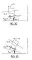
- Figure 3Ais an end view of an on-camber divergent vehicle tendency.
- Figure 3Bis an end view of an automotive vehicle in an off-camber divergent condition.
- Figure 3Cis an end view of a vehicle in an on-camber convergent condition.
- Figure 3Dis an end view of a vehicle in an off-camber convergent condition.
- Figure 4Ais a block diagram of a stability control system.
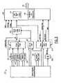
- Figure 4Bis a block diagram of the controller 26 used in the stability control system depicted in Figure 4A .
- Figure 5is a block diagrammatic view of the unit 27 depicted in Figure 4B , which is used for quantitatively and qualitatively determining rollover trend of a vehicle.
- Figure 6is flow chart of the operation of one embodiment of the present invention.
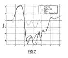
- Figure 7is a plot of true roll angle, relative roll angle, wheel departure angle, and relative roll angle plus wheel departure angle.
- present teachingsmay be used in conjunction with a yaw control system or a rollover control system for an automotive vehicle. However, the present teachings may also be used with a deployment device such as airbag or roll bar.
- Vehicle 10has front right and front left tires 12a and 12b and rear right tires and rear left tires 13a and 13b, respectively.
- the vehicle 10may also have a number of different types of front steering systems 14a and rear steering systems 14b including having each of the front and rear wheels configured with a respective controllable actuator, the front and rear wheels having a conventional type system in which both of the front wheels are controlled together and both of the rear wheels are controlled together, a system having conventional front steering and independently controllable rear steering for each of the wheels, or vice versa.
- the systemmay also be used with active/semi-active suspension systems, anti-roll bar or other safety devices deployed or activated upon sensing predetermined dynamic conditions of the vehicle.
- the sensing system 16is part of a control system 18.
- the sensing system 16may use a standard yaw stability control sensor set (including lateral acceleration sensor, yaw rate sensor, steering angle sensor and wheel speed sensor) together with a roll rate sensor and a longitudinal acceleration sensor.
- the various sensorswill be further described below.
- the wheel speed sensors 20are mounted at each corner of the vehicle, and the rest of the sensors of sensing system 16 may be mounted directly on the center of gravity of the vehicle body, along the directions x,y and z shown in Figure 1 .
- the frame from b 1 , b 2 and b 3is called a body frame 22, whose origin is located at the center of gravity of the car body, with the b 1 corresponding to the x axis pointing forward, b 2 corresponding to the y axis pointing off the driving side (to the left), and the b 3 corresponding to the z axis pointing upward.
- the angular rates of the car bodyare denoted about their respective axes as ⁇ x for the roll rate, ⁇ y for the pitch rate and ⁇ z for the yaw rate.
- the calculations set forth hereinmay take place in an inertial frame 24 that may be derived from the body frame 22 as described below.
- the angular rate sensors and the acceleration sensorsare mounted on the vehicle car body along the body frame directions b 1 , b 2 and b 3 , which are the x-y-z axes of the vehicle's sprung mass.
- the longitudinal acceleration sensor 36is mounted on the car body located at the center of gravity, with its sensing direction along b 1 -axis, whose output is denoted as a x .
- the lateral acceleration sensor 32is mounted on the car body located at the center of gravity, with its sensing direction along b 2 -axis, whose output is denoted as a y .
- the other frame used in the following discussionincludes the road frame, as depicted in Figure 1 .
- the road frame system r 1 r 2 r 3is fixed on the driven road surface, where the r 3 axis is along the average road normal direction computed from the normal directions of the four-tire/road contact patches.
- the Euler angles of the body frame b 1 b 2 b 3 with respect to the road frame r 1 r 2 r 3are denoted as ⁇ xr, ⁇ yr and ⁇ zr , which are also called the relative Euler angles.
- the present teachingdetermines a wheel departure angle ⁇ wda' which is the angle from the axle or the wheel axis to the road surface 11. Also shown is a reference road bank angle ⁇ bank , which is shown relative to the vehicle 10 on a road surface.
- the vehicle 10has a vehicle body 10a and vehicle suspension 10b.
- the relative roll angle ⁇ xris the angle between the wheel axle and the body 10a.
- the global roll angle ⁇ xis the angle between the horizontal plane (e.g., at sea level) and the vehicle body 10a.
- vehicle 10is illustrated in an on-camber divergent state.
- the on-camber divergent staterefers to the vehicle having a greater than 0 wheel departure angle, a greater than 0 relative roll angle, and a moment represented by arrow 25 tending to increase the relative roll angle and the wheel departure angle.
- the bank angleis less than 0.
- a bank angle of less than 0, a wheel departure angle greater than 0, and a relative roll angle greater than 0is shown with a roll moment 25 acting to the left.
- the vehicleis in an on-camber convergent state. That is, the convergent state refers to the vehicle tending towards not overturning.
- a roll stability control system 18is illustrated in further detail having a controller 26 used for receiving information from a number of sensors which may include a yaw rate sensor 28, a speed sensor 20, a lateral acceleration sensor 32, a roll rate sensor 34, a steering angle sensor (hand wheel position) 35, a longitudinal acceleration sensor 36, and steering angle position sensor 37.
- sensorswhich may include a yaw rate sensor 28, a speed sensor 20, a lateral acceleration sensor 32, a roll rate sensor 34, a steering angle sensor (hand wheel position) 35, a longitudinal acceleration sensor 36, and steering angle position sensor 37.
- the sensorsare located at the center of gravity of the vehicle. Those skilled in the art will recognize that the sensors may also be located off the center of gravity and translated equivalently thereto.
- Safety device 38may control an airbag 40, an active braking system 41, an active front steering system 42, an active rear steering system 43, an active suspension system 44, and an active anti-roll bar system 45, or combinations thereof.
- Each of the systems 40-45may have their own controllers for activating each one.
- the safety system 38may be at least the active braking system 41.
- Roll rate sensor 34may sense the roll condition of the vehicle based on sensing the height of one or more points on the vehicle relative to the road surface. Sensors that may be used to achieve this include a radar-based proximity sensor, a laser-based proximity sensor and a sonar-based proximity sensor.
- Roll rate sensor 34may also sense the roll condition based on sensing the linear or rotational relative displacement or displacement velocity of one or more of the suspension chassis components which may include a linear height or travel sensor, a rotary height or travel sensor, a wheel speed sensor used to look for a change in velocity, a steering wheel position sensor, a steering wheel velocity sensor and a driver heading command input from an electronic component that may include steer by wire using a hand wheel or joy stick.
- the suspension chassis componentswhich may include a linear height or travel sensor, a rotary height or travel sensor, a wheel speed sensor used to look for a change in velocity, a steering wheel position sensor, a steering wheel velocity sensor and a driver heading command input from an electronic component that may include steer by wire using a hand wheel or joy stick.
- the roll conditionmay also be sensed by sensing the force or torque associated with the loading condition of one or more suspension or chassis components including a pressure transducer in active air suspension, a shock absorber sensor such as a load cell, a strain gauge, the steering system absolute or relative motor load, the steering system pressure of the hydraulic lines, a tire lateral force sensor or sensors, a longitudinal tire force sensor, a vertical tire force sensor or a tire sidewall torsion sensor.
- a pressure transducer in active air suspensiona shock absorber sensor such as a load cell, a strain gauge, the steering system absolute or relative motor load, the steering system pressure of the hydraulic lines, a tire lateral force sensor or sensors, a longitudinal tire force sensor, a vertical tire force sensor or a tire sidewall torsion sensor.
- the roll condition of the vehiclemay also be established by one or more of the following translational or rotational positions, velocities or accelerations of the vehicle including a roll gyro, the roll rate sensor 34, the yaw rate sensor 28, the lateral acceleration sensor 32, a vertical acceleration sensor, a vehicle longitudinal acceleration sensor, lateral or vertical speed sensor including a wheel-based speed sensor, a radar-based speed sensor, a sonar-based speed sensor, a laser-based speed sensor or an optical-based speed sensor.
- controller 26determines a roll condition and controls any one or more of the safety devices 40-45.
- Speed sensor 20may be one of a variety of speed sensors known to those skilled in the art.
- a suitable speed sensor 20may include a sensor at every wheel that is averaged by controller 26.
- the controller 26translates the wheel speeds into the speed of the vehicle. Yaw rate, steering angle, wheel speed and possibly a slip angle estimate at each wheel may be translated back to the speed of the vehicle at the center of gravity.
- Various other algorithmsare known to those skilled in the art. For example, if speed is determined while speeding up or braking around a corner, the lowest or highest wheel speed may not be used because of its error.
- a transmission sensormay be used to determine vehicle speed.
- controller 26is illustrated in further detail.
- controller 26There are two major functions in controller 26: the rollover trend determination, which is called a sensor fusion unit, 27A and the feedback control command unit 27B.
- the sensor fusion unit 27Acan be further decomposed as a wheel lift detector 50, a transition detector 52 and a vehicle roll angle calculator 66.
- the sensor fusion unit 27Areceives the various sensor signals, 20, 28, 32, 34, 35, 36, 37 and integrates all the sensor signals with the calculated signals to generate signals suitable for roll stability control algorithms. From the various sensor signals wheel lift detection may be determined by the wheel lift detector 50. Wheel lift detector 50 includes both active wheel lift detection and active wheel lift detection, and wheel grounding condition detection. The modules described below may be implemented in hardware or software in a general purpose computer (microprocessor). From the wheel lift detection module 50, a determination of whether each wheel is absolutely grounded, possibly grounded, possibly lifted, or absolutely lifted may be determined. Transition detection module 52 is used to detect whether the vehicle is experiencing aggressive maneuver due to sudden steering wheel inputs from the driver.
- the sensorsmay also be used to determine a relative roll angle in relative roll angle module 54.
- Relative roll anglemay be determined in many ways. One way is to use the roll acceleration module 58 in conjunction with the lateral acceleration sensor. As described above, the relative roll angle may be determined from the roll conditions described above.
- the various sensor signalsmay also be used to determine a relative pitch angle in relative pitch angle module 56 and a roll acceleration in roll acceleration module 58.
- the outputs of the wheel lift detection module 50, the transition detection module 52, and the relative roll angle module 54are used to determine a wheel departure angle in wheel departure angle module 60.
- Various sensor signals and the relative pitch angle in relative pitch angle module 56are used to determine a relative velocity total in module 62.
- the road reference bank angle block 64determines the bank angle.
- the relative pitch angle, the roll acceleration, and various other sensor signals as described beloware used to determine the road reference bank angle.
- Other inputsmay include a roll stability control event (RSC) and/or the presence of a recent yaw stability control event, and the wheel lifting and/or grounding flags.
- RSCroll stability control event
- the global roll angle of the vehicleis determined in global roll angle module 66.
- the relative roll angle, the wheel departure angle, and the roll velocity total blocksare all inputs to the global roll angle total module 66.
- the global roll angle total blockdetermines the global roll angle ⁇ x .
- An output module 68receives the global roll angle total module 66 and the road reference bank angle from the road reference bank angle module 64.
- a roll signal for controlis developed in roll signal module 70.
- the roll signal for controlis illustrated as arrow 72.
- a sensitizing and desensitizing module 74may also be included in the output module 68 to adjust the roll signal for control.
- the reference bank angle estimateis calculated.
- the objective of the reference bank estimateis to track a robust but rough indication of the road bank angle experienced during driving in both stable and highly dynamic situations, and which is in favor for roll stability control. That is, this reference bank angle is adjusted based on the vehicle driving condition and the vehicle roll condition. Most importantly, when compared to the global roll estimate, it is intended to capture the occurrence and physical magnitude of a divergent roll condition (two wheel lift) should it occur. This signal is intended to be used as a comparator against the global roll estimate for calculating the error signal which is fed back to roll stability controller 26.
- the wheel departure angle, ⁇ wdabetween the axle or axis of the wheels and the average road surface is computed. This angle tries to fill the gap left when the relative roll angle is calculated in the relative roll angle module 54.
- the present embodimentallows a determination of the relative roll angle between the vehicle body and the road surface during a potential rollover event particularly where one or two inside wheels are lifted. This variable is used to boost roll_signal_for_control (the true relative roll angle between the vehicle body and the road surface) which is fed to the output module 68 for computing feedback control command. If this calculated value is less than the actual wheel departure angle, it might reduce the needed control command (under-control); if thus calculated value is greater than the actual wheel departure angle, it might increase the needed control command (over-control).
- step 80The external inputs to the wheel departure block 60 are obtained in step 80:
- step 82the relative roll angle ⁇ xr is determined.
- Predefined Calibratable Parameter Definitionsare determined in step 86.
- Wheel departure angle smoothing ratio⁇ , in the present example a value of 1.1 is used.
- Relative roll angle threshold for starting wheel departure angle computation during initial wheel lifting: ⁇ 1 where ⁇ 1A yb 1 *ROLL_GRADIENT and A yb 1 reflects the threshold for the percentage of ROLL_GRADIENT. In this example, a value of 75% is used.
- a local temporary variable usedis the Wheel departure angle intermediate value: ⁇ wda -int .
- the relative roll calculated from the relative roll angle module 54 in step 82may not capture the true relative roll angle between the vehicle body and the road due to lateral acceleration saturation and gravity component in the lateral accelerometer.
- Figure 2shows the angles involved in this case.
- the relative roll angle ⁇ xris the angle due to suspension height variation (also called chassis roll angle or suspension roll angle) which is intended to capture the relative roll between the axle and the vehicle body.
- the global roll angle ⁇ xis the roll angle of the vehicle body with respect to the sea level.
- the wheel departure angle ⁇ wdais used to capture the relative roll angle between the axle and the road surface.
- the road bank angle ⁇ bankis the relative angle between the road surface and the sea level.
- Equation (1)only two variables are known: the total roll angle velocity ⁇ x (RV tot ) and the suspension relative roll angle ⁇ xr . Using these known values the wheel departure angle ⁇ wda is computed.
- the relative roll angle ⁇ xr and relative pitchmay be determined as set forth in U.S. patent 6,556,908 .
- ⁇ y-susp and ⁇ x-suspcan be calculated as described in the following.
- RRA_RAW k1 c 1 ⁇ ⁇ ⁇ x k - c 0 c 1 ⁇ a y k
- RPA_RAW k1 d 1 ⁇ ⁇ ⁇ ⁇ y k - d 0 d 1 ⁇ a x k
- the estimates of ⁇ x - susp ( k +1) and ⁇ y - susp ( k +1)may be computed from their values in the kth sampling instant (past values) and the current and past values of RRA_RAW and RPA_RAW.
- the increased magnitude of delta road bank caseis considered, i.e., the magnitude of the road bank is greater than the magnitude of the road bank at the time of entering wheel lifting. Since increased magnitude of the road bank helps stabilize the vehicle for on-camber driving ( Figs 3a , 3c ), hence less likely the control will be needed. While for off-camber driving ( Fig 3B and 3D ), increased magnitude of road bank will worsen the stability of the vehicle and it needs special control attention. Assume the vehicle is turning left. In this case, ⁇ bank > 0 ' and the actual wheel departure angle ⁇ wda is positive.
- ⁇ wda - ⁇ ⁇ wda- ⁇ ⁇ ⁇ bank ⁇ 0 or say the magnitude of the calculated wheel departure angle ⁇ wda is greater than the actual wheel departure angle.
- the magnitude of the road bankis decreasing, i.e., the magnitude of the road bank is less than the magnitude of the road bank at the time of entering wheel lifting. Since decreased magnitude of road bank helps stabilize the vehicle for off-camber driving, control is less likely to be needed. While for on-camber driving, decreased magnitude of road bank will worsen the stability of the vehicle and control is needed. Assume the vehicle is turning left. In this case, ⁇ bank > 0, and the actual wheel departure angle ⁇ wda is positive. Therefore (10) is true, i.e., the magnitude of the calculated wheel departure angle ⁇ wda is greater than the actual wheel departure angle. Hence the error does not have adverse effect. Assume the vehicle is turning right.
- the error due to small magnitude of the delta road bankdoes not reduce control effort when the control is most likely needed.
- equation (8)thus identifies the time in which the wheels lift at t 0 and the time in which the wheels are no longer lifted, time instant t f , or say the conditions where the wheel lifting can be detected in steps 88 and 90. That is, (8) may be theoretically implemented as in step 92 as in the following:
- the wheel departure angleis determined when the relative roll angle is greater than or equal to 0 and the left side wheel (0) and (2) are absolutely lifted or the relative roll angle is less than zero and the right side wheels are absolutely lifted.
- the above computationmay end up with an under-estimated ⁇ wda due to the fact that integration is delayed. Therefore, there is a need to extend the absolutely lifted condition beyond the time set by the wheel lifting status by a predetermined time in step 94.
- the predetermined timesare determined by the thresholds.
- the following flagis used to extend wheel lifting condition to include conditions involving relative roll angle and the past value of the wheel departure angle.
- step 96the integration will be terminated in step 96, i.e., the wheel departure angle computation will be terminated through the following
Landscapes
- Engineering & Computer Science (AREA)
- Mechanical Engineering (AREA)
- Transportation (AREA)
- Automation & Control Theory (AREA)
- Physics & Mathematics (AREA)
- Mathematical Physics (AREA)
- Chemical & Material Sciences (AREA)
- Combustion & Propulsion (AREA)
- Control Of Driving Devices And Active Controlling Of Vehicle (AREA)
- Vehicle Body Suspensions (AREA)
- Regulating Braking Force (AREA)
Description
- The present invention relates generally to a control apparatus for controlling a system of an automotive vehicle in response to sensed dynamic behavior, and more specifically, to a method and apparatus for controlling the roll characteristics of the vehicle by characterizing the wheel departure angle on which the vehicle is having a potential rollover event.
- Dynamic control systems for automotive vehicles have recently begun to be offered on various products. Dynamic control systems typically control the yaw of the vehicle by controlling the braking effort at the various wheels of the vehicle. Yaw control systems typically compare the desired direction of the vehicle based upon the steering wheel angle and the direction of travel. By regulating the amount of braking at each corner of the vehicle, the desired direction of travel may be maintained. Typically, the dynamic control systems do not address roll of the vehicle. For high profile vehicles in particular, it would be desirable to control the rollover characteristic of the vehicle to maintain the vehicle position with respect to the road. That is, it is desirable to maintain contact of each of the four tires of the vehicle on the road.
- In vehicle roll stability control it is desired to alter the vehicle attitude such that its motion along the roll direction is prevented from achieving a predetermined limit (rollover limit) with the aid of the actuation from the available active systems such as controllable brake system, steering system and suspension system. Although the vehicle attitude is well defined, direct measurement is usually impossible.
- There are two types of vehicle attitudes needed to be distinguished. One is the so-called global attitude, which is sensed by the angular rate sensors. The other is the relative attitude, which measures the relative angular positions of the vehicle with respect to the road surface on which the vehicle is driven. The global attitude of the vehicle is relative to an earth frame (or called the inertia frame), sea level, or a flat road. It can be directly related to the three angular rate gyro sensors. While the relative attitude of the vehicle measures the relative angular positions of the vehicle with respect to the road surface, which are always of various terrains. Unlike the global attitude, there are no gyro-type sensors that can be directly related to the relative attitude. A reasonable estimate is that a successful relative attitude sensing system utilizes both the gyro-type sensors (when the road becomes flat, the relative attitude sensing system recovers the global attitude) and some other sensor signals.
- One reason to distinguish relative and global attitude is due to the fact that vehicles are usually driven on a three-dimensional road surface of different terrains, not always on a flat road surface. Driving on a road surface with a large road bank does increase the rollover tendency, i.e., a large output from the global attitude sensing system might well imply an uncontrollable rollover event regardless of the flat road driving and the 3-D road driving. However driving on a three-dimensional road with moderate road bank angle, the global attitude may not be able to provide enough fidelity for a rollover event to be distinguished. Vehicular rollover happens when one side of the vehicle is lifted from the road surface with a long duration of time without returning back. If a vehicle is driven on a banked road, the global attitude sensing system will pick up certain attitude information even when the vehicle does not experience any wheel lifting (four wheels are always contacting the road surface). Hence a measure of the relative angular positions of the vehicle with respect to the portion of the road surface on which the vehicle is driven provides more fidelity than global attitude to sense the rollover event when the vehicle is driven on a road with a moderate bank angle. Such an angle is called body-to-road roll angle and it is used as one of the key variables in the roll stability control module to compute the amount of actuation needed for preventing untripped rollover event.
- When the vehicle does not have one side lifted,
U.S. patent 6556908 does provide a method to calculate the relative attitudes and their accuracy may be affected by the vehicle loading, suspension and tire conditions. However, during a potential rollover event, such a relative roll angle is not a good measure of the true relative roll angle between vehicle body and the road surface. If the vehicle has large loading variations (especially roof loading), potential inaccuracy could cause false activations in roll stability controls. - During a potential rollover event, one or two wheels on the inside of the vehicle turn are up in the air and there is an angle between the axle of the lifted wheel and road surface. Such an angle is called a wheel departure angle. If such a wheel departure can be somehow characterized, the true body-to-road roll angle can be conceptually obtained as the sum of the wheel departure angle and the relative roll angle calculated in
U.S. patent 6,556,908 . - Another way to capture the true body-to-road roll angle is to use the resultant angle obtained by subtracting the road bank angle for the global roll angle calculated for example in
U.S. patent application publication No. 20030065430 . Although this method is theoretically feasible, it has inevitable drawbacks. The first drawback lies in the computation of the road bank angle, since there is no robust and accurate computation of road banks using the existing sensor set. Secondly, the global roll angle computation as shown inU.S. patent application publication No. 20030065430 may be affected by the accuracy of the low frequency bank angle estimation. - Therefore, the aforementioned two methods of computing the body-to-road roll angle may not deliver accurate enough body-to-road roll angle for roll stability control purpose in certain situations. Because each of the individual methods described above does provide accurate measure with certain conditions, a sensor fusion algorithm would be a way to obtain an angle good for roll stability control. Such a sensor fusion method needs to integrate the various angles and conduct signal sensitizing and desensitizing, which may include the computations of (i) global roll angle as discussed in
U.S. patent application publication No. 20030065430 ; (ii) relative roll angle as discussed inU.S. patent 6,556,908 ; (iii) a rough characterization of the road bank angle, which is called a reference road bank angle); (iv) wheel departure angle; (v) body-to-road roll angle; (vi) transition and rollover condition. - The aforementioned computation is not only good for roll stability control, but also for other applications. For example, the reference road bank angle could be used in an active anti-roll-bar control, the yaw stability control, etc. An active roll control system using a controlled anti-roll-bar does not respond suitably to the side bank in the conventional setting, since the presence of road side bank cannot be detected and the system therefore responds to a side bank as if the vehicle were cornering. This can result in unnecessary power consumption for the active anti-roll-bar system. In order to eliminate this,
U.S. patent 6,282,471 provides a very crude estimation of the road side bank using lateral acceleration sensor and vehicle reference speed. A vehicle driven on a road with a sharp side bank may cause false activation for the yaw stability control system and/or roll stability control system due to the fact that large lateral motion is determined through sensor signals even if the vehicle is driven in steady state condition on the banked road. - Therefore, it is desirable in vehicle dynamics control, especially for roll stability control to detect accurately a wheel departure angle so as to accurately predict the true roll position of the vehicle to properly activate the vehicle control systems.
EP 11 108 34 discloses a roll over stability control for an automotive vehicle. The control system includes a plurality of sensors sensing the dynamic conditions of the vehicle and a controller that controls a distributed brake pressure to reduce a tire moment so that the net moment of the vehicle is counter to the roll direction. The controller determines a roll angle estimate in response to lateral acceleration, roll rate, vehicle speed and yaw rate. The controller changes a tire force vector using a steering angle change in response.US 6, 278, 930 discloses a device for controlling spin/driftout of vehicle compatability with roll control. The device calculates first target braking forces to be applied to vehicle wheels for stabilising the vehicle against a turn instability, second target braking force, for stabilising the vehicle against a roll instability, and target everall braking forces, by integrating the first and second target braking forces.US 6,192, 305 discloses a rollover sensing apparatus and method, correcting the measured roll rate signals as a function of the estimated yaw rate and estimated pitch angle.- Because each of the individual methods described above does provide accurate measure with certain conditions, a sensor fusion algorithm would be a way to obtain an angle good for roll stability control. Such a sensor fusion method needs to integrate the various angles and conduct signal sensitizing and desensitizing, which may include the computations of (i) global roll angle as discussed in
U.S. patent application publication No. 20030065430 ; (ii) relative roll angle as discussed inU.S. patent 6,556,908 ; (iii) a rough characterization of the road bank angle (which is called a reference road bank angle); (iv) wheel departure angle; (v) body-to-road roll angle; (vi) transition and rollover condition. - In one embodiment, a method of controlling an automotive vehicle as claimed in
claim 1 is provided. - One advantage of the invention is that the sensors and signals available in a roll stability control system are used to determine the wheel departure angle. Further, the processing involved in the wheel departure angle uses little processing resources. Another advantage is the wheel lifting and grounding status are used in the determination which may be set to extend beyond the actual time the wheels are lifted to account for processing delays (sensitizing) during wheel lifting and to reset the wheel departure angle to zero (desensitizing) during wheel grounding.
- Other advantages and features of the present invention will become apparent when viewed in light of the detailed description of the preferred embodiment when taken in conjunction with the attached drawings and appended claims.
Figure 1 is a diagrammatic view of a vehicle with variable vectors and coordinator frames.Figure 2 is an end view of an automotive vehicle on a bank with definitions of various angles including global roll angle, relative roll angle, wheel departure angle (WDA), road bank angle and body-to-road angle.Figure 3A is an end view of an on-camber divergent vehicle tendency.Figure 3B is an end view of an automotive vehicle in an off-camber divergent condition.Figure 3C is an end view of a vehicle in an on-camber convergent condition.Figure 3D is an end view of a vehicle in an off-camber convergent condition.Figure 4A is a block diagram of a stability control system.Figure 4B is a block diagram of thecontroller 26 used in the stability control system depicted inFigure 4A .Figure 5 is a block diagrammatic view of theunit 27 depicted inFigure 4B , which is used for quantitatively and qualitatively determining rollover trend of a vehicle.Figure 6 is flow chart of the operation of one embodiment of the present invention.Figure 7 is a plot of true roll angle, relative roll angle, wheel departure angle, and relative roll angle plus wheel departure angle.- In the following figures the same reference numerals will be used to identify the same components. The present teachings may be used in conjunction with a yaw control system or a rollover control system for an automotive vehicle. However, the present teachings may also be used with a deployment device such as airbag or roll bar.
- Referring to
Figure 1 , anautomotive vehicle 10 on a road surface 11 with a safety system is illustrated with the various forces and moments thereon.Vehicle 10 has front right and front left tires 12a and 12b and rear right tires and rear left tires 13a and 13b, respectively. Thevehicle 10 may also have a number of different types offront steering systems 14a andrear steering systems 14b including having each of the front and rear wheels configured with a respective controllable actuator, the front and rear wheels having a conventional type system in which both of the front wheels are controlled together and both of the rear wheels are controlled together, a system having conventional front steering and independently controllable rear steering for each of the wheels, or vice versa. Generally, the vehicle has a weight represented asMg at the center of gravity of the vehicle, whereg=9.8m/s2 andM is the total mass of the vehicle. - As mentioned above, the system may also be used with active/semi-active suspension systems, anti-roll bar or other safety devices deployed or activated upon sensing predetermined dynamic conditions of the vehicle.
- The
sensing system 16 is part of acontrol system 18. Thesensing system 16 may use a standard yaw stability control sensor set (including lateral acceleration sensor, yaw rate sensor, steering angle sensor and wheel speed sensor) together with a roll rate sensor and a longitudinal acceleration sensor. The various sensors will be further described below. Thewheel speed sensors 20 are mounted at each corner of the vehicle, and the rest of the sensors ofsensing system 16 may be mounted directly on the center of gravity of the vehicle body, along the directionsx,y andz shown inFigure 1 . As those skilled in the art will recognize, the frame fromb1,b2 andb3 is called abody frame 22, whose origin is located at the center of gravity of the car body, with theb1 corresponding to thex axis pointing forward,b2 corresponding to they axis pointing off the driving side (to the left), and theb3 corresponding to thez axis pointing upward. The angular rates of the car body are denoted about their respective axes as ωx for the roll rate, ωy for the pitch rate and ωz for the yaw rate. The calculations set forth herein may take place in aninertial frame 24 that may be derived from thebody frame 22 as described below. - The angular rate sensors and the acceleration sensors are mounted on the vehicle car body along the body frame directionsb1,b2 andb3, which are thex-y-z axes of the vehicle's sprung mass.
- The longitudinal acceleration sensor 36 is mounted on the car body located at the center of gravity, with its sensing direction alongb1-axis, whose output is denoted asax. The
lateral acceleration sensor 32 is mounted on the car body located at the center of gravity, with its sensing direction alongb2-axis, whose output is denoted asay. - The other frame used in the following discussion includes the road frame, as depicted in
Figure 1 . The road frame systemr1r2r3 is fixed on the driven road surface, where ther3 axis is along the average road normal direction computed from the normal directions of the four-tire/road contact patches. - In the following discussion, the Euler angles of the body frameb1b2b3 with respect to the road framer1r2r3 are denoted asθxr,θyr and θzr, which are also called the relative Euler angles.
- Referring now to
Figure 2 , the relationship of the various angles of thevehicle 10 relative to the road surface 11 is illustrated. The present teaching determines a wheel departure angleθwda' which is the angle from the axle or the wheel axis to the road surface 11. Also shown is a reference road bank angleθbank, which is shown relative to thevehicle 10 on a road surface. Thevehicle 10 has avehicle body 10a and vehicle suspension 10b. The relative roll angleθxr is the angle between the wheel axle and thebody 10a. The global roll angle θx is the angle between the horizontal plane (e.g., at sea level) and thevehicle body 10a. - Referring now to
Figure 3A ,vehicle 10 is illustrated in an on-camber divergent state. The on-camber divergent state refers to the vehicle having a greater than 0 wheel departure angle, a greater than 0 relative roll angle, and a moment represented byarrow 25 tending to increase the relative roll angle and the wheel departure angle. In this example, the bank angle is less than 0. - In
Figure 3B , when the bank angle is greater than 0, the wheel departure angle is greater than 0, the relative roll angle is greater than 0 and the moment is also to the right or increasing the relative roll angle and the wheel departure angle, the vehicle is in an off-camber divergent state. - Referring now to
Figure 3C , a bank angle of less than 0, a wheel departure angle greater than 0, and a relative roll angle greater than 0 is shown with aroll moment 25 acting to the left. Thus, the vehicle is in an on-camber convergent state. That is, the convergent state refers to the vehicle tending towards not overturning. - Referring now to
Figure 3D , when the bank angle is greater than 0, the wheel departure angle is greater than 0, and the relative roll angle is greater than 0 and the roll moment is tending to the left, the vehicle is in an off-camber convergent state. That is, the vehicle is tending toward not rolling over. - Referring now to
Figure 4A , one embodiment of a rollstability control system 18 is illustrated in further detail having acontroller 26 used for receiving information from a number of sensors which may include ayaw rate sensor 28, aspeed sensor 20, alateral acceleration sensor 32, aroll rate sensor 34, a steering angle sensor (hand wheel position) 35, a longitudinal acceleration sensor 36, and steeringangle position sensor 37. - In one embodiment, the sensors are located at the center of gravity of the vehicle. Those skilled in the art will recognize that the sensors may also be located off the center of gravity and translated equivalently thereto.
- Lateral acceleration, roll orientation and speed may be obtained using a global positioning system (GPS). Based upon inputs from the sensors,
controller 26 may control asafety device 38. Depending on the desired sensitivity of the system and various other factors, not all thesensors Safety device 38 may control anairbag 40, an active braking system 41, an active front steering system 42, an active rear steering system 43, an active suspension system 44, and an activeanti-roll bar system 45, or combinations thereof. Each of the systems 40-45 may have their own controllers for activating each one. As mentioned above, thesafety system 38 may be at least the active braking system 41. Roll rate sensor 34 may sense the roll condition of the vehicle based on sensing the height of one or more points on the vehicle relative to the road surface. Sensors that may be used to achieve this include a radar-based proximity sensor, a laser-based proximity sensor and a sonar-based proximity sensor.Roll rate sensor 34 may also sense the roll condition based on sensing the linear or rotational relative displacement or displacement velocity of one or more of the suspension chassis components which may include a linear height or travel sensor, a rotary height or travel sensor, a wheel speed sensor used to look for a change in velocity, a steering wheel position sensor, a steering wheel velocity sensor and a driver heading command input from an electronic component that may include steer by wire using a hand wheel or joy stick.- The roll condition may also be sensed by sensing the force or torque associated with the loading condition of one or more suspension or chassis components including a pressure transducer in active air suspension, a shock absorber sensor such as a load cell, a strain gauge, the steering system absolute or relative motor load, the steering system pressure of the hydraulic lines, a tire lateral force sensor or sensors, a longitudinal tire force sensor, a vertical tire force sensor or a tire sidewall torsion sensor.
- The roll condition of the vehicle may also be established by one or more of the following translational or rotational positions, velocities or accelerations of the vehicle including a roll gyro, the
roll rate sensor 34, theyaw rate sensor 28, thelateral acceleration sensor 32, a vertical acceleration sensor, a vehicle longitudinal acceleration sensor, lateral or vertical speed sensor including a wheel-based speed sensor, a radar-based speed sensor, a sonar-based speed sensor, a laser-based speed sensor or an optical-based speed sensor. - Based on the inputs from
sensors controller 26 determines a roll condition and controls any one or more of the safety devices 40-45. Speed sensor 20 may be one of a variety of speed sensors known to those skilled in the art. For example, asuitable speed sensor 20 may include a sensor at every wheel that is averaged bycontroller 26. Thecontroller 26 translates the wheel speeds into the speed of the vehicle. Yaw rate, steering angle, wheel speed and possibly a slip angle estimate at each wheel may be translated back to the speed of the vehicle at the center of gravity. Various other algorithms are known to those skilled in the art. For example, if speed is determined while speeding up or braking around a corner, the lowest or highest wheel speed may not be used because of its error. Also, a transmission sensor may be used to determine vehicle speed.- Referring now to
Figures 4A and 4B ,controller 26 is illustrated in further detail. There are two major functions in controller 26: the rollover trend determination, which is called a sensor fusion unit, 27A and the feedbackcontrol command unit 27B. Thesensor fusion unit 27A can be further decomposed as awheel lift detector 50, atransition detector 52 and a vehicleroll angle calculator 66. - Referring now to
Figure 5 , thesensor fusion unit 27A is illustrated in further detail. Thesensor fusion unit 27A receives the various sensor signals, 20, 28, 32, 34, 35, 36, 37 and integrates all the sensor signals with the calculated signals to generate signals suitable for roll stability control algorithms. From the various sensor signals wheel lift detection may be determined by thewheel lift detector 50.Wheel lift detector 50 includes both active wheel lift detection and active wheel lift detection, and wheel grounding condition detection. The modules described below may be implemented in hardware or software in a general purpose computer (microprocessor). From the wheellift detection module 50, a determination of whether each wheel is absolutely grounded, possibly grounded, possibly lifted, or absolutely lifted may be determined.Transition detection module 52 is used to detect whether the vehicle is experiencing aggressive maneuver due to sudden steering wheel inputs from the driver. The sensors may also be used to determine a relative roll angle in relativeroll angle module 54. Relative roll angle may be determined in many ways. One way is to use theroll acceleration module 58 in conjunction with the lateral acceleration sensor. As described above, the relative roll angle may be determined from the roll conditions described above. - The various sensor signals may also be used to determine a relative pitch angle in relative
pitch angle module 56 and a roll acceleration inroll acceleration module 58. The outputs of the wheellift detection module 50, thetransition detection module 52, and the relativeroll angle module 54 are used to determine a wheel departure angle in wheel departure angle module 60. Various sensor signals and the relative pitch angle in relativepitch angle module 56 are used to determine a relative velocity total inmodule 62. The road referencebank angle block 64 determines the bank angle. The relative pitch angle, the roll acceleration, and various other sensor signals as described below are used to determine the road reference bank angle. Other inputs may include a roll stability control event (RSC) and/or the presence of a recent yaw stability control event, and the wheel lifting and/or grounding flags. - The global roll angle of the vehicle is determined in global
roll angle module 66. The relative roll angle, the wheel departure angle, and the roll velocity total blocks are all inputs to the global roll angletotal module 66. The global roll angle total block determines the global roll angleθx. Anoutput module 68 receives the global roll angletotal module 66 and the road reference bank angle from the road referencebank angle module 64. A roll signal for control is developed inroll signal module 70. The roll signal for control is illustrated asarrow 72. A sensitizing and desensitizingmodule 74 may also be included in theoutput module 68 to adjust the roll signal for control. - In the reference road
bank angle module 64, the reference bank angle estimate is calculated. The objective of the reference bank estimate is to track a robust but rough indication of the road bank angle experienced during driving in both stable and highly dynamic situations, and which is in favor for roll stability control. That is, this reference bank angle is adjusted based on the vehicle driving condition and the vehicle roll condition. Most importantly, when compared to the global roll estimate, it is intended to capture the occurrence and physical magnitude of a divergent roll condition (two wheel lift) should it occur. This signal is intended to be used as a comparator against the global roll estimate for calculating the error signal which is fed back to rollstability controller 26. - Referring now to
Figure 6 , the operation of the wheel departure angle block or module 60 is described in further detail. The wheel departure angle,θwda, between the axle or axis of the wheels and the average road surface is computed. This angle tries to fill the gap left when the relative roll angle is calculated in the relativeroll angle module 54. The present embodiment allows a determination of the relative roll angle between the vehicle body and the road surface during a potential rollover event particularly where one or two inside wheels are lifted. This variable is used to boost roll_signal_for_control (the true relative roll angle between the vehicle body and the road surface) which is fed to theoutput module 68 for computing feedback control command. If this calculated value is less than the actual wheel departure angle, it might reduce the needed control command (under-control); if thus calculated value is greater than the actual wheel departure angle, it might increase the needed control command (over-control). - The external inputs to the wheel departure block 60 are obtained in step 80:
- Roll velocity total:RVtot, (sometimes written as θ̇x)
- Past value of the wheel departure angle:θwda
- Transition flags:Stransition(0) for front left wheel andStransition(1) for front right wheel.
- In
step 82, the relative roll angleθxr is determined. - In
step 84 the wheel lift status flags:Swld (i).
If the ith wheel is absolutely grounded, thenSwld (i) = ABSOLUTELY_GROUNDED
If the ith wheel is in the edge of grounding,Swld (i) = POSSIBLY _ GROUNDED
If the ith wheel is absolutely lifted, thenSwld (i) = ABSOLUTELY _LIFTED
If the ith wheel is in the edge of liftingSwld (i) = POSSIBLY _ LIFTED
If the ith wheel's status cannot be firmly identified,Swld (i) = NO_INDICATION - Predefined Calibratable Parameter Definitions are determined in
step 86.
Wheel departure angle smoothing ratio: ρ, in the present example a value of 1.1 is used.
Relative roll angle threshold for starting wheel departure angle computation during transition maneuver (transition flag is active) pre-charge active:Θtransition-active
whereΘtransition-active =Ayp * ROLL_GRADIENT andAyp reflects the threshold for the percentage of ROLL_GRADIENT,default value 40%.
Relative roll angle threshold for starting wheel departure angle computation during initial wheel lifting: Θ1
where Θ1=Ayb1*ROLL_GRADIENT andAyb1 reflects the threshold for the percentage of ROLL_GRADIENT. In this example, a value of 75% is used.
Relative roll angle threshold for starting wheel departure angle computation during medium wheel lifting: Θ2
whereΘ2 =Ayb2*ROLL_GRADIENT andAyb2 reflects the threshold for the percentage of ROLL_GRADIENT. In this example, a value of 50% is used.
Wheel departure angle threshold for starting wheel departure angle computation during medium wheel lifting: Ψ2
whereΨ2 =Ayw2*ROLL_GRADIENT andAyw2 reflects the threshold for the percentage of ROLL_GRADIENT. In this example, a value of 25% is used.
Relative roll angle threshold for starting wheel departure angle computation during high wheel lifting: Θ3
whereΘ3 =Ayb3*ROLL_GRADIENT andAyb3 reflects the threshold for the percentage of ROLL_GRADIENT. In this example, a value of 40% is used.
Wheel departure angle threshold for starting wheel departure angle computation during high wheel lifting: Ψ3
where Ψ3 =Ayw3* ROLL _ GRADIENT andAyw3 reflects the threshold for the percentage of ROLL_GRADIENT. In this example, a value of 75% is used.
Wheel departure angle filter coefficient: α. In this example, a value of 511/512 is used.
Wheel departure angle lower bound: Ψmin . In this example, a value of -10 degrees is used.
Wheel departure angle upper bound: Ψmax . In this example, a value of 10 degrees is used.
Loop time:p_LOOP_TIME_SEC = 0.007. - A local temporary variable used is the Wheel departure angle intermediate value: θwda-int.
- When the vehicle is highly lifted on one side (inside in a turn), the relative roll calculated from the relative
roll angle module 54 instep 82 may not capture the true relative roll angle between the vehicle body and the road due to lateral acceleration saturation and gravity component in the lateral accelerometer.Figure 2 shows the angles involved in this case. The relative roll angleθxr is the angle due to suspension height variation (also called chassis roll angle or suspension roll angle) which is intended to capture the relative roll between the axle and the vehicle body. The global roll angle θx is the roll angle of the vehicle body with respect to the sea level. The wheel departure angleθwda is used to capture the relative roll angle between the axle and the road surface. The road bank angleθbank is the relative angle between the road surface and the sea level. - Considering the angles in
Figs. 2 and3 , the following relationship is true:
- Notice that in equation (1) only two variables are known: the total roll angle velocity θ̇x (RVtot) and the suspension relative roll angleθxr. Using these known values the wheel departure angleθwda is computed.
- The roll velocity totalRVtot can be computed from roll rate sensor signal, yaw rate sensor signal and the pitch rate sensor signal in the following formula:

- The relative roll angleθxr and relative pitch may be determined as set forth in
U.S. patent 6,556,908 .


US6556908 for detail),ω̂y is an estimation of the pitch rate signal, which can be calculated as


- Equation (1) may be rewritten as the following


- The wheel lift status is also factored into the determination of the wheel departure angle through (3). Assume at time instantt0, one or two wheels of the vehicle start to depart from contacting the road surface (based on wheel lifting information or any other indication) and before time instantt0 all the wheels of the vehicle are grounded. Let the road bank angle at timet0 beb0, then

- At time instantt such thatt0≤t≤tf (tf is the time instant when the lifted wheels come back to contact the road surface), (5) is subtracted from (3) to obtain the following

- If the vehicle is on level ground thenθbank= 0, or the vehicle is on a constant road bank (i.e.,θbank(t)=θb0), then (6) is the same as


- The approximateθ̂wda computed in (8) is a good approximation of the actual wheel departure angleθwda if the change in the road bank angle (delta road bankΔθbank )

- The following is a list of cases where the change in the road bank angle is zero or very low:
- If the vehicle is driven on a level ground, then the delta road bank is zero andθ̂wda is the actual departure angle.
- If the vehicle is not driven on a transient road bank, or say the vehicle is driven on a steady state bank road, then the delta road bank is close to zero andθ̂wda is close to the actual wheel departure angle.
- If during wheel lifting, the road bank does not change much in comparison with the road bank at the initial wheel lifting time instant, then the delta road bank can be negligible andθ̂wda is close to the actual wheel departure angle.
- If during wheel lifting the vehicle is driven very aggressive such that the roll velocity due to the road bank is much smaller than the roll velocity due to the wheel departure and the relative roll, then the delta road bank can be negligible and θ̂wda is close to actual wheel departure angle.
- The aforementioned cases cover large portion of the scenarios where the wheel lifting could happen. Notice that since the delta road bank comes from taking awayθb0 from the actual road bank, and wheel lift event usually happens in seconds, the magnitude of delta road bank is relatively much smaller than the actual road bank. Therefore, if in cases where delta road bank is non-zero, its magnitude should be less than the magnitude ofθ̂wda. As shown below, a small non-zero error may not cause an adverse control effect.
- First, the increased magnitude of delta road bank case is considered, i.e., the magnitude of the road bank is greater than the magnitude of the road bank at the time of entering wheel lifting. Since increased magnitude of the road bank helps stabilize the vehicle for on-camber driving (
Figs 3a ,3c ), hence less likely the control will be needed. While for off-camber driving (Fig 3B and3D ), increased magnitude of road bank will worsen the stability of the vehicle and it needs special control attention. Assume the vehicle is turning left. In this case,Δθbank>0' and the actual wheel departure angleθwda is positive. Therefore,

- When the magnitude of the road bank is decreasing, i.e., the magnitude of the road bank is less than the magnitude of the road bank at the time of entering wheel lifting. Since decreased magnitude of road bank helps stabilize the vehicle for off-camber driving, control is less likely to be needed. While for on-camber driving, decreased magnitude of road bank will worsen the stability of the vehicle and control is needed. Assume the vehicle is turning left. In this case,Δθbank > 0, and the actual wheel departure angleθwda is positive. Therefore (10) is true, i.e., the magnitude of the calculated wheel departure angleθ̂wda is greater than the actual wheel departure angle. Hence the error does not have adverse effect. Assume the vehicle is turning right. In this case,Δθbank<0, and the actual wheel departure angleθwda is negative. Therefore (11) is true, i.e., the magnitude of the calculated wheel departure angleθ̂wda is greater than the actual wheel departure angle. Hence the error does not have adverse effect.
- The error due to small magnitude of the delta road bank does not reduce control effort when the control is most likely needed.
- A more accurate implementation of equation (8) thus identifies the time in which the wheels lift att0 and the time in which the wheels are no longer lifted, time instanttf, or say the conditions where the wheel lifting can be detected in
steps 
- In the above, the wheel departure angle is determined when the relative roll angle is greater than or equal to 0 and the left side wheel (0) and (2) are absolutely lifted or the relative roll angle is less than zero and the right side wheels are absolutely lifted.
- Considering the current wheel lift statusSwld(i)s fori=0,1,2,3 sometimes have delays, the above computation may end up with an under-estimated θwda due to the fact that integration is delayed. Therefore, there is a need to extend the absolutely lifted condition beyond the time set by the wheel lifting status by a predetermined time in
step 94. The predetermined times are determined by the thresholds. The following flag is used to extend wheel lifting condition to include conditions involving relative roll angle and the past value of the wheel departure angle.
- Consider the fact that during an aggressive maneuver which activates the pre-charge control, the wheel lifting is likely to happen, further time extension of the wheel lifting condition is needed

- On the other hand, the pure integration here might introduce numerical error, hence the pure integration is replaced by the following high-pass-filtered integration

- Notice that the wheel departure angle is assumed to be in the same trend as the relative roll angle. Also, a previous or first wheel departure is used. That is, the previous equation adds an incremental change to the previous wheel departure angle. In order to achieve this, the sign enforcement and a numerical limitation are implemented as in the following:

- When the wheel lifting conditions are not met, or the vehicle potentially does not have any lifted wheels and is beyond the time described above, the integration will be terminated in
step 96, i.e., the wheel departure angle computation will be terminated through the following
- The following is a detailed implementation of the afore-mentioned algorithm to compute the wheel departure angle θwda.

- Thus, as can be seen, the various threshold conditions must be met before determining the wheel departure angle from the formula θwda-int = α* θwda-int +RV *p_LOOP_TIME_SEC. I f the conditions are not met the θwda is set to 0.
- Referring now to
Figure 7 , a comparison between the true body roll angle (from a laser sensor) and the calculated roll angle by adding the wheel departure angle to the relative roll angle was performed in a vehicle. The laser sensor was used in a test to confirm the results set forth herein. A laser sensor is expensive and is not used in production. As can be seen, the true roll and theθwda plus relative roll angle are nearly equal. This indicates that the calculated wheel departure angleθwda does fill the gap between the vehicle true roll angle and the calculated relative roll angleθxr during potential rollover event. - While particular embodiments of the invention have been shown and described, numerous variations and alternate embodiments will occur to those skilled in the art. Accordingly, it is intended that the invention be limited only in terms of the appended claims.


Claims (12)
- A method of controlling an automotive vehicle (10) on a road surface, the automotive vehicle having an axle, comprising:determining a total roll angle velocity as a function of yaw rate, roll rate and pitch angle;determining a wheel departure angle between the wheel axle and the road surface, as a function of the total roll angle velocity; andcontrolling the vehicle (10) using the wheel departure angle.
- A method as recited in claim 1 further comprising determining a relative roll angle; and
wherein controlling the vehicle (10) comprises controlling the vehicle using a total roll angle velocity and the relative roll angle. - A method as recited in claim 2 wherein determining a relative roll angle comprises determining a relative roll angle as a function of a roll rate and a lateral acceleration.
- A method as recited in claim 2 wherein determining a total roll angle velocity is performed when the relative roll angle is within a first predetermined threshold and the wheel departure angle is within a second predetermined threshold.
- A method as recited in claim 4 wherein the first threshold and second thresholds are a function of a roll gradient.
- A method as recited in claim 1 wherein determining a total roll angle velocity comprises determining a response to a roll rate.
- A method as recited in claim 1 wherein determining a total roll angle velocity comprises determining a response to a roll rate and a yaw rate.
- A method as recited in claim 1 wherein determining a total roll angle velocity comprises determining a response to a roll rate, a yaw rate and a pitch rate.
- A method as recited in claim 1 wherein determining a total roll angle velocity comprises determining a response to a roll rate and a previous wheel departure angle.
- A method as recited in claim 1 wherein determining a total roll angle velocity comprises determining a response to a roll rate, a previous wheel departure angle and a time constant.
- A method as recited in claim 1 wherein determining a total roll angle velocity is performed in response to a wheel lift status.
- A method as recited in claim 1 wherein determining a total roll angle velocity is performed in response to a brake precharge status.
Applications Claiming Priority (10)
| Application Number | Priority Date | Filing Date | Title |
|---|---|---|---|
| US610278 | 2000-07-06 | ||
| US40026102P | 2002-08-01 | 2002-08-01 | |
| US40037602P | 2002-08-01 | 2002-08-01 | |
| US40017202P | 2002-08-01 | 2002-08-01 | |
| US40037502P | 2002-08-01 | 2002-08-01 | |
| US400376P | 2002-08-01 | ||
| US400261P | 2002-08-01 | ||
| US400375P | 2002-08-01 | ||
| US400172P | 2002-08-01 | ||
| US10/610,278US7194351B2 (en) | 2002-08-01 | 2003-06-30 | System and method for determining a wheel departure angle for a rollover control system |
Publications (2)
| Publication Number | Publication Date |
|---|---|
| EP1386807A1 EP1386807A1 (en) | 2004-02-04 |
| EP1386807B1true EP1386807B1 (en) | 2009-03-18 |
Family
ID=30119459
Family Applications (1)
| Application Number | Title | Priority Date | Filing Date |
|---|---|---|---|
| EP03254819AExpired - LifetimeEP1386807B1 (en) | 2002-08-01 | 2003-07-31 | System and method for determining a wheel departure angle for a rollover control system |
Country Status (3)
| Country | Link |
|---|---|
| US (1) | US7194351B2 (en) |
| EP (1) | EP1386807B1 (en) |
| DE (1) | DE60326678D1 (en) |
Families Citing this family (24)
| Publication number | Priority date | Publication date | Assignee | Title |
|---|---|---|---|---|
| US7054727B2 (en)* | 2002-05-03 | 2006-05-30 | Burke E. Porter Machinery Company | Method of measuring a propensity of a vehicle to roll over |
| US9162656B2 (en)* | 2003-02-26 | 2015-10-20 | Ford Global Technologies, Llc | Active driven wheel lift identification for an automotive vehicle |
| US7653471B2 (en)* | 2003-02-26 | 2010-01-26 | Ford Global Technologies, Llc | Active driven wheel lift identification for an automotive vehicle |
| JP4145741B2 (en)* | 2003-07-03 | 2008-09-03 | 三菱電機株式会社 | Vehicle rollover discrimination device and vehicle rollover discrimination method |
| US7502675B2 (en)* | 2004-04-01 | 2009-03-10 | Delphi Technologies, Inc. | Feedforward control of motor vehicle roll angle |
| WO2006023819A2 (en)* | 2004-08-19 | 2006-03-02 | United States Postal Service | Delivery operations information system with route and unit maintenance |
| US7191047B2 (en)* | 2004-09-27 | 2007-03-13 | Delphi Technologies, Inc. | Motor vehicle control using a dynamic feedforward approach |
| US7640081B2 (en)* | 2004-10-01 | 2009-12-29 | Ford Global Technologies, Llc | Roll stability control using four-wheel drive |
| DE102005054141A1 (en)* | 2005-11-14 | 2007-05-16 | Bosch Gmbh Robert | Method for determining the tire diameter of a motor vehicle |
| DE102006000733A1 (en)* | 2006-01-04 | 2007-07-12 | Conti Temic Microelectronic Gmbh | Method and device for determining a triggering decision for restraining means of a vehicle |
| JP2009523640A (en)* | 2006-01-13 | 2009-06-25 | ティーケー ホールディングス インコーポレーテッド | Control module |
| US8712639B2 (en)* | 2006-08-30 | 2014-04-29 | Ford Global Technologies | Integrated control system for stability control of yaw, roll and lateral motion of a driving vehicle using an integrated sensing system to determine longitudinal velocity |
| US8321088B2 (en) | 2006-08-30 | 2012-11-27 | Ford Global Technologies | Integrated control system for stability control of yaw, roll and lateral motion of a driving vehicle using an integrated sensing system to determine lateral velocity |
| US7970512B2 (en) | 2006-08-30 | 2011-06-28 | Ford Global Technologies | Integrated control system for stability control of yaw, roll and lateral motion of a driving vehicle using an integrated sensing system with pitch information |
| US7573375B2 (en)* | 2007-05-02 | 2009-08-11 | Paccar Inc | Rollover prediction and warning method |
| DE102008041417A1 (en)* | 2008-08-21 | 2010-02-25 | Zf Lenksysteme Gmbh | Electric servo steering, particularly power steering for vehicle, comprises axially slidable component, which is driven by servomotor supported in frame, where servomotor is controlled by control or regulating device |
| US9283825B2 (en) | 2014-02-25 | 2016-03-15 | Isam Mousa | System, method, and apparatus to prevent commercial vehicle rollover |
| US10328939B2 (en)* | 2017-04-19 | 2019-06-25 | Hall Labs Llc | Big air electronic control module |
| KR102460857B1 (en)* | 2018-03-27 | 2022-10-31 | 현대모비스 주식회사 | Apparatus for determining rollover conditions of vehicle and method thereof |
| US20190299909A1 (en)* | 2018-03-29 | 2019-10-03 | GM Global Technology Operations LLC | Inflatable control apparatus and deployment method thereof |
| CN110861649A (en)* | 2019-11-20 | 2020-03-06 | 徐州徐工矿业机械有限公司 | System and method for monitoring driving behavior of driver of electric transmission mining dump truck |
| CN111522293B (en)* | 2020-05-08 | 2022-12-13 | 衡阳镭目科技有限责任公司 | Automatic tilting control method and system for metallurgical tank |
| CN112113774B (en)* | 2020-06-30 | 2023-03-14 | 上汽通用五菱汽车股份有限公司 | Ramp detection method, detection terminal and storage medium |
| KR20230057000A (en)* | 2021-10-21 | 2023-04-28 | 현대모비스 주식회사 | Apparatus for estimating road profile and method thereof |
Family Cites Families (215)
| Publication number | Priority date | Publication date | Assignee | Title |
|---|---|---|---|---|
| US2917126A (en) | 1957-04-04 | 1959-12-15 | Nolan Phillips | Driving control safety mechanism for tractors |
| US3604273A (en) | 1968-11-25 | 1971-09-14 | Aviat Electric Ltd | Angular rate sensor |
| US3608925A (en) | 1969-05-07 | 1971-09-28 | Peter H Murphy | Apparatus for offsetting centrifugal force affecting motor vehicles |
| US3899028A (en) | 1972-03-30 | 1975-08-12 | Systron Donner Corp | Angular position sensing and control system, apparatus and method |
| US4023864A (en) | 1973-09-20 | 1977-05-17 | Lang Davis Industries, Inc. | Automatic stability control system with strain gauge sensors |
| US3972543A (en) | 1974-12-06 | 1976-08-03 | The Bendix Corporation | Combination vehicle yaw stabilizer |
| US3948567A (en) | 1975-02-12 | 1976-04-06 | The Bendix Corporation | Sway control means for a trailer |
| USRE30550E (en) | 1975-11-06 | 1981-03-24 | Durrell U. Howard | Automatic trailer sway sensing and brake applying system |
| FR2425342A1 (en) | 1978-05-12 | 1979-12-07 | Saint Marcel Ste Metallurg | Heavy vehicle anti-overturning retarder - has centrifugal acceleration detector emitting signal to solenoid operated brake valve and alarm circuit |
| SU816849A1 (en) | 1979-05-07 | 1981-03-30 | Ленинградский Ордена Трудовогокрасного Знамени Сельскохозяйственныйинститут | Device for preventing toppling of a vehicle |
| JPS6015015B2 (en) | 1979-06-29 | 1985-04-17 | 株式会社 レオ技研 | Road moisture detection device |
| JPS58152793A (en) | 1982-03-05 | 1983-09-10 | ティー・シー・エム株式会社 | Device for preventing turning-sideways of transport car |
| US4592656A (en)* | 1983-07-05 | 1986-06-03 | Honeywell, Inc. | Ring laser angular rate sensor with modulated scattered waves |
| JPS60133526A (en) | 1983-12-21 | 1985-07-16 | Mitsubishi Metal Corp | Magnetic recording medium |
| JPS60163770A (en) | 1984-02-02 | 1985-08-26 | Honda Motor Co Ltd | vehicle steering system |
| US4592565A (en) | 1984-10-17 | 1986-06-03 | Leo Eagle | Apparatus for detecting an overturning moment in a moving vehicle, and jackknifing in a trailer-truck combination |
| JPH06104455B2 (en) | 1985-03-15 | 1994-12-21 | 日産自動車株式会社 | Vehicle motion condition estimation device |
| US4650212A (en) | 1985-03-20 | 1987-03-17 | Mazda Motor Corporation | Vehicle suspension system |
| EP0198450B1 (en) | 1985-04-13 | 1988-12-21 | Nissan Motor Co., Ltd. | Vehicle control system for controlling side slip angle and yaw rate gain |
| JP2532059B2 (en) | 1985-09-13 | 1996-09-11 | 日産自動車株式会社 | Vehicle suspension control device |
| JPH0629039B2 (en) | 1986-01-10 | 1994-04-20 | 日産自動車株式会社 | Vehicle motion state estimation device |
| DE3606797C2 (en) | 1986-03-01 | 2000-11-23 | Bosch Gmbh Robert | Device and method for controlling, in particular for limiting, the driving speed of a road vehicle |
| US4761022A (en) | 1986-03-08 | 1988-08-02 | Toyota Jidosha Kabushiki Kaisha | Suspension controller for improved turning |
| JPH0694253B2 (en) | 1986-03-17 | 1994-11-24 | トヨタ自動車株式会社 | Roll control device for vehicle |
| DE3616907A1 (en) | 1986-05-20 | 1987-11-26 | Hans Prof Dr Ing Marko | Device for controlling the speed of revolution of a motor vehicle about the vertical axis |
| JPS62291067A (en) | 1986-06-10 | 1987-12-17 | Nec Corp | Manufacture of thin film transistor |
| JPS63116918U (en) | 1987-01-19 | 1988-07-28 | ||
| JPS63203456A (en) | 1987-02-18 | 1988-08-23 | Mazda Motor Corp | Control device for driving force of automobile |
| JPH0419078Y2 (en) | 1987-03-26 | 1992-04-28 | ||
| JPH0829649B2 (en) | 1987-03-31 | 1996-03-27 | 日産自動車株式会社 | Active suspension device |
| DE3821610A1 (en) | 1988-06-27 | 1989-12-28 | Bayerische Motoren Werke Ag | CONTROL DEVICE FOR STABILIZING A VEHICLE |
| JPS6432918A (en) | 1987-07-28 | 1989-02-02 | Mitsubishi Motors Corp | Active suspension controller |
| DE3826982C2 (en) | 1987-08-10 | 2000-11-30 | Denso Corp | Auxiliary steering system connected to an anti-lock control system for use in motor vehicles |
| DE3877118T2 (en) | 1987-10-15 | 1993-07-01 | Mazda Motor | DEVICE FOR DETERMINING THE FRICTION FACTOR FOR VEHICLES. |
| JPH01122716A (en) | 1987-11-05 | 1989-05-16 | Hitachi Ltd | Automobile active suspension control system |
| DE3738221A1 (en) | 1987-11-11 | 1989-06-08 | Bayerische Motoren Werke Ag | METHOD AND DEVICE FOR DETECTING THE STATE OF A ROAD |
| JP2618250B2 (en) | 1987-12-22 | 1997-06-11 | 富士重工業株式会社 | Traction control device |
| DE3804587A1 (en) | 1988-02-13 | 1989-08-24 | Daimler Benz Ag | ADDITIONAL STEERING |
| DE3805589A1 (en) | 1988-02-23 | 1989-08-31 | Lucas Ind Plc | METHOD AND DEVICE FOR CONTROLLING A BRAKE SYSTEM FOR HEAVY VEHICLES |
| DE3815938C2 (en) | 1988-05-10 | 1996-09-19 | Bayerische Motoren Werke Ag | Acceleration sensor for vehicles |
| US4898431A (en) | 1988-06-15 | 1990-02-06 | Aisin Seiki Kabushiki Kaisha | Brake controlling system |
| US5313389A (en) | 1988-09-13 | 1994-05-17 | Aisin Seiki Kabushiki Kaisha | Fail-safe mechanism for vehicle stability augmentation steering system |
| EP0434679B1 (en) | 1988-09-17 | 1993-05-12 | Robert Bosch Gmbh | Apparatus for tripping a system for the protection of occupants of a vehicle |
| JP2565384B2 (en) | 1988-09-30 | 1996-12-18 | 富士重工業株式会社 | Control device for automobile active suspension |
| GB8825540D0 (en) | 1988-11-01 | 1988-12-07 | Jaguar Cars | Air bag restraint systems |
| JPH0732331Y2 (en) | 1989-01-18 | 1995-07-26 | 日産自動車株式会社 | Vehicle steering control device |
| US4998593A (en) | 1989-03-31 | 1991-03-12 | Aisin Seiki Kabushiki Kaisha | Steering and brake controlling system |
| US5239868A (en) | 1989-05-19 | 1993-08-31 | Matsushita Electric Industrial Co., Ltd. | Angular rate detecting device |
| JP2000344085A (en) | 1999-06-03 | 2000-12-12 | Toyota Motor Corp | Wheel control status display |
| JP2867448B2 (en) | 1989-08-11 | 1999-03-08 | 株式会社日立製作所 | Active suspension control device |
| JPH0396468A (en) | 1989-09-07 | 1991-04-22 | Honda Motor Co Ltd | Estimation method for fore and aft acceleration and deceleration of body |
| FR2655299B1 (en) | 1989-12-01 | 1992-02-21 | Renault | SAFETY SYSTEM FOR A MOTOR VEHICLE. |
| JPH0833408B2 (en) | 1990-03-29 | 1996-03-29 | 株式会社日立製作所 | Angle detection device, translational acceleration detection device, and vehicle control device |
| US5265020A (en) | 1990-04-20 | 1993-11-23 | Mazda Motor Corporation | Torque distribution control apparatus for four wheel drive |
| JP2762711B2 (en) | 1990-07-02 | 1998-06-04 | 日産自動車株式会社 | Vehicle braking behavior compensator |
| JP2600986B2 (en) | 1990-07-06 | 1997-04-16 | 三菱自動車工業株式会社 | Rear wheel steering control method |
| JP2679415B2 (en) | 1990-12-21 | 1997-11-19 | 日産自動車株式会社 | Vehicle braking force left / right distribution control device |
| US5408411A (en) | 1991-01-18 | 1995-04-18 | Hitachi, Ltd. | System for predicting behavior of automotive vehicle and for controlling vehicular behavior based thereon |
| US5189920A (en)* | 1991-03-21 | 1993-03-02 | Electronics & Space Corp. | Corner stability testing apparatus |
| DE4121954A1 (en) | 1991-07-03 | 1993-01-07 | Bosch Gmbh Robert | METHOD FOR OBTAINING THE YEAR SPEED AND / OR THE LATERAL SPEED |
| GB2257403A (en) | 1991-07-06 | 1993-01-13 | Gloster Saro Ltd | Road vehicle stability indicating system. |
| US5282134A (en) | 1991-08-19 | 1994-01-25 | Automotive Systems Laboratory, Inc. | Slant transform/signal space crash discriminator |
| US5324102A (en) | 1991-10-18 | 1994-06-28 | Fag Kugelfischer Georg Schafer Kgaa | Method and apparatus for regulating the braking force of motorcycles |
| JPH05131946A (en) | 1991-11-13 | 1993-05-28 | Toyota Motor Corp | Rear wheel steering control device |
| US5335176A (en) | 1991-12-02 | 1994-08-02 | Koyo Seiko Co., Ltd. | Safety system for vehicles |
| JP3197330B2 (en) | 1992-04-10 | 2001-08-13 | 本田技研工業株式会社 | Vehicle driving force control device |
| US5548536A (en) | 1992-05-16 | 1996-08-20 | Daimler-Benz Ag | Method for determining quantities which characterize the driving behavior |
| JPH0616117A (en) | 1992-06-30 | 1994-01-25 | Honda Motor Co Ltd | Wheel longitudinal force control method in vehicle |
| DE4226746C1 (en) | 1992-08-13 | 1993-10-07 | Daimler Benz Ag | Method for determining a driving-dependent steering angle |
| DE4227886A1 (en) | 1992-08-22 | 1994-02-24 | Sel Alcatel Ag | Inclinometer for vehicle with body - contains inertial system or fibre optical gyroscope |
| DE4228893B4 (en) | 1992-08-29 | 2004-04-08 | Robert Bosch Gmbh | System for influencing the driving dynamics of a motor vehicle |
| US5278761A (en) | 1992-11-12 | 1994-01-11 | Ford Motor Company | Method for vehicular wheel spin control that adapts to different road traction characteristics |
| JP2882232B2 (en) | 1993-03-17 | 1999-04-12 | 三菱自動車工業株式会社 | Vehicle weight center slip angle measuring device |
| EP0662601B1 (en) | 1993-03-30 | 1998-12-30 | OKADA, Kazuhiro | Multishaft angular velocity sensor |
| DE4335979A1 (en) | 1993-10-21 | 1995-04-27 | Telefunken Microelectron | Security management system (SMS) |
| DE4342732A1 (en) | 1993-12-15 | 1995-06-22 | Anton Ellinghaus Maschinenfabr | Tilt sensor for tanker vehicle |
| JP3303500B2 (en) | 1994-02-02 | 2002-07-22 | トヨタ自動車株式会社 | Vehicle behavior control device |
| DE4405379A1 (en) | 1994-02-19 | 1995-08-24 | Bosch Gmbh Robert | ABS braking system for vehicle |
| KR100207106B1 (en) | 1994-04-06 | 1999-07-15 | 정몽규 | Method and apparatus of taper for automobile testing road |
| KR950028978A (en) | 1994-04-06 | 1995-11-22 | 전성원 | Shift pattern control device and method for steep slope and steep curve |
| US5446658A (en) | 1994-06-22 | 1995-08-29 | General Motors Corporation | Method and apparatus for estimating incline and bank angles of a road surface |
| JP3116738B2 (en) | 1994-07-28 | 2000-12-11 | トヨタ自動車株式会社 | Vehicle behavior control device |
| US5610575A (en) | 1994-08-25 | 1997-03-11 | Automotive Systems Laboratory, Inc. | Method and system for detecting vehicle roll-over |
| US5602734A (en) | 1994-09-23 | 1997-02-11 | Advanced Safety Concepts, Inc. | Automobile air bag systems |
| JP3050061B2 (en) | 1994-10-25 | 2000-06-05 | トヨタ自動車株式会社 | Occupant restraint |
| US5732377A (en) | 1994-11-25 | 1998-03-24 | Itt Automotive Europe Gmbh | Process for controlling driving stability with a yaw rate sensor equipped with two lateral acceleration meters |
| DE19515051B4 (en) | 1994-11-25 | 2006-08-31 | Continental Teves Ag & Co. Ohg | Method for determining an additional yaw moment |
| US5732379A (en) | 1994-11-25 | 1998-03-24 | Itt Automotive Europe Gmbh | Brake system for a motor vehicle with yaw moment control |
| US5732378A (en) | 1994-11-25 | 1998-03-24 | Itt Automotive Europe Gmbh | Method for determining a wheel brake pressure |
| US5549328A (en) | 1995-01-17 | 1996-08-27 | Gabriel Ride Control Products, Inc. | Roll control system |
| JPH08258588A (en) | 1995-03-27 | 1996-10-08 | Mazda Motor Corp | Road surface condition detecting device in vehicle |
| JP3042360B2 (en) | 1995-04-13 | 2000-05-15 | 日本ビクター株式会社 | Magnetic head reversing device |
| JP3463415B2 (en) | 1995-06-22 | 2003-11-05 | 日産自動車株式会社 | Vehicle yawing behavior control device |
| US5648903A (en) | 1995-07-10 | 1997-07-15 | Ford Global Technologies, Inc. | Four wheel steering control utilizing front/rear tire longitudinal slip difference |
| DE19529539A1 (en) | 1995-08-11 | 1997-02-13 | Man Nutzfahrzeuge Ag | Procedure for the ON-BOARD determination of vehicle dynamic safety reserves of commercial vehicles |
| FI108084B (en) | 1995-09-08 | 2001-11-15 | Vaisala Oyj | Method and apparatus for measuring the properties of a road surface |
| JP3248411B2 (en) | 1995-10-11 | 2002-01-21 | トヨタ自動車株式会社 | Vehicle behavior control device |
| JP3248413B2 (en) | 1995-10-18 | 2002-01-21 | トヨタ自動車株式会社 | Vehicle behavior control device |
| JP3008833B2 (en) | 1995-10-25 | 2000-02-14 | トヨタ自動車株式会社 | Estimation device for vehicle body skidding speed |
| JP3627325B2 (en) | 1995-11-17 | 2005-03-09 | アイシン精機株式会社 | Vehicle motion control device |
| JP3533420B2 (en) | 1995-12-05 | 2004-05-31 | トヨタ自動車株式会社 | Brake control device |
| DE19602879C1 (en) | 1996-01-29 | 1997-08-07 | Knorr Bremse Systeme | Method for detecting the risk of a vehicle tipping over |
| AUPN786796A0 (en) | 1996-02-05 | 1996-02-29 | Verward Pty Ltd (trading as Brooks Merchants) | Vehicle seat |
| DE19609176A1 (en) | 1996-03-11 | 1997-09-18 | Bosch Gmbh Robert | Method and arrangement for detecting a vehicle rollover |
| DE19609717A1 (en) | 1996-03-13 | 1997-09-18 | Bosch Gmbh Robert | Arrangement for detecting rollover processes in vehicles |
| US5787375A (en) | 1996-04-01 | 1998-07-28 | Ford Global Technologies, Inc. | Method for determining steering position of automotive steering mechanism |
| DE19615294A1 (en) | 1996-04-18 | 1997-10-23 | Bosch Gmbh Robert | Method and device for controlling the braking force on at least one wheel of a vehicle |
| US5742918A (en) | 1996-04-26 | 1998-04-21 | Ford Global Technologies, Inc. | Method and apparatus for dynamically compensating a lateral acceleration of a motor vehicle |
| US5809434A (en) | 1996-04-26 | 1998-09-15 | Ford Global Technologies, Inc. | Method and apparatus for dynamically determically determining an operating state of a motor vehicle |
| US5742919A (en) | 1996-04-26 | 1998-04-21 | Ford Global Technologies, Inc. | Method and apparatus for dynamically determining a lateral velocity of a motor vehicle |
| JPH09315277A (en) | 1996-05-31 | 1997-12-09 | Unisia Jecs Corp | Vehicle motion control device |
| JP2877084B2 (en) | 1996-07-09 | 1999-03-31 | 三菱自動車工業株式会社 | Braking force control device |
| US5707117A (en) | 1996-07-19 | 1998-01-13 | General Motors Corporation | Active brake control diagnostic |
| DE19655388B4 (en) | 1996-08-16 | 2008-08-14 | Daimler Ag | Vehicle dynamics control system and method |
| DE19634728C1 (en) | 1996-08-28 | 1998-04-02 | Daimler Benz Ag | Vehicle steering |
| US5878357A (en) | 1996-09-03 | 1999-03-02 | Ford Global Technologies, Inc. | Method and apparatus for vehicle yaw rate estimation |
| US5720533A (en) | 1996-10-15 | 1998-02-24 | General Motors Corporation | Brake control system |
| JPH10119743A (en) | 1996-10-23 | 1998-05-12 | Aisin Seiki Co Ltd | Vehicle motion control device |
| JPH10129439A (en) | 1996-10-25 | 1998-05-19 | Aisin Seiki Co Ltd | Vehicle motion control device |
| US5723782A (en) | 1996-11-29 | 1998-03-03 | Bolles, Jr.; Robert C. | Method of land vehicle suspension evaluation and design through roll angle analysis |
| DE19650691C2 (en) | 1996-12-07 | 1998-10-29 | Deutsch Zentr Luft & Raumfahrt | Method for steering assistance for a driver of a road vehicle |
| US5825284A (en) | 1996-12-10 | 1998-10-20 | Rollover Operations, Llc | System and method for the detection of vehicle rollover conditions |
| US5736939A (en) | 1996-12-11 | 1998-04-07 | Caterpillar Inc. | Apparatus and method for determing a condition of a road |
| GB9626045D0 (en) | 1996-12-14 | 1997-01-29 | Rover Group | A vehicle roll stabilising system |
| JP3493568B2 (en) | 1997-02-12 | 2004-02-03 | 光洋精工株式会社 | Car steering system |
| FR2761039B1 (en) | 1997-03-22 | 2002-05-31 | Bosch Gmbh Robert | METHOD AND DEVICE FOR IMPLEMENTING A GUIDANCE SYSTEM OF A MOTOR VEHICLE |
| US6226579B1 (en) | 1997-03-22 | 2001-05-01 | Robert Bosch Gmbh | Method and apparatus for operating a steering system for a motor vehicle |
| US6186267B1 (en) | 1997-03-22 | 2001-02-13 | Robert Bosch Gmbh | Method and apparatus for operating a steering system for a motor vehicle |
| JP3269421B2 (en) | 1997-04-04 | 2002-03-25 | 三菱自動車工業株式会社 | Automatic vehicle deceleration control device |
| JP3045452U (en) | 1997-05-15 | 1998-02-03 | 株式会社ハイランドハウス | Cushioning material using wood shavings |
| JPH10329682A (en) | 1997-06-03 | 1998-12-15 | Mitsubishi Motors Corp | Vehicle rollover prevention device |
| JP3982011B2 (en) | 1997-06-24 | 2007-09-26 | 三菱ふそうトラック・バス株式会社 | Vehicle rollover prevention device |
| PT991543E (en) | 1997-07-01 | 2004-10-29 | Dynamotive L L C | ANTI-ROTATING BRAKING SYSTEM |
| JP3681259B2 (en) | 1997-07-23 | 2005-08-10 | 光洋精工株式会社 | Electric power steering device |
| US6026926A (en) | 1997-07-25 | 2000-02-22 | Honda Giken Kogyo Kabushiki Kaisha | Electric power steering apparatus |
| JPH11194091A (en) | 1997-08-20 | 1999-07-21 | Daimler Benz Ag | Determining method of road surface condition and implementation apparatus thereof |
| DE19744085A1 (en) | 1997-10-06 | 1999-04-08 | Bosch Gmbh Robert | System producing trigger signal for vehicle safety unit with collision with low obstacle |
| DE19744083A1 (en) | 1997-10-06 | 1999-04-08 | Bosch Gmbh Robert | Arrangement for producing trigger signal for safety unit in vehicle with roll operation |
| US6035251A (en) | 1997-11-10 | 2000-03-07 | General Motors Corporation | Brake system control method employing yaw rate and ship angle control |
| DE19751925A1 (en) | 1997-11-22 | 1999-05-27 | Bosch Gmbh Robert | Tilt tendency detection method for vehicles for stabilization and roll-over prevention of heavy duty vehicle |
| DE19751839A1 (en) | 1997-11-22 | 1999-05-27 | Bosch Gmbh Robert | Tilt tendency detection in vehicle |
| DE19751867A1 (en) | 1997-11-22 | 1999-05-27 | Bosch Gmbh Robert | Tilt tendency detection in vehicle |
| DE19751935A1 (en) | 1997-11-22 | 1999-05-27 | Bosch Gmbh Robert | Method and device for determining a quantity describing the center of gravity of a vehicle |
| JPH11170992A (en) | 1997-12-10 | 1999-06-29 | Mitsubishi Motors Corp | Vehicle rollover prevention device |
| WO1999030942A1 (en) | 1997-12-16 | 1999-06-24 | Continental Teves Ag & Co. Ohg | Method for improving tilt stability in a motor vehicle |
| DE19802041A1 (en) | 1998-01-21 | 1999-07-22 | Bosch Gmbh Robert | Procedure for stabilizing car to avoid tipping over, especially for about axis oriented in car's longitudinal direction |
| GB9801780D0 (en) | 1998-01-29 | 1998-03-25 | Rover Group | A roll damper arrangement |
| US5971503A (en) | 1998-02-03 | 1999-10-26 | Ford Global Technologies, Inc. | Hydraulic control unit with ambient temperature compensation during fluid pressure delivery |
| US6038495A (en) | 1998-02-06 | 2000-03-14 | Delco Electronics Corporation | Vehicle rollover sensing using short-term integration |
| US6002974A (en) | 1998-02-06 | 1999-12-14 | Delco Electronics Corporation | Vehicle rollover sensing using extended kalman filter |
| US6002975A (en) | 1998-02-06 | 1999-12-14 | Delco Electronics Corporation | Vehicle rollover sensing |
| JPH11254992A (en) | 1998-03-09 | 1999-09-21 | Mitsubishi Motors Corp | Vehicle rollover tendency determination device and rollover prevention device using the device |
| JP3436119B2 (en) | 1998-03-11 | 2003-08-11 | トヨタ自動車株式会社 | Body roll suppression control device |
| DE19812237C1 (en) | 1998-03-20 | 1999-09-23 | Daimler Chrysler Ag | Method for driving dynamics control on a road vehicle |
| US5946644A (en) | 1998-03-30 | 1999-08-31 | Chrysler Corporation | Steering center indicator device |
| GB9806969D0 (en) | 1998-04-01 | 1998-06-03 | Lucas Ind Plc | Improvements relating to vehicle steering systems |
| KR100572500B1 (en) | 1998-04-07 | 2006-04-24 | 로베르트 보쉬 게엠베하 | Vehicle stabilization method and device |
| JP3369467B2 (en) | 1998-04-24 | 2003-01-20 | 日野自動車株式会社 | Estimation arithmetic unit for height of center of gravity of vehicle |
| JP3345346B2 (en) | 1998-04-24 | 2002-11-18 | 日野自動車株式会社 | Estimation arithmetic unit for height of center of gravity of vehicle |
| US6089344A (en) | 1998-06-01 | 2000-07-18 | Ford Global Technologies, Inc. | Method and apparatus for determining the center position of a steering system |
| GB9812264D0 (en) | 1998-06-09 | 1998-08-05 | Rover Group | Vehicle roll control |
| GB9812274D0 (en) | 1998-06-09 | 1998-08-05 | Rover Group | Hydraulic control systems |
| JP3252797B2 (en) | 1998-06-19 | 2002-02-04 | トヨタ自動車株式会社 | Rollover determination method |
| US6050360A (en) | 1998-06-24 | 2000-04-18 | General Motors Corporation | Apparatus and method for producing a desired return torque in a vehicle power steering system having a rotational steering position sensor |
| US6438464B1 (en) | 1998-07-16 | 2002-08-20 | Continental Teves Ag & Co., Ohg | Method and device for detecting the overturning hazard of a motor vehicle |
| US6198988B1 (en) | 1998-08-10 | 2001-03-06 | Ford Global Technologies, Inc. | Method for detecting an erroneous direction of travel signal |
| US6073065A (en) | 1998-09-04 | 2000-06-06 | Ford Global Technologies, Inc. | Method for detecting a bank angle experienced by a moving vehicle |
| US6169939B1 (en) | 1998-09-08 | 2001-01-02 | Ford Global Technologies, Inc. | Method of generating a vehicle lateral acceleration signal for use in an active tilt control system |
| JP3816679B2 (en) | 1998-09-17 | 2006-08-30 | 株式会社東海理化電機製作所 | Rotation angle detector |
| GB9821064D0 (en) | 1998-09-29 | 1998-11-18 | Rover Group | Vehicle roll control |
| GB2342078B (en) | 1998-09-29 | 2002-05-08 | Rover Group | Vehicle roll control |
| DE19844540A1 (en) | 1998-09-29 | 2000-03-30 | Bosch Gmbh Robert | Arrangements and methods for avoiding rollovers when braking or accelerating for motor vehicles |
| JP3497746B2 (en) | 1998-10-26 | 2004-02-16 | 本田技研工業株式会社 | Electric power steering device |
| US6314329B1 (en) | 1998-11-06 | 2001-11-06 | Visteon Global Technologies, Inc. | Compensation algorithm for initializing yaw rate sensor's zero point offset |
| US6179394B1 (en) | 1998-11-09 | 2001-01-30 | General Motors Corporation | Active brake balance control method |
| US6062336A (en) | 1998-11-13 | 2000-05-16 | General Motors Corporation | Adaptive variable effort power steering system |
| US6292759B1 (en) | 1998-11-19 | 2001-09-18 | Delphi Technologies, Inc. | Vehicle attitude angle estimation using sensed signal blending |
| US6678631B2 (en)* | 1998-11-19 | 2004-01-13 | Delphi Technologies, Inc. | Vehicle attitude angle estimator and method |
| US6161905A (en) | 1998-11-19 | 2000-12-19 | General Motors Corporation | Active brake control including estimation of yaw rate and slip angle |
| US6195606B1 (en) | 1998-12-07 | 2001-02-27 | General Motors Corporation | Vehicle active brake control with bank angle compensation |
| US6185485B1 (en) | 1998-12-22 | 2001-02-06 | Ford Global Technologies, Inc | Relative vehicle platform having synchronized adaptive offset calibration for lateral accelerometer and steering angle sensor |
| US6202009B1 (en) | 1998-12-22 | 2001-03-13 | Ford Global Technologies, Inc. | Method for detecting fault of vehicle motion sensors |
| US6122568A (en) | 1998-12-22 | 2000-09-19 | Ford Global Technologies, Inc. | Method and apparatus for determining the dynamic stability of an automotive vehicle |
| US6144904A (en) | 1998-12-22 | 2000-11-07 | Ford Global Technologies, Inc. | Instant detection / diagnosis of abrupt bias fault in signals of vehicle motion sensors |
| JP2000198453A (en) | 1998-12-29 | 2000-07-18 | Robert Bosch Gmbh | Steer-by-wire steering system for vehicle |
| JP3726557B2 (en) | 1999-05-26 | 2005-12-14 | トヨタ自動車株式会社 | Roll suppression control device for vehicle |
| US6278930B1 (en) | 1999-06-01 | 2001-08-21 | Toyota Jidosha Kabushiki Kaisha | Device for controlling spin/driftout of vehicle compatibly with roll control |
| US6170594B1 (en)* | 1999-06-01 | 2001-01-09 | Micky G. Gilbert | Method and apparatus for reducing vehicle rollover |
| JP3506048B2 (en) | 1999-06-08 | 2004-03-15 | トヨタ自動車株式会社 | Vehicle behavior control device |
| US6141605A (en) | 1999-06-25 | 2000-10-31 | Ford Global Technologies, Inc. | Determining the direction of travel of an automotive vehicle from yaw rate and relative steering wheel angle |
| US6202020B1 (en) | 1999-08-20 | 2001-03-13 | Meritor Heavy Vehicle Systems, Llc | Method and system for determining condition of road |
| JP3463622B2 (en) | 1999-09-14 | 2003-11-05 | トヨタ自動車株式会社 | Vehicle behavior control device |
| US6233510B1 (en) | 1999-10-15 | 2001-05-15 | Meritor Heavy Vehicle Technology, Llc | Method and system for predicting road profile |
| US6332104B1 (en) | 1999-12-21 | 2001-12-18 | Ford Global Technologies, Inc. | Roll over detection for an automotive vehicle |
| US6263261B1 (en) | 1999-12-21 | 2001-07-17 | Ford Global Technologies, Inc. | Roll over stability control for an automotive vehicle |
| US6324446B1 (en) | 1999-12-21 | 2001-11-27 | Ford Global Technologies, Inc. | Roll over stability control for an automotive vehicle |
| DE10000550B4 (en) | 2000-01-08 | 2005-09-15 | Bayerische Motoren Werke Ag | Device for detecting flashovers in a vehicle |
| US6282474B1 (en) | 2000-06-04 | 2001-08-28 | Ford Global Technologies, Inc. | Method and apparatus for detecting rollover of an automotive vehicle |
| US6266596B1 (en) | 2000-06-13 | 2001-07-24 | Caterpillar Inc. | Method and apparatus for controlling a mobile machine during start-up |
| JP4396002B2 (en) | 2000-06-27 | 2010-01-13 | トヨタ自動車株式会社 | Vehicle traction control device |
| JP3960740B2 (en) | 2000-07-31 | 2007-08-15 | トヨタ自動車株式会社 | Brake control device for vehicle |
| US6456194B1 (en)* | 2000-09-21 | 2002-09-24 | Craig D. Carlson | Device and method for sensing and indicating inclination of an automotive vehicle |
| US6397127B1 (en) | 2000-09-25 | 2002-05-28 | Ford Global Technologies, Inc. | Steering actuated wheel lift identification for an automotive vehicle |
| US6356188B1 (en) | 2000-09-25 | 2002-03-12 | Ford Global Technologies, Inc. | Wheel lift identification for an automotive vehicle |
| JP2002107371A (en) | 2000-09-29 | 2002-04-10 | Toyota Motor Corp | Wheel rotation state detector |
| JP2002104149A (en) | 2000-09-29 | 2002-04-10 | Toyota Motor Corp | Wheel rotation state detector |
| US6498976B1 (en) | 2000-10-30 | 2002-12-24 | Freightliner Llc | Vehicle operator advisor system and method |
| US6477480B1 (en) | 2000-11-15 | 2002-11-05 | Ford Global Technologies, Inc. | Method and apparatus for determining lateral velocity of a vehicle |
| JP3736340B2 (en) | 2000-12-14 | 2006-01-18 | トヨタ自動車株式会社 | Vehicle control device |
| US6542073B2 (en)* | 2000-12-20 | 2003-04-01 | Trw Inc. | System and method for sensing vehicle rollover |
| US6433681B1 (en)* | 2000-12-20 | 2002-08-13 | Trw Inc. | Apparatus and method for detecting vehicle rollover having roll-rate switched threshold |
| US6351694B1 (en) | 2001-01-16 | 2002-02-26 | Ford Global Technologies, Inc. | Method for robust estimation of road bank angle |
| US6644454B2 (en) | 2001-01-23 | 2003-11-11 | Toyota Jidosha Kabushiki Kaisha | Running condition control system for vehicle and method |
| US6799092B2 (en) | 2001-02-21 | 2004-09-28 | Ford Global Technologies, Llc | Rollover stability control for an automotive vehicle using rear wheel steering and brake control |
| US6556908B1 (en) | 2002-03-04 | 2003-04-29 | Ford Global Technologies, Inc. | Attitude sensing system for an automotive vehicle relative to the road |
- 2003
- 2003-06-30USUS10/610,278patent/US7194351B2/ennot_activeExpired - Lifetime
- 2003-07-31EPEP03254819Apatent/EP1386807B1/ennot_activeExpired - Lifetime
- 2003-07-31DEDE60326678Tpatent/DE60326678D1/ennot_activeExpired - Lifetime
Also Published As
| Publication number | Publication date |
|---|---|
| US7194351B2 (en) | 2007-03-20 |
| DE60326678D1 (en) | 2009-04-30 |
| EP1386807A1 (en) | 2004-02-04 |
| US20040064236A1 (en) | 2004-04-01 |
Similar Documents
| Publication | Publication Date | Title |
|---|---|---|
| US7079928B2 (en) | System and method for determining a wheel departure angle for a rollover control system with respect to road roll rate and loading misalignment | |
| EP1386807B1 (en) | System and method for determining a wheel departure angle for a rollover control system | |
| US6631317B2 (en) | Attitude sensing system for an automotive vehicle | |
| US7877178B2 (en) | System and method for dynamically determining vehicle loading and vertical loading distance for use in a vehicle dynamic control system | |
| US6718248B2 (en) | System for detecting surface profile of a driving road | |
| EP1346856B1 (en) | A system and method for determining the roll angle of a vehicle | |
| EP1386808B1 (en) | System and method for characterizing vehicle body to road angle for vehicle roll stability control | |
| US8219282B2 (en) | System for dynamically determining vehicle rear/trunk loading for use in a vehicle control system | |
| US7676307B2 (en) | System and method for controlling a safety system of a vehicle in response to conditions sensed by tire sensors related applications | |
| US7109856B2 (en) | Wheel lifted and grounded identification for an automotive vehicle | |
| US7136731B2 (en) | System for determining vehicular relative roll angle during a potential rollover event | |
| US20040041358A1 (en) | Roll over stability control for an automotive vehicle having an active suspension | |
| US6961648B2 (en) | System and method for desensitizing the activation criteria of a rollover control system | |
| EP1386801B1 (en) | System and method for characterizing the road bank for vehicle roll stability control | |
| US7430468B2 (en) | System and method for sensitizing the activation criteria of a rollover control system |
Legal Events
| Date | Code | Title | Description |
|---|---|---|---|
| PUAI | Public reference made under article 153(3) epc to a published international application that has entered the european phase | Free format text:ORIGINAL CODE: 0009012 | |
| AK | Designated contracting states | Kind code of ref document:A1 Designated state(s):AT BE BG CH CY CZ DE DK EE ES FI FR GB GR HU IE IT LI LU MC NL PT RO SE SI SK TR | |
| AX | Request for extension of the european patent | Extension state:AL LT LV MK | |
| 17P | Request for examination filed | Effective date:20040713 | |
| AKX | Designation fees paid | Designated state(s):DE FR GB SE | |
| 17Q | First examination report despatched | Effective date:20050502 | |
| RAP1 | Party data changed (applicant data changed or rights of an application transferred) | Owner name:FORD GLOBAL TECHNOLOGIES, LLC. | |
| 17Q | First examination report despatched | Effective date:20050502 | |
| GRAP | Despatch of communication of intention to grant a patent | Free format text:ORIGINAL CODE: EPIDOSNIGR1 | |
| GRAS | Grant fee paid | Free format text:ORIGINAL CODE: EPIDOSNIGR3 | |
| GRAA | (expected) grant | Free format text:ORIGINAL CODE: 0009210 | |
| AK | Designated contracting states | Kind code of ref document:B1 Designated state(s):DE FR GB SE | |
| REG | Reference to a national code | Ref country code:GB Ref legal event code:FG4D | |
| REF | Corresponds to: | Ref document number:60326678 Country of ref document:DE Date of ref document:20090430 Kind code of ref document:P | |
| REG | Reference to a national code | Ref country code:SE Ref legal event code:TRGR | |
| PGFP | Annual fee paid to national office [announced via postgrant information from national office to epo] | Ref country code:GB Payment date:20090929 Year of fee payment:7 | |
| PLBE | No opposition filed within time limit | Free format text:ORIGINAL CODE: 0009261 | |
| STAA | Information on the status of an ep patent application or granted ep patent | Free format text:STATUS: NO OPPOSITION FILED WITHIN TIME LIMIT | |
| PGFP | Annual fee paid to national office [announced via postgrant information from national office to epo] | Ref country code:SE Payment date:20090929 Year of fee payment:7 | |
| 26N | No opposition filed | Effective date:20091221 | |
| PGFP | Annual fee paid to national office [announced via postgrant information from national office to epo] | Ref country code:FR Payment date:20091029 Year of fee payment:7 | |
| GBPC | Gb: european patent ceased through non-payment of renewal fee | Effective date:20100731 | |
| EUG | Se: european patent has lapsed | ||
| REG | Reference to a national code | Ref country code:FR Ref legal event code:ST Effective date:20110331 | |
| PG25 | Lapsed in a contracting state [announced via postgrant information from national office to epo] | Ref country code:FR Free format text:LAPSE BECAUSE OF NON-PAYMENT OF DUE FEES Effective date:20100802 | |
| PG25 | Lapsed in a contracting state [announced via postgrant information from national office to epo] | Ref country code:GB Free format text:LAPSE BECAUSE OF NON-PAYMENT OF DUE FEES Effective date:20100731 | |
| PG25 | Lapsed in a contracting state [announced via postgrant information from national office to epo] | Ref country code:SE Free format text:LAPSE BECAUSE OF NON-PAYMENT OF DUE FEES Effective date:20100801 | |
| PGFP | Annual fee paid to national office [announced via postgrant information from national office to epo] | Ref country code:DE Payment date:20200615 Year of fee payment:18 | |
| REG | Reference to a national code | Ref country code:DE Ref legal event code:R119 Ref document number:60326678 Country of ref document:DE | |
| PG25 | Lapsed in a contracting state [announced via postgrant information from national office to epo] | Ref country code:DE Free format text:LAPSE BECAUSE OF NON-PAYMENT OF DUE FEES Effective date:20220201 |