EP1386287B1 - Image processing method - Google Patents
Image processing methodDownload PDFInfo
- Publication number
- EP1386287B1 EP1386287B1EP02740241AEP02740241AEP1386287B1EP 1386287 B1EP1386287 B1EP 1386287B1EP 02740241 AEP02740241 AEP 02740241AEP 02740241 AEP02740241 AEP 02740241AEP 1386287 B1EP1386287 B1EP 1386287B1
- Authority
- EP
- European Patent Office
- Prior art keywords
- image
- pixel
- deformation vector
- scaling factor
- processing method
- Prior art date
- Legal status (The legal status is an assumption and is not a legal conclusion. Google has not performed a legal analysis and makes no representation as to the accuracy of the status listed.)
- Expired - Lifetime
Links
Images


Classifications
- G—PHYSICS
- G06—COMPUTING OR CALCULATING; COUNTING
- G06T—IMAGE DATA PROCESSING OR GENERATION, IN GENERAL
- G06T3/00—Geometric image transformations in the plane of the image
- G06T3/18—Image warping, e.g. rearranging pixels individually
Definitions
- the inventionrelates to an image processing method for the optical display of information and / or signals, wherein a source image is transformed into a contrast deformed target image.
- Such methodse.g. in GB-A-2 312 123 are known by the term “warping” algorithms and are used to deform images. It is usually based on a “mesh” as a “warping” mask. Since this requires the provision of vector crowds, these are complicated techniques that naturally have a large storage space requirement and are thus computationally intensive. As a result, the conventional methods according to the state of the art can be used practically only in larger computer systems, so-called “workstations” or the like.
- the inventionis the object of the invention to provide an image processing method of the type mentioned above, which has a lower storage space requirement compared to the prior art and thus in microprocessor-based small devices with relatively small data storage modules, as is the case for example in mobile phones the like , is usable.
- the objectis achieved in procedural terms, characterized in that in a initialization phase within the source image, a deformation direction defining deformation vector is defined and that for the respective image pixels of the source image are determined in each case a corresponding coordinate position in the target image in accordance with a transformation rule functionally dependent on this vector and a scaling factor that takes into account the position of the respective image pixels in relation to this vector.
- a preferred embodiment of the image processing method according to the inventionis that the scaling factor is assigned a substantially elliptical function course such that the deformation vector extends approximately between the focal points of the elliptical function curve.
- the inventive methodis particularly suitable for source images, the natural forms, such as faces, body or the like, exhibit.
- the respective assigned value of the scaling factoris determined according to 1 - ((S- ⁇ L) / ( ⁇ L)), where ⁇ is an adjustable constant, and if the respective determined value is greater than zero, this positive value is assigned to the respective image pixel, while otherwise for this image pixel the value of the scaling factor is set to zero.
- the respective image pixel of the target imagefrom the coordinate sum of the corresponding image pixels of the source image with the coordinate formed product of each determined scaling factor with the deformation vector is determined with the respective value of the scaling factor.
- vacancies occurring in the target image due to the transformationare filled with newly generated image pixels by corresponding color density values from the respective color density values of adjacently arranged image pixels be interpolated for the newly generated image pixels.
- the above objectis achieved in a device for carrying out the image processing method in that within the source image, a deformation direction determining deformation vector is definable and that for the respective image pixels of the source image in accordance with one of the deformation vector and the position of the respective image pixels a corresponding coordinate position in the target image can be determined in each case in relation to the scaling factor that takes into account the function of this deformation-vector-dependent transformation rule.
- the scaling factorhas a substantially elliptical function profile, wherein the deformation vector extends approximately between the focal points of the elliptical function profile.
- the method according to the inventionserves for the deforming image processing of an origin or source image composed of information signals, which is transformed into a contrastly deformed target image.
- FIG. 1shows an example of a source image labeled 10.
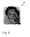
- FIG. 2shows a target image 10 'which is deformed in relation to the source image 10 and has been transformed by a method according to the prior art by providing the source image 10 with a mesh or grid of polygons, not shown separately here, and combining the grid is deformed with the associated image pixels. Due to the large number of vectors required for this, these conventional methods require a large storage space and are therefore very computationally intensive. In addition, the target image 10 'formed as a result has polygonal structures due to the polygon deformation.
- the method according to the inventionstarts by defining a deformation or distortion direction by a single deformation vector 11 shown in FIG. 3 during an initialization phase in a source image 10 identified by a pixel matrix is determined, and this deformation vector 11 by a starting point 11 'with the starting point coordinates (x 0 , y 0 ) and an end point 11''with the end point coordinates (x 1 , y 1 ) is set and both the starting point 11' and the end point 11 "lie within the pixel matrix of the source image 10.
- This initialization phaseis illustrated on the illustrated in Fig. 1 as grayscale photograph formed source image 10 with a projection of a deformation vector 11.
- FIG. 4shows a basic flow diagram 20 of the method according to the invention, wherein the pixel matrix of the source image 10 and the coordinates of the starting point 11 'and the end point 11 "of the deformation vector 11 are input as input variables 21, while the output image 22 is the pixel matrix of the target image Transformation equation 23 is determined.
- the right-hand side of the transformation equationhas as input variables 21 the respective pixels (x Q , y Q ) of the matrix of the source image 10 as well as the difference between the coordinates of the initial and End point (x 0 , y 0 ) or (x 1 , y 1 ) defined deformation vector 11 (x 1 - x 0 , y 1 - y 0 ) and a scaling factor F (x, y, K), while the left Side of the transformation equation as output variables 22 reproduces the respectively assigned pixels (x z , y z ) of the matrix of the target image; the scaling factor is in each case taken as the main diagonal element of a (2x2) matrix whose extradiagonal elements each have the zero, the product of the (2x2) matrix and the deformation vector 11 added to the coordinates of the respective source image pixel (x Q , y Q ) in each case corresponding target image pixels (x z , y z ) results.
- the scaling factoris in each case taken as the main
- the respective pixels of the source image 10are shifted in the direction of the deformation vector 11 determined by the start point 11 'and the end point 11 "in accordance with their respective distances to the start and end points 11', 11".
- the degree of displacement or distortiondepends on the scaling factor F (x, y, K) listed in the transformation equation, which essentially consists of the sum of the distances of the respective pixels to the start and end points 11 ', 11' 'in relation to Length of the deformation vector 11 is determined so that pixels in the immediate vicinity of the vector 11, ie to the start and end points, are subject to a greater shift than those pixels arranged at greater distances thereto, while pixels very far away from the deformation vector 11 remain virtually unshifted.
- FIG. 6illustrates, in a contour line diagram 40, the functional profile of the scaling factor 31. From this diagram 40 it can be seen from a plurality of elliptically running height or equipotential lines 42, 42 ', 42 "that the scaling factor function 31 has an elliptical cross section.
- the foci 43, 43 'of such an ellipsecoincide respectively with the beginning and end points 11' and 11 "of the deformation vector 11 together. Pixels lying on such an ellipse with starting point 11 'and end point 11 "of the deformation vector 11 as foci 43, 43' are shifted evenly.
- gaps resulting from the transformationare filled out. These gaps are regions in the target image 10 "in which no pixels or only very few pixels of the source image 10 have been imaged, so that these regions in the target image 10" have no correspondence in the source image 10. These regions of the target image 10 "are filled with newly generated pixels in this process step by determining transformed pixels arranged adjacent to these empty regions and determining, from their respectively assigned color density values for the newly generated pixels, the respectively corresponding color density values by interpolation be stored.
- Fig. 8shows the target image 10 "in which this interpolation was performed; Due to the above-described properties of the scale factor function, the target image 10 "has round structures in the deformed regions, so that the process is advantageously suitable for representing natural shapes.
Landscapes
- Physics & Mathematics (AREA)
- General Physics & Mathematics (AREA)
- Engineering & Computer Science (AREA)
- Theoretical Computer Science (AREA)
- Image Processing (AREA)
Abstract
Description
Translated fromGermanDie Erfindung betrifft ein Bildverarbeitungsverfahren zur optischen Anzeige von Informationen und/oder Signalen, wobei ein Quellbild in ein demgegenüber deformiertes Zielbild transformiert wird.The invention relates to an image processing method for the optical display of information and / or signals, wherein a source image is transformed into a contrast deformed target image.
Derartige Verfahren, wie z.B. in GB-A-2 312 123 beschrieben, sind unter dem Begriff "Warping"-Algorithmen bekannt und werden zur Deformation von Bildern eingesetzt. Dabei wird üblicherweise als "Warping"-Maske ein Polygonnetz zugrundegelegt. Da es dazu der Bereitstellung von Vektorscharen bedarf, handelt es sich dabei um komplizierte Techniken, die naturgemäß einen großen Speicherplatzbedarf haben und somit auch rechenintensiv sind. Dadurch sind die herkömmlichen Verfahren nach dem Stande der Technik praktisch nur in größeren Rechenanlagen, sog. "Workstations" oder dergleichen, nutzbar.Such methods, e.g. in GB-A-2 312 123 are known by the term "warping" algorithms and are used to deform images. It is usually based on a "mesh" as a "warping" mask. Since this requires the provision of vector crowds, these are complicated techniques that naturally have a large storage space requirement and are thus computationally intensive. As a result, the conventional methods according to the state of the art can be used practically only in larger computer systems, so-called "workstations" or the like.
Der Erfindung liegt demgegenüber die Aufgabe zugrunde, ein Bildverarbeitungsverfahren der eingangs genannten Art zu schaffen, das gegenüber dem Stand der Technik einen geringeren Speicherplatzbedarf aufweist und damit auch in Mikroprozessor-gestützten Kleingeräten mit relativ kleinen Datenspeichermodulen, wie dies beispielsweise bei Mobiltelefonen der dergleichen der Fall ist, einsetzbar ist.The invention is the object of the invention to provide an image processing method of the type mentioned above, which has a lower storage space requirement compared to the prior art and thus in microprocessor-based small devices with relatively small data storage modules, as is the case for example in mobile phones the like , is usable.
Die Aufgabe wird in verfahrenstechnischer Hinsicht dadurch gelöst, daß in einer Initialisierungsphase innerhalb des Quellbildes ein eine Deformationsrichtung bestimmender Deformationsvektor definiert wird und daß für die jeweiligen Bildpixel des Quellbildes nach Maßgabe einer von diesem Vektor und eines die Lage der jeweiligen Bildpixel in Relation zu diesem Vektor berücksichtigenden Skalierungsfaktors funktional abhängigen Transformationsvorschrift jeweils eine korrespondierende Koordinatenposition in dem Zielbild ermittelt wird.The object is achieved in procedural terms, characterized in that in a initialization phase within the source image, a deformation direction defining deformation vector is defined and that for the respective image pixels of the source image are determined in each case a corresponding coordinate position in the target image in accordance with a transformation rule functionally dependent on this vector and a scaling factor that takes into account the position of the respective image pixels in relation to this vector.
Während herkömmliche Verfahren aufgrund der Bereitstellung von Vektorfeldern besonders speicherplatz- und rechenintensiv sind und demgemäß praktisch nur auf größeren Computern ("Workstations") einsetzbar sind und zufriedenstellende Resultate erzielen, benötigt demgegenüber das erfindungsgemäße Verfahren relativ wenig Speicherplatz aufgrund eines einzigen die Deformationsrichtung festlegenden Vektors und ist somit auch für relativ kleine Speichermodule, wie sie typischerweise in Mobiltelefonen eingesetzt werden, geeignet.While conventional methods due to the provision of vector fields are particularly memory space and computationally intensive and thus practically only on larger computers ("workstations") can be used and achieve satisfactory results, on the other hand requires the inventive method relatively little storage space due to a single vector defining the direction of deformation and is thus also for relatively small memory modules, as they are typically used in mobile phones suitable.
Eine bevorzugte Ausführungsform des erfindungsgemäßen Bildverarbeitungsverfahrens besteht darin, daß dem Skalierungsfaktor ein im wesentlichen elliptischer Funktionsverlauf derart zugeordnet wird, daß sich der Deformationsvektor ungefähr zwischen den Brennpunkten des elliptischen Funktionsverlaufs erstreckt. Im Gegensatz zum Stand der Technik, mit dessen Polygonmethode eckige Konturen im Zielbild entstehen, werden gemäß der Erfindung demgegenüber runde Strukturen im Zielbild erzielt, so daß sich das erfindungsgemäße Verfahren besonders für Quellbilder eignet, die natürliche Formen, wie beispielsweise Gesichter, Körper oder dergleichen, aufweisen.A preferred embodiment of the image processing method according to the invention is that the scaling factor is assigned a substantially elliptical function course such that the deformation vector extends approximately between the focal points of the elliptical function curve. In contrast to the prior art, with the polygon method angular contours arise in the target image, according to the invention in contrast round structures are achieved in the target image, so that the inventive method is particularly suitable for source images, the natural forms, such as faces, body or the like, exhibit.
Ferner wird für jedes Bildpixel des Quellbildes der jeweils zugeordnete Wert des Skalierungsfaktors ermittelt, wobei der Skalierungsfaktor im wesentlichen einerseits von der aus dem Abstand A0 des jeweiligen Bildpixels (x, y) von dem Anfangspunkt (x0, y0) des Deformationsvektors und dem Abstand A1 des jeweiligen Bildpixels von dem Endpunkt (x1, y1) des Deformationsvektors gebildeten Summe S= A0 + A1 und andererseits von der Länge L des Deformationsvektors abhängig ist. Zur Realisierung des elliptischen Funktionsverlaufs des Skalierungsfaktors wird nach einer vorteilhaften Weiterbildung des erfindungsgemäßen Bildverarbeitungsverfahrens für jedes Bildpixel des Quellbildes der jeweils zugeordnete Wert des Skalierungsfaktors gemäß 1-((S-αL)/(αL)) ermittelt, wobei α eine justierbare Konstante ist, und falls der jeweils ermittelte Wert größer als Null ist, dieser positive Wert dem jeweiligen Bildpixel zugewiesen wird, während andernfalls für dieses Bildpixel der Wert des Skalierungsfaktors auf Null gesetzt wird. Um ein Quellbild in ein demgegenüber deformiertes Zielbild zu transformieren, werden mit dem jeweiligen Wert des Skalierungsfaktors die jeweiligen Bildpixel des Zielbildes aus der koordinatenweisen Summenbildung der jeweils dazu korrespondierenden Bildpixel des Quellbildes mit dem koordinatenweise gebildeten Produkt des jeweils ermittelten Skalierungsfaktors mit dem Deformationsvektor ermittelt.Furthermore, the respectively assigned value of the scaling factor is determined for each image pixel of the source image, wherein the scaling factor essentially depends on the one from the distance A0 of the respective image pixel (x, y) from the starting point (x0 , y0 ) of the deformation vector and the Distance A1 of the respective image pixel from the end point (x1 , y1 ) of the deformation vector formed sum S = A0 + A1 and on the other hand depends on the length L of the deformation vector. In order to realize the elliptical function curve of the scaling factor, according to an advantageous further development of the image processing method according to the invention, the respective assigned value of the scaling factor is determined according to 1 - ((S-αL) / (αL)), where α is an adjustable constant, and if the respective determined value is greater than zero, this positive value is assigned to the respective image pixel, while otherwise for this image pixel the value of the scaling factor is set to zero. To transform a source image into a contrast deformed target image, the respective image pixel of the target image from the coordinate sum of the corresponding image pixels of the source image with the coordinate formed product of each determined scaling factor with the deformation vector is determined with the respective value of the scaling factor.
In einem daran anschließenden Verfahrensschritt werden in dem Zielbild aufgrund der Transformation auftretende Leerstellen mit neu generierten Bildpixeln aufgefüllt, indem aus den jeweiligen Farbdichtewerten von benachbart angeordneten Bildpixeln entsprechende Farbdichtewerte für die neu generierten Bildpixel interpoliert werden. Durch das Auffüllen von derart leeren Bereichen mit entsprechend aus den angrenzend dazu abgebildeten Bildpixeln gewinnt das Zielbild an Schärfe im Vergleich zu herkömmlichen Verfahren, bei denen derartige Bereiche mit Bildpixeln von einheitlichem Farbdichtewert aufgefüllt werden.In a subsequent method step, vacancies occurring in the target image due to the transformation are filled with newly generated image pixels by corresponding color density values from the respective color density values of adjacently arranged image pixels be interpolated for the newly generated image pixels. By filling such vacant areas with image pixels correspondingly imaged therefrom, the target image acquires sharpness as compared to conventional methods in which such areas are filled with image pixels of uniform color density value.
Weitere vorteilhafte Ausgestaltungen des erfindungsgemäßen Bildverarbeitungsverfahrens lassen sich den Unteransprüchen entnehmen.Further advantageous embodiments of the image processing method according to the invention can be taken from the subclaims.
In vorrichtungstechnischer Hinsicht wird die oben angegebene Aufgabe bei einer Vorrichtung zur Durchführung des Bildverarbeitungsverfahrens dadurch gelöst, daß innerhalb des Quellbildes ein eine Deformationsrichtung bestimmender Deformationsvektor definierbar ist und daß für die jeweiligen Bildpixel des Quellbildes nach Maßgabe einer von dem Deformationsvektor und einem die Lage der jeweiligen Bildpixel in Relation zu diesem Deformationsvektor berücksichtigenden Skalierungsfaktor funktional abhängigen Transformationsvorschrift jeweils eine korrespondierende Koordinatenposition in dem Zielbild ermittelbar ist. Dabei weist der Skalierungsfaktor einen im wesentlichen elliptischen Funktionsverlauf auf, wobei sich der Deformationsvektor ungefähr zwischen den Brennpunkten des elliptischen Funktionsverlaufs erstreckt. Indem zur Definition einer Deformation lediglich ein einzelner Vektor erforderlich ist, hat die erfindungsgemäße Vorrichtung einen relativ geringen Speicherplatzbedarf und läßt sich demgemäß vorteilhaft in Mikrocomputer-gestützten portablen bzw. mobilen Kleingeräten mit naturgemäß knappen Speicherplatzressourcen, jedoch auch eigenständig einsetzen.In device-technical terms, the above object is achieved in a device for carrying out the image processing method in that within the source image, a deformation direction determining deformation vector is definable and that for the respective image pixels of the source image in accordance with one of the deformation vector and the position of the respective image pixels a corresponding coordinate position in the target image can be determined in each case in relation to the scaling factor that takes into account the function of this deformation-vector-dependent transformation rule. In this case, the scaling factor has a substantially elliptical function profile, wherein the deformation vector extends approximately between the focal points of the elliptical function profile. By only a single vector is required to define a deformation, the device according to the invention has a relatively small storage space requirement and can therefore be advantageous in microcomputer-based portable or mobile small devices with naturally scarce storage space resources, but also use independently.
Anhand der beigefügten Zeichnung soll nachstehend eine Ausführungsform des erfindungsgemäßen Verfahrens näher erläutert werden. In teilweise schematischen Ansichten zeigen:
- Fig. 1 ein als Graustufenfotographie ausgebildetes Quellbild,
- Fig. 2 ein aus dem Quellbild von Fig. 1 gemäß dem Stand der Technik gebildetes Zielbild,
- Fig. 3 eine vereinfachte Darstellung eines innerhalb einer Quellbild-Pixelmatrix anhand seines Anfangs- und Endpunktes definierten Deformationsvektors gemäß einer Initialisierungsphase des erfindungsgemäßen Verfahrens,
- Fig. 4 ein Eingabe/Ausgabe-Ablaufschema des erfindungsgemäßen Verfahrens, wobei als Eingabegrößen des Verfahrens die Quellbildpixelmatrix und die Koordinaten des Deformationsvektors eingespeist werden und als Ausgabegröße eine Zielbildpixelmatrix ermittelt wird,
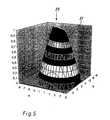
- Fig. 5 eine perspektivische Darstellung des Funktionsverlaufs eines Ausführungsbeispiels des zum erfindungsgemäßen Verfahrens gehörenden Skalierungsfaktors,
- Fig. 6 ein Höhenliniendiagramm des Funktionsverlaufs des Skalierungsfaktors von Fig. 5,
- Fig. 7 ein aus dem Quellbild von Fig. 1 gemäß dem erfindungsgemäßen Verfahren gebildetes Zielbild vor einem abschließenden Interpolationsschritt, wobei ungefähr kreisförmig angeordnete Strukturaufhellungen Fehlstellen im Zielbild darstellen, sowie
- Fig. 8 das Zielbild von Fig. 7 mit nach dem erfindungsgemäßen Verfahren durchgeführter Interpolation, durch welche aufgrund der Transformation entstandene Fehlstellen aufgefüllt wurden.
- 1 is a trained as Graustufenfotographie source image,
- FIG. 2 is a target image formed from the source image of FIG. 1 according to the prior art; FIG.
- 3 shows a simplified representation of a deformation vector defined within a source image pixel matrix on the basis of its start and end point according to an initialization phase of the method according to the invention,
- 4 shows an input / output flowchart of the method according to the invention, in which the source image pixel matrix and the coordinates of the deformation vector are input as input variables of the method and an output image pixel matrix is determined as the output variable,
- 5 is a perspective view of the functional course of an embodiment of the scaling factor associated with the method according to the invention,
- 6 is a contour plot of the function curve of the scaling factor of FIG. 5;
- FIG. 7 shows a target image formed from the source image of FIG. 1 according to the method according to the invention final interpolation step, wherein approximately circularly arranged structure brightening represent defects in the target image, as well as
- 8 shows the target image from FIG. 7 with interpolation carried out according to the method according to the invention, through which defects due to the transformation have been filled up.
Das erfindungsgemäße Verfahren dient der deformierenden Bildverarbeitung eines aus Informationssignalen zusammengesetzten Ursprungs- oder Quellbildes, welches in ein demgegenüber deformiertes Zielbild transformiert wird.The method according to the invention serves for the deforming image processing of an origin or source image composed of information signals, which is transformed into a contrastly deformed target image.
Fig. 1 zeigt ein Beispiel eines mit 10 bezeichneten Quellbildes. Demgegenüber zeigt Fig. 2 ein gegenüber dem Quellbild 10 deformiertes Zielbild 10', das nach einem Verfahren gemäß dem Stand der Technik transformiert wurde, indem das Quellbild 10 mit einem - hier nicht gesondert dargestellten - Netz oder Gitter von Polygonen versehen wird und das Gitter zusammen mit den zugeordneten Bildpixeln deformiert wird. Aufgrund der Vielzahl von dafür erforderlichen Vektoren haben diese herkömmlichen Verfahren einen hohen Speicherplatzbedarf und sind demgemäß sehr rechenintensiv. Zudem weist das dadurch gebildete Zielbild 10' aufgrund der Polygon-Deformation insgesamt kantige Strukturen auf.FIG. 1 shows an example of a source image labeled 10. In contrast, FIG. 2 shows a target image 10 'which is deformed in relation to the
Hier setzt nun das erfindungsgemäße Verfahren an, indem während einer Initialisierungsphase in einem durch eine Pixelmatrix gekennzeichneten Quellbild 10 eine Deformations - bzw. Verzerrungsrichtung durch einen einzigen - in Fig. 3 dargestellten - Deformationsvektor 11 definiert bzw. festgelegt wird, wobei dieser Deformationsvektor 11 durch einen Anfangspunkt 11' mit den Anfangspunktkoordinaten (x0, y0) und einen Endpunkt 11'' mit den Endpunktkoordinaten (x1, y1) festgelegt wird und sowohl der Anfangspunkt 11' als auch der Endpunkt 11'' innerhalb der Pixelmatrix des Quellbildes 10 liegen. Diese Initialisierungsphase ist an dem in Fig. 1 dargestellten als Graustufenfotographie ausgebildeten Quellbild 10 mit einer Projektion eines Deformationsvektors 11 veranschaulicht.This is where the method according to the invention starts by defining a deformation or distortion direction by a
Fig. 4 zeigt ein prinzipielles Ablaufschema 20 des erfindungsgemäßen Verfahrens, wobei als Eingangsgrößen 21 die Pixelmatrix des Quellbildes 10 sowie die Koordinaten des Anfangspunktes 11' und des Endpunktes 11'' des Deformationsvektors 11 eingegeben werden, während als Ausgangsgröße 22 die Pixelmatrix des Zielbildes anhand einer Transformationsgleichung 23 ermittelt wird.4 shows a basic flow diagram 20 of the method according to the invention, wherein the pixel matrix of the
In diesem Verfahrensschritt wird für jedes Pixel (xQ, yQ) aus der Pixelmatrix des Quellbildes 10 jeweils eine Koordinatenposition (xz , yz) in der Pixelmatrix des Zielbildes ermittelt, wobei diesem Verfahrensschritt die nachstehende Transformationsgleichung in Matrizenform zugrundegelegt wird:
Dabei weist die rechte Seite der Transformationsgleichung als Eingangsgrößen 21 die jeweiligen Pixel (xQ, yQ) der Matrix des Quellbildes 10 sowie den durch die Differenz zwischen den Koordinaten des Anfangs- und des Endpunktes (x0, y0) bzw. (x1, y1) definierten Deformationsvektor 11 (x1 - x0, y1 - y0) und einen Skalierungsfaktor F(x,y,K) auf, während demgegenüber die linke Seite der Transformationsgleichung als Ausgangsgrößen 22 die jeweils zugeordneten Pixel (xz, yz) der Matrix des Zielbildes wiedergibt; der Skalierungsfaktor ist jeweils als Hauptdiagonalelement einer (2x2)-Matrix aufgenommen, deren Außerdiagonalelemente jeweils die Null aufweisen, wobei das Produkt aus der (2x2)-Matrix und dem Deformationsvektor 11 addiert mit den Koordinaten des jeweiligen Quellbildpixels (xQ, yQ) das jeweils dazu korrespondierende Zielbildpixel (xz, yz) ergibt. Der in der Transformationsgleichung aufgenommene Skalierungsfaktor F(x,y,K) ist funktional abhängig vom relativen Abstand des jeweiligen Pixels (x, y) des Quellbildes bezüglich des Anfangspunktes (x0, y0) und des Endpunktes (x1, y1) des Deformationsvektors 11 sowie einer Größe K:
Nimmt dieser Ausdruck für ein jeweils eingegebenes Pixel (x, y) des Quellbildes 10 einen Wert F>0 ein, so wird dieser positive Wert diesem Pixel zugeordnet und abgespeichert, während andernfalls dieser Wert auf F=0 gesetzt wird. Dabei ist die Größe K einerseits von der Länge des Deformationsvektors 11 und andererseits von einer justierbaren Konstante α abhängig, wobei für K folgende Beziehung gilt:
Somit werden bei der Transformation die jeweiligen Pixel des Quellbildes 10 nach Maßgabe von deren jeweiligen Abständen zu Anfangs- und Endpunkt 11', 11'' in Richtung des durch den Anfangspunkt 11' und den Endpunkt 11'' bestimmten Deformationsvektors 11 verschoben. Der Grad der Verschiebung bzw. Verzerrung ist abhängig von dem in der Transformationsgleichung aufgeführten Skalierungsfaktor F(x,y,K), welcher im wesentlichen aus der Summe der Abstände der jeweiligen Pixel zu Anfangs- und Endpunkt 11', 11'' in Relation zur Länge des Deformationsvektors 11 ermittelt wird, so daß Pixel, die in unmittelbarer Nähe zum Vektor 11, d.h. zum Anfangs- und Endpunkt, angeordnet sind, eine stärkere Verschiebung erfahren als solche Pixel, die in größeren Abständen dazu angeordnet sind, während Pixel mit sehr großem Abstand zum Deformationsvektor 11 praktisch unverschoben bleiben.Thus, in the transformation, the respective pixels of the
Fig. 5 veranschaulicht in einer perspektivischen Darstellung 30 den graphischen Funktionsverlauf des Skalierungsfaktors 31, wobei im Ausführungsbeispiel für die Parameter α und K die Werte α=1 bzw. K=8.6023 gewählt wurden und der Deformationsvektor mit seinen Anfangspunktkoordinaten (-2, -2) und seinen Endpunktkoordinaten (3, 5) definiert ist.5 shows in a perspective view 30 the graphical function curve of the
Fig. 6 veranschaulicht in einem Höhenliniendiagramm 40 den Funktionsverlauf des Skalierungsfaktors 31. Aus diesem Diagramm 40 ist anhand mehrerer elliptisch verlaufender Höhen- oder Äquipotentiallinien 42, 42', 42'' ersichtlich, daß die Skalierungsfaktorfunktion 31 einen elliptischen Querschnitt aufweist. Die Brennpunkte 43, 43' einer derartigen Ellipse fallen jeweils mit dem Anfangs- und Endpunkt 11' bzw. 11'' des Deformationsvektors 11 zusammen. Pixel, die auf einer derartigen Ellipse mit Anfangspunkt 11' und Endpunkt 11'' des Deformationsvektors 11 als Brennpunkte 43, 43' liegen, werden gleichmäßig verschoben.FIG. 6 illustrates, in a contour line diagram 40, the functional profile of the
In einem weiteren Verfahrensschritt werden in der Zielabbildung, d.h. in der Pixelmatrix des Zielbildes 10'', aufgrund der Transformation entstehende Lücken, die in Fig. 7 durch kreisförmige Strukturaufhellungen 44 ersichtlich sind, ausgefüllt. Bei diesen Lücken handelt es sich um Bereiche im Zielbild 10'', in welche keine Pixel oder nur sehr wenige Pixel des Quellbildes 10 abgebildet wurden, so daß diese Bereiche im Zielbild 10'' keine Korrespondenz im Quellbild 10 aufweisen. Diese Bereiche des Zielbildes 10'' werden in diesem Verfahrensschritt mit neu generierten Pixeln aufgefüllt, indem angrenzend zu diesen leeren Bereichen angeordnete transformierte Pixel ermittelt werden und aus deren jeweils zugeordneten Farbdichtewerten für die neu zu generierenden Pixel die jeweils korrespondierenden Farbdichtewerte durch Interpolation ermittelt, zugeordnet und abgespeichert werden. Fig. 8 zeigt das Zielbild 10'', bei dem diese Interpolation durchgeführt wurde; aufgrund der vorstehend erläuterten Eigenschaften der Skalierungsfaktorfunktion weist das Zielbild 10'' runde Strukturen in den deformierten Bereichen auf, so daß sich das Verfahren vorteilhaft zur Darstellung natürlicher Formen eignet.In a further process step, in the target image, i. in the pixel matrix of the
Claims (10)
- Image processing method for visually displaying information and/or signals, a source image being transformed into a distorted or warped target image relative to said source image,characterised in that a deformation vector (11) which determines a deformation direction is defined within the source image (10) and a corresponding coordinate position is determined in the target image (10'') for each pixel of the source image (10) according to a transformation rule (23) that is functionally dependent on said deformation vector (11) and on a scaling factor (31) that takes account of the position of each pixel in relation to the deformation vector (11).
- Image processing method according to claim 1,characterised in that an essentially elliptical function curve is assigned to the scaling factor (31) in such a way that the deformation vector (11) extends approximately between the foci (43, 43') of the elliptical function curve.
- Image processing method according to claim 1 or 2,characterised in that the assigned scaling factor value (31) is determined for each source image pixel (10), said scaling factor (31) being essentially dependent, on the one hand, on the sum S= A0 + A1 of the distance A0 of the relevant image pixel (x, y) from the starting point (11'), designated by the coordinates (x0, y0), of the deformation vector (11) and the distance A1 of the relevant image pixel from the end point (11''), designated by the coordinates (x1, y1), of the deformation vector and, on the other hand, on the length L of the deformation vector (11).
- Image processing method according to claim 3,characterised in that the assigned value of the scaling factor (31) is determined according to 1-((S-αL)/(αL)) for each pixel of the source image (10), α being an adjustable constant, and if the value determined in each case is greater than zero, this positive value is assigned to the relevant pixel, whereas, if not, the value of the scaling factor (31) is set to zero for this pixel.
- Image processing method according to one of claims 2 to 4,characterised in that the relevant pixels of the target image (10'') are determined from coordinate summation of the corresponding pixels of the source image (10) with the coordinate-formed product of the scaling factor (31) determined in each case and the deformation vector (11).
- Image processing method according to one of claims 2 to 5,characterised in that the relations A0 = ((x-x0)2 + (y-Y0)2)1/2 and A1 = ((x-x1)2 + (y-y1)2)1/2 are respectively defined as the distance A0 of the relevant image pixel (x, y) from the starting point (11'), designated by the coordinates (x0, y0), of the deformation vector (11) and as the distance A1 of the relevant pixel from its end point (11) designated by the coordinates (x1, y1).
- Image processing method according to one of claims 1 to 6,characterised in that the length of the deformation vector (11) is calculated according to the relation L = ((x1-x0)2 + (y1-y0)2)1/2.
- Method according to one of claims 1 to 7,characterised in that voids occurring in the target image (10'') because of the transformation are filled in with newly generated pixels by interpolating corresponding colour density values for the newly generated pixels from the relevant colour density values of adjacently disposed pixels.
- Arrangement for performing the image processing method, in particular according to one of claims 1 to 8,characterised in that a deformation vector (11) which determines a deformation direction can be defined within the source image (10) and a corresponding coordinate position can be determined in the target image (10'') for each pixel of the source image (10) according to a transformation rule (23) that is functionally dependent on said deformation vector (11) and on a scaling factor (31) that takes account of the position of each pixel in relation to the deformation vector (11).
- Arrangement according to claim 9,characterised in that the scaling factor (31) has an essentially elliptical function curve, the deformation vector (11) extending approximately between the foci (43, 43') of the elliptical function curve.
Applications Claiming Priority (3)
| Application Number | Priority Date | Filing Date | Title |
|---|---|---|---|
| DE10120286 | 2001-04-25 | ||
| DE10120286 | 2001-04-25 | ||
| PCT/DE2002/001276WO2002089059A2 (en) | 2001-04-25 | 2002-04-08 | Image processing method |
Publications (2)
| Publication Number | Publication Date |
|---|---|
| EP1386287A2 EP1386287A2 (en) | 2004-02-04 |
| EP1386287B1true EP1386287B1 (en) | 2007-03-07 |
Family
ID=7682686
Family Applications (1)
| Application Number | Title | Priority Date | Filing Date |
|---|---|---|---|
| EP02740241AExpired - LifetimeEP1386287B1 (en) | 2001-04-25 | 2002-04-08 | Image processing method |
Country Status (4)
| Country | Link |
|---|---|
| US (1) | US20040156556A1 (en) |
| EP (1) | EP1386287B1 (en) |
| DE (1) | DE50209661D1 (en) |
| WO (1) | WO2002089059A2 (en) |
Families Citing this family (12)
| Publication number | Priority date | Publication date | Assignee | Title |
|---|---|---|---|---|
| US6765589B1 (en) | 2000-11-16 | 2004-07-20 | Adobe Systems Incorporated | Brush for warping and water reflection effects |
| US7312805B1 (en) | 2003-09-29 | 2007-12-25 | Adobe Systems Incorporated | User defined warping tool |
| GB2438668B (en)* | 2006-06-02 | 2008-07-30 | Siemens Molecular Imaging Ltd | Deformation of mask-based images |
| US7843467B2 (en)* | 2006-12-18 | 2010-11-30 | Microsoft Corporation | Shape deformation |
| GB2448168B (en)* | 2007-04-04 | 2009-08-26 | Siemens Medical Solutions | Method for interactive manual deformable registration |
| US8718133B2 (en)* | 2008-03-26 | 2014-05-06 | Samsung Electronics Co., Ltd. | Method and system for image scaling detection |
| US8165425B2 (en)* | 2008-07-24 | 2012-04-24 | Siemens Medical Solutions Usa, Inc. | Interactive manual deformable registration of images |
| US20140267425A1 (en)* | 2013-03-15 | 2014-09-18 | Crayola Llc | Personalized Digital Animation Kit |
| US9946448B2 (en) | 2013-03-15 | 2018-04-17 | Crayola Llc | Coloring kit for capturing and animating two-dimensional colored creation |
| US10475226B2 (en) | 2013-03-15 | 2019-11-12 | Crayola Llc | Coloring kit for capturing and animating two-dimensional colored creation |
| US10403029B2 (en)* | 2017-05-03 | 2019-09-03 | Microsoft Technology Licensing, Llc | Methods and systems for multistage post-rendering image transformation |
| EP3824432B1 (en)* | 2018-11-09 | 2025-05-07 | Samsung Electronics Co., Ltd. | Image resynthesis using forward warping, gap discriminators, and coordinate-based inpainting |
Family Cites Families (11)
| Publication number | Priority date | Publication date | Assignee | Title |
|---|---|---|---|---|
| DE69332042T2 (en)* | 1992-12-18 | 2003-01-02 | Koninklijke Philips Electronics N.V., Eindhoven | Delayed positioning of relatively elastically deformed spatial images by matching surfaces |
| US5636338A (en)* | 1993-01-29 | 1997-06-03 | Silicon Graphics, Inc. | Method for designing curved shapes for use by a computer |
| DE4316847A1 (en)* | 1993-05-19 | 1994-11-24 | Philips Patentverwaltung | Method for equalizing x-rays and arrangement for carrying out the method |
| WO1995006297A1 (en)* | 1993-08-27 | 1995-03-02 | Massachusetts Institute Of Technology | Example-based image analysis and synthesis using pixelwise correspondence |
| US5613013A (en)* | 1994-05-13 | 1997-03-18 | Reticula Corporation | Glass patterns in image alignment and analysis |
| US6288814B1 (en)* | 1994-05-19 | 2001-09-11 | Ortel Corporation | In-line predistorter for linearization of electronic and optical signals |
| DE4435183C2 (en)* | 1994-09-30 | 2000-04-20 | Siemens Ag | Method for operating a magnetic resonance device |
| US5731819A (en)* | 1995-07-18 | 1998-03-24 | Softimage | Deformation of a graphic object to emphasize effects of motion |
| GB2312123B (en)* | 1996-04-12 | 1999-01-13 | Discreet Logic Inc | Relocating picture points in response to manual operation of an interface device |
| US6807290B2 (en)* | 2000-03-09 | 2004-10-19 | Microsoft Corporation | Rapid computer modeling of faces for animation |
| US6963667B2 (en)* | 2001-01-12 | 2005-11-08 | National Instruments Corporation | System and method for signal matching and characterization |
- 2002
- 2002-04-08EPEP02740241Apatent/EP1386287B1/ennot_activeExpired - Lifetime
- 2002-04-08USUS10/476,067patent/US20040156556A1/ennot_activeAbandoned
- 2002-04-08DEDE50209661Tpatent/DE50209661D1/ennot_activeExpired - Fee Related
- 2002-04-08WOPCT/DE2002/001276patent/WO2002089059A2/enactiveIP Right Grant
Also Published As
| Publication number | Publication date |
|---|---|
| WO2002089059A3 (en) | 2003-05-30 |
| WO2002089059A2 (en) | 2002-11-07 |
| DE50209661D1 (en) | 2007-04-19 |
| EP1386287A2 (en) | 2004-02-04 |
| US20040156556A1 (en) | 2004-08-12 |
Similar Documents
| Publication | Publication Date | Title |
|---|---|---|
| DE60020887T2 (en) | OPTICAL FLOW AND PICTURE CONSTRUCTION | |
| DE69430336T2 (en) | Enlargement of digital images using edge mapping | |
| DE69623642T2 (en) | VECTOR CORRELATION SYSTEM FOR AUTOMATICALLY FINDING PATTERNS IN AN IMAGE | |
| EP1386287B1 (en) | Image processing method | |
| DE69323983T2 (en) | Method for modifying the bold letters | |
| DE3852596T2 (en) | Method for generating a discrete network for simulation using finite differences. | |
| DE60000678T2 (en) | Optical scanner and related software | |
| DE3315148C2 (en) | ||
| DE102004004641A1 (en) | Image processing method, involves determining contribution of each voxel to bin of detector array or vice versa in accordance with projections of voxel edges and detector bin edges on predetermined plane | |
| EP3427224B1 (en) | Method, head-up display and output system for the perspective transformation and outputting of image content, and vehicle | |
| DE69029429T2 (en) | Binary image reduction process | |
| DE69529732T2 (en) | Correction of the perspective of textures in graphic images by adaptive approximation | |
| DE69813931T2 (en) | Filtering method for focusing images | |
| EP2893510B1 (en) | Method and image processing apparatus for removing a visual object from an image | |
| DE102005046772A1 (en) | Iterative method for interpolation of image information values | |
| DE69814011T2 (en) | COMPUTER GRAPHIC METHOD AND DEVICE | |
| DE3837068B4 (en) | Image processing method for obtaining a silhouette | |
| EP1141883B1 (en) | Method for comparing point sets | |
| EP2187354B1 (en) | Method for representing graphical symbols | |
| EP3465608B1 (en) | Method and device for determining a transfer between two display images, and vehicle | |
| EP1537538B1 (en) | Method for determination of weighting factors for the colour calculation of a colour value for texels in a footprint | |
| DE10242639A1 (en) | Method for analysis and modification of footprint i.e. perspective projection of pixel e.g. for computerized raster image displays, requires initially establishing resolution of textured elements associated with footprint | |
| DE69325739T2 (en) | Graphic system using quadratic polynomial elements | |
| DE19703004A1 (en) | Method for mapping a source pixel image onto a target pixel space | |
| DE102008048257B4 (en) | Method for detecting a block raster |
Legal Events
| Date | Code | Title | Description |
|---|---|---|---|
| PUAI | Public reference made under article 153(3) epc to a published international application that has entered the european phase | Free format text:ORIGINAL CODE: 0009012 | |
| 17P | Request for examination filed | Effective date:20031007 | |
| AK | Designated contracting states | Kind code of ref document:A2 Designated state(s):AT BE CH CY DE DK ES FI FR GB GR IE IT LI LU MC NL PT SE TR | |
| AX | Request for extension of the european patent | Extension state:AL LT LV MK RO SI | |
| GRAP | Despatch of communication of intention to grant a patent | Free format text:ORIGINAL CODE: EPIDOSNIGR1 | |
| GRAS | Grant fee paid | Free format text:ORIGINAL CODE: EPIDOSNIGR3 | |
| GRAA | (expected) grant | Free format text:ORIGINAL CODE: 0009210 | |
| AK | Designated contracting states | Kind code of ref document:B1 Designated state(s):DE FI GB | |
| REG | Reference to a national code | Ref country code:GB Ref legal event code:FG4D Free format text:NOT ENGLISH | |
| PGFP | Annual fee paid to national office [announced via postgrant information from national office to epo] | Ref country code:FI Payment date:20070313 Year of fee payment:6 | |
| GBT | Gb: translation of ep patent filed (gb section 77(6)(a)/1977) | Effective date:20070307 | |
| REF | Corresponds to: | Ref document number:50209661 Country of ref document:DE Date of ref document:20070419 Kind code of ref document:P | |
| PGFP | Annual fee paid to national office [announced via postgrant information from national office to epo] | Ref country code:GB Payment date:20070416 Year of fee payment:6 | |
| PLBE | No opposition filed within time limit | Free format text:ORIGINAL CODE: 0009261 | |
| STAA | Information on the status of an ep patent application or granted ep patent | Free format text:STATUS: NO OPPOSITION FILED WITHIN TIME LIMIT | |
| PG25 | Lapsed in a contracting state [announced via postgrant information from national office to epo] | Ref country code:DE Free format text:LAPSE BECAUSE OF NON-PAYMENT OF DUE FEES Effective date:20071101 | |
| 26N | No opposition filed | Effective date:20071210 | |
| GBPC | Gb: european patent ceased through non-payment of renewal fee | Effective date:20080408 | |
| PG25 | Lapsed in a contracting state [announced via postgrant information from national office to epo] | Ref country code:FI Free format text:LAPSE BECAUSE OF NON-PAYMENT OF DUE FEES Effective date:20080408 | |
| PG25 | Lapsed in a contracting state [announced via postgrant information from national office to epo] | Ref country code:GB Free format text:LAPSE BECAUSE OF NON-PAYMENT OF DUE FEES Effective date:20080408 |