EP1384455B1 - Surgical trial implant - Google Patents
Surgical trial implantDownload PDFInfo
- Publication number
- EP1384455B1 EP1384455B1EP03254180AEP03254180AEP1384455B1EP 1384455 B1EP1384455 B1EP 1384455B1EP 03254180 AEP03254180 AEP 03254180AEP 03254180 AEP03254180 AEP 03254180AEP 1384455 B1EP1384455 B1EP 1384455B1
- Authority
- EP
- European Patent Office
- Prior art keywords
- markers
- trial
- implant
- medical implant
- implant device
- Prior art date
- Legal status (The legal status is an assumption and is not a legal conclusion. Google has not performed a legal analysis and makes no representation as to the accuracy of the status listed.)
- Expired - Lifetime
Links
- 239000007943implantSubstances0.000titleclaimsabstractdescription156
- 239000003550markerSubstances0.000claimsabstractdescription59
- 239000000463materialSubstances0.000claimsabstractdescription30
- 210000003484anatomyAnatomy0.000claimsabstractdescription14
- 229920000642polymerPolymers0.000claimsdescription8
- 238000000034methodMethods0.000claimsdescription7
- 239000000919ceramicSubstances0.000claimsdescription4
- 238000004519manufacturing processMethods0.000claimsdescription4
- 229910052751metalInorganic materials0.000claimsdescription4
- 239000002184metalSubstances0.000claimsdescription4
- 150000002739metalsChemical class0.000claimsdescription4
- 239000002131composite materialSubstances0.000claimsdescription3
- OKTJSMMVPCPJKN-UHFFFAOYSA-NCarbonChemical compound[C]OKTJSMMVPCPJKN-UHFFFAOYSA-N0.000claimsdescription2
- 229910000684Cobalt-chromeInorganic materials0.000claimsdescription2
- 229920002430Fibre-reinforced plasticPolymers0.000claimsdescription2
- 239000004721Polyphenylene oxideSubstances0.000claimsdescription2
- RTAQQCXQSZGOHL-UHFFFAOYSA-NTitaniumChemical compound[Ti]RTAQQCXQSZGOHL-UHFFFAOYSA-N0.000claimsdescription2
- WAIPAZQMEIHHTJ-UHFFFAOYSA-N[Cr].[Co]Chemical compound[Cr].[Co]WAIPAZQMEIHHTJ-UHFFFAOYSA-N0.000claimsdescription2
- 229910052782aluminiumInorganic materials0.000claimsdescription2
- XAGFODPZIPBFFR-UHFFFAOYSA-NaluminiumChemical compound[Al]XAGFODPZIPBFFR-UHFFFAOYSA-N0.000claimsdescription2
- 229910052799carbonInorganic materials0.000claimsdescription2
- 239000010952cobalt-chromeSubstances0.000claimsdescription2
- 239000011151fibre-reinforced plasticSubstances0.000claimsdescription2
- 239000004417polycarbonateSubstances0.000claimsdescription2
- 229920000515polycarbonatePolymers0.000claimsdescription2
- 229920000570polyetherPolymers0.000claimsdescription2
- 150000003839saltsChemical class0.000claimsdescription2
- 239000010935stainless steelSubstances0.000claimsdescription2
- 229910001220stainless steelInorganic materials0.000claimsdescription2
- 125000001174sulfone groupChemical group0.000claimsdescription2
- 229910052715tantalumInorganic materials0.000claimsdescription2
- GUVRBAGPIYLISA-UHFFFAOYSA-Ntantalum atomChemical compound[Ta]GUVRBAGPIYLISA-UHFFFAOYSA-N0.000claimsdescription2
- 239000010936titaniumSubstances0.000claimsdescription2
- 229910052719titaniumInorganic materials0.000claimsdescription2
- 210000000988bone and boneAnatomy0.000description5
- 230000004927fusionEffects0.000description3
- 230000006378damageEffects0.000description2
- 238000000926separation methodMethods0.000description2
- 208000008035Back PainDiseases0.000description1
- 239000006096absorbing agentSubstances0.000description1
- 210000001124body fluidAnatomy0.000description1
- 230000000295complement effectEffects0.000description1
- 239000002872contrast mediaSubstances0.000description1
- 230000007850degenerationEffects0.000description1
- 238000002594fluoroscopyMethods0.000description1
- -1for exampleSubstances0.000description1
- 210000003041ligamentAnatomy0.000description1
- 230000007774longtermEffects0.000description1
- 210000005036nerveAnatomy0.000description1
- 230000035939shockEffects0.000description1
- 238000004513sizingMethods0.000description1
- 210000001519tissueAnatomy0.000description1
Images


Classifications
- A—HUMAN NECESSITIES
- A61—MEDICAL OR VETERINARY SCIENCE; HYGIENE
- A61F—FILTERS IMPLANTABLE INTO BLOOD VESSELS; PROSTHESES; DEVICES PROVIDING PATENCY TO, OR PREVENTING COLLAPSING OF, TUBULAR STRUCTURES OF THE BODY, e.g. STENTS; ORTHOPAEDIC, NURSING OR CONTRACEPTIVE DEVICES; FOMENTATION; TREATMENT OR PROTECTION OF EYES OR EARS; BANDAGES, DRESSINGS OR ABSORBENT PADS; FIRST-AID KITS
- A61F2/00—Filters implantable into blood vessels; Prostheses, i.e. artificial substitutes or replacements for parts of the body; Appliances for connecting them with the body; Devices providing patency to, or preventing collapsing of, tubular structures of the body, e.g. stents
- A61F2/02—Prostheses implantable into the body
- A61F2/30—Joints
- A61F2/46—Special tools for implanting artificial joints
- A61F2/4684—Trial or dummy prostheses
- A—HUMAN NECESSITIES
- A61—MEDICAL OR VETERINARY SCIENCE; HYGIENE
- A61F—FILTERS IMPLANTABLE INTO BLOOD VESSELS; PROSTHESES; DEVICES PROVIDING PATENCY TO, OR PREVENTING COLLAPSING OF, TUBULAR STRUCTURES OF THE BODY, e.g. STENTS; ORTHOPAEDIC, NURSING OR CONTRACEPTIVE DEVICES; FOMENTATION; TREATMENT OR PROTECTION OF EYES OR EARS; BANDAGES, DRESSINGS OR ABSORBENT PADS; FIRST-AID KITS
- A61F2/00—Filters implantable into blood vessels; Prostheses, i.e. artificial substitutes or replacements for parts of the body; Appliances for connecting them with the body; Devices providing patency to, or preventing collapsing of, tubular structures of the body, e.g. stents
- A61F2/02—Prostheses implantable into the body
- A61F2/30—Joints
- A61F2/3094—Designing or manufacturing processes
- A61F2/30965—Reinforcing the prosthesis by embedding particles or fibres during moulding or dipping
- A—HUMAN NECESSITIES
- A61—MEDICAL OR VETERINARY SCIENCE; HYGIENE
- A61F—FILTERS IMPLANTABLE INTO BLOOD VESSELS; PROSTHESES; DEVICES PROVIDING PATENCY TO, OR PREVENTING COLLAPSING OF, TUBULAR STRUCTURES OF THE BODY, e.g. STENTS; ORTHOPAEDIC, NURSING OR CONTRACEPTIVE DEVICES; FOMENTATION; TREATMENT OR PROTECTION OF EYES OR EARS; BANDAGES, DRESSINGS OR ABSORBENT PADS; FIRST-AID KITS
- A61F2/00—Filters implantable into blood vessels; Prostheses, i.e. artificial substitutes or replacements for parts of the body; Appliances for connecting them with the body; Devices providing patency to, or preventing collapsing of, tubular structures of the body, e.g. stents
- A61F2/02—Prostheses implantable into the body
- A61F2/30—Joints
- A61F2/44—Joints for the spine, e.g. vertebrae, spinal discs
- A61F2/442—Intervertebral or spinal discs, e.g. resilient
- A—HUMAN NECESSITIES
- A61—MEDICAL OR VETERINARY SCIENCE; HYGIENE
- A61F—FILTERS IMPLANTABLE INTO BLOOD VESSELS; PROSTHESES; DEVICES PROVIDING PATENCY TO, OR PREVENTING COLLAPSING OF, TUBULAR STRUCTURES OF THE BODY, e.g. STENTS; ORTHOPAEDIC, NURSING OR CONTRACEPTIVE DEVICES; FOMENTATION; TREATMENT OR PROTECTION OF EYES OR EARS; BANDAGES, DRESSINGS OR ABSORBENT PADS; FIRST-AID KITS
- A61F2/00—Filters implantable into blood vessels; Prostheses, i.e. artificial substitutes or replacements for parts of the body; Appliances for connecting them with the body; Devices providing patency to, or preventing collapsing of, tubular structures of the body, e.g. stents
- A61F2/02—Prostheses implantable into the body
- A61F2/30—Joints
- A61F2002/30001—Additional features of subject-matter classified in A61F2/28, A61F2/30 and subgroups thereof
- A61F2002/30003—Material related properties of the prosthesis or of a coating on the prosthesis
- A61F2002/3006—Properties of materials and coating materials
- A61F2002/30062—(bio)absorbable, biodegradable, bioerodable, (bio)resorbable, resorptive
- A—HUMAN NECESSITIES
- A61—MEDICAL OR VETERINARY SCIENCE; HYGIENE
- A61F—FILTERS IMPLANTABLE INTO BLOOD VESSELS; PROSTHESES; DEVICES PROVIDING PATENCY TO, OR PREVENTING COLLAPSING OF, TUBULAR STRUCTURES OF THE BODY, e.g. STENTS; ORTHOPAEDIC, NURSING OR CONTRACEPTIVE DEVICES; FOMENTATION; TREATMENT OR PROTECTION OF EYES OR EARS; BANDAGES, DRESSINGS OR ABSORBENT PADS; FIRST-AID KITS
- A61F2/00—Filters implantable into blood vessels; Prostheses, i.e. artificial substitutes or replacements for parts of the body; Appliances for connecting them with the body; Devices providing patency to, or preventing collapsing of, tubular structures of the body, e.g. stents
- A61F2/02—Prostheses implantable into the body
- A61F2/30—Joints
- A61F2002/30001—Additional features of subject-matter classified in A61F2/28, A61F2/30 and subgroups thereof
- A61F2002/30003—Material related properties of the prosthesis or of a coating on the prosthesis
- A61F2002/3006—Properties of materials and coating materials
- A61F2002/3008—Properties of materials and coating materials radio-opaque, e.g. radio-opaque markers
- A—HUMAN NECESSITIES
- A61—MEDICAL OR VETERINARY SCIENCE; HYGIENE
- A61F—FILTERS IMPLANTABLE INTO BLOOD VESSELS; PROSTHESES; DEVICES PROVIDING PATENCY TO, OR PREVENTING COLLAPSING OF, TUBULAR STRUCTURES OF THE BODY, e.g. STENTS; ORTHOPAEDIC, NURSING OR CONTRACEPTIVE DEVICES; FOMENTATION; TREATMENT OR PROTECTION OF EYES OR EARS; BANDAGES, DRESSINGS OR ABSORBENT PADS; FIRST-AID KITS
- A61F2/00—Filters implantable into blood vessels; Prostheses, i.e. artificial substitutes or replacements for parts of the body; Appliances for connecting them with the body; Devices providing patency to, or preventing collapsing of, tubular structures of the body, e.g. stents
- A61F2/02—Prostheses implantable into the body
- A61F2/30—Joints
- A61F2002/30001—Additional features of subject-matter classified in A61F2/28, A61F2/30 and subgroups thereof
- A61F2002/30108—Shapes
- A61F2002/3011—Cross-sections or two-dimensional shapes
- A61F2002/30112—Rounded shapes, e.g. with rounded corners
- A61F2002/30113—Rounded shapes, e.g. with rounded corners circular
- A61F2002/30115—Rounded shapes, e.g. with rounded corners circular circular-O-shaped
- A—HUMAN NECESSITIES
- A61—MEDICAL OR VETERINARY SCIENCE; HYGIENE
- A61F—FILTERS IMPLANTABLE INTO BLOOD VESSELS; PROSTHESES; DEVICES PROVIDING PATENCY TO, OR PREVENTING COLLAPSING OF, TUBULAR STRUCTURES OF THE BODY, e.g. STENTS; ORTHOPAEDIC, NURSING OR CONTRACEPTIVE DEVICES; FOMENTATION; TREATMENT OR PROTECTION OF EYES OR EARS; BANDAGES, DRESSINGS OR ABSORBENT PADS; FIRST-AID KITS
- A61F2/00—Filters implantable into blood vessels; Prostheses, i.e. artificial substitutes or replacements for parts of the body; Appliances for connecting them with the body; Devices providing patency to, or preventing collapsing of, tubular structures of the body, e.g. stents
- A61F2/02—Prostheses implantable into the body
- A61F2/30—Joints
- A61F2002/30001—Additional features of subject-matter classified in A61F2/28, A61F2/30 and subgroups thereof
- A61F2002/30108—Shapes
- A61F2002/3011—Cross-sections or two-dimensional shapes
- A61F2002/30159—Concave polygonal shapes
- A61F2002/30172—T-shaped
- A—HUMAN NECESSITIES
- A61—MEDICAL OR VETERINARY SCIENCE; HYGIENE
- A61F—FILTERS IMPLANTABLE INTO BLOOD VESSELS; PROSTHESES; DEVICES PROVIDING PATENCY TO, OR PREVENTING COLLAPSING OF, TUBULAR STRUCTURES OF THE BODY, e.g. STENTS; ORTHOPAEDIC, NURSING OR CONTRACEPTIVE DEVICES; FOMENTATION; TREATMENT OR PROTECTION OF EYES OR EARS; BANDAGES, DRESSINGS OR ABSORBENT PADS; FIRST-AID KITS
- A61F2/00—Filters implantable into blood vessels; Prostheses, i.e. artificial substitutes or replacements for parts of the body; Appliances for connecting them with the body; Devices providing patency to, or preventing collapsing of, tubular structures of the body, e.g. stents
- A61F2/02—Prostheses implantable into the body
- A61F2/30—Joints
- A61F2002/30001—Additional features of subject-matter classified in A61F2/28, A61F2/30 and subgroups thereof
- A61F2002/30108—Shapes
- A61F2002/3011—Cross-sections or two-dimensional shapes
- A61F2002/30159—Concave polygonal shapes
- A61F2002/30179—X-shaped
- A—HUMAN NECESSITIES
- A61—MEDICAL OR VETERINARY SCIENCE; HYGIENE
- A61F—FILTERS IMPLANTABLE INTO BLOOD VESSELS; PROSTHESES; DEVICES PROVIDING PATENCY TO, OR PREVENTING COLLAPSING OF, TUBULAR STRUCTURES OF THE BODY, e.g. STENTS; ORTHOPAEDIC, NURSING OR CONTRACEPTIVE DEVICES; FOMENTATION; TREATMENT OR PROTECTION OF EYES OR EARS; BANDAGES, DRESSINGS OR ABSORBENT PADS; FIRST-AID KITS
- A61F2/00—Filters implantable into blood vessels; Prostheses, i.e. artificial substitutes or replacements for parts of the body; Appliances for connecting them with the body; Devices providing patency to, or preventing collapsing of, tubular structures of the body, e.g. stents
- A61F2/02—Prostheses implantable into the body
- A61F2/30—Joints
- A61F2002/30001—Additional features of subject-matter classified in A61F2/28, A61F2/30 and subgroups thereof
- A61F2002/30108—Shapes
- A61F2002/30199—Three-dimensional shapes
- A61F2002/30224—Three-dimensional shapes cylindrical
- A61F2002/30235—Three-dimensional shapes cylindrical tubular, e.g. sleeves
- A—HUMAN NECESSITIES
- A61—MEDICAL OR VETERINARY SCIENCE; HYGIENE
- A61F—FILTERS IMPLANTABLE INTO BLOOD VESSELS; PROSTHESES; DEVICES PROVIDING PATENCY TO, OR PREVENTING COLLAPSING OF, TUBULAR STRUCTURES OF THE BODY, e.g. STENTS; ORTHOPAEDIC, NURSING OR CONTRACEPTIVE DEVICES; FOMENTATION; TREATMENT OR PROTECTION OF EYES OR EARS; BANDAGES, DRESSINGS OR ABSORBENT PADS; FIRST-AID KITS
- A61F2/00—Filters implantable into blood vessels; Prostheses, i.e. artificial substitutes or replacements for parts of the body; Appliances for connecting them with the body; Devices providing patency to, or preventing collapsing of, tubular structures of the body, e.g. stents
- A61F2/02—Prostheses implantable into the body
- A61F2/30—Joints
- A61F2002/30001—Additional features of subject-matter classified in A61F2/28, A61F2/30 and subgroups thereof
- A61F2002/30108—Shapes
- A61F2002/30199—Three-dimensional shapes
- A61F2002/30242—Three-dimensional shapes spherical
- A—HUMAN NECESSITIES
- A61—MEDICAL OR VETERINARY SCIENCE; HYGIENE
- A61F—FILTERS IMPLANTABLE INTO BLOOD VESSELS; PROSTHESES; DEVICES PROVIDING PATENCY TO, OR PREVENTING COLLAPSING OF, TUBULAR STRUCTURES OF THE BODY, e.g. STENTS; ORTHOPAEDIC, NURSING OR CONTRACEPTIVE DEVICES; FOMENTATION; TREATMENT OR PROTECTION OF EYES OR EARS; BANDAGES, DRESSINGS OR ABSORBENT PADS; FIRST-AID KITS
- A61F2/00—Filters implantable into blood vessels; Prostheses, i.e. artificial substitutes or replacements for parts of the body; Appliances for connecting them with the body; Devices providing patency to, or preventing collapsing of, tubular structures of the body, e.g. stents
- A61F2/02—Prostheses implantable into the body
- A61F2/30—Joints
- A61F2002/30001—Additional features of subject-matter classified in A61F2/28, A61F2/30 and subgroups thereof
- A61F2002/30108—Shapes
- A61F2002/30199—Three-dimensional shapes
- A61F2002/30261—Three-dimensional shapes parallelepipedal
- A—HUMAN NECESSITIES
- A61—MEDICAL OR VETERINARY SCIENCE; HYGIENE
- A61F—FILTERS IMPLANTABLE INTO BLOOD VESSELS; PROSTHESES; DEVICES PROVIDING PATENCY TO, OR PREVENTING COLLAPSING OF, TUBULAR STRUCTURES OF THE BODY, e.g. STENTS; ORTHOPAEDIC, NURSING OR CONTRACEPTIVE DEVICES; FOMENTATION; TREATMENT OR PROTECTION OF EYES OR EARS; BANDAGES, DRESSINGS OR ABSORBENT PADS; FIRST-AID KITS
- A61F2/00—Filters implantable into blood vessels; Prostheses, i.e. artificial substitutes or replacements for parts of the body; Appliances for connecting them with the body; Devices providing patency to, or preventing collapsing of, tubular structures of the body, e.g. stents
- A61F2/02—Prostheses implantable into the body
- A61F2/30—Joints
- A61F2002/30001—Additional features of subject-matter classified in A61F2/28, A61F2/30 and subgroups thereof
- A61F2002/30316—The prosthesis having different structural features at different locations within the same prosthesis; Connections between prosthetic parts; Special structural features of bone or joint prostheses not otherwise provided for
- A61F2002/30535—Special structural features of bone or joint prostheses not otherwise provided for
- A61F2002/30604—Special structural features of bone or joint prostheses not otherwise provided for modular
- A61F2002/30616—Sets comprising a plurality of prosthetic parts of different sizes or orientations
- A—HUMAN NECESSITIES
- A61—MEDICAL OR VETERINARY SCIENCE; HYGIENE
- A61F—FILTERS IMPLANTABLE INTO BLOOD VESSELS; PROSTHESES; DEVICES PROVIDING PATENCY TO, OR PREVENTING COLLAPSING OF, TUBULAR STRUCTURES OF THE BODY, e.g. STENTS; ORTHOPAEDIC, NURSING OR CONTRACEPTIVE DEVICES; FOMENTATION; TREATMENT OR PROTECTION OF EYES OR EARS; BANDAGES, DRESSINGS OR ABSORBENT PADS; FIRST-AID KITS
- A61F2210/00—Particular material properties of prostheses classified in groups A61F2/00 - A61F2/26 or A61F2/82 or A61F9/00 or A61F11/00 or subgroups thereof
- A61F2210/0004—Particular material properties of prostheses classified in groups A61F2/00 - A61F2/26 or A61F2/82 or A61F9/00 or A61F11/00 or subgroups thereof bioabsorbable
- A—HUMAN NECESSITIES
- A61—MEDICAL OR VETERINARY SCIENCE; HYGIENE
- A61F—FILTERS IMPLANTABLE INTO BLOOD VESSELS; PROSTHESES; DEVICES PROVIDING PATENCY TO, OR PREVENTING COLLAPSING OF, TUBULAR STRUCTURES OF THE BODY, e.g. STENTS; ORTHOPAEDIC, NURSING OR CONTRACEPTIVE DEVICES; FOMENTATION; TREATMENT OR PROTECTION OF EYES OR EARS; BANDAGES, DRESSINGS OR ABSORBENT PADS; FIRST-AID KITS
- A61F2230/00—Geometry of prostheses classified in groups A61F2/00 - A61F2/26 or A61F2/82 or A61F9/00 or A61F11/00 or subgroups thereof
- A61F2230/0002—Two-dimensional shapes, e.g. cross-sections
- A61F2230/0004—Rounded shapes, e.g. with rounded corners
- A61F2230/0006—Rounded shapes, e.g. with rounded corners circular
- A—HUMAN NECESSITIES
- A61—MEDICAL OR VETERINARY SCIENCE; HYGIENE
- A61F—FILTERS IMPLANTABLE INTO BLOOD VESSELS; PROSTHESES; DEVICES PROVIDING PATENCY TO, OR PREVENTING COLLAPSING OF, TUBULAR STRUCTURES OF THE BODY, e.g. STENTS; ORTHOPAEDIC, NURSING OR CONTRACEPTIVE DEVICES; FOMENTATION; TREATMENT OR PROTECTION OF EYES OR EARS; BANDAGES, DRESSINGS OR ABSORBENT PADS; FIRST-AID KITS
- A61F2230/00—Geometry of prostheses classified in groups A61F2/00 - A61F2/26 or A61F2/82 or A61F9/00 or A61F11/00 or subgroups thereof
- A61F2230/0002—Two-dimensional shapes, e.g. cross-sections
- A61F2230/0028—Shapes in the form of latin or greek characters
- A61F2230/0052—T-shaped
- A—HUMAN NECESSITIES
- A61—MEDICAL OR VETERINARY SCIENCE; HYGIENE
- A61F—FILTERS IMPLANTABLE INTO BLOOD VESSELS; PROSTHESES; DEVICES PROVIDING PATENCY TO, OR PREVENTING COLLAPSING OF, TUBULAR STRUCTURES OF THE BODY, e.g. STENTS; ORTHOPAEDIC, NURSING OR CONTRACEPTIVE DEVICES; FOMENTATION; TREATMENT OR PROTECTION OF EYES OR EARS; BANDAGES, DRESSINGS OR ABSORBENT PADS; FIRST-AID KITS
- A61F2230/00—Geometry of prostheses classified in groups A61F2/00 - A61F2/26 or A61F2/82 or A61F9/00 or A61F11/00 or subgroups thereof
- A61F2230/0002—Two-dimensional shapes, e.g. cross-sections
- A61F2230/0028—Shapes in the form of latin or greek characters
- A61F2230/0058—X-shaped
- A—HUMAN NECESSITIES
- A61—MEDICAL OR VETERINARY SCIENCE; HYGIENE
- A61F—FILTERS IMPLANTABLE INTO BLOOD VESSELS; PROSTHESES; DEVICES PROVIDING PATENCY TO, OR PREVENTING COLLAPSING OF, TUBULAR STRUCTURES OF THE BODY, e.g. STENTS; ORTHOPAEDIC, NURSING OR CONTRACEPTIVE DEVICES; FOMENTATION; TREATMENT OR PROTECTION OF EYES OR EARS; BANDAGES, DRESSINGS OR ABSORBENT PADS; FIRST-AID KITS
- A61F2230/00—Geometry of prostheses classified in groups A61F2/00 - A61F2/26 or A61F2/82 or A61F9/00 or A61F11/00 or subgroups thereof
- A61F2230/0063—Three-dimensional shapes
- A61F2230/0069—Three-dimensional shapes cylindrical
- A—HUMAN NECESSITIES
- A61—MEDICAL OR VETERINARY SCIENCE; HYGIENE
- A61F—FILTERS IMPLANTABLE INTO BLOOD VESSELS; PROSTHESES; DEVICES PROVIDING PATENCY TO, OR PREVENTING COLLAPSING OF, TUBULAR STRUCTURES OF THE BODY, e.g. STENTS; ORTHOPAEDIC, NURSING OR CONTRACEPTIVE DEVICES; FOMENTATION; TREATMENT OR PROTECTION OF EYES OR EARS; BANDAGES, DRESSINGS OR ABSORBENT PADS; FIRST-AID KITS
- A61F2230/00—Geometry of prostheses classified in groups A61F2/00 - A61F2/26 or A61F2/82 or A61F9/00 or A61F11/00 or subgroups thereof
- A61F2230/0063—Three-dimensional shapes
- A61F2230/0071—Three-dimensional shapes spherical
- A—HUMAN NECESSITIES
- A61—MEDICAL OR VETERINARY SCIENCE; HYGIENE
- A61F—FILTERS IMPLANTABLE INTO BLOOD VESSELS; PROSTHESES; DEVICES PROVIDING PATENCY TO, OR PREVENTING COLLAPSING OF, TUBULAR STRUCTURES OF THE BODY, e.g. STENTS; ORTHOPAEDIC, NURSING OR CONTRACEPTIVE DEVICES; FOMENTATION; TREATMENT OR PROTECTION OF EYES OR EARS; BANDAGES, DRESSINGS OR ABSORBENT PADS; FIRST-AID KITS
- A61F2230/00—Geometry of prostheses classified in groups A61F2/00 - A61F2/26 or A61F2/82 or A61F9/00 or A61F11/00 or subgroups thereof
- A61F2230/0063—Three-dimensional shapes
- A61F2230/0082—Three-dimensional shapes parallelepipedal
- A—HUMAN NECESSITIES
- A61—MEDICAL OR VETERINARY SCIENCE; HYGIENE
- A61F—FILTERS IMPLANTABLE INTO BLOOD VESSELS; PROSTHESES; DEVICES PROVIDING PATENCY TO, OR PREVENTING COLLAPSING OF, TUBULAR STRUCTURES OF THE BODY, e.g. STENTS; ORTHOPAEDIC, NURSING OR CONTRACEPTIVE DEVICES; FOMENTATION; TREATMENT OR PROTECTION OF EYES OR EARS; BANDAGES, DRESSINGS OR ABSORBENT PADS; FIRST-AID KITS
- A61F2250/00—Special features of prostheses classified in groups A61F2/00 - A61F2/26 or A61F2/82 or A61F9/00 or A61F11/00 or subgroups thereof
- A61F2250/0058—Additional features; Implant or prostheses properties not otherwise provided for
- A61F2250/0096—Markers and sensors for detecting a position or changes of a position of an implant, e.g. RF sensors, ultrasound markers
- A61F2250/0098—Markers and sensors for detecting a position or changes of a position of an implant, e.g. RF sensors, ultrasound markers radio-opaque, e.g. radio-opaque markers
- A—HUMAN NECESSITIES
- A61—MEDICAL OR VETERINARY SCIENCE; HYGIENE
- A61F—FILTERS IMPLANTABLE INTO BLOOD VESSELS; PROSTHESES; DEVICES PROVIDING PATENCY TO, OR PREVENTING COLLAPSING OF, TUBULAR STRUCTURES OF THE BODY, e.g. STENTS; ORTHOPAEDIC, NURSING OR CONTRACEPTIVE DEVICES; FOMENTATION; TREATMENT OR PROTECTION OF EYES OR EARS; BANDAGES, DRESSINGS OR ABSORBENT PADS; FIRST-AID KITS
- A61F2310/00—Prostheses classified in A61F2/28 or A61F2/30 - A61F2/44 being constructed from or coated with a particular material
- A61F2310/00005—The prosthesis being constructed from a particular material
- A61F2310/00011—Metals or alloys
- A61F2310/00017—Iron- or Fe-based alloys, e.g. stainless steel
- A—HUMAN NECESSITIES
- A61—MEDICAL OR VETERINARY SCIENCE; HYGIENE
- A61F—FILTERS IMPLANTABLE INTO BLOOD VESSELS; PROSTHESES; DEVICES PROVIDING PATENCY TO, OR PREVENTING COLLAPSING OF, TUBULAR STRUCTURES OF THE BODY, e.g. STENTS; ORTHOPAEDIC, NURSING OR CONTRACEPTIVE DEVICES; FOMENTATION; TREATMENT OR PROTECTION OF EYES OR EARS; BANDAGES, DRESSINGS OR ABSORBENT PADS; FIRST-AID KITS
- A61F2310/00—Prostheses classified in A61F2/28 or A61F2/30 - A61F2/44 being constructed from or coated with a particular material
- A61F2310/00005—The prosthesis being constructed from a particular material
- A61F2310/00011—Metals or alloys
- A61F2310/00023—Titanium or titanium-based alloys, e.g. Ti-Ni alloys
- A—HUMAN NECESSITIES
- A61—MEDICAL OR VETERINARY SCIENCE; HYGIENE
- A61F—FILTERS IMPLANTABLE INTO BLOOD VESSELS; PROSTHESES; DEVICES PROVIDING PATENCY TO, OR PREVENTING COLLAPSING OF, TUBULAR STRUCTURES OF THE BODY, e.g. STENTS; ORTHOPAEDIC, NURSING OR CONTRACEPTIVE DEVICES; FOMENTATION; TREATMENT OR PROTECTION OF EYES OR EARS; BANDAGES, DRESSINGS OR ABSORBENT PADS; FIRST-AID KITS
- A61F2310/00—Prostheses classified in A61F2/28 or A61F2/30 - A61F2/44 being constructed from or coated with a particular material
- A61F2310/00005—The prosthesis being constructed from a particular material
- A61F2310/00011—Metals or alloys
- A61F2310/00029—Cobalt-based alloys, e.g. Co-Cr alloys or Vitallium
- A—HUMAN NECESSITIES
- A61—MEDICAL OR VETERINARY SCIENCE; HYGIENE
- A61F—FILTERS IMPLANTABLE INTO BLOOD VESSELS; PROSTHESES; DEVICES PROVIDING PATENCY TO, OR PREVENTING COLLAPSING OF, TUBULAR STRUCTURES OF THE BODY, e.g. STENTS; ORTHOPAEDIC, NURSING OR CONTRACEPTIVE DEVICES; FOMENTATION; TREATMENT OR PROTECTION OF EYES OR EARS; BANDAGES, DRESSINGS OR ABSORBENT PADS; FIRST-AID KITS
- A61F2310/00—Prostheses classified in A61F2/28 or A61F2/30 - A61F2/44 being constructed from or coated with a particular material
- A61F2310/00005—The prosthesis being constructed from a particular material
- A61F2310/00011—Metals or alloys
- A61F2310/00035—Other metals or alloys
- A61F2310/00047—Aluminium or Al-based alloys
- A—HUMAN NECESSITIES
- A61—MEDICAL OR VETERINARY SCIENCE; HYGIENE
- A61F—FILTERS IMPLANTABLE INTO BLOOD VESSELS; PROSTHESES; DEVICES PROVIDING PATENCY TO, OR PREVENTING COLLAPSING OF, TUBULAR STRUCTURES OF THE BODY, e.g. STENTS; ORTHOPAEDIC, NURSING OR CONTRACEPTIVE DEVICES; FOMENTATION; TREATMENT OR PROTECTION OF EYES OR EARS; BANDAGES, DRESSINGS OR ABSORBENT PADS; FIRST-AID KITS
- A61F2310/00—Prostheses classified in A61F2/28 or A61F2/30 - A61F2/44 being constructed from or coated with a particular material
- A61F2310/00005—The prosthesis being constructed from a particular material
- A61F2310/00179—Ceramics or ceramic-like structures
Definitions
- the present inventionrelates to a trial medical implant device, and more particularly, to a trial medical implant device for evaluating the size, shape, and alignment of the implant with respect to an anatomical structure.
- the present inventionalso relates to a method of manufacturing a trial implant device.
- Intervertebral discsserve as "shock" absorbers for the spinal column, absorbing pressure delivered to the spinal column. Additionally, they maintain the proper anatomical separation between two adjacent vertebra. This separation is necessary for allowing both the afferent and efferent nerves to exit and enter, respectively, the spinal column.
- Treatment for a diseased or damaged disccan involve the removal of the natural, damaged disk tissue, and the subsequent replacement of the disc with an implant, such as an interbody cage or fusion device, or a disc prosthesis.
- the implantshould have an appropriate size and shape to complement the normal height of the disc and to contour the vertebral endplates adjacent the disc space to provide stability and, if a fusion device is being implanted, to promote fusion. If the shape of the vertebral endplates does not match the shape of the implant, shifting can occur resulting in misalignment of the vertebrae. Accordingly, it is important for the implant to correspond as closely as possible to the region of the intradiscal space that is receiving the implant.
- trial implants and trial implant kitshave been developed to assist surgeons in selecting an implant having the appropriate size and shape.
- US-6113639discloses, for example, a trial implant kit containing several trial implants, each sized and shaped to simulate the size and shape of an available prosthetic implant. The surgeon can select an implant from the kit to temporarily position within the disc space to evaluate the size of the intradiscal space and the fit of a sample prosthesis. A contrast material can be injected into the nucleus cavity to view the trial implant with respect to the intradiscal space via a fluoroscope.
- Intervertebral implants having radio-opaque markers that help to determine the position of the implant within the spineare known from WO 01/70144 A
- the present inventionprovides a trial implant for assisting a physician in selecting an appropriately sized prosthesis.
- the trial implantis effective to indicate, on an x-ray image, the shape, size, and/or position of the implant with respect to an anatomical structure when the implant is positioned within or adjacent the anatomical structure.
- the trial implantassists a physician in selecting an appropriately sized prosthesis.
- the trial medical implant deviceincludes a body formed from a radio-lucent material and having a size and shape adapted to fit within or adjacent to an interstitial space, and a plurality of pairs of markers associated with the body and formed from a radio-opaque material.
- the plurality of pairs of markersis configured to provide an x-ray visible reference to indicate the position and alignment of the body with respect to an anatomical structure when the trial medical implant device is positioned within an interstitial space.
- the markerscan be disposed on an outer surface of the body and/or embedded in the body.
- the implantincludes several markers, each of which can be selectively positioned to intersect to form one or more reference points on the body.
- an x-ray imagecan be used to determine the exact position of the implant with respect to an anatomical structure.
- the implantcan include first and second markers that are selectively distinguishable on an x-ray image.
- Each markercan have a variety of shapes, and can be in the form of a tube, cross, sphere, plate, ring, rod, T-shape, and combinations thereof.
- the body of the implanthas a shape and size adapted to fit between adjacent vertebral bodies.
- the bodycan be a disc-shaped member having a superior, bone-contacting surface and an inferior, bone-contacting surface.
- the plurality of pairs of markersis preferably effective to indicate the alignment of the superior and inferior bone-contacting surfaces of the body with respect to superior and inferior endplates of adjacent vertebral bodies when the implant is positioned between adjacent vertebral bodies.
- a trial spinal implanthaving a trial implant member formed from a radio-lucent material and having a size and shape configured to fit between adjacent vertebral bodies.
- the trial implant memberincludes a superior bone-contacting surface and an inferior bone-contacting surface.
- a plurality of pairs of markers formed from a radio-opaque materialis associated with the trial implant member such that, when the trial implant is positioned between adjacent vertebral bodies, the markers provide at least one x-ray visible reference to indicate the position and/or alignment of the implant with respect to the adjacent vertebral bodies.
- the superior and inferior bone-contacting surfaces of the trial implant membereach have a shape adapted to conform to an endplate of an adjacent vertebral body.
- the plurality of pairs of markersindicates, on an x-ray image, the alignment of the superior and inferior bone-contacting surfaces of the trial implant member with respect to the endplates of adjacent vertebral bodies.
- a trial implant systemhaving a plurality of implantable trial prostheses.
- Each implantable prosthesisincludes a body formed from a radio-lucent material and having a size and shape adapted to fit within or adjacent to an anatomical structure, and a plurality of pairs of markers associated with the body and formed from a radio-opaque material.
- the plurality of pairs of markersis configured to provide an x-ray visible reference to indicate the position and alignment of the body with respect to the anatomical structure when the implantable trial prosthesis is positioned within or adjacent to an anatomical structure.
- a method for manufacturing a trial implantincludes the steps of providing a plurality of pairs of markers formed from a radio-opaque material, providing a mould having a desired size and shape for a medical implant, strategically placing each of the plurality of pairs of markers in the mould such that the markers are configured to provide at least one x-ray visible reference to indicate the alignement of the superior and inferior bone-contacting surfaces of the trial spinal implant with respect to the endplates of the vertebral bodies, and injecting a radio-lucent material into the mould to form a trial implant.
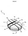
- FIG. 1shows an the implant 10 which generally includes a body 12 formed from a radio-lucent material, and at least one marker 14 associated with the body 12 and formed from a radio-opaque material.
- the body of the trial implantcan have virtually any configuration, depending on the intended use.
- the bodyshould, however, have a size and shape adapted to fit within an interstitial space, and more preferably the size and shape of the body should be identical or at least similar to the size and shape of a prosthesis desired to be implanted into a patient.
- FIG. 1illustrates one example of a trial implant 10 having a disc-shaped body 12 adapted to be positioned between adjacent vertebral bodies.
- the bodyincludes superior and inferior surfaces 16s, 16i, posterior and anterior sides 18p, 18a, first and second lateral sides 20a, 20b, respectively, and a perimeter P ( FIG. 2A ).
- the posterior side 18p of the illustrated body 12is preferably substantially flat, while the anterior side 18a and the first and second lateral sides 20a, 20b preferably form a curved convex portion of the perimeter P between opposite ends 18p 1 , 18p 2 of the flattened posterior side 18p.
- the superior and inferior surfaces 16s, 16i of the body 12can have a variety of shapes, sizes, and/or features present on one of both of the surfaces 16s, 16i.
- one or both of the surfaces 16s, 16ican have a wedge-like shape (not shown) wherein one side (e.g., posterior) of the body 12 member has a height less than a height of the opposed side (e.g., anterior) of the body 12.
- Other profilesinclude, for example, a supine shape, a converging portion, and a domed or convex-like profile.
- the trial implantcan be adapted to be used with either unprepared or prepared bony endplates of adjacent vertebrae.
- the trial implant 10further includes one or more markers that are effective to indicate, on an x-ray image, the size, shape, and/or position of the implant 10 with respect to adjacent bone structures.
- the markersare formed from a radio-opaque material and can have virtually any shape and size.
- FIG. 1illustrates one example of a trial implant 10 having several marker strips 14 that extend around the body 12. As shown, the marker strips 14 are formed from generally elongate strip-like members. Each strip 14 preferably has a width w sufficient to be detectable on an x-ray image. While the marker strips 14 are shown extending around the body 12, the marker strips 14 can alternatively, or in addition, have varying lengths and can be disposed at distinct positions on or within the body. For example, two marker strips 14 could be positioned to form an x-like marking to indicate a particular reference point on the body 12. A person having ordinary skill in the art will appreciate that the marker strips can vary in shape and size.
- FIGS. 2A-2Cillustrate implant 10 having five marker strips disposed around the body 12 to essentially outline the shape of the body 12.
- FIG. 2Aillustrates a superior view of the implant having marker strips 14a and 14b extending around the implant 10 between the first and second lateral sides 20a, 20b of the implant, and having marker strips 14c and 14d extending around the posterior and anterior sides 18a, 18p of the implant 10.
- FIG. 2Billustrates a lateral side view of the implant having an additional marker strip 14e that extends around the perimeter p of the implant 10.
- FIG. 2Cillustrates an additional, anterior view of the implant 10 having marker strips 14a-14e.
- FIG. 3illustrates an x-ray image of implant 10 having marker strips 14a-14e.
- marker strips 14c and 14deach extend around the implant 10 to form a generally rectangular object on the x-ray image.
- the corners of the marker stripscan be used as reference points.
- the marker strips 14c and 14dfurther intersect with marker strips 14a and 14b to form additional reference points (shown as white dots for reference purposes).
- four reference points 30sare positioned on the superior surface 16s of the implant, and four reference points 30i are positioned on the inferior surface 16i of the implant 10.
- the implant 10also includes two references points 301 on each of the lateral sides 20a, 20b, and two references points 30a on each of the anterior and posterior sides 18a, 18p.
- FIG. 4illustrates, for example, an implant 10 positioned between adjacent vertebrae 40, 42.
- the comers of marker strips 14a and 14bform reference points 32a, 32b, 32c, and 32d, which can be used to verify the alignment of the implant 10 with respect to the endplates of the adjacent vertebrae 40, 42.
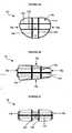
- FIGS. 5A-5Hillustrate additional embodiments of markers suitable for use with a trial implant.
- FIG. 5Aillustrates a marker strip 14a, which is essentially the same as the marker strip shown in the implant of FIGS. 1-4 .
- FIG. 5Billustrates a cylinder marker 14b, which is particularly useful in that an x-ray image of the cylinder marker 14b will appear as a circle if the implant is properly aligned.
- FIG. 5Cillustrates a ring marker 14c.
- the ring marker 14cis preferably used as an alignment guide in combination with a marker having a different shape. In use, an x-ray image of the ring marker 14c can be used to align another marker in the centre of the ring 14c.
- FIG. 5Aillustrates a marker strip 14a, which is essentially the same as the marker strip shown in the implant of FIGS. 1-4 .
- FIG. 5Billustrates a cylinder marker 14b, which is particularly useful in that an x-ray image of the
- FIG. 5Dillustrates another embodiment of a marker 14d having a spherical shape.
- the spherical marker 14dcan be used in combination with other spherical markers 14d such that an x-ray image of a properly aligned implant having two spheres 14d positioned along an axis will display only a single sphere 14d.
- FIG. 5Eillustrates a plate marker 14e having a substantially flattened rectangular shape.
- the plate marker 14eis particularly useful to indicate the angular relationship of the implant with respect to bone structures adjacent an interstitial space.
- the plate marker 14eis preferably used in combination with a ring marker 14c, cylinder marker 14b, or with additional plate markers 14e.
- FIG. 5Fillustrates a rod marker 14f, which is also preferably used to indicate the angular relationship of the marker 14f with respect to bone structures adjacent an interstitial space.
- the rod marker 14fwill appear as a single point on an x-ray image.
- FIGS. 5G and 5Hillustrate additional embodiments of markers.
- FIG. 5Gillustrates a marker 14g in the shape of a cross
- FIG. 5Hillustrates a T-shaped marker 14h.
- the cross and T-shaped markers 14g, 14hare preferably used in combination with the ring 14c, cylinder 14b, or spherical markers 14d, and will appear centred with respect to the other markers when properly aligned.
- Two T-shaped markers 14hcan also be positioned along an axis and inverted with respect to each other such that an x-ray image of the markers 14h, when properly aligned, will illustrate a cross or the letter "H," depending on the position of the markers 14h.
- the markers of the present inventioncan have virtually any configuration and can be used in combination with any number of markers having the same or a different configuration.
- a plurality of pairs of markersare positioned along a predetermined axis of the implant.
- An x-ray image, taken along a particular axis,can then be used to verify the alignment of the implant. If the implant is properly aligned, the pair of markers positioned along the axis will appear as a single marker, or will be displayed in some configuration indicative of alignment of the implant.
- the pairs of markersare preferably positioned on opposed sides of the implant to provide greater accuracy in alignment of the implant.
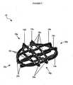
- FIG. 6Aillustrates an exemplary embodiment of an implant 1 Od having a body 12d with several sphere-shaped markers 14d positioned in pairs throughout the body 12d along predetermined axes t 1-4 , ⁇ 1-4 .
- Axes v 1 , v 2, v 3, and v 4extend between the superior and inferior surfaces 16s', 16i', axes t 3 and t 4 extend between the posterior and anterior sides 18p', 18a', and axes t 1 and t 2 extend between the first and second lateral sides 20a', 20b'.
- Two markersare positioned along each axis, as shown. In use, each marker pair can be used to determine the proper alignment of the implant.
- FIG. 1 , v 2, v 3, and v 4extend between the superior and inferior surfaces 16s', 16i', axes t 3 and t 4 extend between the posterior and anterior sides 18p', 18a', and axes t 1 and t 2 extend between the first and second
- FIG. 6Billustrates an x-ray image of a top view of the superior surface 16s' of the implant 10d.
- the pairs of markers that extend along axes v 1 , v 2 , v 3 , and v 4are each shown as a single marker 14d, thereby indicating that the implant is properly aligned.
- the pairs of markerswould each be displayed adjacent or offset from one another, as shown in FIG. 6C .
- FIG. 7Aillustrates another embodiment of a trial implant 10c having at least one pair of markers 14c, 14g positioned on opposed sides of the implant 10c along an axis t 5 .
- one of the markers 14cis in the shape of a ring
- the opposed marker 14gis in the shape of a cross.
- FIG. 7Billustrates an x-ray image of the implant 10c taken along axis t 5 .
- the implantis properly aligned since the x-ray image illustrates the cross-shaped marker 14g centred within the ring-shaped marker 14c.
- FIG. 7Cillustrates an example of the image of markers that is obtained in an improperly aligned implant in which the cross-shaped marker 14g is off-centre with respect to the ring-shaped maker 14c.
- the trial implant of the present inventioncan be provided as a system or kit containing several implantable trial implants.
- Each implantpreferably has a different shape and/or size, which is identical to, or similar to, a shape and size of an available prosthesis to be implanted.
- Each trial implantincludes a body formed from a radio-lucent material and having a size and shape adapted to fit within or adjacent to an anatomical structure, and a plurality of pairs of markers associated with the body and formed from a radio-opaque material.
- the marker stripsare configured to indicate, on an x-ray image, alignment of the body with respect to the anatomical structure when the implantable trial prosthesis is positioned within or adjacent to an anatomical structure.
- the surgeoncan select an implant from among several implants provided in the kit, and position and x-ray the implant to determine the fit. In the event that the selected trial implant does not fit appropriately, the surgeon can then select another implant from the kit. This process is repeated until the surgeon has selected the appropriately sized implant for that particular patient.
- a trial implantcan be manufactured by strategically placing a plurality of pairs of markers formed from a radio-opaque material into a mould having a desired size and shape for a medical implant.
- the plurality of pairs of markersare preferably positioned and configured to indicate, on an x-ray image, the alignment of the superior and inferior bone-contacting surfaces of the trial implant with respect to the endplates of the vertebral bodies.
- a radio-lucent materialcan then be injected into the mould to form a trial implant.
- the body 12is formed from a rigid, semi-rigid, or flexible radio-lucent material. More preferably, the body 12 is formed from materials such as polymers, ceramics, composite materials, and combinations thereof. Examples of suitable polymers include polyether sulphone, polycarbonate, and bioabsorbable polymers, and examples of suitable composites include carbon fibre reinforced polymers.
- the marker stripcan also be formed from a variety of radio-opaque materials including, for example, metals, polymers, filling salts, ceramics, and combinations thereof. Examples of suitable metals include titanium, stainless steel, tantalum, cobalt chromium, aluminum, and combinations thereof. A person having ordinary skill in the art will appreciate that the body can be formed from a radio-opaque material, and the marker strip can be formed from a radio-lucent material.
Landscapes
- Health & Medical Sciences (AREA)
- Transplantation (AREA)
- Orthopedic Medicine & Surgery (AREA)
- Heart & Thoracic Surgery (AREA)
- Cardiology (AREA)
- Oral & Maxillofacial Surgery (AREA)
- Engineering & Computer Science (AREA)
- Biomedical Technology (AREA)
- Physical Education & Sports Medicine (AREA)
- Vascular Medicine (AREA)
- Life Sciences & Earth Sciences (AREA)
- Animal Behavior & Ethology (AREA)
- General Health & Medical Sciences (AREA)
- Public Health (AREA)
- Veterinary Medicine (AREA)
- Prostheses (AREA)
Abstract
Description
- The present invention relates to a trial medical implant device, and more particularly, to a trial medical implant device for evaluating the size, shape, and alignment of the implant with respect to an anatomical structure. The present invention also relates to a method of manufacturing a trial implant device.
- Advancing age, as well as injuries, can lead to changes in the various bones, discs, joints and ligaments of the body. In particular, these changes can manifest themselves in the form of damage or degeneration of an intervertebral disc, the result of which is mild to severe chronic back pain. Intervertebral discs serve as "shock" absorbers for the spinal column, absorbing pressure delivered to the spinal column. Additionally, they maintain the proper anatomical separation between two adjacent vertebra. This separation is necessary for allowing both the afferent and efferent nerves to exit and enter, respectively, the spinal column.
- Treatment for a diseased or damaged disc can involve the removal of the natural, damaged disk tissue, and the subsequent replacement of the disc with an implant, such as an interbody cage or fusion device, or a disc prosthesis. The implant should have an appropriate size and shape to complement the normal height of the disc and to contour the vertebral endplates adjacent the disc space to provide stability and, if a fusion device is being implanted, to promote fusion. If the shape of the vertebral endplates does not match the shape of the implant, shifting can occur resulting in misalignment of the vertebrae. Accordingly, it is important for the implant to correspond as closely as possible to the region of the intradiscal space that is receiving the implant.
- Selection of a properly sized implant can be difficult due to the enclosed nature of the nucleus cavity. X-rays generally reveal very little about the particular size and shape of the intradiscal space, and thus surgeons often have to rely on an estimated shape and size based on physiological factors, such as the patient's height, weight, etc., as well as the position of the vertebrae. While this method can be sufficient, the selection of an improperly sized implant can lead to problems. An oversized implant, for example, will be difficult to position between the adjacent vertebrae and can lead to long term problems once implanted. Moreover, due to the enclosed nature of the nucleus cavity, it is virtually impossible for a surgeon to accurately evaluate the size and shape of the cavity, much less the matching of the implant with the vertebral endplates. Unfortunately, the sizing problem is not always discovered until the surgeon attempts to position the implant between the vertebrae. As a result, the implant will have been in direct contact with bodily fluids and will be contaminated. Some implants can be virtually impossible to resterilise due to the nature of the materials from which they are made. In such cases, it is necessary to discard an expensive device.
- To overcome this problem, trial implants and trial implant kits have been developed to assist surgeons in selecting an implant having the appropriate size and shape.
US-6113639 discloses, for example, a trial implant kit containing several trial implants, each sized and shaped to simulate the size and shape of an available prosthetic implant. The surgeon can select an implant from the kit to temporarily position within the disc space to evaluate the size of the intradiscal space and the fit of a sample prosthesis. A contrast material can be injected into the nucleus cavity to view the trial implant with respect to the intradiscal space via a fluoroscope. - While fluoroscopy or x-ray can be effective to verify the placement of a trial implant, the image produced can be distorted by the large, opaque implant. This distortion can either shield or completely obscure the anatomical matching that the surgeon desires to verify. It can also be difficult to accurately assess whether the implant is in close contact with the complex geometries of the adjacent vertebral endplates.
- Intervertebral implants having radio-opaque markers that help to determine the position of the implant within the spine are known from
WO 01/70144 A - Accordingly, there is a need for a trial implant that can be used to accurately and effectively evaluate the size, shape, and alignment of the implant with respect to an anatomical structure.
- This is achieved by a trial implant according to claim 1.
- The present invention provides a trial implant for assisting a physician in selecting an appropriately sized prosthesis. The trial implant is effective to indicate, on an x-ray image, the shape, size, and/or position of the implant with respect to an anatomical structure when the implant is positioned within or adjacent the anatomical structure.
- The trial implant assists a physician in selecting an appropriately sized prosthesis. In one embodiment, the trial medical implant device includes a body formed from a radio-lucent material and having a size and shape adapted to fit within or adjacent to an interstitial space, and a plurality of pairs of markers associated with the body and formed from a radio-opaque material. The plurality of pairs of markers is configured to provide an x-ray visible reference to indicate the position and alignment of the body with respect to an anatomical structure when the trial medical implant device is positioned within an interstitial space.
- The markers can be disposed on an outer surface of the body and/or embedded in the body. In one embodiment, the implant includes several markers, each of which can be selectively positioned to intersect to form one or more reference points on the body. Thus, when implanted in the body, an x-ray image can be used to determine the exact position of the implant with respect to an anatomical structure. In another embodiment, the implant can include first and second markers that are selectively distinguishable on an x-ray image. Each marker can have a variety of shapes, and can be in the form of a tube, cross, sphere, plate, ring, rod, T-shape, and combinations thereof.
- In further aspects of the present invention, the body of the implant has a shape and size adapted to fit between adjacent vertebral bodies. By way of non-limiting example, the body can be a disc-shaped member having a superior, bone-contacting surface and an inferior, bone-contacting surface. The plurality of pairs of markers is preferably effective to indicate the alignment of the superior and inferior bone-contacting surfaces of the body with respect to superior and inferior endplates of adjacent vertebral bodies when the implant is positioned between adjacent vertebral bodies.
- In another embodiment of the present invention, a trial spinal implant is provided having a trial implant member formed from a radio-lucent material and having a size and shape configured to fit between adjacent vertebral bodies. The trial implant member includes a superior bone-contacting surface and an inferior bone-contacting surface. A plurality of pairs of markers formed from a radio-opaque material is associated with the trial implant member such that, when the trial implant is positioned between adjacent vertebral bodies, the markers provide at least one x-ray visible reference to indicate the position and/or alignment of the implant with respect to the adjacent vertebral bodies. In a preferred embodiment, the superior and inferior bone-contacting surfaces of the trial implant member each have a shape adapted to conform to an endplate of an adjacent vertebral body. Thus, when implanted in the body, the plurality of pairs of markers indicates, on an x-ray image, the alignment of the superior and inferior bone-contacting surfaces of the trial implant member with respect to the endplates of adjacent vertebral bodies.
- In yet another embodiment, a trial implant system is provided having a plurality of implantable trial prostheses. Each implantable prosthesis includes a body formed from a radio-lucent material and having a size and shape adapted to fit within or adjacent to an anatomical structure, and a plurality of pairs of markers associated with the body and formed from a radio-opaque material. The plurality of pairs of markers is configured to provide an x-ray visible reference to indicate the position and alignment of the body with respect to the anatomical structure when the implantable trial prosthesis is positioned within or adjacent to an anatomical structure.
- In other aspects of the present invention, a method for manufacturing a trial implant is provided. The method includes the steps of providing a plurality of pairs of markers formed from a radio-opaque material, providing a mould having a desired size and shape for a medical implant, strategically placing each of the plurality of pairs of markers in the mould such that the markers are configured to provide at least one x-ray visible reference to indicate the alignement of the superior and inferior bone-contacting surfaces of the trial spinal implant with respect to the endplates of the vertebral bodies, and injecting a radio-lucent material into the mould to form a trial implant.
- Different embodiments will now be described by way of example with reference to the accompanying drawings, in which:
FIG. 1 is a anterior perspective view of a trial implant member ;FIGS. 2A-2C are top, lateral side, and anterior side views, respectively, of the trial implant ofFIG. 1 ;FIG. 3 is a posterior perspective view illustrating the radio-lucent marking strips of a trial implant member ;FIG. 4 is a side view illustration of a trial implant member positioned between adjacent vertebrae;FIGS. 5A-5H illustrate several embodiments of markers for use with an implant according to the present invention;FIG. 6A illustrates a perspective view of a trial implant according to the present invention having several radio-lucent sphere markers positioned around and/or within the implant;FIG. 6B illustrates a top view of the implant ofFIG. 6A ;FIG. 6C illustrates two misaligned sphere markers;FIG. 7A illustrates a perspective view of yet another embodiment of a trial implant having several radio-lucent markers positioned around and/or within the implant;FIG. 7B illustrates a front view of the trial implant ofFIG. 7A ; andFIG. 7C illustrates a ring marker and a cross marker being misaligned with respect to each other.- Referring to the drawings,
FIG. 1 shows an theimplant 10 which generally includes abody 12 formed from a radio-lucent material, and at least onemarker 14 associated with thebody 12 and formed from a radio-opaque material. - The body of the trial implant can have virtually any configuration, depending on the intended use. The body should, however, have a size and shape adapted to fit within an interstitial space, and more preferably the size and shape of the body should be identical or at least similar to the size and shape of a prosthesis desired to be implanted into a patient.
FIG. 1 illustrates one example of atrial implant 10 having a disc-shapedbody 12 adapted to be positioned between adjacent vertebral bodies. The body includes superior andinferior surfaces anterior sides lateral sides FIG. 2A ). While thebody 12 can have any shape, theposterior side 18p of the illustratedbody 12 is preferably substantially flat, while theanterior side 18a and the first and secondlateral sides opposite ends posterior side 18p. - A person having ordinary skill in the art will appreciate that the superior and
inferior surfaces body 12 can have a variety of shapes, sizes, and/or features present on one of both of thesurfaces surfaces body 12 member has a height less than a height of the opposed side (e.g., anterior) of thebody 12. Other profiles include, for example, a supine shape, a converging portion, and a domed or convex-like profile. One of ordinary skill in the art will appreciate that various combinations of these profiles may be used as well. Moreover, the trial implant can be adapted to be used with either unprepared or prepared bony endplates of adjacent vertebrae. - The
trial implant 10 further includes one or more markers that are effective to indicate, on an x-ray image, the size, shape, and/or position of theimplant 10 with respect to adjacent bone structures. The markers are formed from a radio-opaque material and can have virtually any shape and size.FIG. 1 illustrates one example of atrial implant 10 having several marker strips 14 that extend around thebody 12. As shown, the marker strips 14 are formed from generally elongate strip-like members. Eachstrip 14 preferably has a width w sufficient to be detectable on an x-ray image. While the marker strips 14 are shown extending around thebody 12, the marker strips 14 can alternatively, or in addition, have varying lengths and can be disposed at distinct positions on or within the body. For example, twomarker strips 14 could be positioned to form an x-like marking to indicate a particular reference point on thebody 12. A person having ordinary skill in the art will appreciate that the marker strips can vary in shape and size. - The position of the marker strips 14 on the
body 12 can also vary, but preferably thestrips 14 are strategically positioned around and/or within thebody 12 of theimplant 10 to assist a physician in assessing the size, shape, and/or alignment of theimplant 10, via an x-ray image, with respect to bone structures surrounding an interstitial space.FIGS. 2A-2C , for example, illustrateimplant 10 having five marker strips disposed around thebody 12 to essentially outline the shape of thebody 12.FIG. 2A illustrates a superior view of the implant havingmarker strips implant 10 between the first and secondlateral sides anterior sides implant 10.FIG. 2B illustrates a lateral side view of the implant having anadditional marker strip 14e that extends around the perimeterp of theimplant 10.FIG. 2C illustrates an additional, anterior view of theimplant 10 havingmarker strips 14a-14e. FIG. 3 illustrates an x-ray image ofimplant 10 havingmarker strips 14a-14e. As shown, marker strips 14c and 14d each extend around theimplant 10 to form a generally rectangular object on the x-ray image. The corners of the marker strips can be used as reference points. The marker strips 14c and 14d further intersect withmarker strips reference points 30s are positioned on thesuperior surface 16s of the implant, and fourreference points 30i are positioned on theinferior surface 16i of theimplant 10. Theimplant 10 also includes tworeferences points 301 on each of thelateral sides references points 30a on each of the anterior andposterior sides - In use, the surgeon can determine the shape, size, and/or position of the implant with respect to adjacent vertebral bodies based on reference points determined by the intersection of two marker strips 14, as well as the shape of each
marker strip 14. Several x-ray images can be taken to display particular reference points.FIG. 4 illustrates, for example, animplant 10 positioned betweenadjacent vertebrae marker strips form reference points implant 10 with respect to the endplates of theadjacent vertebrae FIGS. 5A-5H illustrate additional embodiments of markers suitable for use with a trial implant.FIG. 5A illustrates amarker strip 14a, which is essentially the same as the marker strip shown in the implant ofFIGS. 1-4 .FIG. 5B illustrates acylinder marker 14b, which is particularly useful in that an x-ray image of thecylinder marker 14b will appear as a circle if the implant is properly aligned.FIG. 5C illustrates aring marker 14c. Thering marker 14c is preferably used as an alignment guide in combination with a marker having a different shape. In use, an x-ray image of thering marker 14c can be used to align another marker in the centre of thering 14c.FIG. 5D illustrates another embodiment of amarker 14d having a spherical shape. Thespherical marker 14d can be used in combination with otherspherical markers 14d such that an x-ray image of a properly aligned implant having twospheres 14d positioned along an axis will display only asingle sphere 14d.FIG. 5E illustrates aplate marker 14e having a substantially flattened rectangular shape. Theplate marker 14e is particularly useful to indicate the angular relationship of the implant with respect to bone structures adjacent an interstitial space. Theplate marker 14e is preferably used in combination with aring marker 14c,cylinder marker 14b, or withadditional plate markers 14e.FIG. 5F illustrates arod marker 14f, which is also preferably used to indicate the angular relationship of themarker 14f with respect to bone structures adjacent an interstitial space. When the implant is properly aligned, therod marker 14f will appear as a single point on an x-ray image.FIGS. 5G and 5H illustrate additional embodiments of markers.FIG. 5G illustrates amarker 14g in the shape of a cross, andFIG. 5H illustrates a T-shapedmarker 14h. The cross and T-shapedmarkers ring 14c,cylinder 14b, orspherical markers 14d, and will appear centred with respect to the other markers when properly aligned. Two T-shapedmarkers 14h can also be positioned along an axis and inverted with respect to each other such that an x-ray image of themarkers 14h, when properly aligned, will illustrate a cross or the letter "H," depending on the position of themarkers 14h. A person having ordinary skill in the art will appreciate that the markers of the present invention can have virtually any configuration and can be used in combination with any number of markers having the same or a different configuration.- In the implant according to the invention a plurality of pairs of markers are positioned along a predetermined axis of the implant. An x-ray image, taken along a particular axis, can then be used to verify the alignment of the implant. If the implant is properly aligned, the pair of markers positioned along the axis will appear as a single marker, or will be displayed in some configuration indicative of alignment of the implant. The pairs of markers are preferably positioned on opposed sides of the implant to provide greater accuracy in alignment of the implant.
FIG. 6A illustrates an exemplary embodiment of an implant 1 Od having abody 12d with several sphere-shapedmarkers 14d positioned in pairs throughout thebody 12d along predetermined axest1-4, ν1-4. Axes v1, v2, v3, and v4 extend between the superior andinferior surfaces 16s', 16i', axes t3 and t4 extend between the posterior andanterior sides 18p', 18a', and axes t1 and t2 extend between the first and secondlateral sides 20a', 20b'. Two markers are positioned along each axis, as shown. In use, each marker pair can be used to determine the proper alignment of the implant.FIG. 6B , for example, illustrates an x-ray image of a top view of thesuperior surface 16s' of theimplant 10d. The pairs of markers that extend along axes v1, v2, v3, and v4 are each shown as asingle marker 14d, thereby indicating that the implant is properly aligned. In the event theimplant 10 is not properly aligned once implanted in a patient's body, the pairs of markers would each be displayed adjacent or offset from one another, as shown inFIG. 6C .FIG. 7A illustrates another embodiment of atrial implant 10c having at least one pair ofmarkers implant 10c along an axist5. As shown, one of themarkers 14c is in the shape of a ring, and theopposed marker 14g is in the shape of a cross.FIG. 7B illustrates an x-ray image of theimplant 10c taken along axist5. The implant is properly aligned since the x-ray image illustrates thecross-shaped marker 14g centred within the ring-shapedmarker 14c.FIG. 7C illustrates an example of the image of markers that is obtained in an improperly aligned implant in which thecross-shaped marker 14g is off-centre with respect to the ring-shapedmaker 14c.- The trial implant of the present invention can be provided as a system or kit containing several implantable trial implants. Each implant preferably has a different shape and/or size, which is identical to, or similar to, a shape and size of an available prosthesis to be implanted. Each trial implant includes a body formed from a radio-lucent material and having a size and shape adapted to fit within or adjacent to an anatomical structure, and a plurality of pairs of markers associated with the body and formed from a radio-opaque material. The marker strips are configured to indicate, on an x-ray image, alignment of the body with respect to the anatomical structure when the implantable trial prosthesis is positioned within or adjacent to an anatomical structure. In use, the surgeon can select an implant from among several implants provided in the kit, and position and x-ray the implant to determine the fit. In the event that the selected trial implant does not fit appropriately, the surgeon can then select another implant from the kit. This process is repeated until the surgeon has selected the appropriately sized implant for that particular patient.
- The trial implants of the present invention can be manufactured using a variety of techniques. In one embodiment, a trial implant can be manufactured by strategically placing a plurality of pairs of markers formed from a radio-opaque material into a mould having a desired size and shape for a medical implant. The plurality of pairs of markers are preferably positioned and configured to indicate, on an x-ray image, the alignment of the superior and inferior bone-contacting surfaces of the trial implant with respect to the endplates of the vertebral bodies. A radio-lucent material can then be injected into the mould to form a trial implant. A person having ordinary skill in the art will appreciate that a variety of techniques can be utilized to manufacture a trial implant according to the present invention.
- The materials used for form a trial implant according to the present invention can vary. Preferably, the
body 12 is formed from a rigid, semi-rigid, or flexible radio-lucent material. More preferably, thebody 12 is formed from materials such as polymers, ceramics, composite materials, and combinations thereof. Examples of suitable polymers include polyether sulphone, polycarbonate, and bioabsorbable polymers, and examples of suitable composites include carbon fibre reinforced polymers. The marker strip can also be formed from a variety of radio-opaque materials including, for example, metals, polymers, filling salts, ceramics, and combinations thereof. Examples of suitable metals include titanium, stainless steel, tantalum, cobalt chromium, aluminum, and combinations thereof. A person having ordinary skill in the art will appreciate that the body can be formed from a radio-opaque material, and the marker strip can be formed from a radio-lucent material.
Claims (13)
- A trial medical implant device (10d), comprising:a body (12d) formed from a radio-lucent material and having a size and shape adapted to fit within or adjacent to an interstitial space; anda plurality of pairs of markers (14d) formed from a radio-opaque material, each pair being selectively positioned along a predetermined axis (t1, t2,13, t4; v1, v2, v3, v4) with respect to the body such that an x-ray visible reference of a pair of markers, taken along a predetermined axis indicates the position and alignment of the body with respect to an anatomical structure (40. 42) when the trial medical implant device is positioned within an interstitial space.
- The trial medical implant device of claim 1, wherein at least one of the markers is selectively distinguishable, on an x-ray image, from another one of the markers.
- The trial medical implant device of claim 1, wherein the markers have shapes selected from the group consisting of an elongate strip (14a), a tube (14b), a cross (14g), a sphere (14d), a plate (14e), a ring (14c), a rod (14f), a T-shape (14h), and combinations thereof.
- The trial medical implant device of claim 1, wherein the markers arc disposed on an outer surface (16s', 16i', 18a', 18p', 20a', 20b') of the body or embedded in the body.
- The trial medical implant device of claim 1, wherein at least one marker is disposed on an outer surface of the body and at least one marker is embedded in the body.
- The trial medical implant device of claim 1, wherein the body has a shape and size adapted to fit between adjacent vertebral bodies (40, 42).
- The trial medical implant, device of claim 6. wherein the body is a disc-shaped member having a superior, hone-contacting surface (16s') and an inferior, bone-contacting surface (16i'), and wherein the markers are effective to indicate the alignment of the superior and inferior bone-contacting surfaces of the body with respect to superior and inferior endplates of adjacent vertebral bodies when the implant is positioned between adjacent vertebral bodies.
- The trial medical implant device of claim 1, wherein the body is formed from materials selected from the group consisting of polymers, ceramics, composite materials, and combinations thereof.
- The trial medical implant device of claim 8, wherein the polymers are selected from the group consisting of polyether sulphone, polycarbonate, bioabsorbable polymers, carbon fibre reinforced polymers, and combinations thereof.
- The trial medical implant device of claim 1, wherein the markers are formed from a material selected from the group consisting of metals, polymers, filling salts, ceramics, and combinations thereof.
- The trial medical implant device of claim 10, wherein the metals are selected from the group consisting of titanium, stainless steel, tantalum, cobalt chromium, aluminum, and combinations thereof.
- The trial medical implant device of claim 1, wherein the body includes superior and inferior bone-contacting surfaces, each having a shape adapted to conform to an endplate of a vertebral body, and wherein the plurality of pairs of markers indicate, on an x-ray image, the alignment or the superior and inferior bone-contacting surfaces of the body with respect to the endplates of adjacent vertebral bodies when the trial medical implant device is positioned within the interstitial space.
- A method for manufacturing a trial spinal implant, comprising:providing a plurality of pairs of markers formed from a radio-opaque material;providing a mould for a substantially disc shaped spinal implant having superior and inferior bone-contacting surfaces, each having a shape adapted to conform to an endplate of an adjacent vertebral body;strategically placing each of the plurality of pairs of markers in the mould; andinjecting a radio-lucent material into the mould to form a trial implant;wherein the plurality of pairs of markers are strategically placed in the mould such that each pair is positioned along a predetermined axis with respect to the mould so that an x-ray visible reference of a pair of markers, taken along a predetermined axis, indicates the alignment of the superior and inferior bone-contacting surfaces of the trial spinal implant with respect to the endplates of the vertebral bodies.
Applications Claiming Priority (2)
| Application Number | Priority Date | Filing Date | Title |
|---|---|---|---|
| US200890 | 2002-07-23 | ||
| US10/200,890US6723097B2 (en) | 2002-07-23 | 2002-07-23 | Surgical trial implant |
Publications (2)
| Publication Number | Publication Date |
|---|---|
| EP1384455A1 EP1384455A1 (en) | 2004-01-28 |
| EP1384455B1true EP1384455B1 (en) | 2010-01-27 |
Family
ID=30000077
Family Applications (1)
| Application Number | Title | Priority Date | Filing Date |
|---|---|---|---|
| EP03254180AExpired - LifetimeEP1384455B1 (en) | 2002-07-23 | 2003-07-01 | Surgical trial implant |
Country Status (7)
| Country | Link |
|---|---|
| US (1) | US6723097B2 (en) |
| EP (1) | EP1384455B1 (en) |
| JP (1) | JP2004130097A (en) |
| AT (1) | ATE456339T1 (en) |
| AU (1) | AU2003204910B2 (en) |
| CA (1) | CA2435862A1 (en) |
| DE (1) | DE60331120D1 (en) |
Cited By (1)
| Publication number | Priority date | Publication date | Assignee | Title |
|---|---|---|---|---|
| US7753941B2 (en) | 2000-04-04 | 2010-07-13 | Anulex Technologies, Inc. | Devices and methods for annular repair of intervertebral discs |
Families Citing this family (126)
| Publication number | Priority date | Publication date | Assignee | Title |
|---|---|---|---|---|
| US8128698B2 (en) | 1999-10-20 | 2012-03-06 | Anulex Technologies, Inc. | Method and apparatus for the treatment of the intervertebral disc annulus |
| US7951201B2 (en) | 1999-10-20 | 2011-05-31 | Anulex Technologies, Inc. | Method and apparatus for the treatment of the intervertebral disc annulus |
| US7052516B2 (en) | 1999-10-20 | 2006-05-30 | Anulex Technologies, Inc. | Spinal disc annulus reconstruction method and deformable spinal disc annulus stent |
| US7004970B2 (en) | 1999-10-20 | 2006-02-28 | Anulex Technologies, Inc. | Methods and devices for spinal disc annulus reconstruction and repair |
| US7935147B2 (en) | 1999-10-20 | 2011-05-03 | Anulex Technologies, Inc. | Method and apparatus for enhanced delivery of treatment device to the intervertebral disc annulus |
| US6592625B2 (en) | 1999-10-20 | 2003-07-15 | Anulex Technologies, Inc. | Spinal disc annulus reconstruction method and spinal disc annulus stent |
| US7615076B2 (en) | 1999-10-20 | 2009-11-10 | Anulex Technologies, Inc. | Method and apparatus for the treatment of the intervertebral disc annulus |
| US8632590B2 (en) | 1999-10-20 | 2014-01-21 | Anulex Technologies, Inc. | Apparatus and methods for the treatment of the intervertebral disc |
| US6402750B1 (en)* | 2000-04-04 | 2002-06-11 | Spinlabs, Llc | Devices and methods for the treatment of spinal disorders |
| US7695521B2 (en) | 2001-05-01 | 2010-04-13 | Amedica Corporation | Hip prosthesis with monoblock ceramic acetabular cup |
| US20050177238A1 (en)* | 2001-05-01 | 2005-08-11 | Khandkar Ashok C. | Radiolucent bone graft |
| US7776085B2 (en)* | 2001-05-01 | 2010-08-17 | Amedica Corporation | Knee prosthesis with ceramic tibial component |
| US6974480B2 (en) | 2001-05-03 | 2005-12-13 | Synthes (Usa) | Intervertebral implant for transforaminal posterior lumbar interbody fusion procedure |
| EP1408874B1 (en)* | 2001-06-14 | 2012-08-08 | Amedica Corporation | Metal-ceramic composite articulation |
| AU2003226586A1 (en) | 2002-09-19 | 2004-04-08 | Malan De Villiers | Intervertebral prosthesis |
| US20040068320A1 (en)* | 2002-10-04 | 2004-04-08 | Robie Bruce H. | Prosthetic disc and vertebral body replacement device having pyrolytic carbon bearing members |
| GB0223327D0 (en)* | 2002-10-08 | 2002-11-13 | Ranier Ltd | Artificial spinal disc |
| AU2003297195A1 (en)* | 2002-12-17 | 2004-07-22 | Amedica Corporation | Total disc implant |
| WO2004066884A1 (en) | 2003-01-31 | 2004-08-12 | Spinalmotion, Inc. | Intervertebral prosthesis placement instrument |
| ZA200506029B (en)* | 2003-01-31 | 2006-10-25 | Spinalmotion Inc | Spinal Midline Indicator |
| WO2004084742A1 (en)* | 2003-03-24 | 2004-10-07 | Theken Surgical Llc | Spinal implant adjustment device |
| DE10316558B4 (en)* | 2003-04-10 | 2005-03-31 | Siemens Ag | Method for detecting changes in position of an implant and X-ray system for carrying out the method |
| US20050143824A1 (en)* | 2003-05-06 | 2005-06-30 | Marc Richelsoph | Artificial intervertebral disc |
| US7291173B2 (en) | 2003-05-06 | 2007-11-06 | Aesculap Ii, Inc. | Artificial intervertebral disc |
| US7105024B2 (en)* | 2003-05-06 | 2006-09-12 | Aesculap Ii, Inc. | Artificial intervertebral disc |
| DE10324108B3 (en)* | 2003-05-21 | 2005-01-27 | Aesculap Ag & Co. Kg | Backbone implant is inserted with contracted contact disc which is expanded to optimum area following insertion |
| US7575599B2 (en) | 2004-07-30 | 2009-08-18 | Spinalmotion, Inc. | Intervertebral prosthetic disc with metallic core |
| US7442211B2 (en) | 2003-05-27 | 2008-10-28 | Spinalmotion, Inc. | Intervertebral prosthetic disc |
| US10052211B2 (en) | 2003-05-27 | 2018-08-21 | Simplify Medical Pty Ltd. | Prosthetic disc for intervertebral insertion |
| US20090076614A1 (en)* | 2007-09-17 | 2009-03-19 | Spinalmotion, Inc. | Intervertebral Prosthetic Disc with Shock Absorption Core |
| DE10330698B4 (en)* | 2003-07-08 | 2005-05-25 | Aesculap Ag & Co. Kg | Intervertebral implant |
| DE20310433U1 (en) | 2003-07-08 | 2003-09-04 | Aesculap AG & Co. KG, 78532 Tuttlingen | Surgical device for inserting dual component implant into appropriate space at spine, comprising particularly shaped holding area |
| DE10339170B4 (en)* | 2003-08-22 | 2009-10-15 | Aesculap Ag | Intervertebral implant |
| DE20315613U1 (en)* | 2003-10-08 | 2003-12-11 | Aesculap Ag & Co. Kg | Intervertebral implant |
| US7485145B2 (en)* | 2004-02-23 | 2009-02-03 | Alphatec Spine, Incorporated | Artificial intervertebral disc assembly |
| US7918891B1 (en)* | 2004-03-29 | 2011-04-05 | Nuvasive Inc. | Systems and methods for spinal fusion |
| US7544208B1 (en) | 2004-05-03 | 2009-06-09 | Theken Spine, Llc | Adjustable corpectomy apparatus |
| DE202004009542U1 (en)* | 2004-06-16 | 2004-08-12 | Aesculap Ag & Co. Kg | Artificial intervertebral disk, comprising core with intensely curved upper and less curved lower surface |
| US20060009541A1 (en)* | 2004-07-09 | 2006-01-12 | Yih-Fang Chen | Saturant for friction material containing friction modifying layer |
| US7585326B2 (en) | 2004-08-06 | 2009-09-08 | Spinalmotion, Inc. | Methods and apparatus for intervertebral disc prosthesis insertion |
| KR20120102806A (en)* | 2004-09-23 | 2012-09-18 | 스파인 소루션 아이앤씨 | System and method for an intervertebral implant |
| US7763024B2 (en)* | 2004-09-23 | 2010-07-27 | Spine Solutions, Inc. | Adjustable cutting of cutout in vertebral bone |
| US8083797B2 (en) | 2005-02-04 | 2011-12-27 | Spinalmotion, Inc. | Intervertebral prosthetic disc with shock absorption |
| US20060229723A1 (en)* | 2005-04-08 | 2006-10-12 | Sdgi Holdings, Inc. | Intervertebral fusion device and method |
| CA2618771C (en)* | 2005-08-10 | 2015-03-24 | Synthes (U.S.A.) | Porous implant |
| AU2006282828B2 (en) | 2005-08-23 | 2013-01-31 | Smith & Nephew, Inc | Telemetric orthopaedic implant |
| US8167915B2 (en)* | 2005-09-28 | 2012-05-01 | Nuvasive, Inc. | Methods and apparatus for treating spinal stenosis |
| US7862592B2 (en)* | 2005-12-06 | 2011-01-04 | Nuvasive, Inc. | Methods and apparatus for treating spinal stenosis |
| US8252058B2 (en)* | 2006-02-16 | 2012-08-28 | Amedica Corporation | Spinal implant with elliptical articulatory interface |
| US20070198093A1 (en)* | 2006-02-17 | 2007-08-23 | Amedica Corporation | Spinal implant with offset keels |
| US9849216B2 (en) | 2006-03-03 | 2017-12-26 | Smith & Nephew, Inc. | Systems and methods for delivering a medicament |
| US8333805B2 (en) | 2006-03-20 | 2012-12-18 | Howmedica Osteonics Corp. | Composite joint implant |
| WO2007121320A2 (en)* | 2006-04-12 | 2007-10-25 | Spinalmotion, Inc. | Posterior spinal device and method |
| US7998180B2 (en)* | 2006-04-28 | 2011-08-16 | Warsaw Orthopedic, Inc. | Radiolucent bone plate systems and methods of use |
| US20070276492A1 (en)* | 2006-05-09 | 2007-11-29 | Ranier Limited | Artificial spinal disc implant |
| US8834526B2 (en) | 2006-08-09 | 2014-09-16 | Rolando Garcia | Methods and apparatus for treating spinal stenosis |
| US7686809B2 (en) | 2006-09-25 | 2010-03-30 | Stryker Spine | Rod inserter and rod with reduced diameter end |
| US8162952B2 (en) | 2006-09-26 | 2012-04-24 | Ebi, Llc | Percutaneous instrument assembly |
| US8038699B2 (en) | 2006-09-26 | 2011-10-18 | Ebi, Llc | Percutaneous instrument assembly |
| US20080140204A1 (en)* | 2006-12-07 | 2008-06-12 | Warsaw Orthopedic, Inc. | Vertebral Implant Systems and Methods of Use |
| US8673005B1 (en) | 2007-03-07 | 2014-03-18 | Nuvasive, Inc. | System and methods for spinal fusion |
| US10335288B2 (en) | 2007-03-10 | 2019-07-02 | Spinesmith Partners, L.P. | Surgical implant secured by pegs and associated methods |
| US9289310B2 (en) | 2007-03-10 | 2016-03-22 | Spinesmith Partners, L.P. | Artificial disc with post and modular collar |
| US9358121B2 (en)* | 2007-03-10 | 2016-06-07 | Spinesmith Partners, L.P. | Artificial disc with unique articulating geometry and associated methods |
| US11298241B2 (en) | 2007-03-29 | 2022-04-12 | Life Spine, Inc. | Radially expandable spinal interbody device and implantation tool |
| US10251759B2 (en)* | 2007-03-29 | 2019-04-09 | Life Spine, Inc. | Radially expandable spinal interbody device and implantation tool |
| US20080306598A1 (en)* | 2007-04-02 | 2008-12-11 | Eric Hansen | Spinal implant with biologic sponge |
| US20080243252A1 (en)* | 2007-04-02 | 2008-10-02 | Centra-Fuse, Inc. | Spinal implant system |
| US7822465B2 (en)* | 2007-04-25 | 2010-10-26 | Warsaw Orthopedic, Inc. | Device and method for image-based device performance measurement |
| US20100191333A1 (en)* | 2007-06-08 | 2010-07-29 | Morrison Iii Thomas J | Load-bearing spinal interbody device |
| ES2651269T3 (en) | 2007-06-20 | 2018-01-25 | Medical Components, Inc. | Venous reservoir with molded indications and / or radiopacas |
| WO2009012385A1 (en) | 2007-07-19 | 2009-01-22 | Medical Components, Inc. | Venous access port assembly with x-ray discernable indicia |
| US9610432B2 (en) | 2007-07-19 | 2017-04-04 | Innovative Medical Devices, Llc | Venous access port assembly with X-ray discernable indicia |
| US20090043391A1 (en) | 2007-08-09 | 2009-02-12 | Spinalmotion, Inc. | Customized Intervertebral Prosthetic Disc with Shock Absorption |
| US20090105834A1 (en) | 2007-10-22 | 2009-04-23 | Spinalmotion, Inc. | Dynamic Spacer Device and Method for Spanning a Space Formed upon Removal of an Intervertebral Disc |
| US8083796B1 (en) | 2008-02-29 | 2011-12-27 | Nuvasive, Inc. | Implants and methods for spinal fusion |
| US8764833B2 (en) | 2008-03-11 | 2014-07-01 | Spinalmotion, Inc. | Artificial intervertebral disc with lower height |
| US9034038B2 (en) | 2008-04-11 | 2015-05-19 | Spinalmotion, Inc. | Motion limiting insert for an artificial intervertebral disc |
| US20090270988A1 (en)* | 2008-04-24 | 2009-10-29 | Ranier Limited | Artificial spinal disc implant |
| WO2009132302A1 (en) | 2008-04-25 | 2009-10-29 | Pioneer Surgical Technology, Inc. | Bone plate system |
| EP2278941A1 (en) | 2008-05-05 | 2011-02-02 | Spinalmotion Inc. | Polyaryletherketone artificial intervertebral disc |
| EP2328519B1 (en)* | 2008-06-05 | 2014-12-31 | Alphatec Spine, Inc. | Modular anterior locking interbody cage |
| US9220603B2 (en) | 2008-07-02 | 2015-12-29 | Simplify Medical, Inc. | Limited motion prosthetic intervertebral disc |
| EP2299944A4 (en) | 2008-07-17 | 2013-07-31 | Spinalmotion Inc | SYSTEM FOR INSTALLING ARTIFICIAL INTERVERTEBRAL DISCS |
| EP2299941A1 (en) | 2008-07-18 | 2011-03-30 | Spinalmotion Inc. | Posterior prosthetic intervertebral disc |
| US8292923B1 (en) | 2008-10-13 | 2012-10-23 | Nuvasive, Inc. | Systems and methods for treating spinal stenosis |
| US8163022B2 (en) | 2008-10-14 | 2012-04-24 | Anulex Technologies, Inc. | Method and apparatus for the treatment of the intervertebral disc annulus |
| BRPI0920250A2 (en) | 2008-10-15 | 2016-11-22 | Smith & Nephew Inc | composite internal fasteners |
| USD754346S1 (en) | 2009-03-02 | 2016-04-19 | Nuvasive, Inc. | Spinal fusion implant |
| EP2432429B1 (en) | 2009-05-19 | 2016-03-30 | Synthes GmbH | Dynamic trial implants |
| US9655658B2 (en) | 2009-10-14 | 2017-05-23 | Ebi, Llc | Deformable device for minimally invasive fixation |
| US9028553B2 (en) | 2009-11-05 | 2015-05-12 | DePuy Synthes Products, Inc. | Self-pivoting spinal implant and associated instrumentation |
| US8652153B2 (en) | 2010-01-11 | 2014-02-18 | Anulex Technologies, Inc. | Intervertebral disc annulus repair system and bone anchor delivery tool |
| GB201006716D0 (en)* | 2010-04-22 | 2010-06-09 | Depuy Ireland | A composite trial prosthesis |
| US8353964B2 (en) | 2010-11-04 | 2013-01-15 | Carpenter Clyde T | Anatomic total disc replacement |
| GB201108185D0 (en)* | 2011-05-17 | 2011-06-29 | Depuy Spine Sarl | Medical implant, method for manufacturing a medical implant and curable mixture |
| US20120316430A1 (en)* | 2011-06-10 | 2012-12-13 | Cibor, Inc. | Radiolucent surgical instruments |
| US8968412B2 (en) | 2011-06-30 | 2015-03-03 | Depuy (Ireland) | Trialing system for a knee prosthesis and method of use |
| CA2845839C (en)* | 2011-08-19 | 2016-09-13 | Orthogrid Systems, Llc | Alignment plate apparatus and method of use |
| WO2013036707A1 (en) | 2011-09-09 | 2013-03-14 | Spine Wave, Inc. | Lateral approach expandable spinal implant and method |
| US9198765B1 (en) | 2011-10-31 | 2015-12-01 | Nuvasive, Inc. | Expandable spinal fusion implants and related methods |
| US9198769B2 (en) | 2011-12-23 | 2015-12-01 | Pioneer Surgical Technology, Inc. | Bone anchor assembly, bone plate system, and method |
| USD720456S1 (en)* | 2012-07-26 | 2014-12-30 | Paragon 28, Inc. | Lapidus bone wedge |
| USD720457S1 (en)* | 2012-07-26 | 2014-12-30 | Paragon 28, Inc. | Calcaneo-cuboid bone wedge |
| US10022245B2 (en) | 2012-12-17 | 2018-07-17 | DePuy Synthes Products, Inc. | Polyaxial articulating instrument |
| US9737294B2 (en) | 2013-01-28 | 2017-08-22 | Cartiva, Inc. | Method and system for orthopedic repair |
| US10179012B2 (en) | 2013-01-28 | 2019-01-15 | Cartiva, Inc. | Systems and methods for orthopedic repair |
| US10863976B2 (en)* | 2013-10-07 | 2020-12-15 | Warsaw Orthopedic, Inc. | Spinal implant system and method for lumbar and lumbosacral fusion |
| US9861491B2 (en) | 2014-04-30 | 2018-01-09 | Depuy Ireland Unlimited Company | Tibial trial system for a knee prosthesis |
| US9693882B2 (en) | 2014-06-03 | 2017-07-04 | DePuy Synthes Products, Inc. | Optical trial device |
| US9918851B2 (en) | 2014-10-22 | 2018-03-20 | Stryker European Holdings I, Llc | Spinal fusion implant |
| WO2017030557A1 (en) | 2015-08-17 | 2017-02-23 | Orthogrid Systems, Inc. | A surgical positioning system, apparatus and method of use |
| USD849944S1 (en)* | 2015-09-04 | 2019-05-28 | Paragon 28, Inc. | Bone wedge implant |
| US10537445B2 (en) | 2015-10-19 | 2020-01-21 | Depuy Ireland Unlimited Company | Surgical instruments for preparing a patient's tibia to receive an implant |
| US10195056B2 (en) | 2015-10-19 | 2019-02-05 | Depuy Ireland Unlimited Company | Method for preparing a patient's tibia to receive an implant |
| CA3025434A1 (en)* | 2016-06-03 | 2017-12-07 | DePuy Synthes Products, Inc. | Surgical templates with radio-opaque markings |
| USD813394S1 (en)* | 2017-01-17 | 2018-03-20 | Paragon 28, Inc. | Wedge insert |
| USD814037S1 (en) | 2017-01-17 | 2018-03-27 | Paragon 28, Inc. | Spacer wedge |
| USD814634S1 (en) | 2017-01-17 | 2018-04-03 | Paragon 28, Inc. | Wedge insert |
| US10624760B2 (en) | 2017-05-22 | 2020-04-21 | Warsaw Orthopedic, Inc. | Spinal implant system and method |
| US10966843B2 (en) | 2017-07-18 | 2021-04-06 | DePuy Synthes Products, Inc. | Implant inserters and related methods |
| US11045331B2 (en) | 2017-08-14 | 2021-06-29 | DePuy Synthes Products, Inc. | Intervertebral implant inserters and related methods |
| US10537447B2 (en) | 2018-03-30 | 2020-01-21 | Warsaw Orthopedic, Inc. | Radiolucent trial |
| US10736756B2 (en)* | 2018-03-30 | 2020-08-11 | Warsaw Orthopedic, Inc. | Radiolucent trial |
| US11998457B2 (en)* | 2020-05-05 | 2024-06-04 | Corelink, Llc | Implant trial with radiographically visible indicium |
| US11166825B1 (en) | 2020-07-01 | 2021-11-09 | Warsaw Orthopedic, Inc. | Spinal implant |
Family Cites Families (19)
| Publication number | Priority date | Publication date | Assignee | Title |
|---|---|---|---|---|
| US4795463A (en)* | 1984-10-03 | 1989-01-03 | Baylor College Of Medicine | Labeled breast prosthesis and methods for detecting and predicting rupture of the prosthesis |
| US5045080A (en) | 1986-12-22 | 1991-09-03 | Johnson & Johnson Medical, Inc. | Surgical fabric with printed X-ray marker |
| US4834757A (en) | 1987-01-22 | 1989-05-30 | Brantigan John W | Prosthetic implant |
| US4985019A (en)* | 1988-03-11 | 1991-01-15 | Michelson Gary K | X-ray marker |
| CA1318469C (en)* | 1989-02-15 | 1993-06-01 | Acromed Corporation | Artificial disc |
| US5133342A (en) | 1990-12-26 | 1992-07-28 | Seaton James I | Lever to align bones |
| US5361766A (en) | 1993-02-17 | 1994-11-08 | David Nichols | Quick release bone probe and x-ray marker |
| US6041094A (en) | 1993-05-07 | 2000-03-21 | Russell; Donald G. | Intermediate density marker and a method using such a marker for radiographic examination |
| US5383233A (en) | 1993-05-07 | 1995-01-17 | Beekly Corporation | Method for identifying artifactual radiographic images caused by epithelial protuberances |
| JPH09507652A (en) | 1994-06-30 | 1997-08-05 | ハウメディカ・インコーポレーテッド | Modular femoral trial hip replacement system |
| US5812786A (en)* | 1995-06-21 | 1998-09-22 | Bell Atlantic Network Services, Inc. | Variable rate and variable mode transmission system |
| US5676146B1 (en)* | 1996-09-13 | 2000-04-18 | Osteotech Inc | Surgical implant containing a resorbable radiopaque marker and method of locating such within a body |
| US6132465A (en)* | 1998-06-04 | 2000-10-17 | Raymedica, Inc. | Tapered prosthetic spinal disc nucleus |
| US6093201A (en)* | 1999-01-19 | 2000-07-25 | Ethicon, Inc. | Biocompatible absorbable polymer plating system for tissue fixation |
| US6146422A (en) | 1999-01-25 | 2000-11-14 | Lawson; Kevin Jon | Prosthetic nucleus replacement for surgical reconstruction of intervertebral discs and treatment method |
| US6200258B1 (en) | 1999-08-10 | 2001-03-13 | Syntheon, Llc | Radioactive therapeutic seed having selective marker configuration |
| US6113639A (en) | 1999-03-23 | 2000-09-05 | Raymedica, Inc. | Trial implant and trial implant kit for evaluating an intradiscal space |
| US6264695B1 (en)* | 1999-09-30 | 2001-07-24 | Replication Medical, Inc. | Spinal nucleus implant |
| KR20030007469A (en) | 2000-03-22 | 2003-01-23 | 스콜리오 지엠비에취 | Cage-type intervertebral implant |
- 2002
- 2002-07-23USUS10/200,890patent/US6723097B2/ennot_activeExpired - Fee Related
- 2003
- 2003-06-24AUAU2003204910Apatent/AU2003204910B2/ennot_activeCeased
- 2003-07-01DEDE60331120Tpatent/DE60331120D1/ennot_activeExpired - Lifetime
- 2003-07-01EPEP03254180Apatent/EP1384455B1/ennot_activeExpired - Lifetime
- 2003-07-01ATAT03254180Tpatent/ATE456339T1/ennot_activeIP Right Cessation
- 2003-07-22JPJP2003277733Apatent/JP2004130097A/enactivePending
- 2003-07-23CACA002435862Apatent/CA2435862A1/ennot_activeAbandoned
Cited By (2)
| Publication number | Priority date | Publication date | Assignee | Title |
|---|---|---|---|---|
| US7753941B2 (en) | 2000-04-04 | 2010-07-13 | Anulex Technologies, Inc. | Devices and methods for annular repair of intervertebral discs |
| US7905923B2 (en) | 2000-04-04 | 2011-03-15 | Anulex Technologies, Inc. | Devices and methods for annular repair of intervertebral discs |
Also Published As
| Publication number | Publication date |
|---|---|
| ATE456339T1 (en) | 2010-02-15 |
| AU2003204910B2 (en) | 2008-02-21 |
| US6723097B2 (en) | 2004-04-20 |
| DE60331120D1 (en) | 2010-03-18 |
| US20040019356A1 (en) | 2004-01-29 |
| EP1384455A1 (en) | 2004-01-28 |
| CA2435862A1 (en) | 2004-01-23 |
| AU2003204910A1 (en) | 2004-02-12 |
| JP2004130097A (en) | 2004-04-30 |
Similar Documents
| Publication | Publication Date | Title |
|---|---|---|
| EP1384455B1 (en) | Surgical trial implant | |
| JP5291464B2 (en) | Composite intervertebral spinal fusion implant | |
| US7326251B2 (en) | Interbody fusion device | |
| JP2008539013A (en) | Spine implant | |
| EP1290985A2 (en) | Intersomatic cage for posterior fusion surgery to the lumbar column and for surgery involving the insertion of a transforaminal implant | |
| US20040236342A1 (en) | Device to assess ADR motion | |
| WO2007090043A2 (en) | Intervertebral prosthetic disc and method of installing same | |
| KR20090118909A (en) | Method and apparatus for minimally invasive modular intervertebral fusion device | |
| CN111902104B (en) | Radiolucent test device | |
| JP2009509591A (en) | Anterior composite implant | |
| US11666459B2 (en) | Radiolucent trial | |
| KR102673857B1 (en) | Customized Spinal Cage Assemblies | |
| US20180368989A1 (en) | Methods and systems for enhancing radiographic images of radiolucent implants | |
| US11617664B1 (en) | Adjustable trial for sizing a spinal implant | |
| ES2944959T3 (en) | Vertebral implants configured to preserve the tissue insertion angle |
Legal Events
| Date | Code | Title | Description |
|---|---|---|---|
| PUAI | Public reference made under article 153(3) epc to a published international application that has entered the european phase | Free format text:ORIGINAL CODE: 0009012 | |
| AK | Designated contracting states | Kind code of ref document:A1 Designated state(s):AT BE BG CH CY CZ DE DK EE ES FI FR GB GR HU IE IT LI LU MC NL PT RO SE SI SK TR | |
| AX | Request for extension of the european patent | Extension state:AL LT LV MK | |
| RAP1 | Party data changed (applicant data changed or rights of an application transferred) | Owner name:DEPUY SPINE, INC. | |
| 17P | Request for examination filed | Effective date:20040705 | |
| AKX | Designation fees paid | Designated state(s):AT BE BG CH CY CZ DE DK EE ES FI FR GB GR HU IE IT LI LU MC NL PT RO SE SI SK TR | |
| 17Q | First examination report despatched | Effective date:20071031 | |
| GRAP | Despatch of communication of intention to grant a patent | Free format text:ORIGINAL CODE: EPIDOSNIGR1 | |
| GRAS | Grant fee paid | Free format text:ORIGINAL CODE: EPIDOSNIGR3 | |
| GRAA | (expected) grant | Free format text:ORIGINAL CODE: 0009210 | |
| AK | Designated contracting states | Kind code of ref document:B1 Designated state(s):AT BE BG CH CY CZ DE DK EE ES FI FR GB GR HU IE IT LI LU MC NL PT RO SE SI SK TR | |
| REG | Reference to a national code | Ref country code:GB Ref legal event code:FG4D | |
| REG | Reference to a national code | Ref country code:CH Ref legal event code:EP Ref country code:CH Ref legal event code:NV Representative=s name:E. BLUM & CO. AG PATENT- UND MARKENANWAELTE VSP | |
| REG | Reference to a national code | Ref country code:IE Ref legal event code:FG4D | |
| REF | Corresponds to: | Ref document number:60331120 Country of ref document:DE Date of ref document:20100318 Kind code of ref document:P | |
| REG | Reference to a national code | Ref country code:NL Ref legal event code:T3 | |
| PG25 | Lapsed in a contracting state [announced via postgrant information from national office to epo] | Ref country code:AT Free format text:LAPSE BECAUSE OF FAILURE TO SUBMIT A TRANSLATION OF THE DESCRIPTION OR TO PAY THE FEE WITHIN THE PRESCRIBED TIME-LIMIT Effective date:20100127 | |
| PG25 | Lapsed in a contracting state [announced via postgrant information from national office to epo] | Ref country code:ES Free format text:LAPSE BECAUSE OF FAILURE TO SUBMIT A TRANSLATION OF THE DESCRIPTION OR TO PAY THE FEE WITHIN THE PRESCRIBED TIME-LIMIT Effective date:20100508 Ref country code:PT Free format text:LAPSE BECAUSE OF FAILURE TO SUBMIT A TRANSLATION OF THE DESCRIPTION OR TO PAY THE FEE WITHIN THE PRESCRIBED TIME-LIMIT Effective date:20100527 | |
| PG25 | Lapsed in a contracting state [announced via postgrant information from national office to epo] | Ref country code:FI Free format text:LAPSE BECAUSE OF FAILURE TO SUBMIT A TRANSLATION OF THE DESCRIPTION OR TO PAY THE FEE WITHIN THE PRESCRIBED TIME-LIMIT Effective date:20100127 Ref country code:SI Free format text:LAPSE BECAUSE OF FAILURE TO SUBMIT A TRANSLATION OF THE DESCRIPTION OR TO PAY THE FEE WITHIN THE PRESCRIBED TIME-LIMIT Effective date:20100127 | |
| PG25 | Lapsed in a contracting state [announced via postgrant information from national office to epo] | Ref country code:SE Free format text:LAPSE BECAUSE OF FAILURE TO SUBMIT A TRANSLATION OF THE DESCRIPTION OR TO PAY THE FEE WITHIN THE PRESCRIBED TIME-LIMIT Effective date:20100127 Ref country code:EE Free format text:LAPSE BECAUSE OF FAILURE TO SUBMIT A TRANSLATION OF THE DESCRIPTION OR TO PAY THE FEE WITHIN THE PRESCRIBED TIME-LIMIT Effective date:20100127 Ref country code:CY Free format text:LAPSE BECAUSE OF FAILURE TO SUBMIT A TRANSLATION OF THE DESCRIPTION OR TO PAY THE FEE WITHIN THE PRESCRIBED TIME-LIMIT Effective date:20100127 Ref country code:BE Free format text:LAPSE BECAUSE OF FAILURE TO SUBMIT A TRANSLATION OF THE DESCRIPTION OR TO PAY THE FEE WITHIN THE PRESCRIBED TIME-LIMIT Effective date:20100127 Ref country code:RO Free format text:LAPSE BECAUSE OF FAILURE TO SUBMIT A TRANSLATION OF THE DESCRIPTION OR TO PAY THE FEE WITHIN THE PRESCRIBED TIME-LIMIT Effective date:20100127 Ref country code:GR Free format text:LAPSE BECAUSE OF FAILURE TO SUBMIT A TRANSLATION OF THE DESCRIPTION OR TO PAY THE FEE WITHIN THE PRESCRIBED TIME-LIMIT Effective date:20100428 | |
| PG25 | Lapsed in a contracting state [announced via postgrant information from national office to epo] | Ref country code:CZ Free format text:LAPSE BECAUSE OF FAILURE TO SUBMIT A TRANSLATION OF THE DESCRIPTION OR TO PAY THE FEE WITHIN THE PRESCRIBED TIME-LIMIT Effective date:20100127 Ref country code:SK Free format text:LAPSE BECAUSE OF FAILURE TO SUBMIT A TRANSLATION OF THE DESCRIPTION OR TO PAY THE FEE WITHIN THE PRESCRIBED TIME-LIMIT Effective date:20100127 Ref country code:BG Free format text:LAPSE BECAUSE OF FAILURE TO SUBMIT A TRANSLATION OF THE DESCRIPTION OR TO PAY THE FEE WITHIN THE PRESCRIBED TIME-LIMIT Effective date:20100427 | |
| PLBE | No opposition filed within time limit | Free format text:ORIGINAL CODE: 0009261 | |
| STAA | Information on the status of an ep patent application or granted ep patent | Free format text:STATUS: NO OPPOSITION FILED WITHIN TIME LIMIT | |
| 26N | No opposition filed | Effective date:20101028 | |
| PG25 | Lapsed in a contracting state [announced via postgrant information from national office to epo] | Ref country code:DK Free format text:LAPSE BECAUSE OF FAILURE TO SUBMIT A TRANSLATION OF THE DESCRIPTION OR TO PAY THE FEE WITHIN THE PRESCRIBED TIME-LIMIT Effective date:20100127 | |
| PG25 | Lapsed in a contracting state [announced via postgrant information from national office to epo] | Ref country code:MC Free format text:LAPSE BECAUSE OF NON-PAYMENT OF DUE FEES Effective date:20100731 | |
| PG25 | Lapsed in a contracting state [announced via postgrant information from national office to epo] | Ref country code:IE Free format text:LAPSE BECAUSE OF NON-PAYMENT OF DUE FEES Effective date:20100701 | |
| PG25 | Lapsed in a contracting state [announced via postgrant information from national office to epo] | Ref country code:LU Free format text:LAPSE BECAUSE OF NON-PAYMENT OF DUE FEES Effective date:20100701 Ref country code:HU Free format text:LAPSE BECAUSE OF FAILURE TO SUBMIT A TRANSLATION OF THE DESCRIPTION OR TO PAY THE FEE WITHIN THE PRESCRIBED TIME-LIMIT Effective date:20100728 | |
| PG25 | Lapsed in a contracting state [announced via postgrant information from national office to epo] | Ref country code:TR Free format text:LAPSE BECAUSE OF FAILURE TO SUBMIT A TRANSLATION OF THE DESCRIPTION OR TO PAY THE FEE WITHIN THE PRESCRIBED TIME-LIMIT Effective date:20100127 | |
| PGFP | Annual fee paid to national office [announced via postgrant information from national office to epo] | Ref country code:GB Payment date:20140625 Year of fee payment:12 | |
| PGFP | Annual fee paid to national office [announced via postgrant information from national office to epo] | Ref country code:DE Payment date:20140625 Year of fee payment:12 Ref country code:CH Payment date:20140714 Year of fee payment:12 Ref country code:NL Payment date:20140710 Year of fee payment:12 | |
| PGFP | Annual fee paid to national office [announced via postgrant information from national office to epo] | Ref country code:FR Payment date:20140708 Year of fee payment:12 | |
| PGFP | Annual fee paid to national office [announced via postgrant information from national office to epo] | Ref country code:IT Payment date:20140717 Year of fee payment:12 | |
| REG | Reference to a national code | Ref country code:DE Ref legal event code:R119 Ref document number:60331120 Country of ref document:DE | |
| REG | Reference to a national code | Ref country code:CH Ref legal event code:PL | |
| GBPC | Gb: european patent ceased through non-payment of renewal fee | Effective date:20150701 | |
| REG | Reference to a national code | Ref country code:NL Ref legal event code:MM Effective date:20150801 | |
| PG25 | Lapsed in a contracting state [announced via postgrant information from national office to epo] | Ref country code:LI Free format text:LAPSE BECAUSE OF NON-PAYMENT OF DUE FEES Effective date:20150731 Ref country code:CH Free format text:LAPSE BECAUSE OF NON-PAYMENT OF DUE FEES Effective date:20150731 Ref country code:IT Free format text:LAPSE BECAUSE OF NON-PAYMENT OF DUE FEES Effective date:20150701 Ref country code:GB Free format text:LAPSE BECAUSE OF NON-PAYMENT OF DUE FEES Effective date:20150701 Ref country code:DE Free format text:LAPSE BECAUSE OF NON-PAYMENT OF DUE FEES Effective date:20160202 | |
| REG | Reference to a national code | Ref country code:FR Ref legal event code:ST Effective date:20160331 | |
| PG25 | Lapsed in a contracting state [announced via postgrant information from national office to epo] | Ref country code:NL Free format text:LAPSE BECAUSE OF NON-PAYMENT OF DUE FEES Effective date:20150801 Ref country code:FR Free format text:LAPSE BECAUSE OF NON-PAYMENT OF DUE FEES Effective date:20150731 |