EP1383566B1 - Dialysis catheter - Google Patents
Dialysis catheterDownload PDFInfo
- Publication number
- EP1383566B1 EP1383566B1EP02718786AEP02718786AEP1383566B1EP 1383566 B1EP1383566 B1EP 1383566B1EP 02718786 AEP02718786 AEP 02718786AEP 02718786 AEP02718786 AEP 02718786AEP 1383566 B1EP1383566 B1EP 1383566B1
- Authority
- EP
- European Patent Office
- Prior art keywords
- catheter
- lumen
- blood
- guidewire
- dialysis
- Prior art date
- Legal status (The legal status is an assumption and is not a legal conclusion. Google has not performed a legal analysis and makes no representation as to the accuracy of the status listed.)
- Expired - Lifetime
Links
Images


Classifications
- A—HUMAN NECESSITIES
- A61—MEDICAL OR VETERINARY SCIENCE; HYGIENE
- A61M—DEVICES FOR INTRODUCING MEDIA INTO, OR ONTO, THE BODY; DEVICES FOR TRANSDUCING BODY MEDIA OR FOR TAKING MEDIA FROM THE BODY; DEVICES FOR PRODUCING OR ENDING SLEEP OR STUPOR
- A61M25/00—Catheters; Hollow probes
- A61M25/01—Introducing, guiding, advancing, emplacing or holding catheters
- A61M25/02—Holding devices, e.g. on the body
- A61M25/04—Holding devices, e.g. on the body in the body, e.g. expansible
- A—HUMAN NECESSITIES
- A61—MEDICAL OR VETERINARY SCIENCE; HYGIENE
- A61M—DEVICES FOR INTRODUCING MEDIA INTO, OR ONTO, THE BODY; DEVICES FOR TRANSDUCING BODY MEDIA OR FOR TAKING MEDIA FROM THE BODY; DEVICES FOR PRODUCING OR ENDING SLEEP OR STUPOR
- A61M1/00—Suction or pumping devices for medical purposes; Devices for carrying-off, for treatment of, or for carrying-over, body-liquids; Drainage systems
- A61M1/14—Dialysis systems; Artificial kidneys; Blood oxygenators ; Reciprocating systems for treatment of body fluids, e.g. single needle systems for hemofiltration or pheresis
- A61M1/28—Peritoneal dialysis ; Other peritoneal treatment, e.g. oxygenation
- A61M1/285—Catheters therefor
- A—HUMAN NECESSITIES
- A61—MEDICAL OR VETERINARY SCIENCE; HYGIENE
- A61M—DEVICES FOR INTRODUCING MEDIA INTO, OR ONTO, THE BODY; DEVICES FOR TRANSDUCING BODY MEDIA OR FOR TAKING MEDIA FROM THE BODY; DEVICES FOR PRODUCING OR ENDING SLEEP OR STUPOR
- A61M1/00—Suction or pumping devices for medical purposes; Devices for carrying-off, for treatment of, or for carrying-over, body-liquids; Drainage systems
- A61M1/36—Other treatment of blood in a by-pass of the natural circulatory system, e.g. temperature adaptation, irradiation ; Extra-corporeal blood circuits
- A61M1/3621—Extra-corporeal blood circuits
- A61M1/3653—Interfaces between patient blood circulation and extra-corporal blood circuit
- A61M1/3659—Cannulae pertaining to extracorporeal circulation
- A61M1/3661—Cannulae pertaining to extracorporeal circulation for haemodialysis
- A—HUMAN NECESSITIES
- A61—MEDICAL OR VETERINARY SCIENCE; HYGIENE
- A61M—DEVICES FOR INTRODUCING MEDIA INTO, OR ONTO, THE BODY; DEVICES FOR TRANSDUCING BODY MEDIA OR FOR TAKING MEDIA FROM THE BODY; DEVICES FOR PRODUCING OR ENDING SLEEP OR STUPOR
- A61M25/00—Catheters; Hollow probes
- A61M25/0021—Catheters; Hollow probes characterised by the form of the tubing
- A61M25/0023—Catheters; Hollow probes characterised by the form of the tubing by the form of the lumen, e.g. cross-section, variable diameter
- A61M25/0026—Multi-lumen catheters with stationary elements
- A61M25/0028—Multi-lumen catheters with stationary elements characterized by features relating to at least one lumen located at the proximal part of the catheter, e.g. alterations in lumen shape or valves
- A—HUMAN NECESSITIES
- A61—MEDICAL OR VETERINARY SCIENCE; HYGIENE
- A61M—DEVICES FOR INTRODUCING MEDIA INTO, OR ONTO, THE BODY; DEVICES FOR TRANSDUCING BODY MEDIA OR FOR TAKING MEDIA FROM THE BODY; DEVICES FOR PRODUCING OR ENDING SLEEP OR STUPOR
- A61M25/00—Catheters; Hollow probes
- A61M25/0067—Catheters; Hollow probes characterised by the distal end, e.g. tips
- A61M25/0068—Static characteristics of the catheter tip, e.g. shape, atraumatic tip, curved tip or tip structure
- A61M25/0071—Multiple separate lumens
- A—HUMAN NECESSITIES
- A61—MEDICAL OR VETERINARY SCIENCE; HYGIENE
- A61M—DEVICES FOR INTRODUCING MEDIA INTO, OR ONTO, THE BODY; DEVICES FOR TRANSDUCING BODY MEDIA OR FOR TAKING MEDIA FROM THE BODY; DEVICES FOR PRODUCING OR ENDING SLEEP OR STUPOR
- A61M25/00—Catheters; Hollow probes
- A61M25/01—Introducing, guiding, advancing, emplacing or holding catheters
- A61M25/0102—Insertion or introduction using an inner stiffening member, e.g. stylet or push-rod
- A—HUMAN NECESSITIES
- A61—MEDICAL OR VETERINARY SCIENCE; HYGIENE
- A61M—DEVICES FOR INTRODUCING MEDIA INTO, OR ONTO, THE BODY; DEVICES FOR TRANSDUCING BODY MEDIA OR FOR TAKING MEDIA FROM THE BODY; DEVICES FOR PRODUCING OR ENDING SLEEP OR STUPOR
- A61M25/00—Catheters; Hollow probes
- A61M25/01—Introducing, guiding, advancing, emplacing or holding catheters
- A61M25/0194—Tunnelling catheters
- A—HUMAN NECESSITIES
- A61—MEDICAL OR VETERINARY SCIENCE; HYGIENE
- A61M—DEVICES FOR INTRODUCING MEDIA INTO, OR ONTO, THE BODY; DEVICES FOR TRANSDUCING BODY MEDIA OR FOR TAKING MEDIA FROM THE BODY; DEVICES FOR PRODUCING OR ENDING SLEEP OR STUPOR
- A61M25/00—Catheters; Hollow probes
- A61M25/01—Introducing, guiding, advancing, emplacing or holding catheters
- A61M25/09—Guide wires
- A61M25/09041—Mechanisms for insertion of guide wires
- A—HUMAN NECESSITIES
- A61—MEDICAL OR VETERINARY SCIENCE; HYGIENE
- A61M—DEVICES FOR INTRODUCING MEDIA INTO, OR ONTO, THE BODY; DEVICES FOR TRANSDUCING BODY MEDIA OR FOR TAKING MEDIA FROM THE BODY; DEVICES FOR PRODUCING OR ENDING SLEEP OR STUPOR
- A61M25/00—Catheters; Hollow probes
- A61M25/0021—Catheters; Hollow probes characterised by the form of the tubing
- A61M25/0023—Catheters; Hollow probes characterised by the form of the tubing by the form of the lumen, e.g. cross-section, variable diameter
- A61M25/0026—Multi-lumen catheters with stationary elements
- A61M25/003—Multi-lumen catheters with stationary elements characterized by features relating to least one lumen located at the distal part of the catheter, e.g. filters, plugs or valves
- A61M2025/0031—Multi-lumen catheters with stationary elements characterized by features relating to least one lumen located at the distal part of the catheter, e.g. filters, plugs or valves characterized by lumina for withdrawing or delivering, i.e. used for extracorporeal circuit treatment
- A—HUMAN NECESSITIES
- A61—MEDICAL OR VETERINARY SCIENCE; HYGIENE
- A61M—DEVICES FOR INTRODUCING MEDIA INTO, OR ONTO, THE BODY; DEVICES FOR TRANSDUCING BODY MEDIA OR FOR TAKING MEDIA FROM THE BODY; DEVICES FOR PRODUCING OR ENDING SLEEP OR STUPOR
- A61M25/00—Catheters; Hollow probes
- A61M25/0021—Catheters; Hollow probes characterised by the form of the tubing
- A61M25/0023—Catheters; Hollow probes characterised by the form of the tubing by the form of the lumen, e.g. cross-section, variable diameter
- A61M25/0026—Multi-lumen catheters with stationary elements
- A61M2025/0036—Multi-lumen catheters with stationary elements with more than four lumina
- A—HUMAN NECESSITIES
- A61—MEDICAL OR VETERINARY SCIENCE; HYGIENE
- A61M—DEVICES FOR INTRODUCING MEDIA INTO, OR ONTO, THE BODY; DEVICES FOR TRANSDUCING BODY MEDIA OR FOR TAKING MEDIA FROM THE BODY; DEVICES FOR PRODUCING OR ENDING SLEEP OR STUPOR
- A61M25/00—Catheters; Hollow probes
- A61M25/0067—Catheters; Hollow probes characterised by the distal end, e.g. tips
- A61M25/008—Strength or flexibility characteristics of the catheter tip
- A61M2025/0081—Soft tip
- A—HUMAN NECESSITIES
- A61—MEDICAL OR VETERINARY SCIENCE; HYGIENE
- A61M—DEVICES FOR INTRODUCING MEDIA INTO, OR ONTO, THE BODY; DEVICES FOR TRANSDUCING BODY MEDIA OR FOR TAKING MEDIA FROM THE BODY; DEVICES FOR PRODUCING OR ENDING SLEEP OR STUPOR
- A61M25/00—Catheters; Hollow probes
- A61M25/0021—Catheters; Hollow probes characterised by the form of the tubing
- A61M25/0023—Catheters; Hollow probes characterised by the form of the tubing by the form of the lumen, e.g. cross-section, variable diameter
- A61M25/0026—Multi-lumen catheters with stationary elements
- A61M25/0029—Multi-lumen catheters with stationary elements characterized by features relating to least one lumen located at the middle part of the catheter, e.g. slots, flaps, valves, cuffs, apertures, notches, grooves or rapid exchange ports
- A—HUMAN NECESSITIES
- A61—MEDICAL OR VETERINARY SCIENCE; HYGIENE
- A61M—DEVICES FOR INTRODUCING MEDIA INTO, OR ONTO, THE BODY; DEVICES FOR TRANSDUCING BODY MEDIA OR FOR TAKING MEDIA FROM THE BODY; DEVICES FOR PRODUCING OR ENDING SLEEP OR STUPOR
- A61M25/00—Catheters; Hollow probes
- A61M25/0021—Catheters; Hollow probes characterised by the form of the tubing
- A61M25/0023—Catheters; Hollow probes characterised by the form of the tubing by the form of the lumen, e.g. cross-section, variable diameter
- A61M25/0026—Multi-lumen catheters with stationary elements
- A61M25/0032—Multi-lumen catheters with stationary elements characterized by at least one unconventionally shaped lumen, e.g. polygons, ellipsoids, wedges or shapes comprising concave and convex parts
- A—HUMAN NECESSITIES
- A61—MEDICAL OR VETERINARY SCIENCE; HYGIENE
- A61M—DEVICES FOR INTRODUCING MEDIA INTO, OR ONTO, THE BODY; DEVICES FOR TRANSDUCING BODY MEDIA OR FOR TAKING MEDIA FROM THE BODY; DEVICES FOR PRODUCING OR ENDING SLEEP OR STUPOR
- A61M25/00—Catheters; Hollow probes
- A61M25/0067—Catheters; Hollow probes characterised by the distal end, e.g. tips
- A61M25/0068—Static characteristics of the catheter tip, e.g. shape, atraumatic tip, curved tip or tip structure
- A61M25/0069—Tip not integral with tube
- A—HUMAN NECESSITIES
- A61—MEDICAL OR VETERINARY SCIENCE; HYGIENE
- A61M—DEVICES FOR INTRODUCING MEDIA INTO, OR ONTO, THE BODY; DEVICES FOR TRANSDUCING BODY MEDIA OR FOR TAKING MEDIA FROM THE BODY; DEVICES FOR PRODUCING OR ENDING SLEEP OR STUPOR
- A61M25/00—Catheters; Hollow probes
- A61M25/0067—Catheters; Hollow probes characterised by the distal end, e.g. tips
- A61M25/0068—Static characteristics of the catheter tip, e.g. shape, atraumatic tip, curved tip or tip structure
- A61M25/007—Side holes, e.g. their profiles or arrangements; Provisions to keep side holes unblocked
- A—HUMAN NECESSITIES
- A61—MEDICAL OR VETERINARY SCIENCE; HYGIENE
- A61M—DEVICES FOR INTRODUCING MEDIA INTO, OR ONTO, THE BODY; DEVICES FOR TRANSDUCING BODY MEDIA OR FOR TAKING MEDIA FROM THE BODY; DEVICES FOR PRODUCING OR ENDING SLEEP OR STUPOR
- A61M25/00—Catheters; Hollow probes
- A61M25/0067—Catheters; Hollow probes characterised by the distal end, e.g. tips
- A61M25/0074—Dynamic characteristics of the catheter tip, e.g. openable, closable, expandable or deformable
- A—HUMAN NECESSITIES
- A61—MEDICAL OR VETERINARY SCIENCE; HYGIENE
- A61M—DEVICES FOR INTRODUCING MEDIA INTO, OR ONTO, THE BODY; DEVICES FOR TRANSDUCING BODY MEDIA OR FOR TAKING MEDIA FROM THE BODY; DEVICES FOR PRODUCING OR ENDING SLEEP OR STUPOR
- A61M25/00—Catheters; Hollow probes
- A61M25/0067—Catheters; Hollow probes characterised by the distal end, e.g. tips
- A61M25/008—Strength or flexibility characteristics of the catheter tip
Definitions
- This applicationrelates to a catheter and more particularly to a multi-lumen catheter which facilitates hemodiaylsis.
- Hemodialysisis a well known method of providing renal (kidney) function by circulating blood.
- the kidneysare organs which function to extract water and urea, mineral salts, toxins, and other waste products from the blood with filtering units called nephrons. From the nephrons the collected waste is sent to the bladder for excretion.
- the hemodialysis procedureis life saving because it provides a machine to simulate the function of the kidneys.
- hemodialysisblood is withdrawn from the patient's body through a catheter or tube and transported to a dialysis machine, also commonly referred to as a kidney machine.
- the catheteris typically inserted through the jugular vein and maneuvered into position through the superior vena cava into the right atrium to provide high blood flow.
- toxins and other waste productsdiffuse through a semi-permeable membrane into a dialysis fluid closely matching the chemical composition of the blood.
- the filtered bloodi.e. with the waste products removed, is then returned to the patient's body.
- the cathetermay be left in place for several years. As can be appreciated, proper access to the patient's blood and transport of the blood to and from the dialysis machine for this extended period of time is critical to hemodialysis.
- MedComp Ash Split catheterOne example of a dialysis catheter currently being marketed is the MedComp Ash Split catheter.
- This catheterhas two lumens, one for arterial flow and the other for venous flow, which are each D-shaped in cross-sectional configuration.
- the catheteris bifurcated at its distal end to separate the lumens and the catheter is manually split to the desired length for selected separation before insertion into the target area.
- Another well-known catheteris a Med Comp catheter which has the venous flow lumen terminating proximally, i.e.. axially recessed, from the arterial flow lumen. Each of these lumens is also D-shaped in cross-sectional configuration.
- the trocarcan be forced through a third incision exiting adjacent the first incision, and then inserted through the introducer sheath positioned in the first incision.
- the tear away sheathis also potentially problematic.
- the tear-away style sheathhas lines of weakness to separate the sheath as it is pulled apart by the pull tabs to enable removal of the sheath.
- the sheathcan potentially cause damage to the vessel wall as it is being pulled apart and can cause, infection.
- pulling the sheath laterallycan enlarge the incision, thereby increasing the difficulty of closing the incision at the end of the procedure.
- the sheathsince the sheath is pulled in the proximal direction for removal, it could pull the catheter proximally as well, thereby pulling it away from the desired site, and requiring repositioning.
- the edges of the tear awaycan also lacerate the surgeon's glove and finger.
- a dialysis catheter insertion methodcould be provided which reduces some of the foregoing procedural steps, thereby decreasing the complexity of the procedure and decreasing the hospital and surgeon costs. It would also be advantageous if such dialysis catheter insertion method could be provided which would be less traumatic and avoid the foregoing problems associated with the use of a tear-away sheath, such as increased risk of air embolism, trauma to the vessel wall, incision enlargement and dislodgement of the catheter.
- Dialysis cathetersare composed of flexible tubing to minimize damage to the vessel wall during insertion and use. This flexibility, however, oftentimes results in kinking of the catheter since the catheter must navigate curves to reach the target vessel. This kinking can adversely affect blood flow. Also, the catheter needs to have some degree of stiffness to enable directing the catheter around the curves of the vessels. The stiffness, however provides its own risks since if the catheter is not properly directed, the catheter can inadvertently be forced against the vessel wall, thereby puncturing or damaging the vessel.
- the smallest catheter profilei.e. the smallest outer diameter catheter body.
- This profilefacilitates insertion through smaller vessels as it reduces the likelihood of the catheter engaging the wall of the vessel and reduces trauma to the vessel by minimizing frictional contact with the vessel wall.
- the desire for smaller diameter cathetersmust be balanced against the need for providing sufficient sized lumens to enable proper blood flow. If the lumens are too small, sufficient blood flow may not be able to be maintained and the blood can be damaged during transport. Also, a sufficient relationship must be maintained between the size of the lumens and the overall diameter of the catheter to maintain the structural integrity of the catheter.
- inflow and outflow lumenare provided side by side in D-shaped form.
- inflow and outflow tubesare placed in concentric relation.
- a catheter for even distribution of therapeutic fluidsis disclosed in US 5 021 044 .
- Said catheterhas a central lumen and four longitudinally extending lumens for discharging said fluid, last said lumens being positioned radially of said central lumen. The central lumen accomodates a guidewire.
- dialysis cathetersAnother important feature of dialysis catheters is the suction openings to withdraw blood. Keeping the suction openings clear of thrombolytic material and away from the vessel wall is clearly essential to dialysis function since an adequate supply of blood must be removed from the patient to be dialyzed.
- a problem with prior dialysis cathetersis that during blood withdrawal, as suction is being applied through the catheter openings and lumen, the suction can cause the catheter to be forced against the side wall of the vessel, known as "side port occlusion", which can block the opening and adversely affect the function of the catheter by enabling only intermittent suction. In fact, the opening can become completely blocked, thereby preventing necessary intake of blood, i.e. venous flow.
- Fibrin sheath growth around the outside of the cathetercan occur since dialysis catheters are oftentimes implanted for several months or even years. This fibrin growth, caused by the body's attempt to reject the catheter as a foreign body, could result in blocking of the suction holes.
- Such catheterwould advantageously reduce the catheter insertion time, simplify the catheter insertion process, eliminate the need for a peel-away introducer sheath, decrease the chances of infection, reduce unwanted kinking of the catheter during insertion, strike an optimal balance between overall catheter and lumen size, and improve the suction capability to avoid hampering of venous flow.
- a dialysis cathetercomprising:
- the at least three blood withdrawal openingsmay be spaced proximally of the at least one blood delivery opening
- the first lumenmay be substantially rectangular in cross-section and each of the at least three longitudinally extending lumens may be substantially oval-like in cross-section.
- the cross-sectional configuration of the first lumen and of the at least three longitudinally extending lumensmay each transition to a substantially circular cross-section at a proximal portion.
- a distal tip portionmay be provided at the distal portion of the catheter body, the distal tip portion having a first stiffness greater than a second stiffness of an intermediate portion of the catheter body and being sufficiently rigid to dilate tissue as the catheter is inserted into a patient.
- the distal tip portionmay have a stiffening insert positioned therein, the insert having a lumen formed therein communicating with the first lumen.
- the distal tip portionmay taper to a reduced diameter region.
- the blood withdrawal openingsmay be elongated in an axial direction and may intersect a transverse plane of the catheter.
- the at least three blood withdrawal openingsmay form a first set of openings, and the catheter body may further comprise a second set of blood withdrawal openings, the second set of blood withdrawal openings second spaced proximally from the first set of openings.
- the distal portion of the catheter bodymay include an internal threaded portion to engage a stiffening member inserted through the first lumen to temporarily mount the stiffening member within the catheter.
- the distal tip portion of the cathetermay include a shoulder adapted to abut a stiffening member inserted through the first lumen.
- the stiffening membermay be removably positioned within the central lumen, the stiffening member removably mountable to the catheter and including a lumen for receiving a guidewire therethrough.
- a proximal portion of the stiffening membermay have a series of threads for mounting the stiffening member to the catheter.
- the stiffening membermay have an abutment surface for abutting a surface formed internally in the distal tip portion of the catheter body to limit insertion of the stiffening member.
- the present inventionalso relates to a system for placement of a dialysis catheter comprising a dilating trocar and a dialysis catheter, the system comprising:
- An elongated openingmay be formed in the trocar communicating with the lumen of the trocar for insertion of the guidewire.
- the first embodiment of the catheter of the present inventionis designated generally by reference numeral 10.
- the catheter 10is typically inserted into an area of high velocity blood flow to ensure sufficient blood can be transported from the body for dialysis.
- Figure 1illustrates the catheter 10 inserted through the right internal jugular vein "a”, into the superior vena cava "b", and into the right atrium “c”;
- Figure 2illustrates the catheter 10 inserted into the left internal jugular vein “d”, into the superior vena cava "b” and into the right atrium “c”. Insertion into the right atrium, from either the right or left side provides the necessary high blood flow to the dialysis machine.
- the catheter body (catheter tube) 11is sufficiently flexible to enable it to bend to accommodate the anatomical curves as shown.
- Catheter 10has a catheter body or catheter tube 11 having a distal end portion 31, a proximal end portion 33, and an intermediate portion 35.
- Distal portion 31terminates in nose 42 which is illustratively substantially conical in shape.
- Proximal end portion 33includes hub 12, where the lumens formed within catheter tube 11 are connected, i.e. transition, to the respective inflow and outflow tubes, 16, 18, respectively, to enable return and withdrawal of blood for dialysis.
- Conventional tube clamps 17 and 19cut off blood flow through inflow and outflow tubes 16, 18 as desired.
- inflowand "outflow” refer to the direction of blood flow with respect to the patient's body such that “inflow” refers to flow from the dialysis machine and delivered to the body while “outflow” refers to flow withdrawn from the body and transported to the dialysis machine.
- intermediate portion of catheter 10extends through subcutaneous tissue tunnel "t", and curves downwardly toward the target site, e.g. the right atrium.
- This tunnel “t”secures the catheter in place for dialysis for a period of weeks, or even months, with fibrous cuff 36 ( Figure 3 ) enabling tissue ingrowth.
- fibrous cuff 36Figure 3
- the catheteris shown emerging from the tissue tunnel "t" at a second incision site, preferably, the tissue tunnel would not have an exit opening at a second site but instead would exit through the same incision through which initial access is made by the needle and dilator into the internal jugular vein "a". This is described in more detail below.
- a series of lumensare formed in catheter tube 11 for transporting blood to and from a dialysis machine.
- a dialysis machineessentially functions as a kidney for patients suffering from kidney failure. Blood is removed from the patient and transported to the dialysis machine where toxins are removed by diffusion through a semi-permeable membrane into a dialysis fluid. The filtered blood is then returned through the catheter body to the patient.
- Central longitudinal lumen 40is formed within catheter tube 11, extends the entire length and is designed to transport filtered blood to the patient. Lumen 40 is also configured to receive a guidewire 20 to direct the catheter to the desired position. Lumen 40 extends to nose 42, and terminates in region 37 where it aligns with central longitudinal lumen 41 of nose 42. Central lumen 41 of nose 42 communicates with narrowed lumen 45, terminating in distal opening 47 to communicate with the patient's body so blood can be delivered through distal opening 47. Lumens 41 and 45 also receive guidewire 20.
- lumen 40, lumen 41 and narrowed lumen 45together form a central lumen enabling blood to be delivered from the dialysis machine to the patient.
- Nose 42also includes side arterial (delivery) openings 46 formed through the outer wall 44 wall in fluid communication with lumen 41, also functioning to return blood to the patient's body.
- Side openings or ports 46are preferably angled outwardly as shown to facilitate delivery of blood in the direction of blood flow and lessen mechanical hemolysis. These additional openings help maintain the desired flow volume by distributing the blood through multiple holes. Although only four openings are shown, it is contemplated that additional or fewer openings can be provided and the openings can be axially displaced with respect to each other. Additional set(s) of openings can also be provided spaced proximally or distally from side openings 46.
- nose 42forms the distal tip portion and is composed of a different material than the other portions of the catheter body 11 and is welded or attached by other means to the catheter body 11.
- the tip (nose) in this embodimentis composed of a stiffer material to facilitate tunneling and blunt dissection through tissue.
- the nosecould alternatively be composed of a softer material, thereby being less traumatic upon contact with the vessel wall.
- the noseis composed of the same material as the catheter body, having a small stiffener member embedded therein. This configuration is described in detail below in conjunction with Figures 13-15 .
- Catheter 10also has a series of venous (withdrawal) lumens 34a -34e, extending longitudinally along the length of the catheter body 11, each terminating at surface 48 of nose 42.
- the lumens 34are oval-like in configuration, with opposite curved walls 37a, 37b and opposite substantially flat walls 39a, 39b. These spaced apart lumens have solid material between them therefore increasing the structural integrity of the catheter body 11.
- the lumens 34a-eare independent from one another through the distal, intermediate and proximal portions 33, 35, 31 of the catheter body 11, until the hub 12 where the lumens 34a-34e connect to a common connector tube. This is described in more detail below.
- Lumens 34a-34eas shown, are symmetrically positioned and radially displaced from the central arterial lumen 40.
- a series of side openings or ports 50are provided in the outer wall 14 of catheter body 10. These openings 50a, 50b, 50c, SOd, and 50e are each in fluid communication with a respective outflow lumen 34a-34e and are designed and configured to withdraw blood from the patient's body for delivery to the dialysis machine.
- lumens 34a-34eare isolated along a substantial length of the catheter, they preferably have a common flow source at the proximal portion 33 of the catheter 10. This is described in more detail below.
- the arterial lumen sizepreferably ranges from 1,52 mm (.006 inches) to about 2,03 mm (.008 inches) in cross-sectional area, and is more preferably 1,78 mm (.007 inches).
- the cross-sectional area of each of the venous lumens 34preferably ranges from about 0,508 mm (.002 inches) to about 1,02 mm (.004 inches), and more preferably about 0,762 mm (.003 inches), bringing the total cross-sectional area of the venous return lumens to about 0,254 mm (.01 inches) to about 0,508 mm (.02 inches), and more preferably about 0,381 mm (.015).
- This means that the ratio of total cross sectional area of the arterial lumen to the venous lumenis about 1 to about 2.1. Other dimensions are also contemplated.
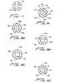
- FIGS 9A, 9B, 9C and 10Alternative lumen configurations spaced circumferentially are illustrated in Figures 9A, 9B, 9C and 10 .
- Figure 9Bthree arc-shaped lumens 60a, 60b, 60c are positioned around the arterial central lumen 40'. These larger sized lumens provide for additional venous flow but result in the reduction of the strength of the catheter wall due to the less wall material as compared to the lumen configuration of Figure 8 .
- Figure 9Afive lumens 66a, 66b and 66c are provided. These lumens have more of a rectangular (or trapezoidal) shape with one pair of opposing walls having a straighter configuration than the lumen configuration of Figure 8 . As shown, the other pair of opposing walls has a slight curvature.
- FIG 9Cfour oval-like venous lumens 76a, 76b, 76c and 76d are positioned around a substantially square central lumen 78.
- This lumen configurationprovides for a substantially sized central lumen and sufficient room between the central lumen 78 and each of the venous lumens 76a-76d for the catheter walls to flex.
- five lumens 70a-70e of circular cross-sectionare provided around the central lumen 40", adding to the stability of the catheter by increasing the wall material, but reducing the overall venous lumen size as compared to the embodiment of Figure 8 .
- the venous lumens in each of these embodimentsare independent from one another along the substantial length of the catheter.
- lumens of other configurationsare also contemplated.
- This positioning of the venous lumens in a circle-like array around the catheter, i.e. radially displaced from the center of the cathetermore evenly distributes the vacuum, as compared to a side by side venous/arterial lumen configuration, and ensures constant return flow since if one of the lumens becomes stuck against the vessel wall or otherwise clogged, the remaining lumens will maintain adequate flow.
- the openings in the sidewalls communicating with the lumenscan also be elongated instead of circular, creating a series of longitudinally extending openings for entry of suctioned blood. This version of elongated openings is shown for example in Figures 18 and 20 described in detail below.
- the catheteris configured to receive a stiffening member in the form of a stiffening rod which stretches the catheter to reduce its profile to aid in over the wire insertion and better navigate through small vessels. That is, the stiffening rod is inserted into central lumen 40 of catheter 10 and torqued to stiffen the flexible catheter for ease in over the wire insertion and navigation through the small vessels, and to reduce the outer diameter of the catheter body by stretching it during insertion. After placement of the catheter 10, the stiffening rod is removed, allowing the catheter to return to its higher profile position with the lumens of the necessary size for blood transport to and from the body. Two embodiments of the stiffening rods are illustrated in Figures 4A and 4B and are shown prior to insertion into the catheter 10 in Figure 3 .
- the stiffening rod 80is designated generally by reference numeral 80.
- Stiffening rod 80has a distal tip 82, a proximal end portion 85 and an internal lumen 87 extending therethrough (see Fig. 11 ).
- Stiffening rod 80is inserted through the proximal end of inflow tube 16, in the direction of the arrow of Figure 11 , over the guidewire 20 (which extends through lumen 87 and through central lumen 40 until distal tip 82 abuts shoulder or stop 43 as shown in Figure 12 .
- the proximal end portion 85 of stiffening rod 80has a threaded portion 81 which is screwed onto screw thread 15 of inflow tube 16.
- This threaded mountingrequires the stiffening rod 80 to be manually twisted, thereby torquing rod 80 as it presses forwardly and applies a force against shoulder (abutment surface) 43 to stretch the catheter body 11 to reduce its outer diameter.
- the catheter body 11can be reduced in diameter from about .215 millimeters to about .207 millimeters by the stiffening rod 80. (Other size reductions are also contemplated).
- This reduction in catheter body diameter or profileis represented by the arrows D1 and D2 in Figures 11 and 12 , respectively, which show the change in dimension effectuated by the stiffener rod 80.
- the stiffening rod 80is unthreaded from the proximal thread 15 of inflow tube 16 and removed from the central lumen 40 of the catheter 10 and from the inflow tube 16, thereby allowing the catheter to return to its normal profile of Figure 11 .
- stiffening rod 80can alternatively be temporarily attached at its proximal end to the inflow tube 16 by other means such as a bayonet lock, snap fit, etc. The rod could first be manually twisted and then mounted by these various means for retention in its torqued position.
- Stiffening rod 90has a threaded distal end 92 which is threaded onto internal threads 251 of catheter 200 shown in Figure 6B .
- a series of proximal threads 91are screwed onto the threads 15 of the inflow tube 16 in the same manner as described above for stiffener rod 80.
- the stiffening rod 90functions in the same manner as stiffening rod 80, i.e. to stretch the catheter during insertion to reduce its profile and to stiffen it to facilitate insertion, the only difference being the mechanical threaded attachment of the distal end of the stiffening rod 90 to the catheter 200 instead of the abutting relation of stiffening rod 80 with shoulder 43 of catheter 10.
- the distal threads 92are first threaded onto internal thread 251, followed by attachment of the proximal threads 91 as the stiffening rod 90 is torqued.
- Stiffening rod 90like stiffening rod 80, is preferably circular in cross-section, although other configurations are also contemplated.
- Catheter 200 of Figure 6Bis identical to catheter 200 in all respects except for the threads 251 instead of shoulder 43 and lumen 241 which is uniform in diameter. Similar to catheter 10, catheter 200 has distal opening 247 and outflow side openings 246 in outer wall 244 communicating with lumen 241 in distal tip portion 242, which communicates with central lumen 40. Venous inflow lumens 234a-234e terminate at wall 248 and have respective side openings 252a-252e and 250s-250e formed in the outer wall 214. Only one of the side openings 250a, 252a are shown in the longitudinal cross-sectional view of Figure 6B .
- distal tipcan be composed of a different stiffer material than the catheter body 11 or can be composed of a material having a higher durometer than the catheter body. This stiffer material will facilitate both tunneling through and dilating tissue. In an alternate preferred embodiment, however, the distal tip is composed of the same material as the catheter body but has a stiffening insert.
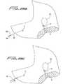
- the alternative nose (tip) configurationis illustrated in Figure 15 , with the method of manufacturing the tip shown in Figures 13 and 14 .
- This nose or distal tip 104is composed of the same material as the catheter body 108 and has a stiffening insert 110 inserted through central lumen 106 of nose 104. Central lumen 106 extends through the catheter body.
- the stiffening insert 110is preferably composed of the same material as the catheter body 11 and nose 104, except it is made of a harder durometer material such as 72 shoreD vs. 85 shoreA for the catheter body 11.
- the material utilizedcan be, by way of example, urethane. For convenience, only the distal tip is shown, the remaining portions of the catheter 100 being identical to catheter 10.
- the stiffening insert 110preferably cylindrical as shown, has a hole 112 for receipt of the guidewire and for communication with central lumen 106. Insert 110 engages the inner wall surface 114 of central lumen 106. Lumen 106, proximal of side openings 119, will include either a stepped portion to provide an abutment surface (shoulder) for stiffening rod 80 or internal threads to mount stiffening rod 90 as described above.
- stiffening insert 110is placed within central lumen 106 at the distalmost end and substantially flush with the distalmost edge 102 of the cylindrical tube.
- the tubeis formed into the bullet nose shape of Figures 15A and 15B , by a conventional radiofrequency or other heating process which allows the tip material to flow and form around the harder insert 110.
- the materialis cooled and thereby hardens to the configuration of Figure 15 as the material fuses to the insert 110.
- a conventional core pin(not shown) can be used, inserted through the hole 112 and central lumen 106 during the forming process. When the material hardens, the pin is withdrawn to maintain these openings.
- side holes 114are either cut or drilled through the wall 108 of catheter 100 to communicate with lumen 106 in the same manner as side holes 46 communicate with central lumen 40 of Figures 1-6 .
- FIGS 16A-17Cillustrate two alternate embodiments of the catheter of the present invention having spacers to minimize contact of the catheter body with the vessel wall. Provision of these spacers is optional.
- catheter 150similar to catheter I0, has a distal portion having a nose 154, a central arterial lumen 156 which also receives a guidewire 20, and a series (e.g. 5) of venous lumens 160 - 160.
- Arterial lumen 156communicates with lumen 151 1 and narrowed lumen 153 of the nose 154, terminating in open distal end 158.
- a plurality of side openings 159communicate with lumen 151 and function in the same manner as side openings 46 of catheter 10.
- Venous lumens 160each terminate at side openings 161, similar to side openings 52 of venous lumens 34 of catheter 10. Although only one series of side openings 161 are shown, clearly additional arrays of side openings, positioned distally or proximally of side openings 161 could be provided.
- the venous lumen configurationcan also vary in a similar manner as described above with respect to catheter 10. Thus, except for the spacers, catheter 150 is identical to catheter 10.
- a plurality of spacer wires 164are embedded in the wall 169 of the catheter 150 and are secured at region 158 by adhesive or other suitable means. In the normal configuration, spacer wires 164 bow slightly outwardly with respect to the outer wall 169 of the catheter 150 to reduce the likelihood of contact with the vessel wall.
- the stiffening rod 80is inserted over guidewire 20 and through central lumen 156, as shown in Figure 16C , and edge 170 is forced against the abutment surface or stop 159, the catheter body is stretched and the spacer wires 164 stretch to a straightened position, substantially flush with the outer surface of wall 169. This reduces the profile of the catheter and ensures the spacer wires do not interfere with catheter insertion.
- stiffening rod 90can also be used with catheter 150 and would function to reduce the profile in the same manner as rod 80. Catheter 150 would then be provided with internal threads for mounting stiffening rod 90 as described above.
- Catheter 180is identical to catheter 150, except it is provided with integral ribs 194 proximal of nose 184. That is, similar to catheter 150, catheter 180 has a central arterial lumen 186 configured to receive guidewire 20 and stiffening rod 80 or 90. Lumen 186 communicates with lumen 181 and narrowed lumen 183 of the nose 184 which terminates in open distal end 188. Side openings 189 of nose 184 communicate with lumen 181. A series of independent venous lumens 190 are provided, terminating in side openings 192, similar to side openings 161 of catheter 150. Although only one series of side openings 192 are shown, clearly additional arrays, positioned proximally or distally of side openings 192 could be provided.
- Spacer ribs 194are formed by cutout portions in the wall 193 of the catheter 150.
- Figure 17Billustrates the spacer ribs 194 in their normal position, outwardly bowed from the outer surface of the wall 193 of the catheter body.
- Figure 17Cillustrates the straightened or retracted position of the spacer ribs 194, where the ribs 194 are substantially flush with the outer surface of wall 193, after stiffener rod 80 of Figure 4A (or rod 90 of Figure 4B )) is inserted through central lumen 186 to stretch the catheter 150 for insertion in the manner described above.
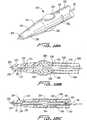
- FIGS 18 and 19illustrate another alternative embodiment of the catheter of the present invention.
- Catheter 500has a distal tip 502 with a tapered region 510 transitioning to a reduced diameter region 504.
- the central lumenterminates in distal opening 506 for fluid delivery.
- the distal opening 506is the sole fluid delivery passageway into the body.
- additional side holescould be provided in the tip to provide additional arterial ports for blood delivery to the patient.
- a series of venous openings 508are provided in the transition or tapered region 510 of the tip 502. These openings are elongated to provide additional area for suctioning. Each of the openings 508 communicates with a respective venous lumen 510 formed in the catheter.
- the venous lumen configuration(and arterial lumen configuration) can be in the form of those illustrated in Figures 7-10 , or other variations, as described above.
- Stiffening rod 520is shown positioned in the central lumen of the catheter 500.
- Rod 520is similar to the rods 80 and 90 described above except it extends distally of the distal tip 502 of catheter 500, has a tapered distal end 524 to facilitate tunneling and dilating tissue, and has a stepped portion to abut the internal structure of the catheter 500.
- guidewire 20is shown extending through the central lumen of stiffening rod 520.
- the stiffening rod 520is inserted through the central lumen of catheter 500 and the stiffening rod 520 and catheter 500 are inserted over the guidewire 20, with the tapered tip 524 facilitating passage of the catheter as it dilates tissue.
- Catheter 500has a cylindrical insert 514 positioned in the distal tip, similar to insert 110 of Figure 13A .
- the insert 514is composed of a stiffer material to stiffen the tip of the catheter 500 to facilitate insertion.
- Insert 514has an opening to receive stiffening rod 520 as shown.
- Shoulder 526 formed by stepped portion 524abuts the insert 514, thereby functioning as a stop in a similar manner that shoulder 43 acts as a stop for stiffening rod 80 shown in Figure 11 , the difference being the shoulder is formed in the internal wall of the catheter rather than on the stiffening rod.
- Stiffening rod 520thus acts in the manner as the aforedescribed rods 80, 90, i.e. pressing against the catheter tip portion to stretch the catheter for insertion, in addition to providing a tissue tunneling and dilation function.
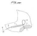
- FIG 20illustrates an alternative tip design of the catheter of the present invention.
- Catheter tip 602has a bullet nose configuration, somewhat similar to the nose of Figure 15 , except having more of a progressive taper.
- Catheter tip 602also has a. series of elongated venous holes 608 (only two are shown in the view of Figure 20).
- catheter 600is identical to catheter 500 of Figure 18 .
- Trocar 300has a lumen 304 formed thererethrough (shown in phantom in Figure 22 ) dimensioned for reception of guidewire 20.
- the lumen 304extends the entire length of trocar 300, from a proximal opening 306 in handle 308 to a distal opening 310 (shown in phantom in Figure 22 ) on the underside of the trocar 300 as viewed in Figure 22 .
- Distal opening 310is adjacent the distal tip 302, at the region where it bends slightly upwardly.
- trocar 300can be smaller than the outer diameter of the dialysis catheter, e.g. catheter 10, since it only needs to have an internal diameter of about 1,14 mm (.045 inches) to receive the guidewire.
- the diameter of the catheteris typically 5.46 mm (.215 inches).
- the blunt distal tip 302 of trocar 300bluntly dissects tissue to create a subcutaneous tissue tunnel for subsequent securement of the catheter.
- FIGS 24A and 24Billustrate an alternate embodiment of the trocar.
- Trocar 380is similar to trocar 300 except for an elongated oval entrance opening 382 to lumen 383 for the guidewire and a beveled tip 384 to facilitate tunneling through tissue.
- the handle configuration 386is also slightly different.
- needle "N”is inserted into the internal jugular vein to properly locate the vessel and a guidewire 20 is inserted through the needle into the right internal jugular vein “a” and into the superior vena cava “b” as shown in Figure 25 .
- the guidewire 20is further advanced into the right atrium “c”.
- the needle 'N”is then withdrawn, leaving the guidewire 20 in place, extending out of the patient's body at the proximal portion 21.
- trocar 300is inserted through a first incision "s" in the patient, bluntly dissecting and tunneling under the skin, and forced out of the tissue at a second incision or site "u", creating a subcutaneous tunnel “t” under the tissue as shown in Figure 27 .
- Thisprovides a way to secure the catheter as described below.
- Guidewire 20is then threaded through lumen 304 of the trocar, with proximal portion 21 first inserted through trocar distal opening 310 so it emerges out of proximal opening 306 as shown in Figure 28A .
- Trocar 300is then withdrawn from the body in the direction of the arrow of Figure 28B , leaving the guidewire 20 in place as shown.
- guidewire 20extends from the right atrium and superior vena cava, out through the right internal jugular vein and through the tissue tunnel "t".
- Catheter 10is then threaded over the guidewire 20, with the proximal portion 21 of the guidewire 21 inserted through the distal tip lumen of the catheter, through the length of the central lumen, and through the hub 12 into the inflow tube 116 and out through fitting 15.
- the catheter 10is thus threaded over the wire, through the tissue tunnel "t" where cuff 36 (not shown in Figure 28C ) is positioned in the tissue tunnel "t” to aid in securement of the catheter by enabling tissue ingrowth over a period of time.
- the catheter 10is further advanced over guidewire 20 down into the right internal jugular vein, into the superior vena cava, and into the right atrium.
- the guidewire 20is withdrawn in the direction of the arrow, leaving the catheter 10 in place for use as shown in Figure 28C .
- the stiffening member 80 or 90(not shown in Figure 28C for clarity) is preferably utilized, i.e. inserted over the guidewire 20 through the fitting 15, inflow tube 16, hub 12, and central lumen 40 to help guide the catheter 10 as described in detail above.
- the catheterwill be inserted in a similar fashion through the left internal jugular vein to be positioned as depicted in Figure 2 .
- the subcutaneous tissue tunnelwill be formed on the left side as shown in Figure 2 , by the trocar 300, and the catheter inserted over the guidewire through the subcutaneous tissue tunnel and through the left internal jugular vein and into the superior vena cava and right atrium in the same way as described for right side insertion.
- any of the aforedescribed catheters of the present inventioncan be inserted in this fashion.
- FIG. 29A-29GAn alternative method of insertion is illustrated in Figures 29A-29G .
- this methodinstead of forming a second incision site adjacent the incision site through which the needle and guidewire are introduced into the internal jugular vein as in Figure 27 , the trocar 300 emerges from the needle/guidewire insertion site.
- catheter 10is shown, any of the foregoing catheters can be inserted in the same manner.
- the needle and guidewireare inserted in an identical manner as illustrated in Figures 25 and 26 .
- the guidewire 20is left in place extending outwardly from the incision site, designated by "w".
- trocar 300is inserted through a first incision (as in Figure 27 ) to create a subcutaneous tissue tunnel; however, unlike Figure 27 , trocar 300 does not emerge at a second incision site "u”. Instead, trocar 300 is advanced subcutaneously to the needle incision site "w", and emerges through the site "w” as shown.
- the distal end of trocar 300'exits incision site "w" alongside the guidewire 20.
- Guidewire 20is then inserted (threaded) through the opening in trocar 300 as described above and then the trocar is withdrawn through the tissue tunnel 't" and out through the first incision "s", pulling the guidewire 20 through the tunnel.
- the trocar 300is removed as shown in Figure 29B , leaving the guidewire 20 in place.
- the guidewire 20is positioned to form a guidewire loop 22 to facilitate insertion of the catheter as will be described below.
- the catheter 10is then advanced over the guidewire 20 ( Figure 29C ), through the tissue tunnel, and exiting incision site "w" into the internal jugular vein "a" ( Fig. 29D ).
- the catheter 10, as shown,is formed into a loop 13, tracking the loop 22 of guidewire 20, and then advanced downwardly through the internal jugular vein, the superior vena cava and into the right atrium. ( Figure 29E ).
- the guidewire 20is then withdrawn as shown in Figure 29F , and the catheter 10 is pushed downwardly and/or pulled back to straighten the loop to position the catheter as shown in Figure 29G .
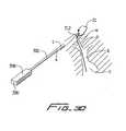
- FIG 30shows an alternate embodiment of a trocar utilized to retrieve the suture and retract it through the subcutaneous tissue tunnel.
- Trocar 300'is similar to trocar 300 of Figure 29 except for the provision of eyelet 312.
- the sutureis threaded through the eyelet (shown as two small opposing holes in the wall at the distal end of the trocar 300') and the trocar is pulled proximally through the tissue tunnel to pull the suture out through incision "s".
- the trocarextends through incision "w", the same incision created for insertion of the needle and guidewire.
- a hook or other meanscan be provided on the trocar for holding the guidewire to enable pulling the guidewire through the tissue tunnel. That is, in these versions, the guidewire is not threaded through the trocar lumen, but rather the trocar is utilized to pull (retract) the guidewire through the tissue tunnel.
- FIG 21illustrates an alternative trocar used for a different approach to catheter insertion.
- This trocardesignated by reference numeral 350, does not provide for an entire over the wire system, however it is used with an approach providing a partial over the wire system which eliminates the need for a tear way introducer sheath.
- tear away introducer sheathsare currently being utilized to guide the dialysis catheter through the vessels into the right atrium.
- the catheter in this alternate methodcan be advanced over a guidewire which can be placed in the manner illustrated in Figures 25 and 26 .
- trocar 350is attached to the distal end of the catheter by insertion of barbed end 352 into a mating fitting.
- Other means for temporarily attaching the trocarare also contemplated.
- Trocar 350has a blunt distal tip 354 and is advanced through a first tissue incision and out through a second tissue incision, bluntly dissecting tissue and forming a subcutaneous tissue tunnel in a similar manner as described above, except without the guidewire. Since trocar 350 is attached to the catheter, it pulls the catheter through the tissue tunnel, so it emerges out through the second incision. The trocar 350 is then detached from the catheter. The catheter is then bent as necessary and threaded over the guidewire into jugular vein, superior vena cava, and right atrium.
- a methodwhich enables connection of the central arterial (delivery) lumen of the catheter with an inflow tube and fluid connection of the five independent venous (withdrawal) lumens with a single outflow tube to provide fluid connection through the connectors.
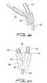
- a longitudinal slit 201is formed at a proximal portion of catheter tube 203.
- Figure 32shows the relationship of the slit 201 and the central arterial lumen 205 as the slit is formed to communicate with the central lumen 205.
- the slit 201is formed in the wall 206 of the catheter tube 203 between adjacent venous (withdrawal) lumens 209a-209e.
- a metal pin 207is inserted through the slit 201 for the molding process.
- Outer plastic inflow tubing 210is placed over the metal pin 207 as shown in Figure 35 to ultimately communicate with the central lumen 205.
- Outer plastic outflow tubing 211is also shown positioned over the catheter tube 203 which will communicate with the venous lumens 209.
- Lumen 204has a narrowed region 202. As shown in Figure 37 , lumen 204 fluidly connects lumen 207 of inflow tube 210 with the central lumen 205 of the catheter. Lumen 212 of outflow tubing 211 communicates with the five independent venous lumens 209.
- Figures 38-39illustrate another method for manufacturing the catheter connections.
- catheter body 402 of catheter 400is separated into five segments 401a-401e at its proximalmost end, corresponding to each of the venous (withdrawal) lumens 403a-403e.
- Figure 40illustrates the five cuts 408 made in the catheter wall 407 between the adjacent venous lumens 403 to form the five segments 401.
- a separate outflow connector tube 412a-412eis positioned within a respective venous lumen 403a-403e and is connected to a respective segment 401a-401e by solvent bonding or pressure fit.
- the proximal end of each connector tube 412is positioned within outflow tube 414 which transports blood to the dialysis machine.
- bloodflows through the venous lumens 403, through each outflow connector tube 401 and into a single outflow tube 414.
- Inflow tubing 416is connected to central arterial lumen by inflow connector tube 410 which is attached inside the arterial lumen by solvent bonding or pressure fit. Note that inflow connector tube 410 is positioned between the segments 401. It should be understood, that if fewer or larger number of venous lumens are provided, then an equal amount of outflow tubes would be utilized as the venous lumens would be cut into the corresponding number of segments.
- Figures 41-43illustrate another alternate method for manufacturing the hub of the catheter of the present invention.
- This hub and associated tubingis illustrated for use with a catheter having the lumen configuration of Figure 9C , although it can be utilized with other lumen configurations as well.
- a central lumen connector (intermediate) tube 702is joined with central lumen 78 of catheter 700.
- Four venous connecting (intermediate) tubes 704are connected to a respective venous lumen 76a. These tubes each have a lumen that is substantially circular in cross-section along its length.
- the substantially circular lumenscorresponds to the cross-sectional shape of the venous lumens within catheter 10 which transition from a substantially oval cross-sectional configuration to a substantially circular cross-sectional configuration at the flared proximal portion shown in Figure 43 .
- arterial lumen 78also transitions to a substantially circular cross-sectional configuration.
- Each of the connector tubes 704is connected to multi-lumen extension (outflow) tube 708 which provides outflow of blood to the dialysis machine.
- Extension tube 708has a flared distal portion 711 with four lumens 710, each configured for communicating with one of the connector tubes 704.
- each of the lumens 710has a substantially circular cross-sectional configuration that transitions to a substantially triangular cross-sectional configuration towards the proximal portion.
- Single lumen extension (inflow) tube 712which provides inflow of blood to the patient, connects to connector tube 702.
- Extension tube 712has a tapered distal end 718 and its lumen 719 transitions from a substantially circular cross-sectional configuration to a substantially square configuration toward the proximal end. Molding of housing 716 with the foregoing tubes forms the catheter hub.
- Conventional tube clamps, such as clamps 17 and 19 of Figure 1are placed around extension tubes 708, 712 for cutting off blood flow.
- a rotatable suture ring 720is placed around the catheter hub and preferably has a planar surface 722 to sit substantially flush with the patient's skin. Suture holes 724 are configured to receive sutures for attaching the ring (and thus the catheter) to the patient.
- the catheters described abovecan optionally include a surface treatment on the exterior and/or the interior.
- the surface treatmentscan include for example, an hydrophilic coating to increase lubricity and facilitate insertion, a drug coating such as heparin or containing IIb, IIIa inhibitors, inert coating substances such as Sorins carbon coating, and/or active coatings such as a silver ion coating.
- catheteris described herein as a dialysis catheter for hemodialysis, the catheter disclosed herein could have other surgical applications, such as drug delivery or blood sampling. Moreover, features of the catheter, tip configurations and lumen configurations can be utilized on other catheters.
Landscapes
- Health & Medical Sciences (AREA)
- Life Sciences & Earth Sciences (AREA)
- Heart & Thoracic Surgery (AREA)
- Hematology (AREA)
- Public Health (AREA)
- Anesthesiology (AREA)
- Biomedical Technology (AREA)
- Engineering & Computer Science (AREA)
- Veterinary Medicine (AREA)
- Animal Behavior & Ethology (AREA)
- General Health & Medical Sciences (AREA)
- Pulmonology (AREA)
- Biophysics (AREA)
- Urology & Nephrology (AREA)
- Vascular Medicine (AREA)
- Emergency Medicine (AREA)
- Cardiology (AREA)
- Media Introduction/Drainage Providing Device (AREA)
- External Artificial Organs (AREA)
Description
- This application relates to a catheter and more particularly to a multi-lumen catheter which facilitates hemodiaylsis.
- Hemodialysis is a well known method of providing renal (kidney) function by circulating blood. The kidneys are organs which function to extract water and urea, mineral salts, toxins, and other waste products from the blood with filtering units called nephrons. From the nephrons the collected waste is sent to the bladder for excretion. For patients having one or both defective kidneys, the hemodialysis procedure is life saving because it provides a machine to simulate the function of the kidneys.
- In the hemodialysis procedure, blood is withdrawn from the patient's body through a catheter or tube and transported to a dialysis machine, also commonly referred to as a kidney machine. The catheter is typically inserted through the jugular vein and maneuvered into position through the superior vena cava into the right atrium to provide high blood flow. In the dialysis machine, toxins and other waste products diffuse through a semi-permeable membrane into a dialysis fluid closely matching the chemical composition of the blood. The filtered blood, i.e. with the waste products removed, is then returned to the patient's body. In some instances, the catheter may be left in place for several years. As can be appreciated, proper access to the patient's blood and transport of the blood to and from the dialysis machine for this extended period of time is critical to hemodialysis.
- One example of a dialysis catheter currently being marketed is the MedComp Ash Split catheter. This catheter has two lumens, one for arterial flow and the other for venous flow, which are each D-shaped in cross-sectional configuration. The catheter is bifurcated at its distal end to separate the lumens and the catheter is manually split to the desired length for selected separation before insertion into the target area. Another well-known catheter is a Med Comp catheter which has the venous flow lumen terminating proximally, i.e.. axially recessed, from the arterial flow lumen. Each of these lumens is also D-shaped in cross-sectional configuration.
- These Medcomp dialysis catheters require numerous steps for insertion. The multiple insertion steps can be summarized as follows:
- 1. an introducer needle is inserted through a first incision site (first opening) to properly locate (access) the vessel, e.g. the right internal jugular vein;
- 2. a guide wire is inserted through the needle into the internal jugular vein and down through the superior vena cava into the inferior vena cava;
- 3. the introducer needle is withdrawn leaving the guidewire in place;
- 4. a tear away (peel away) sheath and dilator are inserted over the guidewire and through the first incision site to provide an access port for the dialysis catheter into the jugular vein, superior vena cava and right atrium;
- 5. a second incision is made in the chest wall to create a second opening;
- 6. a trocar is attached to the distal end of the dialysis catheter;
- 7. the trocar and dialysis catheter are pushed through the second incision and advanced to bluntly dissect the subcutaneous-tissue to exit the first incision (opening) which was created by the introducer needle, thereby creating a subcutaneous tissue tunnel between the first and second openings;
- 8. the trocar is detached from the dialysis catheter leaving the catheter in place extending from the second opening, through the tissue tunnel and out the first opening;
- 9. the dilator and guidewire are removed, leaving the tear away sheath in place in the first incision which has been expanded by the dilator;
- 10. the dialysis catheter, which is protruding from the first incision, is inserted through the tear away sheath and advanced so its distal portion is positioned in the right atrium;
- 11. the sheath is separated, i.e. split, by pulling the tabs apart, and then pulled upwardly away from the dialysis catheter and removed from the body, leaving the catheter in place; and
- 12. the second incision is closed and the dialysis catheter, which is connected through tubes to the dialysis machine, is left in place an extended period of time to provide blood circulation to and from the dialysis machine.
- (Alternatively, in the foregoing method, the trocar can be forced through a third incision exiting adjacent the first incision, and then inserted through the introducer sheath positioned in the first incision.)
- This multiple step process of inserting the Medcomp dialysis catheter is time consuming and complicates the surgical procedure. These multiple steps add to the cost of the procedure, not only because of the additional surgeon's time but because additional components, such as the tear-away sheath, are required which increases the overall cost of the catheter system. Also, removal of the dilator increases the tendency of the sheath to kink causing difficulties in catheter insertion.
- The use of the tear away sheath is also potentially problematic. The tear-away style sheath has lines of weakness to separate the sheath as it is pulled apart by the pull tabs to enable removal of the sheath. However, the sheath can potentially cause damage to the vessel wall as it is being pulled apart and can cause, infection. Moreover, pulling the sheath laterally can enlarge the incision, thereby increasing the difficulty of closing the incision at the end of the procedure. Also, since the sheath is pulled in the proximal direction for removal, it could pull the catheter proximally as well, thereby pulling it away from the desired site, and requiring repositioning. The edges of the tear away can also lacerate the surgeon's glove and finger.
- An additional potential risk with utilizing tear away sheaths is that air embolism can occur. During the time the surgeon withdraws the dilator from the sheath and inserts the catheter, a passageway through the sheath to the vessel is open. If the patient inhales during this catheter exchange, an air bubble can enter the vascular system and obstruct the vessel, potentially causing stroke or even death.
- It would therefore be advantageous if a dialysis catheter insertion method could be provided which reduces some of the foregoing procedural steps, thereby decreasing the complexity of the procedure and decreasing the hospital and surgeon costs. It would also be advantageous if such dialysis catheter insertion method could be provided which would be less traumatic and avoid the foregoing problems associated with the use of a tear-away sheath, such as increased risk of air embolism, trauma to the vessel wall, incision enlargement and dislodgement of the catheter.
- Another area of dialysis catheter insertion, which needs improvement, is guiding the catheter to the target site. Dialysis catheters are composed of flexible tubing to minimize damage to the vessel wall during insertion and use. This flexibility, however, oftentimes results in kinking of the catheter since the catheter must navigate curves to reach the target vessel. This kinking can adversely affect blood flow. Also, the catheter needs to have some degree of stiffness to enable directing the catheter around the curves of the vessels. The stiffness, however provides its own risks since if the catheter is not properly directed, the catheter can inadvertently be forced against the vessel wall, thereby puncturing or damaging the vessel. Several different approaches have been discussed in the prior art to increase stiffness of catheters such as providing a distal tip of stiffer material to guide the catheter as in
U.S. Patent No. 5,957,893 , using materials of different durometers in various portions of the catheter (U.S. Patent No. 5,348,536 ), placing an additional concentration of material in the tip as inU.S. Patent No. 4,583,968 , or providing reinforcing strips, obturators or tubes within the catheter body to increase the rigidity (e.g.U.S. Patent Nos. 4,619,643 ,4,950,259 5,221,255 ,5,221,256 , and5,246,430 ). The need however exists to improve the balance between flexibility and stiffness. Thus it would be advantageous to provide a catheter with sufficient flexibility to accommodate anatomical curves of the patient while still having sufficient stiffness to enable guiding the flexible catheter tubing atraumatically through the length of the vessels. - In navigating vessels to access the target site, such as the right atrium, it is desirable to provide the smallest catheter profile, i.e. the smallest outer diameter catheter body. This profile facilitates insertion through smaller vessels as it reduces the likelihood of the catheter engaging the wall of the vessel and reduces trauma to the vessel by minimizing frictional contact with the vessel wall. However, the desire for smaller diameter catheters must be balanced against the need for providing sufficient sized lumens to enable proper blood flow. If the lumens are too small, sufficient blood flow may not be able to be maintained and the blood can be damaged during transport. Also, a sufficient relationship must be maintained between the size of the lumens and the overall diameter of the catheter to maintain the structural integrity of the catheter.
- Numerous attempts have been made in the prior art to optimize the multi-lumen configuration. In some approaches, such as disclosed in
U.S. Patent Nos. 4,568,329 and5,053,023 , inflow and outflow lumen are provided side by side in D-shaped form. In other approaches, such as those disclosed inU.S. Patent Nos. 4,493,696 ,5,167,623 and5,380,276 the inflow and outflow tubes are placed in concentric relation. A catheter for even distribution of therapeutic fluids is disclosed inUS 5 021 044 . Said catheter has a central lumen and four longitudinally extending lumens for discharging said fluid, last said lumens being positioned radially of said central lumen. The central lumen accomodates a guidewire. Other examples of different lumen configurations are disclosed inU.S. Patent Nos. 5,221,256 ,5,364,344 , and5,451,206 . The lumen configuration must accommodate two competing factors: keeping the catheter as small as possible to facilitate insertion while keeping the lumens as large as possible for blood flow. This balance must be achieved while maintaining the structural integrity of the catheter. It would therefore be advantageous to provide a catheter which reaches an optimum compromise between these two competing factors. - Another important feature of dialysis catheters is the suction openings to withdraw blood. Keeping the suction openings clear of thrombolytic material and away from the vessel wall is clearly essential to dialysis function since an adequate supply of blood must be removed from the patient to be dialyzed. However, a problem with prior dialysis catheters is that during blood withdrawal, as suction is being applied through the catheter openings and lumen, the suction can cause the catheter to be forced against the side wall of the vessel, known as "side port occlusion", which can block the opening and adversely affect the function of the catheter by enabling only intermittent suction. In fact, the opening can become completely blocked, thereby preventing necessary intake of blood, i.e. venous flow. Fibrin sheath growth around the outside of the catheter can occur since dialysis catheters are oftentimes implanted for several months or even years. This fibrin growth, caused by the body's attempt to reject the catheter as a foreign body, could result in blocking of the suction holes.
- The need therefore exists for an improved dialysis catheter which facilitates the surgical dialysis procedure. Such catheter would advantageously reduce the catheter insertion time, simplify the catheter insertion process, eliminate the need for a peel-away introducer sheath, decrease the chances of infection, reduce unwanted kinking of the catheter during insertion, strike an optimal balance between overall catheter and lumen size, and improve the suction capability to avoid hampering of venous flow.
- The present invention overcomes the disadvantages and deficiencies of the prior art
- According to one aspect of the present invention there is provided a dialysis catheter comprising:
- a catheter body having a proximal portion, a distal portion, a first longitudinally extending central lumen configured to deliver blood, and at least three longitudinally extending lumens positioned radially of the first lumen, the at least three lumens configured to withdraw blood from a patient,
- at least one blood delivery opening formed in the distal portion of the catheter body, the at least one blood delivery opening being in fluid communication with the first lumen and configured for passage of blood therethrough; and
- at least three blood withdrawal openings formed in the outer wall of the catheter body, each of the blood withdrawal openings being in fluid communication with one of the at least three lumens and configured for passage of blood from a patient
- The at least three blood withdrawal openings may be spaced proximally of the at least one blood delivery opening
- The first lumen may be substantially rectangular in cross-section and each of the at least three longitudinally extending lumens may be substantially oval-like in cross-section.
- The cross-sectional configuration of the first lumen and of the at least three longitudinally extending lumens may each transition to a substantially circular cross-section at a proximal portion.
- A distal tip portion may be provided at the distal portion of the catheter body, the distal tip portion having a first stiffness greater than a second stiffness of an intermediate portion of the catheter body and being sufficiently rigid to dilate tissue as the catheter is inserted into a patient.
- The distal tip portion may have a stiffening insert positioned therein, the insert having a lumen formed therein communicating with the first lumen.
- The distal tip portion may taper to a reduced diameter region.
- The blood withdrawal openings may be elongated in an axial direction and may intersect a transverse plane of the catheter.
- The at least three blood withdrawal openings may form a first set of openings, and the catheter body may further comprise a second set of blood withdrawal openings, the second set of blood withdrawal openings second spaced proximally from the first set of openings.
- The distal portion of the catheter body may include an internal threaded portion to engage a stiffening member inserted through the first lumen to temporarily mount the stiffening member within the catheter.
- The distal tip portion of the catheter may include a shoulder adapted to abut a stiffening member inserted through the first lumen.
- The stiffening member may be removably positioned within the central lumen, the stiffening member removably mountable to the catheter and including a lumen for receiving a guidewire therethrough.
- A proximal portion of the stiffening member may have a series of threads for mounting the stiffening member to the catheter.
- The stiffening member may have an abutment surface for abutting a surface formed internally in the distal tip portion of the catheter body to limit insertion of the stiffening member.
- The present invention also relates to a system for placement of a dialysis catheter comprising a dilating trocar and a dialysis catheter, the system comprising:
- a) a trocar having an elongated tubular portion and a lumen extending longitudinally through the tubular portion, the tubular portion terminating in a dilating tip configured to dilate tissue and create a subcutaneous tissue tunnel, the lumen of the trocar having a first internal diameter and configured to removably receive a guidewire therethrough for retrieval of the guidewire; and
- b) a dialysis catheter as hereinbefore defined, at least a portion of the catheter having an outer diameter configured for insertion through the subcutaneous tissue runnel, one of the lumens of the catheter configured to receive the guidewire for over the wire insertion of the dialysis catheter through the tissue tunnel when the trocar is removed.
- An elongated opening may be formed in the trocar communicating with the lumen of the trocar for insertion of the guidewire.
- Preferred embodiment(s) of the present disclosure are described herein with reference to the drawings wherein:
Figure 1 is a plan view of a first embodiment of the multi-lumen catheter of the present invention being inserted through the right internal jugular vein and superior vena cava into the right atrium of a patient's body;Figure 2 is a plan view illustrating the multi-lumen catheter ofFigure 1 being inserted through the left internal jugular vein and superior vena cava into the right atrium;Figure 3 is an isometric view of the first embodiment of the multi-lumen catheter of the present invention and showing the direction of insertion of the stiffening rod;Figure 4A is a side view of a first embodiment of a stiffening rod of the present invention insertable through the catheter ofFigure 3 to facilitate catheter insertion;Figure 4B is a side view of an alternate embodiment of the stiffening rod of the present invention having a series of mounting threads at its distal end;Figure 5 is perspective view of the distal portion of the multi-lumen catheter ofFig. 3 and showing a guidewire extending through the central lumen;Figure 6A is a longitudinal cross-sectional view taken alonglines 6A-6A ofFig. 5 ;Figure 6B is a longitudinal cross-sectional view similar toFigure 6A except showing an alternate embodiment of the catheter having internal threads for securing the stiffening rod ofFigure 4B ;Figure 7 is a transverse cross sectional view taken along lines 7-7 ofFigure 6A ;Figure 8 is a transverse cross sectional view taken along lines 8-8 ofFigure 6A :Figure 9A is a transverse cross-sectional view similar toFigure 8 except showing a second alternate embodiment of the lumen configuration of the catheter of the present invention;Figure 9B is a transverse cross-sectional view similar toFigure 8 except showing a third embodiment of the lumen configuration of the catheter of the present invention;Figure 9C is a transverse cross-sectional view similar toFigure 8 except showing a fourth embodiment of the lumen configuration of the catheter of the present invention;Figure 10 is a transverse cross-sectional view similar toFigure 8 except showing a fifth embodiment of the lumen configuration of the catheter of the present invention;Figure 11 is a longitudinal cross sectional view of the distal end portion of the catheter ofFigure 3 illustrating the stiffening rod ofFigure 4A being inserted through the central lumen of the catheter;Figure 12 is a longitudinal cross sectional view similar toFigure 11 except showing the stiffening rod fully positioned within the central lumen, in abutment with the stop in the distal tip;Figures 13-15 illustrate an alternate embodiment of the distal tip of the catheter of the present invention and the method steps for forming the tip wherein:Figures 13A and 13B are perspective and cross-sectional views, respectively, of the tip before formation shown receiving a stiffening insert;Figures 14A and 14B are perspective and cross-sectional views, respectively, of the tip once the stiffening inserted has been placed therein;Figures 15A and 15B are perspective and cross-sectional views, respectively, of the distal tip formed into a bullet nose configuration and showing side holes formed therein;
Figure 16A is a perspective view of a distal portion of another alternate embodiment of the multi-lumen catheter of the present invention having a series of spacer wires and showing a guidewire extending therethrough;Figure 16B is a longitudinal cross-sectional view of the distal portion catheter ofFIG. 16A showing the spacer wires in the extended position;Figure 16C is a longitudinal cross-sectional view similar toFIG. 16A except showing the profile of the spacing wires and catheter body reduced as the stiffening rod ofFigure 4A is inserted into the central lumen over the guidewire to stretch the catheter during insertion;Figure 17A is a perspective view of a distal portion of yet another alternate embodiment of the catheter of the present invention having a series of integral spacer ribs;Figure 17B is a longitudinal cross-sectional view of the distal portion of catheter ofFIG. 17 showing the spacer ribs in the extended position;Figure 17C is a longitudinal cross-sectional view similar toFIG. 17A except showing the profile of the spacer ribs and catheter body reduced as the stiffening rod ofFigure 4A is inserted into the central lumen to stretch the catheter during insertion;Figure 18 is a perspective view of a distal portion of another alternate embodiment of the multi-lumen catheter of the present invention having a tapered tip;Figure 19 is a longitudinal cross-sectional view of the distal portion of the catheter ofFigure 18 showing the stiffening rod positioned through the central lumen of the catheter over the guidewire;- Figure 20 is a perspective view of a distal portion of yet another alternate embodiment of multi-lumen catheter of the present invention;
Figure 21 is a perspective view of a first embodiment of a trocar having a barbed proximal end for attachment to the catheter of the present invention for creating a subcutaneous tissue tunnel and for pulling the catheter through the tissue tunnel;Figure 22 illustrates an alternate embodiment of the trocar having a lumen for receiving a guidewire;Figure 23 illustrates the trocar ofFigure 22 being withdrawn after a subcutaneous tissue tunnel has been created;Figure 24A is a bottom view of another alternate embodiment of the trocar having a lumen for receiving a guidewire;Figure 24B is a longitudinal cross-sectional view of the distal end portion of the trocar ofFigure 24A ;Figures 25-28 illustrate the surgical method steps for inserting the multi-lumen catheter ofFigure 3 through the right internal jugular vein and superior vena cava into the right atrium wherein:Figure 25 shows the introducer needle being inserted through the right jugular vein and the guidewire being inserted through the right jugular vein, through the superior vena cava and into the right atrium;Figure 26 illustrates the needle introducer removed leaving the guidewire in place in the right internal jugular vein, superior vena cava and right atrium;Figure 27 illustrates the trocar ofFigure 22 being inserted through a first incision site and exiting a second incision site to create a subcutaneous tissue tunnel adjacent the incision site for the introducer needle;Figure 28A illustrates the guidewire being threaded through the lumen of the trocar ofFigure 22 ;Figure 28B illustrates the trocar being removed, leaving the guidewire in place extending through the tissue tunnel; andFigure 28C illustrates the multi-lumen catheter ofFigure 3 inserted over the guidewire through the tissue tunnel, and curved down into the right internal jugular vein, superior vena cava and right atrium;
Figures 29A-29G illustrate the steps for an alternate method of inserting the multi-lumen catheter ofFigure 3 through the right internal jugular vein and superior vena cava into the right atrium wherein the trocar creates a tissue tunnel with an exit opening at the incision cite where the needle and guidewire are introduced, wherein:Figure 29A illustrates the trocar ofFigure 22 inserted over the guidewire through a first incision site, creating a subcutaneous tissue tunnel, and exiting the incision site created for insertion of the introducer needle and guidewire;Figure 29B illustrates the trocar being removed, leaving the guidewire in place extending through the tissue tunnel and forming a loop adjacent the needle incision site; andFigure 29C illustrates the multi-lumen catheter ofFigure 3 being inserted over the guidewire for passage through the tissue tunnel;Figure 29D illustrates the catheter inserted through the subcutaneous tissue tunnel and forming a loop corresponding to the loop formed in the guidewire,Figure 29E illustrates the catheter extending through the subcutaneous tissue tunnel and being inserted further along the guidewire down into the right internal jugular vein;Figure 29F is a view similar toFigure 29E except showing the guidewire being removed; andFigure 29G illustrates the catheter in place extending through the subcutaneous tissue tunnel and advanced into the right internal jugular vein, superior vena cava and right atrium;
Figure 30 illustrates an alternate method of retracting the guidewire through the subcutaneous tissue tunnel formed by the trocar;Figures 31-37 illustrate a method for manufacturing a first embodiment of the hub of the multi-lumen catheter ofFigure 3 wherein:Figure 31 illustrates a slit formed in the outer wall of the catheter; .Figure 32 is a view similar toFigure 31 except showing in phantom the central arterial lumen of the catheter;Figure 33 is a transverse cross-sectional view taken along lines 33-33 ofFigure 32 ;Figure 34 illustrates a pin inserted through the slit in the outer wall of the catheter;Figure 35 illustrates the tubing inserted over the pin;Figure 36 illustrates the injection of soft material over the pin and catheter tube to form the catheter hub which retains the lumen connector tubes in position;Figure 37 illustrates the hub resulting from the injection molding process enabling one connector to communicate with the inflow (arterial) lumen and the other connector to communicate with the multiple outflow (venous) lumens;
Figures 38-40 illustrate an alternate embodiment of the hub of the multi-lumen catheter ofFigure 3 wherein;Figure 3 8 illustrates a perspective view of the proximal end of the catheter body split into five segments to accommodate the separate connector tubes;Figure 39 is a perspective view illustrating the connector tubes inserted into the respective lumens of the catheter body; andFigure 40 is a transverse cross-sectional view illustrating the cuts made in the catheter wall to form the separate segments.
Figure 41 is a perspective view of another alternate embodiment of the hub of the catheter of the present invention having the lumen configuration ofFigure 9C ;Figure 42 is an exploded view of the hub and tube structure ofFigure 41 ;Figure 43 is an enlarged perspective view showing the transition of the venous holes from a substantially oval to a substantially round configuration at the flared proximal portion of the catheter; andFigure 44 is an enlarged perspective view showing the multi-lumen extension tube tapering proximally and transitioning from substantially circular venous holes to substantially triangular holes.- Referring now in detail to the drawings where like reference numerals identify similar or like components throughout the several views, the first embodiment of the catheter of the present invention is designated generally by
reference numeral 10. Thecatheter 10 is typically inserted into an area of high velocity blood flow to ensure sufficient blood can be transported from the body for dialysis.Figure 1 illustrates thecatheter 10 inserted through the right internal jugular vein "a", into the superior vena cava "b", and into the right atrium "c";Figure 2 illustrates thecatheter 10 inserted into the left internal jugular vein "d", into the superior vena cava "b" and into the right atrium "c". Insertion into the right atrium, from either the right or left side provides the necessary high blood flow to the dialysis machine. Note that the catheter body (catheter tube) 11 is sufficiently flexible to enable it to bend to accommodate the anatomical curves as shown. Catheter 10 has a catheter body orcatheter tube 11 having adistal end portion 31, aproximal end portion 33, and anintermediate portion 35.Distal portion 31 terminates innose 42 which is illustratively substantially conical in shape.Proximal end portion 33 includeshub 12, where the lumens formed withincatheter tube 11 are connected, i.e. transition, to the respective inflow and outflow tubes, 16, 18, respectively, to enable return and withdrawal of blood for dialysis. Conventional tube clamps 17 and 19 cut off blood flow through inflow andoutflow tubes - As shown, intermediate portion of
catheter 10 extends through subcutaneous tissue tunnel "t", and curves downwardly toward the target site, e.g. the right atrium. This tunnel "t" secures the catheter in place for dialysis for a period of weeks, or even months, with fibrous cuff 36 (Figure 3 ) enabling tissue ingrowth. The formation of the tunnel "t" and the insertion of thecatheter 10 therethrough will be discussed below in conjunction with the discussion of the catheter insertion method. - It should be appreciated that although the catheter is shown emerging from the tissue tunnel "t" at a second incision site, preferably, the tissue tunnel would not have an exit opening at a second site but instead would exit through the same incision through which initial access is made by the needle and dilator into the internal jugular vein "a". This is described in more detail below.
- A series of lumens are formed in
catheter tube 11 for transporting blood to and from a dialysis machine. As is well known in the art, a dialysis machine essentially functions as a kidney for patients suffering from kidney failure. Blood is removed from the patient and transported to the dialysis machine where toxins are removed by diffusion through a semi-permeable membrane into a dialysis fluid. The filtered blood is then returned through the catheter body to the patient. - More specifically, and with reference to
Figures 5, 6A ,7 and 8 , details of the catheter lumens will now be described. Centrallongitudinal lumen 40 is formed withincatheter tube 11, extends the entire length and is designed to transport filtered blood to the patient.Lumen 40 is also configured to receive aguidewire 20 to direct the catheter to the desired position.Lumen 40 extends tonose 42, and terminates inregion 37 where it aligns with centrallongitudinal lumen 41 ofnose 42.Central lumen 41 ofnose 42 communicates with narrowedlumen 45, terminating indistal opening 47 to communicate with the patient's body so blood can be delivered throughdistal opening 47.Lumens guidewire 20. Thus,lumen 40,lumen 41 and narrowedlumen 45 together form a central lumen enabling blood to be delivered from the dialysis machine to the patient. The transition fromlumen 41 into narrowedlumen 45, forms a stop orshoulder 43, the function of which will be described below. Nose 42 also includes side arterial (delivery)openings 46 formed through theouter wall 44 wall in fluid communication withlumen 41, also functioning to return blood to the patient's body. Side openings orports 46 are preferably angled outwardly as shown to facilitate delivery of blood in the direction of blood flow and lessen mechanical hemolysis. These additional openings help maintain the desired flow volume by distributing the blood through multiple holes. Although only four openings are shown, it is contemplated that additional or fewer openings can be provided and the openings can be axially displaced with respect to each other. Additional set(s) of openings can also be provided spaced proximally or distally fromside openings 46.- In this embodiment,
nose 42 forms the distal tip portion and is composed of a different material than the other portions of thecatheter body 11 and is welded or attached by other means to thecatheter body 11. The tip (nose) in this embodiment is composed of a stiffer material to facilitate tunneling and blunt dissection through tissue. The nose could alternatively be composed of a softer material, thereby being less traumatic upon contact with the vessel wall. However, in a preferred embodiment, the nose is composed of the same material as the catheter body, having a small stiffener member embedded therein. This configuration is described in detail below in conjunction withFigures 13-15 . Catheter 10 also has a series of venous (withdrawal) lumens 34a -34e, extending longitudinally along the length of thecatheter body 11, each terminating atsurface 48 ofnose 42. In the preferred embodiment, shown in the cross-sectional view ofFigure 8 , the lumens 34 are oval-like in configuration, with oppositecurved walls flat walls catheter body 11. The lumens 34a-e are independent from one another through the distal, intermediate andproximal portions catheter body 11, until thehub 12 where the lumens 34a-34e connect to a common connector tube. This is described in more detail below. Lumens 34a-34e, as shown, are symmetrically positioned and radially displaced from the centralarterial lumen 40.- With continued reference to
Figures 5 and 6A , a series of side openings or ports 50 are provided in theouter wall 14 ofcatheter body 10. Theseopenings openings 52a-52e, spaced proximally fromopenings 50a-50e, is also in communication with a respective lumen 34a-34e. Only three of the side openings 50,52 are shown inFig. 5 , it being understood that the other three openings are positioned on the other side of the catheter, preferably symmetrically placed to accommodate the circumferential arrangement of the venous lumens 34a-34e. - Although lumens 34a-34e are isolated along a substantial length of the catheter, they preferably have a common flow source at the
proximal portion 33 of thecatheter 10. This is described in more detail below. - In the embodiment of
Figure 8 , the arterial lumen size preferably ranges from 1,52 mm (.006 inches) to about 2,03 mm (.008 inches) in cross-sectional area, and is more preferably 1,78 mm (.007 inches). The cross-sectional area of each of the venous lumens 34 preferably ranges from about 0,508 mm (.002 inches) to about 1,02 mm (.004 inches), and more preferably about 0,762 mm (.003 inches), bringing the total cross-sectional area of the venous return lumens to about 0,254 mm (.01 inches) to about 0,508 mm (.02 inches), and more preferably about 0,381 mm (.015). This means that the ratio of total cross sectional area of the arterial lumen to the venous lumen is about 1 to about 2.1. Other dimensions are also contemplated. - It should be appreciated that although five separate lumens 34 are shown, a fewer or greater number can be provided. Also, although two sets of side openings are shown (set 50 and set 52), a fewer or greater number of sets can be provided, and a fewer or greater number of openings in each set could be provided.
- Alternative lumen configurations spaced circumferentially are illustrated in
Figures 9A, 9B, 9C and 10 . InFigure 9B , three arc-shapedlumens Figure 8 . InFigure 9A , fivelumens Figure 8 . As shown, the other pair of opposing walls has a slight curvature. InFigure 9C , four oval-likevenous lumens central lumen 78. This lumen configuration provides for a substantially sized central lumen and sufficient room between thecentral lumen 78 and each of thevenous lumens 76a-76d for the catheter walls to flex. InFigure 10 , fivelumens 70a-70e of circular cross-section are provided around thecentral lumen 40", adding to the stability of the catheter by increasing the wall material, but reducing the overall venous lumen size as compared to the embodiment ofFigure 8 . Preferably, the venous lumens in each of these embodiments are independent from one another along the substantial length of the catheter. - Fewer or greater number of lumens could be provided and lumens of other configurations are also contemplated. This positioning of the venous lumens in a circle-like array around the catheter, i.e. radially displaced from the center of the catheter, more evenly distributes the vacuum, as compared to a side by side venous/arterial lumen configuration, and ensures constant return flow since if one of the lumens becomes stuck against the vessel wall or otherwise clogged, the remaining lumens will maintain adequate flow. The openings in the sidewalls communicating with the lumens can also be elongated instead of circular, creating a series of longitudinally extending openings for entry of suctioned blood. This version of elongated openings is shown for example in
Figures 18 and 20 described in detail below. - To facilitate insertion, the catheter is configured to receive a stiffening member in the form of a stiffening rod which stretches the catheter to reduce its profile to aid in over the wire insertion and better navigate through small vessels. That is, the stiffening rod is inserted into
central lumen 40 ofcatheter 10 and torqued to stiffen the flexible catheter for ease in over the wire insertion and navigation through the small vessels, and to reduce the outer diameter of the catheter body by stretching it during insertion. After placement of thecatheter 10, the stiffening rod is removed, allowing the catheter to return to its higher profile position with the lumens of the necessary size for blood transport to and from the body. Two embodiments of the stiffening rods are illustrated inFigures 4A and 4B and are shown prior to insertion into thecatheter 10 inFigure 3 . - Turning to the first embodiment of the stiffening rod illustrated in
Figure 4A , the stiffening rod is designated generally byreference numeral 80. Stiffeningrod 80 has adistal tip 82, aproximal end portion 85 and aninternal lumen 87 extending therethrough (seeFig. 11 ). Stiffeningrod 80 is inserted through the proximal end ofinflow tube 16, in the direction of the arrow ofFigure 11 , over the guidewire 20 (which extends throughlumen 87 and throughcentral lumen 40 untildistal tip 82 abuts shoulder or stop 43 as shown inFigure 12 . Theproximal end portion 85 of stiffeningrod 80 has a threadedportion 81 which is screwed ontoscrew thread 15 ofinflow tube 16. This temporarily secures the stiffeningrod 80 within thecatheter 10 during insertion. This threaded mounting requires the stiffeningrod 80 to be manually twisted, thereby torquingrod 80 as it presses forwardly and applies a force against shoulder (abutment surface) 43 to stretch thecatheter body 11 to reduce its outer diameter. It is contemplated in one embodiment, for example, that thecatheter body 11 can be reduced in diameter from about .215 millimeters to about .207 millimeters by the stiffeningrod 80. (Other size reductions are also contemplated).This reduction in catheter body diameter or profile is represented by the arrows D1 and D2 inFigures 11 and 12 , respectively, which show the change in dimension effectuated by thestiffener rod 80. - After the
catheter 10 is positioned at the desired site, the stiffeningrod 80 is unthreaded from theproximal thread 15 ofinflow tube 16 and removed from thecentral lumen 40 of thecatheter 10 and from theinflow tube 16, thereby allowing the catheter to return to its normal profile ofFigure 11 . - It should be appreciated that stiffening
rod 80 can alternatively be temporarily attached at its proximal end to theinflow tube 16 by other means such as a bayonet lock, snap fit, etc. The rod could first be manually twisted and then mounted by these various means for retention in its torqued position. - An alternate embodiment of the stiffening rod is illustrated in
Figure 4B and designated generally byreference numeral 90. Stiffeningrod 90 has a threadeddistal end 92 which is threaded ontointernal threads 251 of catheter 200 shown inFigure 6B . A series ofproximal threads 91 are screwed onto thethreads 15 of theinflow tube 16 in the same manner as described above forstiffener rod 80. The stiffeningrod 90 functions in the same manner as stiffeningrod 80, i.e. to stretch the catheter during insertion to reduce its profile and to stiffen it to facilitate insertion, the only difference being the mechanical threaded attachment of the distal end of the stiffeningrod 90 to the catheter 200 instead of the abutting relation of stiffeningrod 80 withshoulder 43 ofcatheter 10. Preferably, thedistal threads 92 are first threaded ontointernal thread 251, followed by attachment of theproximal threads 91 as the stiffeningrod 90 is torqued. Stiffeningrod 90, like stiffeningrod 80, is preferably circular in cross-section, although other configurations are also contemplated. - Catheter 200 of
Figure 6B is identical to catheter 200 in all respects except for thethreads 251 instead ofshoulder 43 andlumen 241 which is uniform in diameter. Similar tocatheter 10, catheter 200 hasdistal opening 247 andoutflow side openings 246 inouter wall 244 communicating withlumen 241 indistal tip portion 242, which communicates withcentral lumen 40. Venous inflow lumens 234a-234e terminate atwall 248 and have respective side openings 252a-252e and 250s-250e formed in theouter wall 214. Only one of theside openings 250a, 252a are shown in the longitudinal cross-sectional view ofFigure 6B . - As noted above, distal tip (nose) can be composed of a different stiffer material than the
catheter body 11 or can be composed of a material having a higher durometer than the catheter body. This stiffer material will facilitate both tunneling through and dilating tissue. In an alternate preferred embodiment, however, the distal tip is composed of the same material as the catheter body but has a stiffening insert. - More specifically, the alternative nose (tip) configuration is illustrated in
Figure 15 , with the method of manufacturing the tip shown inFigures 13 and 14 . This nose ordistal tip 104, is composed of the same material as thecatheter body 108 and has astiffening insert 110 inserted throughcentral lumen 106 ofnose 104.Central lumen 106 extends through the catheter body. Thestiffening insert 110 is preferably composed of the same material as thecatheter body 11 andnose 104, except it is made of a harder durometer material such as 72 shoreD vs. 85 shoreA for thecatheter body 11. The material utilized can be, by way of example, urethane. For convenience, only the distal tip is shown, the remaining portions of thecatheter 100 being identical tocatheter 10. - The
stiffening insert 110, preferably cylindrical as shown, has ahole 112 for receipt of the guidewire and for communication withcentral lumen 106.Insert 110 engages theinner wall surface 114 ofcentral lumen 106.Lumen 106, proximal ofside openings 119, will include either a stepped portion to provide an abutment surface (shoulder) for stiffeningrod 80 or internal threads to mount stiffeningrod 90 as described above. - The method of manufacturing this bullet shaped
nose 104 will now be described in conjunction withFigures 13-15 . Once cylindrical tube is formed, preferably by injection molding techniques, with centralarterial lumen 106 andvenous lumens 109a-109e, stiffeninginsert 110 is placed withincentral lumen 106 at the distalmost end and substantially flush with thedistalmost edge 102 of the cylindrical tube. - Once the stiffening insert or slug 110 is placed within
central lumen 106, the tube is formed into the bullet nose shape ofFigures 15A and 15B , by a conventional radiofrequency or other heating process which allows the tip material to flow and form around theharder insert 110. After heating of the die and formation into this configuration, the material is cooled and thereby hardens to the configuration ofFigure 15 as the material fuses to theinsert 110. A conventional core pin (not shown) can be used, inserted through thehole 112 andcentral lumen 106 during the forming process. When the material hardens, the pin is withdrawn to maintain these openings. After the forming process, side holes 114 are either cut or drilled through thewall 108 ofcatheter 100 to communicate withlumen 106 in the same manner as side holes 46 communicate withcentral lumen 40 ofFigures 1-6 . Figures 16A-17C illustrate two alternate embodiments of the catheter of the present invention having spacers to minimize contact of the catheter body with the vessel wall. Provision of these spacers is optional. In the embodiment ofFigures 16A-16C ,catheter 150, similar to catheter I0, has a distal portion having anose 154, a centralarterial lumen 156 which also receives aguidewire 20, and a series (e.g. 5) of venous lumens 160 - 160.Arterial lumen 156 communicates withlumen 151 1 and narrowed lumen 153 of thenose 154, terminating in opendistal end 158. A plurality ofside openings 159 communicate withlumen 151 and function in the same manner asside openings 46 ofcatheter 10.Venous lumens 160 each terminate atside openings 161, similar to side openings 52 of venous lumens 34 ofcatheter 10. Although only one series ofside openings 161 are shown, clearly additional arrays of side openings, positioned distally or proximally ofside openings 161 could be provided. The venous lumen configuration can also vary in a similar manner as described above with respect tocatheter 10. Thus, except for the spacers,catheter 150 is identical tocatheter 10.- A plurality of
spacer wires 164 are embedded in thewall 169 of thecatheter 150 and are secured atregion 158 by adhesive or other suitable means. In the normal configuration,spacer wires 164 bow slightly outwardly with respect to theouter wall 169 of thecatheter 150 to reduce the likelihood of contact with the vessel wall. When the stiffeningrod 80 is inserted overguidewire 20 and throughcentral lumen 156, as shown inFigure 16C , andedge 170 is forced against the abutment surface or stop 159, the catheter body is stretched and thespacer wires 164 stretch to a straightened position, substantially flush with the outer surface ofwall 169. This reduces the profile of the catheter and ensures the spacer wires do not interfere with catheter insertion. When thestiffener rod 80 is withdrawn, the catheter returns to its normal position, and thespacer wires 164 bow outwardly as inFigures 16A and 16B . It should be appreciated that stiffeningrod 90 can also be used withcatheter 150 and would function to reduce the profile in the same manner asrod 80.Catheter 150 would then be provided with internal threads for mountingstiffening rod 90 as described above. - An alternative to spacer wires is illustrated in
Figures 17A-17C .Catheter 180 is identical tocatheter 150, except it is provided withintegral ribs 194 proximal ofnose 184. That is, similar tocatheter 150,catheter 180 has a centralarterial lumen 186 configured to receiveguidewire 20 and stiffeningrod Lumen 186 communicates withlumen 181 and narrowed lumen 183 of thenose 184 which terminates in opendistal end 188.Side openings 189 ofnose 184 communicate withlumen 181. A series of independentvenous lumens 190 are provided, terminating inside openings 192, similar toside openings 161 ofcatheter 150. Although only one series ofside openings 192 are shown, clearly additional arrays, positioned proximally or distally ofside openings 192 could be provided. Spacer ribs 194 are formed by cutout portions in thewall 193 of thecatheter 150.Figure 17B illustrates thespacer ribs 194 in their normal position, outwardly bowed from the outer surface of thewall 193 of the catheter body.Figure 17C illustrates the straightened or retracted position of thespacer ribs 194, where theribs 194 are substantially flush with the outer surface ofwall 193, afterstiffener rod 80 ofFigure 4A (orrod 90 ofFigure 4B )) is inserted throughcentral lumen 186 to stretch thecatheter 150 for insertion in the manner described above.Figures 18 and 19 illustrate another alternative embodiment of the catheter of the present invention.Catheter 500 has adistal tip 502 with a taperedregion 510 transitioning to a reduceddiameter region 504. The central lumen terminates indistal opening 506 for fluid delivery. Unlike the previously described embodiments, thedistal opening 506 is the sole fluid delivery passageway into the body. However, it is also contemplated that additional side holes could be provided in the tip to provide additional arterial ports for blood delivery to the patient.- A series of venous openings 508 (only two are shown in the view of
Figure 18 ) are provided in the transition or taperedregion 510 of thetip 502. These openings are elongated to provide additional area for suctioning. Each of theopenings 508 communicates with a respectivevenous lumen 510 formed in the catheter. The venous lumen configuration (and arterial lumen configuration) can be in the form of those illustrated inFigures 7-10 , or other variations, as described above. - Stiffening
rod 520 is shown positioned in the central lumen of thecatheter 500.Rod 520 is similar to therods distal tip 502 ofcatheter 500, has a tapereddistal end 524 to facilitate tunneling and dilating tissue, and has a stepped portion to abut the internal structure of thecatheter 500. More specifically, guidewire 20 is shown extending through the central lumen of stiffeningrod 520. The stiffeningrod 520 is inserted through the central lumen ofcatheter 500 and thestiffening rod 520 andcatheter 500 are inserted over theguidewire 20, with the taperedtip 524 facilitating passage of the catheter as it dilates tissue. Catheter 500 has acylindrical insert 514 positioned in the distal tip, similar to insert 110 ofFigure 13A . Theinsert 514 is composed of a stiffer material to stiffen the tip of thecatheter 500 to facilitate insertion.Insert 514 has an opening to receive stiffeningrod 520 as shown.Shoulder 526 formed by steppedportion 524 abuts theinsert 514, thereby functioning as a stop in a similar manner that shoulder 43 acts as a stop for stiffeningrod 80 shown inFigure 11 , the difference being the shoulder is formed in the internal wall of the catheter rather than on the stiffening rod. Stiffeningrod 520 thus acts in the manner as theaforedescribed rods - Figure 20 illustrates an alternative tip design of the catheter of the present invention.
Catheter tip 602 has a bullet nose configuration, somewhat similar to the nose ofFigure 15 , except having more of a progressive taper.Catheter tip 602 also has a. series of elongated venous holes 608 (only two are shown in the view of Figure 20). In all other respects, e.g. stiffening insert, stiffening rod, distalblood delivery opening 606, etc, catheter 600 is identical tocatheter 500 ofFigure 18 . - The method of insertion of the catheter of the present invention provides an entire over the wire system. This is achieved by the provision of
trocar 300 illustrated inFigures 22 and 23 .Trocar 300 has alumen 304 formed thererethrough (shown in phantom inFigure 22 ) dimensioned for reception ofguidewire 20. Thelumen 304 extends the entire length oftrocar 300, from aproximal opening 306 inhandle 308 to a distal opening 310 (shown in phantom inFigure 22 ) on the underside of thetrocar 300 as viewed inFigure 22 .Distal opening 310 is adjacent thedistal tip 302, at the region where it bends slightly upwardly. Note thelumen 304 oftrocar 300 can be smaller than the outer diameter of the dialysis catheter,e.g. catheter 10, since it only needs to have an internal diameter of about 1,14 mm (.045 inches) to receive the guidewire. The diameter of the catheter is typically 5.46 mm (.215 inches). The bluntdistal tip 302 oftrocar 300 bluntly dissects tissue to create a subcutaneous tissue tunnel for subsequent securement of the catheter. Figures 24A and 24B illustrate an alternate embodiment of the trocar.Trocar 380 is similar totrocar 300 except for an elongated oval entrance opening 382 to lumen 383 for the guidewire and abeveled tip 384 to facilitate tunneling through tissue. Thehandle configuration 386 is also slightly different.- One method of use of the catheter will now be described in conjunction with
Figures 25 to 28 . The method will be described for insertingcatheter 10, however it should be appreciated that any of the aforedescribed catheters can be inserted in the same manner. - First, needle "N" is inserted into the internal jugular vein to properly locate the vessel and a
guidewire 20 is inserted through the needle into the right internal jugular vein "a" and into the superior vena cava "b" as shown inFigure 25 . Theguidewire 20 is further advanced into the right atrium "c". The needle 'N" is then withdrawn, leaving theguidewire 20 in place, extending out of the patient's body at theproximal portion 21. - Next,
trocar 300 is inserted through a first incision "s" in the patient, bluntly dissecting and tunneling under the skin, and forced out of the tissue at a second incision or site "u", creating a subcutaneous tunnel "t" under the tissue as shown inFigure 27 . This provides a way to secure the catheter as described below.Guidewire 20 is then threaded throughlumen 304 of the trocar, withproximal portion 21 first inserted through trocardistal opening 310 so it emerges out ofproximal opening 306 as shown inFigure 28A .Trocar 300 is then withdrawn from the body in the direction of the arrow ofFigure 28B , leaving theguidewire 20 in place as shown. Thus, guidewire 20 extends from the right atrium and superior vena cava, out through the right internal jugular vein and through the tissue tunnel "t". Catheter 10 is then threaded over theguidewire 20, with theproximal portion 21 of theguidewire 21 inserted through the distal tip lumen of the catheter, through the length of the central lumen, and through thehub 12 into the inflow tube 116 and out throughfitting 15. Thecatheter 10 is thus threaded over the wire, through the tissue tunnel "t" where cuff 36 (not shown inFigure 28C ) is positioned in the tissue tunnel "t" to aid in securement of the catheter by enabling tissue ingrowth over a period of time. Thecatheter 10 is further advanced overguidewire 20 down into the right internal jugular vein, into the superior vena cava, and into the right atrium. Theguidewire 20 is withdrawn in the direction of the arrow, leaving thecatheter 10 in place for use as shown inFigure 28C . Note the stiffeningmember 80 or 90 (not shown inFigure 28C for clarity) is preferably utilized, i.e. inserted over theguidewire 20 through the fitting 15,inflow tube 16,hub 12, andcentral lumen 40 to help guide thecatheter 10 as described in detail above.- As can be appreciated, the catheter will be inserted in a similar fashion through the left internal jugular vein to be positioned as depicted in
Figure 2 . In this method, the subcutaneous tissue tunnel will be formed on the left side as shown inFigure 2 , by thetrocar 300, and the catheter inserted over the guidewire through the subcutaneous tissue tunnel and through the left internal jugular vein and into the superior vena cava and right atrium in the same way as described for right side insertion. It should be understood that any of the aforedescribed catheters of the present invention can be inserted in this fashion. - An alternative method of insertion is illustrated in
Figures 29A-29G . In this method instead of forming a second incision site adjacent the incision site through which the needle and guidewire are introduced into the internal jugular vein as inFigure 27 , thetrocar 300 emerges from the needle/guidewire insertion site. Althoughcatheter 10 is shown, any of the foregoing catheters can be inserted in the same manner. - In this method, the needle and guidewire are inserted in an identical manner as illustrated in
Figures 25 and 26 . After removal of the needle, theguidewire 20 is left in place extending outwardly from the incision site, designated by "w". Next, as shown inFigure 29A ,trocar 300 is inserted through a first incision (as inFigure 27 ) to create a subcutaneous tissue tunnel; however, unlikeFigure 27 ,trocar 300 does not emerge at a second incision site "u". Instead,trocar 300 is advanced subcutaneously to the needle incision site "w", and emerges through the site "w" as shown. Thus, as shown inFigure 29A , the distal end of trocar 300' exits incision site "w" alongside theguidewire 20. Guidewire 20 is then inserted (threaded) through the opening introcar 300 as described above and then the trocar is withdrawn through the tissue tunnel 't" and out through the first incision "s", pulling theguidewire 20 through the tunnel. After theguidewire 21 is pulled through the tunnel "t" and out through incision "s", thetrocar 300 is removed as shown inFigure 29B , leaving theguidewire 20 in place. Note theguidewire 20 is positioned to form aguidewire loop 22 to facilitate insertion of the catheter as will be described below.- The
catheter 10 is then advanced over the guidewire 20 (Figure 29C ), through the tissue tunnel, and exiting incision site "w" into the internal jugular vein "a" (Fig. 29D ). Thecatheter 10, as shown, is formed into aloop 13, tracking theloop 22 ofguidewire 20, and then advanced downwardly through the internal jugular vein, the superior vena cava and into the right atrium. (Figure 29E ). Theguidewire 20 is then withdrawn as shown inFigure 29F , and thecatheter 10 is pushed downwardly and/or pulled back to straighten the loop to position the catheter as shown inFigure 29G . - It should be appreciated that formation of the loop in the guidewire and the catheter is optional and the procedure can be performed without the loop.
Figure 30 shows an alternate embodiment of a trocar utilized to retrieve the suture and retract it through the subcutaneous tissue tunnel. Trocar 300' is similar totrocar 300 ofFigure 29 except for the provision ofeyelet 312. The suture is threaded through the eyelet (shown as two small opposing holes in the wall at the distal end of the trocar 300') and the trocar is pulled proximally through the tissue tunnel to pull the suture out through incision "s". As shown, the trocar extends through incision "w", the same incision created for insertion of the needle and guidewire.- It should be understood that instead of an eyelet, a hook or other means can be provided on the trocar for holding the guidewire to enable pulling the guidewire through the tissue tunnel. That is, in these versions, the guidewire is not threaded through the trocar lumen, but rather the trocar is utilized to pull (retract) the guidewire through the tissue tunnel.
Figure 21 illustrates an alternative trocar used for a different approach to catheter insertion. This trocar, designated byreference numeral 350, does not provide for an entire over the wire system, however it is used with an approach providing a partial over the wire system which eliminates the need for a tear way introducer sheath. As discussed in the Background Section of this application, tear away introducer sheaths are currently being utilized to guide the dialysis catheter through the vessels into the right atrium. To avoid the problems associated with the tear away sheath, the catheter in this alternate method, can be advanced over a guidewire which can be placed in the manner illustrated inFigures 25 and 26 .- In this method,
trocar 350 is attached to the distal end of the catheter by insertion ofbarbed end 352 into a mating fitting. Other means for temporarily attaching the trocar are also contemplated. Trocar 350 has a bluntdistal tip 354 and is advanced through a first tissue incision and out through a second tissue incision, bluntly dissecting tissue and forming a subcutaneous tissue tunnel in a similar manner as described above, except without the guidewire. Sincetrocar 350 is attached to the catheter, it pulls the catheter through the tissue tunnel, so it emerges out through the second incision. Thetrocar 350 is then detached from the catheter. The catheter is then bent as necessary and threaded over the guidewire into jugular vein, superior vena cava, and right atrium.- Turning now to one method of manufacturing the hub of the catheter, and with particular reference to
Figs 31-37 , a method is disclosed which enables connection of the central arterial (delivery) lumen of the catheter with an inflow tube and fluid connection of the five independent venous (withdrawal) lumens with a single outflow tube to provide fluid connection through the connectors. - Turning first to
Figure 31 , alongitudinal slit 201 is formed at a proximal portion ofcatheter tube 203.Figure 32 shows the relationship of theslit 201 and the centralarterial lumen 205 as the slit is formed to communicate with thecentral lumen 205. As can be appreciated from the cross-sectional view ofFigure 33 , theslit 201 is formed in thewall 206 of thecatheter tube 203 between adjacent venous (withdrawal)lumens 209a-209e. Next, ametal pin 207 is inserted through theslit 201 for the molding process. Outerplastic inflow tubing 210 is placed over themetal pin 207 as shown inFigure 35 to ultimately communicate with thecentral lumen 205. Outerplastic outflow tubing 211 is also shown positioned over thecatheter tube 203 which will communicate with the venous lumens 209. - Next, conventional injection molding techniques are utilized so the soft plastic material flows around the
catheter tube 203 and themetal pin 207 as shown inFigure 36 . Then, the material is cooled to harden, forming ahub 208, with themetal pin 207 removed to formlumen 204.Lumen 204 has a narrowedregion 202. As shown inFigure 37 ,lumen 204 fluidly connectslumen 207 ofinflow tube 210 with thecentral lumen 205 of the catheter.Lumen 212 ofoutflow tubing 211 communicates with the five independent venous lumens 209. Figures 38-39 illustrate another method for manufacturing the catheter connections. In this method,catheter body 402 ofcatheter 400 is separated into fivesegments 401a-401e at its proximalmost end, corresponding to each of the venous (withdrawal)lumens 403a-403e.Figure 40 illustrates the fivecuts 408 made in thecatheter wall 407 between the adjacent venous lumens 403 to form the five segments 401.- A separate outflow connector tube 412a-412e is positioned within a respective
venous lumen 403a-403e and is connected to arespective segment 401a-401e by solvent bonding or pressure fit. The proximal end of each connector tube 412 is positioned withinoutflow tube 414 which transports blood to the dialysis machine. Thus, blood flows through the venous lumens 403, through each outflow connector tube 401 and into asingle outflow tube 414. Inflow tubing 416 is connected to central arterial lumen byinflow connector tube 410 which is attached inside the arterial lumen by solvent bonding or pressure fit. Note thatinflow connector tube 410 is positioned between the segments 401. It should be understood, that if fewer or larger number of venous lumens are provided, then an equal amount of outflow tubes would be utilized as the venous lumens would be cut into the corresponding number of segments.Figures 41-43 illustrate another alternate method for manufacturing the hub of the catheter of the present invention. This hub and associated tubing is illustrated for use with a catheter having the lumen configuration ofFigure 9C , although it can be utilized with other lumen configurations as well.- A central lumen connector (intermediate)
tube 702 is joined withcentral lumen 78 ofcatheter 700. Four venous connecting (intermediate)tubes 704 are connected to a respectivevenous lumen 76a. These tubes each have a lumen that is substantially circular in cross-section along its length. The substantially circular lumens corresponds to the cross-sectional shape of the venous lumens withincatheter 10 which transition from a substantially oval cross-sectional configuration to a substantially circular cross-sectional configuration at the flared proximal portion shown inFigure 43 . Note thatarterial lumen 78 also transitions to a substantially circular cross-sectional configuration. - Each of the
connector tubes 704 is connected to multi-lumen extension (outflow)tube 708 which provides outflow of blood to the dialysis machine.Extension tube 708 has a flareddistal portion 711 with fourlumens 710, each configured for communicating with one of theconnector tubes 704. As shown, each of thelumens 710 has a substantially circular cross-sectional configuration that transitions to a substantially triangular cross-sectional configuration towards the proximal portion. - Single lumen extension (inflow)
tube 712, which provides inflow of blood to the patient, connects toconnector tube 702.Extension tube 712 has a tapereddistal end 718 and itslumen 719 transitions from a substantially circular cross-sectional configuration to a substantially square configuration toward the proximal end. Molding ofhousing 716 with the foregoing tubes forms the catheter hub. Conventional tube clamps, such asclamps Figure 1 , are placed aroundextension tubes - A
rotatable suture ring 720 is placed around the catheter hub and preferably has aplanar surface 722 to sit substantially flush with the patient's skin. Suture holes 724 are configured to receive sutures for attaching the ring (and thus the catheter) to the patient. - The catheters described above can optionally include a surface treatment on the exterior and/or the interior. The surface treatments can include for example, an hydrophilic coating to increase lubricity and facilitate insertion, a drug coating such as heparin or containing IIb, IIIa inhibitors, inert coating substances such as Sorins carbon coating, and/or active coatings such as a silver ion coating.
- It should be appreciated that although the catheter is described herein as a dialysis catheter for hemodialysis, the catheter disclosed herein could have other surgical applications, such as drug delivery or blood sampling. Moreover, features of the catheter, tip configurations and lumen configurations can be utilized on other catheters.
- While the above description contains many specifics, those specifics should not be construed as limitations on the scope of the disclosure, but merely as exemplifications of preferred embodiments thereof. Those skilled in the art will envision many other possible variations that are within the scope of the disclosure as defined by the claims appended hereto.
Claims (16)
- A dialysis cathetercharacterized by:a catheter body (11; 108; 203; 402) having a proximal portion (33), a distal portion (31), a first longitudinally extending central lumen (40, 41, 45; 40'; 40"; 78; 106; 151, 153, 156; 181,183, 186; 205; 240, 241) configured to deliver blood, and at least three longitudinally extending lumens (34a-34e; 60a-60c; 66a-66e; 70a-70e; 76a-76d; 109a-109e; 160; 170; 209a-209e; 234a-234e; 403a-403e; 510) positioned radially of the first lumen, the at least three lumens configured to withdraw blood from a patient,at least one blood delivery opening (46, 47; 114; 159; 189; 246, 247; 506; 606) formed in the distal portion of the catheter body, the at least one blood delivery opening being in fluid communication with the first lumen and configured for passage of blood therethrough; andat least three blood withdrawal openings (50; 50a-50e; 52a-52e; 161; 192; 250a-250e;252a-252e; 508; 608) formed in the outer wall (14; 214) of the catheter body, each of the blood withdrawal openings being in fluid communication with one of the at least three lumens and configured for passage of blood from a patient.
- A dialysis catheter as claimed in claim 1,characterized in that the at least three blood withdrawal openings are spaced proximally of the at least one blood delivery opening.
- A dialysis catheter as claimed in claim 1 or 2,characterized in that the first lumen (78) is substantially rectangular in cross-section and each of the at least three longitudinally extending lumens (76a-76d) is substantially oval-like in cross-section.
- A dialysis catheter as claimed in claim 3,characterized in that the cross-sectional configuration of the first lumen (78) and of me at least three longitudinally extending lumens (76a) each transitions to a substantially circular cross-section at a proximal portion.
- A dialysis catheter as claimed in any preceding claim,characterized in that a distal tip portion (42; 104; 502) is provided at the distal portion (31) of the catheter body (11; 108), the distal tip portion having a first stiffness greater than a second stiffness of an intermediate portion of the catheter body and being sufficiently rigid to dilate tissue as the catheter is inserted into a patient.
- A dialysis catheter as claimed in claim 5,characterized in that the distal tip portion (104; 502) has a stiffening insert (110; 514) positioned therein, the insert having a lumen (112) formed therein communicating with the first lumen (106).
- A dialysis catheter as claimed in claim 6,characterized in that the distal tip portion tapers to a reduced diameter region.
- A dialysis catheter as claimed in any preceding claim,characterized in that the blood withdrawal openings (508; 608) are elongated in an axial direction and intersect a transverse plane of the catheter.
- A dialysis catheter as claimed in any preceding claim,characterized in that the at least three blood withdrawal openings (50a-50e; 250a-250e) form a first set of openings, andin that the catheter body further comprises a second set of blood withdrawal openings (52a-52e; 252a-2S2e), the second set of blood withdrawal openings second spaced proximally from the first set of openings.
- A dialysis catheter as claimed in any preceding claim,characterized in that the distal portion of the catheter body includes an internal threaded portion (251) to engage a stiffening member (90; 110) inserted through the first lumen (241) to temporarily mount the stiffening member within the catheter.
- A dialysis catheter as claimed in claims 1 to 9,characterized in that the distal tip portion of the catheter includes a shoulder (43; 526) adapted to abut a stiffening member (80; 110; 520) inserted through the first lumen (40; 106).
- A dialysis catheter as claimed in claim 10 or 11,characterized in that the stiffening member (80; 90; 110; 520) is removably positioned within the central lumen (40; 106), the stiffening member removably mountable to the catheter and including a lumen (87; 112) for receiving a guidewire (20) therethrough.
- A dialysis catheter as claimed in claim 12,characterized in that a proximal portion (85) of the stiffening member (80; 90) has a series of threads (81; 91) for mounting the stiffening member to the catheter.
- A dialysis catheter as claimed in claim 13,characterized in that the stiffening member (80) has an abutment surface (82) for abutting a surface (43) formed internally in the distal tip portion of the catheter body to limit insertion of the stiffening member.
- A system for placement of a dialysis catheter comprising a dilating trocar (300; 300'; 350; 380) and a dialysis catheter (10), the system comprising:c) a trocar having an elongated tubular portion and a lumen (304; 383) extending longitudinally through the tubular portion, the tubular portion terminating in a dilating tip (302; 354; 384) configured to dilate tissue and create a subcutaneous tissue tunnel, the lumen of the trocar having a first internal diameter and configured to removably receive a guidewire (20) therethrough for retrieval of the guidewire; andd) a dialysis catheter as claimed in any preceding claim, at least a portion of the catheter having an outer diameter configured for insertion through the subcutaneous tissue tunnel, one of the lumens of the catheter configured to receive the guidewire for over the wire insertion of the dialysis catheter through the tissue tunnel when the trocar is removed.
- A system as claimed in claim 15,characterized in that an elongated opening (382) is formed in the trocar (380) communicating with the lumen (383) of the trocar for insertion of the guidewire (20).
Applications Claiming Priority (3)
| Application Number | Priority Date | Filing Date | Title |
|---|---|---|---|
| US26059201P | 2001-01-09 | 2001-01-09 | |
| US260592P | 2001-01-09 | ||
| PCT/US2002/000186WO2002064202A2 (en) | 2001-01-09 | 2002-01-03 | Dialysis catheter |
Publications (2)
| Publication Number | Publication Date |
|---|---|
| EP1383566A2 EP1383566A2 (en) | 2004-01-28 |
| EP1383566B1true EP1383566B1 (en) | 2008-03-05 |
Family
ID=22989790
Family Applications (1)
| Application Number | Title | Priority Date | Filing Date |
|---|---|---|---|
| EP02718786AExpired - LifetimeEP1383566B1 (en) | 2001-01-09 | 2002-01-03 | Dialysis catheter |
Country Status (8)
| Country | Link |
|---|---|
| US (7) | US6858019B2 (en) |
| EP (1) | EP1383566B1 (en) |
| JP (1) | JP4091844B2 (en) |
| AU (1) | AU2002249904B2 (en) |
| CA (1) | CA2432330C (en) |
| DE (1) | DE60225431T2 (en) |
| ES (1) | ES2303546T3 (en) |
| WO (1) | WO2002064202A2 (en) |
Cited By (2)
| Publication number | Priority date | Publication date | Assignee | Title |
|---|---|---|---|---|
| US9011369B2 (en) | 2012-08-23 | 2015-04-21 | Anmol Gupta | High flux basket catheter for efficient continuous flow peritoneal dialysis |
| US9078972B2 (en) | 2012-08-23 | 2015-07-14 | Anmol Gupta | High flux basket catheter for efficient, continuous flow peritoneal dialysis |
Families Citing this family (317)
| Publication number | Priority date | Publication date | Assignee | Title |
|---|---|---|---|---|
| US7077829B2 (en) | 2001-01-09 | 2006-07-18 | Rex Medical, L.P. | Dialysis catheter |
| US6858019B2 (en)* | 2001-01-09 | 2005-02-22 | Rex Medical, L.P. | Dialysis catheter and methods of insertion |
| US8323228B2 (en) | 2007-04-12 | 2012-12-04 | Rex Medical L.P. | Dialysis catheter |
| US20020095203A1 (en)* | 2001-01-18 | 2002-07-18 | Intra Therapeutics, Inc. | Catheter system with spacer member |
| US6872198B1 (en)* | 2001-01-24 | 2005-03-29 | Arrow International, Inc. | Double-y-shaped multi-lumen catheter with selectively attachable hubs |
| US7300430B2 (en)* | 2001-01-24 | 2007-11-27 | Arrow International, Inc. | Multi-lumen catheter with attachable hub |
| US20020099326A1 (en)* | 2001-01-24 | 2002-07-25 | Wilson Jon S. | Multi-lumen catheter with attachable hub |
| US6913589B2 (en)* | 2002-01-14 | 2005-07-05 | Codman & Shurtleff, Inc. | Multi-catheter insertion device and method |
| US6758836B2 (en)* | 2002-02-07 | 2004-07-06 | C. R. Bard, Inc. | Split tip dialysis catheter |
| US7833215B2 (en)* | 2002-04-04 | 2010-11-16 | Angiodynamics, Inc. | Catheter fluid lock method and device |
| US6942635B2 (en)* | 2002-04-04 | 2005-09-13 | Angiodynamics, Inc. | Blood treatment catheter and method |
| US7147627B2 (en) | 2002-08-21 | 2006-12-12 | Hollister Incorporated | Bowel management system |
| EP1542587B1 (en) | 2002-08-24 | 2011-04-27 | St. Jude Medical, Atrial Fibrillation Division, Inc. | Method and apparatus for locating the fossa ovalis and performing transseptal puncture |
| WO2004020019A2 (en)* | 2002-08-30 | 2004-03-11 | Arrow International, Inc. | Double-y-shaped multi-lumen catheter with selectively attachable hubs |
| US6921396B1 (en)* | 2002-08-30 | 2005-07-26 | Arrow International, Inc. | Multi-lumen catheter with integrated connector |
| DE10245009B4 (en)* | 2002-09-20 | 2007-09-06 | Karl Storz Gmbh & Co. Kg | Medical instrument for sucking and rinsing and process for its preparation |
| ES2324405T3 (en)* | 2002-10-24 | 2009-08-06 | Rex Medical, L.P. | DIALYSIS CATHETER |
| US20040176739A1 (en)* | 2002-12-18 | 2004-09-09 | John Stephens | Catheter tunneler and adapter |
| TWI375294B (en)* | 2003-02-10 | 2012-10-21 | Ebara Corp | Elastic membrane |
| US7393339B2 (en) | 2003-02-21 | 2008-07-01 | C. R. Bard, Inc. | Multi-lumen catheter with separate distal tips |
| US7306580B2 (en)* | 2003-04-16 | 2007-12-11 | Cook Incorporated | Medical device with therapeutic agents |
| US20040243095A1 (en) | 2003-05-27 | 2004-12-02 | Shekhar Nimkar | Methods and apparatus for inserting multi-lumen spit-tip catheters into a blood vessel |
| WO2005002648A2 (en)* | 2003-06-24 | 2005-01-13 | Cook Critical Care Incorporated | Catheter for extracorporeal treatment |
| US8684967B2 (en)* | 2003-07-15 | 2014-04-01 | Medtronic, Inc. | Kink resistant cannula having buckle resistant apertures |
| US20050015072A1 (en)* | 2003-07-15 | 2005-01-20 | Medtronic, Inc. | Cannula having buckle resistant apertures |
| JP2007504860A (en)* | 2003-09-08 | 2007-03-08 | アッシュ・アクセス・テクノロジー・インコーポレーテッド | Anticoagulant indwelling catheter |
| US8016816B2 (en) | 2003-09-09 | 2011-09-13 | Convatec Technologies Inc. | Fecal management appliance and method and apparatus for introducing same |
| US7896853B2 (en)* | 2003-09-25 | 2011-03-01 | C. R. Bard, Inc. | Pre-molded bifurcation insert |
| US7762977B2 (en) | 2003-10-08 | 2010-07-27 | Hemosphere, Inc. | Device and method for vascular access |
| US8241245B2 (en)* | 2003-10-08 | 2012-08-14 | Medical Components, Inc. | Co-axial catheter |
| US20050096626A1 (en)* | 2003-10-31 | 2005-05-05 | Stepkowski Marc J. | Stylet, apparatus and method for inserting a catheter into the dura of a patient by stretching the catheter |
| WO2005049125A1 (en) | 2003-11-17 | 2005-06-02 | Cook Critical Care Incorporated | Catheter with centering wire |
| US20050273119A1 (en) | 2003-12-09 | 2005-12-08 | Nmt Medical, Inc. | Double spiral patent foramen ovale closure clamp |
| US7468070B2 (en)* | 2004-01-23 | 2008-12-23 | Boston Scientific Scimed, Inc. | Stent delivery catheter |
| EP1737349A1 (en) | 2004-03-03 | 2007-01-03 | NMT Medical, Inc. | Delivery/recovery system for septal occluder |
| US20050203457A1 (en)* | 2004-03-15 | 2005-09-15 | Smego Douglas R. | Apparatus and method for creating an arterio-venous connection in hemodialysis maintenance |
| WO2005094540A2 (en)* | 2004-03-25 | 2005-10-13 | Hong Mun K | Total occlusion recanalization facilitating device |
| EP1740253B1 (en) | 2004-04-30 | 2008-08-13 | C.R.Bard, Inc. | Valved sheath introducer for venous cannulation |
| US7758564B2 (en)* | 2004-05-14 | 2010-07-20 | Ethicon Endo-Surgery, Inc. | Medical instrument having a catheter and a medical guidewire |
| WO2005113051A2 (en)* | 2004-05-14 | 2005-12-01 | Ethicon Endo-Surgery, Inc. | Medical instrument having a medical guidewire |
| US8992454B2 (en) | 2004-06-09 | 2015-03-31 | Bard Access Systems, Inc. | Splitable tip catheter with bioresorbable adhesive |
| US8858533B2 (en) | 2004-06-29 | 2014-10-14 | C. R. Bard, Inc. | Methods and systems for providing fluid communication with a gastrostomy tube |
| US8323227B2 (en) | 2004-07-02 | 2012-12-04 | C. R. Bard, Inc. | Tip configurations for a multi-lumen catheter |
| US20060004316A1 (en)* | 2004-07-02 | 2006-01-05 | Difiore Attilio E | Reduction of recirculation in catheters |
| US7393181B2 (en) | 2004-09-17 | 2008-07-01 | The Penn State Research Foundation | Expandable impeller pump |
| US7682352B2 (en)* | 2004-09-28 | 2010-03-23 | Medtronic Vascular, Inc. | Catheter with curved distal section having reinforcing strip and method of making same |
| US20080009784A1 (en)* | 2004-11-22 | 2008-01-10 | Leedle John D | Dialysis catheter |
| US8932260B2 (en) | 2004-11-29 | 2015-01-13 | C. R. Bard, Inc. | Reduced-friction catheter introducer and method of manufacturing and using the same |
| US8926564B2 (en) | 2004-11-29 | 2015-01-06 | C. R. Bard, Inc. | Catheter introducer including a valve and valve actuator |
| US8403890B2 (en) | 2004-11-29 | 2013-03-26 | C. R. Bard, Inc. | Reduced friction catheter introducer and method of manufacturing and using the same |
| US20070233047A1 (en)* | 2005-11-28 | 2007-10-04 | Andrew Kerr | Dialysis catheter |
| US7258685B2 (en) | 2004-11-29 | 2007-08-21 | Andrew Kerr | Dialysis catheter |
| US9597483B2 (en) | 2004-11-29 | 2017-03-21 | C. R. Bard, Inc. | Reduced-friction catheter introducer and method of manufacturing and using the same |
| US20080108969A1 (en)* | 2005-11-28 | 2008-05-08 | Andrew Kerr | Dialysis Catheter |
| US20060217687A1 (en)* | 2005-03-24 | 2006-09-28 | Ethicon Endo-Surgery, Inc. | Catheter-gripping device which measures insertion force during a medical procedure |
| WO2006133239A2 (en)* | 2005-06-06 | 2006-12-14 | C.R. Bard, Inc. | Feeding device including balloon tip and method of manufacture |
| JP4832011B2 (en)* | 2005-06-16 | 2011-12-07 | ユニチカ株式会社 | Triple lumen catheter |
| US9126011B2 (en)* | 2006-03-24 | 2015-09-08 | Merit Medical Systems, Inc. | Anti-clotting indwelling catheter |
| TR200708078T1 (en)* | 2005-06-20 | 2008-04-21 | Ash Access Technology, Inc. | Anti-coagulant hereditary catheter. |
| US20070016124A1 (en)* | 2005-06-23 | 2007-01-18 | Mcgraw J K | Hemodialysis catheter apparatus |
| US8257323B2 (en)* | 2005-08-03 | 2012-09-04 | Medtronic, Inc. | Cannula system and method |
| US20070161963A1 (en)* | 2006-01-09 | 2007-07-12 | Smalling Medical Ventures, Llc | Aspiration thrombectomy catheter system, and associated methods |
| US7771396B2 (en) | 2006-03-22 | 2010-08-10 | Ethicon Endo-Surgery, Inc. | Intubation device for enteral feeding |
| US7803137B2 (en) | 2006-03-22 | 2010-09-28 | Ethicon Endo-Surgery, Inc. | Intubation system for use with an endoscope |
| CN102380135A (en) | 2006-03-23 | 2012-03-21 | 宾州研究基金会 | Heart assist device with expandable impeller pump |
| US8029457B2 (en)* | 2006-03-24 | 2011-10-04 | Aat Catheter Technologies, Llc | Indwelling catheter with anti-clotting features |
| US20070239137A1 (en)* | 2006-03-30 | 2007-10-11 | Ethicon Endo-Surgery, Inc. | Intubation device for colonic decompression |
| DE602007004718D1 (en)* | 2006-03-31 | 2010-03-25 | Bard Inc C R | Catheter with arched transition area |
| US9717834B2 (en) | 2011-05-24 | 2017-08-01 | Deka Products Limited Partnership | Blood treatment systems and methods |
| US8273049B2 (en) | 2007-02-27 | 2012-09-25 | Deka Products Limited Partnership | Pumping cassette |
| US10537671B2 (en) | 2006-04-14 | 2020-01-21 | Deka Products Limited Partnership | Automated control mechanisms in a hemodialysis apparatus |
| US7794141B2 (en) | 2006-04-14 | 2010-09-14 | Deka Products Limited Partnership | Thermal and coductivity sensing systems, devices and methods |
| US8551043B2 (en) | 2006-04-21 | 2013-10-08 | C. R. Bard, Inc. | Feeding device and bolster apparatus and method for making the same |
| US8672889B2 (en) | 2006-05-05 | 2014-03-18 | Kimberly-Clark Worldwide, Inc. | Soft tissue tunneling device |
| EP2015824B1 (en) | 2006-05-05 | 2018-01-10 | Avent, Inc. | Soft tissue tunneling device |
| US20070282306A1 (en)* | 2006-06-05 | 2007-12-06 | Twincath, Llc | Multi-lumen catheter with protected tip |
| US20080064920A1 (en)* | 2006-09-08 | 2008-03-13 | Ethicon Endo-Surgery, Inc. | Medical drive system for providing motion to at least a portion of a medical apparatus |
| US20080071223A1 (en)* | 2006-09-15 | 2008-03-20 | Inventit, Llc | Steerable surgical guide wire introducer |
| US8142416B2 (en)* | 2006-09-15 | 2012-03-27 | Marshall Ephraim Stauber | Steerable surgical guide wire introducer |
| US20080082079A1 (en) | 2006-09-28 | 2008-04-03 | Tyco Healthcare Group Lp | Low profile catheter assembly |
| US9168355B2 (en) | 2006-09-29 | 2015-10-27 | Covidien Lp | Acute hemodialysis catheter assembly |
| US7922757B2 (en)* | 2006-10-23 | 2011-04-12 | Rex Medical, L.P. | Vascular conduit |
| US8357126B2 (en) | 2006-10-24 | 2013-01-22 | Cannuflow, Inc. | Anti-extravasation catheter |
| US8545434B2 (en) | 2006-10-26 | 2013-10-01 | Cook Medical Technology LLC | Catheter port configuration |
| US8333783B2 (en)* | 2007-02-16 | 2012-12-18 | Reverse Medical Corporation | Occlusion device and method of use |
| US8425471B2 (en)* | 2007-02-27 | 2013-04-23 | Deka Products Limited Partnership | Reagent supply for a hemodialysis system |
| US8409441B2 (en) | 2007-02-27 | 2013-04-02 | Deka Products Limited Partnership | Blood treatment systems and methods |
| US9028691B2 (en) | 2007-02-27 | 2015-05-12 | Deka Products Limited Partnership | Blood circuit assembly for a hemodialysis system |
| US20090107335A1 (en) | 2007-02-27 | 2009-04-30 | Deka Products Limited Partnership | Air trap for a medical infusion device |
| US8393690B2 (en)* | 2007-02-27 | 2013-03-12 | Deka Products Limited Partnership | Enclosure for a portable hemodialysis system |
| US8562834B2 (en) | 2007-02-27 | 2013-10-22 | Deka Products Limited Partnership | Modular assembly for a portable hemodialysis system |
| KR102444304B1 (en) | 2007-02-27 | 2022-09-19 | 데카 프로덕츠 리미티드 파트너쉽 | hemodialysis system |
| US8491184B2 (en) | 2007-02-27 | 2013-07-23 | Deka Products Limited Partnership | Sensor apparatus systems, devices and methods |
| US8357298B2 (en) | 2007-02-27 | 2013-01-22 | Deka Products Limited Partnership | Hemodialysis systems and methods |
| US8042563B2 (en) | 2007-02-27 | 2011-10-25 | Deka Products Limited Partnership | Cassette system integrated apparatus |
| US8574192B2 (en) | 2007-03-02 | 2013-11-05 | Covidien Lp | Catheter tunneling systems, instruments and methods |
| MX2009008731A (en)* | 2007-03-02 | 2009-08-27 | Tyco Healthcare | Sheathless insertion stylet system for catheter placement. |
| EP2114509B1 (en)* | 2007-03-02 | 2013-05-08 | Covidien LP | Catheter system with attachable catheter hub |
| US20080214993A1 (en)* | 2007-03-02 | 2008-09-04 | Brett Haarala | Catheter adapter apparatus |
| US8764742B2 (en) | 2007-04-04 | 2014-07-01 | St. Jude Medical, Atrial Fibrillation Division, Inc. | Irrigated catheter |
| US8979837B2 (en)* | 2007-04-04 | 2015-03-17 | St. Jude Medical, Atrial Fibrillation Division, Inc. | Flexible tip catheter with extended fluid lumen |
| US8187267B2 (en)* | 2007-05-23 | 2012-05-29 | St. Jude Medical, Atrial Fibrillation Division, Inc. | Ablation catheter with flexible tip and methods of making the same |
| US8517999B2 (en) | 2007-04-04 | 2013-08-27 | St. Jude Medical, Atrial Fibrillation Division, Inc. | Irrigated catheter with improved fluid flow |
| US9138562B2 (en) | 2007-04-18 | 2015-09-22 | W.L. Gore & Associates, Inc. | Flexible catheter system |
| US8734440B2 (en)* | 2007-07-03 | 2014-05-27 | St. Jude Medical, Atrial Fibrillation Division, Inc. | Magnetically guided catheter |
| US11395694B2 (en)* | 2009-05-07 | 2022-07-26 | St. Jude Medical, Llc | Irrigated ablation catheter with multiple segmented ablation electrodes |
| US8974454B2 (en) | 2009-12-31 | 2015-03-10 | St. Jude Medical, Atrial Fibrillation Division, Inc. | Kit for non-invasive electrophysiology procedures and method of its use |
| US10220187B2 (en) | 2010-06-16 | 2019-03-05 | St. Jude Medical, Llc | Ablation catheter having flexible tip with multiple flexible electrode segments |
| US9610070B2 (en) | 2007-06-15 | 2017-04-04 | Vivasure Medical Limited | Closure device |
| US7753889B2 (en) | 2007-06-15 | 2010-07-13 | Interrad Medical, Inc. | Anchor instrumentation and methods |
| WO2009005644A2 (en)* | 2007-06-29 | 2009-01-08 | Zarate Alfredo R | Venous device |
| EP2173426B1 (en) | 2007-07-03 | 2016-04-20 | Irvine Biomedical, Inc. | Magnetically guided catheter |
| US20090018493A1 (en)* | 2007-07-10 | 2009-01-15 | Ash Stephen R | Implantable catheter assembly |
| AU2008279384A1 (en)* | 2007-07-24 | 2009-01-29 | Innovative Medical Devices, Llc | Catheter tunneler |
| US9248253B2 (en) | 2007-08-21 | 2016-02-02 | Cook Medical Technologies Llc | Winged catheter assembly |
| US7753868B2 (en) | 2007-08-21 | 2010-07-13 | Cook Critical Care Incorporated | Multi-lumen catheter |
| US8002729B2 (en) | 2007-08-21 | 2011-08-23 | Cook Medical Technologies Llc | Multi-lumen catheter assembly |
| US8668712B2 (en)* | 2007-08-31 | 2014-03-11 | BiO2 Medical, Inc. | Multi-lumen central access vena cava filter apparatus and method of using same |
| US8613753B2 (en) | 2007-08-31 | 2013-12-24 | BiO2 Medical, Inc. | Multi-lumen central access vena cava filter apparatus and method of using same |
| US9687333B2 (en) | 2007-08-31 | 2017-06-27 | BiO2 Medical, Inc. | Reduced profile central venous access catheter with vena cava filter and method |
| US9039728B2 (en) | 2007-08-31 | 2015-05-26 | BiO2 Medical, Inc. | IVC filter catheter with imaging modality |
| US10376685B2 (en) | 2007-08-31 | 2019-08-13 | Mermaid Medical Vascular Aps | Thrombus detection device and method |
| US20090093752A1 (en) | 2007-10-05 | 2009-04-09 | Tyco Healthcare Group Lp | Seal anchor for use in surgical procedures |
| US20100056975A1 (en)* | 2008-08-27 | 2010-03-04 | Deka Products Limited Partnership | Blood line connector for a medical infusion device |
| WO2009051967A1 (en) | 2007-10-17 | 2009-04-23 | Spire Corporation | Manufacture of split tip catheters |
| US8608702B2 (en) | 2007-10-19 | 2013-12-17 | C. R. Bard, Inc. | Introducer including shaped distal region |
| US8066660B2 (en)* | 2007-10-26 | 2011-11-29 | C. R. Bard, Inc. | Split-tip catheter including lateral distal openings |
| US8292841B2 (en) | 2007-10-26 | 2012-10-23 | C. R. Bard, Inc. | Solid-body catheter including lateral distal openings |
| US9179850B2 (en)* | 2007-10-30 | 2015-11-10 | Neuropace, Inc. | Systems, methods and devices for a skull/brain interface |
| CN101918067B (en) | 2007-11-01 | 2013-04-10 | C·R·巴德股份有限公司 | Catheter assembly including three lumen tips |
| US9579485B2 (en) | 2007-11-01 | 2017-02-28 | C. R. Bard, Inc. | Catheter assembly including a multi-lumen configuration |
| US7719869B2 (en)* | 2007-11-19 | 2010-05-18 | Qimonda Ag | Memory cell array comprising floating body memory cells |
| US20090137944A1 (en)* | 2007-11-27 | 2009-05-28 | Brett Haarala | Medical system and catheter connector apparatus |
| US8075519B2 (en)* | 2007-12-06 | 2011-12-13 | Abbott Cardiovascular Systems Inc. | Agent delivery catheter having a radially expandable centering support members |
| GB0800981D0 (en)* | 2008-01-18 | 2008-02-27 | Plaque Attack Ltd | Catheter |
| US11833281B2 (en) | 2008-01-23 | 2023-12-05 | Deka Products Limited Partnership | Pump cassette and methods for use in medical treatment system using a plurality of fluid lines |
| JP5595930B2 (en) | 2008-01-23 | 2014-09-24 | デカ・プロダクツ・リミテッド・パートナーシップ | Disposable components for fluid line automatic connection systems |
| US10201647B2 (en) | 2008-01-23 | 2019-02-12 | Deka Products Limited Partnership | Medical treatment system and methods using a plurality of fluid lines |
| US20120095432A1 (en)* | 2010-10-15 | 2012-04-19 | Nath Iyunni Venkata Sesha Sayi | Catheter and method of insertion |
| US20110295181A1 (en) | 2008-03-05 | 2011-12-01 | Hemosphere, Inc. | Implantable and removable customizable body conduit |
| US9399112B2 (en)* | 2008-04-22 | 2016-07-26 | Becton, Dickinson And Company | Catheter hole having an inclined trailing edge |
| US8403911B2 (en)* | 2008-04-22 | 2013-03-26 | Becton, Dickinson And Company | Systems and methods for improving catheter hole array efficiency |
| US8496629B2 (en)* | 2008-04-22 | 2013-07-30 | Becton, Dickinson And Company | Catheter hole having a flow breaking feature |
| US9364634B2 (en) | 2008-04-22 | 2016-06-14 | Becton, Dickinson And Company | Systems and methods for improving catheter hole array efficiency |
| JP2009273609A (en) | 2008-05-14 | 2009-11-26 | Nippon Sherwood Medical Industries Ltd | Catheter with valve |
| WO2009155597A1 (en)* | 2008-06-20 | 2009-12-23 | Anthony Michael Gadbois | Multi-lumen aspirator device |
| US8708897B2 (en)* | 2008-09-08 | 2014-04-29 | Covidien Lp | Tunneling system |
| US8979744B2 (en)* | 2008-09-08 | 2015-03-17 | Covidien Lp | Tunneling system |
| US9005154B2 (en) | 2008-09-26 | 2015-04-14 | Covidien Lp | Valved hemodialysis catheter |
| USD738500S1 (en) | 2008-10-02 | 2015-09-08 | Covidien Lp | Seal anchor for use in surgical procedures |
| USD626648S1 (en)* | 2008-10-29 | 2010-11-02 | Astra Tech Ab | Catheter sleeve |
| US20100145285A1 (en)* | 2008-12-09 | 2010-06-10 | Cook Critical Care, Incorporated | Multi-lumen catheter configuration |
| US8585950B2 (en) | 2009-01-29 | 2013-11-19 | Angiodynamics, Inc. | Multilumen catheters and method of manufacturing |
| US20100228178A1 (en)* | 2009-03-06 | 2010-09-09 | Mcgraw J Kevin | Hemodialysis catheter apparatus |
| US10772717B2 (en) | 2009-05-01 | 2020-09-15 | Endologix, Inc. | Percutaneous method and device to treat dissections |
| JP2012525239A (en) | 2009-05-01 | 2012-10-22 | エンドロジックス、インク | Transcutaneous methods and devices for treating dissociation (priority information and incorporation by reference) |
| US20140155804A1 (en)* | 2009-07-07 | 2014-06-05 | Marwan Tabbara | Surgical devices and kits |
| WO2011005812A2 (en)* | 2009-07-07 | 2011-01-13 | Marwan Tabbara | Surgical methods, devices, and kits |
| EP2451512A1 (en) | 2009-07-07 | 2012-05-16 | C.R. Bard Inc. | Extensible internal bolster for a medical device |
| US20110021877A1 (en)* | 2009-07-24 | 2011-01-27 | Tyco Healthcare Group Lp | Surgical port and frangible introducer assembly |
| WO2011017123A2 (en) | 2009-07-27 | 2011-02-10 | Endologix, Inc. | Stent graft |
| JP2011050420A (en) | 2009-08-31 | 2011-03-17 | Nippon Sherwood Medical Industries Ltd | Valved catheter |
| US20110066141A1 (en)* | 2009-09-11 | 2011-03-17 | Cook Incorporated | Implantable medical device having an anti-gastric distress agent |
| CA2774243A1 (en)* | 2009-09-14 | 2011-03-17 | Urovalve, Inc. | Insertion facilitation device for catheters |
| CA2715857A1 (en) | 2009-09-30 | 2011-03-30 | Tyco Healthcare Group Lp | Medical catheter having a design providing low recirculation and reversibility |
| CN104841030B (en) | 2009-10-30 | 2017-10-31 | 德卡产品有限公司 | For the apparatus and method for the disconnection for detecting intravascular access device |
| US8740904B2 (en) | 2009-11-24 | 2014-06-03 | Covidien Lp | Seal anchor introducer including biasing member |
| US8480683B2 (en) | 2009-11-24 | 2013-07-09 | Covidien Lp | Foam introduction system including modified port geometry |
| US8496607B2 (en)* | 2009-12-04 | 2013-07-30 | Cook Medical Technologies Llc | Multi-lumen catheter |
| AU2010337128B2 (en)* | 2009-12-14 | 2015-11-26 | Michael G. Tal | Intravascular catheter with positioning markers and method of placement |
| US9339599B2 (en)* | 2009-12-21 | 2016-05-17 | Sorin Group Usa, Inc. | Self-dilating cannula |
| WO2011080588A2 (en) | 2009-12-30 | 2011-07-07 | Vivasure Medical Limited | Closure system and uses thereof |
| US8322091B2 (en)* | 2010-02-09 | 2012-12-04 | Atwood Mobile Products, Llc | Window frame assembly with integral seals |
| US8673007B2 (en)* | 2010-04-20 | 2014-03-18 | Warsaw Orthopedic, Inc. | Implant with insertion device and method |
| US8591450B2 (en) | 2010-06-07 | 2013-11-26 | Rex Medical L.P. | Dialysis catheter |
| US9381030B2 (en) | 2010-07-15 | 2016-07-05 | Nuvectra Corporation | Tunneling tool for implantable leads |
| US9023033B2 (en) | 2010-08-04 | 2015-05-05 | St. Jude Medical, Atrial Fibrillation Division, Inc. | Magnetically guided catheters |
| US8715280B2 (en) | 2010-08-04 | 2014-05-06 | St. Jude Medical, Atrial Fibrillation Division, Inc. | Magnetically guided catheters |
| US8945118B2 (en) | 2010-08-04 | 2015-02-03 | St. Jude Medical, Atrial Fibrillation Division, Inc. | Catheter with flexible tether and introducer for a catheter |
| US9248257B2 (en) | 2010-09-30 | 2016-02-02 | Covidien Lp | Tunneler device and method of use |
| US9393100B2 (en) | 2010-11-17 | 2016-07-19 | Endologix, Inc. | Devices and methods to treat vascular dissections |
| CN106902443B (en) | 2010-12-17 | 2020-06-02 | C·R·巴德股份有限公司 | Catheter introducer device including valve and valve actuator |
| WO2012094641A2 (en) | 2011-01-06 | 2012-07-12 | Thoratec Corporation | Percutaneous heart pump |
| US8753267B2 (en) | 2011-01-24 | 2014-06-17 | Covidien Lp | Access assembly insertion device |
| US9717883B2 (en) | 2011-02-10 | 2017-08-01 | C. R. Bard, Inc. | Multi-lumen catheter with enhanced flow features |
| WO2012109462A2 (en) | 2011-02-10 | 2012-08-16 | C. R. Bard, Inc. | Multi-lumen catheter including an elliptical profile |
| US9744349B2 (en)* | 2011-02-10 | 2017-08-29 | Respicardia, Inc. | Medical lead and implantation |
| US8777927B2 (en)* | 2011-02-18 | 2014-07-15 | Ronald A. Cheney | Apparatus and system for administering medication |
| JP5713732B2 (en) | 2011-03-08 | 2015-05-07 | 日本コヴィディエン株式会社 | Catheter with valve |
| US9656043B2 (en) | 2011-03-08 | 2017-05-23 | Cook Medical Technologies Llc | Multi-split-tipped catheter |
| US8951218B2 (en) | 2011-03-09 | 2015-02-10 | Cook Medical Technologies Llc | Multi-path catheter |
| US8795253B2 (en) | 2011-04-05 | 2014-08-05 | Sorin Group Italia S.R.L. | Bi-directional perfusion cannula |
| EP2514451A1 (en)* | 2011-04-21 | 2012-10-24 | SIS-TER S.p.A. | Tubular insert for extra-corporeal circuit |
| US20120296275A1 (en)* | 2011-05-16 | 2012-11-22 | Vivasure Medical Limited | Sheath-dilator system and uses thereof |
| EP3205362B1 (en) | 2011-05-24 | 2022-07-06 | DEKA Products Limited Partnership | Hemodialysis system |
| WO2012170331A1 (en)* | 2011-06-06 | 2012-12-13 | The Cleveland Clinic Foundation | Catheter assembly |
| US20130018307A1 (en)* | 2011-07-15 | 2013-01-17 | Carey Lee | Multi-Lumen Steerable Catheter |
| US9044573B2 (en) | 2011-08-11 | 2015-06-02 | Phase One Medical, Llc | Method and apparatus for the dialysis of blood |
| US20130053753A1 (en)* | 2011-08-31 | 2013-02-28 | Eric M. King | Catheter tip |
| US9402975B2 (en)* | 2011-08-31 | 2016-08-02 | Becton, Dickinson And Company | Systems and methods to increase rigidity and snag-resistance of catheter tip |
| JP6199866B2 (en) | 2011-09-06 | 2017-09-20 | メリット・メディカル・システムズ・インコーポレイテッドMerit Medical Systems,Inc. | Vascular access system having a connecting portion |
| US8747343B2 (en) | 2011-09-30 | 2014-06-10 | Covidien Lp | Hemodialysis catheter with improved side opening design |
| US9072867B2 (en) | 2011-09-30 | 2015-07-07 | Covidien Lp | Catheter with external flow channel |
| US9572558B2 (en) | 2012-02-29 | 2017-02-21 | Vivasure Medical Limited | Devices and methods for delivering implants for percutaneous perforation closure |
| US10213533B2 (en)* | 2012-03-05 | 2019-02-26 | Keith A. Walter | Medical tools with aspiration tips suitable for cataract surgeries and related methods |
| US20130289469A1 (en)* | 2012-04-26 | 2013-10-31 | Karen T. Hong | Infusion Sleeve With Motion Reduction Profile |
| US8721517B2 (en) | 2012-05-14 | 2014-05-13 | Thoratec Corporation | Impeller for catheter pump |
| US9872947B2 (en) | 2012-05-14 | 2018-01-23 | Tc1 Llc | Sheath system for catheter pump |
| EP4218887A1 (en) | 2012-05-14 | 2023-08-02 | Tc1 Llc | Mechanical circulatory support device for stabilizing a patient after cardiogenic shock |
| US9446179B2 (en) | 2012-05-14 | 2016-09-20 | Thoratec Corporation | Distal bearing support |
| US8876848B2 (en)* | 2012-06-06 | 2014-11-04 | Stewart And Stien Enterprises, Llc | Dilator and elongate guide wire and method of using same |
| US9421311B2 (en) | 2012-07-03 | 2016-08-23 | Thoratec Corporation | Motor assembly for catheter pump |
| US9358329B2 (en) | 2012-07-03 | 2016-06-07 | Thoratec Corporation | Catheter pump |
| EP4186557A1 (en) | 2012-07-03 | 2023-05-31 | Tc1 Llc | Motor assembly for catheter pump |
| US10143822B2 (en) | 2012-07-05 | 2018-12-04 | Covidien Lp | Valved tip catheters |
| US9155862B2 (en)* | 2012-09-28 | 2015-10-13 | Covidien Lp | Symmetrical tip acute catheter |
| US9782575B2 (en)* | 2012-12-03 | 2017-10-10 | Kenneth M. Zinn | Adjustable-length dual-lumen hemodialysis catheter and a method for its use |
| US10252023B2 (en) | 2013-01-11 | 2019-04-09 | C. R. Bard, Inc. | Curved catheter and methods for making same |
| USD748252S1 (en) | 2013-02-08 | 2016-01-26 | C. R. Bard, Inc. | Multi-lumen catheter tip |
| US11077294B2 (en) | 2013-03-13 | 2021-08-03 | Tc1 Llc | Sheath assembly for catheter pump |
| WO2014164136A1 (en) | 2013-03-13 | 2014-10-09 | Thoratec Corporation | Fluid handling system |
| EP4190376A1 (en) | 2013-03-15 | 2023-06-07 | Tc1 Llc | Catheter pump assembly including a stator |
| US9850013B2 (en) | 2013-03-15 | 2017-12-26 | Vivasure Medical Limited | Loading devices and methods for percutaneous perforation closure systems |
| US9308302B2 (en) | 2013-03-15 | 2016-04-12 | Thoratec Corporation | Catheter pump assembly including a stator |
| JP6708543B2 (en) | 2013-06-04 | 2020-06-10 | プリスティーン アクセス テクノロジーズ エルティーディーPristine Access Technologies Ltd | Dual tip hemodialysis catheter |
| US20150165136A1 (en)* | 2013-12-12 | 2015-06-18 | STELA Medical, LLC | Medicament Delivery System Having a Selectable Delivery Spray Pattern and a Method of its Use |
| US10682453B2 (en) | 2013-12-20 | 2020-06-16 | Merit Medical Systems, Inc. | Vascular access system with reinforcement member |
| CN106413600A (en) | 2014-03-17 | 2017-02-15 | 阿基斯生物科学公司 | tunneling guide wire |
| US10065017B2 (en)* | 2014-04-02 | 2018-09-04 | Merit Medical Systems, Inc. | Catheter with catheter tip and related methods |
| EP3131597B1 (en) | 2014-04-15 | 2020-12-02 | Tc1 Llc | Catheter pump introducer systems |
| EP3131599B1 (en) | 2014-04-15 | 2019-02-20 | Tc1 Llc | Catheter pump with access ports |
| US10583232B2 (en) | 2014-04-15 | 2020-03-10 | Tc1 Llc | Catheter pump with off-set motor position |
| WO2015160943A1 (en) | 2014-04-15 | 2015-10-22 | Thoratec Corporation | Sensors for catheter pumps |
| US10064649B2 (en) | 2014-07-07 | 2018-09-04 | Covidien Lp | Pleated seal for surgical hand or instrument access |
| WO2016011091A1 (en) | 2014-07-14 | 2016-01-21 | C. R. Bard, Inc. | Apparatuses, systems, and methods for inserting split tip catheters having enhanced stiffening and guiding features |
| EP3583973A1 (en) | 2014-08-18 | 2019-12-25 | Tc1 Llc | Guide features for percutaneous catheter pump |
| US9636477B2 (en) | 2014-10-09 | 2017-05-02 | Vascular Solutions, Inc. | Catheter |
| US9687269B2 (en) | 2014-10-24 | 2017-06-27 | Theresa Ann Parent | Hemodialysis double lumen needle angio catheter |
| EP3215211A4 (en) | 2014-11-07 | 2018-07-04 | C. R. Bard, Inc. | Connection system for tunneled catheters |
| US9707011B2 (en) | 2014-11-12 | 2017-07-18 | Covidien Lp | Attachments for use with a surgical access device |
| US20160158501A1 (en)* | 2014-12-04 | 2016-06-09 | David Farris | Percutaneous scalpel and tissue dilator |
| US11141142B2 (en) | 2014-12-15 | 2021-10-12 | Vivasure Medical Limited | Implantable sealable member with mesh layer |
| US10433826B2 (en) | 2014-12-15 | 2019-10-08 | Vivasure Medical Limited | Closure apparatus with flexible sealable member and flexible support member |
| US9675738B2 (en) | 2015-01-22 | 2017-06-13 | Tc1 Llc | Attachment mechanisms for motor of catheter pump |
| US9770543B2 (en) | 2015-01-22 | 2017-09-26 | Tc1 Llc | Reduced rotational mass motor assembly for catheter pump |
| WO2016118781A2 (en) | 2015-01-22 | 2016-07-28 | Thoratec Corporation | Motor assembly with heat exchanger for catheter pump |
| EP3777745B1 (en) | 2015-03-31 | 2024-06-05 | St. Jude Medical, Cardiology Division, Inc. | Device for delivering pulsed rf energy during catheter ablation |
| US9907890B2 (en) | 2015-04-16 | 2018-03-06 | Tc1 Llc | Catheter pump with positioning brace |
| JP2016209319A (en)* | 2015-05-11 | 2016-12-15 | 有限会社オーキッド | Dilator |
| WO2017004265A1 (en)* | 2015-06-30 | 2017-01-05 | Endologix, Inc. | Locking assembly for coupling guidewire to delivery system |
| EP3325075B1 (en) | 2015-07-20 | 2023-06-28 | Pristine Access Technologies Ltd | Hemodialysis catheter with corrugated tips |
| US10737008B2 (en)* | 2015-08-17 | 2020-08-11 | Abiomed, Inc. | Dual lumen sheath for arterial access |
| US20170095641A1 (en)* | 2015-10-06 | 2017-04-06 | Covidien Lp | Catheter with curvilinear polygon cross-sectional shape |
| WO2017102941A1 (en) | 2015-12-15 | 2017-06-22 | Vivasure Medical Limited | Arteriotomy closure apparatus with slotted shoe for advantageous pressure distribution |
| USD786433S1 (en) | 2016-01-29 | 2017-05-09 | Arkis Biosciences Inc. | Trocar |
| EP3718591B1 (en) | 2016-02-29 | 2022-11-23 | Pristine Access Technologies Ltd | A catheter assembly with a removable catheter cap and a medical kit comprising such catheter assembly |
| WO2017175531A1 (en)* | 2016-04-05 | 2017-10-12 | テルモ株式会社 | Percutaneous catheter, and method for producing percutaneous catheter tube |
| US11160970B2 (en) | 2016-07-21 | 2021-11-02 | Tc1 Llc | Fluid seals for catheter pump motor assembly |
| EP3808401A1 (en) | 2016-07-21 | 2021-04-21 | Tc1 Llc | Gas-filled chamber for catheter pump motor assembly |
| JP6718557B2 (en) | 2016-10-04 | 2020-07-08 | セント・ジュード・メディカル,カーディオロジー・ディヴィジョン,インコーポレイテッド | Ablation catheter tip |
| US10610668B2 (en) | 2016-10-05 | 2020-04-07 | Becton, Dickinson And Company | Catheter with an asymmetric tip |
| US10905815B2 (en)* | 2016-10-26 | 2021-02-02 | Carefusion 2200, Inc. | Multi-lumen indwelling catheter |
| USD835777S1 (en)* | 2016-10-27 | 2018-12-11 | Arkis Biosciences Inc. | Guidewire stylette |
| WO2018089625A2 (en) | 2016-11-10 | 2018-05-17 | Merit Medical Systems, Inc. | Anchor device for vascular anastomosis |
| US11383072B2 (en) | 2017-01-12 | 2022-07-12 | Merit Medical Systems, Inc. | Methods and systems for selection and use of connectors between conduits |
| US11246534B2 (en) | 2017-01-23 | 2022-02-15 | Biosense Webster (Israel) Ltd. | Basket catheter made from flexible circuit board with mechanical strengthening |
| EP4461262A3 (en) | 2017-01-25 | 2025-02-26 | Merit Medical Systems, Inc. | Systems for facilitating laminar flow between conduits |
| KR101919140B1 (en)* | 2017-02-23 | 2018-11-15 | 계명대학교 산학협력단 | Plastic cannula device for hemodialysis with side holes and cannular tube separated in two directions and method of using the same |
| US11026704B2 (en) | 2017-03-06 | 2021-06-08 | Merit Medical Systems, Inc. | Vascular access assembly declotting systems and methods |
| US10925710B2 (en) | 2017-03-24 | 2021-02-23 | Merit Medical Systems, Inc. | Subcutaneous vascular assemblies for improving blood flow and related devices and methods |
| USD822830S1 (en) | 2017-04-20 | 2018-07-10 | Arkis Biosciences Inc. | Catheter retention device |
| EP3630257A4 (en)* | 2017-05-26 | 2021-03-17 | Piper Access, LLC | Catheter delivery devices, systems, and methods |
| US11160682B2 (en) | 2017-06-19 | 2021-11-02 | Covidien Lp | Method and apparatus for accessing matter disposed within an internal body vessel |
| WO2019014444A2 (en) | 2017-07-14 | 2019-01-17 | Merit Medical Systems, Inc. | Releasable conduit connectors |
| US11911585B2 (en) | 2017-07-20 | 2024-02-27 | Merit Medical Systems, Inc. | Methods and systems for coupling conduits |
| DE102017118820A1 (en) | 2017-08-17 | 2019-02-21 | Joline Gmbh & Co. Kg | Catheter for dialysis, especially for long-term use |
| US11896782B2 (en) | 2017-08-23 | 2024-02-13 | C. R. Bard, Inc. | Priming and tunneling system for a retrograde catheter assembly |
| US10238834B2 (en)* | 2017-08-25 | 2019-03-26 | Teleflex Innovations S.À.R.L. | Catheter |
| US10828065B2 (en) | 2017-08-28 | 2020-11-10 | Covidien Lp | Surgical access system |
| US10675056B2 (en) | 2017-09-07 | 2020-06-09 | Covidien Lp | Access apparatus with integrated fluid connector and control valve |
| US10722681B2 (en)* | 2017-09-14 | 2020-07-28 | Clifford Okundaye | Dialysis catheter |
| US11331458B2 (en) | 2017-10-31 | 2022-05-17 | Merit Medical Systems, Inc. | Subcutaneous vascular assemblies for improving blood flow and related devices and methods |
| USD905853S1 (en) | 2018-02-27 | 2020-12-22 | Medical Components, Inc. | Catheter tip |
| AU2019327386A1 (en) | 2018-08-27 | 2021-03-18 | Alcyone Therapeutics, Inc. | Fluid delivery systems and methods |
| US11389193B2 (en) | 2018-10-02 | 2022-07-19 | Covidien Lp | Surgical access device with fascial closure system |
| US11457949B2 (en) | 2018-10-12 | 2022-10-04 | Covidien Lp | Surgical access device and seal guard for use therewith |
| WO2020132554A2 (en) | 2018-12-21 | 2020-06-25 | Abiomed, Inc. | Persistent perfusion sheath |
| US10792071B2 (en) | 2019-02-11 | 2020-10-06 | Covidien Lp | Seals for surgical access assemblies |
| US11166748B2 (en) | 2019-02-11 | 2021-11-09 | Covidien Lp | Seal assemblies for surgical access assemblies |
| US11000313B2 (en) | 2019-04-25 | 2021-05-11 | Covidien Lp | Seals for surgical access devices |
| US11413068B2 (en) | 2019-05-09 | 2022-08-16 | Covidien Lp | Seal assemblies for surgical access assemblies |
| US11259841B2 (en) | 2019-06-21 | 2022-03-01 | Covidien Lp | Seal assemblies for surgical access assemblies |
| US11259840B2 (en) | 2019-06-21 | 2022-03-01 | Covidien Lp | Valve assemblies for surgical access assemblies |
| US11357542B2 (en) | 2019-06-21 | 2022-06-14 | Covidien Lp | Valve assembly and retainer for surgical access assembly |
| US11413065B2 (en) | 2019-06-28 | 2022-08-16 | Covidien Lp | Seal assemblies for surgical access assemblies |
| US11399865B2 (en) | 2019-08-02 | 2022-08-02 | Covidien Lp | Seal assemblies for surgical access assemblies |
| JP7239426B2 (en)* | 2019-08-21 | 2023-03-14 | 株式会社コスモ計器 | Flow resistor, flow control device, flow control method |
| US11432843B2 (en) | 2019-09-09 | 2022-09-06 | Covidien Lp | Centering mechanisms for a surgical access assembly |
| US11523842B2 (en) | 2019-09-09 | 2022-12-13 | Covidien Lp | Reusable surgical port with disposable seal assembly |
| US11812991B2 (en) | 2019-10-18 | 2023-11-14 | Covidien Lp | Seal assemblies for surgical access assemblies |
| US11464540B2 (en) | 2020-01-17 | 2022-10-11 | Covidien Lp | Surgical access device with fixation mechanism |
| US20210228125A1 (en)* | 2020-01-24 | 2021-07-29 | Becton, Dickinson And Company | Catheter having dedicated blood collection port and related methods |
| US12324606B2 (en) | 2020-01-28 | 2025-06-10 | Covidien Lp | Seal assemblies for surgical access assemblies |
| US11234704B2 (en)* | 2020-03-03 | 2022-02-01 | Covidien Lp | Cable-actuated adapter for surgical stapling instrument |
| US11576701B2 (en) | 2020-03-05 | 2023-02-14 | Covidien Lp | Surgical access assembly having a pump |
| US11642153B2 (en) | 2020-03-19 | 2023-05-09 | Covidien Lp | Instrument seal for surgical access assembly |
| US11541218B2 (en) | 2020-03-20 | 2023-01-03 | Covidien Lp | Seal assembly for a surgical access assembly and method of manufacturing the same |
| US11446058B2 (en) | 2020-03-27 | 2022-09-20 | Covidien Lp | Fixture device for folding a seal member |
| US11717321B2 (en) | 2020-04-24 | 2023-08-08 | Covidien Lp | Access assembly with retention mechanism |
| US11622790B2 (en) | 2020-05-21 | 2023-04-11 | Covidien Lp | Obturators for surgical access assemblies and methods of assembly thereof |
| US11751908B2 (en) | 2020-06-19 | 2023-09-12 | Covidien Lp | Seal assembly for surgical access assemblies |
| USD984880S1 (en) | 2020-11-06 | 2023-05-02 | Medical Components, Inc. | Clamp with indicator |
| EP4433129A1 (en) | 2022-01-04 | 2024-09-25 | TACC Inc | Vascular access line and implantation devices and methods |
| JP2025502424A (en)* | 2022-01-20 | 2025-01-24 | ボストン サイエンティフィック サイムド,インコーポレイテッド | Percutaneous circulatory support device including a guidewire distal tip portion - Patents.com |
| CN115429968B (en)* | 2022-09-14 | 2023-05-09 | 南方医科大学珠江医院 | An implantable medical device with safety protection function |
| US20240198042A1 (en)* | 2022-12-14 | 2024-06-20 | Bard Access Systems, Inc. | Acute Central Venous Catheter Symmetric Filler |
| WO2024199715A1 (en)* | 2023-03-31 | 2024-10-03 | Smartcanula Llc | System for drainage |
Citations (3)
| Publication number | Priority date | Publication date | Assignee | Title |
|---|---|---|---|---|
| US4270535A (en)* | 1979-10-18 | 1981-06-02 | Hospal Medical Corp. | Double lumen catheters |
| US4717379A (en)* | 1984-06-29 | 1988-01-05 | Mediplast Ab | Catheter, probe or similar device |
| US5021044A (en)* | 1989-01-30 | 1991-06-04 | Advanced Cardiovascular Systems, Inc. | Catheter for even distribution of therapeutic fluids |
Family Cites Families (209)
| Publication number | Priority date | Publication date | Assignee | Title |
|---|---|---|---|---|
| US64086A (en)* | 1867-04-23 | Oliver etnier | ||
| US153898A (en)* | 1874-08-11 | Improvement in spring bed-bottoms | ||
| US23198A (en)* | 1859-03-08 | Cock eor water-basins | ||
| US204179A (en)* | 1878-05-28 | Improvement in clothes-driers | ||
| US87145A (en)* | 1869-02-23 | Improvement in feather-renovator | ||
| US447992A (en)* | 1891-03-10 | Benjamin pipes whitney | ||
| US88213A (en)* | 1869-03-23 | Improvement in grates for cooking-stoves | ||
| US1248492A (en) | 1917-04-10 | 1917-12-04 | A D Haskell | Paracentesis needle or trocar. |
| US2024982A (en) | 1934-12-19 | 1935-12-17 | Harry C Scott | Surgical instrument |
| US2460473A (en)* | 1945-12-17 | 1949-02-01 | Smith Minton Larkin | Catheter |
| US3336927A (en) | 1964-04-06 | 1967-08-22 | Sklar Mfg Co J | Surgical instrument for bile duct explorations |
| US3680562A (en) | 1971-04-26 | 1972-08-01 | Becton Dickinson Co | Surgical drainage apparatus for bladder |
| US3833003A (en)* | 1972-07-05 | 1974-09-03 | A Taricco | Intravascular occluding catheter |
| US3933003A (en)* | 1974-04-25 | 1976-01-20 | General Dynamics Corporation | Cryostat control |
| US3938530A (en)* | 1974-11-15 | 1976-02-17 | Santomieri Louis | Catheter |
| US4134402A (en)* | 1976-02-11 | 1979-01-16 | Mahurkar Sakharam D | Double lumen hemodialysis catheter |
| GB1583150A (en) | 1976-08-02 | 1981-01-21 | Milk Marketing Board | Apparatus for collecting eggs |
| US4180068A (en) | 1978-04-13 | 1979-12-25 | Motion Control, Incorporated | Bi-directional flow catheter with retractable trocar/valve structure |
| CA1153264A (en) | 1979-02-08 | 1983-09-06 | Hidenaga Yoshimura | Medical vascular guide wire and self-guiding type catheter |
| US4299228A (en) | 1979-07-11 | 1981-11-10 | Peters Joseph L | Safety device for use with a cannula |
| US4431426A (en) | 1979-08-20 | 1984-02-14 | Groshong Leroy E | Methods and apparatus for intravenous therapy and hyperalimentation |
| CA1092927A (en)* | 1979-12-28 | 1981-01-06 | Allentyne Limited | Hemodialysis cannula for subclavian insertion |
| US4479792A (en) | 1980-08-22 | 1984-10-30 | Harrison Lazarus | Peritoneal fluid treatment apparatus, package and method |
| USD270282S (en) | 1980-10-09 | 1983-08-23 | Abbott Laboratories | Catheter insertion adapter |
| US4398910A (en) | 1981-02-26 | 1983-08-16 | Blake L W | Wound drain catheter |
| US4406656A (en)* | 1981-06-01 | 1983-09-27 | Brack Gillium Hattler | Venous catheter having collapsible multi-lumens |
| US4451252A (en)* | 1981-07-24 | 1984-05-29 | Vas-Cath Of Canada Limited | Cannula |
| SE428088B (en) | 1981-10-14 | 1983-06-06 | Meteve Ab | trocar |
| US4403983A (en) | 1981-11-06 | 1983-09-13 | Shiley Incorporated | Dual lumen subclavian cannula |
| US4568329A (en)* | 1982-03-08 | 1986-02-04 | Mahurkar Sakharam D | Double lumen catheter |
| US4432752A (en)* | 1982-03-12 | 1984-02-21 | Marlon Anthony M | Procedure for introducing hyperalimentation catheters and the like |
| US4453928A (en)* | 1982-05-10 | 1984-06-12 | The Cleveland Clinic Foundation | Catheter tunneling apparatus |
| US4511163A (en)* | 1982-07-14 | 1985-04-16 | Mead Johnson & Company | Adaptable tip tubing connector |
| AU88513S (en) | 1982-12-30 | 1984-02-28 | A vascular tunneler | |
| US4545373A (en) | 1983-05-04 | 1985-10-08 | Christoudias George C | Silastic tube relay rod |
| US4619643A (en)* | 1983-07-25 | 1986-10-28 | Bai Chao Liang | Catheter |
| US4583968A (en)* | 1983-10-03 | 1986-04-22 | Mahurkar Sakharam D | Smooth bore double lumen catheter |
| WO1985002101A1 (en) | 1983-11-08 | 1985-05-23 | Laserscope, Inc. | Endoscopic device having handle assembly and catheter assembly |
| US4543087A (en) | 1983-11-14 | 1985-09-24 | Quinton Instrument Company | Double lumen catheter tip |
| US4838881A (en)* | 1984-05-04 | 1989-06-13 | Deseret Medical, Inc. | Multilumen catheter and associated IV tubing |
| CA1219785A (en)* | 1984-05-24 | 1987-03-31 | Geoffrey S. Martin | Dual lumen cannula |
| US4643711A (en)* | 1984-05-25 | 1987-02-17 | Cook, Inc. | Two lumen hemodialysis catheter |
| US4574806A (en)* | 1984-10-01 | 1986-03-11 | Cordis Corporation | Tunnelling device for peripheral vascular reconstruction |
| US4581012A (en)* | 1984-12-05 | 1986-04-08 | I-Flow Corporation | Multilumen catheter set |
| US4842582A (en)* | 1985-02-12 | 1989-06-27 | Mahurkar Sakharam D | Method and apparatus for using dual-lumen catheters for extracorporeal treatment |
| US4623327A (en) | 1985-02-12 | 1986-11-18 | Mahurkar Sakharam D | Method and apparatus for using dual-lumen catheters for extracorporeal treatment |
| US4668221A (en)* | 1985-03-28 | 1987-05-26 | Luther Medical Products, Inc. | Assembly of stylet and catheter |
| US4639252A (en)* | 1985-04-05 | 1987-01-27 | Research Medical, Inc. | Venous return catheter |
| US4670009A (en)* | 1985-04-16 | 1987-06-02 | American Hospital Supply Corp. | Backform inserts for catheter |
| US4808155A (en)* | 1986-02-27 | 1989-02-28 | Mahurkar Sakharam D | Simple double lumen catheter |
| JPH0746120B2 (en) | 1986-03-10 | 1995-05-17 | 株式会社東芝 | Test facilitation circuit and test method |
| US4902276A (en)* | 1986-06-09 | 1990-02-20 | The Regents Of The University Of California | Apparatus and method for removing obstructions in bodily organs or cavities |
| US4776841A (en)* | 1986-09-11 | 1988-10-11 | Catalano Marc L | Bilumen peripheral venous catheter with adapter |
| US4753640A (en)* | 1986-10-06 | 1988-06-28 | Catheter Technology Corporation | Catheters and methods |
| IT1215196B (en)* | 1986-10-28 | 1990-01-31 | Michele Labianca | VENOUS CATHETER |
| US4738667A (en)* | 1986-11-04 | 1988-04-19 | Galloway Niall T M | Preformed catheter assembly |
| US4894057A (en)* | 1987-06-19 | 1990-01-16 | Howes Randolph M | Flow enhanced multi-lumen venous catheter device |
| US4808163A (en)* | 1987-07-29 | 1989-02-28 | Laub Glenn W | Percutaneous venous cannula for cardiopulmonary bypass |
| GB8723931D0 (en)* | 1987-10-12 | 1987-11-18 | Hsc Res Dev Corp | Peritoneal dialysis catheter |
| US4904238A (en)* | 1987-12-21 | 1990-02-27 | Alcon Laboratories, Inc. | Irrigation/aspiration handpiece |
| US5135599A (en)* | 1987-12-22 | 1992-08-04 | Vas-Cath Incorporated | Method of making a triple lumen catheter |
| CA1330285C (en) | 1987-12-22 | 1994-06-21 | Geoffrey S. Martin | Triple lumen catheter |
| US4832687A (en)* | 1987-12-31 | 1989-05-23 | Smith Iii Ray C | Subcutaneous tunneling instrument and method |
| US4846804A (en)* | 1988-03-24 | 1989-07-11 | Dlp Inc. | Combined needle protector and guidewire feeder |
| US5057073A (en)* | 1988-04-21 | 1991-10-15 | Vas-Cath Incorporated | Dual lumen catheter |
| US4961809A (en) | 1988-04-21 | 1990-10-09 | Vas-Cath Incorporated | Method of producing a dual lumen catheter including forming a flare |
| US4895561A (en)* | 1988-05-16 | 1990-01-23 | Mahurkar Sakharam D | Dual-lumen catheter-connecting system |
| US4994027A (en)* | 1988-06-08 | 1991-02-19 | Farrell Edward M | Percutaneous femoral bypass system |
| US5092848A (en)* | 1988-10-13 | 1992-03-03 | Deciutiis Vincent L | Intravenous catheter with built-in cutting tip and method for making the same |
| US5053023A (en) | 1988-10-25 | 1991-10-01 | Vas-Cath Incorporated | Catheter for prolonged access |
| US4976684A (en) | 1988-11-21 | 1990-12-11 | Johnson & Johnson Orthopaedics, Inc. | Method of using a bendable trocar |
| US4968307A (en) | 1989-01-09 | 1990-11-06 | Advanced Cardiovascular Systems, Inc. | Catheter for uniform distribution of therapeutic fluids |
| US4927418A (en)* | 1989-01-09 | 1990-05-22 | Advanced Cardiovascular Systems, Inc. | Catheter for uniform distribution of therapeutic fluids |
| US5098413A (en) | 1989-03-13 | 1992-03-24 | Sil-Med Corporation | Peritoneal catheter |
| US4995865A (en)* | 1989-06-09 | 1991-02-26 | Worldwide Medical Plastics Inc. | Multi-lumen catheters |
| US5171216A (en) | 1989-08-28 | 1992-12-15 | Thermedics, Inc. | Multi-lumen catheter coupling |
| NL8902286A (en) | 1989-09-13 | 1991-04-02 | Cordis Europ | DRAINAGE CATHETER AND METHOD FOR MANUFACTURING THAT. |
| US5009636A (en)* | 1989-12-06 | 1991-04-23 | The Kendall Company | Dual-lumen catheter apparatus and method |
| US5057075A (en) | 1989-12-13 | 1991-10-15 | Moncrief Jack W | Method for implanting a catheter |
| US5405320A (en)* | 1990-01-08 | 1995-04-11 | The Curators Of The University Of Missouri | Multiple lumen catheter for hemodialysis |
| US5569182A (en) | 1990-01-08 | 1996-10-29 | The Curators Of The University Of Missouri | Clot resistant multiple lumen catheter and method |
| US5209723A (en)* | 1990-01-08 | 1993-05-11 | The Curators Of The University Of Missouri | Multiple lumen catheter for hemodialysis |
| US5374245A (en) | 1990-01-10 | 1994-12-20 | Mahurkar; Sakharam D. | Reinforced multiple-lumen catheter and apparatus and method for making the same |
| US5221255A (en)* | 1990-01-10 | 1993-06-22 | Mahurkar Sakharam D | Reinforced multiple lumen catheter |
| CA2030638C (en) | 1990-01-10 | 1996-05-28 | Sakharam D. Mahurkar | Reinforced multiple-lumen catheter |
| US5059170A (en)* | 1990-02-02 | 1991-10-22 | Mallinckrodt Medical, Inc. | Connection adapter for catheters |
| US5350360A (en)* | 1990-03-01 | 1994-09-27 | Michigan Transtech Corporation | Implantable access devices |
| CA2013877C (en) | 1990-04-04 | 2000-09-19 | Geoffrey S. Martin | Pre-curved dual lumen catheter |
| US5122125A (en)* | 1990-04-25 | 1992-06-16 | Ashridge A.G. | Catheter for angioplasty with soft centering tip |
| US5279596A (en)* | 1990-07-27 | 1994-01-18 | Cordis Corporation | Intravascular catheter with kink resistant tip |
| US5053004A (en) | 1990-08-24 | 1991-10-01 | Medical Components, Inc. | Catheter having two coaxial lumens |
| US5217482A (en)* | 1990-08-28 | 1993-06-08 | Scimed Life Systems, Inc. | Balloon catheter with distal guide wire lumen |
| US5273527A (en) | 1992-05-12 | 1993-12-28 | Ovamed Corporation | Delivery catheter |
| DE69123982T2 (en)* | 1990-11-20 | 1997-12-04 | Innerdyne Medical Inc | STRETCH MAINTENANCE GUIDE ELEMENT AND DILATATOR |
| US5207648A (en)* | 1990-12-14 | 1993-05-04 | The Kendall Company | Multilumen catheter |
| US5167623A (en) | 1990-12-27 | 1992-12-01 | The Kendall Company | Multilumen catheter |
| US5139486A (en)* | 1991-01-02 | 1992-08-18 | Gerald Moss | Dilator/introducer for percutaneous gastrostomy |
| SE9100471D0 (en) | 1991-02-18 | 1991-02-18 | Gambro Ab | HOSE KIT PROVIDED FOR PERITONEAL DIALYSIS |
| CA2038676C (en)* | 1991-03-20 | 1995-12-26 | Geoffrey S. Martin | Infusion catheter |
| US5234438A (en)* | 1991-04-16 | 1993-08-10 | Neal Semrad | Process and device for creating new tunnels in tissue |
| US5213111A (en) | 1991-07-10 | 1993-05-25 | Cook Incorporated | Composite wire guide construction |
| CA2052300A1 (en) | 1991-09-26 | 1993-03-27 | Med-Pro Design, Inc. | Co-axial catheter |
| US5215527A (en)* | 1991-12-12 | 1993-06-01 | Becton, Dickinson And Company | Catheter introducer assembly |
| US5221256A (en)* | 1992-02-10 | 1993-06-22 | Mahurkar Sakharam D | Multiple-lumen catheter |
| US5509900A (en)* | 1992-03-02 | 1996-04-23 | Kirkman; Thomas R. | Apparatus and method for retaining a catheter in a blood vessel in a fixed position |
| US5246430A (en)* | 1992-03-27 | 1993-09-21 | Taut, Inc. | Reinforced cholangiogram catheter |
| US5707362A (en)* | 1992-04-15 | 1998-01-13 | Yoon; Inbae | Penetrating instrument having an expandable anchoring portion for triggering protrusion of a safety member and/or retraction of a penetrating member |
| US5380290A (en)* | 1992-04-16 | 1995-01-10 | Pfizer Hospital Products Group, Inc. | Body access device |
| US5702365A (en)* | 1992-09-08 | 1997-12-30 | King; Toby St. John | Daul-lumen catheter |
| US5250038A (en)* | 1992-10-09 | 1993-10-05 | Cook Incorporated | Multiple lumen vascular access introducer sheath |
| US5350358A (en)* | 1992-12-22 | 1994-09-27 | Med-Pro Design, Inc. | Bent co-axial catheter |
| JP3146332B2 (en)* | 1992-12-24 | 2001-03-12 | 允 石崎 | CAPD catheter |
| US5364352A (en)* | 1993-03-12 | 1994-11-15 | Heart Rhythm Technologies, Inc. | Catheter for electrophysiological procedures |
| WO1994021315A1 (en)* | 1993-03-16 | 1994-09-29 | Med-Pro Design, Inc. | Catheters and method of manufacture |
| US5346471A (en)* | 1993-03-22 | 1994-09-13 | Raulerson J Daniel | Dual lumen catheter |
| JP2561803B2 (en) | 1993-04-07 | 1996-12-11 | インターナショナル・ビジネス・マシーンズ・コーポレイション | Flexible Cable and Portable External Flexible Cable System |
| US5382238A (en)* | 1993-05-20 | 1995-01-17 | Quinton Instrument Company | Catheter stiffeners |
| US5405341A (en)* | 1993-06-03 | 1995-04-11 | Med-Pro Design, Inc. | Catheter with multiple lumens |
| US5360397A (en) | 1993-07-02 | 1994-11-01 | Corvita Corporation | Hemodiaylsis catheter and catheter assembly |
| US6196996B1 (en)* | 1993-07-15 | 2001-03-06 | Paul S. Teirstein | Irradiation catheter and method of use |
| US5348536A (en)* | 1993-08-02 | 1994-09-20 | Quinton Instrument Company | Coextruded catheter and method of forming |
| US5403291A (en)* | 1993-08-02 | 1995-04-04 | Quinton Instrument Company | Catheter with elongated side holes |
| US5395316A (en)* | 1993-08-11 | 1995-03-07 | Med-Pro Design, Inc. | Triple lumen catheter |
| US5746745A (en)* | 1993-08-23 | 1998-05-05 | Boston Scientific Corporation | Balloon catheter |
| US5486159A (en)* | 1993-10-01 | 1996-01-23 | Mahurkar; Sakharam D. | Multiple-lumen catheter |
| US5364344A (en) | 1993-10-22 | 1994-11-15 | The Kendall Company | Dual lumen catheter |
| US5378230A (en)* | 1993-11-01 | 1995-01-03 | Mahurkar; Sakharam D. | Triple-lumen critical care catheter |
| US5431661A (en) | 1993-11-02 | 1995-07-11 | Bipore, Inc. | Adapter and mating trocar element for use in trocar assembly |
| US5542925A (en)* | 1993-11-05 | 1996-08-06 | Advanced Cardiovascular Systems, Inc. | Dilatation catheter with oblong perfusion ports |
| US5911715A (en)* | 1994-02-14 | 1999-06-15 | Scimed Life Systems, Inc. | Guide catheter having selected flexural modulus segments |
| US5380276A (en)* | 1994-02-28 | 1995-01-10 | The Kendall Company | Dual lumen catheter and method of use |
| US7008395B1 (en) | 1994-04-04 | 2006-03-07 | Wake Forset University Health Sciences | Multi-lumen catheter system used in a blood treatment process |
| AU2379495A (en) | 1994-04-04 | 1995-10-23 | Brian W. Loggie | Multi-lumen catheter system |
| NL9401184A (en)* | 1994-07-19 | 1996-03-01 | Cordis Europ | Suction catheter. |
| US5571093A (en) | 1994-09-21 | 1996-11-05 | Cruz; Cosme | Multiple-lumen catheter |
| US6036654A (en)* | 1994-09-23 | 2000-03-14 | Baxter International Inc. | Multi-lumen, multi-parameter catheter |
| US6607698B1 (en) | 1997-08-15 | 2003-08-19 | Therox, Inc. | Method for generalized extracorporeal support |
| US6180059B1 (en)* | 1995-06-05 | 2001-01-30 | Therox, Inc. | Method for the preparation and delivery of gas-enriched fluids |
| US5556390A (en)* | 1995-03-07 | 1996-09-17 | Quinton Instrument Company | Catheter with oval or elliptical lumens |
| US5693030A (en) | 1995-06-28 | 1997-12-02 | Lee, Lee & Beal, Inc. | Catheter and method of introduction |
| FR2738154B1 (en) | 1995-09-05 | 1997-12-26 | Pourchez Thierry | MULTI-PIPE CATHETER, ESPECIALLY HEMODIALYSIS |
| NZ319403A (en) | 1995-09-21 | 2000-02-28 | Tyco Group Sarl | Tapered and reinforced catheter |
| SE505125C2 (en) | 1995-10-10 | 1997-06-30 | Gambro Ab | Catheter, especially for peritoneal dialysis |
| AUPN766296A0 (en)* | 1996-01-22 | 1996-02-15 | Endogad Research Pty Limited | Trocar and introducing kit |
| US5810789A (en) | 1996-04-05 | 1998-09-22 | C. R. Bard, Inc. | Catheters with novel lumen shapes |
| US6821265B1 (en)* | 1996-04-10 | 2004-11-23 | Endoscopic Technologies, Inc. | Multichannel catheter |
| JPH09276410A (en) | 1996-04-11 | 1997-10-28 | Nippon Sherwood Kk | Triple lumen catheter |
| US5807329A (en)* | 1996-05-07 | 1998-09-15 | Gelman; Martin L. | Displaceable catheter device |
| US6152909A (en) | 1996-05-20 | 2000-11-28 | Percusurge, Inc. | Aspiration system and method |
| US6146354A (en) | 1996-05-24 | 2000-11-14 | Horizon Medical Products | Asymmetrical multi-lumen apheresis catheter with balanced flow rates |
| US5913848A (en)* | 1996-06-06 | 1999-06-22 | Luther Medical Products, Inc. | Hard tip over-the-needle catheter and method of manufacturing the same |
| US6223070B1 (en)* | 1998-03-16 | 2001-04-24 | Cook, Inc. | Indwelling catheter |
| US5718678A (en)* | 1996-06-26 | 1998-02-17 | Medical Components, Inc. | Multi-lumen coaxial catheter and method for making same |
| NL1003984C2 (en)* | 1996-09-09 | 1998-03-10 | Cordis Europ | Catheter with internal stiffening bridges. |
| US6346093B1 (en)* | 1996-09-13 | 2002-02-12 | Scimed Life Systems, Inc. | Single operator exchange biliary catheter with common distal lumen |
| US5919160A (en)* | 1996-10-10 | 1999-07-06 | Sanfilippo, Ii; Dominic Joseph | Vascular access device and method of installing same |
| US6827710B1 (en) | 1996-11-26 | 2004-12-07 | Edwards Lifesciences Corporation | Multiple lumen access device |
| US6193685B1 (en)* | 1996-11-26 | 2001-02-27 | Schneider (Usa) Inc. | Perfusion catheter |
| US5807311A (en) | 1996-11-29 | 1998-09-15 | Palestrant; Aubrey M. | Dialysis catheter having rigid and collapsible lumens and related method |
| US6059771A (en)* | 1996-12-23 | 2000-05-09 | Johnson & Johnson Medical, Inc. | Stiffening member to increase fluid flow within a medical device |
| US6210370B1 (en)* | 1997-01-10 | 2001-04-03 | Applied Medical Resources Corporation | Access device with expandable containment member |
| US5957879A (en) | 1997-01-24 | 1999-09-28 | Heartport, Inc. | Methods and devices for maintaining cardiopulmonary bypass and arresting a patient's heart |
| US5807317A (en) | 1997-02-27 | 1998-09-15 | Microtek Medical, Inc. | Trocar with concave cutting surface |
| US5984908A (en) | 1997-04-10 | 1999-11-16 | Chase Medical Inc | Venous return catheter having integral support member |
| US5976120A (en) | 1997-05-05 | 1999-11-02 | Micro Therapeutics, Inc. | Single segment microcatheter |
| CA2297122A1 (en) | 1997-07-24 | 1999-02-04 | James F. Mcguckin, Jr. | Stationary central tunnel dialysis catheter with optional separable sheath |
| US5947953A (en)* | 1997-08-06 | 1999-09-07 | Hemocleanse, Inc. | Splittable multiple catheter assembly and methods of inserting the same |
| US5944732A (en) | 1997-08-27 | 1999-08-31 | Medical Components, Inc. | Subcutaneous tunnelling device and methods of forming a subcutaneous tunnel |
| US6146373A (en) | 1997-10-17 | 2000-11-14 | Micro Therapeutics, Inc. | Catheter system and method for injection of a liquid embolic composition and a solidification agent |
| US5989206A (en) | 1997-10-31 | 1999-11-23 | Biolink Corporation | Apparatus and method for the dialysis of blood |
| US6156016A (en) | 1998-01-06 | 2000-12-05 | Maginot Vascular Systems | Catheter systems and associated methods utilizing removable inner catheter or catheters |
| US6530902B1 (en) | 1998-01-23 | 2003-03-11 | Medtronic, Inc. | Cannula placement system |
| US6159178A (en)* | 1998-01-23 | 2000-12-12 | Heartport, Inc. | Methods and devices for occluding the ascending aorta and maintaining circulation of oxygenated blood in the patient when the patient's heart is arrested |
| US6358229B1 (en) | 1998-02-17 | 2002-03-19 | Conticare Medical, Inc. | Urinary drain |
| JP4612186B2 (en) | 1998-02-24 | 2011-01-12 | ナビリスト メディカル, インコーポレイテッド | High flow dialysis catheter and related methods |
| SE511933C2 (en)* | 1998-03-11 | 1999-12-20 | Jan Liska | Catheter designed to be inserted into a blood vessel |
| US6171296B1 (en) | 1998-04-28 | 2001-01-09 | Microtherapeutics, Inc. | Flow directed catheter |
| US6293958B1 (en) | 1998-07-27 | 2001-09-25 | Acist Medical Systems, Inc. | Catheter having flow diffusing tip |
| US6394141B2 (en) | 1998-08-10 | 2002-05-28 | Specialty Silicone Fabricators, Inc. | Single lumen to multiple lumen transition catheter and method |
| US6210365B1 (en)* | 1998-08-14 | 2001-04-03 | Cardiovention, Inc. | Perfusion catheter system having sutureless arteriotomy seal and methods of use |
| US6270490B1 (en) | 1998-09-08 | 2001-08-07 | Embol-X, Inc. | Venous drainage catheter and method of use |
| US6066114A (en)* | 1998-09-09 | 2000-05-23 | Schneider (Usa) Inc | Stiffening member in a rapid exchange dilation catheter |
| US6190371B1 (en)* | 1999-01-15 | 2001-02-20 | Maginot Vascular Systems | Catheter system having retractable working catheter and associated method |
| US6328730B1 (en) | 1999-03-26 | 2001-12-11 | William W. Harkrider, Jr. | Endoluminal multi-luminal surgical sheath and method |
| US20020055714A1 (en)* | 1999-05-18 | 2002-05-09 | Rothschild Richard B. | Method and apparatus for the non-surgical placement of a subcutaneously tunnelled catheter through the skin into a central vein |
| DE19937099C2 (en) | 1999-08-06 | 2001-07-12 | Disetronic Licensing Ag | Microdialysis probe |
| US6786884B1 (en) | 1999-10-29 | 2004-09-07 | Bard Access Systems, Inc. | Bolus tip design for a multi-lumen catheter |
| US20030153873A1 (en) | 2000-03-13 | 2003-08-14 | Luther Ronald B. | Hard tip over-the-needle intravenous catheter |
| US6453185B1 (en)* | 2000-03-17 | 2002-09-17 | Integra Lifesciences, Inc. | Ventricular catheter with reduced size connector and method of use |
| AU2001257005B2 (en) | 2000-04-10 | 2006-03-02 | Boston Scientific Limited | Locking catheter |
| US6682519B1 (en)* | 2000-06-01 | 2004-01-27 | Medical Components, Inc. | Method for inserting a multiple catheter assembly |
| US6695832B2 (en) | 2000-06-01 | 2004-02-24 | Twincath, Llc | Multilumen catheter and methods for making the catheter |
| US6682555B2 (en) | 2000-11-13 | 2004-01-27 | Wit Ip Corporation | Methods for treating the prostate and inhibiting obstruction of the prostatic urethra using biodegradable stents |
| US6692466B1 (en)* | 2000-12-21 | 2004-02-17 | Advanced Cardiovascular Systems, Inc. | Drug delivery catheter with retractable needle |
| US7097635B2 (en)* | 2001-01-09 | 2006-08-29 | Rex Medical, L.P. | Guidewire retrieval member for catheter insertion |
| US6858019B2 (en)* | 2001-01-09 | 2005-02-22 | Rex Medical, L.P. | Dialysis catheter and methods of insertion |
| US7011645B2 (en)* | 2001-01-09 | 2006-03-14 | Rex Medical, L.P. | Dialysis catheter |
| US20020099326A1 (en) | 2001-01-24 | 2002-07-25 | Wilson Jon S. | Multi-lumen catheter with attachable hub |
| US6592565B2 (en)* | 2001-04-26 | 2003-07-15 | Zbylut J. Twardowski | Patient-tailored, central-vein catheters |
| WO2003033049A2 (en) | 2001-10-15 | 2003-04-24 | Medical Components, Inc. | Catheter with detachable hub |
| US7500949B2 (en) | 2002-03-01 | 2009-03-10 | Medtronic Minimed, Inc. | Multilumen catheter |
| US6942635B2 (en) | 2002-04-04 | 2005-09-13 | Angiodynamics, Inc. | Blood treatment catheter and method |
| US6921396B1 (en) | 2002-08-30 | 2005-07-26 | Arrow International, Inc. | Multi-lumen catheter with integrated connector |
| US7128734B1 (en) | 2002-09-20 | 2006-10-31 | Arrow International, Inc. | Apparatus and method for reverse tunneling a multi-lumen catheter in a patient |
| US20040193103A1 (en) | 2003-03-27 | 2004-09-30 | Arvik Enterprises, Llc | Apparatus and method for sclerosing the wall of a blood vessel |
| US7322953B2 (en)* | 2003-08-04 | 2008-01-29 | Covidien Ag | Catheter device |
| US8323227B2 (en)* | 2004-07-02 | 2012-12-04 | C. R. Bard, Inc. | Tip configurations for a multi-lumen catheter |
| US9381036B2 (en)* | 2004-12-21 | 2016-07-05 | C. R. Bard, Inc. | Tunneler with an expandable attachment mechanism |
| US20070149919A1 (en)* | 2005-07-21 | 2007-06-28 | Bausch & Lomb Incorporated | Concentric thin wall surgical irrigation tubing |
- 2001
- 2001-12-19USUS10/025,505patent/US6858019B2/ennot_activeExpired - Lifetime
- 2001-12-19USUS10/025,506patent/US6814718B2/ennot_activeExpired - Lifetime
- 2002
- 2002-01-03EPEP02718786Apatent/EP1383566B1/ennot_activeExpired - Lifetime
- 2002-01-03JPJP2002563994Apatent/JP4091844B2/ennot_activeExpired - Fee Related
- 2002-01-03CACA002432330Apatent/CA2432330C/ennot_activeExpired - Fee Related
- 2002-01-03DEDE60225431Tpatent/DE60225431T2/ennot_activeExpired - Lifetime
- 2002-01-03WOPCT/US2002/000186patent/WO2002064202A2/enactiveApplication Filing
- 2002-01-03AUAU2002249904Apatent/AU2002249904B2/ennot_activeCeased
- 2002-01-03ESES02718786Tpatent/ES2303546T3/ennot_activeExpired - Lifetime
- 2004
- 2004-08-23USUS10/924,075patent/US7074213B2/ennot_activeExpired - Lifetime
- 2004-08-23USUS10/924,076patent/US7799014B2/ennot_activeExpired - Fee Related
- 2004-09-10USUS10/939,102patent/US7390322B2/ennot_activeExpired - Lifetime
- 2007
- 2007-10-30USUS11/978,733patent/US20080097382A1/ennot_activeAbandoned
- 2010
- 2010-08-26USUS12/868,955patent/US20110015559A1/ennot_activeAbandoned
Patent Citations (3)
| Publication number | Priority date | Publication date | Assignee | Title |
|---|---|---|---|---|
| US4270535A (en)* | 1979-10-18 | 1981-06-02 | Hospal Medical Corp. | Double lumen catheters |
| US4717379A (en)* | 1984-06-29 | 1988-01-05 | Mediplast Ab | Catheter, probe or similar device |
| US5021044A (en)* | 1989-01-30 | 1991-06-04 | Advanced Cardiovascular Systems, Inc. | Catheter for even distribution of therapeutic fluids |
Cited By (2)
| Publication number | Priority date | Publication date | Assignee | Title |
|---|---|---|---|---|
| US9011369B2 (en) | 2012-08-23 | 2015-04-21 | Anmol Gupta | High flux basket catheter for efficient continuous flow peritoneal dialysis |
| US9078972B2 (en) | 2012-08-23 | 2015-07-14 | Anmol Gupta | High flux basket catheter for efficient, continuous flow peritoneal dialysis |
Also Published As
| Publication number | Publication date |
|---|---|
| DE60225431T2 (en) | 2009-03-26 |
| EP1383566A2 (en) | 2004-01-28 |
| JP2005502387A (en) | 2005-01-27 |
| ES2303546T3 (en) | 2008-08-16 |
| US20080097382A1 (en) | 2008-04-24 |
| US6858019B2 (en) | 2005-02-22 |
| WO2002064202A2 (en) | 2002-08-22 |
| JP4091844B2 (en) | 2008-05-28 |
| US20050131341A1 (en) | 2005-06-16 |
| US6814718B2 (en) | 2004-11-09 |
| US7074213B2 (en) | 2006-07-11 |
| US20110015559A1 (en) | 2011-01-20 |
| US20050054989A1 (en) | 2005-03-10 |
| CA2432330C (en) | 2009-09-15 |
| US7799014B2 (en) | 2010-09-21 |
| AU2002249904B2 (en) | 2006-02-16 |
| WO2002064202A3 (en) | 2003-11-27 |
| US20020107506A1 (en) | 2002-08-08 |
| DE60225431D1 (en) | 2008-04-17 |
| WO2002064202A9 (en) | 2004-02-19 |
| CA2432330A1 (en) | 2002-08-22 |
| US20020121282A1 (en) | 2002-09-05 |
| US20050090776A1 (en) | 2005-04-28 |
| US7390322B2 (en) | 2008-06-24 |
Similar Documents
| Publication | Publication Date | Title |
|---|---|---|
| EP1383566B1 (en) | Dialysis catheter | |
| US7077829B2 (en) | Dialysis catheter | |
| US7011645B2 (en) | Dialysis catheter | |
| US9867926B2 (en) | Dialysis catheter | |
| AU2002249904A1 (en) | Dialysis catheter | |
| US6986752B2 (en) | Peritoneal dialysis catheter and insertion method | |
| JP2011255179A (en) | Dialysis catheter | |
| EP1556112B1 (en) | Dialysis catheter |
Legal Events
| Date | Code | Title | Description |
|---|---|---|---|
| PUAI | Public reference made under article 153(3) epc to a published international application that has entered the european phase | Free format text:ORIGINAL CODE: 0009012 | |
| 17P | Request for examination filed | Effective date:20030806 | |
| AK | Designated contracting states | Kind code of ref document:A2 Designated state(s):AT BE CH CY DE DK ES FI FR GB GR IE IT LI LU MC NL PT SE TR | |
| RBV | Designated contracting states (corrected) | Designated state(s):AT BE CH CY DE ES FR GB IT LI | |
| 17Q | First examination report despatched | Effective date:20060718 | |
| GRAP | Despatch of communication of intention to grant a patent | Free format text:ORIGINAL CODE: EPIDOSNIGR1 | |
| RBV | Designated contracting states (corrected) | Designated state(s):DE ES FR GB IT | |
| GRAS | Grant fee paid | Free format text:ORIGINAL CODE: EPIDOSNIGR3 | |
| GRAA | (expected) grant | Free format text:ORIGINAL CODE: 0009210 | |
| AK | Designated contracting states | Kind code of ref document:B1 Designated state(s):DE ES FR GB IT | |
| REG | Reference to a national code | Ref country code:GB Ref legal event code:FG4D | |
| REF | Corresponds to: | Ref document number:60225431 Country of ref document:DE Date of ref document:20080417 Kind code of ref document:P | |
| REG | Reference to a national code | Ref country code:ES Ref legal event code:FG2A Ref document number:2303546 Country of ref document:ES Kind code of ref document:T3 | |
| ET | Fr: translation filed | ||
| PLBE | No opposition filed within time limit | Free format text:ORIGINAL CODE: 0009261 | |
| STAA | Information on the status of an ep patent application or granted ep patent | Free format text:STATUS: NO OPPOSITION FILED WITHIN TIME LIMIT | |
| 26N | No opposition filed | Effective date:20081208 | |
| PGFP | Annual fee paid to national office [announced via postgrant information from national office to epo] | Ref country code:IT Payment date:20140122 Year of fee payment:13 Ref country code:ES Payment date:20140116 Year of fee payment:13 Ref country code:FR Payment date:20140122 Year of fee payment:13 | |
| REG | Reference to a national code | Ref country code:FR Ref legal event code:ST Effective date:20150930 | |
| PG25 | Lapsed in a contracting state [announced via postgrant information from national office to epo] | Ref country code:FR Free format text:LAPSE BECAUSE OF NON-PAYMENT OF DUE FEES Effective date:20150202 | |
| PG25 | Lapsed in a contracting state [announced via postgrant information from national office to epo] | Ref country code:IT Free format text:LAPSE BECAUSE OF NON-PAYMENT OF DUE FEES Effective date:20150103 | |
| REG | Reference to a national code | Ref country code:ES Ref legal event code:FD2A Effective date:20160226 | |
| PG25 | Lapsed in a contracting state [announced via postgrant information from national office to epo] | Ref country code:ES Free format text:LAPSE BECAUSE OF NON-PAYMENT OF DUE FEES Effective date:20150104 | |
| REG | Reference to a national code | Ref country code:DE Ref legal event code:R082 Ref document number:60225431 Country of ref document:DE Representative=s name:DTS PATENT- UND RECHTSANWAELTE SCHNEKENBUEHL U, DE Ref country code:DE Ref legal event code:R081 Ref document number:60225431 Country of ref document:DE Owner name:ARGON MEDICAL DEVICES INC., FRISCO, US Free format text:FORMER OWNER: REX MEDICAL, L.P., RADNOR, PA., US | |
| PGFP | Annual fee paid to national office [announced via postgrant information from national office to epo] | Ref country code:DE Payment date:20180129 Year of fee payment:17 Ref country code:GB Payment date:20180129 Year of fee payment:17 | |
| REG | Reference to a national code | Ref country code:GB Ref legal event code:732E Free format text:REGISTERED BETWEEN 20181011 AND 20181017 | |
| REG | Reference to a national code | Ref country code:DE Ref legal event code:R119 Ref document number:60225431 Country of ref document:DE | |
| GBPC | Gb: european patent ceased through non-payment of renewal fee | Effective date:20190103 | |
| PG25 | Lapsed in a contracting state [announced via postgrant information from national office to epo] | Ref country code:DE Free format text:LAPSE BECAUSE OF NON-PAYMENT OF DUE FEES Effective date:20190801 | |
| PG25 | Lapsed in a contracting state [announced via postgrant information from national office to epo] | Ref country code:GB Free format text:LAPSE BECAUSE OF NON-PAYMENT OF DUE FEES Effective date:20190103 |