EP1378143B1 - Radio communication system for gated transmission of a control channel - Google Patents
Radio communication system for gated transmission of a control channelDownload PDFInfo
- Publication number
- EP1378143B1 EP1378143B1EP02714382AEP02714382AEP1378143B1EP 1378143 B1EP1378143 B1EP 1378143B1EP 02714382 AEP02714382 AEP 02714382AEP 02714382 AEP02714382 AEP 02714382AEP 1378143 B1EP1378143 B1EP 1378143B1
- Authority
- EP
- European Patent Office
- Prior art keywords
- mode
- secondary station
- word
- station
- coding scheme
- Prior art date
- Legal status (The legal status is an assumption and is not a legal conclusion. Google has not performed a legal analysis and makes no representation as to the accuracy of the status listed.)
- Expired - Lifetime
Links
Images


Classifications
- H—ELECTRICITY
- H04—ELECTRIC COMMUNICATION TECHNIQUE
- H04L—TRANSMISSION OF DIGITAL INFORMATION, e.g. TELEGRAPHIC COMMUNICATION
- H04L69/00—Network arrangements, protocols or services independent of the application payload and not provided for in the other groups of this subclass
- H04L69/04—Protocols for data compression, e.g. ROHC
- H—ELECTRICITY
- H04—ELECTRIC COMMUNICATION TECHNIQUE
- H04W—WIRELESS COMMUNICATION NETWORKS
- H04W52/00—Power management, e.g. Transmission Power Control [TPC] or power classes
- H04W52/04—Transmission power control [TPC]
- H04W52/30—Transmission power control [TPC] using constraints in the total amount of available transmission power
- H04W52/32—TPC of broadcast or control channels
- H—ELECTRICITY
- H04—ELECTRIC COMMUNICATION TECHNIQUE
- H04W—WIRELESS COMMUNICATION NETWORKS
- H04W48/00—Access restriction; Network selection; Access point selection
- H04W48/08—Access restriction or access information delivery, e.g. discovery data delivery
- H04W48/12—Access restriction or access information delivery, e.g. discovery data delivery using downlink control channel
- H—ELECTRICITY
- H04—ELECTRIC COMMUNICATION TECHNIQUE
- H04W—WIRELESS COMMUNICATION NETWORKS
- H04W52/00—Power management, e.g. Transmission Power Control [TPC] or power classes
- H04W52/02—Power saving arrangements
- H04W52/0209—Power saving arrangements in terminal devices
- H04W52/0212—Power saving arrangements in terminal devices managed by the network, e.g. network or access point is leader and terminal is follower
- H04W52/0219—Power saving arrangements in terminal devices managed by the network, e.g. network or access point is leader and terminal is follower where the power saving management affects multiple terminals
- Y—GENERAL TAGGING OF NEW TECHNOLOGICAL DEVELOPMENTS; GENERAL TAGGING OF CROSS-SECTIONAL TECHNOLOGIES SPANNING OVER SEVERAL SECTIONS OF THE IPC; TECHNICAL SUBJECTS COVERED BY FORMER USPC CROSS-REFERENCE ART COLLECTIONS [XRACs] AND DIGESTS
- Y02—TECHNOLOGIES OR APPLICATIONS FOR MITIGATION OR ADAPTATION AGAINST CLIMATE CHANGE
- Y02D—CLIMATE CHANGE MITIGATION TECHNOLOGIES IN INFORMATION AND COMMUNICATION TECHNOLOGIES [ICT], I.E. INFORMATION AND COMMUNICATION TECHNOLOGIES AIMING AT THE REDUCTION OF THEIR OWN ENERGY USE
- Y02D30/00—Reducing energy consumption in communication networks
- Y02D30/70—Reducing energy consumption in communication networks in wireless communication networks
Definitions
- the present inventionrelates to a radio communication system and further relates to primary and secondary stations for use in such a system and to a method of operating such a system. While the present specification describes a system with particular reference to the emerging Universal Mobile Telecommunication System (UMTS), it is to be understood that such techniques are equally applicable to use in other mobile radio systems.
- UMTSUniversal Mobile Telecommunication System
- a continuing requirement in radio communication systemsis to minimise the power consumption of mobile terminals, thereby increasing battery life (or reducing required battery capacity).
- a particular scenario in which this is relevantis when the mobile terminal is transmitting packet data via a radio channel to another station and there is intermittent transmission of packets such that the packet data only uses a proportion of the available capacity of the channel. In such a scenario, it is normally be necessary for the mobile to continue transmitting control information to the other station to keep the channel open. However, such control transmissions may result in significantly more power being used than with transmission of user data alone.
- An object of the present inventionis to address the problem of signalling transport formats during gated mode.
- a radio communication systemcomprising a communication channel for the transmission of data from a secondary station to a primary station, the secondary station being operable in a first (normal) and a second (gated) mode and comprising means for repeatedly transmitting a coded word providing information on transport formats applicable to the channel, and means for transmitting a reduced quantity of information when operating in the second mode compared to that transmitted when operating in the first mode, and the primary station comprising means for receiving and decoding the code word, wherein the secondary station comprises means for using a different coding scheme to generate the coded word in each of the modes and the primary station comprises means for selecting one of two different decoding schemes depending on the current mode of operation of the secondary station and for decoding the coded word using the selected decoding scheme.
- the coding scheme used during gated modegenerates a code word that is a punctured version of the word that would be generated by the normal mode scheme.
- a wide range of puncturing schemescan be used, with preferred schemes either maximising the distance between code words in a set of code words (which set is smaller than the set of code words available during normal mode) or minimising the number of code words having the smallest distance between them.
- the coding scheme for a lower information ratecan advantageously generate code words which are truncated versions of code words generated for a higher information rate.
- the code words representing each formathave all their bits different (for example one might have all bits set to 0 and the other have all bits set to 1).
- the number of transport formats available during gated modemay advantageously be restricted to be no greater than the number of unique code words which can be generated by the coding scheme employed.
- a primary stationfor use in a radio communication system comprising a communication channel for the transmission of data from a secondary station to the primary station, wherein means are provided for repeatedly receiving from the secondary station a coded word providing information on transport formats applicable to the channel, for determining whether the secondary station is operating in a first (normal) or a second (gated) mode, for selecting one of two different decoding schemes depending on the current mode of operation of the secondary station and for decoding the coded word using the selected decoding scheme.
- a secondary stationfor use in a radio communication system comprising a communication channel for the transmission of data from the secondary station to a primary station, the secondary station being operable in a first (normal) and a second (gated) mode and comprising means for repeatedly transmitting a coded word providing information on transport formats applicable to the channel, and means for transmitting a reduced quantity of information when operating in the second mode compared to that transmitted when operating in the first mode, wherein the secondary station comprises means for using a different coding scheme to generate the coded word in each of the modes.
- a method of operating a radio communication systemcomprising a communication channel for the transmission of data from a secondary station to a primary station, the secondary station being operable in a first (normal) and a second (gated) mode, the method comprising the secondary station repeatedly transmitting a coded word providing information on transport formats applicable to the channel and transmitting a reduced quantity of information when operating in the second mode compared to that transmitted when operating in the first mode, and the primary station receiving and decoding the code word, wherein the secondary station uses a different coding scheme to generate the coded word in each of the modes and the primary station selects one of two different decoding schemes depending on the current mode of operation of the secondary station and decodes the coded word using the selected decoding scheme.
- the present inventionis based upon the recognition, not present in the prior art, that use of different coding schemes during normal and gated mode enables improved signalling of transport formats during gated mode.
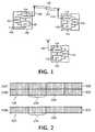
- a radio communication systemcomprises a primary station (BS) 100 and a plurality of secondary stations (MS) 110.
- the BS 100comprises a microcontroller ( ⁇ C) 102, transceiver means (Tx/Rx) 104 connected to antenna means 106, power control means (PC) 107 for altering the transmitted power level, and connection means 108 for connection to the PSTN or other suitable network.
- Each MS 110comprises a microcontroller ( ⁇ C) 112, transceiver means (Tx/Rx) 114 connected to antenna means 116, and power control means (PC) 118 for altering the transmitted power level.
- Communication from BS 100 to MS 110takes place on a downlink channel 122, while communication from MS 110 to BS 100 takes place on an uplink channel 124.
- One UMTS embodiment, the frequency division duplex modeuses the arrangement of channels of Figure 2 for transmitting packet data from a MS 110 to a BS 100.
- CONcontrol channels
- DATuplink data channel
- Transmissions on each of the channels 202,204,206take place in timeslots 208, which are grouped together in frames 210, each frame 210 comprising 15 timeslots.
- One or more transport channelsare multiplexed together by the system to form the single data channel 206.
- the control channels 202, 204include pilot, power control and transport format information.
- the pilot informationis primarily provided to allow the receiver to estimate the channel impulse response, in order to optimise detection of the received data (i.e. other information in the control channel and a data packet if present).
- Power control of the uplink channel 124is required so that the BS 100 receives signals from different MS 110 at a sufficient received Signal to Interference Ratio (SIR), while minimising the transmission power required by each MS 110.
- Power control of the downlink channel 122is required so that the MS 110 receives signals from the BS 100 with a low error rate while minimising transmission power, to reduce interference with other cells and radio systems.
- Power control of each of the channels 122,124uses an inner and an outer loop. The inner loop adjusts the received SIR to match a target SIR, while the outer loop adjusts the target SIR to the minimum level that will maintain the required quality of service (e.g. bit error rate).
- Transport format informationprovides details of the rate and transmission format of data on the accompanying data channel, to enable the transceivers 104,114 to be appropriately configured.
- this informationis provided by transmission of a Transport Format Combination Indicator (TFCl) word on the control channel 202 associated with the data channel 206.
- TFClTransport Format Combination Indicator
- the TFCI wordis supplied to the physical layer as a 10-bit information word, which is then coded into a 32-bit word using a 32,10 block code. Two bits of the word are transmitted in each timeslot 208, enabling 30 bits of the coded TFCI word to be transmitted in each frame while the remaining 2 bits are not transmitted.
- the MS 110does not have much data to transmit, there may be periods between transmission of data packets. Normally, the control channels 202,206 would be transmitted continuously between data packets in order to facilitate rapid transmission of packets as they arrive. However, this wastes power and generates interference without any useful data being transmitted, thereby reducing system capacity and the battery life of the MS 110.
- a gated modewas proposed (see for example WO 00/42804) in which the number of timeslots 208 per frame 210 for which the uplink control channel 202 is transmitted is reduced by a factor of 3 or 5.
- the actual position of the transmitted slots 208 in each frame 210is calculated according to a pseudo-random function in order to mitigate the electromagnetic interference which may be generated by the intermittent transmission.
- the downlink control channel 204may continue unaltered or may also be transmitted in a fraction of the available timeslots 208 during gated mode.
- Outer-loop power controlis typically based on the error rate of Cyclic Redundancy Checks (CRCs) appended to transport blocks on the data channel 206.
- CRCsCyclic Redundancy Checks
- one option for maintaining outer-loop power control during gatingis to use the Bit Error Rate (BER) of the control channel 202 instead of the data CRCs.
- BERBit Error Rate
- a solution to this problemis to transmit CRCs alone on the data channel 206 in the same slots 208 as the control channel 202 is transmitted, by appending CRCs to transport blocks of zero length.
- the optionscould be any permutation of no transport blocks or zero length transport blocks on any or all of the transport channels mapped to the data channel 206.
- the permissible TFCswould probably be limited to a subset of these options, but the minimum is likely to be one TFC for no transport blocks at all and one other TFC which includes some zero-length transport blocks to which CRCs would be appended.
- the codingis non-optimal, in the sense that the distance between the codewords (i.e. the number of bits that are different) for the first and second TFCs is only 3, compared to a possible maximum of 6, leading to an increased decoding error rate.
- the proposed UMTS coding schemeis designed so that if all 32 TFCI bits are transmitted, the TFCI codewords for the first 32 TFCs would be orthogonal. This gives a uniform minimum distance between the codewords, rather than a greater minimum distance between the codewords for the first few TFCs and a smaller minimum distance between subsequent TFCs. Orthogonality between codewords is not necessary in practice as the phase of the received signal carrier can be recovered separately from the pilot bits.
- the method for coding and mapping the 10-bit TFCI word from higher layers to the available bits in the radio frameis different in gated mode from the usual method of coding and mapping used in non-gated frames.
- the method of coding and mappingcan be designed to result in unique codewords for a larger range of TFCs than are obtained by simply truncating the usual codewords. Thus a larger number of TFCs are permitted than if the usual codewords are simply truncated.
- the method of coding and mappingcan be designed such that the codewords are arranged so as to have a larger Hamming distance between them when the number of permitted TFCs is small, in order to minimise the decoding error rate in Basic Gating Periods.
- the method of coding and mappingcan result in an inter-codeword distance equal to the number of transmitted bits (i.e. the maximum possible) when only two TFCs are permitted during gated mode. The TFCs for gated mode are then assigned low TFC numbers to correspond to large inter-codeword distances.
- the 10-bit TFCI word from higher layersis coded using the usual 32,10 code, but then is heavily punctured in a pre-defined manner.
- the puncturingis designed so that the coded TFCl words for the different TFCs which are permitted during gated mode have a high distance from each other.
- the distance between the transmitted codewords representing each TFCshould be equal to the number of transmitted TFCl bits in the frame 210. Since phase information can be obtained from transmitted pilot bits, maximising the separation of the codewords will give more reliable decoding performance for the small number of transmitted TFCl bits than making the transmitted codewords for the first two TFCs orthogonal.
- a linear combination of ten basis sequencesis used for the 32,10 block code.
- the output codeword bits b i , 0 ⁇ i ⁇ 31,are related to the information bits of the input TFCl word a n , 0 ⁇ n ⁇ 9, by where M i , n is the n th basis sequence.
- the basis sequences M i , n used in this embodimentare shown, by way of example, as a table in Figure 3.
- Different bits of the 32-bit codewordcan be punctured (meaning deleted) depending on the number of available physical layer bits for TFCI transmission.
- the maximum possible distances between transmitted codewordscan be achieved by many different puncturing patterns.
- the non-punctured bits for smaller numbers (e.g. 6) of transmitted bitsform a subset of the non-punctured bits for larger numbers (e.g. 10) of transmitted bits.
- There are many puncturing patternswhich meet this criterion in addition to maximising the distances between transmitted codewords for both gating rate 1/5 and gating rate 1/3.
- One such puncturing patternis obtained by transmitting only the bits of the coded bits b i shown in the following table: Gating Rate Transmitted Bits 1/3 0 4 6 8 10 17 19 21 27 29 1/5 0 4 6 8 10 17
- Figure 4is a graph showing the minimum distance M between codewords as a function of the number N of TFCs which are permitted during gated mode using the above patterns. Distances for a gating rate of 1/3 are shown as a solid line and for a gating rate of 1/5 as a dashed line. It can be seen that the minimum distances are especially optimised for the small numbers of TFCs which are likely to occur during gated mode, although there is also considerable flexibility for the support of larger numbers of TFCs if desired in the future.
- Figure 5is a graph showing the minimum distance M between codewords as a function of the number N of TFCs in the TFCS using the above patterns. Distances for a gating rate of 1/3 are shown as a solid line and for a gating rate of 1/5 as a dashed line.
- a different coding schemecould be used for the TFCl word in gated mode, for example a 6,10 or 10,10 code designed to have similar distance properties to those described above.
- the number of TFCs in the TFCScould be restricted to a value less than or equal to the highest TFC number which can be coded uniquely by whatever coding scheme is used by the physical layer.
- the number of TFCscould be restricted to 32 or fewer.
- a special case of the above embodimentsresults from restricting the number of TFCs to two and choosing a puncturing scheme that results in all the transmitted bits of the first TFCl word being different from all those of the second TFCl word, for example all transmitted bits of the first TFCl word being 0 and all transmitted bits of the second TFCI word being 1 (or vice-versa).
- a further solutionwhich could be used instead of or in addition to the above embodiments, is to increase the number of available physical layer bits for transmitting the TFCl word.
- a different slot formatcould be used on the control channel.
- One possibilitywould be to use the UMTS compressed mode slot formats, which have 3 or 4 TFCI bits per slot at the expense of fewer pilot bits. This would mean that the transmit power of the control channel (in those slots which were transmitted) would have to be increased in order to keep the total pilot energy per slot the same. However, this would partially defeat the purpose of gating in reducing power consumption.
- each TFCl wordcould be transmitted over a period of more than one radio frame. For example, using a pair of consecutive radio frames for the transmission of each TFCI word would enable 12 coded TFCI bits to be transmitted for gating rate 1/5, or 20 for gating rate 1/3.
- this alternativehas the disadvantages of preventing the TFC from being changed every frame and increasing the latency before data can be decoded.
- the present inventionhas been described in relation to gated mode applied to low duty cycle data transmissions on an uplink channel 124. However, it is equally applicable to transmissions on a downlink channel 122, in which case the roles of the BS 100 and MS 110 would be reversed in the description above, with the BS 100 adopting the role of a secondary station and the MS 110 the role of a primary station.
- base stationor "primary station” is to be understood to include the parts of the network fixed infrastructure which interface with mobile stations.
- CDMACode Division Multiple Access
Landscapes
- Engineering & Computer Science (AREA)
- Computer Networks & Wireless Communication (AREA)
- Signal Processing (AREA)
- Computer Security & Cryptography (AREA)
- Mobile Radio Communication Systems (AREA)
- Radio Relay Systems (AREA)
- Transceivers (AREA)
- Transmitters (AREA)
Abstract
Description

There are many puncturing patterns which meet this criterion in addition tomaximising the distances between transmitted codewords for both
| Gating Rate | Transmitted | |||||||||
| 1/3 | 0 | 4 | 6 | 8 | 10 | 17 | 19 | 21 | 27 | 29 |
| 1/5 | 0 | 4 | 6 | 8 | 10 | 17 |
| Gating Rate | Transmitted | |||||||||
| 1/3 | 0 | 2 | 4 | 9 | 14 | 16 | 17 | 27 | 28 | 30 |
| 1/5 | 0 | 2 | 4 | 9 | 14 | 16 |
Claims (12)
- A radio communication system comprising a communicationchannel for the transmission of data from a secondary station (MS) to a primarystation (BS), the secondary station being operable in a first and a secondmode and comprising means for repeatedly transmitting a coded word (TFCI)providing information on transport formats applicable to the channel, andmeans for transmitting a reduced quantity of information when operating in thesecond mode compared to that transmitted when operating in the first mode,and the primary station comprising means for receiving and decoding the codeword (TFCI),characterised in that the secondary station comprises means for using a differentcoding scheme to generate the coded word (TFCI) in each of the modes and theprimary station comprises means for selecting one of two different decodingschemes depending on the current mode of operation of the secondary station (MS)and for decoding the coded word using the selected decoding scheme.
- A system as claimed in claim 1,characterised in that thesecondary station comprises means for using a coding scheme during thesecond mode which generates a code word that is a punctured version of thecode word that would be generated by the coding scheme used during the firstmode.
- A primary station (BS) for use in a radio communication systemcomprising a communication channel for the transmission of data from asecondary station to the primary station,characterised in that means are provided forrepeatedly receiving from the secondary station a coded word providinginformation on transport formats applicable to the channel, for determiningwhether the secondary station is operating in a first or a secondmode, for selecting one of two different decoding schemes dependingon the current mode of operation of the secondary station and for decoding thecoded word (TFCI) using the selected decoding scheme.
- A secondary station (MS) for use in a radio communication systemcomprising a communication channel for the transmission of data from thesecondary station to a primary station, the secondary station being operable ina first and a second mode and comprising means forrepeatedly transmitting a coded word (TFCI) providing information on transportformats applicable to the channel, and means for transmitting a reducedquantity of information when operating in the second mode compared to thattransmitted when operating in the first mode,characterised in that the secondary stationcomprises means for using a different coding scheme to generate the codedword in each of the modes.
- A secondary station as claimed in claim 4,characterised in thatmeans are provided for using a coding scheme during the second mode whichgenerates a code word that is a punctured version of the code word that wouldbe generated by the coding scheme used during the first mode.
- A secondary station as claimed in claim 4 or 5,characterised inthat means are provided for restricting the number of available transportformats during operation of the second mode to no more than the number ofunique code words able to be generated by the coding scheme employed.
- A method of operating a radio communication system comprisinga communication channel for the transmission of data from a secondary station (MS)to a primary station (BS), the secondary station being operable in a firstand a second mode, the method comprising the secondary stationrepeatedly transmitting a coded word (TFCI) providing information on transportformats applicable to the channel and transmitting a reduced quantity ofinformation when operating in the second mode compared to that transmittedwhen operating in the first mode, and the primary station receiving anddecoding the code word, wherein the secondary station uses a different codingscheme to generate the coded word in each of the modes and the primarystation selects one of two different decoding schemes depending on the current mode of operation of the secondary station and decodes the codedword using the selected decoding scheme.
- A method as claimed in claim 7,characterised by the secondarystation using a coding scheme during the second mode which generates acode word that is a punctured version of the code word that would begenerated by the coding scheme used during the first mode.
- A method as claimed in claim 8,characterised by the secondmode being operable at a plurality of different information rates and by thecoding scheme for a lower information rate generating a code word that is atruncated version of the code word generated for a higher information rate.
- A method as claimed in claim 8 or 9,characterised by thepuncturing pattern being arranged to maximise the distance between codewords in a set of code words, which set is smaller than the set of code wordsavailable during the first mode.
- A method as claimed in claim 10,characterised by there beingonly two possible transport format combinations during operation of thesecond mode, each represented by a different code word, and by thepuncturing scheme ensuring that all the bits of the code words are different.
- A method as claimed in claim 8 or 9,characterised by thepuncturing pattern being arranged to minimise the number of code wordswhich have the smallest distance between them.
Applications Claiming Priority (3)
| Application Number | Priority Date | Filing Date | Title |
|---|---|---|---|
| GB0108381 | 2001-04-04 | ||
| GBGB0108381.5AGB0108381D0 (en) | 2001-04-04 | 2001-04-04 | Radio communication system |
| PCT/IB2002/000941WO2002087274A1 (en) | 2001-04-04 | 2002-03-21 | Radio communication system for gated transmission of a control channel |
Publications (2)
| Publication Number | Publication Date |
|---|---|
| EP1378143A1 EP1378143A1 (en) | 2004-01-07 |
| EP1378143B1true EP1378143B1 (en) | 2005-01-26 |
Family
ID=9912193
Family Applications (1)
| Application Number | Title | Priority Date | Filing Date |
|---|---|---|---|
| EP02714382AExpired - LifetimeEP1378143B1 (en) | 2001-04-04 | 2002-03-21 | Radio communication system for gated transmission of a control channel |
Country Status (9)
| Country | Link |
|---|---|
| US (1) | US7554953B2 (en) |
| EP (1) | EP1378143B1 (en) |
| JP (1) | JP3939659B2 (en) |
| KR (1) | KR20030007856A (en) |
| CN (1) | CN1224290C (en) |
| AT (1) | ATE288176T1 (en) |
| DE (1) | DE60202759T2 (en) |
| GB (1) | GB0108381D0 (en) |
| WO (1) | WO2002087274A1 (en) |
Families Citing this family (17)
| Publication number | Priority date | Publication date | Assignee | Title |
|---|---|---|---|---|
| US7302009B2 (en)* | 2003-12-17 | 2007-11-27 | Qualcomm Incorporated | Broadcast transmission with spatial spreading in a multi-antenna communication system |
| US8204149B2 (en) | 2003-12-17 | 2012-06-19 | Qualcomm Incorporated | Spatial spreading in a multi-antenna communication system |
| US7336746B2 (en)* | 2004-12-09 | 2008-02-26 | Qualcomm Incorporated | Data transmission with spatial spreading in a MIMO communication system |
| US8169889B2 (en) | 2004-02-18 | 2012-05-01 | Qualcomm Incorporated | Transmit diversity and spatial spreading for an OFDM-based multi-antenna communication system |
| US8285226B2 (en) | 2004-05-07 | 2012-10-09 | Qualcomm Incorporated | Steering diversity for an OFDM-based multi-antenna communication system |
| US8923785B2 (en) | 2004-05-07 | 2014-12-30 | Qualcomm Incorporated | Continuous beamforming for a MIMO-OFDM system |
| US7110463B2 (en)* | 2004-06-30 | 2006-09-19 | Qualcomm, Incorporated | Efficient computation of spatial filter matrices for steering transmit diversity in a MIMO communication system |
| US7978649B2 (en) | 2004-07-15 | 2011-07-12 | Qualcomm, Incorporated | Unified MIMO transmission and reception |
| US7978778B2 (en)* | 2004-09-03 | 2011-07-12 | Qualcomm, Incorporated | Receiver structures for spatial spreading with space-time or space-frequency transmit diversity |
| US7894548B2 (en)* | 2004-09-03 | 2011-02-22 | Qualcomm Incorporated | Spatial spreading with space-time and space-frequency transmit diversity schemes for a wireless communication system |
| CN100461935C (en)* | 2004-11-12 | 2009-02-11 | 华为技术有限公司 | Uplink Enhanced Control Channel Signaling Coding Method |
| US7831269B2 (en)* | 2005-07-21 | 2010-11-09 | Research In Motion Limited | System and associated method for facilitating push-to-talk communications |
| BRPI0614783B1 (en)* | 2005-08-05 | 2019-06-25 | Nokia Technologies Oy | METHOD, USER EQUIPMENT, NETWORK ELEMENT AND COMMUNICATION SYSTEM |
| TWI415417B (en)* | 2006-02-03 | 2013-11-11 | Lg Electronics Inc | Method for performance enhancement in a cell edge region |
| US8543070B2 (en) | 2006-04-24 | 2013-09-24 | Qualcomm Incorporated | Reduced complexity beam-steered MIMO OFDM system |
| US8290089B2 (en) | 2006-05-22 | 2012-10-16 | Qualcomm Incorporated | Derivation and feedback of transmit steering matrix |
| US9854519B2 (en)* | 2014-01-28 | 2017-12-26 | Mediatek Inc. | Handheld device, base station and transmission control method thereof |
Family Cites Families (12)
| Publication number | Priority date | Publication date | Assignee | Title |
|---|---|---|---|---|
| JPH06105884B2 (en)* | 1986-05-06 | 1994-12-21 | 日本電気株式会社 | Wireless telephone system |
| US5056109A (en)* | 1989-11-07 | 1991-10-08 | Qualcomm, Inc. | Method and apparatus for controlling transmission power in a cdma cellular mobile telephone system |
| US5659569A (en)* | 1990-06-25 | 1997-08-19 | Qualcomm Incorporated | Data burst randomizer |
| WO1996022003A1 (en)* | 1995-01-10 | 1996-07-18 | Ntt Mobile Communications Network Inc. | Mobile communication system |
| US5883899A (en)* | 1995-05-01 | 1999-03-16 | Telefonaktiebolaget Lm Ericsson | Code-rate increased compressed mode DS-CDMA systems and methods |
| US6101626A (en)* | 1998-02-04 | 2000-08-08 | Lsi Logic Corporation | Method for choosing coding schemes, mappings, and puncturing rates for modulations/encoding systems |
| TW459461B (en) | 1999-01-16 | 2001-10-11 | Koninkl Philips Electronics Nv | Radio communication system |
| CN1186893C (en)* | 1999-04-12 | 2005-01-26 | 三星电子株式会社 | Apparatus and method for gated transmission in CDMA communication system |
| EP1080543B1 (en)* | 1999-04-12 | 2012-01-04 | Samsung Electronics Co., Ltd. | Method for controlling gated transmission of dedicated channel in w-cdma communication system |
| US6882636B1 (en)* | 1999-07-06 | 2005-04-19 | Samsung Electronics Co., Ltd. | Apparatus and method for encoding/decoding transport format combination indicator in CDMA mobile communication system |
| US6496706B1 (en)* | 1999-07-23 | 2002-12-17 | Qualcomm Incorporated | Method and system for transmit gating in a wireless communication system |
| KR100407942B1 (en)* | 1999-11-19 | 2003-12-01 | 엘지전자 주식회사 | method for improving transmission performance of Transport Format Combination Indicato in a mobile communication system |
- 2001
- 2001-04-04GBGBGB0108381.5Apatent/GB0108381D0/ennot_activeCeased
- 2002
- 2002-03-21CNCNB028010574Apatent/CN1224290C/ennot_activeExpired - Fee Related
- 2002-03-21WOPCT/IB2002/000941patent/WO2002087274A1/enactiveIP Right Grant
- 2002-03-21ATAT02714382Tpatent/ATE288176T1/ennot_activeIP Right Cessation
- 2002-03-21DEDE60202759Tpatent/DE60202759T2/ennot_activeExpired - Lifetime
- 2002-03-21EPEP02714382Apatent/EP1378143B1/ennot_activeExpired - Lifetime
- 2002-03-21KRKR1020027016499Apatent/KR20030007856A/ennot_activeCeased
- 2002-03-21JPJP2002584649Apatent/JP3939659B2/ennot_activeExpired - Fee Related
- 2002-04-01USUS10/113,051patent/US7554953B2/ennot_activeExpired - Fee Related
Also Published As
| Publication number | Publication date |
|---|---|
| WO2002087274A1 (en) | 2002-10-31 |
| JP3939659B2 (en) | 2007-07-04 |
| KR20030007856A (en) | 2003-01-23 |
| JP2004529564A (en) | 2004-09-24 |
| US20020196742A1 (en) | 2002-12-26 |
| CN1460391A (en) | 2003-12-03 |
| CN1224290C (en) | 2005-10-19 |
| EP1378143A1 (en) | 2004-01-07 |
| US7554953B2 (en) | 2009-06-30 |
| ATE288176T1 (en) | 2005-02-15 |
| GB0108381D0 (en) | 2001-05-23 |
| DE60202759D1 (en) | 2005-03-03 |
| DE60202759T2 (en) | 2006-01-12 |
Similar Documents
| Publication | Publication Date | Title |
|---|---|---|
| EP1378143B1 (en) | Radio communication system for gated transmission of a control channel | |
| US7561594B2 (en) | User equipment having improved power savings during full and partial DTX modes of operation | |
| US7386277B2 (en) | Communication system and method for increasing communication efficiency | |
| US8457092B2 (en) | Quick paging channel with reduced probability of missed page | |
| EP1114536B1 (en) | Method and system for alternating transmission of codec mode information | |
| JP4544801B2 (en) | Transmission power control method in radio system and radio system corresponding thereto | |
| US9736793B2 (en) | Format adaptation of a control channel for discontinuous data transmission | |
| CN101300769B (en) | Dedicated control channel detection for enhanced dedicated channel | |
| JP2010093843A (en) | Data transmission method | |
| EP1317092B1 (en) | Apparatus and method for transmitting and receiving data on packet data control channel | |
| JP2001244912A (en) | CDMA cellular radio transmission system | |
| US7171229B2 (en) | Method for operating a radio communication system | |
| EP1222761B1 (en) | Methods and systems for robust frame type protection in systems employing variable bit rates | |
| JP3543759B2 (en) | Transmission power control method, transmitting / receiving apparatus, base station and mobile station | |
| US20030148781A1 (en) | Method for regulating transmission power in a radio system | |
| US20060036434A1 (en) | Resource reservation in transmission networks | |
| US20100103882A1 (en) | Early termination of low data rate traffic in a wireless network | |
| US6580753B1 (en) | Method of transmitting information via a telecommunication system and corresponding telecommunication system | |
| JP4582610B2 (en) | Method for controlling transmission output in radio system and corresponding radio system | |
| US7664140B2 (en) | Early termination of low data rate traffic in a wireless network |
Legal Events
| Date | Code | Title | Description |
|---|---|---|---|
| PUAI | Public reference made under article 153(3) epc to a published international application that has entered the european phase | Free format text:ORIGINAL CODE: 0009012 | |
| 17P | Request for examination filed | Effective date:20031104 | |
| AK | Designated contracting states | Kind code of ref document:A1 Designated state(s):AT BE CH CY DE DK ES FI FR GB GR IE IT LI LU MC NL PT SE TR | |
| GRAP | Despatch of communication of intention to grant a patent | Free format text:ORIGINAL CODE: EPIDOSNIGR1 | |
| GRAS | Grant fee paid | Free format text:ORIGINAL CODE: EPIDOSNIGR3 | |
| GRAA | (expected) grant | Free format text:ORIGINAL CODE: 0009210 | |
| AK | Designated contracting states | Kind code of ref document:B1 Designated state(s):AT BE CH CY DE DK ES FI FR GB GR IE IT LI LU MC NL PT SE TR | |
| PG25 | Lapsed in a contracting state [announced via postgrant information from national office to epo] | Ref country code:IT Free format text:LAPSE BECAUSE OF FAILURE TO SUBMIT A TRANSLATION OF THE DESCRIPTION OR TO PAY THE FEE WITHIN THE PRESCRIBED TIME-LIMIT;WARNING: LAPSES OF ITALIAN PATENTS WITH EFFECTIVE DATE BEFORE 2007 MAY HAVE OCCURRED AT ANY TIME BEFORE 2007. THE CORRECT EFFECTIVE DATE MAY BE DIFFERENT FROM THE ONE RECORDED. Effective date:20050126 Ref country code:AT Free format text:LAPSE BECAUSE OF FAILURE TO SUBMIT A TRANSLATION OF THE DESCRIPTION OR TO PAY THE FEE WITHIN THE PRESCRIBED TIME-LIMIT Effective date:20050126 Ref country code:NL Free format text:LAPSE BECAUSE OF FAILURE TO SUBMIT A TRANSLATION OF THE DESCRIPTION OR TO PAY THE FEE WITHIN THE PRESCRIBED TIME-LIMIT Effective date:20050126 Ref country code:LI Free format text:LAPSE BECAUSE OF FAILURE TO SUBMIT A TRANSLATION OF THE DESCRIPTION OR TO PAY THE FEE WITHIN THE PRESCRIBED TIME-LIMIT Effective date:20050126 Ref country code:FI Free format text:LAPSE BECAUSE OF FAILURE TO SUBMIT A TRANSLATION OF THE DESCRIPTION OR TO PAY THE FEE WITHIN THE PRESCRIBED TIME-LIMIT Effective date:20050126 Ref country code:CH Free format text:LAPSE BECAUSE OF FAILURE TO SUBMIT A TRANSLATION OF THE DESCRIPTION OR TO PAY THE FEE WITHIN THE PRESCRIBED TIME-LIMIT Effective date:20050126 Ref country code:BE Free format text:LAPSE BECAUSE OF FAILURE TO SUBMIT A TRANSLATION OF THE DESCRIPTION OR TO PAY THE FEE WITHIN THE PRESCRIBED TIME-LIMIT Effective date:20050126 Ref country code:TR Free format text:LAPSE BECAUSE OF FAILURE TO SUBMIT A TRANSLATION OF THE DESCRIPTION OR TO PAY THE FEE WITHIN THE PRESCRIBED TIME-LIMIT Effective date:20050126 | |
| REG | Reference to a national code | Ref country code:GB Ref legal event code:FG4D | |
| REG | Reference to a national code | Ref country code:CH Ref legal event code:EP | |
| REG | Reference to a national code | Ref country code:IE Ref legal event code:FG4D | |
| REF | Corresponds to: | Ref document number:60202759 Country of ref document:DE Date of ref document:20050303 Kind code of ref document:P | |
| PG25 | Lapsed in a contracting state [announced via postgrant information from national office to epo] | Ref country code:LU Free format text:LAPSE BECAUSE OF NON-PAYMENT OF DUE FEES Effective date:20050321 Ref country code:IE Free format text:LAPSE BECAUSE OF NON-PAYMENT OF DUE FEES Effective date:20050321 Ref country code:CY Free format text:LAPSE BECAUSE OF FAILURE TO SUBMIT A TRANSLATION OF THE DESCRIPTION OR TO PAY THE FEE WITHIN THE PRESCRIBED TIME-LIMIT Effective date:20050321 | |
| PG25 | Lapsed in a contracting state [announced via postgrant information from national office to epo] | Ref country code:MC Free format text:LAPSE BECAUSE OF NON-PAYMENT OF DUE FEES Effective date:20050331 | |
| PG25 | Lapsed in a contracting state [announced via postgrant information from national office to epo] | Ref country code:DK Free format text:LAPSE BECAUSE OF FAILURE TO SUBMIT A TRANSLATION OF THE DESCRIPTION OR TO PAY THE FEE WITHIN THE PRESCRIBED TIME-LIMIT Effective date:20050426 Ref country code:GR Free format text:LAPSE BECAUSE OF FAILURE TO SUBMIT A TRANSLATION OF THE DESCRIPTION OR TO PAY THE FEE WITHIN THE PRESCRIBED TIME-LIMIT Effective date:20050426 Ref country code:SE Free format text:LAPSE BECAUSE OF FAILURE TO SUBMIT A TRANSLATION OF THE DESCRIPTION OR TO PAY THE FEE WITHIN THE PRESCRIBED TIME-LIMIT Effective date:20050426 | |
| PG25 | Lapsed in a contracting state [announced via postgrant information from national office to epo] | Ref country code:ES Free format text:LAPSE BECAUSE OF FAILURE TO SUBMIT A TRANSLATION OF THE DESCRIPTION OR TO PAY THE FEE WITHIN THE PRESCRIBED TIME-LIMIT Effective date:20050507 | |
| REG | Reference to a national code | Ref country code:GB Ref legal event code:746 Effective date:20050419 | |
| NLV1 | Nl: lapsed or annulled due to failure to fulfill the requirements of art. 29p and 29m of the patents act | ||
| REG | Reference to a national code | Ref country code:CH Ref legal event code:PL | |
| PLBE | No opposition filed within time limit | Free format text:ORIGINAL CODE: 0009261 | |
| STAA | Information on the status of an ep patent application or granted ep patent | Free format text:STATUS: NO OPPOSITION FILED WITHIN TIME LIMIT | |
| REG | Reference to a national code | Ref country code:IE Ref legal event code:MM4A | |
| 26N | No opposition filed | Effective date:20051027 | |
| ET | Fr: translation filed | ||
| PG25 | Lapsed in a contracting state [announced via postgrant information from national office to epo] | Ref country code:PT Free format text:LAPSE BECAUSE OF NON-PAYMENT OF DUE FEES Effective date:20050626 | |
| PGFP | Annual fee paid to national office [announced via postgrant information from national office to epo] | Ref country code:DE Payment date:20100531 Year of fee payment:9 | |
| PGFP | Annual fee paid to national office [announced via postgrant information from national office to epo] | Ref country code:FR Payment date:20110414 Year of fee payment:10 Ref country code:GB Payment date:20110331 Year of fee payment:10 | |
| PG25 | Lapsed in a contracting state [announced via postgrant information from national office to epo] | Ref country code:DE Free format text:LAPSE BECAUSE OF NON-PAYMENT OF DUE FEES Effective date:20111001 | |
| REG | Reference to a national code | Ref country code:DE Ref legal event code:R119 Ref document number:60202759 Country of ref document:DE Effective date:20111001 | |
| GBPC | Gb: european patent ceased through non-payment of renewal fee | Effective date:20120321 | |
| REG | Reference to a national code | Ref country code:FR Ref legal event code:ST Effective date:20121130 | |
| PG25 | Lapsed in a contracting state [announced via postgrant information from national office to epo] | Ref country code:FR Free format text:LAPSE BECAUSE OF NON-PAYMENT OF DUE FEES Effective date:20120402 Ref country code:GB Free format text:LAPSE BECAUSE OF NON-PAYMENT OF DUE FEES Effective date:20120321 |