EP1374782A2 - Prosthesis cutting guide and cutting tool - Google Patents
Prosthesis cutting guide and cutting toolDownload PDFInfo
- Publication number
- EP1374782A2 EP1374782A2EP03253924AEP03253924AEP1374782A2EP 1374782 A2EP1374782 A2EP 1374782A2EP 03253924 AEP03253924 AEP 03253924AEP 03253924 AEP03253924 AEP 03253924AEP 1374782 A2EP1374782 A2EP 1374782A2
- Authority
- EP
- European Patent Office
- Prior art keywords
- guide
- tool
- bone
- kit
- cavity
- Prior art date
- Legal status (The legal status is an assumption and is not a legal conclusion. Google has not performed a legal analysis and makes no representation as to the accuracy of the status listed.)
- Withdrawn
Links
- 0*CC1CCCC1Chemical compound*CC1CCCC10.000description2
- XDEIUJDNPOTFSD-UHFFFAOYSA-NC(C1)C2C1[IH]CC2Chemical compoundC(C1)C2C1[IH]CC2XDEIUJDNPOTFSD-UHFFFAOYSA-N0.000description1
- XDTMQSROBMDMFD-UHFFFAOYSA-NC1CCCCC1Chemical compoundC1CCCCC1XDTMQSROBMDMFD-UHFFFAOYSA-N0.000description1
- DEDZSLCZHWTGOR-UHFFFAOYSA-NCCCC1CCCCC1Chemical compoundCCCC1CCCCC1DEDZSLCZHWTGOR-UHFFFAOYSA-N0.000description1
Images


Classifications
- A—HUMAN NECESSITIES
- A61—MEDICAL OR VETERINARY SCIENCE; HYGIENE
- A61B—DIAGNOSIS; SURGERY; IDENTIFICATION
- A61B17/00—Surgical instruments, devices or methods
- A61B17/16—Instruments for performing osteoclasis; Drills or chisels for bones; Trepans
- A61B17/1662—Instruments for performing osteoclasis; Drills or chisels for bones; Trepans for particular parts of the body
- A61B17/1675—Instruments for performing osteoclasis; Drills or chisels for bones; Trepans for particular parts of the body for the knee
- A—HUMAN NECESSITIES
- A61—MEDICAL OR VETERINARY SCIENCE; HYGIENE
- A61B—DIAGNOSIS; SURGERY; IDENTIFICATION
- A61B17/00—Surgical instruments, devices or methods
- A61B17/16—Instruments for performing osteoclasis; Drills or chisels for bones; Trepans
- A61B17/1613—Component parts
- A61B17/1615—Drill bits, i.e. rotating tools extending from a handpiece to contact the worked material
- A—HUMAN NECESSITIES
- A61—MEDICAL OR VETERINARY SCIENCE; HYGIENE
- A61B—DIAGNOSIS; SURGERY; IDENTIFICATION
- A61B17/00—Surgical instruments, devices or methods
- A61B17/16—Instruments for performing osteoclasis; Drills or chisels for bones; Trepans
- A61B17/17—Guides or aligning means for drills, mills, pins or wires
- A61B17/1739—Guides or aligning means for drills, mills, pins or wires specially adapted for particular parts of the body
- A61B17/1764—Guides or aligning means for drills, mills, pins or wires specially adapted for particular parts of the body for the knee
- A—HUMAN NECESSITIES
- A61—MEDICAL OR VETERINARY SCIENCE; HYGIENE
- A61B—DIAGNOSIS; SURGERY; IDENTIFICATION
- A61B17/00—Surgical instruments, devices or methods
- A61B17/16—Instruments for performing osteoclasis; Drills or chisels for bones; Trepans
- A61B17/17—Guides or aligning means for drills, mills, pins or wires
- A61B17/1739—Guides or aligning means for drills, mills, pins or wires specially adapted for particular parts of the body
- A61B17/1742—Guides or aligning means for drills, mills, pins or wires specially adapted for particular parts of the body for the hip
- A—HUMAN NECESSITIES
- A61—MEDICAL OR VETERINARY SCIENCE; HYGIENE
- A61B—DIAGNOSIS; SURGERY; IDENTIFICATION
- A61B17/00—Surgical instruments, devices or methods
- A61B17/16—Instruments for performing osteoclasis; Drills or chisels for bones; Trepans
- A61B17/17—Guides or aligning means for drills, mills, pins or wires
- A61B17/1739—Guides or aligning means for drills, mills, pins or wires specially adapted for particular parts of the body
- A61B17/1778—Guides or aligning means for drills, mills, pins or wires specially adapted for particular parts of the body for the shoulder
- A—HUMAN NECESSITIES
- A61—MEDICAL OR VETERINARY SCIENCE; HYGIENE
- A61B—DIAGNOSIS; SURGERY; IDENTIFICATION
- A61B17/00—Surgical instruments, devices or methods
- A61B17/16—Instruments for performing osteoclasis; Drills or chisels for bones; Trepans
- A61B2017/1602—Mills
- A—HUMAN NECESSITIES
- A61—MEDICAL OR VETERINARY SCIENCE; HYGIENE
- A61B—DIAGNOSIS; SURGERY; IDENTIFICATION
- A61B90/00—Instruments, implements or accessories specially adapted for surgery or diagnosis and not covered by any of the groups A61B1/00 - A61B50/00, e.g. for luxation treatment or for protecting wound edges
- A61B90/03—Automatic limiting or abutting means, e.g. for safety
- A61B2090/033—Abutting means, stops, e.g. abutting on tissue or skin
Definitions
- the present inventionrelates generally to the field of orthopaedics, and more particularly, to an implant for use in arthroplasty.
- Joint replacement surgeryis quite common and it enables many individuals to function properly when it would not otherwise be possible to do so. Such patients of joint replacement surgery typically suffer from osteoarthritis or rheumatoid arthritis. Artificial joints usually comprise metallic, ceramic and/or plastic components that are fixed to existing bone.
- Total joint arthroplastyis a well known surgical procedure by which a diseased and/or damaged joint is replaced with a prosthetic joint.
- a typical total joint arthroplastythe adjacent ends of the bones and cartilage comprising the joint are resected and the artificial implants are secured thereto.
- patello femoral arthroplastyWhen only the patellar articular surface and the adjacent groove on the distal end of the femur, the trochlear, with which it articulates, are damaged, replacement of these surfaces is called a patello femoral arthroplasty.
- cartilage and bonewhen installing the components of the prosthetic joint, cartilage and bone must be resected or removed such that the implanted prosthesis has the same surface profile as the surface prior to its resection.
- Such arthroplastythus requires a pocket formed in the bone of a particular shape and depth to provide a location for the prosthesis such that the prosthesis outer-profile replicates that of the pre-resected joint.
- a trochlear implantfor cooperation with a patella prosthesis for a patello femoral arthroplasty.
- the current process for preparing to implant a trochlear prosthesisis to place a template over the femur where the damaged trochlear is located.
- the trochlear groove of the femuris then physically marked with a tool such as a scribe or marking pen which leaves a mark on the bone or cartilage as the scribe or pen is moved about the periphery of the template.
- the traced marks on the distal femurserve as a guide for preparing the pocket for the trochlear implant.
- Osteotomes and hammer plus high-speed rotating burrsare then used to prepare the pocket within the outlined perimeter. This process is very slow and tedious in order to achieve a precise and accurate fit in all dimensions.
- the present inventionis directed to a cutting guide, which is utilized with a rotating cutting tool to create pockets at a specific depth in the bone for a trochlear or similar implant.
- the cutting guideprovides an accurate cut both in the outline shape and in the depth of the cut. Additional cutting paths are made inside the outline shape utilizing the cutting tool so that only a minimal amount of material must be removed between the cutting path.
- a kit for removal of cartilage and bone from a patient to prepare a cavity for receiving a joint prosthesisincludes a guide for cooperation with the bone and a rotatable tool.
- the toolis constrainable by the guide for removal of the bone.
- the guideincludes a first portion thereof cooperable with the tool and a second portion thereof cooperable with the bone.
- a guidefor guiding a rotatable tool for removal of cartilage and bone from a patient to prepare a cavity for receiving a joint prosthesis.
- the guideincludes a first portion thereof cooperable with the tool and a second portion cooperable with the bone.
- a rotatable tooladapted for removal of cartilage and bone from a patient to prepare a cavity for receiving a joint prosthesis.
- the toolis constrainable by the guide for removal of the bone.
- a method for removal of cartilage and bone from a patient to prepare a cavity for receiving a joint prosthesisincludes the steps of providing a guide defining an opening therein, exposing a portion of the bone of the patient, placing the guide in cooperation with the bone, providing a tool adapted for cooperation with the opening, inserting the tool at least partially within the opening, causing the tool to move relatively to the guide, and advancing the tool within the opening to form the bone cavity.
- the technical advantage of the present inventionincludes an improved imprint or location of the pocket for the prosthesis.
- the guideincludes channels positioned about the outer periphery of the guide, which conform to the outer periphery of the pocket for placing the implant.
- the toolis moved about the pocket to provide for a pocket with an outer periphery that is well defined and accurate.
- the present inventionprovides for an improved and accurate location of the pocket for the prosthesis.
- the toolincludes a collar, which cooperates with the guide when the tool is placed in the channels of the guide.
- the collar on the toolseats against the rim around the channels and provides for an accurate and consistent depth of the pocket for the implant.
- the guideincludes a plurality of spaced apart channels. These channels occupy most of the cross-sectional area of the guide.
- the guidein cooperation with the tool, is used to form most of the pocket for the implant. Only a quick and simple use of a small osteotome to remove the small portions of material remaining after the utilization of the burr tool and guide, is required and that can be quickly accomplished. Therefore, with the rapid use of the guide and the burr tool and the minimal use of the osteotome, the pocket may be prepared very quickly and accurately.
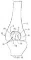
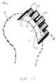
- FIG. 1show a kit 10 for removal of bone 12, for example, a portion of a long bone, from a patient to prepare a bone cavity 14 for receiving a joint prosthesis 16 (see FIGS. 11-14), is shown.
- the kit 10includes a guide 20 for cooperation with the long bone 12.
- the kit 10also includes a Rotatable tool 22, which is constrained by the guide 20 for removal of the bone 12.
- the guide 20includes a first portion 24 of the guide 20, which cooperates with the tool 22.
- the guide 20further includes a second portion 26 of the guide 20, which cooperates with the long bone 12.
- the first portion 24 of the guide 20defines a channel 30 through the guide 20.
- the tool 22is guidable within the channel 30.
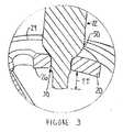
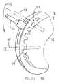
- FIGS. 4, 5 and 6the guide 20 is shown in greater detail.
- the channels 30are shown on first portion 24 of the guide 20.
- the channels 30may include arcuate periphery channels 32 as well as Lower periphery channels 34.
- the periphery channels 32 and 34are, as shown in FIG. 6, positioned around periphery 36 of the bone cavity 12 as shown in phantom.
- the periphery channels 32 and 34are utilized to guide the tool 22 in a path, which corresponds, to periphery 36 of the bone cavity 12.
- the periphery channels 32must be spaced from each other.
- the spacingprovides for support lands 40 which are positioned between adjacent periphery channels 32 and 34.
- the lands 40provide for rigidity to the guide 20. It should be appreciated that upon utilization of the guide 20 and the tool 22, the portions of the bone 12 corresponding to the lands 40 on the guide 20 represent portions of the bone, which must be removed by another tool (for example osteotome not shown).
- internal channels 42may be positioned within the guide 20 to provide for removal of additional bone from the bone cavity 12 in an area within the periphery 36 of the bone cavity 12. To provide for sufficient rigidity to the guide 20, the internal channels 42 are separated from each other.
- the minimal acceptable distance D between adjacent channelsmay vary.
- the distance Dshould be the minimum distance required for sufficient strength of the guide 20.
- the distancedmay be as little as 1.0 mm (0.04 inch).
- the guide 20is shown in position against bone 12.
- the tool, guide and kit of the present inventionmay be utilized to form a bone cavity in a bone in positions, in addition to the patella femoral joint described in FIGS. 1-6.
- the guide and tool of the present inventionmay be utilized to form any bone cavity, which may be necessary to provide a mounting location for a prosthetic implant.
- the guide, tool and kit of the present inventionis particularly well suited for utilization in a implant which has a generally uniform thickness and is designed to have an outer contour similar to that of the bone for which it replaces.
- the tool guide and kit of the present inventionmay be well suited for unicondylar knee replacement in which a unicondylar knee having a generally uniform thickness is used to replace the resected bone.
- Other common joints particularly partial implants of the shoulder, knee or hipmay be well suited to the use of the guide tool and kit of the present invention.
- the guide 20is preferably placed over outer periphery 44 of the bone 12.
- the bone 12is a femur and the guide 20 has an inner periphery 46 on second portion 26 of the guide 20, which preferably conforms, closely to outer periphery 44 of the bone 12.
- the tool 20includes a body 50 including a cutting edge 52 on an outer periphery thereof.
- the body 50has a body diameter DD which is slidingly fitted within the channels 30 of the guide 20.
- the width W of the channels 30is thus slightly larger than the diameter DD of the body 50.
- the tool 22preferably includes a stop 54, which limits the motion of the tool 22 in the direction of arrow 56 such that the stop 54 rests against the guide 20.
- the cutting edge 52 of the tool 22extends inwardly from inner periphery 46 of the guide 20 a distance TT approximately equalled to the thickness TI of the implant (see FIG. 12). Since the inner periphery 46 of the guide 20 is shaped to conform to the outer periphery 44 of the bone 12, the extending of the tool 22 a distance TT below the inner periphery of the guide 20 results in the bone cavity 14 to have a thickness or depth approximately equal to TT.
- implant 16is shown implanted into bone cavity 12.
- the implant 16may be surgically implanted utilizing the tool guide and kit of the present invention.
- the implant 16may have any suitable shape and may be an implant to replace any joint of the human anatomy or a portion of such a joint. Joints having a generally uniform thickness are particularly well suited for the present invention. Such joints may include unicondylar knee joints or patella femoral joint which is shown in FIGS. 11 through 14.
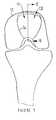
- the prosthesis 16is shown implanted on a left femur 12.
- the prosthesis 16 as shown in FIG. 3is a portion of a patella femoral joint 60.
- the patella femoral joint (PFJ) 60is used to replace the natural patella when the portion of the knee joint requires a prosthesis due to rheumatoid or osteoarthritis for example.
- the patella femoral joint 60may include a patella component 62 as well as a patella bearing 64, which is placed between the patella component 62, and the prosthesis or trochlear component 16.
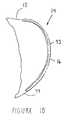
- the trochlear component 16 of the patella femoral joint 60is likewise asymmetrical including a smaller medial portion 66, as well as a larger lateral portion 70.
- the PFJ trochlear component 16defines an outer periphery 72 thereof.
- the trochlear implant periphery 72is slightly smaller than periphery 36 of the bone cavity 14. It should be appreciated that the trochlear prosthesis for the right knee is similar and complimentary to the left knee trochlear prosthesis 60 as shown in FIG. 13.
- the proper position of the trochlear prosthesis 60 with regard to the femur 12may be determined either by surgeon skill, by templating relative to anterior/posterior and medial/lateral x-ray techniques or by computer or other high technology positioning techniques.
- the guide 20must be properly secured in position on the femur 12.
- a trochlear component drilling guide 74 as shown in FIGS. 15 and 16may be utilized.
- the drilling guide 74 of FIGS. 15 and 16has been utilized in higher art implanting techniques.
- the drilling guide 74when used in prior art implanting techniques, is utilized by first visually positioning the drilling guide 74 in a predetermined appropriate position.
- This drilling guidemay include, among other things, surgeon expertise and x-ray templating.
- the drilling guide 74is positioned in its proper place against femur 12 and held in position while a drill is utilized to form anchor peg holes 76 in the femur 12.
- a scribe or edgeis formed around outer periphery 80 of the drilling guide 74 so that the scribed portion of the femur may be resected by prior art techniques utilizing for example osteotomes.
- the guide 20may include a first orientation feature for cooperation with an orientation feature on the prosthesis.
- the orientation feature on the prosthesismay be in the form of a peg 82 extending inwardly from inner periphery 46 of the guide 20.
- the first orientation feature or guide peg 82 of the guidecooperates with an orientation feature on the bone 12 in the form of, for example, one of the anchor peg holes 76.
- the guide peg 82closely conforms to the anchor peg 76 for an accurate, precise, and snug fit of the guide to the bone 12.
- a solitary peg 82may be sufficient to orient the guide 20 against the bone 12, preferably, and referring to FIG. 4, a pair of guide pegs 82, which are spaced apart from each other are utilized in the guide 20. While the prosthesis 16 of FIG. 4 includes two spaced apart anchor pegs 84, it would be appreciated that additional guide pegs 82 may be utilized to secure the guide 20 of FIG. 2.
- the rotatable tool 22is shown according to the present invention.
- the rotatable tool 22is adapted for removal of bone 12 from a patient to prepare the bone cavity 14 for receiving joint prosthesis 16.
- the tool 22is constrainable by the guide 20 for removal of the bone 12.
- the rotatable toolmay be in the form of a rotating burr tool.
- the tool 22may include the body 50, which includes cutting edge 52 formed on a periphery thereof.
- a stem 86is operably associated with the body 50.
- the stop 54is positioned between the body 50 and the stem 86 for cooperation with the guide 20 to limit the movement of the tool 22 in the direction of the arrow 56.
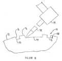
- FIGS. 7 through 10the bone cavity 14 prepared utilizing the tool guide kit and method of the present invention is shown on a left femur.
- the partially completed cavity 14includes medial and lateral arcuate periphery grooves 90 which correspond to the arcuate periphery channels 32 of the guide 20.
- the partially completed cavity 14further includes lower periphery grooves 92 corresponding to the lower periphery channels 34 of the guide 20.
- the cavity 14may include internal grooves 94 which correspond to the internal channels 42 of the guide 20. Located between the grooves 90, 92 and 94 are lands 96 corresponding to lands 40 of the guide 20.
- a second tool in the form of a chisel like device called an osteotome 98is shown in use to remove the lands 96 from the femur 12.
- a striking device in the form of a hammer 99may be utilized to remove bone with the osteotome 98.
- the osteotomeis positioned in one of the grooves, for example, groove 94 and the hammer 98 is struck against the osteotome 98 to remove for example, the land 96 between the peripheral grove 90 and the internal groove 94.
- the femuris shown with the cavity 14 having been completed, and the lands 96 between the grooves 90, 92 and 94 (See FIG. 7) having been removed.
- the cavity 14has the outer periphery 36 into which the prosthesis 16 may be fitted.
- the cavity 14also has a cavity depth CD which is approximately equal to the groove depth GD (see FIG. 8) formed by the tool when making the grooves 90, 92 and 94 in the femur 12. It should be appreciated that the groove depth GD is approximately equal to the depth TT of the tool 22 in the guide 20 as shown in FIG. 2.
- the cavity 14is shown in cross section in the femur 12.
- the prosthesis 16is shown in phantom within the cavity 14. It should be appreciated that the surface 93 of the prosthesis 16 is in general alignment with outer periphery 44 of the femur 12.
- kit 110includes a guide 120, which cooperates with a tool 122.
- the tool 122is similar to tool 22 of FIGS. 1 through 6 and includes a stem 186 to which stop 154 is attached. Extending from the stop 154 is a body 150. At the end of body 150 is a cutting edge 152 for removing bone 12.
- the tool 122may be substantially similar to the tool 22 of FIGS. 1 through 6 and be made of any suitable, durable material for example a tool steel.
- the guide 120is similar to guide 20 of FIGS. 1 through 6 except that guide 120 includes guide openings 176 and do not include guide pegs 82 as in the guide 20 of FIGS. 1 through 6.
- the kit 110 of FIGS. 17 and 18further include guide pins 182 which cooperate with the guide openings 176 of the guide 120 (see FIG. 18).
- the guide 120When utilizing the guide 120 of FIGS. 17 and 18, the guide 120, like the drilling guide 74 of FIGS. 15 and 16, is positioned utilizing any suitable surgical technique including, for example, a visual alignment of the guide 120 onto the femur or through the utilization of templates, for example, x-ray templates, a computer technique, or any other alignment technique.
- the guide pins 182Once the guide 120 is placed in the proper position on the femur, the guide pins 182 are placed in position through the guide openings 176 in the guide 120.
- the guide pins 182may be in the form of self drilling pins or connectors and a power tool (not shown) is utilized to secure the connectors or self drilling pins 118 and 128 into the femur 12. The guide 120 is thereby secured in position in the femur 12.
- the anchor peg holes 76are left in a unused or unworn condition so that the drilling guide 74 may be installed into the bone cavity 14 after the bone cavity 14 is prepared such that the anchor peg hole 76 remain in pristine condition for an accurate and secure installation of the prosthesis 16.
- Channels 130are preferably positioned in the guide 120, and the channels 130 include upper arcuate periphery channels 132 and lower periphery channels 134 which, when utilized with the tool 120, may cause the tool 122 to form periphery 36 of the cavity 14.
- the channels 130preferably also include internal channels 142, similar to channels 42 of the guide 20 of FIGS. 1 through 6.
- the upper arcuate periphery channels 132 and the lower periphery channels 134are similar to the upper arcuate channels 32 and the lower periphery channels 34 of the guide 20 of FIGS. 1 through 6.
- a femur 12having a partially formed bone cavity 14 formed on the femur 12 utilizing the guide 120 of FIGS. 17 and 18.
- the cavity 14includes arcuate periphery grooves 190 and lower periphery grooves 192, which correspond to the upper arcuate channels 132 and lower arcuate channels 134.
- the cavity 14also includes internal grooves 194 which correspond to internal channels 142 in the guide 120.
- Lands 196 in the cavity 14correspond to lands 140 on the guide 120 of FIGS. 17 and 18. Similar to the cavity 14 formed by the guide 20 of FIGS. 1 through 6, the lands 196 are similarly removed by an osteotome and hammer (not shown).
- kit 210includes a cutting tool guide 220 which cooperates with a cutting tool 222.
- the cutting tool 222is similar tool 22 of FIGS. 1-6 and may include a stem 286 to which a stop 254 is attached. Extending from the stop 254, is a body 250. At the end of the body 250 is a cutting edge 252 for removing bone.
- the tool 222may be substantially similar to the tool 22 of FIGS. 1-6 and be made of any suitable, durable material, for example a tool steel.
- the cutting tool guide 220is similar to guide 20 of FIGS. 1-6 except that cutting tool guide 220 includes guide openings 276 and does not include guide pegs 82 as in the guide of FIGS. 1-6.
- the kit 210 of FIGS. 21-23further includes a guide pin 282 which cooperates with the guide opening 276 of the guide 220.
- the guide 220When utilizing the cutting tool guide 220 of FIG. 21, the guide 220, like the drilling guide 74 of FIGS. 15 and 16, is positioned utilizing any suitable surgical technique including, for example, a visual alignment of the guide 220 onto the femur or the utilization of templates, for example, x-ray templates, a computer technique, or any other alignment technique.
- a visual alignment of the guide 220 onto the femuror the utilization of templates, for example, x-ray templates, a computer technique, or any other alignment technique.
- one or more guide pins 282are placed in position through the guide openings 276 in the cutting tool guide 220.
- the guide pins 282may be in the form of self drilling pins or connectors and a power tool (not shown) is utilized to secure the connectors or self drilling pins 218, 219 and 228 into the femur 12.
- the cutting tool guide 220is thereby secured in position into the femur.
- the cutting tool guide 220includes an outer periphery 221 thereof as well as an upper surface 223.
- the stop 254 of the tool 222is brought to rest against the upper surface 223 of the cutting tool guide 220 and limits the depth of the cut on the femur.
- the body 250 of the tool 222is guided along outer periphery 221 of the cutting tool guide 220 and is used to form outer periphery groove 290 in the femur 12.
- the kit 210further includes a drill guide 221 which cooperates with drill 223.
- the drill 223is similar 222 of FIGS. 1-6 and includes a stem 289 to which stop 255 is attached. Extending from the stop 255 is a body 251. At the end of the body 251 is a cutting edge 253 for removal bone 12.
- the drill 223may be substantially similar to the tool 222 of FIGS. 1-6 and may be made of any suitable durable material, for example, a tool steel.
- the drill guide 221is similar to the guide 20 of FIGS. 1-6 except that the drill guide 221 includes drill openings 277 and does not include guide pegs 82 as in the guide 20 of FIGS. 1-6.
- the drill guide 221 of FIG. 22includes a body 219 as well as a peripheral rim 230 extending around the periphery of the body 219.
- the peripheral rim 230can fit within outer periphery groove 290 formed by the tool 222 as the tool 222 is moved about the outer periphery 221 of the cutting tool guide 220. (See FIG.21 ).
- the drill openings 227are positioned in the body 219 of the drill guide 221 in a spaced apart relationship with as many drill openings 227 as reasonably can be placed in the body 219 while maintaining the necessary physical integrity of the drill guide 221.
- the drill openings 277typically have a drill diameter DD which provides for cooperation with diameter DD of the drill 223.
- the drill openings 277each have an identical drilled diameter DD.
- the drill 223has a drill length DL from the stop 255 of the drill 223 to the cutting edge 253 of the drill 223 which preferably is similar to the guide length GL from the upper surface 271 of the guide 221 through the face surface 273 of the cut in the femur for receiving the trochlear prosthesis 16(see FIGS. 10-12).
- the upper surfaces 271 of the drill guides 221are located on a plurality of planes such that the base surface 273 may be arcuate as shown in FIG.23.
- a femur 12is shown with the peripheral groove 290 formed in the femur 12 as well as the drilled holes 280 which were placed in the femur 12 utilizing the drill guide 221 in cooperation with drill 223 of the FIGS. 22 and 22A, respectively.
- the drilled holes 280are positioned as close as reasonable can be obtained realizing the limits of the drill guide 221.
- the kit 210preferably includes a tool, for example, an osteotome, (not shown) which may be utilized to remove material between the drill holes 280 and the peripheral grooves 290 such that a cavity 14 similar to that is shown in FIG. 10 is formed in the femur 12.
- the cavity 14is utilized to receive the prosthesis 16.
- the methodincludes a first step 210 of providing a guide for finding an opening in the guide.
- the methodalso includes a second step 212 of exposing a portion of the bone of the patient.
- the processfurther includes a third step 214 of placing the guide in cooperation with the patient.
- the methodfurther includes a fourth step 216 of providing a tool adapted for cooperation with the opening.
- the methodfurther includes a fifth step 220 of inserting the tool at least partially within the opening.
- the methodfurther includes a sixth step 222 of causing the tool to move relatively to the guide.
- the methodfurther includes a seventh step 224 of advancing the tool within the opening to form the bone cavity.
- the step 224 of advancing the tool within the opening to form the bone cavitymay include the steps of advancing the tool within the opening to form a portion of the bone cavity, providing a second tool and advancing the second tool within the opening to form the remainder of the bone cavity.
- the method of removal of bone from a patientmay be such that providing a tool step 216 may include advancing the tool within the opening to form a portion of the bone cavity; and the method may further include the steps of providing a second guide defining an opening in the second guide, placing the second guide in cooperation with the patient, inserting the tool at least partially within the opening, causing the tool to move relatively to the guide and advancing the tool within the opening to form the remainder of the bone cavity.
Landscapes
- Health & Medical Sciences (AREA)
- Surgery (AREA)
- Life Sciences & Earth Sciences (AREA)
- Biomedical Technology (AREA)
- Medical Informatics (AREA)
- Orthopedic Medicine & Surgery (AREA)
- Oral & Maxillofacial Surgery (AREA)
- Engineering & Computer Science (AREA)
- Dentistry (AREA)
- Heart & Thoracic Surgery (AREA)
- Nuclear Medicine, Radiotherapy & Molecular Imaging (AREA)
- Molecular Biology (AREA)
- Animal Behavior & Ethology (AREA)
- General Health & Medical Sciences (AREA)
- Public Health (AREA)
- Veterinary Medicine (AREA)
- Surgical Instruments (AREA)
- Prostheses (AREA)
Abstract
Description
The present invention relates generally to the field of orthopaedics, and moreparticularly, to an implant for use in arthroplasty.
Joint replacement surgery is quite common and it enables many individuals tofunction properly when it would not otherwise be possible to do so. Such patients of jointreplacement surgery typically suffer from osteoarthritis or rheumatoid arthritis. Artificialjoints usually comprise metallic, ceramic and/or plastic components that are fixed toexisting bone.
Such joint replacement surgery is otherwise known as total joint arthroplasty.Total joint arthroplasty is a well known surgical procedure by which a diseased and/ordamaged joint is replaced with a prosthetic joint. In a typical total joint arthroplasty, theadjacent ends of the bones and cartilage comprising the joint are resected and the artificialimplants are secured thereto.
When only one part of the knee joint is damaged, only the damaged compartmentis resected and replaced. This is known as a uni-compartmental knee joint arthroplasty.
When only the patellar articular surface and the adjacent groove on the distal endof the femur, the trochlear, with which it articulates, are damaged, replacement of thesesurfaces is called a patello femoral arthroplasty.
Frequently, when installing the components of the prosthetic joint, cartilage andbone must be resected or removed such that the implanted prosthesis has the same surfaceprofile as the surface prior to its resection. Such arthroplasty thus requires a pocket formedin the bone of a particular shape and depth to provide a location for the prosthesis such thatthe prosthesis outer-profile replicates that of the pre-resected joint. Among such joints forwhich a resected pocket is required is a trochlear implant for cooperation with a patellaprosthesis for a patello femoral arthroplasty.
The current process for preparing to implant a trochlear prosthesis is to place atemplate over the femur where the damaged trochlear is located. The trochlear groove ofthe femur is then physically marked with a tool such as a scribe or marking pen whichleaves a mark on the bone or cartilage as the scribe or pen is moved about the periphery ofthe template. The traced marks on the distal femur serve as a guide for preparing thepocket for the trochlear implant. Osteotomes and hammer plus high-speed rotating burrs are then used to prepare the pocket within the outlined perimeter. This process is very slowand tedious in order to achieve a precise and accurate fit in all dimensions.
A need thus exists for an improved method and instrumentation to assist in theimplanting of a trochlear prosthesis or similar implants, which are placed in the bone at adepth to conform to the pre-resected contour of the bone.
The present invention is directed to a cutting guide, which is utilized with arotating cutting tool to create pockets at a specific depth in the bone for a trochlear orsimilar implant. The cutting guide provides an accurate cut both in the outline shape and inthe depth of the cut. Additional cutting paths are made inside the outline shape utilizingthe cutting tool so that only a minimal amount of material must be removed between thecutting path.
According to one embodiment of the present invention, a kit for removal ofcartilage and bone from a patient to prepare a cavity for receiving a joint prosthesis isprovided. The kit includes a guide for cooperation with the bone and a rotatable tool. Thetool is constrainable by the guide for removal of the bone. The guide includes a firstportion thereof cooperable with the tool and a second portion thereof cooperable with thebone.
According to another embodiment of the present invention, a guide is provided forguiding a rotatable tool for removal of cartilage and bone from a patient to prepare a cavityfor receiving a joint prosthesis. The guide includes a first portion thereof cooperable withthe tool and a second portion cooperable with the bone.
According to yet another embodiment of the present invention, a rotatable tooladapted for removal of cartilage and bone from a patient to prepare a cavity for receiving ajoint prosthesis is provided. The tool is constrainable by the guide for removal of the bone.
According to a further embodiment of the present invention, a method for removalof cartilage and bone from a patient to prepare a cavity for receiving a joint prosthesis isprovided. The method includes the steps of providing a guide defining an opening therein,exposing a portion of the bone of the patient, placing the guide in cooperation with thebone, providing a tool adapted for cooperation with the opening, inserting the tool at leastpartially within the opening, causing the tool to move relatively to the guide, and advancingthe tool within the opening to form the bone cavity.
The technical advantage of the present invention includes an improved imprint orlocation of the pocket for the prosthesis. For example, according to one aspect of thepresent invention, the guide includes channels positioned about the outer periphery of theguide, which conform to the outer periphery of the pocket for placing the implant. The toolis moved about the pocket to provide for a pocket with an outer periphery that is welldefined and accurate. Thus, the present invention provides for an improved and accuratelocation of the pocket for the prosthesis.
Another technical advantage of the present invention includes an improvedaccuracy in the depth of the pocket into which the implant is to be located. For example,according to one aspect of the present invention, the tool includes a collar, whichcooperates with the guide when the tool is placed in the channels of the guide. The collaron the tool seats against the rim around the channels and provides for an accurate andconsistent depth of the pocket for the implant.
The technical advantages of the present invention further include the ability toform the pocket for an implant in much greater speed and precision. For example,according to one aspect of the present invention, the guide includes a plurality of spacedapart channels. These channels occupy most of the cross-sectional area of the guide. Theguide, in cooperation with the tool, is used to form most of the pocket for the implant.Only a quick and simple use of a small osteotome to remove the small portions of materialremaining after the utilization of the burr tool and guide, is required and that can be quicklyaccomplished. Therefore, with the rapid use of the guide and the burr tool and the minimaluse of the osteotome, the pocket may be prepared very quickly and accurately.
Embodiments of the invention will now be described by way of example withreference to the accompanying drawings, in which:
Referring to the drawings, FIG. 1 show akit 10 for removal ofbone 12, forexample, a portion of a long bone, from a patient to prepare abone cavity 14 for receivinga joint prosthesis 16 (see FIGS. 11-14), is shown.
Thekit 10 includes aguide 20 for cooperation with thelong bone 12. Thekit 10also includes aRotatable tool 22, which is constrained by theguide 20 for removal of thebone 12. Theguide 20 includes afirst portion 24 of theguide 20, which cooperates withthetool 22. Theguide 20 further includes asecond portion 26 of theguide 20, whichcooperates with thelong bone 12.
Preferably, and as shown in FIG. 1, thefirst portion 24 of theguide 20 defines achannel 30 through theguide 20. Thetool 22 is guidable within thechannel 30.Referring now to FIGS. 4, 5 and 6 theguide 20 is shown in greater detail.
Referring now to FIG. 6, thechannels 30 are shown onfirst portion 24 of theguide 20. As shown in FIG. 6, thechannels 30 may includearcuate periphery channels 32as well asLower periphery channels 34. Theperiphery channels periphery 36 of thebone cavity 12 as shown in phantom.
Theperiphery channels tool 22 in a path, whichcorresponds, toperiphery 36 of thebone cavity 12. To permit structural integrity to theguide 20, theperiphery channels 32 must be spaced from each other. The spacing providesfor support lands 40 which are positioned betweenadjacent periphery channels lands 40 provide for rigidity to theguide 20. It should be appreciated that uponutilization of theguide 20 and thetool 22, the portions of thebone 12 corresponding to thelands 40 on theguide 20 represent portions of the bone, which must be removed by anothertool (for example osteotome not shown).
According to the present invention, in addition toperiphery channels internal channels 42 may be positioned within theguide 20 to provide for removal ofadditional bone from thebone cavity 12 in an area within theperiphery 36 of thebonecavity 12. To provide for sufficient rigidity to theguide 20, theinternal channels 42 areseparated from each other.
Depending on the thickness ofguide 20 and the material chosen for themanufacture of theguide 20, it should be appreciated that the minimal acceptable distanceD between adjacent channels may vary. To minimize the amount of material to beremoved by the osteotome, the distance D should be the minimum distance required forsufficient strength of theguide 20. For example, for aguide 20 made of a durable material,such as, stainless steel, cobalt chrome or other suitable durable alloy metal having athickness T, of for example, 3.0 to 4.8 mm (0.12 to 0.19 inch) and for aguide 20 havingchannels 30 having a width W of, for example, 3.0 mm (0.12 inch) and for utilization with3.18 mm (⅛ inch) burr tool, the distanced may be as little as 1.0 mm (0.04 inch).
Referring again to FIGS. 1, 2 and 3, theguide 20 is shown in position againstbone 12. It should be appreciated that the tool, guide and kit of the present invention may beutilized to form a bone cavity in a bone in positions, in addition to the patella femoral jointdescribed in FIGS. 1-6. In fact, the guide and tool of the present invention may be utilizedto form any bone cavity, which may be necessary to provide a mounting location for aprosthetic implant.
The guide, tool and kit of the present invention is particularly well suited forutilization in a implant which has a generally uniform thickness and is designed to have anouter contour similar to that of the bone for which it replaces. For example, the tool guideand kit of the present invention may be well suited for unicondylar knee replacement inwhich a unicondylar knee having a generally uniform thickness is used to replace the resected bone. Other common joints particularly partial implants of the shoulder, knee orhip may be well suited to the use of the guide tool and kit of the present invention.
Referring again to FIGS. 1, 2 and 3, theguide 20 is preferably placed overouterperiphery 44 of thebone 12. As shown in FIGS. 1 through 6 thebone 12 is a femur and theguide 20 has aninner periphery 46 onsecond portion 26 of theguide 20, which preferablyconforms, closely toouter periphery 44 of thebone 12.
Referring now to FIG. 2, thetool 20 includes abody 50 including a cutting edge52 on an outer periphery thereof. Thebody 50 has a body diameter DD which is slidinglyfitted within thechannels 30 of theguide 20. The width W of thechannels 30 is thusslightly larger than the diameter DD of thebody 50. Thetool 22 preferably includes astop 54, which limits the motion of thetool 22 in the direction ofarrow 56 such that thestop 54rests against theguide 20.
The cutting edge 52 of thetool 22 extends inwardly frominner periphery 46 of theguide 20 a distance TT approximately equalled to the thickness TI of the implant (see FIG.12). Since theinner periphery 46 of theguide 20 is shaped to conform to theouterperiphery 44 of thebone 12, the extending of the tool 22 a distance TT below the innerperiphery of theguide 20 results in thebone cavity 14 to have a thickness or depthapproximately equal to TT.
Referring now to FIGS. 11 through 14,implant 16 is shown implanted intobonecavity 12. Theimplant 16 may be surgically implanted utilizing the tool guide and kit ofthe present invention. As stated earlier theimplant 16 may have any suitable shape andmay be an implant to replace any joint of the human anatomy or a portion of such a joint.Joints having a generally uniform thickness are particularly well suited for the presentinvention. Such joints may include unicondylar knee joints or patella femoral joint whichis shown in FIGS. 11 through 14.
Referring now to FIG. 13 theprosthesis 16 is shown implanted on aleft femur 12.Theprosthesis 16 as shown in FIG. 3 is a portion of a patella femoral joint 60. The patellafemoral joint (PFJ) 60 is used to replace the natural patella when the portion of the kneejoint requires a prosthesis due to rheumatoid or osteoarthritis for example. The patellafemoral joint 60 may include apatella component 62 as well as apatella bearing 64, whichis placed between thepatella component 62, and the prosthesis ortrochlear component 16.
Due to the unsymmetrical nature of theanatomical femur 12, thetrochlearcomponent 16 of the patella femoral joint 60 is likewise asymmetrical including a smallermedial portion 66, as well as a largerlateral portion 70. The PFJtrochlear component 16defines anouter periphery 72 thereof. Thetrochlear implant periphery 72, as shown inFIG. 13, is slightly smaller thanperiphery 36 of thebone cavity 14. It should beappreciated that the trochlear prosthesis for the right knee is similar and complimentary tothe left knee trochlear prosthesis 60 as shown in FIG. 13.
The proper position of the trochlear prosthesis 60 with regard to thefemur 12 maybe determined either by surgeon skill, by templating relative to anterior/posterior andmedial/lateral x-ray techniques or by computer or other high technology positioningtechniques. When the proper position of the PFJtrochlear component 16, with regard tothefemur 12 is determined, theguide 20 must be properly secured in position on thefemur 12.
When utilizing theguide 20 of FIGS. 1 through 6 a trochlear component drillingguide 74 as shown in FIGS. 15 and 16 may be utilized. The drilling guide 74 of FIGS. 15and 16 has been utilized in higher art implanting techniques. Thedrilling guide 74, whenused in prior art implanting techniques, is utilized by first visually positioning thedrillingguide 74 in a predetermined appropriate position.
Techniques utilized to position this drilling guide may include, among otherthings, surgeon expertise and x-ray templating. Thedrilling guide 74 is positioned in itsproper place againstfemur 12 and held in position while a drill is utilized to form anchorpeg holes 76 in thefemur 12. When utilizing prior art techniques for thedrilling guide 74,a scribe or edge is formed aroundouter periphery 80 of thedrilling guide 74 so that thescribed portion of the femur may be resected by prior art techniques utilizing for exampleosteotomes.
Referring now to FIGS. 1 through 6, to properly orient theguide 20 with respect tothefemur 12, theguide 20 may include a first orientation feature for cooperation with anorientation feature on the prosthesis. For example, and referring to FIG. 2, the orientationfeature on the prosthesis may be in the form of apeg 82 extending inwardly frominnerperiphery 46 of theguide 20. The first orientation feature or guidepeg 82 of the guidecooperates with an orientation feature on thebone 12 in the form of, for example, one of the anchor peg holes 76. Preferably, theguide peg 82 closely conforms to theanchor peg 76 for an accurate, precise, and snug fit of the guide to thebone 12.
While asolitary peg 82 may be sufficient to orient theguide 20 against thebone 12, preferably, and referring to FIG. 4, a pair of guide pegs 82, which are spaced apart fromeach other are utilized in theguide 20. While theprosthesis 16 of FIG. 4 includes twospaced apart anchor pegs 84, it would be appreciated that additional guide pegs 82 may beutilized to secure theguide 20 of FIG. 2.
Referring again to FIG. 2, therotatable tool 22 is shown according to the presentinvention. Therotatable tool 22 is adapted for removal ofbone 12 from a patient toprepare thebone cavity 14 for receivingjoint prosthesis 16. Thetool 22 is constrainable bytheguide 20 for removal of thebone 12.
As shown in FIG. 2 the rotatable tool may be in the form of a rotating burr tool.Thetool 22 may include thebody 50, which includes cutting edge 52 formed on aperiphery thereof. Astem 86 is operably associated with thebody 50. Thestop 54 ispositioned between thebody 50 and thestem 86 for cooperation with theguide 20 to limitthe movement of thetool 22 in the direction of thearrow 56.
Referring now to FIGS. 7 through 10 thebone cavity 14 prepared utilizing the toolguide kit and method of the present invention is shown on a left femur.
Referring now to FIG. 7, partially formed or completedcavity 14 is shown on thefemur 12. The partially completedcavity 14 includes medial and lateralarcuate peripherygrooves 90 which correspond to thearcuate periphery channels 32 of theguide 20. Thepartially completedcavity 14 further includeslower periphery grooves 92 corresponding tothelower periphery channels 34 of theguide 20. Further, thecavity 14 may includeinternal grooves 94 which correspond to theinternal channels 42 of theguide 20. Locatedbetween thegrooves lands 96 corresponding tolands 40 of theguide 20.
Referring now to FIG. 8, a second tool in the form of a chisel like device called anosteotome 98 is shown in use to remove thelands 96 from thefemur 12. A striking devicein the form of ahammer 99 may be utilized to remove bone with the osteotome 98. Inoperation, the osteotome is positioned in one of the grooves, for example, groove 94 andthe hammer 98 is struck against the osteotome 98 to remove for example, theland 96between theperipheral grove 90 and the internal groove 94.
Referring now to FIG. 9, the femur is shown with thecavity 14 having beencompleted, and thelands 96 between thegrooves cavity 14 has theouter periphery 36 into which theprosthesis 16 may befitted. Thecavity 14 also has a cavity depth CD which is approximately equal to thegroove depth GD (see FIG. 8) formed by the tool when making thegrooves femur 12. It should be appreciated that the groove depth GD is approximately equalto the depth TT of thetool 22 in theguide 20 as shown in FIG. 2.
Referring now to FIG. 10 thecavity 14 is shown in cross section in thefemur 12.Theprosthesis 16 is shown in phantom within thecavity 14. It should be appreciated thatthesurface 93 of theprosthesis 16 is in general alignment withouter periphery 44 of thefemur 12.
Referring now to FIGS. 17 and 18 another embodiment of the present indention isshown as kit 110. The kit 110 includes aguide 120, which cooperates with atool 122.Thetool 122 is similar totool 22 of FIGS. 1 through 6 and includes astem 186 to whichstop 154 is attached. Extending from thestop 154 is abody 150. At the end ofbody 150 isacutting edge 152 for removingbone 12. Thetool 122 may be substantially similar to thetool 22 of FIGS. 1 through 6 and be made of any suitable, durable material for example atool steel.
Theguide 120 is similar to guide 20 of FIGS. 1 through 6 except thatguide 120includesguide openings 176 and do not include guide pegs 82 as in theguide 20 of FIGS. 1through 6. The kit 110 of FIGS. 17 and 18 further include guide pins 182 which cooperatewith theguide openings 176 of the guide 120 (see FIG. 18).
When utilizing theguide 120 of FIGS. 17 and 18, theguide 120, like thedrillingguide 74 of FIGS. 15 and 16, is positioned utilizing any suitable surgical techniqueincluding, for example, a visual alignment of theguide 120 onto the femur or through theutilization of templates, for example, x-ray templates, a computer technique, or any otheralignment technique. Once theguide 120 is placed in the proper position on the femur, theguide pins 182 are placed in position through theguide openings 176 in theguide 120. Theguide pins 182 may be in the form of self drilling pins or connectors and a power tool (notshown) is utilized to secure the connectors or self drilling pins 118 and 128 into thefemur 12. Theguide 120 is thereby secured in position in thefemur 12.
By utilizing theguide apparatus 176 and the guide pins 182 the anchor peg holes76 are left in a unused or unworn condition so that thedrilling guide 74 may be installedinto thebone cavity 14 after thebone cavity 14 is prepared such that theanchor peg hole 76remain in pristine condition for an accurate and secure installation of theprosthesis 16.
Referring now to FIG. 19, afemur 12 is shown having a partially formedbonecavity 14 formed on thefemur 12 utilizing theguide 120 of FIGS. 17 and 18. Thecavity 14 includesarcuate periphery grooves 190 and lower periphery grooves 192, whichcorrespond to the upperarcuate channels 132 and lowerarcuate channels 134. Thecavity 14 also includesinternal grooves 194 which correspond to internal channels 142 in theguide 120.Lands 196 in thecavity 14 correspond to lands 140 on theguide 120 of FIGS.17 and 18. Similar to thecavity 14 formed by theguide 20 of FIGS. 1 through 6, thelands 196 are similarly removed by an osteotome and hammer (not shown).
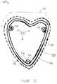
Referring now to FIGS. 21 through 23, a further embodiment of the presentinvention is shown askit 210. Thekit 210 includes acutting tool guide 220 whichcooperates with acutting tool 222. Thecutting tool 222 issimilar tool 22 of FIGS. 1-6 andmay include astem 286 to which astop 254 is attached. Extending from thestop 254, is abody 250. At the end of thebody 250 is acutting edge 252 for removing bone. Thetool 222 may be substantially similar to thetool 22 of FIGS. 1-6 and be made of any suitable,durable material, for example a tool steel.
Thecutting tool guide 220 is similar to guide 20 of FIGS. 1-6 except thatcuttingtool guide 220 includesguide openings 276 and does not include guide pegs 82 as in theguide of FIGS. 1-6. Thekit 210 of FIGS. 21-23 further includes aguide pin 282 whichcooperates with the guide opening 276 of theguide 220.
When utilizing thecutting tool guide 220 of FIG. 21, theguide 220, like thedrilling guide 74 of FIGS. 15 and 16, is positioned utilizing any suitable surgical technique including, for example, a visual alignment of theguide 220 onto the femur or theutilization of templates, for example, x-ray templates, a computer technique, or any otheralignment technique. Once theguide 220 is placed in the proper position on the femur, oneor more guide pins 282 are placed in position through theguide openings 276 in thecuttingtool guide 220. The guide pins 282 may be in the form of self drilling pins or connectorsand a power tool (not shown) is utilized to secure the connectors or self drilling pins 218,219 and 228 into thefemur 12. Thecutting tool guide 220 is thereby secured in positioninto the femur.
Thecutting tool guide 220 includes anouter periphery 221 thereof as well as anupper surface 223. Thestop 254 of thetool 222 is brought to rest against theupper surface 223 of thecutting tool guide 220 and limits the depth of the cut on the femur. Thebody 250 of thetool 222 is guided alongouter periphery 221 of thecutting tool guide 220 and isused to formouter periphery groove 290 in thefemur 12.
Referring now to FIG. 22, thekit 210 further includes adrill guide 221 whichcooperates withdrill 223. Thedrill 223 is similar 222 of FIGS. 1-6 and includes astem 289 to which stop 255 is attached. Extending from thestop 255 is abody 251. At the endof thebody 251 is acutting edge 253 forremoval bone 12. Thedrill 223 may besubstantially similar to thetool 222 of FIGS. 1-6 and may be made of any suitable durablematerial, for example, a tool steel.
Thedrill guide 221 is similar to theguide 20 of FIGS. 1-6 except that thedrillguide 221 includesdrill openings 277 and does not include guide pegs 82 as in theguide 20 of FIGS. 1-6. Thedrill guide 221 of FIG. 22 includes abody 219 as well as aperipheralrim 230 extending around the periphery of thebody 219. Preferably, theperipheral rim 230 can fit withinouter periphery groove 290 formed by thetool 222 as thetool 222 ismoved about theouter periphery 221 of thecutting tool guide 220. (See FIG.21 ).
Referring to FIGS. 22 and 23, the drill openings 227 are positioned in thebody 219 of thedrill guide 221 in a spaced apart relationship with as many drill openings 227 asreasonably can be placed in thebody 219 while maintaining the necessary physicalintegrity of thedrill guide 221. Thedrill openings 277 typically have a drill diameter DDwhich provides for cooperation with diameter DD of thedrill 223. Preferably in order thatasolitary drill 223 may be utilized, thedrill openings 277 each have an identical drilleddiameter DD.
Preferably, as is shown in FIGS. 22A and 23, thedrill 223 has a drill length DLfrom thestop 255 of thedrill 223 to thecutting edge 253 of thedrill 223 which preferablyis similar to the guide length GL from theupper surface 271 of theguide 221 through theface surface 273 of the cut in the femur for receiving the trochlear prosthesis 16(see FIGS.10-12). Preferably and as shown in FIG.23, theupper surfaces 271 of the drill guides 221are located on a plurality of planes such that thebase surface 273 may be arcuate as shownin FIG.23.
Referring now to FIG. 24, afemur 12 is shown with theperipheral groove 290formed in thefemur 12 as well as the drilledholes 280 which were placed in thefemur 12utilizing thedrill guide 221 in cooperation withdrill 223 of the FIGS. 22 and 22A,respectively. As can be seen from FIG. 24, the drilledholes 280 are positioned as close asreasonable can be obtained realizing the limits of thedrill guide 221.
As with thekit 10 of FIGS. 1-9, and as with the kit 110 of FIGS. 17 and 18, thekit 210, preferably includes a tool, for example, an osteotome, (not shown) which may beutilized to remove material between the drill holes 280 and theperipheral grooves 290 suchthat acavity 14 similar to that is shown in FIG. 10 is formed in thefemur 12. Thecavity 14 is utilized to receive theprosthesis 16.
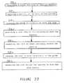
Referring now to FIG. 20, a method for removal of bone from a patient to preparea bone cavity for receiving prosthesis, is shown. The method includes afirst step 210 ofproviding a guide for finding an opening in the guide. The method also includes a secondstep 212 of exposing a portion of the bone of the patient. The process further includes athird step 214 of placing the guide in cooperation with the patient. The method furtherincludes a fourth step 216 of providing a tool adapted for cooperation with the opening.The method further includes afifth step 220 of inserting the tool at least partially within theopening. The method further includes asixth step 222 of causing the tool to moverelatively to the guide. The method further includes a seventh step 224 of advancing thetool within the opening to form the bone cavity.
The step 224 of advancing the tool within the opening to form the bone cavitymay include the steps of advancing the tool within the opening to form a portion of thebone cavity, providing a second tool and advancing the second tool within the opening toform the remainder of the bone cavity.
The method of removal of bone from a patient, according to the present invention,may be such that providing a tool step 216 may include advancing the tool within theopening to form a portion of the bone cavity; and the method may further include the stepsof providing a second guide defining an opening in the second guide, placing the secondguide in cooperation with the patient, inserting the tool at least partially within the opening,causing the tool to move relatively to the guide and advancing the tool within the openingto form the remainder of the bone cavity.
Claims (20)
- A kit for removal of bone from a patient to prepare a bone cavity forreceiving a joint prosthesis, said kit comprising:a guide for cooperation with the bone; anda rotatable tool constrainable by said guide for removal of the bone, said guideincluding a first portion thereof cooperable with said tool and a second portion thereofcooperable with the bone.
- The kit of claim 1 wherein the first portion of said guide defines achannel therethrough, said tool guidable within the channel.
- The kit of claim 1, wherein said guide comprises a first orientationfeature for cooperation with an orientation feature on the prosthesis.
- The kit of claim 3, in which the second portion of said guide defines aguide aperture therethrough; and which includes connector, which can cooperate with theaperture to form the first orientation feature.
- The kit of claim 3, wherein said first orientation feature comprises anexternal protrusion cooperable with a cavity in the bone.
- The kit of claim 3, in which the first orientation feature is defined by anopening said guide, and which includes a self drilling pin which can fit within the openingand cooperate with the bone to form a cavity therein.
- The kit of claim 2, wherein the channel has a generally arcuate shape.
- The kit of claim 2, in which the first mentioned channel is adapted forcooperation with the tool for removal of a first portion of bone adjacent a first portion ofthe prosthesis, and which includes a second channel adapted for cooperation with the toolfor removal of a second portion of bone adjacent a second portion of the prosthesis.
- The kit of claim 8, further comprising a second tool to remove bonebetween the first mentioned channel and the second channel.
- A guide for guiding a rotatable tool for removal of bone from a patient toprepare a bone cavity for receiving a joint prosthesis, said guide including a first portionthereof cooperable with said tool and a second portion cooperable with the bone.
- The guide of claim 10, wherein the first portion of said guide defines achannel therethrough, the tool guidable within the channel.
- The guide of claim 10, further comprising a first orientation feature forcooperation with an orientation feature on the bone.
- The guide of claim 10, in which the second portion of said guide definesa guide aperture therethrough, and which includes a connector which can cooperate withthe aperture to form the first orientation feature.
- The guide of claim 10, wherein said first orientation feature comprises anexternal protrusion cooperable with a cavity in the bone.
- The guide of claim 10, in which the first orientation feature is defined byan opening said guide, and which includes a self drilling pin which can fit within theopening and cooperate with the bone to form a cavity therein.
- The guide of claim 11, wherein the channel has a generally arcuate shape.
- The guide of claim 10, wherein said second portion defines a firstchannel for cooperation with the tool to form a portion of the periphery of the bone cavityand a second channel for cooperation with the tool to remove bone spaced from and withinthe periphery of the bone cavity.
- A rotatable tool adapted for removal of bone from a patient to prepare abone cavity for receiving a joint prosthesis, said tool constrainable by the guide for removalof the bone.
- The tool of claim 18, wherein the tool is a rotating burr tool.
- The tool of claim 19, wherein the tool comprises:a body including a cutting edge formed thereon;a stem operably associated with the body; anda stop positioned between the body and the stem for cooperation with the guide tolimit the movement of the tool in the direction of the guide.
Applications Claiming Priority (2)
| Application Number | Priority Date | Filing Date | Title |
|---|---|---|---|
| US10/176,891US8211113B2 (en) | 2002-06-21 | 2002-06-21 | Prosthesis cutting guide, cutting tool and method |
| US176891 | 2002-06-21 |
Publications (2)
| Publication Number | Publication Date |
|---|---|
| EP1374782A2true EP1374782A2 (en) | 2004-01-02 |
| EP1374782A3 EP1374782A3 (en) | 2004-11-17 |
Family
ID=29717849
Family Applications (1)
| Application Number | Title | Priority Date | Filing Date |
|---|---|---|---|
| EP03253924AWithdrawnEP1374782A3 (en) | 2002-06-21 | 2003-06-20 | Prosthesis cutting guide and cutting tool |
Country Status (3)
| Country | Link |
|---|---|
| US (1) | US8211113B2 (en) |
| EP (1) | EP1374782A3 (en) |
| AU (1) | AU2003204786B2 (en) |
Cited By (27)
| Publication number | Priority date | Publication date | Assignee | Title |
|---|---|---|---|---|
| WO2010014808A3 (en)* | 2008-08-01 | 2010-03-25 | Depuy Products, Inc. | Orthopaedic surgical instrumentation and method for performing a patellofemoral arthroplasty procedure |
| WO2011059641A1 (en)* | 2009-10-29 | 2011-05-19 | Zimmer, Inc. | Patient-specific mill guide |
| US8142510B2 (en) | 2007-03-30 | 2012-03-27 | Depuy Products, Inc. | Mobile bearing assembly having a non-planar interface |
| US8147557B2 (en) | 2007-03-30 | 2012-04-03 | Depuy Products, Inc. | Mobile bearing insert having offset dwell point |
| US8147558B2 (en) | 2007-03-30 | 2012-04-03 | Depuy Products, Inc. | Mobile bearing assembly having multiple articulation interfaces |
| US8328874B2 (en) | 2007-03-30 | 2012-12-11 | Depuy Products, Inc. | Mobile bearing assembly |
| US8728084B2 (en) | 2011-06-27 | 2014-05-20 | Biomet Sports Medicine, Llc | Apparatus for repairing bone defects |
| FR2998469A1 (en)* | 2012-11-28 | 2014-05-30 | Philippe Champion | Femoral preparation ancillary for e.g. preparing distal part of femur for establishment of total prosthesis of knee, has channel for passing guide between anterior and distal faces such that punch cuts portion of distal part of femur |
| US8764841B2 (en) | 2007-03-30 | 2014-07-01 | DePuy Synthes Products, LLC | Mobile bearing assembly having a closed track |
| US8870884B2 (en) | 2011-06-27 | 2014-10-28 | Biomet Sports Medicine, Llc | Method for repairing bone defects |
| EP2400930A4 (en)* | 2009-02-25 | 2014-12-17 | Arthrosurface Inc | TROCHLEAR SURFACE SYSTEM AND METHOD |
| US9044343B2 (en) | 2002-12-03 | 2015-06-02 | Arthrosurface Incorporated | System for articular surface replacement |
| US9055955B2 (en) | 2000-05-01 | 2015-06-16 | Arthrosurface Inc. | Bone resurfacing system and method |
| US9066716B2 (en) | 2011-03-30 | 2015-06-30 | Arthrosurface Incorporated | Suture coil and suture sheath for tissue repair |
| US9662126B2 (en) | 2009-04-17 | 2017-05-30 | Arthrosurface Incorporated | Glenoid resurfacing system and method |
| US9861492B2 (en) | 2014-03-07 | 2018-01-09 | Arthrosurface Incorporated | Anchor for an implant assembly |
| US9931211B2 (en) | 2003-02-24 | 2018-04-03 | Arthrosurface Incorporated | Trochlear resurfacing system and method |
| US10045788B2 (en) | 2006-12-11 | 2018-08-14 | Arthrosurface Incorporated | Retrograde resection apparatus and method |
| US10307172B2 (en) | 2012-07-03 | 2019-06-04 | Arthrosurface Incorporated | System and method for joint resurfacing and repair |
| US10624752B2 (en) | 2006-07-17 | 2020-04-21 | Arthrosurface Incorporated | Tibial resurfacing system and method |
| US10624748B2 (en) | 2014-03-07 | 2020-04-21 | Arthrosurface Incorporated | System and method for repairing articular surfaces |
| US10695096B2 (en) | 2013-04-16 | 2020-06-30 | Arthrosurface Incorporated | Suture system and method |
| US10945743B2 (en) | 2009-04-17 | 2021-03-16 | Arthrosurface Incorporated | Glenoid repair system and methods of use thereof |
| US11160663B2 (en) | 2017-08-04 | 2021-11-02 | Arthrosurface Incorporated | Multicomponent articular surface implant |
| US11478358B2 (en) | 2019-03-12 | 2022-10-25 | Arthrosurface Incorporated | Humeral and glenoid articular surface implant systems and methods |
| US11607319B2 (en) | 2014-03-07 | 2023-03-21 | Arthrosurface Incorporated | System and method for repairing articular surfaces |
| US11712276B2 (en) | 2011-12-22 | 2023-08-01 | Arthrosurface Incorporated | System and method for bone fixation |
Families Citing this family (52)
| Publication number | Priority date | Publication date | Assignee | Title |
|---|---|---|---|---|
| US20030055502A1 (en) | 2001-05-25 | 2003-03-20 | Philipp Lang | Methods and compositions for articular resurfacing |
| US8083745B2 (en) | 2001-05-25 | 2011-12-27 | Conformis, Inc. | Surgical tools for arthroplasty |
| US7468075B2 (en) | 2001-05-25 | 2008-12-23 | Conformis, Inc. | Methods and compositions for articular repair |
| US7534263B2 (en) | 2001-05-25 | 2009-05-19 | Conformis, Inc. | Surgical tools facilitating increased accuracy, speed and simplicity in performing joint arthroplasty |
| US7618451B2 (en) | 2001-05-25 | 2009-11-17 | Conformis, Inc. | Patient selectable joint arthroplasty devices and surgical tools facilitating increased accuracy, speed and simplicity in performing total and partial joint arthroplasty |
| US7239908B1 (en) | 1998-09-14 | 2007-07-03 | The Board Of Trustees Of The Leland Stanford Junior University | Assessing the condition of a joint and devising treatment |
| WO2000035346A2 (en) | 1998-09-14 | 2000-06-22 | Stanford University | Assessing the condition of a joint and preventing damage |
| US6712856B1 (en)* | 2000-03-17 | 2004-03-30 | Kinamed, Inc. | Custom replacement device for resurfacing a femur and method of making the same |
| US6610067B2 (en) | 2000-05-01 | 2003-08-26 | Arthrosurface, Incorporated | System and method for joint resurface repair |
| US6520964B2 (en) | 2000-05-01 | 2003-02-18 | Std Manufacturing, Inc. | System and method for joint resurface repair |
| ATE426357T1 (en) | 2000-09-14 | 2009-04-15 | Univ Leland Stanford Junior | ASSESSING THE CONDITION OF A JOINT AND PLANNING TREATMENT |
| DE60136474D1 (en) | 2000-09-14 | 2008-12-18 | Univ R | ASSESSMENT OF THE CONDITION OF A JOINT AND LOSS OF CARTEL TISSUE |
| GB0029317D0 (en)* | 2000-12-01 | 2001-01-17 | Afriat Jacques | A template for a modular joint prosthesis component |
| US8439926B2 (en) | 2001-05-25 | 2013-05-14 | Conformis, Inc. | Patient selectable joint arthroplasty devices and surgical tools |
| US8366713B2 (en) | 2003-03-31 | 2013-02-05 | Depuy Products, Inc. | Arthroplasty instruments and associated method |
| US8545506B2 (en)* | 2003-03-31 | 2013-10-01 | DePuy Synthes Products, LLC | Cutting guide for use with an extended articulation orthopaedic implant |
| US7517364B2 (en) | 2003-03-31 | 2009-04-14 | Depuy Products, Inc. | Extended articulation orthopaedic implant and associated method |
| US8105327B2 (en) | 2003-03-31 | 2012-01-31 | Depuy Products, Inc. | Punch, implant and associated method |
| US7828853B2 (en) | 2004-11-22 | 2010-11-09 | Arthrosurface, Inc. | Articular surface implant and delivery system |
| WO2006127486A2 (en)* | 2005-05-20 | 2006-11-30 | Smith & Nephew, Inc. | Patello-femoral joint implant and instrumentation |
| US8273088B2 (en)* | 2005-07-08 | 2012-09-25 | Depuy Spine, Inc. | Bone removal tool |
| CN105030296A (en) | 2006-02-06 | 2015-11-11 | 康复米斯公司 | Patient selectable joint arthroplasty devices and surgical tools |
| US8623026B2 (en) | 2006-02-06 | 2014-01-07 | Conformis, Inc. | Patient selectable joint arthroplasty devices and surgical tools incorporating anatomical relief |
| US7758651B2 (en)* | 2006-10-18 | 2010-07-20 | Howmedica Osteonics Corp. | Mis patellar preparation |
| US7582118B2 (en)* | 2007-02-06 | 2009-09-01 | Zimmer Technology, Inc. | Femoral trochlea prostheses |
| WO2008157412A2 (en) | 2007-06-13 | 2008-12-24 | Conformis, Inc. | Surgical cutting guide |
| EP3610809B1 (en)* | 2009-01-23 | 2021-07-14 | Synthes GmbH | Jig and saw guides for use in osteotomies |
| WO2010099123A2 (en) | 2009-02-24 | 2010-09-02 | Mako Surgical Corp. | Prosthetic device, method of planning bone removal for implantation of prosthetic device, and robotic system |
| US12383287B2 (en) | 2009-02-24 | 2025-08-12 | Microport Orthopedics Holdings, Inc. | Systems and methods for installing an orthopedic implant |
| US8808297B2 (en) | 2009-02-24 | 2014-08-19 | Microport Orthopedics Holdings Inc. | Orthopedic surgical guide |
| US8808303B2 (en) | 2009-02-24 | 2014-08-19 | Microport Orthopedics Holdings Inc. | Orthopedic surgical guide |
| US9017334B2 (en) | 2009-02-24 | 2015-04-28 | Microport Orthopedics Holdings Inc. | Patient specific surgical guide locator and mount |
| US8480753B2 (en)* | 2009-02-27 | 2013-07-09 | Howmedica Osteonics Corp. | Spot facing trochlear groove |
| US20100222782A1 (en)* | 2009-02-27 | 2010-09-02 | Howmedica Osteonics Corp. | Spot facing trochlear groove |
| SG10201401326SA (en) | 2009-04-16 | 2014-10-30 | Conformis Inc | Patient-specific joint arthroplasty devices for ligament repair |
| AU2010236182A1 (en) | 2009-04-17 | 2011-11-24 | Arthrosurface Incorporated | Glenoid resurfacing system and method |
| US9486226B2 (en) | 2012-04-18 | 2016-11-08 | Conformis, Inc. | Tibial guides, tools, and techniques for resecting the tibial plateau |
| US9675471B2 (en) | 2012-06-11 | 2017-06-13 | Conformis, Inc. | Devices, techniques and methods for assessing joint spacing, balancing soft tissues and obtaining desired kinematics for joint implant components |
| EP2872053A4 (en)* | 2012-07-15 | 2016-03-09 | Smith & Nephew Inc | INSTRUMENT ADAPTED TO A PATIENT |
| US9427334B2 (en)* | 2013-03-08 | 2016-08-30 | Stryker Corporation | Bone pads |
| US10667829B2 (en)* | 2013-08-21 | 2020-06-02 | Laboratoires Bodycad Inc. | Bone resection guide and method |
| US9173665B2 (en)* | 2013-09-06 | 2015-11-03 | Zimmer, Inc. | Patient-specific surgical guide for intra-operative production of patient-specific augment |
| US9655727B2 (en) | 2013-12-12 | 2017-05-23 | Stryker Corporation | Extended patellofemoral |
| EP3603579A1 (en) | 2014-05-12 | 2020-02-05 | Integra LifeSciences Corporation | Total ankle replacement prosthesis |
| US11266420B2 (en)* | 2014-08-06 | 2022-03-08 | Unik Orthopedics, Inc. | Sparse contact femoral jig mechanism |
| US20170330485A1 (en)* | 2014-10-08 | 2017-11-16 | Indian Council Of Medical Research | Neuro-drill-stencil trainer |
| US9999428B2 (en)* | 2015-06-30 | 2018-06-19 | DePuy Synthes Products, Inc. | Orthopaedic surgical instrument system and method for surgically preparing a patients bone |
| US11051829B2 (en)* | 2018-06-26 | 2021-07-06 | DePuy Synthes Products, Inc. | Customized patient-specific orthopaedic surgical instrument |
| EP3975939B1 (en) | 2019-05-29 | 2024-11-13 | Wright Medical Technology, Inc. | Device for preparing a tibia for receiving tibial implant component of a replacement ankle |
| WO2021146015A1 (en) | 2020-01-17 | 2021-07-22 | Wright Medical Technology, Inc. | Guidance tools, systems, and methods |
| US20230404705A1 (en)* | 2020-07-15 | 2023-12-21 | Daniel S. Kim | Guided implant drill system and methods of use |
| US20220015865A1 (en)* | 2020-07-15 | 2022-01-20 | Daniel S. Kim | Guided implant drill system and methods of use |
Family Cites Families (58)
| Publication number | Priority date | Publication date | Assignee | Title |
|---|---|---|---|---|
| US1723517A (en)* | 1924-04-28 | 1929-08-06 | Emerson C Mcfadden | Drafting instrument |
| US3943576A (en) | 1971-10-14 | 1976-03-16 | Sivash Konstantin Mitrofanovic | Artificial hip joint made from two different surgical alloys |
| US3820167A (en) | 1968-06-18 | 1974-06-28 | K Sivash | Artificial hip joint |
| US4077070A (en) | 1968-06-18 | 1978-03-07 | Sivash Konstantin Mitrofanovic | Artificial hip joint |
| CA962806A (en) | 1970-06-04 | 1975-02-18 | Ontario Research Foundation | Surgical prosthetic device |
| US3996625A (en) | 1975-02-28 | 1976-12-14 | United States Surgical Corporation | Artificial hip joint with novel stem |
| US4551863A (en) | 1981-09-28 | 1985-11-12 | Murray William M | Femoral component and method |
| US4567885A (en)* | 1981-11-03 | 1986-02-04 | Androphy Gary W | Triplanar knee resection system |
| US4524766A (en) | 1982-01-07 | 1985-06-25 | Petersen Thomas D | Surgical knee alignment method and system |
| US4530114A (en) | 1982-07-16 | 1985-07-23 | Slobodan Tepic | Total hip joint prostheses |
| US4672957A (en)* | 1983-10-04 | 1987-06-16 | South African Inventions Development Corporation | Surgical device |
| US4846839A (en) | 1984-02-09 | 1989-07-11 | Joint Medical Products Corporation | Apparatus for affixing a prosthesis to bone |
| US4721104A (en)* | 1985-12-02 | 1988-01-26 | Dow Corning Wright Corporation | Femoral surface shaping apparatus for posterior-stabilized knee implants |
| US4703751A (en)* | 1986-03-27 | 1987-11-03 | Pohl Kenneth P | Method and apparatus for resecting a distal femoral surface |
| US4790852A (en) | 1986-09-15 | 1988-12-13 | Joint Medical Products Corporation | Sleeves for affixing artificial joints to bone |
| US5002547A (en) | 1987-02-07 | 1991-03-26 | Pfizer Hospital Products Group, Inc. | Apparatus for knee prosthesis |
| FR2616059A1 (en) | 1987-06-05 | 1988-12-09 | Sorem Soc Realisa Elect Mec | Apparatus for reduction and/or containment of a fractured bone |
| US5306311A (en)* | 1987-07-20 | 1994-04-26 | Regen Corporation | Prosthetic articular cartilage |
| US5011496A (en) | 1988-02-02 | 1991-04-30 | Joint Medical Products Corporation | Prosthetic joint |
| US4865603A (en) | 1988-02-04 | 1989-09-12 | Joint Medical Products Corporation | Metallic prosthetic devices having micro-textured outer surfaces |
| US4979949A (en) | 1988-04-26 | 1990-12-25 | The Board Of Regents Of The University Of Washington | Robot-aided system for surgery |
| US5122144A (en)* | 1989-09-26 | 1992-06-16 | Kirschner Medical Corporation | Method and instrumentation for unicompartmental total knee arthroplasty |
| US5167619A (en) | 1989-11-17 | 1992-12-01 | Sonokineticss Group | Apparatus and method for removal of cement from bone cavities |
| US5246444A (en)* | 1990-01-08 | 1993-09-21 | Schreiber Saul N | Osteotomy device and method |
| US5035699A (en) | 1990-01-09 | 1991-07-30 | Dow Corning Wright | Patella track cutter and guide |
| US5053037A (en)* | 1991-03-07 | 1991-10-01 | Smith & Nephew Richards Inc. | Femoral instrumentation for long stem surgery |
| US5100408A (en)* | 1991-03-07 | 1992-03-31 | Smith & Nephew Richards Inc. | Femoral instrumentation for long stem surgery |
| US5344423A (en)* | 1992-02-06 | 1994-09-06 | Zimmer, Inc. | Apparatus and method for milling bone |
| GB9202561D0 (en)* | 1992-02-07 | 1992-03-25 | Howmedica | Orthopaedic instrument |
| US5295992A (en) | 1992-03-16 | 1994-03-22 | Othy, Inc. | Patella cutting system |
| US5326365A (en) | 1992-04-10 | 1994-07-05 | Alvine Franklin G | Ankle implant |
| US5190547A (en) | 1992-05-15 | 1993-03-02 | Midas Rex Pneumatic Tools, Inc. | Replicator for resecting bone to match a pattern |
| WO1994005211A1 (en) | 1992-09-09 | 1994-03-17 | Depuy Inc. | Bone cutting apparatus and method |
| US5312411A (en)* | 1992-10-27 | 1994-05-17 | Smith & Nephew Richards, Inc. | Uni-compartmental femoral knee instruments and prosthesis |
| DE69331586T2 (en) | 1992-11-20 | 2002-10-24 | Dennis W. Burke | IMPROVED FEMORAL CUFF IMPLANT |
| US5409489A (en) | 1993-01-12 | 1995-04-25 | Sioufi; Georges | Surgical instrument for cone-shaped sub-trochanteric rotational osteotomy |
| US5364402A (en)* | 1993-07-29 | 1994-11-15 | Intermedics Orthopedics, Inc. | Tibial spacer saw guide |
| US5908424A (en) | 1994-05-16 | 1999-06-01 | Zimmer, Inc, By Said Stalcup, Dietz, Bays And Vanlaningham | Tibial milling guide system |
| US5540692A (en) | 1994-07-13 | 1996-07-30 | Midas Rex Pneumatic Tools, Inc. | Replicator for resecting bone to match a pattern |
| US5534005A (en) | 1994-10-05 | 1996-07-09 | Smith & Nephew Richards, Inc. | Surgical milling system |
| US5910143A (en) | 1994-12-16 | 1999-06-08 | Exactech, Inc. | Intramedullary alignment guide tool |
| US5683397A (en)* | 1995-02-15 | 1997-11-04 | Smith & Nephew, Inc. | Distal femoral cutting guide apparatus for use in knee joint replacement surgery |
| US5593411A (en)* | 1995-03-13 | 1997-01-14 | Zimmer, Inc. | Orthopaedic milling guide for milling intersecting planes |
| US5766259A (en) | 1995-03-14 | 1998-06-16 | Sammarco; Giacomo J. | Total ankle prosthesis and method |
| US5634927A (en)* | 1995-07-06 | 1997-06-03 | Zimmer, Inc. | Sizing plate and drill guide assembly for orthopaedic knee instrumentation |
| US5613970A (en)* | 1995-07-06 | 1997-03-25 | Zimmer, Inc. | Orthopaedic instrumentation assembly having an offset bushing |
| US5601563A (en)* | 1995-08-25 | 1997-02-11 | Zimmer, Inc. | Orthopaedic milling template with attachable cutting guide |
| WO1997030648A1 (en)* | 1996-02-23 | 1997-08-28 | Midwest Orthopedic Research Foundation | Device and method for distal femur cutting and prothesis measuring |
| US5743910A (en) | 1996-11-14 | 1998-04-28 | Xomed Surgical Products, Inc. | Orthopedic prosthesis removal instrument |
| US6488687B1 (en)* | 1997-09-18 | 2002-12-03 | Medidea, Llc | Joint replacement method and apparatus |
| US5916220A (en)* | 1998-02-02 | 1999-06-29 | Medidea, Llc | Bone cutting guide and method to accommodate different-sized implants |
| AU755664B2 (en)* | 1998-06-29 | 2002-12-19 | Plus Endoprothetik Ag | Device and method for inserting a prosthetic knee |
| US6277121B1 (en) | 1998-09-09 | 2001-08-21 | Brian D. Burkinshaw | Patella reaming system |
| US6106529A (en) | 1998-12-18 | 2000-08-22 | Johnson & Johnson Professional, Inc. | Epicondylar axis referencing drill guide |
| US6321457B1 (en)* | 1999-02-24 | 2001-11-27 | Richard L. Lariviere, Jr. | Cutting template and method of using same |
| US6342057B1 (en)* | 2000-04-28 | 2002-01-29 | Synthes (Usa) | Remotely aligned surgical drill guide |
| US6355045B1 (en)* | 2000-12-28 | 2002-03-12 | Depuy Orthopaedics, Inc. | Method and apparatus for surgically preparing a tibia for implantation of a prosthetic implant component which has an offset stem |
| US6554838B2 (en)* | 2001-05-31 | 2003-04-29 | Howmedica Osteonics Corp. | Method and apparatus for implanting a prosthetic device |
- 2002
- 2002-06-21USUS10/176,891patent/US8211113B2/ennot_activeExpired - Fee Related
- 2003
- 2003-06-19AUAU2003204786Apatent/AU2003204786B2/ennot_activeExpired
- 2003-06-20EPEP03253924Apatent/EP1374782A3/ennot_activeWithdrawn
Cited By (51)
| Publication number | Priority date | Publication date | Assignee | Title |
|---|---|---|---|---|
| US9055955B2 (en) | 2000-05-01 | 2015-06-16 | Arthrosurface Inc. | Bone resurfacing system and method |
| US10076343B2 (en) | 2002-12-03 | 2018-09-18 | Arthrosurface Incorporated | System for articular surface replacement |
| US9044343B2 (en) | 2002-12-03 | 2015-06-02 | Arthrosurface Incorporated | System for articular surface replacement |
| US10624749B2 (en) | 2003-02-24 | 2020-04-21 | Arthrosurface Incorporated | Trochlear resurfacing system and method |
| US9931211B2 (en) | 2003-02-24 | 2018-04-03 | Arthrosurface Incorporated | Trochlear resurfacing system and method |
| US11337819B2 (en) | 2003-02-24 | 2022-05-24 | Arthrosurface Incorporated | Trochlear resurfacing system and method |
| US11471289B2 (en) | 2006-07-17 | 2022-10-18 | Arthrosurface Incorporated | Tibial resurfacing system and method |
| US10624752B2 (en) | 2006-07-17 | 2020-04-21 | Arthrosurface Incorporated | Tibial resurfacing system and method |
| US10045788B2 (en) | 2006-12-11 | 2018-08-14 | Arthrosurface Incorporated | Retrograde resection apparatus and method |
| US10959740B2 (en) | 2006-12-11 | 2021-03-30 | Arthrosurface Incorporated | Retrograde resection apparatus and method |
| US8328874B2 (en) | 2007-03-30 | 2012-12-11 | Depuy Products, Inc. | Mobile bearing assembly |
| US8764841B2 (en) | 2007-03-30 | 2014-07-01 | DePuy Synthes Products, LLC | Mobile bearing assembly having a closed track |
| US8147558B2 (en) | 2007-03-30 | 2012-04-03 | Depuy Products, Inc. | Mobile bearing assembly having multiple articulation interfaces |
| US8147557B2 (en) | 2007-03-30 | 2012-04-03 | Depuy Products, Inc. | Mobile bearing insert having offset dwell point |
| US8142510B2 (en) | 2007-03-30 | 2012-03-27 | Depuy Products, Inc. | Mobile bearing assembly having a non-planar interface |
| EP2407115A3 (en)* | 2008-08-01 | 2012-05-02 | DePuy Products, Inc. | Orthopaedic surgical instrumentation and method for performing a patellofemoral arthroplasty procedure |
| US8920427B2 (en) | 2008-08-01 | 2014-12-30 | DePuy Synthes Products, LLC | Orthopaedic surgical method for performing a patellofemoral arthroplasty procedure |
| WO2010014808A3 (en)* | 2008-08-01 | 2010-03-25 | Depuy Products, Inc. | Orthopaedic surgical instrumentation and method for performing a patellofemoral arthroplasty procedure |
| US11000297B2 (en) | 2008-08-01 | 2021-05-11 | DePuy Synthes Products, Inc. | Orthopaedic surgical instrumentation for performing a patellofemoral arthroplasty procedure |
| US8828016B2 (en) | 2008-08-01 | 2014-09-09 | DePuy Synthes Products, LLC | Orthopaedic surgical instrumentation for performing a patellofemoral arthroplasty procedure |
| US12185957B2 (en) | 2008-08-01 | 2025-01-07 | DePuy Synthes Products, Inc. | Orthopaedic surgical instrumentation for performing a patellofemoral arthroplasty procedure |
| US9895156B2 (en) | 2008-08-01 | 2018-02-20 | DePuy Synthes Products, Inc. | Orthopaedic surgical instrumentation for performing a patellofemoral arthroplasty procedure |
| EP2400930A4 (en)* | 2009-02-25 | 2014-12-17 | Arthrosurface Inc | TROCHLEAR SURFACE SYSTEM AND METHOD |
| US10945743B2 (en) | 2009-04-17 | 2021-03-16 | Arthrosurface Incorporated | Glenoid repair system and methods of use thereof |
| US10478200B2 (en) | 2009-04-17 | 2019-11-19 | Arthrosurface Incorporated | Glenoid resurfacing system and method |
| US9662126B2 (en) | 2009-04-17 | 2017-05-30 | Arthrosurface Incorporated | Glenoid resurfacing system and method |
| US11478259B2 (en) | 2009-04-17 | 2022-10-25 | Arthrosurface, Incorporated | Glenoid resurfacing system and method |
| US9839434B2 (en) | 2009-10-29 | 2017-12-12 | Zimmer, Inc. | Patient-specific mill guide |
| WO2011059641A1 (en)* | 2009-10-29 | 2011-05-19 | Zimmer, Inc. | Patient-specific mill guide |
| US9066716B2 (en) | 2011-03-30 | 2015-06-30 | Arthrosurface Incorporated | Suture coil and suture sheath for tissue repair |
| US9693786B2 (en) | 2011-06-27 | 2017-07-04 | Biomet Sports Medicine, Llc | Method for repairing bone defects |
| US8728084B2 (en) | 2011-06-27 | 2014-05-20 | Biomet Sports Medicine, Llc | Apparatus for repairing bone defects |
| US8870884B2 (en) | 2011-06-27 | 2014-10-28 | Biomet Sports Medicine, Llc | Method for repairing bone defects |
| US9301766B2 (en) | 2011-06-27 | 2016-04-05 | Biomet Sports Medicine, Llc | Apparatus for repairing bone defects |
| US11712276B2 (en) | 2011-12-22 | 2023-08-01 | Arthrosurface Incorporated | System and method for bone fixation |
| US10307172B2 (en) | 2012-07-03 | 2019-06-04 | Arthrosurface Incorporated | System and method for joint resurfacing and repair |
| US11191552B2 (en) | 2012-07-03 | 2021-12-07 | Arthrosurface, Incorporated | System and method for joint resurfacing and repair |
| FR2998469A1 (en)* | 2012-11-28 | 2014-05-30 | Philippe Champion | Femoral preparation ancillary for e.g. preparing distal part of femur for establishment of total prosthesis of knee, has channel for passing guide between anterior and distal faces such that punch cuts portion of distal part of femur |
| US10695096B2 (en) | 2013-04-16 | 2020-06-30 | Arthrosurface Incorporated | Suture system and method |
| US11648036B2 (en) | 2013-04-16 | 2023-05-16 | Arthrosurface Incorporated | Suture system and method |
| US10624748B2 (en) | 2014-03-07 | 2020-04-21 | Arthrosurface Incorporated | System and method for repairing articular surfaces |
| US9931219B2 (en) | 2014-03-07 | 2018-04-03 | Arthrosurface Incorporated | Implant and anchor assembly |
| US10624754B2 (en) | 2014-03-07 | 2020-04-21 | Arthrosurface Incorporated | System and method for repairing articular surfaces |
| US10575957B2 (en) | 2014-03-07 | 2020-03-03 | Arthrosurface Incoporated | Anchor for an implant assembly |
| US11607319B2 (en) | 2014-03-07 | 2023-03-21 | Arthrosurface Incorporated | System and method for repairing articular surfaces |
| US11083587B2 (en) | 2014-03-07 | 2021-08-10 | Arthrosurface Incorporated | Implant and anchor assembly |
| US9861492B2 (en) | 2014-03-07 | 2018-01-09 | Arthrosurface Incorporated | Anchor for an implant assembly |
| US11766334B2 (en) | 2014-03-07 | 2023-09-26 | Arthrosurface Incorporated | System and method for repairing articular surfaces |
| US9962265B2 (en) | 2014-03-07 | 2018-05-08 | Arthrosurface Incorporated | System and method for repairing articular surfaces |
| US11160663B2 (en) | 2017-08-04 | 2021-11-02 | Arthrosurface Incorporated | Multicomponent articular surface implant |
| US11478358B2 (en) | 2019-03-12 | 2022-10-25 | Arthrosurface Incorporated | Humeral and glenoid articular surface implant systems and methods |
Also Published As
| Publication number | Publication date |
|---|---|
| US20030236521A1 (en) | 2003-12-25 |
| AU2003204786A1 (en) | 2004-01-22 |
| US8211113B2 (en) | 2012-07-03 |
| AU2003204786B2 (en) | 2009-05-21 |
| EP1374782A3 (en) | 2004-11-17 |
Similar Documents
| Publication | Publication Date | Title |
|---|---|---|
| US8211113B2 (en) | Prosthesis cutting guide, cutting tool and method | |
| US12185957B2 (en) | Orthopaedic surgical instrumentation for performing a patellofemoral arthroplasty procedure | |
| US9579110B2 (en) | Patient selectable joint arthroplasty devices and surgical tools | |
| EP1738720B1 (en) | Systems for use in knee replacement surgery | |
| US7258701B2 (en) | Systems and methods for compartmental replacement in a knee | |
| US20200390452A1 (en) | Patient Selectable Joint Arthroplasty Devices and Surgical Tools | |
| EP3181068B1 (en) | Custom replacement device for resurfacing a femur | |
| AU730146B2 (en) | Bone cutting guides for use in the implantation of prosthetic joint components | |
| US7172597B2 (en) | Provisional orthopedic implant and recutting instrument guide | |
| US6589248B1 (en) | Patellar alignment device | |
| EP1374783B1 (en) | Prosthesis cavity cutting guide and cutting tool | |
| US20170164957A1 (en) | Patient Selectable Joint Arthroplasty Devices and Surgical Tools | |
| EP2265199A1 (en) | Patient selectable joint arthroplasty devices and surgical tools | |
| EP2958522B1 (en) | Anatomically guided instrumentation for trochlear groove replacement | |
| AU2003204784B2 (en) | Prosthesis removal cutting guide, cutting tool and method | |
| CN116784926A (en) | Patient specific apparatus with medial offset and related methods |
Legal Events
| Date | Code | Title | Description |
|---|---|---|---|
| PUAI | Public reference made under article 153(3) epc to a published international application that has entered the european phase | Free format text:ORIGINAL CODE: 0009012 | |
| AK | Designated contracting states | Kind code of ref document:A2 Designated state(s):AT BE BG CH CY CZ DE DK EE ES FI FR GB GR HU IE IT LI LU MC NL PT RO SE SI SK TR | |
| AX | Request for extension of the european patent | Extension state:AL LT LV MK | |
| PUAL | Search report despatched | Free format text:ORIGINAL CODE: 0009013 | |
| AK | Designated contracting states | Kind code of ref document:A3 Designated state(s):AT BE BG CH CY CZ DE DK EE ES FI FR GB GR HU IE IT LI LU MC NL PT RO SE SI SK TR | |
| AX | Request for extension of the european patent | Extension state:AL LT LV MK | |
| 17P | Request for examination filed | Effective date:20050509 | |
| AKX | Designation fees paid | Designated state(s):AT BE BG CH CY CZ DE DK EE ES FI FR GB GR HU IE IT LI LU MC NL PT RO SE SI SK TR | |
| STAA | Information on the status of an ep patent application or granted ep patent | Free format text:STATUS: THE APPLICATION IS DEEMED TO BE WITHDRAWN | |
| 18D | Application deemed to be withdrawn | Effective date:20110408 |