EP1369094B1 - Implant and method of manufacturing a sterile packaged implant - Google Patents
Implant and method of manufacturing a sterile packaged implantDownload PDFInfo
- Publication number
- EP1369094B1 EP1369094B1EP02012124.0AEP02012124AEP1369094B1EP 1369094 B1EP1369094 B1EP 1369094B1EP 02012124 AEP02012124 AEP 02012124AEP 1369094 B1EP1369094 B1EP 1369094B1
- Authority
- EP
- European Patent Office
- Prior art keywords
- implant
- recess
- accordance
- positioning location
- projection
- Prior art date
- Legal status (The legal status is an assumption and is not a legal conclusion. Google has not performed a legal analysis and makes no representation as to the accuracy of the status listed.)
- Expired - Lifetime
Links
- 239000007943implantSubstances0.000titleclaimsdescription94
- 238000004519manufacturing processMethods0.000titledescription2
- 230000001954sterilising effectEffects0.000claimsdescription57
- 238000004659sterilization and disinfectionMethods0.000claimsdescription51
- 239000004699Ultra-high molecular weight polyethyleneSubstances0.000claimsdescription17
- 229920000785ultra high molecular weight polyethylenePolymers0.000claimsdescription17
- 229910052751metalInorganic materials0.000claimsdescription16
- 239000002184metalSubstances0.000claimsdescription16
- 238000004806packaging method and processMethods0.000claimsdescription14
- 239000000463materialSubstances0.000claimsdescription11
- 238000004873anchoringMethods0.000claimsdescription10
- IAYPIBMASNFSPL-UHFFFAOYSA-NEthylene oxideChemical compoundC1CO1IAYPIBMASNFSPL-UHFFFAOYSA-N0.000claimsdescription9
- 238000003780insertionMethods0.000claimsdescription9
- 230000037431insertionEffects0.000claimsdescription9
- 238000000034methodMethods0.000claimsdescription9
- RTAQQCXQSZGOHL-UHFFFAOYSA-NTitaniumChemical compound[Ti]RTAQQCXQSZGOHL-UHFFFAOYSA-N0.000claimsdescription6
- 239000010936titaniumSubstances0.000claimsdescription6
- 229910052719titaniumInorganic materials0.000claimsdescription6
- 239000012528membraneSubstances0.000claimsdescription4
- 244000005700microbiomeSpecies0.000claimsdescription3
- 229920003023plasticPolymers0.000claimsdescription3
- 239000004033plasticSubstances0.000claimsdescription3
- 238000003860storageMethods0.000claimsdescription3
- 230000007704transitionEffects0.000claimsdescription2
- 239000007789gasSubstances0.000description45
- 238000005553drillingMethods0.000description8
- 238000003825pressingMethods0.000description6
- 210000000988bone and boneAnatomy0.000description5
- 210000004394hip jointAnatomy0.000description5
- 238000005299abrasionMethods0.000description4
- 230000000295complement effectEffects0.000description4
- 238000004132cross linkingMethods0.000description4
- 238000006073displacement reactionMethods0.000description4
- 238000002513implantationMethods0.000description3
- 230000003716rejuvenationEffects0.000description3
- 229920010741Ultra High Molecular Weight Polyethylene (UHMWPE)Polymers0.000description2
- 210000000588acetabulumAnatomy0.000description2
- 239000002131composite materialSubstances0.000description2
- 230000000694effectsEffects0.000description2
- 238000010438heat treatmentMethods0.000description2
- 230000036512infertilityEffects0.000description2
- 230000000399orthopedic effectEffects0.000description2
- 241001433879CamareaSpecies0.000description1
- 208000003076OsteolysisDiseases0.000description1
- 239000004698PolyethyleneSubstances0.000description1
- 229910001069Ti alloyInorganic materials0.000description1
- 230000002411adverseEffects0.000description1
- 239000000560biocompatible materialSubstances0.000description1
- 239000002639bone cementSubstances0.000description1
- 229910010293ceramic materialInorganic materials0.000description1
- 238000010276constructionMethods0.000description1
- 238000011109contaminationMethods0.000description1
- 229920003020cross-linked polyethylenePolymers0.000description1
- 239000004703cross-linked polyethyleneSubstances0.000description1
- 238000005520cutting processMethods0.000description1
- 210000003709heart valveAnatomy0.000description1
- 210000001624hipAnatomy0.000description1
- 230000005865ionizing radiationEffects0.000description1
- 230000007774longtermEffects0.000description1
- 208000029791lytic metastatic bone lesionDiseases0.000description1
- 238000012423maintenanceMethods0.000description1
- 230000005499meniscusEffects0.000description1
- ORQBXQOJMQIAOY-UHFFFAOYSA-NnobeliumChemical compound[No]ORQBXQOJMQIAOY-UHFFFAOYSA-N0.000description1
- 230000003647oxidationEffects0.000description1
- 238000007254oxidation reactionMethods0.000description1
- 239000002245particleSubstances0.000description1
- 230000002093peripheral effectEffects0.000description1
- -1polyethylenePolymers0.000description1
- 229920000573polyethylenePolymers0.000description1
- 230000005855radiationEffects0.000description1
- 230000002787reinforcementEffects0.000description1
- 238000009738saturatingMethods0.000description1
- 239000007787solidSubstances0.000description1
- 238000001356surgical procedureMethods0.000description1
- 229910052715tantalumInorganic materials0.000description1
- GUVRBAGPIYLISA-UHFFFAOYSA-Ntantalum atomChemical compound[Ta]GUVRBAGPIYLISA-UHFFFAOYSA-N0.000description1
- 231100000331toxicToxicity0.000description1
- 230000002588toxic effectEffects0.000description1
- 239000002341toxic gasSubstances0.000description1
Images


Classifications
- A—HUMAN NECESSITIES
- A61—MEDICAL OR VETERINARY SCIENCE; HYGIENE
- A61L—METHODS OR APPARATUS FOR STERILISING MATERIALS OR OBJECTS IN GENERAL; DISINFECTION, STERILISATION OR DEODORISATION OF AIR; CHEMICAL ASPECTS OF BANDAGES, DRESSINGS, ABSORBENT PADS OR SURGICAL ARTICLES; MATERIALS FOR BANDAGES, DRESSINGS, ABSORBENT PADS OR SURGICAL ARTICLES
- A61L2/00—Methods or apparatus for disinfecting or sterilising materials or objects other than foodstuffs or contact lenses; Accessories therefor
- A61L2/16—Methods or apparatus for disinfecting or sterilising materials or objects other than foodstuffs or contact lenses; Accessories therefor using chemical substances
- A61L2/20—Gaseous substances, e.g. vapours
- A61L2/206—Ethylene oxide
- A—HUMAN NECESSITIES
- A61—MEDICAL OR VETERINARY SCIENCE; HYGIENE
- A61L—METHODS OR APPARATUS FOR STERILISING MATERIALS OR OBJECTS IN GENERAL; DISINFECTION, STERILISATION OR DEODORISATION OF AIR; CHEMICAL ASPECTS OF BANDAGES, DRESSINGS, ABSORBENT PADS OR SURGICAL ARTICLES; MATERIALS FOR BANDAGES, DRESSINGS, ABSORBENT PADS OR SURGICAL ARTICLES
- A61L27/00—Materials for grafts or prostheses or for coating grafts or prostheses
- A61L27/14—Macromolecular materials
- A61L27/16—Macromolecular materials obtained by reactions only involving carbon-to-carbon unsaturated bonds
- C—CHEMISTRY; METALLURGY
- C08—ORGANIC MACROMOLECULAR COMPOUNDS; THEIR PREPARATION OR CHEMICAL WORKING-UP; COMPOSITIONS BASED THEREON
- C08L—COMPOSITIONS OF MACROMOLECULAR COMPOUNDS
- C08L2207/00—Properties characterising the ingredient of the composition
- C08L2207/06—Properties of polyethylene
- C08L2207/068—Ultra high molecular weight polyethylene
- C—CHEMISTRY; METALLURGY
- C08—ORGANIC MACROMOLECULAR COMPOUNDS; THEIR PREPARATION OR CHEMICAL WORKING-UP; COMPOSITIONS BASED THEREON
- C08L—COMPOSITIONS OF MACROMOLECULAR COMPOUNDS
- C08L23/00—Compositions of homopolymers or copolymers of unsaturated aliphatic hydrocarbons having only one carbon-to-carbon double bond; Compositions of derivatives of such polymers
- C08L23/02—Compositions of homopolymers or copolymers of unsaturated aliphatic hydrocarbons having only one carbon-to-carbon double bond; Compositions of derivatives of such polymers not modified by chemical after-treatment
- C08L23/04—Homopolymers or copolymers of ethene
- C08L23/06—Polyethene
- C—CHEMISTRY; METALLURGY
- C08—ORGANIC MACROMOLECULAR COMPOUNDS; THEIR PREPARATION OR CHEMICAL WORKING-UP; COMPOSITIONS BASED THEREON
- C08L—COMPOSITIONS OF MACROMOLECULAR COMPOUNDS
- C08L2312/00—Crosslinking
Definitions
- the multipart implantis packaged in a predetermined pre-positioning position for the first element and then a gas sterilization is carried out while the first element is in the defined pre-positioning position, an extremely effective, full-surface sterilization of the multipart implant can be achieved.
- the sterilized implantis transported in this pre-assembled position in the package and stored until it is brought to the surgical field as needed, where it is available in the pre-assembled state after tearing the package.
- the points of contact between the first element and the second element in the recessmay be substantially punctiform.
- the size of the contact surfaces between the first and the second elementis minimized, so that taking into account the low relative mobility between the elements all Surfaces of the implant can be flowed around by the sterilization medium during the gas sterilization.
- the number of contact points in the recess between the first element and the second element in the Vorposition michswolfis kept low. This also means that the contact surface between the first and the second element is kept as small as possible, so that the implant can be optimally washed around by the sterilization medium.
- the first elementis held loosely in the Vorposition réelleswolf by means of a snap connection and in the Endposition réelleswolf with the second element in the press fit and / or by means of a snap connection non-positively and positively connected.
- the first elementcan be replaced by a simple displacement, such as a rotation and / or displacement are transferred from the Vorposition réelleswolf in the Endposition réelleswolf in which the first element is fixed in the second element.
- the first elementmay have at least one projection which engages in the second position in the final positioning position. This ensures a secure frictional and positive connection of the first element with the second element of the implant.
- the first elementmay be a ball or a pin, in particular a metal ball or a metal pin.
- X-ray contrast balls or pins in an implantcan be effectively sterilized with gas and reliably fixed in the implant prior to surgery.
- the first elementmay comprise a ball and a plug with a receptacle for the ball.
- the ballIn the pre-positioning position, the ball may be loosely held in the plug or between the plug and the recess, and in the final positioning position, the plug in the recess and the ball in the plug may be held non-positively and positively.
- tiny ballsfor example with a diameter of 2 mm, can be reliably sterilized together with the implant and reliably fixed in the implant intraoperatively. At the same time, the handling of the balls and their sterility during handling is simplified.
- the second elementmay be an inner shell of a joint prosthesis and the first element may be a cover plate of the inner shell.
- the recessmay be provided in the outer wall of the inner shell with a circular cross-section, a side wall and a bottom becoming deeper towards the center of the recess, the side wall having at least one retaining projection directed towards the center of the recess.
- the cover platemay be loosely held by the side wall and the projection and may have at least one cam on its outer periphery, which engages in the Endposition réelleswolf in the side wall of the recess clamped when the cover is displaced by a rotational movement from the Vorposition réelleswolf to the Endpositionberichtswolf.
- This constructionallows, for example, in a frusto-conical hip joint prosthesis shell with cover a highly effective sterilization with gas, since the cover is mounted in the Vorpositionleiterswolf with a sufficient clearance. Due to the bottom of the recess becoming deeper, the flat shape of the cover and the projection, the contact between the first element and the second element is kept small area. The gas reaches the ground through grooves that interrupt the sidewall and reach to the bottom. Thus, an all-round flow around the cover in the recess during gas sterilization is achieved. The at least one cam of the cover also ensures an extremely strong connection between the first and the second element in the Endposition réelleswolf.
- At least one receptacle for the cam in the Vorposition réelleswolf with gameIn the side wall of the recess can be provided at least one receptacle for the cam in the Vorposition réelleswolf with game. This makes it possible that the cam area is sufficiently flowed around during the gas sterilization in the Vorposition réelleswolf of the sterilization medium.
- the side wall of the recessmay have a guide, in particular a slide-in guide, for introducing the first element into the pre-positioning position. This facilitates the assembly of the first element in the second element prior to gas sterilization.
- the objectis also achieved by an arrangement of an implant and a packaging according to claim 22 and a method for providing an implant and a packaging according to claim 23, in particular by producing a sterilized packaged implant having at least one first element and one second element the elements forming the implant can be sterilized with gas in a mutually coupled, relative to each other game having Vorposition réelleswolf and can be introduced in this Vorposition réelleswolf into the actual surgical field.
- the gas sterilizationcan be carried out with ethylene oxide.
- the sterilely packaged in a Vorpositionleiterswolf individual elementscan be positively and non-positively connected to each other after opening the package by turning and / or sliding movements for final assembly of the implant.
- FIG. 1a and 1b shown in the Endpositionleiterswolf first embodiment of the implant according to the inventionconsists of a frusto-conical acetabulum shell 2 with an outer shell 4 made of titanium, an inner shell 6 of highly cross-linked ultra high molecular weight polyethylene (UHMWPE) and a cover plate 8 made of titanium.
- the hip joint prosthesis shell 2is designed as a hip socket, which is implanted without the use of bone cement. Openings 10 in the outer shell make it possible to control the seat of the shell in the bone and to fill any cavities with bone chips.
- the cover plate 8is provided from the biocompatible material titanium. This is located in a recess 12 of the inner shell and is centered in this recess 12.
- the outer shell 4has a cutting thread 14 for anchoring the acetabulum in the bone.
- holes 16are provided which serve for insertion of a tool.
- the inner shell 6is in the outer shell 4 by means of a snap connection 18, consisting of recesses on the inside of the outer shell 4 and projections on the outside of the inner shell 6, attached.
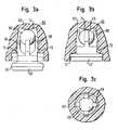
- Fig. 1ashows that the recess 12 has a sloping bottom 20 which is lowered to the center of the inner shell 6.
- the recess 12is bounded by a side wall 22, at the upper end approximately in a peripheral half of the recess, an inwardly directed projection 24 is provided. This projection 24 engages over the cover plate 8 when it is inserted from the opposite side of the projection 24 into the recess 12.
- Fig. 1bshows a perspective side view of the inner shell, in which the cover plate is not used.
- four radially offset grooves 30are provided in the side wall 22 and offset by 90 °.
- two insertion guides 32 for the cover plate 8are provided adjacent to the ends of the projection 24. The insertion guides 32 are designed such that they guide the cover plate 8 when inserted into the recess 12 under the projection 24.
- a circumferential groove 26is also provided in the transition between the side wall 22 and the bottom 20.
- the cover plate 8 which has just been formedhas an engagement cam 28 on its circumference. In Fig. 1a this is a cam 28 recognizable.
- the cover plate between the insertion guides 32is placed on the side wall 22 and inserted into the recess 12, wherein the cam 28 comes to rest in a groove 30.
- the cover plate 8is thereby pushed under the projection 24 in the recess 12 and then assumes the Vorposition réelleswolf, in which it is held loose by the projection 24.
- the dimensions of the recess 12, the presence of the groove 26 and the sloping bottom 20cause the cover plate 8 is supported in the recess on the one hand with a clearance of, for example, about 0.2 mm and on the other hand supported only small area.
- the cam 28 of the cover plateis loosely positioned in one of the grooves 30 of the side wall 22, i. it is the Vorposition réelleswolf ago.
- the Vorpositionierungs ein the cover plate 8is set before the sterilization of the inner shell with ethylene oxide at the manufacturer of the implant. Subsequently, the gas sterilization is carried out. Since in the Vorposition réelles ein the contact surfaces between the cover plate 8 and the inner shell 6 are kept in the recess 12 due to the low clearance and the sloping bottom 20 of the recess to a minimum, the ethylene oxide, taking into account the relative mobility of the items in the sterilization virtually all surfaces of the cover plate 8 and the inner shell 6 flow around. This enables extremely effective and safe gas sterilization.
- the X-ray contrast ball 40is radially and axially loosely mounted between the projections 46 and 48.
- the X-ray contrast ball 40 and the projections 46, 48only small areas of contact exist.
- between the ball 40 and the element 44is an all-round game, for example, about 0.2 mm.
- a separately supplied, sterile plug 52can be used, which is clamped in the Endposition réelleswolf via projections 48 and sealingly fixed in the bore 42.
- the plug 52has a length such that a flush closing of the plug 52 with the open end of the bore 42 indicates that the ball 40 is fixed in its intended end position.
- the bore 66has depressions 72 disposed in a ring around its circular periphery for receiving the projections 70 in the pre-positioning position.
- the borehas an inwardly bulging, closed end 74.
- end positionis adjusted by a displacement of the cup towards the closed end 74 of the bore from the Vorposition michswolf and is secured by a snap connection 61.
- the ball 60 and the cup 62is fixed at the end 74 of the bore non-positively and positively.
- the illustrated embodimentincludes an implant 84 of highly cross-linked UHMWPE having a bore 82 and a metal X-ray contrast pin 80.
- the bore 82has at its open end a region 87 with a large diameter. At the closed end of the bore 82, a region 89 is formed with a smaller diameter. The bore 82 further has between the region 87 and the region 89 a the tapered portion 88 and 89 in the area to the open end of the bore arranged annular retaining projection 90th
- the X-ray contrast pin 80has longitudinally extending teeth 92 distributed around the circumference of the pin.
- the pre-positioning positionis adjusted by inserting the pin 80 between the tapered portion 88 and the projection 90 of the bore at the manufacturer.
- the X-ray contrast pin 80is held axially with a clearance of 0.2 mm.
- the teeth 92radially center the pin within the large diameter portion 87 with a clearance of 0.2 mm.
- the points of contact of the tips of the teeth 92 with the inner wall of the bore 82are linear. As a result, all surfaces inside the bore 82 are effectively sterilized with gas.
- the sixth embodiment showncomprises a metal pin 108 and a UHMWPE element 100.
- the pin 108serves as a mechanical guide element to adjacent implant elements.
- the pin 108is anchored as a bolt in a movable tibial insert (gliding meniscus) of highly cross-linked UHMWPE for guiding against a tibial metal reinforcement.
- the pin 108has a tapered end 110 and an annular projection 116 disposed adjacent the tapered end 110.
- the projection 116 between the two rings of the projections 114is axially and radially kept in play.
- the conical end 110 of the pinis also mounted with a clearance in the region 106 of the bore.
- the contact points between the projections 114 and the pin 108are punctiform, as shown Fig. 6a is recognizable.
- the radial and axial play and the punctiform contact pointsensure that during sterilization virtually all surfaces within the bore 102 are flowed around by the sterilization gas.
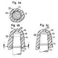
- the seventh embodiment showncomprises a metal pin 128 and a UHMWPE element 120.
- the pin 128has a conical end 130.
- the pin 128further includes adjacent to the conical end 130 two successively arranged recesses 138 and 140, which are each annularly inserted into the pin 128.
- the annular recess 138 disposed immediately behind the conical end 130 of the pinhas a contour adapted to projections 134 on the member 120, while the recess 140 is made larger in the longitudinal direction of the pin 128 as compared to the recess 138.
- Vorpositionierungswolfis set by the manufacturer before the gas sterilization by inserting the pin 128 into the bore 122.
- Fig. 7a and 7bshow the pin 128 in the pre-positioning position in which the pin 128 is loosely held by engaging the projections 134 with the recesses 138 with a radial and axial clearance of, for example, 0.2 mm. It is the conical end 130 of the pen also loosely received within the tapered region 126 of the bore. Out Fig. 7a It can be seen that between the protrusions 134 and the pin 128 only punctiform, playful points of contact exist.
- the pin 128After opening the package and shortly before inserting the implant 120, the pin 128 is moved from the pre-positioning position by pressing the pin into the bore in the in Fig. 7c fixed end position shown fixed. In this case, the conical end 130 of the pin sits in a clamping position in the region 126 of the bore non-positively and positively.
- Fig. 8a to 8cshow the implant according to the invention executed as a cone connection between an implant 150 with a bore 152 and a pin 154.
- the implant 150is made of highly cross-linked ultra-high molecular weight polyethylene, while the pin 154 is a metal pin.
- the snap spring 196 of the inner shellconsists of four, offset by 90 ° in a circle arranged resilient webs 200. On the outside of the webs 200, a projection 202 is provided at the free end of the webs in each case.
- the recess 198has at its open end around the circumference of the recess 198 around two mutually parallel, annular projections 206 and 208.
- the final positioning positionis realized by displacing the inner shell 192 from the pre-positioning position toward the outer shell 190, with the projection 202 of the snap spring pressed over the projection 206.
- the snap spring 196is almost completely inserted into the recess 198 and centers the inner shell 192 in the outer shell 190, wherein the projection 206 of the outer shell 190 positively engages in a corresponding recess 204 of the inner shell 192.
- the actual anchoring between outer and inner shelltakes place by a snap connection on the equator.
- Vorpositionierungswolfis set before performing a gas sterilization, in particular a sterilization with ethylene oxide.
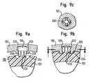
- the portion 224 of the pin between the tapered portion 220 and the projection 222 of the recessis arranged.
- an axial clearanceexists.
- the points of contactare punctiform in the prepositioned position between the teeth 228 and the implant 214.
- virtually all surfaces within the bore 216are gas-accessible during gas sterilization.
Landscapes
- Health & Medical Sciences (AREA)
- Chemical & Material Sciences (AREA)
- Animal Behavior & Ethology (AREA)
- Epidemiology (AREA)
- Life Sciences & Earth Sciences (AREA)
- Chemical Kinetics & Catalysis (AREA)
- General Health & Medical Sciences (AREA)
- Public Health (AREA)
- Veterinary Medicine (AREA)
- General Chemical & Material Sciences (AREA)
- Dermatology (AREA)
- Medicinal Chemistry (AREA)
- Oral & Maxillofacial Surgery (AREA)
- Transplantation (AREA)
- Prostheses (AREA)
Description
Translated fromGermanDie Erfindung betrifft ein Implantat, sowie ein Verfahren zum Bereitstellen einer Anordnung aus einem Implantat und einer Verpackung.The invention relates to an implant, as well as a method for providing an arrangement of an implant and a packaging.
Ultrahochmolekulares Polyethylen (UHMWPE) ist ein in der orthopädischen Endoprothetik verbreiteter Werkstoff, der sich als Gleitpartner gegenüber metallischen und keramischen Werkstoffen bewährt hat. Problematisch ist bei diesem Materialpaarungen der im Gebrauch unvermeidliche Abrieb und die dadurch ausgelöste partikelinduzierte Osteolyse, die schlimmstenfalls zu einer Lockerung des Implantats führen kann.Ultra-high molecular weight polyethylene (UHMWPE) is a widely used material in orthopedic endoprosthetics, which has proved to be a sliding partner in comparison with metallic and ceramic materials. The problem with this pair of materials is the unavoidable abrasion in use and the particle-induced osteolysis which is the result, which can lead to loosening of the implant in the worst case.
Eine geeignete Maßnahme zur Optimierung des UHMWPE mit dem Ziel der Reduktion des entstehenden Abriebs ist die Hochvernetzung. Diese wird durch Elektronen- oder Gammabestrahlung und eine Wärmebehandlung des Materials erreicht, wodurch das ultrahochmolekulare Polyethylen verschleißfest und langzeitstabil gemacht wird. Die Hochvernetzung erfolgt durch eine Vernetzung der UHMWPE-Molekülketten und durch eine Absättigung der freien Radikale.A suitable measure for optimizing the UHMWPE with the aim of reducing the resulting abrasion is the high-crosslinking. This is achieved by electron or gamma radiation and a heat treatment of the material, which makes the ultra-high molecular weight polyethylene wear-resistant and long-term stable. High crosslinking is achieved by crosslinking the UHMWPE molecular chains and by saturating the free radicals.
Die in der orthopädischen Endoprothetik übliche Sterilisationsmethode der Gammabestrahlung kann für hochvernetztes UHMWPE nicht angewendet werden, weil dadurch wieder unerwünschte freie Radikale entstehen würden. Diese begünstigen eine Oxidationswirkung und eine damit verbundene Versprödung des Materials. Daher wird hochvernetztes UHMWPE nicht mit ionisierender Strahlung, sondern mit Gas, beispielsweise mit Ethylenoxid oder Gas-Plasma, sterilisiert.The standard in orthopedic endoprosthetics sterilization method of gamma irradiation can not be used for highly cross-linked UHMWPE, because this would again create undesirable free radicals. These promote an oxidation effect and an associated embrittlement of the material. Therefore, highly cross-linked UHMWPE is not sterilized with ionizing radiation but with gas, for example with ethylene oxide or gas plasma.
Bei Implantatkomponenten, die ausschließlich aus hochvernetztem Polyethylen bestehen, werden mittels Hochvernetzung und Wärmebehandlung des UHMWPE-Rohlings, anschließender mechanischer Bearbeitung, Verpackung und Gassterilisation zufrieden stellende Ergebnisse erzielt.Implant components consisting exclusively of highly cross-linked polyethylene achieve satisfactory results by means of high-crosslinking and heat treatment of the UHMWPE blank, subsequent mechanical processing, packaging and gas sterilization.
Jedoch können Implantate aus mehreren, während des Herstellprozesses zusammengesetzten Elementen bestehen. Bei derartigen, zusammengesetzten Implantaten stellt sich die Problematik der wirksamen Sterilisation. Eine Sterilisation mit Gammastrahlen würde das gesamte Implantat erfassen und somit Elemente aus UHMWPE oxidieren. Eine Gassterilisation hingegen wirkt nur auf all diejenigen Oberflächen des Implantates, die für das Gas während der Sterilisation zugänglich sind. Um dabei auch durch Zusatzelemente abgedeckte Oberflächen für das Sterilisiergas zugänglich zu machen, ist es bekannt, die Verbindung von Implantatelementen mit Spiel vorzunehmen. Aufgrund klinischer Erfahrung ist jedoch ein solches Spiel problematisch, da auf diese Weise ermöglichte Mikrobewegungen von Implantatelementen im Verdacht stehen, unerwünschten Abrieb zu erzeugen und einem dauerhaften Anwachsen des Knochens entgegen zu wirken.However, implants may consist of several elements assembled during the manufacturing process. In such composite implants, the problem of effective sterilization arises. Sterilization with gamma rays would capture the entire implant and thus oxidize UHMWPE elements. Gas sterilization, on the other hand, only works on those surfaces of the implant that are accessible to the gas during sterilization. In order to make accessible also by additional elements covered surfaces for the sterilizing, it is known to make the connection of implant elements with play. Due to clinical experience, however, such a game is problematic, since in this way allowed micro-movements of implant elements are suspected to produce undesirable abrasion and counteract a permanent growth of the bone.
Aufgabe der Erfindung ist es, ein mehrteiliges Implantat anzugeben, das eine wirksame Sterilisation und Aufrechterhaltung des sterilen Zustands bis zum praktischen Einsatz des Implantats ermöglicht.The object of the invention is to provide a multi-part implant, which allows effective sterilization and maintenance of the sterile state until the practical use of the implant.
Diese Aufgabe wird durch die Merkmale des Anspruchs 1 gelöst. Bei einem Implantat mit wenigstens einem ersten Element und einem zweiten Element, wobei das erste Element in einer vorgegebenen Relativlage zum zweiten Element vorgesehen ist, ist vorgesehen, dass das erste Element bezüglich des zweiten Elements eine spielbehaftete, eine vollflächige Gassterilisation beider Elemente gewährleistende Vorpositionierungsstellung aufweist und aus dieser Vorpositionierungsstellung in eine einem Festverbund beider Elemente entsprechende Endpositionierungsstellung verlagerbar ist.This object is solved by the features of claim 1. In an implant having at least a first element and a second Element, wherein the first element is provided in a predetermined relative position to the second element, it is provided that the first element with respect to the second Element has a play-afflicted, a full-surface gas sterilization of both elements ensuring Vorpositionierungsstellung and is displaced from this Vorpositionierungsstellung in a solid composite of both elements corresponding Endpositionierungsstellung.
Wird das mehrteilige Implantat in einer vorgegebenen Vorpositionierungsstellung für das erste Element verpackt und wird anschließend eine Gassterilisation durchgeführt, während sich das erste Element in der definierten Vorpositionierungsstellung befindet, kann eine außerordentlich wirksame, vollflächige Sterilisation des mehrteiligen Implantats erreicht werden. Das sterilisierte Implantat wird in dieser vormontierten Position in der Verpackung transportiert und gelagert, bis es bei Bedarf bis an das Operationsfeld gebracht wird, wo es im vormontierten Zustand nach dem Aufreißen der Verpackung zur Verfügung steht.If the multipart implant is packaged in a predetermined pre-positioning position for the first element and then a gas sterilization is carried out while the first element is in the defined pre-positioning position, an extremely effective, full-surface sterilization of the multipart implant can be achieved. The sterilized implant is transported in this pre-assembled position in the package and stored until it is brought to the surgical field as needed, where it is available in the pre-assembled state after tearing the package.
Mit dem erfindungsgemäßen Implantat wird sichergestellt, dass die zeitliche Differenz zwischen der Sterilisation und der Operation keine nachteiligen Auswirkungen haben kann. Das zum Zeitpunkt der Gassterilisation und während der Lagerung bzw. dem Transport vorhandene Spiel zwischen den mechanisch mit einander verbundenen Einzelelementen kann kurz vor dem Implantieren einfach durch Verlagerung des ersten Elements von der Vorpositionierungsstellung in die Endpositionierungsstellung aufgehoben und das erste Element zuverlässig bezüglich des zweiten Elements für die Implantierung fixiert werden. So erübrigt sich auch ein umständliches Auspacken und Zusammensetzen von Einzelelementen des Implantats, wobei das Implantat kontaminiert werden könnte.The implant according to the invention ensures that the time difference between the sterilization and the operation can not have adverse effects. The clearance between the mechanically interconnected individual elements present at the time of gas sterilization and during storage or transport can be canceled shortly before implantation simply by displacement of the first element from the pre-positioning position to the final positioning position and the first element reliably relative to the second element the implantation can be fixed. Thus, a cumbersome unpacking and assembling of individual elements of the implant is unnecessary, whereby the implant could be contaminated.
Ferner kann in einer Ausführungsform des erfindungsgemäßen Implantats, bei der das erste Element zumindest teilweise in einer Ausnehmung des zweiten Elements vorgesehen ist, das erste Element in der Vorpositionierungsstellung in der Ausnehmung lose gehalten sein, wobei die Berührungsstellen zwischen dem ersten Element und dem zweiten Element in der Ausnehmung kleinflächig sind, und in einer Endpositionierungsstellung in der Ausnehmung mit dem zweiten Element kraft- und formschlüssig verbunden sein. Das erste Element ist dabei in der Ausnehmung von der Vorpositionierungsstellung in die Endpositionierungsstellung verlagerbar.Furthermore, in one embodiment of the implant according to the invention, in which the first element is provided at least partially in a recess of the second element, the first element in the Vorpositionierungsstellung be held loosely in the recess, wherein the contact points between the first element and the second element in the recess are small area, and in a Endpositionierungsstellung in the recess with the second element non-positively and positively connected. The first element is displaceable in the recess from the Vorpositionierungsstellung in the Endpositionierungsstellung.
Dadurch, dass in der Vorpositionierungsstellung das erste Element in der Ausnehmung lose gehalten ist und die Berührungsstellen zwischen dem ersten Element und dem zweiten Element in der Ausnehmung kleinflächig sind, sind praktisch alle Oberflächen des ersten und des zweiten Elements vom Sterilisiergas erreichbar. Gleichzeitig ist das Spiel in der Vorpositionierungsstellung ausreichend, um die Oberflächen des Implantats dem Sterilisationsgas während dem Sterilisationsprozess zugänglich zu machen, jedoch klein genug, um einen unerwünschten Abrieb bei Erschütterungen des Implantats zu vermeiden. Zudem ermöglicht die kraft- und formschlüssige Verbindung der Elemente in der Endpositionierungsstellung einen sicheren und funktionsgerechten Gebrauch des eingesetzten Implantats.Characterized in that in the Vorpositionierungsstellung the first element is loosely held in the recess and the points of contact between the first element and the second element in the recess are small area, virtually all surfaces of the first and the second element of the sterilizing gas can be reached. At the same time, the play in the prepositioning position is sufficient to make the surfaces of the implant accessible to the sterilization gas during the sterilization process, but small enough to avoid undesirable abrasion upon implant shaking. In addition, the non-positive and positive connection of the elements in the Endpositionierungsstellung allows a safe and functional use of the implant used.
Das Material mindestens eines der ersten und zweiten Elemente kann hochvernetztes ultrahochmolekulares Polyethylen und/oder einen anderen Kunststoff umfassen. Diese Materialien sind verwendbar, weil das erfindungsgemäße Implantat eine außerordentlich wirksame Gassterilisation derartig vormontierter Kunststoff-Teile ermöglicht.The material of at least one of the first and second elements may comprise highly cross-linked ultra-high molecular weight polyethylene and / or another plastic. These materials can be used because the implant according to the invention enables extremely effective gas sterilization of such pre-assembled plastic parts.
Das Material eines der ersten und zweiten Elemente kann ferner ein Metall, insbesondere Titan, umfassen. Demnach können Implantate, die Elemente unterschiedlicher Materialkombinationen aufweisen, erfindungsgemäß ausgebildet und damit auch zuverlässig mit Gas sterilisiert werden.The material of one of the first and second elements may further comprise a metal, in particular titanium. Accordingly, implants having elements of different material combinations according to the invention trained and thus reliably sterilized with gas.
In einer Ausführungsform kann das erste Element in der Vorpositionierungsstellung im wesentlichen zentriert lose gehalten sein. Diese Zentrierung ermöglicht ein zu allen Seiten gleich geringes Spiel zwischen den Elementen, so dass alle Oberflächen des Implantats während der Gassterilisation vom Sterilisationsmedium erreichbar sind.In one embodiment, the first element may be kept substantially centered loosely in the pre-positioning position. This centering allows the same amount of clearance between the elements on all sides, so that all surfaces of the implant can be reached by the sterilization medium during gas sterilization.
Das erste Element kann in der Vorpositionierungsstellung mit einem Spiel von mindestens 0,1 mm, beispielsweise 0,2 bis 0,4 mm, gehalten sein. Dieses Spiel ermöglicht die Zugänglichkeit praktisch aller Oberflächen des Implantats und damit eine sichere Gassterilisation, eine sterile Lagerung und einen sterilen Transport im verpackten Zustand.The first element may be held in the prepositioning position with a clearance of at least 0.1 mm, for example 0.2 to 0.4 mm. This clearance allows the accessibility of virtually all surfaces of the implant and thus a safe gas sterilization, a sterile storage and a sterile transport in the packaged state.
Die Ausnehmung kann einen im wesentlichen kreisförmigen Querschnitt aufweisen, das erste Element kann einen im wesentlichen kreisförmigen und/oder im wesentlichen sternförmigen Querschnitt aufweisen, und das erste Element kann in der Vorpositionierungsstellung in der Ausnehmung radial und axial lose gehalten sein. So wird erreicht, dass bei einer Ausnehmung und einem ersten Element mit kreisförmigen Querschnitten zwischen dem ersten und dem zweiten Element sowohl radial als auch axial ein Spiel vorhanden ist, das eine wirksame Gassterilisation aller Oberflächen des Implantats ermöglicht.The recess may have a substantially circular cross-section, the first element may have a substantially circular and / or substantially star-shaped cross-section, and the first element may be held radially and axially loosely in the pre-positioning position in the recess. It is thus achieved that in a recess and a first element with circular cross-sections between the first and the second element there is a clearance both radially and axially, which enables effective gas sterilization of all surfaces of the implant.
Insbesondere können die Berührungsstellen zwischen dem ersten Element und dem zweiten Element in der Ausnehmung im wesentlichen punktförmig sein. Dadurch wird die Größe der Kontaktflächen zwischen dem ersten und dem zweiten Element minimiert, so dass unter Berücksichtigung der geringen relativen Beweglichkeit zwischen den Elementen alle Oberflächen des Implantats von dem Sterilisationsmedium während der Gassterilisation umströmt werden können.In particular, the points of contact between the first element and the second element in the recess may be substantially punctiform. Thereby, the size of the contact surfaces between the first and the second element is minimized, so that taking into account the low relative mobility between the elements all Surfaces of the implant can be flowed around by the sterilization medium during the gas sterilization.
Ferner wird die Anzahl der Berührungsstellen in der Ausnehmung zwischen dem ersten Element und dem zweiten Element in der Vorpositionierungsstellung gering gehalten. Auch dies führt dazu, dass die Kontaktfläche zwischen dem ersten und dem zweiten Element möglichst klein gehalten wird, so dass das Implantat optimal vom Sterilisationsmedium umspült werden kann.Furthermore, the number of contact points in the recess between the first element and the second element in the Vorpositionierungsstellung is kept low. This also means that the contact surface between the first and the second element is kept as small as possible, so that the implant can be optimally washed around by the sterilization medium.
In einer Ausführungsform wird das erste Element in der Vorpositionierungsstellung mittels einer Schnappverbindung lose gehalten und in der Endpositionierungsstellung mit dem zweiten Element im Klemmsitz und/oder mittels einer Schnappverbindung kraft- und formschlüssig verbunden. Dadurch kann das erste Element durch eine einfache Verlagerung, wie z.B. eine Verdrehung und/oder Verschiebung von der Vorpositionierungsstellung in die Endpositionierungsstellung überführt werden, in der das erste Element in dem zweiten Element fixiert ist.In one embodiment, the first element is held loosely in the Vorpositionierungsstellung by means of a snap connection and in the Endpositionierungsstellung with the second element in the press fit and / or by means of a snap connection non-positively and positively connected. Thereby, the first element can be replaced by a simple displacement, such as a rotation and / or displacement are transferred from the Vorpositionierungsstellung in the Endpositionierungsstellung in which the first element is fixed in the second element.
Ferner kann das erste Element mindestens einen Vorsprung aufweisen, der in der Endpositionierungsstellung in das zweite Element eingreift. Dies gewährleistet eine sichere kraft- und formschlüssige Verbindung des ersten Elements mit dem zweiten Element des Implantats.Furthermore, the first element may have at least one projection which engages in the second position in the final positioning position. This ensures a secure frictional and positive connection of the first element with the second element of the implant.
Außerdem kann das erste Element eine Kugel oder ein Stift, insbesondere eine Metallkugel oder ein Metallstift, sein. So können beispielsweise Röntgenkontrastkugeln oder -stifte in einem Implantat wirksam mit Gas sterilisiert und vor der Operation zuverlässig im Implantat fixiert werden.In addition, the first element may be a ball or a pin, in particular a metal ball or a metal pin. For example, X-ray contrast balls or pins in an implant can be effectively sterilized with gas and reliably fixed in the implant prior to surgery.
Das erste Element kann eine Kugel und einen Stopfen mit einer Aufnahme für die Kugel umfassen. In der Vorpositionierungsstellung kann die Kugel in dem Stopfen oder zwischen dem Stopfen und der Ausnehmung lose gehalten sein, und in der Endpositionierungsstellung kann der Stopfen in der Ausnehmung und die Kugel in dem Stopfen kraft- und formschlüssig gehalten sein. Mit dieser Ausführungsform können winzige Kugeln, beispielsweise mit einem Durchmesser von 2 mm zusammen mit dem Implantat zuverlässig sterilisiert und intraoperativ zuverlässig in dem Implantat befestigt werden. Gleichzeitig wird die Handhabung der Kugeln und ihr Sterilhalten während der Handhabung vereinfacht.The first element may comprise a ball and a plug with a receptacle for the ball. In the pre-positioning position, the ball may be loosely held in the plug or between the plug and the recess, and in the final positioning position, the plug in the recess and the ball in the plug may be held non-positively and positively. With this embodiment, tiny balls, for example with a diameter of 2 mm, can be reliably sterilized together with the implant and reliably fixed in the implant intraoperatively. At the same time, the handling of the balls and their sterility during handling is simplified.
In einer weiteren Ausführungsform kann das zweite Element eine Innenschale einer Gelenkprothese und das erste Element eine Abdeckscheibe der Innenschale sein. Die Ausnehmung kann in der Außenwand der Innenschale mit einem kreisförmigen Querschnitt, einer Seitenwand und einem zum Zentrum der Ausnehmung tiefer werdenden Boden vorgesehen sein, wobei die Seitenwand mindestens einen zum Zentrum der Ausnehmung gerichteten Haltevorsprung aufweist. Die Abdeckscheibe kann von der Seitenwand und dem Vorsprung lose gehalten werden und kann mindestens einen Nocken an ihrem Außenumfang aufweisen, die in der Endpositionierungsstellung in die Seitenwand der Ausnehmung klemmend eingreift, wenn die Abdeckscheibe durch eine Drehbewegung von der Vorpositionierungsstellung in die Endpositionierungsstellung verlagert wird.In a further embodiment, the second element may be an inner shell of a joint prosthesis and the first element may be a cover plate of the inner shell. The recess may be provided in the outer wall of the inner shell with a circular cross-section, a side wall and a bottom becoming deeper towards the center of the recess, the side wall having at least one retaining projection directed towards the center of the recess. The cover plate may be loosely held by the side wall and the projection and may have at least one cam on its outer periphery, which engages in the Endpositionierungsstellung in the side wall of the recess clamped when the cover is displaced by a rotational movement from the Vorpositionierungsstellung to the Endpositionierungsstellung.
Dieser Aufbau ermöglicht beispielsweise bei einer kegelstumpfförmigen Hüftgelenkprothesenschale mit Abdeckscheibe eine hochwirksame Sterilisation mit Gas, da die Abdeckscheibe in der Vorpositionierungsstellung mit einem ausreichenden Spiel gelagert ist. Durch den zum Zentrum der Ausnehmung tiefer werdenden Boden, der ebenen Form der Abdeckscheibe und den Vorsprung wird der Kontakt zwischen dem ersten Element und dem zweiten Element kleinflächig gehalten. Das Gas erreicht den Boden durch Nuten, welche die Seitenwand unterbrechen und bis an den Boden reichen. So wird eine allseitige Umströmung der Abdeckscheibe in der Ausnehmung während der Gassterilisation erreicht. Der wenigstens eine Nocken der Abdeckscheibe gewährleistet zudem eine außerordentlich feste Verbindung zwischen dem ersten und dem zweiten Element in der Endpositionierungsstellung.This construction allows, for example, in a frusto-conical hip joint prosthesis shell with cover a highly effective sterilization with gas, since the cover is mounted in the Vorpositionierungsstellung with a sufficient clearance. Due to the bottom of the recess becoming deeper, the flat shape of the cover and the projection, the contact between the first element and the second element is kept small area. The gas reaches the ground through grooves that interrupt the sidewall and reach to the bottom. Thus, an all-round flow around the cover in the recess during gas sterilization is achieved. The at least one cam of the cover also ensures an extremely strong connection between the first and the second element in the Endpositionierungsstellung.
In der Seitenwand der Ausnehmung kann mindestens eine Aufnahme für den Nocken in der Vorpositionierungsstellung mit Spiel vorgesehen sein. Dadurch wird ermöglicht, dass auch der Nockenbereich während der Gassterilisation in der Vorpositionierungsstellung vom Sterilisationsmedium ausreichend umströmt wird.In the side wall of the recess can be provided at least one receptacle for the cam in the Vorpositionierungsstellung with game. This makes it possible that the cam area is sufficiently flowed around during the gas sterilization in the Vorpositionierungsstellung of the sterilization medium.
Außerdem kann die Seitenwand der Ausnehmung eine Führung, insbesondere eine Einschubführung, zum Einbringen des ersten Elements in die Vorpositionierungsstellung aufweisen. Dies erleichtert die Montage des ersten Elements in dem zweiten Element vor der Durchführung der Gassterilisation.In addition, the side wall of the recess may have a guide, in particular a slide-in guide, for introducing the first element into the pre-positioning position. This facilitates the assembly of the first element in the second element prior to gas sterilization.
Die Lösung der Aufgabe erfolgt außerdem durch eine Anordnung aus einem Implantat und einer Verpackung gemäß Anspruch 22 sowie ein Verfahren zum Bereitstellen eines Implantats und einer Verpackung gemäß Anspruch 23 insbesondere dadurch, dass zur Herstellung eines sterilisiert verpackten Implantats mit wenigstens einem ersten Element und einem zweiten Element die das Implantat bildende Elemente in einer gegenseitig gekoppelten, relativ zueinander Spiel aufweisenden Vorpositionierungsstellung mit Gas sterilisierbar sind und in dieser Vorpositionierungsstellung bis in das eigentliche Operationsfeld einbringbar sind.The object is also achieved by an arrangement of an implant and a packaging according to
Die Gassterilisation kann mit Ethylenoxid durchgeführt werden.The gas sterilization can be carried out with ethylene oxide.
Die in einer Vorpositionierungsstellung steril verpackten Einzelelemente können nach Öffnen der Verpackung durch Dreh- und/oder Schiebebewegungen zur Fertigmontage des Implantats miteinander form- und kraftschlüssig verbunden werden.The sterilely packaged in a Vorpositionierungsstellung individual elements can be positively and non-positively connected to each other after opening the package by turning and / or sliding movements for final assembly of the implant.
Weitere vorteilhafte Ausführungsformen der Erfindung sind in der Beschreibung, der Zeichnung und den Unteransprüchen beschrieben.Further advantageous embodiments of the invention are described in the description, the drawings and the subclaims.
Nachfolgend wird die Erfindung rein beispielhaft unter Bezugnahme auf die beigefügten Zeichnungen beschrieben. Es zeigen:
- Fig. 1a, 1b
- eine Querschnittsansicht einer ersten Ausführungsform eines erfindungsgemäßen Implantats und eine zugehörige perspektivische Draufsicht,
- Fig. 2a - 2d
- Querschnittsansichten einer zweiten Ausführungsform,
- Fig. 3a - 3c
- Querschnittsansichten einer dritten Ausführungsform,
- Fig. 4a - 4c
- Querschnittsansichten einer vierten Ausführungsform,
- Fig. 5a - 5c
- Querschnittsansichten einer fünften Ausführungsform,
- Fig. 6a - 6c
- Querschnittansichten einer sechsten Ausführungsform,
- Fig. 7a - 7c
- Querschnittsansichten einer siebten Ausführungsform,
- Fig. 8a - 8c
- Querschnittsansichten einer achten Ausführungsform,
- Fig. 9a - 9c
- Querschnittsansichten einer neuen Ausführungsform,
- Fig. 10a - 10d
- Querschnittsansichten einer zehnten Ausführungsform.
- Fig. 1a, 1b
- a cross-sectional view of a first embodiment of an implant according to the invention and an associated perspective top view,
- Fig. 2a - 2d
- Cross-sectional views of a second embodiment,
- Fig. 3a - 3c
- Cross-sectional views of a third embodiment,
- Fig. 4a - 4c
- Cross-sectional views of a fourth embodiment,
- Fig. 5a - 5c
- Cross-sectional views of a fifth embodiment,
- Fig. 6a - 6c
- Cross-sectional views of a sixth embodiment,
- Fig. 7a - 7c
- Cross-sectional views of a seventh embodiment,
- Fig. 8a - 8c
- Cross-sectional views of an eighth embodiment,
- Fig. 9a - 9c
- Cross-sectional views of a new embodiment,
- Fig. 10a - 10d
- Cross-sectional views of a tenth embodiment.
Eine in
Wie aus
In der Ausnehmung 12 ist ferner im Übergang zwischen der Seitenwand 22 und dem Boden 20 eine umlaufende Rille 26 vorgesehen.In the
Das eben ausgebildete Abdeckblech 8 weist an seinem Umfang einen Eingriffsnocken 28 auf. In
Beim Einsetzen des Abdeckblechs 8 in die Ausnehmung 12 wird das Abdeckblech zwischen den Einschubführungen 32 auf die Seitenwand 22 aufgesetzt und in die Ausnehmung 12 eingeschoben, wobei der Nocken 28 in eine Nute 30 zu liegen kommt. Das Abdeckblech 8 wird dabei unter den Vorsprung 24 in der Ausnehmung 12 geschoben und nimmt dann die Vorpositionierungsstellung ein, in der es durch den Vorsprung 24 lose gehalten wird. Die Abmessungen der Ausnehmung 12, das Vorhandensein der Rille 26 und der Schrägboden 20 bewirken, dass das Abdeckblech 8 in der Ausnehmung einerseits mit einem Spiel von beispielsweise etwa 0,2 mm gehaltert und andererseits ausschließlich kleinflächig abgestützt ist. Der Nocken 28 der Abdeckscheibe ist dabei in einer der Nuten 30 der Seitenwand 22 lose positioniert, d.h. es liegt die Vorpositionierungsstellung vor.When inserting the
Zum festen, d.h. kraft- und formschlüssigen Verbinden des Abdeckblechs 8 mit der Innenschale 6 wird das Abdeckblech 8 unter Zuhilfenahme eines Werkzeugs derart verdreht, dass sich der Nocken 28 in die Seitenwand 22 eingräbt und mit dieser in der Endpositionierungsstellung des Abdeckblechs 8 unverrückbar verbunden ist. Dieser Zustand ist in
Zur Gewährleistung des sicheren Erreichens der Endpositionierungsstellung dienen in
Die Vorpositionierungsstellung des Abdeckblechs 8 wird vor der Sterilisation der Innenschale mit Ethylenoxid beim Hersteller des Implantats eingestellt. Anschließend wird die Gassterilisation durchgeführt. Da in der Vorpositionierungsstellung die Kontaktflächen zwischen dem Abdeckblech 8 und der Innenschale 6 in der Ausnehmung 12 aufgrund des geringen Spiels und des Schrägbodens 20 der Ausnehmung auf einem Minimum gehalten sind, kann das Ethylenoxid unter Berücksichtigung der relativen Beweglichkeit der Einzelteile bei der Sterilisation praktisch alle Oberflächen des Abdeckblechs 8 und der Innenschale 6 umströmen. So wird eine außerordentlich wirksame und sichere Gassterilisation ermöglicht.The Vorpositionierungsstellung the
Zur bekannten Gassterilisation sind die Teile bereits sauber verpackt in mehreren ineinander liegenden Verpackungen eingebracht, welche durch gasdurchlässige Membranen verschlossen sind. Diese Membranen lassen wohl Gasmoleküle, jedoch keinerlei Mikroorganismen passieren. Die so verpackten Teile werden in einem abgeschlossenen Behälter mit verschiedenen Gasen bei unterschiedlichen Drücken gespült, wobei ein eigentliches toxisches Sterilisiergas, z.B. Ethylenoxid bei hohem Druck an den Teilen anliegt, um Sterilität durch Abtötung von Mikroorganismen zu erreichen. Dieses toxische Gas muss anschließend mit nachgeschalteten Spülvorgängen und bei Unterdruck durch die Membranen hindurch abgezogen werden. Am Ende des Sterilisationsvorgangs liegen die sterilen Teile von Luft umgeben in einer sterilen Verpackung.For known gas sterilization, the parts are already packaged cleanly placed in several nested packaging, which are closed by gas-permeable membranes. These membranes can pass gas molecules, but no microorganisms. The parts thus packaged are rinsed in a sealed container with different gases at different pressures, with a proper toxic sterilizing gas, e.g. Ethylene oxide is applied to the parts at high pressure to achieve sterility by killing microorganisms. This toxic gas must then be withdrawn through the membranes with subsequent rinsing operations and under reduced pressure. At the end of the sterilization process, the sterile parts are surrounded by air in a sterile package.
Während der Sterilisation der in der Vorpositionierungsstellung verpackten Innenschale 6 ermöglicht das Spiel zwischen dem Abdeckblech 8 und der Innenschale 6, dass das Implantat dem Sterilisationsgas vollflächig ausgesetzt ist. Zusätzlich wird durch das klein gehaltene Spiel vermieden, dass das Implantat durch Bewegungen beim Transport beeinträchtigt wird.During sterilization of the inner shell 6 packed in the pre-positioning position, the clearance between the
Die Verpackung wird kurz vor dem Implantieren bzw. dem Einsetzen der Innenschale 6 in die bereits implantierte Außenschale 4 der Hüftgelenksprothese 2 geöffnet, und das Abdeckblech 8 wird mit Hilfe eines sterilen Werkzeugs in die vorgegebene Endpositionierungsstellung gedreht, in der das Abdeckblech 8 - wie beschrieben - fest mit der Innenschale 6 verbunden ist.The packaging is opened shortly before implanting or inserting the inner shell 6 into the already implanted outer shell 4 of the hip
Ein umständliches Einsetzen des Abdeckblechs 8 in die Innenschale 6 im Falle einer separaten Verpackung des Abdeckblechs 8 mit der Gefahr der Kontaminierung des Implantats wird somit vermieden.A cumbersome insertion of the
Nach Einstellen der Endpositionierungsstellung des Abdeckblechs 8 in der Innenschale 6 wird diese in die Außenschale unter Zuhilfenahme eines Werkzeugs eingesetzt, wobei die Schnappverbindung 18 wirksam wird.After adjusting the Endpositionierungsstellung the
Auf diese Weise wird sichergestellt, dass die in einer Vorpositionierungsstellung zusammengebrachten Teile trotz Sterilisation, Transport und Auspacken im Operationsbereich nicht mehr voneinander getrennt sind. Eine Zuordnung von Teilen ist nicht mehr notwendig.In this way it is ensured that the parts brought together in a pre-positioning position are no longer separated from each other despite sterilization, transport and unpacking in the operating area. An assignment of parts is no longer necessary.
Die in
Die Bohrung 42 besitzt an ihrem geschlossenen Ende einen Bereich 47 mit einem Durchmesser, der ein kleines Untermaß gegenüber dem Durchmesser der Kugel 40 aufweist. An ihrem offenen Ende weist die Bohrung 42 einen Bereich 49 mit einem Durchmesser auf, der größer als der Durchmesser der Kugel 40 ist.The
Im Bereich 49 sind Vorsprünge 46 und 48 vorgesehen, die jeweils ringförmig über den Umfang der Bohrung verteilt sind.In the
Die in
In der Vorpositionierungsstellung wird eine Sterilisation mit Ethylenoxid-Gas durchgeführt, bei der praktisch alle Oberflächen in der Bohrung 42, einschließlich der Röntgenkontrast-Kugel 40 wirksam sterilisiert werden.In the prepositioned position, ethylene oxide gas sterilization is performed, effectively sterilizing virtually all surfaces in the
Kurz vor dem Einsetzen des Implantats wird es mit der lose gehaltenen Röntgenkontrast-Kugel 40 der Verpackung entnommen, und die Kugel wird zum Ende 50 der Bohrung in die in
Zum Einpressen der Röntgenkontrast-Kugel 40 kann ein separat gelieferter, steriler Stopfen 52 verwendet werden, der in der Endpositionierungsstellung über Vorsprünge 48 geklemmt und abdichtend in der Bohrung 42 fixiert ist. Wie in
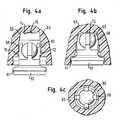
Die in
Das Körbchen 62 besitzt eine Aufnahme 64 mit vier zueinander um 90° versetzt im Kreis angeordneten Armen 68. Die innere Kontur der Arme 68 ist an die Kugeloberfläche der Röntgenkontrast-Kugel angepasst. Auf der Außenseite der Arme 68 ist jeweils ein Vorsprung 70 vorgesehen.The
Die Bohrung 66 weist in einem Ring um ihren kreisförmigen Umfang herum angeordnete Vertiefungen 72 zur Aufnahme der Vorsprünge 70 in der Vorpositionierungsstellung auf. Zudem besitzt die Bohrung ein nach innen vorgewölbtes, geschlossenes Ende 74.The
In der in
Die Vorpositionierungsstellung wird beim Hersteller eingestellt. Danach erfolgt eine Gassterilisation mit Ethylenoxid. Diese erfasst das gesamte Implantat, da alle Oberflächen innerhalb der Bohrung durch das offene Ende der Bohrung und durch die Zwischenräume zwischen den Armen 68 vom Gas umströmt werden. Das Körbchen 62 ist in der Vorpositionierungsstellung kraft- und formschlüssig so fest installiert, dass ein Lösen des Körbchens 62 und der Röntgenkontrast-Kugel 60 vom Element 63 während des Transports ausgeschlossen ist.The pre-positioning position is set by the manufacturer. This is followed by gas sterilization with ethylene oxide. This covers the entire implant, since all surfaces within the bore are flowed around by the open end of the bore and by the spaces between the
Die in
Das Körbchen 62 wird dabei in einem sich verjüngenden Bereich der Bohrung 66 eingeklemmt, während die Kugel 60 zwischen den Armen 68 des Körbchens und dem vorgewölbten Ende 74 der Bohrung kraft- und formschlüssig fixiert ist. Das der Aufnahme 64 entgegengesetzte Ende des Körbchens 62 schließt in der Endpositionierungsstellung mit einer Schnappverbindung 61 bündig mit dem offenen Ende der Bohrung 66 ab.The
Die vierte Ausführungsform, die in
In der Vorpositionierungsstellung wird gewährleistet, dass alle Oberflächen innerhalb der Bohrung unter Berücksichtigung der relativen Beweglichkeit ausreichend vom Sterilisationsgas umströmt werden können. Dabei sind die Kontaktflächen zwischen der Kugel 60 und den Armen 68 kleinflächig. Gleiches gilt für die Kontaktstellen des Körbchens 62 mit dem Implantat 63 in der Schnappverbindung zwischen den Vorsprüngen 70 und den Vertiefungen 72.In the pre-positioning position it is ensured that all surfaces within the bore can be adequately circulated by the sterilization gas, taking into account the relative mobility. The contact surfaces between the
Die in
Die fünfte, in
Die Bohrung 82 besitzt an ihrem offenen Ende einen Bereich 87 mit einem großen Durchmesser. Am geschlossenen Ende der Bohrung 82 ist ein Bereich 89 mit einem kleineren Durchmesser gebildet. Die Bohrung 82 besitzt ferner zwischen dem Bereich 87 und dem Bereich 89 einen sich verjüngenden Bereich 88 und im Bereich 89 einen zum offenen Ende der Bohrung hin angeordneten ringförmigen Haltevorsprung 90.The
Der Röntgenkontrast-Stift 80 weist um den Umfang des Stifts verteilte, in Längsrichtung verlaufende Zähne 92 auf.The
Die Vorpositionierungsstellung wird durch Einbringen des Stifts 80 zwischen den sich verjüngenden Bereich 88 und den Vorsprung 90 der Bohrung beim Hersteller eingestellt. Dabei ist der Röntgenkontrast-Stift 80 axial mit einem Spiel von 0,2 mm gehalten. Die Zähne 92 halten den Stift innerhalb des Bereichs 87 mit dem großen Durchmesser radial zentriert mit einem Spiel von 0,2 mm. Die Berührungsstellen der Spitzen der Zähne 92 mit der Innenwand der Bohrung 82 sind linienförmig. Dadurch werden alle Oberflächen im Inneren der Bohrung 82 wirksam mit Gas sterilisiert.The pre-positioning position is adjusted by inserting the
Die in
Die in
Der Stift 108 besitzt ein konisches Ende 110 und einen ringförmigen Vorsprung 116, der angrenzend an das konische Ende 110 angeordnet ist.The
Das Element 100 enthält eine Bohrung 102 mit einem zum konischen Ende 110 des Stifts komplementären Bereich 106. Die Bohrung 102 weist ferner an ihrem offenen Ende 112 Vorsprünge 114 auf, die in Form von zwei um den Umfang der Bohrung parallel zueinander angeordneten Ringen vorgesehenen sind.The
In der Vorpositionierungsstellung ist der Vorsprung 116 zwischen den zwei Ringen der Vorsprünge 114 axial und radial mit Spiel gehalten. Dabei ist das konische Ende 110 des Stifts ebenfalls mit einem Spiel im Bereich 106 der Bohrung gelagert. Die Kontaktstellen zwischen den Vorsprüngen 114 und dem Stift 108 sind punktförmig, wie aus
Das radiale und axiale Spiel und die punktförmigen Kontaktstellen gewährleisten, dass bei der Sterilisation praktisch alle Oberflächen innerhalb der Bohrung 102 vom Sterilisationsgas umströmt werden.The radial and axial play and the punctiform contact points ensure that during sterilization virtually all surfaces within the
Eine in
Die in
Der Stift 128 besitzt ein konisches Ende 130. Der Stift 128 weist ferner angrenzend an das konische Ende 130 zwei hintereinander angeordnete Vertiefungen 138 und 140 auf, die jeweils ringförmig in den Stift 128 eingebracht sind. Die unmittelbar hinter dem konischen Ende 130 des Stifts angeordnete ringförmige Vertiefung 138 besitzt eine an Vorsprünge 134 am Element 120 angepasste Kontur, während die Vertiefung 140 in Längsrichtung des Stifts 128 im Vergleich zu der Vertiefung 138 größer ausgebildet ist.The
Im Element 120 ist eine Bohrung 122 vorgesehen, die einen zum konischen Ende 130 des Stifts komplementären Bereich 126 aufweist. Die Bohrung 122 weist am offenen Ende 132 die Vorsprünge 134 auf, die in einem Ring um den Umfang der Bohrung herum verteilt sind. Zwischen dem Vorsprung 134 und dem konisch sich verjüngenden Bereich 126 liegt ein Bereich 136 der Bohrung, dessen Querschnitt größer ist als derjenige des Bereichs 126.In
Die Vorpositionierungsstellung wird beim Hersteller vor der Gassterilisation durch Einschieben des Stifts 128 in die Bohrung 122 eingestellt.The Vorpositionierungsstellung is set by the manufacturer before the gas sterilization by inserting the
Das Spiel zwischen den Oberflächen des Stifts 128 und den Innenwänden der Bohrung 122 stellt sicher, dass praktisch alle Oberflächen innerhalb der Bohrung 122 ausreichend vom Sterilisationsgas umströmt werden. In der Vorpositionierungsstellung erfolgt auch der sterile Transport des Implantats.The clearance between the surfaces of the
Nach dem Öffnen der Verpackung und kurz vor dem Einsetzen des Implantats 120 wird der Stift 128 ausgehend von der Vorpositionierungsstellung durch Pressen des Stifts in die Bohrung in der in
Der Stift 154 weist einen konischen Bereich 166 auf, an den sich ein Zapfen 168 anschließt. Der Durchmesser des Zapfens ist kleiner als der Durchmesser des konischen Bereichs 166. Am flachen, vorderen Ende 170 des Zapfens 168 ist um den Umfang herum ein ringförmiger Vorsprung 172 ausgebildet.The
Die Bohrung 152 weist einen zum konischen Bereich 166 des Stiftes 154 komplementären konischen Bereich 156 auf. Zwischen diesem und dem geschlossenen Ende 158 der Bohrung 152 ist ein Bereich 160 mit einem im Vergleich zum konischen Bereich 156 kleineren Durchmesser vorgesehen. Der Bereich 160 weist an seinem Eingang ins Innere der Bohrung spitz zulaufende Vorsprünge 162 und 164 auf, die zwei axial aufeinanderfolgende Ringteile bilden.The
Die in
So wird gewährleistet, dass das Sterilisationsgas auf praktisch alle Oberflächen innerhalb der Bohrung 152 einwirken kann.This ensures that the sterilization gas can act on virtually all surfaces within the
Die in
Die in
Die Schnappfeder 196 der Innenschale besteht aus vier, um 90° versetzt im Kreis angeordneten federnden Stegen 200. An der Außenseite der Stege 200 ist am freien Ende der Stege jeweils ein Vorsprung 202 vorgesehen.The
Die Ausnehmung 198 weist an ihrem offenen Ende um den Umfang der Ausnehmung 198 herum zwei parallel zueinander angeordnete, ringförmige Vorsprünge 206 und 208 auf.The
Die in
Die Endpositionierungsstellung wird durch Verlagern der Innenschale 192 von der Vorpositionierungsstellung in Richtung der Außenschale 190 realisiert, wobei der Vorsprung 202 der Schnappfeder über den Vorsprung 206 gedrückt wird. Wie in
Die zehnte, in
Die Bohrung weist vor dem geschlossenen Ende 218 einen Bereich 217 mit einem kleinen Durchmesser und zwischen diesem und dem offenen Ende einen Bereich 219 mit größerem Durchmesser auf. Zwischen den Bereichen 217 und 219 ist ein sich zum geschlossenen Ende 218 der Bohrung hin verjüngender Bereich 220 vorgesehen. Mit Abstand zu dem sich verjüngenden Bereich 220 ist im Eintrittsbereich 219 der Bohrung ein um die Bohrung umlaufender Vorsprung 222 vorgesehen.The bore has a
Der Stift 210 weist zwei Abschnitte 224 und 226 auf, die mit in Längsrichtung des Stifts verlaufenden Zähnen 228 versehen sind. In den Abschnitten 224 und 226 besitzt der Stift somit einen in
Die in
Die in
Das Verankerungsteil 212 kann als drehfeste Basis für andere Elemente des Implantats verwendet werden. Das Verankerungsteil 212 kann dabei in Bezug auf den Stift 210 rotationssymmetrisch, als Exzenterzapfen oder als gegabelte Aufnahme ausgebildet sein. Die Gabelung der Aufnahme wird bei der Einstellung der Endpositionierung intraoperativ wie benötigt ausgerichtet.The anchoring
- 22
- HüftgelenksprothesenschaleHip joint prosthesis shell
- 44
- Außenschaleouter shell
- 66
- Innenschaleinner shell
- 88th
- AbdeckblechCover plate
- 1010
- Öffnungenopenings
- 1212
- Ausnehmungrecess
- 1414
- Vorsprüngeprojections
- 1616
- Bohrungdrilling
- 1818
- Schnappverbindungsnap
- 2020
- Schrägbodensloping floor
- 2222
- SeitenwandSide wall
- 2424
- Vorsprunghead Start
- 2626
- Rillegroove
- 2828
- Nockecam
- 3030
- Nutgroove
- 3232
- Einschubführunginsertion guide
- 4040
- Röntgenkontrast-KugelX-ray contrast ball
- 4242
- Bohrungdrilling
- 4444
- Elementelement
- 4646
- Vorsprunghead Start
- 4747
- BereichArea
- 4848
- Vorsprunghead Start
- 4949
- BereichArea
- 5050
- geschlossenes Endeclosed end
- 5252
- StopfenPlug
- 6060
- Röntgenkontrast-KugelX-ray contrast ball
- 6161
- Schnappverbindungsnap
- 6262
- Körbchenbasket
- 6363
- Elementelement
- 6464
- Aufnahmeadmission
- 6666
- Bohrungdrilling
- 6666
- Armpoor
- 7070
- Vorsprunghead Start
- 7272
- Vertiefungdeepening
- 7474
- geschlossenes Endeclosed end
- 7676
- Vertiefungdeepening
- 8080
- Röntgenkontrast-StiftX-ray contrast pin
- 8282
- Bohrungdrilling
- 8484
- Elementelement
- 8686
- geschlossenes Endeclosed end
- 8787
- BereichArea
- 8888
- sich verjüngender Bereichrejuvenating area
- 8989
- BereichArea
- 9090
- Vorsprunghead Start
- 9292
- Zahntooth
- 9494
- sich verjüngender Bereichrejuvenating area
- 100100
- Elementelement
- 102102
- Bohrungdrilling
- 104104
- geschlossenes Endeclosed end
- 106106
- BereichArea
- 108108
- Stiftpen
- 110110
- konisches Endeconical end
- 112112
- offenes Endeopen end
- 114114
- Vorsprunghead Start
- 116116
- Vorsprunghead Start
- 120120
- Elementelement
- 122122
- Bohrungdrilling
- 124124
- geschlossenes Endeclosed end
- 126126
- BereichArea
- 128128
- Stiftpen
- 130130
- konisches Endeconical end
- 132132
- offenes Endeopen end
- 134134
- Vorsprunghead Start
- 136136
- BereichArea
- 138138
- Vertiefungdeepening
- 140140
- Vertiefungdeepening
- 150150
- Elementelement
- 152152
- Bohrungdrilling
- 154154
- Metallstiftmetal pin
- 156156
- BereichArea
- 158158
- geschlossenes Endeclosed end
- 160160
- BereichArea
- 162162
- Vorsprunghead Start
- 164164
- Vorsprunghead Start
- 166166
- konischer Bereichconical area
- 168168
- Zapfenspigot
- 170170
- vorderes Endefront end
- 172172
- Vorsprunghead Start
- 190190
- Außenschaleouter shell
- 192192
- Innenschaleinner shell
- 196196
- Schnappfedercatch spring
- 198198
- Ausnehmungrecess
- 200200
- Stegweb
- 202202
- Vorsprunghead Start
- 204204
- Ausnehmungrecess
- 206206
- Vorsprunghead Start
- 208208
- Vorsprunghead Start
- 210210
- Stiftpen
- 212212
- Verankerungsteilanchoring part
- 213213
- Flanschflange
- 214214
- Elementelement
- 216216
- Bohrungdrilling
- 217217
- BereichArea
- 218218
- geschlossenes Endeclosed end
- 219219
- BereichArea
- 220220
- sich verjüngender Bereichrejuvenating area
- 222222
- Vorsprunghead Start
- 224224
- Abschnittsection
- 226226
- Abschnittsection
- 228228
- Zahntooth
- 230230
- Abschnittsection
- 232232
- vorderes Endefront end
Claims (26)
- An implant comprising
at least one first element (8; 40; 60, 62; 80; 108; 128; 154; 192; 210) and a second element (6; 44; 63; 84; 100; 120; 150; 190; 214), wherein the first element is provided in a predefined relative position to the second element,
characterized in that
the first element (8; 40; 60, 62; 80; 108; 128; 154; 192; 210) is mechanically coupled to the second element (6; 44; 63; 84; 100; 120; 150; 190; 214) in a pre-positioning location having play and ensuring a full area gas sterilzation of both elements and can be displaced from this pre-positioning location into an end positioning location corresponding to a fixed assembly of both elements. - An implant in accordance with claim 1,
characterised in that
the first element (8; 40; 60, 62; 80; 108; 128; 154; 192; 210) is provided at least in part in a recess (12; 42; 66; 82; 102; 122; 152; 198; 216) of the second element (6; 44; 63; 84; 100; 120; 150; 190; 214),
wherein the first element (8; 40; 60, 62; 80; 108; 128; 154; 192; 210) is loosely held in the pre-positioning location in the recess (12; 42; 66; 82; 102; 122; 152; 198; 216), wherein the contact points between the first element and the second element in the recess are small in area; and
is connected in a force locked and shape matched manner to the second element (6; 44; 63; 84; 100; 120; 150; 190; 214) in the end positioning location in the recess. - An implant in accordance with claim 1 or claim 2,
characterised in that
the material of at least one of the first and second elements (6, 8; 40, 44; 60, 62, 63; 80, 84; 100, 108; 120, 128; 150, 154; 190, 192; 210, 214) includes highly cross-linked ultra-high molecular weight polyethylene and/or another plastic. - An implant in accordance with any one of the preceding claims,
characterized in that
the material of one of the first and second elements (6, 8; 40, 44; 60, 62, 63; 80, 84; 100, 108; 120, 128; 150, 154; 190, 192; 210, 214) includes a metal, in particular titanium. - An implant in accordance with any one of the preceding claims,
characterized in that
the first element (8; 40; 60, 62; 80; 108; 128; 154; 192; 210) is loosely held in a substantially centred manner in the pre-positioning location. - An implant in accordance with any one of the preceding claims,
characterized in that
the first element (8; 40; 60, 62; 80; 108; 128; 154; 192; 210) is held in the pre-positioning location with a play of at least 0.1 mm. - An implant in accordance with any one of the claims 2 to 6,
characterized in that
the recess has a substantially circular cross-section, the first element (8; 40; 60, 62; 80; 108; 128; 154; 192; 210) has a substantially circular and/or substantially star-shaped cross-section and the first element is radially and axially loosely held in the pre-positioning location in the recess (12; 42; 66; 82; 102; 122; 152; 198; 216). - An implant in accordance with any one of the claims 2 to 7,
characterized in that,
in the pre-positioning location, the contact points between the first element (8; 40; 60, 62; 80; 108; 128; 154; 192; 210) and the second element (6; 44; 63; 84; 100; 120; 150; 190; 214) in the recess (12; 42; 66; 82; 102; 122; 152; 198; 216) are substantially punctiform. - An implant in accordance with any one of the claims 2 to 8,
characterized in that,
in the pre-positioning location, the number of contact points in the recess between the first element (8; 40; 60, 62; 80; 108; 128; 154; 192; 210) and the second element (6; 44; 63; 84; 100; 120; 150; 190; 214) is kept low. - An implant in accordance with any one of the preceding claims,
characterized in that
the first element (40; 60, 62; 80; 108; 128; 154; 192; 210) is loosely held in the pre-positioning location by means of a snap-in connection. - An implant in accordance with any one of the claims 2 to 10,
characterized in that
the recess (82) has at least one projection (90) and a tapering region (88) at the end of the recess; and
the first element (80; 210) is loosely held in the pre-positioning location between the projection (90) and the tapering region (88). - An implant in accordance with any one of the claims 2 to 11,
characterized in that
the recess has at least two projections (46, 48; 114; 162, 164; 206; 208); and
the first element (40; 108; 154) is loosely held in the pre-positioning location between at least two projections. - An implant in accordance with any one of the claims 2 to 12,
characterized in that
the recess (122) has at least one projection (134);
the first element (128) has at least two depressions (138; 140) for receiving the projection (134);
the first element (12) is loosely held in the pre-positioning location by the projection (134) engaging into one of the at least two depressions (138); and
the projection (134) is positioned in the end positioning location in another of the at least two depressions (140). - An implant in accordance with any one of the preceding claims,
characterized in that
the first element (40; 60, 62; 80; 108; 128; 154; 192; 210) is connected in a force locked and shape matched manner in the end positioning location to the second element (6; 44; 63; 84; 100; 120; 150; 190; 214) in a clamping fit and/or by means of a snap-in connection. - An implant in accordance with any one of the preceding claims,
characterized in that
the first element (8; 80; 210) has at least one projection which engages into the second element (6; 84; 214) in the end positioning location. - An implant in accordance with any one of the preceding claims,
characterized in that
the first element (40; 60; 80; 108; 128; 154; 210) is a ball (40; 60) or a pin (80; 108; 128; 154; 210), in particular a metal ball or a metal pin. - An implant in accordance with any one of the claims 2 to 16,
characterized in that
the first element (60, 62) includes a ball (60) and a plug (62) having a receiver for the ball;
the ball (60) is loosely held in the pre-positioning location in the plug (62) or between the plug (62) and the end of the recess; and, in the end positioning location, the plug (62) is held in the recess and the ball (60) is held in the plug (62) in a force locked and shape matched manner. - An implant in accordance with any one of the preceding claims,
characterized in that
the first element is a pin (210) having an anchoring spigot (212). - An implant in accordance with any one of the preceding claims,
characterized in that
the second element is an inner shell (6) of a joint prosthesis and the first element is a cover plate (8) of the inner shell;
a recess (12) is provided in the outer wall of the inner shell with a circular cross-section, a side wall (22) and a base (20) becoming deeper towards the centre of the recess,
wherein the side wall (22) has at least one projection (24) directed to the centre of the recess;
the cover plate (8) is loosely held by the side wall and by the projection in the pre-positioning location;
the cover plate (8) has at least one cam (28) which engages, in the end positioning location, into the side wall (22) of the recess; and the cover plate (8) can be displaced in the recess (12) from the pre-positioning location into the end positioning location by a rotational movement. - An implant in accordance with claim 19,
characterised in that
at least one receiver (30) for the cam (28) is provided in the side wall (22) of the recess in the pre-positioning location. - An implant in accordance with claim 19 or claim 20,
characterised in that
the recess (12) has a groove (26) extending about the recess at the transition from the side wall (22) to the base (20);
and/orin that the side wall (22) of the recess has an insert guide (32) for the insertion of the first element (8) into the pre-positioning location. - An arrangement of an implant in accordance with any one of the preceding claims and of a packaging in which the implant is packed in a gas-sterilized manner,
characterized in that
the elements (6, 8; 40, 44; 60, 62, 63; 80, 84; 100, 108; 120, 128; 150, 154; 190, 192; 210, 214) in the gas-permeable packaging impermeable for microorganisms adopt the pre-positioning position from which they can be moved into the end positioning position after opening the packaging by rotational and/or sliding movements. - A method of providing an arrangement of an implant in accordance with any one of the claims 1 to 21 and of a packaging in which the impalnt is packed in a sterilized manner and with which the implant can be transported and stored:wherein the elements (6, 8; 40, 44; 60, 62, 63; 80, 84; 100, 108; 120, 128; 150, 154; 190, 192; 210, 214) forming the implant are first brought into the pre-positoining location, are then introduced into the packaging in the pre-positoining location and are subsdquently sterilized with gas.
- A method in accordance with claim 23,
characterized in that
the elements (6, 8; 40, 44; 60, 62, 63; 80, 84; 100, 108; 120, 128; 150, 154; 190, 192; 210, 214) forming the implant remain in the pre-positioning location during transport and storage in the packaging. - A method in accordance with claim 23 or claim 24,
characterised in that
the gas sterilzation is carried out with ethylene oxide. - A method in accordance with any one of the claims 23 to 25,
characterised in that
the packaging is closed by a gas-permeable membrane impermeable for microoranisms after the introduction of the elements (6, 8; 40, 44; 60, 62, 63; 80, 84; 100, 108; 120, 128; 150, 154; 190, 192; 210, 214) and before the gas sterilization.
Priority Applications (3)
| Application Number | Priority Date | Filing Date | Title |
|---|---|---|---|
| EP02012124.0AEP1369094B1 (en) | 2002-05-31 | 2002-05-31 | Implant and method of manufacturing a sterile packaged implant |
| US10/410,079US7473279B2 (en) | 2002-05-31 | 2003-04-09 | Implant and a method of manufacturing an implant packed in a sterile manner |
| US12/274,602US8377376B2 (en) | 2002-05-31 | 2008-11-20 | Implant and a method of manufacturing an implant packed in a sterile manner |
Applications Claiming Priority (1)
| Application Number | Priority Date | Filing Date | Title |
|---|---|---|---|
| EP02012124.0AEP1369094B1 (en) | 2002-05-31 | 2002-05-31 | Implant and method of manufacturing a sterile packaged implant |
Publications (2)
| Publication Number | Publication Date |
|---|---|
| EP1369094A1 EP1369094A1 (en) | 2003-12-10 |
| EP1369094B1true EP1369094B1 (en) | 2014-11-26 |
Family
ID=29433089
Family Applications (1)
| Application Number | Title | Priority Date | Filing Date |
|---|---|---|---|
| EP02012124.0AExpired - LifetimeEP1369094B1 (en) | 2002-05-31 | 2002-05-31 | Implant and method of manufacturing a sterile packaged implant |
Country Status (2)
| Country | Link |
|---|---|
| US (2) | US7473279B2 (en) |
| EP (1) | EP1369094B1 (en) |
Families Citing this family (21)
| Publication number | Priority date | Publication date | Assignee | Title |
|---|---|---|---|---|
| US7497874B1 (en) | 2001-02-23 | 2009-03-03 | Biomet Manufacturing Corp. | Knee joint prosthesis |
| US20020120340A1 (en) | 2001-02-23 | 2002-08-29 | Metzger Robert G. | Knee joint prosthesis |
| US8100984B2 (en) | 2003-08-07 | 2012-01-24 | Smith & Nephew, Inc. | Acetabular shell and liner with sterilization channels |
| WO2007047832A2 (en)* | 2005-10-18 | 2007-04-26 | Datalogic Scanning, Inc. | Integrated data reader and bottom-of-basket item detector |
| DE102007031667A1 (en)* | 2006-08-04 | 2008-02-14 | Ceramtec Ag Innovative Ceramic Engineering | Insertion of vibration-damping elements in prosthetic systems for manipulation and damping of natural frequencies |
| JP5448842B2 (en)* | 2007-01-10 | 2014-03-19 | バイオメト マニファクチャリング コーポレイション | Knee joint prosthesis system and implantation method |
| US8328873B2 (en) | 2007-01-10 | 2012-12-11 | Biomet Manufacturing Corp. | Knee joint prosthesis system and method for implantation |
| US8163028B2 (en)* | 2007-01-10 | 2012-04-24 | Biomet Manufacturing Corp. | Knee joint prosthesis system and method for implantation |
| US8562616B2 (en) | 2007-10-10 | 2013-10-22 | Biomet Manufacturing, Llc | Knee joint prosthesis system and method for implantation |
| US8187280B2 (en) | 2007-10-10 | 2012-05-29 | Biomet Manufacturing Corp. | Knee joint prosthesis system and method for implantation |
| GB0718821D0 (en)* | 2007-09-26 | 2007-11-07 | Benoist Girard Sas | Cement spacer for use in prosthetic cup and method of use therein |
| GB0813659D0 (en) | 2008-07-25 | 2008-09-03 | Smith & Nephew | Fracture putty |
| US8123815B2 (en)* | 2008-11-24 | 2012-02-28 | Biomet Manufacturing Corp. | Multiple bearing acetabular prosthesis |
| WO2010129880A2 (en)* | 2009-05-07 | 2010-11-11 | Smith & Nephew, Inc. | Modular trial heads for a prosthetic |
| US8483863B1 (en)* | 2009-05-12 | 2013-07-09 | Glenn Knox | Surgical bone and cartilage shaping on demand with 3D CAD/CAM |
| US8308810B2 (en) | 2009-07-14 | 2012-11-13 | Biomet Manufacturing Corp. | Multiple bearing acetabular prosthesis |
| FR2950525B1 (en)* | 2009-09-28 | 2013-05-10 | Thomas Gradel | HIP PROTHETIC COTYL WITH EXTERNAL FASTENING |
| GB0922339D0 (en) | 2009-12-21 | 2010-02-03 | Mcminn Derek J W | Acetabular cup prothesis and introducer thereof |
| KR101064297B1 (en)* | 2010-01-28 | 2011-09-14 | (주)해양정보기술 | Channy with Underwater Camera |
| FR2961387B1 (en)* | 2010-06-17 | 2013-06-07 | Thomas Gradel | CERAMIC COTYL WITH EXTERNAL FASTENING |
| AU2017204355B2 (en) | 2016-07-08 | 2021-09-09 | Mako Surgical Corp. | Scaffold for alloprosthetic composite implant |
Citations (1)
| Publication number | Priority date | Publication date | Assignee | Title |
|---|---|---|---|---|
| US3932898A (en)* | 1973-09-28 | 1976-01-20 | National Research Development Corporation | Prosthetic heart valve separately formed cage |
Family Cites Families (25)
| Publication number | Priority date | Publication date | Assignee | Title |
|---|---|---|---|---|
| US1489642A (en) | 1921-05-05 | 1924-04-08 | Regan Safety Devices Co Inc | Air-brake-venting speed-controlling mechanism |
| GB1402557A (en)* | 1971-08-09 | 1975-08-13 | Thackray C F Ltd | Femoral prostheses |
| US3863273A (en)* | 1973-09-20 | 1975-02-04 | Meditec Inc | Orthopedic prosthetic implant devices |
| CA1035736A (en)* | 1974-04-25 | 1978-08-01 | Medical Engineering Corporation | Package for prosthetic heart valve or the like |
| US4065816A (en)* | 1975-05-22 | 1978-01-03 | Philip Nicholas Sawyer | Surgical method of using a sterile packaged prosthesis |
| US4705518A (en)* | 1982-04-12 | 1987-11-10 | University Of Utah Research Institute | Artificial sphincter apparatus and method |
| US5019105A (en)* | 1989-08-03 | 1991-05-28 | Biomet, Inc. | Acetabular cup prosthesis assembly |
| US5062853A (en)* | 1989-08-08 | 1991-11-05 | Forte Mark R | Bipolar femoral implant |
| JP2521038Y2 (en)* | 1991-08-13 | 1996-12-25 | 日本特殊陶業株式会社 | Ceramic artificial head |
| US5414049A (en) | 1993-06-01 | 1995-05-09 | Howmedica Inc. | Non-oxidizing polymeric medical implant |
| CN1478812A (en) | 1994-09-21 | 2004-03-03 | Bmg��ʽ���� | Ultra-high molecular weight polyethylene molding for artificial joint and method for producing same |
| FI101933B (en)* | 1995-06-13 | 1998-09-30 | Biocon Oy | Joint prosthesis |
| ES2243980T3 (en) | 1996-02-13 | 2005-12-01 | Massachusetts Institute Of Technology | ULTRA HIGH MOLECULAR POLYETHYLENE PROTECTION DEVICES MOLECULAR TREATED BY FUSION AND RADIATION. |
| US6017975A (en) | 1996-10-02 | 2000-01-25 | Saum; Kenneth Ashley | Process for medical implant of cross-linked ultrahigh molecular weight polyethylene having improved balance of wear properties and oxidation resistance |
| EP1028760B1 (en)* | 1996-10-15 | 2004-04-14 | Orthopaedic Hospital | Wear resistant surface-gradient cross-linked polyethylene |
| US8083745B2 (en)* | 2001-05-25 | 2011-12-27 | Conformis, Inc. | Surgical tools for arthroplasty |
| IT1298376B1 (en)* | 1997-12-16 | 2000-01-05 | Samo Spa | CROSS-LINKING AND STERILIZATION TREATMENT FOR THE PRODUCTION OF POLYETHYLENE PRODUCTS WITH HIGH TRIBOLOGICAL CHARACTERISTICS, |
| FR2782262B1 (en)* | 1998-08-17 | 2001-02-09 | Michel Porte | TEST OR IMPLANTABLE COTYLE WITH ADJUSTABLE ORIENTATION |
| DE59909016D1 (en)* | 1998-10-23 | 2004-05-06 | Ct Pulse Orthopedics Ltd | Artificial socket |
| DE59910410D1 (en)* | 1999-11-03 | 2004-10-07 | Biomet Merck Gmbh Ried | ARTIFICIAL HIP PAN |
| US6379615B1 (en)* | 2000-02-24 | 2002-04-30 | St. Jude Medical, Inc. | Methods of sterilizing articles |
| ATE418933T1 (en)* | 2000-04-27 | 2009-01-15 | Orthopaedic Hospital | OXIDATION-RESISTANT AND ABRASION-RESISTANT POLYETHYLENE FOR HUMAN JOINT REPLACEMENT AND METHOD FOR THE PRODUCTION THEREOF |
| US7025787B2 (en)* | 2001-11-26 | 2006-04-11 | Sdgi Holdings, Inc. | Implantable joint prosthesis and associated instrumentation |
| NL1023717C2 (en) | 2003-06-20 | 2004-12-21 | Fei Co | Preparation carrier for carrying a preparation to be irradiated with an electron beam. |
| WO2008070863A2 (en)* | 2006-12-07 | 2008-06-12 | Interventional Spine, Inc. | Intervertebral implant |
- 2002
- 2002-05-31EPEP02012124.0Apatent/EP1369094B1/ennot_activeExpired - Lifetime
- 2003
- 2003-04-09USUS10/410,079patent/US7473279B2/ennot_activeExpired - Fee Related
- 2008
- 2008-11-20USUS12/274,602patent/US8377376B2/ennot_activeExpired - Fee Related
Patent Citations (1)
| Publication number | Priority date | Publication date | Assignee | Title |
|---|---|---|---|---|
| US3932898A (en)* | 1973-09-28 | 1976-01-20 | National Research Development Corporation | Prosthetic heart valve separately formed cage |
Also Published As
| Publication number | Publication date |
|---|---|
| US20040019380A1 (en) | 2004-01-29 |
| US8377376B2 (en) | 2013-02-19 |
| US7473279B2 (en) | 2009-01-06 |
| US20090081076A1 (en) | 2009-03-26 |
| EP1369094A1 (en) | 2003-12-10 |
Similar Documents
| Publication | Publication Date | Title |
|---|---|---|
| EP1369094B1 (en) | Implant and method of manufacturing a sterile packaged implant | |
| DE68909217T2 (en) | Staggered locking ring system for implantable joint prostheses. | |
| DE69001139T2 (en) | Hip joint socket with two radii. | |
| EP0628294B1 (en) | Partial pelvic endoprothesis | |
| EP1885294B1 (en) | Femoral neck prosthesis | |
| WO2007026003A1 (en) | Implant | |
| WO2004019828A1 (en) | Intervertebral implant comprising a three-part articulation | |
| DE19731442A1 (en) | Cup for a joint endoprosthesis | |
| EP0482320A1 (en) | Acetubular cup for receiving a joint endoprosthesis | |
| EP0920289A1 (en) | Endoprosthesis | |
| DE3903832A1 (en) | Socket part for a joint prosthesis | |
| EP1532950A1 (en) | Spinal disc prosthesis | |
| DE69823968T2 (en) | Method for producing a cold-cured connector for modular parts | |
| WO1995014444A1 (en) | System for constructing a knee-joint endoprosthesis | |
| EP0428127B1 (en) | Endoprothesis to be inplanted with cement | |
| EP1965736A2 (en) | Implant | |
| EP4003238A1 (en) | Combination of graft and replacement piece for filling a bone defect | |
| EP4445874A2 (en) | Hip implant including mouldable fixing tabs | |
| DE9213218U1 (en) | Endoprosthesis shaft | |
| EP2066265B1 (en) | Hip implant | |
| EP1632198A1 (en) | Subcutaneous, intra-muscular coupling for a rigid transcutaneous implant | |
| EP1378215B1 (en) | Subcutaneous, intra-muscular coupling for a rigid transcutaneous implant | |
| WO1990000375A1 (en) | Device for sealing-off medullary canals | |
| DE4408527B4 (en) | Screw-in acetabulum with curved outer contour | |
| DE10308141B4 (en) | Extension sleeve for a modular joint prosthesis |
Legal Events
| Date | Code | Title | Description |
|---|---|---|---|
| PUAI | Public reference made under article 153(3) epc to a published international application that has entered the european phase | Free format text:ORIGINAL CODE: 0009012 | |
| 17P | Request for examination filed | Effective date:20030624 | |
| AK | Designated contracting states | Kind code of ref document:A1 Designated state(s):AT BE CH CY DE DK ES FI FR GB GR IE IT LI LU MC NL PT SE TR | |
| AX | Request for extension of the european patent | Extension state:AL LT LV MK RO SI | |
| AKX | Designation fees paid | Designated state(s):AT CH DE FR GB IT LI | |
| RAP1 | Party data changed (applicant data changed or rights of an application transferred) | Owner name:ZIMMER GMBH | |
| 17Q | First examination report despatched | Effective date:20090917 | |
| APBK | Appeal reference recorded | Free format text:ORIGINAL CODE: EPIDOSNREFNE | |
| APBN | Date of receipt of notice of appeal recorded | Free format text:ORIGINAL CODE: EPIDOSNNOA2E | |
| APBR | Date of receipt of statement of grounds of appeal recorded | Free format text:ORIGINAL CODE: EPIDOSNNOA3E | |
| APAF | Appeal reference modified | Free format text:ORIGINAL CODE: EPIDOSCREFNE | |
| APBT | Appeal procedure closed | Free format text:ORIGINAL CODE: EPIDOSNNOA9E | |
| GRAP | Despatch of communication of intention to grant a patent | Free format text:ORIGINAL CODE: EPIDOSNIGR1 | |
| INTG | Intention to grant announced | Effective date:20140711 | |
| GRAS | Grant fee paid | Free format text:ORIGINAL CODE: EPIDOSNIGR3 | |
| GRAA | (expected) grant | Free format text:ORIGINAL CODE: 0009210 | |
| AK | Designated contracting states | Kind code of ref document:B1 Designated state(s):AT CH DE FR GB IT LI | |
| REG | Reference to a national code | Ref country code:GB Ref legal event code:FG4D Free format text:NOT ENGLISH | |
| REG | Reference to a national code | Ref country code:CH Ref legal event code:NV Representative=s name:DR. GRAF AND PARTNER AG INTELLECTUAL PROPERTY, CH Ref country code:CH Ref legal event code:EP | |
| REG | Reference to a national code | Ref country code:AT Ref legal event code:REF Ref document number:697736 Country of ref document:AT Kind code of ref document:T Effective date:20141215 | |
| REG | Reference to a national code | Ref country code:DE Ref legal event code:R096 Ref document number:50215996 Country of ref document:DE Effective date:20150108 | |
| REG | Reference to a national code | Ref country code:DE Ref legal event code:R097 Ref document number:50215996 Country of ref document:DE | |
| PLBE | No opposition filed within time limit | Free format text:ORIGINAL CODE: 0009261 | |
| STAA | Information on the status of an ep patent application or granted ep patent | Free format text:STATUS: NO OPPOSITION FILED WITHIN TIME LIMIT | |
| 26N | No opposition filed | Effective date:20150827 | |
| REG | Reference to a national code | Ref country code:DE Ref legal event code:R119 Ref document number:50215996 Country of ref document:DE | |
| PG25 | Lapsed in a contracting state [announced via postgrant information from national office to epo] | Ref country code:IT Free format text:LAPSE BECAUSE OF FAILURE TO SUBMIT A TRANSLATION OF THE DESCRIPTION OR TO PAY THE FEE WITHIN THE PRESCRIBED TIME-LIMIT Effective date:20141126 | |
| REG | Reference to a national code | Ref country code:CH Ref legal event code:PL | |
| GBPC | Gb: european patent ceased through non-payment of renewal fee | Effective date:20150531 | |
| PG25 | Lapsed in a contracting state [announced via postgrant information from national office to epo] | Ref country code:CH Free format text:LAPSE BECAUSE OF NON-PAYMENT OF DUE FEES Effective date:20150531 Ref country code:LI Free format text:LAPSE BECAUSE OF NON-PAYMENT OF DUE FEES Effective date:20150531 | |
| REG | Reference to a national code | Ref country code:FR Ref legal event code:ST Effective date:20160129 | |
| PG25 | Lapsed in a contracting state [announced via postgrant information from national office to epo] | Ref country code:DE Free format text:LAPSE BECAUSE OF NON-PAYMENT OF DUE FEES Effective date:20151201 Ref country code:GB Free format text:LAPSE BECAUSE OF NON-PAYMENT OF DUE FEES Effective date:20150531 | |
| PG25 | Lapsed in a contracting state [announced via postgrant information from national office to epo] | Ref country code:FR Free format text:LAPSE BECAUSE OF NON-PAYMENT OF DUE FEES Effective date:20150601 | |
| REG | Reference to a national code | Ref country code:AT Ref legal event code:MM01 Ref document number:697736 Country of ref document:AT Kind code of ref document:T Effective date:20150531 | |
| PG25 | Lapsed in a contracting state [announced via postgrant information from national office to epo] | Ref country code:AT Free format text:LAPSE BECAUSE OF NON-PAYMENT OF DUE FEES Effective date:20150531 |