EP1368685B1 - Cable management panel with sliding drawer - Google Patents
Cable management panel with sliding drawerDownload PDFInfo
- Publication number
- EP1368685B1 EP1368685B1EP01964308AEP01964308AEP1368685B1EP 1368685 B1EP1368685 B1EP 1368685B1EP 01964308 AEP01964308 AEP 01964308AEP 01964308 AEP01964308 AEP 01964308AEP 1368685 B1EP1368685 B1EP 1368685B1
- Authority
- EP
- European Patent Office
- Prior art keywords
- drawer
- chassis
- cable management
- management panel
- radius limiter
- Prior art date
- Legal status (The legal status is an assumption and is not a legal conclusion. Google has not performed a legal analysis and makes no representation as to the accuracy of the status listed.)
- Expired - Lifetime
Links
- 230000007246mechanismEffects0.000claimsdescription40
- 230000014759maintenance of locationEffects0.000claimsdescription18
- 238000003860storageMethods0.000claimsdescription14
- 239000013307optical fiberSubstances0.000claimsdescription12
- 238000005096rolling processMethods0.000claimsdescription3
- 239000000835fiberSubstances0.000description10
- 238000005452bendingMethods0.000description3
- 230000007704transitionEffects0.000description3
- 230000000712assemblyEffects0.000description2
- 238000000429assemblyMethods0.000description2
- 238000009826distributionMethods0.000description2
- 238000004519manufacturing processMethods0.000description2
- 230000037361pathwayEffects0.000description2
- 241001272720Medialuna californiensisSpecies0.000description1
- 230000005540biological transmissionEffects0.000description1
- 238000006073displacement reactionMethods0.000description1
- 230000003287optical effectEffects0.000description1
- 230000002093peripheral effectEffects0.000description1
- 230000000717retained effectEffects0.000description1
- 230000001360synchronised effectEffects0.000description1
Images


Classifications
- G—PHYSICS
- G02—OPTICS
- G02B—OPTICAL ELEMENTS, SYSTEMS OR APPARATUS
- G02B6/00—Light guides; Structural details of arrangements comprising light guides and other optical elements, e.g. couplings
- G02B6/44—Mechanical structures for providing tensile strength and external protection for fibres, e.g. optical transmission cables
- G02B6/4439—Auxiliary devices
- G02B6/444—Systems or boxes with surplus lengths
- G02B6/4453—Cassettes
- G02B6/4455—Cassettes characterised by the way of extraction or insertion of the cassette in the distribution frame, e.g. pivoting, sliding, rotating or gliding
- G—PHYSICS
- G02—OPTICS
- G02B—OPTICAL ELEMENTS, SYSTEMS OR APPARATUS
- G02B6/00—Light guides; Structural details of arrangements comprising light guides and other optical elements, e.g. couplings
- G02B6/44—Mechanical structures for providing tensile strength and external protection for fibres, e.g. optical transmission cables
- G02B6/4439—Auxiliary devices
- G02B6/444—Systems or boxes with surplus lengths
- G02B6/4452—Distribution frames
- G02B6/44526—Panels or rackmounts covering a whole width of the frame or rack
- G—PHYSICS
- G02—OPTICS
- G02B—OPTICAL ELEMENTS, SYSTEMS OR APPARATUS
- G02B6/00—Light guides; Structural details of arrangements comprising light guides and other optical elements, e.g. couplings
- G02B6/44—Mechanical structures for providing tensile strength and external protection for fibres, e.g. optical transmission cables
- G02B6/4439—Auxiliary devices
- G02B6/444—Systems or boxes with surplus lengths
- G02B6/44528—Patch-cords; Connector arrangements in the system or in the box
Definitions
- the present inventionis concerned with management of optical fiber cables.
- the management device of the present inventionhas particular application in the telecommunications industry with respect to storageand/or connection of optical fiber cables with other cables and devices.
- Cable termination, splice and storage devicesare known including, for example, devices shown in U. S. Patent No. 4,792,203 and 5,946,440 , both issued to ADC Telecommunications, Inc. Both of these patents concern devices with moveable trays for storage and management of the optical fiber cables.
- U. S. Patent No. 5,066,149with which claim 1 is delimited, also issued to ADC Telecommunications, Inc., concerns a cable management device including slideable drawers each including a cable slack take-up mechanism.
- optical fiber cablesWhen moving the trays or drawers, unnecessary or excessive displacement of the optical fiber cables is undesirable. As the optical fiber cables are displaced, they are subject to bending and other forces. Bending of the fibers can cause attenuation and loss of signal strength. As a fiber bends, the fiber can also break, resulting in a loss of transmission through the fiber.
- a cable management panelincludes a chassis, and at least one drawer slideably mounted within the chassis.
- the draweris slideable between a first position with the drawer fully inserted within the chassis and a second position with the drawer extended from the interior of the chassis.
- An access locationallows entry and exit of optical fiber cables into a side of the chassis and the drawer.
- the present inventionincludes a fiber take-up mechanism including a radius limiter slideably mounted on the drawer and further slideably mounted relative to the chassis. The radius limiter is moveable from a first position on the drawer toward a second position on the drawer which is forward of the first position as the drawer is moved from the second position to the first position.
- the radius limiterincludes a control mechanism which comprises a rotating member in rolling engagement with the chassis and the drawer, for controlling movement of the radius limiter between the first and second positions as the drawer is moved between the second and first positions.
- the control mechanisminterconnects with each of the chassis at the drawer, and wherein movement of the drawer relative to the chassis causes the radius limiter to move at a reduced speed relative to movement of the drawer.
- the push memberincludes a trough section or retaining optical fiber cables.
- the trough sectionmay include a flared end for further cable protection.
- the push membermay include a cover over a portion of the trough section for further retaining optical fiber cables.
- the push member including the trough sectionincludes a curved shape.
- a further aspect of the push memberpreferably includes an upper retention member for retaining optical fiber cables with the push member during use.
- the retention memberincludes a projecting tab.
- the drawerpreferably receives a drop-in plate including cable storage or cable connection structure for cables entering the panel.
- the drop-in plateslatch to the drawer.
- Panel 10includes a frame or chassis 12 with side brackets 14 for mounting to a rack, cabinet, enclosure, or other mounting fixture.
- Chassis 12includes a font 16, opposed sides 18, and a rear 20. Sides 18 each include cable access openings 22 for cables entering or exiting chassis 12.
- Chassis 12further includes one or more drawers 26 which slide horizontally during use to access the interior of a selected drawer.
- Each drawer 26includes cable management structure, as will be described more fully below.
- Examples of cable management structureinclude devices for storing the cables or connecting the cables to other cables and/or fiber optic devices, such as attenuators, couplers, switches, wave divisions multiplexers (WDMs), splitters/combiners, or splices.
- Drawers 26are slideable relative to chassis 12 via two drawer slides 28 on opposite sides of chassis 12.
- Each drawer 26includes two latches 30 for latching the drawer 26 in the closed position. Each latch 30 engages a side hole 32 in side 18 of chassis 12.
- Each drawer 26further includes a front 32, a rear 34, and a base 36.
- Open sides 37allow for cable entry and exit and prevent cable damage during sliding movement of drawers 26 when accessing the cables and the connectors or other devices in the drawer. Take-up mechanisms are provided, as described below, for managing the cables during sliding movement of drawers 26.
- the cable guides and radius limiters described beloware provided so as to protect the cables and limit bends from going below the minimum bend radius of the cable.
- the cable retention tabs also described belowhelp keep the cables in place once positioned under the tabs by the user.
- Each drawer interioris sized for receiving cable management and/or distribution structure. When the drawer is in the closed position, the cables and management or distribution structures in the interior are protected.
- the structurecan be conveniently mounted on a tray insert which drops into the interior of drawer 26. This allows for convenient structuring of drawer 26 to serve one or more desired functions in module 10.
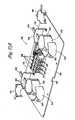
- FIG. 6shows one preferred embodiment of a tray insert or drop-in plate 40 in accordance with the present invention.
- the tray insertscan be customized as the particular needs vary for panel 10.
- each drawer 26can be assembled with the components mounted directly to the drawer bottom.
- the individual drawers 26are constructed as stackable and linkable sub-modules 10a, each with a sub-chassis 12a. Such modularity also allows for ease of use for a variety of different needs for the cable management system.
- Brackets 14link the sub-chassis 12a together.
- FIG. 6also shows one example cable pathway 90 into panel 10.
- base 36 of drawer 26includes side plates 42, a central bottom 44, and an angled transition section 46 on each side of bottom 44 connecting to side plates.
- Base 36further includes a key 48 adjacent to front 32.
- One or more slots 50are positioned in rear 34. Key 48 and slots 50 are usable in mounting tray inserts 40 to drawer 26.
- Fasteners (screws) in holes 49may also be used to secure tray inserts 40 to drawers 26.
- one or more latches 27can be used to releasably mount each tray insert 40 to drawer 26, as shown in FIGS. 55 and 56 .
- Each latch 27is manually moveable to allow release of tray insert 40, by moving latch 27 in the direction of arrow A. To mount tray insert 40 to drawer 26, tray insert 40 automatically moves latch 27 in the direction of arrow A, thereby permitting convenient assembly.
- Side plates 42 of base 36 of drawers 26include longitudinal slots 52. Side plates 42 also mount to one end of each of slides 28 with fasteners through holes 43. Inwardly projecting side ledges 51 of chassis 12 each include longitudinal slots 53 and side notches 54, 56 which cooperate with a take-up mechanism 58 on each side of drawer 26 for managing optical fibers entering and exiting cable management panel 10. Side ledges 51 also mount to the opposite ends of drawer slides 28 with fasteners through holes 55. Side plates 42 are configured as raised surfaces or ledges which are positioned over drawer slides 28 and portions of take-up mechanism 58. Slots 52, 53 vertically overlap when drawer 26 is closed.
- Take-up mechanism 58includes a push member or radius limiter 62, preferably shaped as a half-moon or semi-circle, each with the curved portion 86 facing inwardly, and the planar portion 88 facing outwards.
- Radius limiter 62includes a plurality of tabs 64 for cable retention.
- tabs 64include snaps 66 which are received in slots 68 of radius limiter 62.
- Extending rearwardly and beneath radius limiter 62is an extension 70 which includes a flexible rear tab 72, and a lower tab 73, both for receipt in slot 53.
- Tab 73includes lips 75 to snap mount to slot 53.
- Extension 70also snaps to an underside of radius limiter 62 with snaps 74 which are slideably positioned in slots 52.
- Radius limiter 62is therefore moveably mounted relative to chassis 12 and drawer 26.
- Radius limiter 62acts as a guide for cables passing through access opening 22 on each side of drawer 26.
- Retention structureis provided with take-up mechanism 58 to limit movement of radius limiter 62 to selected times for better control and positioning of the cables.
- projection 72a of tab 72resides in notch 56 to allow drawer 26 to slide rearwardly relative to radius limiter 62, during closing. Slot 52 eventually bottoms out and moves projection 72a out of notch 56, thereby causing radius limiter 62 to move rearwardly with drawer 26.
- Notch 54also retains radius limiter 62 relative to chassis 12 during initial opening of drawer 26.
- Each notch 54, 56includes a ramped surface 54a, 56a allowing release of radius limiter 62 as drawer 26 pulls or pushes on projection 72a during use.
- tray insert 40includes a base 100 including a front notch 102, and rear projections 104.
- Front notch 102receives key 48, and projections 104 are received by slots 50 in drawer 26.
- Side edges 106are positioned adjacent transition sections 46 of base 36 of drawer 26.
- Base 100also includes two upwardly extending rear radius limiters 108.
- Each radius limiter 108includes a main arcuate section 110, a plurality of outwardly extending retention tabs 112, and a lower notch 114 which is positioned over transition section 46 and side plate 42 of base 36 of drawer 26. Cables entering drawer 26 extend from side access opening 22, to take-up mechanism 58 to rear radius limiter 108.
- FIG. 6shows take-up mechanism 58 cooperating with radius limiter 108 for guiding cable 90 into drawer 26.
- Base 100 of example tray insert 40further includes one or more stacks 116 of rotatably mounted or flippable storage trays 118.
- stacks 116are shown for insert 40.
- the trays 118 on the right and left sidesflip in opposite directions as shown in FIG. 9 . By flipping the trays 118, access to the underneath trays in each stack is provided.
- Each tray 118includes a planar base 120, surrounded by an outer peripheral edge 122. Inwardly extending tabs 124 are provided for cable management.
- a center spool 126extends upwardly from base 118, and includes a plurality of cable retention tabs 128. Tray 118 further includes two entry/exit points 130. Cable retention tabs 131 are positioned at each entry/exit point 130. Finger tabs 132 can be grasped by a user's finger to rotate each tray 118 about its rotation axis 133.
- Each tray 118 in stack 116is rotatably mounted to base 100 with a stepped tray mount 140.
- Tray 118includes two projections 142, each having an outwardly projecting pivot post or pin 144 and an outwardly projecting retention tab or bump 146.
- Tray mount 140includes opposed and staggered mounting plates or locations 150 each having holes 154 for receiving pins 144 of trays 118. The staggering, or stair-step, allows for identical trays to be flipped from a horizontal position upwardly so as to allow user access to each tray.
- a detent arrangementis provided for holding the trays in the flipped positions.
- Mounting plates 150each include a notch or groove 156 sized for receiving tab 146 of each projection 142 to maintain each tray in an upward pivoted position when placed there by the user.
- the trays 118stay pivoted upwardly to allow easy and hands-free access to the tray underneath the flipped trays.
- Notches 156 and tabs 146act parallel to the rotation axis of each tray 118.
- trays 118 and tray mount 140are made from plastic.
- Pins 144preferably snap into holes 154 to mount trays 118 to tray mount 140. Cable enters tray 118 at one of points 130, and is wound around spool 126 an appropriate number of times. The cable then exits tray 118 at one of the points 130. In the example shown, one cable 90 is stored per tray 118 (See FIGS. 6 and 8 ).
- Insert 240includes a similar planar base 100 with front notch 102 and rear projections 104.
- Base 100 of tray insert 240also includes rear radius limiters 108.
- Base 100is similar in profile, but may have different structure, for example, holes, for mounting the various cable management devices to tray insert 240.
- Tray insert 240also includes two front stacks 116 of trays 118. Insert 240 differs in that it also includes side radius limiters 242 and retention tabs 243 positioned on opposite sides of base 100 adjacent to stacks 116 of trays 118.
- Base 100further includes adapters 244 for connection to fiber optic connectors.
- Adapters 244are preferably movably mounted to base 100 in sliding adapter arrangement 250.
- Lever arm 252allows a slide assembly 254 to be lifted upwardly to provide easier access to adapters 244.
- Each pair of adapters 244is separately movable with each respective lever 252. Further details of an example of a sliding adapter arrangement like that shown is described in U.S. Patent No. 5,497,444 , the disclosure of which is hereby incorporated by reference. Other adapter arrangements are possible, including arrangements which do not include movable adapters.
- Tray insert 240also includes a wave division multiplexer arrangement with wave division multiplexers (WDMs) 260 connectable to the cables in drawer 26. Cables enter tray insert 240 for connection to adapters 244, and further connection to WDMs 260. Excess cable lengths can be stored in trays 118 and/or wound past limiters 242.
- WDMswave division multiplexers
- a third preferred embodiment of a tray insert 340is shown including rear radius limiting spools 342 with tabs 343 and an optical service channel device (OSC) 344.
- Sliding adapter assemblies like assemblies 250can be provided on base 100 at region 346. Cables enter tray insert 340 for connection to OSC 344, and adapters (if provided). Excess cable is stored in trays 118. Cable passes by spools 342 or limiters 242 to take up the excess and to prevent excessive bending or stress on the fibers.
- FIGS. 16A and Ba fourth preferred embodiment of a tray insert 440 is shown.
- a plurality of sliding adapter arrangements 250are shown on one portion of base 100.
- Attenuators 442are shown on a second portion of base 100.
- Fibersenter and exit tray insert 440 and are connected through adapters 244 and attenuators 442.
- Radius limiters 444, 446 with tabs 448, 450are provided for assisting management of the cables.
- FIGS. 17A and Ba fifth preferred embodiment of a tray insert 550 is shown.
- Sliding adapter arrangements 250are positioned in a central portion of base 100, and a plurality of radius limiters 542 with tabs 543 are positioned to provide variable and selectable pathways for storage of the cables on insert 550.
- Adapters 244can each be provided with a built-in attenuator.
- FIGS. 18A-E and 19A-Dillustrate in combination with FIG. 2 the positioning of take-up mechanism 58 during use to prevent undue stress, pulling or pushing on the cables (optical fibers) entering and exiting module 10 through side access openings 22.
- Radius limiter 62 and tab 72are held in place relative to chassis 12 by rear notch 54 until drawer 26 has moved forward a sufficient amount, such as when a rear end 80 of slot 52 engages the connection between radius limiter 62 and extension 70 (compare FIGS. 18C and 18D ). At that point, radius limiter 62 moves with drawer 26 toward the open position.
- drawer 26 and radius limiter 62stop moving with respect to chassis 12 when lower tab 73 reaches a front end 81 of slot 53 and tab 72 is positioned in front notch 56.
- drawer slides 28can limit the sliding extension of drawer 26. As shown in FIG. 2 , drawer 26 is now in the completely open position.
- front notch 56maintains radius limiter 62 in position relative to chassis 12 while drawer 26 begins rearward movement during closing of drawer 26.
- engagement of a front end 82 of slot 52 with the connection between radius limiter 62 and extension 70causes rearward movement of radius limiter 62 with drawer 26 to the closed position shown in FIG. 18A .
- two take-up mechanisms 58are provided, one for each side access opening 22.
- Radius limiter 62is flipped about a vertical axis when used to assemble the take-up mechanism on the opposite side of drawer 26.
- Tabs 64are placed in the flipped radius limiter 62 to appropriately retain cables positioned around radius limiter 62.
- trays 118can be mounted on either side of drawer 26. Trays 118 are symmetrical about a center axis 145
- the configuration of the interior of drawer 26can vary as the desired functions for panel 10 vary.
- the examples of FIGS. 6-17A and Bare provided to show some of the variations possible.
- FIGS. 20 and 21show a modified panel 510 including a modified take-up mechanism 558.
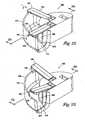
- FIGS. 22-27show further details of the modified take-up mechanism 558.
- Take-up mechanism 558includes a push member or radius limiter 562 which functions in a similar manner as radius limiter 62 noted above.
- Radius limiter 562includes a trough section 570 which cooperates with curved portion 586 of radius limiter 562 and tabs 564 to assist with cable retention during use.
- tabs 564include snaps 566 which snap into slots 568.
- Radius limiter 562mounts in a similar manner to drawer 5 12 and chassis 526 as noted above for take-up mechanism 58 including the push member 62 so as to assist with cable management for cables entering at opening 522 of chassis 526.
- a similar arrangement(not shown) is positioned on the left side of drawer 512.
- Trough section 570includes a base 572 and an outer wall 574. Outer wall 574 is curved in a similar manner as curved portion 586 of radius limiter 562. The curved shape directs cables from the side of module 510, toward a rear of drawer 512. Preferably, trough section 570 includes a trumpeted or flared end 576, along the U-shape to avoid exposing the cables to sharp edges which may cause damage to the cables if tension is applied to the cables and the cables are bent below the minimum bend radius.
- Push member 562is configured for use on the right side of 512. A mirror image of push member 562 can be used on the left side of drawer 512.
- Outer wall 574includes upper notches 578 for ends 565 of tabs 564. Once tabs 564 are snapped with snaps 566 into slots 568, tabs 564 are retained with radius limiter 562. Tabs 564 form a cover over a portion of trough 570 to retain the cables.
- a cable area 580has a generally closed perimeter at tabs 564, base 572 and outer wall 574 to define the cable retention area. While access openings can be provided for continuous cable access, the present embodiment is designed for selective access whereby tabs 564 can be partially lifted upwardly, as shown in FIGS. 21 , 23 , and 25 .
- Tabs 564are moved in -a direction of arrow A for each tab 564 to release a portion of snap 566. Such movement allows for the pivoting upward movement of end 565 of tab 564, thereby allowing easy access for cable positioning within trough 570, or cable removal.
- radius limiter 662is shown in FIG. 28 .
- radius limiter 662includes fixed, opposed tabs 664, 665 which allow cables to be manually placed in cable area 680 by positioning the cables around the openings defined by opposed tabs 664, 665.
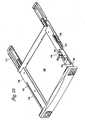
- a drawer 726is slidably mounted to a chassis 712, in a similar manner as drawer 26 and chassis 12, described above.
- a base 736 of drawer 726includes side plates 742, each including a slot 752.
- a take-up mechanism 758includes a radius limiter 762, of the type described above. It is to be appreciated that radius limiter 762 could include the various cable management features of radius limiters 562, 662, described above. Movement of radius limiter 762 is controlled with synchronized movement with drawer 726 with a linear bearing arrangement.
- An extension 770mounts to radius limiter 762 through slot 752.
- Extension 770includes a rearward projection 772 including a rotatable wheel 774, and an upwardly projecting tab 776.
- Wheel 774includes two rotating discs 775 covered by a resilient O-ring 777.
- Chassis 712includes side ledges 751.
- Rear projection 772 of extension 770is positioned between one of side ledges 751 of chassis 712 and one of side plates 742 of drawer 726.
- side plate 742 and side ledge 731are moving in opposite directions relative to one another, with wheel 774 positioned therebetween.
- Radius limiter 762thereby moves relative to chassis 712 at a reduced speed relative to drawer 726. Because wheel 774 is in rolling engagement with both drawer 726 and chassis 712, radius limiter 762 moves at one-half the speed of drawer 726. The speed could be varied if a stepped wheel 774 was provided. In that case, drawer 726 would contact one diameter and chassis 712 would contact another diameter. Moving the limiter 762 at one-half the speed of drawer 726 is useful for cable protection.
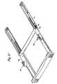
- Side ledges 751each include a rear stop 753 and at least one forward ramp 754.
- Two ramps 754a, bare provided to assist with desired movement of radius limiter 762 when drawer 726 is opened.
- front ramp 754aprevents sliding of wheel 774 until wheel 774 is reengaged by side plate 742.
- Rear ramp 754bis positioned so that should drawer 726 not be fully opened wherein front ramp 754a is not engaged, rear ramp 754b holds wheel 774 until side plate 742 reengages.
- Side ledges 751also include a front stop 756 to limit movement of radius limiter 762.
- Slot 752includes enlarged area 760 for receipt of snaps 780 of extension 770 to snap extension 770 to radius limiter 762. Once snaps 780 are positioned in enlarged areas 760, extension 770 can be slid rearwardly for sliding relative movement relative to drawer 726.
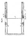
- a modified rear projection 872including two toothed wheels 874a, b.
- Each toothed wheel 874a, bincludes opposed toothed discs 876 mounted for simultaneous rotation on opposite sides of extension member 873.
- the toothed wheels 874a, bare linked with bars 878 to maintain synchronization between toothed wheels 874a, b.
- rear projection 872moves at a reduced speed relative to drawer 826.
- Rear projection 872 and racks 879, 881cause the radius limiter to move at one-half the speed of drawer 826. Different speeds can be achieved by using different sized discs 876 for engaging drawer 826 and chassis 812, respectively.
- the two toothed wheels 874a, bare provided to maintain synchronization when drawer 826 is pulled to the fully opened position wherein drawer 826 is not engaged with rear toothed wheel 874a.
- drawer 926is provided with a front detent 928 which will overcome rear chassis detent 930 as drawer 926 is opened. This retains radius limiter 962 towards the front of drawer 926 as it is opened, keeping tension on the cables. The final rearward position of radius limiter 962 in the direction of arrow B will depend on the amount of slack in the cables.
- a front chassis detent(not visible) can be provided as in panel 10 for limiting the travel of radius limiter 962 forward relative to chassis 912. Further, the front chassis detent allows drawer 926 to move rearwardly before the radius limiter 962 moves rearwardly.
- Each detentincludes a tab 940, 944, on extension 970 and a notch 942, 946.
- radius limiter 1062is slideably mounted to chassis 1012 and drawer 1026.
- a spring 1070applies a bias to radius limiter 1062 to bias it toward a forward position in the direction of arrow D in drawer 1026.
- a cable 1072extends from spring 1070 around tab 1074 to radius limiter 1062.
Landscapes
- Physics & Mathematics (AREA)
- General Physics & Mathematics (AREA)
- Optics & Photonics (AREA)
- Light Guides In General And Applications Therefor (AREA)
- Drawers Of Furniture (AREA)
- Insertion, Bundling And Securing Of Wires For Electric Apparatuses (AREA)
- Handcart (AREA)
Description
- This application is being filed as a PCT International Patent application in the name of ADC Telecommunications, Inc., a U. S. national corporation, designating all countries except US, on 22 August 2001.
- The present invention is concerned with management of optical fiber cables. The management device of the present invention has particular application in the telecommunications industry with respect to storageand/or connection of optical fiber cables with other cables and devices.
- Cable termination, splice and storage devices are known including, for example, devices shown in
U. S. Patent No. 4,792,203 and5,946,440 , both issued to ADC Telecommunications, Inc. Both of these patents concern devices with moveable trays for storage and management of the optical fiber cables.U. S. Patent No. 5,066,149 , with which claim 1 is delimited, also issued to ADC Telecommunications, Inc., concerns a cable management device including slideable drawers each including a cable slack take-up mechanism. - When moving the trays or drawers, unnecessary or excessive displacement of the optical fiber cables is undesirable. As the optical fiber cables are displaced, they are subject to bending and other forces. Bending of the fibers can cause attenuation and loss of signal strength. As a fiber bends, the fiber can also break, resulting in a loss of transmission through the fiber.
- There is a continued need in the art for further cable management devices which address such concerns in the telecommunications industry as ease of use, size, reliability, cost, and protection of the fibers.
- A cable management panel includes a chassis, and at least one drawer slideably mounted within the chassis. The drawer is slideable between a first position with the drawer fully inserted within the chassis and a second position with the drawer extended from the interior of the chassis. An access location allows entry and exit of optical fiber cables into a side of the chassis and the drawer. Further, the present invention includes a fiber take-up mechanism including a radius limiter slideably mounted on the drawer and further slideably mounted relative to the chassis. The radius limiter is moveable from a first position on the drawer toward a second position on the drawer which is forward of the first position as the drawer is moved from the second position to the first position. Also the radius limiter includes a control mechanism which comprises a rotating member in rolling engagement with the chassis and the drawer, for controlling movement of the radius limiter between the first and second positions as the drawer is moved between the second and first positions. The control mechanism interconnects with each of the chassis at the drawer, and wherein movement of the drawer relative to the chassis causes the radius limiter to move at a reduced speed relative to movement of the drawer.
- One aspect of the push member includes a trough section or retaining optical fiber cables. The trough section may include a flared end for further cable protection. The push member may include a cover over a portion of the trough section for further retaining optical fiber cables. Preferably the push member including the trough section includes a curved shape.
- A further aspect of the push member preferably includes an upper retention member for retaining optical fiber cables with the push member during use.
- Preferably the retention member includes a projecting tab.
- The drawer preferably receives a drop-in plate including cable storage or cable connection structure for cables entering the panel. In one embodiment, the drop-in plates latch to the drawer.
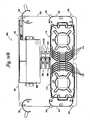
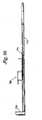
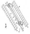
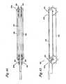
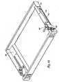
FIG. 1 is a perspective view of a cable management panel or module in accordance with the present invention, shown with one of the drawers in the open position, and shown without the tray insert;FIG.2 is a top view of the cable management panel ofFIG.1 ;FIG. 3 is a side perspective view of the cable management panel ofFIG.1 ;FIG. 3A is a cross-sectional side view through a portion of the chassis showing the retention system of the take-up mechanism;FIG. 3B is a further cross-sectional view of a portion of the take-up mechanism alonglines 3B-3B ofFIG. 3A .FIG.4 is a partially exploded view of the left side of the cable management panel as shown inFIG. 3 ;FIG.5 is a partially exploded perspective view of the right side of the cable management panel ofFIG. 1 ;FIG.6 is a top view of the cable management panel ofFIG. 2 with a first tray insert positioned in the drawer;FIG.7 is a perspective view of the tray insert ofFIG. 6 , with two of the storage trays in flipped positions;FIG. 8 is a top view of the tray insert ofFIG. 7 ;FIG. 9 is a front view of the tray insert ofFIG. 7 ;FIG. 10 is a side view of the tray insert ofFIG. 7 ;FIG. 11 is an enlarged perspective view of one of the stacks of storage trays;FIG. 12 is an exploded view of one of the stacks of storage trays with some of the trays removed for viewing;FIG. 13 is an enlarged exploded view of the storage trays ofFIG. 12 ;FIGS. 14A andB show a second embodiment of a tray insert usable in the cable management panel ofFIG. 1 ;FIGS. 15A andB show a third embodiment of a tray insert usable in the cable management panel ofFIG. 1 ;FIGS. 16A andB show a fourth embodiment of a tray insert usable in the cable management panel ofFIG. 1 ;FIGS. 17A andB show a fifth embodiment of a tray insert usable in the cable management panel ofFIG. 1 ;FIGS. 18A-E show the drawer in various positions during opening from the closed position ofFIG. 18A through the nearly completely open position ofFIG. 18E , the completely open position being shown inFIG. 2 ;FIGS. 19A-D show the drawer in various positions during closing from the completely open position ofFIG. 2 through the nearly completely closed position ofFIG. 19D , just prior to being placed in the fully closed position ofFIG. 18A ;FIG. 20 is a perspective view of an alternative cable management panel including a drawer with a modified take-up mechanism including further cable retention members;FIG. 21 shows the drawer of the cable management panel ofFIG. 20 in the extended position, with the cable retention tabs extended upwardly to permit access to the cables in the trough section;FIG. 22 is a perspective view of the push member of the take-up mechanism ofFIGS. 20 and21 ;FIG. 23 shows the push member ofFIG. 22 with the cable retention tabs lifted upwardly;FIG. 24 is a cross-section along lines 24-24 ofFIG. 22 ;FIG. 25 is a cross-section along lines 25-25 ofFIG. 23 ;FIG. 26 shows the push member ofFIG. 22 without the cable retention tabs;FIG. 27 is a top view of the push member ofFIG. 26 ;FIG. 28 is a perspective view of a further modified take-up mechanism to the take-up mechanism shown inFIGS. 20-27 ;FIGS. 29-31 show perspective, top, and side views of a further alternative cable management panel including a drawer with a modified take-up mechanism including a wheel, with portions of the panel removed for viewing;FIG. 32 is an enlarged portion of the modified take-up mechanism ofFIGS. 29-31 ;FIGS. 33-35 show perspective, top, and side views of the cable management panel ofFIGS. 29-32 , with the drawer partially opened;FIG. 36 is an enlarged portion of the take-up mechanism in the partially opened position ofFIGS. 33-35 ;FIGS. 37-39 show perspective, top, and side views of the cable management panel ofFIGS. 29-32 , with the drawer fully opened;FIGS. 40 and 41 are enlarged perspective and side views of the take-up mechanism of the fully opened drawer ofFIGS. 37-39 ;FIG. 41A shows a perspective view of the extension of the take-up mechanism ofFIGS. 29-41 ;FIGS. 42-44 show exploded perspective, side, and top views of a further modified take-up mechanism including a rack and pinion instead of a wheel as shown inFIGS. 29-41 ;FIGS. 45-53 show various views of a further alternative cable management panel including a drawer with a modified take-up mechanism including chassis and drawer detents for controlling movement of the push member;FIG. 54 shows a top view of a further alternative cable management panel including a drawer with a modified take-up mechanism including a spring biased push member;FIG. 55 shows a latch for latching the drop-in plate within the drawer; andFIG. 56 is a cross-sectional view of the latch ofFIG. 55 .- Referring now to the several drawing figures in which identical elements are numbered identically, a cable management panel or
module 10 according to the present invention is shown.Panel 10 includes a frame orchassis 12 withside brackets 14 for mounting to a rack, cabinet, enclosure, or other mounting fixture.Chassis 12 includes afont 16, opposedsides 18, and a rear 20.Sides 18 each includecable access openings 22 for cables entering or exitingchassis 12.Chassis 12 further includes one ormore drawers 26 which slide horizontally during use to access the interior of a selected drawer. - Each
drawer 26 includes cable management structure, as will be described more fully below. Examples of cable management structure include devices for storing the cables or connecting the cables to other cables and/or fiber optic devices, such as attenuators, couplers, switches, wave divisions multiplexers (WDMs), splitters/combiners, or splices.Drawers 26 are slideable relative tochassis 12 via two drawer slides 28 on opposite sides ofchassis 12. Eachdrawer 26 includes twolatches 30 for latching thedrawer 26 in the closed position. Eachlatch 30 engages aside hole 32 inside 18 ofchassis 12. Eachdrawer 26 further includes a front 32, a rear 34, and abase 36.Open sides 37 allow for cable entry and exit and prevent cable damage during sliding movement ofdrawers 26 when accessing the cables and the connectors or other devices in the drawer. Take-up mechanisms are provided, as described below, for managing the cables during sliding movement ofdrawers 26. The cable guides and radius limiters described below are provided so as to protect the cables and limit bends from going below the minimum bend radius of the cable. The cable retention tabs also described below help keep the cables in place once positioned under the tabs by the user. - Each drawer interior is sized for receiving cable management and/or distribution structure. When the drawer is in the closed position, the cables and management or distribution structures in the interior are protected. In the preferred embodiments, the structure can be conveniently mounted on a tray insert which drops into the interior of
drawer 26. This allows for convenient structuring ofdrawer 26 to serve one or more desired functions inmodule 10.FIG. 6 shows one preferred embodiment of a tray insert or drop-inplate 40 in accordance with the present invention. The tray inserts can be customized as the particular needs vary forpanel 10. Alternatively, eachdrawer 26 can be assembled with the components mounted directly to the drawer bottom. Preferably, theindividual drawers 26 are constructed as stackable andlinkable sub-modules 10a, each with asub-chassis 12a. Such modularity also allows for ease of use for a variety of different needs for the cable management system.Brackets 14 link the sub-chassis 12a together.FIG. 6 also shows oneexample cable pathway 90 intopanel 10. - Referring again to
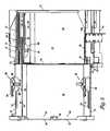
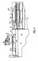
FIGS. 1-5 ,base 36 ofdrawer 26 includesside plates 42, a central bottom 44, and anangled transition section 46 on each side of bottom 44 connecting to side plates.Base 36 further includes a key 48 adjacent tofront 32. One ormore slots 50 are positioned in rear 34.Key 48 andslots 50 are usable in mounting tray inserts 40 todrawer 26. Fasteners (screws) inholes 49 may also be used to secure tray inserts 40 todrawers 26. Alternatively, one ormore latches 27 can be used to releasably mount eachtray insert 40 todrawer 26, as shown inFIGS. 55 and56 . Eachlatch 27 is manually moveable to allow release oftray insert 40, by movinglatch 27 in the direction of arrow A. To mounttray insert 40 todrawer 26,tray insert 40 automatically moveslatch 27 in the direction of arrow A, thereby permitting convenient assembly. Side plates 42 ofbase 36 ofdrawers 26 includelongitudinal slots 52.Side plates 42 also mount to one end of each ofslides 28 with fasteners through holes 43. Inwardly projectingside ledges 51 ofchassis 12 each includelongitudinal slots 53 andside notches mechanism 58 on each side ofdrawer 26 for managing optical fibers entering and exitingcable management panel 10.Side ledges 51 also mount to the opposite ends of drawer slides 28 with fasteners through holes 55.Side plates 42 are configured as raised surfaces or ledges which are positioned over drawer slides 28 and portions of take-upmechanism 58.Slots drawer 26 is closed.- Take-
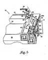
up mechanism 58 includes a push member orradius limiter 62, preferably shaped as a half-moon or semi-circle, each with thecurved portion 86 facing inwardly, and theplanar portion 88 facing outwards.Radius limiter 62 includes a plurality oftabs 64 for cable retention. In one preferred embodiment,tabs 64 includesnaps 66 which are received inslots 68 ofradius limiter 62. Extending rearwardly and beneathradius limiter 62 is anextension 70 which includes a flexiblerear tab 72, and alower tab 73, both for receipt inslot 53.Tab 73 includeslips 75 to snap mount to slot 53.Extension 70 also snaps to an underside ofradius limiter 62 withsnaps 74 which are slideably positioned inslots 52.Radius limiter 62 is therefore moveably mounted relative tochassis 12 anddrawer 26.Radius limiter 62 acts as a guide for cables passing through access opening 22 on each side ofdrawer 26. - Retention structure is provided with take-up
mechanism 58 to limit movement ofradius limiter 62 to selected times for better control and positioning of the cables. As will be described below,projection 72a oftab 72 resides innotch 56 to allowdrawer 26 to slide rearwardly relative toradius limiter 62, during closing.Slot 52 eventually bottoms out and movesprojection 72a out ofnotch 56, thereby causingradius limiter 62 to move rearwardly withdrawer 26.Notch 54 also retainsradius limiter 62 relative tochassis 12 during initial opening ofdrawer 26. Eachnotch surface radius limiter 62 asdrawer 26 pulls or pushes onprojection 72a during use. - Referring now to
FIGS. 6-14 ,tray insert 40 includes a base 100 including afront notch 102, andrear projections 104.Front notch 102 receives key 48, andprojections 104 are received byslots 50 indrawer 26. Side edges 106 are positionedadjacent transition sections 46 ofbase 36 ofdrawer 26.Base 100 also includes two upwardly extending rear radius limiters 108. Eachradius limiter 108 includes a mainarcuate section 110, a plurality of outwardly extendingretention tabs 112, and alower notch 114 which is positioned overtransition section 46 andside plate 42 ofbase 36 ofdrawer 26.Cables entering drawer 26 extend from side access opening 22, to take-upmechanism 58 torear radius limiter 108.FIG. 6 shows take-upmechanism 58 cooperating withradius limiter 108 for guidingcable 90 intodrawer 26. Base 100 ofexample tray insert 40 further includes one ormore stacks 116 of rotatably mounted orflippable storage trays 118. Fourstacks 116 are shown forinsert 40. Thetrays 118 on the right and left sides flip in opposite directions as shown inFIG. 9 . By flipping thetrays 118, access to the underneath trays in each stack is provided.- Each
tray 118 includes aplanar base 120, surrounded by an outerperipheral edge 122. Inwardly extendingtabs 124 are provided for cable management. Acenter spool 126 extends upwardly frombase 118, and includes a plurality ofcable retention tabs 128.Tray 118 further includes two entry/exit points 130.Cable retention tabs 131 are positioned at each entry/exit point 130.Finger tabs 132 can be grasped by a user's finger to rotate eachtray 118 about itsrotation axis 133. Eachtray 118 instack 116 is rotatably mounted tobase 100 with a steppedtray mount 140.Tray 118 includes twoprojections 142, each having an outwardly projecting pivot post or pin 144 and an outwardly projecting retention tab or bump 146.Tray mount 140 includes opposed and staggered mounting plates orlocations 150 each havingholes 154 for receivingpins 144 oftrays 118. The staggering, or stair-step, allows for identical trays to be flipped from a horizontal position upwardly so as to allow user access to each tray. - A detent arrangement is provided for holding the trays in the flipped positions. Mounting
plates 150 each include a notch or groove 156 sized for receivingtab 146 of eachprojection 142 to maintain each tray in an upward pivoted position when placed there by the user. Thetrays 118 stay pivoted upwardly to allow easy and hands-free access to the tray underneath the flipped trays.Notches 156 andtabs 146 act parallel to the rotation axis of eachtray 118. Preferably,trays 118 andtray mount 140 are made from plastic.Pins 144 preferably snap intoholes 154 to mounttrays 118 totray mount 140. Cable enterstray 118 at one ofpoints 130, and is wound aroundspool 126 an appropriate number of times. The cable then exitstray 118 at one of thepoints 130. In the example shown, onecable 90 is stored per tray 118 (SeeFIGS. 6 and8 ). - Referring now to
FIGS. 14A andB , a second preferred embodiment of atray insert 240 is shown including some common parts asinsert 40, and some different parts.Insert 240 includes a similarplanar base 100 withfront notch 102 andrear projections 104.Base 100 oftray insert 240 also includes rear radius limiters 108.Base 100 is similar in profile, but may have different structure, for example, holes, for mounting the various cable management devices totray insert 240.Tray insert 240 also includes twofront stacks 116 oftrays 118.Insert 240 differs in that it also includesside radius limiters 242 andretention tabs 243 positioned on opposite sides ofbase 100 adjacent tostacks 116 oftrays 118.Base 100 further includesadapters 244 for connection to fiber optic connectors.Adapters 244 are preferably movably mounted tobase 100 in slidingadapter arrangement 250.Lever arm 252 allows aslide assembly 254 to be lifted upwardly to provide easier access toadapters 244. Each pair ofadapters 244 is separately movable with eachrespective lever 252. Further details of an example of a sliding adapter arrangement like that shown is described inU.S. Patent No. 5,497,444 , the disclosure of which is hereby incorporated by reference. Other adapter arrangements are possible, including arrangements which do not include movable adapters.Tray insert 240 also includes a wave division multiplexer arrangement with wave division multiplexers (WDMs) 260 connectable to the cables indrawer 26. Cables entertray insert 240 for connection toadapters 244, and further connection toWDMs 260. Excess cable lengths can be stored intrays 118 and/or woundpast limiters 242. - Referring now to
FIGS. 15A andB , a third preferred embodiment of atray insert 340 is shown including rearradius limiting spools 342 withtabs 343 and an optical service channel device (OSC) 344. Sliding adapter assemblies likeassemblies 250 can be provided onbase 100 atregion 346. Cables entertray insert 340 for connection toOSC 344, and adapters (if provided). Excess cable is stored intrays 118. Cable passes byspools 342 orlimiters 242 to take up the excess and to prevent excessive bending or stress on the fibers. - Referring now to
FIGS. 16A andB , a fourth preferred embodiment of atray insert 440 is shown. A plurality of slidingadapter arrangements 250 are shown on one portion ofbase 100.Attenuators 442 are shown on a second portion ofbase 100. Fibers enter andexit tray insert 440 and are connected throughadapters 244 andattenuators 442.Radius limiters tabs - Referring now to
FIGS. 17A andB , a fifth preferred embodiment of atray insert 550 is shown. Slidingadapter arrangements 250 are positioned in a central portion ofbase 100, and a plurality ofradius limiters 542 withtabs 543 are positioned to provide variable and selectable pathways for storage of the cables oninsert 550.Adapters 244 can each be provided with a built-in attenuator. FIGS. 18A-E and19A-D illustrate in combination withFIG. 2 the positioning of take-upmechanism 58 during use to prevent undue stress, pulling or pushing on the cables (optical fibers) entering and exitingmodule 10 throughside access openings 22.Radius limiter 62 andtab 72 are held in place relative tochassis 12 byrear notch 54 untildrawer 26 has moved forward a sufficient amount, such as when arear end 80 ofslot 52 engages the connection betweenradius limiter 62 and extension 70 (compareFIGS. 18C and18D ). At that point,radius limiter 62 moves withdrawer 26 toward the open position.- In the present example,
drawer 26 andradius limiter 62 stop moving with respect tochassis 12 whenlower tab 73 reaches afront end 81 ofslot 53 andtab 72 is positioned infront notch 56. Alternatively, drawer slides 28 can limit the sliding extension ofdrawer 26. As shown inFIG. 2 ,drawer 26 is now in the completely open position. - Referring now to
FIGS. 19A-D ,front notch 56 maintainsradius limiter 62 in position relative tochassis 12 whiledrawer 26 begins rearward movement during closing ofdrawer 26. As shown inFIGS. 19B and4 , engagement of afront end 82 ofslot 52 with the connection betweenradius limiter 62 andextension 70 causes rearward movement ofradius limiter 62 withdrawer 26 to the closed position shown inFIG. 18A . - In the
example module 10, two take-upmechanisms 58 are provided, one for each side access opening 22. For ease of manufacturing, thesame extension 70 andradius limiter 62 are used for each mechanism.Radius limiter 62 is flipped about a vertical axis when used to assemble the take-up mechanism on the opposite side ofdrawer 26.Tabs 64 are placed in the flippedradius limiter 62 to appropriately retain cables positioned aroundradius limiter 62. For a similar reason,trays 118 can be mounted on either side ofdrawer 26.Trays 118 are symmetrical about acenter axis 145 - The configuration of the interior of
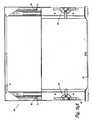
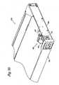
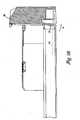
drawer 26 can vary as the desired functions forpanel 10 vary. The examples ofFIGS. 6-17A andB are provided to show some of the variations possible. FIGS. 20 and21 show a modifiedpanel 510 including a modified take-upmechanism 558.FIGS. 22-27 show further details of the modified take-upmechanism 558. Take-up mechanism 558 includes a push member orradius limiter 562 which functions in a similar manner asradius limiter 62 noted above.Radius limiter 562 includes atrough section 570 which cooperates withcurved portion 586 ofradius limiter 562 andtabs 564 to assist with cable retention during use. In a similar manner as formodule 10,tabs 564 includesnaps 566 which snap intoslots 568.Radius limiter 562 mounts in a similar manner to drawer 5 12 andchassis 526 as noted above for take-upmechanism 58 including thepush member 62 so as to assist with cable management for cables entering at opening 522 ofchassis 526. A similar arrangement (not shown) is positioned on the left side ofdrawer 512.Trough section 570 includes abase 572 and anouter wall 574.Outer wall 574 is curved in a similar manner ascurved portion 586 ofradius limiter 562. The curved shape directs cables from the side ofmodule 510, toward a rear ofdrawer 512. Preferably,trough section 570 includes a trumpeted or flaredend 576, along the U-shape to avoid exposing the cables to sharp edges which may cause damage to the cables if tension is applied to the cables and the cables are bent below the minimum bend radius.Push member 562 is configured for use on the right side of 512. A mirror image ofpush member 562 can be used on the left side ofdrawer 512.Outer wall 574 includesupper notches 578 forends 565 oftabs 564. Oncetabs 564 are snapped withsnaps 566 intoslots 568,tabs 564 are retained withradius limiter 562.Tabs 564 form a cover over a portion oftrough 570 to retain the cables. In the example embodiment ofFIGS. 20-27 , acable area 580 has a generally closed perimeter attabs 564,base 572 andouter wall 574 to define the cable retention area. While access openings can be provided for continuous cable access, the present embodiment is designed for selective access wherebytabs 564 can be partially lifted upwardly, as shown inFIGS. 21 ,23 , and25 .Tabs 564 are moved in -a direction of arrow A for eachtab 564 to release a portion ofsnap 566. Such movement allows for the pivoting upward movement ofend 565 oftab 564, thereby allowing easy access for cable positioning withintrough 570, or cable removal.- A modified
radius limiter 662 is shown inFIG. 28 . Instead ofmoveable tabs 564,radius limiter 662 includes fixed, opposedtabs cable area 680 by positioning the cables around the openings defined byopposed tabs - The embodiments above seek to control movement of the radius limiter through the detent and notch mechanisms. Referring now to
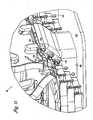
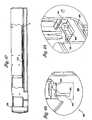
FIGS. 29-41 , adrawer 726 is slidably mounted to achassis 712, in a similar manner asdrawer 26 andchassis 12, described above. Abase 736 ofdrawer 726 includesside plates 742, each including aslot 752. A take-upmechanism 758 includes aradius limiter 762, of the type described above. It is to be appreciated thatradius limiter 762 could include the various cable management features ofradius limiters radius limiter 762 is controlled with synchronized movement withdrawer 726 with a linear bearing arrangement. Anextension 770 mounts toradius limiter 762 throughslot 752.Extension 770 includes arearward projection 772 including arotatable wheel 774, and an upwardly projectingtab 776.Wheel 774 includes tworotating discs 775 covered by a resilient O-ring 777. Chassis 712 includesside ledges 751.Rear projection 772 ofextension 770 is positioned between one ofside ledges 751 ofchassis 712 and one ofside plates 742 ofdrawer 726. During slideable movement ofdrawer 726, relative tochassis 712,side plate 742 and side ledge 731 are moving in opposite directions relative to one another, withwheel 774 positioned therebetween.Radius limiter 762 thereby moves relative tochassis 712 at a reduced speed relative todrawer 726. Becausewheel 774 is in rolling engagement with bothdrawer 726 andchassis 712,radius limiter 762 moves at one-half the speed ofdrawer 726. The speed could be varied if a steppedwheel 774 was provided. In that case,drawer 726 would contact one diameter andchassis 712 would contact another diameter. Moving thelimiter 762 at one-half the speed ofdrawer 726 is useful for cable protection.Side ledges 751 each include arear stop 753 and at least one forward ramp 754. Tworamps 754a, b are provided to assist with desired movement ofradius limiter 762 whendrawer 726 is opened. By referencingFIGS. 37-41 ,front ramp 754a prevents sliding ofwheel 774 untilwheel 774 is reengaged byside plate 742.Rear ramp 754b is positioned so that shoulddrawer 726 not be fully opened whereinfront ramp 754a is not engaged,rear ramp 754b holdswheel 774 untilside plate 742 reengages.Side ledges 751 also include afront stop 756 to limit movement ofradius limiter 762.Slot 752 includesenlarged area 760 for receipt ofsnaps 780 ofextension 770 to snapextension 770 toradius limiter 762. Oncesnaps 780 are positioned inenlarged areas 760,extension 770 can be slid rearwardly for sliding relative movement relative todrawer 726.- Referring now to
FIGS. 42-44 , a modifiedrear projection 872 is shown including twotoothed wheels 874a, b. Eachtoothed wheel 874a, b includes opposedtoothed discs 876 mounted for simultaneous rotation on opposite sides ofextension member 873. Thetoothed wheels 874a, b are linked withbars 878 to maintain synchronization betweentoothed wheels 874a, b. During relative movement ofdrawer 826 andchassis 812,rear projection 872 moves at a reduced speed relative todrawer 826.Rear projection 872 andracks drawer 826. Different speeds can be achieved by using differentsized discs 876 for engagingdrawer 826 andchassis 812, respectively. The twotoothed wheels 874a, b are provided to maintain synchronization whendrawer 826 is pulled to the fully opened position whereindrawer 826 is not engaged with reartoothed wheel 874a. - Referring now to
FIGS. 45-53 ,drawer 926 is provided with afront detent 928 which will overcomerear chassis detent 930 asdrawer 926 is opened. This retainsradius limiter 962 towards the front ofdrawer 926 as it is opened, keeping tension on the cables. The final rearward position ofradius limiter 962 in the direction of arrow B will depend on the amount of slack in the cables. A front chassis detent (not visible) can be provided as inpanel 10 for limiting the travel ofradius limiter 962 forward relative tochassis 912. Further, the front chassis detent allowsdrawer 926 to move rearwardly before theradius limiter 962 moves rearwardly. Each detent includes atab 940, 944, onextension 970 and anotch - Tension in the cables will pull
tab 940 out ofnotch 942 in the direction of arrow C during opening. During closure ofdrawer 926,radius limiter 962 moves with drawer 926 (assuming no front chassis detent), thereby protecting the slack in the cables. - Referring now to
FIG. 54 , a further take-up mechanism 1058 is shown whereradius limiter 1062 is slideably mounted tochassis 1012 anddrawer 1026. Aspring 1070 applies a bias toradius limiter 1062 to bias it toward a forward position in the direction of arrow D indrawer 1026. Acable 1072 extends fromspring 1070 aroundtab 1074 toradius limiter 1062. Whendrawer 1026 is opened,radius limiter 1062 only moves forwardly enough to keep desired tension on the cables undertabs 1064. - The above specification, examples and data provide a complete description of the manufacture and use of the invention. Since many embodiments of the invention can be made, the invention resides in the claims hereinafter appended.
Claims (12)
- A cable management panel (10) comprising:a chassis (12);a drawer (26) slidably mounted within the chassis (12), the drawer (26) slideable between a first position with the drawer (26) fully inserted within the chassis (12) and a second position with the drawer extended from the interior of the chassis (12);an access location (22) allowing entry of optical fiber cable into a side of the chassis (12) and the drawer (26);a cable take-up mechanism (58) including a radius limiter (62) movably mounted on the drawer (26) and movable from a first position on the drawer (26) toward a second position on the drawer (26) which is forward of the first position as the drawer is moved from the second position to the first position, the radius limiter (62) also movably mounted to the chassis (12), andcharacterised by further comprising:a control mechanism which includes a rotating member in rolling engagement with the chassis and the drawer, for moving the radius limiter (62) between the first and second positions as the drawer (62) is moved between the second and first positions;wherein the control mechanism interconnects with each of the chassis (12) and the drawer (62), and wherein movement of the drawer (62) relative to the chassis (12) causes the radius limiter (62) to move at a reduced speed relative to movement of the drawer (62).
- The cable management panel of claim 1, wherein the rotating member includes a wheel.
- The cable management panel of either claims 1 or 2, wherein the rotating member includes a gear, and wherein at least one of the chassis and the drawer includes a rack engaged with the gear.
- The cable management panel of any of claims 1 to 3, wherein the drawer includes a front key and a rear slot, and the cable management panel further comprises a drop-in plate including a notch along a front edge, and a tab along a rear edge, the notch engageable with the key of the drawer, the tab engageable with the slot of the drawer.
- The cable management panel of claim 4, further comprising a latch engageable with the drop-in plate to retain the drop-in plate with the drawer.
- The cable management panel of any of claims 1 to 5, wherein the radius limiter includes a cable trough section.
- The cable management panel of claim 1, wherein the radius limiter includes at least one cable retention tab spaced from the drawer base and a convexly-curved vertical surface adjacent to the tab extending away from the drawer base.
- The cable management panel of claim 7, wherein the tab is a first tab, and wherein the radius limiter includes a second tab extending outwardly from the convexly-curved vertical surface in a direction transverse to a direction of extension of the first tab.
- The cable management panel of either claims 7 or 8, wherein the drawer includes a base and raised side ledges on opposite sides of the drawer, and the cable management panel further includes a drop-in plate including a base and two side edges which are positioned adjacent to the side ledges of the drawer, the plate including two radius limiters, each radius limiter having a portion extending beyond the respective side edges of the base of the plate, each radius limiter having a notch along a lower edge, the notch extending from each respective side edge of the base of the plate to the side ledge of the drawer.
- The cable management panel of any of claims 7 to 9, further comprising a storage tray mount on the drawer, the storage tray mount having a plurality of pairs of opposed, staggered mounting locations, and a plurality of storage trays, each storage tray rotatably mounted to the storage tray mount at one of the staggered mounting locations, wherein one of the trays and the tray mount includes a post and the other includes a hole for receiving the post so as to rotatably mount each tray to the tray mount at each mounting location, and wherein one of the trays and the tray mount includes a projection extending parallel to a rotation axis of the tray, and the other includes a notch wherein the projection is received in the notch when each tray is pivoted vertically upwardly from a first horizontal position to a second pivoted position at an angle to the horizontal.
- The cable management panel of any of claims 7 to 10, wherein the radius limiter is curved on one side and planar on an opposite side, the curved side facing inwardly relative to the drawer, the planar side facing outwardly relative to the drawer, the planar side positioned adjacent to the access location.
- The cable management panel of any of claims 7 to 11, wherein the access location is a first access location, and wherein two take-up mechanisms are provided, one adjacent to each side of the drawer, a second access location provided opposite the side with the first access location.
Priority Applications (1)
| Application Number | Priority Date | Filing Date | Title |
|---|---|---|---|
| EP10175257AEP2251727A1 (en) | 2000-08-28 | 2001-08-22 | Cable Management Panel with Sliding Drawer |
Applications Claiming Priority (3)
| Application Number | Priority Date | Filing Date | Title |
|---|---|---|---|
| US649398 | 1991-02-01 | ||
| US09/649,398US6504988B1 (en) | 2000-01-24 | 2000-08-28 | Cable management panel with sliding drawer |
| PCT/US2001/026185WO2002019005A2 (en) | 2000-08-28 | 2001-08-22 | Cable management panel with sliding drawer |
Publications (2)
| Publication Number | Publication Date |
|---|---|
| EP1368685A2 EP1368685A2 (en) | 2003-12-10 |
| EP1368685B1true EP1368685B1 (en) | 2010-10-06 |
Family
ID=24604603
Family Applications (2)
| Application Number | Title | Priority Date | Filing Date |
|---|---|---|---|
| EP10175257AWithdrawnEP2251727A1 (en) | 2000-08-28 | 2001-08-22 | Cable Management Panel with Sliding Drawer |
| EP01964308AExpired - LifetimeEP1368685B1 (en) | 2000-08-28 | 2001-08-22 | Cable management panel with sliding drawer |
Family Applications Before (1)
| Application Number | Title | Priority Date | Filing Date |
|---|---|---|---|
| EP10175257AWithdrawnEP2251727A1 (en) | 2000-08-28 | 2001-08-22 | Cable Management Panel with Sliding Drawer |
Country Status (10)
| Country | Link |
|---|---|
| US (5) | US6504988B1 (en) |
| EP (2) | EP2251727A1 (en) |
| CN (3) | CN1216307C (en) |
| AR (1) | AR030500A1 (en) |
| AT (1) | ATE483998T1 (en) |
| AU (1) | AU2001285179A1 (en) |
| CA (1) | CA2420819C (en) |
| DE (1) | DE60143223D1 (en) |
| TW (1) | TW512245B (en) |
| WO (1) | WO2002019005A2 (en) |
Families Citing this family (212)
| Publication number | Priority date | Publication date | Assignee | Title |
|---|---|---|---|---|
| US6760531B1 (en) | 1999-03-01 | 2004-07-06 | Adc Telecommunications, Inc. | Optical fiber distribution frame with outside plant enclosure |
| US6438310B1 (en) | 2000-01-24 | 2002-08-20 | Adc Telecommunications, Inc. | Cable management panel with sliding drawer |
| US6504988B1 (en)* | 2000-01-24 | 2003-01-07 | Adc Telecommunications, Inc. | Cable management panel with sliding drawer |
| JP2002082231A (en)* | 2000-09-11 | 2002-03-22 | Auto Network Gijutsu Kenkyusho:Kk | Optical fiber guide device |
| US7079744B2 (en) | 2001-07-06 | 2006-07-18 | Adc Telecommunications, Inc. | Cable management panel with sliding drawer and methods |
| DE20200065U1 (en)* | 2002-01-03 | 2003-03-06 | CCS Technology, Inc., Wilmington, Del. | Splice cassette |
| US6937807B2 (en) | 2002-04-24 | 2005-08-30 | Adc Telecommunications, Inc. | Cable management panel with sliding drawer |
| US6715619B2 (en)* | 2002-07-22 | 2004-04-06 | Adc Telecommunications, Inc. | Fiber management drawer and patch panel |
| US6677520B1 (en) | 2002-07-22 | 2004-01-13 | Adc Telecommunications, Inc. | Fanning tray |
| US6748155B2 (en)* | 2002-07-22 | 2004-06-08 | Adc Telecommunications, Inc. | Fiber management drawer and sliding cable slack limiter |
| DE10239569A1 (en)* | 2002-08-26 | 2004-03-11 | CCS Technology, Inc., Wilmington | Splice cassette |
| JP2006502445A (en)* | 2002-10-11 | 2006-01-19 | スリーエム イノベイティブ プロパティズ カンパニー | Fiber management drawer |
| WO2004034117A2 (en) | 2002-10-11 | 2004-04-22 | 3M Innovative Properties Company | Array of fiber optic splicing cassettes |
| US6804447B2 (en)* | 2002-11-05 | 2004-10-12 | Adc Telecommunications, Inc. | Fiber panel with integrated couplers |
| US6865331B2 (en) | 2003-01-15 | 2005-03-08 | Adc Telecommunications, Inc. | Rotating radius limiter for cable management panel and methods |
| US7142764B2 (en) | 2003-03-20 | 2006-11-28 | Tyco Electronics Corporation | Optical fiber interconnect cabinets, termination modules and fiber connectivity management for the same |
| US6980726B2 (en)* | 2003-05-30 | 2005-12-27 | Lucent Technologies Inc. | Fiber bend limiting device with a dust sealing feature |
| US7171099B2 (en) | 2003-07-31 | 2007-01-30 | Adc Telecommunications, Inc. | Slide arrangement for cable drawer |
| US7369741B2 (en) | 2003-11-17 | 2008-05-06 | Fiber Optics Network Solutions Corp. | Storage adapter with dust cap posts |
| US6983095B2 (en) | 2003-11-17 | 2006-01-03 | Fiber Optic Network Solutions Corporation | Systems and methods for managing optical fibers and components within an enclosure in an optical communications network |
| US7200316B2 (en)* | 2003-11-26 | 2007-04-03 | Corning Cable Systems Llc | Connector housing for a communication network |
| US6944389B2 (en)* | 2003-11-26 | 2005-09-13 | Corning Cable Systems Llc | Connector housing having a sliding tray with a hingeable portion |
| US6944383B1 (en) | 2004-04-12 | 2005-09-13 | Adc Telecommunications, Inc. | Cable management panel with sliding drawer and methods |
| US7200315B2 (en)* | 2004-06-09 | 2007-04-03 | Nortel Networks Limited | Dynamic fiber slack management for telecom racks |
| US7302149B2 (en)* | 2004-09-09 | 2007-11-27 | Adc Telecommunications, Inc. | WDM systems and methods |
| US7277273B2 (en)* | 2004-09-23 | 2007-10-02 | Special Product Company | Equipment cabinet providing full access to equipment housed therein |
| US7171100B2 (en)* | 2004-11-03 | 2007-01-30 | Adc Telecommunications, Inc. | Optical fiber slack storage tray for distribution cabinet |
| US7167628B2 (en) | 2004-12-13 | 2007-01-23 | Adc Telecommunications, Inc. | Service blocker device and method |
| PL1693694T3 (en)* | 2005-02-16 | 2015-03-31 | Corning Res & Dev Corp | Modular cable head for optical networks |
| US7362942B2 (en)* | 2005-03-02 | 2008-04-22 | Adc Telecommunications, Inc. | System and method of grounding fiber storage trays |
| US7349619B2 (en)* | 2005-05-25 | 2008-03-25 | Adc Telecommunications, Inc. | Fiber service blocker |
| US7416349B2 (en)* | 2005-07-27 | 2008-08-26 | Adc Telecommunications, Inc. | Fiber optic adapter module |
| US7397996B2 (en)* | 2005-08-02 | 2008-07-08 | Adc Telecommunications, Inc. | Cable management panel with rear entry |
| US7352945B2 (en)* | 2005-08-29 | 2008-04-01 | Adc Telecommunications, Inc. | Outside plant enclosure with pivoting fiber trays |
| US7330626B2 (en)* | 2005-08-31 | 2008-02-12 | Adc Telecommunications, Inc. | Cabinet including optical bulkhead plate for blown fiber system |
| US7274852B1 (en)* | 2005-12-02 | 2007-09-25 | Adc Telecommunications, Inc. | Splice tray arrangement |
| US7760984B2 (en) | 2006-05-04 | 2010-07-20 | Adc Telecommunications, Inc. | Fiber distribution hub with swing frame and wrap-around doors |
| WO2008065545A2 (en)* | 2006-06-23 | 2008-06-05 | Adc Gmbh | Latch and handle arrangement for a telecommunications panel |
| US7454113B2 (en)* | 2006-07-20 | 2008-11-18 | Adc Telecommunications, Inc. | Grounding device for fiber storage trays |
| US7349615B2 (en)* | 2006-08-25 | 2008-03-25 | Corning Cable Systems Llc | Fiber optic housing assembly for fiber optic connections comprising pivotable portion |
| US7409137B2 (en)* | 2006-10-04 | 2008-08-05 | Adc Telecommunications, Inc. | Slide arrangement for cable drawer |
| US7437049B2 (en)* | 2006-10-10 | 2008-10-14 | Adc Telecommunications, Inc. | Cable management drawer with access panel |
| US7418182B2 (en) | 2006-10-10 | 2008-08-26 | Adc Telecommunications, Inc. | Cable management drawer with access panel |
| US8727458B2 (en)* | 2006-10-20 | 2014-05-20 | Adc Telecommunications, Inc. | High density telecommunications mounting drawer |
| AU2006352360B2 (en)* | 2006-12-27 | 2013-10-17 | Prysmian Cables & Systems Limited | Optical fibre management system |
| US20080169737A1 (en)* | 2007-01-16 | 2008-07-17 | Min-Dy Shen | Adjustable Pull-Out Frame Structure |
| US7570861B2 (en) | 2007-01-19 | 2009-08-04 | Adc Telecommunications, Inc. | Adapter panel with lateral sliding adapter arrays |
| US7570860B2 (en)* | 2007-01-19 | 2009-08-04 | Adc Telecommunications, Inc. | Adapter panel with lateral sliding adapter arrays |
| US7463812B2 (en)* | 2007-01-19 | 2008-12-09 | Adc Telecommunications, Inc. | Overhead cable termination arrangement |
| US7509016B2 (en)* | 2007-03-09 | 2009-03-24 | Adc Telecommunications, Inc. | Telecommunication rack unit tray |
| US7974094B2 (en)* | 2007-03-27 | 2011-07-05 | Commscope, Inc. Of North Carolina | Outside plant telecommunications cabinet direct air cooling system |
| US7715679B2 (en) | 2007-05-07 | 2010-05-11 | Adc Telecommunications, Inc. | Fiber optic enclosure with external cable spool |
| US7567744B2 (en)* | 2007-06-06 | 2009-07-28 | Adc Telecommunications, Inc. | Rear drawer latch |
| US7756379B2 (en) | 2007-08-06 | 2010-07-13 | Adc Telecommunications, Inc. | Fiber optic enclosure with internal cable spool |
| US8798427B2 (en) | 2007-09-05 | 2014-08-05 | Corning Cable Systems Llc | Fiber optic terminal assembly |
| US20090310929A1 (en)* | 2007-10-10 | 2009-12-17 | Adc Telecommunications, Inc. | Optical fiber interconnection apparatus |
| US7751673B2 (en)* | 2007-10-26 | 2010-07-06 | Adc Telecommunications, Inc. | Splice tray holder |
| US8179684B2 (en)* | 2007-10-29 | 2012-05-15 | Adc Telecommunications, Inc. | Sliding adapter panel with living hinge and forward/rearward locking |
| US7751672B2 (en) | 2007-10-31 | 2010-07-06 | Adc Telecommunications, Inc. | Low profile fiber distribution hub |
| US8229265B2 (en) | 2007-11-21 | 2012-07-24 | Adc Telecommunications, Inc. | Fiber distribution hub with multiple configurations |
| US8003890B2 (en) | 2008-01-07 | 2011-08-23 | Chatsworth Products, Inc. | Repositionable shelf-mounted handle spool assembly for cable routing |
| SE535066C2 (en) | 2008-01-07 | 2012-04-03 | Chatsworth Prod Inc | Vertical cable management device |
| US8263867B2 (en) | 2008-01-07 | 2012-09-11 | Chatsworth Products, Inc. | Cable management accessories |
| EP2238492A2 (en) | 2008-01-07 | 2010-10-13 | Chatsworth Products, Inc. | Apparatus and method for organizing cables in a cabinet |
| US7715681B2 (en)* | 2008-03-28 | 2010-05-11 | Adc Telecommunications, Inc. | Rear latch arrangement for sliding drawer |
| US7764859B2 (en)* | 2008-03-28 | 2010-07-27 | Adc Telecommunications, Inc. | Universal cable management panel |
| EP2274645A2 (en)* | 2008-04-11 | 2011-01-19 | ADC Telecommunications, INC. | Fiber management panel |
| US7876993B2 (en) | 2008-05-05 | 2011-01-25 | Adc Telecommunications, Inc. | Drawer arrangement with rack and pinion |
| US8041175B2 (en) | 2008-05-05 | 2011-10-18 | Adc Telecommunications, Inc. | Front-access locking arrangement for sliding drawer |
| ES2560802T3 (en) | 2008-08-27 | 2016-02-22 | Adc Telecommunications, Inc. | Fiber optic adapter with integrally molded bushing alignment structure |
| US8452148B2 (en) | 2008-08-29 | 2013-05-28 | Corning Cable Systems Llc | Independently translatable modules and fiber optic equipment trays in fiber optic equipment |
| US8326107B2 (en)* | 2008-08-29 | 2012-12-04 | Corning Cable Systems Llc | Rear-slidable extension in a fiber optic equipment tray |
| US11294136B2 (en) | 2008-08-29 | 2022-04-05 | Corning Optical Communications LLC | High density and bandwidth fiber optic apparatuses and related equipment and methods |
| US8184938B2 (en)* | 2008-08-29 | 2012-05-22 | Corning Cable Systems Llc | Rear-installable fiber optic modules and equipment |
| US7856166B2 (en) | 2008-09-02 | 2010-12-21 | Corning Cable Systems Llc | High-density patch-panel assemblies for optical fiber telecommunications |
| US7697811B2 (en)* | 2008-09-08 | 2010-04-13 | Ortronics, Inc. | Horizontal fiber optic patching assembly |
| US8526774B2 (en)* | 2008-09-23 | 2013-09-03 | Adc Telecommunications, Inc. | Telecommunications panel and drawer arrangement |
| CN102209921B (en)* | 2008-10-09 | 2015-11-25 | 康宁光缆系统有限公司 | There is the fibre-optic terminus supported from the adapter panel of the input and output optical fiber of optical splitters |
| CN102203653B (en)* | 2008-10-27 | 2015-02-18 | 康宁光缆系统有限责任公司 | Construct variable and modular local convergence points |
| US8879882B2 (en)* | 2008-10-27 | 2014-11-04 | Corning Cable Systems Llc | Variably configurable and modular local convergence point |
| WO2010059623A1 (en) | 2008-11-21 | 2010-05-27 | Adc Telecommunications, Inc. | Fiber optic telecommunications module |
| WO2010088604A1 (en)* | 2009-02-02 | 2010-08-05 | Adc Telecommunications, Inc. | Multi-fiber cable management panel |
| EP2221932B1 (en) | 2009-02-24 | 2011-11-16 | CCS Technology Inc. | Holding device for a cable or an assembly for use with a cable |
| US20100220967A1 (en)* | 2009-02-27 | 2010-09-02 | Cooke Terry L | Hinged Fiber Optic Module Housing and Module |
| US8699838B2 (en) | 2009-05-14 | 2014-04-15 | Ccs Technology, Inc. | Fiber optic furcation module |
| JP5706399B2 (en)* | 2009-05-21 | 2015-04-22 | コーニング ケーブル システムズ リミテッド ライアビリティ カンパニー | Fiber optic equipment supporting movable fiber optic equipment trays and modules, related equipment and methods |
| US9075216B2 (en) | 2009-05-21 | 2015-07-07 | Corning Cable Systems Llc | Fiber optic housings configured to accommodate fiber optic modules/cassettes and fiber optic panels, and related components and methods |
| US8538226B2 (en)* | 2009-05-21 | 2013-09-17 | Corning Cable Systems Llc | Fiber optic equipment guides and rails configured with stopping position(s), and related equipment and methods |
| BRPI1012833A2 (en) | 2009-06-08 | 2018-03-06 | Commscope Inc North Carolina | communication connection system |
| US8712206B2 (en) | 2009-06-19 | 2014-04-29 | Corning Cable Systems Llc | High-density fiber optic modules and module housings and related equipment |
| EP2443497B1 (en) | 2009-06-19 | 2020-03-04 | Corning Cable Systems LLC | High density and bandwidth fiber optic apparatus |
| WO2010148325A1 (en) | 2009-06-19 | 2010-12-23 | Corning Cable Systems Llc | High fiber optic cable packing density apparatus |
| US8467651B2 (en)* | 2009-09-30 | 2013-06-18 | Ccs Technology Inc. | Fiber optic terminals configured to dispose a fiber optic connection panel(s) within an optical fiber perimeter and related methods |
| US8385710B2 (en) | 2009-11-12 | 2013-02-26 | Panduit Corp. | Fiber tray |
| US8625950B2 (en) | 2009-12-18 | 2014-01-07 | Corning Cable Systems Llc | Rotary locking apparatus for fiber optic equipment trays and related methods |
| US8992099B2 (en) | 2010-02-04 | 2015-03-31 | Corning Cable Systems Llc | Optical interface cards, assemblies, and related methods, suited for installation and use in antenna system equipment |
| CN102870021B (en) | 2010-03-02 | 2015-03-11 | 蒂安电子服务有限责任公司 | Fibre-optic telecommunication module |
| US8649649B2 (en) | 2010-03-03 | 2014-02-11 | Adc Telecommunications, Inc. | Fiber distribution hub with connectorized stub cables |
| US9547144B2 (en) | 2010-03-16 | 2017-01-17 | Corning Optical Communications LLC | Fiber optic distribution network for multiple dwelling units |
| US20110235986A1 (en)* | 2010-03-24 | 2011-09-29 | Adc Telecommunications, Inc. | Optical fiber drawer with connectorized stub cable |
| US8913866B2 (en) | 2010-03-26 | 2014-12-16 | Corning Cable Systems Llc | Movable adapter panel |
| CA2796221C (en) | 2010-04-16 | 2018-02-13 | Ccs Technology, Inc. | Sealing and strain relief device for data cables |
| US8792767B2 (en) | 2010-04-16 | 2014-07-29 | Ccs Technology, Inc. | Distribution device |
| EP2381284B1 (en) | 2010-04-23 | 2014-12-31 | CCS Technology Inc. | Under floor fiber optic distribution device |
| US9632270B2 (en) | 2010-04-30 | 2017-04-25 | Corning Optical Communications LLC | Fiber optic housings configured for tool-less assembly, and related components and methods |
| US9075217B2 (en) | 2010-04-30 | 2015-07-07 | Corning Cable Systems Llc | Apparatuses and related components and methods for expanding capacity of fiber optic housings |
| US8879881B2 (en) | 2010-04-30 | 2014-11-04 | Corning Cable Systems Llc | Rotatable routing guide and assembly |
| US8705926B2 (en) | 2010-04-30 | 2014-04-22 | Corning Optical Communications LLC | Fiber optic housings having a removable top, and related components and methods |
| US9720195B2 (en) | 2010-04-30 | 2017-08-01 | Corning Optical Communications LLC | Apparatuses and related components and methods for attachment and release of fiber optic housings to and from an equipment rack |
| US8660397B2 (en) | 2010-04-30 | 2014-02-25 | Corning Cable Systems Llc | Multi-layer module |
| US9519118B2 (en) | 2010-04-30 | 2016-12-13 | Corning Optical Communications LLC | Removable fiber management sections for fiber optic housings, and related components and methods |
| US20110274402A1 (en)* | 2010-05-07 | 2011-11-10 | Giraud William J | Removable fiber management devices for fiber optic housings, and related components and methods |
| WO2011140461A2 (en) | 2010-05-07 | 2011-11-10 | Adc Telecommunications, Inc. | Fiber distribution hub with pass-through interfaces |
| CN110174737A (en) | 2010-06-23 | 2019-08-27 | Adc电信公司 | Telecommunication assembly |
| CN101881870B (en)* | 2010-07-12 | 2011-11-09 | 武汉光迅科技股份有限公司 | Tightening control mechanism for optical cable slide drawer |
| US8718436B2 (en) | 2010-08-30 | 2014-05-06 | Corning Cable Systems Llc | Methods, apparatuses for providing secure fiber optic connections |
| TWI418867B (en)* | 2010-09-30 | 2013-12-11 | Chunghwa Telecom Co Ltd | Thin cable connection device |
| EP2439570B1 (en)* | 2010-10-08 | 2013-04-17 | 3M Innovative Properties Company | Modular support system for optical fiber trays |
| WO2012054454A2 (en) | 2010-10-19 | 2012-04-26 | Corning Cable Systems Llc | Transition box for multiple dwelling unit fiber optic distribution network |
| US9279951B2 (en) | 2010-10-27 | 2016-03-08 | Corning Cable Systems Llc | Fiber optic module for limited space applications having a partially sealed module sub-assembly |
| US9116324B2 (en) | 2010-10-29 | 2015-08-25 | Corning Cable Systems Llc | Stacked fiber optic modules and fiber optic equipment configured to support stacked fiber optic modules |
| US8662760B2 (en) | 2010-10-29 | 2014-03-04 | Corning Cable Systems Llc | Fiber optic connector employing optical fiber guide member |
| US8494332B2 (en) | 2010-11-15 | 2013-07-23 | Adc Telecommunications, Inc. | Tray assembly for a fiber optic enclosure |
| CA2819235C (en) | 2010-11-30 | 2018-01-16 | Corning Cable Systems Llc | Fiber device holder and strain relief device |
| WO2012106510A2 (en) | 2011-02-02 | 2012-08-09 | Corning Cable Systems Llc | Dense fiber optic connector assemblies and related connectors and cables suitable for establishing optical connections for optical backplanes in equipment racks |
| US8556356B2 (en) | 2011-02-21 | 2013-10-15 | Commscope, Inc. Of North Carolina | Communication shelf having supports for pivotable adapter panels and method of mounting adapter panels therein |
| US9008485B2 (en) | 2011-05-09 | 2015-04-14 | Corning Cable Systems Llc | Attachment mechanisms employed to attach a rear housing section to a fiber optic housing, and related assemblies and methods |
| CA2877896C (en) | 2011-06-24 | 2020-07-21 | Adc Telecommunications, Inc. | Fiber termination enclosure with modular plate assemblies |
| AU2012275598A1 (en) | 2011-06-30 | 2014-01-16 | Corning Optical Communications LLC | Fiber optic equipment assemblies employing non-U-width-sized housings and related methods |
| US9081164B2 (en) | 2011-08-24 | 2015-07-14 | Adc Telecommunications, Inc. | Fiber management panel |
| US8953924B2 (en) | 2011-09-02 | 2015-02-10 | Corning Cable Systems Llc | Removable strain relief brackets for securing fiber optic cables and/or optical fibers to fiber optic equipment, and related assemblies and methods |
| US9417418B2 (en) | 2011-09-12 | 2016-08-16 | Commscope Technologies Llc | Flexible lensed optical interconnect device for signal distribution |
| CN103975264B (en) | 2011-10-07 | 2015-09-16 | Adc电信公司 | Slidable fiber optic connection module with cable slack management |
| US9170391B2 (en) | 2011-10-07 | 2015-10-27 | Adc Telecommunications, Inc. | Slidable fiber optic connection module with cable slack management |
| US9002166B2 (en) | 2011-10-07 | 2015-04-07 | Adc Telecommunications, Inc. | Slidable fiber optic connection module with cable slack management |
| RU2611105C2 (en) | 2011-10-07 | 2017-02-21 | Адс Телекоммьюникейшнз, Инк. | Fibre-optic cartridge, system and method |
| US9038832B2 (en) | 2011-11-30 | 2015-05-26 | Corning Cable Systems Llc | Adapter panel support assembly |
| US9219546B2 (en) | 2011-12-12 | 2015-12-22 | Corning Optical Communications LLC | Extremely high frequency (EHF) distributed antenna systems, and related components and methods |
| US9075203B2 (en) | 2012-01-17 | 2015-07-07 | Adc Telecommunications, Inc. | Fiber optic adapter block |
| US10110307B2 (en) | 2012-03-02 | 2018-10-23 | Corning Optical Communications LLC | Optical network units (ONUs) for high bandwidth connectivity, and related components and methods |
| US9285557B2 (en) | 2012-06-27 | 2016-03-15 | Tyco Electronics Raychem Bvba | High density telecommunications chassis with cable management |
| US9521766B2 (en) | 2012-06-27 | 2016-12-13 | CommScope Connectivity Belgium BVBA | High density telecommunications systems with cable management and heat dissipation features |
| US9004778B2 (en) | 2012-06-29 | 2015-04-14 | Corning Cable Systems Llc | Indexable optical fiber connectors and optical fiber connector arrays |
| US9250409B2 (en) | 2012-07-02 | 2016-02-02 | Corning Cable Systems Llc | Fiber-optic-module trays and drawers for fiber-optic equipment |
| US9049500B2 (en) | 2012-08-31 | 2015-06-02 | Corning Cable Systems Llc | Fiber optic terminals, systems, and methods for network service management |
| US9042702B2 (en) | 2012-09-18 | 2015-05-26 | Corning Cable Systems Llc | Platforms and systems for fiber optic cable attachment |
| US9146362B2 (en) | 2012-09-21 | 2015-09-29 | Adc Telecommunications, Inc. | Insertion and removal tool for a fiber optic ferrule alignment sleeve |
| US10082636B2 (en) | 2012-09-21 | 2018-09-25 | Commscope Technologies Llc | Slidable fiber optic connection module with cable slack management |
| US9195021B2 (en) | 2012-09-21 | 2015-11-24 | Adc Telecommunications, Inc. | Slidable fiber optic connection module with cable slack management |
| NZ706687A (en) | 2012-09-28 | 2017-09-29 | Adc Telecommunications Inc | Fiber optic cassette |
| US9146374B2 (en) | 2012-09-28 | 2015-09-29 | Adc Telecommunications, Inc. | Rapid deployment packaging for optical fiber |
| US9223094B2 (en) | 2012-10-05 | 2015-12-29 | Tyco Electronics Nederland Bv | Flexible optical circuit, cassettes, and methods |
| US8909019B2 (en) | 2012-10-11 | 2014-12-09 | Ccs Technology, Inc. | System comprising a plurality of distribution devices and distribution device |
| ES2551077T3 (en) | 2012-10-26 | 2015-11-16 | Ccs Technology, Inc. | Fiber optic management unit and fiber optic distribution device |
| ES1141660Y (en) | 2012-12-19 | 2015-10-14 | Tyco Electronics Raychem Bvba | Distribution device with incrementally added dividers |
| CN105074525A (en) | 2013-01-29 | 2015-11-18 | 泰科电子瑞侃有限公司 | Fiber Distribution System |
| US9128262B2 (en) | 2013-02-05 | 2015-09-08 | Adc Telecommunications, Inc. | Slidable telecommunications tray with cable slack management |
| US9386723B2 (en) | 2013-02-25 | 2016-07-05 | Commscope Technologies Llc | Adjustable swinging bracket |
| US20140247541A1 (en)* | 2013-02-26 | 2014-09-04 | Realm Communications Group, Inc. | Telecom cabinet dual tray slider |
| WO2014133943A1 (en) | 2013-02-27 | 2014-09-04 | Adc Telecommunications, Inc. | Slidable fiber optic connection module with cable slack management |
| US8985862B2 (en) | 2013-02-28 | 2015-03-24 | Corning Cable Systems Llc | High-density multi-fiber adapter housings |
| US9435975B2 (en) | 2013-03-15 | 2016-09-06 | Commscope Technologies Llc | Modular high density telecommunications frame and chassis system |
| ES2719271T3 (en) | 2013-03-19 | 2019-07-09 | Adc Czech Republic Sro | Control of curvature and support of connection cables, mobile, for telecommunications panels |
| EP2989496B1 (en) | 2013-04-24 | 2019-06-12 | CommScope Connectivity Belgium BVBA | Universal mounting mechanism for mounting a telecommunications chassis to a telecommunications fixture |
| AP2015008820A0 (en) | 2013-04-24 | 2015-10-31 | Adc Czech Republic Sro | Optical fiber distribution system |
| EP3014325B1 (en) | 2013-06-28 | 2021-03-24 | CommScope Connectivity Belgium BVBA | Cable management structure for an optical fiber distribution rack |
| CN105705976A (en) | 2013-09-23 | 2016-06-22 | 泰科电子英国有限公司 | Telecommunications chassis |
| ES2768340T3 (en) | 2013-10-18 | 2020-06-22 | CommScope Connectivity Belgium BVBA | Mounting system for telecommunication distribution elements |
| WO2015116672A1 (en) | 2014-01-28 | 2015-08-06 | Adc Telecommunications, Inc. | Slidable fiber optic connection module with cable slack management |
| US9494758B2 (en) | 2014-04-03 | 2016-11-15 | Commscope Technologies Llc | Fiber optic distribution system |
| WO2016012550A2 (en)* | 2014-07-25 | 2016-01-28 | Tyco Electronics Raychem Bvba | Telecommunications distribution elements |
| NZ730425A (en) | 2014-09-16 | 2020-08-28 | CommScope Connectivity Belgium BVBA | Multi-positionable telecommunications tray |
| NZ762104A (en) | 2014-09-16 | 2022-12-23 | CommScope Connectivity Belgium BVBA | Telecommunications tray with a cable routing path extending through a pivot hinge |
| EP4016156B1 (en) | 2014-09-16 | 2024-05-01 | CommScope Connectivity Belgium BVBA | Telecommunications tray assembly |
| KR101718968B1 (en)* | 2014-09-22 | 2017-03-22 | 임채현 | Optical fiber box |
| WO2016094331A1 (en) | 2014-12-10 | 2016-06-16 | Commscope Technologies Llc | Fiber optic cable slack management module |
| US9516781B2 (en)* | 2015-02-19 | 2016-12-06 | All Systems Broadband, Inc. | Fiber optic shelf with a removable roof panel |
| AU2016239875C1 (en) | 2015-04-03 | 2021-06-24 | CommScope Connectivity Belgium BVBA | Telecommunications distribution elements |
| EP3286588B1 (en) | 2015-04-23 | 2020-01-29 | CommScope Connectivity Belgium BVBA | Telecommunications panel assembly with movable adapters |
| US10732372B2 (en)* | 2015-04-24 | 2020-08-04 | Commscope, Inc. Of North Carolina | Shelf for communications rack or cabinet |
| MX2017014377A (en) | 2015-05-15 | 2018-08-15 | Adc Telecommunications Shanghai Distrib Co Ltd | Alignment sleeve assembly and optical fibre adapter. |
| EP3828370B1 (en) | 2015-12-16 | 2022-11-30 | CommScope Connectivity Belgium BVBA | Telecommunications distribution elements |
| US9817201B2 (en) | 2016-04-12 | 2017-11-14 | Ciena Corporation | Sliding assembly and method for fiber management |
| WO2017184501A1 (en) | 2016-04-19 | 2017-10-26 | Commscope, Inc. Of North Carolina | Door assembly for a telecommunications chassis with a combination hinge structure |
| ES2851948T3 (en) | 2016-04-19 | 2021-09-09 | Commscope Inc North Carolina | Telecom rack with slide out trays |
| WO2018226959A1 (en) | 2017-06-07 | 2018-12-13 | Commscope Technologies Llc | Fiber optic adapter and cassette |
| US11409068B2 (en) | 2017-10-02 | 2022-08-09 | Commscope Technologies Llc | Fiber optic circuit and preparation method |
| US11385429B2 (en) | 2017-10-18 | 2022-07-12 | Commscope Technologies Llc | Fiber optic connection cassette |
| US11175469B2 (en) | 2017-10-26 | 2021-11-16 | CommScope Connectivity Belgium BVBA | Telecommunications system |
| US10591692B2 (en)* | 2017-12-27 | 2020-03-17 | Afl Ig Llc | Optical distribution frames |
| US10641980B2 (en) | 2018-02-15 | 2020-05-05 | Panduit Corp. | Rack-mountable fiber optic splice enclosure |
| US11852882B2 (en) | 2018-02-28 | 2023-12-26 | Commscope Technologies Llc | Packaging assembly for telecommunications equipment |
| US10416406B1 (en)* | 2018-03-01 | 2019-09-17 | Afl Telecommunications Llc | Communications module housing |
| WO2019204317A1 (en) | 2018-04-16 | 2019-10-24 | Commscope Technologies Llc | Adapter structure |
| US11635578B2 (en) | 2018-04-17 | 2023-04-25 | CommScope Connectivity Belgium BVBA | Telecommunications distribution elements |
| WO2020014204A1 (en)* | 2018-07-09 | 2020-01-16 | Commscope Technologies Llc | Cable management system for fiber optic trays |
| EP3845044B1 (en) | 2018-08-31 | 2023-02-15 | CommScope Connectivity Belgium BVBA | Frame assemblies for optical fiber distribution elements |
| EP3844546A1 (en) | 2018-08-31 | 2021-07-07 | CommScope Connectivity Belgium BVBA | Frame assemblies for optical fiber distribution elements |
| WO2020043914A1 (en) | 2018-08-31 | 2020-03-05 | CommScope Connectivity Belgium BVBA | Frame assemblies for optical fiber distribution elements |
| PL3844973T3 (en) | 2018-08-31 | 2025-03-03 | CommScope Connectivity Belgium BVBA | Frame assemblies for optical fiber distribution elements |
| EP3844547A1 (en) | 2018-08-31 | 2021-07-07 | CommScope Connectivity Belgium BVBA | Frame assemblies for optical fiber distribution elements |
| WO2020084012A1 (en) | 2018-10-23 | 2020-04-30 | CommScope Connectivity Belgium BVBA | Frame assemblies for optical fiber distribution elements |
| CN111381320B (en)* | 2018-12-29 | 2021-09-21 | 西安华为技术有限公司 | Welding module and communication equipment |
| EP3914947A1 (en) | 2019-01-25 | 2021-12-01 | CommScope Connectivity Belgium BVBA | Frame assemblies for optical fiber distribution elements |
| CN110456472A (en)* | 2019-09-04 | 2019-11-15 | 合肥昌嵩精密制造有限公司 | A kind of sub- frame of fibre distribution frame unit |
| US11109506B2 (en) | 2019-11-14 | 2021-08-31 | Ciena Corporation | Fiber management sliding tray system |
| WO2021148544A1 (en) | 2020-01-22 | 2021-07-29 | CommScope Connectivity Belgium BVBA | Cable termination units for optical fiber distribution elements |
| US12099246B2 (en) | 2020-01-24 | 2024-09-24 | CommScope Connectivity Belgium BVBA | Telecommunications distribution elements |
| US12339511B2 (en) | 2020-03-31 | 2025-06-24 | Commscope Technologies Llc | Fiber optic cable management systems and methods |
| US11947178B2 (en) | 2020-09-17 | 2024-04-02 | Panduit Corp. | Optical distribution and splice frame including cassettes |
| CN112433514A (en)* | 2020-11-13 | 2021-03-02 | 苏州鲍斯智能制造技术有限公司 | Intelligent controllable drawer assembly and material storing and taking cabinet |
| US20240114267A1 (en)* | 2022-09-29 | 2024-04-04 | viaPhoton, Inc. | Miniature network interface device |
Family Cites Families (46)
| Publication number | Priority date | Publication date | Assignee | Title |
|---|---|---|---|---|
| US2864656A (en)* | 1954-06-25 | 1958-12-16 | Yorinks Alexander | Slide mechanism |
| US3438310A (en)* | 1965-08-27 | 1969-04-15 | Gen Foods Corp | Envelope-forming apparatus and method |
| US4373776A (en) | 1980-06-30 | 1983-02-15 | Northern Telecom Limited | Protection case for optical fiber splices |
| US4792203A (en) | 1985-09-17 | 1988-12-20 | Adc Telecommunications, Inc. | Optical fiber distribution apparatus |
| US4840449A (en) | 1988-01-27 | 1989-06-20 | American Telephone And Telegraph Company, At&T Bell Laboratories | Optical fiber splice organizer |
| US4820007A (en) | 1988-02-12 | 1989-04-11 | American Telephone And Telegraph Company At&T Bell Laboratories | Cable closure and methods of assembling |
| US4898448A (en)* | 1988-05-02 | 1990-02-06 | Gte Products Corporation | Fiber distribution panel |
| US4900123A (en)* | 1988-08-29 | 1990-02-13 | Gte Products Corporation | 1550 nm fiber distribution panel |
| DE3838428A1 (en)* | 1988-11-12 | 1990-05-31 | Philips Patentverwaltung | SWITCH DISTRIBUTOR FOR THE PRODUCTION OF FREELY SELECTABLE OPTICAL CONNECTORS |
| US5071211A (en)* | 1988-12-20 | 1991-12-10 | Northern Telecom Limited | Connector holders and distribution frame and connector holder assemblies for optical cable |
| US5316243A (en)* | 1989-07-31 | 1994-05-31 | Adc Telecommunications, Inc. | Optic cable management |
| US4995688A (en) | 1989-07-31 | 1991-02-26 | Adc Telecommunications, Inc. | Optical fiber distribution frame |
| US5142606A (en)* | 1990-01-22 | 1992-08-25 | Porta Systems Corp. | Optical fiber cable distribution frame and support |
| US5142607A (en)* | 1990-03-20 | 1992-08-25 | Rittal-Werk Rudolf Loh Gmbh & Co. Kg | Splice box for optical wave guide |
| FR2663917B1 (en)* | 1990-06-29 | 1993-06-04 | Cit Alcatel | MODULAR DEVICE FOR STORING RESERVES OF TRANSMISSION SUPPORT ON LINKS, PARTICULARLY FIBER OPTIC. |
| US5066149A (en) | 1990-09-11 | 1991-11-19 | Adc Telecommunications, Inc. | Splice tray with slack take-up |
| US5127082A (en)* | 1991-03-22 | 1992-06-30 | The Siemon Company | Fiber optic patch panel |
| FR2678076B1 (en)* | 1991-06-20 | 1994-09-23 | Cit Alcatel | MODULE FOR STORING A TRANSMISSION SUPPORT RESERVE ON A LINK, PARTICULARLY WITH OPTICAL FIBER AND STORAGE DEVICE COMPRISING A SET OF SUCH MODULES. |
| US5167001A (en)* | 1991-09-03 | 1992-11-24 | Northern Telecom Limited | Optical fiber storage and connector tray and shelf and tray assembly |
| US5247603A (en) | 1992-01-24 | 1993-09-21 | Minnesota Mining And Manufacturing Company | Fiber optic connection system with exchangeable cross-connect and interconnect cards |
| FR2687800B1 (en)* | 1992-02-21 | 1994-04-08 | Mars Actel | ADAPTABLE CASSETTE FOR LOVING AND SPLICING OPTICAL FIBERS. |
| FR2687744B1 (en)* | 1992-02-21 | 1994-04-08 | Mars Actel | SET OF ARTICULATED FLAT MODULES. |
| US5240209A (en) | 1992-11-17 | 1993-08-31 | Telect, Inc. | Telecommunication multiple cable carrier |
| US5323480A (en) | 1992-11-25 | 1994-06-21 | Raychem Corporation | Fiber optic splice closure |
| US5339379A (en) | 1993-06-18 | 1994-08-16 | Telect, Inc. | Telecommunication fiber optic cable distribution apparatus |
| GB9318633D0 (en) | 1993-09-08 | 1993-10-27 | Raychem Sa Nv | Organization of optical fibres |
| TW232757B (en) | 1994-01-21 | 1994-10-21 | Adc Telecommunications Inc | High-density fiber distribution frame |
| US5402515A (en)* | 1994-03-01 | 1995-03-28 | Minnesota Mining And Manufacturing Company | Fiber distribution frame system, cabinets, trays and fiber optic connector couplings |
| US5511144A (en)* | 1994-06-13 | 1996-04-23 | Siecor Corporation | Optical distribution frame |
| US5519804A (en)* | 1994-06-22 | 1996-05-21 | At&T Corp. | Universal splice tray |
| GB2292466B (en)* | 1994-08-15 | 1997-09-10 | Pirelli General Plc | Guiding optical fibres in ducts |
| WO1996010203A1 (en) | 1994-09-28 | 1996-04-04 | Telephone Cables Limited | A splice tray |
| DE29504191U1 (en)* | 1995-03-01 | 1996-03-28 | Krone Ag, 14167 Berlin | Insert for receiving devices of the LWL technology |
| US5724469A (en)* | 1996-01-26 | 1998-03-03 | Ortronics, Inc. | Adjustable fiber storage plate |
| US5836148A (en)* | 1996-02-06 | 1998-11-17 | Kunimorikagaku Ltd. | Cable chain |
| US5811055A (en)* | 1996-02-06 | 1998-09-22 | Geiger; Michael B. | Torch mounted gas scavaging system for manual and robotic welding and cutting torches |
| DE19611770C2 (en) | 1996-03-14 | 1998-04-09 | Krone Ag | Manageable splice cassette |
| DE69713544T2 (en)* | 1996-04-12 | 2003-02-20 | Telephone Cables Ltd., Dagenham | Arrangement of an optical fiber |
| US5802237A (en) | 1997-04-18 | 1998-09-01 | Minnesota Mining And Manufacturing Company | Optical fiber organizer |
| US5862290A (en)* | 1997-05-01 | 1999-01-19 | Lucent Technologies Inc. | Optical fiber cable splice closure |
| US6009224A (en)* | 1997-11-06 | 1999-12-28 | Allen; Barry Wayne | Fiber optic organizer with lockable trays and method of accessing a tray |
| US5946440A (en) | 1997-11-17 | 1999-08-31 | Adc Telecommunications, Inc. | Optical fiber cable management device |
| US6215938B1 (en)* | 1998-09-21 | 2001-04-10 | Adc Telecommunications, Inc. | Fiber optic cabinet and tray |
| US6226436B1 (en) | 1999-11-18 | 2001-05-01 | Lucent Technologies, Inc. | Fiber optical pedestal |
| US6504988B1 (en) | 2000-01-24 | 2003-01-07 | Adc Telecommunications, Inc. | Cable management panel with sliding drawer |
| US6438310B1 (en)* | 2000-01-24 | 2002-08-20 | Adc Telecommunications, Inc. | Cable management panel with sliding drawer |
- 2000
- 2000-08-28USUS09/649,398patent/US6504988B1/ennot_activeExpired - Lifetime
- 2001
- 2001-08-22DEDE60143223Tpatent/DE60143223D1/ennot_activeExpired - Lifetime
- 2001-08-22AUAU2001285179Apatent/AU2001285179A1/ennot_activeAbandoned
- 2001-08-22CNCN018171664Apatent/CN1216307C/ennot_activeExpired - Lifetime
- 2001-08-22ATAT01964308Tpatent/ATE483998T1/ennot_activeIP Right Cessation
- 2001-08-22CACA2420819Apatent/CA2420819C/ennot_activeExpired - Lifetime
- 2001-08-22CNCNB2005100094847Apatent/CN100392462C/ennot_activeExpired - Lifetime
- 2001-08-22EPEP10175257Apatent/EP2251727A1/ennot_activeWithdrawn
- 2001-08-22CNCNB200510009489XApatent/CN100392463C/ennot_activeExpired - Fee Related
- 2001-08-22EPEP01964308Apatent/EP1368685B1/ennot_activeExpired - Lifetime
- 2001-08-22WOPCT/US2001/026185patent/WO2002019005A2/enactiveApplication Filing
- 2001-08-27TWTW090121047Apatent/TW512245B/ennot_activeIP Right Cessation
- 2001-08-28ARARP010104089Apatent/AR030500A1/ennot_activeApplication Discontinuation
- 2002
- 2002-11-26USUS10/306,816patent/US6968111B2/ennot_activeExpired - Lifetime
- 2004
- 2004-07-20USUS10/894,898patent/US7120348B2/ennot_activeExpired - Lifetime
- 2006
- 2006-07-25USUS11/492,304patent/US7302154B2/ennot_activeExpired - Fee Related
- 2007
- 2007-08-10USUS11/891,638patent/US7463811B2/ennot_activeExpired - Fee Related
Also Published As
| Publication number | Publication date |
|---|---|
| EP2251727A1 (en) | 2010-11-17 |
| US6968111B2 (en) | 2005-11-22 |
| CN100392462C (en) | 2008-06-04 |
| US7302154B2 (en) | 2007-11-27 |
| US20080063350A1 (en) | 2008-03-13 |
| CN1651957A (en) | 2005-08-10 |
| WO2002019005A2 (en) | 2002-03-07 |
| US20070058918A1 (en) | 2007-03-15 |
| AR030500A1 (en) | 2003-08-20 |
| ATE483998T1 (en) | 2010-10-15 |
| US6504988B1 (en) | 2003-01-07 |
| HK1061437A1 (en) | 2004-09-17 |
| US20030165315A1 (en) | 2003-09-04 |
| CN1651956A (en) | 2005-08-10 |
| TW512245B (en) | 2002-12-01 |
| WO2002019005A3 (en) | 2003-07-10 |
| AU2001285179A1 (en) | 2002-03-13 |
| US20040258384A1 (en) | 2004-12-23 |
| CN1216307C (en) | 2005-08-24 |
| DE60143223D1 (en) | 2010-11-18 |
| US7463811B2 (en) | 2008-12-09 |
| CA2420819A1 (en) | 2002-03-07 |
| EP1368685A2 (en) | 2003-12-10 |
| CN100392463C (en) | 2008-06-04 |
| US7120348B2 (en) | 2006-10-10 |
| CN1470004A (en) | 2004-01-21 |
| CA2420819C (en) | 2012-01-24 |
Similar Documents
| Publication | Publication Date | Title |
|---|---|---|
| EP1368685B1 (en) | Cable management panel with sliding drawer | |
| US10459182B2 (en) | Cable management panel with sliding drawer | |
| US11320619B2 (en) | Cable management panel with sliding drawer and methods | |
| CA2492828C (en) | Fiber management drawer and patch panel | |
| US6677520B1 (en) | Fanning tray | |
| US6937807B2 (en) | Cable management panel with sliding drawer | |
| US6944383B1 (en) | Cable management panel with sliding drawer and methods | |
| US6748155B2 (en) | Fiber management drawer and sliding cable slack limiter | |
| HK1061437B (en) | Cable management panel with sliding drawer | |
| HK1150665A (en) | Cable management panel with sliding drawer |
Legal Events
| Date | Code | Title | Description |
|---|---|---|---|
| PUAI | Public reference made under article 153(3) epc to a published international application that has entered the european phase | Free format text:ORIGINAL CODE: 0009012 | |
| 17P | Request for examination filed | Effective date:20030314 | |
| AK | Designated contracting states | Kind code of ref document:A2 Designated state(s):AT BE CH CY DE DK ES FI FR GB GR IE IT LI LU MC NL PT SE TR | |
| AX | Request for extension of the european patent | Extension state:AL LT LV MK RO SI | |
| REG | Reference to a national code | Ref country code:HK Ref legal event code:DE Ref document number:1061437 Country of ref document:HK | |
| 17Q | First examination report despatched | Effective date:20070130 | |
| GRAP | Despatch of communication of intention to grant a patent | Free format text:ORIGINAL CODE: EPIDOSNIGR1 | |
| GRAS | Grant fee paid | Free format text:ORIGINAL CODE: EPIDOSNIGR3 | |
| GRAA | (expected) grant | Free format text:ORIGINAL CODE: 0009210 | |
| AK | Designated contracting states | Kind code of ref document:B1 Designated state(s):AT BE CH CY DE DK ES FI FR GB GR IE IT LI LU MC NL PT SE TR | |
| REG | Reference to a national code | Ref country code:GB Ref legal event code:FG4D | |
| REG | Reference to a national code | Ref country code:CH Ref legal event code:EP | |
| REG | Reference to a national code | Ref country code:IE Ref legal event code:FG4D | |
| REF | Corresponds to: | Ref document number:60143223 Country of ref document:DE Date of ref document:20101118 Kind code of ref document:P | |
| REG | Reference to a national code | Ref country code:NL Ref legal event code:VDEP Effective date:20101006 | |
| PG25 | Lapsed in a contracting state [announced via postgrant information from national office to epo] | Ref country code:SE Free format text:LAPSE BECAUSE OF FAILURE TO SUBMIT A TRANSLATION OF THE DESCRIPTION OR TO PAY THE FEE WITHIN THE PRESCRIBED TIME-LIMIT Effective date:20101006 Ref country code:FI Free format text:LAPSE BECAUSE OF FAILURE TO SUBMIT A TRANSLATION OF THE DESCRIPTION OR TO PAY THE FEE WITHIN THE PRESCRIBED TIME-LIMIT Effective date:20101006 Ref country code:AT Free format text:LAPSE BECAUSE OF FAILURE TO SUBMIT A TRANSLATION OF THE DESCRIPTION OR TO PAY THE FEE WITHIN THE PRESCRIBED TIME-LIMIT Effective date:20101006 Ref country code:NL Free format text:LAPSE BECAUSE OF FAILURE TO SUBMIT A TRANSLATION OF THE DESCRIPTION OR TO PAY THE FEE WITHIN THE PRESCRIBED TIME-LIMIT Effective date:20101006 Ref country code:PT Free format text:LAPSE BECAUSE OF FAILURE TO SUBMIT A TRANSLATION OF THE DESCRIPTION OR TO PAY THE FEE WITHIN THE PRESCRIBED TIME-LIMIT Effective date:20110207 | |
| PG25 | Lapsed in a contracting state [announced via postgrant information from national office to epo] | Ref country code:GR Free format text:LAPSE BECAUSE OF FAILURE TO SUBMIT A TRANSLATION OF THE DESCRIPTION OR TO PAY THE FEE WITHIN THE PRESCRIBED TIME-LIMIT Effective date:20110107 Ref country code:BE Free format text:LAPSE BECAUSE OF FAILURE TO SUBMIT A TRANSLATION OF THE DESCRIPTION OR TO PAY THE FEE WITHIN THE PRESCRIBED TIME-LIMIT Effective date:20101006 | |
| REG | Reference to a national code | Ref country code:HK Ref legal event code:GR Ref document number:1061437 Country of ref document:HK | |
| PG25 | Lapsed in a contracting state [announced via postgrant information from national office to epo] | Ref country code:ES Free format text:LAPSE BECAUSE OF FAILURE TO SUBMIT A TRANSLATION OF THE DESCRIPTION OR TO PAY THE FEE WITHIN THE PRESCRIBED TIME-LIMIT Effective date:20110117 | |
| PLBE | No opposition filed within time limit | Free format text:ORIGINAL CODE: 0009261 | |
| STAA | Information on the status of an ep patent application or granted ep patent | Free format text:STATUS: NO OPPOSITION FILED WITHIN TIME LIMIT | |
| PG25 | Lapsed in a contracting state [announced via postgrant information from national office to epo] | Ref country code:DK Free format text:LAPSE BECAUSE OF FAILURE TO SUBMIT A TRANSLATION OF THE DESCRIPTION OR TO PAY THE FEE WITHIN THE PRESCRIBED TIME-LIMIT Effective date:20101006 | |
| 26N | No opposition filed | Effective date:20110707 | |
| REG | Reference to a national code | Ref country code:DE Ref legal event code:R097 Ref document number:60143223 Country of ref document:DE Effective date:20110707 | |
| PG25 | Lapsed in a contracting state [announced via postgrant information from national office to epo] | Ref country code:IT Free format text:LAPSE BECAUSE OF FAILURE TO SUBMIT A TRANSLATION OF THE DESCRIPTION OR TO PAY THE FEE WITHIN THE PRESCRIBED TIME-LIMIT Effective date:20101006 | |
| PG25 | Lapsed in a contracting state [announced via postgrant information from national office to epo] | Ref country code:MC Free format text:LAPSE BECAUSE OF NON-PAYMENT OF DUE FEES Effective date:20110831 | |
| REG | Reference to a national code | Ref country code:CH Ref legal event code:PL | |
| PG25 | Lapsed in a contracting state [announced via postgrant information from national office to epo] | Ref country code:LI Free format text:LAPSE BECAUSE OF NON-PAYMENT OF DUE FEES Effective date:20110831 Ref country code:CH Free format text:LAPSE BECAUSE OF NON-PAYMENT OF DUE FEES Effective date:20110831 | |
| REG | Reference to a national code | Ref country code:IE Ref legal event code:MM4A | |
| PG25 | Lapsed in a contracting state [announced via postgrant information from national office to epo] | Ref country code:IE Free format text:LAPSE BECAUSE OF NON-PAYMENT OF DUE FEES Effective date:20110822 | |
| PG25 | Lapsed in a contracting state [announced via postgrant information from national office to epo] | Ref country code:CY Free format text:LAPSE BECAUSE OF EXPIRATION OF PROTECTION Effective date:20101006 Ref country code:LU Free format text:LAPSE BECAUSE OF NON-PAYMENT OF DUE FEES Effective date:20110822 | |
| PG25 | Lapsed in a contracting state [announced via postgrant information from national office to epo] | Ref country code:TR Free format text:LAPSE BECAUSE OF FAILURE TO SUBMIT A TRANSLATION OF THE DESCRIPTION OR TO PAY THE FEE WITHIN THE PRESCRIBED TIME-LIMIT Effective date:20101006 | |
| REG | Reference to a national code | Ref country code:FR Ref legal event code:PLFP Year of fee payment:16 | |
| REG | Reference to a national code | Ref country code:FR Ref legal event code:PLFP Year of fee payment:17 | |
| REG | Reference to a national code | Ref country code:FR Ref legal event code:PLFP Year of fee payment:18 | |
| PGFP | Annual fee paid to national office [announced via postgrant information from national office to epo] | Ref country code:DE Payment date:20200827 Year of fee payment:20 Ref country code:FR Payment date:20200825 Year of fee payment:20 Ref country code:GB Payment date:20200827 Year of fee payment:20 | |
| REG | Reference to a national code | Ref country code:DE Ref legal event code:R071 Ref document number:60143223 Country of ref document:DE | |
| REG | Reference to a national code | Ref country code:GB Ref legal event code:PE20 Expiry date:20210821 | |
| PG25 | Lapsed in a contracting state [announced via postgrant information from national office to epo] | Ref country code:GB Free format text:LAPSE BECAUSE OF EXPIRATION OF PROTECTION Effective date:20210821 |