EP1366867B1 - Method and device for avoiding collisions between industrial robots and other objects - Google Patents
Method and device for avoiding collisions between industrial robots and other objectsDownload PDFInfo
- Publication number
- EP1366867B1 EP1366867B1EP03010669AEP03010669AEP1366867B1EP 1366867 B1EP1366867 B1EP 1366867B1EP 03010669 AEP03010669 AEP 03010669AEP 03010669 AEP03010669 AEP 03010669AEP 1366867 B1EP1366867 B1EP 1366867B1
- Authority
- EP
- European Patent Office
- Prior art keywords
- robot
- joint
- time
- stopping
- collision
- Prior art date
- Legal status (The legal status is an assumption and is not a legal conclusion. Google has not performed a legal analysis and makes no representation as to the accuracy of the status listed.)
- Expired - Lifetime
Links
- 238000000034methodMethods0.000titleclaimsabstractdescription71
- 238000013528artificial neural networkMethods0.000claimsdescription24
- 238000004422calculation algorithmMethods0.000claimsdescription14
- 230000008859changeEffects0.000claimsdescription13
- 230000001133accelerationEffects0.000claimsdescription10
- 238000004891communicationMethods0.000claimsdescription10
- 230000008569processEffects0.000abstractdescription5
- 230000002265preventionEffects0.000abstract1
- 239000010410layerSubstances0.000description12
- 238000004088simulationMethods0.000description9
- 238000001514detection methodMethods0.000description7
- 238000004519manufacturing processMethods0.000description7
- 238000013459approachMethods0.000description5
- 238000011161developmentMethods0.000description5
- 238000010586diagramMethods0.000description4
- 238000003860storageMethods0.000description3
- 230000001360synchronised effectEffects0.000description3
- 238000010200validation analysisMethods0.000description3
- 150000001875compoundsChemical class0.000description2
- 238000013479data entryMethods0.000description2
- 238000001914filtrationMethods0.000description2
- 230000001953sensory effectEffects0.000description2
- 238000012795verificationMethods0.000description2
- 230000006399behaviorEffects0.000description1
- 210000004556brainAnatomy0.000description1
- 238000004364calculation methodMethods0.000description1
- 239000000969carrierSubstances0.000description1
- 239000000470constituentSubstances0.000description1
- 238000012937correctionMethods0.000description1
- 230000009977dual effectEffects0.000description1
- 238000005516engineering processMethods0.000description1
- 230000003203everyday effectEffects0.000description1
- 230000006870functionEffects0.000description1
- 238000009434installationMethods0.000description1
- 230000003993interactionEffects0.000description1
- 239000011229interlayerSubstances0.000description1
- 238000011835investigationMethods0.000description1
- 239000000463materialSubstances0.000description1
- 238000005259measurementMethods0.000description1
- 230000003278mimic effectEffects0.000description1
- 238000012544monitoring processMethods0.000description1
- 230000003252repetitive effectEffects0.000description1
- 238000005070samplingMethods0.000description1
- 238000012216screeningMethods0.000description1
- 230000003068static effectEffects0.000description1
- 238000012360testing methodMethods0.000description1
- 238000012549trainingMethods0.000description1
- 238000009941weavingMethods0.000description1
- 238000003466weldingMethods0.000description1
Images


Classifications
- B—PERFORMING OPERATIONS; TRANSPORTING
- B25—HAND TOOLS; PORTABLE POWER-DRIVEN TOOLS; MANIPULATORS
- B25J—MANIPULATORS; CHAMBERS PROVIDED WITH MANIPULATION DEVICES
- B25J9/00—Programme-controlled manipulators
- B25J9/16—Programme controls
- B25J9/1602—Programme controls characterised by the control system, structure, architecture
- B25J9/161—Hardware, e.g. neural networks, fuzzy logic, interfaces, processor
- B—PERFORMING OPERATIONS; TRANSPORTING
- B25—HAND TOOLS; PORTABLE POWER-DRIVEN TOOLS; MANIPULATORS
- B25J—MANIPULATORS; CHAMBERS PROVIDED WITH MANIPULATION DEVICES
- B25J9/00—Programme-controlled manipulators
- B25J9/16—Programme controls
- B25J9/1674—Programme controls characterised by safety, monitoring, diagnostic
- B25J9/1676—Avoiding collision or forbidden zones
- G—PHYSICS
- G05—CONTROLLING; REGULATING
- G05B—CONTROL OR REGULATING SYSTEMS IN GENERAL; FUNCTIONAL ELEMENTS OF SUCH SYSTEMS; MONITORING OR TESTING ARRANGEMENTS FOR SUCH SYSTEMS OR ELEMENTS
- G05B2219/00—Program-control systems
- G05B2219/30—Nc systems
- G05B2219/34—Director, elements to supervisory
- G05B2219/34258—Real time system, qnx, works together with non real time system, windows nt
- G—PHYSICS
- G05—CONTROLLING; REGULATING
- G05B—CONTROL OR REGULATING SYSTEMS IN GENERAL; FUNCTIONAL ELEMENTS OF SUCH SYSTEMS; MONITORING OR TESTING ARRANGEMENTS FOR SUCH SYSTEMS OR ELEMENTS
- G05B2219/00—Program-control systems
- G05B2219/30—Nc systems
- G05B2219/39—Robotics, robotics to robotics hand
- G05B2219/39082—Collision, real time collision avoidance
- G—PHYSICS
- G05—CONTROLLING; REGULATING
- G05B—CONTROL OR REGULATING SYSTEMS IN GENERAL; FUNCTIONAL ELEMENTS OF SUCH SYSTEMS; MONITORING OR TESTING ARRANGEMENTS FOR SUCH SYSTEMS OR ELEMENTS
- G05B2219/00—Program-control systems
- G05B2219/30—Nc systems
- G05B2219/39—Robotics, robotics to robotics hand
- G05B2219/39097—Estimate own stop, brake time, then verify if in safe distance
- G—PHYSICS
- G05—CONTROLLING; REGULATING
- G05B—CONTROL OR REGULATING SYSTEMS IN GENERAL; FUNCTIONAL ELEMENTS OF SUCH SYSTEMS; MONITORING OR TESTING ARRANGEMENTS FOR SUCH SYSTEMS OR ELEMENTS
- G05B2219/00—Program-control systems
- G05B2219/30—Nc systems
- G05B2219/39—Robotics, robotics to robotics hand
- G05B2219/39271—Ann artificial neural network, ffw-nn, feedforward neural network
Definitions
- the inventionrelates to a method for avoiding collisions between a robot and at least one other object and to a control device that can be used to implement the collision avoidance method according to the invention.
- a collisionoccurs between two objects A and B if they are in the same space at the same time.
- This definitionis equivalent to allowing at least one point of A and one point of B to be represented by the same coordinates with respect to a common frame of reference.
- a robot and other objects between which collisions are to be avoidedare commonly referred to as cooperative devices because they work together in a particular industrial process.
- Collaborationcan be either an active (in the case of collaboration of a robot with another robot as an example for a cooperative device) or passive.
- collisionstypically cause serious damage to both the robots and the workpieces they handle, and can result in costly production losses. Therefore, such collisions must be prevented by all means, if industrial robots are to be used efficiently.
- a workspacei. a space area shared by a robot and other (moving) objects.
- various factorsmust be considered, in particular (i) the type of objects to be considered, e.g. Robots / machines, stationary objects, etc .; (ii) the collision cause, e.g. Path changes, change of sensor data, programming errors, etc .; (iii) the production phase, e.g. whether the collision occurs during the learning phase (manual operation), the validation phase (automatic operation) or during normal production (automatic operation at preferably high speeds):
- a passive stationary objectis an object that is located in a fixed location within the work area and has a fixed shape. Examples of passive stationary objects are tables, bars, etc. Such objects are obviously not controlled by any controller. However, for such objects, a static geometry model can be created and stored so that a collision check can take place.
- An active stationary objectis an object that is located at a fixed location within the work area, but has a variable shape beyond.
- Examples of active stationary objectsare installations and pallets which have variable heights depending on the load.
- Such objectsare not controlled by robot controls, so that the latter have no information regarding the state (open / closed, height, etc.). Therefore, collision checking with such objects is difficult.
- the collision probabilitycan be eliminated by treating the object as a passive stationary object whose volume corresponds to the largest possible volume of the active stationary object.
- the above-described distinction between the body of the robot and a loadis also to be considered here.
- a moving objectis an object whose position (location and orientation) within the workspace is not fixed.
- An example of a moving objectis a box on a conveyor. Checking and avoiding collisions with such an object requires up-to-date knowledge of its position.
- Track changescan be both expected and unexpected.
- An expected path changeis a change inherent in the considered industrial process and occurs within known limits. Such a change may be based on sensory data that causes the robot to move on a different path each process cycle.
- An unexpected orbit changeis a big or small change that occurs even though the orbit is actually fixed or exceeds a certain change threshold. Changes in per se constant trajectory may e.g. originate from zero offsets. Dramatic changes beyond the limits of expected changes may account for the result of a sensor failure or untreated errors, such as failure. an unsecured part on a conveyor, which is stored outside the usual storage area.
- Collisionsmay also occur while learning or restarting points of a motion sequence when user errors or unexpected movements occur. After the points have been taught or restarted, collisions may occur during validation due to unexpected programming errors. Even in the event that the learn / restart phases were collision free, collisions may still occur during normal production as a result of path changes or programming errors that have not been revealed during the earlier phases. The reason for this may be that several unusual circumstances occur at the same time.
- document JP07-314378 Adiscloses the calculation of movement velocities of the X, Y and Z axes exclusively perpendicular to each other linearly movable arms of robots RA and RB by a controller. This calculates the time; until the robots stop at the given movement speed and the movement path when stopping. Subsequently, it is checked whether collision avoidance areas of the robots RA and RB interfere with the hold positions. The essence of the document is that, if such an overlap is given, robots RA and RB stop the one with the lower priority in order to avoid a collision.
- US 6,212,444discloses a method for preventing obstructions in an industrial robot.
- disabilities between a robotic handling system and another device cooperating therewithare avoided by defining common areas.
- One deviceis prevented from entering the common area until the other device has left it.
- Collision avoidance with shared work areasfails if the control software is not written correctly, resulting in potentially serious collisions in the case of the programming errors described above.
- Known robot controlsusually detect a collision only after such has taken place. For this purpose, a motor current is determined using a dynamic machine model. If the actual measured current exceeds the model current by a certain amount, a collision is assumed and the system is stopped to minimize the damage.
- the inventionhas for its object to solve the problem of collisions between robots with their own or their environment while avoiding the above-mentioned disadvantages of the prior art.
- the inventionprovides a method of the type mentioned, which regularly includes:
- the predicted configurationis determined using the stopping times, assuming that the robot continues to move with its current acceleration from its current position and speed.
- the predicted trajectoriesprovide a so-called stopping configuration, referred to as such, although usually having a non-zero velocity.
- configurationsare checked for collision not only at the present time, but also at a future time sufficient is, so that the machines can stop safely from an accidental contact.
- the robotis braked along its trajectory and thus comes to a standstill on this. In this way, the operation can be resumed directly from the stop position, without further positional corrections would be made or it would come to a workpiece committee. In addition, stopping the machines on their tracks ensures that no collisions occur during the deceleration phase.
- the robotis decelerated without regard to its actual trajectory and thus usually stops off its path.
- each robot axisis decelerated from its current speed to zero, with an adjustable braking course can be specified.
- Thiscan be done by means of short-circuit braking, whereby the drives are braked by mechanical brakes and by generator operation. Such a braking operation is advisable if, for some reason, a drive can not be stopped along the track, for example if the track pitch is too steep.
- the geometric disability checkincludes determining distances between geometric approximations having different degrees of accuracy that are tested according to a desired accuracy of the distance check. For example, it is not necessary to check the more accurate approximations if the structures in question are far apart.
- ⁇ i, 0 and ⁇ i, 0is joint speed at the current time t
- ⁇ iis the estimated joint acceleration at time t
- t iis the stopping time.
- the joint position ⁇ and the joint velocity ⁇are given as angular position (unit: degree) or angular velocity (degree / s).
- the filteris applied to the data in the time domain.
- the filteringis done by calculating a running means, which effectively smoothes the data and in this way filters out especially the high-frequency components that occur especially in the course of abrupt change of direction of the robot movement (jumps).
- the filter lengthcan be adjusted to the desired prediction accuracy or motion profile irregularity.
- the filteringcan also be done in the frequency domain.
- the stopping timecan be estimated using a lookup table.
- the inventionprovides a device for estimating the stopping times of the axles in a manner which, despite the large number of parameters, is also suitable for real-time applications:
- At least one neural networkis used for estimating stopping times for the robot axes for configuration prediction and obstruction checking.
- a neural networkis used for each robot joint. This makes the estimation of the stopping time more flexible and better adaptable to a specific situation.
- the method according to the inventionuses multilayer neural networks (NN) with possible retransmission of information within the network.
- the neural networksprocess as input values the parameters which influence the stopping time of the axes and provide an estimate of the stopping time.
- the neural networksare trained with data sets obtained by measurement on the robot.
- the training datasetsshould cover the full range of relevant parameters, including one or more factors such as joint speeds, joint angles, joint positions, robotic base positions and velocities, and tool or load masses. Once the neural networks are trained, they can be used to accurately estimate the stopping times.
- US 6,356,806 B1 / DE 198 57 436 A1discloses the use of a combination of a standard PC operating system and a Real-time operating system for robot control.
- the geometry of a robot and a workpieceare approximated by an external CAD or off-line simulation system and the resulting geometry files are stored in conjunction with the standard PC operating system of the robot controller.
- all information obtained about collisionsis stored in a workspace description file so as to be available for forwarding to the real time operating system responsible for controlling the robot movement.
- the workspace description filecontains pointers to geometric approximation files, which are necessary for describing all objects in the work area.
- a copy of the work area description fileis maintained and updated in each control in the work area, ie in each cooperating device.
- the workspace description fileis updated at least when a geometric change occurs within the workspace, eg, by attaching a new tool to the robot.
- the updatecan also be done in the area of the real-time operating system.
- the (spatial) ratio of the twois constant.
- a collision potentialmay exist before the connection is established or after the connection has been solved.
- a tool that comes into contact with a workpieceis connected to the workpiece. It therefore moves in a frame of reference attached to the workpiece. The process is therefore synchronous, and there is no collision potential between the tool and the workpiece.
- up to 90% of the cases occurring in everyday use of industrial robotsare asynchronous cases.
- the inventionfurther proposes a control apparatus comprising: means for regularly determining a stop time for an automatically or manually controlled robot weaving on the basis of current and, in particular, joint positions and joint velocities for each robotic joint; Means for periodically predicting a configuration of a trajectory of the robot after the stopping times; Means for regularly checking the predicted configuration by means of distance / obstruction algorithms relating to obstruction of parts of the robot by components of the other objects, and means for stopping the robot and / or the other objects in the event of an imminent collision.
- the control deviceis referred to below as CAM (Collision Avoidance Manager).
- the CAMis a controller responsible for detecting or responding to collisions between at least two components of the workspace. In a workspace, more than one CAM may be provided.
- this processor meanshas two operating systems in parallel, one of which is a standard PC operating system and the other is a real-time operating system for controlling the robot movement.
- the processor meansare adapted to execute a translator program for the communication between the PC and the real-time operating system.
- the user under the PC operating systeme.g., Windows TM
- the processor meansare designed to execute corresponding parts of a program by which a method for collision avoidance is implemented.
- these memory unitsin conjunction with both operating systems for storing geometry data for the work area.
- collision informationeg, potential collisions, pointers to geometry files, etc.
- WCDWorkCell Diagrams
- CATcollision avoidance tasks
- control deviceIn order to communicate collision information between the two operating systems, the control device according to the invention includes a translation program (interpreter), which preferably runs under the real-time operating system.
- translation programinterpreter
- the control device of the present inventionincludes processor means at least in connection with the real-time operating system configured to communicate with the real-time operating systems of other control devices in a shared workspace ,
- the control communication task definedthereby receives data from the corresponding robot controllers (those controllers for which a particular CAM detects collisions).
- Tool and workpiece changes to the robot controlled by the CAMare communicated through the interpreter to the real-time controller.
- control deviceadditionally has an input device for inputting geometry data for the work area.
- an external CAD geometry filecan easily be made available to the CAM.
- the input devicemay be formed, for example, as a floppy disk drive or network connection device.
- the userneed not make any collision avoidance arrangements when programming a robot, such as defining common workspaces.
- the method according to the inventioncan be used as protection together with previously known explicit methods.
- the method according to the inventionmakes it possible to automatically set up the working area from the standpoint of collision avoidance. It automatically determines which parts have a risk of collision with respect to which other parts.
- the method of the present inventionis based on predicting the configurations of the moving parts over a period of time long enough to safely decelerate the machines and then checking those configurations for possible obstructions, the trajectories need not be previously known. If a collision is predicted, the machines will be stopped along or off track.
- the learning and validation phasesare characterized by slow speeds, the stopping times and distances in these phases are also very low. For this reason, the method according to the invention is particularly well suited in these cases.
- Fig. 1shows a robot movement M controlled by a known robot controller (not shown) and for collision avoidance is monitored by the method 1.0 according to the invention.
- an initialization phase 1.1potential collisions between robots, tools and stationary objects, ie objects that are arranged at a fixed location within the work area, are determined.
- the envelopeie the enveloping area of the space area that the robots can reach in working mode, is used to determine if collisions with other robots and / or stationary objects are possible.
- a collision monitoring Cis carried out by the inventive method 1.0 regularly at times t, which are spaced from each other by time intervals .DELTA.t in the course of the robot movement M.
- Sensor data S from the robot and / or from the work areaeg articulation angles and joint velocities of the robot, camera images etc. are provided to the collision avoidance method 1.0 and together with other parameters such as payload or robot configuration for estimating 1.2 the stopping time t s used, for example by means of neural networks, as in connection with Fig. 6 shown.
- an algorithmpredicts a robot path during the stopping time 1.3, which is then used at 1.4 for the disability check, which involves checking the distance between components of the work area.
- the robot stops 1.5aThis can be done either along the robot path or offside, for example, by simple mechanical braking. If no collision is detected 1.5b, then a new control cycle C 'begins.
- CAMcollision Avoidance Manager
- the CAM 2.0, 2.0 'include a PC area PC and a real-time area RT defined by running a standard PC operating system, such as Microsoft Windows TM, and a real-time operating system, such as VxWorks TM, including either one or a plurality of processor means / n PM1, PM2 is provided in the form of microprocessors. In the embodiment shown, this situation also applies to the robot controllers 2.2, 2.2 '.
- the real-time regions RT of the CAM 2.0, 2.0 'comprise processor means PM2 and memory units SM exemplified and for executing and / or storing an interpreter 2.6 for communicating dynamic workpiece / tool changes 2.7 at the CAM 2.0, 20' controlled Device to the RTare formed.
- the RTadditionally contain geometry data 2.8, which is accessed by a Collision Avoidance Task (CAT) 2.9.
- the CAT 2.9receives input data from a communication task 2.10, which connects the RT of a CAM 2.0 with the RT of different CAM 2.0 'and robot controllers 2.2, 2.2'.
- the PC and the RT of the CAM 2.0share common memory units SM.
- the geometry file 2.11which describes the workspace 2.1, is created either in the workspace 2.1 itself or outside of the workspace 2.1 by means of CAD or offline simulation.
- CPCConditional Potential Collisions
- Ü-CPCUnconditional Potential Collisions
- a U-CPCmay exist between certain connections of two robots when the volumes of work, ie the areas of space reachable by the two robots, overlap at all times.
- a special property of the geometry file in WCD 2.4refers to the geometric approximation to be used with the object, eg the content of the workspace 2.1.
- a local subset of the WCD 2.4is maintained and updated in each CAM 2.0, 2.0 '. In this way every CAM 2.0, 2.0 'knows all potential conditions in the workspace 2.1.
- a special program editor(not shown) used in conjunction with the WCD 2.4 inserts a corresponding instruction into the program 2.5, which causes the interpreter 2.6, the dynamic tool - to update workpiece information 2.7 in the RT which contains the time-varying part of the geometry file 2.3 and which can be accessed in real time by the CAT 2.9, which is responsible for the actual prediction of the robot movement and the stopping of the machines in case of danger.
- the execution of CAT 2.9is also affected by the output of communication task 2.10, which is a connection between the RTs of other CAM 2.0 'and / or robot controllers 2.2, 2.2 ', provided that they are available in the work area 2.1. This is done either by direct communication or by changing the geometry data 2.8 and / or the dynamic workpiece / tool information 2.7 within the RT of the CAM 2.0.
- Fig. 3shows different ways of approximating parts or connections of a robot 3.0 ( Fig. 3a ) in a simplified schematic representation:
- Fig. 3b (a)shows a dumbbell-shaped robot connection 3.1 in an approximation as a cuboid or cylinder 3.2
- Fig. 3b (b)shows a representation of the same compound 3.1 as a ball 3.3.
- Such approximate representations 3.2, 3.3are quite conservative in terms of optimizing the space space used, but allow for fast execution of a collision detection algorithm due to its geometric and mathematical simplicity.
- the method according to the inventionpreferably uses hierarchically constructed approximations with different accuracy levels 3.2-3.4. If the approximations 3.2 - 3.4 of the connections 3.1 of the robot 3.0 are far apart in a workspace 2.1, it is not necessary for the CAT 2.9 to check the more detailed representations 3.4 of the connections 3.1, which accordingly only happens for close approximations.
- the geometric approximations 3.2-3.4 of the connections 3.1 of a robot 3.0are in the geometry file 2.3 and the geometry data 2.8 in memory units SM of the CAM 2.0, 2.0 ', so that the CAT 2.9 can access them in real time so as to carry out the actual collision avoidance algorithm according to the invention.
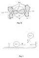
- Fig. 4schematically shows an object 4.0, for example, a connection of a robot, which is moved parallel to a horizontal surface 4.1 and at the same time in the direction of a vertical wall 4.2. Stopping object 4.0 on its orbit P in the event of a predicted collision with another object 4.0 'avoids colliding objects 4.0 and 4.0'. If, however, the object 4.0 is stopped away from the path P, a collision is prevented, but a collision with the horizontal surface 4.1 can result as a result. In addition, predicting a collision with the surface 4.1 would trigger an unwanted false alarm. Therefore, in the course of the inventive method, robot movements are preferably predicted and stopped along the path.
- Fig. 5shows the results.
- the paths of the two robotslead to a collision.
- the distance d between the robots as a function of time tis in Fig. 5a shown.
- Fig. 5bshows the distance d between the robots using the CAM.
- the relative movement of the robotsis stopped by the CAM before a collision occurs (d> 0 for all values of t).
- Fig. 5cshows how the robots approach and then move away from each other.
- the stopping timewas assumed to be constant. According to an alternative embodiment of the invention, the stopping time can be found by means of a previously stored look-up table.
- the inventionproposes to estimate the stopping time of the robot axes using neural networks NN for each joint of the robot in real time.
- a neural network according to the invention for estimating the stopping time for a Axis of a typical industrial robotis in Fig. 6 shown.
- a neural network NNis a computer architecture in which a plurality of elementary processors (nodes) 6.0 are connected to process information in parallel, thus forming a network.
- the structure of neural networksis derived from the structure of the human brain.
- Neural networksare used in particular for tasks that mimic human behavior, e.g. in methods for image recognition. They are known as such and therefore not described in detail here.
- the neural networks NN for the various axes of an industrial robothave a plurality of layers L2, L2, L3 of elementary processors or nodes 6.0 which are connected from layer to layer by signal paths 6.1.
- the layers L1, L2, L3are called input layer, intermediate layer and output layer, respectively.
- the nodes 6.0 of the input layer L1receive as input data the parameters which influence the stopping time of an axis, eg the axis velocity ⁇ and the payload m. This information propagates in the network NN and generates an estimate of the stopping time t s of the axis in the output layer L3, which is subsequently used for the collision detection according to the invention.
Landscapes
- Engineering & Computer Science (AREA)
- Mechanical Engineering (AREA)
- Automation & Control Theory (AREA)
- Robotics (AREA)
- Artificial Intelligence (AREA)
- Evolutionary Computation (AREA)
- Fuzzy Systems (AREA)
- Mathematical Physics (AREA)
- Software Systems (AREA)
- Physics & Mathematics (AREA)
- Manipulator (AREA)
- Numerical Control (AREA)
- Automobile Manufacture Line, Endless Track Vehicle, Trailer (AREA)
- Forklifts And Lifting Vehicles (AREA)
Abstract
Description
Translated fromGermanDie Erfindung betrifft ein Verfahren zum Vermeiden von Kollisionen zwischen einem Roboter und wenigstens einem anderen Objekt sowie eine Steuerungsvorrichtung, die zum Umsetzen des erfindungsgemäßen Kollisions-Vermeidungsverfahrens einsetzbar ist.The invention relates to a method for avoiding collisions between a robot and at least one other object and to a control device that can be used to implement the collision avoidance method according to the invention.
Nach einer allgemeinen Definition findet eine Kollision zwischen zwei Objekten A und B statt, wenn diese sich zur gleichen Zeit in demselben Raumbereich aufhalten. Diese Definition ist gleichbedeutend damit, dass wenigstens ein Punkt von A und ein Punkt von B durch dieselben Koordinaten bezüglich eines gemeinsamen Bezugssystems darstellbar sind.According to a general definition, a collision occurs between two objects A and B if they are in the same space at the same time. This definition is equivalent to allowing at least one point of A and one point of B to be represented by the same coordinates with respect to a common frame of reference.
Ein Roboter und weitere Objekte, zwischen denen Kollisionen vermieden werden sollen, werden für gewöhnlich als zusammenwirkende Vorrichtungen bezeichnet, da sie in einem bestimmten industriellen Verfahren zusammenarbeiten. Die Zusammenarbeit kann entweder eine aktive (im Falle der Zusammenarbeit eines Roboters mit einem anderen Roboter als Beispiel für eine zusammenwirkende Vorrichtung) oder eine passive sein. Bei modernen Industrierobotern, die sich mit erheblichen Geschwindigkeiten bewegen, führen Kollisionen in der Regel zu ernsthaften Schäden sowohl an den Robotern als auch an den von diesen gehandhabten Werkstücken und können zu kostspieligen Produktionsausfällen führen. Daher müssen derartige Kollisionen mit allen Mitteln verhindert werden, wenn Industrieroboter effizient eingesetzt werden sollen.A robot and other objects between which collisions are to be avoided are commonly referred to as cooperative devices because they work together in a particular industrial process. Collaboration can be either an active (in the case of collaboration of a robot with another robot as an example for a cooperative device) or passive. In modern industrial robots that move at significant speeds, collisions typically cause serious damage to both the robots and the workpieces they handle, and can result in costly production losses. Therefore, such collisions must be prevented by all means, if industrial robots are to be used efficiently.
Verschiedene Arten von Kollisionen können innerhalb eines Arbeitsbereiches, d.h. eines Raumbereiches, den sich ein Roboter und andere (bewegliche) Objekte teilen, erfolgen. Zum Klassifizieren von Kollisionen müssen verschiedene Faktoren berücksichtigt werden, insbesondere (i) der Typ der zu berücksichtigenden Objekte, z.B. Roboter/Maschinen, stationäre Objekte usw.; (ii) der Kollisionsgrund, z.B. Bahnänderungen, Veränderung von Sensordaten, Programmierfehler usw.; (iii) die Produktionsphase, z.B. ob die Kollision während der Lernphase (manueller Betrieb), der Validierungsphase (automatischer Betrieb) oder während der normalen Produktion (automatischer Betrieb mit vorzugsweise hohen Geschwindigkeiten) erfolgt:Different types of collisions may occur within a workspace, i. a space area shared by a robot and other (moving) objects. To classify collisions, various factors must be considered, in particular (i) the type of objects to be considered, e.g. Robots / machines, stationary objects, etc .; (ii) the collision cause, e.g. Path changes, change of sensor data, programming errors, etc .; (iii) the production phase, e.g. whether the collision occurs during the learning phase (manual operation), the validation phase (automatic operation) or during normal production (automatic operation at preferably high speeds):
Ein passives stationäres Objekt ist ein Objekt, das sich an einem festen Ort innerhalb des Arbeitsbereiches befindet und eine unveränderliche Form aufweist. Beispiele für passive stationäre Objekte sind Tische, Stangen usw. Derartige Objekte sind offensichtlich nicht durch irgendeine Steuerungseinrichtung gesteuert. Allerdings kann für derartige Objekte ein statisches Geometriemodell erstellt und gespeichert werden, so dass eine Kollisionsüberprüfung stattfinden kann. Dabei ist zwischen dem Körper eines Roboters (bestehend aus sogenannten Verbindungen, s.u.) und der Last (Werkzeuge oder Werkstücke) zu unterscheiden. Zwischen dem Körper eines Roboters und einem Objekt kann ein ständiges Kollisionspotential bestehen. Das Kollisionspotential zwischen einem Werkzeug und dem Objekt besteht so lange, wie das Werkzeug nicht mit einem auf dem Objekt verankerten Bezugssystem - steuerungstechnisch - verbunden ist. Sobald eine solche steuerungsrelevante Verbindung geschaffen wurde und sich das Werkzeug in einem mit dem Objekt verknüpften Bezugssystem bewegt, besteht grundsätzlich kein Kollisionspotential zwischen dem Werkzeug und dem Objekt, ausgenommen bei manuellem Betrieb, beispielsweise Lernphasen, oder im Falle von Programmierfehlern.A passive stationary object is an object that is located in a fixed location within the work area and has a fixed shape. Examples of passive stationary objects are tables, bars, etc. Such objects are obviously not controlled by any controller. However, for such objects, a static geometry model can be created and stored so that a collision check can take place. A distinction must be made between the body of a robot (consisting of so-called connections, see below) and the load (tools or workpieces). Between the body of a robot and an object can be a constant Collision potential exist. The collision potential between a tool and the object exists as long as the tool is not connected to a reference system anchored on the object - in terms of control technology. As soon as such a control-relevant connection has been created and the tool moves in a reference system linked to the object, there is fundamentally no potential for collision between the tool and the object, with the exception of manual operation, for example learning phases, or in the case of programming errors.
Ein aktives stationäres Objekt ist ein Objekt, das sich an einem festen Ort innerhalb des Arbeitsbereiches befindet, darüber hinaus jedoch eine veränderliche Form aufweist. Beispiele für aktive stationäre Objekte sind Einbauten und Paletten, die je nach Beladung variable Höhen aufweisen. Für gewöhnlich werden derartige Objekte nicht durch Robotersteuerungen gesteuert, so dass letztere keinerlei Informationen bezüglich des Zustandes (offen/geschlossen, Höhe usw.) besitzen. Daher ist eine Kollisionsüberprüfung mit derartigen Objekten schwierig. Allerdings kann die Kollisionswahrscheinlichkeit beseitigt werden, indem das Objekt als ein passives stationäres Objekt behandelt wird, dessen Volumen dem größtmöglichen Volumen des aktiven stationären Objektes entspricht. Die vorstehend beschriebene Unterscheidung zwischen dem Körper des Roboters und einer Last ist auch hier zu berücksichtigen.An active stationary object is an object that is located at a fixed location within the work area, but has a variable shape beyond. Examples of active stationary objects are installations and pallets which have variable heights depending on the load. Usually, such objects are not controlled by robot controls, so that the latter have no information regarding the state (open / closed, height, etc.). Therefore, collision checking with such objects is difficult. However, the collision probability can be eliminated by treating the object as a passive stationary object whose volume corresponds to the largest possible volume of the active stationary object. The above-described distinction between the body of the robot and a load is also to be considered here.
Ein bewegliches Objekt ist ein Objekt, dessen Stellung (Ort und Ausrichtung) innerhalb des Arbeitsbereiches nicht festliegt. Ein Beispiel für ein bewegliches Objekt ist eine Kiste auf einem Förderband. Ein Überprüfen und Vermeiden von Kollisionen mit einem solchen Objekt erfordert aktuelles Wissen bezüglich seiner Stellung.A moving object is an object whose position (location and orientation) within the workspace is not fixed. An example of a moving object is a box on a conveyor. Checking and avoiding collisions with such an object requires up-to-date knowledge of its position.
Bahnänderungen können sowohl erwartet als auch unerwartet sein. Eine erwartete Bahnänderung ist eine Änderung, die dem betrachteten industriellen Prozess inhärent ist und innerhalb bekannter Grenzen erfolgt. Eine derartige Änderung kann auf der Grundlage sensorischer Daten erfolgen, die den Roboter veranlassen, sich bei jedem Prozesszyklus auf einer anderen Bahn zu bewegen. Eine unerwartete Bahnänderung ist eine große oder kleine Änderung, die erfolgt, obwohl die Bahn eigentlich unveränderlich ist, oder die einen bestimmten Veränderungsgrenzwert überschreitet. Veränderungen bei an sich konstanter Bahn können z.B. von Nullpunktverschiebungen herrühren. Dramatische Veränderungen jenseits der Grenzen von erwarteten Veränderungen können das Ergebnis eines Sensorausfalls oder unbehandelter Fehler, wie z.B. ein ungesichertes Teil auf einem Förderer sein, das außerhalb der gewöhnlichen Ablagefläche abgelegt ist.Track changes can be both expected and unexpected. An expected path change is a change inherent in the considered industrial process and occurs within known limits. Such a change may be based on sensory data that causes the robot to move on a different path each process cycle. An unexpected orbit change is a big or small change that occurs even though the orbit is actually fixed or exceeds a certain change threshold. Changes in per se constant trajectory may e.g. originate from zero offsets. Dramatic changes beyond the limits of expected changes may account for the result of a sensor failure or untreated errors, such as failure. an unsecured part on a conveyor, which is stored outside the usual storage area.
Darüber hinaus kann eine Vielzahl von Programmierfehlern zu Kollisionen führen. Solche Kollisionen können während der Überprüfungsphase oder gewöhnlicher Produktionsphasen erfolgen.In addition, a variety of programming errors can lead to collisions. Such collisions may occur during the verification phase or during normal production phases.
Kollisionen können auch während des Erlernens oder Wiederanfahrens von Punkten eines Bewegungsablaufs erfolgen, wenn Benutzerfehler oder unerwartete Bewegungen auftreten. Nachdem die Punkte gelehrt oder wieder angefahren worden sind, können Kollisionen während der Validierung aufgrund unerwarteter Programmierfehler auftreten. Selbst für den Fall, dass die Lern-/Wiederanfahr-Phasen kollisionsfrei waren, können Kollisionen noch während der normalen Produktion als Folge von Bahnänderungen oder Programmierfehlern erfolgen, die während der früheren Phasen nicht offenbar geworden sind. Grund hierfür kann sein, dass mehrere ungewöhnliche Umstände zeitgleich auftreten.Collisions may also occur while learning or restarting points of a motion sequence when user errors or unexpected movements occur. After the points have been taught or restarted, collisions may occur during validation due to unexpected programming errors. Even in the event that the learn / restart phases were collision free, collisions may still occur during normal production as a result of path changes or programming errors that have not been revealed during the earlier phases. The reason for this may be that several unusual circumstances occur at the same time.
Dokument
Andere Ansätze finden bei der Offline-Programmierung Verwendung, bei der kollisionsfreie Bahnen für die Maschinen (Roboter und andere zusammenwirkende Vorrichtungen) innerhalb des gemeinsamen Arbeitsbereiches generiert werden. Allerdings erfordern derartige Verfahren eine genaue Vorkenntnis der Roboterbahnen. Darüber hinaus müssen die Bahnen aller Maschinen im Arbeitsbereich repetierend sein, d.h. die Bewegungsbahnen müssen sich unverändert wiederholen und dürfen nicht durch externe Sensoren oder Vorränge beeinflussbar sein.Other approaches are used in off-line programming where collision-free webs for the machines (robots and other cooperating devices) are generated within the shared workspace. However, such methods require a precise knowledge of the robot tracks. In addition, the paths of all machines in the work area must be repetitive, i. the trajectories must repeat unchanged and must not be influenced by external sensors or Vorränge.
Bekannte Robotersteuerungen detektieren in der Regel eine Kollision erst, nachdem eine solche stattgefunden hat. Dazu wird unter Verwendung eines dynamischen Maschinenmodells ein Motorstrom bestimmt. Wenn der tatsächlich gemessene Strom den Modellstrom um einen bestimmten Wert überschreitet, wird eine Kollision angenommen und das System gestoppt, um den Schaden zu minimieren.Known robot controls usually detect a collision only after such has taken place. For this purpose, a motor current is determined using a dynamic machine model. If the actual measured current exceeds the model current by a certain amount, a collision is assumed and the system is stopped to minimize the damage.
Der Erfindung liegt die Aufgabe zugrunde, das Problem von Kollisionen zwischen Robotern mit ihresgleichen bzw. ihrer Umgebung unter Vermeidung der vorstehend genannten Nachteile des Standes der Technik zu lösen.The invention has for its object to solve the problem of collisions between robots with their own or their environment while avoiding the above-mentioned disadvantages of the prior art.
Dazu schafft die Erfindung ein Verfahren der eingangs genannten Art, das regelmäßig beinhaltet:For this purpose, the invention provides a method of the type mentioned, which regularly includes:
Bestimmen einer Anhaltzeit für eine automatisch oder manuell gesteuerte Roboterbewegung auf der Grundlage gegenwärtiger und früherer Gelenkstellungen und Gelenkgeschwindigkeiten für jedes Robotergelenk;
Vorhersagen einer Konfiguration einer Bewegungsbahn des Roboters bei der Anhaltzeit;
Überprüfen der vorhergesagten Konfiguration mittels Abstands-/Behinderungsalgorithmen bezüglich einer Behinderung von Teilen des Roboters durch Teile der anderen Objekte oder umgekehrt; und
Anhalten des Roboters und/oder der anderen Objekte im Falle einer drohenden Kollision.Determining a stopping time for an automatically or manually controlled robot movement based on current and past joint positions and joint speeds for each robot joint;
Predicting a configuration of a trajectory of the robot at the stop time;
Checking the predicted configuration by means of distance / obstruction algorithms regarding obstruction of parts of the robot by parts of the other objects or vice versa; and
Stop the robot and / or the other objects in case of imminent collision.
Im Rahmen der Erfindung wird die vorhergesagte Konfiguration unter Verwendung der Anhaltzeiten bestimmt, wobei angenommen ist, dass der Roboter sich mit seiner aktuellen Beschleunigung ausgehend von seiner aktuellen Stellung und Geschwindigkeit weiterbewegt. Auf diese Weise liefern die vorhergesagten Bewegungsbahnen eine sogenannte Anhaltkonfiguration, die als solche bezeichnet wird, obwohl sie für gewöhnlich eine von Null verschiedene Geschwindigkeit aufweist.In the context of the invention, the predicted configuration is determined using the stopping times, assuming that the robot continues to move with its current acceleration from its current position and speed. In this way, the predicted trajectories provide a so-called stopping configuration, referred to as such, although usually having a non-zero velocity.
Um Kollisionen zu verhindern, werden demnach Konfigurationen nicht nur zur gegenwärtigen Zeit bezüglich Kollisionen überprüft, sondern auch zu einer zukünftigen Zeit, die ausreichend ist, damit die Maschinen vor einer ungewollten Berührung sicher stoppen können.Thus, to prevent collisions, configurations are checked for collision not only at the present time, but also at a future time sufficient is, so that the machines can stop safely from an accidental contact.
Nach einer Weiterbildung des erfindungsgemäßen Verfahrens wird der Roboter entlang seiner Bewegungsbahn abgebremst und kommt damit auf dieser zum Stehen. Auf diese Weise kann der Betrieb direkt aus der Anhaltstellung wiederaufgenommen werden, ohne dass weitere Stellungskorrekturen vorzunehmen wären oder es zu einem Werkstückausschuss käme. Darüber hinaus stellt eine Anhalten der Maschinen auf ihren Bahnen sicher, dass keine Kollisionen während der Abbremsphase auftreten.According to a development of the method according to the invention, the robot is braked along its trajectory and thus comes to a standstill on this. In this way, the operation can be resumed directly from the stop position, without further positional corrections would be made or it would come to a workpiece committee. In addition, stopping the machines on their tracks ensures that no collisions occur during the deceleration phase.
Nach einer weiteren Ausgestaltung der Erfindung wird der Roboter ohne Beachtung seiner eigentlichen Bewegungsbahn abgebremst und stoppt damit in der Regel abseits seiner Bahn. Das bedeutet, dass jede Roboterachse von ihrer gegenwärtigen Geschwindigkeit auf Null abgebremst wird, wobei ein einstellbarer Bremsverlauf vorgegeben sein kann. Dies kann mittels Kurzschluss-Bremsen geschehen, wobei die Antriebe durch mechanische Bremsen und durch Generatorbetrieb abgebremst werden. Ein derartiger Bremsvorgang ist ratsam, wenn ein Antrieb aus irgendeinem Grund nicht längs der Bahn gestoppt werden kann, beispielsweise wenn die Bahnsteigung zu steil ist.According to a further embodiment of the invention, the robot is decelerated without regard to its actual trajectory and thus usually stops off its path. This means that each robot axis is decelerated from its current speed to zero, with an adjustable braking course can be specified. This can be done by means of short-circuit braking, whereby the drives are braked by mechanical brakes and by generator operation. Such a braking operation is advisable if, for some reason, a drive can not be stopped along the track, for example if the track pitch is too steep.
Um Kollisionen vorherzusagen oder bezüglich ihres Auftretens zu überprüfen, ist es erforderlich, die Abstände zwischen den Teilen des Roboters und der anderen Objekte zu ermitteln. Dies beinhaltet die Bestimmung des Abstands zwischen geometrischen Approximationen der betroffenen Gegenstände, bei denen es sich entweder um einfache Formen wie Quader oder Kugeln oder um komplexe Polyeder, d.h. vielflächige geschlossene geometrische Gebilde handeln kann. Die am meisten verbreitete Methode zum Bestimmen von Abständen zwischen konvexen Polyedern ist die Methode nach Gilbert-Johnson-Keerthi (GJK), eine iterative Methode, die die Geometrie in Simplexen unterteilt, bis sie zu einem minimalen Abstand zwischen den beiden Objekten konvergiert. Dabei ist abzuwägen zwischen der Genauigkeit der Näherung und der Leistungsfähigkeit (Ausführungszeit) des Kollisions-Detektionsalgorithmus', der im Rahmen der Erfindung zum Einsatz kommt. So stellt beispielsweise die Beschreibung aller Verbindungen eines Roboters durch einhüllende Zylinder, Quader oder Kugeln eine eher konservative Approximation dar, ermöglicht jedoch eine schnelle Ausführbarkeit des Kollisions-Detektionsalgorithmus'. Andererseits bedingt eine genauere Approximation der Verbindungsstruktur durch Polyeder eine geringere Leistungsfähigkeit des Kollisions-Detektionsalgorithmus'. Daher beinhaltet die geometrische Behinderungsüberprüfung nach einer bevorzugten Ausgestaltung der Erfindung ein Bestimmen von Abständen zwischen geometrischen Approximationen, die verschiedene Genauigkeitsstufen aufweisen, die gemäß einer gewünschten Genauigkeit der Abstandsüberprüfung geprüft werden. Beispielsweise ist es nicht erforderlich, die genaueren Approximationen zu überprüfen, wenn die betreffenden Strukturen weit voneinander entfernt sind.To predict collisions or check for their occurrence, it is necessary to determine the distances between the parts of the robot and the other objects. This involves determining the distance between geometric approximations of the affected objects, which may be either simple shapes such as cuboids or spheres, or complex polyhedra, ie polyhedral closed geometric shapes. The most common method for determining distances between convex polyhedra is the method of Gilbert-Johnson-Keerthi (GJK), an iterative method that divides the geometry into simplexes until it converges to a minimum distance between the two objects. It is necessary to balance between the accuracy of the approximation and the performance (execution time) of the collision detection algorithm, which is used in the invention. Thus, for example, the description of all connections of a robot by enclosing cylinders, cuboids or spheres represents a rather conservative approximation, but enables rapid execution of the collision detection algorithm. On the other hand, a more accurate approximation of the interconnect structure by polyhedra requires less performance of the collision detection algorithm. Therefore, according to a preferred embodiment of the invention, the geometric disability check includes determining distances between geometric approximations having different degrees of accuracy that are tested according to a desired accuracy of the distance check. For example, it is not necessary to check the more accurate approximations if the structures in question are far apart.
Das Erstellen von geometrischen Approximationen ist eine anspruchsvolle und zeitintensive Aufgabe. Allerdings gibt es bereits kommerziell verfügbare Software, die automatisch CAD-Modelle in Geometriedateien übersetzt, die sich mit Kollisions-Detektionsalgorithmen verwenden lassen.Creating geometric approximations is a challenging and time-consuming task. However, there is already commercially available software that automatically translates CAD models into geometry files that can be used with collision detection algorithms.
Kollisionsvermeidung beinhaltet eine genaue Vorgabe der Bewegungsbahnen. Da die Bewegung von Industrierobotern hinreichend gleichmäßig und ruckfrei erfolgt, sind relativ einfache Konfigurations-Vorhersagealgorithmen zum Vorhersagen der Bewegungsbahnen ausreichend. Ausgehend von den tatsächlichen Stellungen und Geschwindigkeiten jedes einzelnen Gelenkes i zu gegenwärtigen und frühren Zeiten lässt sich die Bewegungsbahn des Gelenks - ausgedrückt als zukünftige Gelenkstellung θi - mittels der Beziehung:
t-k, t-k = t-k*Δt (k=1,2,3,...), abgeschätzt werden, wobei Δt das Überprüfungs-Zeitintervall bezeichnet, dessen Dauer der Abtastperiode der Robotersteuerung entsprechen und demgemäß beispielsweise Werte um 12 ms annehmen kann. Die Gelenkstellung θ und die Gelenkgeschwindigkeit θ̇ sind gegeben als Winkelstellung (Einheit: Grad) bzw Winkelgeschwindigkeit (Grad/s).Collision avoidance involves an exact specification of the trajectories. Because the movement of industrial robots is sufficiently uniform and smooth, relatively simple configuration prediction algorithms are sufficient to predict the trajectories. Starting from the actual Positions and velocities of each joint i at present and early times allows the trajectory of the joint - expressed as future joint position θi - by means of the relationship:
t-k , t-k = tk * Δt (k = 1,2,3, ...), where Δt denotes the verification time interval whose duration corresponds to the sampling period of the robot controller and accordingly, for example, values around 12 ms can accept. The joint position θ and the joint velocity θ̇ are given as angular position (unit: degree) or angular velocity (degree / s).
Nach einer bevorzugten Ausgestaltung der Erfindung wird die Geschwindigkeit θ̇i des Gelenks i ausgehend von der Gelenkstellung θi,0 zur gegenwärtigen Zeit t und zu früheren Zeiten t-k unter Verwendung des Gear'schen Verfahrens, d.h. mittels der Beziehung:
cf = 1/(12Δt), c0 = 25, c1 = -48, c2 = 36, c3 = -16, c4 = 3.According to a preferred embodiment of the invention, the velocity θi of the joint i is calculated from the joint position θi, 0 at the present time t and at earlier times tk using the Gear method, ie by the relationship:
cf = 1 / (12Δt), c0 = 25, c1 = -48, c2 = 36, c3 = -16, c4 = 3.
Gleichfalls wird die Beschleunigung γi des Gelenkes i ausgehend von der Gelenkgeschwindigkeit θ̇i,0 ; zur gegenwärtigen Zeit t und zu früheren Zeiten t-k, t-k = t-k*Δt, unter Verwendung von
Nach einer weiteren Ausgestaltung der Erfindung umfasst die Konfigurationsvorhersage und Behinderungsüberprüfung:
- Bestimmen eines Anhaltabstands θi,stop des Gelenkes i gemäß θi,stop = θ̇i,02 /(2γi,max), wobei γi,max eine maximale negative Beschleunigung des Gelenkes bezeichnet;
- Addieren des Anhaltabstands zu der gegenwärtigen Stellung des Gelenkes, um so eine Konfiguration nach der Anhaltezeit zu erhalten; und Bestimmen eines Abstands zwischen Teilen des Roboters und der anderen Objekte bei dieser Konfiguration. Hierbei handelt es sich um einen eher konservativen Zugang: Beispielsweise betragen die maximale Geschwindigkeit und die maximale negative Beschleunigung des ersten Gelenkes eines Standard-Industrieroboters 240 Grad/s bzw. 880 Grad/s2. Daher beträgt der Anhaltewinkel des Gelenkes bei maximaler Geschwindigkeit etwa 33 Grad. Aufgrund dieses großen Anhalteabstands könnte für die Anhaltekonfiguration eine Kollision vorausgesagt werden, obwohl die geplante Bewegungsbahn eigentlich kollisionsfrei ist.
- Determining a stopping distance θi, stopping the joint i according to θi, stop = θi, 02 / (2γi, max ), where γi, max denotes a maximum negative acceleration of the joint;
- Adding the stopping distance to the current position of the joint so as to obtain a configuration after the stopping time; and determining a spacing between parts of the robot and the other objects in this configuration. This is a more conservative approach: for example, the maximum velocity and the maximum negative acceleration of the first joint of a standard industrial robot are 240 degrees / s and 880 degrees / s2, respectively. Therefore, the stopping angle of the joint at maximum speed is about 33 degrees. Because of this large stopping distance, a collision could be predicted for the stopping configuration, although the intended trajectory is actually collision free.
Um die Genauigkeit der Stellungsvorhersage zu verbessern, ist nach einer Weiterentwicklung des erfindungsgemäßen Verfahrens vorgesehen, einen Filter auf die Gelenkstellungsund Geschwindigkeitsdaten anzuwenden, die zur Stellungsvorhersage benutzt werden. Vorzugsweise wird der Filter im Zeitbereich auf die Daten angewendet. Nach einer weiteren bevorzugten Ausgestaltung der Erfindung geschieht die Filterung durch Berechnen eines laufenden Mittels, welches die Daten effektiv glättet und auf diese Weise vor allem die hochfrequenten Anteile herausfiltert, die vor allem im Zuge abrupter Richtungswechsel der Roboterbewegung (Sprünge) auftreten. Die Filterlänge kann an die gewünschte Vorhersagegenauigkeit oder Irregularität des Bewegungsprofils angepasst werden. Alternativ dazu kann die Filterung auch im Frequenzbereich erfolgen.In order to improve the accuracy of the position prediction, it is provided according to a further development of the method according to the invention to apply a filter to the joint position and velocity data used for position prediction. Preferably, the filter is applied to the data in the time domain. According to a further preferred embodiment of the invention, the filtering is done by calculating a running means, which effectively smoothes the data and in this way filters out especially the high-frequency components that occur especially in the course of abrupt change of direction of the robot movement (jumps). The filter length can be adjusted to the desired prediction accuracy or motion profile irregularity. Alternatively, the filtering can also be done in the frequency domain.
Die Anhaltzeit einer Roboterachse hängt von den folgenden Parametern ab:
- Achsgeschwindigkeit: Je höher die Geschwindigkeit desto länger dauert es, den Roboter abzubremsen.
- Maximale erlaubte Geschwindigkeitsabnahme: Je größer die maximale erlaubte Geschwindigkeitsabnahme, desto weniger Zeit wird benötigt, um den Roboter abzubremsen;
- Roboterkonfiguration: Da die Trägheit des Roboters von seiner Konfiguration abhängt, hängt auch die Anhaltzeit einer gegebenen Achse von den Werten der verbleibenden Achsen ab, insbesondere von den Achsen am Ende der kinematischen Kette, d.h. in Richtung des distalen Endes des Roboters.
- Nutzlast: Je schwerer die Last und je größer ihre Trägheit, desto mehr Zeit wird benötigt, um den Roboter abzubremsen.
- Axle speed: The higher the speed, the longer it takes to decelerate the robot.
- Maximum allowable deceleration: The greater the maximum allowable deceleration, the less time it will take to decelerate the robot;
- Robot configuration: Since the inertia of the robot depends on its configuration, the stopping time of a given axis also depends on the values of the remaining axes, in particular the axes at the end of the kinematic chain, ie in the direction of the distal end of the robot.
- Payload: The heavier the load and the greater its inertia, the more time it will take to decelerate the robot.
Die Anhaltzeit lässt sich anhand einer Nachschlagtabelle abschätzen. Allerdings schafft die Erfindung eine Vorrichtung zum Abschätzen der Anhaltzeiten der Achsen in einer Art und Weise, die trotz der großen Anzahl von Parametern auch für Echtzeit-Anwendungen geeignet ist:The stopping time can be estimated using a lookup table. However, the invention provides a device for estimating the stopping times of the axles in a manner which, despite the large number of parameters, is also suitable for real-time applications:
Aus diesem Grund ist zwecks weiterer Verbesserung sowohl der Genauigkeit als auch der Geschwindigkeit der Ermittlung der Anhaltzeit nach einer Weiterentwicklung der Erfindung vorgesehen, dass zur Konfigurationsvorhersage und Behinderungsüberprüfung wenigstens ein neuronales Netz zum Abschätzen von Anhaltzeiten für die Roboterachsen eingesetzt wird. Nach einer bevorzugten Ausgestaltung wird für jedes Robotergelenk ein neuronales Netz verwendet. Dadurch wird die Abschätzung der Anhaltzeit flexibler und lässt sich besser an eine bestimmte Situation anpassen.For this reason, in order to further improve both the accuracy and the speed of determining the stopping time according to a further development of the invention, at least one neural network is used for estimating stopping times for the robot axes for configuration prediction and obstruction checking. According to a preferred embodiment, a neural network is used for each robot joint. This makes the estimation of the stopping time more flexible and better adaptable to a specific situation.
Zu diesem Zweck verwendet das erfindungsgemäße Verfahren mehrschichtige neuronale Netze (NN) mit möglicher Rückübertragung von Informationen innerhalb des Netzes. Die neuronalen Netze verarbeiten als Eingangswerte die Parameter, die die Anhaltzeit der Achsen beeinflussen, und liefern eine Abschätzung der Anhaltzeit. Die neuronalen Netze werden mit Datensätzen trainiert, die durch Messung am Roboter gewonnen wurden. Die Trainings-Datensätze sollten den gesamten Bereich der relevanten Parameter abdecken und dabei eine oder mehrere Einflussgrößen wie Gelenkgeschwindigkeiten, Gelenkwinkel, Gelenkstellungen, Stellungen und Geschwindigkeiten der Roboterbasis sowie Werkzeug- oder Lastmassen beinhalten. Sobald die neuronalen Netze trainiert sind, können sie zur genauen Abschätzung der Anhaltzeiten eingesetzt werden.For this purpose, the method according to the invention uses multilayer neural networks (NN) with possible retransmission of information within the network. The neural networks process as input values the parameters which influence the stopping time of the axes and provide an estimate of the stopping time. The neural networks are trained with data sets obtained by measurement on the robot. The training datasets should cover the full range of relevant parameters, including one or more factors such as joint speeds, joint angles, joint positions, robotic base positions and velocities, and tool or load masses. Once the neural networks are trained, they can be used to accurately estimate the stopping times.
Nach einer Weiterentwicklung des erfindungsgemäßen Verfahrens enthält die Arbeitsbereich-Beschreibungsdatei Zeiger auf geometrische Approximationsdateien, die zum Beschreiben aller Objekte im Arbeitsbereich notwendig sind.According to a further development of the method according to the invention, the workspace description file contains pointers to geometric approximation files, which are necessary for describing all objects in the work area.
Nach einer alternativen Ausgestaltung des erfindungsgemäßen Verfahrens wird eine Kopie der Arbeitsbereich-Beschreibungsdatei in jeder Steuerung im Arbeitsbereich, d.h. in jeder zusammenwirkenden Vorrichtung unterhalten und aktualisiert. Darüber hinaus wird die Arbeitsbereich-Beschreibungsdatei zumindest dann aktualisiert, wenn eine geometrische Veränderung innerhalb des Arbeitsbereichs erfolgt, z.B. durch Befestigen eines neuen Werkzeugs am Roboter. Die Aktualisierung kann auch im Bereich des Echtzeit-Betriebssystems erfolgen.According to an alternative embodiment of the method according to the invention, a copy of the work area description file is maintained and updated in each control in the work area, ie in each cooperating device. In addition, the workspace description file is updated at least when a geometric change occurs within the workspace, eg, by attaching a new tool to the robot. The update can also be done in the area of the real-time operating system.
Die meisten Roboteranwendungen erfordern ein gewisses Maß an zulässiger und gesteuerter Berührung, beispielsweise bei der Materialhandhabung, beim Schweißen usw. Daher muss die Robotersteuerung wissen, dass derartige Kontakte nicht wie potentiell gefährliche Kollisionen behandelt werden müssen, die zu einem Abbruch der Roboterbewegung führen. Aus diesem Grund wird im Vorfeld einer erlaubten Berührung zwischen dem Roboter und einem Objekt, z.B. während eines Handhabungsvorgangs, eine Verbindung geschaffen, die dafür sorgt, dass der Roboter und ggf. das Objekt während einer nachfolgenden "Kollision" nicht angehalten werden. Die Verbindung kann nach Beendigung der erlaubten Berührung wieder aufgelöst werden.Most robotic applications require some allowable and controlled contact, for example, in material handling, welding, etc. Therefore, the robot controller must know that such contacts do not have to be treated as potentially dangerous collisions that lead to robot motion being aborted. For this reason, in advance of allowable contact between the robot and an object, e.g. During a handling operation, a connection is created which ensures that the robot and possibly the object are not stopped during a subsequent "collision". The connection can be released after the permitted contact has been terminated.
In diesem Zusammenhang muss unterschieden werden zwischen Situationen, in denen alle Maschinen in einem Arbeitsbereich sich längs bekannter, vorgegebener Bahnen bewegen, und Situationen, in denen die Bahnen in Echtzeit modifiziert werden, beispielsweise durch sensorische Informationen (Kameras oder dergleichen). Erstere werden im folgenden als "synchron" bezeichnet, während letztere "asynchron" genannt werden. Derartige Situationen ergeben sich auch im Verhältnis zwischen einem Roboter und einem Werkzeug, welches dieser benutzt. Ein Bestandteil des Arbeitsbereichs ist mit einem anderen Bestandteil verbunden, wenn sich ersterer in einem Bezugssystem bewegt, welches an letzterem angeheftet ist. Damit ist die Relativbewegung zwischen den beiden Bestandteilen synchron und es existiert keine potentielle Kollision zwischen ihnen, solange die Verbindung besteht. Beispielsweise führt eine Bewegung einer der beiden Bestandteile, wie eines ersten Roboters, zu einer entsprechenden Bewegung des anderen Bestandteils, wie eines zweiten Roboters. Auf diese Weise ist das (räumliche) Verhältnis der beiden konstant. Ein Kollisionspotential kann vor Schaffung der Verbindung bestehen, oder nachdem die Verbindung gelöst worden ist. Demnach ist ein Werkzeug, das mit einem Werkstück in Berührung kommt, mit dem Werkstück verbunden. Es bewegt sich daher in einem Bezugssystem, das an das Werkstück angeheftet ist. Der Vorgang ist demzufolge synchron, und es existiert kein Kollisionspotential zwischen dem Werkzeug und dem Werkstück. Allerdings handelt es sich bei bis zu 90% der im alltäglichen Einsatz von Industrierobotern auftretenden Fälle um asynchrone Fälle.In this context, a distinction must be made between situations in which all machines in a work area move along known, predetermined paths and situations in which the tracks are modified in real time, for example by sensory information (cameras or the like). The former are called "synchronous" in the following, while the latter are called "asynchronous". Such situations also arise in the relationship between a robot and a tool, which uses this. One part of the workspace is connected to another part when the former moves in a frame of reference attached to the latter. Thus, the relative movement between the two components is synchronous and there is no potential collision between them as long as the connection exists. For example, a movement of one of the two components, such as a first robot, results in a corresponding movement of the other component, such as a second robot. In this way, the (spatial) ratio of the two is constant. A collision potential may exist before the connection is established or after the connection has been solved. Thus, a tool that comes into contact with a workpiece is connected to the workpiece. It therefore moves in a frame of reference attached to the workpiece. The process is therefore synchronous, and there is no collision potential between the tool and the workpiece. However, up to 90% of the cases occurring in everyday use of industrial robots are asynchronous cases.
Um das vorstehend beschriebene Verfahren bei einem Roboter zur Kollisionsvermeidung zwischen dem Roboter und wenigstens einem anderen Objekt einsetzen zu können, schlägt die Erfindung weiterhin eine Steuerungsvorrichtung vor, die aufweist: Mittel zum regelmäßigen Bestimmen einer Anhaltezeit für eine automatisch oder manuell gesteuerte Roboterbewebung auf der Grundlage gegenwärtiger und frührer Gelenkstellungen und Gelenkgeschwindigkeiten für jedes Robotergelenk; Mittel zum regelmäßigen Vorhersagen einer Konfiguration einer Bewegungsbahn des Roboters nach den Anhaltezeiten; Mittel zum regelmäßigen Überprüfen der vorhergesagten Konfiguration mittels Abstands-/Behinderungs-Algorithmen bezüglich einer Behinderung von Teilen des Roboters durch Bestandteile der anderen Objekte, und Mittel zum Anhalten des Roboters und/oder der anderen Objekte im Falle einer drohenden Kollision.In order to be able to use the above-described method in a robot for collision avoidance between the robot and at least one other object, the invention further proposes a control apparatus comprising: means for regularly determining a stop time for an automatically or manually controlled robot weaving on the basis of current and, in particular, joint positions and joint velocities for each robotic joint; Means for periodically predicting a configuration of a trajectory of the robot after the stopping times; Means for regularly checking the predicted configuration by means of distance / obstruction algorithms relating to obstruction of parts of the robot by components of the other objects, and means for stopping the robot and / or the other objects in the event of an imminent collision.
Die erfindungsgemäße Steuerungsvorrichtung ist im folgenden als CAM (Collision Avoidance Manager) bezeichnet. Die CAM ist eine Steuerung, die für die Detektion von bzw. die Reaktion auf Kollisionen zwischen wenigstens zwei Bestandteilen des Arbeitsbereiches zuständig ist. In einem Arbeitsbereich kann mehr als eine CAM vorgesehen bzw. vorhanden sein.The control device according to the invention is referred to below as CAM (Collision Avoidance Manager). The CAM is a controller responsible for detecting or responding to collisions between at least two components of the workspace. In a workspace, more than one CAM may be provided.
Nach einer weiteren Ausgestaltung der erfindungsgemäßen Steuerungsvorrichtung besitzt diese Prozessormittel zum parallelen Ausführen von zwei Betriebssystemen, von denen eines ein Standard-PC-Betriebssystem und das andere ein Echtzeit-Betriebssystem zum Steuern der Roboterbewegung ist. Die Prozessormittel sind zum Ausführen eines Übersetzer-Programms für die Kommunikation zwischen dem PC- und dem Echtzeit-Betreibssystem ausgebildet. Auf diese Weise existiert für den Benutzer unter dem PC-Betriebssystem (z.B. Windows™) eine standardisierte Benutzeroberfläche, wodurch die Programmierung des Roboters sehr vereinfacht wird. Nach einer bevorzugten Ausgestaltung sind die Prozessormittel zum Ausführen von entsprechenden Teilen eines Programms ausgebildet, durch das ein Verfahren zur Kollisionsvermeidung implementiert ist. Nach einer weiteren Ausgestaltung der erfindungsgemäßen Steuerungsvorrichtung weist diese Speichereinheiten in Verbindung mit beiden Betriebssystemen zum Speichern von Geometriedaten für den Arbeitsbereich auf.According to a further embodiment of the control device according to the invention, this processor means has two operating systems in parallel, one of which is a standard PC operating system and the other is a real-time operating system for controlling the robot movement. The processor means are adapted to execute a translator program for the communication between the PC and the real-time operating system. In this way, the user under the PC operating system (e.g., Windows ™) has a standardized user interface, which greatly simplifies the programming of the robot. According to a preferred embodiment, the processor means are designed to execute corresponding parts of a program by which a method for collision avoidance is implemented. According to a further embodiment of the control device according to the invention, these memory units in conjunction with both operating systems for storing geometry data for the work area.
Wie bereits früher erwähnt, werden alle Informationen bezüglich Kollisionen (z.B. potentielle Kollisionen, Zeiger auf Geometriedateien usw.) in Speichereinheiten der CAM in speziellen Arbeitsbereich-Beschreibungsdateien gespeichert, die Arbeitsbereich-Diagramme (WorkCell Diagrams WCD) genannt werden. Für jeden Bestandteil des Arbeitsbereichs werden so Informationen bezüglich seiner potentiellen Kollisionen und Geometriedateien in den Speichereinheiten abgelegt. Diese Informationen werden in die Echtzeit-Steuerung geladen, so dass die vorstehend beschriebenen Kollisions-Vermeidungsaufgaben (Collision Avoidance Tasks CAT), beispielsweise die tatsächliche Vorhersage der Roboterbewegung und des Abbremsen auf oder abseits der Bahn gemäß des erfindungsgemäßen Verfahrens, diese in Echtzeit nutzen können.As mentioned earlier, all collision information (eg, potential collisions, pointers to geometry files, etc.) is stored in CAM memory units in special workspace description files called WorkCell Diagrams (WCD). For each part of the workspace, information about its potential collisions and geometry files is stored in the storage units. This information is loaded into the real-time controller so that the collision avoidance tasks (CAT) described above, such as the actual robot motion and on-track or off-lane deceleration according to the method of the invention, can use them in real time.
Um Kollisions-Informationen zwischen den beiden Betriebssystemen zu kommunizieren, beinhaltet die erfindungsgemäße Steuerungsvorrichtung ein Übersetzungsprogramm (Interpreter), das vorzugsweise unter dem Echtzeit-Betriebssystem läuft.In order to communicate collision information between the two operating systems, the control device according to the invention includes a translation program (interpreter), which preferably runs under the real-time operating system.
Da ein Arbeitsbereich mehrere CAM in Verbindung mit einer Mehrzahl von kollisionsüberwachten Robotern oder dergleichen beinhalten kann, umfasst die erfindungsgemäße Steuerungsvorrichtung Prozessormittel zumindest in Verbindung mit dem Echtzeit-Betriebssystem, die für die Kommunikation mit den Echtzeit-Betriebssystemen entsprechender anderer Steuerungsvorrichtungen in einem gemeinsamen Arbeitsbereich ausgebildet sind. Die dadurch definierte Steuerungs-Kommunikationsaufgabe erhält Daten von den entsprechenden Robotersteuerungen (diejenigen Steuerungen, für die eine bestimmte CAM Kollisionen detektiert).Since a work area may include multiple CAMs in conjunction with a plurality of collision-monitored robots or the like, the control device of the present invention includes processor means at least in connection with the real-time operating system configured to communicate with the real-time operating systems of other control devices in a shared workspace , The control communication task defined thereby receives data from the corresponding robot controllers (those controllers for which a particular CAM detects collisions).
Kommunikation zwischen Steuerungen ist eine Voraussetzung für viele Aspekte des Zusammenwirkens von Robotern. Damit die erfindungsgemäße Kollisionsvermeidung funktioniert, müssen verschiedene Daten an die CAM übermittelt werden. Die CAM muss die Konfiguration aller Bestandteile des Arbeitsbereichs kennen. Daher sind für jeden Roboter oder jedes Objekt, das die CAM überwacht, die folgenden Wert zu übermitteln:
- Gelenkwerte: Diese definieren die Konfiguration des Roboters bezüglich seiner Basis;
- Basiskoordinaten: Diese definieren die Verbindung mit den Gelenkwerten die Konfiguration des Roboters im Arbeitsbereich. Die Basis kann selbst beweglich sein, beispielsweise wenn der Roboter auf einer Schiene angeordnet ist;
- Gelenkgeschwindigkeiten und Basisgeschwindigkeiten: Diese werden in den Kollisions-Vorhersagealgorythmen verwendet. Dabei ist die Geschwindigkeit des Basis-Bezugssystems für die Steuerung nicht ohne weiteres verfügbar und muss unter Verwendung von Daten gemessen oder geschätzt werden, die eine externe Maschine, die die Roboterbasis bewegt, zur Verfügung stellt;
- Werkstückänderungen;
- Werkzeugänderungen;
- Änderungen des Bewegungsziels; und
- Änderungen des Kollisionspotentials.
- Joint Values: These define the configuration of the robot relative to its base;
- Base Coordinates: These define the connection with the hinge values the configuration of the robot in the work area. The base itself can be mobile, for example when the robot is disposed on a rail;
- Joint Speeds and Base Speeds: These are used in collision prediction algorithms. In doing so, the speed of the base reference system is not readily available to the controller and must be measured or estimated using data provided by an external machine moving the robot base;
- Workpiece changes;
- Tool changes;
- Changes of the movement goal; and
- Changes in the collision potential.
Werkzeug- und Werkstückänderungen am Roboter, der durch die CAM gesteuert wird, werden durch den Interpreter an die Echtzeit-Steuerung übermittelt.Tool and workpiece changes to the robot controlled by the CAM are communicated through the interpreter to the real-time controller.
Nach einer Weiterbildung der Erfindung weist die Steuerungsvorrichtung zusätzlich eine Eingabeeinrichtung zum Eingeben von Geometriedaten für den Arbeitsbereich auf. Auf diese Weise kann eine externe CAD-Geometriedatei der CAM einfach zur Verfügung gestellt werden. Die Eingabeeinrichtung kann beispielsweise als Diskettenlaufwerk oder Netz-Verbindungseinrichtung ausgebildet sein.According to a development of the invention, the control device additionally has an input device for inputting geometry data for the work area. In this way, an external CAD geometry file can easily be made available to the CAM. The input device may be formed, for example, as a floppy disk drive or network connection device.
Aus der vorstehenden Beschreibung ist ersichtlich, dass die vorliegende Erfindung sich durch eine Vielzahl an Vorteilen gegenüber dem Stand der Technik auszeichnet:From the foregoing description it will be seen that the present invention is characterized by a number of advantages over the prior art:
Der Benutzer muss beim Programmieren eines Roboters keinerlei Vorkehrungen zur Kollisionsvermeidung treffen, wie ein Definieren gemeinsamer Arbeitsbereiche. Darüber hinaus kann das erfindungsgemäße Verfahren als Absicherung zusammen mit vorbekannten expliziten Verfahren eingesetzt werden.The user need not make any collision avoidance arrangements when programming a robot, such as defining common workspaces. In addition, the method according to the invention can be used as protection together with previously known explicit methods.
Weiterhin ermöglicht das erfindungsgemäße Verfahren ein automatisches Einrichten des Arbeitsbereiches vom Standpunkt der Kollisionsvermeidung. Es ermittelt automatisch, welche Teile ein Kollisionsrisiko bezüglich welcher anderen Teile aufweisen.Furthermore, the method according to the invention makes it possible to automatically set up the working area from the standpoint of collision avoidance. It automatically determines which parts have a risk of collision with respect to which other parts.
Da das erfindungsgemäße Verfahren darauf aufbaut, die Konfigurationen der bewegten Teile über einen Zeitraum vorauszusagen, der lang genug ist, um die Maschinen sicher abzubremsen, und anschließend diese Konfigurationen bezüglich möglicher Behinderungen überprüft, müssen die Bewegungsbahnen zuvor nicht bekannt sein. Wird eine Kollision vorausgesagt, so werden die Maschinen entlang oder abseits ihrer Bahn gestoppt.Since the method of the present invention is based on predicting the configurations of the moving parts over a period of time long enough to safely decelerate the machines and then checking those configurations for possible obstructions, the trajectories need not be previously known. If a collision is predicted, the machines will be stopped along or off track.
Da vor allem die Lern- und Validierungsphasen sich durch langsame Geschwindigkeiten auszeichnen, sind in diesen Phasen auch die Anhaltezeiten und -abstände sehr gering. Aus diesem Grund ist das erfindungsgemäße Verfahren in diesen Fällen besonders gut geeignet.Since, above all, the learning and validation phases are characterized by slow speeds, the stopping times and distances in these phases are also very low. For this reason, the method according to the invention is particularly well suited in these cases.
Kollisionen, die durch Programmierfehler oder unerwartete große Bahnänderungen hervorgerufen werden, führen zu einer Berührung von Objekten, die unter normalen Umständen jederzeit weit voneinander entfernt sein sollten. In diesen Fällen ist das Vorhersagen einer Anhaltekonfiguration unter Umständen zu aufwändig und nicht erforderlich. Es reicht in diesen Fällen aus, den Abstand zwischen den entsprechenden Objekten zu überwachen und diese abzustoppen, falls sie sich einander bis auf einem bestimmten vorgegebenen Abstand annähern. Dieses vereinfachte Verfahren lässt sich in jeder Arbeitsphase und für jede Bewegungsgeschwindigkeit anwenden, wenn die Abstandsschwelle groß genug gewählt werden kann. Ist dies nicht der Fall, so ist das vorstehend beschriebene genauere Verfahren anzuwenden.Collisions caused by programming errors or unexpected large web changes will result in touching objects that should normally be far apart under normal circumstances. In these cases, predicting a stop configuration may be too cumbersome and unnecessary. It is sufficient in these cases, the distance between the corresponding Monitor objects and stop them if they approach each other to a certain predetermined distance. This simplified method can be used at any working phase and for any speed of movement, if the distance threshold can be chosen large enough. If this is not the case, then the more accurate method described above should be used.
Bevorzugte Ausgestaltungen der Erfindung sind im folgenden mit Blick auf die Zeichnungen beschrieben. Es zeigt:
- Fig. 1
- ein Ablaufdiagramm des erfindungsgemäßen Verfahrens zur Kollisionsvermeidung;
- Fig. 2
- ein Blockschaltbild einer Robotersteuerung für den Einsatz des erfindungsgemäßen Verfahrens;
- Fig. 3
- schematische Darstellungen mit verschiedenen geometrischen Approximationen eines Roboters und seiner Teile bzw. Verbindungen;
- Fig. 4
- eine schematische Darstellung einer Roboterbewegung in der Nähe eines Hindernisses;
- Fig. 5
- Ergebnisse einer numerischen Simulation einer Kollisionsbewegung zweier Roboter; und
- Fig. 6
- eine schematische Darstellung eines dreischichtigen neuronalen Netzes, das zur Vorhersage der Anhaltzeit in Verbindung mit dem erfindungsgemäßen Verfahren zur Kollisionsvermeidung eingesetzt wird.
- Fig. 1
- a flow diagram of the method according to the invention for collision avoidance;
- Fig. 2
- a block diagram of a robot controller for the use of the method according to the invention;
- Fig. 3
- schematic representations with different geometric approximations of a robot and its parts or connections;
- Fig. 4
- a schematic representation of a robot movement in the vicinity of an obstacle;
- Fig. 5
- Results of a numerical simulation of a collision movement of two robots; and
- Fig. 6
- a schematic representation of a three-layer neural network, which is used to predict the stopping time in connection with the method according to the invention for collision avoidance.
Sensordaten S vom Roboter und/oder aus dem Arbeitsbereich, z.B. Gelenkwinkel und Gelenkgeschwindigkeiten des Roboters, Kamerabilder usw. werden dem Verfahren zur Kollisionsvermeidung 1.0 zur Verfügung gestellt und zusammen mit anderen Parametern, wie der Nutzlast oder der Roboterkonfiguration, zum Abschätzen 1.2 der Anhaltzeit ts benutzt, z.B. mittels neuronaler Netze, wie in Verbindung mit
Mittels der abgeschätzten Zeit ts sagt ein Algorithmus eine Roboterbahn während der Anhaltezeit voraus 1.3, die anschließend bei 1.4 zur Behinderungsüberprüfung benutzt wird, die ein Überprüfen des Abstandes zwischen Bestandteilen des Arbeitsbereichs umfasst. Wenn eine zukünftige Kollision detektiert wird, stoppt der Roboter 1.5a. Dies kann entweder längs der Roboterbahn oder abseits geschehen, beispielsweise durch einfaches mechanisches Bremsen. Wird keine Kollision detektiert 1.5b, so beginnt ein neuer Steuerzyklus C'.By means of the estimated time ts , an algorithm predicts a robot path during the stopping time 1.3, which is then used at 1.4 for the disability check, which involves checking the distance between components of the work area. When a future collision is detected, the robot stops 1.5a. This can be done either along the robot path or offside, for example, by simple mechanical braking. If no collision is detected 1.5b, then a new control cycle C 'begins.
Das im vorstehenden unter Bezugnahme auf
Innerhalb des Arbeitsbereichs 2.1 gemäß
Die PC-Bereiche PC der CAM 2.0, 2.0' weisen Prozessormittel PM1 und Speichereinheiten SM auf, die in beispielhafter Weise dargestellt und zum Ausführen und/oder Speichern zeitlich unabhängiger Geometriedateien 2.3, eines Arbeitsbereichs-Diagramms (WCD) 2.4 mit allen Informationen über Kollisionen im Arbeitsbereich 2.1 während einer programmierten Roboterbewegung M sowie zum Ausführen eines speziellen Programms 2.5 zum Kodifizieren einer Roboterbewegung M ausgebildet sind. Die Echtzeit-Bereiche RT der CAM 2.0, 2.0' weisen Prozessormittel PM2 und Speichereinheiten SM auf, die beispielhaft dargestellt und zum Ausführen und/oder Speichern eines Interpreters 2.6 zum Kommunizieren dynamischer Werkstück-/Werkzeugveränderungen 2.7 an der durch die CAM 2.0, 20' gesteuerten Vorrichtung an die RT ausgebildet sind. Die RT enthalten zusätzlich Geometriedaten 2.8, auf die eine Kollisionsvermeidungs-Aufgabe (Collision Avoidance Task CAT) 2.9 zugreift. Die CAT 2.9 erhält Eingangsdaten von einer Kommunikationsaufgabe 2.10, die den RT einer CAM 2.0 mit den RT unterschiedlicher CAM 2.0' und Robotersteuerungen 2.2, 2.2' verbindet. In der gezeigten Ausgestaltung teilen sich der PC und der RT der CAM 2.0 gemeinsame Speichereinheiten SM.The PC areas PC of the CAM 2.0, 2.0 'have processor means PM1 and memory units SM, which are shown in an exemplary manner and for executing and / or storing temporally independent geometry files 2.3, a work area diagram (WCD) 2.4 with all information about collisions in the Work area 2.1 during a programmed robot movement M and to execute a special program 2.5 for codifying a robot movement M are formed. The real-time regions RT of the CAM 2.0, 2.0 'comprise processor means PM2 and memory units SM exemplified and for executing and / or storing an interpreter 2.6 for communicating dynamic workpiece / tool changes 2.7 at the CAM 2.0, 20' controlled Device to the RT are formed. The RT additionally contain geometry data 2.8, which is accessed by a Collision Avoidance Task (CAT) 2.9. The CAT 2.9 receives input data from a communication task 2.10, which connects the RT of a CAM 2.0 with the RT of different CAM 2.0 'and robot controllers 2.2, 2.2'. In the embodiment shown, the PC and the RT of the CAM 2.0 share common memory units SM.
Die Geometriedatei 2.11, die den Arbeitsbereich 2.1 beschreibt, wird entweder im Arbeitsbereich 2.1 selbst oder außerhalb des Arbeitsbereichs 2.1 mittels CAD oder durch Offline-Simulation erzeugt. Eine Dateneingabe 2.12 der Geometriedatei 2.11 zu den PC der CAM 2.0, 2.0' geschieht über eine Netzverbindung oder ein Diskettenlaufwerk (in letzterem Fall mittels entnehmbarer Datenträger; nicht gezeigt).The geometry file 2.11, which describes the workspace 2.1, is created either in the workspace 2.1 itself or outside of the workspace 2.1 by means of CAD or offline simulation. Data entry 2.12 of the geometry file 2.11 to the PC of the CAM 2.0, 2.0 'takes place via a network connection or a floppy disk drive (in the latter case by means of removable data carriers, not shown).
Da die Robotersteuerung 2.2, 2.2' denselben Aufbau wie konventionelle Steuerungen besitzen, wird auf eine detaillierte Beschreibung verzichtet. Einzelheiten betreffend einer Robotersteuerung 2.2, 2.2' mit zwei Betriebssystemen findet sich in
Sämtliche Informationen bezüglich Kollisionen, die sich aus der zur Verfügung gestellten Geometriedatei 2.3 ergeben, werden im WCD 2.4 gespeichert. In diesem Zusammenhang existieren zwei Arten von potentiellen Kollisionen: Bedingte potentielle Kollisionen (Conditional Potential Collisions CPC) und unbedingte potentielle Kollisionen (Un-Conditional Potential Collisions Ü-CPC). Eine CPC illustriert den Fall, wenn die potentielle Kollision nur unter bestimmten Umständen zwischen zwei Bestandteilen in einem Arbeitsbereich 2.1 gegeben ist. Beispielsweise könnte ein Werkstück X potentiell mit einem Werkzeug Y kollidieren, wenn Werkstück X durch einen bestimmten ersten Roboter unter Verwendung von Werkzeug Z gehandhabt und zugleich Werkzeug Y an einem bestimmten zweiten Roboter montiert ist. In allen anderen Fällen sind Werkstück X und Werkzeug Y so weit voneinander entfernt, dass kein Kollisionspotential existiert. Eine U-CPC beschreibt den Fall, wenn das Kollisionspotential zu allen Zeiten zwischen den Bestandteilen existiert. Beispielsweise kann eine U-CPC zwischen bestimmten Verbindungen zweier Roboter bestehen, wenn die Arbeitsvolumina, d.h. die von den beiden Robotern erreichbaren Raumbereiche sich zu allen Zeiten überlappen. Eine spezielle Eigenschaft der Geometriedatei im WCD 2.4 verweist auf die geometrische Approximation, die mit dem Gegenstand, z.B. dem Inhalt des Arbeitsbereichs 2.1, zu verwenden ist. Ein lokaler Teilsatz des WCD 2.4 wird in jeder CAM 2.0, 2.0' unterhalten und aktualisiert. Auf diese Weise kennt jede CAM 2.0, 2.0' alle potentiellen Verhältnisse im Arbeitsbereich 2.1. Bei einer Veränderung der Geometrie des Arbeitsbereichs 2.1, beispielsweise einer Werkzeugänderung, fügt ein spezieller Programmeditor (nicht gezeigt), der in Verbindung mit dem WCD 2.4 eingesetzt wird, eine entsprechende Anweisung in das Programm 2.5 ein, das den Interpreter 2.6 veranlasst, die dynamischen Werkzeug-/Werkstückinformationen 2.7 im RT zu aktualisieren, die den zeitlich veränderlichen Teil der Geometriedatei 2.3 beinhalten und auf die die CAT 2.9, die für die tatsächliche Vorhersage der Roboterbewegung und das im Gefährdungsfalle notwendige Abstoppen der Maschinen verantwortlich ist, in Echtzeit zugreifen kann.All collision information resulting from the provided geometry file 2.3 is stored in WCD 2.4. There are two types of potential collisions in this context: Conditional Potential Collisions (CPC) and Unconditional Potential Collisions (Ü-CPC). A CPC illustrates the case when the potential collision is only given under certain circumstances between two components in a workspace 2.1. For example, a workpiece X could potentially collide with a tool Y when workpiece X is rotated by a particular first robot using Tool Z handled and at the same time tool Y is mounted on a particular second robot. In all other cases, workpiece X and tool Y are so far apart that no collision potential exists. A U-CPC describes the case when the collision potential exists at all times between constituents. For example, a U-CPC may exist between certain connections of two robots when the volumes of work, ie the areas of space reachable by the two robots, overlap at all times. A special property of the geometry file in WCD 2.4 refers to the geometric approximation to be used with the object, eg the content of the workspace 2.1. A local subset of the WCD 2.4 is maintained and updated in each CAM 2.0, 2.0 '. In this way every CAM 2.0, 2.0 'knows all potential conditions in the workspace 2.1. When changing the geometry of the workspace 2.1, such as a tool change, a special program editor (not shown) used in conjunction with the WCD 2.4 inserts a corresponding instruction into the program 2.5, which causes the interpreter 2.6, the dynamic tool - to update workpiece information 2.7 in the RT which contains the time-varying part of the geometry file 2.3 and which can be accessed in real time by the CAT 2.9, which is responsible for the actual prediction of the robot movement and the stopping of the machines in case of danger.
Die dynamischen Werkzeug-/Werkstückinformationen 2.7 im RT der CAM 2.0, 2.0' umfassen Zeiger auf die Geometriedaten 2.8, die auch im RT enthalten und deshalb für die CAT 2.9 zur effizienten Kollisionsvermeidung in Echtzeit zugänglich sind. Die Ausführung der CAT 2.9 wird auch durch die Ausgabe der Kommunikationsaufgabe 2.10 beeinflusst, die eine Verbindung zwischen den RT weiterer CAM 2.0' und/oder Robotersteuerungen 2.2, 2.2' zur Verfügung stellt, sofern diese im Arbeitsbereich 2.1 vorhanden sind. Dies geschieht entweder durch direkte Kommunikation oder durch Veränderungen der Geometriedaten 2.8 und/oder der dynamischen Werkstück/Werkzeuginformationen 2.7 innerhalb des RT der CAM 2.0.The dynamic tool / workpiece information 2.7 in the RT of the CAM 2.0, 2.0 'includes pointers to the geometry data 2.8, which are also contained in the RT and therefore accessible to the CAT 2.9 for efficient collision avoidance in real time. The execution of CAT 2.9 is also affected by the output of communication task 2.10, which is a connection between the RTs of other CAM 2.0 'and / or robot controllers 2.2, 2.2 ', provided that they are available in the work area 2.1. This is done either by direct communication or by changing the geometry data 2.8 and / or the dynamic workpiece / tool information 2.7 within the RT of the CAM 2.0.
Die geometrischen Approximationen 3.2 - 3.4 der Verbindungen 3.1 eines Roboters 3.0 sind in der Geometriedatei 2.3 und den Geometriedaten 2.8 in Speichereinheiten SM der CAM 2.0, 2.0' gespeichert, so dass die CAT 2.9 in Echtzeit auf sie zugreifen kann, um so den eigentlichen erfindungsgemäßen Kollisions-Vermeidungsalgorithmus auszuführen.The geometric approximations 3.2-3.4 of the connections 3.1 of a robot 3.0 are in the geometry file 2.3 and the geometry data 2.8 in memory units SM of the CAM 2.0, 2.0 ', so that the CAT 2.9 can access them in real time so as to carry out the actual collision avoidance algorithm according to the invention.
Behinderungsüberprüfung geschieht mittels bekannter Techniken, wie dem Verfahren von Gilbert, Johnson und Keerthi (GJK), welches ein iteratives Verfahren darstellt, bei dem die Geometrie in Simplexen unterteilt wird, bis sie zum minimalen Abstand zwischen den beiden Objekten hin konvergiert. Derartige Verfahren sind nicht Gegenstand der eigentlichen Erfindung und daher hier nicht weiter erläutert.Disability screening is done using known techniques, such as the method of Gilbert, Johnson, and Keerthi (GJK), which is an iterative method of dividing the geometry into simplexes until it converges to the minimum distance between the two objects. Such methods are not the subject of the actual invention and therefore not further explained here.
Um das erfindungsgemäße Verfahren zur Vermeidung von Kollisionen zu überprüfen, wurden numerische Simulationen der Bewegung von zwei identischen Robotern 3.0, wie in
Die Ergebnisse sind in
In der mit Blick auf
Ein neuronales Netz NN ist eine Rechnerarchitektur, in der eine Mehrzahl von Elementarprozessoren (Knoten) 6.0 zum parallelen Verarbeiten von Informationen verbunden sind und auf diese Weise ein Netz bilden. Die Struktur neuronaler Netze ist von der Struktur des menschlichen Gehirns abgeleitet.A neural network NN is a computer architecture in which a plurality of elementary processors (nodes) 6.0 are connected to process information in parallel, thus forming a network. The structure of neural networks is derived from the structure of the human brain.
Neuronale Netze werden insbesondere für Aufgaben eingesetzt, die menschliches Verhalten imitieren, z.B. bei Verfahren zur Bilderkennung. Sie sind als solche bekannt und deshalb hier nicht detailliert beschrieben.Neural networks are used in particular for tasks that mimic human behavior, e.g. in methods for image recognition. They are known as such and therefore not described in detail here.
Die neuronalen Netze NN für die verschiedenen Achsen eines Industrieroboters weisen eine Mehrzahl von Schichten L2, L2, L3 aus Elementarprozessoren oder Knoten 6.0 auf, die von Schicht zu Schicht durch Signalpfade 6.1 verbunden sind. Die Schichten L1, L2, L3 heißen Eingabeschicht, Zwischenschicht bzw. Ausgabeschicht. Die Knoten 6.0 der Eingabeschicht L1 erhalten als Eingabedaten die Parameter, die die Anhaltzeit einer Achse beeinflussen, z.B. die Achsengeschwindigkeit θ̇ und die Nutzlast m. Diese Information breitet sich im Netz NN aus und erzeugt eine Abschätzung der Anhaltzeit ts der Achse in der Ausgabeschicht L3, die anschließend für die erfindungsgemäße Kollisionsdetektion benutzt wird.The neural networks NN for the various axes of an industrial robot have a plurality of layers L2, L2, L3 of elementary processors or nodes 6.0 which are connected from layer to layer by signal paths 6.1. The layers L1, L2, L3 are called input layer, intermediate layer and output layer, respectively. The nodes 6.0 of the input layer L1 receive as input data the parameters which influence the stopping time of an axis, eg the axis velocity θ̇ and the payload m. This information propagates in the network NN and generates an estimate of the stopping time ts of the axis in the output layer L3, which is subsequently used for the collision detection according to the invention.
- 1.01.0
- Verfahren zur KollisionsvermeidungMethod for collision avoidance
- 1.11.1
- Initialisierungsphaseinitialization
- 1.21.2
- Abschätzung der AnhaltzeitEstimation of the stopping time
- 1.31.3
- KonfigurationsvorhersageConfiguration Forecast
- 1.41.4
- BehinderungsüberprüfungInterference checking
- 1.5a1.5a
- Anhalten des RobotersStopping the robot
- 1.5b1.5b
- Fortsetzung der BewegungContinuation of the movement
- 2.0, 2.0'2.0, 2.0 '
- Steuerung zur Kollisionsvermeidung CAMControl for collision avoidance CAM
- 2.12.1
- ArbeitsbereichWorkspace
- 2.2, 2.2'2.2, 2.2 '
- Robotersteuerungrobot control
- 2.32.3
- Geometriedateigeometry file
- 2.42.4
- Arbeitsbereich-Beschreibungsdatei WCDWorkspace description file WCD
- 2.52.5
- Programmprogram
- 2.62.6
- Interpreterinterpreter
- 2.72.7
- dynamische Werkzeug-/Werkstückveränderungdynamic tool / workpiece change
- 2.82.8
- Geometriedatengeometry data
- 2.92.9
- Kollisions-Vermeidungsaufgabe CATCollision avoidance task CAT
- 2.102.10
- Kommunikationsaufgabecommunication task
- 2.112.11
- Erzeugen der GeometriedateiGenerate the geometry file
- 2.122.12
- Dateneingabedata entry
- 3.03.0
- Roboterrobot
- 3.13.1
- Verbindungconnection
- 3.23.2
- Approximation (Quader, Zylinder)Approximation (cuboid, cylinder)
- 3.33.3
- Approximation (Kugel)Approximation (sphere)
- 3.43.4
- Approximation (Polyeder)Approximation (polyhedron)
- 4.0, 4.0'4.0, 4.0 '
- Objektobject
- 4.14.1
- horizontale Oberflächehorizontal surface
- 4.24.2
- vertikale Wandvertical wall
- 6.06.0
- Knoten/ElementarprozessorNode / processor unit
- 6.16.1
- Signalpfadsignal path
- C, C'C, C '
- Steuerzykluscontrol cycle
- dd
- Abstanddistance
- L1L1
- Eingabeschichtinput layer
- L2L2
- Zwischenschichtinterlayer
- L3L3
- Ausgabeschichtoutput layer
- MM
- Roboterbewegungrobot motion
- mm
- Nutzlastpayload
- NNNN
- neuronales Netzneural network
- P, P'P, P '
- Bahntrain
- PCPC
- Standard-PC-Bereich/-BetriebssystemStandard-PC segment / operating system
- PM1, PM2PM1, PM2
- Prozessormittelprocessor means
- RTRT
- Echtzeit-Bereich-/BetriebssystemReal-time Scope / OS
- SS
- Sensordatensensor data
- SMSM
- Speichereinheitstorage unit
- tt
- ZeitTime
- tsts
- Anhaltezeitstopping time
- Δt.delta.t
- Zeitintervalltime interval
- γγ
- Beschleunigungacceleration
- θθ
- Winkelangle
- θ̇.theta
- Geschwindigkeitspeed
Claims (30)
- A method of avoiding collisions between a robot and at least one other object, a stopping time being determined for an automatically or manually controlled robot movement,characterised by the following steps:- determining the stopping time on the basis of current and past joint positions and velocities of each joint of a robot comprising such joints;- predicting a configuration of a trajectory of the robot at said stopping time;- checking the predicted configuration of the trajectory through distance/interference algorithms concerning interference of robot components with components of said other objects or vice versa; and- stopping the robot and/or said other objects in the event of an imminent collision on the predicted trajectory.
- A method according to claim 1, wherein the robot is stopped on its path.
- A method according to claim 1, wherein the robot is stopped off its path.
- A method according to one of claims 1 to 3, wherein interference checking involves determining distances between geometric approximations of components of the robot and said other objects.
- A method according to claim 4, wherein said geometric approximations have different levels of accuracy which are checked according to a desired accuracy in distance checking.
- A method according to one of the preceding claims, wherein forecasting the trajectory of a joint involves application of a relationship:

where θi is a predicted position of joint i, where θi,0 and θi,0 are a position and a velocity of joint i at a current time t, respectively, where ti,s is the stopping time of joint i, and where γi is an estimated current joint acceleration. - A method according to claim 6, wherein a velocity of joint i is estimated from the joint position at a current time and at earlier times using:

where θi,k=θi(t-k),t-k=t-k·Δt, and
cf =1 1/(12Δt), c0 = 25,c1 = -48,c2 = 36,c3 = -16,c4 = 3 . - A method according to claim 7, wherein the acceleration of joint i is estimated from the joint velocity at a current time and at earlier times, using:

- A method according to claim 8, wherein configuration forecasting and interference checking involves: determining a stopping distance of joint i from

where γi,max is a maximum negative acceleration of the joint;
adding the stopping distance to the actual position of the joint to obtain a configuration over the stopping time; and
determining a distance between robot components and said other objects at said configuration. - A method according to one of the preceding claims, wherein a filter is applied to the joint position and velocity data used for position prediction.
- A method according to claim 10, wherein said filter is applied in the time domain.
- A method according to claim 11, wherein said filter is a running average.
- A method according to one of the preceding claims, wherein configuration forecasting and interference checking involves using at least one neural network to estimate stopping times of the robot axes.
- A method according to claim 13, wherein one neural network is used for each robot joint.
- A method according to claim 14, wherein input to said neural networks includes one or more element(s) from a group comprising joint velocities, joint angles, joint positions, robot base positions, robot base velocities and tool or load masses.
- A method according to one of the preceding claims, wherein all acquired information concerning collisions is stored in a workcell description file for communication to a real-time operating system responsible for controlling the robot movement.
- A method according to claim 16, wherein the workcell description file contains pointers to geometric approximation files needed to describe all objects present in the workcell.
- A method according to claim 17, wherein a copy of the workcell description file is maintained and updated on each controller, i.e. on each cooperative mechanism present in the workcell.
- A method according to claim 18, wherein the workcell description file is updated at least when a geometric change happens in the workcell, e.g. mounting of a new tool to the robot.
- A method according to claim 19, wherein the workcell description file including a description of the geometric change is updated in the real-time operating system.
- A method according to one of the preceding claims, wherein prior to an allowed contact between the robot and an object, e.g. during a handling operation a link is established causing the robot and, where applicable, the object not to stop during a subsequent collision.
- A method according to claim 21, wherein the link is broken after the allowed contact operation is terminated.
- A control device for avoiding collisions between a robot and at least one other object, means for regularly determining a stopping time of an automatically or manually controlled robot movement,characterised by :- Configuring the means for determining the stopping time so as to determine the latter on the basis of current and past point positions and velocities for each robot joint;- means for regularly predicting a configuration of a trajectory of the robot after said stopping times;- means for regularly checking the predicted configuration through distance/interference algorithms regarding interference of robot .components with components of said other objects; and- means for stopping the robot and/or said other objects in the event of an imminent collision on the predicted trajectory.
- A control device according to claim 23, comprising processor means for running two operating systems in parallel, one of which being a standard PC operating system, the other one being a real-time operating system for controlling a robot motion.
- A control device according to claim 24, wherein said processor means at least in connection with the real-time operating system are designed for communication with real-time operating systems of other corresponding control devices present in the same workcell.
- A control device according to claim 25, further comprising an input device for inputting workcell related geometric data.
- A control device according to claim 26, wherein the input device is a disk drive or a network connection device.
- A control device according to one of claims 24 to 27, wherein said processor means are devised for running an interpretation program for communication between the PC and the real-time operating systems.
- A control device according to one of claims 24 to 28, wherein said processor means are devised for running respective parts of a program implementing a collision avoidance method, in particular a method as described in preceding claims 1 to 22.
- A control device device according to one of claims 24 to 29, comprising memory units in conjunction with both operating systems for storing workcell related geometry data.


Applications Claiming Priority (2)
| Application Number | Priority Date | Filing Date | Title |
|---|---|---|---|
| US159701 | 2002-05-30 | ||
| US10/159,701US6678582B2 (en) | 2002-05-30 | 2002-05-30 | Method and control device for avoiding collisions between cooperating robots |
Publications (3)
| Publication Number | Publication Date |
|---|---|
| EP1366867A2 EP1366867A2 (en) | 2003-12-03 |
| EP1366867A3 EP1366867A3 (en) | 2006-09-06 |
| EP1366867B1true EP1366867B1 (en) | 2009-01-21 |
Family
ID=29419711
Family Applications (1)
| Application Number | Title | Priority Date | Filing Date |
|---|---|---|---|
| EP03010669AExpired - LifetimeEP1366867B1 (en) | 2002-05-30 | 2003-05-13 | Method and device for avoiding collisions between industrial robots and other objects |
Country Status (6)
| Country | Link |
|---|---|
| US (1) | US6678582B2 (en) |
| EP (1) | EP1366867B1 (en) |
| JP (1) | JP2004001217A (en) |
| CN (1) | CN100380259C (en) |
| AT (1) | ATE421410T1 (en) |
| DE (1) | DE50311112D1 (en) |
Cited By (7)
| Publication number | Priority date | Publication date | Assignee | Title |
|---|---|---|---|---|
| DE102017215519A1 (en)* | 2017-09-05 | 2019-03-07 | Robert Bosch Gmbh | Method and device for collision detection for a vehicle |
| DE102016013475B4 (en) | 2015-11-20 | 2019-10-02 | Fanuc Corporation | Manual feeder of a robot for calculating an operating range of a robot |
| DE102018133472B3 (en)* | 2018-12-21 | 2020-03-12 | Franka Emika Gmbh | Motion monitoring of a robot manipulator |
| EP3907754A1 (en) | 2020-05-05 | 2021-11-10 | Integrated Dynamics Engineering GmbH | Method for processing substrates, in particular wafers, masks or flat panel displays, with a semiconductor industry machine |
| DE102020112149A1 (en) | 2020-05-05 | 2021-11-11 | Integrated Dynamics Engineering Gesellschaft mit beschränkter Haftung | Procedure for the control of handling systems |
| DE102012103830B4 (en) | 2011-05-05 | 2022-05-25 | Fanuc Robotics America Corp. | Method and computer-readable media for automatic connection of deadlocks in multiple robot systems |
| EP4321307A1 (en) | 2022-08-08 | 2024-02-14 | Siemens Aktiengesellschaft | Method for operating a modular robot, modular robot, collision protection system, computer program product |
Families Citing this family (211)
| Publication number | Priority date | Publication date | Assignee | Title |
|---|---|---|---|---|
| US8944070B2 (en) | 1999-04-07 | 2015-02-03 | Intuitive Surgical Operations, Inc. | Non-force reflecting method for providing tool force information to a user of a telesurgical system |
| US8004229B2 (en) | 2005-05-19 | 2011-08-23 | Intuitive Surgical Operations, Inc. | Software center and highly configurable robotic systems for surgery and other uses |
| US9517106B2 (en) | 1999-09-17 | 2016-12-13 | Intuitive Surgical Operations, Inc. | Systems and methods for commanded reconfiguration of a surgical manipulator using the null-space |
| JP2003133200A (en)* | 2001-10-19 | 2003-05-09 | Canon Inc | Simulation apparatus and simulation method |
| US6927395B2 (en)* | 2002-06-14 | 2005-08-09 | Koninklijke Philips Electronics N.V. | Gamma camera collision avoidance |
| DE10236392A1 (en)* | 2002-08-08 | 2004-02-19 | Kuka Roboter Gmbh | Method and device for controlling handling devices |
| DE10307261A1 (en)* | 2003-02-20 | 2004-09-09 | Siemens Ag | Programming platform for creating part programs for machine tools or production machines |
| DE10321241B4 (en)* | 2003-05-12 | 2005-09-29 | Siemens Ag | Monitoring method for a machine and objects corresponding thereto |
| JP2005081445A (en)* | 2003-09-04 | 2005-03-31 | Fanuc Ltd | Interference region confirmation device of robot |
| DE102004019285A1 (en)* | 2004-04-21 | 2005-11-10 | Bosch Rexroth Ag | Method for collision checking of two objects |
| DE102004027944B4 (en)* | 2004-06-08 | 2012-02-16 | Kuka Laboratories Gmbh | Method for protecting a robot against collisions |
| US9390203B2 (en) | 2004-06-15 | 2016-07-12 | Abb Ab | Method and system for off-line programming of multiple interacting robots |
| US9104197B2 (en)* | 2004-06-15 | 2015-08-11 | Abb Ab | Method and system for off-line programming of multiple interacting robots |
| JP4613539B2 (en)* | 2004-07-16 | 2011-01-19 | トヨタ自動車株式会社 | Robot motion planning method |
| AU2004322424B2 (en)* | 2004-07-19 | 2010-12-09 | Societe De Materiel Industriel Et D'equipement-Smie | Process and system for avoiding collisions for moveable machines |
| JP3907649B2 (en)* | 2004-09-02 | 2007-04-18 | ファナック株式会社 | Interference prevention control device between robots |
| AT502286B1 (en)* | 2004-09-15 | 2008-09-15 | Wfl Millturn Tech Gmbh & Co Kg | PROCEDURE FOR COLLISION PREVENTION |
| US7318767B2 (en)* | 2004-10-05 | 2008-01-15 | Ruger, Barthelt & Abel | Device and method for machine control |
| US8000837B2 (en) | 2004-10-05 | 2011-08-16 | J&L Group International, Llc | Programmable load forming system, components thereof, and methods of use |
| US7699021B2 (en)* | 2004-12-22 | 2010-04-20 | Sokudo Co., Ltd. | Cluster tool substrate throughput optimization |
| US7798764B2 (en) | 2005-12-22 | 2010-09-21 | Applied Materials, Inc. | Substrate processing sequence in a cartesian robot cluster tool |
| US7255747B2 (en) | 2004-12-22 | 2007-08-14 | Sokudo Co., Ltd. | Coat/develop module with independent stations |
| JP4382003B2 (en)* | 2005-03-23 | 2009-12-09 | 川崎重工業株式会社 | Robot control apparatus and robot control method |
| US20060241813A1 (en)* | 2005-04-22 | 2006-10-26 | Applied Materials, Inc. | Optimized cluster tool transfer process and collision avoidance design |
| US9789608B2 (en) | 2006-06-29 | 2017-10-17 | Intuitive Surgical Operations, Inc. | Synthetic representation of a surgical robot |
| JP4764070B2 (en)* | 2005-05-24 | 2011-08-31 | 本田技研工業株式会社 | Work station safety system |
| DE102005024822A1 (en)* | 2005-05-27 | 2006-11-30 | Müller Weingarten AG | Method for optimizing the transport movement of workpieces in transfer presses |
| FR2894318B1 (en)* | 2005-12-07 | 2008-03-07 | Lectra Sa | ACTIVE SECURITY MANAGEMENT METHOD FOR AN AUTOMATIC WORKING MACHINE. |
| WO2007121357A2 (en)* | 2006-04-13 | 2007-10-25 | Fanuc Robotics America, Inc. | Dynamic space check for multi-arm system moving on a rail |
| KR101477133B1 (en) | 2006-06-13 | 2014-12-29 | 인튜어티브 서지컬 인코포레이티드 | Minimally invasive surgical system |
| US12357400B2 (en) | 2006-06-29 | 2025-07-15 | Intuitive Surgical Operations, Inc. | Synthetic representation of a surgical robot |
| US10008017B2 (en) | 2006-06-29 | 2018-06-26 | Intuitive Surgical Operations, Inc. | Rendering tool information as graphic overlays on displayed images of tools |
| US10258425B2 (en) | 2008-06-27 | 2019-04-16 | Intuitive Surgical Operations, Inc. | Medical robotic system providing an auxiliary view of articulatable instruments extending out of a distal end of an entry guide |
| US9718190B2 (en) | 2006-06-29 | 2017-08-01 | Intuitive Surgical Operations, Inc. | Tool position and identification indicator displayed in a boundary area of a computer display screen |
| US20090192523A1 (en) | 2006-06-29 | 2009-07-30 | Intuitive Surgical, Inc. | Synthetic representation of a surgical instrument |
| DE102006048163B4 (en)* | 2006-07-31 | 2013-06-06 | Pilz Gmbh & Co. Kg | Camera-based monitoring of moving machines and / or moving machine elements for collision prevention |
| EP1901150B1 (en)* | 2006-09-14 | 2008-10-29 | Abb Research Ltd. | A method and device for avoiding collisions between an industrial robot and an object |
| DE502006009264D1 (en)* | 2006-09-30 | 2011-05-19 | Abb Technology Ag | Method and system for designing and checking safety areas of a robot |
| DE102007006708A1 (en) | 2007-02-10 | 2008-08-14 | Abb Research Ltd. | Method for securing a handling device |
| EP1972415B1 (en)* | 2007-03-23 | 2019-01-02 | Honda Research Institute Europe GmbH | Robots with collision avoidance functionality |
| EP1972416B1 (en)* | 2007-03-23 | 2018-04-25 | Honda Research Institute Europe GmbH | Robots with occlusion avoidance functionality |
| EP1974869A1 (en)* | 2007-03-26 | 2008-10-01 | Honda Research Institute Europe GmbH | Apparatus and method for generating and controlling the motion of a robot |
| DE102007016727B4 (en)* | 2007-04-07 | 2010-06-10 | Dematic Gmbh & Co. Kg | Method for multilayer stacking a carrier |
| JP4844453B2 (en)* | 2007-04-09 | 2011-12-28 | 株式会社デンソーウェーブ | Robot teaching apparatus and teaching method |
| US8046102B2 (en)* | 2007-05-17 | 2011-10-25 | Fanuc Robotics America, Inc. | Control method for synchronous high speed motion stop for multi-top loaders across controllers |
| US8989468B2 (en)* | 2007-05-25 | 2015-03-24 | Definiens Ag | Generating an anatomical model using a rule-based segmentation and classification process |
| US9089256B2 (en) | 2008-06-27 | 2015-07-28 | Intuitive Surgical Operations, Inc. | Medical robotic system providing an auxiliary view including range of motion limitations for articulatable instruments extending out of a distal end of an entry guide |
| US9084623B2 (en) | 2009-08-15 | 2015-07-21 | Intuitive Surgical Operations, Inc. | Controller assisted reconfiguration of an articulated instrument during movement into and out of an entry guide |
| US9138129B2 (en) | 2007-06-13 | 2015-09-22 | Intuitive Surgical Operations, Inc. | Method and system for moving a plurality of articulated instruments in tandem back towards an entry guide |
| US8903546B2 (en)* | 2009-08-15 | 2014-12-02 | Intuitive Surgical Operations, Inc. | Smooth control of an articulated instrument across areas with different work space conditions |
| US8620473B2 (en) | 2007-06-13 | 2013-12-31 | Intuitive Surgical Operations, Inc. | Medical robotic system with coupled control modes |
| US9469034B2 (en) | 2007-06-13 | 2016-10-18 | Intuitive Surgical Operations, Inc. | Method and system for switching modes of a robotic system |
| JPWO2009004686A1 (en)* | 2007-06-29 | 2010-08-26 | 富士通株式会社 | Transport device |
| DE102007033432A1 (en)* | 2007-07-18 | 2009-01-22 | Heidelberger Druckmaschinen Ag | Printing machine with electric crush protection |
| JP4298770B2 (en)* | 2007-08-28 | 2009-07-22 | ファナック株式会社 | Numerical control device with interference check function |
| JP2009090403A (en)* | 2007-10-05 | 2009-04-30 | Fanuc Ltd | Robot movement range setting device |
| CA2706296A1 (en)* | 2007-11-29 | 2009-06-04 | Airbus Operations Gmbh | Diagnosis system |
| CN101888920B (en)* | 2007-12-07 | 2012-10-03 | 株式会社安川电机 | Robot movement regulating method, robot system, and robot movement regulating device |
| JP4978494B2 (en)* | 2008-02-07 | 2012-07-18 | トヨタ自動車株式会社 | Autonomous mobile body and control method thereof |
| ES2553722T3 (en)* | 2008-02-20 | 2015-12-11 | Abb Research Ltd. | Method and system to optimize the configuration of a robot work cell |
| US8160765B2 (en)* | 2008-03-03 | 2012-04-17 | Cnh America Llc | Method and system for coordinated vehicle control with wireless communication |
| US9144904B2 (en) | 2008-05-21 | 2015-09-29 | Fanuc Robotics America Corporation | Method and system for automatically preventing deadlock in multi-robot systems |
| US8315738B2 (en)* | 2008-05-21 | 2012-11-20 | Fanuc Robotics America, Inc. | Multi-arm robot system interference check via three dimensional automatic zones |
| CN101592930B (en)* | 2008-05-30 | 2012-03-14 | 鸿富锦精密工业(深圳)有限公司 | Warehouse anticollision protection system and warehouse anticollision protection method |
| US12239396B2 (en) | 2008-06-27 | 2025-03-04 | Intuitive Surgical Operations, Inc. | Medical robotic system providing an auxiliary view including range of motion limitations for articulatable instruments extending out of a distal end of an entry guide |
| US8864652B2 (en) | 2008-06-27 | 2014-10-21 | Intuitive Surgical Operations, Inc. | Medical robotic system providing computer generated auxiliary views of a camera instrument for controlling the positioning and orienting of its tip |
| EP2332859B1 (en)* | 2008-09-05 | 2016-01-06 | Daifuku Co., Ltd. | Article storage facility and method of operating the same |
| CA2744333C (en)* | 2008-11-21 | 2015-11-03 | Dematic Corp. | Stacking apparatus and method of multi-layer stacking of objects on a support |
| ATE537943T1 (en) | 2009-01-14 | 2012-01-15 | Gfrt Fortschrittliche Robotertechnologie Gmbh & Co Kg | METHOD FOR CONTROLLING INDUSTRIAL ROBOTS |
| DE102009006256B4 (en) | 2009-01-27 | 2019-01-03 | Deutsches Forschungszentrum für künstliche Intelligenz GmbH | Method for avoiding collisions controlled moving parts of a plant |
| EP2411189B1 (en)* | 2009-03-27 | 2020-08-05 | Abb Ag | Intrinsically safe small robot and method for controlling this robot |
| US12266040B2 (en) | 2009-03-31 | 2025-04-01 | Intuitive Surgical Operations, Inc. | Rendering tool information as graphic overlays on displayed images of tools |
| US9492927B2 (en) | 2009-08-15 | 2016-11-15 | Intuitive Surgical Operations, Inc. | Application of force feedback on an input device to urge its operator to command an articulated instrument to a preferred pose |
| US8918211B2 (en) | 2010-02-12 | 2014-12-23 | Intuitive Surgical Operations, Inc. | Medical robotic system providing sensory feedback indicating a difference between a commanded state and a preferred pose of an articulated instrument |
| DE102009040145A1 (en)* | 2009-09-04 | 2011-03-10 | Kuka Roboter Gmbh | Method and device for stopping a manipulator |
| US8386080B2 (en)* | 2009-09-15 | 2013-02-26 | Harris Corporation | Robotic apparatus implementing collision avoidance scheme and associated methods |
| US9643316B2 (en) | 2009-10-27 | 2017-05-09 | Battelle Memorial Institute | Semi-autonomous multi-use robot system and method of operation |
| EP2506106B1 (en)* | 2009-11-27 | 2019-03-20 | Toyota Jidosha Kabushiki Kaisha | Autonomous moving object and control method |
| FR2954518B1 (en)* | 2009-12-18 | 2012-03-23 | Aripa Service Innovation Ind | "ANTICOLLISION SYSTEM FOR THE DISPLACEMENT OF AN OBJECT IN A CONCEALED ENVIRONMENT." |
| WO2012039280A1 (en)* | 2010-09-21 | 2012-03-29 | トヨタ自動車株式会社 | Mobile body |
| DE102010052253B4 (en)* | 2010-11-23 | 2019-03-21 | Kuka Deutschland Gmbh | Method and control means for controlling a robot arrangement |
| TWI402130B (en)* | 2011-01-12 | 2013-07-21 | Ind Tech Res Inst | Interference preventing method and device |
| CN102323822B (en)* | 2011-05-09 | 2013-07-03 | 无锡引域智能机器人有限公司 | Method for preventing industrial robot from colliding with worker |
| WO2013009887A1 (en) | 2011-07-11 | 2013-01-17 | Board Of Regents Of The University Of Nebraska | Robotic surgical devices, systems and related methods |
| WO2013052137A2 (en) | 2011-10-03 | 2013-04-11 | Board Of Regents Of The University Of Nebraska | Robotic surgical devices, systems and related methods |
| ITMI20111868A1 (en)* | 2011-10-13 | 2013-04-14 | Gima Spa | PROCEDURE FOR CONTROL OF INTERFERENCE AND / OR COLLISION OF MECHANICAL ORGANS AND CONNECTED SYSTEM |
| CN102607552B (en)* | 2012-01-11 | 2014-12-10 | 南京航空航天大学 | Industrial robot space grid precision compensation method based on neural network |
| EP2844181B1 (en) | 2012-05-01 | 2021-03-10 | Board of Regents of the University of Nebraska | Single site robotic device and related systems |
| EP2854687B1 (en) | 2012-06-01 | 2022-08-24 | Intuitive Surgical Operations, Inc. | Systems for avoiding collisions between manipulator arms using a null-space |
| CN102658557A (en)* | 2012-06-01 | 2012-09-12 | 昆山市三众模具制造有限公司 | Automatic mechanical hand anti-collision device |
| CN107595392B (en)* | 2012-06-01 | 2020-11-27 | 直观外科手术操作公司 | Avoidance of manipulator arm collisions with patient using null space |
| CN104334109B (en) | 2012-06-01 | 2017-06-23 | 直观外科手术操作公司 | Systems and methods for reconfiguration of commands of a surgical manipulator using null space |
| US9046888B2 (en)* | 2012-06-27 | 2015-06-02 | Mitsubishi Electric Research Laboratories, Inc. | Method and system for detouring around features cut from sheet materials with a laser cutter according to a pattern |
| DE102012106113A1 (en) | 2012-07-06 | 2014-01-09 | Dematic Gmbh | Device for multilayer stacking a pad |
| DE102012106112A1 (en) | 2012-07-06 | 2014-01-09 | Dematic Gmbh | Device and method for multilayer stacking a pad |
| DE102012106111A1 (en) | 2012-07-06 | 2014-01-09 | Dematic Gmbh | Device for multilayer stacking a pad |
| US12295680B2 (en) | 2012-08-08 | 2025-05-13 | Board Of Regents Of The University Of Nebraska | Robotic surgical devices, systems and related methods |
| EP2882331A4 (en) | 2012-08-08 | 2016-03-23 | Univ Nebraska | ROBOTIC SURGICAL SYSTEMS AND DEVICES, AND ASSOCIATED METHODS |
| US9214021B2 (en)* | 2012-10-09 | 2015-12-15 | The Boeing Company | Distributed position identification |
| CN105188590B (en) | 2012-12-10 | 2019-04-26 | 直观外科手术操作公司 | Collision avoidance during controlled movement of an image capture device and an actuatable device movable arm |
| DE112014000700B4 (en)* | 2013-02-06 | 2023-03-02 | Mitsubishi Electric Corporation | Interference Checker |
| US10507066B2 (en) | 2013-02-15 | 2019-12-17 | Intuitive Surgical Operations, Inc. | Providing information of tools by filtering image areas adjacent to or on displayed images of the tools |
| CA2906672C (en) | 2013-03-14 | 2022-03-15 | Board Of Regents Of The University Of Nebraska | Methods, systems, and devices relating to force control surgical systems |
| US10966700B2 (en) | 2013-07-17 | 2021-04-06 | Virtual Incision Corporation | Robotic surgical devices, systems and related methods |
| CN104345731B (en)* | 2013-08-01 | 2019-02-01 | 江苏金刚文化科技集团股份有限公司 | It is a kind of open air performance machine people's air defense touch system |
| JP5880498B2 (en)* | 2013-08-09 | 2016-03-09 | トヨタ自動車株式会社 | Autonomous mobile object, obstacle discrimination method and obstacle avoidance method |
| KR102299245B1 (en) | 2013-08-16 | 2021-09-08 | 인튜어티브 서지컬 오퍼레이션즈 인코포레이티드 | System and method for coordinated motion among heterogeneous devices |
| DE202013105036U1 (en)* | 2013-11-08 | 2015-02-10 | Daimler Ag | detector |
| US9283678B2 (en)* | 2014-07-16 | 2016-03-15 | Google Inc. | Virtual safety cages for robotic devices |
| US9403275B2 (en)* | 2014-10-17 | 2016-08-02 | GM Global Technology Operations LLC | Dynamic obstacle avoidance in a robotic system |
| DE102014222857A1 (en)* | 2014-11-10 | 2016-05-12 | Kuka Roboter Gmbh | Flexible time-optimized sharing of a working space for robots |
| EP3217890B1 (en) | 2014-11-11 | 2020-04-08 | Board of Regents of the University of Nebraska | Robotic device with compact joint design |
| DE102014226914B4 (en)* | 2014-12-23 | 2019-02-28 | Kuka Deutschland Gmbh | Override based predictive speed capping |
| JP6723738B2 (en)* | 2015-04-03 | 2020-07-15 | キヤノン株式会社 | Information processing apparatus, information processing method, and program |
| US10076840B2 (en)* | 2015-04-03 | 2018-09-18 | Canon Kabushiki Kaisha | Information processing apparatus, information processing method, and program |
| EP3288720A4 (en)* | 2015-05-01 | 2018-04-25 | Titan Medical Inc. | Instrument collision detection and feedback |
| WO2017024081A1 (en) | 2015-08-03 | 2017-02-09 | Board Of Regents Of The University Of Nebraska | Robotic surgical devices systems and related methods |
| WO2017047009A1 (en)* | 2015-09-16 | 2017-03-23 | パナソニックIpマネジメント株式会社 | Robot collision detection method |
| US11305429B2 (en)* | 2015-10-13 | 2022-04-19 | ATENSOR Engineering and Technology Systems GmbH | Synchronization of multiple robots |
| CN108290285B (en)* | 2015-11-17 | 2021-08-06 | Abb瑞士股份有限公司 | Method for optimizing a work cycle in a robotic system |
| US10207408B1 (en) | 2015-12-07 | 2019-02-19 | AI Incorporated | Method to minimize collisions of mobile robotic devices |
| US11077555B1 (en) | 2015-12-07 | 2021-08-03 | AI Incorporated | Method to minimize collisions of mobile robotic device |
| CN105479490A (en)* | 2015-12-24 | 2016-04-13 | 华中科技大学 | Real-time dynamic obstacle avoidance device and obstacle avoidance method of dual robots |
| EP3189947A1 (en)* | 2016-01-07 | 2017-07-12 | Sick Ag | Method for configuring and operating a monitored automated workcell and configuration device |
| US10447180B2 (en)* | 2016-01-12 | 2019-10-15 | Hamilton Sundstrand Space Systems International, Inc. | Control of large electromechanical actuators |
| JP6971016B2 (en)* | 2016-04-07 | 2021-11-24 | オムロン株式会社 | Controls, control methods and programs |
| DE102016004836B3 (en) | 2016-04-24 | 2017-05-18 | Haddadin Beteiligungs UG (haftungsbeschränkt) | Control of a robot system |
| WO2017197170A1 (en)* | 2016-05-12 | 2017-11-16 | The Regents Of The University Of California | Safely controlling an autonomous entity in presence of intelligent agents |
| CA3024623A1 (en) | 2016-05-18 | 2017-11-23 | Virtual Incision Corporation | Robotic surgical devices, systems and related methods |
| JP6672076B2 (en)* | 2016-05-27 | 2020-03-25 | 株式会社東芝 | Information processing device and mobile device |
| DE102016210060A1 (en)* | 2016-06-08 | 2017-12-14 | Kuka Roboter Gmbh | Method for safely stopping a manipulator |
| DE102016009255B4 (en)* | 2016-07-29 | 2023-01-26 | Kuka Roboter Gmbh | Coordination of paths of multiple moving machines |
| EP3287243A1 (en)* | 2016-08-24 | 2018-02-28 | Siemens Aktiengesellschaft | Method for collision detection and autonomous system |
| WO2018045036A1 (en) | 2016-08-30 | 2018-03-08 | Board Of Regents Of The University Of Nebraska | Robotic device with compact joint design and an additional degree of freedom and related systems and methods |
| US10131053B1 (en)* | 2016-09-14 | 2018-11-20 | X Development Llc | Real time robot collision avoidance |
| CN109310473B (en) | 2016-09-19 | 2023-02-17 | 直观外科手术操作公司 | Base positioning system for a steerable arm and related methods |
| US10545480B2 (en) | 2016-11-07 | 2020-01-28 | Lincoln Global, Inc. | System and method for manufacturing and control thereof |
| KR102630230B1 (en)* | 2016-12-09 | 2024-01-29 | 한화로보틱스 주식회사 | Collaborative robot |
| US10556344B2 (en)* | 2016-12-27 | 2020-02-11 | Siemens Industry Software Ltd. | Method and system for determining a sequence of kinematic chains of a multiple robot |
| JP6998660B2 (en)* | 2017-02-21 | 2022-01-18 | 株式会社安川電機 | Robot simulator, robot system and simulation method |
| US10265844B2 (en)* | 2017-03-24 | 2019-04-23 | International Business Machines Corporation | Creating assembly plans based on triggering events |
| ES2923398T3 (en) | 2017-03-29 | 2022-09-27 | Dematic Gmbh | Method to automatically stack bundles in layers on a support |
| EP3385494A1 (en)* | 2017-04-05 | 2018-10-10 | Sandvik Mining and Construction Oy | Apparatus and method for controlling boom of mine vehicle |
| US10766140B2 (en) | 2017-04-13 | 2020-09-08 | Battelle Memorial Institute | Teach mode collision avoidance system and method for industrial robotic manipulators |
| JP2019005834A (en)* | 2017-06-22 | 2019-01-17 | 株式会社デンソー | Learning system and learning method |
| CN117017492A (en)* | 2017-09-27 | 2023-11-10 | 虚拟切割有限公司 | Robotic surgical device with tracking camera technology and related systems and methods |
| CN109634154A (en)* | 2017-10-09 | 2019-04-16 | 奥迪股份公司 | For managing the method and synchronizing device of group member |
| KR101976358B1 (en)* | 2017-10-31 | 2019-08-28 | 경희대학교 산학협력단 | Safety improve method of robot |
| JP6883903B2 (en) | 2017-10-31 | 2021-06-09 | ユニバーシティ インダストリー コオペレイション グループ オブ キョンヒ ユニバーシティ | Robot safety improvement method and safety evaluation method |
| DE102017010599A1 (en) | 2017-11-15 | 2019-05-16 | Kuka Deutschland Gmbh | Method and system for simulating a braking operation of a robot |
| CN107907593B (en)* | 2017-11-22 | 2020-09-22 | 中南大学 | An anti-collision method for manipulators in ultrasonic testing |
| EP3498433A1 (en)* | 2017-12-14 | 2019-06-19 | Universal Robots A/S | Dynamical safety trajectories in a robotic system |
| US10705532B2 (en)* | 2017-12-26 | 2020-07-07 | X Development Llc | Standing test device for mobile robots |
| US10676022B2 (en) | 2017-12-27 | 2020-06-09 | X Development Llc | Visually indicating vehicle caution regions |
| CA3087672A1 (en) | 2018-01-05 | 2019-07-11 | Board Of Regents Of The University Of Nebraska | Single-arm robotic device with compact joint design and related systems and methods |
| TWI656942B (en)* | 2018-01-12 | 2019-04-21 | 財團法人工業技術研究院 | Machine tool collision avoidance method and system |
| CN108885460B (en) | 2018-02-02 | 2020-07-03 | 深圳前海达闼云端智能科技有限公司 | Positioning method, device, robot, and computer-readable storage medium |
| CN108527370B (en)* | 2018-04-16 | 2020-06-02 | 北京卫星环境工程研究所 | Human-computer co-fusion safety protection control system based on vision |
| EP3556521B1 (en)* | 2018-04-18 | 2023-05-24 | B&R Industrial Automation GmbH | Brake path monitoring of a kinematic |
| CN108748158A (en)* | 2018-06-12 | 2018-11-06 | 上海节卡机器人科技有限公司 | Cooperate robot, collision detecting system and method, storage medium, operating system |
| US11839979B2 (en) | 2018-06-15 | 2023-12-12 | Universal Robots A/S | Dual mode free-drive of robot arm |
| EP3807058A1 (en)* | 2018-06-15 | 2021-04-21 | Universal Robots A/S | Estimation of payload attached to a robot arm |
| EP3812853B1 (en) | 2018-06-22 | 2024-01-17 | Soft Servo Systems, Inc. | Motion control program, motion control method, and motion control device |
| CN112154385B (en) | 2018-06-22 | 2024-03-19 | 软件伺服系统公司 | Motion control program, motion control method, and motion control device |
| EP3812855B1 (en)* | 2018-06-22 | 2024-01-17 | Soft Servo Systems, Inc. | Motion control program, motion control method, and motion control device |
| DE102018214828B4 (en)* | 2018-08-31 | 2024-05-16 | Robert Bosch Gmbh | Method, device and computer program for predicting a location of a plurality of objects |
| CN109262652B (en)* | 2018-09-06 | 2022-01-07 | 上海大学 | Interference detection early warning method for multi-rod multi-joint mechanism |
| EP3639983A1 (en)* | 2018-10-18 | 2020-04-22 | Technische Universität München | Anti-collision safety measures for a reconfigurable modular robot |
| TWI676090B (en)* | 2018-10-19 | 2019-11-01 | 廣達電腦股份有限公司 | Movement control methods for multiple robots and systems thereof |
| CN109343498A (en)* | 2018-11-26 | 2019-02-15 | 清华大学 | Safety evasion system for multiple CNC work units |
| JP7178900B2 (en)* | 2018-12-28 | 2022-11-28 | 川崎重工業株式会社 | ROBOT WORK PLANNING METHOD AND WORK PLANNING DEVICE |
| CN109773785A (en)* | 2018-12-29 | 2019-05-21 | 南京埃斯顿机器人工程有限公司 | A kind of industrial robot collision-proof method |
| WO2020146348A1 (en) | 2019-01-07 | 2020-07-16 | Virtual Incision Corporation | Robotically assisted surgical system and related devices and methods |
| JP7147571B2 (en)* | 2019-01-15 | 2022-10-05 | オムロン株式会社 | Route generation device, route generation method, and route generation program |
| DE102019103349B3 (en)* | 2019-02-11 | 2020-06-18 | Beckhoff Automation Gmbh | Industrial robot system and method for controlling an industrial robot |
| EP3924152A1 (en) | 2019-02-11 | 2021-12-22 | Hypertherm, INC. | Motion distribution in robotic systems |
| DE102019107851B4 (en)* | 2019-03-27 | 2022-06-23 | Franka Emika Gmbh | Robot gripper and method for operating a robot gripper |
| JP7036078B2 (en) | 2019-03-28 | 2022-03-15 | オムロン株式会社 | Control system, control method, and control unit |
| JP6717401B1 (en)* | 2019-04-01 | 2020-07-01 | 株式会社安川電機 | Programming support device, robot system, and programming support method |
| CN109822579A (en)* | 2019-04-10 | 2019-05-31 | 江苏艾萨克机器人股份有限公司 | Vision-based collaborative robot safety control method |
| TWI716849B (en) | 2019-04-10 | 2021-01-21 | 財團法人工業技術研究院 | Method and system for predicting collision detection of machining path |
| US11364898B2 (en) | 2019-04-22 | 2022-06-21 | Robotic Research Opco, Llc | Autonomous vehicle controlled crash |
| KR102743054B1 (en)* | 2019-08-05 | 2024-12-17 | 엘지전자 주식회사 | Robor being capable of detecting danger situation using artificial intelligence and operating method thereof |
| DE102019121628B3 (en)* | 2019-08-12 | 2020-08-20 | Franka Emika Gmbh | Method for operating a robot manipulator with an increased mass of a load |
| EP3792716B1 (en)* | 2019-09-13 | 2022-11-09 | Siemens Aktiengesellschaft | Numerical control with buffering of load setpoints |
| EP3797937A1 (en) | 2019-09-27 | 2021-03-31 | Siemens Aktiengesellschaft | Stopping of a production machine on a collision-free web |
| EP4049104A1 (en) | 2019-10-22 | 2022-08-31 | Universal Robots A/S | Robot arm with adaptive three-dimensional boundary in free-drive |
| CN114585483A (en) | 2019-10-22 | 2022-06-03 | 优傲机器人公司 | Safely activate the free drive mode of the robot arm |
| DK180508B1 (en) | 2019-10-22 | 2021-06-03 | Universal Robots As | Maintaining free-drive mode of robot arm for period of time |
| EP3819088B1 (en)* | 2019-11-07 | 2022-04-06 | Siemens Aktiengesellschaft | Method for determining a safety area and for routing robots |
| CN110697367B (en)* | 2019-11-07 | 2025-06-20 | 珠海汉迪自动化设备有限公司 | Elevator brake core automatic processing production line |
| JP6819766B1 (en) | 2019-11-27 | 2021-01-27 | 株式会社安川電機 | Simulation systems, simulation methods, simulation programs, robot manufacturing methods, and robot systems |
| CN110919633A (en)* | 2019-12-06 | 2020-03-27 | 泉州市微柏工业机器人研究院有限公司 | Robot position deviation method based on torque control |
| JP2021091060A (en)* | 2019-12-12 | 2021-06-17 | セイコーエプソン株式会社 | Control method and robot system |
| DE102020200165B4 (en)* | 2020-01-09 | 2022-05-19 | Robert Bosch Gesellschaft mit beschränkter Haftung | Robot controller and method for controlling a robot |
| JP7690405B2 (en)* | 2020-01-31 | 2025-06-10 | 株式会社Fuji | Robot control device and robot control method |
| US11724387B2 (en) | 2020-04-03 | 2023-08-15 | Fanuc Corporation | Fast robot motion optimization with distance field |
| US11919175B2 (en) | 2020-04-15 | 2024-03-05 | Mujin, Inc. | Robotic system with collision avoidance mechanism and method of operation thereof |
| CN111604897B (en)* | 2020-04-15 | 2022-12-02 | 上海钧控机器人有限公司 | A safety protection method for moxibustion manipulators to avoid collisions |
| US12063745B2 (en) | 2020-05-05 | 2024-08-13 | Integrated Dynamics Engineering Gmbh | Method for processing substrates, in particular wafers, masks or flat panel displays, with a semi-conductor industry machine |
| EP3944931A1 (en)* | 2020-07-30 | 2022-02-02 | Siemens Aktiengesellschaft | Collision avoidance with artificial intelligence |
| US11628568B2 (en) | 2020-12-28 | 2023-04-18 | Industrial Technology Research Institute | Cooperative robotic arm system and homing method thereof |
| CN112700474B (en)* | 2020-12-31 | 2024-08-20 | 广东美的白色家电技术创新中心有限公司 | Collision detection method, apparatus, and computer-readable storage medium |
| US20240399578A1 (en)* | 2021-09-29 | 2024-12-05 | Gaiotto Automation S.P.A. | Method for the safety control, during direct teaching, of a robotised system and relative robotised system |
| CN114347041B (en)* | 2022-02-21 | 2024-03-08 | 汕头市快畅机器人科技有限公司 | Group robot control and pattern generation method |
| CN114932552B (en)* | 2022-05-31 | 2024-03-26 | 西安理工大学 | Collaborative robot active action decision-making method, system, equipment and storage medium |
| CN115284267B (en) | 2022-10-08 | 2023-03-03 | 深圳市越疆科技有限公司 | Collaborative robotic arm and its joint modules |
| CN120322316A (en)* | 2022-12-22 | 2025-07-15 | 索尼集团公司 | Method and device for collision avoidance of moving structure, and robot system |
| KR20240169153A (en)* | 2023-05-19 | 2024-12-03 | 현대자동차주식회사 | Apparatus and method of collision prediction for logistics robots |
| CN117681214B (en)* | 2024-02-04 | 2024-04-12 | 泓浒(苏州)半导体科技有限公司 | Wafer transfer-based multi-mechanical arm collision early warning method and system |
| CN118644225B (en)* | 2024-05-29 | 2025-05-27 | 南京启征信息技术有限公司 | A substation operation and maintenance decision-making method based on multi-agent reinforcement learning |
Family Cites Families (20)
| Publication number | Priority date | Publication date | Assignee | Title |
|---|---|---|---|---|
| US4663726A (en)* | 1985-04-15 | 1987-05-05 | General Electric Co. | Robot control utilizing cubic spline interpolation |
| US4925312A (en)* | 1988-03-21 | 1990-05-15 | Staubli International Ag | Robot control system having adaptive feedforward torque control for improved accuracy |
| EP0412619B1 (en) | 1989-08-11 | 1995-11-29 | Koninklijke Philips Electronics N.V. | Method and apparatus for determining potential collisions using a swept bubble data hierarchy |
| US4999553A (en)* | 1989-12-28 | 1991-03-12 | The United States Of America As Represented By The Administrator Of The National Aeronautics And Space Administration | Method and apparatus for configuration control of redundant robots |
| DE4001493A1 (en) | 1990-01-19 | 1991-07-25 | Pietzsch Ibp Gmbh | Automatic control of vehicle motion - using ultrasonic object sensor providing input to learning process for vehicle control |
| DE4111354A1 (en) | 1991-04-09 | 1992-10-22 | Bodenseewerk Geraetetech | DEVICE FOR GUIDING THE END EFFECTOR OF A ROBOT ALONG A TARGET RAILWAY |
| JP2895672B2 (en) | 1992-01-28 | 1999-05-24 | ファナック株式会社 | Multiple robot control method |
| US5430643A (en)* | 1992-03-11 | 1995-07-04 | The United States Of America As Represented By The Administrator Of The National Aeronautics And Space Administration | Configuration control of seven degree of freedom arms |
| US5737500A (en)* | 1992-03-11 | 1998-04-07 | California Institute Of Technology | Mobile dexterous siren degree of freedom robot arm with real-time control system |
| US5347459A (en)* | 1993-03-17 | 1994-09-13 | National Research Council Of Canada | Real time collision detection |
| JPH07314378A (en)* | 1994-05-19 | 1995-12-05 | Toyota Autom Loom Works Ltd | Method and device for preventing collision of robot |
| DE19517771A1 (en) | 1995-05-15 | 1996-11-21 | Siemens Ag | Method for operating a numerically controlled machine tool or a robot |
| US5908458A (en)* | 1997-02-06 | 1999-06-01 | Carnegie Mellon Technical Transfer | Automated system and method for control of movement using parameterized scripts |
| FR2764838B1 (en)* | 1997-06-20 | 2000-06-02 | Deutsch Zentr Luft & Raumfahrt | METHOD OF CONTROLLING A MANIPULATOR |
| DE19810341C2 (en) | 1998-03-10 | 2000-10-12 | Deutsch Zentr Luft & Raumfahrt | Method for automatic collision avoidance of a manipulator in a work space limited by obstacles |
| US6070109A (en)* | 1998-03-10 | 2000-05-30 | Fanuc Robotics North America, Inc. | Robot calibration system |
| JP2000015595A (en)* | 1998-06-29 | 2000-01-18 | Nippon Telegr & Teleph Corp <Ntt> | Object collision detection method and apparatus |
| DE19857436A1 (en)* | 1998-12-12 | 2000-06-21 | Kuka Roboter Gmbh | Method for handling the voltage drop in the control of a robot and for restarting a robot after a voltage drop |
| JP2000190262A (en)* | 1998-12-22 | 2000-07-11 | Denso Corp | Control device for robot |
| US6317651B1 (en)* | 1999-03-26 | 2001-11-13 | Kuka Development Laboratories, Inc. | Trajectory generation system |
- 2002
- 2002-05-30USUS10/159,701patent/US6678582B2/ennot_activeExpired - Lifetime
- 2003
- 2003-05-13DEDE50311112Tpatent/DE50311112D1/ennot_activeExpired - Lifetime
- 2003-05-13EPEP03010669Apatent/EP1366867B1/ennot_activeExpired - Lifetime
- 2003-05-13ATAT03010669Tpatent/ATE421410T1/ennot_activeIP Right Cessation
- 2003-05-28JPJP2003150492Apatent/JP2004001217A/enactivePending
- 2003-05-30CNCNB031381723Apatent/CN100380259C/ennot_activeExpired - Lifetime
Cited By (10)
| Publication number | Priority date | Publication date | Assignee | Title |
|---|---|---|---|---|
| DE102012103830B4 (en) | 2011-05-05 | 2022-05-25 | Fanuc Robotics America Corp. | Method and computer-readable media for automatic connection of deadlocks in multiple robot systems |
| DE102016013475B4 (en) | 2015-11-20 | 2019-10-02 | Fanuc Corporation | Manual feeder of a robot for calculating an operating range of a robot |
| DE102017215519A1 (en)* | 2017-09-05 | 2019-03-07 | Robert Bosch Gmbh | Method and device for collision detection for a vehicle |
| DE102018133472B3 (en)* | 2018-12-21 | 2020-03-12 | Franka Emika Gmbh | Motion monitoring of a robot manipulator |
| EP3907754A1 (en) | 2020-05-05 | 2021-11-10 | Integrated Dynamics Engineering GmbH | Method for processing substrates, in particular wafers, masks or flat panel displays, with a semiconductor industry machine |
| DE102020112146A1 (en) | 2020-05-05 | 2021-11-11 | Integrated Dynamics Engineering Gesellschaft mit beschränkter Haftung | Method for processing substrates, in particular wafers, masks or flat panel displays, with a machine in the semiconductor industry |
| DE102020112149A1 (en) | 2020-05-05 | 2021-11-11 | Integrated Dynamics Engineering Gesellschaft mit beschränkter Haftung | Procedure for the control of handling systems |
| EP3916766A2 (en) | 2020-05-05 | 2021-12-01 | Integrated Dynamics Engineering GmbH | Method for controlling handling systems |
| EP3916766A3 (en)* | 2020-05-05 | 2022-02-23 | Integrated Dynamics Engineering GmbH | Method for controlling handling systems |
| EP4321307A1 (en) | 2022-08-08 | 2024-02-14 | Siemens Aktiengesellschaft | Method for operating a modular robot, modular robot, collision protection system, computer program product |
Also Published As
| Publication number | Publication date |
|---|---|
| ATE421410T1 (en) | 2009-02-15 |
| DE50311112D1 (en) | 2009-03-12 |
| US6678582B2 (en) | 2004-01-13 |
| US20030225479A1 (en) | 2003-12-04 |
| CN1461693A (en) | 2003-12-17 |
| EP1366867A3 (en) | 2006-09-06 |
| EP1366867A2 (en) | 2003-12-03 |
| CN100380259C (en) | 2008-04-09 |
| JP2004001217A (en) | 2004-01-08 |
Similar Documents
| Publication | Publication Date | Title |
|---|---|---|
| EP1366867B1 (en) | Method and device for avoiding collisions between industrial robots and other objects | |
| DE10226140A1 (en) | Method, for preventing collisions between industrial robots and other objects, involves checking predicted path configuration by distance/obstruction algorithms, stopping robot/other objects if collision impending | |
| DE102018122376B3 (en) | Method and device for collision-free motion planning of a manipulator | |
| DE112016002013B4 (en) | Systems and methods for controlling robot manipulation | |
| DE102015106227B3 (en) | Controlling and / or regulating motors of a robot | |
| DE102007059480B4 (en) | Method and device for pose monitoring of a manipulator | |
| DE102017001298B4 (en) | Robot simulation device that calculates a swept room | |
| DE102009048252B4 (en) | In a numerically controlled machine built-in collision prevention device | |
| EP2353802A2 (en) | Method for a collision-free path planning of an industrial robot | |
| DE102015224641A1 (en) | A method for detecting a collision of a robot arm with an object and robot with a robot arm | |
| WO2021186068A1 (en) | Determination of safety zones around an automatically operating machine | |
| WO2016087590A1 (en) | Method for motion simulation of a manipulator | |
| EP3556521B1 (en) | Brake path monitoring of a kinematic | |
| DE102014226787B3 (en) | Safe robot with pathway progress variables | |
| DE102007059481A1 (en) | Method and device for range monitoring of a manipulator | |
| WO2006037137A1 (en) | Working space monitoring for automated programme-controlled machines and robots | |
| DE102016222245A1 (en) | Device and method for acting on objects | |
| DE112019007579T5 (en) | Numerical control device and machine learning device | |
| EP3569367A1 (en) | Computer-aided detection of a movement of a device | |
| EP2208584B1 (en) | Method for controlling industrial robots | |
| EP3225366B1 (en) | Monitoring of the position of a kinematic | |
| EP4056331B1 (en) | Secure operation of multiple-axle kinematic | |
| DE102006036490A1 (en) | Programmable handling device e.g. robot, controlling method for production system, involves moving component e.g. arm, relative to another component based on movement of construction model of virtual image of former component | |
| DE102022104586B3 (en) | Apparatus for controlling a return of a robot to its origin and method for searching a return path of the robot to its origin | |
| EP4057088B1 (en) | Secure operation of multiple-axle kinematic |
Legal Events
| Date | Code | Title | Description |
|---|---|---|---|
| PUAI | Public reference made under article 153(3) epc to a published international application that has entered the european phase | Free format text:ORIGINAL CODE: 0009012 | |
| AK | Designated contracting states | Kind code of ref document:A2 Designated state(s):AT BE BG CH CY CZ DE DK EE ES FI FR GB GR HU IE IT LI LU MC NL PT RO SE SI SK TR | |
| AX | Request for extension of the european patent | Extension state:AL LT LV MK | |
| PUAL | Search report despatched | Free format text:ORIGINAL CODE: 0009013 | |
| AK | Designated contracting states | Kind code of ref document:A3 Designated state(s):AT BE BG CH CY CZ DE DK EE ES FI FR GB GR HU IE IT LI LU MC NL PT RO SE SI SK TR | |
| AX | Request for extension of the european patent | Extension state:AL LT LV MK | |
| 17P | Request for examination filed | Effective date:20070207 | |
| AKX | Designation fees paid | Designated state(s):AT BE BG CH CY CZ DE DK EE ES FI FR GB GR HU IE IT LI LU MC NL PT RO SE SI SK TR | |
| 17Q | First examination report despatched | Effective date:20070611 | |
| GRAP | Despatch of communication of intention to grant a patent | Free format text:ORIGINAL CODE: EPIDOSNIGR1 | |
| GRAS | Grant fee paid | Free format text:ORIGINAL CODE: EPIDOSNIGR3 | |
| GRAA | (expected) grant | Free format text:ORIGINAL CODE: 0009210 | |
| RAP1 | Party data changed (applicant data changed or rights of an application transferred) | Owner name:KUKA ROBOTER GMBH | |
| AK | Designated contracting states | Kind code of ref document:B1 Designated state(s):AT BE BG CH CY CZ DE DK EE ES FI FR GB GR HU IE IT LI LU MC NL PT RO SE SI SK TR | |
| REG | Reference to a national code | Ref country code:GB Ref legal event code:FG4D Free format text:NOT ENGLISH | |
| REG | Reference to a national code | Ref country code:CH Ref legal event code:EP | |
| REG | Reference to a national code | Ref country code:IE Ref legal event code:FG4D Free format text:LANGUAGE OF EP DOCUMENT: GERMAN | |
| REF | Corresponds to: | Ref document number:50311112 Country of ref document:DE Date of ref document:20090312 Kind code of ref document:P | |
| REG | Reference to a national code | Ref country code:SE Ref legal event code:TRGR | |
| PG25 | Lapsed in a contracting state [announced via postgrant information from national office to epo] | Ref country code:NL Free format text:LAPSE BECAUSE OF FAILURE TO SUBMIT A TRANSLATION OF THE DESCRIPTION OR TO PAY THE FEE WITHIN THE PRESCRIBED TIME-LIMIT Effective date:20090121 | |
| NLV1 | Nl: lapsed or annulled due to failure to fulfill the requirements of art. 29p and 29m of the patents act | ||
| PG25 | Lapsed in a contracting state [announced via postgrant information from national office to epo] | Ref country code:ES Free format text:LAPSE BECAUSE OF FAILURE TO SUBMIT A TRANSLATION OF THE DESCRIPTION OR TO PAY THE FEE WITHIN THE PRESCRIBED TIME-LIMIT Effective date:20090502 Ref country code:FI Free format text:LAPSE BECAUSE OF FAILURE TO SUBMIT A TRANSLATION OF THE DESCRIPTION OR TO PAY THE FEE WITHIN THE PRESCRIBED TIME-LIMIT Effective date:20090121 Ref country code:SI Free format text:LAPSE BECAUSE OF FAILURE TO SUBMIT A TRANSLATION OF THE DESCRIPTION OR TO PAY THE FEE WITHIN THE PRESCRIBED TIME-LIMIT Effective date:20090121 | |
| REG | Reference to a national code | Ref country code:IE Ref legal event code:FD4D | |
| PG25 | Lapsed in a contracting state [announced via postgrant information from national office to epo] | Ref country code:PT Free format text:LAPSE BECAUSE OF FAILURE TO SUBMIT A TRANSLATION OF THE DESCRIPTION OR TO PAY THE FEE WITHIN THE PRESCRIBED TIME-LIMIT Effective date:20090622 | |
| PG25 | Lapsed in a contracting state [announced via postgrant information from national office to epo] | Ref country code:CZ Free format text:LAPSE BECAUSE OF FAILURE TO SUBMIT A TRANSLATION OF THE DESCRIPTION OR TO PAY THE FEE WITHIN THE PRESCRIBED TIME-LIMIT Effective date:20090121 Ref country code:EE Free format text:LAPSE BECAUSE OF FAILURE TO SUBMIT A TRANSLATION OF THE DESCRIPTION OR TO PAY THE FEE WITHIN THE PRESCRIBED TIME-LIMIT Effective date:20090121 Ref country code:IE Free format text:LAPSE BECAUSE OF FAILURE TO SUBMIT A TRANSLATION OF THE DESCRIPTION OR TO PAY THE FEE WITHIN THE PRESCRIBED TIME-LIMIT Effective date:20090121 Ref country code:DK Free format text:LAPSE BECAUSE OF FAILURE TO SUBMIT A TRANSLATION OF THE DESCRIPTION OR TO PAY THE FEE WITHIN THE PRESCRIBED TIME-LIMIT Effective date:20090121 | |
| PLBE | No opposition filed within time limit | Free format text:ORIGINAL CODE: 0009261 | |
| STAA | Information on the status of an ep patent application or granted ep patent | Free format text:STATUS: NO OPPOSITION FILED WITHIN TIME LIMIT | |
| BERE | Be: lapsed | Owner name:KUKA ROBOTER G.M.B.H. Effective date:20090531 | |
| PG25 | Lapsed in a contracting state [announced via postgrant information from national office to epo] | Ref country code:SK Free format text:LAPSE BECAUSE OF FAILURE TO SUBMIT A TRANSLATION OF THE DESCRIPTION OR TO PAY THE FEE WITHIN THE PRESCRIBED TIME-LIMIT Effective date:20090121 Ref country code:RO Free format text:LAPSE BECAUSE OF FAILURE TO SUBMIT A TRANSLATION OF THE DESCRIPTION OR TO PAY THE FEE WITHIN THE PRESCRIBED TIME-LIMIT Effective date:20090121 | |
| 26N | No opposition filed | Effective date:20091022 | |
| PG25 | Lapsed in a contracting state [announced via postgrant information from national office to epo] | Ref country code:MC Free format text:LAPSE BECAUSE OF NON-PAYMENT OF DUE FEES Effective date:20090531 | |
| REG | Reference to a national code | Ref country code:CH Ref legal event code:PL | |
| GBPC | Gb: european patent ceased through non-payment of renewal fee | Effective date:20090513 | |
| PG25 | Lapsed in a contracting state [announced via postgrant information from national office to epo] | Ref country code:BG Free format text:LAPSE BECAUSE OF FAILURE TO SUBMIT A TRANSLATION OF THE DESCRIPTION OR TO PAY THE FEE WITHIN THE PRESCRIBED TIME-LIMIT Effective date:20090421 Ref country code:LI Free format text:LAPSE BECAUSE OF NON-PAYMENT OF DUE FEES Effective date:20090531 Ref country code:CH Free format text:LAPSE BECAUSE OF NON-PAYMENT OF DUE FEES Effective date:20090531 | |
| PG25 | Lapsed in a contracting state [announced via postgrant information from national office to epo] | Ref country code:GB Free format text:LAPSE BECAUSE OF NON-PAYMENT OF DUE FEES Effective date:20090513 | |
| PG25 | Lapsed in a contracting state [announced via postgrant information from national office to epo] | Ref country code:BE Free format text:LAPSE BECAUSE OF NON-PAYMENT OF DUE FEES Effective date:20090531 | |
| PG25 | Lapsed in a contracting state [announced via postgrant information from national office to epo] | Ref country code:AT Free format text:LAPSE BECAUSE OF NON-PAYMENT OF DUE FEES Effective date:20090513 | |
| PG25 | Lapsed in a contracting state [announced via postgrant information from national office to epo] | Ref country code:GR Free format text:LAPSE BECAUSE OF FAILURE TO SUBMIT A TRANSLATION OF THE DESCRIPTION OR TO PAY THE FEE WITHIN THE PRESCRIBED TIME-LIMIT Effective date:20090422 | |
| PG25 | Lapsed in a contracting state [announced via postgrant information from national office to epo] | Ref country code:IT Free format text:LAPSE BECAUSE OF FAILURE TO SUBMIT A TRANSLATION OF THE DESCRIPTION OR TO PAY THE FEE WITHIN THE PRESCRIBED TIME-LIMIT Effective date:20090121 | |
| PG25 | Lapsed in a contracting state [announced via postgrant information from national office to epo] | Ref country code:LU Free format text:LAPSE BECAUSE OF NON-PAYMENT OF DUE FEES Effective date:20090513 | |
| REG | Reference to a national code | Ref country code:DE Ref legal event code:R081 Ref document number:50311112 Country of ref document:DE Owner name:KUKA LABORATORIES GMBH, DE Free format text:FORMER OWNER: KUKA ROBOTER GMBH, 86165 AUGSBURG, DE Effective date:20110418 Ref country code:DE Ref legal event code:R081 Ref document number:50311112 Country of ref document:DE Owner name:KUKA ROBOTER GMBH, DE Free format text:FORMER OWNER: KUKA ROBOTER GMBH, 86165 AUGSBURG, DE Effective date:20110418 | |
| PG25 | Lapsed in a contracting state [announced via postgrant information from national office to epo] | Ref country code:HU Free format text:LAPSE BECAUSE OF FAILURE TO SUBMIT A TRANSLATION OF THE DESCRIPTION OR TO PAY THE FEE WITHIN THE PRESCRIBED TIME-LIMIT Effective date:20090722 | |
| PG25 | Lapsed in a contracting state [announced via postgrant information from national office to epo] | Ref country code:TR Free format text:LAPSE BECAUSE OF FAILURE TO SUBMIT A TRANSLATION OF THE DESCRIPTION OR TO PAY THE FEE WITHIN THE PRESCRIBED TIME-LIMIT Effective date:20090121 | |
| PG25 | Lapsed in a contracting state [announced via postgrant information from national office to epo] | Ref country code:CY Free format text:LAPSE BECAUSE OF FAILURE TO SUBMIT A TRANSLATION OF THE DESCRIPTION OR TO PAY THE FEE WITHIN THE PRESCRIBED TIME-LIMIT Effective date:20090121 | |
| REG | Reference to a national code | Ref country code:FR Ref legal event code:TP Owner name:KUKA LABORATORIES GMBH, DE Effective date:20111114 | |
| REG | Reference to a national code | Ref country code:DE Ref legal event code:R081 Ref document number:50311112 Country of ref document:DE Owner name:KUKA ROBOTER GMBH, DE Free format text:FORMER OWNER: KUKA LABORATORIES GMBH, 86165 AUGSBURG, DE | |
| REG | Reference to a national code | Ref country code:FR Ref legal event code:PLFP Year of fee payment:14 | |
| REG | Reference to a national code | Ref country code:FR Ref legal event code:PLFP Year of fee payment:15 | |
| REG | Reference to a national code | Ref country code:FR Ref legal event code:PLFP Year of fee payment:16 | |
| REG | Reference to a national code | Ref country code:DE Ref legal event code:R081 Ref document number:50311112 Country of ref document:DE Owner name:KUKA DEUTSCHLAND GMBH, DE Free format text:FORMER OWNER: KUKA ROBOTER GMBH, 86165 AUGSBURG, DE | |
| PGFP | Annual fee paid to national office [announced via postgrant information from national office to epo] | Ref country code:SE Payment date:20220310 Year of fee payment:20 Ref country code:FR Payment date:20220308 Year of fee payment:20 | |
| PGFP | Annual fee paid to national office [announced via postgrant information from national office to epo] | Ref country code:DE Payment date:20220322 Year of fee payment:20 | |
| REG | Reference to a national code | Ref country code:DE Ref legal event code:R071 Ref document number:50311112 Country of ref document:DE | |
| REG | Reference to a national code | Ref country code:SE Ref legal event code:EUG | |
| P01 | Opt-out of the competence of the unified patent court (upc) registered | Effective date:20230528 |