EP1365840B1 - Irradiating device for therapeutic purposes - Google Patents
Irradiating device for therapeutic purposesDownload PDFInfo
- Publication number
- EP1365840B1 EP1365840B1EP02750510AEP02750510AEP1365840B1EP 1365840 B1EP1365840 B1EP 1365840B1EP 02750510 AEP02750510 AEP 02750510AEP 02750510 AEP02750510 AEP 02750510AEP 1365840 B1EP1365840 B1EP 1365840B1
- Authority
- EP
- European Patent Office
- Prior art keywords
- irradiation
- pulse
- irradiation device
- source
- range
- Prior art date
- Legal status (The legal status is an assumption and is not a legal conclusion. Google has not performed a legal analysis and makes no representation as to the accuracy of the status listed.)
- Expired - Lifetime
Links
- 230000001225therapeutic effectEffects0.000titledescription10
- 230000001678irradiating effectEffects0.000title1
- 230000005855radiationEffects0.000claimsabstractdescription54
- 238000011282treatmentMethods0.000claimsabstractdescription51
- 230000003287optical effectEffects0.000claimsabstractdescription30
- 230000003595spectral effectEffects0.000claimsabstractdescription26
- 229920002379silicone rubberPolymers0.000claimsabstractdescription8
- 239000002245particleSubstances0.000claimsabstractdescription7
- QVGXLLKOCUKJST-UHFFFAOYSA-Natomic oxygenChemical compound[O]QVGXLLKOCUKJST-UHFFFAOYSA-N0.000claimsdescription26
- 239000001301oxygenSubstances0.000claimsdescription26
- 229910052760oxygenInorganic materials0.000claimsdescription26
- QKEOZZYXWAIQFO-UHFFFAOYSA-Mmercury(1+);iodideChemical compound[Hg]IQKEOZZYXWAIQFO-UHFFFAOYSA-M0.000claimsdescription23
- 238000001816coolingMethods0.000claimsdescription16
- 238000001228spectrumMethods0.000claimsdescription11
- 230000001404mediated effectEffects0.000claimsdescription10
- 206010061218InflammationDiseases0.000claimsdescription6
- 230000004054inflammatory processEffects0.000claimsdescription6
- 210000001835visceraAnatomy0.000claimsdescription5
- 239000012876carrier materialSubstances0.000claimsdescription4
- 230000000699topical effectEffects0.000claimsdescription3
- YZCKVEUIGOORGS-OUBTZVSYSA-NDeuteriumChemical class[2H]YZCKVEUIGOORGS-OUBTZVSYSA-N0.000claimsdescription2
- 229910052805deuteriumChemical class0.000claimsdescription2
- 229920002313fluoropolymerPolymers0.000claimsdescription2
- 239000004811fluoropolymerSubstances0.000claimsdescription2
- 239000000463materialSubstances0.000claimsdescription2
- 230000001131transforming effectEffects0.000claimsdescription2
- 229910052771TerbiumInorganic materials0.000claims2
- YBMRDBCBODYGJE-UHFFFAOYSA-Ngermanium dioxideChemical compoundO=[Ge]=OYBMRDBCBODYGJE-UHFFFAOYSA-N0.000claims2
- 229910052748manganeseInorganic materials0.000claims2
- 229910001477LaPO4Inorganic materials0.000claims1
- 239000011888foilSubstances0.000claims1
- 229910052720vanadiumInorganic materials0.000claims1
- 229910052882wollastoniteInorganic materials0.000claims1
- 150000003736xenonChemical class0.000claims1
- 229910052724xenonInorganic materials0.000claims1
- 238000012546transferMethods0.000abstractdescription3
- 210000004027cellAnatomy0.000description19
- GYHNNYVSQQEPJS-UHFFFAOYSA-NGalliumChemical compound[Ga]GYHNNYVSQQEPJS-UHFFFAOYSA-N0.000description18
- 229910052733galliumInorganic materials0.000description18
- 210000001519tissueAnatomy0.000description18
- 230000035515penetrationEffects0.000description16
- 206010028980NeoplasmDiseases0.000description13
- 229910052753mercuryInorganic materials0.000description10
- 238000002428photodynamic therapyMethods0.000description10
- QSHDDOUJBYECFT-UHFFFAOYSA-NmercuryChemical compound[Hg]QSHDDOUJBYECFT-UHFFFAOYSA-N0.000description9
- OAICVXFJPJFONN-UHFFFAOYSA-NPhosphorusChemical compound[P]OAICVXFJPJFONN-UHFFFAOYSA-N0.000description8
- 208000002874Acne VulgarisDiseases0.000description7
- 201000004624DermatitisDiseases0.000description7
- 206010000496acneDiseases0.000description7
- 208000017520skin diseaseDiseases0.000description7
- 238000002679ablationMethods0.000description6
- 230000017074necrotic cell deathEffects0.000description6
- 150000004032porphyrinsChemical class0.000description6
- 201000011510cancerDiseases0.000description5
- 230000000694effectsEffects0.000description5
- 238000001126phototherapyMethods0.000description5
- 230000009467reductionEffects0.000description5
- 230000000284resting effectEffects0.000description5
- VYPSYNLAJGMNEJ-UHFFFAOYSA-Nsilicon dioxideInorganic materialsO=[Si]=OVYPSYNLAJGMNEJ-UHFFFAOYSA-N0.000description5
- 239000007858starting materialSubstances0.000description5
- 230000002123temporal effectEffects0.000description5
- 238000002560therapeutic procedureMethods0.000description5
- 238000010521absorption reactionMethods0.000description4
- 208000010668atopic eczemaDiseases0.000description4
- 239000003990capacitorSubstances0.000description4
- 230000006378damageEffects0.000description4
- 230000007423decreaseEffects0.000description4
- DWRNSCDYNYYYHT-UHFFFAOYSA-Kgallium(iii) iodideChemical compoundI[Ga](I)IDWRNSCDYNYYYHT-UHFFFAOYSA-K0.000description4
- 229910052738indiumInorganic materials0.000description4
- APFVFJFRJDLVQX-UHFFFAOYSA-Nindium atomChemical compound[In]APFVFJFRJDLVQX-UHFFFAOYSA-N0.000description4
- 210000004698lymphocyteAnatomy0.000description4
- 238000000034methodMethods0.000description4
- 210000004400mucous membraneAnatomy0.000description4
- 230000000258photobiological effectEffects0.000description4
- 239000010453quartzSubstances0.000description4
- 239000003642reactive oxygen metaboliteSubstances0.000description4
- 230000002829reductive effectEffects0.000description4
- ZCYVEMRRCGMTRW-UHFFFAOYSA-N7553-56-2Chemical compound[I]ZCYVEMRRCGMTRW-UHFFFAOYSA-N0.000description3
- DGAQECJNVWCQMB-PUAWFVPOSA-MIlexoside XXIXChemical compoundC[C@@H]1CC[C@@]2(CC[C@@]3(C(=CC[C@H]4[C@]3(CC[C@@H]5[C@@]4(CC[C@@H](C5(C)C)OS(=O)(=O)[O-])C)C)[C@@H]2[C@]1(C)O)C)C(=O)O[C@H]6[C@@H]([C@H]([C@@H]([C@H](O6)CO)O)O)O.[Na+]DGAQECJNVWCQMB-PUAWFVPOSA-M0.000description3
- 230000008901benefitEffects0.000description3
- 230000015572biosynthetic processEffects0.000description3
- 239000002826coolantSubstances0.000description3
- 230000001419dependent effectEffects0.000description3
- 238000009792diffusion processMethods0.000description3
- 208000037265diseases, disorders, signs and symptomsDiseases0.000description3
- 229910052740iodineInorganic materials0.000description3
- 239000011630iodineSubstances0.000description3
- 229910052708sodiumInorganic materials0.000description3
- 239000011734sodiumSubstances0.000description3
- 230000009885systemic effectEffects0.000description3
- XLYOFNOQVPJJNP-UHFFFAOYSA-NwaterSubstancesOXLYOFNOQVPJJNP-UHFFFAOYSA-N0.000description3
- XKRFYHLGVUSROY-UHFFFAOYSA-NArgonChemical compound[Ar]XKRFYHLGVUSROY-UHFFFAOYSA-N0.000description2
- 241000894006BacteriaSpecies0.000description2
- 208000035143Bacterial infectionDiseases0.000description2
- 102000008186CollagenHuman genes0.000description2
- 108010035532CollagenProteins0.000description2
- 208000035473Communicable diseaseDiseases0.000description2
- 206010012438Dermatitis atopicDiseases0.000description2
- MYMOFIZGZYHOMD-UHFFFAOYSA-NDioxygenChemical compoundO=OMYMOFIZGZYHOMD-UHFFFAOYSA-N0.000description2
- 102000004190EnzymesHuman genes0.000description2
- 108090000790EnzymesProteins0.000description2
- 206010017533Fungal infectionDiseases0.000description2
- XUMBMVFBXHLACL-UHFFFAOYSA-NMelaninChemical compoundO=C1C(=O)C(C2=CNC3=C(C(C(=O)C4=C32)=O)C)=C2C4=CNC2=C1CXUMBMVFBXHLACL-UHFFFAOYSA-N0.000description2
- 208000031888MycosesDiseases0.000description2
- 206010039710SclerodermaDiseases0.000description2
- 230000009471actionEffects0.000description2
- 230000001154acute effectEffects0.000description2
- 239000000654additiveSubstances0.000description2
- 230000000996additive effectEffects0.000description2
- 239000002260anti-inflammatory agentSubstances0.000description2
- 239000003963antioxidant agentSubstances0.000description2
- 230000006907apoptotic processEffects0.000description2
- 201000008937atopic dermatitisDiseases0.000description2
- 230000001580bacterial effectEffects0.000description2
- 230000017531blood circulationEffects0.000description2
- 230000023555blood coagulationEffects0.000description2
- 210000004204blood vesselAnatomy0.000description2
- 210000000746body regionAnatomy0.000description2
- 238000006243chemical reactionMethods0.000description2
- 230000001684chronic effectEffects0.000description2
- 229920001436collagenPolymers0.000description2
- 150000001875compoundsChemical class0.000description2
- 201000010099diseaseDiseases0.000description2
- 230000005284excitationEffects0.000description2
- 150000004820halidesChemical class0.000description2
- 230000036541healthEffects0.000description2
- 238000010438heat treatmentMethods0.000description2
- 230000002757inflammatory effectEffects0.000description2
- 230000003434inspiratory effectEffects0.000description2
- 201000011486lichen planusDiseases0.000description2
- 238000005259measurementMethods0.000description2
- 238000001208nuclear magnetic resonance pulse sequenceMethods0.000description2
- 239000013307optical fiberSubstances0.000description2
- 239000003504photosensitizing agentSubstances0.000description2
- BASFCYQUMIYNBI-UHFFFAOYSA-NplatinumChemical compound[Pt]BASFCYQUMIYNBI-UHFFFAOYSA-N0.000description2
- 230000008569processEffects0.000description2
- 229940055019propionibacterium acneDrugs0.000description2
- 239000000126substanceSubstances0.000description2
- 230000003612virological effectEffects0.000description2
- FUFLCEKSBBHCMO-UHFFFAOYSA-N11-dehydrocorticosteroneNatural productsO=C1CCC2(C)C3C(=O)CC(C)(C(CC4)C(=O)CO)C4C3CCC2=C1FUFLCEKSBBHCMO-UHFFFAOYSA-N0.000description1
- 229910000497AmalgamInorganic materials0.000description1
- 206010007269CarcinogenicityDiseases0.000description1
- 208000017667Chronic DiseaseDiseases0.000description1
- MFYSYFVPBJMHGN-ZPOLXVRWSA-NCortisoneChemical compoundO=C1CC[C@]2(C)[C@H]3C(=O)C[C@](C)([C@@](CC4)(O)C(=O)CO)[C@@H]4[C@@H]3CCC2=C1MFYSYFVPBJMHGN-ZPOLXVRWSA-N0.000description1
- MFYSYFVPBJMHGN-UHFFFAOYSA-NCortisoneNatural productsO=C1CCC2(C)C3C(=O)CC(C)(C(CC4)(O)C(=O)CO)C4C3CCC2=C1MFYSYFVPBJMHGN-UHFFFAOYSA-N0.000description1
- 241000186427Cutibacterium acnesSpecies0.000description1
- 206010012442Dermatitis contactDiseases0.000description1
- LFQSCWFLJHTTHZ-UHFFFAOYSA-NEthanolChemical compoundCCOLFQSCWFLJHTTHZ-UHFFFAOYSA-N0.000description1
- 208000031886HIV InfectionsDiseases0.000description1
- 230000010748PhotoabsorptionEffects0.000description1
- 102000029797PrionHuman genes0.000description1
- 108091000054PrionProteins0.000description1
- 208000024777Prion diseaseDiseases0.000description1
- 201000004681PsoriasisDiseases0.000description1
- 206010039580ScarDiseases0.000description1
- 208000000453Skin NeoplasmsDiseases0.000description1
- 241000295644StaphylococcaceaeSpecies0.000description1
- 208000031673T-Cell Cutaneous LymphomaDiseases0.000description1
- 210000001744T-lymphocyteAnatomy0.000description1
- 239000004809TeflonSubstances0.000description1
- 229920006362Teflon®Polymers0.000description1
- 208000000558Varicose UlcerDiseases0.000description1
- 206010052428WoundDiseases0.000description1
- 208000027418Wounds and injuryDiseases0.000description1
- 230000001133accelerationEffects0.000description1
- 230000004913activationEffects0.000description1
- 230000032683agingEffects0.000description1
- 230000000172allergic effectEffects0.000description1
- 208000004631alopecia areataDiseases0.000description1
- 229940121363anti-inflammatory agentDrugs0.000description1
- 229910052786argonInorganic materials0.000description1
- 230000008033biological extinctionEffects0.000description1
- 210000004369bloodAnatomy0.000description1
- 239000008280bloodSubstances0.000description1
- 238000009835boilingMethods0.000description1
- 230000007670carcinogenicityEffects0.000description1
- 231100000260carcinogenicityToxicity0.000description1
- 239000003054catalystSubstances0.000description1
- 230000005779cell damageEffects0.000description1
- 208000037887cell injuryDiseases0.000description1
- 230000008859changeEffects0.000description1
- 210000002808connective tissueAnatomy0.000description1
- 208000010247contact dermatitisDiseases0.000description1
- 229960004544cortisoneDrugs0.000description1
- 239000002537cosmeticSubstances0.000description1
- 230000008878couplingEffects0.000description1
- 238000010168coupling processMethods0.000description1
- 238000005859coupling reactionMethods0.000description1
- 238000004132cross linkingMethods0.000description1
- 238000002425crystallisationMethods0.000description1
- 230000008025crystallizationEffects0.000description1
- 230000001186cumulative effectEffects0.000description1
- 201000007241cutaneous T cell lymphomaDiseases0.000description1
- 238000000354decomposition reactionMethods0.000description1
- 230000003247decreasing effectEffects0.000description1
- 230000007812deficiencyEffects0.000description1
- 208000035475disorderDiseases0.000description1
- 238000000295emission spectrumMethods0.000description1
- 239000000839emulsionSubstances0.000description1
- 210000003527eukaryotic cellAnatomy0.000description1
- 230000005281excited stateEffects0.000description1
- 239000004744fabricSubstances0.000description1
- 230000001815facial effectEffects0.000description1
- 238000005562fadingMethods0.000description1
- 239000000835fiberSubstances0.000description1
- 230000003325follicularEffects0.000description1
- 238000007710freezingMethods0.000description1
- 230000008014freezingEffects0.000description1
- 150000002259gallium compoundsChemical class0.000description1
- 239000007789gasSubstances0.000description1
- 230000002070germicidal effectEffects0.000description1
- 239000003365glass fiberSubstances0.000description1
- 230000017525heat dissipationEffects0.000description1
- 125000002887hydroxy groupChemical group[H]O*0.000description1
- 238000002649immunizationMethods0.000description1
- 230000003053immunizationEffects0.000description1
- 230000006872improvementEffects0.000description1
- 208000015181infectious diseaseDiseases0.000description1
- 230000003993interactionEffects0.000description1
- 238000011835investigationMethods0.000description1
- PNDPGZBMCMUPRI-UHFFFAOYSA-NiodineChemical compoundIIPNDPGZBMCMUPRI-UHFFFAOYSA-N0.000description1
- 230000003780keratinizationEffects0.000description1
- 230000002045lasting effectEffects0.000description1
- 239000004816latexSubstances0.000description1
- 229920000126latexPolymers0.000description1
- 230000001795light effectEffects0.000description1
- 239000007788liquidSubstances0.000description1
- 230000007774longtermEffects0.000description1
- 206010025135lupus erythematosusDiseases0.000description1
- 238000004519manufacturing processMethods0.000description1
- 230000007246mechanismEffects0.000description1
- 210000004379membraneAnatomy0.000description1
- 239000012528membraneSubstances0.000description1
- -1mercury halideChemical class0.000description1
- 229910052751metalInorganic materials0.000description1
- 239000002184metalSubstances0.000description1
- 238000002156mixingMethods0.000description1
- 239000000203mixtureSubstances0.000description1
- 201000005962mycosis fungoidesDiseases0.000description1
- 230000007935neutral effectEffects0.000description1
- 239000003921oilSubstances0.000description1
- 238000011275oncology therapyMethods0.000description1
- 238000013021overheatingMethods0.000description1
- 230000004792oxidative damageEffects0.000description1
- 230000036284oxygen consumptionEffects0.000description1
- 238000002640oxygen therapyMethods0.000description1
- 230000000803paradoxical effectEffects0.000description1
- 230000036961partial effectEffects0.000description1
- 230000000149penetrating effectEffects0.000description1
- 230000010412perfusionEffects0.000description1
- 238000006552photochemical reactionMethods0.000description1
- 239000004033plasticSubstances0.000description1
- 239000002985plastic filmSubstances0.000description1
- 229920006255plastic filmPolymers0.000description1
- 229910052697platinumInorganic materials0.000description1
- 229920001296polysiloxanePolymers0.000description1
- 210000004986primary T-cellAnatomy0.000description1
- 208000025638primary cutaneous T-cell non-Hodgkin lymphomaDiseases0.000description1
- 230000002035prolonged effectEffects0.000description1
- 230000000541pulsatile effectEffects0.000description1
- 238000010791quenchingMethods0.000description1
- 230000000171quenching effectEffects0.000description1
- 230000000191radiation effectEffects0.000description1
- 238000001959radiotherapyMethods0.000description1
- 230000001105regulatory effectEffects0.000description1
- 238000009418renovationMethods0.000description1
- 229910052594sapphireInorganic materials0.000description1
- 239000010980sapphireSubstances0.000description1
- 231100000241scarToxicity0.000description1
- 238000007789sealingMethods0.000description1
- 230000035939shockEffects0.000description1
- 239000004945silicone rubberSubstances0.000description1
- 201000000849skin cancerDiseases0.000description1
- 238000004659sterilization and disinfectionMethods0.000description1
- 238000003860storageMethods0.000description1
- 239000000758substrateSubstances0.000description1
- 231100000617superantigenToxicity0.000description1
- 230000001360synchronised effectEffects0.000description1
- 230000007704transitionEffects0.000description1
- 230000001960triggered effectEffects0.000description1
- 210000004881tumor cellAnatomy0.000description1
- WFKWXMTUELFFGS-UHFFFAOYSA-NtungstenChemical compound[W]WFKWXMTUELFFGS-UHFFFAOYSA-N0.000description1
- 229910052721tungstenInorganic materials0.000description1
- 239000010937tungstenSubstances0.000description1
- 229960005486vaccineDrugs0.000description1
- 238000009834vaporizationMethods0.000description1
- 230000008016vaporizationEffects0.000description1
- 208000019553vascular diseaseDiseases0.000description1
- 238000010792warmingMethods0.000description1
- 230000003313weakening effectEffects0.000description1
- 230000003442weekly effectEffects0.000description1
- 230000029663wound healingEffects0.000description1
Images


Classifications
- A—HUMAN NECESSITIES
- A61—MEDICAL OR VETERINARY SCIENCE; HYGIENE
- A61N—ELECTROTHERAPY; MAGNETOTHERAPY; RADIATION THERAPY; ULTRASOUND THERAPY
- A61N5/00—Radiation therapy
- A61N5/06—Radiation therapy using light
- A61N5/0613—Apparatus adapted for a specific treatment
- A61N5/0616—Skin treatment other than tanning
- H—ELECTRICITY
- H01—ELECTRIC ELEMENTS
- H01J—ELECTRIC DISCHARGE TUBES OR DISCHARGE LAMPS
- H01J61/00—Gas-discharge or vapour-discharge lamps
- H01J61/02—Details
- H01J61/12—Selection of substances for gas fillings; Specified operating pressure or temperature
- H01J61/125—Selection of substances for gas fillings; Specified operating pressure or temperature having an halogenide as principal component
- A—HUMAN NECESSITIES
- A61—MEDICAL OR VETERINARY SCIENCE; HYGIENE
- A61N—ELECTROTHERAPY; MAGNETOTHERAPY; RADIATION THERAPY; ULTRASOUND THERAPY
- A61N5/00—Radiation therapy
- A61N5/06—Radiation therapy using light
- A61N2005/0635—Radiation therapy using light characterised by the body area to be irradiated
- A61N2005/0642—Irradiating part of the body at a certain distance
- A—HUMAN NECESSITIES
- A61—MEDICAL OR VETERINARY SCIENCE; HYGIENE
- A61N—ELECTROTHERAPY; MAGNETOTHERAPY; RADIATION THERAPY; ULTRASOUND THERAPY
- A61N5/00—Radiation therapy
- A61N5/06—Radiation therapy using light
- A61N2005/0635—Radiation therapy using light characterised by the body area to be irradiated
- A61N2005/0643—Applicators, probes irradiating specific body areas in close proximity
- A61N2005/0644—Handheld applicators
Definitions
- the inventionrelates to an irradiation arrangement for therapeutic purposes, in particular for the acute or chronic treatment of wholly or partially cell-mediated inflammation of the skin, connective tissue and internal organs, viral and other infectious diseases such as HIV or prion infections, fungal infections of the skin and mucous membranes, bacterial diseases the skin and mucous membranes as well as hand and anal eczema.
- infectious diseasessuch as HIV or prion infections, fungal infections of the skin and mucous membranes, bacterial diseases the skin and mucous membranes as well as hand and anal eczema.
- UV-A2315-340 nm
- UV-A1atopic eczema UV-A1 therapy
- Chemo-phototherapyas a generic term generally includes the use of optical radiation to achieve therapeutic effects.
- a subarea of chemo-phototherapyis the so-called photodynamic therapy PDT.
- Two main areas of application of PDTare the treatment of cancer and the treatment of wholly or partially cell-mediated dermatitis.
- a common feature of PDTis the generation of reactive oxygen species.
- the optical radiationexcites intra- or externally administered dye molecules, which are then converted into an excited state. Through interaction with existing oxygen molecules, reactive oxygen species are formed by energy transfer, which then damage or even destroy the cell.
- the main applicationis the tumor treatment of internal organs.
- the optical radiation of a laseris guided endoscopically via a glass fiber to the tumor and this irradiated punctually.
- the patientbecomes photosensitizers injected.
- the problemarises that the tumor tissue is much less well supplied with blood, so that the oxygen content is very low, but also limits the conversion into reactive oxygen species. Therefore, in the tumor treatment of internal organs with PDT, it is known to inspiratively increase oxygen supply to the patient, so that the oxygen content in the tumor tissue is increased and more reactive oxygen species can be formed.
- the second area of application in the treatment of cancer with PDTis the treatment of external tumors such as, in particular, skin cancer, where due to the presence of oxygen in the environment, an additional addition of oxygen is dispensed with.
- the treatment of wholly or partially cell-mediated skin inflammationsalways involves large-area inflammations, so that areal radiation sources are used here, which irradiate treatment areas of, for example, 5 cm 2 to 2 m 2 simultaneously.
- Another difference to the tumorsis the increased blood flow of inflammation, which is already well visible externally by the existing redness in the inflammatory area.
- no exogenous sensitizer applicationtakes place, so that even assuming a phototherapeutically induced involvement of singlet oxygen, eg via the photodynamic action of endogenous porphyrins, it can be assumed that even with a significant reduction in the oxygen concentration in the skin, only one insignificant reduction in triplet efficiency.
- the maximum concentration of endogenous photosensitizersis several orders of magnitude below the concentration attainable after topical and / or systemic application.
- the above-mentioned good skin perfusion in combination with the low sensitizer concentrationhas led to the fact that it has not been a synchronous photo / oxygen therapy in the cell-mediated diseases has come.
- the predominantly used in the treatment of whole or partial cell-mediated skin diseases PDT methodis the high-dose UV-A1 therapy in the wavelength range of 340-400 nm. It is on the one hand the delivery of high doses of, for example, 130 J / cm 2 and the other Irradiance of more than 60 mW / cm 2 is required to produce sufficient therapeutic effects. Nevertheless, in about 20 - 30% of the treated patients, the UV-A1 therapy is ineffective.
- such an acne treatment devicewhich comprises at least one narrow band spectrum in the range of 405-440 nm.
- Spectral rangesare given the wavelength intervals of 610-670 nm and 520-550 nm, respectively.
- the irradianceis between 10 and 500 mW / cm 2 .
- an apparatus for treating vascular disease in a region of the skincomprising a housing having an incoherent light source mounted in the housing and adapted to produce pulsed light for the treatment and an opening in the housing which defines an outgoing light beam; which is sent to the skin treatment area without passing through an optical fiber cable, and which has a wider range of radiation than optical fiber cable devices, the device comprising a low frequency cut filter around the visible and ultraviolet portions of the spectrum and the incoherent light source produces an output light beam having wavelengths in the range between 300 and 1000 nm.
- the light sourceis electrically connected to a variable pulse width generator circuit to provide a regulated time pulse having a width between 1 and 10 ms, the exiting light beam on the skin generating an energy density between 30 and 100 J / cm 2 , so that the Outgoing light beam can penetrate into the skin as deep as desired after passing through the above-mentioned low-cut filter into the skin, without burning the skin to heat under the skin and within the skin treatment area blood vessel and cause blood coagulation in the blood vessel.
- the blood coagulation described thereinshould be avoided in the treatment of wholly or partially cell-mediated dermatitis or acne, so that the device described there is unsuitable for PDT.
- a skin tightening treatmentcomprising an irradiation source that emits pulsed light in the 600-1200 nm wavelength range, thereby coupling heat below the necrosis threshold into the tissue, thereby shrinking the collagen of the skin.
- the pulse energiesare on the order of 1 J / cm 2 .
- the irradiation peaks of the pulseshave an irradiance of 100-1000 W / cm 2 .
- the preferred total energy administered in a treatmentis given as 100 J / cm 2 .
- a skin tightening treatment systemcomprising an irradiation source which emits pulsed light in the wavelength interval 500-850 nm, the pulse energy being less than 5 J / cm 2 .
- a generic radiation treatment for therapeutic and cosmetic purposes for the treatment of primary T-cell-mediated skin diseasesis known, in particular atopic dermatitis, cutaneous T-cell lymphoma, lichen planus, alopecia areata, systemic lupus erythermatodes and psoriasis, wherein the irradiation device at least one optical radiation source which generates an irradiance of at least 2 mW / cm 2 on a surface to be irradiated in the wavelength interval of 400-440 nm and an irradiance of less than 21% of the irradiance in the wavelength range of 400-440 in the wavelength interval of 300-400 nm nm generated.
- the irradiation arrangementexploits the surprising effectiveness of the radiation in the range of 400-440 nm, whereby an irradiation arrangement for the treatment of primarily T-cell-mediated skin diseases is available, by means of which hitherto hardly treatable skin diseases such as lichen planus are treatable and on the other hand due to by powers of ten lower carcinogenicity to UVA also allows treatment of children.
- hitherto hardly treatable skin diseasessuch as lichen planus are treatable
- UVApowers of ten lower carcinogenicity to UVA also allows treatment of children.
- the reason given for thisis the different content of melanin and / or antioxidants of the skin, so that preferably irradiation intensities of greater than 60 mW / cm 2 or greater than 100 mW / cm 2 are used.
- a therapeutic radiation device for treating cancer cells in tissuehaving a treatment and a diagnostic mode.
- the radiation source usedis a broadband flash lamp whose spectrum is modified by filters, depending on the mode.
- the treatment modeis emitted in the spectral range 600-1000 nm or 600-700, wherein said pulses have an energy density of between 0.1-20 J / cm 2.
- the irradianceis between 100-2000 mW / cm 2 .
- the diagnostic modeit is exploited that cancer cells fluoresce when irradiated with blue light. This fluorescence can then be detected and evaluated with a suitable optics.
- the tissue to be examinedis irradiated with pulses in the spectral range between 350-500 nm, with a peak at 400 nm.
- the pulse rateis between 0.02-2 Hz with an effective pulse length of 0.1-1000 ms.
- the lightis coupled into a quartz rod or an optical waveguide with an energy density between 0.02-4 J / cm 2 .
- the area to be diagnoseddepends on the distance of the quartz rod or of the optical waveguide from the skin surface. Due to the incoherence of the radiation, only a fraction of the radiation energy can be coupled into the optical waveguide. Although most of the energy can be coupled into the quartz rod, the beam expands extremely when it emerges.
- the energy density on the skindrops to 0.04-8 mJ / cm 2 , which is sufficient for the diagnostic purposes.
- the inventionis therefore based on the technical problem of an irradiation arrangement for the treatment of acute and chronic wholly or partially cell-mediated inflammation of the skin and internal organs, viral and other infectious diseases such as HIV or prion diseases, fungal infections of the skin and mucous membranes, bacterial diseases of the skin and the mucous membranes as well as hand and anal eczema, which have improved therapeutic efficacy compared to the known irradiation arrangements.
- the irradiation arrangementcomprises at least one irradiation source for the planar irradiation of a treatment surface, wherein the wavelength of the emitted radiation on the treatment surface is greater than 400 nm and at least a spectral component in the wavelength interval of 400-500 nm and the irradiation means comprises means for generating optical pulses on the Treatment area comprises, wherein the irradiance per pulse between 0.5 W / cm 2 - 100 kW / cm 2 , wherein the energy density of an emitted optical pulse between 0.3-0.8 J / cm 2 .
- the data for the irradiance and the energy densityrefer to the surface to be irradiated when the irradiation arrangement is placed directly on the surface.
- the term "areal”refers to an irradiation area of greater than 0.1 cm 2 .
- the statement greater than 400 nmmeans that less than 7% of the total optical power is emitted in the UV range, whereas at least 30% of the optical power is emitted in the wavelength interval of 400-500 nm.
- the proportions in the UVC and UVB rangeare negligibly small in the range below 0.1% of the total power, so that the total remaining UV component in the UVA1 and UVA2 range, wherein their ratio is about 1/10, ie the majority of the remaining UV radiation is in the UVA1 range between 340-400 nm. More preferably, the UV content makes up less than 3.5-5% of the total optical power and the range between 400-500 nm more than 40% of the total optical power.
- the ablation threshold desired in EP 0 565 331 B1is undercut.
- Ablationie, tissue vaporization, occurs whenever energy> 2500 J / cm 3 is deposited within the tissue within a time that does not allow significant heat exchange with adjacent layers. Due to the temporal modulation by the Pulser Wegung, whereby the exposure time below the thermal Relaxation of the upper skin layer is, although it comes to a very strong warming of the upper skin layer, which can be easily removed, however.
- Light in the wavelength range 400-500 nmhas a half-maximum penetration depth of approx. 200 ⁇ m.
- the estimated thermal relaxation time for a 200 ⁇ m diameter structureis about 20 ms. This means that with a residence time of the light beam ⁇ 20 ms, only the upper skin layers are heated, without causing a depth position of the energy.
- the irradiation arrangementis also suitable for wound disinfection after burns or for the treatment of venous ulcers on the lower leg. These are so far treated with UV light, which often leads to a knownzeitgen improvement. However, complications often occur in long-term wound healing. The cause of the short-term success is probably the germicidal effect of UV light, whereas the complications are caused by irreparable cell damage.
- UV-free, temporally modulated irradiation by the optical pulsespreferably in the spectral range of 400-500 nm, more preferably in the range of 40-480 nm and even more preferably in the range 400-420 nm, occurs in all cells, although initially oxidative damage, however, is easily reparable by eukaryotic cells because of the FPG endonucleotides present there. Prokaryotes such as staphylococci or streptococci are much more sensitive to such damage due to the lack of these enzymes and thus can be selectively killed. Likewise, the irradiation arrangement is also suitable for the treatment of acne and acne scars.
- the pulsescan be generated either by a pulsed irradiation source and / or by a relative movement of the irradiation source to the surface to be treated.
- the effective pulse lengthsare preferably between 1 ⁇ s and 500 ms. This relatively wide range is due to the fact that the preferred effective pulse lengths for pulsed radiation sources and relatively moving radiation sources in the form of a scanner are different. It should be noted that the scanner is preferably used for the treatment of large-area skin diseases.
- the effective pulse lengthsare preferably between 1 ⁇ s and 50 ms, more preferably between 10 ⁇ s and 10 ms and more preferably between 100-600 ⁇ s, the pulse on and off times being asymmetrical.
- the effective pulse lengthsare preferably between 1 ms and 500 ms, more preferably between 20-100 ms.
- the term "effective pulse length"is understood to mean the time between 50% of the maximum power and the drop to 50% of the maximum power.
- the longer pulse time-outs in relation to the effective pulse lengthare used in particular for the post-diffusion of oxygen.
- the ratio pulse length and pulse off timeis preferably between 3 and 3000 for the scanner and between 100 and 100 for the flash lamp 100,000. Another effect is the thermal cooling of the irradiated area during the pulse times, so that no necrosis occurs.
- the frequency at which the radiation source is pulsedis between 0.01-100 Hz, more preferably between 0.05-50 Hz, and even more preferably between 0.3-3 Hz, with lower effective ones at higher frequencies Pulse lengths and smaller pulse energies are used.
- a longer dark phase of several seconds to minutesis inserted, before again a pulse train is generated. Due to the extremely long diffusion times of oxygen, applications are conceivable where only one pulse is administered and then the irradiation arrangement is switched off again for a longer time.
- the breakscan be in the range of one to several hours.
- the irradiation arrangementfor example in the form of a belt, an irradiation ceiling or a bed of light, can be fixedly assigned to the patient, who then receives an optical pulse every 5 minutes, for example. During these long breaks, thermal problems or postdiffusion of oxygen are negligible.
- the effective pulse lengthsdepend on whether a pulsed radiation source or a relatively moving radiation source is used, the preferred irradiation strengths or power densities per pulse are different.
- the irradiance per pulseis between 1 W / cm 2 -100 kW / cm 2 , preferably between 50 W / cm 2 -50 kW / cm 2 , more preferably between 500 W / cm 2 - 10 kw / cm 2 and more preferably between 1kW / cm 2 -5 kW / cm 2 .
- the energy density per pulseis between 50 mJ / cm 2 -10J / cm 2 , preferably between 100 mJ / cm 2 -5J / cm 2 and particularly preferably between 300 mJ / cm 2 -3J / cm 2 .
- the irradiation intensities per pulseare between 500 mW / cm 2 -500 W / cm 2 , preferably between 1-300 W / cm 2 and particularly preferably between 50-200 W / cm 2 .
- the cw irradiance of an optical pulse averaged over the full periodis preferably between 1 mW / cm 2 and 10 W / cm 2 , more preferably between 5-2000 mW / cm 2 and particularly preferably between 8-800 mW / cm 2 .
- Mean averaged cw irradianceis understood to mean the value that would result if the irradiance of a pulse were divided equally over the full period.
- the radiation sourceis designed as an Xe flashlamp, which is assigned a device for suppressing and / or transforming the unwanted spectral components into the desired spectral range.
- Xe flashlampwhich is assigned a device for suppressing and / or transforming the unwanted spectral components into the desired spectral range.
- These commercially available Xe flash lampsare very inexpensive and emit with sufficient power density in the desired spectral range between 400 - 500 nm US 4,167,669 or the EP 0 565 331 referenced, wherein the pulse energies described there for the present invention too large are because there consciously the ablation energy is exceeded.
- the Xe flash lampsare more or less comparable to a black body, so they typically emit from 200 to 2000 nm.
- the unwanted spectral rangescan be filtered out by known commercially available filters.
- gallium, indium and / or their halidesare filled in the Xe flash lamp in a preferred embodiment.
- the Xe flash lampcan also be doped with mercury, mercury iodide or amalgam to increase the efficiency in the blue range.
- mercury, mercury iodide or amalgamIn pure Xe flash lamps, particularly good yields were achieved with approximately 40 mm electrode lengths, with a diameter of 3.2 mm, the operating voltage being approximately 600 V.
- Deuterium flash lampscan also be used.
- Overloadis understood to mean when the maximum discharge current is at least 3-1000 times the rated lamp current, wherein the pulse discharge current is preferably between 15-1500 A / cm 2 cross-sectional area of the discharge vessel.
- Commercially available cw-operated metal vapor-doped mercury halide lampsare described, for example, in US Pat US 3,521,111 ; US 3,540,789 and the WO 96/13851 described.
- gallium doped mercury iodide medium and high pressure lampsdo not show broadening or even inversion of gallium resonance lines at 403 and 417 nm, even at a 100-1000 fold overload.
- a gallium iodide-doped mercury discharge lamp operated under rated load with a discharge current of 1.5 A / cm 2 cross-sectional area of the discharge vesselcould be operated in the pulse mode up to 1000 A / cm 2 cross-sectional area of the discharge vessel, without causing attenuation or frequency inversion of the Galliumresonanzlinien.
- the metallic galliumhas a boiling point of about 2200 ° C, so that the relevant gallium vapor pressure is probably negligible even under pulse conditions.
- the mercury iodidedecomposes into mercury and iodine.
- the iodinecombines under the discharge conditions with the gallium in the form of the unstable compound Gal 3 .
- Gallium iodideshows a strong increase in vapor pressure even at low temperatures.
- the lack of inversion of the gallium resonance linecould now be explained by the fact that the gallium iodide behaves stably only up to a certain pressure and that a pressure increase leads to a massive, presumably kinetically extremely rapid decomposition of the compound.
- a modulated lampcan be operated with an increased base load, since the delivery of the supplied energy is only much more efficient due to the increase in temperature than a lamp in normal operation. It has been found that a 1 kW lamp can be operated with a continuous load of about 2-20 kW. In spectral measurements it has been shown that in a 1000 W cw operation gallium-doped mercury iodide lamp about 400 mW / m 2 in the spectral range between 400-440 nm hit the skin.
- This irradiancecan be reduced in Simmer ceremonies to an average irradiance of about 2-4 mW / cm 2 , under momentum load, the irradiance is briefly increased by up to four to five orders of magnitude so that irradiances between 2 to 400 W / cm 2 on to hit the skin.
- the ratio of the pulse lengthsis preferably in the range between 3 and 300.
- This simple pulsed light source in the spectral range of 320-540 nmis also suitable for other technical applications, such as printing applications, surface sealing, pipe renovation with light-curing tubing, Plastic curing in the field of DVD production and the acceleration of other photochemical reactions that are influenced by radical mechanisms of photoabsorption in the UV-blue region of the spectrum.
- the ratio of gallium or gallium additive to mercuryshould preferably be between 1:10 and 1: 100. In the power range of 400 W, a mixing ratio of 1-5 mg gallium iodide to 44 mg mercury is preferably used.
- Another typical lampconsists of a cylindrical quartz tube with a diameter of 13.5 mm and a volume of the discharge vessel of 20 cm 3 .
- the electrode distanceis about 14 cm.
- Such a lampis filled with 20 mg Hg, 3 mg mercury iodide, 1 mg gallium and argon at a pressure of 3.57 mmHg.
- the UV componentscan also be transformed into the desired spectral range.
- existing films made of silicone elastomers or fluoropolymers, in particular Teflonhave proven themselves with inorganic phosphors.
- the silicone elastomersare preferably prepared by addition crosslinking so that no volatile components such as water come into contact with the inorganic phosphors.
- the silicone elastomeris preferably prepared by a mixture of a hydroxyl polydiorganosiloxane with an organohydrogensiloxane, the phosphors being admixed, followed by a chemical reaction by means of a platinum catalyst at room temperature.
- the phosphor filmpreferably has a thickness of 10-800 .mu.m, wherein the surface density of the phosphor particles is preferably between 1-20 mg / cm 2 with a particle size of 5-15 microns.
- the UVC-transparent carriermay also be formed as silicone rubber, which cures without heat and pressure. Due to the not inconsiderable heat input into the carrier material, it has, in particular in the silicone elastomers proven advantageous to cool them, which extends their life by orders of magnitude.
- the cooling devicemay be designed as an air blower or as a water bath in which the film is located.
- the pulsed irradiation sourceis operated in a simmer, whereby the achievable edge steepness of the pulses can be increased.
- the generation of pulses of the emitted radiationcan be realized by a device by means of which the surface to be irradiated is movable relative to the irradiation source.
- an X or X-Y scan tableis used, by means of which the patient is moved back and forth under the irradiation source which can be operated in CW operation.
- all irradiation sourceswhich preferably emit in the blue region, such as, for example, blue-emitting LEDs or corresponding gas discharge lamps, which preferably contain gallium, indium or their halides, are suitable.
- caremust also be taken that the ablation threshold is not exceeded as well.
- a focal line of a thickness of several millimetersis produced, which is then moved transversely or longitudinally over the treatment surface at a speed of 1-100 cm / s.
- the irradiation arrangementis designed with a device for cooling the surface to be irradiated in order to prevent necrosis of the irradiated cells.
- a device for cooling the surface to be irradiatedin order to prevent necrosis of the irradiated cells.
- heating of the cells above 60 ° Cmust be prevented.
- Type and scope of Coolingdepends on which energies are administered in which chronological order. As a rule, a simple air cooling with an optionally cooled air flow is quite sufficient. At very high energies, the air cooling can be replaced by a contact cooling, which is generated for example by a cooled sapphire or sprayed directly onto the skin coolant.
- Other possibilities for contact coolinginclude the use of cooled liquids, such as water, oils, or alcohol, that extract heat from tissue through a latex or silicone membrane.
- the coolantmust be optically transparent, the heat transfer resistance is as small as possible. The more the skin can be cooled, without causing damage from frost, the more energy can be injected without exceeding the necrosis threshold of the cells.
- Another advantage of the pulsescomes into play.
- the gradients of heat input through the optical pulses and cooling coolingare different in the tissue.
- the gradient of the cold supplyis usually flatter, so that it could come to a freezing damage due to a crystallization. Due to the pulses, however, there is a shock heating in the range of 100 microseconds, so that the formation of ice is disturbed despite the low temperatures.
- the coolingtakes place synchronously with the heat input, ie the cooling capacity is increased during the pulse.
- This controlcan be effected, for example, by means of a Peltier element, the temperature of the coolant being lowered from, for example, 4 ° C. during the pulse to - (40-80) ° C.
- the efficiency of the irradiation arrangementcan be further increased by increasing the oxygen concentration.
- Thiscan also be done very easily by an inspiratory oxygen supply via an oxygen mask.
- the advantage of the inspiratory oxygen supplyis that even deep tissue areas are increasingly supplied with oxygen by the blood circulation, whereas with topical oxygen supply a gradient from the skin surface to the cells always has to be considered.
- the average penetration depth of the lightis strongly dependent on the wavelength, whereby the penetration depth increases with the wavelength. Therefore, in a preferred embodiment, additionally in the range of 520-550 nm and / or 610-670 nm is emitted, which, for example, can be realized very easily by adding corresponding phosphors to the fluorescent film.
- the proportion of red or yellow for irradiation of deeper cellsis increased at the expense of the blue component.
- the blue componentalso plays an important role in deeper inflammations, as it kills superficial bacteria, which often colonize as a result of inflammation and produce so-called superantigens, which themselves are inflammatory.
- the radiation sourceis preferably formed with a reflector.
- Thiscan be formed for example as a paraboloid or ellipsoidal reflector.
- the paraboloidal reflectoris preferably used when the temporal modulation of the emitted radiation is realized by pulse operation, whereas the ellipsoidal reflector is preferably used in the scanning operation.
- the beam diameter of the emitted radiationis greater than 4 mm, preferably greater than 10 mm and particularly preferably greater than 40 mm. It is exploited that the penetration depth of the light is also dependent on the size of the surface to be irradiated. In particular, with almost punctiform irradiation, the penetration depth is very low. In the case of planar irradiation, despite the scattering in the upper layers of the skin, there is an additive superposition of adjacent scattered photons. As a result, the resulting penetration depth is much greater than with punctiform radiation with the same surface power. However, the beam diameter should not be too large and should therefore not exceed 200 mm, preferably 100 and more preferably 60 mm. This is based on the following considerations.
- the area power per timedecreases, so that the residence time of the expanded irradiation field can be greater. This ensures that a significantly larger number of absorbing chromophores can be excited photochemically over a much longer period of time than with a short pulse.
- the absence of irradiation peaks within the irradiation areaprevents local fading or local substrate deficiency of oxygen.
- a local maximumis formed in the central region of the irradiation field, since the non-directional scattering of all the rays leads to an addition in the central region.
- the optimal irradiation fieldhas a diameter of> 4 mm and ⁇ 60 mm, since with this large diameter, the scattering of the marginal rays no longer contributes to increasing the intensity in the central region.
- the area performancedrops in proportion to the increase in area, so that no light effect can be measured in the deeper tissue areas.
- the time to re-irradiation of the ever-expanding tissue surfacesis always shorter, so that the heat dissipation or cooling is difficult.
- the irradiation arrangement 1comprises a pulsable irradiation source 2, which is preferably designed as a Xe flash lamp.
- the radiation source 2is arranged in a focal point of a paraboloid reflector 3, which is open at the side facing away from the focal point.
- the exit surface at the open end of the paraboloidal reflector 3is defined by a preferably adjustable aperture 4. By the adjustable aperture 4 thus the size of the surface to be irradiated can be adjusted.
- the irradiation source 2 and the paraboloidal reflector 3are arranged in a housing 5.
- the housing 5is preferably formed with a handpiece 6, by means of which the irradiation arrangement 1 can be easily placed on a surface 7 to be treated.
- a phosphor sheet 8is arranged, which is doped with phosphor particles.
- the luminous material film 8can also be stretched directly in the area of the radiation source 2 or else over the aperture 4.
- the phosphor sheet 8is arranged such that it is easily replaceable. This simplifies the necessary replacement due to aging processes, but also the flexible use of phosphor films with different phosphor particles. Furthermore, it can be easily disinfected in the external arrangement of the fabric film 8.
- the electrical connections and a circuit for generating a variable pulse widthis not shown here for reasons of clarity.
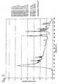
- a spectrum of a used Xe flashlampis shown with luminous plastic film, wherein the discharge tube consists of quartz glass.
- the phosphor filmis a silicone elastomer doped with inorganic phosphors which preferentially emit in the blue spectral region of 400-450 nm.
- the luminous-substance filmvirtually cuts off the UV range between 280-400 nm and transforms it into the visible blue range of 400-450 nm.
- the energy in the range below 400 nmis less than 4.5% of the total optical power
- the UV radiationis almost exclusively in the range of 340-400 nm and in particular in the range between 370-400 nm.
- ICNIRPInternational Commission on Non-Ionizing Radiation Protection Association Guidelines on the limits of exposure to ultraviolet radiation of wavelengths between 180 nm and 400 nm ", Health Physics 49: 331-340, 1985 or " Proposed change to the IPRA 1985 guidelines on exposure to ultraviolet radiation "Health Physics 56: 971-972, 1989 directed.
- the optical energy in the wavelength interval between 400-500 nmis 43.6% and in the wavelength interval between 400-450 nm 28.2% of the optical Overall performance.
- the measurementwas carried out with a calibrated CDI spectrometer and 100 ⁇ m UV fiber.
- the Xe flash lampis clocked at a frequency of 0.01-100 Hz, but the effective pulse lengths are between 10 ⁇ s and 1 ms.
- the energy of the individual pulsesis in the range of 0.3 to 0.8 J / cm 2.
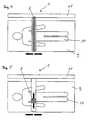
- the irradiation arrangement 1comprises a patient resting device 9, above which the radiation source 2 is arranged.
- the radiation source 2is again surrounded by a paraboloid, ellipsoid or half-cylinder reflector 3.
- the radiation source 2is pivotable together with the reflector 3 by means of a pivoting device, not shown, by the angle ⁇ from the vertical position to the patient resting device 9 to the left and at night.
- a pivoting devicenot shown, by the angle ⁇ from the vertical position to the patient resting device 9 to the left and at night.
- the radiation sourcecan be pulsed again or operated in cw mode.
- the patient resting device 9can also be pivoted.
- the irradiation source 2is in this case linear or strip-shaped irradiation source 2 is formed and arranged above the patient resting device 9 on a carrier 11 in the direction of arrow movable.
- the radiation source 2can be operated in pulse or cw mode. This scan movement in the direction of the arrow also achieves temporal light modulation for each individual body part.
- the one-dimensional scan movementmay turn off Figure 4 also be replaced by a two-dimensional scan movement.
- the planar irradiation source 2additionally transversely to the patient 10 movable.
- the necessity of a planar irradiation sourceshould be determined by the 6a-c be explained in more detail.
- the 6ais shown in cross section, which power densities are encountered in which depth of penetration, when the light output is irradiated with a beam diameter of 20 mm. As can be seen, the power density at 15 mm depth is still 0.1 kW / cm 2 .
- Figure 6bthe conditions are shown when the same total power is coupled into the tissue over a beam diameter of 1 mm. If a square irradiation area is assumed, the power density has quadrupled accordingly.
- the spectral dependence of the penetration depth (1 / e drop)is shown.
- the penetration depthincreases steadily from 400 nm to 900 nm, so that it is advantageous, especially in the treatment of deeper cells, to increase the green and red regions of the emitted spectrum at the expense of the blue fraction, even if the absorption of the porphyrins is opposite the blue part is worse.
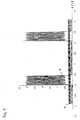
- FIG 8ais a preferred embodiment of an irradiation therapy with a pulsatile radiation source with an irradiation peak of 5 kW / cm 2 shown. In this case, a sequence of pulses or lightning is emitted.
- the individual pulsehas an effective pulse length t1 between 100-2000 ⁇ s, followed by a pulse-off time t2 between 10ms-1000s.
- the effective pulse length t1is preferably between 100-500 .mu.s and the pulse off-time t2 between 100 ms-4 s.
- the number of pulsesis preferably between 10 and 10,000, more preferably between 100 and 1000.
- the total pulse repetition time t3is given correspondingly (t1 + t2) multiplied by the number of pulses.
- This first pulse sequenceis followed by a time t4 in which irradiation is not carried out, so that oxygen can diffuse and the tissue can cool down at the same time, which prevents necrosis formation.
- the time t4is preferably chosen between 1 min and 100 min, the longer times being particularly preferred. Subsequently, a pulse train with the pulse repetition time t3 is generated again. This is followed by another time t4.
- the total irradiation time t5is chosen between a few minutes and 2 hours depending on the severity of the disease. After a long break of several hours or 1-3 days, the entire process is repeated. The internal or external addition of additional dye molecules is omitted altogether, so that the method described is not a PDT.
- the conditionswill be explained in more detail in a concrete example for the treatment of allergic contact eczema.
- two cycles of irradiationare performed per day, with t3 and t4 are each selected to 5 minutes, so that there is a total treatment time of 15 minutes per day.
- the pulse frequencyis 0.5 Hz, so that 150 pulses are applied in a period t3.
- the effective pulse length t1is 100 ⁇ s with a rise time of approx. 10 ⁇ s.
- the pulse off time t2is about 2s.
- the irradiation peak of the pulsesis 0.5 kW / cm 2 , the energy density per pulse depending on the slope steepness is between 0.4-0.5 J / cm 2 .
- the applied energy density per dayis 120-150 J / cm 2 .
- the total energy densityis 240-300 J / cm 2 , with the treatment preferably lasting 4-8 weeks.
- the described radiation therapywas also performed at a frequency of 0.05 Hz, maintaining the values for t1, t3 and t4 as well as the irradiation peak. Due to the tenfold increase in t2, the applied energy density per treatment cycle and the averaged cw performance decrease by a factor of ten, with treatment outcome results comparable. This is probably due to the very slow diffusion of oxygen, so that no additional increase in the energy density in equal times hardly causes any additional therapeutic effect without additional oxygen supply.
- the 8Bis the irradiation cycle with an irradiation arrangement according to Figure 4 shown, wherein the irradiation source is operated in CW operation.
- the irradiation peakis at 5 W / cm 2 , ie considerably lower than in pulsed operation according to Figure 8a .
- the time t1corresponds to the time that irradiates the irradiation source due to their areal radiation a particular area during the scanning process and is preferably between 0.1 and 0.5 s.
- the time t2is the time of a complete scan minus the time t1. During this time, oxygen can re-diffuse and cool the tissue.
- t2is between 1 and 300 seconds, preferably between 2-20 seconds.
- the combination between the scanning movementis shown with pulses, wherein the irradiation peaks between 250 and 500 W / cm 2 .
- the irradiation sourcepasses over a certain area, preferably 5 pulses are generated, wherein the first and the last pulse reach the area only partially due to the movement.
- the effective pulse lengthis preferably chosen to be 100 ⁇ s and the radiation source clocked at 25 Hz, so that t2 results in 40 ms for an irradiation time t3 of 0.2 s.
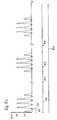
- FIG 9is the relative irradiance of a 1000 W mercury iodide lamp in cw normal operation at 1000 W (curve a) and in the pulse overload operation (curve b) shown, the average cw power is 1500 W in pulsed mode.
- the spectral energy density of such a gallium-doped mercury-iodide lamp rated at 1000 Wis shown when the input power is varied.
- the curve a)represents the energy density in cw normal operation at 1000 W.
- the curve b)represents the spectral energy density at underload of 100 W and the curve c) represents the energy density at 10 kW input power.
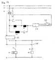
- FIG. 12a first circuit arrangement for operating a gallium-doped mercury iodide lamp for pulse overload operation is shown.
- the circuitcomprises a gallium-doped mercury iodide lamp 30, a Ignition rod 31, a current zero-crossing detector 32, a pulse generator 33, a first relay K1 and a second relay K2, and a starter switch S1 and a pulse switch 34.
- the two relays K1 and K2are both with a neutral N and a first phase V1 connected to a three-phase network.
- the gallium-doped mercury iodide lamp 30is connected via an auxiliary contact of the starter switch S1 with a second phase V2 of the three-phase network.
- the first phase V1is connected via the current-zero passage detector 32 via a coil arrangement with the ignition rod 31.
- the coils L1 and L2are connected in series. Parallel to this series connection, a third coil L3 is connected to a second relay K2 associated contact K2. Parallel to the first coil L1, a first associated contact K1.1 of the first relay K1 is connected. Between the second relay K2 and the pulse switch 34, a second associated contact K1.2 of the first relay K1 is connected.
- the starter switch S1is closed, which also close the two associated auxiliary contacts. This closes the contact K1.1 and the contact K1.2 opens or remains open.
- the first phase V1 of the three-phase networkis connected to the ignition rod 31 via the coil L2, the coil L2 acting as a series choke. This switching state is maintained until the gallium-doped mercury iodide lamp 30 has reached its normal operating conditions.
- the relay K1drops, which is designed for example as Einschaltwischer. The drop from the relay K1 causes an opening of the contact K1.1 and a closing of the contact K1.2.
- the relay K2is activated and at the same time the coil L1 connected in series with the coil L2, wherein the coil L1 acts as a simmer coil. Since the pulse switch 34 is still open, the contact K2 still remains open. In this state, the gallium-doped mercury iodide lamp 30 runs in a simmer.
- the current zero crossing detector 32now detects a zero crossing of the Current of the first phase V1 of the three-phase system and this signals the pulse generator 33. This switches the pulse switch 34, so that the relay K2 is energized and the contact K2 is closed.
- the coil L3is connected in parallel and the total inductance decreases. whereby the ignition rod 31 receives an overload pulse.
- the pulse generator 33opens the pulse switch 34.
- the contact K2is opened and the gallium-doped mercury iodide lamp 30 is operated again in the simmer through the series connection of the coils L1 and L2 until the next pulse is triggered by the pulse generator 33.
Landscapes
- Health & Medical Sciences (AREA)
- Biomedical Technology (AREA)
- Life Sciences & Earth Sciences (AREA)
- Engineering & Computer Science (AREA)
- Animal Behavior & Ethology (AREA)
- Veterinary Medicine (AREA)
- Nuclear Medicine, Radiotherapy & Molecular Imaging (AREA)
- Radiology & Medical Imaging (AREA)
- Biophysics (AREA)
- General Health & Medical Sciences (AREA)
- Public Health (AREA)
- Pathology (AREA)
- Radiation-Therapy Devices (AREA)
- Cosmetics (AREA)
- Glass Compositions (AREA)
- Treatments Of Macromolecular Shaped Articles (AREA)
- External Artificial Organs (AREA)
- Medicines Containing Plant Substances (AREA)
- Pharmaceuticals Containing Other Organic And Inorganic Compounds (AREA)
Abstract
Description
Translated fromGermanDie Erfindung betrifft eine Bestrahlungsanordnung für therapeutische Zwecke, insbesondere zur akuten oder chronischen Behandlung von ganz oder teilweise zellvermittelten Entzündungen der Haut, der Bindegewebe und der inneren Organe, viralen und anderen infektösen Erkrankungen wie HIV oder Prioneninfektionen, Pilzinfektionen der Haut und der Schleimhäute, bakteriellen Erkrankungen der Haut und der Schleimhäute sowie Hand- und Analekzemen.The invention relates to an irradiation arrangement for therapeutic purposes, in particular for the acute or chronic treatment of wholly or partially cell-mediated inflammation of the skin, connective tissue and internal organs, viral and other infectious diseases such as HIV or prion infections, fungal infections of the skin and mucous membranes, bacterial diseases the skin and mucous membranes as well as hand and anal eczema.
Therapeutische Bestrahlungsanordnungen sind insbesondere im Bereich der Phototherapie von Hauterkrankungen seit langem bekannt. Je nach Anwendungsgebiet wird dabei ein Patient im Wellenlängenbereich von 315-1500 nm bestrahlt. Insbesondere der Wellenlängenbereich zwischen 315-340 nm (UV-A2) kann nachweislich zu einem erhöhten Krebsrisiko führen, so daß insbesondere bei der Behandlung von atopischen Ekzemen die UV-A1-Therapie (340-400 nm) zur Anwendung kommt.Therapeutic irradiation arrangements have been known for a long time, in particular in the field of phototherapy of skin diseases. Depending on the field of application, a patient is irradiated in the wavelength range of 315-1500 nm. In particular, the wavelength range between 315-340 nm (UV-A2) can demonstrably lead to an increased risk of cancer, so that in particular in the treatment of atopic eczema UV-A1 therapy (340-400 nm) is used.
Die Chemo-Phototherapie als Oberbegriff umfaßt allgemein die Verwendung von optischer Strahlung zur Erzielung von therapeutischen Effekten. Ein Untergebiet der Chemo-Phototherapie ist die sogenannte photodynamische Therapie PDT. Zwei Hauptanwendungsgebiete der PDT sind die Krebsbehandlung und die Behandlung von ganz oder teilweise zellvermittelten Hautentzündungen. Gemeinsames Merkmal der PDT ist die Erzeugung von reaktiven Sauerstoff-Spezies. Hierzu regt die optische Strahlung inner- oder äußerlich verabreichte Farbstoffmoleküle an, die dann in einen angeregten Zustand überführt werden. Durch Wechselwirkung mit vorhandenen Sauerstoffmolekülen werden durch Energieübertragung reaktive Sauerstoff-Spezies gebildet, die dann die Zelle schädigen oder gar zerstören.Chemo-phototherapy as a generic term generally includes the use of optical radiation to achieve therapeutic effects. A subarea of chemo-phototherapy is the so-called photodynamic therapy PDT. Two main areas of application of PDT are the treatment of cancer and the treatment of wholly or partially cell-mediated dermatitis. A common feature of PDT is the generation of reactive oxygen species. For this purpose, the optical radiation excites intra- or externally administered dye molecules, which are then converted into an excited state. Through interaction with existing oxygen molecules, reactive oxygen species are formed by energy transfer, which then damage or even destroy the cell.
Bei der Krebstherapie mit PDT, wo die Tumorzellen zerstört werden sollen, sind zwei Anwendungsgebiete zu unterscheiden. Der Hauptanwendungsfall ist die Tumorbehandlung innerer Organe. Hierzu wird endoskopisch über eine Glasfaser die optische Strahlung eines Laser zu dem Tumor geleitet und dieser punktuell bestrahlt. Des weiteren werden dem Patienten Photosensibilisatoren gespritzt. Dabei tritt das Problem auf, daß das Tumorgewebe erheblich schlechter durchblutet ist, so daß auch der Sauerstoffgehalt sehr niedrig ist, was aber auch die Umwandlung in reaktive Sauerstoff-Spezies begrenzt. Daher ist es bei der Tumorbehandlung innerer Organe mit PDT bekannt, dem Patienten inspiratorisch erhöht Sauerstoff zuzuführen, so daß der Sauerstoffgehalt im Tumorgewebe erhöht wird und vermehrt reaktive Sauerstoff-Spezies gebildet werden können. Aufgrund des erhöhten Sauerstoffverbrauches ist es bekannt, die Bestrahlungsquelle im Pulsbetrieb zu betreiben, so daß in den Pulspausen Sauerstoff nachdiffundieren kann. Das zweite Anwendungsgebiet in der Krebstherapie mit PDT ist die Behandlung von äußeren Tumoren wie insbesondere Hautkrebs, wo aufgrund des vorhandenen Sauerstoffs in der Umgebung auf eine zusätzliche Sauerstoffzugabe verzichtet wird.In cancer therapy with PDT, where the tumor cells are to be destroyed, two areas of application should be distinguished. The main application is the tumor treatment of internal organs. For this purpose, the optical radiation of a laser is guided endoscopically via a glass fiber to the tumor and this irradiated punctually. Furthermore, the patient becomes photosensitizers injected. The problem arises that the tumor tissue is much less well supplied with blood, so that the oxygen content is very low, but also limits the conversion into reactive oxygen species. Therefore, in the tumor treatment of internal organs with PDT, it is known to inspiratively increase oxygen supply to the patient, so that the oxygen content in the tumor tissue is increased and more reactive oxygen species can be formed. Due to the increased oxygen consumption, it is known to operate the irradiation source in pulsed mode, so that oxygen can diffuse in the pulse pauses. The second area of application in the treatment of cancer with PDT is the treatment of external tumors such as, in particular, skin cancer, where due to the presence of oxygen in the environment, an additional addition of oxygen is dispensed with.
Bei der Behandlung von ganz oder teilweise zellvermittelten Hautentzündungen handelt es sich im Gegensatz zu Tumoren stets um großflächige Entzündungen, so daß hier flächenhafte Strahlungsquellen zur Anwendung kommen, die Behandlungsflächen von beispielsweise 5 cm2 bis 2 m2 simultan bestrahlen. Ein weiterer Unterschied zu den Tumoren ist die erhöhte Durchblutung von Entzündungen, die bereits äußerlich durch die vorhandene Rötung im Entzündungsbereich gut erkennbar ist. Des weiteren findet keine exogene Sensibilisatorapplikation statt, so daß selbst unter der Annahme einer phototherapeutisch induzierten Beteiligung von Singulett-Sauerstoff, z.B. über die photodynamische Wirkung endogener Porphyrine, davon auszugehen ist, daß selbst bei einer erheblichen Verminderung der Sauerstoffkonzentration in der Haut es nur zu einer unwesentlichen Verminderung der Triplet-Effizienz kommt. Darüber hinaus liegt die maximale Konzentration endogener Photosensibilisatoren um mehrere Größenordnungen unter der Konzentration, die nach topischer und/oder systemischer Applikation erreichbar ist. Die erwähnte gute Hautdurchblutung in Verbindung mit der geringen Sensibilisatorkonzentration führte dazu, daß es bisher nicht zu einer synchronen Foto/Sauerstofftherapie bei den zellvermittelten Erkrankungen gekommen ist.In contrast to tumors, the treatment of wholly or partially cell-mediated skin inflammations always involves large-area inflammations, so that areal radiation sources are used here, which irradiate treatment areas of, for example, 5 cm2 to 2 m2 simultaneously. Another difference to the tumors is the increased blood flow of inflammation, which is already well visible externally by the existing redness in the inflammatory area. Furthermore, no exogenous sensitizer application takes place, so that even assuming a phototherapeutically induced involvement of singlet oxygen, eg via the photodynamic action of endogenous porphyrins, it can be assumed that even with a significant reduction in the oxygen concentration in the skin, only one insignificant reduction in triplet efficiency. In addition, the maximum concentration of endogenous photosensitizers is several orders of magnitude below the concentration attainable after topical and / or systemic application. The above-mentioned good skin perfusion in combination with the low sensitizer concentration has led to the fact that it has not been a synchronous photo / oxygen therapy in the cell-mediated diseases has come.
Das überwiegend in der Behandlung von ganz oder teilweise zellvermittelten Hauterkrankungen eingesetzte Verfahren der PDT ist die hochdosierte UV-A1-Therapie im Wellenlängenbereich von 340-400 nm. Dabei ist zum einen die Abgabe hoher Dosen von beispielsweise 130 J/cm2 und zum anderen die Bestrahlungsstärke von mehr als 60 mW/cm2 erforderlich, um ausreichende therapeutische Effekte zu bewirken. Trotzdem bleibt bei ca. 20 - 30 % der behandelten Patienten die UV-A1-Therapie wirkungslos.The predominantly used in the treatment of whole or partial cell-mediated skin diseases PDT method is the high-dose UV-A1 therapy in the wavelength range of 340-400 nm. It is on the one hand the delivery of high doses of, for example, 130 J / cm2 and the other Irradiance of more than 60 mW / cm2 is required to produce sufficient therapeutic effects. Nevertheless, in about 20 - 30% of the treated patients, the UV-A1 therapy is ineffective.
Es ist weiter bekannt, Akne, eine aufgrund von Bakterienwachstum in verstopften Follikeln talgdrüsenreicher Hautbezirke mit Verhornungsstörungen hervorgerufene Hauterkrankung, mit blauem Licht im Bereich von 400 - 440 nm ohne wesentliche UVA-Anteile zu behandeln, wobei die Erfolge beschränkt blieben. Hierzu sei auf den Fachartikel "
Aus der
Aus der
Aus der
Aus der
Aus der
Aus der
Der Erfindung liegt daher das technische Problem zugrunde, eine Bestrahlungsanordnung zur Behandlung von akuten und chronischen ganz oder teilweise zellvermittelten Entzündungen der Haut und der inneren Organe, viralen und anderen infektiösen Erkrankungen wie HIV oder Prionenerkrankungen, Pilzinfektionen der Haut und der Schleimhäute, bakteriellen Erkrankungen der Haut und der Schleimhäute sowie Hand- und Analekzemen zu schaffen, die gegenüber den bekannten Bestrahlungsanordnungen eine verbesserte therapeutische Wirksamkeit aufweisen.The invention is therefore based on the technical problem of an irradiation arrangement for the treatment of acute and chronic wholly or partially cell-mediated inflammation of the skin and internal organs, viral and other infectious diseases such as HIV or prion diseases, fungal infections of the skin and mucous membranes, bacterial diseases of the skin and the mucous membranes as well as hand and anal eczema, which have improved therapeutic efficacy compared to the known irradiation arrangements.
Die Lösung des technischen Problems ergibt sich durch den Gegenstand mit den Merkmalen des Patentanspruchs 1. Weitere vorteilhafte Ausgestaltungen der Erfindung ergeben sich aus den Unteransprüchen.The solution of the technical problem results from the subject matter with the features of
Hierzu umfaßt die Bestrahlungsanordnung mindestens eine Bestrahlungsquelle zur flächenhaften Bestrahlung einer Behandlungsfläche, wobei die Wellenlänge der emittierten Strahlung auf der Behandlungsfläche größer als 400 nm ist und mindestens einen Spektralanteil im Wellenlängenintervall von 400-500 nm umfaßt und die Bestrahlungsanordnung Mittel zur Erzeugung von optischen Pulsen auf der Behandlungsfläche umfaßt, wobei die Bestrahlungsstärke pro Puls zwischen 0,5 W/cm2- 100 kW/cm2 ist, wobei die Energiedichte eines emittierten optischen Pulses zwischen 0,3-0,8 J/cm2 liegt. Die Angaben für die Bestrahlungsstärke und die Energiedichte beziehen sich auf die zu bestrahlende Fläche, wenn die Bestrahlungsanordnung direkt auf die Oberfläche aufgesetzt wird. Dabei wird unter flächenhaft eine Bestrahlungsfläche von größer 0,1 cm2 verstanden. Die Aussage größer 400 nm bedeutet dabei, daß weniger als 7 % der optischen Gesamtleistung im UV-Bereich emittiert werden, wohingegen im Wellenlängenintervall von 400-500 nm mindestens 30 % der optischen Leistung emittiert werden. Die Anteile im UVC- und UVB-Bereich sind dabei vernachlässigbar klein im Bereich unter 0,1 % der Gesamtleistung, sodass der gesamte verbleibende UV-Anteil im UVA1- und UVA2-Bereich liegt, wobei deren Verhältnis ca. 1/10 ist, d.h. der überwiegende Anteil der verbleibenden UV-Strahlung liegt im UVA1-Bereich zwischen 340-400 nm. Weiter vorzugsweise macht der UV-Anteil weniger als 3,5-5 % der optischen Gesamtleistung und der Bereich zwischen 400-500 nm mehr als 40 % der optischen Gesamtleistung aus.For this purpose, the irradiation arrangement comprises at least one irradiation source for the planar irradiation of a treatment surface, wherein the wavelength of the emitted radiation on the treatment surface is greater than 400 nm and at least a spectral component in the wavelength interval of 400-500 nm and the irradiation means comprises means for generating optical pulses on the Treatment area comprises, wherein the irradiance per pulse between 0.5 W / cm2 - 100 kW / cm2 , wherein the energy density of an emitted optical pulse between 0.3-0.8 J / cm2 . The data for the irradiance and the energy density refer to the surface to be irradiated when the irradiation arrangement is placed directly on the surface. In this case, the term "areal" refers to an irradiation area of greater than 0.1 cm2 . The statement greater than 400 nm means that less than 7% of the total optical power is emitted in the UV range, whereas at least 30% of the optical power is emitted in the wavelength interval of 400-500 nm. The proportions in the UVC and UVB range are negligibly small in the range below 0.1% of the total power, so that the total remaining UV component in the UVA1 and UVA2 range, wherein their ratio is about 1/10, ie the majority of the remaining UV radiation is in the UVA1 range between 340-400 nm. More preferably, the UV content makes up less than 3.5-5% of the total optical power and the range between 400-500 nm more than 40% of the total optical power.
Erfindungsgemäß wird dabei ausgenutzt, daß bei einer pulsförmigen Bestrahlung in den Zeiten hoher Leistungsdichte, entgegen den Ausführungen in der Literatur, die Bildung von Singulett-Sauerstoff um Größenordnungen gegenüber cw-Betrieb bei gleicher Energie erhöht wird. Ein weiterer Vorteil der extrem erhöhten Leistungsdichte ist, daß auch tiefer unter der Haut liegende Bereiche noch eine ausreichende Bestrahlungsstärke erhalten, da üblicherweise aufgrund der geringen Eindringtiefe des blauen Lichtes nur ein Bruchteil der cw-Leistung die tieferliegenden Bereiche erreicht. Zusätzlich hat pulsförmig applizierte Strahlungsenergie eine erheblich stärkere photobiologische Wirkung. Bei gleicher integraler Gesamtdosis von cw- und Pulseinstrahlung bliebe z.B. bei einer angenommenen cw-Bestrahlungsstärke von 70 mW/cm2 aufgrund der Wirkung körpereigener Antioxidatien, die z.B.60 mW/cm2 der eingestrahlten Leistung als konstanten Off-Set neutralisieren, nur 10 mW/cm2 für photobiologische Wirkungen verfügbar. Es ist unmittelbar einsichtig, daß die relative photobiologische Wirkungsverminderung durch diesen konstanten Off-Set durch gepulste Einstrahlung höchst effektiv vermindert werden kann. Bei Pulsleistungen im kW-Betrieb führt dieser Off-Set nicht mehr zu einer signifikanten Verminderung der Strahlungswirkung. Die mittlere Energiezufuhr wird dabei derart gewählt, daß die Nekroseschwelle für die Zellen vermieden wird und nur eine Apoptose der Zellen induziert wird. Ebenso wird die in der EP 0 565 331 B1 angestrebte Ablationsschwelle unterschritten. Eine Ablation, d.h. Gewebeverdampfung tritt immer dann auf, wenn eine Energie >2500 J/cm3 innerhalb einer Zeit im Gewebe deponiert wird, die nicht erlaubt, daß ein signifikanter Wärmeaustausch mit angrenzenden Schichten möglich ist. Aufgrund der zeitlichen Modulation durch die Pulserzeugung, wobei die Belichtungszeit unterhalb der thermischen Relaxationszeit der oberen Hautschicht liegt, kommt es zwar zu einer sehr starken Erwärmung der oberen Hautschicht, die jedoch sehr einfach abgeführt werden kann. Licht im Wellenlängenbereich 400-500 nm hat eine halbmaximale Eindringtiefe von ca. 200 µm. Die geschätzte thermische Relaxationszeit für eine Struktur mit einem Durchmesser von 200 µm beträgt ca. 20 ms. Dies bedeutet, daß bei einer Verweildauer des Lichtstrahls <20 ms lediglich die oberen Hautschichten erwärmt werden, ohne daß es zu einer Tiefendeposition der Energie kommt.According to the invention, use is made of the fact that in the case of pulsed irradiation in times of high power density, contrary to what is stated in the literature, the formation of singlet oxygen is increased by orders of magnitude compared to cw operation with the same energy. A further advantage of the extremely increased power density is that areas lying deeper under the skin still receive sufficient irradiance, since usually only a fraction of the cw power reaches the deeper areas due to the low penetration depth of the blue light. In addition, pulsed radiant energy has a much stronger photobiological effect. For the same integral total dose of cw and pulse radiation, for example, with an assumed cw irradiance of 70 mW / cm2 , only 10 mW / cm would remain due to the effect of the body's own antioxidants, which neutralize eg 60 mW / cm2 of the radiated power as a constant off-set2 available for photobiological effects. It is immediately apparent that the relative photobiological effect reduction by this constant off-set can be most effectively reduced by pulsed radiation. With pulse power in kW mode, this off-set no longer leads to a significant reduction in the radiation effect. The average energy input is chosen such that the necrosis threshold for the cells is avoided and only apoptosis of the cells is induced. Likewise, the ablation threshold desired in
Neben den beschriebenen Anwendungsgebieten ist die Bestrahlungsanordnung auch zur Wunddesinfektion nach Verbrennungen oder zur Behandlung bei venösen Geschwüren am Unterschenkel geeignet. Diese werden bisher mit UV-Licht behandelt, wobei es häufig zu einer kurzzeitgen Verbesserung kommt. Jedoch treten häufig Komplikationen bei der langfristigen Wundheilung auf. Die Ursache für die kurzzeitigen Erfolge liegt vermutlich in der keimtötenden Wirkung von UV-Licht, wohingegen die Komplikationen aufgrund irreparabler Zellschädigungen verursacht werden. Durch eine UV-freie, zeitlich modulierte Bestrahlung duch die optischen Pulse, bevorzugt im Spektralbereich von 400-500 nm, weiter bevorzugt im Bereich von 40-480 nm und noch weiter bevorzugt im Bereich 400-420 nm kommt es in allen Zellen zwar zunächst zu einer oxidativen Schädigung, die jedoch von Eukaryontenzellen wegen der dort vorhandenen FPG-Endonukleotidasen leicht reparabel ist. Prokaryonten wie Staphylokokken oder Streptokokken sind wegen Fehlens dieser Enzyme sehr viel empfindlicher auf eine derartige Schädigung und können somit selektiv abgetötet werden. Ebenso ist die Bestrahlungsanordnung auch zur Behandlung von Akne und Aknenarben geeignet. Hierbei kommt es durch die Aktivierung körpereigener kollagenabbauender Enzyme zu einer Verflachung der Narbe. Diese Wirkungen treten auch bei der Behandlung der Sklerodermie auf, wo mit Hilfe der Bestrahlungsanordnung eine wirksame Verminderung der vernarbten Kollagen Plaques erreichbar ist. Darüber hinaus wurde bei Patienten mit Sklerodermie eine ausgeprägte Wirkung der gepulsten Bestrahlung auf die zirkulierenden Lymphozyten beobachtet. Insbesondere kam es bereits nach fünf Bestrahlungen zu einer Abnahme von Kiler-Lymphozyten von 75%. Die Anzahl der zirkulierenden Lymphozyten nahm unter der Behandlung um ca. 25 % ab. Diese Befunde sind am ehesten dadurch erklärbar, daß die entzündungsaktivierten Lymphozyten über eine Änderung ihrer endogenen Farbstoffkonzentration für die durchgeführte Bestrahlung empfindlich genug waren, um eine Apoptose auszulösen.In addition to the described fields of application, the irradiation arrangement is also suitable for wound disinfection after burns or for the treatment of venous ulcers on the lower leg. These are so far treated with UV light, which often leads to a kurzzeitgen improvement. However, complications often occur in long-term wound healing. The cause of the short-term success is probably the germicidal effect of UV light, whereas the complications are caused by irreparable cell damage. UV-free, temporally modulated irradiation by the optical pulses, preferably in the spectral range of 400-500 nm, more preferably in the range of 40-480 nm and even more preferably in the range 400-420 nm, occurs in all cells, although initially oxidative damage, however, is easily reparable by eukaryotic cells because of the FPG endonucleotides present there. Prokaryotes such as staphylococci or streptococci are much more sensitive to such damage due to the lack of these enzymes and thus can be selectively killed. Likewise, the irradiation arrangement is also suitable for the treatment of acne and acne scars. In this case, activation of the body's own collagen-degrading enzymes leads to a flattening of the scar. These effects also occur in the treatment of scleroderma, where with the aid of the irradiation arrangement an effective reduction of the scarred collagen plaques can be achieved. In addition, in patients with scleroderma a pronounced effect of pulsed irradiation on the circulating lymphocytes. In particular, a decrease of Kiler lymphocytes of 75% already occurred after five irradiations. The number of circulating lymphocytes decreased by about 25% during treatment. These findings are most likely to be explained by the fact that the inflammation-activated lymphocytes were sensitive enough to initiate apoptosis by changing their endogenous dye concentration for the irradiation performed.
Die Pulse können entweder durch eine gepulste Bestrahlungsquelle und/oder durch eine Relativbewegung der Bestrahlungsquelle zu der zu behandelnden Fläche erzeugt werden.The pulses can be generated either by a pulsed irradiation source and / or by a relative movement of the irradiation source to the surface to be treated.
Vorzugsweise liegen die effektiven Pulslängen zwischen 1 µs und 500 ms. Dieser relativ breite Bereich kommt daher, daß die bevorzugten effektiven Pulslängen für gepulste Bestrahlungsquellen und relativ bewegte Bestrahlungsquellen in Form eines Scanners unterschiedlich sind. Dabei ist anzumerken, daß der Scanner bevorzugt zur Behandlung größflächiger Hauterkrankungen zur Anwendung kommt.The effective pulse lengths are preferably between 1 μs and 500 ms. This relatively wide range is due to the fact that the preferred effective pulse lengths for pulsed radiation sources and relatively moving radiation sources in the form of a scanner are different. It should be noted that the scanner is preferably used for the treatment of large-area skin diseases.
Bei den Blitzlampen liegen die effektiven Pulslängen vorzugsweise zwischen 1 µs und 50 ms, besonders bevorzugt zwischen 10 µs und 10 ms und weiter bevorzugt zwischen 100-600 µs, wobei die Pulsein- und auszeiten unsymmetrisch sind.In the case of flash lamps, the effective pulse lengths are preferably between 1 μs and 50 ms, more preferably between 10 μs and 10 ms and more preferably between 100-600 μs, the pulse on and off times being asymmetrical.
Bei einer Ausbildung als Scanner liegen die effektiven Pulslängen vorzugsweise zwischen 1 ms und 500 ms, weiter vorzugsweise zwischen 20-100 ms. Unter effektiver Pulslänge wird dabei die Zeit verstanden, die zwischen Erreichen von 50 % der maximalen Leistung bis zum Abfall auf 50% der maximalen Leistung liegt. Die im Verhältnis zur effektiven Pulslänge längeren Pulsauszeiten dienen dabei insbesondere der Nachdiffusion von Sauerstoff. Das Verhältnis Pulslänge und Pulsauszeit liegt dabei vorzugsweise beim Scanner zwischen 3 und 3000 und bei der Blitzlampe zwischen 100 und 100.000. Ein weiterer Effekt ist die thermische Abkühlung der bestrahlten Fläche während der Pulsauszeiten, so daß keine Nekrose auftritt.When designed as a scanner, the effective pulse lengths are preferably between 1 ms and 500 ms, more preferably between 20-100 ms. The term "effective pulse length" is understood to mean the time between 50% of the maximum power and the drop to 50% of the maximum power. The longer pulse time-outs in relation to the effective pulse length are used in particular for the post-diffusion of oxygen. The ratio pulse length and pulse off time is preferably between 3 and 3000 for the scanner and between 100 and 100 for the flash lamp 100,000. Another effect is the thermal cooling of the irradiated area during the pulse times, so that no necrosis occurs.
In einer weiteren bevorzugten Ausführungsform liegt die Frequenz, mit der die Bestrahlungsquelle gepulst wird, zwischen 0,01 - 100 Hz, weiter bevorzugt zwischen 0,05-50 Hz und noch bevorzugter zwischen 0,3-3 Hz, wobei bei höheren Frequenzen niedrigere effektive Pulslängen und kleinere Pulsenergien verwendet werden.In another preferred embodiment, the frequency at which the radiation source is pulsed is between 0.01-100 Hz, more preferably between 0.05-50 Hz, and even more preferably between 0.3-3 Hz, with lower effective ones at higher frequencies Pulse lengths and smaller pulse energies are used.
Um die Nachdiffusion von Sauerstoff und die thermische Abkühlung zu verbessern, wird vorzugsweise nach einer Pulsfolge von beispielsweise 100-500 Pulsen eine längere Dunkelphase von mehreren Sekunden bis Minuten eingelegt, bevor wieder erneut eine Pulsfolge erzeugt wird. Aufgrund der extrem langen Diffusionszeiten von Sauerstoff sind auch Anwendungen vorstellbar, wo nur jeweils ein Puls verabreicht wird und anschließend die Bestrahlungsanordnung wieder für eine längere Zeit abgeschaltet wird. Die Pausen können dabei im Bereich von einer bis mehreren Stunden liegen. Insbesondere zur Behandlung chronischer Erkrankungen kann dabei die Bestrahlungsanordnung beispielsweise in Form eines Gürtels, einer Bestrahlungsdecke oder eines Lichtbettes fest dem Patienten zugeordnet sein, der dann beispielsweise alle 5 Minuten einen optischen Puls erhält. Bei diesen langen Pausen sind thermische Probleme oder die Nachdiffusion von Sauerstoff vernachlässigbar.In order to improve the postdiffusion of oxygen and the thermal cooling, preferably after a pulse sequence of, for example, 100-500 pulses, a longer dark phase of several seconds to minutes is inserted, before again a pulse train is generated. Due to the extremely long diffusion times of oxygen, applications are conceivable where only one pulse is administered and then the irradiation arrangement is switched off again for a longer time. The breaks can be in the range of one to several hours. In particular for the treatment of chronic diseases, the irradiation arrangement, for example in the form of a belt, an irradiation ceiling or a bed of light, can be fixedly assigned to the patient, who then receives an optical pulse every 5 minutes, for example. During these long breaks, thermal problems or postdiffusion of oxygen are negligible.
Ebenso wie die effektiven Pulslängen davon abhängig sind, ob eine gepulste Bestrahlungsquelle oder eine relativ bewegte Bestrahlungsquelle verwendet wird, sind auch die bevorzugten Bestrahlungsstärken bzw. Leistungsdichten pro Puls unterschiedlich.As well as the effective pulse lengths depend on whether a pulsed radiation source or a relatively moving radiation source is used, the preferred irradiation strengths or power densities per pulse are different.
Bei Ausführungsformen mit gepulster Bestrahlungsquelle liegt die Bestrahlungsstärke pro Puls zwischen 1 W/cm2-100 kW/cm2, vorzugsweise zwischen 50 W/cm2-50 kW/cm2, weiter bevorzugt zwischen 500 W/cm2- 10 kw/cm2 und besonders bevorzugt zwischen 1kW/cm2-5 kW/cm2. Die Energiedichte pro Puls liegt dabei zwischen 50 mJ/cm2-10J/cm2, vorzugsweise zwischen 100 mJ/cm2-5J/cm2 und besonders bevorzugt zwischen 300 mJ/cm2-3J/cm2.In embodiments with a pulsed radiation source, the irradiance per pulse is between 1 W / cm2 -100 kW / cm2 , preferably between 50 W / cm2 -50 kW / cm2 , more preferably between 500 W / cm2 - 10 kw / cm2 and more preferably between 1kW / cm2 -5 kW / cm2 . The energy density per pulse is between 50 mJ / cm2 -10J / cm2 , preferably between 100 mJ / cm2 -5J / cm2 and particularly preferably between 300 mJ / cm2 -3J / cm2 .
Bei Ausführungsformen mit einem Scanner, wobei zusätzlich die Bestrahlungsquelle auch gepulst sein kann, liegen die Bestrahlungsstärken pro Puls zwischen 500 mW/cm2-500W/cm2, vorzugsweise zwischen 1-300 W/cm2 und besonders bevorzugt zwischen 50-200 W/cm2.In embodiments with a scanner, wherein in addition the radiation source may also be pulsed, the irradiation intensities per pulse are between 500 mW / cm2 -500 W / cm2 , preferably between 1-300 W / cm2 and particularly preferably between 50-200 W / cm2 .
Die über die volle Periode gemittelte cw-Bestrahlungsstärke eines optischen Pulses liegt vorzugsweise zwischen 1 mW/cm2 und 10 W/cm2, weiter bevorzugt zwischen 5-2000 mW/cm2 und besonders bevorzugt zwischen 8-800 mW/cm2. Unter gemittelter cw-Bestrahlungsstärke wird dabei der Wert verstanden, der sich ergeben würde, wenn dieBestrahlungsstärke eines Pulses gleichmäßig über die volle Periode aufgeteilt werden würde.The cw irradiance of an optical pulse averaged over the full period is preferably between 1 mW / cm2 and 10 W / cm2 , more preferably between 5-2000 mW / cm2 and particularly preferably between 8-800 mW / cm2 . Mean averaged cw irradiance is understood to mean the value that would result if the irradiance of a pulse were divided equally over the full period.
In einer weiteren bevorzugten Ausführungsform ist die Bestrahlungsquelle als Xe-Blitzlampe ausgebildet, der eine Einrichtung zur Unterdrückung und/oder zur Transformierung der unerwünschten Spektralanteile in den gewünschten Spektralbereich zugeordnet ist. Diese handelsüblichen Xe-Blitzlampen sind sehr preiswert und emittieren mit ausreichender Leistungsdichte im gewünschten Spektralbereich zwischen 400 - 500 nm. Hierzu wird beispielsweise auf die
Eine weitere mögliche Bestrahlungsquelle ist eine im Überlastbereich gepulste galliumjodid-Quecksilberentladungslampe. Dabei wird unter Überlast verstanden, wenn der maximale Entladungsstrom mindestens 3-1000 fach über dem Lampennennstrom liegt, wobei der Impulsentladungsstrom vorzugsweise zwischen 15-1500 A/cm2 Querschnittsfläche des Entladungsgefäßes liegt. Handelsübliche cw-betriebene metalldampfdotierte Quecksilberhalogenid-Lampen sind beispielsweise in der
Aus der
Deshalb wurden diese bisher nicht im Überlastbetrieb gefahren, da es aus plasmaphysikalischen Untersuchungen bekannt war, dass schmalbandige Emissionsspektren nur bei vergleichsweise niedriger Anregungsenergie darstellbar sind. Im Überlastbetrieb steigt der Dampfdruck im Entladungslasma so stark an, dass die Linienemission vom Umgebungsplasma absorbiert wird und es paradoxerweise zu einer erheblichen Schwächung oder sogar einer kompletten Löschung der Resonanzlinienemission bei hohen Entladungsdrücken kommt. Als Beispiele seien die Quecksilberresonanzlinie bei 254 nm, die Natriumresonanzlinie bei 488 nm und die Indiumresonanzlinie bei 450 nm genannt, wo es schon bei mäßiger Überlast zu einem Verlust der Spektralintensität kommt.Therefore, these have not been driven in overload mode, since it is off Plasma-physical investigations was known that narrow-band emission spectra can be displayed only at comparatively low excitation energy. In overload operation, the vapor pressure in the discharge plasma increases so much that the line emission is absorbed by the ambient plasma and, paradoxically, there is a significant weakening or even complete quenching of the resonance line emission at high discharge pressures. Examples are the mercury resonance line at 254 nm, the sodium resonance line at 488 nm and the indium resonance line at 450 nm, where a loss of spectral intensity occurs even under moderate overload.
Überraschend wurde jedoch entdeckt, daß galliumdotierte Quecksilberjodid-Mittel- bzw. Hochdrucklampen selbst bei einer 100-1000 fachen Überlast weder eine Verbreiterung oder gar Inversion der Galliumresonanzlinien bei 403 und 417 nm zeigen. Eine unter Nennlast mit einem Entladungsstrom von 1,5 A/cm2 Querschnittsfläche des Entladungsgefäßes betriebene galliumjodiddotierte Quecksilberentladungslampe konnte im Pulsbetrieb bis auf 1000 A/cm2 Querschnittsfläche des Entladungsgefäßes betrieben werden, ohne daß es zu einer Abschwächung oder Frequenzinversion der Galliumresonanzlinien kam. Eine mögliche Erklärung hierfür ist, daß das metallische Gallium einen Siedepunkt von ca. 2200°C aufweist, so daß der diesbezügliche Galliumdampfdruck auch unter Impulsbedingungen vermutlich zu vernachlässigen ist. Im Plasma kommt es zu einer Zersetzung des Quecksilberiodids in Quecksilber und Jod. Das Jod verbindet sich unter den Entladungsbedingungen mit dem Gallium in Form der instabilen Verbindung Gal3. Galliumiodid zeigt eine starke Dampfdruckzunahme bereits bei niedrigen Temperaturen. Die fehlende Inversion der Galliumresonanzlinie wäre nun dadurch erklärbar, dass das Galliumiodid sich nur bis zu einem bestimmten Druck stabil verhält und es bei einer Druckzunahme zu einem massiven, vermutlich kinetisch außerordentlich schnellem Zerfall der Verbindung kommt. In der Folge stellt sich trotz zunehmender hoher Temperaturen während des Impulses ein relativ konstanter Galliumdampfdruck ein. Somit trägt das kondensierte Gallium nicht zur Entladung bzw. zur möglichen Selbstabsorption bei. Der unerwartet aufgetretene Effekt könnte deshalb mit einer paradoxen Konstanz des Galliumdampfdrucks über einen Temperaturbereich von 200 bis fast 2200° C zusammenhängen. Quecksilberjodid zerfällt bereits früh in Quecksilber und Jod, so dass das Jod für eine Galliumverbindung zur Verfügung steht und der Quecksilberdampfdruck mit der eingespeisten Energie stark zunimmt. Auf diese Weise steht der Galliumresonanz entsprechend dem Wirkungsquerschnitt des entsprechenden Galliumplasmas eine proportional zur eingespeisten Energie zunehmende Anregung durch die kurzwelligen Quecksilberelektronenübergänge zur Verfügung. Diese Energie kann wegen der relativen Konstanz des Galliumdampfdruckes fast in der gesamten Höhe als Resonanzlinienspektrum emittiert werden.Surprisingly, however, it has been discovered that gallium doped mercury iodide medium and high pressure lamps, respectively, do not show broadening or even inversion of gallium resonance lines at 403 and 417 nm, even at a 100-1000 fold overload. A gallium iodide-doped mercury discharge lamp operated under rated load with a discharge current of 1.5 A / cm2 cross-sectional area of the discharge vessel could be operated in the pulse mode up to 1000 A / cm2 cross-sectional area of the discharge vessel, without causing attenuation or frequency inversion of the Galliumresonanzlinien. A possible explanation for this is that the metallic gallium has a boiling point of about 2200 ° C, so that the relevant gallium vapor pressure is probably negligible even under pulse conditions. In plasma, the mercury iodide decomposes into mercury and iodine. The iodine combines under the discharge conditions with the gallium in the form of the unstable compound Gal3 . Gallium iodide shows a strong increase in vapor pressure even at low temperatures. The lack of inversion of the gallium resonance line could now be explained by the fact that the gallium iodide behaves stably only up to a certain pressure and that a pressure increase leads to a massive, presumably kinetically extremely rapid decomposition of the compound. As a result, despite increasing high temperatures during the pulse, a relatively constant gallium vapor pressure sets in. Thus, that contributes Condensed gallium does not contribute to the discharge or the possible self-absorption. The unexpected effect could therefore be related to a paradoxical constancy of gallium vapor pressure over a temperature range of 200 to almost 2200 ° C. Mercury iodide decomposes early into mercury and iodine, so that the iodine is available for a gallium compound and the mercury vapor pressure increases sharply with the energy supplied. In this way, the gallium resonance corresponding to the cross section of the corresponding gallium plasma is an increasing excitation by the short-wave mercury electron transitions in proportion to the energy fed. Due to the relative constancy of the gallium vapor pressure, this energy can be emitted almost in its entire height as a resonance line spectrum.
Während des Überlastbetriebes kommt es zu einer kurzzeitigen Überhitzung, insbesondere der Wolframwendeln, die jedoch bei einer Zunahme der Temperatur entsprechend dem Planckschen Gesetz erheblich mehr Wärme abstrahlen können. Daher kann eine modulierte Lampe mit einer erhöhten Grundlast betrieben werden, da die Abgabe der zugeführten Energie nur aufgrund der Temperaturerhöhung erheblich effizienter ist als bei einer Lampe im Normalbetrieb. Dabei hat sich herausgestellt, dass sich eine 1 kW Lampe mit einer Dauerlast von ca. 2-20 kW betreiben läßt. Bei spektralen Messungen hat sich gezeigt, daß bei einer 1000 W cw-Betrieb galliumdotierten Quecksilberiodid-Lampe ca. 400 mW/m2 im Spektralbereich zwischen 400-440 nm die Haut treffen. Diese Bestrahlungsstärke läßt sich im Simmerbetrieb auf eine gemittelte Bestrahlungsstärke von ca.2-4 mW/cm2 vermindern, wobei unter Impulslast die Bestrahlungsstärke kurzzeitig um bis zu vier bis fünf Größenordnungen angehoben wird, so daß Bestrahlungsstärken zwischen 2 bis 400 W/cm2 auf die Haut treffen. Das Verhältnis der Pulslängen liegt vorzugsweise im Bereich zwischen 3 und 300. Diese einfache Impulslichtquelle im Spektralbereich von 320-540 nm ist auch für andere technische Anwendungen verwendbar, wie beispielsweise drucktechnische Anwendungen, Oberflächenversiegelungen, Rohrsanierung mit lichthärtenden Schläuchen, Kunststoffhärtung im Bereich der DVD-Produktion sowie die Beschleunigung anderer photochemischer Reaktionen, die über Radikalmechanismen einer Photoabsorption im UV-Blaubereich des Spektrums beeinflußt werden.During overload operation, overheating occurs for a short time, in particular the tungsten filaments, which, however, can radiate considerably more heat as the temperature increases according to Planck's law. Therefore, a modulated lamp can be operated with an increased base load, since the delivery of the supplied energy is only much more efficient due to the increase in temperature than a lamp in normal operation. It has been found that a 1 kW lamp can be operated with a continuous load of about 2-20 kW. In spectral measurements it has been shown that in a 1000 W cw operation gallium-doped mercury iodide lamp about 400 mW / m2 in the spectral range between 400-440 nm hit the skin. This irradiance can be reduced in Simmerbetrieb to an average irradiance of about 2-4 mW / cm2 , under momentum load, the irradiance is briefly increased by up to four to five orders of magnitude so that irradiances between 2 to 400 W / cm2 on to hit the skin. The ratio of the pulse lengths is preferably in the range between 3 and 300. This simple pulsed light source in the spectral range of 320-540 nm is also suitable for other technical applications, such as printing applications, surface sealing, pipe renovation with light-curing tubing, Plastic curing in the field of DVD production and the acceleration of other photochemical reactions that are influenced by radical mechanisms of photoabsorption in the UV-blue region of the spectrum.
Das Verhältnis Gallium bzw. Galliumadditiv zu Quecksilber sollte vorzugsweise zwischen 1:10 bis 1:100 sein. Im Leistungsbereich von 400 W kommt vorzugsweise ein Mischungsverhältnis von 1-5 mg Galliumiodid auf 44 mg Quecksilber zur Anwendung.The ratio of gallium or gallium additive to mercury should preferably be between 1:10 and 1: 100. In the power range of 400 W, a mixing ratio of 1-5 mg gallium iodide to 44 mg mercury is preferably used.
Eine andere typische Lampe besteht aus einem zylindrischen Quarzrohr mit Durchmesser 13,5 mm und einem Volumen des Entladungsgefäßes von 20 cm3. Der Elektrodenabstand beträgt ca.14 cm. Eine derartige Lampe wird mit 20 mg Hg, 3 mg Quecksilberiodid, 1 mg Gallium und Argon mit einem Druck von 3,57 mmHg befüllt.Another typical lamp consists of a cylindrical quartz tube with a diameter of 13.5 mm and a volume of the discharge vessel of 20 cm3 . The electrode distance is about 14 cm. Such a lamp is filled with 20 mg Hg, 3 mg mercury iodide, 1 mg gallium and argon at a pressure of 3.57 mmHg.
Die UV-Anteile können jedoch auch in den gewünschten Spektralbereich transformiert werden. Dabei haben sich besonders aus Silikonelastomeren oder Fluorpolymeren, insbesondere Teflon bestehende Folien mit anorganischen Leuchtstoffen bewährt. Die Silikonelastomere werden vorzugsweise durch eine Additionsvernetzung hergestellt, sodass keine flüchtigen Bestandteile wie beispielsweise Wasser mit den anorganischen Leuchtstoffen in Berührung kommen. Das Silikonelastomer wird vorzugsweise durch eine Mischung eines Hydroxylpolydiorganosiloxans mit einem Organohydrogensiloxans hergestellt, wobei die Leuchtstoffe zugemischt werden und anschließend eine chemische Reaktion mittels eines Platinkatalysators bei Zimmertemperatur erzeugt wird. Die Leuchtstofffolie weist dabei vorzugsweise eine Dicke von 10-800 µm auf, wobei die Flächendichte der Leuchtstoffpartikel vorzugsweise zwischen 1-20 mg/cm2 bei einer Korngröße von 5-15 µm liegt. Prinzipiell kann der UVC-transparente Träger auch als Silikonkautschuk ausgebildet sein, der ohne Wärme- und Druckzufuhr aushärtet. Aufgrund der nicht unerheblichen Wärmeeinfuhr in das Trägermaterial hat es sich insbesondere bei den Silikonelastomeren als vorteilhaft erwiesen, diese zu kühlen, was deren Lebensdauer um Größenordnungen verlängert. Je nach Wärmeeinfuhr kann die Kühleinrichtung als Luftgebläse oder als Wasserbad ausgebildet sein, in der die Folie liegt.However, the UV components can also be transformed into the desired spectral range. In this case, existing films made of silicone elastomers or fluoropolymers, in particular Teflon, have proven themselves with inorganic phosphors. The silicone elastomers are preferably prepared by addition crosslinking so that no volatile components such as water come into contact with the inorganic phosphors. The silicone elastomer is preferably prepared by a mixture of a hydroxyl polydiorganosiloxane with an organohydrogensiloxane, the phosphors being admixed, followed by a chemical reaction by means of a platinum catalyst at room temperature. The phosphor film preferably has a thickness of 10-800 .mu.m, wherein the surface density of the phosphor particles is preferably between 1-20 mg / cm2 with a particle size of 5-15 microns. In principle, the UVC-transparent carrier may also be formed as silicone rubber, which cures without heat and pressure. Due to the not inconsiderable heat input into the carrier material, it has, in particular in the silicone elastomers proven advantageous to cool them, which extends their life by orders of magnitude. Depending on the heat input, the cooling device may be designed as an air blower or as a water bath in which the film is located.
In einer weiteren bevorzugten Ausführungsform wird die gepulste Bestrahlungsquelle in einem Simmer betrieben, wodurch sich die erreichbare Flankensteilheit der Pulse erhöhen läßt.In a further preferred embodiment, the pulsed irradiation source is operated in a simmer, whereby the achievable edge steepness of the pulses can be increased.
Alternativ kann die Erzeugung von Pulsen der emittierten Strahlung durch eine Einrichtung realisiert werden, mittels derer die zu bestrahlende Fläche relativ zur Bestrahlungsquelle bewegbar ist. Im einfachsten Fall kommt hierbei ein X-oder X-Y-Scantisch zur Anwendung, mittels dessen der Patient unter der im cw-Betrieb betreibbaren Bestrahlungsquelle hin- und herbewegt wird. Als Bestrahlungsquelle für den cw-Betrieb kommen prinzipiell alle vorzugsweise im blauen Bereich emittierenden Bestrahlungsquellen wie beispieleweise blauemittierende LEDs oder entsprechende Gasentladungslampen, die vorzugsweise Gallium, Indium oder deren Halogenide beinhalten in Frage. Bei der Scan-Geschwindigkeit ist ebenfalls darauf zu achten, daß die Ablationsschwelle ebenfalls nicht überschritten wird. Hierzu wird beispielsweise eine Brennlinie einer Dicke mehrerer Millimeter erzeugt, die dann mit einer Geschwindigkeit von 1-100 cm/s quer oder längs über die Behandlungsfläche verfahren wird.Alternatively, the generation of pulses of the emitted radiation can be realized by a device by means of which the surface to be irradiated is movable relative to the irradiation source. In the simplest case, an X or X-Y scan table is used, by means of which the patient is moved back and forth under the irradiation source which can be operated in CW operation. As a source of irradiation for the cw operation, in principle, all irradiation sources which preferably emit in the blue region, such as, for example, blue-emitting LEDs or corresponding gas discharge lamps, which preferably contain gallium, indium or their halides, are suitable. At the scan speed, care must also be taken that the ablation threshold is not exceeded as well. For this purpose, for example, a focal line of a thickness of several millimeters is produced, which is then moved transversely or longitudinally over the treatment surface at a speed of 1-100 cm / s.
Es ist jedoch auch möglich, die Scanbewegung mit einer gepulsten Bestrahlungsquelle zu kombinieren, so daß die erreichbaren effektiven Pulslängen für eine zu bestrahlende Fläche weiter verkleinert werden können, was insbesondere im Hinblick auf die thermische Relaxation vorteilhaft ist.However, it is also possible to combine the scanning movement with a pulsed radiation source, so that the achievable effective pulse lengths for a surface to be irradiated can be further reduced, which is advantageous in particular with regard to the thermal relaxation.
Insbesondere im oberen Leistungsbereich ist die Bestrahlungsanordnung mit einer Einrichtung zur Kühlung der zu bestrahlenden Fläche ausgebildet, um eine Nekrose der bestrahlten Zellen zu verhindern. Dabei muß eine Erwärmung der Zellen über 60 °C verhindert werden. Art und Umfang der Kühlung sind dabei abhängig, welche Energien in welcher zeitlichen Abfolge verabreicht werden. Im Regelfall ist eine einfache Luftkühlung mit einem gegebenenfalls gekühlten Luftstrom völlig ausreichend. Bei sehr hohen Energien kann die Luftkühlung durch eine Kontaktkühlung ersetzt werden, die beispielsweise durch einen gekühlten Saphir oder direkt auf die Haut aufgesprühte Kühlmittel erzeugt wird. Andere Möglichkeiten für eine Kontaktkühlung ist die Verwendung gekühlter Flüssigkeiten wie beispielsweise Wasser, Öle oder Alkohol, die über eine Membran aus Latex oder Silikon die Wärme dem Gewebe entziehen. Die Kühlmittel müssen dabei optisch transparent sein, wobei der Wärmeübergangswiderstand möglichst klein ist. Je stärker die Haut abgekühlt werden kann, ohne daß es zu Gefrierungsschäden kommt, desto mehr Energie kann eingestrahlt werden, ohne die Nekroseschwelle der Zellen zu überschreiten. Dabei kommt ein weiterer Vorteil der Pulse zum Tragen. Die Gradienten der Wärmeeinfuhr durch die optischen Pulse und der Kältezufuhr durch die Kühlung sind im Gewebe unterschiedlich. Dabei ist der Gradient der Kältezufuhr im Regelfall flacher, so daß es zu einem Gefrierschaden aufgrund einer Kristallisationsbildung kommen könnte. Durch die Pulse kommt es jedoch zu einer Schockerwärmung im Bereich von 100 µs, so daß die Eisbildung trotz der tiefen Temperaturen gestört wird. Vorzugsweise erfolgt die Kühlung synchron zur Wärmeeinfuhr, d.h. die Kälteleistung wird während des Pulses erhöht. Diese Steuerung kann beispielsweise mittels eines Peltierelementes erfolgen, wobei die Temperatur des Kühlmittels von beispielsweise 4°C während des Pulses auf -(40-80)°C erniedrigt wird.Particularly in the upper power range, the irradiation arrangement is designed with a device for cooling the surface to be irradiated in order to prevent necrosis of the irradiated cells. In this case, heating of the cells above 60 ° C must be prevented. Type and scope of Cooling depends on which energies are administered in which chronological order. As a rule, a simple air cooling with an optionally cooled air flow is quite sufficient. At very high energies, the air cooling can be replaced by a contact cooling, which is generated for example by a cooled sapphire or sprayed directly onto the skin coolant. Other possibilities for contact cooling include the use of cooled liquids, such as water, oils, or alcohol, that extract heat from tissue through a latex or silicone membrane. The coolant must be optically transparent, the heat transfer resistance is as small as possible. The more the skin can be cooled, without causing damage from frost, the more energy can be injected without exceeding the necrosis threshold of the cells. Another advantage of the pulses comes into play. The gradients of heat input through the optical pulses and cooling cooling are different in the tissue. The gradient of the cold supply is usually flatter, so that it could come to a freezing damage due to a crystallization. Due to the pulses, however, there is a shock heating in the range of 100 microseconds, so that the formation of ice is disturbed despite the low temperatures. Preferably, the cooling takes place synchronously with the heat input, ie the cooling capacity is increased during the pulse. This control can be effected, for example, by means of a Peltier element, the temperature of the coolant being lowered from, for example, 4 ° C. during the pulse to - (40-80) ° C.
Die Effizienz der Bestrahlungsanordnung kann weiter durch eine Erhöhung der Sauerstoffkonzentration erhöht werden. Neben den in der
Die mittlere Eindringtiefe des Lichtes ist stark abhängig von der Wellenlänge, wobei die Eindringtiefe mit der Wellenlänge zunimmt. Daher wird in einer bevorzugten Ausführungsform zusätzlich im Bereich von 520 - 550 nm und/oder 610 - 670 nm emittiert, was beispielsweise sehr leicht durch Beigabe entsprechender Leuchtstoffe in die Leuchtstoffolie realisierbar ist. Dabei wird der Rot- bzw. Gelb-Anteil zur Bestrahlung tieferliegender Zellen auf Kosten des Blau-Anteils erhöht. Der Blau-Anteil hat jedoch auch bei tieferliegenden Entzündungen einen wichtigen Anteil, da dieser oberflächlich befindliche Bakterien abtötet, die häufig als Folge der Entzündung sich ansiedeln und sogenannte Superantigene produzieren, die selbst wieder entzündungsfördernd sind.The average penetration depth of the light is strongly dependent on the wavelength, whereby the penetration depth increases with the wavelength. Therefore, in a preferred embodiment, additionally in the range of 520-550 nm and / or 610-670 nm is emitted, which, for example, can be realized very easily by adding corresponding phosphors to the fluorescent film. The proportion of red or yellow for irradiation of deeper cells is increased at the expense of the blue component. However, the blue component also plays an important role in deeper inflammations, as it kills superficial bacteria, which often colonize as a result of inflammation and produce so-called superantigens, which themselves are inflammatory.
Zur Erhöhung der abgestrahlten Leistung in Richtung der zu behandelnden Fläche wird die Strahlungsquelle vorzugsweise mit einem Reflektor ausgebildet. Dieser kann beispielsweise als Paraboloid- oder Ellipsoid-Reflektor ausgebildet sein. Der Paraboloid-Reflektor findet vorzugsweise Anwendung, wenn die zeitliche Modulation der emittierten Strahlung durch Pulsbetrieb realisiert wird, wohingegen der Ellipsoid-Reflektor vorzugsweise beim Scan-Betrieb verwendet wird.To increase the radiated power in the direction of the surface to be treated, the radiation source is preferably formed with a reflector. This can be formed for example as a paraboloid or ellipsoidal reflector. The paraboloidal reflector is preferably used when the temporal modulation of the emitted radiation is realized by pulse operation, whereas the ellipsoidal reflector is preferably used in the scanning operation.
Vorzugsweise ist der Strahldurchmesser der emittierten Strahlung größer 4 mm, vorzugsweise größer als 10 mm und besonders bevorzugt größer als 40 mm. Dabei wird ausgenutzt, daß die Eindringtiefe des Lichtes auch von der Größe der zu bestrahlenden Fläche abhängig ist. Insbesondere bei nahezu punktförmiger Bestrahlung ist die Eindringtiefe nur sehr gering ist. Bei flächenhafter Bestrahlung kommt es trotz der Streuung in den oberen Hautschichten zu einer additiven Überlagerung benachbarter gestreuter Photonen. In der Folge ist die resultierende Eindringtiefe wesentlich größer als bei punktförmiger Einstrahlung bei gleicher Flächenteistung. Allerdings sollte der Strahldurchmesser auch nicht zu groß gewählt werden und sollte daher 200 mm, bevorzugt 100 und besonders bevorzugt 60 mm nicht überschreiten. Dem liegen folgende Überlegungen zugrunde.Preferably, the beam diameter of the emitted radiation is greater than 4 mm, preferably greater than 10 mm and particularly preferably greater than 40 mm. It is exploited that the penetration depth of the light is also dependent on the size of the surface to be irradiated. In particular, with almost punctiform irradiation, the penetration depth is very low. In the case of planar irradiation, despite the scattering in the upper layers of the skin, there is an additive superposition of adjacent scattered photons. As a result, the resulting penetration depth is much greater than with punctiform radiation with the same surface power. However, the beam diameter should not be too large and should therefore not exceed 200 mm, preferably 100 and more preferably 60 mm. This is based on the following considerations.
Durch Aufweitung des Bestrahlungsfeldes sinkt die Flächenleistung pro Zeit, so daß die Verweildauer des aufgeweiteten Bestrahlungsfeldes größer sein kann. Hierdurch wird erreicht, daß eine wesentlich größere Anzahl absorbierender Chromophore über einen wesentlich größeren Zeitraum als bei einem Kurzpuls photochemisch angeregt werden kann. Das Fehlen von Bestrahlungspeaks innerhalb der Bestrahlungsfläche verhindert das lokale Ausbleichen bzw. den lokalen Substratmangel von Sauerstoff. Darüber hinaus kommt es zur Ausbildung eines lokalen Maximums im Zentralbereich des Bestrahlungsfeldes, da die ungerichtete Streuung sämtlicher Strahlen zu einer Aufaddition im zentralen Bereich führt. In Abhängigkeit von den Gewebeparametem und dem Spektrum hat das optimale Bestrahlungsfeld einen Durchmesser >4 mm und < 60 mm, da bei diesem großen Durchmesser die Streuung der Randstrahlen nicht mehr zur Erhöhung der Intensität im zentralen Bereich beiträgt. Durch Wahl eines optimalen Strahldurchmessers wird somit eine höhere Intensität im zentralen Bereich bzw. eine größere Eindringtiefe ermöglicht. Bei weiterer Ausdehnung des Bestrahlungsfeldes sinkt die Flächenleistung proportional zur Zunahme der Fläche ab, so daß in den tieferen Gewebebereichen keine Lichtwirkung gemessen werden kann. Darüber hinaus ist die Zeit bis zur Wiederbestrahlung der immer größer werdenden Gewebeflächen immer kürzer, so daß die Wärmeabfuhr bzw. die Kühlung erschwert wird.By widening the irradiation field, the area power per time decreases, so that the residence time of the expanded irradiation field can be greater. This ensures that a significantly larger number of absorbing chromophores can be excited photochemically over a much longer period of time than with a short pulse. The absence of irradiation peaks within the irradiation area prevents local fading or local substrate deficiency of oxygen. In addition, a local maximum is formed in the central region of the irradiation field, since the non-directional scattering of all the rays leads to an addition in the central region. Depending on the tissue parameters and the spectrum, the optimal irradiation field has a diameter of> 4 mm and <60 mm, since with this large diameter, the scattering of the marginal rays no longer contributes to increasing the intensity in the central region. By choosing an optimal beam diameter thus a higher intensity in the central region or a greater penetration depth is possible. With further expansion of the irradiation field, the area performance drops in proportion to the increase in area, so that no light effect can be measured in the deeper tissue areas. In addition, the time to re-irradiation of the ever-expanding tissue surfaces is always shorter, so that the heat dissipation or cooling is difficult.
Die Erfindung wird nachfolgend anhand eines bevorzugten Ausführungsbeispiels näher erläutert. Die Fig. zeigen:
- Fig.1
- einen Querschnitt durch eine Bestrahlungsanordnung mit einer pulsbaren Bestrahlungsquelle,
- Fig.2
- ein Spektrum der Bestrahlungsquelle mit Leuchtstofffolie,
- Fig.3
- eine schematische Darstellung einer Bestrahlungsanordnung mit einer Winkelbewegung der Bestrahlungsquelle,
- Fig.4
- eine schematische Darstellung einer Bestrahlungsanordnung mit einer eindimensionalen Scan-Bewegung,
- Fig.5
- eine schematische Darstellung einer Bestrahlungsanordnung mit einer zweidimensionalen Scan-Bewegung,
- Fig.6a-c
- verschiedene Darstellungen der Eindringtiefe über der Bestrahlungsfläche,
- Fig.7
- eine Darstellung der Eindringtiefe über der Wellenlänge,
- Fig.8a-c
- verschiedene Bestrahlungsfolgen,
- Fig.9
- Verläufe der relativen Bestrahlungsstärke einer galliumdotierten Quecksilberiodid-Lampe in cw-Betrieb und gepulstem Überlastbetrieb,
- Fig.10
- die spektrale Energiedichte einer galliumdotierten Quecksilberiodid-Lampe bei verschiedenen Eingangsleistungen,
- Fig.11
- Verläufe der relativen Bestrahlungsstärke einer Natriumdampflampe im cw- Puls-Überlastbereich,
- Fig.12
- eine schematische Schaltungsanordnung zum Impulsbetrieb einer galliumdotierten Quecksilberiodid-Lampe mit zwei Phasen eines Drehstromnetzes und
- Fig.13
- eine alternative Schaltungsanordnung mit einer Kondensatorbank.
- Fig.1
- a cross section through an irradiation arrangement with a pulsable radiation source,
- Fig.2
- a spectrum of the irradiation source with fluorescent film,
- Figure 3
- a schematic representation of an irradiation arrangement with an angular movement of the irradiation source,
- Figure 4
- a schematic representation of an irradiation arrangement with a one-dimensional scanning movement,
- Figure 5
- a schematic representation of an irradiation arrangement with a two-dimensional scanning movement,
- 6a-c
- different representations of the penetration depth over the irradiation area,
- Figure 7
- a representation of the penetration depth over the wavelength,
- Figure 8a-c
- different irradiation sequences,
- Figure 9
- Curves of the relative irradiance of a gallium-doped mercury iodide lamp in cw operation and pulsed overload operation,
- Figure 10
- the spectral energy density of a gallium-doped mercury iodide lamp at different input powers,
- Figure 11
- Curves of the relative irradiance of a sodium vapor lamp in the cw pulse overload range,
- Figure 12
- a schematic circuit arrangement for pulsed operation of a gallium-doped mercury iodide lamp with two phases of a three-phase network and
- Figure 13
- an alternative circuit arrangement with a capacitor bank.
Die Bestrahlungsanordnung 1 umfaßt eine pulsbare Bestrahlungsquelle 2, die vorzugsweise als Xe-Blitzlampe ausgebildet ist. Die Bestrahlungsquelle 2 ist in einem Brennpunkt eines Paraboloid-Reflektors 3 angeordnet, der an der dem Brennpunkt abgewandten Seite offen ist. Die Austrittsfläche am offenen Ende des Paraboloidreflektors 3 wird durch eine vorzugsweise verstellbare Blende 4 definiert. Durch die verstellbare Blende 4 kann somit die Größe der zu bestrahlenden Fläche angepasst werden. Die Bestrahlungsquelle 2 und der Paraboloid-Reflektor 3 sind in einem Gehäuse 5 angeordnet. Das Gehäuse 5 ist vorzugsweise mit einem Handstück 6 ausgebildet, mittels dessen die Bestrahlungsanordnung 1 einfach auf eine zu behandelnde Fläche 7 aufsetzbar ist. Zwischen der Bestrahlungsquelle 2 und der zu behandelnden Fläche 7 ist eine Leuchtstofffolie 8 angeordnet, die mit Leuchtstoffpartikeln dotiert ist. Die Leuchtsstofffolie 8 kann auch unmittelbar im Bereich der Bestrahlungsquelle 2 oder aber über die Blende 4 gespannt sein. Vorzugsweise ist die Leuchtstofffolie 8 derart angeordnet, daß diese leicht auswechselbar ist. Dies vereinfacht den notwendigen Austausch aufgrund von Alterungsprozessen, aber auch den flexiblen Einsatz von Leuchtstofffolien mit unterschiedlichen Leuchtstoffpartikeln. Des weiteren kann bei äußerer Anordnung der Leuchtsstofffolie 8 diese leicht desinfiziert werden. Die elektrischen Anschlüsse und eine Schaltung zur Erzeugung einer variablen Pulsbreite ist hier aus Übersichtsgründen nicht dargestellt.The
In der
Die Xe-Blitzlampe wird mit einer Frequenz von 0,01-100 Hz getaktet, wobei jedoch die effektiven Pulslängen zwischen 10 µs und 1 ms liegen. Die Energie der einzelnen Pulse liegt dabei im Bereich von 0,3-0,8 J/cm2.The Xe flash lamp is clocked at a frequency of 0.01-100 Hz, but the effective pulse lengths are between 10 μs and 1 ms. The energy of the individual pulses is in the range of 0.3 to 0.8 J / cm2.
In der
In der
Die Notwendigkeit einer flächenhaften Bestrahlungsquelle soll anhand der
In der
In der
Der einzelne Puls weist dabei eine effektive Pulslänge t1 zwischen 100-2000 µs auf, an die sich eine Pulsauszeit t2 zwischen 10ms-1000s anschließt. Die effektive Pulslänge t1 liegt dabei vorzugsweise zwischen 100-500 µs und die Pulsauszeit t2 zwischen 100 ms- 4 s. Die Anzahl der Pulse liegt dabei vorzugweise zwischen 10 und 10000, besonders bevorzugt zwischen 100 und 1000. Die Gesamtpulsfolgezeit t3 ergibt sich entsprechend (t1+t2) multipliziert mit der Anzahl der Pulse. An diese erste Pulsfolge schließt sich eine Zeit t4 an, in der nicht bestrahlt wird, so daß Sauerstoff nachdiffundieren kann und sich das Gewebe gleichzeitig abkühlen kann, was die Nekrosebildung verhindert. Die Zeit t4 wird vorzugsweise zwischen 1 min und 100 min gewählt, wobei die größeren Zeiten besonders bevorzugt sind. Anschließend wird erneut eine Pulsfolge mit der Pulsfolgezeit t3 erzeugt. Daran schließt sich wieder eine Zeit t4 an. Die Gesamtbestrahlungszeit t5 wird dabei je nach Schwere der Erkrankung zwischen einigen Minuten und 2 Stunden gewählt. Nach einer längeren Pause von mehreren Stunden bzw. 1-3 Tagen wird dann der gesamte Vorgang wiederholt. Auf die innere oder äußere Zugabe von zusätzlichen Farbstoffmolekülen wird dabei gänzlich verzichtet, sodass das beschriebene Verfahren keine PDT ist.The individual pulse has an effective pulse length t1 between 100-2000 μs, followed by a pulse-off time t2 between 10ms-1000s. The effective pulse length t1 is preferably between 100-500 .mu.s and the pulse off-time t2 between 100 ms-4 s. The number of pulses is preferably between 10 and 10,000, more preferably between 100 and 1000. The total pulse repetition time t3 is given correspondingly (t1 + t2) multiplied by the number of pulses. This first pulse sequence is followed by a time t4 in which irradiation is not carried out, so that oxygen can diffuse and the tissue can cool down at the same time, which prevents necrosis formation. The time t4 is preferably chosen between 1 min and 100 min, the longer times being particularly preferred. Subsequently, a pulse train with the pulse repetition time t3 is generated again. This is followed by another time t4. The total irradiation time t5 is chosen between a few minutes and 2 hours depending on the severity of the disease. After a long break of several hours or 1-3 days, the entire process is repeated. The internal or external addition of additional dye molecules is omitted altogether, so that the method described is not a PDT.
Die Verhältnisse sollen an einem noch konkretem Beispiel zur Behandlung von allergischen Kontaktekzemen näher erläutert werden. Hierbei werden zwei Bestrahlungszyklen pro Tag durch geführt, wobei t3 und t4 jeweils zu 5 Minuten gewählt sind, so daß sich eine Gesamtbehandlungszeit von 15 Minuten pro Tag ergibt. Die Pulsfrequenz beträgt 0,5 Hz, so daß in einem Zeitraum t3 150 Pulse appliziert werden. Die effektive Pulslänge t1 beträgt 100 µs bei einer Anstiegszeit von ca. 10 µs. Somit liegt die Pulsauszeit t2 bei ca. 2s. Der Bestrahlungspeak der Pulse liegt bei 0,5 kW/cm2, wobei die Energiedichte pro Puls je nach Flankensteilheit zwischen 0,4-0,5 J/cm2 liegt. Damit ergibt sich eine gemittelte cw-Leistung von 250 mW/cm2. Somit beträgt die pro Tag applizierte Energiedichte 120-150 J/cm2. Bei insgesamt 2 Bestrahlungen wöchentlich ist die Gesamtenergiedichte 240-300 J/cm2, wobei die Behandlung vorzugsweise 4-8 Wochen dauert.The conditions will be explained in more detail in a concrete example for the treatment of allergic contact eczema. Here, two cycles of irradiation are performed per day, with t3 and t4 are each selected to 5 minutes, so that there is a total treatment time of 15 minutes per day. The pulse frequency is 0.5 Hz, so that 150 pulses are applied in a period t3. The effective pulse length t1 is 100 μs with a rise time of approx. 10 μs. Thus, the pulse off time t2 is about 2s. The irradiation peak of the pulses is 0.5 kW / cm2 , the energy density per pulse depending on the slope steepness is between 0.4-0.5 J / cm2 . This results in an average cw power of 250 mW / cm2 . Thus, the applied energy density per day is 120-150 J / cm2 . With a total of 2 irradiations weekly, the total energy density is 240-300 J / cm2 , with the treatment preferably lasting 4-8 weeks.
Die beschriebene Bestrahlungstherapie wurde darüber hinaus mit einer Frequenz von 0,05 Hz durchgeführt, wobei die Werte für t1, t3 und t4 sowie des Bestrahlungspeaks beibehalten wurden. Aufgrund der Verzehnfachung von t2 erniedrigen sich die applizierte Energiedichte pro Behandlungszyklus und die gemittelte cw-Leistung um den Faktor zehn, wobei die Behandlungsergebnisse-Ergebnisse vergleichbar waren. Dies liegt vermutlich an der sehr langsamen Sauerdiffusion, so daß ohne zusätzliche Sauerstoffzufuhr eine beliebige Erhöhung der Energiedichte in gleichen Zeiten kaum noch einen zusätzlichen therapeutischen Effekt bewirkt.The described radiation therapy was also performed at a frequency of 0.05 Hz, maintaining the values for t1, t3 and t4 as well as the irradiation peak. Due to the tenfold increase in t2, the applied energy density per treatment cycle and the averaged cw performance decrease by a factor of ten, with treatment outcome results comparable. This is probably due to the very slow diffusion of oxygen, so that no additional increase in the energy density in equal times hardly causes any additional therapeutic effect without additional oxygen supply.
In der
In der
Allgemein wurde beobachtet, dass die Beigabe von entzündungshemmenden Stoffen wie beispielsweise Cortison kontraproduktiv ist. Daher sollte auf die Einnahme derartiger Stoffe vor der Behandlung gänzlich verzichtet werden, wobei wegen der anhaltenden Wirkung vorzugsweise die entzündungshemmenden Stoffe einige Tage vorher abgesetzt werden sollten. Des weiteren wurde beobachtet, dass bei der Behandlung kleiner Flächen auch nicht behandelte Körperstellen abheilten. Dies deutet auf eine lokale systemische Wirkung der Bestrahlung hin, die ähnlich einer Immunisierung bei einer Impfung wirkt.It has generally been observed that the addition of anti-inflammatory agents such as cortisone is counterproductive. Therefore, the use of such substances should be avoided altogether prior to treatment, with the anti-inflammatory substances preferably being discontinued a few days before because of the prolonged action. Furthermore, it was observed that in the treatment of small areas also untreated body parts healed. This indicates a local systemic effect of the radiation, which is similar to immunization in a vaccine.
In der
In der
Zuerst wird der Starterschalter S1 geschlossen, wodurch auch die beiden zugeordneten Hilfskontakte schliessen. Dadurch schließt der Kontakt K1.1 und der Kontakt K1.2 öffnet bzw. bleibt offen. Über den geschlossenen Kontakt K1.1 ist die erste Phase V1 des Drehstromnetzes über die Spule L2 mit dem Zündungsstab 31 verbunden, wobei die Spule L2 als Vorschaltdrossel wirkt. Dieser Schaltzustand bleibt solange erhalten, bis die galliumdotierte Quecksilberiodid-Lampe 30 ihre normalen Betriebsbedingungen erreicht hat. Anschließend fällt das Relais K1 ab, das beispielsweise als Einschaltwischer ausgebildet ist. Der Abfall von dem Relais K1 bewirkt ein öffnen des Kontaktes K1.1 und ein schließen des Kontaktes K1.2. Hierdurch wird das Relais K2 aktiviert und gleichzeitig die Spule L1 in Reihe zur Spule L2 geschaltet, wobei die Spule L1 als Simmerspule wirkt. Da der der Impulsschalter 34 noch offen ist, bleibt der Kontakt K2 noch offen. In diesem Zustand läuft die galliumdotierte Quecksilberiodid-Lampe 30 in einem Simmer. Zum Pulsbetrieb erfaßt nun der Strom-Null-Durchgangsdetektor 32 einen Nulldurchgang des Stromes der ersten Phase V1 des Drehstromnetzes und signalisiert dies dem Impulsgenerator 33. Dieser schaltet den Impulsschalter 34, so daß das Relais K2 bestromt wird und der Kontakt K2 geschlossen wird. Hierdurch wird die Spule L3 parallel geschaltet und die Gesamtinduktivität sinkt. wodurch der Zündungsstab 31 einen Überlastimpuls erhält. Am Ende des Pulses öffnet der Impulsgenerator 33 den Impulsschalter 34. Dadurch wird der Kontakt K2 geöffnet und die galliumdotierte Quecksilberiodid-Lampe 30 wird wieder im Simmer durch die Reihenschaltung der Spulen L1 und L2 betrieben, bis der nächste Impuls durch den Impulsgenerator 33 ausgelöst wird.First, the starter switch S1 is closed, which also close the two associated auxiliary contacts. This closes the contact K1.1 and the contact K1.2 opens or remains open. Via the closed contact K1.1, the first phase V1 of the three-phase network is connected to the
In der
- Wieder wird der Starterschalter S1 geschlossen, wodurch der Kontakt K1.1 schließt und der Kontakt K1.2 öffnet. Über den durchgeschalteten
Triac 35 wird die galliumdotierte Quecksilberiodid-Lampe 30 auf Betriebsbedingungen hochgefahren. Anschließend fällt wieder das Relais K1 ab und der Kontakt K1.1 öffnet und K1.2 schließt. Die galliumdotierte Quecksilberiodid-Lampe 30 wird dann im Simmer über die Reihenschaltung der Spulen L1 und L2 betrieben und der Impulsgenerator 33 ist aktiviert. Für den Pulsbetrieb erfaßt dann der Strom-Null-Durchgangsdetektor 32 den Nulldurchgang und überträgt diese Information anden Impulsgenerator 33. Dieser steuert daraufhin dieTreiber 36und 39, so daß derTriac 35 sperrt und derIGBT 37 leitet. Dadurch wird die Kondensatorbank auf die galliumdotierte Quecksilberiodid-Lampe 30 geschaltet und diese von der Netzspannung getrennt. Am Ende des Pulses wird umgekehrt derIGBT 37 gesperrt und derTriac 35 durchgeschaltet., so daß dieLampe 30 wieder im Simmer über die beiden Spulen L1 und L2 läuft. Dabei sei angemerkt, daß wenn zuvor von Spulen die Rede war hierunter allgemein Induktivitäten zu verstehen sind. Zur Veranschaulichung der Größenverhältnisse dienen folgende Werte für die Spulen L1-L3: L1=500 mH; L2=150 mH und L3= 7 mH. - Pulsbetrieb: Ieff=40 A bzw. 11,8 A/cm2, Ipeak=55 A bzw. 16,2 A/cm2;
- Simmerbetrieb:Ieff=1,2 A bzw. 0,35 A/cm2, Ipeak=1,7 A bzw. 0,5 A/cm2;
- Normalbetrieb: Ieff=5 A bzw.1,5 A/cm2, Ipeak=7 A bzw. 2 A/cm2;
- Again, the starter switch S1 is closed, whereby the contact K1.1 closes and the contact K1.2 opens. Via the through-connected
triac 35, the gallium-dopedmercury iodide lamp 30 is raised to operating conditions. Subsequently, the relay K1 drops again and the contact K1.1 opens and K1.2 closes. The gallium-dopedmercury iodide lamp 30 is then operated in the simmer via the series connection of the coils L1 and L2 and thepulse generator 33 is activated. For pulse operation, then the current zerocrossing detector 32 detects the zero crossing and transmits this information to thepulse generator 33. This then controls thedrivers triac 35 blocks and theIGBT 37 conducts. As a result, the capacitor bank is switched to the gallium-dopedmercury iodide lamp 30 and disconnected from the mains voltage. At the end of the pulse conversely, theIGBT 37 is turned off and thetriac 35 is turned on, so that thelamp 30 again runs in simmer over the two coils L1 and L2. It should be noted that when previously talked of coils this general inductances are to be understood. To illustrate the size ratios, the following values are used for the coils L1-L3: L1 = 500 mH; L2 = 150 mH and L3 = 7 mH. - Pulse mode: Ieff = 40 A or 11.8 A / cm2 , Ipeak = 55 A or 16.2 A / cm2 ;
- Simmer mode: Ieff = 1.2 A or 0.35 A / cm2 , Ipeak = 1.7 A or 0.5 A / cm2 ;
- Normal operation: Ieff = 5 A or 1.5 A / cm2 , Ipeak = 7 A or 2 A / cm2 ;
Claims (14)
- Irradiation device, in particular for the treatment of totally or partially cell-mediated inflammations of the skin and of the internal organs, comprising at least one irradiation source for irradiation over a wide treatment area, wherein less than 7% of the total optical output is emitted in the UV range, and comprises at least one spectral component in the wavelength range of 400 -500 nm, wherein at least 30% of the optical output is emitted in this wavelength range;
wherein the irradiation device can be operated in pulse mode to generate optical pulses and/or can be moved relative to the treatment area by a scanner, wherein, when the irradiation device is placed on the surface, the intensity of irradiation of the irradiation peak of the optical pulses is greater than 0.5 W/cm2 and less than 100 kW/cm2, wherein the energy density of an emitted optical pulse is between 0.3 and 0.8 J/cm2, wherein the irradiation source is in the form of a xenon or deuterium flash lamp or a gallium-doped mercury iodide lamp operated in pulse overload, equipped with a device for suppressing and/or transforming the UV components and other undesired components of the spectrum within the desired area of the spectrum. - Irradiation device according to claim 1,characterised in that the pulses are emitted periodically, wherein the average cw-irradiation intensity of one optical pulse over a complete period is between 1 mW/cm2 10 W/cm2.
- Irradiation device according to claim 1 or 2,characterised in that the effective pulse length is between 1 µs - 500 ms.
- Irradiation device according to claim 3,characterised in that the irradiation source has a pulse frequency of 0.01 - 100 Hz.
- Irradiation device according to one of the preceding claims,characterised in that a luminescent material layer with UVC-transparent carrier material is arranged in front of the irradiation source.
- Irradiation device according to claim 5,characterised in that the transparent carrier material is in the form of a luminescent film (8) made from a silicone elastomer or fluoropolymer which is doped with inorganic luminescent particles.
- Irradiation device according to claim 5 or 6,characterised in that the transparent carrier material or the luminescent film (8) is doped with at least one of the following luminescent particles, which are fluorescent in the spectral range of 410-490 nm:[Sr2P2O7: Eu, Sr5(PO4)3Cl:Eu, BaMg2Al16 O27:Eu, Ca WO4: Pb; (Sr, Ca, Ba)5(PO4)3Cl:Eu; Sr2P2O7:Sn,(Ba, Ca)5(PO4)3Cl:Eu)]
and/or 510-560 nm:[ZnSiO4:Mn; MgAl11O19:Ce,Tb,Mn; YBO3:Tb; LaPO4:Ce,Tb]
and/or 610-670 nm:[Y2O3:Eu;Y(P,V)O4:Eu; CaSiO3:Pb,Mn; (Sr,Mg)3(PO4)2:Sn; 3.5MgO*0.5MgF2*GeO2:Mn]. - Irradiation device according to one of the preceding claims,characterised in that the pulsed irradiation source is equipped with means for operating said irradiation source in simmer mode.
- Irradiation device according to one of the preceding claims,characterised in that the irradiation device is equipped with means of cooling an area to be irradiated and/or the irradiation source and/or the luminescent foil.
- Irradiation device according to claim 9,characterised in that said means are designed as air cooling means.
- Irradiation device according to one of the preceding claims,characterised in that the irradiation device is equipped with means for the topical and/or transpirational supply of oxygen.
- Irradiation device according to one of the preceding claims,characterised in that the irradiation source additionally emits radiation in the range of 520 - 550 nm and/or 610 - 670 nm.
- Irradiation device according to one of the preceding claims,characterised in that the irradiation source is enclosed by a paraboloidal or ellipsoidal reflector.
- Irradiation device according to one of the preceding claims,characterised in that the beam diameter of the emitted radiation in at least one dimension is greater than 10 mm and less than 60 mm.
Priority Applications (1)
| Application Number | Priority Date | Filing Date | Title |
|---|---|---|---|
| EP10075516AEP2258446A1 (en) | 2001-03-08 | 2002-03-05 | Irradiating device for therapeutic purposes |
Applications Claiming Priority (5)
| Application Number | Priority Date | Filing Date | Title |
|---|---|---|---|
| DE20109899U | 2001-03-08 | ||
| DE20109899 | 2001-03-08 | ||
| DE10123926ADE10123926A1 (en) | 2001-03-08 | 2001-05-10 | irradiation device |
| DE10123926 | 2001-05-10 | ||
| PCT/DE2002/000778WO2002072200A1 (en) | 2001-03-08 | 2002-03-05 | Irradiating device for therapeutic purposes |
Publications (2)
| Publication Number | Publication Date |
|---|---|
| EP1365840A1 EP1365840A1 (en) | 2003-12-03 |
| EP1365840B1true EP1365840B1 (en) | 2010-10-13 |
Family
ID=26009318
Family Applications (3)
| Application Number | Title | Priority Date | Filing Date |
|---|---|---|---|
| EP02750510AExpired - LifetimeEP1365840B1 (en) | 2001-03-08 | 2002-03-05 | Irradiating device for therapeutic purposes |
| EP02726054AExpired - LifetimeEP1365839B1 (en) | 2001-03-08 | 2002-03-05 | Irradiation arrangement for the treatment of acne and acne scars |
| EP10075516AWithdrawnEP2258446A1 (en) | 2001-03-08 | 2002-03-05 | Irradiating device for therapeutic purposes |
Family Applications After (2)
| Application Number | Title | Priority Date | Filing Date |
|---|---|---|---|
| EP02726054AExpired - LifetimeEP1365839B1 (en) | 2001-03-08 | 2002-03-05 | Irradiation arrangement for the treatment of acne and acne scars |
| EP10075516AWithdrawnEP2258446A1 (en) | 2001-03-08 | 2002-03-05 | Irradiating device for therapeutic purposes |
Country Status (7)
| Country | Link |
|---|---|
| US (3) | US6902563B2 (en) |
| EP (3) | EP1365840B1 (en) |
| JP (1) | JP4167901B2 (en) |
| AT (2) | ATE484317T1 (en) |
| CA (1) | CA2435916A1 (en) |
| DE (4) | DE10123926A1 (en) |
| WO (1) | WO2002072200A1 (en) |
Families Citing this family (132)
| Publication number | Priority date | Publication date | Assignee | Title |
|---|---|---|---|---|
| US6517532B1 (en) | 1997-05-15 | 2003-02-11 | Palomar Medical Technologies, Inc. | Light energy delivery head |
| US8182473B2 (en) | 1999-01-08 | 2012-05-22 | Palomar Medical Technologies | Cooling system for a photocosmetic device |
| ES2226133T3 (en) | 1997-05-15 | 2005-03-16 | Palomar Medical Technologies, Inc. | DERMATOLOGICAL TREATMENT DEVICE. |
| ES2245506T3 (en) | 1998-03-12 | 2006-01-01 | Palomar Medical Technologies, Inc. | ELECTROMAGNETIC RADIATION APPLICATION SYSTEM ON SKIN. |
| US7494488B2 (en)* | 1998-05-28 | 2009-02-24 | Pearl Technology Holdings, Llc | Facial tissue strengthening and tightening device and methods |
| US20060212025A1 (en)* | 1998-11-30 | 2006-09-21 | Light Bioscience, Llc | Method and apparatus for acne treatment |
| US6283956B1 (en) | 1998-11-30 | 2001-09-04 | David H. McDaniels | Reduction, elimination, or stimulation of hair growth |
| US6887260B1 (en) | 1998-11-30 | 2005-05-03 | Light Bioscience, Llc | Method and apparatus for acne treatment |
| HU224941B1 (en)* | 2001-08-10 | 2006-04-28 | Bgi Innovacios Kft | Phototerapy apparatus |
| US8308784B2 (en) | 2006-08-24 | 2012-11-13 | Jackson Streeter | Low level light therapy for enhancement of neurologic function of a patient affected by Parkinson's disease |
| US7303578B2 (en) | 2001-11-01 | 2007-12-04 | Photothera, Inc. | Device and method for providing phototherapy to the brain |
| US7534255B1 (en) | 2003-01-24 | 2009-05-19 | Photothera, Inc | Low level light therapy for enhancement of neurologic function |
| US7494502B2 (en)* | 2002-02-11 | 2009-02-24 | Keraderm, Llc | Alteration of the skin and nail for the prevention and treatment of skin and nail infections |
| US6960201B2 (en) | 2002-02-11 | 2005-11-01 | Quanticum, Llc | Method for the prevention and treatment of skin and nail infections |
| AUPS051002A0 (en)* | 2002-02-14 | 2002-03-07 | Riancorp Pty Ltd | Low level laser therapy method and means |
| GB0301737D0 (en)* | 2003-01-24 | 2003-02-26 | Enfis Ltd | Method and device for treatment of skin conditions |
| AU2003230808A1 (en)* | 2002-04-05 | 2003-10-27 | Candela Corporation | High fluence rate activation of photosensitizers for dermatological applications |
| IL149689A (en)* | 2002-05-15 | 2009-07-20 | Roei Medical Technologies Ltd | Working tool for accurate lateral resection of biological tissue and a method for use thereof |
| WO2004000098A2 (en) | 2002-06-19 | 2003-12-31 | Palomar Medical Technologies, Inc. | Method and apparatus for treatment of cutaneous and subcutaneous conditions |
| CA2487987C (en)* | 2002-06-19 | 2010-04-13 | Palomar Medical Technologies, Inc. | Method and apparatus for photothermal treatment of tissue at depth |
| US20040034397A1 (en)* | 2002-08-14 | 2004-02-19 | Lin J. T. | Method and apparatus for treating skin disorders using a short pulsed incoherent light |
| WO2007014130A2 (en)* | 2005-07-21 | 2007-02-01 | Nomir Medical Technologies, Inc. | Near infrared microbial elimination laser system (nimels) |
| US20080131968A1 (en)* | 2002-08-28 | 2008-06-05 | Nomir Medical Technologies, Inc. | Near-infrared electromagnetic modification of cellular steady-state membrane potentials |
| US20040126272A1 (en)* | 2002-08-28 | 2004-07-01 | Eric Bornstein | Near infrared microbial elimination laser system |
| US7713294B2 (en) | 2002-08-28 | 2010-05-11 | Nomir Medical Technologies, Inc. | Near infrared microbial elimination laser systems (NIMEL) |
| US20040156743A1 (en)* | 2002-08-28 | 2004-08-12 | Eric Bornstein | Near infrared microbial elimination laser system |
| US8506979B2 (en) | 2002-08-28 | 2013-08-13 | Nomir Medical Technologies, Inc. | Near-infrared electromagnetic modification of cellular steady-state membrane potentials |
| EP2522294A2 (en) | 2002-10-23 | 2012-11-14 | Palomar Medical Technologies, Inc. | Phototreatment device for use with coolants and topical substances |
| US7255560B2 (en)* | 2002-12-02 | 2007-08-14 | Nomir Medical Technologies, Inc. | Laser augmented periodontal scaling instruments |
| US8709003B2 (en) | 2003-02-25 | 2014-04-29 | Tria Beauty, Inc. | Capacitive sensing method and device for detecting skin |
| US7413567B2 (en) | 2003-02-25 | 2008-08-19 | Spectragenics, Inc. | Optical sensor and method for identifying the presence of skin |
| US20040176754A1 (en)* | 2003-03-06 | 2004-09-09 | Island Tobin C. | Method and device for sensing skin contact |
| EP1596707A4 (en)* | 2003-02-25 | 2010-08-18 | Tria Beauty Inc | Acne treatment device and method |
| WO2004075976A2 (en) | 2003-02-25 | 2004-09-10 | Spectragenics, Inc. | Method and apparatus for the treatment of benign pigmented lesions |
| ES2570987T3 (en) | 2003-02-25 | 2016-05-23 | Tria Beauty Inc | Dermatological treatment device, based on diode laser and autonomous |
| WO2004075718A2 (en) | 2003-02-25 | 2004-09-10 | Spectragenics, Inc. | Eye-safe dermatologic treatment apparatus and method |
| US7250045B2 (en)* | 2003-02-25 | 2007-07-31 | Spectragenics, Inc. | Self-contained, eye-safe hair-regrowth-inhibition apparatus and method |
| EP2604216B1 (en) | 2003-02-25 | 2018-08-22 | Tria Beauty, Inc. | Self-contained, diode-laser-based dermatologic treatment apparatus |
| WO2004078034A2 (en)* | 2003-03-04 | 2004-09-16 | Spectragenics, Inc. | Method and apparatus for the repigmentation of human skin |
| US20050055070A1 (en)* | 2003-03-07 | 2005-03-10 | Gareth Jones | Method and device for treatment of skin conditions |
| CA2531099A1 (en) | 2003-04-10 | 2004-10-28 | Light Bioscience, Llc | Photomodulation methods and devices for regulating cell proliferation and gene expression |
| US7470124B2 (en)* | 2003-05-08 | 2008-12-30 | Nomir Medical Technologies, Inc. | Instrument for delivery of optical energy to the dental root canal system for hidden bacterial and live biofilm thermolysis |
| WO2004105859A2 (en)* | 2003-05-24 | 2004-12-09 | Ledeep, Llc | Skin tanning and light therapy system and method |
| JP4266706B2 (en)* | 2003-05-29 | 2009-05-20 | Necライティング株式会社 | Narrowband UV-B phototherapy device |
| US7291140B2 (en)* | 2003-07-18 | 2007-11-06 | Cutera, Inc. | System and method for low average power dermatologic light treatment device |
| CA2533129A1 (en) | 2003-07-31 | 2005-02-10 | Light Bioscience, Llc | System and method for the photodynamic treatment of burns, wounds, and related skin disorders |
| EP1659966A1 (en)* | 2003-08-19 | 2006-05-31 | The General Hospital Corporation | Method and apparatus for reducing the appearance of skin markings |
| US20080172045A1 (en)* | 2003-10-24 | 2008-07-17 | Shanks Steven C | Acne treatment device |
| DE10351706A1 (en)* | 2003-11-03 | 2005-06-16 | Plasma Photonics Gmbh | Radiation converter and the converter containing irradiation arrangement |
| JP2007520285A (en) | 2004-02-06 | 2007-07-26 | バロレ,ダニエル | Method and apparatus for treating mammalian tissue |
| US20050256553A1 (en)* | 2004-02-09 | 2005-11-17 | John Strisower | Method and apparatus for the treatment of respiratory and other infections using ultraviolet germicidal irradiation |
| US20060009749A1 (en)* | 2004-02-19 | 2006-01-12 | Weckwerth Mark V | Efficient diffuse light source assembly and method |
| US8777935B2 (en) | 2004-02-25 | 2014-07-15 | Tria Beauty, Inc. | Optical sensor and method for identifying the presence of skin |
| US7921853B2 (en)* | 2004-03-09 | 2011-04-12 | Ledeep Llc | Phototherapy method for treating psoriasis |
| EP2301471A1 (en) | 2004-04-01 | 2011-03-30 | The General Hospital Corporation | Method and apparatus for dermatological treatment and tissue reshaping |
| AU2005249359A1 (en)* | 2004-04-12 | 2005-12-15 | Ledeep, Llc | Phototherapy systems and methods |
| JP4024227B2 (en)* | 2004-04-14 | 2007-12-19 | 昇 堀口 | Potential therapy device and waveform shaper for potential therapy device |
| USD548326S1 (en)* | 2004-05-27 | 2007-08-07 | Moritex Corporation | Facial skin observation device |
| USD557403S1 (en)* | 2004-05-27 | 2007-12-11 | Moritex Corporation | Facial skin observation device |
| USD547437S1 (en)* | 2004-05-27 | 2007-07-24 | Moritex Corporation | Facial skin observation device |
| GB2416699B (en)* | 2004-08-05 | 2010-04-14 | Photo Therapeutics Ltd | Skin rejuvenation |
| US8277495B2 (en) | 2005-01-13 | 2012-10-02 | Candela Corporation | Method and apparatus for treating a diseased nail |
| US8109981B2 (en)* | 2005-01-25 | 2012-02-07 | Valam Corporation | Optical therapies and devices |
| US7856985B2 (en) | 2005-04-22 | 2010-12-28 | Cynosure, Inc. | Method of treatment body tissue using a non-uniform laser beam |
| EP1733691A1 (en)* | 2005-06-14 | 2006-12-20 | Koninklijke Philips Electronics N.V. | Apparatus for cosmetic skin rejuvenation treatment |
| JP4431527B2 (en)* | 2005-07-12 | 2010-03-17 | 株式会社フューテック | Beauty Equipment |
| US20080255547A1 (en)* | 2005-09-06 | 2008-10-16 | Koninklijke Philips Electronics, N.V. | Uv Lamp for Treatment of the Skin |
| CN101309631A (en) | 2005-09-15 | 2008-11-19 | 帕洛玛医疗技术公司 | Skin optical characterization device |
| US20070208395A1 (en)* | 2005-10-05 | 2007-09-06 | Leclerc Norbert H | Phototherapy Device and Method of Providing Phototherapy to a Body Surface |
| US20070135876A1 (en)* | 2005-12-08 | 2007-06-14 | Weber Paul J | Acne and skin defect treatment via non-radiofrequency electrical current controlled power delivery device and methods |
| WO2007087374A2 (en)* | 2006-01-24 | 2007-08-02 | Nomir Medical Technologies, Inc. | Optical method and device for modulation of biochemical processes in adipose tissue |
| US20090254154A1 (en) | 2008-03-18 | 2009-10-08 | Luis De Taboada | Method and apparatus for irradiating a surface with pulsed light |
| US10357662B2 (en) | 2009-02-19 | 2019-07-23 | Pthera LLC | Apparatus and method for irradiating a surface with light |
| US7575589B2 (en) | 2006-01-30 | 2009-08-18 | Photothera, Inc. | Light-emitting device and method for providing phototherapy to the brain |
| JP5010327B2 (en) | 2006-06-26 | 2012-08-29 | パナソニック株式会社 | Hair growth regulator |
| WO2008008971A1 (en)* | 2006-07-13 | 2008-01-17 | Candela Corporation | Compact, handheld device for home-based acne treatment |
| US7586957B2 (en) | 2006-08-02 | 2009-09-08 | Cynosure, Inc | Picosecond laser apparatus and methods for its operation and use |
| US20080055755A1 (en)* | 2006-08-31 | 2008-03-06 | Searete Llc, A Limited Liability Corporation Of The State Of Delaware | Electromagnetic device and method |
| US20080058905A1 (en)* | 2006-09-01 | 2008-03-06 | Wagner Darrell O | Method and apparatus utilizing light as therapy for fungal infection |
| JPWO2008062655A1 (en)* | 2006-11-21 | 2010-03-04 | コニカミノルタオプト株式会社 | Manufacturing method of mold and reflection mirror for projection optical system |
| US20080208295A1 (en)* | 2007-02-28 | 2008-08-28 | Cumbie William E | Phototherapy Treatment and Device to Improve the Appearance of Nails and skin |
| RU2491084C2 (en)* | 2007-12-21 | 2013-08-27 | Асак Компанья Де Биотекнолохия Э Инвестигасион, С.А. | Method for improving therapeutic efficacy of curcuminoids and analogues thereof |
| WO2009132355A1 (en) | 2008-04-25 | 2009-10-29 | Tria Beauty, Inc. | Optical sensor and method for identifying the presence of skin and the pigmentation of skin |
| WO2009137609A2 (en) | 2008-05-06 | 2009-11-12 | Cellutions, Inc. | Apparatus and systems for treating a human tissue condition |
| US7848035B2 (en) | 2008-09-18 | 2010-12-07 | Photothera, Inc. | Single-use lens assembly |
| JP5204606B2 (en)* | 2008-09-30 | 2013-06-05 | パナソニック株式会社 | Hair growth control light irradiation device |
| FR2936714B1 (en)* | 2008-10-02 | 2016-06-24 | Oreal | COSMETIC TREATMENT PROCESS AND ASSEMBLY FOR IMPLEMENTING SUCH A METHOD |
| US20100100083A1 (en)* | 2008-10-22 | 2010-04-22 | Scott Lundahl | Method of treatment for dermatologic disorders |
| USD608897S1 (en) | 2009-02-09 | 2010-01-26 | Carol Cole Company | Microdermal tone skin stimulator |
| USD611159S1 (en) | 2009-02-09 | 2010-03-02 | Carol Cole Company | Skin clearing and toning device |
| USD638132S1 (en) | 2009-02-09 | 2011-05-17 | Carol Cole Company | Skin clearing and toning device |
| JP2012519548A (en)* | 2009-03-05 | 2012-08-30 | サイノシュア・インコーポレーテッド | Optical system for pulse therapy and pulse therapy method |
| EP2229980B1 (en)* | 2009-03-16 | 2015-08-12 | Nuvolase, Inc. | Treatment of microbiological pathogens in a toe nail with antimicrobial light |
| WO2010142013A1 (en)* | 2009-06-08 | 2010-12-16 | Biolux Research Limited | Method and device for accelerating orthodontic tooth movement |
| US8814922B2 (en)* | 2009-07-22 | 2014-08-26 | New Star Lasers, Inc. | Method for treatment of fingernail and toenail microbial infections using infrared laser heating and low pressure |
| US9919168B2 (en) | 2009-07-23 | 2018-03-20 | Palomar Medical Technologies, Inc. | Method for improvement of cellulite appearance |
| JP5702529B2 (en)* | 2009-10-26 | 2015-04-15 | 良典 丸中 | Medical light irradiation device |
| US20130073009A1 (en)* | 2010-02-05 | 2013-03-21 | Hector F. DeLuca | Method of treating multiple sclerosis |
| US10780295B2 (en) | 2010-02-05 | 2020-09-22 | Wisconsin Alumni Research Foundation | Method for treating multiple sclerosis |
| US20130344454A1 (en)* | 2010-11-10 | 2013-12-26 | Günther Nath | Optical Irradiation Appliance for Dermatology and Beauty Care |
| US9093258B2 (en) | 2011-06-08 | 2015-07-28 | Xenex Disinfection Services, Llc | Ultraviolet discharge lamp apparatuses having optical filters which attenuate visible light |
| US9165756B2 (en) | 2011-06-08 | 2015-10-20 | Xenex Disinfection Services, Llc | Ultraviolet discharge lamp apparatuses with one or more reflectors |
| EP2839552A4 (en) | 2012-04-18 | 2015-12-30 | Cynosure Inc | PICOSECOND LASER APPARATUS AND METHOD OF PROCESSING TARGET TISSUES USING THE SAME |
| USD722383S1 (en) | 2012-05-01 | 2015-02-10 | Carol Cole Company | Skin clearing and toning device |
| USD677622S1 (en) | 2012-05-01 | 2013-03-12 | Carol Cole Company | Skin clearing and toning device charging cradle |
| US10285757B2 (en) | 2013-03-15 | 2019-05-14 | Cynosure, Llc | Picosecond optical radiation systems and methods of use |
| EP3060159B1 (en) | 2013-10-22 | 2020-04-01 | Biolux Research Holdings, Inc. | Intra-oral light-therapy apparatuses |
| USD738517S1 (en)* | 2013-10-30 | 2015-09-08 | Trophy Skin, Inc. | Skin toning device |
| CA2938247C (en) | 2014-02-03 | 2022-07-12 | Skylit Corporation | Systems and methods for phototherapy |
| USD739541S1 (en) | 2014-05-12 | 2015-09-22 | Carol Cole Company | Skin clearing and toning device |
| US20160015840A1 (en)* | 2014-07-16 | 2016-01-21 | LiteProducts LLC | Device and method for inactivating pathogens using visible light |
| KR102268480B1 (en) | 2014-09-18 | 2021-06-23 | 제넥스 디스인펙션 서비시즈 인코퍼레이티드 | Room and area disinfection utilizing pulsed light with modulated power flux and light systems with visible light compensation between pulses |
| EP3206721A1 (en) | 2014-10-15 | 2017-08-23 | Xenex Disinfection Services, LLC | Pre-doffing disinfection systems and methods |
| US10039600B2 (en)* | 2015-02-03 | 2018-08-07 | L'oreal | Apparatus and method for skin treatment using pulsed light |
| USD752237S1 (en) | 2015-03-03 | 2016-03-22 | Carol Cole Company | Skin toning device |
| CA2980541A1 (en) | 2015-04-10 | 2016-10-13 | Clarify Medical, Inc. | Phototherapy light engine |
| CA2992988A1 (en) | 2015-07-24 | 2017-02-02 | Clarify Medical, Inc. | Systems and methods for phototherapy control |
| DE102016200425B3 (en)* | 2016-01-15 | 2017-04-20 | Fraunhofer-Gesellschaft zur Förderung der angewandten Forschung e.V. | Flexible, environmentally friendly lamp device with gas discharge lamp and uses thereof |
| US10632324B2 (en) | 2017-04-27 | 2020-04-28 | 9127-4910 Quebec Inc. | Method for the treatment of skin tissues |
| US11590248B2 (en)* | 2017-10-30 | 2023-02-28 | Hubbell Lighting, Inc. | Pulsing high intensity narrow spectrum light |
| WO2019165426A1 (en) | 2018-02-26 | 2019-08-29 | Cynosure, Inc. | Q-switched cavity dumped sub-nanosecond laser |
| USD854699S1 (en) | 2018-05-15 | 2019-07-23 | Carol Cole Company | Elongated skin toning device |
| WO2021021066A1 (en)* | 2019-07-30 | 2021-02-04 | Анатолий Анатольевич ТЕМИРОВ | Mobile light device for eliminating sweat odour in the armpit region |
| USD953553S1 (en) | 2020-02-19 | 2022-05-31 | Carol Cole Company | Skin toning device |
| USD913508S1 (en)* | 2020-03-06 | 2021-03-16 | Cryoconcepts Lp | Device for dispensing carbon dioxide enhanced topical substances |
| US11717698B1 (en) | 2020-04-23 | 2023-08-08 | Hugh McGrath, Jr. | Therapy, treatment, and process for photodynamic inactivation of COVID-19 |
| US11602640B2 (en)* | 2020-05-16 | 2023-03-14 | Light Tree Ventures Holding B.V. | Irradiation device with adjustable beam angle |
| US11247066B2 (en)* | 2020-06-15 | 2022-02-15 | Light Tree Ventures Holding B.V. | Irradiation device |
| USD957664S1 (en) | 2020-07-29 | 2022-07-12 | Carol Cole Company | Skin toning device |
| US11896728B2 (en) | 2020-09-29 | 2024-02-13 | Abl Ip Holding Llc | Techniques for directing ultraviolet energy towards a moving surface |
| US11850319B2 (en) | 2020-09-29 | 2023-12-26 | Abl Ip Holding Llc | Techniques for directing ultraviolet energy towards a moving surface |
| IT202100002870A1 (en)* | 2021-02-10 | 2022-08-10 | Giardinagroup S R L | METHOD AND APPARATUS FOR THE CROSSLINKING OF A VARNISH |
Citations (1)
| Publication number | Priority date | Publication date | Assignee | Title |
|---|---|---|---|---|
| WO2002032505A1 (en)* | 2000-10-18 | 2002-04-25 | Icn Photonics Limited | Illumination radiation treatment of skin conditions |
Family Cites Families (40)
| Publication number | Priority date | Publication date | Assignee | Title |
|---|---|---|---|---|
| US3521111A (en) | 1965-10-01 | 1970-07-21 | Mitsubishi Electric Corp | Discharge lamp having a fill including mercury and gallium iodide |
| US3540789A (en) | 1968-04-08 | 1970-11-17 | Engelhard Hanovia Inc | Method of dosing vapor-discharge lamps with gallium |
| US4167669A (en) | 1971-09-09 | 1979-09-11 | Xenon Corporation | Apparatus for rapid curing of resinous materials and method |
| DE2609273A1 (en)* | 1976-03-05 | 1977-09-08 | Mutzhas Maximilian F | IRRADIATION DEVICE WITH ULTRAVIOLET RADIATION SOURCE |
| DE8232530U1 (en)* | 1982-11-20 | 1983-04-14 | Golf Gmbh & Co Kg, 4520 Melle | RADIATION DEVICE WITH A MOBILE RADIATION GENERATOR ABOVE A BED |
| US5184044A (en) | 1990-08-13 | 1993-02-02 | Welch Allyn, Inc. | Dental curing lamp |
| US5591219A (en)* | 1992-03-06 | 1997-01-07 | Dungan; Thomas E. | Frequency modulator |
| CA2093055C (en)* | 1992-04-09 | 2002-02-19 | Shimon Eckhouse | Method and apparatus for therapeutic electromagnetic treatment |
| DE4228311A1 (en)* | 1992-08-26 | 1994-03-03 | Brueck Gernot K | Phosphor foils, especially for excitation by mercury lamps |
| US6280438B1 (en)* | 1992-10-20 | 2001-08-28 | Esc Medical Systems Ltd. | Method and apparatus for electromagnetic treatment of the skin, including hair depilation |
| US5683380A (en)* | 1995-03-29 | 1997-11-04 | Esc Medical Systems Ltd. | Method and apparatus for depilation using pulsed electromagnetic radiation |
| DE4438294A1 (en) | 1994-10-26 | 1996-05-02 | Patent Treuhand Ges Fuer Elektrische Gluehlampen Mbh | Metal halide discharge lamp for photo-optical purposes |
| DE4440112A1 (en)* | 1994-11-11 | 1996-05-15 | Jan H Dr Wilkens | Appts. for treating skin disorder esp. psoriasis with radiation |
| US5643334A (en)* | 1995-02-07 | 1997-07-01 | Esc Medical Systems Ltd. | Method and apparatus for the diagnostic and composite pulsed heating and photodynamic therapy treatment |
| US5964749A (en) | 1995-09-15 | 1999-10-12 | Esc Medical Systems Ltd. | Method and apparatus for skin rejuvenation and wrinkle smoothing |
| US5836999A (en)* | 1995-09-28 | 1998-11-17 | Esc Medical Systems Ltd. | Method and apparatus for treating psoriasis using pulsed electromagnetic radiation |
| US5798523A (en)* | 1996-07-19 | 1998-08-25 | Theratechnologies Inc. | Irradiating apparatus using a scanning light source for photodynamic treatment |
| DE29613075U1 (en)* | 1996-07-27 | 1997-11-27 | SHV Besonnungsanlagen Verwaltungs- und Entwicklungsgesellschaft mbH, 45239 Essen | Tanning system |
| US6214034B1 (en)* | 1996-09-04 | 2001-04-10 | Radiancy, Inc. | Method of selective photothermolysis |
| IL119683A (en)* | 1996-11-25 | 2002-12-01 | Rachel Lubart | Method and device for light irradiation into tissue |
| CA2192036A1 (en) | 1996-12-04 | 1998-06-04 | Harvey Lui | Fluorescence scope system for dermatologic diagnosis |
| US6162211A (en)* | 1996-12-05 | 2000-12-19 | Thermolase Corporation | Skin enhancement using laser light |
| US6063108A (en)* | 1997-01-06 | 2000-05-16 | Salansky; Norman | Method and apparatus for localized low energy photon therapy (LEPT) |
| JPH11238488A (en)* | 1997-06-06 | 1999-08-31 | Toshiba Lighting & Technology Corp | Metal halide discharge lamp, metal halide discharge lamp lighting device and lighting device |
| EP1018955A4 (en)* | 1997-06-24 | 2001-06-20 | Laser Aesthetics Inc | Pulsed filament lamp for dermatological treatment |
| US6016038A (en)* | 1997-08-26 | 2000-01-18 | Color Kinetics, Inc. | Multicolored LED lighting method and apparatus |
| ATE328642T1 (en)* | 1997-10-08 | 2006-06-15 | Gen Hospital Corp | PHOTOTHERAPEUTIC SYSTEMS |
| US6223071B1 (en)* | 1998-05-01 | 2001-04-24 | Dusa Pharmaceuticals Inc. | Illuminator for photodynamic therapy and diagnosis which produces substantially uniform intensity visible light |
| WO2000002491A1 (en)* | 1998-07-09 | 2000-01-20 | Curelight Ltd. | Apparatus and method for efficient high energy photodynamic therapy of acne vulgaris and seborrhea |
| DE19838304A1 (en)* | 1998-08-24 | 2000-03-02 | Pierre Nicolas Foss | Medium for photo-therapy in humans and animals comprises a suitable carrier with luminescence placed at or near the treatment site to be exposed to defined doses of ultra violet C light |
| US6183496B1 (en)* | 1998-11-02 | 2001-02-06 | Datascope Investment Corp. | Collapsible hemostatic plug |
| DE19852524A1 (en)* | 1998-11-06 | 2000-05-18 | Spectrometrix Optoelectronic S | Irradiation facility for therapeutic and cosmetic purposes |
| US6183500B1 (en) | 1998-12-03 | 2001-02-06 | Sli Lichtsysteme Gmbh | Process and apparatus for the cosmetic treatment of acne vulgaris |
| US6514242B1 (en)* | 1998-12-03 | 2003-02-04 | David Vasily | Method and apparatus for laser removal of hair |
| GB9905173D0 (en) | 1999-03-05 | 1999-04-28 | Sls Biophile Limited | Wrinkle reduction |
| RU2181571C2 (en)* | 1999-03-18 | 2002-04-27 | Закрытое акционерное общество "LC" | Device and method for performing therapeutic and cosmetic phototreatment of biological tissue |
| WO2000064537A1 (en) | 1999-04-27 | 2000-11-02 | The General Hospital Corporation Doing Business As Massachusetts General Hospital | Phototherapy method for treatment of acne |
| US20030216795A1 (en)* | 1999-07-07 | 2003-11-20 | Yoram Harth | Apparatus and method for high energy photodynamic therapy of acne vulgaris, seborrhea and other skin disorders |
| US20040122492A1 (en)* | 1999-07-07 | 2004-06-24 | Yoram Harth | Phototherapeutic treatment of skin conditions |
| US20030068297A1 (en)* | 2001-08-18 | 2003-04-10 | Deepak Jain | Composition and methods for skin rejuvenation and repair |
- 2001
- 2001-05-10DEDE10123926Apatent/DE10123926A1/ennot_activeWithdrawn
- 2002
- 2002-03-05ATAT02750510Tpatent/ATE484317T1/enactive
- 2002-03-05CACA002435916Apatent/CA2435916A1/ennot_activeAbandoned
- 2002-03-05DEDE10297083Tpatent/DE10297083D2/ennot_activeExpired - Lifetime
- 2002-03-05ATAT02726054Tpatent/ATE406192T1/ennot_activeIP Right Cessation
- 2002-03-05EPEP02750510Apatent/EP1365840B1/ennot_activeExpired - Lifetime
- 2002-03-05EPEP02726054Apatent/EP1365839B1/ennot_activeExpired - Lifetime
- 2002-03-05WOPCT/DE2002/000778patent/WO2002072200A1/enactiveApplication Filing
- 2002-03-05JPJP2002571155Apatent/JP4167901B2/ennot_activeExpired - Fee Related
- 2002-03-05DEDE10290911Tpatent/DE10290911D2/ennot_activeExpired - Fee Related
- 2002-03-05DEDE50214709Tpatent/DE50214709D1/denot_activeExpired - Lifetime
- 2002-03-05EPEP10075516Apatent/EP2258446A1/ennot_activeWithdrawn
- 2002-03-08USUS10/094,430patent/US6902563B2/ennot_activeExpired - Fee Related
- 2004
- 2004-10-22USUS10/971,790patent/US20050085878A1/ennot_activeAbandoned
- 2006
- 2006-11-30USUS11/606,702patent/US20070073276A1/ennot_activeAbandoned
Patent Citations (1)
| Publication number | Priority date | Publication date | Assignee | Title |
|---|---|---|---|---|
| WO2002032505A1 (en)* | 2000-10-18 | 2002-04-25 | Icn Photonics Limited | Illumination radiation treatment of skin conditions |
Non-Patent Citations (1)
| Title |
|---|
| SIGURDSSON ET AL.: "Phototherapy of Acne Vulgaris with Visible Light", DERMATOLOGY, vol. 194, 1997, pages 256 - 260, XP000863088* |
Also Published As
| Publication number | Publication date |
|---|---|
| DE50214709D1 (en) | 2010-11-25 |
| DE10123926A1 (en) | 2002-09-19 |
| JP4167901B2 (en) | 2008-10-22 |
| CA2435916A1 (en) | 2002-09-19 |
| DE10290911D2 (en) | 2004-04-15 |
| ATE406192T1 (en) | 2008-09-15 |
| US20050085878A1 (en) | 2005-04-21 |
| ATE484317T1 (en) | 2010-10-15 |
| EP1365839B1 (en) | 2008-08-27 |
| EP2258446A1 (en) | 2010-12-08 |
| US6902563B2 (en) | 2005-06-07 |
| EP1365840A1 (en) | 2003-12-03 |
| DE10297083D2 (en) | 2004-07-01 |
| WO2002072200A1 (en) | 2002-09-19 |
| JP2004532671A (en) | 2004-10-28 |
| US20070073276A1 (en) | 2007-03-29 |
| US20020161418A1 (en) | 2002-10-31 |
| EP1365839A1 (en) | 2003-12-03 |
Similar Documents
| Publication | Publication Date | Title |
|---|---|---|
| EP1365840B1 (en) | Irradiating device for therapeutic purposes | |
| WO2002072199A1 (en) | Irradiation arrangement and method for the treatment of acne and acne scars | |
| DE69333677T2 (en) | A therapeutic treatment device | |
| DE3717142C2 (en) | Long wavelength neodymium laser and method for generating a laser beam by a neodymium laser at the wavelength of 1.44 mum | |
| EP0765674A3 (en) | Method and apparatus for treating psoriasis using pulsed electromagnetic radiation | |
| HK1040175A1 (en) | Treatment of pigmented tissues using optical energy | |
| KR20070070156A (en) | Skin therapies using light and beneficial agents to relieve acne | |
| EP0790845B1 (en) | Light therapy treatment arrangement | |
| DE102007052108A1 (en) | Irradiation device with devices to prevent harmful radiation | |
| DE10112289A1 (en) | Irradiating device used for treating acne comprises a radiation source emitting a broad band spectrum in a specified region and operating in the pulse manner | |
| DE102019006536B3 (en) | Device and method for skin and in particular wound treatment using plasma | |
| WO2000028575A1 (en) | Radiation device for therapeutic and cosmetic purposes | |
| DE10128629A1 (en) | Skin plaster for wounds incorporates an opening which provides access to the wound, and is provided with a cover letting through light or radiation | |
| DE60126678T2 (en) | THERAPEUTIC TREATMENT DEVICE | |
| EP0023311B2 (en) | Medical irradiation device | |
| DE19946125C1 (en) | Phosphor film, especially for low pressure discharge lamp useful e.g. for therapeutic and/or cosmetic treatment, consists of silicone elastomer with embedded phosphor particles | |
| DE102013007129B3 (en) | LED lamp for beauty applications | |
| DE10233839A1 (en) | UVA irradiation device, used for phototherapy of skin diseases, e.g. atopical eczema, cancers, inflammation and neurodermatitis, uses pulsed operation with specified energy density and peak intensity | |
| DE10132823C2 (en) | Use a light source to treat a skin condition | |
| DE10240922A1 (en) | Irradiation apparatus for treating cell-mediated inflammation of skin comprises lamp producing light pulses and cooling bath for part of body being treated | |
| EP1356848A1 (en) | Device for treating the skin with ultraviolet light | |
| DE10162147B4 (en) | UVB irradiation system |
Legal Events
| Date | Code | Title | Description |
|---|---|---|---|
| PUAI | Public reference made under article 153(3) epc to a published international application that has entered the european phase | Free format text:ORIGINAL CODE: 0009012 | |
| 17P | Request for examination filed | Effective date:20030710 | |
| AK | Designated contracting states | Kind code of ref document:A1 Designated state(s):AT BE CH CY DE DK ES FI FR GB GR IE IT LI LU MC NL PT SE TR | |
| AX | Request for extension of the european patent | Extension state:AL LT LV MK RO SI | |
| RIN1 | Information on inventor provided before grant (corrected) | Inventor name:STIRNER, ROLF Inventor name:WILKENS, JAN, HENRIK | |
| GRAP | Despatch of communication of intention to grant a patent | Free format text:ORIGINAL CODE: EPIDOSNIGR1 | |
| RAP1 | Party data changed (applicant data changed or rights of an application transferred) | Owner name:SPECTROMETRIX OPTOELECTRONIC SYSTEMS GMBH | |
| GRAS | Grant fee paid | Free format text:ORIGINAL CODE: EPIDOSNIGR3 | |
| GRAA | (expected) grant | Free format text:ORIGINAL CODE: 0009210 | |
| AK | Designated contracting states | Kind code of ref document:B1 Designated state(s):AT BE CH CY DE DK ES FI FR GB GR IE IT LI LU MC NL PT SE TR | |
| REG | Reference to a national code | Ref country code:GB Ref legal event code:FG4D Free format text:NOT ENGLISH | |
| REG | Reference to a national code | Ref country code:CH Ref legal event code:EP | |
| REG | Reference to a national code | Ref country code:CH Ref legal event code:NV Representative=s name:E. BLUM & CO. AG PATENT- UND MARKENANWAELTE VSP | |
| REG | Reference to a national code | Ref country code:IE Ref legal event code:FG4D Free format text:LANGUAGE OF EP DOCUMENT: GERMAN | |
| REF | Corresponds to: | Ref document number:50214709 Country of ref document:DE Date of ref document:20101125 Kind code of ref document:P | |
| REG | Reference to a national code | Ref country code:NL Ref legal event code:T3 | |
| REG | Reference to a national code | Ref country code:IE Ref legal event code:FD4D | |
| PG25 | Lapsed in a contracting state [announced via postgrant information from national office to epo] | Ref country code:SE Free format text:LAPSE BECAUSE OF FAILURE TO SUBMIT A TRANSLATION OF THE DESCRIPTION OR TO PAY THE FEE WITHIN THE PRESCRIBED TIME-LIMIT Effective date:20101013 Ref country code:FI Free format text:LAPSE BECAUSE OF FAILURE TO SUBMIT A TRANSLATION OF THE DESCRIPTION OR TO PAY THE FEE WITHIN THE PRESCRIBED TIME-LIMIT Effective date:20101013 Ref country code:PT Free format text:LAPSE BECAUSE OF FAILURE TO SUBMIT A TRANSLATION OF THE DESCRIPTION OR TO PAY THE FEE WITHIN THE PRESCRIBED TIME-LIMIT Effective date:20110214 | |
| PG25 | Lapsed in a contracting state [announced via postgrant information from national office to epo] | Ref country code:GR Free format text:LAPSE BECAUSE OF FAILURE TO SUBMIT A TRANSLATION OF THE DESCRIPTION OR TO PAY THE FEE WITHIN THE PRESCRIBED TIME-LIMIT Effective date:20110114 | |
| PG25 | Lapsed in a contracting state [announced via postgrant information from national office to epo] | Ref country code:IE Free format text:LAPSE BECAUSE OF FAILURE TO SUBMIT A TRANSLATION OF THE DESCRIPTION OR TO PAY THE FEE WITHIN THE PRESCRIBED TIME-LIMIT Effective date:20101013 Ref country code:ES Free format text:LAPSE BECAUSE OF FAILURE TO SUBMIT A TRANSLATION OF THE DESCRIPTION OR TO PAY THE FEE WITHIN THE PRESCRIBED TIME-LIMIT Effective date:20110124 | |
| PLBE | No opposition filed within time limit | Free format text:ORIGINAL CODE: 0009261 | |
| STAA | Information on the status of an ep patent application or granted ep patent | Free format text:STATUS: NO OPPOSITION FILED WITHIN TIME LIMIT | |
| PG25 | Lapsed in a contracting state [announced via postgrant information from national office to epo] | Ref country code:DK Free format text:LAPSE BECAUSE OF FAILURE TO SUBMIT A TRANSLATION OF THE DESCRIPTION OR TO PAY THE FEE WITHIN THE PRESCRIBED TIME-LIMIT Effective date:20101013 | |
| 26N | No opposition filed | Effective date:20110714 | |
| BERE | Be: lapsed | Owner name:SPECTROMETRIX OPTOELECTRONIC SYSTEMS G.M.B.H. Effective date:20110331 | |
| PG25 | Lapsed in a contracting state [announced via postgrant information from national office to epo] | Ref country code:MC Free format text:LAPSE BECAUSE OF NON-PAYMENT OF DUE FEES Effective date:20110331 | |
| REG | Reference to a national code | Ref country code:DE Ref legal event code:R097 Ref document number:50214709 Country of ref document:DE Effective date:20110714 | |
| PG25 | Lapsed in a contracting state [announced via postgrant information from national office to epo] | Ref country code:BE Free format text:LAPSE BECAUSE OF NON-PAYMENT OF DUE FEES Effective date:20110331 Ref country code:IT Free format text:LAPSE BECAUSE OF FAILURE TO SUBMIT A TRANSLATION OF THE DESCRIPTION OR TO PAY THE FEE WITHIN THE PRESCRIBED TIME-LIMIT Effective date:20101013 | |
| PGFP | Annual fee paid to national office [announced via postgrant information from national office to epo] | Ref country code:CH Payment date:20120326 Year of fee payment:11 Ref country code:FR Payment date:20120403 Year of fee payment:11 | |
| PGFP | Annual fee paid to national office [announced via postgrant information from national office to epo] | Ref country code:GB Payment date:20120322 Year of fee payment:11 | |
| PGFP | Annual fee paid to national office [announced via postgrant information from national office to epo] | Ref country code:NL Payment date:20120327 Year of fee payment:11 | |
| PGFP | Annual fee paid to national office [announced via postgrant information from national office to epo] | Ref country code:AT Payment date:20120313 Year of fee payment:11 | |
| PG25 | Lapsed in a contracting state [announced via postgrant information from national office to epo] | Ref country code:CY Free format text:LAPSE BECAUSE OF FAILURE TO SUBMIT A TRANSLATION OF THE DESCRIPTION OR TO PAY THE FEE WITHIN THE PRESCRIBED TIME-LIMIT Effective date:20101013 Ref country code:LU Free format text:LAPSE BECAUSE OF NON-PAYMENT OF DUE FEES Effective date:20110305 | |
| REG | Reference to a national code | Ref country code:DE Ref legal event code:R082 Ref document number:50214709 Country of ref document:DE Representative=s name:PATENTANWAELTE BRESSEL UND PARTNER, DE | |
| PG25 | Lapsed in a contracting state [announced via postgrant information from national office to epo] | Ref country code:TR Free format text:LAPSE BECAUSE OF FAILURE TO SUBMIT A TRANSLATION OF THE DESCRIPTION OR TO PAY THE FEE WITHIN THE PRESCRIBED TIME-LIMIT Effective date:20101013 | |
| REG | Reference to a national code | Ref country code:NL Ref legal event code:V1 Effective date:20131001 | |
| REG | Reference to a national code | Ref country code:CH Ref legal event code:PL | |
| REG | Reference to a national code | Ref country code:DE Ref legal event code:R082 Ref document number:50214709 Country of ref document:DE Representative=s name:PATENTANWAELTE BRESSEL UND PARTNER MBB, DE Effective date:20130918 Ref country code:DE Ref legal event code:R081 Ref document number:50214709 Country of ref document:DE Owner name:DERMODYNE HEALTHCARE AG, DE Free format text:FORMER OWNER: SPECTROMETRIX OPTOELECTRONIC SYSTEMS GMBH, 12489 BERLIN, DE Effective date:20130918 Ref country code:DE Ref legal event code:R082 Ref document number:50214709 Country of ref document:DE Representative=s name:PATENTANWAELTE BRESSEL UND PARTNER, DE Effective date:20130918 | |
| REG | Reference to a national code | Ref country code:AT Ref legal event code:MM01 Ref document number:484317 Country of ref document:AT Kind code of ref document:T Effective date:20130305 | |
| GBPC | Gb: european patent ceased through non-payment of renewal fee | Effective date:20130305 | |
| REG | Reference to a national code | Ref country code:FR Ref legal event code:ST Effective date:20131129 | |
| PG25 | Lapsed in a contracting state [announced via postgrant information from national office to epo] | Ref country code:LI Free format text:LAPSE BECAUSE OF NON-PAYMENT OF DUE FEES Effective date:20130331 Ref country code:FR Free format text:LAPSE BECAUSE OF NON-PAYMENT OF DUE FEES Effective date:20130402 Ref country code:GB Free format text:LAPSE BECAUSE OF NON-PAYMENT OF DUE FEES Effective date:20130305 Ref country code:AT Free format text:LAPSE BECAUSE OF NON-PAYMENT OF DUE FEES Effective date:20130305 Ref country code:CH Free format text:LAPSE BECAUSE OF NON-PAYMENT OF DUE FEES Effective date:20130331 | |
| PG25 | Lapsed in a contracting state [announced via postgrant information from national office to epo] | Ref country code:NL Free format text:LAPSE BECAUSE OF NON-PAYMENT OF DUE FEES Effective date:20131001 | |
| PGFP | Annual fee paid to national office [announced via postgrant information from national office to epo] | Ref country code:DE Payment date:20200330 Year of fee payment:19 | |
| REG | Reference to a national code | Ref country code:DE Ref legal event code:R119 Ref document number:50214709 Country of ref document:DE | |
| PG25 | Lapsed in a contracting state [announced via postgrant information from national office to epo] | Ref country code:DE Free format text:LAPSE BECAUSE OF NON-PAYMENT OF DUE FEES Effective date:20211001 |