EP1362551A1 - Minimal procedure analyte test system - Google Patents
Minimal procedure analyte test systemDownload PDFInfo
- Publication number
- EP1362551A1 EP1362551A1EP03252880AEP03252880AEP1362551A1EP 1362551 A1EP1362551 A1EP 1362551A1EP 03252880 AEP03252880 AEP 03252880AEP 03252880 AEP03252880 AEP 03252880AEP 1362551 A1EP1362551 A1EP 1362551A1
- Authority
- EP
- European Patent Office
- Prior art keywords
- test strip
- body portion
- magazine
- test
- cap
- Prior art date
- Legal status (The legal status is an assumption and is not a legal conclusion. Google has not performed a legal analysis and makes no representation as to the accuracy of the status listed.)
- Granted
Links
- 238000012360testing methodMethods0.000titleclaimsabstractdescription99
- 239000012491analyteSubstances0.000titleclaimsabstractdescription10
- 238000000034methodMethods0.000titledescription7
- 230000007246mechanismEffects0.000claimsdescription16
- 238000010304firingMethods0.000claimsdescription6
- 230000000881depressing effectEffects0.000claimsdescription3
- 238000001514detection methodMethods0.000claimsdescription2
- 230000006978adaptationEffects0.000claims1
- 239000012472biological sampleSubstances0.000claims1
- 238000010998test methodMethods0.000claims1
- 239000012530fluidSubstances0.000abstractdescription16
- 230000010354integrationEffects0.000abstract1
- 230000009471actionEffects0.000description16
- 239000011159matrix materialSubstances0.000description11
- 239000003153chemical reaction reagentSubstances0.000description9
- 230000037361pathwayEffects0.000description9
- 238000006243chemical reactionMethods0.000description7
- 239000010410layerSubstances0.000description7
- 239000000203mixtureSubstances0.000description6
- 210000004027cellAnatomy0.000description5
- 230000035515penetrationEffects0.000description5
- 239000002699waste materialSubstances0.000description5
- 239000008280bloodSubstances0.000description4
- 210000004369bloodAnatomy0.000description4
- 230000000694effectsEffects0.000description4
- 230000006870functionEffects0.000description4
- 239000000463materialSubstances0.000description4
- 238000011176poolingMethods0.000description4
- 239000000758substrateSubstances0.000description4
- 238000012546transferMethods0.000description4
- WQZGKKKJIJFFOK-GASJEMHNSA-NGlucoseNatural productsOC[C@H]1OC(O)[C@H](O)[C@@H](O)[C@@H]1OWQZGKKKJIJFFOK-GASJEMHNSA-N0.000description3
- 230000004888barrier functionEffects0.000description3
- 210000001124body fluidAnatomy0.000description3
- 239000010839body fluidSubstances0.000description3
- 206010012601diabetes mellitusDiseases0.000description3
- 201000010099diseaseDiseases0.000description3
- 208000037265diseases, disorders, signs and symptomsDiseases0.000description3
- 239000003814drugSubstances0.000description3
- 239000008103glucoseSubstances0.000description3
- 238000012544monitoring processMethods0.000description3
- 125000006850spacer groupChemical group0.000description3
- 210000001519tissueAnatomy0.000description3
- 239000012790adhesive layerSubstances0.000description2
- 238000013459approachMethods0.000description2
- 238000003556assayMethods0.000description2
- HVYWMOMLDIMFJA-DPAQBDIFSA-NcholesterolChemical compoundC1C=C2C[C@@H](O)CC[C@]2(C)[C@@H]2[C@@H]1[C@@H]1CC[C@H]([C@H](C)CCCC(C)C)[C@@]1(C)CC2HVYWMOMLDIMFJA-DPAQBDIFSA-N0.000description2
- 238000011109contaminationMethods0.000description2
- 238000003745diagnosisMethods0.000description2
- 229940079593drugDrugs0.000description2
- 238000000840electrochemical analysisMethods0.000description2
- 238000000605extractionMethods0.000description2
- 239000012528membraneSubstances0.000description2
- 239000002184metalSubstances0.000description2
- 238000012986modificationMethods0.000description2
- 230000004048modificationEffects0.000description2
- 230000008569processEffects0.000description2
- 230000004044responseEffects0.000description2
- 239000000853adhesiveSubstances0.000description1
- 230000001070adhesive effectEffects0.000description1
- 238000004458analytical methodMethods0.000description1
- 235000012000cholesterolNutrition0.000description1
- 238000004140cleaningMethods0.000description1
- 230000000295complement effectEffects0.000description1
- 230000006835compressionEffects0.000description1
- 238000007906compressionMethods0.000description1
- 238000010276constructionMethods0.000description1
- 230000001419dependent effectEffects0.000description1
- 230000008021depositionEffects0.000description1
- 239000002274desiccantSubstances0.000description1
- 238000013461designMethods0.000description1
- 230000006866deteriorationEffects0.000description1
- 230000009977dual effectEffects0.000description1
- 230000002526effect on cardiovascular systemEffects0.000description1
- 210000003722extracellular fluidAnatomy0.000description1
- 210000000245forearmAnatomy0.000description1
- 230000002209hydrophobic effectEffects0.000description1
- 238000007373indentationMethods0.000description1
- 230000002452interceptive effectEffects0.000description1
- 230000014759maintenance of locationEffects0.000description1
- 238000004519manufacturing processMethods0.000description1
- 238000005259measurementMethods0.000description1
- 239000007769metal materialSubstances0.000description1
- 230000003647oxidationEffects0.000description1
- 238000007254oxidation reactionMethods0.000description1
- 239000004033plasticSubstances0.000description1
- 229920003023plasticPolymers0.000description1
- 229920000642polymerPolymers0.000description1
- 238000003825pressingMethods0.000description1
- 230000001681protective effectEffects0.000description1
- 230000000284resting effectEffects0.000description1
- 238000005070samplingMethods0.000description1
- 230000035807sensationEffects0.000description1
- 238000000926separation methodMethods0.000description1
- 238000012956testing procedureMethods0.000description1
- 229940124597therapeutic agentDrugs0.000description1
- 239000012780transparent materialSubstances0.000description1
- 238000013022ventingMethods0.000description1
- 230000004304visual acuityEffects0.000description1
Images


Classifications
- A—HUMAN NECESSITIES
- A61—MEDICAL OR VETERINARY SCIENCE; HYGIENE
- A61B—DIAGNOSIS; SURGERY; IDENTIFICATION
- A61B5/00—Measuring for diagnostic purposes; Identification of persons
- A61B5/145—Measuring characteristics of blood in vivo, e.g. gas concentration or pH-value ; Measuring characteristics of body fluids or tissues, e.g. interstitial fluid or cerebral tissue
- A61B5/14532—Measuring characteristics of blood in vivo, e.g. gas concentration or pH-value ; Measuring characteristics of body fluids or tissues, e.g. interstitial fluid or cerebral tissue for measuring glucose, e.g. by tissue impedance measurement
- A—HUMAN NECESSITIES
- A61—MEDICAL OR VETERINARY SCIENCE; HYGIENE
- A61B—DIAGNOSIS; SURGERY; IDENTIFICATION
- A61B5/00—Measuring for diagnostic purposes; Identification of persons
- A61B5/14—Devices for taking samples of blood ; Measuring characteristics of blood in vivo, e.g. gas concentration within the blood, pH-value of blood
- A61B5/1405—Devices for taking blood samples
- A—HUMAN NECESSITIES
- A61—MEDICAL OR VETERINARY SCIENCE; HYGIENE
- A61B—DIAGNOSIS; SURGERY; IDENTIFICATION
- A61B5/00—Measuring for diagnostic purposes; Identification of persons
- A61B5/15—Devices for taking samples of blood
- A61B5/150007—Details
- A61B5/150015—Source of blood
- A61B5/150022—Source of blood for capillary blood or interstitial fluid
- A—HUMAN NECESSITIES
- A61—MEDICAL OR VETERINARY SCIENCE; HYGIENE
- A61B—DIAGNOSIS; SURGERY; IDENTIFICATION
- A61B5/00—Measuring for diagnostic purposes; Identification of persons
- A61B5/15—Devices for taking samples of blood
- A61B5/150007—Details
- A61B5/150175—Adjustment of penetration depth
- A61B5/15019—Depth adjustment mechanism using movable stops located inside the piercing device housing and limiting the travel of the drive mechanism
- A—HUMAN NECESSITIES
- A61—MEDICAL OR VETERINARY SCIENCE; HYGIENE
- A61B—DIAGNOSIS; SURGERY; IDENTIFICATION
- A61B5/00—Measuring for diagnostic purposes; Identification of persons
- A61B5/15—Devices for taking samples of blood
- A61B5/150007—Details
- A61B5/150175—Adjustment of penetration depth
- A61B5/150198—Depth adjustment mechanism at the proximal end of the carrier of the piercing element
- A—HUMAN NECESSITIES
- A61—MEDICAL OR VETERINARY SCIENCE; HYGIENE
- A61B—DIAGNOSIS; SURGERY; IDENTIFICATION
- A61B5/00—Measuring for diagnostic purposes; Identification of persons
- A61B5/15—Devices for taking samples of blood
- A61B5/150007—Details
- A61B5/150206—Construction or design features not otherwise provided for; manufacturing or production; packages; sterilisation of piercing element, piercing device or sampling device
- A61B5/150259—Improved gripping, e.g. with high friction pattern or projections on the housing surface or an ergonometric shape
- A—HUMAN NECESSITIES
- A61—MEDICAL OR VETERINARY SCIENCE; HYGIENE
- A61B—DIAGNOSIS; SURGERY; IDENTIFICATION
- A61B5/00—Measuring for diagnostic purposes; Identification of persons
- A61B5/15—Devices for taking samples of blood
- A61B5/150007—Details
- A61B5/150358—Strips for collecting blood, e.g. absorbent
- A—HUMAN NECESSITIES
- A61—MEDICAL OR VETERINARY SCIENCE; HYGIENE
- A61B—DIAGNOSIS; SURGERY; IDENTIFICATION
- A61B5/00—Measuring for diagnostic purposes; Identification of persons
- A61B5/15—Devices for taking samples of blood
- A61B5/150007—Details
- A61B5/150374—Details of piercing elements or protective means for preventing accidental injuries by such piercing elements
- A61B5/150381—Design of piercing elements
- A61B5/150412—Pointed piercing elements, e.g. needles, lancets for piercing the skin
- A61B5/150419—Pointed piercing elements, e.g. needles, lancets for piercing the skin comprising means for capillary action
- A—HUMAN NECESSITIES
- A61—MEDICAL OR VETERINARY SCIENCE; HYGIENE
- A61B—DIAGNOSIS; SURGERY; IDENTIFICATION
- A61B5/00—Measuring for diagnostic purposes; Identification of persons
- A61B5/15—Devices for taking samples of blood
- A61B5/150007—Details
- A61B5/150374—Details of piercing elements or protective means for preventing accidental injuries by such piercing elements
- A61B5/150381—Design of piercing elements
- A61B5/150412—Pointed piercing elements, e.g. needles, lancets for piercing the skin
- A61B5/150427—Specific tip design, e.g. for improved penetration characteristics
- A—HUMAN NECESSITIES
- A61—MEDICAL OR VETERINARY SCIENCE; HYGIENE
- A61B—DIAGNOSIS; SURGERY; IDENTIFICATION
- A61B5/00—Measuring for diagnostic purposes; Identification of persons
- A61B5/15—Devices for taking samples of blood
- A61B5/150007—Details
- A61B5/150374—Details of piercing elements or protective means for preventing accidental injuries by such piercing elements
- A61B5/150381—Design of piercing elements
- A61B5/150412—Pointed piercing elements, e.g. needles, lancets for piercing the skin
- A61B5/150435—Specific design of proximal end
- A—HUMAN NECESSITIES
- A61—MEDICAL OR VETERINARY SCIENCE; HYGIENE
- A61B—DIAGNOSIS; SURGERY; IDENTIFICATION
- A61B5/00—Measuring for diagnostic purposes; Identification of persons
- A61B5/15—Devices for taking samples of blood
- A61B5/150007—Details
- A61B5/150801—Means for facilitating use, e.g. by people with impaired vision; means for indicating when used correctly or incorrectly; means for alarming
- A61B5/150824—Means for facilitating use, e.g. by people with impaired vision; means for indicating when used correctly or incorrectly; means for alarming by visual feedback
- A—HUMAN NECESSITIES
- A61—MEDICAL OR VETERINARY SCIENCE; HYGIENE
- A61B—DIAGNOSIS; SURGERY; IDENTIFICATION
- A61B5/00—Measuring for diagnostic purposes; Identification of persons
- A61B5/15—Devices for taking samples of blood
- A61B5/151—Devices specially adapted for taking samples of capillary blood, e.g. by lancets, needles or blades
- A61B5/15101—Details
- A61B5/15103—Piercing procedure
- A61B5/15107—Piercing being assisted by a triggering mechanism
- A61B5/15111—Semi-automatically triggered, e.g. at the end of the cocking procedure, for instance by biasing the main drive spring or when reaching sufficient contact pressure, the piercing device is automatically triggered without any deliberate action by the user
- A—HUMAN NECESSITIES
- A61—MEDICAL OR VETERINARY SCIENCE; HYGIENE
- A61B—DIAGNOSIS; SURGERY; IDENTIFICATION
- A61B5/00—Measuring for diagnostic purposes; Identification of persons
- A61B5/15—Devices for taking samples of blood
- A61B5/151—Devices specially adapted for taking samples of capillary blood, e.g. by lancets, needles or blades
- A61B5/15101—Details
- A61B5/15115—Driving means for propelling the piercing element to pierce the skin, e.g. comprising mechanisms based on shape memory alloys, magnetism, solenoids, piezoelectric effect, biased elements, resilient elements, vacuum or compressed fluids
- A61B5/15117—Driving means for propelling the piercing element to pierce the skin, e.g. comprising mechanisms based on shape memory alloys, magnetism, solenoids, piezoelectric effect, biased elements, resilient elements, vacuum or compressed fluids comprising biased elements, resilient elements or a spring, e.g. a helical spring, leaf spring, or elastic strap
- A—HUMAN NECESSITIES
- A61—MEDICAL OR VETERINARY SCIENCE; HYGIENE
- A61B—DIAGNOSIS; SURGERY; IDENTIFICATION
- A61B5/00—Measuring for diagnostic purposes; Identification of persons
- A61B5/15—Devices for taking samples of blood
- A61B5/151—Devices specially adapted for taking samples of capillary blood, e.g. by lancets, needles or blades
- A61B5/15146—Devices loaded with multiple lancets simultaneously, e.g. for serial firing without reloading, for example by use of stocking means.
- A61B5/15148—Constructional features of stocking means, e.g. strip, roll, disc, cartridge, belt or tube
- A61B5/15149—Arrangement of piercing elements relative to each other
- A61B5/15153—Multiple piercing elements stocked in a single compartment
- A—HUMAN NECESSITIES
- A61—MEDICAL OR VETERINARY SCIENCE; HYGIENE
- A61B—DIAGNOSIS; SURGERY; IDENTIFICATION
- A61B5/00—Measuring for diagnostic purposes; Identification of persons
- A61B5/15—Devices for taking samples of blood
- A61B5/151—Devices specially adapted for taking samples of capillary blood, e.g. by lancets, needles or blades
- A61B5/15146—Devices loaded with multiple lancets simultaneously, e.g. for serial firing without reloading, for example by use of stocking means.
- A61B5/15148—Constructional features of stocking means, e.g. strip, roll, disc, cartridge, belt or tube
- A61B5/15157—Geometry of stocking means or arrangement of piercing elements therein
- A61B5/15174—Piercing elements stocked in the form of a stack or pile
- A—HUMAN NECESSITIES
- A61—MEDICAL OR VETERINARY SCIENCE; HYGIENE
- A61B—DIAGNOSIS; SURGERY; IDENTIFICATION
- A61B5/00—Measuring for diagnostic purposes; Identification of persons
- A61B5/15—Devices for taking samples of blood
- A61B5/151—Devices specially adapted for taking samples of capillary blood, e.g. by lancets, needles or blades
- A61B5/15146—Devices loaded with multiple lancets simultaneously, e.g. for serial firing without reloading, for example by use of stocking means.
- A61B5/15148—Constructional features of stocking means, e.g. strip, roll, disc, cartridge, belt or tube
- A61B5/15176—Stocking means comprising cap, cover, sheath or protection for aseptic stocking
- A—HUMAN NECESSITIES
- A61—MEDICAL OR VETERINARY SCIENCE; HYGIENE
- A61B—DIAGNOSIS; SURGERY; IDENTIFICATION
- A61B5/00—Measuring for diagnostic purposes; Identification of persons
- A61B5/15—Devices for taking samples of blood
- A61B5/151—Devices specially adapted for taking samples of capillary blood, e.g. by lancets, needles or blades
- A61B5/15146—Devices loaded with multiple lancets simultaneously, e.g. for serial firing without reloading, for example by use of stocking means.
- A61B5/1518—Security or safety mechanism to be deactivated for forwarding next piercing element
- A—HUMAN NECESSITIES
- A61—MEDICAL OR VETERINARY SCIENCE; HYGIENE
- A61B—DIAGNOSIS; SURGERY; IDENTIFICATION
- A61B5/00—Measuring for diagnostic purposes; Identification of persons
- A61B5/15—Devices for taking samples of blood
- A61B5/151—Devices specially adapted for taking samples of capillary blood, e.g. by lancets, needles or blades
- A61B5/15146—Devices loaded with multiple lancets simultaneously, e.g. for serial firing without reloading, for example by use of stocking means.
- A61B5/15182—Means for keeping track or checking of the total number of piercing elements already used or the number of piercing elements still remaining in the stocking, e.g. by check window, counter, display
- A—HUMAN NECESSITIES
- A61—MEDICAL OR VETERINARY SCIENCE; HYGIENE
- A61B—DIAGNOSIS; SURGERY; IDENTIFICATION
- A61B5/00—Measuring for diagnostic purposes; Identification of persons
- A61B5/15—Devices for taking samples of blood
- A61B5/151—Devices specially adapted for taking samples of capillary blood, e.g. by lancets, needles or blades
- A61B5/15146—Devices loaded with multiple lancets simultaneously, e.g. for serial firing without reloading, for example by use of stocking means.
- A61B5/15184—Piercing device comprising a separate compartment or unit for used piercing elements
- A—HUMAN NECESSITIES
- A61—MEDICAL OR VETERINARY SCIENCE; HYGIENE
- A61B—DIAGNOSIS; SURGERY; IDENTIFICATION
- A61B5/00—Measuring for diagnostic purposes; Identification of persons
- A61B5/15—Devices for taking samples of blood
- A61B5/157—Devices characterised by integrated means for measuring characteristics of blood
Definitions
- This inventionrelates to systems for obtaining physiologic fluid samples. More particularly, a test system for obtaining and testing blood samples with minimum user effort is described.
- Analyte concentration determination in physiological samplesis of ever increasing importance to today's society. Such assays find use in a variety of application settings, including clinical laboratory testing, home testing, etc ., where the results of such testing play a prominent role in the diagnosis and management of a variety of disease conditions. Analytes of interest include glucose for diabetes management, cholesterol for monitoring cardiovascular conditions, drugs for monitoring levels of therapeutic agents or identifying illegal/illegal levels of drugs, and the like. In response to this growing importance of analyte concentration determination, a variety of analyte concentration determination protocols and devices for both clinical and home testing have been developed.
- a physiological sampleIn determining the concentration of an analyte in a physiological sample, a physiological sample must first be obtained. Obtaining and testing the sample often involves cumbersome and complicated procedures. Unfortunately, successful manipulation and handling of test elements, lancing members, meters and the like is to a great extent dependent on the visual acuity and manual dexterity of the user, which in the case of people with diabetes is subject to deterioration over the course of the disease state. In extreme cases people that have significant loss of sight and sensation, testing procedures can become significantly difficult and requires additional assistance from ancillary devices or personnel.
- a typical procedure involved with making a glucose measurementinvolves the following actions or steps (but not necessarily in the order given):
- test strip dispensersare configured to both store and advance successive test strips upon actuation. Examples of such devices are presented in U.S. Patent Nos. 5,510,266; 5,575,403, 5,797,693 and possibly in PCT Publication WO 01/63272. In addition some dispensers also include meter functionality. Examples of such of systems that integrate test strip meter and dispenser combination functions are disclosed in U.S. Patent No, 5,736,103, 5,757,666 and PCT Publication WO 99/44508. Furthermore, the device described in WO 01/23885 includes all of the above features, plus a receptacle to receive spent test strip elements that are cut off of a continuous roll of the same.
- U.S. Patent No. 6,228,100discloses a structure configured for sequential firing of a number of lancets, one at a time, in order to eliminate the requirement that a user remove and replace each lancet individually before and after use.
- the device disclosed in U.S. Patent No. 5,971,941attempts to combine the functionality of each of the preceding classes of test strip devices.
- itincludes a magazine of test strips, test strip advancement and dispensing features, a meter with a display and an automated lancing mechanism all housed with a single box. While presenting some measure of advance in user convenience, the test strip and lancing features are removed from each other causing the user to take two steps in lancing and transferring sample to a test strip.
- the deviceincludes no provisions for used test strips.
- WO 02/49507also discloses a meter including a multiple sensor/tester element. Fluid extracted from a subject by a microneedle at a common entrance port is selectively switched between a number of microchannels by means of electro-osmotic pumps and hydrophobic gates.
- the present inventionis distinguished from each of these inventions in terms of its modular use of combination test strip and sensor elements, in which unexposed items may be sealed-off from contamination, and possibly provided in greater number, as well as in the simplicity of the present invention which preferably involves mechanical movement for sample acquisition and handling.
- the inventionis of assistance in reducing barriers to patient self-monitoring and therefore result in improved outcomes in the management of disease, such as diabetes.
- a preferred variation of the inventiontruly minimizes the steps required for analyte test strip use as defined above.
- the present inventionmerely involves four such user steps. These include: providing a system according to the present invention, placing it against a test site, pushing the system body portions together and reading a test result. The system is then removed and put away. It may include a cap to be removed initially and replaced finally.
- such a capincludes a magazine that automatically receives spent or used test strips.
- a user disposal stepmay be added.
- the system of the present inventionutilizes disposable test strip elements that include an integral lancet.
- disposable test strip elementsthat include an integral lancet. Examples of such strips include those described in EP-A-1 281 352, EP-A-1 284 121 and European patent application No. claiming priority from USSN 10/143,399 filed on 9th May 2002 [Attorney ref: P033762EP].
- the needlemay be configured to collect blood, interstitial fluid, other body fluids, or any combination thereof. Regardless of the type of strip chosen and sample to be collected, the members are stored in a magazine, from which they are fired to produce a wound to receive sample therefrom.
- the action provided by the meter/dispenser of the present inventionis preferably implemented by a series of links, levers and spring elements such that advancement of an upper body portion relative to a lower body portion resting against a test site causes a test strip to be taken from the magazine advanced to form a stick and collect sample. Following such action, the meter may be removed, test results are displayed and such action as desired to dispose of the used test strip occurs.
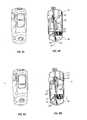
- Figures 1A, 2A, 3A, 4A, 5A, 6A, 7A, 7C, 8A, 9A and 10Aare perspective views of system(s) according to the present invention at various stages of operation.
- Figures 1B, 2B, 3B, 4B, 5B, 6B, 7B, 7D, 8B, 9B and 10Bare top-down cross sectional views of system(s) according to the present invention at various stages of operation.
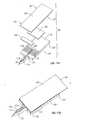
- Figures 11A and 11Bare perspective views of a preferred test strip for use in the present invention
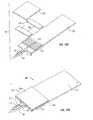
- figures 12A and 12Bare perspective views of another preferred test strip for use in the present invention.
- the deviceis a meter that includes actuation features for firing test strips 4.
- a screen 6is provided to display meter results and/or direct user action in connect with system 2 use.
- Other externally visible featuresinclude optional adjustment knob 8 , cap 10 and interlock button 12 .
- system 2comprises an upper body portion 14 and a lower body portion 16 . As shown in FIG 2A, the lower body portion is exposed upon removal of cap 10 .
- lower body portion 16is slidingly received by upper body portion 14.
- the relative motion between these two membersactuates the various elements within system 2 .
- the mechanismenables combination of two steps involved in lancing: namely the cocking of the launcher mechanism and the release of the launcher. Specifically, a single motion first cocks the mechanism and later releases the cocked mechanism.
- This design approachis similar to that of a center punch used in creating an indentation on a surface.
- pressing system 2 against the surface of the skinleads to a single step in performing a procedure that normally involves in excess of 10 to 15 steps.
- knob 8is preferably actuated by turning clockwise or counterclockwise to set the depth, or any other variable that may be necessary to adapt to a specific user (e.g., force on a pressure-ring), to which a lance portion 18 of test strip 4 will fire relative to a face 20 of the system.
- Face 20may serve as such a "pressure ring” in that when it is applied to the skin surface, it depresses tissue around a periphery of the intended wound site.
- the force on pressure ringmay be dictated by the compression force to slide the lower portion into the upper portion; upon application of this force, the test strip is typically also launched into the skin.
- the pressure formed at the site to be lanced, resulting at least in part from stretching the skin in this area,is useful for extracting a sample in that it helps "pump" material from the wound produced.
- Wound/penetration depthis preferably set to between about 0.02 mm and 2.0 mm, or more preferably set between 0.5 mm and 1.5 mm, by virtue of a screw-type interface 22 which advances or retracts an extension 24 carrying a stop portion 26 . Such adjustment action usually accomplished at this stage is indicated by the use of bold in connection with the elements at issue.
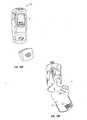
- FIGS 2A and 2Bshow cap 10 being removed from system 2 . It is slidingly received by lower body portion 16 . Detent features may be provided in order to prevent inadvertent separation of the elements.
- Removal of cap 10preferably turns the system "on" as indicated in FIG 2A. Where no cap is provided, another preliminary action may be required to activate the system (such as depressing a button) or system 2 could be activated by subsequent activity that is described.
- various user directions or messagesmay be displayed by the meter.
- display 6may present information regarding the number of test strips left, time to expiration, etc .
- FIG 3Billustrates actuation of button 12 for a different purpose (though, it could be used to turn the system on as well).
- button 12When a user depresses button 12 as shown, an interlocking interface 28 formed by an extension 30 of button 12 and another extension 32 of lower body portion 16 is released.
- a spring member 34may be provided to bias the button outwardly.
- any form of springmay be used in this regard. The same is true for other springs employed in the invention.
- leaf springsBy varying the internal configuration of system 2 flat springs, leaf springs, coil springs, torsion springs or extension springs may be used. What is more, metal or polymer spring members may be interchangeably used.
- a target sitemight be a patient's or user's finger, forearm, palm, or elsewhere.
- FIG 4Ashows an "apply" message on screen 6 as shown in FIG 4A.
- FIG 4Bshows the next action taken by a user.
- upper body portion 14is pushed toward the target site. This causes system 2 to collapse, with lower body portion 16 slidingly received within upper body portion 14 .
- Such user activityresults in several actions within device 2. For one, interlock portions 28 and 32 slide past each other (instead of interfering with each other's movement).
- a lancing mechanism 36 within system 2is cocked. This is accomplished by stressing launch spring 38 . While this may be accomplished otherwise, in the variation of the invention shown here, a lever arm 40 driven by a cocking extension 42 of lower body portion 16 provides the input.
- a lance interface member 44is held in a cocked position by a latch 46 and cooperative catch 48 at one end of the interface member.
- test strip interface features 50are provided. These pick up or interface with a test strip 4 . As shown, interface features advance a test strip slightly relative to other test strips contained within a magazine 52 .
- the magazinemay be configured in any convenient manner to allow loading of a large number of test strips therein (e.g ., between about 10 and 100, more preferably between 15 and 25) and release therefrom. Providing numerous test strips as possible in view of the magazine format employed by the present invention allows for greatly increased user convenience.
- Magazine 52is preferably spring-loaded in order to function properly regardless of orientation.
- the magazinepreferably has a door 136, which remains closed except during brief periods of time when the test strip is removed, serves as a moisture barrier. (A similar door or barrier may be provided for waste magazine 22 ).
- a drying agente.g ., a desiccate
- the mechanism driving the test strip and operating the dooris preferably configured so it will not leave a test strip partially advanced or the magazine open if the user were not to complete the total relative motion of sliding lower portion 16 into upper portion 14 .
- the magazinemay take the form of a removable cartridge or cassette as shown in FIG. 10A described further below. Especially under such circumstances, it may contain a barcode or some other means (such as a chip) for transferring information to the meter upon loading the same with test strips or a strip cartridge. In which case, the meter would automatically read this information when the magazine/cartridge is loaded into the system, via an optional detection system 138 (shown in FIG. 10B). Any conventional reader or placement as appropriate to the media by which the information is expressed may be employed.
- examples of information that may be usefulinclude: a calibration factor or code, number of strips remaining/used in magazine, number of days since magazine was installed and/or days until strip expiration (such as a hard date or a date that is a function of when the magazine was loaded into the system).
- system 2may include features to determine if it is working properly in reference to one or more control species, such as a control solution comprising glucose of a known concentration.
- FIGS 5A and 5Bshow activity in connection with lance/test strip firing preceding such action.
- motion of the lower body portion 16cams latch 46 to release spring loaded interface member 44 to travel, push magazine door 136 open, and pick-up a strip to advance it out of the magazine.
- an electronic solenoid(not shown) activated by electronics included in system 2 can be utilized to release latch 46 , whereupon interface member 44 , together with test strip 4 advances as indicated.
- interface member 44preferably urges the test element through guides 78 .
- test element/stripIn use, since only the needle end of a test element/strip comes in contact with a user, the opposite end of the device adjacent interface member 44 does not into contact with body fluids. Accordingly, this element is not able to contaminate unused test strips upon retraction past the same. Further, magazine door 136 is opened only for a very short time period, thereby minimizing opportunity for contamination. In addition (as further described below), used test strips are ejected from the system or stored in a (sealed) magazine in the cap and are never brought near the magazine. All of these factors may contribute to maintaining unused test strip quality.
- a tip 56 of the lance portion of the test stripis shown protruding slightly from the face 20 of system 2 .
- the meter screenpreferably directs a user to hold the device in place. This allows time for sample collection from the wound produced, such as by a pressure-ring to force fluid from the wound and capillary action along the lance member 18 . Still, it is to be noted that other driving forces, such as vacuum, may be employed to facilitate sample acquisition.
- the systempreferably directs the user to remove system 2 from the test site.
- a sufficient time intervale.g ., usually between about 0.1 and 15 seconds, preferably less than 3 seconds
- the systempreferably directs the user to remove system 2 from the test site.
- lower body portionreturns to its pre-compressed state.
- return spring 54urges the body portions away from each other as shown.
- an interface member return catch 58withdraws interface member 44 .
- Catch 58is preferably provided at an end of a return member 60 that is actuated by lever 40 , which is, in turn, associated with lower body portion 16 .
- Pivoting interface portions 62are preferred, though the parts may be integrally molded with living hinge sections or otherwise produced.
- FIG 6Bshows a test strip disposal mechanism 64 as it swings into position for action.
- the mechanismmay comprise a pusher arm 66 with a stop or interface portion 68 , a lever arm 70 and an intermediate link 72. These members may also be spring-loaded. Furthermore, there construction may vary in like manner to the other components noted directly above.
- disposal mechanism 64is shown at a rest position.
- a protrusion 74 at the end of lever arm 70is interfaced with a complementary pusher portion 76 of cap 10 ( see FIG 1B).
- the disposal mechanismmoves to the position shown in FIG 2B. From here, it is able to swing out of the way of lance firing as shown in FIG 4B.
- FIG 6Bit moves into position as seen in FIG 7B.
- interface portion 68is shown interfacing with a used strip 4'.
- the stripis at least partially confined by optional opposing guide members 78 .
- an adjacent meter element 80may be used to read the strip-especially where colorametric sensors are employed.
- the guides 78may serve the dual purpose of directing the test strip and also serving as electrical contacts to interface electrochemical strips to the meter, when this type of strip is used.
- the result obtained(or a result derived from the data obtained) is displayed on screen 6 as shown in FIG 7A.
- meter functionalitymay be identical to that in FIGS 7A and 7B.
- the disposal mechanism 64'is configured somewhat differently.
- the primary distinctionis observed in connection with extension 82 off of lever arm 70 .
- lever the extensionmake lever 70' suitable for manual operation. It is preferably actuated as indicated by the double-headed arrow along slot 84 shown in FIG 7C to eject spent test strips from system 2 .
- a userBefore actuating the lever extension, it is preferred that a user direct the device toward a suitably waste receptacle.
- FIGS 8A - 9BSuch a magazine is used as shown in FIGS 8A - 9B.
- cap 10may be replaced. In doing so tab or protrusion 74 of lever arm 70 is captured by cap interface 76 . This advances pusher arm 66 , causing interface section 68 to drive spent test strip 4' into waste magazine 86 .
- FIG 9A and 9Bshow cap 10 in place with system 2 restored to its configuration in FIGS 1A and 1B. At this point, spent strip 4' is fully deposited within magazine 86 . When the magazine is full, cap 10 may be thrown away en Toto . Such activity is shown in connection with FIGS. 10A and 10B.
- the magazine itselfmay be disengaged from the cap and be thrown away alone. Either way, used test strips thus-packaged for disposal minimize any disposal issues that are presented.
- cap 10is provided, thereby somewhat simplifying operation of the system. Still, it is possible to provide a system that includes a waste magazine and the ability for the user to individually dispose of test strips, as desired. Regardless, where manual test strip disposal features are provided as shown in FIGS 7C and 7D, release of button 12 to reactivate interlock 28 prior to actuating lever arm extension 82 is advised in order to prevent inadvertent movement of the body portions with respect to each other.
- one or both of the magazinesmay be manually inserted and/or removed in/from their respective housing portions.
- a detent mechanism or finger-actuated latch(not shown) may be provided to ensure retention. Removal of an empty cartridge 52 from the upper body portion is shown in FIG. 10B. Upon opening a door 140 , an empty unit may be discarded in favor of a full one or simply reloaded and replaced in the system. Utilizing a new cartridge marked with identification data as discussed above is, however, preferred.
- magazines 22 and/or 52may be produced with transparent material or an indicator may be provided to inform a user of its status.
- a open or transparent window in cover 10 or the body of the metermay be employed to allow the user to observe the quantity of unused strips in the magazine(s)/cassette(s).
- test stripswhich integrally include a biosensor and a forward-pointing lance member may be used in the present invention.
- those described in the co-pending European application with Attorney ref: P033762EP referred to abovemay be most preferred. Details regarding the production and use of such devices are presented therein. Regardless a brief description is provided below.
- FIGS 11A and 11Billustrate such an exemplary test strip or biosensor device 90 fully described in the above-referenced case.
- Device 90includes an electrochemical test strip configuration and a microneedle 92 integrated therewith.
- the biosensoris defined by an electrochemical cell generally having two spaced-apart and opposing electrodes 94 and 96 , respectively referred to herein as bottom electrode 94 and top electrode 96 , though in use they may oriented in any direction.
- At least the surfaces of electrodes 94 and 96 facing each otherare comprised of a conductive layer 98 and 100 , respectively, such as a metal, deposited on an inert substrate 102 and 104 , respectively.
- the spacing between the two electrodesis a result of the presence of a spacer layer 106 positioned or sandwiched between electrodes 94 and 96 .
- Spacer layer 106preferably has double-sided adhesive to hold the electrodes.
- the spacer layeris preferably configured or cut so as to provide a reaction zone or area 108 .
- a redox reagent system or composition 110is present within reaction zone 108 , where the reagent system is selected to interact with targeted components in the fluid sample, typically whole blood, during an assay of the sample.
- Redox reagent system 110is usually deposited on the conductive layer 100 of top electrode 96 wherein, when in a completely assembled form (as shown in Fig. 10B), redox reagent system 110 resides within reaction zone 108 .
- bottom electrode 94serves as a counter/reference electrode and top electrode 96 serves as the working electrode of the electrochemical cell.
- the role of the electrodescan be reversed such that the bottom electrode serves as a working electrode and top electrode serves as a counter/reference electrode.
- Microneedle 92is preferably integrally formed with and extends from bottom electrode 94 .
- the microneedleis shown with a space-defining configuration in the form of a concave recess 112 within its top surface.
- the recesscreates a corresponding space within skin tissue upon penetration of microneedle 92 into the skin. This space acts as a sample fluid collection reservoir wherein fluid released upon penetration is pooled within the space prior to transfer into the electrochemical cell.
- An opening 114 to further expose the pooling area defined by recess 112 to the outside environmentmay also be included, thereby increasing the volume and flow rate of body fluid into the pooling area.
- Biosensor device 90further includes a sample fluid transfer or extraction pathway or channel 116 which extends from recess 112 to within the biosensor. At least a portion of a proximal end of the pathway resides within the biosensor portion of device 90 , specifically within reaction zone 108 , and a portion of a distal end of pathway 114 resides within microneedle 92 .
- Pathway 116is dimensioned so as to exert a capillary force on fluid within the pooling area defined by recess 112 , and draws or wicks physiological sample to within the reaction zone.
- Extending laterally from proximal portion 114 of the pathway to within a portion or the entirety of the reaction zoneare sub-channels 118. The sub-channels facilitate the filling of reaction zone 108 with the sampled fluid.
- FIGS 12A and 12Billustrate another suitable embodiment of a biosensor/skin-piercing device 90' which is also disclosed in the co-pending European application with Attorney ref: P033762EP referred to above.
- Device 90'has a photometric/colorimetric biosensor configuration and a microneedle 92' integrated therewith.
- the colorimetric or photometric biosensoris generally made up of at least the following components: a support element or substrate 120 made of either an inert material, including suitable plastics, or a metal material, a matrix or matrix area 122 for receiving a sample, a reagent composition 124 within the matrix area, the reagent composition typically including one or more members of an analyte oxidation signal producing system, an air venting port (not shown) and a top layer 126 which covers at least matrix 122 .
- top layer 126may be a membrane containing a reagent composition impregnated therein while the matrix 122 may or may not contain reagent composition.
- test strip 90'may include a double-sided adhesive layer 128 situated between substrate 120 and membrane 126 to hold them together.
- Double-sided adhesive layer 130has a cutout portion 132 which corresponds to the area of matrix 122 and defines an area for deposition of the sampled physiological fluid and for the various members of the signal producing system.
- Microneedle 92is preferably formed with and extends from substrate 120 and has a space-defining configuration in the form of an opening 114 which extends transverse to a dimension, e.g ., width or thickness, of microneedle 92' .
- opening 114forms an open space within the tissue upon penetration of the microneedle into the skin.
- Such open spaceacts as a sample fluid collection reservoir wherein fluid released upon penetration is pooled within the space prior to transfer into the photometric/ colorimetric cell.
- the needle variation shown in FIGS 11A and 11Bmay instead rely solely on a recess and omit a through-hole.
- Biosensor device 90'hosts a sample fluid transfer or extraction pathway 116 having a distal end which extends within a portion of microneedle 92' and terminates at a distal opening 114 . At least a portion of the proximal end of pathway 116 resides within the biosensor portion of device, specifically within matrix area 122 . Pathway 116 is dimensioned so as to exert a capillary force on fluid within the pooling area defined by opening 114 , and draws or wicks physiological sample to within matrix area 122 . Extending laterally from proximal portion of pathway 116 to within a portion or the entirety of matrix area 122 are sub-channels 134 , which facilitate the filling of matrix or matrix area 122 with the sampled fluid.
Landscapes
- Health & Medical Sciences (AREA)
- Life Sciences & Earth Sciences (AREA)
- Physics & Mathematics (AREA)
- Engineering & Computer Science (AREA)
- Medical Informatics (AREA)
- Animal Behavior & Ethology (AREA)
- Pathology (AREA)
- Veterinary Medicine (AREA)
- Biomedical Technology (AREA)
- Heart & Thoracic Surgery (AREA)
- Public Health (AREA)
- Molecular Biology (AREA)
- Surgery (AREA)
- Biophysics (AREA)
- General Health & Medical Sciences (AREA)
- Hematology (AREA)
- Dermatology (AREA)
- Emergency Medicine (AREA)
- Optics & Photonics (AREA)
- Manufacturing & Machinery (AREA)
- Geometry (AREA)
- Measurement Of The Respiration, Hearing Ability, Form, And Blood Characteristics Of Living Organisms (AREA)
- Investigating Or Analysing Biological Materials (AREA)
Abstract

Description
- This invention relates to systems for obtaining physiologic fluid samples.More particularly, a test system for obtaining and testing blood samples withminimum user effort is described.
- Analyte concentration determination in physiological samples is of everincreasing importance to today's society. Such assays find use in a variety ofapplication settings, including clinical laboratory testing, home testing,etc., wherethe results of such testing play a prominent role in the diagnosis and managementof a variety of disease conditions. Analytes of interest include glucose fordiabetes management, cholesterol for monitoring cardiovascular conditions, drugsfor monitoring levels of therapeutic agents or identifying illegal/illegal levels ofdrugs, and the like. In response to this growing importance of analyteconcentration determination, a variety of analyte concentration determinationprotocols and devices for both clinical and home testing have been developed
- In determining the concentration of an analyte in a physiological sample, aphysiological sample must first be obtained. Obtaining and testing the sampleoften involves cumbersome and complicated procedures. Unfortunately,successful manipulation and handling of test elements, lancing members, metersand the like is to a great extent dependent on the visual acuity and manualdexterity of the user, which in the case of people with diabetes is subject to deterioration over the course of the disease state. In extreme cases people thathave significant loss of sight and sensation, testing procedures can becomesignificantly difficult and requires additional assistance from ancillary devices orpersonnel.
- A typical procedure involved with making a glucose measurementinvolves the following actions or steps (but not necessarily in the order given):
- 1) removing supplies from a carrying case,
- 2) removing a lancing device loading cap or door,
- 3) removing and disposing of an old lancet form the lancingdevice,
- 4) inserting the lancet in the lancing device,
- 5) twisting off a protective cap from the lancet,
- 6) replacing the lancing device cap.
- 7) cocking the lancing device,
- 8) opening a test strip vial/ container,
- 9) removing a strip from the container and inserting or interfacingit with a meter,
- 10) holding a lancing device to the skin,
- 11) firing the lancing device,
- 12) lifting the lancing device and setting aside,
- 13) extracting a sample,
- 14) applying sample to the test strip and getting results,
- 15) disposing of the test strip,
- 16) cleaning the test site, and
- 17) returning supplies to the carrying case. Sometimes fewer steps are involved. One manner of reducing the number ofactions is by integrated devices set to combine multiple functions.
- In this regard, certain test strip dispensers are configured to both store andadvance successive test strips upon actuation. Examples of such devices arepresented in U.S. Patent Nos. 5,510,266; 5,575,403, 5,797,693 and possibly inPCT Publication WO 01/63272. In addition some dispensers also include meterfunctionality. Examples of such of systems that integrate test strip meter anddispenser combination functions are disclosed in U.S. Patent No, 5,736,103, 5,757,666 and PCT Publication WO 99/44508. Furthermore, the device describedin WO 01/23885 includes all of the above features, plus a receptacle to receivespent test strip elements that are cut off of a continuous roll of the same.
- Another class of devices designed to decrease the number of stepsrequired in test strip use includes automatic or semi-automatic lancing devices.U.S. Patent No. 6,228,100 discloses a structure configured for sequential firing ofa number of lancets, one at a time, in order to eliminate the requirement that auser remove and replace each lancet individually before and after use.
- The device disclosed in U.S. Patent No. 5,971,941 attempts to combine thefunctionality of each of the preceding classes of test strip devices. In effort toprovide an "integrated" system for sampling blood and analysis thereof, itincludes a magazine of test strips, test strip advancement and dispensing features,a meter with a display and an automated lancing mechanism all housed with asingle box. While presenting some measure of advance in user convenience, thetest strip and lancing features are removed from each other causing the user totake two steps in lancing and transferring sample to a test strip. Furthermore, thedevice includes no provisions for used test strips.
- While certain combination test strip and lancing systems that do notrequire that a subject to move the device relative to the sample site in use (e.g.,the systems described in U.S. Patent Nos. 6,352,514; 6,332,871; 6,183,489;6,099,484; 6,056,701 and 5,820,570), some of these systems are quite complexand, consequently, either difficult to operate or costly to produce. In addition,some involve changing-out spent test and/or lancet members one-at-a-time. This is true with respect to the systems described in U.S. Patent Nos. 6,027,459;6,063,039; 6,071,251 and 6,283,926 as well as for certain embodiments disclosedin PCT Publication WO 01/64105.
- However, another embodiment presented in that reference provides formultiple lancet/sensor pairs that only need to be changed out after the disksincluding each are spent. An exemplary number of a dozen such radially-orientedpairs is provided. WO 02/49507 also discloses a meterincluding a multiple sensor/tester element. Fluid extracted from a subject by amicroneedle at a common entrance port is selectively switched between a numberof microchannels by means of electro-osmotic pumps and hydrophobic gates.The present invention is distinguished from each of these inventions in terms ofits modular use of combination test strip and sensor elements, in which unexposeditems may be sealed-off from contamination, and possibly provided in greaternumber, as well as in the simplicity of the present invention which preferablyinvolves mechanical movement for sample acquisition and handling.
- Of course, such advantages may be present in systems according to theinvention in various degrees. It is intended that, in one way or another, theinvention is of assistance in reducing barriers to patient self-monitoring andtherefore result in improved outcomes in the management of disease, such asdiabetes.
- A preferred variation of the invention truly minimizes the steps requiredfor analyte test strip use as defined above. As practiced with each of the optionalfeatures, the present invention merely involves four such user steps. Theseinclude: providing a system according to the present invention, placing it against atest site, pushing the system body portions together and reading a test result. Thesystem is then removed and put away. It may include a cap to be removedinitially and replaced finally.
- In a preferred variation of the invention, such a cap includes a magazinethat automatically receives spent or used test strips. In another variation of theinvention (one in which test strips are merely ejected) a user disposal step may beadded.
- The system of the present invention utilizes disposable test strip elementsthat include an integral lancet. Examples of such strips include those described inEP-A-1 281 352, EP-A-1 284 121 and European patent application No.claiming priority from USSN 10/143,399 filed on 9th May 2002 [Attorney ref:P033762EP]. The needle may be configured to collect blood, interstitial fluid,other body fluids, or any combination thereof. Regardless of the type of stripchosen and sample to be collected, the members are stored in a magazine, fromwhich they are fired to produce a wound to receive sample therefrom.
- The action provided by the meter/dispenser of the present invention ispreferably implemented by a series of links, levers and spring elements such thatadvancement of an upper body portion relative to a lower body portion restingagainst a test site causes a test strip to be taken from the magazine advanced to form a stick and collect sample. Following such action, the meter may beremoved, test results are displayed and such action as desired to dispose of theused test strip occurs.
- Each of the figures diagrammatically illustrates aspects of the invention.To facilitate understanding, the same reference numerals have been used (wherepractical) to designate similar elements that are common to the figures. Somesuch numbering has, however, been omitted for the sake of drawing clarity.
- Figures 1A, 2A, 3A, 4A, 5A, 6A, 7A, 7C, 8A, 9A and 10A are perspectiveviews of system(s) according to the present invention at various stages ofoperation.
- Figures 1B, 2B, 3B, 4B, 5B, 6B, 7B, 7D, 8B, 9B and 10B are top-downcross sectional views of system(s) according to the present invention at variousstages of operation.
- Figures 11A and 11B are perspective views of a preferred test strip for usein the present invention; figures 12A and 12B are perspective views of anotherpreferred test strip for use in the present invention.
- In describing the invention in greater detail than provided in the Summaryabove, details of an embodiment of the invention together with aspects of systemuse. Two alternate variations of the invention are described in this manner,though other variations are possible. Finally, examples of a preferred test strip foruse in the device are disclosed.
- Before the present invention is described in such detail, however, it is tobe understood that this invention is not limited to particular variations set forthand may, of course, vary. Various changes may be made to the inventiondescribed and equivalents may be substituted without departing from the truespirit and scope of the invention. In addition, many modifications may be madeto adapt a particular situation, material, composition of matter, process, processact(s) or step(s), to the objective(s), spirit or scope of the present invention. Allsuch modifications are intended to be within the scope of the claims made herein.
- Methods recited herein may be carried out in any order of the recitedevents which is logically possible, as well as the recited order of events.Furthermore, where a range of values is provided, it is understood that everyintervening value, between the upper and lower limit of that range and any otherstated or intervening value in that stated range is encompassed within theinvention. Also, it is contemplated that any optional feature of the inventivevariations described may be set forth and claimed independently, or incombination with any one or more of the features described herein.
- All existing subject matter mentioned herein (e.g., publications, patents,patent applications and hardware) is incorporated by reference herein in itsentirety except insofar as the subject matter may conflict with that of the presentinvention (in which case what is present herein shall prevail). The referenceditems are provided solely for their disclosure prior to the filing date of the presentapplication. Nothing herein is to be construed as an admission that the presentinvention is not entitled to antedate such material by virtue of prior invention.
- Reference to a singular item, includes the possibility that there are pluralof the same items present. More specifically, as used herein and in the appendedclaims, the singular forms "a," "and," "said" and "the" include plural referentsunless the context clearly dictates otherwise. It is further noted that the claimsmay be drafted to exclude any optional element. As such, this statement isintended to serve as antecedent basis for use of such exclusive terminology as"solely," "only" and the like in connection with the recitation of claim elements,or use of a "negative" limitation. Last, it is to be appreciated that unless definedotherwise, all technical and scientific terms used herein have the same meaning ascommonly understood by one of ordinary skill in the art to which this inventionbelongs.
- Turning now to FIGS 1A and 1B an
exemplary system 2 according to thepresent invention is disclosed. The device is a meter that includes actuationfeatures for firingtest strips 4. Ascreen 6 is provided to display meter resultsand/or direct user action in connect withsystem 2 use. Other externally visiblefeatures includeoptional adjustment knob 8,cap 10 andinterlock button 12. - Whether all or none of these optional features are included,
system 2comprises anupper body portion 14 and alower body portion 16. As shown inFIG 2A, the lower body portion is exposed upon removal ofcap 10. - In operation,
lower body portion 16 is slidingly received byupper bodyportion 14. The relative motion between these two members actuates the variouselements withinsystem 2. As described further below, the mechanism enables combination of two steps involved in lancing: namely the cocking of the launchermechanism and the release of the launcher. Specifically, a single motion firstcocks the mechanism and later releases the cocked mechanism. This designapproach is similar to that of a center punch used in creating an indentation on asurface. In combination with a test strip integrating a biosensor and lancet,pressingsystem 2 against the surface of the skin leads to a single step inperforming a procedure that normally involves in excess of 10 to 15 steps. - As shown in FIGS 1A and 1B,
system 2 is in an "off " mode. In this mode,knob 8 is preferably actuated by turning clockwise or counterclockwise to set thedepth, or any other variable that may be necessary to adapt to a specific user (e.g.,force on a pressure-ring), to which alance portion 18 oftest strip 4 will firerelative to aface 20 of the system.Face 20 may serve as such a "pressure ring" inthat when it is applied to the skin surface, it depresses tissue around a periphery ofthe intended wound site. The force on pressure ring may be dictated by thecompression force to slide the lower portion into the upper portion; uponapplication of this force, the test strip is typically also launched into the skin. Thepressure formed at the site to be lanced, resulting at least in part from stretchingthe skin in this area, is useful for extracting a sample in that it helps "pump"material from the wound produced. - Wound/penetration depth is preferably set to between about 0.02 mm and2.0 mm, or more preferably set between 0.5 mm and 1.5 mm, by virtue of ascrew-
type interface 22 which advances or retracts an extension24 carrying astop portion 26. Such adjustment action usually accomplished at this stage is indicatedby the use of bold in connection with the elements at issue. - FIGS 2A and 2B show
cap 10 being removed fromsystem 2. It isslidingly received bylower body portion 16. Detent features may be provided inorder to prevent inadvertent separation of the elements. - Removal of
cap 10 preferably turns the system "on" as indicated in FIG2A. Where no cap is provided, another preliminary action may be required toactivate the system (such as depressing a button) orsystem 2 could be activatedby subsequent activity that is described. - In any event, as shown in the other figures, various user directions ormessages may be displayed by the meter. In addition to displaying test resultsand directions,
display 6 may present information regarding the number of teststrips left, time to expiration,etc. - FIG 3B illustrates actuation of
button 12 for a different purpose (though, itcould be used to turn the system on as well). When a user depressesbutton 12 asshown, an interlockinginterface 28 formed by anextension 30 ofbutton 12 andanotherextension 32 oflower body portion 16 is released. A spring member34may be provided to bias the button outwardly. - Any form of spring may be used in this regard. The same is true for othersprings employed in the invention. By varying the internal configuration of
system 2 flat springs, leaf springs, coil springs, torsion springs or extensionsprings may be used. What is more, metal or polymer spring members may beinterchangeably used. - Regardless of such constructional details, with
face 20 exposed andinterlock orsafety mechanism 28 set free (most preferably by depressing button12) the face is set against a target site. Such a target site might be a patient's oruser's finger, forearm, palm, or elsewhere. - With
system 2 so positioned an "apply" message may appear onscreen 6as shown in FIG 4A. Whether prompted in this manner or not, FIG 4B shows thenext action taken by a user. Here,upper body portion 14 is pushed toward thetarget site. This causessystem 2 to collapse, withlower body portion 16 slidinglyreceived withinupper body portion 14. - Such user activity results in several actions within
device 2. For one,interlock portions mechanism 36 withinsystem 2 iscocked. This is accomplished by stressinglaunch spring 38. While this may beaccomplished otherwise, in the variation of the invention shown here, alever arm 40 driven by a cockingextension 42 oflower body portion 16 provides the input.Alance interface member 44 is held in a cocked position by alatch 46 andcooperative catch 48 at one end of the interface member. - At the other end of
interface member 44, test strip interface features50 areprovided. These pick up or interface with atest strip 4. As shown, interfacefeatures advance a test strip slightly relative to other test strips contained within amagazine 52. - The magazine may be configured in any convenient manner to allowloading of a large number of test strips therein (e.g., between about 10 and 100, more preferably between 15 and 25) and release therefrom. Providing numeroustest strips as possible in view of the magazine format employed by the presentinvention allows for greatly increased user convenience.
Magazine 52 is preferably spring-loaded in order to function properlyregardless of orientation. The magazine preferably has adoor 136, which remainsclosed except during brief periods of time when the test strip is removed, servesas a moisture barrier. (A similar door or barrier may be provided for wastemagazine22). Also, a drying agent (e.g., a desiccate) may be contained withinthe magazine to protect the test strips' reagent from moisture. To further preservethe integrity of unused test strips, the mechanism driving the test strip andoperating the door is preferably configured so it will not leave a test strip partiallyadvanced or the magazine open if the user were not to complete the total relativemotion of slidinglower portion 16 intoupper portion 14.- The magazine, may take the form of a removable cartridge or cassette asshown in FIG. 10A described further below. Especially under suchcircumstances, it may contain a barcode or some other means (such as a chip) fortransferring information to the meter upon loading the same with test strips or astrip cartridge. In which case, the meter would automatically read thisinformation when the magazine/cartridge is loaded into the system, via anoptional detection system138 (shown in FIG. 10B). Any conventional reader orplacement as appropriate to the media by which the information is expressed maybe employed. Regardless of such constructional details, examples of informationthat may be useful include: a calibration factor or code, number of strips remaining/used in magazine, number of days since magazine was installed and/ordays until strip expiration (such as a hard date or a date that is a function of whenthe magazine was loaded into the system).
- Further optional feature(s) that may be included in
meter 2 includediagnosis or calibration system(s). For example,system 2 may include features todetermine if it is working properly in reference to one or more control species,such as a control solution comprising glucose of a known concentration. - The relative motion between
body portions return spring 54. Its use will be described further below. - FIGS 5A and 5B, show activity in connection with lance/test strip firingpreceding such action. In one variation, motion of the
lower body portion 16cams latch46 to release spring loadedinterface member 44 to travel, pushmagazine door 136 open, and pick-up a strip to advance it out of the magazine.Alternately, an electronic solenoid (not shown) activated by electronics includedinsystem 2 can be utilized to releaselatch 46, whereuponinterface member 44,together withtest strip 4 advances as indicated. As it advances toward the skin,interface member 44 preferably urges the test element through guides78. - In use, since only the needle end of a test element/strip comes in contactwith a user, the opposite end of the device
adjacent interface member 44 does notinto contact with body fluids. Accordingly, this element is not able tocontaminate unused test strips upon retraction past the same. Further,magazinedoor 136 is opened only for a very short time period, thereby minimizingopportunity for contamination. In addition (as further described below), used test strips are ejected from the system or stored in a (sealed) magazine in the cap andare never brought near the magazine. All of these factors may contribute tomaintaining unused test strip quality. - A
tip 56 of the lance portion of the test strip is shown protruding slightlyfrom theface 20 ofsystem 2. As shown in FIG 5A, the meter screen preferablydirects a user to hold the device in place. This allows time for sample collectionfrom the wound produced, such as by a pressure-ring to force fluid from thewound and capillary action along thelance member 18. Still, it is to be noted thatother driving forces, such as vacuum, may be employed to facilitate sampleacquisition. - Following a sufficient time interval, (e.g., usually between about 0.1 and15 seconds, preferably less than 3 seconds), as shown in FIG 6A, the systempreferably directs the user to remove
system 2 from the test site. By such action,as shown in FIG 6B, lower body portion returns to its pre-compressed state.Preferably returnspring 54 urges the body portions away from each other asshown. As the body portions separate, an interfacemember return catch 58withdrawsinterface member 44.Catch 58 is preferably provided at an end of areturn member60 that is actuated bylever 40, which is, in turn, associated withlower body portion 16. Pivotinginterface portions 62 are preferred, though theparts may be integrally molded with living hinge sections or otherwise produced. - In addition to showing the movement of the body portions relative to eachother in an intermediate state, FIG 6B shows a test
strip disposal mechanism 64 asit swings into position for action. The mechanism may comprise apusher arm 66 with a stop orinterface portion 68, alever arm 70 and anintermediate link 72.These members may also be spring-loaded. Furthermore, there construction mayvary in like manner to the other components noted directly above. - In order for the members of the disposal mechanism to reach the locationshown in FIG 6B, as it progresses to that shown in FIG 7B (or 7D), certainantecedent actions may have occurred. These are illustrated in connection withFIGS 1B, 2B and 4B.
- In FIG 1 A,
disposal mechanism 64 is shown at a rest position. Aprotrusion 74 at the end oflever arm 70 is interfaced with acomplementarypusher portion 76 of cap10 (see FIG 1B). Upon removal of the cap, the disposalmechanism moves to the position shown in FIG 2B. From here, it is able to swingout of the way of lance firing as shown in FIG 4B. Ultimately, as illustrated inFIG 6B, it moves into position as seen in FIG 7B. - In FIG 7B,
interface portion 68 is shown interfacing with a used strip 4'.The strip is at least partially confined by optional opposingguide members 78. Inthis location anadjacent meter element 80 may be used to read the strip-especiallywhere colorametric sensors are employed. Alternately, whereelectrochemical test strips are used, theguides 78 may serve the dual purpose ofdirecting the test strip and also serving as electrical contacts to interfaceelectrochemical strips to the meter, when this type of strip is used. - The result obtained (or a result derived from the data obtained) isdisplayed on
screen 6 as shown in FIG 7A. - In the variation of the invention in FIGS 7C and 7D, meter functionalitymay be identical to that in FIGS 7A and 7B. However, in the variation shown inFIGS 7C and 7D, the disposal mechanism64'is configured somewhat differently.The primary distinction is observed in connection with
extension 82 off ofleverarm 70. Instead of being configured to interface with a cap, lever the extensionmake lever70' suitable for manual operation. It is preferably actuated asindicated by the double-headed arrow alongslot 84 shown in FIG 7C to ejectspent test strips fromsystem 2. Before actuating the lever extension, it ispreferred that a user direct the device toward a suitably waste receptacle. - Whether or not manual test strip disposal features are included in
system 2, it may be preferred to includewaste magazine 86 incap 10. Such a magazineis used as shown in FIGS 8A - 9B. At any time aftersystem 2 is removed fromthe test site (for instance, in response to meter screen directions provided in FIG6A),cap 10 may be replaced. In doing so tab orprotrusion 74 oflever arm 70 iscaptured bycap interface 76. This advancespusher arm 66, causinginterfacesection 68 to drive spent test strip4' intowaste magazine 86. The addition ofspent strips to its cache of spent strips held in place by biasingspring 88eventually fills the magazine. FIG 9A and 9B showcap 10 in place withsystem 2restored to its configuration in FIGS 1A and 1B. At this point, spent strip4' isfully deposited withinmagazine 86. When the magazine is full,cap 10 may bethrown awayen Toto. Such activity is shown in connection with FIGS. 10A and10B. - Alternately, the magazine itself may be disengaged from the cap and bethrown away alone. Either way, used test strips thus-packaged for disposalminimize any disposal issues that are presented.
- Still, at least in connection with the system approach taught in FIGS 7Cand 7D, it may be preferred no
cap 10 is provided, thereby somewhat simplifyingoperation of the system. Still, it is possible to provide a system that includes awaste magazine and the ability for the user to individually dispose of test strips, asdesired. Regardless, where manual test strip disposal features are provided asshown in FIGS 7C and 7D, release ofbutton 12 to reactivateinterlock 28 prior toactuatinglever arm extension 82 is advised in order to prevent inadvertentmovement of the body portions with respect to each other. - Furthermore, one or both of the magazines may be manually insertedand/or removed in/from their respective housing portions. In either case, a detentmechanism or finger-actuated latch (not shown) may be provided to ensureretention. Removal of an
empty cartridge 52 from the upper body portion isshown in FIG. 10B. Upon opening adoor 140, an empty unit may be discarded infavor of a full one or simply reloaded and replaced in the system. Utilizing a newcartridge marked with identification data as discussed above is, however,preferred. - As shown in FIG. 10, action associated with refill, replacement or disposalof test strips or ancillary equipment may be indicated on
readout 6 whenappropriate. Alternately, or additionally,magazines 22 and/or52 may beproduced with transparent material or an indicator may be provided to inform a user of its status. A open or transparent window incover 10 or the body of themeter may be employed to allow the user to observe the quantity of unused stripsin the magazine(s)/cassette(s). - As noted above, many types of test strips which integrally include abiosensor and a forward-pointing lance member may be used in the presentinvention. However, of the examples given, those described in the co-pendingEuropean application with Attorney ref: P033762EP referredto above may be most preferred. Details regarding the production and useof such devices are presented therein. Regardless a brief description is providedbelow.
- FIGS 11A and 11B illustrate such an exemplary test strip or
biosensordevice 90 fully described in the above-referenced case.Device 90 includes anelectrochemical test strip configuration and a microneedle92 integrated therewith.The biosensor is defined by an electrochemical cell generally having two spaced-apartand opposingelectrodes bottomelectrode 94 andtop electrode 96, though in use they may oriented in anydirection. At least the surfaces ofelectrodes conductive layer inert substrate spacer layer 106 positioned orsandwiched betweenelectrodes Spacer layer 106 preferably hasdouble-sided adhesive to hold the electrodes. The spacer layer is preferably configured or cut so as to provide a reaction zone orarea 108. A redox reagentsystem orcomposition 110 is present withinreaction zone 108, where the reagentsystem is selected to interact with targeted components in the fluid sample,typically whole blood, during an assay of the sample.Redox reagent system 110is usually deposited on theconductive layer 100 oftop electrode 96 wherein,when in a completely assembled form (as shown in Fig. 10B),redox reagentsystem 110 resides withinreaction zone 108. With such a configuration,bottomelectrode 94 serves as a counter/reference electrode andtop electrode 96 serves asthe working electrode of the electrochemical cell. However, in otherembodiments, depending on the voltage sequence applied to the cell, the role ofthe electrodes can be reversed such that the bottom electrode serves as a workingelectrode and top electrode serves as a counter/reference electrode. Microneedle 92 is preferably integrally formed with and extends frombottom electrode 94. The microneedle is shown with a space-definingconfiguration in the form of aconcave recess 112 within its top surface. Therecess creates a corresponding space within skin tissue upon penetration ofmicroneedle 92 into the skin. This space acts as a sample fluid collectionreservoir wherein fluid released upon penetration is pooled within the space priorto transfer into the electrochemical cell. Anopening 114 to further expose thepooling area defined byrecess 112 to the outside environment may also beincluded, thereby increasing the volume and flow rate of body fluid into thepooling area.Biosensor device 90 further includes a sample fluid transfer or extractionpathway orchannel 116 which extends fromrecess 112 to within the biosensor.At least a portion of a proximal end of the pathway resides within the biosensorportion ofdevice 90, specifically withinreaction zone 108, and a portion of adistal end ofpathway 114 resides withinmicroneedle 92.Pathway 116 isdimensioned so as to exert a capillary force on fluid within the pooling areadefined byrecess 112, and draws or wicks physiological sample to within thereaction zone. Extending laterally fromproximal portion 114 of the pathway towithin a portion or the entirety of the reaction zone are sub-channels118. Thesub-channels facilitate the filling ofreaction zone 108 with the sampled fluid.- FIGS 12A and 12B illustrate another suitable embodiment of abiosensor/skin-piercing device90' which is also disclosed in the co-pendingEuropean application with Attorney ref: P033762EP referredto above. Device90' has a photometric/colorimetric biosensorconfiguration and a microneedle92' integrated therewith. The colorimetric orphotometric biosensor is generally made up of at least the following components:a support element or
substrate 120 made of either an inert material, includingsuitable plastics, or a metal material, a matrix ormatrix area 122 for receiving asample, areagent composition 124 within the matrix area, the reagentcomposition typically including one or more members of an analyte oxidationsignal producing system, an air venting port (not shown) and atop layer 126which covers atleast matrix 122. In some embodiments,top layer 126 may be amembrane containing a reagent composition impregnated therein while thematrix 122 may or may not contain reagent composition. Further, test strip90' mayinclude a double-sided adhesive layer128 situated betweensubstrate 120 andmembrane 126 to hold them together. Double-sided adhesive layer 130 has acutoutportion 132 which corresponds to the area ofmatrix 122 and defines an areafor deposition of the sampled physiological fluid and for the various members ofthe signal producing system. Microneedle 92 is preferably formed with and extends fromsubstrate 120and has a space-defining configuration in the form of anopening 114 whichextends transverse to a dimension,e.g., width or thickness, of microneedle92'.As withrecess 112 ofmicroneedle 90 above, opening114 forms an open spacewithin the tissue upon penetration of the microneedle into the skin. Such openspace acts as a sample fluid collection reservoir wherein fluid released uponpenetration is pooled within the space prior to transfer into the photometric/colorimetric cell. Note, however, that the needle variation shown in FIGS 11Aand 11B may instead rely solely on a recess and omit a through-hole.- Biosensor device90' hosts a sample fluid transfer or
extraction pathway 116 having a distal end which extends within a portion of microneedle92' andterminates at adistal opening 114. At least a portion of the proximal end ofpathway 116 resides within the biosensor portion of device, specifically withinmatrix area 122.Pathway 116 is dimensioned so as to exert a capillary force onfluid within the pooling area defined by opening114, and draws or wicksphysiological sample to withinmatrix area 122. Extending laterally fromproximal portion ofpathway 116 to within a portion or the entirety ofmatrix area 122 are sub-channels134, which facilitate the filling of matrix ormatrix area 122with the sampled fluid. - Though the invention has been described in reference to certain examples,optionally incorporating various features, the invention is not to be limited to theset-ups described. The invention is not limited to the uses noted or by way of theexemplary description provided herein. It is to be understood that the breadth ofthe present invention is to be limited only by the literal or equitable scope of thefollowing claims.
Claims (10)
- An analyte detection system comprising:wherein said body portions are adapted so compressive movement between eachadvances said interface member to take a test strip from said magazine and pass at least alance portion of said test strip past a face of said second body portion to penetrate a tissuesite.a first body portion and a second body portion, said second body portion slidablyreceived by said first body portion, a magazine adapted to receive a plurality of unusedtest strip members and a test strip interface member,
- The system of claim 1, wherein said magazine is carried by said second bodyportion and said adaptation comprises a lever carried by said first body portion, said leverhaving a first end and a second end, wherein said first end is actuated by said secondbody portion to cock a spring between said second end and said interface member forfiring a test strip member.
- The system of claim 1 or claim 2, further comprising a button, wherein saidbody portions are adapted to be moveable relative to each other upon depressingsaid button.
- The system of any one of claims 1 to 3, further comprising a meter testelement and a meter screen.
- The system of any one of claims 1 to 4, further comprising a test stripdisposal mechanism including a pusher arm with a disposal interface portion, alever arm, and an intermediate link between said arm and said disposal interfaceportion.
- The system of any one of claims 1 to 5, further comprising a cap.
- The system of claim 7, wherein said cap carries a magazine adapted to receive aplurality of used test strip members.
- The system of any one of claims 1 to 7, further comprising a plurality of teststrip members, each comprising a sensor and at least one forward-facing lance member.
- The system of claim 8, wherein said plurality of test strip members are providedin a cartridge.
- A method of testing for analyte concentration in a biological sample comprising:providing a system as described in any one of claims 1 to 9,placing said second body portion face against a test site,forcing said body portions toward each other to cock and fire a test strip member,removing said system from the test site; anddisplaying results on a meter screen.
Priority Applications (1)
| Application Number | Priority Date | Filing Date | Title |
|---|---|---|---|
| EP08075676AEP1980206B1 (en) | 2002-05-09 | 2003-05-08 | Minimal procedure analyte test system |
Applications Claiming Priority (2)
| Application Number | Priority Date | Filing Date | Title |
|---|---|---|---|
| US10/142,443US7303726B2 (en) | 2002-05-09 | 2002-05-09 | Minimal procedure analyte test system |
| US142443 | 2002-05-09 |
Related Child Applications (1)
| Application Number | Title | Priority Date | Filing Date |
|---|---|---|---|
| EP08075676ADivisionEP1980206B1 (en) | 2002-05-09 | 2003-05-08 | Minimal procedure analyte test system |
Publications (2)
| Publication Number | Publication Date |
|---|---|
| EP1362551A1true EP1362551A1 (en) | 2003-11-19 |
| EP1362551B1 EP1362551B1 (en) | 2008-09-03 |
Family
ID=29269705
Family Applications (2)
| Application Number | Title | Priority Date | Filing Date |
|---|---|---|---|
| EP08075676AExpired - LifetimeEP1980206B1 (en) | 2002-05-09 | 2003-05-08 | Minimal procedure analyte test system |
| EP03252880AExpired - LifetimeEP1362551B1 (en) | 2002-05-09 | 2003-05-08 | Minimal procedure analyte test system |
Family Applications Before (1)
| Application Number | Title | Priority Date | Filing Date |
|---|---|---|---|
| EP08075676AExpired - LifetimeEP1980206B1 (en) | 2002-05-09 | 2003-05-08 | Minimal procedure analyte test system |
Country Status (14)
| Country | Link |
|---|---|
| US (1) | US7303726B2 (en) |
| EP (2) | EP1980206B1 (en) |
| JP (1) | JP4383090B2 (en) |
| KR (1) | KR100995479B1 (en) |
| CN (1) | CN1331440C (en) |
| AT (2) | ATE406838T1 (en) |
| CA (1) | CA2427542C (en) |
| DE (2) | DE60330924D1 (en) |
| ES (1) | ES2312726T3 (en) |
| IL (1) | IL155344A (en) |
| PT (1) | PT1362551E (en) |
| RU (1) | RU2323684C2 (en) |
| SG (1) | SG125914A1 (en) |
| TW (1) | TWI319988B (en) |
Cited By (23)
| Publication number | Priority date | Publication date | Assignee | Title |
|---|---|---|---|---|
| EP1529488A1 (en) | 2003-06-27 | 2005-05-11 | Ehrfeld Mikrotechnik AG | Device and method for sampling and analysing body fluids |
| WO2006000818A1 (en)* | 2004-06-28 | 2006-01-05 | Lifescan Scotland Limited | A mechanism and method for dispensing test strips from a test strip vial |
| WO2006067119A3 (en)* | 2004-12-21 | 2006-08-31 | Owen Mumford Ltd | Skin pricking apparatus |
| WO2006133877A1 (en)* | 2005-06-14 | 2006-12-21 | Roche Diagnostics Gmbh | Biocidal blood glucose strip and lancet or sharps disposal device |
| DE102004006059B4 (en)* | 2004-02-02 | 2007-06-06 | Carl Zeiss | Finger cap and finger cap dispenser |
| WO2007085438A3 (en)* | 2006-01-26 | 2007-09-20 | Roche Diagnostics Gmbh | Stack magazine system |
| EP1734859A4 (en)* | 2004-04-16 | 2008-02-27 | Becton Dickinson Co | Blood glucose meter having integral lancet device and test strip storage vial for single handed use and methods for using same |
| EP1967851A1 (en)* | 2007-03-06 | 2008-09-10 | Lifescan, Inc. | Method of dispensing a test strip |
| EP1967852A1 (en)* | 2007-03-06 | 2008-09-10 | Lifescan, Inc. | Test Strip dispenser |
| WO2008131920A2 (en) | 2007-04-30 | 2008-11-06 | Roche Diagnostics Gmbh | Instrument and system for producing a sample of a body liquid and for analysis thereof |
| US7582262B2 (en) | 2004-06-18 | 2009-09-01 | Roche Diagnostics Operations, Inc. | Dispenser for flattened articles |
| US20090275816A1 (en)* | 2006-07-19 | 2009-11-05 | Tuomas Planman | Device casing |
| EP2160979A1 (en)* | 2008-09-09 | 2010-03-10 | Roche Diagnostics GmbH | Individualisation of medicinal aids |
| EP2181651A1 (en) | 2008-10-29 | 2010-05-05 | Roche Diagnostics GmbH | Instrument and system for producing a sample of a body liquid and for analysis thereof |
| EP2213231A1 (en)* | 2009-01-30 | 2010-08-04 | Roche Diagnostics GmbH | Integrated body fluid meter and lancing device |
| US8057156B2 (en) | 2007-08-02 | 2011-11-15 | Roche Diagnostics Operations, Inc. | Transfer unit for test elements |
| EP2466304A1 (en)* | 2010-12-16 | 2012-06-20 | Roche Diagnostics GmbH | Test tape device |
| WO2012166258A1 (en)* | 2011-05-31 | 2012-12-06 | Tara Chand Singhal | An integrated blood glucose measuring device |
| US9128066B2 (en) | 2009-01-16 | 2015-09-08 | Roche Diabetes Care, Inc. | System and method for analyzing a body fluid |
| US9186104B2 (en) | 2007-04-30 | 2015-11-17 | Roche Diabetes Care, Inc. | Instruments and system for producing a sample of a body fluid and for analysis thereof |
| US9924892B2 (en) | 2011-05-31 | 2018-03-27 | Tara Chand Singhal | Integrated blood glucose measuring device |
| EP1690087B1 (en)* | 2003-12-04 | 2018-05-09 | Roche Diabetes Care GmbH | Coated test elements |
| US10352921B2 (en) | 2011-05-31 | 2019-07-16 | Tara Chand Singhal | Integrated blood glucose measuring device with a test strip packaging system |
Families Citing this family (195)
| Publication number | Priority date | Publication date | Assignee | Title |
|---|---|---|---|---|
| US6036924A (en) | 1997-12-04 | 2000-03-14 | Hewlett-Packard Company | Cassette of lancet cartridges for sampling blood |
| US6391005B1 (en) | 1998-03-30 | 2002-05-21 | Agilent Technologies, Inc. | Apparatus and method for penetration with shaft having a sensor for sensing penetration depth |
| US8641644B2 (en) | 2000-11-21 | 2014-02-04 | Sanofi-Aventis Deutschland Gmbh | Blood testing apparatus having a rotatable cartridge with multiple lancing elements and testing means |
| US7310543B2 (en)* | 2001-03-26 | 2007-12-18 | Kumetrix, Inc. | Silicon microprobe with integrated biosensor |
| WO2002100265A2 (en) | 2001-06-08 | 2002-12-19 | Roche Diagnostics Gmbh | Control solution packets and methods for calibrating fluid sampling devices |
| JP4209767B2 (en) | 2001-06-12 | 2009-01-14 | ペリカン テクノロジーズ インコーポレイテッド | Self-optimized cutting instrument with adaptive means for temporary changes in skin properties |
| US9795747B2 (en) | 2010-06-02 | 2017-10-24 | Sanofi-Aventis Deutschland Gmbh | Methods and apparatus for lancet actuation |
| US7749174B2 (en) | 2001-06-12 | 2010-07-06 | Pelikan Technologies, Inc. | Method and apparatus for lancet launching device intergrated onto a blood-sampling cartridge |
| JP4272051B2 (en) | 2001-06-12 | 2009-06-03 | ペリカン テクノロジーズ インコーポレイテッド | Blood sampling apparatus and method |
| AU2002344825A1 (en) | 2001-06-12 | 2002-12-23 | Pelikan Technologies, Inc. | Method and apparatus for improving success rate of blood yield from a fingerstick |
| US7344507B2 (en) | 2002-04-19 | 2008-03-18 | Pelikan Technologies, Inc. | Method and apparatus for lancet actuation |
| WO2002101359A2 (en) | 2001-06-12 | 2002-12-19 | Pelikan Technologies, Inc. | Integrated blood sampling analysis system with multi-use sampling module |
| US9226699B2 (en) | 2002-04-19 | 2016-01-05 | Sanofi-Aventis Deutschland Gmbh | Body fluid sampling module with a continuous compression tissue interface surface |
| US7981056B2 (en) | 2002-04-19 | 2011-07-19 | Pelikan Technologies, Inc. | Methods and apparatus for lancet actuation |
| US8337419B2 (en) | 2002-04-19 | 2012-12-25 | Sanofi-Aventis Deutschland Gmbh | Tissue penetration device |
| US7041068B2 (en) | 2001-06-12 | 2006-05-09 | Pelikan Technologies, Inc. | Sampling module device and method |
| EP1395185B1 (en) | 2001-06-12 | 2010-10-27 | Pelikan Technologies Inc. | Electric lancet actuator |
| US9427532B2 (en) | 2001-06-12 | 2016-08-30 | Sanofi-Aventis Deutschland Gmbh | Tissue penetration device |
| DE10134650B4 (en)* | 2001-07-20 | 2009-12-03 | Roche Diagnostics Gmbh | System for taking small amounts of body fluid |
| US7344894B2 (en) | 2001-10-16 | 2008-03-18 | Agilent Technologies, Inc. | Thermal regulation of fluidic samples within a diagnostic cartridge |
| US6989891B2 (en)* | 2001-11-08 | 2006-01-24 | Optiscan Biomedical Corporation | Device and method for in vitro determination of analyte concentrations within body fluids |
| US7004928B2 (en) | 2002-02-08 | 2006-02-28 | Rosedale Medical, Inc. | Autonomous, ambulatory analyte monitor or drug delivery device |
| US7244265B2 (en) | 2002-04-19 | 2007-07-17 | Pelikan Technologies, Inc. | Method and apparatus for penetrating tissue |
| WO2003088824A2 (en) | 2002-04-19 | 2003-10-30 | Pelikan Technologies, Inc. | Device and method for variable speed lancet |
| US8372016B2 (en) | 2002-04-19 | 2013-02-12 | Sanofi-Aventis Deutschland Gmbh | Method and apparatus for body fluid sampling and analyte sensing |
| US7708701B2 (en) | 2002-04-19 | 2010-05-04 | Pelikan Technologies, Inc. | Method and apparatus for a multi-use body fluid sampling device |
| US7232451B2 (en) | 2002-04-19 | 2007-06-19 | Pelikan Technologies, Inc. | Method and apparatus for penetrating tissue |
| US7410468B2 (en) | 2002-04-19 | 2008-08-12 | Pelikan Technologies, Inc. | Method and apparatus for penetrating tissue |
| US7563232B2 (en) | 2002-04-19 | 2009-07-21 | Pelikan Technologies, Inc. | Method and apparatus for penetrating tissue |
| US8702624B2 (en) | 2006-09-29 | 2014-04-22 | Sanofi-Aventis Deutschland Gmbh | Analyte measurement device with a single shot actuator |
| US7901362B2 (en) | 2002-04-19 | 2011-03-08 | Pelikan Technologies, Inc. | Method and apparatus for penetrating tissue |
| US7717863B2 (en) | 2002-04-19 | 2010-05-18 | Pelikan Technologies, Inc. | Method and apparatus for penetrating tissue |
| US7297122B2 (en) | 2002-04-19 | 2007-11-20 | Pelikan Technologies, Inc. | Method and apparatus for penetrating tissue |
| US7547287B2 (en) | 2002-04-19 | 2009-06-16 | Pelikan Technologies, Inc. | Method and apparatus for penetrating tissue |
| US7331931B2 (en) | 2002-04-19 | 2008-02-19 | Pelikan Technologies, Inc. | Method and apparatus for penetrating tissue |
| US8221334B2 (en) | 2002-04-19 | 2012-07-17 | Sanofi-Aventis Deutschland Gmbh | Method and apparatus for penetrating tissue |
| US7524293B2 (en) | 2002-04-19 | 2009-04-28 | Pelikan Technologies, Inc. | Method and apparatus for penetrating tissue |
| US7291117B2 (en) | 2002-04-19 | 2007-11-06 | Pelikan Technologies, Inc. | Method and apparatus for penetrating tissue |
| US9795334B2 (en) | 2002-04-19 | 2017-10-24 | Sanofi-Aventis Deutschland Gmbh | Method and apparatus for penetrating tissue |
| US7491178B2 (en) | 2002-04-19 | 2009-02-17 | Pelikan Technologies, Inc. | Method and apparatus for penetrating tissue |
| US7374544B2 (en) | 2002-04-19 | 2008-05-20 | Pelikan Technologies, Inc. | Method and apparatus for penetrating tissue |
| US9248267B2 (en) | 2002-04-19 | 2016-02-02 | Sanofi-Aventis Deustchland Gmbh | Tissue penetration device |
| US7371247B2 (en) | 2002-04-19 | 2008-05-13 | Pelikan Technologies, Inc | Method and apparatus for penetrating tissue |
| US7674232B2 (en) | 2002-04-19 | 2010-03-09 | Pelikan Technologies, Inc. | Method and apparatus for penetrating tissue |
| US7648468B2 (en) | 2002-04-19 | 2010-01-19 | Pelikon Technologies, Inc. | Method and apparatus for penetrating tissue |
| US7909778B2 (en) | 2002-04-19 | 2011-03-22 | Pelikan Technologies, Inc. | Method and apparatus for penetrating tissue |
| US8267870B2 (en) | 2002-04-19 | 2012-09-18 | Sanofi-Aventis Deutschland Gmbh | Method and apparatus for body fluid sampling with hybrid actuation |
| US8360992B2 (en) | 2002-04-19 | 2013-01-29 | Sanofi-Aventis Deutschland Gmbh | Method and apparatus for penetrating tissue |
| US7976476B2 (en) | 2002-04-19 | 2011-07-12 | Pelikan Technologies, Inc. | Device and method for variable speed lancet |
| US8784335B2 (en) | 2002-04-19 | 2014-07-22 | Sanofi-Aventis Deutschland Gmbh | Body fluid sampling device with a capacitive sensor |
| US8579831B2 (en) | 2002-04-19 | 2013-11-12 | Sanofi-Aventis Deutschland Gmbh | Method and apparatus for penetrating tissue |
| US9314194B2 (en) | 2002-04-19 | 2016-04-19 | Sanofi-Aventis Deutschland Gmbh | Tissue penetration device |
| US7892183B2 (en) | 2002-04-19 | 2011-02-22 | Pelikan Technologies, Inc. | Method and apparatus for body fluid sampling and analyte sensing |
| US7229458B2 (en) | 2002-04-19 | 2007-06-12 | Pelikan Technologies, Inc. | Method and apparatus for penetrating tissue |
| US7485128B2 (en) | 2002-04-19 | 2009-02-03 | Pelikan Technologies, Inc. | Method and apparatus for penetrating tissue |
| US7141058B2 (en) | 2002-04-19 | 2006-11-28 | Pelikan Technologies, Inc. | Method and apparatus for a body fluid sampling device using illumination |
| US20050049522A1 (en)* | 2002-10-30 | 2005-03-03 | Allen John J | Method of lancing skin for the extraction of blood |
| US7572237B2 (en)* | 2002-11-06 | 2009-08-11 | Abbott Diabetes Care Inc. | Automatic biological analyte testing meter with integrated lancing device and methods of use |
| US7815579B2 (en)* | 2005-03-02 | 2010-10-19 | Roche Diagnostics Operations, Inc. | Dynamic integrated lancing test strip with sterility cover |
| US8574895B2 (en) | 2002-12-30 | 2013-11-05 | Sanofi-Aventis Deutschland Gmbh | Method and apparatus using optical techniques to measure analyte levels |
| US7473264B2 (en)* | 2003-03-28 | 2009-01-06 | Lifescan, Inc. | Integrated lance and strip for analyte measurement |
| US20040193072A1 (en)* | 2003-03-28 | 2004-09-30 | Allen John J. | Method of analyte measurement using integrated lance and strip |
| DE10315544B4 (en)* | 2003-04-04 | 2007-02-15 | Roche Diagnostics Gmbh | Method for producing a piercing and measuring device and device |
| DE602004028463D1 (en) | 2003-05-30 | 2010-09-16 | Pelikan Technologies Inc | METHOD AND DEVICE FOR INJECTING LIQUID |
| US7850621B2 (en) | 2003-06-06 | 2010-12-14 | Pelikan Technologies, Inc. | Method and apparatus for body fluid sampling and analyte sensing |
| WO2006001797A1 (en) | 2004-06-14 | 2006-01-05 | Pelikan Technologies, Inc. | Low pain penetrating |
| EP1635700B1 (en) | 2003-06-13 | 2016-03-09 | Sanofi-Aventis Deutschland GmbH | Apparatus for a point of care device |
| US8282576B2 (en) | 2003-09-29 | 2012-10-09 | Sanofi-Aventis Deutschland Gmbh | Method and apparatus for an improved sample capture device |
| EP1680014A4 (en) | 2003-10-14 | 2009-01-21 | Pelikan Technologies Inc | METHOD AND DEVICE FOR A VARIABLE USER INTERFACE |
| US8221332B2 (en) | 2003-11-12 | 2012-07-17 | Facet Technologies, Llc | Multi-lancet cartridge and lancing device |
| KR20050025542A (en)* | 2003-12-23 | 2005-03-14 | 주식회사 헬스피아 | A portable lancet apparatus |
| US8394328B2 (en) | 2003-12-31 | 2013-03-12 | Nipro Diagnostics, Inc. | Test strip container with integrated meter having strip coding capability |
| US8668656B2 (en) | 2003-12-31 | 2014-03-11 | Sanofi-Aventis Deutschland Gmbh | Method and apparatus for improving fluidic flow and sample capture |
| US8394337B2 (en)* | 2003-12-31 | 2013-03-12 | Nipro Diagnostics, Inc. | Test strip container with integrated meter |
| US9012232B2 (en) | 2005-07-15 | 2015-04-21 | Nipro Diagnostics, Inc. | Diagnostic strip coding system and related methods of use |
| US8147426B2 (en)* | 2003-12-31 | 2012-04-03 | Nipro Diagnostics, Inc. | Integrated diagnostic test system |
| US7822454B1 (en) | 2005-01-03 | 2010-10-26 | Pelikan Technologies, Inc. | Fluid sampling device with improved analyte detecting member configuration |
| US20050187525A1 (en)* | 2004-02-19 | 2005-08-25 | Hilgers Michael E. | Devices and methods for extracting bodily fluid |
| US8394341B2 (en)* | 2004-03-08 | 2013-03-12 | Agilent Technologies, Inc. | Microfluidic chip frame |
| EP1577012B1 (en)* | 2004-03-08 | 2014-11-05 | Agilent Technologies, Inc. | Frame comprising microfluidic chip |
| US7377904B2 (en) | 2004-04-16 | 2008-05-27 | Facet Technologies, Llc | Cap displacement mechanism for lancing device and multi-lancet cartridge |
| US9101302B2 (en)* | 2004-05-03 | 2015-08-11 | Abbott Diabetes Care Inc. | Analyte test device |
| WO2006011062A2 (en) | 2004-05-20 | 2006-02-02 | Albatros Technologies Gmbh & Co. Kg | Printable hydrogel for biosensors |
| USD507657S1 (en) | 2004-06-02 | 2005-07-19 | Home Diagnostics, Inc. | Meter for an integrated diagnostic test system |
| USD506832S1 (en) | 2004-06-02 | 2005-06-28 | Home Diagnostics, Inc. | Meter for an integrated diagnostic test system |
| WO2005120365A1 (en) | 2004-06-03 | 2005-12-22 | Pelikan Technologies, Inc. | Method and apparatus for a fluid sampling device |
| US9775553B2 (en) | 2004-06-03 | 2017-10-03 | Sanofi-Aventis Deutschland Gmbh | Method and apparatus for a fluid sampling device |
| US20050284773A1 (en)* | 2004-06-29 | 2005-12-29 | Allen John J | Method of preventing reuse in an analyte measuring system |
| US7837633B2 (en) | 2004-06-30 | 2010-11-23 | Facet Technologies, Llc | Lancing device and multi-lancet cartridge |
| US7512432B2 (en)* | 2004-07-27 | 2009-03-31 | Abbott Laboratories | Sensor array |
| JP2008517297A (en)* | 2004-10-20 | 2008-05-22 | バイエル・ヘルスケア・エルエルシー | Cartridge for holding and dispensing test sensors |
| BRPI0516235A (en)* | 2004-10-21 | 2008-08-26 | Bayer Healthcare Llc | sensor distribution device and sensor extraction mechanism |
| US8652831B2 (en) | 2004-12-30 | 2014-02-18 | Sanofi-Aventis Deutschland Gmbh | Method and apparatus for analyte measurement test time |
| EP2426493B1 (en) | 2005-01-14 | 2018-10-03 | Ascensia Diabetes Care Holdings AG | Test sensor cartridges and sensor-dispensing instruments |
| USD561904S1 (en) | 2005-01-31 | 2008-02-12 | Home Diagnostics, Inc. | Meter for an integrated diagnostic test system |
| US7935063B2 (en)* | 2005-03-02 | 2011-05-03 | Roche Diagnostics Operations, Inc. | System and method for breaking a sterility seal to engage a lancet |
| DE102005013685A1 (en)* | 2005-03-18 | 2006-09-28 | Roche Diagnostics Gmbh | Tape magazine for a hand-held device for examining a body fluid, as well as a hand-held device |
| EP1712910A1 (en)* | 2005-04-12 | 2006-10-18 | F.Hoffmann-La Roche Ag | Analysis device for analysing a sample fluid using a test element |
| USD545439S1 (en) | 2005-04-15 | 2007-06-26 | Becton, Dickinson And Company | Blood glucose meter |
| US8157749B2 (en)* | 2005-05-16 | 2012-04-17 | Terumo Kabushiki Kaisha | Blood component measurement device and tip for blood measurement |
| US20060275890A1 (en)* | 2005-06-06 | 2006-12-07 | Home Diagnostics, Inc. | Method of manufacturing a disposable diagnostic meter |
| US20060281187A1 (en) | 2005-06-13 | 2006-12-14 | Rosedale Medical, Inc. | Analyte detection devices and methods with hematocrit/volume correction and feedback control |
| EP1736772B1 (en) | 2005-06-22 | 2016-05-18 | F.Hoffmann-La Roche Ag | Test device with test element storage device |
| US8999125B2 (en) | 2005-07-15 | 2015-04-07 | Nipro Diagnostics, Inc. | Embedded strip lot autocalibration |
| US7955856B2 (en) | 2005-07-15 | 2011-06-07 | Nipro Diagnostics, Inc. | Method of making a diagnostic test strip having a coding system |
| FI121698B (en)* | 2005-07-19 | 2011-03-15 | Ihq Innovation Headquarters Oy | Health monitoring device and sensor cassette for the health monitoring device |
| US9521968B2 (en)* | 2005-09-30 | 2016-12-20 | Abbott Diabetes Care Inc. | Analyte sensor retention mechanism and methods of use |
| EP1928302B1 (en) | 2005-09-30 | 2012-08-01 | Intuity Medical, Inc. | Fully integrated wearable or handheld monitor |
| US8801631B2 (en) | 2005-09-30 | 2014-08-12 | Intuity Medical, Inc. | Devices and methods for facilitating fluid transport |
| US8105244B2 (en)* | 2005-11-30 | 2012-01-31 | Abbott Diabetes Care Inc. | Integrated sensor for analyzing biological samples |
| US7922971B2 (en)* | 2005-11-30 | 2011-04-12 | Abbott Diabetes Care Inc. | Integrated meter for analyzing biological samples |
| US8815175B2 (en)* | 2005-11-30 | 2014-08-26 | Abbott Diabetes Care Inc. | Integrated meter for analyzing biological samples |
| JPWO2007063948A1 (en)* | 2005-12-01 | 2009-05-07 | アークレイ株式会社 | Sensor-lancet integrated device and body fluid collecting method using the same |
| DE502005005426D1 (en)* | 2005-12-23 | 2008-10-30 | Roche Diagnostics Gmbh | Container for medical supplies, with desiccant stock |
| US7658728B2 (en)* | 2006-01-10 | 2010-02-09 | Yuzhakov Vadim V | Microneedle array, patch, and applicator for transdermal drug delivery |
| US8940246B2 (en) | 2006-03-13 | 2015-01-27 | Nipro Diagnostics, Inc. | Method and apparatus for coding diagnostic meters |
| US11559810B2 (en) | 2006-03-13 | 2023-01-24 | Trividia Health, Inc. | Method and apparatus for coding diagnostic meters |
| US8388906B2 (en)* | 2006-03-13 | 2013-03-05 | Nipro Diagnostics, Inc. | Apparatus for dispensing test strips |
| US8388905B2 (en)* | 2006-03-13 | 2013-03-05 | Nipro Diagnostics, Inc. | Method and apparatus for coding diagnostic meters |
| EP1881322B8 (en)* | 2006-07-18 | 2011-09-28 | Roche Diagnostics GmbH | Space-optimised portable measuring system |
| US20080019870A1 (en)* | 2006-07-21 | 2008-01-24 | Michael John Newman | Integrated medical device dispensing and lancing mechanisms and methods of use |
| US20080058678A1 (en)* | 2006-09-05 | 2008-03-06 | Shinichi Miyata | Kit for the determination of an analyte in a bodily fluid sample that includes a meter with a display-based tutorial module |
| EP1917909A1 (en)* | 2006-10-12 | 2008-05-07 | Roche Diagnostics GmbH | Sampling system and method to obtain liquid samples |
| US7785301B2 (en)* | 2006-11-28 | 2010-08-31 | Vadim V Yuzhakov | Tissue conforming microneedle array and patch for transdermal drug delivery or biological fluid collection |
| US8377379B2 (en)* | 2006-12-15 | 2013-02-19 | Kimberly-Clark Worldwide, Inc. | Lateral flow assay device |
| JP5061125B2 (en)* | 2007-01-19 | 2012-10-31 | テルモ株式会社 | Component measuring device |
| DE102007024173B4 (en)* | 2007-03-05 | 2010-09-09 | Gerresheimer Wilden Gmbh | Lancing device for the blood collection in medical examinations |
| DE102007024181B4 (en)* | 2007-03-05 | 2011-06-16 | Gerresheimer Regensburg Gmbh | Lancing device for blood collection with a leg spring |
| WO2008111937A1 (en)* | 2007-03-12 | 2008-09-18 | Bayer Healthcare Llc | Analyte-testing instruments |
| JP2010521666A (en)* | 2007-03-12 | 2010-06-24 | バイエル・ヘルスケア・エルエルシー | Single sensor meter system that does not require sensor operation and method using the same |
| EP1970006A1 (en)* | 2007-03-14 | 2008-09-17 | Roche Diagnostics GmbH | Analysis system for determining a analyte in a body fluid and disposable integrated sample extraction and analysis element |
| US20080229808A1 (en)* | 2007-03-21 | 2008-09-25 | Eps Bio Technology Corp. | Device capable of automatically ejecting testing strip |
| US20080286149A1 (en)* | 2007-05-14 | 2008-11-20 | Roe Steven N | Bodily fluid sampling with test strips hinged on a tape |
| EP2030566B1 (en)* | 2007-08-31 | 2016-08-24 | Roche Diabetes Care GmbH | Analysis system for determining an analyte in a body fluid, magazine for an analysis system and analyzing element, and method for analyzing a body fluid |
| US20090099437A1 (en)* | 2007-10-11 | 2009-04-16 | Vadim Yuzhakov | Lancing Depth Adjustment Via Moving Cap |
| EP2265324B1 (en) | 2008-04-11 | 2015-01-28 | Sanofi-Aventis Deutschland GmbH | Integrated analyte measurement system |
| US9833183B2 (en) | 2008-05-30 | 2017-12-05 | Intuity Medical, Inc. | Body fluid sampling device—sampling site interface |
| WO2009148624A1 (en) | 2008-06-06 | 2009-12-10 | Intuity Medical, Inc. | Detection meter and mode of operation |
| EP3984454A1 (en) | 2008-06-06 | 2022-04-20 | Intuity Medical, Inc. | Medical diagnostic devices and methods |
| EP2130493B1 (en) | 2008-06-07 | 2013-09-25 | Roche Diagnostics GmbH | Analysis system for detecting an analyte in a bodily fluid, cartridge for an analytic device and method for manufacturing a cartridge for an analysis system. |
| EP2166360A3 (en)* | 2008-09-22 | 2011-11-09 | Abbott Diabetes Care Inc. | Analyte testing systems |
| EP2341829A4 (en) | 2008-10-03 | 2012-11-28 | Abbott Diabetes Care Inc | Integrated lancet and analyte testing apparatus |
| GB2465842A (en)* | 2008-12-05 | 2010-06-09 | Accunostics Ltd | Adaptor for an analyte measuring device |
| JP5353223B2 (en)* | 2008-12-17 | 2013-11-27 | パナソニック株式会社 | Sensor holder, holder unit in which a blood sensor is mounted on the sensor holder, and blood test apparatus in which the holder unit is mounted |
| US9375169B2 (en) | 2009-01-30 | 2016-06-28 | Sanofi-Aventis Deutschland Gmbh | Cam drive for managing disposable penetrating member actions with a single motor and motor and control system |
| US20100256524A1 (en)* | 2009-03-02 | 2010-10-07 | Seventh Sense Biosystems, Inc. | Techniques and devices associated with blood sampling |
| US8613892B2 (en)* | 2009-06-30 | 2013-12-24 | Abbott Diabetes Care Inc. | Analyte meter with a moveable head and methods of using the same |
| EP2456355B1 (en) | 2009-07-20 | 2016-09-14 | Optiscan Biomedical Corporation | Adjustable connector and dead space reduction |
| US20110040165A1 (en)* | 2009-08-13 | 2011-02-17 | Williams Iii George M | Integrated cartridge and tub assembly |
| EP2506768B1 (en) | 2009-11-30 | 2016-07-06 | Intuity Medical, Inc. | Calibration material delivery devices and methods |
| US8661895B2 (en)* | 2009-12-29 | 2014-03-04 | Abbott Diabetes Care Inc. | Carrying cases for medical devices that use analyte test strips and methods of using the same |
| WO2011094573A1 (en) | 2010-01-28 | 2011-08-04 | Seventh Sense Biosystems, Inc. | Monitoring or feedback systems and methods |
| US8721850B2 (en)* | 2010-02-02 | 2014-05-13 | Roche Diagnostics Operations, Inc. | Biosensor and methods for manufacturing |
| CA2793554C (en)* | 2010-03-19 | 2018-04-03 | Atomo Diagnostics Pty Limited | Bodily fluid diagnostic system |
| US8965476B2 (en) | 2010-04-16 | 2015-02-24 | Sanofi-Aventis Deutschland Gmbh | Tissue penetration device |
| US8394343B2 (en) | 2010-04-27 | 2013-03-12 | Roche Diagnostics Operations, Inc. | Integrated test strip container with retaining insert |
| WO2011163347A2 (en) | 2010-06-23 | 2011-12-29 | Seventh Sense Biosystems, Inc. | Sampling devices and methods involving relatively little pain |
| US20120016308A1 (en) | 2010-07-16 | 2012-01-19 | Seventh Sense Biosystems, Inc. | Low-pressure packaging for fluid devices |
| US20130158482A1 (en) | 2010-07-26 | 2013-06-20 | Seventh Sense Biosystems, Inc. | Rapid delivery and/or receiving of fluids |
| WO2012021801A2 (en) | 2010-08-13 | 2012-02-16 | Seventh Sense Biosystems, Inc. | Systems and techniques for monitoring subjects |
| WO2012058237A1 (en)* | 2010-10-26 | 2012-05-03 | Abbott Diabetes Care Inc. | Analyte measurement devices and systems, and components and methods related thereto |
| WO2012064802A1 (en) | 2010-11-09 | 2012-05-18 | Seventh Sense Biosystems, Inc. | Systems and interfaces for blood sampling |
| US9717452B2 (en) | 2010-12-30 | 2017-08-01 | Roche Diabetes Care, Inc. | Handheld medical diagnostic devices with lancing speed control |
| US8852123B2 (en) | 2010-12-30 | 2014-10-07 | Roche Diagnostics Operations, Inc. | Handheld medical diagnostic devices housing with sample transfer |
| US8158428B1 (en) | 2010-12-30 | 2012-04-17 | General Electric Company | Methods, systems and apparatus for detecting material defects in combustors of combustion turbine engines |
| US20120172759A1 (en)* | 2010-12-30 | 2012-07-05 | Roche Diagnostics Operations, Inc. | Handheld Medical Diagnostic Devices With Lancing Depth Control |
| CN103874461B (en) | 2011-04-29 | 2017-05-10 | 第七感生物系统有限公司 | Devices for collecting and/or manipulating blood spots or other bodily fluids |
| KR102013466B1 (en) | 2011-04-29 | 2019-08-22 | 세븐쓰 센스 바이오시스템즈, 인크. | Delivering and/or receiving fluids |
| WO2012149155A1 (en) | 2011-04-29 | 2012-11-01 | Seventh Sense Biosystems, Inc. | Systems and methods for collecting fluid from a subject |
| US20130158468A1 (en) | 2011-12-19 | 2013-06-20 | Seventh Sense Biosystems, Inc. | Delivering and/or receiving material with respect to a subject surface |
| JP5596631B2 (en)* | 2011-06-30 | 2014-09-24 | 株式会社神戸製鋼所 | Binary power generator |
| US9782114B2 (en) | 2011-08-03 | 2017-10-10 | Intuity Medical, Inc. | Devices and methods for body fluid sampling and analysis |
| US20130034871A1 (en)* | 2011-08-04 | 2013-02-07 | Cilag Gmbh International | Hand-held test meter and analytical test strip cartridge combination |
| US8475733B2 (en)* | 2011-08-04 | 2013-07-02 | Cilag Gmbh International | Hand-held test meter and analytical test strip cartridge assembly with desiccant vial |
| USD667948S1 (en)* | 2011-09-09 | 2012-09-25 | pendiq GmbH | Injection device |
| EP2618144A1 (en)* | 2012-01-18 | 2013-07-24 | Medical Device UG | Method and container for loading a measuring device with measuring units |
| KR101229481B1 (en)* | 2012-05-18 | 2013-02-04 | 한국기계연구원 | Apparatus for measuring impedance of cell having filter type electrode and fabrication method of the same |
| CN103969426B (en)* | 2013-01-31 | 2016-05-18 | 华广生技股份有限公司 | Biological detection system |
| RU2534236C2 (en)* | 2013-02-22 | 2014-11-27 | Закрытое акционерное общество "ТЕХНОЛИНК" | System for automatic feed and circulation of suspensions and solutions in flow measuring cell of analysers |
| WO2014205412A1 (en) | 2013-06-21 | 2014-12-24 | Intuity Medical, Inc. | Analyte monitoring system with audible feedback |
| EP2835639B1 (en)* | 2013-08-09 | 2020-01-01 | Roche Diabetes Care GmbH | Test tape device and operating method |
| PT107456A (en)* | 2014-02-06 | 2015-08-06 | Paula Cristina Fonseca De Albuquerque | SANITARY ACCESSORY FOR PEOPLE AND PET |
| USD787680S1 (en) | 2015-06-18 | 2017-05-23 | Maureen Donohue | Glucose monitor and lancet combination |
| JP7142569B2 (en) | 2015-09-09 | 2022-09-27 | ドローブリッジ ヘルス,インコーポレイテッド | Systems, methods and devices for sample collection, stabilization and storage |
| US9737254B2 (en)* | 2015-11-23 | 2017-08-22 | Novtex Llc | Personal medical testing housing |
| US10827958B2 (en) | 2016-11-29 | 2020-11-10 | Dexcom, Inc. | Sensor holder device for invasive biosensors |
| GB2590813B (en) | 2017-01-10 | 2021-10-27 | Drawbridge Health Inc | Devices, systems, and methods for sample collection |
| USD824517S1 (en) | 2017-01-19 | 2018-07-31 | Stephen A. Young | Blood sampling device |
| CN107437331A (en)* | 2017-09-20 | 2017-12-05 | 国网山东省电力公司烟台供电公司 | A kind of multifunction power meter reading tool |
| CN107734293A (en)* | 2017-09-20 | 2018-02-23 | 国网山东省电力公司烟台供电公司 | A kind of multifunction power meter reading tool |
| DE102018202548A1 (en)* | 2018-02-20 | 2019-08-22 | B. Braun Melsungen Ag | Portable blood glucose monitoring system for use in diabetes therapy |
| USD973876S1 (en)* | 2020-03-18 | 2022-12-27 | Stephen A. Young | Blood sampling device |
| RU201119U1 (en)* | 2020-06-19 | 2020-11-27 | Никита Сергеевич Комов | Blood collection device |
| RU2737998C1 (en)* | 2020-06-19 | 2020-12-07 | Никита Сергеевич Комов | Blood sampling device |
| CN113040761B (en)* | 2021-03-08 | 2023-05-16 | 杭州微策生物技术股份有限公司 | Adsorption knob needle aid |
Citations (5)
| Publication number | Priority date | Publication date | Assignee | Title |
|---|---|---|---|---|
| US5035704A (en)* | 1989-03-07 | 1991-07-30 | Lambert Robert D | Blood sampling mechanism |
| EP0826963A2 (en)* | 1996-09-02 | 1998-03-04 | Nokia Mobile Phones Ltd. | An apparatus for taking and analysing liquid samples, such as blood samples |
| WO2001000090A1 (en)* | 1999-06-30 | 2001-01-04 | Nederlandse Organisatie Voor Toegepast- Natuurwetenschappelijk Onderzoek Tno | Pricking device, carrier and cassette comprising a plurality of lancets |
| WO2002008753A2 (en)* | 2000-07-20 | 2002-01-31 | Hypoguard Limited | Device for measuring analyte concentration in a fluid |
| US20020052618A1 (en)* | 2000-10-31 | 2002-05-02 | Hans-Peter Haar | Analytical device with integrated lancet |
Family Cites Families (36)
| Publication number | Priority date | Publication date | Assignee | Title |
|---|---|---|---|---|
| US5306623A (en)* | 1989-08-28 | 1994-04-26 | Lifescan, Inc. | Visual blood glucose concentration test strip |
| CA2028261C (en)* | 1989-10-28 | 1995-01-17 | Won Suck Yang | Non-invasive method and apparatus for measuring blood glucose concentration |
| DE4313253A1 (en)* | 1993-04-23 | 1994-10-27 | Boehringer Mannheim Gmbh | System for analyzing the contents of liquid samples |
| US5582184A (en)* | 1993-10-13 | 1996-12-10 | Integ Incorporated | Interstitial fluid collection and constituent measurement |
| US5536249A (en) | 1994-03-09 | 1996-07-16 | Visionary Medical Products, Inc. | Pen-type injector with a microprocessor and blood characteristic monitor |
| US5575403A (en)* | 1995-01-13 | 1996-11-19 | Bayer Corporation | Dispensing instrument for fluid monitoring sensors |
| US5719034A (en) | 1995-03-27 | 1998-02-17 | Lifescan, Inc. | Chemical timer for a visual test strip |
| US5510266A (en)* | 1995-05-05 | 1996-04-23 | Bayer Corporation | Method and apparatus of handling multiple sensors in a glucose monitoring instrument system |
| US5620798A (en)* | 1995-05-17 | 1997-04-15 | The Babcock & Wilcox Company | Aluminum stabilized superconductor supported by aluminum alloy sheath |
| US5708247A (en)* | 1996-02-14 | 1998-01-13 | Selfcare, Inc. | Disposable glucose test strips, and methods and compositions for making same |
| US6241862B1 (en)* | 1996-02-14 | 2001-06-05 | Inverness Medical Technology, Inc. | Disposable test strips with integrated reagent/blood separation layer |
| EP1579814A3 (en)* | 1996-05-17 | 2006-06-14 | Roche Diagnostics Operations, Inc. | Methods and apparatus for sampling and analyzing body fluid |
| EP1862116A3 (en)* | 1996-05-17 | 2009-02-25 | Roche Diagnostics Operations, Inc. | Disposable element for use in a body fluid sampling device |
| US6332871B1 (en)* | 1996-05-17 | 2001-12-25 | Amira Medical | Blood and interstitial fluid sampling device |
| US5879311A (en)* | 1996-05-17 | 1999-03-09 | Mercury Diagnostics, Inc. | Body fluid sampling device and methods of use |
| USD381591S (en)* | 1996-05-31 | 1997-07-29 | Lifescan, Inc. | Visual test strip |
| US5736103A (en)* | 1996-08-09 | 1998-04-07 | Lifescan, Inc. | Remote-dosing analyte concentration meter |
| US6027459A (en)* | 1996-12-06 | 2000-02-22 | Abbott Laboratories | Method and apparatus for obtaining blood for diagnostic tests |
| US6063039A (en)* | 1996-12-06 | 2000-05-16 | Abbott Laboratories | Method and apparatus for obtaining blood for diagnostic tests |
| US5797639A (en)* | 1997-04-07 | 1998-08-25 | Zorzenon; Peter P. | Lock box |
| FI111217B (en) | 1997-06-19 | 2003-06-30 | Nokia Corp | Device for sampling |
| DE19824036A1 (en)* | 1997-11-28 | 1999-06-02 | Roche Diagnostics Gmbh | Analytical measuring device with lancing device |
| US5971941A (en)* | 1997-12-04 | 1999-10-26 | Hewlett-Packard Company | Integrated system and method for sampling blood and analysis |
| WO1999044507A1 (en) | 1998-03-06 | 1999-09-10 | Spectrx, Inc. | Integrated tissue poration, fluid harvesting and analysis device, and method therefor |
| JP2002517300A (en) | 1998-06-10 | 2002-06-18 | ジョージア テック リサーチ コーポレイション | Microneedle devices and methods of manufacture and uses thereof |
| US6162397A (en)* | 1998-08-13 | 2000-12-19 | Lifescan, Inc. | Visual blood glucose test strip |
| US6192891B1 (en) | 1999-04-26 | 2001-02-27 | Becton Dickinson And Company | Integrated system including medication delivery pen, blood monitoring device, and lancer |
| ATE462468T1 (en) | 1999-06-04 | 2010-04-15 | Georgia Tech Res Inst | DEVICES FOR ENLARGED MICRONEEDLES PENETRATION IN BIOLOGICAL SKIN LAYERS |
| AU6210199A (en) | 1999-09-27 | 2001-04-30 | Hypoguard Limited | Test device |
| US6228100B1 (en)* | 1999-10-25 | 2001-05-08 | Steven Schraga | Multi-use lancet device |
| JP4621860B2 (en) | 2000-02-23 | 2011-01-26 | アークレイ株式会社 | Sensor cartridge, sensor supply device, and measurement device |
| US6706159B2 (en) | 2000-03-02 | 2004-03-16 | Diabetes Diagnostics | Combined lancet and electrochemical analyte-testing apparatus |
| GB0005564D0 (en) | 2000-03-08 | 2000-05-03 | Inverness Medical Ltd | Measurjement of substances in liquid |
| US6620112B2 (en)* | 2000-03-24 | 2003-09-16 | Novo Nordisk A/S | Disposable lancet combined with a reagent carrying strip and a system for extracting and analyzing blood in the body utilizing such a disposable lancet |
| GB0030929D0 (en) | 2000-12-19 | 2001-01-31 | Inverness Medical Ltd | Analyte measurement |
| WO2010000090A1 (en) | 2008-07-01 | 2010-01-07 | Georg-August-Universität Göttingen Stiftung öffentlichen Rechts (ohne Bereich Humanmedizin) | Inter-domain handover mechanisms between network-based localized network mobility domains |
- 2002
- 2002-05-09USUS10/142,443patent/US7303726B2/ennot_activeExpired - Lifetime
- 2003
- 2003-04-10ILIL155344Apatent/IL155344A/enactiveIP Right Grant
- 2003-04-28SGSG200302377Apatent/SG125914A1/enunknown
- 2003-05-01CACA2427542Apatent/CA2427542C/ennot_activeExpired - Fee Related
- 2003-05-07CNCNB031309216Apatent/CN1331440C/ennot_activeExpired - Fee Related
- 2003-05-07KRKR1020030028916Apatent/KR100995479B1/ennot_activeExpired - Fee Related
- 2003-05-08DEDE60330924Tpatent/DE60330924D1/ennot_activeExpired - Lifetime
- 2003-05-08DEDE60323290Tpatent/DE60323290D1/ennot_activeExpired - Lifetime
- 2003-05-08ATAT03252880Tpatent/ATE406838T1/enactive
- 2003-05-08EPEP08075676Apatent/EP1980206B1/ennot_activeExpired - Lifetime
- 2003-05-08JPJP2003130423Apatent/JP4383090B2/ennot_activeExpired - Fee Related
- 2003-05-08EPEP03252880Apatent/EP1362551B1/ennot_activeExpired - Lifetime
- 2003-05-08ESES03252880Tpatent/ES2312726T3/ennot_activeExpired - Lifetime
- 2003-05-08PTPT03252880Tpatent/PT1362551E/enunknown
- 2003-05-08ATAT08075676Tpatent/ATE454090T1/ennot_activeIP Right Cessation
- 2003-05-08RURU2003113550/14Apatent/RU2323684C2/ennot_activeIP Right Cessation
- 2003-05-08TWTW092112510Apatent/TWI319988B/ennot_activeIP Right Cessation
Patent Citations (5)
| Publication number | Priority date | Publication date | Assignee | Title |
|---|---|---|---|---|
| US5035704A (en)* | 1989-03-07 | 1991-07-30 | Lambert Robert D | Blood sampling mechanism |
| EP0826963A2 (en)* | 1996-09-02 | 1998-03-04 | Nokia Mobile Phones Ltd. | An apparatus for taking and analysing liquid samples, such as blood samples |
| WO2001000090A1 (en)* | 1999-06-30 | 2001-01-04 | Nederlandse Organisatie Voor Toegepast- Natuurwetenschappelijk Onderzoek Tno | Pricking device, carrier and cassette comprising a plurality of lancets |
| WO2002008753A2 (en)* | 2000-07-20 | 2002-01-31 | Hypoguard Limited | Device for measuring analyte concentration in a fluid |
| US20020052618A1 (en)* | 2000-10-31 | 2002-05-02 | Hans-Peter Haar | Analytical device with integrated lancet |
Cited By (42)
| Publication number | Priority date | Publication date | Assignee | Title |
|---|---|---|---|---|
| EP1529488A1 (en) | 2003-06-27 | 2005-05-11 | Ehrfeld Mikrotechnik AG | Device and method for sampling and analysing body fluids |
| EP1690087B1 (en)* | 2003-12-04 | 2018-05-09 | Roche Diabetes Care GmbH | Coated test elements |
| DE102004006059B4 (en)* | 2004-02-02 | 2007-06-06 | Carl Zeiss | Finger cap and finger cap dispenser |
| US8357107B2 (en) | 2004-04-16 | 2013-01-22 | Becton, Dickinson And Company | Blood glucose meter having integral lancet device and test strip storage vial for single handed use and methods for using same |
| US9662048B2 (en) | 2004-04-16 | 2017-05-30 | Becton, Dickinson And Company | Blood glucose meter having integral lancet device and test strip storage vial for single handed use and methods for using same |
| EP1734859A4 (en)* | 2004-04-16 | 2008-02-27 | Becton Dickinson Co | Blood glucose meter having integral lancet device and test strip storage vial for single handed use and methods for using same |
| US7919060B2 (en) | 2004-06-18 | 2011-04-05 | Roche Diagnostics Operations, Inc. | Dispenser for flattened articles |
| US7582262B2 (en) | 2004-06-18 | 2009-09-01 | Roche Diagnostics Operations, Inc. | Dispenser for flattened articles |
| WO2006000818A1 (en)* | 2004-06-28 | 2006-01-05 | Lifescan Scotland Limited | A mechanism and method for dispensing test strips from a test strip vial |
| WO2006000805A1 (en)* | 2004-06-28 | 2006-01-05 | Lifescan Scotland Limited | A method and apparatus for inserting and removing a test strip vial |
| US8070766B2 (en) | 2004-12-21 | 2011-12-06 | Owen Mumford Limited | Skin pricking apparatus |
| EP2258267A1 (en)* | 2004-12-21 | 2010-12-08 | Owen Mumford Limited | A lancet |
| WO2006067119A3 (en)* | 2004-12-21 | 2006-08-31 | Owen Mumford Ltd | Skin pricking apparatus |
| US7516847B2 (en) | 2005-06-14 | 2009-04-14 | Roche Diagnostics Operations, Inc. | Biocidal blood glucose strip and lancet or sharps disposal device |
| WO2006133877A1 (en)* | 2005-06-14 | 2006-12-21 | Roche Diagnostics Gmbh | Biocidal blood glucose strip and lancet or sharps disposal device |
| WO2007085438A3 (en)* | 2006-01-26 | 2007-09-20 | Roche Diagnostics Gmbh | Stack magazine system |
| US7708702B2 (en) | 2006-01-26 | 2010-05-04 | Roche Diagnostics Operations, Inc. | Stack magazine system |
| US8801632B2 (en) | 2006-01-26 | 2014-08-12 | Roche Diagnostics Operations, Inc. | Stack magazine system |
| US8197422B2 (en) | 2006-01-26 | 2012-06-12 | Roche Diagnostics Operations, Inc. | Stack magazine system |
| US20090275816A1 (en)* | 2006-07-19 | 2009-11-05 | Tuomas Planman | Device casing |
| EP2077791A4 (en)* | 2006-07-19 | 2011-02-02 | Ihq Innovation Headquarters Oy | DEVICE HOUSING |
| US9052305B2 (en) | 2007-03-06 | 2015-06-09 | Lifescan, Inc. | Test strip dispenser |
| EP1967852A1 (en)* | 2007-03-06 | 2008-09-10 | Lifescan, Inc. | Test Strip dispenser |
| EP1967851A1 (en)* | 2007-03-06 | 2008-09-10 | Lifescan, Inc. | Method of dispensing a test strip |
| WO2008131920A2 (en) | 2007-04-30 | 2008-11-06 | Roche Diagnostics Gmbh | Instrument and system for producing a sample of a body liquid and for analysis thereof |
| US9186104B2 (en) | 2007-04-30 | 2015-11-17 | Roche Diabetes Care, Inc. | Instruments and system for producing a sample of a body fluid and for analysis thereof |
| US8057156B2 (en) | 2007-08-02 | 2011-11-15 | Roche Diagnostics Operations, Inc. | Transfer unit for test elements |
| EP2160979A1 (en)* | 2008-09-09 | 2010-03-10 | Roche Diagnostics GmbH | Individualisation of medicinal aids |
| WO2010028802A1 (en)* | 2008-09-09 | 2010-03-18 | Roche Diagnostics Gmbh | Individualization of medical adjuvants |
| EP2181651A1 (en) | 2008-10-29 | 2010-05-05 | Roche Diagnostics GmbH | Instrument and system for producing a sample of a body liquid and for analysis thereof |
| EP2548508A1 (en)* | 2008-10-29 | 2013-01-23 | Roche Diagnostics GmbH | Instrument and system for producing a sample of a body liquid and for analysis thereof |
| RU2508049C2 (en)* | 2008-10-29 | 2014-02-27 | Ф.Хоффманн-Ля Рош Аг | Device and system for sampling body fluid and its analysis |
| WO2010049048A1 (en)* | 2008-10-29 | 2010-05-06 | Roche Diagnostics Gmbh | Instrument and system for producing a sample of a body liquid and for analysis thereof |
| US9128066B2 (en) | 2009-01-16 | 2015-09-08 | Roche Diabetes Care, Inc. | System and method for analyzing a body fluid |
| EP2213231A1 (en)* | 2009-01-30 | 2010-08-04 | Roche Diagnostics GmbH | Integrated body fluid meter and lancing device |
| TWI486589B (en)* | 2010-12-16 | 2015-06-01 | Hoffmann La Roche | Test tape device |
| US8865071B2 (en) | 2010-12-16 | 2014-10-21 | Roche Diagnostics Operations, Inc. | Test tape device |
| WO2012080384A1 (en)* | 2010-12-16 | 2012-06-21 | Roche Diagnostics Gmbh | Test tape device |
| EP2466304A1 (en)* | 2010-12-16 | 2012-06-20 | Roche Diagnostics GmbH | Test tape device |
| WO2012166258A1 (en)* | 2011-05-31 | 2012-12-06 | Tara Chand Singhal | An integrated blood glucose measuring device |
| US9924892B2 (en) | 2011-05-31 | 2018-03-27 | Tara Chand Singhal | Integrated blood glucose measuring device |
| US10352921B2 (en) | 2011-05-31 | 2019-07-16 | Tara Chand Singhal | Integrated blood glucose measuring device with a test strip packaging system |
Also Published As
| Publication number | Publication date |
|---|---|
| EP1362551B1 (en) | 2008-09-03 |
| DE60330924D1 (en) | 2010-02-25 |
| DE60323290D1 (en) | 2008-10-16 |
| CA2427542C (en) | 2012-02-28 |
| CN1456889A (en) | 2003-11-19 |
| ATE406838T1 (en) | 2008-09-15 |
| ES2312726T3 (en) | 2009-03-01 |
| KR100995479B1 (en) | 2010-11-22 |
| SG125914A1 (en) | 2006-10-30 |
| JP4383090B2 (en) | 2009-12-16 |
| HK1057855A1 (en) | 2004-04-23 |
| US20030212345A1 (en) | 2003-11-13 |
| JP2004113771A (en) | 2004-04-15 |
| RU2323684C2 (en) | 2008-05-10 |
| EP1980206B1 (en) | 2010-01-06 |
| US7303726B2 (en) | 2007-12-04 |
| EP1980206A1 (en) | 2008-10-15 |
| PT1362551E (en) | 2008-10-20 |
| CN1331440C (en) | 2007-08-15 |
| TWI319988B (en) | 2010-02-01 |
| HK1125016A1 (en) | 2009-07-31 |
| KR20030087948A (en) | 2003-11-15 |
| ATE454090T1 (en) | 2010-01-15 |
| CA2427542A1 (en) | 2003-11-09 |
| IL155344A0 (en) | 2003-11-23 |
| TW200408419A (en) | 2004-06-01 |
| IL155344A (en) | 2009-11-18 |
Similar Documents
| Publication | Publication Date | Title |
|---|---|---|
| EP1362551B1 (en) | Minimal procedure analyte test system | |
| EP2265324B1 (en) | Integrated analyte measurement system | |
| EP2528507B1 (en) | Analyte measurement device with a single shot actuator | |
| US8652831B2 (en) | Method and apparatus for analyte measurement test time | |
| US9186097B2 (en) | Body fluid lancing, acquiring, and testing cartridge design | |
| US20090326355A1 (en) | Integrated Test System for Monitoring Bodily Fluids | |
| EP2179693A2 (en) | Lancets for bodily fluid sampling supplied on a tape | |
| EP1360935A1 (en) | Strip containing a series of fluid sampling and testing devices and method of making, packaging and using it | |
| JP2013505747A (en) | Body fluid puncture, acquisition and test cartridge design | |
| MX2007006958A (en) | Sensor-dispensing instruments. | |
| HK1057855B (en) | Minimal procedure analyte test system | |
| HK1125016B (en) | Minimal procedure analyte test system | |
| HK1171933B (en) | Analyte measurement device with a single shot actuator | |
| MXPA06010039A (en) | Body fluid sampling device |
Legal Events
| Date | Code | Title | Description |
|---|---|---|---|
| PUAI | Public reference made under article 153(3) epc to a published international application that has entered the european phase | Free format text:ORIGINAL CODE: 0009012 | |
| AK | Designated contracting states | Kind code of ref document:A1 Designated state(s):AT BE BG CH CY CZ DE DK EE ES FI FR GB GR HU IE IT LI LU MC NL PT RO SE SI SK TR | |
| AX | Request for extension of the european patent | Extension state:AL LT LV MK | |
| RIN1 | Information on inventor provided before grant (corrected) | Inventor name:MCALLISTER, DEVIN Inventor name:SOHRAB, BORZU Inventor name:OLSON, LORIN | |
| 17P | Request for examination filed | Effective date:20040427 | |
| AKX | Designation fees paid | Designated state(s):AT BE BG CH CY CZ DE DK EE ES FI FR GB GR HU IE IT LI LU MC NL PT RO SE SI SK TR | |
| GRAP | Despatch of communication of intention to grant a patent | Free format text:ORIGINAL CODE: EPIDOSNIGR1 | |
| GRAS | Grant fee paid | Free format text:ORIGINAL CODE: EPIDOSNIGR3 | |
| GRAA | (expected) grant | Free format text:ORIGINAL CODE: 0009210 | |
| AK | Designated contracting states | Kind code of ref document:B1 Designated state(s):AT BE BG CH CY CZ DE DK EE ES FI FR GB GR HU IE IT LI LU MC NL PT RO SE SI SK TR | |
| REG | Reference to a national code | Ref country code:GB Ref legal event code:FG4D | |
| REG | Reference to a national code | Ref country code:CH Ref legal event code:EP | |
| REG | Reference to a national code | Ref country code:IE Ref legal event code:FG4D | |
| REF | Corresponds to: | Ref document number:60323290 Country of ref document:DE Date of ref document:20081016 Kind code of ref document:P | |
| REG | Reference to a national code | Ref country code:PT Ref legal event code:SC4A Free format text:AVAILABILITY OF NATIONAL TRANSLATION Effective date:20081007 | |
| REG | Reference to a national code | Ref country code:SE Ref legal event code:TRGR | |
| PG25 | Lapsed in a contracting state [announced via postgrant information from national office to epo] | Ref country code:SI Free format text:LAPSE BECAUSE OF FAILURE TO SUBMIT A TRANSLATION OF THE DESCRIPTION OR TO PAY THE FEE WITHIN THE PRESCRIBED TIME-LIMIT Effective date:20080903 | |
| REG | Reference to a national code | Ref country code:ES Ref legal event code:FG2A Ref document number:2312726 Country of ref document:ES Kind code of ref document:T3 | |
| PG25 | Lapsed in a contracting state [announced via postgrant information from national office to epo] | Ref country code:BG Free format text:LAPSE BECAUSE OF FAILURE TO SUBMIT A TRANSLATION OF THE DESCRIPTION OR TO PAY THE FEE WITHIN THE PRESCRIBED TIME-LIMIT Effective date:20081203 | |
| PG25 | Lapsed in a contracting state [announced via postgrant information from national office to epo] | Ref country code:RO Free format text:LAPSE BECAUSE OF FAILURE TO SUBMIT A TRANSLATION OF THE DESCRIPTION OR TO PAY THE FEE WITHIN THE PRESCRIBED TIME-LIMIT Effective date:20080903 Ref country code:CZ Free format text:LAPSE BECAUSE OF FAILURE TO SUBMIT A TRANSLATION OF THE DESCRIPTION OR TO PAY THE FEE WITHIN THE PRESCRIBED TIME-LIMIT Effective date:20080903 Ref country code:SK Free format text:LAPSE BECAUSE OF FAILURE TO SUBMIT A TRANSLATION OF THE DESCRIPTION OR TO PAY THE FEE WITHIN THE PRESCRIBED TIME-LIMIT Effective date:20080903 | |
| REG | Reference to a national code | Ref country code:HK Ref legal event code:GR Ref document number:1057855 Country of ref document:HK | |
| PLBE | No opposition filed within time limit | Free format text:ORIGINAL CODE: 0009261 | |
| STAA | Information on the status of an ep patent application or granted ep patent | Free format text:STATUS: NO OPPOSITION FILED WITHIN TIME LIMIT | |
| PG25 | Lapsed in a contracting state [announced via postgrant information from national office to epo] | Ref country code:DK Free format text:LAPSE BECAUSE OF FAILURE TO SUBMIT A TRANSLATION OF THE DESCRIPTION OR TO PAY THE FEE WITHIN THE PRESCRIBED TIME-LIMIT Effective date:20080903 Ref country code:EE Free format text:LAPSE BECAUSE OF FAILURE TO SUBMIT A TRANSLATION OF THE DESCRIPTION OR TO PAY THE FEE WITHIN THE PRESCRIBED TIME-LIMIT Effective date:20080903 | |
| 26N | No opposition filed | Effective date:20090604 | |
| PG25 | Lapsed in a contracting state [announced via postgrant information from national office to epo] | Ref country code:MC Free format text:LAPSE BECAUSE OF NON-PAYMENT OF DUE FEES Effective date:20090531 | |
| REG | Reference to a national code | Ref country code:CH Ref legal event code:PL | |
| PG25 | Lapsed in a contracting state [announced via postgrant information from national office to epo] | Ref country code:LI Free format text:LAPSE BECAUSE OF NON-PAYMENT OF DUE FEES Effective date:20090531 Ref country code:CH Free format text:LAPSE BECAUSE OF NON-PAYMENT OF DUE FEES Effective date:20090531 | |
| PG25 | Lapsed in a contracting state [announced via postgrant information from national office to epo] | Ref country code:GR Free format text:LAPSE BECAUSE OF FAILURE TO SUBMIT A TRANSLATION OF THE DESCRIPTION OR TO PAY THE FEE WITHIN THE PRESCRIBED TIME-LIMIT Effective date:20081204 | |
| PG25 | Lapsed in a contracting state [announced via postgrant information from national office to epo] | Ref country code:LU Free format text:LAPSE BECAUSE OF NON-PAYMENT OF DUE FEES Effective date:20090508 | |
| PG25 | Lapsed in a contracting state [announced via postgrant information from national office to epo] | Ref country code:HU Free format text:LAPSE BECAUSE OF FAILURE TO SUBMIT A TRANSLATION OF THE DESCRIPTION OR TO PAY THE FEE WITHIN THE PRESCRIBED TIME-LIMIT Effective date:20090304 | |
| PG25 | Lapsed in a contracting state [announced via postgrant information from national office to epo] | Ref country code:CY Free format text:LAPSE BECAUSE OF FAILURE TO SUBMIT A TRANSLATION OF THE DESCRIPTION OR TO PAY THE FEE WITHIN THE PRESCRIBED TIME-LIMIT Effective date:20080903 | |
| REG | Reference to a national code | Ref country code:FR Ref legal event code:PLFP Year of fee payment:14 | |
| REG | Reference to a national code | Ref country code:FR Ref legal event code:PLFP Year of fee payment:15 | |
| REG | Reference to a national code | Ref country code:FR Ref legal event code:PLFP Year of fee payment:16 | |
| PGFP | Annual fee paid to national office [announced via postgrant information from national office to epo] | Ref country code:GB Payment date:20180329 Year of fee payment:16 | |
| PGFP | Annual fee paid to national office [announced via postgrant information from national office to epo] | Ref country code:ES Payment date:20180601 Year of fee payment:16 Ref country code:IE Payment date:20180509 Year of fee payment:16 Ref country code:DE Payment date:20180424 Year of fee payment:16 Ref country code:FI Payment date:20180509 Year of fee payment:16 Ref country code:PT Payment date:20180503 Year of fee payment:16 | |
| PGFP | Annual fee paid to national office [announced via postgrant information from national office to epo] | Ref country code:NL Payment date:20180514 Year of fee payment:16 Ref country code:TR Payment date:20180507 Year of fee payment:16 Ref country code:AT Payment date:20180426 Year of fee payment:16 Ref country code:FR Payment date:20180411 Year of fee payment:16 Ref country code:BE Payment date:20180417 Year of fee payment:16 Ref country code:IT Payment date:20180522 Year of fee payment:16 | |
| PGFP | Annual fee paid to national office [announced via postgrant information from national office to epo] | Ref country code:SE Payment date:20180511 Year of fee payment:16 | |
| REG | Reference to a national code | Ref country code:DE Ref legal event code:R119 Ref document number:60323290 Country of ref document:DE | |
| REG | Reference to a national code | Ref country code:NL Ref legal event code:MM Effective date:20190601 | |
| REG | Reference to a national code | Ref country code:AT Ref legal event code:MM01 Ref document number:406838 Country of ref document:AT Kind code of ref document:T Effective date:20190508 | |
| GBPC | Gb: european patent ceased through non-payment of renewal fee | Effective date:20190508 | |
| PG25 | Lapsed in a contracting state [announced via postgrant information from national office to epo] | Ref country code:AT Free format text:LAPSE BECAUSE OF NON-PAYMENT OF DUE FEES Effective date:20190508 Ref country code:SE Free format text:LAPSE BECAUSE OF NON-PAYMENT OF DUE FEES Effective date:20190509 Ref country code:FI Free format text:LAPSE BECAUSE OF NON-PAYMENT OF DUE FEES Effective date:20190508 Ref country code:PT Free format text:LAPSE BECAUSE OF NON-PAYMENT OF DUE FEES Effective date:20191108 | |
| REG | Reference to a national code | Ref country code:BE Ref legal event code:MM Effective date:20190531 | |
| PG25 | Lapsed in a contracting state [announced via postgrant information from national office to epo] | Ref country code:GB Free format text:LAPSE BECAUSE OF NON-PAYMENT OF DUE FEES Effective date:20190508 Ref country code:IE Free format text:LAPSE BECAUSE OF NON-PAYMENT OF DUE FEES Effective date:20190508 Ref country code:NL Free format text:LAPSE BECAUSE OF NON-PAYMENT OF DUE FEES Effective date:20190601 Ref country code:IT Free format text:LAPSE BECAUSE OF NON-PAYMENT OF DUE FEES Effective date:20190508 Ref country code:DE Free format text:LAPSE BECAUSE OF NON-PAYMENT OF DUE FEES Effective date:20191203 | |
| REG | Reference to a national code | Ref country code:SE Ref legal event code:EUG | |
| PG25 | Lapsed in a contracting state [announced via postgrant information from national office to epo] | Ref country code:BE Free format text:LAPSE BECAUSE OF NON-PAYMENT OF DUE FEES Effective date:20190531 | |
| PG25 | Lapsed in a contracting state [announced via postgrant information from national office to epo] | Ref country code:FR Free format text:LAPSE BECAUSE OF NON-PAYMENT OF DUE FEES Effective date:20190531 | |
| REG | Reference to a national code | Ref country code:ES Ref legal event code:FD2A Effective date:20200925 | |
| PG25 | Lapsed in a contracting state [announced via postgrant information from national office to epo] | Ref country code:ES Free format text:LAPSE BECAUSE OF NON-PAYMENT OF DUE FEES Effective date:20190509 | |
| PG25 | Lapsed in a contracting state [announced via postgrant information from national office to epo] | Ref country code:TR Free format text:LAPSE BECAUSE OF NON-PAYMENT OF DUE FEES Effective date:20190508 |