EP1360392B1 - Safety valve for oil wells - Google Patents
Safety valve for oil wellsDownload PDFInfo
- Publication number
- EP1360392B1 EP1360392B1EP02711970AEP02711970AEP1360392B1EP 1360392 B1EP1360392 B1EP 1360392B1EP 02711970 AEP02711970 AEP 02711970AEP 02711970 AEP02711970 AEP 02711970AEP 1360392 B1EP1360392 B1EP 1360392B1
- Authority
- EP
- European Patent Office
- Prior art keywords
- valve
- anchoring
- tubing
- valve according
- hydraulic
- Prior art date
- Legal status (The legal status is an assumption and is not a legal conclusion. Google has not performed a legal analysis and makes no representation as to the accuracy of the status listed.)
- Expired - Lifetime
Links
- 239000003129oil wellSubstances0.000titledescription3
- 238000007789sealingMethods0.000claimsabstractdescription25
- 238000004519manufacturing processMethods0.000claimsabstractdescription23
- 238000004873anchoringMethods0.000claimsabstractdescription22
- 238000004891communicationMethods0.000claimsabstractdescription7
- 230000004913activationEffects0.000claimsabstractdescription3
- 238000006073displacement reactionMethods0.000claimsdescription9
- 230000006835compressionEffects0.000claimsdescription6
- 238000007906compressionMethods0.000claimsdescription6
- 238000001125extrusionMethods0.000claimsdescription5
- 230000003100immobilizing effectEffects0.000claimsdescription4
- 239000002184metalSubstances0.000claimsdescription3
- 229920001971elastomerPolymers0.000claimsdescription2
- 239000012858resilient materialSubstances0.000claimsdescription2
- 239000000806elastomerSubstances0.000claims1
- 238000000034methodMethods0.000abstractdescription12
- 239000000725suspensionSubstances0.000description12
- 230000009471actionEffects0.000description5
- 230000002950deficientEffects0.000description4
- 238000009434installationMethods0.000description4
- 238000012856packingMethods0.000description4
- 208000031968CadaverDiseases0.000description3
- 230000006978adaptationEffects0.000description3
- 239000000463materialSubstances0.000description3
- 241000191291Abies albaSpecies0.000description2
- 230000000712assemblyEffects0.000description2
- 238000000429assemblyMethods0.000description2
- 239000012530fluidSubstances0.000description2
- 229920006168hydrated nitrile rubberPolymers0.000description2
- 238000012423maintenanceMethods0.000description2
- 238000011084recoveryMethods0.000description2
- 230000008439repair processEffects0.000description2
- 241000282472Canis lupus familiarisSpecies0.000description1
- 230000000903blocking effectEffects0.000description1
- 230000007547defectEffects0.000description1
- 230000007812deficiencyEffects0.000description1
- 230000002706hydrostatic effectEffects0.000description1
- 210000002445nippleAnatomy0.000description1
- 239000003208petroleumSubstances0.000description1
Images


Classifications
- E—FIXED CONSTRUCTIONS
- E21—EARTH OR ROCK DRILLING; MINING
- E21B—EARTH OR ROCK DRILLING; OBTAINING OIL, GAS, WATER, SOLUBLE OR MELTABLE MATERIALS OR A SLURRY OF MINERALS FROM WELLS
- E21B33/00—Sealing or packing boreholes or wells
- E21B33/10—Sealing or packing boreholes or wells in the borehole
- E21B33/12—Packers; Plugs
- E21B33/129—Packers; Plugs with mechanical slips for hooking into the casing
- E21B33/1294—Packers; Plugs with mechanical slips for hooking into the casing characterised by a valve, e.g. a by-pass valve
- E—FIXED CONSTRUCTIONS
- E21—EARTH OR ROCK DRILLING; MINING
- E21B—EARTH OR ROCK DRILLING; OBTAINING OIL, GAS, WATER, SOLUBLE OR MELTABLE MATERIALS OR A SLURRY OF MINERALS FROM WELLS
- E21B33/00—Sealing or packing boreholes or wells
- E21B33/10—Sealing or packing boreholes or wells in the borehole
- E21B33/12—Packers; Plugs
- E21B33/1208—Packers; Plugs characterised by the construction of the sealing or packing means
- E—FIXED CONSTRUCTIONS
- E21—EARTH OR ROCK DRILLING; MINING
- E21B—EARTH OR ROCK DRILLING; OBTAINING OIL, GAS, WATER, SOLUBLE OR MELTABLE MATERIALS OR A SLURRY OF MINERALS FROM WELLS
- E21B33/00—Sealing or packing boreholes or wells
- E21B33/10—Sealing or packing boreholes or wells in the borehole
- E21B33/12—Packers; Plugs
- E21B33/129—Packers; Plugs with mechanical slips for hooking into the casing
- E21B33/1295—Packers; Plugs with mechanical slips for hooking into the casing actuated by fluid pressure
- E—FIXED CONSTRUCTIONS
- E21—EARTH OR ROCK DRILLING; MINING
- E21B—EARTH OR ROCK DRILLING; OBTAINING OIL, GAS, WATER, SOLUBLE OR MELTABLE MATERIALS OR A SLURRY OF MINERALS FROM WELLS
- E21B34/00—Valve arrangements for boreholes or wells
- E21B34/06—Valve arrangements for boreholes or wells in wells
- E21B34/10—Valve arrangements for boreholes or wells in wells operated by control fluid supplied from outside the borehole
Definitions
- the present inventionrelates to a method for restoring a petroleum well with or without a defective bottom safety valve.
- bottom safety valveswhich are either inserted between the connection of two tube elements or inserted into a receptacle housed in the tube of production of the well. a few tens or hundreds of meters deep. These valves have the function of allowing to automatically stop the production of effluent if an incident occurs at the wellhead or downstream of them. They are often controlled from the surface by a hydraulic pressure at the opening and close automatically by means of a strong return spring as soon as a hydraulic pressure drop on the control line, this fall is ordered or accidental.
- the hydraulic control linemay also have defects (leakage, clogged or broken line), the safety valve can no longer play its role. It remains generally closed under the action of its spring and closes the passage of the effluent.
- the present inventionrelates to a well safety valve comprising improvements with respect to the special valve and the tools as described in the document already cited. FR-2734863 .
- the present valve according to the inventioncan be put in place directly in the interior space of a production tube of known inner diameter, without requiring a suitable receptacle. Thus, there is no longer any need for adjusting the length of the connecting rods between the valve and the wellhead on the surface.
- the present inventionrelates to a well safety valve installed in a production tube, comprising a body having means for closing a passage internal to the body, means for anchoring the body in the tube, sealing means between the body and the wall of the tube, the valve comprising means for communicating a hydraulic pressure in addition to the valve and the surface of the well.
- the means of closing, anchoring and sealingcomprise hydraulic activation means such that the hydraulic pressure transmitted from the active surface means to open said passage, anchor the valve in the tube. and activate the sealing means on the wall of the tube.
- the sealing meanscomprise a stack of several annular seals of resilient material compressible by the displacement of a compression sleeve of a hydraulic piston and the section of the annular seals is in the shape of a V whose length of the branches is asymmetrical, the branch in internal contact with the body of the valve being the shortest, the branch in contact with the wall of the tube, after compression of the stack by the piston, is deformed to come into contact with the wall of the tube.
- the closure meansmay comprise a valve held in the closed position by a return means, a hydraulic piston providing pressure a longitudinal displacement of a jacket so as to keep the valve open.
- the anchoring meansmay comprise jaws movable radially against the wall of the tube by an anchoring sleeve of a hydraulic piston.
- the anchoragecan be mechanically locked by means of immobilizing the anchoring liner.
- the stackmay include an anti-extrusion metal cup whose outer diameter is about the outside diameter of the valve body before the stack is compressed.
- the stackmay consist of eight V-shaped elastomeric cups of HNBR type shore hardness A about 80.
- the stackcan be mechanically held compressed by means of immobilizing the compression liner.
- the hydraulic communication meansmay consist of tubular elements assembled together by connectors, one end a first member is connected to the body of said valve, an end of the upper member is connected to a suspension member.
- the suspension elementcan be held in an adapter fixed on the wellhead and having means of hydraulic communication with said tubular elements.
- the adaptermay include radial displacement jaws for clamping on said tubular members.
- the wellcan be made safe by lowering the pressure in the valve to close the said closing means of the passage without unlocking the anchor or disabling the stacking of the annular seals.
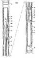
- FIG. 1Ashows an oil well 1 equipped with a bottom safety valve 2 whose hydraulic control line 3 is defective.
- Wellcomprises a production tube 4 (tubing) in communication with a Christmas tree 5.
- This safety valveis positioned in a receptacle 6 (nipple).
- a receptacle 6nipple
- the descent of the valveis done after having equipped the suspension element of the production line 10 with an adapter 12 which is used to suspend the entire system once it has fully descended into the well, to maintain the connecting elements one after the other, to allow their connection between them, to go down the whole steps after steps.
- the wellis under pressure, an airlock mounted on the Christmas tree, allows the maneuvering procedure in the well.
- the maneuvering procedureis conventionally cable ("wireline"). This procedure involves lowering the valve and connecting elements in several steps. Step 1: the valve hooked to its first rod member 14 is lowered to the maintenance of the upper part of the first element by the jaws, thereby allowing the suspension of the first element and the attachment on the adapter 12. Step 2: The standard rod member is lowered and is connected to the first element attached to the adapter 12.
- Step 3This step 3 is identical to step 2 and multiplied as many times as is necessary depending on the number of rods required given the rating valve installation.
- Last stepThis last step is to lower the last element having in its upper part the suspension head 21 and connect it to the last standard element held by the jaws. The jaws are then open allowing the descent of the complete assembly and the installation and the locking of the suspension 21 in the adapter 12.
- valve 17When a hydraulic pressure is applied in the control line 15, the different functional means of the valve 17 are activated, that is to say, the valve opens after tilting of the valve 18, the "dogs" of anchoring 19 are expanded radially to immobilize the valve body in the tube, the seal is pressed to bear against the wall of the tube and seal.
- FIG. 3shows in section more details of the constitution of the valve 17.
- the valve 18is in the closed position by the action of a spring (not shown). It is opened by the displacement of a tube 23 under the thrust action of a ring 24 connected to a piston 25.
- the pistonbears on the tube 23 by intermediate ring 24 to compress the spring 27 and to slide said tube which tilts the cover 18.
- the return spring 27pushes the tube 23 and the seal closes by securing the well.
- Anchoring wedges 19are radially displaced by a piston 28 whose end is conical on which these anchoring corners 19 rest.
- the piston 28is pushed under the corners by the hydraulic pressure in the chamber 29, the displacement of the piston blocking the corners on the wall of the tube 10.
- Locking means 30 of the position of the anchoring piston 28keeps the piston in place even when the pressure has dropped in the chamber 30.
- These locking meanscan operate according to the principle of ratchet or toothing.
- wedges 19a, piston 28a, hydraulic chamber 29a, 30a lockin the upper part of the body of the pump.
- the inventionwill not be limited to two anchor assemblies, in most embodiments only one anchor assembly is required.
- the present valvealso comprises sealing means between the body of the valve and the production tube 10.
- This assemblyis an essential element in that in case of failure the safety valve is totally inoperative and in that is difficult to seal on a raw surface as a wall of a production tube.
- These sealing meanscomprise a packing assembly 20 which is activated on the wall of the tube by a piston 31 displaced by the hydraulic pressure which is in the chamber 32. Locking means 33 hold the piston 31 in place even without pressure in room 32.
- the connector 22is connected to the surface by the rods 14 ( Figure 2B). It should be noted that the rise in hydraulic pressure in the duct 34 (about 35 MPa), transmits the pressure energy in all the chambers at the same time which achieves, substantially at the same time: the opening of the valve, its anchorage and its tightness in the tubing. When the hydraulic pressure drops in the conduit 34, the valve closes but remains in place, anchored and sealed.
- a special profile 35 located at the top of the valve bodyallows the valve body to be disengaged by traction and threshing with the help of a recovery tool adapted to this profile. Threshing on the valve body breaks a series of shear pins that release the anchoring piston or pistons 28, 28a, and the sealing piston 31. The released valve can then be raised to the surface.
- the optimized shape of the cups 38results from the general shape in so-called chevron "U” or “V”, in which the section of the cups have a symmetry along an axis parallel to the central axis (we can refer to the book Technical "Seals and Sealing Handbook" -Ed. The Trade and Technical Press Limited, 1985 ). These seals are suitable for assemblies without catch-up, or only a few tenths of a millimeter. Indeed, it has been verified that symmetrical axis section joints are not compatible with large backlash compensations, for example greater than 2.5 mm, in particular in the case of withstanding a pressure greater than 5000 PSI, that is, about 350 MPa.
- FIG. 4Bschematically illustrates the assembly of the packing once compressed by the action of the piston 41.
- the inner part of the stack cupsis sealing on the surface 43 of the stuffing box 36.
- the anti-extrusion metal cup 39is deformed to be bent on the inner wall 44 of the production tube.
- the outer lip of the cupsis raised to also rest on the tube and seal the annular space. Under pressure, according to the arrow 42, the linings bear more strongly on the tube while being held by the anti-extrusion cup.
- the optimized shape of the sealing cupscan be defined as follows: the section of the cup is V-shaped, one of the branches, the one in contact with the surface of the stuffing box (internal diameter of the cup), is shortened 47. Thus, the tip 45 of the V is no longer in the middle position of the annulus between the stuffing cylinder and the inner wall of the tube, but is shifted and closer to the stuffer.
- the branch of the V 46 which supports the most deformation, that which is on the side play j,is the longest favoring its displacement under the action of the piston.
- the shape of the end of the two branches of the asymmetrical chevronis adapted to be plated effectively on the cylindrical surfaces of the stuffing box and the production tube. It has been verified by experience and finite element calculations that this asymmetrical shape of the cups provides the most regular contact stresses and therefore a good resistance to pressure.
- HNBR rubber of hardness 80 Shore Amay be used which is also suitable for the current temperatures in the production wells.
Landscapes
- Geology (AREA)
- Life Sciences & Earth Sciences (AREA)
- Engineering & Computer Science (AREA)
- Mining & Mineral Resources (AREA)
- Environmental & Geological Engineering (AREA)
- Fluid Mechanics (AREA)
- Physics & Mathematics (AREA)
- General Life Sciences & Earth Sciences (AREA)
- Geochemistry & Mineralogy (AREA)
- Safety Valves (AREA)
- Lift Valve (AREA)
- Pipe Accessories (AREA)
- Lubricants (AREA)
Abstract
Description
Translated fromFrenchLa présente invention concerne un procédé de remise en sécurité d'un puits pétrolier équipé ou non d'une vanne de sécurité de fond défaillante.The present invention relates to a method for restoring a petroleum well with or without a defective bottom safety valve.
On sait que, pour des raisons de sécurité, les puits pétroliers sont généralement équipés de vannes de sécurité de fond qui sont, soit intercalées entre la connexion de deux éléments de tubes, soit insérées dans un réceptacle logé dans le tube de production du puits à quelques dizaines ou centaines de mètres de profondeur. Ces vannes ont pour fonction de permettre de stopper automatiquement la production d'effluent si un incident survient en tête de puits ou en aval de celles-ci. Elles sont souvent commandées depuis la surface par une pression hydraulique à l'ouverture et se ferment automatiquement au moyen d'un puissant ressort de rappel dès l'apparition d'une chute de la pression hydraulique sur la ligne de commande, que cette chute soit commandée ou accidentelle.It is known that, for reasons of safety, oil wells are generally equipped with bottom safety valves which are either inserted between the connection of two tube elements or inserted into a receptacle housed in the tube of production of the well. a few tens or hundreds of meters deep. These valves have the function of allowing to automatically stop the production of effluent if an incident occurs at the wellhead or downstream of them. They are often controlled from the surface by a hydraulic pressure at the opening and close automatically by means of a strong return spring as soon as a hydraulic pressure drop on the control line, this fall is ordered or accidental.
La ligne de commande hydraulique peut aussi présenter des défauts (fuite, ligne bouchée ou cassée), la vanne de sécurité ne peut plus alors jouer son rôle. Elle reste généralement fermée sous l'action de son ressort et obture le passage de l'effluent.The hydraulic control line may also have defects (leakage, clogged or broken line), the safety valve can no longer play its role. It remains generally closed under the action of its spring and closes the passage of the effluent.
Deux solutions s'offrent actuellement à l'exploitant pour pallier à cette déficience. Il peut extraire la vanne de sécurité du tube de production (après mise en place d'un sas en tête de puits) et fermer ensuite la ligne de commande défectueuse en mettant en place dans le tube de production une chemise d'isolation dotée de garnitures d'étanchéité qui isolent l'arrivée du fluide de commande à travers le réceptacle. Le puits peut à nouveau produire mais il se trouve alors en dehors des normes de sécurité puisqu'il n'est plus équipé d'une vanne de sécurité de fond. Une autre solution évitant ce fonctionnement hors norme consiste à "tuer" le puits, c'est-à-dire à équilibrer la pression du gisement avec une colonne hydrostatique de boue de densité adéquate, puis en intervenant dans le puits pour réparer selon les techniques de la profession. Cette solution qui permet ensuite de travailler selon les normes de sécurité, est extrêmement lourde et onéreuse.Two solutions are currently available to the operator to overcome this deficiency. It can extract the safety valve from the production tube (after setting up an airlock at the wellhead) and then close the defective control line by inserting in the production tube an insulating jacket with fittings sealing the arrival of the control fluid through the receptacle. The well can again produce but it is then outside safety standards since it is no longer equipped with a bottom safety valve. Another solution that avoids this extraordinary operation is to "kill" the well, that is to say, to balance the pressure of the deposit with a hydrostatic column of mud of adequate density, then by intervening in the well to repair according to the techniques of the profession. This solution which allows then to work according to safety standards, is extremely heavy and expensive.
On connaît, par le document
On connaît le document
La présente invention concerne une vanne de sécurité de puits comportant des perfectionnements par rapport à la vanne spéciale et les outillages tels que décrit dans le document déjà cité
Ainsi, la présente invention concerne une vanne de sécurité de puits mise en place dans un tube de production, comprenant un corps comportant des moyens d'obturation d'un passage interne au corps, des moyens d'ancrage du corps dans le tube, des moyens d'étanchéité entre le corps et la paroi du tube, la vanne comprenant des moyens de communication d'une pression hydraulique outre la vanne et la surface du puits. Selon l'invention, les moyens d'obturation, d'ancrage et d'étanchéité comportent des moyens d'activation hydraulique tels que la pression hydraulique transmise de la surface active les moyens de façon à ouvrir ledit passage, ancrer la vanne dans le tube et activer les moyens d'étanchéité sur la paroi du tube.Thus, the present invention relates to a well safety valve installed in a production tube, comprising a body having means for closing a passage internal to the body, means for anchoring the body in the tube, sealing means between the body and the wall of the tube, the valve comprising means for communicating a hydraulic pressure in addition to the valve and the surface of the well. According to the invention, the means of closing, anchoring and sealing comprise hydraulic activation means such that the hydraulic pressure transmitted from the active surface means to open said passage, anchor the valve in the tube. and activate the sealing means on the wall of the tube.
Les moyens d'étanchéité comportent un empilage de plusieurs joints annulaires en matériau résilient pouvant être comprimé par le déplacement d'une chemise de compression d'un piston hydraulique et la section des joints annulaires est en forme d'un V dont la longueur des branches est dissymétrique, la branche en contact intérieur avec le corps de la vanne étant la plus courte, la branche en contact avec la paroi du tube, après compression de l'empilage par le piston, est déformée pour entrer en contact avec la paroi du tube.The sealing means comprise a stack of several annular seals of resilient material compressible by the displacement of a compression sleeve of a hydraulic piston and the section of the annular seals is in the shape of a V whose length of the branches is asymmetrical, the branch in internal contact with the body of the valve being the shortest, the branch in contact with the wall of the tube, after compression of the stack by the piston, is deformed to come into contact with the wall of the tube.
Les moyens d'obturation peuvent comporter un clapet maintenu en position fermée par un moyen de rappel, un piston hydraulique fournissant en pression un déplacement longitudinal d'une chemise de façon à maintenir ouvert le clapet.The closure means may comprise a valve held in the closed position by a return means, a hydraulic piston providing pressure a longitudinal displacement of a jacket so as to keep the valve open.
Les moyens d'ancrage peuvent comporter des mâchoires pouvant être déplacées de façon radiale contre la paroi du tube par une chemise d'ancrage d'un piston hydraulique.The anchoring means may comprise jaws movable radially against the wall of the tube by an anchoring sleeve of a hydraulic piston.
L'ancrage peut être mécaniquement verrouillé par des moyens d'immobilisation de la chemise d'ancrage.The anchorage can be mechanically locked by means of immobilizing the anchoring liner.
L'empilage peut comporter une coupelle métallique anti extrusion dont le diamètre extérieur est environ le diamètre extérieur du corps de la vanne avant compression de l'empilage.The stack may include an anti-extrusion metal cup whose outer diameter is about the outside diameter of the valve body before the stack is compressed.
L'empilage peut être constitué de huit coupelles en V en élastomère du type HNBR de dureté shore A environ 80.The stack may consist of eight V-shaped elastomeric cups of HNBR type shore hardness A about 80.
L'empilage peut être mécaniquement maintenu comprimé par des moyens d'immobilisation de la chemise de compression.The stack can be mechanically held compressed by means of immobilizing the compression liner.
Les moyens de communication hydraulique peuvent être constitués par des éléments tubulaires assemblés entre eux par des raccords, une extrémité d'un premier élément est connectée au corps de ladite vanne, une extrémité de l'élément supérieur est connectée à un élément de suspension.The hydraulic communication means may consist of tubular elements assembled together by connectors, one end a first member is connected to the body of said valve, an end of the upper member is connected to a suspension member.
L'élément de suspension peut être maintenu dans un adapteur fixé sur la tête du puits et comportant des moyens de communication hydraulique avec lesdits éléments tubulaires.The suspension element can be held in an adapter fixed on the wellhead and having means of hydraulic communication with said tubular elements.
L'adapteur peut comporter des mâchoires à déplacement radial destinées à être serrées sur lesdits éléments tubulaires.The adapter may include radial displacement jaws for clamping on said tubular members.
L'invention concerne également une méthode de mise en place de la vanne selon l'invention dans un tube de production, dans laquelle on effectue les étapes suivantes :
- on assemble un adapteur sur la tête de puits,
- on descend la vanne dans le tube de production en assemblant un nombre d'éléments tubulaires correspondant à la cote désirée,
- on suspend la vanne et ses éléments tubulaires sur l'adapteur par l'intermédiaire d'une tête de suspension, et on connecte le conduit hydraulique desdits éléments tubulaires à une source de pression en surface,
- on met en pression la vanne pour ouvrir le passage, ancrer le corps de la vanne dans le tube à la cote où elle se trouve, comprimer l'empilage de joints pour réaliser l'étanchéité annulaire.
- we assemble an adapter on the wellhead,
- the valve is lowered into the production tube by assembling a number of tubular elements corresponding to the desired dimension,
- the valve and its tubular elements are suspended on the adapter by means of a suspension head, and the hydraulic conduit of said tubular elements is connected to a source of surface pressure,
- the valve is pressurized to open the passage, anchor the body of the valve in the tube to the dimension where it is, compress the stack of joints to achieve the annular seal.
Selon la méthode, on peut mettre en sécurité le puits en faisant chuter la pression dans la vanne pour fermer lesdits moyens d'obturation du passage sans déverrouiller l'ancrage ni désactiver l'empilage des joints d'étanchéité annulaire.According to the method, the well can be made safe by lowering the pressure in the valve to close the said closing means of the passage without unlocking the anchor or disabling the stacking of the annular seals.
On peut déconnecter et remonter les éléments tubulaires avant de descendre un outil adapté à se connecter sur la tête du corps de la vanne et à déverrouiller par battage les ancrages et les moyens de compression de l'empilage.It is possible to disconnect and reassemble the tubular elements before lowering a tool adapted to connect to the head of the valve body and to unlock by hammering the anchors and the compression means of the stack.
La présente invention sera mieux comprise et ses avantages apparaîtront plus clairement à la lecture de la description des exemples suivants, nullement limitatifs, illustrés par les figures ci-après annexées, parmi lesquelles :
- les figures 1A et 1 B montrent schématiquement une vanne selon l'art antérieur,
- les figures 2A et 2B montrent schématiquement une installation comportant une vanne selon la présente invention,
- la figure 3 montre en coupe longitudinale un mode de réalisation d'une vanne selon l'invention,
- les figures 4A et 4B montrent schématiquement le principe de l'ensemble des moyens d'étanchéité et d'ancrage de la vanne selon l'invention.
- FIGS. 1A and 1B schematically show a valve according to the prior art,
- FIGS. 2A and 2B schematically show an installation comprising a valve according to the present invention,
- FIG. 3 shows in longitudinal section an embodiment of a valve according to the invention,
- FIGS. 4A and 4B schematically show the principle of all the sealing and anchoring means of the valve according to the invention.
La figure 1A montre un puits pétrolier 1 équipé d'une vanne de sécurité de fond 2 dont la ligne de commande hydraulique 3 est défectueuse. Le puits comporte un tube de production 4 (tubing) en communication avec un arbre de noël 5. Cette vanne de sécurité est positionnée dans un réceptacle 6 (nipple). Pour réparer et remettre en conformité le puits, il faut enlever la vanne de son siège pour installer une nouvelle vanne qui permettra de rétablir la production dans les plus brefs délais, et en toute sécurité. Dans le cas où la ligne de contrôle ne peut plus être opérationnelle, on peut installer une vanne de sécurité dans le siège ou réceptacle 6, vanne telle que décrite dans le document
La figure 1B montre cette vanne constituée de trois principaux ensembles :
- l'ensemble d'obturation 7, ou vanne proprement dite, commandé par pression hydraulique,
- l'ensemble de brides d'adaptation et de
liaison 8, - et l'ensemble des
lignes 9 de liaison entre cet « adapter » 8 et lavanne 7.
- the
shutter assembly 7, or valve itself, controlled by hydraulic pressure, - the set of adaptation and
connection flanges 8, - and all the
lines 9 connecting this "adapter" 8 and thevalve 7.
Le détail de ces équipements et des procédures de mise en place ou d'opérations sont clairement décrits dans le document cité plus haut. Compte tenu de la longueur fixée entre le réceptacle et la position de l'élément d'adaptation 8, le nombre de tiges 9 et leur longueur totale doivent être déterminés en fonction du puits en question.The details of this equipment and the procedures for implementation or operations are clearly described in the document cited above. Given the fixed length between the receptacle and the position of the
La figure 2A montre un puits 11 comportant un tube de production 10 de diamètre intérieur connu. Dans le cas où il s'avère nécessaire d'ajouter une vanne de sécurité à l'intérieur de ce tube, on peut utiliser avantageusement le système selon l'invention, représenté schématiquement sur la figure 2B. Un adaptateur 12 est intercalé entre les vannes maîtresses 13 et la suspension du tube de production (tubing hanger). Ce dispositif est similaire à celui décrit dans le document
- des moyens d'obturation 18 du canal intérieur du corps de la vanne;
- des moyens d'ancrage 19 de la vanne 17 dans l'intérieur du
tube de production 10 ; - des moyens d'étanchéité 20 entre le corps de la vanne et l'intérieur du
tube 10.
- closure means 18 of the inner channel of the valve body;
- anchoring means 19 of the
valve 17 in the interior of theproduction tube 10; - sealing means 20 between the body of the valve and the inside of the
tube 10.
Dans une variante, il y a deux étages d'ancrage, dans une autre variante, un seul étage est nécessaire.In a variant, there are two anchoring stages, in another variant, only one stage is necessary.
La descente de la vanne se fait après avoir équipé l'élément de suspension de la conduite de production 10 d'un adaptateur 12 qui est utilisé pour suspendre l'ensemble du système une fois celui-ci entièrement descendu dans le puits, pour maintenir les éléments de connexion les uns après les autres, pour permettre leur connexion entre eux, pour descendre l'ensemble étapes après étapes. Le puits étant en pression, un sas monté sur l'arbre de noël, permet la procédure de manoeuvre dans le puits. La procédure de manoeuvre se fait conventionnellement au câble (« wireline »). Cette procédure consiste à descendre la vanne et les éléments de connexion en plusieurs étapes.Etape 1 : la vanne accrochée à son premier élément de tiges 14 est descendue jusqu'au maintien de la partie supérieure du premier élément par les mâchoires, permettant ainsi la suspension et l'accrochage du premier élément sur l'adaptateur 12 .Etape 2 : L'élément de tige standard est descendu et est connecté au premier élément accroché à l'adaptateur 12. Les mâchoires de maintien sont ensuite ouvertes pour permettre la descente du premier élément accroché au deuxième élément de tige jusqu'au maintien de la partie supérieure de l'élément standard par les mâchoires, permettant ainsi la suspension et l'accrochage de ses deux éléments sur l'adaptateur 12.Etape 3. Cette étape 3 est identique à l'étape 2 et multipliée autant de fois qu'il est nécessaire en fonction du nombre de tiges nécessaire compte tenu de la cote d'installation de la vanne.Dernière étape : Cette dernière étape consiste à descendre le dernier élément comportant dans sa partie haute la tête de suspension 21 et à le connecter sur le dernier élément standard maintenu par les mâchoires. Les mâchoires sont ensuite ouvertes permettant la descente de l'ensemble complet et la pose ainsi que le verrouillage de la suspension 21 dans l'adaptateur 12.The descent of the valve is done after having equipped the suspension element of the
Lorsque l'on applique une pression hydraulique dans la ligne de contrôle 15, on active les différents moyens fonctionnels de la vanne 17, c'est à dire, la vanne s'ouvre après basculement du clapet 18, les « chiens » d'ancrage 19 sont expansés de façon radiale pour immobiliser le corps de la vanne dans le tube, la garniture d'étanchéité est comprimée pour s'appuyer sur la paroi du tube et effectuer une étanchéité.When a hydraulic pressure is applied in the
La figure 3 montre en coupe plus de détails de la constitution de la vanne 17. Le clapet 18 est en position fermée grâce à l'action d'un ressort (non représenté). Il est ouvert par le déplacement d'un tube 23 sous l'action de poussée d'un anneau 24 lié à un piston 25. En présence d'une pression hydraulique suffisante dans la chambre 26, le piston appuie sur le tube 23 par l'intermédiaire de l'anneau 24 jusqu'à comprimer le ressort 27 et à faire coulisser ledit tube qui fait basculer l'opercule 18. En absence de pression dans la chambre 26, le ressort de rappel 27 repousse le tube 23 et l'opercule se ferme en mettant en sécurité le puits.Figure 3 shows in section more details of the constitution of the
Des coins d'ancrage 19 sont déplacés de façon radiale par un piston 28 dont l'extrémité est en forme de cône sur laquelle s'appuient lesdits coins d'ancrage 19. Le piston 28 est poussé sous les coins par la pression hydraulique dans la chambre 29, le déplacement du piston bloquant les coins sur la paroi du tube 10. Des moyens de verrouillage 30 de la position du piston d'ancrage 28 permet de maintenir en place ce piston même lorsque la pression a chutée dans la chambre 30. Ces moyens de verrouillage peuvent fonctionner selon le principe de cliquet ou de denture. Sur la figure 3, on retrouve un second ensemble : coins 19a, piston 28a, chambre hydraulique 29a, verrouillage 30a, dans la partie supérieure du corps de la pompe. Cependant, l'invention ne se limitera pas à deux ensembles d'ancrage, dans la plupart des réalisations un seul ensemble d'ancrage est nécessaire.Anchoring
La présente vanne comprend également des moyens d'étanchéité entre le corps de la vanne et le tube de production 10. Cet ensemble est un élément essentiel en ce qu'en cas de défaillance la vanne de sécurité est totalement inopérante et en ce qu'il est délicat de faire une étanchéité sur une surface brute comme une paroi d'un tube de production. Ces moyens d'étanchéité comprennent un ensemble de garniture 20 qui est activé sur la paroi du tube par un piston 31 déplacé par la pression hydraulique qui se trouve dans la chambre 32. Des moyens de verrouillage 33 maintiennent le piston 31 en place même sans pression dans la chambre 32.The present valve also comprises sealing means between the body of the valve and the
Un conduit 34 en communication avec un connecteur 22, distribue la pression hydraulique dans les chambres décrites ci-dessus : la chambre d'ouverture de la vanne 26, la ou les chambres d'ancrage 29 et 29a, la chambre des moyens d'étanchéité 32. Le connecteur 22 est relié à la surface par les tiges 14 (figure 2B). Il faut noter que la montée en pression hydraulique dans le conduit 34 (environ 35 MPa), transmet l'énergie de pression dans toutes les chambres à la fois ce qui réalise, sensiblement dans le même temps: l'ouverture de la vanne, son ancrage et son étanchéité dans le tubing. Lorsque la pression hydraulique chute dans le conduit 34, la vanne se ferme mais reste en place, ancrée et étanche. Un profil spécial 35 situé en tête du corps de la vanne permet de désancrer le corps de vanne par traction et battage à l'aide d'un outil de repêchage adapté à ce profil. Par battage sur le corps de la vanne, on casse une série de goupilles de cisaillement qui libèrent le ou les pistons d'ancrage 28, 28a, ainsi que le piston d'étanchéité 31. La vanne libérée peut être alors remontée en surface.A
Les figures 4A et 4B illustrent schématiquement le principe de l'ensemble de garniture 20 des moyens d'étanchéités entre le corps porte garniture 36 et le tube de production 10. La référence (j) désigne le jeu radial entre le diamètre extérieur des garniture d'étanchéité 37 et le diamètre intérieur du tube. Ce jeu est généralement de l'ordre de 2,5 mm, mais peut atteindre 5 mm. La garniture est constituée d'un empilage de huit coupelles 38 de forme optimisée pour résister à la pression après avoir été déformées contre la paroi du tube. La pièce 40 constitue l'appui sur lequel est comprimé, selon un effort axial, l'empilage des coupelles 38. La pièce 41 désigne le nez du piston (référencé 31 sur la figure 3). Une coupelle anti extrusion 39 est intercalée entre la première coupelle et le nez du piston 41. Il faut noter que la pression du puits s'applique dans le sens de la flèche référencée 42.FIGS. 4A and 4B schematically illustrate the principle of the packing
La forme optimisée des coupelles 38 résulte de la forme générale en chevron dits en « U » ou « V », dans laquelle la section des coupelles présentent une symétrie selon un axe parallèle à l'axe central (on pourra se référer à l'ouvrage technique :
Pour qu'une garniture d'étanchéité puisse rattraper un jeu de quelques millimètres, on a déterminé qu'il faut optimiser notamment : la capacité de déformation du matériau, la tenue à la pression de ce même matériau, le niveau des frictions sur le porte garniture de façon que les déformations nécessaires soient obtenues avec de moindres efforts.In order for a seal to catch up to a few millimeters, it has been determined that it is necessary to optimize in particular: the deformation capacity of the material, the resistance to the pressure of the same material, the level of friction on the door trim so that the necessary deformations are obtained with less effort.
La figure 4B illustre de façon schématique l'ensemble de la garniture une fois comprimé par l'action du piston 41. La partie intérieure de l'empilage des coupelles fait étanchéité sur la surface 43 du porte-garniture 36. La coupelle métallique anti extrusion 39 se déforme pour s'arc-bouter sur la paroi interne 44 du tube de production. La lèvre externe des coupelles est relevée pour également s'appuyer sur le tube et obturer l'espace annulaire. En pression, selon la flèche 42, les garnitures s'appuient plus fortement sur le tube tout en étant maintenues par la coupelle anti extrusion.FIG. 4B schematically illustrates the assembly of the packing once compressed by the action of the
La forme optimisée des coupelles d'étanchéité peut être définie ainsi : la section de la coupelle est en forme de V dont une des branches, celle au contact avec la surface du porte-garniture (diamètre intérieur de la coupelle), est raccourcie 47. Ainsi, la pointe 45 du V ne se trouve plus dans la position médiane de l'espace annulaire entre le cylindre porte-garniture et la paroi intérieure du tube, mais est décalée et plus proche du porte-garniture. La branche du V 46 qui supporte le plus de déformation, celle qui se trouve du coté jeu j, est la plus longue favorisant son déplacement sous l'action du piston. La forme de l'extrémité des deux branches du chevron dissymétrique est adaptée à se plaquer efficacement sur les surfaces cylindriques du porte-garniture et du tube de production. On a vérifié par expérience et calculs aux éléments finis que cette forme dissymétrique des coupelles fournit des contraintes de contact les plus régulières et donc une bonne tenue à la pression.The optimized shape of the sealing cups can be defined as follows: the section of the cup is V-shaped, one of the branches, the one in contact with the surface of the stuffing box (internal diameter of the cup), is shortened 47. Thus, the
Comme matériau, on pourra utiliser du caoutchouc HNBR de dureté 80 Shore A qui convient également pour les températures courantes dans les puits de production.As a material, HNBR rubber of hardness 80 Shore A may be used which is also suitable for the current temperatures in the production wells.
Selon l'invention, le nombre de coupelles est choisi à huit dans le cas d'une vanne adaptée à être descendue dans un tube d'environ 75 à 80 mm de diamètre intérieur. L'invention ne se limite pas à ce nombre de coupelles qui peut varier en fonction de la pression de service et/ou la nature des fluides.According to the invention, the number of cups is chosen at eight in the case of a valve adapted to be lowered into a tube of about 75 to 80 mm internal diameter. The invention is not limited to this number of cups which can vary depending on the operating pressure and / or the nature of the fluids.
Claims (10)
- A well safety valve placed in a production tubing (10), including a body (17) comprising shutoff means (18) for shutting off an inner passage of said body, anchoring means (19) for anchoring said body in said tubing, sealing means (20) between said body and the wall of the tubing, said valve including means (14) for communicating a hydraulic pressure between said valve and the surface of the well, wherein said shutoff, anchoring and sealing means comprise hydraulic activation means (25, 28, 31) such that said hydraulic pressure transmitted from the surface activates said means so as to open said passage, anchor the valve in the tubing and activate the sealing means on the tubing wall,characterised in that said sealing means comprise a pile of several ring-type joints (38) made of a resilient material that can be compressed by displacement of a compression sleeve (41) of a hydraulic piston and in which the section of said ring-type joints has the shape of a V with an unsymmetrical length of the branches thereof, the branch in inner contact (47) with the valve body being the shorter, branch (46) in contact with the tubing wall, after the pile is compressed by the piston, is deformed to come into contact with the tubing wall.
- The valve according to Claim 1, in which said shutoff means comprise a shutoff valve (18) held in closed position by a return means (27), a hydraulic piston (26) providing, under pressure, longitudinal displacement of a sleeve (23) so as to keep said shutoff valve open.
- The valve according to claim 1 or 2, in which said anchoring means comprise grips (19) that can be displaced radially against the tubing wall by an anchoring sleeve (28a) of a hydraulic piston (29a).
- The valve according to claim 3, in which anchoring is mechanically locked by means (30a) for immobilizing the anchoring sleeve.
- The valve according to one of claims 1 or 4, in which said pile comprises a metal anti-extrusion cup (39) of which the outer diameter is approximately the outer diameter of the valve body before the pile is compressed.
- The valve according to one of claims 1 to 5, in which said pile consists of eight V-shaped cups (38) made of HNBR-type elastomer with an A Shore hardness of approximately 80.
- The valve according to claim 1 to 6, in which the pile is mechanically held compressed by means for immobilizing the compression sleeve.
- The valve according to one of the prececeding claims, in which the hydraulic communication means consist of tubular elements put together by means of connections, one end of a first element is connected to the body of said valve, one end of the upper element is connected to a hanger element.
- The valve according to Claim 8, in which the hanger element is held in an adapter (12) fastened to the wellhead and comprising means for hydraulic communication with said tubular elements.
- The valve according to Claim 9, in which said adapter comprises radial-displacement grips (51 a, 51 b) intended to grip said tubular elements.
Applications Claiming Priority (3)
| Application Number | Priority Date | Filing Date | Title |
|---|---|---|---|
| FR0101390AFR2820457B1 (en) | 2001-02-02 | 2001-02-02 | SAFETY VALVE WITH DIRECT INSTALLATION IN A TUBE FOR PRODUCING AN OIL WELL AND METHOD FOR IMPLEMENTING SAME |
| FR0101390 | 2001-02-02 | ||
| PCT/FR2002/000155WO2002063129A1 (en) | 2001-02-02 | 2002-01-16 | Safety valve for oil wells |
Publications (2)
| Publication Number | Publication Date |
|---|---|
| EP1360392A1 EP1360392A1 (en) | 2003-11-12 |
| EP1360392B1true EP1360392B1 (en) | 2007-08-01 |
Family
ID=8859522
Family Applications (1)
| Application Number | Title | Priority Date | Filing Date |
|---|---|---|---|
| EP02711970AExpired - LifetimeEP1360392B1 (en) | 2001-02-02 | 2002-01-16 | Safety valve for oil wells |
Country Status (6)
| Country | Link |
|---|---|
| US (1) | US7040409B2 (en) |
| EP (1) | EP1360392B1 (en) |
| AT (1) | ATE368796T1 (en) |
| DE (1) | DE60221499D1 (en) |
| FR (1) | FR2820457B1 (en) |
| WO (1) | WO2002063129A1 (en) |
Families Citing this family (14)
| Publication number | Priority date | Publication date | Assignee | Title |
|---|---|---|---|---|
| US7255174B2 (en)* | 2003-07-16 | 2007-08-14 | Baker Hughes Incorporated | Cement control ring |
| WO2006034214A2 (en)* | 2004-09-20 | 2006-03-30 | Bj Services Company | Downhole safety valve apparatus and method |
| FR2890099B1 (en)* | 2005-08-30 | 2007-11-30 | Geoservices | SAFETY DEVICE FOR AN OIL WELL AND ASSOCIATED SECURITY INSTALLATION. |
| US20080230236A1 (en)* | 2007-03-21 | 2008-09-25 | Marie Wright | Packing element and method |
| US7758019B2 (en)* | 2007-04-12 | 2010-07-20 | Tiw Corporation | Safety valve |
| US20090205832A1 (en)* | 2008-02-14 | 2009-08-20 | Weatherford/Lamb, Inc. | Apparatus to clear control line in well |
| US7775291B2 (en)* | 2008-05-29 | 2010-08-17 | Weatherford/Lamb, Inc. | Retrievable surface controlled subsurface safety valve |
| US8100181B2 (en) | 2008-05-29 | 2012-01-24 | Weatherford/Lamb, Inc. | Surface controlled subsurface safety valve having integral pack-off |
| CA2696583C (en) | 2009-03-20 | 2013-02-26 | Weatherford/Lamb, Inc. | Capillary hanger arrangement for deploying control line in existing wellhead |
| US8479828B2 (en) | 2010-05-13 | 2013-07-09 | Weatherford/Lamb, Inc. | Wellhead control line deployment |
| GB2513846A (en)* | 2013-05-03 | 2014-11-12 | Rubberatkins Ltd | Downhole seal |
| GB2513847A (en)* | 2013-05-03 | 2014-11-12 | Rubberatkins Ltd | Seal Assembly |
| WO2017204804A1 (en)* | 2016-05-26 | 2017-11-30 | Halliburton Energy Services, Inc. | Hydraulically controlled electric insert safety valve |
| US11578561B2 (en)* | 2020-10-07 | 2023-02-14 | Weatherford Technology Holdings, Llc | Stinger for actuating surface-controlled subsurface safety valve |
Family Cites Families (10)
| Publication number | Priority date | Publication date | Assignee | Title |
|---|---|---|---|---|
| US3910352A (en)* | 1972-09-25 | 1975-10-07 | Hydril Co | In-tubing safety valve well tool |
| US4288082A (en)* | 1980-04-30 | 1981-09-08 | Otis Engineering Corporation | Well sealing system |
| US4691776A (en)* | 1986-05-29 | 1987-09-08 | Camco, Incorporated | Retrievable well safety valve with expandable external seals |
| US5094294A (en)* | 1987-03-30 | 1992-03-10 | Otis Engineering Corp. | Well pump assembly and packer |
| US5361834A (en)* | 1992-09-04 | 1994-11-08 | Halliburton Company | Hydraulic release apparatus and method for retrieving a stuck downhole tool and moving a downhole tool longitudinally |
| US5305828A (en)* | 1993-04-26 | 1994-04-26 | Halliburton Company | Combination packer/safety valve assembly for gas storage wells |
| FR2734863B1 (en) | 1995-05-30 | 1997-08-29 | Pyreneenne De Metallurg Scop S | PROCESS AND MEANS FOR THE SECURITY OF AN OIL WELL IN THE EVENT OF A DEFECT IN THE HYDRAULIC CONTROL LINE OF ITS DOWNHOLE SAFETY VALVE |
| US5857520A (en)* | 1996-11-14 | 1999-01-12 | Halliburton Energy Services, Inc. | Backup shoe for well packer |
| US5865255A (en)* | 1997-02-11 | 1999-02-02 | Halliburton Energy Services, Inc. | Full bore nipple and associated lock mandrel therefor |
| US6202747B1 (en)* | 1998-09-02 | 2001-03-20 | Schlumberger Technology Corporation | Hydraulic well packer and method |
- 2001
- 2001-02-02FRFR0101390Apatent/FR2820457B1/ennot_activeExpired - Fee Related
- 2002
- 2002-01-16ATAT02711970Tpatent/ATE368796T1/ennot_activeIP Right Cessation
- 2002-01-16EPEP02711970Apatent/EP1360392B1/ennot_activeExpired - Lifetime
- 2002-01-16WOPCT/FR2002/000155patent/WO2002063129A1/enactiveIP Right Grant
- 2002-01-16DEDE60221499Tpatent/DE60221499D1/ennot_activeExpired - Lifetime
- 2002-01-16USUS10/466,484patent/US7040409B2/ennot_activeExpired - Fee Related
Also Published As
| Publication number | Publication date |
|---|---|
| FR2820457B1 (en) | 2003-08-01 |
| US20040045722A1 (en) | 2004-03-11 |
| EP1360392A1 (en) | 2003-11-12 |
| FR2820457A1 (en) | 2002-08-09 |
| DE60221499D1 (en) | 2007-09-13 |
| ATE368796T1 (en) | 2007-08-15 |
| US7040409B2 (en) | 2006-05-09 |
| WO2002063129A1 (en) | 2002-08-15 |
Similar Documents
| Publication | Publication Date | Title |
|---|---|---|
| EP1360392B1 (en) | Safety valve for oil wells | |
| FR2782117A1 (en) | Connector for tying back a riser from a platform to a subsea wellhead housing has load transfer part of latch moving radially out to engage internal groove in wellhead | |
| FR2712024A1 (en) | Completion system with production tube, flexible hose. | |
| FR2519688A1 (en) | SEALING SYSTEM FOR DRILLING WELLS IN WHICH CIRCULATES A HOT FLUID | |
| FR2717532A1 (en) | Tube suspension element incorporating a seal. | |
| FR2653199A1 (en) | FLUID FLOW CONTROL VALVE IN A FLUID TRANSPORT DUCT IN A UNDERGROUND WELL AND METHOD FOR OPERATING A WELL BOTTOM VALVE. | |
| FR2740508A1 (en) | REALIZER STABILIZER FOR DRILLING A PETROLEUM WELL | |
| FR2716949A1 (en) | Tube suspension element. | |
| FR2493909A1 (en) | WELL OPERATING APPARATUS INCORPORATING A SET OF UNDERGROUND SAFETY VALVES HAVING A HYDRAULIC SEAL | |
| FR2958966A1 (en) | METHOD AND DEVICE FOR SEALING A WELL USING AN EXPANDABLE PLUG, PLUG FOR CARRYING OUT THE METHOD, AND EXTRACTOR TOOL FOR REMOVING IT | |
| FR2520829A1 (en) | METAL TO METAL JOINT | |
| FR2716930A1 (en) | Ring control valve, able to be positioned in a flexible production tube. | |
| FR2537237A1 (en) | JOINT FOR CLOSING ANNULAR SPACE | |
| FR2730004A1 (en) | DOWNHOLE TOOL | |
| FR2560632A1 (en) | APPARATUS FOR SETTING TOOLS FOR DRILLING, COMPLETING OR RECONDITIONING WELLS AND APPARATUS FOR A FAT VALVE | |
| FR2497538A1 (en) | SAFETY VALVE SYSTEM COMPRISING A REMOVABLE PRESSURE EQUALIZING SHUTTER | |
| CA2885071A1 (en) | Rotation lock torque anchor for a well production column, pump and rotation lock system, and pumping facility equipped with such a torque anchor | |
| EP0321610B1 (en) | Oil well safety valve and setting and retrieving tools for such a valve | |
| EP3092368B1 (en) | Insulation device for a well | |
| WO2017009463A1 (en) | Device for protecting a degradable rupture pin for an insulating system in an annular barrier | |
| WO2017009460A1 (en) | Well insulating device having a rupture disc | |
| FR2558520A1 (en) | METHOD AND DEVICE FOR INSTALLING SEAL LININGS IN A WELL | |
| FR2536783A1 (en) | SAFETY VALVE FOR OIL WELLS | |
| FR2666373A1 (en) | SHUTTERING APPARATUS AND COLUMN SUSPENSION DEVICE. | |
| FR2521635A1 (en) | SEAT AND APPARATUS FOR COLUMN SUSPENSION DEVICE, AND METHOD FOR COMPLETING SUBMARINE WELL |
Legal Events
| Date | Code | Title | Description |
|---|---|---|---|
| PUAI | Public reference made under article 153(3) epc to a published international application that has entered the european phase | Free format text:ORIGINAL CODE: 0009012 | |
| 17P | Request for examination filed | Effective date:20030902 | |
| AK | Designated contracting states | Kind code of ref document:A1 Designated state(s):AT BE CH CY DE DK ES FI FR GB GR IE IT LI LU MC NL PT SE TR | |
| AX | Request for extension of the european patent | Extension state:AL LT LV MK RO SI | |
| 17Q | First examination report despatched | Effective date:20060721 | |
| GRAP | Despatch of communication of intention to grant a patent | Free format text:ORIGINAL CODE: EPIDOSNIGR1 | |
| GRAS | Grant fee paid | Free format text:ORIGINAL CODE: EPIDOSNIGR3 | |
| GRAA | (expected) grant | Free format text:ORIGINAL CODE: 0009210 | |
| AK | Designated contracting states | Kind code of ref document:B1 Designated state(s):AT BE CH CY DE DK ES FI FR GB GR IE IT LI LU MC NL PT SE TR | |
| REG | Reference to a national code | Ref country code:GB Ref legal event code:FG4D Free format text:NOT ENGLISH | |
| REG | Reference to a national code | Ref country code:CH Ref legal event code:EP | |
| REG | Reference to a national code | Ref country code:IE Ref legal event code:FG4D Free format text:LANGUAGE OF EP DOCUMENT: FRENCH | |
| REF | Corresponds to: | Ref document number:60221499 Country of ref document:DE Date of ref document:20070913 Kind code of ref document:P | |
| GBT | Gb: translation of ep patent filed (gb section 77(6)(a)/1977) | Effective date:20071101 | |
| PG25 | Lapsed in a contracting state [announced via postgrant information from national office to epo] | Ref country code:NL Free format text:LAPSE BECAUSE OF FAILURE TO SUBMIT A TRANSLATION OF THE DESCRIPTION OR TO PAY THE FEE WITHIN THE PRESCRIBED TIME-LIMIT Effective date:20070801 Ref country code:FI Free format text:LAPSE BECAUSE OF FAILURE TO SUBMIT A TRANSLATION OF THE DESCRIPTION OR TO PAY THE FEE WITHIN THE PRESCRIBED TIME-LIMIT Effective date:20070801 Ref country code:ES Free format text:LAPSE BECAUSE OF FAILURE TO SUBMIT A TRANSLATION OF THE DESCRIPTION OR TO PAY THE FEE WITHIN THE PRESCRIBED TIME-LIMIT Effective date:20071112 | |
| NLV1 | Nl: lapsed or annulled due to failure to fulfill the requirements of art. 29p and 29m of the patents act | ||
| PG25 | Lapsed in a contracting state [announced via postgrant information from national office to epo] | Ref country code:AT Free format text:LAPSE BECAUSE OF FAILURE TO SUBMIT A TRANSLATION OF THE DESCRIPTION OR TO PAY THE FEE WITHIN THE PRESCRIBED TIME-LIMIT Effective date:20070801 | |
| REG | Reference to a national code | Ref country code:IE Ref legal event code:FD4D | |
| PG25 | Lapsed in a contracting state [announced via postgrant information from national office to epo] | Ref country code:DK Free format text:LAPSE BECAUSE OF FAILURE TO SUBMIT A TRANSLATION OF THE DESCRIPTION OR TO PAY THE FEE WITHIN THE PRESCRIBED TIME-LIMIT Effective date:20070801 Ref country code:GR Free format text:LAPSE BECAUSE OF FAILURE TO SUBMIT A TRANSLATION OF THE DESCRIPTION OR TO PAY THE FEE WITHIN THE PRESCRIBED TIME-LIMIT Effective date:20071102 | |
| PG25 | Lapsed in a contracting state [announced via postgrant information from national office to epo] | Ref country code:PT Free format text:LAPSE BECAUSE OF FAILURE TO SUBMIT A TRANSLATION OF THE DESCRIPTION OR TO PAY THE FEE WITHIN THE PRESCRIBED TIME-LIMIT Effective date:20080102 Ref country code:IE Free format text:LAPSE BECAUSE OF FAILURE TO SUBMIT A TRANSLATION OF THE DESCRIPTION OR TO PAY THE FEE WITHIN THE PRESCRIBED TIME-LIMIT Effective date:20070801 | |
| PLBE | No opposition filed within time limit | Free format text:ORIGINAL CODE: 0009261 | |
| STAA | Information on the status of an ep patent application or granted ep patent | Free format text:STATUS: NO OPPOSITION FILED WITHIN TIME LIMIT | |
| PG25 | Lapsed in a contracting state [announced via postgrant information from national office to epo] | Ref country code:SE Free format text:LAPSE BECAUSE OF FAILURE TO SUBMIT A TRANSLATION OF THE DESCRIPTION OR TO PAY THE FEE WITHIN THE PRESCRIBED TIME-LIMIT Effective date:20071101 | |
| 26N | No opposition filed | Effective date:20080506 | |
| BERE | Be: lapsed | Owner name:INSTITUT FRANCAIS DU PETROLE Effective date:20080131 Owner name:SOC. PYRENEENNE DE METALLURGIE Effective date:20080131 | |
| PG25 | Lapsed in a contracting state [announced via postgrant information from national office to epo] | Ref country code:DE Free format text:LAPSE BECAUSE OF FAILURE TO SUBMIT A TRANSLATION OF THE DESCRIPTION OR TO PAY THE FEE WITHIN THE PRESCRIBED TIME-LIMIT Effective date:20071103 | |
| PG25 | Lapsed in a contracting state [announced via postgrant information from national office to epo] | Ref country code:MC Free format text:LAPSE BECAUSE OF NON-PAYMENT OF DUE FEES Effective date:20080131 | |
| REG | Reference to a national code | Ref country code:CH Ref legal event code:PL | |
| PG25 | Lapsed in a contracting state [announced via postgrant information from national office to epo] | Ref country code:CH Free format text:LAPSE BECAUSE OF NON-PAYMENT OF DUE FEES Effective date:20080131 Ref country code:LI Free format text:LAPSE BECAUSE OF NON-PAYMENT OF DUE FEES Effective date:20080131 | |
| PG25 | Lapsed in a contracting state [announced via postgrant information from national office to epo] | Ref country code:BE Free format text:LAPSE BECAUSE OF NON-PAYMENT OF DUE FEES Effective date:20080131 | |
| PG25 | Lapsed in a contracting state [announced via postgrant information from national office to epo] | Ref country code:CY Free format text:LAPSE BECAUSE OF FAILURE TO SUBMIT A TRANSLATION OF THE DESCRIPTION OR TO PAY THE FEE WITHIN THE PRESCRIBED TIME-LIMIT Effective date:20070801 | |
| PGFP | Annual fee paid to national office [announced via postgrant information from national office to epo] | Ref country code:FR Payment date:20100217 Year of fee payment:9 | |
| PGFP | Annual fee paid to national office [announced via postgrant information from national office to epo] | Ref country code:GB Payment date:20100121 Year of fee payment:9 | |
| PG25 | Lapsed in a contracting state [announced via postgrant information from national office to epo] | Ref country code:LU Free format text:LAPSE BECAUSE OF NON-PAYMENT OF DUE FEES Effective date:20080116 | |
| PG25 | Lapsed in a contracting state [announced via postgrant information from national office to epo] | Ref country code:TR Free format text:LAPSE BECAUSE OF FAILURE TO SUBMIT A TRANSLATION OF THE DESCRIPTION OR TO PAY THE FEE WITHIN THE PRESCRIBED TIME-LIMIT Effective date:20070801 | |
| REG | Reference to a national code | Ref country code:FR Ref legal event code:CD | |
| PG25 | Lapsed in a contracting state [announced via postgrant information from national office to epo] | Ref country code:IT Free format text:LAPSE BECAUSE OF NON-PAYMENT OF DUE FEES Effective date:20080131 | |
| GBPC | Gb: european patent ceased through non-payment of renewal fee | Effective date:20110116 | |
| REG | Reference to a national code | Ref country code:FR Ref legal event code:ST Effective date:20110930 | |
| PG25 | Lapsed in a contracting state [announced via postgrant information from national office to epo] | Ref country code:FR Free format text:LAPSE BECAUSE OF NON-PAYMENT OF DUE FEES Effective date:20110131 | |
| PG25 | Lapsed in a contracting state [announced via postgrant information from national office to epo] | Ref country code:GB Free format text:LAPSE BECAUSE OF NON-PAYMENT OF DUE FEES Effective date:20110116 |