EP1359967B1 - Devices, systems and methods for acute or chronic delivery of substances or apparatus to extravascular treatment sites - Google Patents
Devices, systems and methods for acute or chronic delivery of substances or apparatus to extravascular treatment sitesDownload PDFInfo
- Publication number
- EP1359967B1 EP1359967B1EP02718838AEP02718838AEP1359967B1EP 1359967 B1EP1359967 B1EP 1359967B1EP 02718838 AEP02718838 AEP 02718838AEP 02718838 AEP02718838 AEP 02718838AEP 1359967 B1EP1359967 B1EP 1359967B1
- Authority
- EP
- European Patent Office
- Prior art keywords
- delivery catheter
- catheter
- substance
- lumen
- tube
- Prior art date
- Legal status (The legal status is an assumption and is not a legal conclusion. Google has not performed a legal analysis and makes no representation as to the accuracy of the status listed.)
- Expired - Lifetime
Links
Images


Classifications
- A—HUMAN NECESSITIES
- A61—MEDICAL OR VETERINARY SCIENCE; HYGIENE
- A61M—DEVICES FOR INTRODUCING MEDIA INTO, OR ONTO, THE BODY; DEVICES FOR TRANSDUCING BODY MEDIA OR FOR TAKING MEDIA FROM THE BODY; DEVICES FOR PRODUCING OR ENDING SLEEP OR STUPOR
- A61M25/00—Catheters; Hollow probes
- A61M25/01—Introducing, guiding, advancing, emplacing or holding catheters
- A61M25/06—Body-piercing guide needles or the like
- A61M25/065—Guide needles
- A—HUMAN NECESSITIES
- A61—MEDICAL OR VETERINARY SCIENCE; HYGIENE
- A61B—DIAGNOSIS; SURGERY; IDENTIFICATION
- A61B17/00—Surgical instruments, devices or methods
- A61B17/12—Surgical instruments, devices or methods for ligaturing or otherwise compressing tubular parts of the body, e.g. blood vessels or umbilical cord
- A61B17/12022—Occluding by internal devices, e.g. balloons or releasable wires
- A61B17/12099—Occluding by internal devices, e.g. balloons or releasable wires characterised by the location of the occluder
- A61B17/12109—Occluding by internal devices, e.g. balloons or releasable wires characterised by the location of the occluder in a blood vessel
- A—HUMAN NECESSITIES
- A61—MEDICAL OR VETERINARY SCIENCE; HYGIENE
- A61B—DIAGNOSIS; SURGERY; IDENTIFICATION
- A61B17/00—Surgical instruments, devices or methods
- A61B17/12—Surgical instruments, devices or methods for ligaturing or otherwise compressing tubular parts of the body, e.g. blood vessels or umbilical cord
- A61B17/12022—Occluding by internal devices, e.g. balloons or releasable wires
- A61B17/12099—Occluding by internal devices, e.g. balloons or releasable wires characterised by the location of the occluder
- A61B17/12122—Occluding by internal devices, e.g. balloons or releasable wires characterised by the location of the occluder within the heart
- A—HUMAN NECESSITIES
- A61—MEDICAL OR VETERINARY SCIENCE; HYGIENE
- A61B—DIAGNOSIS; SURGERY; IDENTIFICATION
- A61B17/00—Surgical instruments, devices or methods
- A61B17/12—Surgical instruments, devices or methods for ligaturing or otherwise compressing tubular parts of the body, e.g. blood vessels or umbilical cord
- A61B17/12022—Occluding by internal devices, e.g. balloons or releasable wires
- A61B17/12131—Occluding by internal devices, e.g. balloons or releasable wires characterised by the type of occluding device
- A61B17/12136—Balloons
- A—HUMAN NECESSITIES
- A61—MEDICAL OR VETERINARY SCIENCE; HYGIENE
- A61B—DIAGNOSIS; SURGERY; IDENTIFICATION
- A61B17/00—Surgical instruments, devices or methods
- A61B17/12—Surgical instruments, devices or methods for ligaturing or otherwise compressing tubular parts of the body, e.g. blood vessels or umbilical cord
- A61B17/12022—Occluding by internal devices, e.g. balloons or releasable wires
- A61B17/12131—Occluding by internal devices, e.g. balloons or releasable wires characterised by the type of occluding device
- A61B17/12181—Occluding by internal devices, e.g. balloons or releasable wires characterised by the type of occluding device formed by fluidized, gelatinous or cellular remodelable materials, e.g. embolic liquids, foams or extracellular matrices
- A61B17/12186—Occluding by internal devices, e.g. balloons or releasable wires characterised by the type of occluding device formed by fluidized, gelatinous or cellular remodelable materials, e.g. embolic liquids, foams or extracellular matrices liquid materials adapted to be injected
- A—HUMAN NECESSITIES
- A61—MEDICAL OR VETERINARY SCIENCE; HYGIENE
- A61M—DEVICES FOR INTRODUCING MEDIA INTO, OR ONTO, THE BODY; DEVICES FOR TRANSDUCING BODY MEDIA OR FOR TAKING MEDIA FROM THE BODY; DEVICES FOR PRODUCING OR ENDING SLEEP OR STUPOR
- A61M25/00—Catheters; Hollow probes
- A61M25/0067—Catheters; Hollow probes characterised by the distal end, e.g. tips
- A61M25/0068—Static characteristics of the catheter tip, e.g. shape, atraumatic tip, curved tip or tip structure
- A61M25/0069—Tip not integral with tube
- A—HUMAN NECESSITIES
- A61—MEDICAL OR VETERINARY SCIENCE; HYGIENE
- A61B—DIAGNOSIS; SURGERY; IDENTIFICATION
- A61B17/00—Surgical instruments, devices or methods
- A61B17/00491—Surgical glue applicators
- A—HUMAN NECESSITIES
- A61—MEDICAL OR VETERINARY SCIENCE; HYGIENE
- A61B—DIAGNOSIS; SURGERY; IDENTIFICATION
- A61B17/00—Surgical instruments, devices or methods
- A61B17/0057—Implements for plugging an opening in the wall of a hollow or tubular organ, e.g. for sealing a vessel puncture or closing a cardiac septal defect
- A—HUMAN NECESSITIES
- A61—MEDICAL OR VETERINARY SCIENCE; HYGIENE
- A61B—DIAGNOSIS; SURGERY; IDENTIFICATION
- A61B17/00—Surgical instruments, devices or methods
- A61B17/12—Surgical instruments, devices or methods for ligaturing or otherwise compressing tubular parts of the body, e.g. blood vessels or umbilical cord
- A61B17/12022—Occluding by internal devices, e.g. balloons or releasable wires
- A—HUMAN NECESSITIES
- A61—MEDICAL OR VETERINARY SCIENCE; HYGIENE
- A61B—DIAGNOSIS; SURGERY; IDENTIFICATION
- A61B18/00—Surgical instruments, devices or methods for transferring non-mechanical forms of energy to or from the body
- A61B18/18—Surgical instruments, devices or methods for transferring non-mechanical forms of energy to or from the body by applying electromagnetic radiation, e.g. microwaves
- A61B18/20—Surgical instruments, devices or methods for transferring non-mechanical forms of energy to or from the body by applying electromagnetic radiation, e.g. microwaves using laser
- A61B18/22—Surgical instruments, devices or methods for transferring non-mechanical forms of energy to or from the body by applying electromagnetic radiation, e.g. microwaves using laser the beam being directed along or through a flexible conduit, e.g. an optical fibre; Couplings or hand-pieces therefor
- A61B18/24—Surgical instruments, devices or methods for transferring non-mechanical forms of energy to or from the body by applying electromagnetic radiation, e.g. microwaves using laser the beam being directed along or through a flexible conduit, e.g. an optical fibre; Couplings or hand-pieces therefor with a catheter
- A—HUMAN NECESSITIES
- A61—MEDICAL OR VETERINARY SCIENCE; HYGIENE
- A61B—DIAGNOSIS; SURGERY; IDENTIFICATION
- A61B17/00—Surgical instruments, devices or methods
- A61B17/00234—Surgical instruments, devices or methods for minimally invasive surgery
- A61B2017/00238—Type of minimally invasive operation
- A61B2017/00243—Type of minimally invasive operation cardiac
- A61B2017/00247—Making holes in the wall of the heart, e.g. laser Myocardial revascularization
- A—HUMAN NECESSITIES
- A61—MEDICAL OR VETERINARY SCIENCE; HYGIENE
- A61B—DIAGNOSIS; SURGERY; IDENTIFICATION
- A61B17/00—Surgical instruments, devices or methods
- A61B17/0057—Implements for plugging an opening in the wall of a hollow or tubular organ, e.g. for sealing a vessel puncture or closing a cardiac septal defect
- A61B2017/00575—Implements for plugging an opening in the wall of a hollow or tubular organ, e.g. for sealing a vessel puncture or closing a cardiac septal defect for closure at remote site, e.g. closing atrial septum defects
- A—HUMAN NECESSITIES
- A61—MEDICAL OR VETERINARY SCIENCE; HYGIENE
- A61B—DIAGNOSIS; SURGERY; IDENTIFICATION
- A61B18/00—Surgical instruments, devices or methods for transferring non-mechanical forms of energy to or from the body
- A61B2018/00315—Surgical instruments, devices or methods for transferring non-mechanical forms of energy to or from the body for treatment of particular body parts
- A61B2018/00345—Vascular system
- A61B2018/00351—Heart
- A61B2018/00392—Transmyocardial revascularisation
- A—HUMAN NECESSITIES
- A61—MEDICAL OR VETERINARY SCIENCE; HYGIENE
- A61M—DEVICES FOR INTRODUCING MEDIA INTO, OR ONTO, THE BODY; DEVICES FOR TRANSDUCING BODY MEDIA OR FOR TAKING MEDIA FROM THE BODY; DEVICES FOR PRODUCING OR ENDING SLEEP OR STUPOR
- A61M25/00—Catheters; Hollow probes
- A61M25/01—Introducing, guiding, advancing, emplacing or holding catheters
- A61M2025/018—Catheters having a lateral opening for guiding elongated means lateral to the catheter
- A—HUMAN NECESSITIES
- A61—MEDICAL OR VETERINARY SCIENCE; HYGIENE
- A61M—DEVICES FOR INTRODUCING MEDIA INTO, OR ONTO, THE BODY; DEVICES FOR TRANSDUCING BODY MEDIA OR FOR TAKING MEDIA FROM THE BODY; DEVICES FOR PRODUCING OR ENDING SLEEP OR STUPOR
- A61M25/00—Catheters; Hollow probes
- A61M25/0067—Catheters; Hollow probes characterised by the distal end, e.g. tips
- A61M25/0082—Catheter tip comprising a tool
- A61M25/0084—Catheter tip comprising a tool being one or more injection needles
- A—HUMAN NECESSITIES
- A61—MEDICAL OR VETERINARY SCIENCE; HYGIENE
- A61M—DEVICES FOR INTRODUCING MEDIA INTO, OR ONTO, THE BODY; DEVICES FOR TRANSDUCING BODY MEDIA OR FOR TAKING MEDIA FROM THE BODY; DEVICES FOR PRODUCING OR ENDING SLEEP OR STUPOR
- A61M25/00—Catheters; Hollow probes
- A61M25/01—Introducing, guiding, advancing, emplacing or holding catheters
- A61M25/0102—Insertion or introduction using an inner stiffening member, e.g. stylet or push-rod
Definitions
- tissuei.e. an "interstitial target site" of the body of a human or veterinary patient.
- substancese.g., drugs, biological materials, etc
- apparatuse.g., wires, sensors, etc.
- tissuesi.e. an "interstitial target site"
- tissuesi.e. an "interstitial target site”
- examples of the types of tissues wherein such target sites may be locatedinclude myocardial tissue, brain tissue or tumors.
- Some catheters and drug delivery stents of the prior arthave been purportedly useable to indirectly deliver drugs or substances to specific interstitial target locations by first dispensing the drug within the lumen of a nearby blood vessel or on the inner surface of a nearby blood vessel and then allowing the drug to migrate through the blood vessel wall or through a downstream capillary bed, to the desired interstitial target location.
- catheter devicesthat may be used for delivering substances or apparatus directlyinto interstitial target locations by guided advancement of a penetrating cannula or needle from a catheter located within the lumen of a nearby blood vessel, through the wall of the blood vessel and through any intervening tissue, to the interstitial target site.
- the desired substance or apparatusmay then be infused or delivered directly into the target interstitial site without any need for transmural diffusion through the blood vessel wall or downstream transluminal flow to the selected capillary bed.
- Examples of these catheter devices useable for direct delivery of drugs or apparatus into interstitial target sitesare described in PCT International Patent Publications No. PCT/US99/07115 and PCT/US99/07112 .
- drugse.g., chemotherapeutic agents
- gene therapy compositionse.g., plasmids, viral vectors, genetically modified cells, naked DNA
- biological factorse.g., angiogenic factors, nerve growth factors, other cell growth factors, other proteins
- monoclonal antibodiese.g., specific cell types (e.g., stem cells or other progenator cells, pancreatic islet cells, dopamine secreting neurons, endothelial cells, myocardial cells, other myocytes, etc) into interstitial target locations for the purpose of treating diseases such as myocardial ischemia, solid tumor types of cancer, parkansonism, diabetes, etc.
- angiogenesisrefers to the creation of new capillaries and/or blood vessels within the parenchyma of an organ, within a tumor or within an area of tissue (e.g., myocardium).
- Angiogenesisis believed to occur as a multistep process in which endothelial cells focally degrade and invade through their own basement membrane, migrate through interstitial stroma toward an angiogenic stimulus, proliferate proximal to the migrating tip, organize into blood vessels, and reattach to newly synthesized basement membrane.
- therapeutic angiogenesisinvolves the administration of angiogenic substances or treatments to promote one or more steps in the angiogenesis process thereby providing for the creation of new blood flow in tissue that previously lacked sufficient blood flow.
- TMRtransmyocardial
- Examples of this approachare described in United States Patent Nos. 5,925,012 (Murphy-Chutorian, et al. ), 25 5,999,678 (Murphy-Chutorian, et al. ) And 6,106,520 (Laufer, et al. )
- WO-A-99/48545Transvascular, Inc. describes tissue penetrating catheter devices according to the preamble of claim 1, that are useable to deliver drugs and other substances to specific target locations.
- United States Patent No. 5,366,490(Edwards et al. ) describes medical probe which comprises a catheter having a stylet guide housing with one or more stylet ports in a side wall thereof and guide means for directing a flexible stylet outward through the stylet port(s) and through intervening tissue at a preselected, adjustable angle to a target tissue.
- substancese.g., drugs or other therapeutic or diagnostic agents
- articlese.g., devices, apparatus, wires, sensors, thermistors, etc.
- a systemcomprising a) a penetrating catheter that is positionable within the vasculature (e.g., a blood vessel, vascular sinus or chamber of the heart) of a human or animal patient and which has a penetrator advanceable from the catheter in the direction of an extravascular target site and b) a delivery catheter that is advanceable from the penetrator to the target site.
- vasculaturee.g., a blood vessel, vascular sinus or chamber of the heart
- the term "vessel wall”shall mean not only the wall of a blood vessel (i.e., artery or vein) but also the endocardium surrounding a chamber of the heart or any other wall of an anatomical structure in which the penetrating catheter is positioned and through which the penetrator advances to reach its intended position within adjacent tissue.
- the Substance(s), article(s) or apparatusmay then be delivered to the target site through the delivery catheter and/or samples of body fluid or other information may be obtained from the target site through the delivery catheter.
- the penetratormay be withdrawn into the vessel wall penetrating catheter and the vessel wall penetrating catheter may be removed, leaving just the delivery catheter in place (e.g., extending through the patients blood vessel(s), outwardly through the penetration formed in the blood vessel wall and to the target site.)
- the substance or artice(s)may be injected periodically or continuously as the delivery catheter is being advanced or retracted, so as to provide a continuous "trail" or series of deposition sites wherein the substance or article(s) is/are deposited.
- a unicurvate or multicurvate penetratormay serve to guide the delivery catheter on a path that is navigates around anatomical structures or avoid penetration into a cavity, organ or anatomical structure that the operator does not wish for the delivery catheter to enter.
- the delivery cathetermay be guided such that it advances on a path that is generally tangential to the wall or edge or a chamber of the heart or other cavity or anatomical structure that the operator does not wish to enter or penetrate.
- This ability to avoid penetration of a chamber, cavity or anatomical structuremay allow a greater length of the delivery catheter to be advanced into the tissue than would have been otherwise possible.
- the advancement of a greater length of delivery catheter into the tissuemay allow for deposition of a longer trail or a more lengthy series of depots of an injected material than would be possible if the delivery catheter were to have been advanced in the direction of or non-tangentially to the chamber of the heart or other cavity or anatomical structure that the operator does not wish to enter or penetrate.
- the ability to provide a lengthy trail or series of deposition sitesmay be advantageous in certain applications of the invention.
- the ability to deposit a tissue graft or cellsmay allow for the cells to form an organized structure wherein the cells communicate with one another and/or form a connection between two spaced apart regions of an organ or tissue mass.
- tissue graft or cellse.g., stem cells, myoblasts, etc.
- the ability to lay down a trail of the angiogenic substancemay permit the operator to define a line or elongate region of new blood vessel growth.
- advancement of a more lengthy segment of the delivery catheter into the tissuemay provide for deeper injection of substances with less potential for bleedback or regurgitation through the interstitial tract created by advancement of the penetrator and/or delivery catheter.
- this capability of the systemallows for the deposition of a series or network of elongate trails or tracts of a substance or article, or spaced apart interstitial deposits of a substance or article in a manner that allows the individual trails, tracts or deposits to form a network and to interact with one another in a desired manner.
- the types of substances that may be delivered through the delivery catheterinclude drugs (thrombolytics, platelet inhibitors, anti-restenotic agents, beta blockers, ion channel antagonists, positive or negative ionotropic agents, anti-arrhythmics, antibiotics, analgesics, chemotherapeutic agents, other anti-neoplastic agents, etc.), natural or recombinant proteins (e.g., angiogenic proteins such as vascular endothelial growth factor (VEGF), fibroblast growth factors (FGF), epidermal growth factor (EGF), platelet-derived growth factor (PDGF) nerve cell growth factor (NGF) or hepatocyte growth factor (HGF)), cells or cellular preparations (e.g., stem cells, other progenetor cells, myocytes, myoblasts, pancreatic islet cells, dopamine secreting cells, etc), genes or gene therapy preparations (e.g., viral vectors containing genes for gene therapy applications, genetic material for electrophoretic transmission into cells, plasmid
- the types of target tissues into which the delivery catheter of the above-described system may be placedinclude various organs (e.g., heart, brain, liver, pancreas), the walls of blood vessels (by injection directly into the vessel wall or by injection into a periadventital area outside of but close to the vessel so that the drug or substance will be distributed into the vessel wall), muscles (e.g., myocardium, skeletal muscle) or aberrant masses (e.g., tumors, cysts).
- organse.g., heart, brain, liver, pancreas
- the walls of blood vesselsby injection directly into the vessel wall or by injection into a periadventital area outside of but close to the vessel so that the drug or substance will be distributed into the vessel wall
- musclese.g., myocardium, skeletal muscle
- aberrant massese.g., tumors, cysts.
- substances delivered through the delivery cathetermay be of increased viscosity to deter their egress from the target area, may be adherent to tissues in the target area so as to deter egress of the substance from the target area and/or may harden or form a mass in situ after injection into the target area, thereby deterring egress of the substance from the target area.
- the outlet port(s) of the delivery cathetermay be configured such that substances injected through the delivery catheter will form high pressure jet sprays into the tissue surrounding the delivery catheter.
- the vessel wall penetrator of the vessel wall penetrating catheter and/or the delivery cathetermay be equipped with backflow deterrent for limiting or preventing fluid that is injected through the delivery catheter from bleeding back through the tissue tract through which the delivery catheter and/or penetrator was/were advanced.
- backflow deterrentmay comprise a balloon, annular rib or other barrier formed on the outer surface of the delivery catheter to block the backflow of fluid through the tract in which the delivery catheter resides.
- the backflow deterrentmay comprise a) an embolizing member such as a detachable blocker, balloon, clot, fibrin, bead of polyvinyl alcohol, etc.
- a substancesuch as a cyanoacrylate, polyethylene glycol, hydrogel, fibrin glue or other material is injected to embolize, seal or close the tract through which the delivery catheter and/or penetrator was/were advanced or c) a tissue fusing device, such as a radiofrequency emitting electrode, for welding or fusing adjacent tissue in a way that effectively closes the tract through which the delivery catheter and/or penetrator was/were advanced.
- the delivery catheter of the above-described systemmay be used for aspiration of samples of blood or body fluid from the target site and/or may include one or more interactive members, such as emitters, detectors, electrodes, sensors, etc. for a) facilitating the delivery catheter's penetration through tissue, b) facilitating the distribution of an injected substance into surrounding tissues (e.g., by iontophoresis), c) creating a pocket into which a substance may be injected or d) sensing the position of the delivery catheter or some content or variable (e.g.,ECG, contractility, force of contraction, pressure, local ECG amplitude, local protein levels, local antibody levels, pO 2 , pCO 2 , oxygen saturation, blood flow rate, pH, local lactate levels, etc.) of the adjacent tissue.
- some content or variablee.g.,ECG, contractility, force of contraction, pressure, local ECG amplitude, local protein levels, local antibody levels, pO 2 , pCO 2 , oxygen saturation, blood flow
- the delivery cathetermay be used to continuously or intermittently monitor physiological parameters or variables (e.g., rate of blood flow away from the site) or pharmacokinetic or biodistributive parameters or variables (e.g., the rate at which a substance will distribute away from the target site, how long the injected substance may be expected to remain at the target site, the rate at which the injected substance may be inactivated or metabolized at the target site and/or other parameters/variables relating to the activity of the substance after it has been injected at the site). Such information may then be used to verify that the delivery catheter is suitably placed for optimal or desired therapeutic effect of an injected substance or apparatus delivered to the site.
- physiological parameters or variablese.g., rate of blood flow away from the site
- pharmacokinetic or biodistributive parameters or variablese.g., the rate at which a substance will distribute away from the target site, how long the injected substance may be expected to remain at the target site, the rate at which the injected substance may be inactivated or metabolized at
- the delivery cathetermay be reposition to a site that is more desirable. Similarly, if it is determined that the site is too vascularized or not vascularized enough for the desired therapeutic or diagnostic activity of the delivered substance or apparatus, the delivery catheter may be repositioned to a new target site that is suitably vascularized, before continuing with delivery of the substance or apparatus through the delivery catheter.
- Radio-opaque dyea radio-labeled substance or other traceable material
- the location adjacent the outlet port(s) of the delivery catheteri.e., the target site to which the therapeutic or diagnostic substance is being or will be delivered
- the rate at which that traceable substance distributes away from that sitemay be measured by appropriate means such as x-ray (when radio-opaque traceable material is used) or radio-scanning (when radio-labeled traceable material is used).
- the therapeutic or diagnostic substance or apparatusmay be delivered to the site.
- the delivery cathetermay be repositioned and the test may be repeated.
- the delivery cathetermay have multiple lumens such that a therapeutic or diagnostic substance or apparatus may be delivered through one lumen and a traceable substance useable for site monitoring/verification may be delivered through another lumen.
- the delivery catheter of the above-described systemmay include anti-obstruction apparatus (e.g., a mandrel, stylet, inflatable member or semi-permeable barrier) that allows the desired substances or apparatus to be introduced in the distal direction through the delivery catheter but prevents cellular ingrowth or other matter from invading and obstructing the lumen and/or outlet port(s) of the delivery catheter.
- anti-obstruction apparatuse.g., a mandrel, stylet, inflatable member or semi-permeable barrier
- the delivery catheterremains patent, even when it has been indwelling within tissue for an extended period of weeks or months.
- the efficacy of substances injected through the delivery cathetermay in some applications be enhanced by limiting the rate at which the substance distributes away from the site or otherwise altering the biodistribution and/or pharmacokinetics of the substance after it has been introduced into the body. This may be accomplished by introducing the substance in the form of a solid, dry pellet, implant, filament or gel. Alternatively, this may be accomplished by micro-encapsulating or mixing the substance with a polymer matrix, oil or other drug delivery matrix or material that is prepared before injection or formed in situ or by forming liposomes or colloidal suspensions containing the substance, etc.
- Another way in which this may be achievedis by causing the substance to promptly enter cells rather than allowing the substance to remain disposed in intercellular fluids or intercellular spaces from which the substance my quickly distribute or disseminate away from the injection site (e.g., by driving the substance into adjacent cells by electrophoretic means or chemical means, by modifying the properties (e.g., solubility, polarity, pH) of the substance in a manner which will facilitate its transport into cells, by atomizing or spraying the substance as it exits the catheter, or by causing the substance to exit the catheter at increased velocity or force.
- propertiese.g., solubility, polarity, pH
- one method of the present inventionmay carried out by first inserting a vessel wall penetrating catheter into the vasculature of a human or veterinary patient, advancing the vessel wall penetrating catheter through the vasculature to a location within a blood vessel that is adjacent or near a target location at which a substance (e.g. a drug, biological or therapeutic agent) or apparatus (e.g. a sensor) is to be delivered and thereafter advancing a vessel wall penetrator from the catheter, transmurally through the wall of the blood vessel, in the direction of the target location.
- the vessel wall penetratoritself may comprise a tubular member through which a substance or apparatus may be passed.
- the penetratorwill be advanced all the way to the target location(s) and the substance or apparatus will then be infused or delivered through the lumen of the penetrator.
- a separate delivery catheterwill be advanced through the vessel wall penetrator to the target location and, thereafter, the vessel wall penetrator may be withdrawn and removed (along with the entire vessel wall penetrating catheter) leaving only the delivery catheter in place.
- This secondary cathetermay then remain indwelling for whatever period of time is desired, to allow samples to be withdrawn from the target location or to allow therapeutic agents and/or apparatus (e.g. wires or sensors) to be introduced to the target location at desired intervals or on a desired schedule.
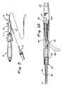
- FIGs 2-2dshow an example of a catheter system 10 of the present invention.
- This system 10comprises the combination of a vessel wall penetrating catheter 11 and a delivery catheter 12.
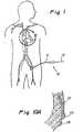
- Figure 1shows this catheter system 10 in use on a human patient.
- the vessel wall penetrating catheter 11includes an elongated catheter body 13 having a proximal end 15, a distal end 17, a handle 19 and a hub 21 coupled to the proximal end of the catheter body and to the handle.
- the handle 19may also serve as a controller for use in advancing and retracting the vessel wall penetrator 85, as described more fully below.
- the vessel wall penetrating catheter body 13includes a relatively rigid proximal section 23 shown in Figs. 2 and 3a which may be constructed, for example, of a metal hypo tube and an elongated flexible distal section or region 25 suitably joined to the proximal section. At least the distal section 25 is sized to be received within a coronary artery, and therefore can be received within either a coronary artery or a coronary vein.
- the catheter body section 13has a penetrator lumen 27 which terminates distally at an exit location or exit port 29 that is located on a peripheral wall 31 of the catheter body.
- a vessel wall penetrator 85such as a hollow NiTi needle as shown in Figures 2a (phantom lines), 2b and 2c, is disposed within the penetrator lumen 27 and is advanceable out of the side exit port 29 as seen in Figures 2a-2c.
- the exit port 29is preferably located a short distance proximally of the distal end 17.
- a radiopaque marker 33may be mounted on the lumen 27 adjacent the exit port 29 to facilitate placement and positioning of the vessel wall penetrating catheter 11.
- the penetrator 85may be a single hollow member or may consist of a series of hollow members which advance through one another or telescope in a desired manner.
- the individual membersmay ave differing curvatures or differing shapes to allow the penetrator or follow a multicurvate path of advancement. This may be useful in applications where the penetrator is required to advance around a prohibited zone or anatomical structure that the operator does not whish to penetrate.
- the catheter body 13also has a guidewire lumen 35 (Fig. 3a) which extends to the distal end 17 of the catheter body 15.
- the guidewire lumen 35extends proximally to an inlet port 37 at the peripheral wall 31 closely adjacent the proximal section 23.
- a major section 51 of the catheter body 13terminates distally in a distal opening 53, and the catheter body includes a distal tip section 55 of soft, flexible, biocompatable material (Figs. 3a and 3b).
- a proximal portion 56 of the distal tip section 55is received in the distal opening 53 and a distal portion of the distal tip section extends distally to the distal end 17.
- the distal portion of the distal tip section 55i.e. the portion of the distal tip section 55 which extends beyond the distal end of the major section 51 is of smaller cross sectional area than the adjacent region of the major section to thereby define an annular shoulder 57 on the catheter body 13.
- the exit port 29is spaced slightly proximally of the shoulder 57.
- the vessel wall penetrating catheter 11it will be desirable for the vessel wall penetrating catheter 11 to include a guidance element for guiding the positioning and rotational orientation of the catheter 11 within the vasculature such that the vessel wall penetrator 85 will be properly aimed in the direction of the target site.
- a guidance elementmay include marker(s), imaging apparatus, emitter(s), sensor(s) etc.
- the guidance elementcomprises the combination of an imaging transducer 81 and an imageable marker assembly 101.
- the imaging transducer 81is fixedly mounted on the catheter 11, and in the embodiment illustrated in Fig. 3a, the imaging transducer is mounted on the distal tip section 55 just distally of the shoulder 57.
- the imaging transducer 81is a phased array transducer and is operative to image 360° about the vessel wall catheter 11.
- the imaging transducer 81is coupled to a multiplex circuit 83 which is within the major section 51 of the catheter body 13 adjacent the shoulder 57, and the multiplex circuit 83 is in turn coupled to leads 85 which extend through the lead lumen 39, through the handpeice 19 and are attached to a connector 86 which allows the leads 39 to be connected to a viewing instrument and screen.
- the imaging transducerWhen activated, the imaging transducer emits ultrasound signals and receives back echos or reflections which are representative of the nature of the surrounding environment.
- the imaging transducerprovides an imaging signal from which an image of the surrounding structure can be created on a screen of the viewing instrument.
- the phased array transducer, the accompanying circuitry and the separate viewing instrument/screenmay be obtained from Endosonics, Inc. of Collinso Cordova, California.
- the imaging elementmay be formed of a single rotating crystal or transducer.
- the transducerwould have a single lead out, would include a drive shaft which would run back to the proximal end of the catheter through 39.
- an imageable marker 101is fixedly mounted on the catheter body 13 in a known circumferential orientation relative to the exit port 29.
- This marker 101may be in the form of a structure or cage, as shown, and the transducer 81 may be located within the marker cage or marker structure.
- the marker cagecomprises a plurality of longitudinal members 103 disposed at circumferentially spaced apart locations about a hollow interior space 105.
- the hollow space 105receives the distal tip section 55 and the transducer 81, and the transducer 81 is an onboard transducer in that it is inseparable from and not removable from the catheter body 13.
- the imageable marker 101forms on the image obtainable from the imaging signal from the imaging transducer a penetrator path indication that indicates the path that will be followed by the tissue penetrator when the tissue penetrator is advanced from the catheter.
- the path that will be followed by the penetratormay be indicated on the image by electronic means or by the use of a computer program, thereby eliminating the need for a penetrator path indicating marker 101.
- the marker 101, electronic penetrator path indicator or computer program for determination of the penetrator pathmay not only indicate the trajectory or path of the penetrator but may also indicate a stopping point at which advancement of the penetrator will stop or is intended to stop.
- the operatormay case the penetrator to be optimally positioned at the intended site without advancing the penetrator too far as may result in missing of the intended delivery site or unwanted penetration of a blood vessel or other anatomical structure that lies beyond the site at which the penetrator is desired to stop.
- the imaging transducer 81 and the marker 101are both mounted on the distal tip section 55 which has a smaller cross sectional area than does the adjacent region of the major section 51 of the catheter body 13. Accordingly, the cross sectional area of the catheter body 13 at the region containing the imaging transducer 81 and the marker 101 can still be relatively small.
- the exit location 29is closely adjacent to the imaging transducer 81 and may be, for example, about 5 mm from the imaging transducer. This minimizes the likelihood of any significant torsional displacement of the exit location 29 relative to the marker 101 and imaging transducer 89. It may also be appreciated that the imaging transducer may be mounted such that the exit port is located directly at the point at which the transducer is affixed to the catheter, illuminating any displacement.
- the vessel wall penetrating catheter 11may incorporate an emitter that is useable in conjunction with an electromagnetic, potentiometric, or other electro-anatomical mapping and/or catheter guidance/positioning systems, such as those commercially available from or under development by Biosense Webster, Inc., Diamond Bar, California; Cardiac Pathways Corporation, 995 Benicia Avenue, Sunnyvale, CA and/or Stereotaxis, Inc., 4041 Forrest Park Avenue, St. Louis, MO. Examples of these types of catheter guidance or positioning systems are described in United States Patent Nos.
- the delivery catheter 12may be advanced through the lumen of the penetrator 85 and out of its distal end.
- the delivery catheter 12may comprise a small cannula, hypotube or microcatheter formed of a suitable material such as polyimid, polytetrafluoroethylene, polypropylene, polyethylene, Pebax TM , etc.
- the delivery catheter 12may have an outer diameter of approximately 0.25-0.5 mm.
- the distal tip of the delivery catheter 12may be beveled or sharpened.
- the delivery catheter 12may have an energy emitting distal tip for enhanced tissue penetrating capability.
- a radiofrequency electrodemay be located on or near the distal tip of the delivery catheter to provide for tissue penetration enhanced by RF energy emission.
- the delivery cathetermay be adapted to ultrasonically vibrate, thereby improving its ability to penetrate through tissue.
- the body of the delivery catheter 12may be radio-opaque or one or more radio-opaque markers may be formed on the delivery catheter (e.g., at its distal tip) to permit imaging of the catheter and determination of the position of the catheter within the patient's body.
- a detachable or removable Luer connector 47may mountable proximal end of the delivery catheter 12 as shown in Figures 2 and 3b. This detachable or removable Luer connector may be removed when during proximal withdrawal and removal of the vessel penetrating catheter 11 while the delivery catheter 12 remains in place.
- the removable or detachable Luer connector 47may be attached to the exteriorized proximal end of the delivery catheter 12 and may thereafter be used for subsequent attachment of a stopcock 47 and/or syringe 50 as shown in Figure 3b.
- the proximal end of the delivery catheter 12may be devoid of any hub or connector and may be connected to a pump, delivery device, subcutaneously implanted reservoir or injection port 52, as shown in Figure 3a.
- An opening for infusion or aspiration of substances/apparatusmay be formed in the distal end of the delivery catheter 12 and/or one or more fluid outlet openings may be formed in the sidewall of the delivery catheter 12, near its distal end, as shown in figures 2c or 2d.
- one or more openingsmay be laser drilled into the delivery catheter 12, such openings being no more than 1 ⁇ 2 the diameter of the catheter lumen through which the substance is being injected, such that high pressure jets of the substance will be created as the substance exits the delivery catheter 12.
- the delivery cathetermay be straight or curved, as needed to accomplish the desired procedure.
- the delivery cathetermay constitute a very small diameter catheter of a type known in the art as a microcatheter.
- one or more interactive members 52such as sensors, emitters, etc. may be positioned on or near the distal end of the delivery catheter 12 for emitting energy as described above or for sensing, sampling or receiving information from the tissues adjacent the distal portion of the delivery catheter 12.
- Interactive members that comprise sensor(s)may provide information on the position of the delivery catheter12 or measurements of variables such as ECG, contractility, force of contraction, pressure, local ECG amplitude, local protein levels, local antibody levels, pO 2 ' pCO 2 , oxygen saturation, blood flow rate, pH, local lactate levels, etc.
- the clinicianmay assess or characterize the target site to ascertain its suitability before introducing a substance or apparatus into the target site.
- the interactive member 52may emit some facilitating energy, such as an electromagnetic field for iontophoretic transmission of the substance through the adjacent tissue.
- the interactive member 52may emit energy, such as radiofrequency energy, that will create a pocket in the surrounding tissue such that a substance or apparatus my be introduced into that pocket.
- the walls of the pocketmay be seared by the energy so as to slow the distribution of the substance out of the pocket.
- the interactive member 52may emit energy, such as ultrasound, that facilitates distribution of a substance by permeating cell membranes or by vibrating the catheter tip.
- the distal end of the delivery cathetermay be closed and a plurality of small side apertures 24 may be formed in the sidewall of the delivery catheter 12 to provide for high pressure outflow of fluid from the deivery catheter and into the surrounding tissues.
- the injection of fluids through the delivery catheter 12 into a closely confined space or interstitial sitemay result in some regurgitation or backflow of the injected fluid through the tract through which the vessel wall penetrator 85 and/or delivery catheter 12 were advanced.
- this backflow of the injected fluidmay be prevented by sealing the penetration tract or by introducing a material (e.g., an adhesive or embolizing material) into the tract during immediately after removal of the catheter 12. This may be accomplished by injecting a suitable adhesive or embolizing material such as a cyanoacrylate, polyethylene glycol, hydrogel, fibrin glue through the delivery catheter lumen as the delivery catheter 12 is being pulled back through the tissue tract through which it was initially inserted.
- a suitable adhesive or embolizing materialsuch as a cyanoacrylate, polyethylene glycol, hydrogel, fibrin glue
- the backflow of fluidmay be accomplished by a backflow barrier 22 (see Figure 4) such as an annular rib or inflatable balloon formed on the shaft of the delivery catheter 12 near its distal end so as to block backflow of fluid around the catheter shaft or alternatively by causing the fluid to solidify or become gelatinous such that it can not backflow through the penetration tract.
- a backflow barrier 22such as an annular rib or inflatable balloon formed on the shaft of the delivery catheter 12 near its distal end so as to block backflow of fluid around the catheter shaft or alternatively by causing the fluid to solidify or become gelatinous such that it can not backflow through the penetration tract.
- Such gelling or solidification of the injected fluidmay be accomplished by subsequent injection or pre-mixing of the fluid with an oil, a gelatinous polymer carrier or reactant that will cause the desired thickening or solidification of the injected fluid.
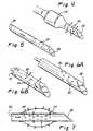
- the delivery catheter 12may incorporate anti-obstruction apparatus that will prevent cellular ingrowth or other matter from obstructing the lumen or outfow port(s) of the delivery catheter 12. Examples of such anti-blocking apparatus are shown in Figures 5-7.
- the delivery catheterhas a closed distal end 28 and a plurality of side outlet apertures 24.
- a solid stylet 26is insertable through the lumen of the delivery catheter and the outer diameter of the stylet 26 is approximately the same as the inner diameter of the delivery catheter such that, when inserted, the stylet 26 will substantially close-off or block the side apertures 24 thereby preventing cellular ingrowth or other matter from entering the side apertures 24 or lumen of the delivery catheter.
- the stylet 26may be inserted into the delivery catheter at times when no fluids or other substances are being infused, but may be removed at appropriate times to allow the desired infusions of fluids or other substances through the delivery catheter.
- the stylet 26could have a lumen which extends longitudinally through the stylet to a closed distal end and side aperture(s) or slot(s) or other opening(s) could be formed in the stylet so as to be alignable with the side apertures 24 of the delivery catheter.
- the styletwould be maintained in one position when it is desired to block the side apertures 24 to prevent cellular ingrowth or other matter from entering the side aperture's or lumen of the delivery catheter but may be rotated or otherwise moved to a second position wherein the aperture(s), slot(s) or other opening(s) of the style at 26 would become aligned with the side aperture's 24 of the delivery catheter is such that fluid may be injected through the lumen of the style that and outwardly through the side apertures of the delivery catheter 24. Thereafter, when the fluid injection has been completed, the stylet could be once again rotated or otherwise moved to the first position to once again close-off or block the side apertures 24 of the delivery catheter.
- Figures 6a and 6bshow another embodiment wherein the delivery catheter has a closed distal end 28 and a plurality of side outlet apertures 24.
- an inflatable obturator 30is disposed within the lumen of the delivery catheter. When the obturator 30 is inflated, as shown in Figure 6a, it will close-off or block the side apertures 24 thereby preventing cellular ingrowth or other matter from entering the side apertures 24 or lumen of the delivery catheter. However, when the obturator 30 is deflated, as shown in Figure 6b, fluids may be infused in the distal direction through the lumen of the delivery catheter and out of the side apertures 24.
- a semi-permeable diffusion barrier 58is mounted about the outer surface of the delivery catheter so as to cover the catheter's side apertures 24.
- This diffusion barrier 58is in the nature of a balloon and is formed of material that permits the substances or fluids injected through the catheter to diffuse outwardly through the barrier 58, but also prevents cellular ingrowth or other matter from invading the interior of the barrier 58 and entering the side apertures 24 or lumen of the delivery catheter.
- the desired semi-permeability of the diffusion barrier 58may be a function of the size of pores or openings in the barrier or balloon 24.
- polymer films having appropriately sized poresmay be used to form the diffusion barrier 58.
- One polymer material that may be used in film form to create the diffusion barrier 58is commercially available as Nutrapore TM from Anamed, Inc., 1 Technology Drive, Bldg. D-409, Irvine, CA 92618 .
- Figures 8a and 8bshow another embodiment of a delivery catheter 12 having it opened distal end and a spring-mounted tip member 42 disposed within the distal end of the catheter 12.
- the tip member 42has a fluid flow channel 44 that extends through the tip member 42 and opens through the side of the tip member 42, as shown.
- the tip member 42is attached to the catheter 12 by way of a spring 40.
- the spring 40is biased to a contracted position as shown in Figure 8a, wherein the tip member 42 is drawn into the lumen of the catheter 12 such that the side opening of the fluid flow channel 44 is covered by the wall of the catheter 12 and cellular ingrowth or other matter is thereby prevented from entering the fluid flow channel 44 or lumen 32 of the delivery catheter 12.
- a delivery catheter 12that has an open distal end, a generally conical tip member 408 and a coil spring member 46 which attaches the tip member 48 to the distal end of the catheter 12.
- the coil spring member 46is biased to a retracted position, as shown in Figure 9a, wherein the convolutions of the coil spring member 46 are drawn into abutment with one another and with the respective ends of the catheter body 12 and tip member 48. In this manner the distal end of the catheter 12 is substantially closed, and cellular ingrowth or other matter is prevented from invading the lumen of the catheter 12.
- fluidmay be continually or periodically infused into a tissue pocket or reservoir at the distal end of the delivery catheter 12 and subsequently re-aspirated through the delivery catheter lumen.
- the delivery catheter 12may have multiple lumens, one for infusion of fluid and one for withdrawl of fluid, and a periodic or continual infusion and withdrawal of fluid may be performed to keep these lumens of the delivery catheter 12 open and unobstructed with cellualr ingrowth, clots, debris or other matter.
- the delivery catheter 12may incorporate mechanical hooks, screws, barbs or other anchoring members (not shown) that engage surrounding tissue and deter inadvertent migration or movement of the delivery catheter 12 after it has been implanted.
- anchoring membersmay be formed of bioabsorbable material and may be designed to break away, detach upon delivery of a pulse of energy or to be otherwise jettisoned when the delivery catheter 12 is purposefully removed from the body.
- the optional interactive member 52comprises an energy emitter or electrode, such as a radiofrequency electrode, such interactive member 52 may be actuated after the delivery catheter 12 is in place for the purpose of fusing the catheter 12 to the surrounding tissue.
- chemical glues, adhesives, or an ingrowth matrixsuch as a fabric (e.g., a woven material such as Dacron) into which surrounding tissue will grow, may be disposed on the delivery catheter 12 or introduced through the delivery catheter 12 after it is positioned, to deter inadvertent movement of the delivery catheter 12.
- a fabrice.g., a woven material such as Dacron
- the outer surface of at least the portion of the delivery catheter that becomes inserted into the patient's bodymay be coated or impregnated with and antibiotic or antimicrobial substance (e.g. provodine iodine, silver compounds, etc.) or other drugs or substances that affect the surrounding tissue in a desired way (e.g., a heparin coating that will reduce clot formation in areas adjacent to the catheter or within the blood vessels through which the catheter extends).
- antibiotic or antimicrobial substancee.g. provodine iodine, silver compounds, etc.
- other drugs or substances that affect the surrounding tissue in a desired waye.g., a heparin coating that will reduce clot formation in areas adjacent to the catheter or within the blood vessels through which the catheter extends.
- an anti-microbial coatingthat may be applied to the delivery catheter 12 is a proprietary material containg silver, carbon and platinum and used commercially under the name Oligon TM (Edwards Lifesciences Corporation, Irvine, California).
- Oligon TMEdwards Lifesciences Corporation, Irvine, California.
- examples of commercially available heparin coatings that may be usedinclude heparin-benzalkonium chloride complex, heparin-TDMAC complex and other medical coatings available from STS Biopolymers, Inc.336 Summit Point Dr., Henrietta, NY.
- the delivery catheter 12may optionally incorporate, or may be used in conjunction with, apparatus for creating a pocket (e.g., a void) within tissue located adjacent to the outflow aperture(s) 24 of the delivery catheter 12 such that substances infused through or apparatus introduced through the delivery catheter 12 will be received within that pocket.
- a pockete.g., a void
- an expandable cagemay be deployable through or from the delivery catheter 12 to spread or separate the adjacent tissue, thereby creating the desired pocket.
- the above-described interactive member 52may comprise an energy emitting apparatus capable of creating a pocket adjacent thereto.
- the interactive member 52may comprise a radiofrequency electrode that, when actuated, will ablate the adjacent tissue thereby creating the desired pocket.
- the pocket creating apparatusmay comprise a laser port through which ablative laser energy may pass into the adjacent tissue, or a nozzle through which a high pressure jet of fluid may be injected so as to sever or separate the adjacent tissue, thereby creating the pocket.
- Figure 13shows that the vessel wall penetrator 85 may be of a pre-bent, curved configuration such that incremental advancement of the penetrator may cause its distal tip to be incrementally positioned at a series of different locates, such as point A (PA), point B (PB), point C (PC) and point D (PD) shown in Figure 13.
- the delivery catheter 12may then be advanced out of the penetrator at each of the points and drug or substances may be injected at periodic depot locations DL along the path of each advancement or retraction of the delivery catheter 12. In this manner, the drug or other substance may be deposited relatively uniformly over a generally wedge shaped region of tissue with only one penetration through the vessel wall.
- Figure 1generally depicts a catheter system 10 of the above-described type being used to perform a procedure fortransvenous placement of a delivery catheter 12 in an ischemic region of the patient's myocardium (i.e., the target site) so that a substance or apparatus may be acutely or chronically delivered directly into the target site.
- This procedurebegins with the percutaneous insertion of the vessel wall penetrating catheter 11 into the patient's femoral vein and advancement of the vessel wall penetrating catheter 11 trough the inferior vena cava, through the right atrium, through the coronary venous sinus and into a coronary vein as shown in detail in Figure 11.
- a vessel wall penetrator 85is then advanced from the vessel wall penetrating catheter 11 and through the wall of the coronary vein in which the vessel wall penetrating catheter 11 is positioned.
- a delivery catheter 12is advanced through the vessel wall penetrator 85 to the target location within the patient's myocardium.
- the vessel wall penetrating catheter 11will be provided with or associated with guidance elements as described hereabove to guide the positioning, rotational orientation of the catheter 11 within the patient's body and/or the path, trajectory and extent of advancement of the penetrator 85.
- these guidance elementswill be used to guide the longitudinal position and rotational orientation of the vessel wall penetrating catheter 11 before the penetrator 85 is advanced from the catheter 11. Thereafter, after the delivery catheter 12 has been advanced through the penetrator 85 to the target site, the penetrator 85 may be retracted into the vessel wall penetrating catheter 11 and the vessel wall penetrating catheter 11 may be withdrawn and removed, leaving only the delivery catheter 12 in place.
- an interactive member 52such as an emitter, sensor, marker, electrode, etc. may be mounted on the delivery catheter 12.
- This interactive member 52may be sensor (e.g., an electrode, optical sensor, chemical sensor, strain gage, flow meter, etc) that is connected to a receiver or instrumentation located outside the patient's body so as to provide information or analytical data regarding from the target site TS.
- Examples of the types of information or data that may be sensed and provided from the target siteinclude ECG, contractility, force of contraction, pressure, local ECG amplitude, local protein levels, local antibody levels, pO 2 , pCO 2 , oxygen saturation, blood flow rate, pH, local lactate levels, etc.
- Substances or apparatusmay be introduced through the lumen of the delivery catheter 12 at desired time points or intervals. Also, separate sensor(s) or other separate apparatus may be delivered through the delivery catheter 12 so as to provide diagnostic information or other information regarding the physiological status of the myocardium in which the delivery catheter 12 is indwelling and/or the specific positioning of the distal end of the second catheter 12. After all of the desired sampling, diagnosis, delivery of substances and/or delivery of apparatus has been completed, the dosing catheter 12 may then be removed from the body of the patient.
- tissue penetrating catheters 10 useable in this inventioninclude those described in PCT International Patent Publications No. PCT/US99/07115 and PCT/US99/07112 .
- the delivery catheter 12may comprise any suitable type of flexible catheter sized to pass through the lumen of the vessel wall penetrator 85 in the manner described here above.
- Examples of commercially available extrusion that may be used to form the delivery catheter 12include a
- the types of substances that may be deliveredinclude angiogenic factors (e.g. VEGF, FGF, EGF, PDGF or Hepatocyte Growth Factor ("HGF")), gene therapy compositions (e.g. a replication-deficient adenovirus vector containing a transgene which codes for an angiogenic protein or peptide), pro-angiogenic agents or combinations (e.g.
- angiogenic factorse.g. VEGF, FGF, EGF, PDGF or Hepatocyte Growth Factor (“HGF")
- gene therapy compositionse.g. a replication-deficient adenovirus vector containing a transgene which codes for an angiogenic protein or peptide
- pro-angiogenic agents or combinationse.g.
- an adenosine receptor agonist in combination with heparinmyocardial cells, myocytes, myoblasts, or other cardiac or systemic drugs such as antiarithmic agents, beta blockers, calcium channel antagonists, platelet glycoprotein (GP) IIb/IIIa inhibitors, etc.
- the inventionmay be used to treat neurdegenerative diseases such as Parkinson's Disease, Amilotrophic Lateral Sclerosis (Lou Gehrig's Disease), Alzheimer's Disease, etc.)
- neurdegenerative diseasessuch as Parkinson's Disease, Amilotrophic Lateral Sclerosis (Lou Gehrig's Disease), Alzheimer's Disease, etc.
- GDNFglial cell line-derived neurotropic factor
- nerve growth factornerve growth factor
- neuro-immunophilin ligandpoly ADP-Ribose polymerase
- the delivery catheter 12will be provided with small side apertures 24 and a closed distal end, or some other aperture or nozzle arrangement, that causes the substance to be expelled from the delivery catheter 12 in fine, high velocity jets or streams such that dissemination of the substance into the surrounding tissue will be enhanced.
- an interactive member 52 on the delivery cathetermay be used emit energy or otherwise interact with the delivered substance to affect the substance in a desired way (e.g., to emit an iontophoretic field to drive the substance into adjacent tissue or to cause the distal tip of the delivery catheter 11 to become warm or to vibrate ultrasonically in a way that enhances the distribution or cell membrane permeation of the substance).
- a substance injected through the delivery catheter 12may be mixed with or followed by a second substance which causes the first substance to solidify, gel, adhere or to become otherwise altered in a desired manner (e.g., in a way that affects the distribution, bioavailability, potency, duration of action or pharmacologic activity of the first substance.
- a mixture of angiogenic factorse.g., VegF and FGF
- a liquid polymer matrixmay be prepared in a liquid polymer matrix and injected in a bolus through the delivery catheter 12 into a myocardial target site.
- a second solution containing a catalyst that causes the polymer matrix to solidify to form a biodegradable solidmay be injected as a second bolus through the delivery catheter.
- the mixture of the fist solution with the second solution within the target sitewill cause the fist solution to solidify in the form of a biodegradable solid or foam.
- This in situ solidification of the matrixwill cause the injected angiogenic factors to remain within the target site for a longer period of time than if they had been injected and allowed to remain as an aqueous solution. Examples of materials that may be formed in situ in this application include those described in United States Patent No. 6,139,574 (Vacanti ).
- the present inventionallows for mapping or assessment of the site at which the delivery catheter 12 is positioned to confirm that the site is, or continues to be, suitable for the intended purpose.
- a radio-labeled compound, radioisotope or other traceable substancemay be introduced through the delivery catheter and the rate at which the radio-labeled substance or isotope distributes away from the injection site may be measured by well known techniques. If the distribution away from the site is determined to be too rapid or too slow, the delivery catheter 12 may be repositioned before the desired therapeutic or diagnostic substance is injected.
- this techniquemay be used to ensure that the delivery catheter 12 has not migrated or moved from the intended injection site, or that the site has not become excessively vascularized since delivery of the last dose.
- the above-described examples of the application of the catheter system 10may further be combined with some or all of the other optional elements of the catheter system 10 described here above, such as the high-pressure distribution nozzles, tissue-pocket-creating apparatus, sponges or other apparatus/substances afford to wait or affect the dissemination or distribution of the injected substance, anti-obstruction apparatus, apparatus/substances for a three of the delivery catheter, sensors or other apparatus for characterization of the targets i.e. or regions adjacent the delivery catheter, etc.
- the present inventionfurther includes a method wherein a retrovenous delivery catheter 112, a shown in Figures 11 and 12, is used to deliver a substance into a vein while temporarily obstructing the vein, thereby allowing the substance to enter a target ste by undergoing retrograde flow through the venous vasculature to a capillary bed at the target site.
- the retrovenous delivery catheter 112generally comprises a flexible tubular catheter described hereaboveof the above-described type may be inserted into a selected vein (e.g., a coronary vein) and used acutely or chronically to deliver substances to a particular target site by retroperfusion of the substance through the vein, to a capillary bed located within the target site.
- the retrovenous catheter 112has a distal end opening and an inflatable occlusion balloon 50 formed a spaced distance proximal to the distal end opening.
- the catheter 112is inserted into the venous vasculature and advanced into a specific vein such as a coronary vein located near an area of ischemic myocardium, as shown in Figures 11 and 12.
- the occlusion balloon 50is inflated so as to occlude the vein and prevent venous blood from flowing through the vein in the normal direction of venous blood flow.
- the desired substance(e.g., a drug or biological) is then injected through the catheter 112 and out of its distal end opening into the vein. Because the vein is occluded by the balloon, the injected substance will flow in retrograde fashion through the vein and to the capillary bed within the ischemic region of the myocardium.
- the balloonmay remain inflated for a desired period of time to allow the drug or substance to be effectively absorbed by the tissues adjacent to that capillary bed. Thereafter, the balloon is deflated, allowing normal venous flow through the vein.
- the catheter 112may be removed after a single dose is delivered or it may remain indwelling for a period of time (e.g., hours, days, weeks or months) to permit repeated doses to be delivered by repeating the foregoing injection procedure. Any or all of the attributes and options described above with respect to the extravascular delivery catheter 12 may also be incorporated into this retrovenous delivery catheter 112, to the extent feasible and not adverse to the intended function of this retrovenous delivery catheter as described herein.
- FIGS 14-19show embodiments of the invention that may be used for delivery of substances or articles into the myocardial wall via an endocardial approach.
- the tissue penetrating catheter 10, 200 or 200ais advanced through the vasculature to a position within a chamber of the heart.
- the penetrator 85, 204 or 206is advanced from the catheter body 13, 202 or 202a and into the adjacent wall of the heart.
- a delivery catheter 12is then advanced through the lumen of the penetrator 85, 204 or 206 and into the myocardium.
- a desired substancemay then be injected through the delivery catheter 12 and onto the myocardium at desired location(s).
- the configuration of the penetrator 85, 204, 206may control the direction in which the delivery catheter 12 advances.
- the penetrator 85, 204 or 206may be configured such that it directs the delivery catheter 12 in a direction that is substantially or roughly parallel to the adjacent endocardial wall of the myocardium.
- a catheter system 200comprising an elongate flexible catheter body 202 having a distal end opening 203 out of which a resilient tissue penetrator 204 is advanceable.
- the tissue penetrator 204in the particular embodiment shown comprises a hollow needle.
- the penetrator 204that is pre-bent such that a single, gradual 90° bend is formed therein, as shown.
- the catheter body 202is advanced through the vasculature and into a chamber of the heart (e.g., the left ventricle).
- the distal end DE of the catheter body 202is placed in abutting_contact with, or close to, the endocardial surface of the myocardium. Thereafter, the penetrator 204 is advanced out of the distal end opening 203 and into the myocardium M.
- the approximate 90°bend formed in the penetrator 204causes the distal tip of the fully advanced penetrator 204 to be aimed in a direction that us generally perpendicular to the longitudinal axis of the catheter body 202 and generally parallel to the endocardial surface of the myocardium.
- the delivery catheter 12is then advanced through the lumen or bore of the hollow penetrator 204, out of the distal end of the penetrator 204 and though a quantity of myocardial tissue in a direction that is generally parallel to the endocardial surface of the myocardium.
- the desired drug or substanceis then injected through the delivery catheter 12.
- it is possible to create a continuous trail of substance or a plurality of spaced-apart substance deposition sitesby slowly withdrawing or advancing the delivery catheter 12 while continuously or periodically injecting the desired substance through the delivery catheter. If subsequent dosing or later delivery of substance or apparatus is desired, the penetrator 204 may be retracted into the catheter body 202 and the penetrating catheter 200 may be removed, leaving the delivery catheter 12 in place for subsequent use.
- the tissue penetrator 206comprises a resilient hollow needle that is preformed to a helical or corkscrew configuration.
- the catheter body 202ais advanced into a chamber of the heart and maneuvered to a position where its distal end is in abutment with or close-spaced to the endocardial surface of the myocardium.
- the penetrator 206is advanced out of the catheter's distal opening 203a and the penetrator 206 is rotated as it is advanced into the myocardium.
- the rotation of the penetrator 206 as it is advancedcauses the corkscrew penetrator 206 to essentially screw into the myocardium.
- the delivery catheter 12is then advanced through the lumen of the penetrator and into the myocardium where it is used, in the manner described above, to deliver the desired substance in a desired deposition area 207 (e.g., a trail, elongate track, series of depots or deposits, in a line, etc.)
- a desired deposition area 207e.g., a trail, elongate track, series of depots or deposits, in a line, etc.
- the delivery catheter 12may be retracted into the lumen of the penetrator 206 and the penetrator 206 may be rotated to a new position, at which time the delivery catheter may once again be advanced into an area of myocardial tissue that is different from the area into which the delivery catheter had been previously advanced.
- an array of substance deposition patterns 207may be formed in a substantial 360° radius around the central axis of the corkscrew penetrator 206 as illustrated in Figure 16a. If subsequent dosing or later delivery of substance or apparatus is desired, the penetrator 206 may be rotatably retracted into the catheter body 202a and the penetrating catheter 200a may be removed, leaving the delivery catheter 12 in place for subsequent use.
- FIG 17shows an example of the use of a side exiting penetrating catheter system 10a that is a modification of that type shown in Figures 2 and 2a.
- This catheter systemis also useable to accomplish the delivery of a substance into the myocardial wall, via an endocardial approach.
- the tissue penetrating catheter 10acomprises a catheter body 13a which may be the same or similar to that shown in Figures 2 and 2a or may be constructed in any suitable manner known in the art of catheter design and construction.
- a penetrator exit port 37ais formed in the catheter body 13a and a curved penetrator 85a comprising a hollow needle is advanceable from the exit port 37a as shown in the example of Figure 17.
- An optional guide cathetermay be used to guide the penetrating catheter to a position adjacent the wall of the atrium or ventricle in the area where it is desired to deliver the substance (or article).
- the penetrating catheter body 13is maneuvered into juxtaposition with the endocardial surface of the myocardium, with or without the use of the optional guide catheter 210.
- the penetrating catheter 10ais then placed in a rotational orientation whereby the side exit port 37a is aimed at or directly juxtaposed with the endocardial surface to be penetrated.
- Optional rotational-orientation-indicating markers on the catheter body 13a, imaging apparatus (on board the catheter body 13 a or located elsewhere), electro-anatomical catheter navigation systems or other apparatus for discerning the specific rotational orientation of the catheter relative to the trajectory or path upon which the penetrator 85a will advance,may be used as described above and in the prior patent applications incorporated herein by reference.
- the penertator 85ais advanced into the adjacent myocardial tissue.
- the curve(s) and shape of the penetator 85aare such that as it advances it reaches a position where its distal tip is directed generally parallel to the endocardial surface, as shown in Figure 17.
- the delivery catheter 12is advanced through the penetrator 85a and into the myocardium.
- the positioning and shape of the penetratorcauses the delivery catheter to advance on a path that does not result in the delivery catheter a) repuncturing through the endocardium and into the chamber of the heart or b) passing outwardly through the epicardial surface of the heart and/or c) perforating a substantially sized coronary blood vessel in a manner that would cause untoward bleeding or other potential complications.
- the substance (or article)is then in injected through the delivery catheter and into the myocardium.
- the penetrator 85amay be retracted into the catheter body 13a and the penetrating catheter 10 may be removed, leaving the delivery catheter 12 in place for subsequent use.
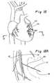
- Figures 18 and 19show an example of a procedure wherein a therapeutic substance (e.g., myoblasts, angiogenic factors, muscle grafts, etc.) may be deposited directly into an infarct zone IZ wherein myocardial tissue has become necrotic.
- a therapeutic substancee.g., myoblasts, angiogenic factors, muscle grafts, etc.
- the penetrating catheter 10has been advanced into a coronary vein CV adjacent to the infarct zone IZ.
- a penetrator 85 having an approximate 90 degree curvatureis advanced from the penetrating catheter 10, though the wall of the coronary vein CV and into or near the infarct zone IZ.
- the delivery catheter 12is then advanced though the lumen of the penetrator 85 and though all or a portion of the infarct zone, as specifically shown in Figure 19.
- Figure 19illustrates a previously created deposition patter DP (see cross-hatched area on Figure 19). This previously created deposition pattern DP is an elongate region, as shown.
- a deposition apttern axis DPA projected through the elongate deposition pattern DPis non-perpendicular and preferable tangential or nealy tangential to the adjacent endocardial surfaces of the right and left ventricles RV, LV.
- this generally tangential or non-perpendicular approachallows a greater length of delivery catheter 12 to be advanced into the myocardium than would have been possible if the penetrator 85 had been aimed or directed such that the delivery catheter 12 advanced perpendicular to and toward the left or right ventricle LV, RV.
- the procedure illustrated in Figures 18-19may be used to revitalize or restore function to regoins of the myocardium that are necrotic or severely damaged.
- this techniquemay be useable to treat congestive heart failure.
- this techniquemay also be used to implant grafts of muscle tissue into the myocardium.
- a coring needlemay be used to harvest an elongate segment of healthy cardiac or other muscle tissue.
- That harvested tissue graftmay then be loaded into the delivery catheter 12 and deposited into the infarct zone IZ as the delivery catheter 12 is retracted, thereby creating an elongate tissue graft that extends fully or partially through the infarct zone IZ.
Landscapes
- Health & Medical Sciences (AREA)
- Life Sciences & Earth Sciences (AREA)
- Surgery (AREA)
- Animal Behavior & Ethology (AREA)
- Public Health (AREA)
- Veterinary Medicine (AREA)
- General Health & Medical Sciences (AREA)
- Engineering & Computer Science (AREA)
- Biomedical Technology (AREA)
- Heart & Thoracic Surgery (AREA)
- Vascular Medicine (AREA)
- Molecular Biology (AREA)
- Medical Informatics (AREA)
- Reproductive Health (AREA)
- Nuclear Medicine, Radiotherapy & Molecular Imaging (AREA)
- Anesthesiology (AREA)
- Biophysics (AREA)
- Pulmonology (AREA)
- Hematology (AREA)
- Cardiology (AREA)
- Media Introduction/Drainage Providing Device (AREA)
- Infusion, Injection, And Reservoir Apparatuses (AREA)
- Acyclic And Carbocyclic Compounds In Medicinal Compositions (AREA)
- Surgical Instruments (AREA)
- Medicines That Contain Protein Lipid Enzymes And Other Medicines (AREA)
- Apparatus For Radiation Diagnosis (AREA)
Abstract
Description
- There exist many situations in which it is desirable to deliver substances (e.g., drugs, biological materials, etc) or apparatus (e.g., wires, sensors, etc.) to specific locations within tissues (i.e. an "interstitial target site") of the body of a human or veterinary patient. Examples of the types of tissues wherein such target sites may be located include myocardial tissue, brain tissue or tumors.
- Some catheters and drug delivery stents of the prior art have been purportedly useable toindirectly deliver drugs or substances to specific interstitial target locations by first dispensing the drugwithin the lumen of a nearby blood vessel or on the inner surface of a nearby blood vessel and then allowing the drug to migrate through the blood vessel wall or through a downstream capillary bed, to the desired interstitial target location.
- The prior art has also included catheter devices that may be used for delivering substances or apparatus directlyinto interstitial target locations by guided advancement of a penetrating cannula or needle from a catheter located within the lumen of a nearby blood vessel, through the wall of the blood vessel and through any intervening tissue, to the interstitial target site. The desired substance or apparatus may then be infused or delivered directly into the target interstitial site without any need for transmural diffusion through the blood vessel wall or downstream transluminal flow to the selected capillary bed. Examples of these catheter devices useable for direct delivery of drugs or apparatus into interstitial target sites are described in PCT International Patent Publications No.
PCT/US99/07115 PCT/US99/07112 - Particular interest has developed in methods for controlled or targeted delivery of substances such as drugs (e.g., chemotherapeutic agents), gene therapy compositions (e.g., plasmids, viral vectors, genetically modified cells, naked DNA), biological factors (e.g., angiogenic factors, nerve growth factors, other cell growth factors, other proteins), monoclonal antibodies, or specific cell types (e.g., stem cells or other progenator cells, pancreatic islet cells, dopamine secreting neurons, endothelial cells, myocardial cells, other myocytes, etc) into interstitial target locations for the purpose of treating diseases such as myocardial ischemia, solid tumor types of cancer, parkansonism, diabetes, etc. Specifically, in the treatment of myocardial ischemia, research has indicated that introduction of certain angiogenic substances into ischemic areas of myocardium may result in "therapeutic angiogenesis" in patients who suffer from clinically significant coronary artery disease. Generally speaking, the term "angiogenesis" refers to the creation of new capillaries and/or blood vessels within the parenchyma of an organ, within a tumor or within an area of tissue (e.g., myocardium). Angiogenesis is believed to occur as a multistep process in which endothelial cells focally degrade and invade through their own basement membrane, migrate through interstitial stroma toward an angiogenic stimulus, proliferate proximal to the migrating tip, organize into blood vessels, and reattach to newly synthesized basement membrane. The term "therapeutic angiogenesis" involves the administration of angiogenic substances or treatments to promote one or more steps in the angiogenesis process thereby providing for the creation of new blood flow in tissue that previously lacked sufficient blood flow.
- Various approaches have heretofore been used for delivery of angiogenic substances into the myocardium. One approach is the use a tissue penetrating device such as a laser to create penetration tracts or transmyocardial (TMR) channels which extend from either the epicardial (outer) surface or endocardial (inner) surface of the heart into the myocardium, and to then inject quantities of angiogenic substances into those TMR channels. Examples of this approach are described in
United States Patent Nos. 5,925,012 (Murphy-Chutorian, et al. ),25 5,999,678 (Murphy-Chutorian, et al. ) And6,106,520 (Laufer, et al. ) WO-A-99/48545 United States Patent No. 5,366,490 (Edwards et al. ) describes medical probe which comprises a catheter having a stylet guide housing with one or more stylet ports in a side wall thereof and guide means for directing a flexible stylet outward through the stylet port(s) and through intervening tissue at a preselected, adjustable angle to a target tissue.- There remains a need in the art for the development of new apparatus and methods for delivering substances or apparatus to specific target sites within tissues, tumors or organs of the body with minimal trauma to the tissues and optimum control as to the precise location(s) at which the substances or apparatus are introduced.
- According to an aspect of the present invention there is provided a system for delivering substances or apparatus to a target site located within the body of a human or veterinary patient as claimed in
Claim 7. - Also described herein are transluminal methods, devices and systems for delivering substances (e.g., drugs or other therapeutic or diagnostic agents) or articles (e.g., devices, apparatus, wires, sensors, thermistors, etc.) to interstitial sites within the body of a human or veterinary patient.
- In accordance with one aspect of the invention, there is provided a system comprising a) a penetrating catheter that is positionable within the vasculature (e.g., a blood vessel, vascular sinus or chamber of the heart) of a human or animal patient and which has a penetrator advanceable from the catheter in the direction of an extravascular target site and b) a delivery catheter that is advanceable from the penetrator to the target site. As used herein, the term "vessel wall" shall mean not only the wall of a blood vessel (i.e., artery or vein) but also the endocardium surrounding a chamber of the heart or any other wall of an anatomical structure in which the penetrating catheter is positioned and through which the penetrator advances to reach its intended position within adjacent tissue. The Substance(s), article(s) or apparatus may then be delivered to the target site through the delivery catheter and/or samples of body fluid or other information may be obtained from the target site through the delivery catheter. In applications where it is desired to use the delivery catheter continuously or intermittently over an extended period of time (e.g., hours, days, weeks or months) the penetrator may be withdrawn into the vessel wall penetrating catheter and the vessel wall penetrating catheter may be removed, leaving just the delivery catheter in place (e.g., extending through the patients blood vessel(s), outwardly through the penetration formed in the blood vessel wall and to the target site.) Also, the substance or artice(s) may be injected periodically or continuously as the delivery catheter is being advanced or retracted, so as to provide a continuous "trail" or series of deposition sites wherein the substance or article(s) is/are deposited.
- In accordance with the invention, the use of a unicurvate or multicurvate penetrator (or a curved delivery catheter in combination with a straigt, unicurvate or multicurvate penetrator) may serve to guide the delivery catheter on a path that is navigates around anatomical structures or avoid penetration into a cavity, organ or anatomical structure that the operator does not wish for the delivery catheter to enter. In this regard, the delivery catheter may be guided such that it advances on a path that is generally tangential to the wall or edge or a chamber of the heart or other cavity or anatomical structure that the operator does not wish to enter or penetrate. This ability to avoid penetration of a chamber, cavity or anatomical structure may allow a greater length of the delivery catheter to be advanced into the tissue than would have been otherwise possible. The advancement of a greater length of delivery catheter into the tissue may allow for deposition of a longer trail or a more lengthy series of depots of an injected material than would be possible if the delivery catheter were to have been advanced in the direction of or non-tangentially to the chamber of the heart or other cavity or anatomical structure that the operator does not wish to enter or penetrate. Also, the ability to provide a lengthy trail or series of deposition sites may be advantageous in certain applications of the invention. For example, the ability to deposit a tissue graft or cells (e.g., stem cells, myoblasts, etc.) in an elongate trail may allow for the cells to form an organized structure wherein the cells communicate with one another and/or form a connection between two spaced apart regions of an organ or tissue mass. In cases where angiogenic substances are being injected through the delivery catheter, the ability to lay down a trail of the angiogenic substance may permit the operator to define a line or elongate region of new blood vessel growth. Also, advancement of a more lengthy segment of the delivery catheter into the tissue may provide for deeper injection of substances with less potential for bleedback or regurgitation through the interstitial tract created by advancement of the penetrator and/or delivery catheter. Also, this capability of the system allows for the deposition of a series or network of elongate trails or tracts of a substance or article, or spaced apart interstitial deposits of a substance or article in a manner that allows the individual trails, tracts or deposits to form a network and to interact with one another in a desired manner.
- The types of substances that may be delivered through the delivery catheter include drugs (thrombolytics, platelet inhibitors, anti-restenotic agents, beta blockers, ion channel antagonists, positive or negative ionotropic agents, anti-arrhythmics, antibiotics, analgesics, chemotherapeutic agents, other anti-neoplastic agents, etc.), natural or recombinant proteins (e.g., angiogenic proteins such as vascular endothelial growth factor (VEGF), fibroblast growth factors (FGF), epidermal growth factor (EGF), platelet-derived growth factor (PDGF) nerve cell growth factor (NGF) or hepatocyte growth factor (HGF)), cells or cellular preparations (e.g., stem cells, other progenetor cells, myocytes, myoblasts, pancreatic islet cells, dopamine secreting cells, etc), genes or gene therapy preparations (e.g., viral vectors containing genes for gene therapy applications, genetic material for electrophoretic transmission into cells, plasmids, viral vectors, genetically modified cells, naked DNA, etc.), contrast media or dyes for imaging, radio-labeled diagnostic materials or drugs or other traceable substances, mixtures of any of the above, alone, in solution or in combination with any delivery substance or matrix (e.g., polymer matrices used to inhibit or slow distribution or dissemination of a substance away from its original injection site), dialysis solutions or micro-dialysis solutions, or any other type of substances that may be introduced through the delivery catheter for any therapeutic, imaging, diagnostic or other purpose.
- Further in accordance with the invention, the types of target tissues into which the delivery catheter of the above-described system may be placed include various organs (e.g., heart, brain, liver, pancreas), the walls of blood vessels (by injection directly into the vessel wall or by injection into a periadventital area outside of but close to the vessel so that the drug or substance will be distributed into the vessel wall), muscles (e.g., myocardium, skeletal muscle) or aberrant masses (e.g., tumors, cysts).
- Still further in accordance with the invention, substances delivered through the delivery catheter may be of increased viscosity to deter their egress from the target area, may be adherent to tissues in the target area so as to deter egress of the substance from the target area and/or may harden or form a mass in situ after injection into the target area, thereby deterring egress of the substance from the target area.
- Still further in accordance with the invention, the outlet port(s) of the delivery catheter may be configured such that substances injected through the delivery catheter will form high pressure jet sprays into the tissue surrounding the delivery catheter.
- Still further in accordance with the invention, the vessel wall penetrator of the vessel wall penetrating catheter and/or the delivery catheter may be equipped with backflow deterrent for limiting or preventing fluid that is injected through the delivery catheter from bleeding back through the tissue tract through which the delivery catheter and/or penetrator was/were advanced. In chronic dosing applications wherein the delivery catheter remains indwelling, such backflow deterrent may comprise a balloon, annular rib or other barrier formed on the outer surface of the delivery catheter to block the backflow of fluid through the tract in which the delivery catheter resides. In acute dosing applications wherein the delivery catheter is extracted and removed immediately after injection of the substance, the backflow deterrent may comprise a) an embolizing member such as a detachable blocker, balloon, clot, fibrin, bead of polyvinyl alcohol, etc. that is deployed into the tissue tract as the delivery catheter and/or penetrator is/are retracted, b) a substance such as a cyanoacrylate, polyethylene glycol, hydrogel, fibrin glue or other material is injected to embolize, seal or close the tract through which the delivery catheter and/or penetrator was/were advanced or c) a tissue fusing device, such as a radiofrequency emitting electrode, for welding or fusing adjacent tissue in a way that effectively closes the tract through which the delivery catheter and/or penetrator was/were advanced.
- Still further in accordance with the invention, the delivery catheter of the above-described system may be used for aspiration of samples of blood or body fluid from the target site and/or may include one or more interactive members, such as emitters, detectors, electrodes, sensors, etc. for a) facilitating the delivery catheter's penetration through tissue, b) facilitating the distribution of an injected substance into surrounding tissues (e.g., by iontophoresis), c) creating a pocket into which a substance may be injected or d) sensing the position of the delivery catheter or some content or variable (e.g.,ECG, contractility, force of contraction, pressure, local ECG amplitude, local protein levels, local antibody levels, pO2, pCO2, oxygen saturation, blood flow rate, pH, local lactate levels, etc.) of the adjacent tissue.
- Still further in accordance with the invention, the delivery catheter may be used to continuously or intermittently monitor physiological parameters or variables (e.g., rate of blood flow away from the site) or pharmacokinetic or biodistributive parameters or variables (e.g., the rate at which a substance will distribute away from the target site, how long the injected substance may be expected to remain at the target site, the rate at which the injected substance may be inactivated or metabolized at the target site and/or other parameters/variables relating to the activity of the substance after it has been injected at the site). Such information may then be used to verify that the delivery catheter is suitably placed for optimal or desired therapeutic effect of an injected substance or apparatus delivered to the site. If it is determined that an injected substance is likely to distribute away from the target site too quickly, or remain at the target site for too long, or become inactivated too quickly or not quickly enough, the delivery catheter may be reposition to a site that is more desirable. Similarly, if it is determined that the site is too vascularized or not vascularized enough for the desired therapeutic or diagnostic activity of the delivered substance or apparatus, the delivery catheter may be repositioned to a new target site that is suitably vascularized, before continuing with delivery of the substance or apparatus through the delivery catheter. One example of a manner in which this type of site monitoring may be accomplished is to deliver radio-opaque dye, a radio-labeled substance or other traceable material through the delivery catheter and to the location adjacent the outlet port(s) of the delivery catheter (i.e., the target site to which the therapeutic or diagnostic substance is being or will be delivered) Thereafter, the rate at which that traceable substance distributes away from that site (or the rate at which it becomes inactivated, degraded or metabolized) may be measured by appropriate means such as x-ray (when radio-opaque traceable material is used) or radio-scanning (when radio-labeled traceable material is used). If the site is deemed to be acceptable, the therapeutic or diagnostic substance or apparatus may be delivered to the site. If the site is deemed to be unacceptable (or less than optimal) the delivery catheter may be repositioned and the test may be repeated. In some applications, the delivery catheter may have multiple lumens such that a therapeutic or diagnostic substance or apparatus may be delivered through one lumen and a traceable substance useable for site monitoring/verification may be delivered through another lumen.
- Still further in accordance with the invention, the delivery catheter of the above-described system may include anti-obstruction apparatus (e.g., a mandrel, stylet, inflatable member or semi-permeable barrier) that allows the desired substances or apparatus to be introduced in the distal direction through the delivery catheter but prevents cellular ingrowth or other matter from invading and obstructing the lumen and/or outlet port(s) of the delivery catheter. In this manner, the delivery catheter remains patent, even when it has been indwelling within tissue for an extended period of weeks or months.
- Still further in accordance with the invention, the efficacy of substances injected through the delivery catheter may in some applications be enhanced by limiting the rate at which the substance distributes away from the site or otherwise altering the biodistribution and/or pharmacokinetics of the substance after it has been introduced into the body. This may be accomplished by introducing the substance in the form of a solid, dry pellet, implant, filament or gel. Alternatively, this may be accomplished by micro-encapsulating or mixing the substance with a polymer matrix, oil or other drug delivery matrix or material that is prepared before injection or formed in situ or by forming liposomes or colloidal suspensions containing the substance, etc. Another way in which this may be achieved is by causing the substance to promptly enter cells rather than allowing the substance to remain disposed in intercellular fluids or intercellular spaces from which the substance my quickly distribute or disseminate away from the injection site (e.g., by driving the substance into adjacent cells by electrophoretic means or chemical means, by modifying the properties (e.g., solubility, polarity, pH) of the substance in a manner which will facilitate its transport into cells, by atomizing or spraying the substance as it exits the catheter, or by causing the substance to exit the catheter at increased velocity or force.
- The invention together with additional features and advantages thereof may best be understood by reference to the following description taken in connection with the accompanying illustrated drawings.
- Figure 1 is a schematic showing of a human patient who is undergoing a procedure for transvenous placement of a delivery cannula for ongoing delivery of drugs or apparatus to an ischemic region of the patient's myocardium.
- Figure 2 is a broken, side view of one embodiment of a catheter system of the present invention.
- Figure 2a is an enlarged, cut-away view of section 2a of Figure 2.
- Figures 2b-2d show, in step-by-step fashion, the manner in which the catheter system of Figure 2 may be used to accomplish transluminal placement of a delivery catheter for delivery of substances or apparatus to an extravascular target location.
- Figure 3a shows an embodiment of a delivery catheter of the present invention which incorporates a subcutaneous injection port for periodic infusion of fluids through the delivery catheter.
- Figure 3b shows an embodiment of a delivery catheter of the present invention which incorporates an exteriorized Luer fitting for attachemt of a syringe to the delivery catheter for periodic infusion of fluids through the delivery catheter.
- Figure 4 is a partial perspective view of a delivery catheter of the present invention having a plurality of side apertures for disseminated outflow of fluid therefrom and a balloon for preventing injected fluid from backflowing through the tract through which the delivery catheter extends.
- Figure 5 is a partial perspective view of a delivery catheter of the present invention having a plurality of side apertures for disseminated outflow of fluid therefrom and a stylet member that is insertable into the lumen of the delivery catheter to block the side apertures at times when no fluid is being infused through the delivery catheter.
- Figure 6a is a partial perspective view of a delivery catheter of the present invention having a plurality of side apertures for disseminated outflow of fluid therefrom and any inflatable obturator position within the lumen of the delivery catheter in an inflated state wherein the obturator blocks the side apertures at times when no fluid is being infused through the delivery catheter.
- Figure 6b is a partial perspective view of the delivery catheter of Figure 6 wherein the obturator is in a deflated state such that fluid may be infused through the lumen of the delivery catheter and out of the side apertures.
- Figure 7 is a partial longitudinal sectional view of a delivery catheter the present invention having a plurality of side aperture is for disseminated outflow of fluid therefrom and a semi-permeable diffusion barrier mounted about the catheter such that fluid infused through the lumen of the delivery catheter and out of the side apertures will collect within the diffusion barrier and will subsequently diffuse outwardly through the barrier while the diffusion barrier prevents cellular matter or other material from invading and obstructing the side apertures or lumen of the delivery catheter.
- Figure 8a is a partial longitudinal sectional view of a delivery catheter the present invention having an open distal end and a spring mounted tip member having a fluid outlet channel formed therein, such tip member being in a retracted position wherein the fluid outlet channel is fully covered by the catheter body and cellular matter or other material is prevented from invading and obstructing the fluid outlet channel.
- Figure 8b is a partial longitudinal sectional view of the delivery catheter of Figure 8a, wherein fluid is being infused in the distal direction through the lumen of the delivery catheter and the pressure of the fluid has advanced the distal tip member to an extended position wherein the fluid outlet channel uncovered and fluid is permitted to flow from the lumen of the delivery catheter, outwardly through the fluid outlet channel.
- Figure 9a is a partial perspective view of a delivery catheter the present invention having an open distal end and a coil spring mounted tip member mounted thereon, such tip member being in a retracted position wherein the convolutions of the coil spring are contracted into abutting contact with each other, thereby closing the lumen of the delivery catheter and preventing cellular matter or other material from invading and obstructing the lumen of the delivery catheter.
- Figure 9b is a partial perspective view of the delivery catheter of Figure 9a wherein fluid is being infused in the distal direction through the lumen of the delivery catheter and the pressure of the fluid has advanced the distal tip member to an extended position wherein the convolutions of the coil spring are spaced apart and fluid is permitted to flow from the lumen of the delivery catheter, outwardly through the spaces between the convolutions of the coil spring.
- Figure 10 is a diagram of a human heart showing the manner in which a delivery catheter of the present invention may be transvenously implanted within an interstitial target site of the myocardium.
- Figure 10a is an enlarged, cut-away view of a portion of Figure 10, showing the manner in which the delivery catheter extends through the wall of a coronary vein and in generally tangential relationship to the adjacent left ventricle of the heart.
- Figure 11 is a diagram of a human heart showing the manner in which a delivery catheter of the present invention having a backflow preventing balloon thereon may be positioned within a coronary vein to deliver a substance to a target region of the myocardium by selective, retrograde infusion through the coronary vein.
- Figure 12 is an enlarged, cut-away view of a portion of Figure 11, showing the backflow preventing balloon in an inflated state and a substance being infused through the delivery catheter and through the coronary vein in the retrograde direction.
- Figure 13 is a partial, side view of a vessel wall penetrating catheter of the present invention showing the varying angles at which the vessel wall penetrating member may be deployed, relative to the longitudinal axis of the catheter body, depending on the extent to which the vessel wall penetrating member has been advanced.
- Figure 14 is a partial perspective view of another tissue penetrating catheter system of the present invention.
- Figure 15 is a diagram of the catheter system of Figure 14 positioned within a chamber of a human heart and being used to deliver a substance into the myocardial wall via an endocardial approach.
- Figure 16 is a diagram of a modified catheter system of Figure 14 having a corkscrew penetrator positioned within a chamber of a human heart and being used to deliver a substance into the myocardial wall via an endocardial approach.
- Figure 16a is a schematic diagram illustrating the manner in which the catheter system of Figure 16 may be used to deposit a series or radially arranged elongate tracts or trails of a substance within a mas of tissue creating a "wagon wheel" pattern of substance deposition within the tissue.
- Figure 17 is a diagram of a catheter system comprising a tissue penetrating catheter having a laterally deployable penetrator combination with an optional guide catheter, positioned within a chamber of a human heart and being used to deliver a substance into the myocardial wall via an endocardial approach.
- Figure 18 is a perspective view of a human heart having an area of necrotic myocardium do to a prior infarct, wherein a penetrating catheter of the present invention has been advanced into a coronary vein and the penetrator and delivery catheter are being used to deliver a therapeutic substance into the necrotic area of mycardium.
- Figure 18a is an enlarged view of region 18a of Figure 18.
- Figure 19 is a cross sectional view through line 19-19 of Figure 18.
- The following detailed description, and the drawings to which it refers, are provided for the purpose of describing and illustrating certain examples or embodiments of the invention only and are not intended to exhaustively describe or show all possible embodiments or examples of the invention.
- Generally, one method of the present invention may carried out by first inserting a vessel wall penetrating catheter into the vasculature of a human or veterinary patient, advancing the vessel wall penetrating catheter through the vasculature to a location within a blood vessel that is adjacent or near a target location at which a substance (e.g. a drug, biological or therapeutic agent) or apparatus (e.g. a sensor) is to be delivered and thereafter advancing a vessel wall penetrator from the catheter, transmurally through the wall of the blood vessel, in the direction of the target location. In some embodiments, the vessel wall penetrator itself may comprise a tubular member through which a substance or apparatus may be passed. In those embodiments, the penetratorwill be advanced all the way to the target location(s) and the substance or apparatus will then be infused or delivered through the lumen of the penetrator. In other embodiments, a separate delivery catheter will be advanced through the vessel wall penetrator to the target location and, thereafter, the vessel wall penetrator may be withdrawn and removed (along with the entire vessel wall penetrating catheter) leaving only the delivery catheter in place. This secondary catheter may then remain indwelling for whatever period of time is desired, to allow samples to be withdrawn from the target location or to allow therapeutic agents and/or apparatus (e.g. wires or sensors) to be introduced to the target location at desired intervals or on a desired schedule.
- Figures 2-2d show an example of a
catheter system 10 of the present invention. Thissystem 10 comprises the combination of a vesselwall penetrating catheter 11 and adelivery catheter 12. Figure 1 shows thiscatheter system 10 in use on a human patient. - In the embodiment illustrated, the vessel
wall penetrating catheter 11 includes anelongated catheter body 13 having aproximal end 15, adistal end 17, ahandle 19 and ahub 21 coupled to the proximal end of the catheter body and to the handle. Thehandle 19 may also serve as a controller for use in advancing and retracting thevessel wall penetrator 85, as described more fully below. - The vessel wall penetrating
catheter body 13 includes a relatively rigidproximal section 23 shown in Figs. 2 and 3a which may be constructed, for example, of a metal hypo tube and an elongated flexible distal section or region 25 suitably joined to the proximal section. At least the distal section 25 is sized to be received within a coronary artery, and therefore can be received within either a coronary artery or a coronary vein. Thecatheter body section 13 has a penetrator lumen 27 which terminates distally at an exit location or exitport 29 that is located on a peripheral wall 31 of the catheter body. Avessel wall penetrator 85, such as a hollow NiTi needle as shown in Figures 2a (phantom lines), 2b and 2c, is disposed within the penetrator lumen 27 and is advanceable out of theside exit port 29 as seen in Figures 2a-2c. Theexit port 29 is preferably located a short distance proximally of thedistal end 17. A radiopaque marker 33 may be mounted on the lumen 27 adjacent theexit port 29 to facilitate placement and positioning of the vesselwall penetrating catheter 11. Thepenetrator 85 may be a single hollow member or may consist of a series of hollow members which advance through one another or telescope in a desired manner. In embodiments where the penetrator consists of a plurality of hollow members which advance through one another or telescope, the individual members may ave differing curvatures or differing shapes to allow the penetrator or follow a multicurvate path of advancement. This may be useful in applications where the penetrator is required to advance around a prohibited zone or anatomical structure that the operator does not whish to penetrate. - The
catheter body 13 also has a guidewire lumen 35 (Fig. 3a) which extends to thedistal end 17 of thecatheter body 15. In this embodiment, theguidewire lumen 35 extends proximally to aninlet port 37 at the peripheral wall 31 closely adjacent theproximal section 23. - A major section 51 of the
catheter body 13 terminates distally in a distal opening 53, and the catheter body includes adistal tip section 55 of soft, flexible, biocompatable material (Figs. 3a and 3b). A proximal portion 56 of thedistal tip section 55 is received in the distal opening 53 and a distal portion of the distal tip section extends distally to thedistal end 17. The distal portion of thedistal tip section 55, i.e. the portion of thedistal tip section 55 which extends beyond the distal end of the major section 51 is of smaller cross sectional area than the adjacent region of the major section to thereby define anannular shoulder 57 on thecatheter body 13. Theexit port 29 is spaced slightly proximally of theshoulder 57. - In many embodiments, it will be desirable for the vessel
wall penetrating catheter 11 to include a guidance element for guiding the positioning and rotational orientation of thecatheter 11 within the vasculature such that thevessel wall penetrator 85 will be properly aimed in the direction of the target site. Such guidance element may include marker(s), imaging apparatus, emitter(s), sensor(s) etc. In the particular embodiment shown in figures 2a and 2b, the guidance element comprises the combination of an imaging transducer 81 and animageable marker assembly 101. The imaging transducer 81 is fixedly mounted on thecatheter 11, and in the embodiment illustrated in Fig. 3a, the imaging transducer is mounted on thedistal tip section 55 just distally of theshoulder 57. In this embodiment, the imaging transducer 81 is a phased array transducer and is operative to image 360° about thevessel wall catheter 11. The imaging transducer 81 is coupled to a multiplex circuit 83 which is within the major section 51 of thecatheter body 13 adjacent theshoulder 57, and the multiplex circuit 83 is in turn coupled to leads 85 which extend through the lead lumen 39, through thehandpeice 19 and are attached to a connector 86 which allows the leads 39 to be connected to a viewing instrument and screen. When activated, the imaging transducer emits ultrasound signals and receives back echos or reflections which are representative of the nature of the surrounding environment. The imaging transducer provides an imaging signal from which an image of the surrounding structure can be created on a screen of the viewing instrument. In a preferred practice of this invention, the phased array transducer, the accompanying circuitry and the separate viewing instrument/screen may be obtained from Endosonics, Inc. of Rancho Cordova, California. - In an alternate embodiment of this invention, the imaging element may be formed of a single rotating crystal or transducer. In this embodiment the transducer would have a single lead out, would include a drive shaft which would run back to the proximal end of the catheter through 39.
- In the particular embodiment shown, an
imageable marker 101 is fixedly mounted on thecatheter body 13 in a known circumferential orientation relative to theexit port 29. Thismarker 101 may be in the form of a structure or cage, as shown, and the transducer 81 may be located within the marker cage or marker structure. In the embodiment shown, the marker cage comprises a plurality of longitudinal members 103 disposed at circumferentially spaced apart locations about a hollow interior space 105. The hollow space 105 receives thedistal tip section 55 and the transducer 81, and the transducer 81 is an onboard transducer in that it is inseparable from and not removable from thecatheter body 13. One of the longitudinal members is located at a circumferential position that is axially aligned with theexit port 29 and consequently is also axially aligned with the path that will be followed by a tissue penetrator that is advanced from thecatheter body 13 through the exit port. Thus, theimageable marker 101 forms on the image obtainable from the imaging signal from the imaging transducer a penetrator path indication that indicates the path that will be followed by the tissue penetrator when the tissue penetrator is advanced from the catheter. As an alternative to the use of amarker 101, the path that will be followed by the penetrator may be indicated on the image by electronic means or by the use of a computer program, thereby eliminating the need for a penetratorpath indicating marker 101. In many embodiments, themarker 101, electronic penetrator path indicator or computer program for determination of the penetrator path may not only indicate the trajectory or path of the penetrator but may also indicate a stopping point at which advancement of the penetrator will stop or is intended to stop. By providing such an indication of the mandatory or intended stopping point of the penetrator advancement, the operator may case the penetrator to be optimally positioned at the intended site without advancing the penetrator too far as may result in missing of the intended delivery site or unwanted penetration of a blood vessel or other anatomical structure that lies beyond the site at which the penetrator is desired to stop. - With the construction described above, the imaging transducer 81 and the
marker 101 are both mounted on thedistal tip section 55 which has a smaller cross sectional area than does the adjacent region of the major section 51 of thecatheter body 13. Accordingly, the cross sectional area of thecatheter body 13 at the region containing the imaging transducer 81 and themarker 101 can still be relatively small. Also, theexit location 29 is closely adjacent to the imaging transducer 81 and may be, for example, about 5 mm from the imaging transducer. This minimizes the likelihood of any significant torsional displacement of theexit location 29 relative to themarker 101 and imaging transducer 89. It may also be appreciated that the imaging transducer may be mounted such that the exit port is located directly at the point at which the transducer is affixed to the catheter, illuminating any displacement. - It will be appreciated that various other types of imaging or position sensing apparatus may be used as alternatives to the above-described imaging transducer 89/
marker 101 combination to guide and orient the vesselwall penetrating catheter 11. For example, the vesselwall penetrating catheter 11 may incorporate an emitter that is useable in conjunction with an electromagnetic, potentiometric, or other electro-anatomical mapping and/or catheter guidance/positioning systems, such as those commercially available from or under development by Biosense Webster, Inc., Diamond Bar, California; Cardiac Pathways Corporation, 995 Benicia Avenue, Sunnyvale, CA and/or Stereotaxis, Inc., 4041 Forrest Park Avenue, St. Louis, MO. Examples of these types of catheter guidance or positioning systems are described inUnited States Patent Nos. 5,820,568 (Willis ),5,931,818(Werp et al. ),5,654,864 (Ritteret al .),5,928,248 (Acker 5,752,513 (Acker et al. ),5,558,091 (Acker et al. ) And5,833,608(Acker ), the entire disclosures of which are expressly incorporated herein by reference. - After the
vessel wall penetrator 85 has been advanced to the desired extended position, thedelivery catheter 12 may be advanced through the lumen of thepenetrator 85 and out of its distal end. For applications where it is desired for thedelivery catheter 12 to penetrate into myocardial tissue, thedelivery catheter 12 may comprise a small cannula, hypotube or microcatheter formed of a suitable material such as polyimid, polytetrafluoroethylene, polypropylene, polyethylene, Pebax™, etc. For many applications, including application wherein thedelivery catheter 12 is used to deliver substances into the myocardium, thedelivery catheter 12 may have an outer diameter of approximately 0.25-0.5 mm. In embodiments where it is intended for the delivery catheter to penetrate through tissue as it advances the distal tip of thedelivery catheter 12 may be beveled or sharpened. Optionally, thedelivery catheter 12 may have an energy emitting distal tip for enhanced tissue penetrating capability. For example, a radiofrequency electrode may be located on or near the distal tip of the delivery catheter to provide for tissue penetration enhanced by RF energy emission. Or, the delivery catheter may be adapted to ultrasonically vibrate, thereby improving its ability to penetrate through tissue. - The body of the
delivery catheter 12 may be radio-opaque or one or more radio-opaque markers may be formed on the delivery catheter (e.g., at its distal tip) to permit imaging of the catheter and determination of the position of the catheter within the patient's body. - In some applications, such as those where drugs, substances or apparatus are to be chronically delivered to the target site over a period of days, weeks or months, the delivery catheter will be allowed to remain indwelling after the vessel
wall penetrating catheter 11 has been removed. To facilitate this, a detachable or removable Luer connector 47 may mountable proximal end of thedelivery catheter 12 as shown in Figures 2 and 3b. This detachable or removable Luer connector may be removed when during proximal withdrawal and removal of thevessel penetrating catheter 11 while thedelivery catheter 12 remains in place. Thereafter, in embodiments wherein the proximal end of thedelivery catheter 12 remains exteriorized, the removable or detachable Luer connector 47 may be attached to the exteriorized proximal end of thedelivery catheter 12 and may thereafter be used for subsequent attachment of a stopcock 47 and/orsyringe 50 as shown in Figure 3b. In other embodiments, the proximal end of thedelivery catheter 12 may be devoid of any hub or connector and may be connected to a pump, delivery device, subcutaneously implanted reservoir or injection port 52, as shown in Figure 3a. - An opening for infusion or aspiration of substances/apparatus may be formed in the distal end of the
delivery catheter 12 and/or one or more fluid outlet openings may be formed in the sidewall of thedelivery catheter 12, near its distal end, as shown in figures 2c or 2d. For many applications, one or more openings may be laser drilled into thedelivery catheter 12, such openings being no more than ½ the diameter of the catheter lumen through which the substance is being injected, such that high pressure jets of the substance will be created as the substance exits thedelivery catheter 12. The creation of such elevated pressure as the substance exits thedelivery catheter 12 serves to propel or drive the substance through cell membranes and into intracellular spaces cells rather than allowing the substance to remain in intercellular spaces (i.e., spaces or fluids between cells or outside of the cells) from which the substance would more rapidly distribute away from the injection site. - The delivery catheter may be straight or curved, as needed to accomplish the desired procedure. In some but not necessarily all cases, the delivery catheter may constitute a very small diameter catheter of a type known in the art as a microcatheter.
- As shown in Figure 2c, one or more interactive members 52 such as sensors, emitters, etc. may be positioned on or near the distal end of the
delivery catheter 12 for emitting energy as described above or for sensing, sampling or receiving information from the tissues adjacent the distal portion of thedelivery catheter 12. Interactive members that comprise sensor(s) may provide information on the position of the delivery catheter12 or measurements of variables such as ECG, contractility, force of contraction, pressure, local ECG amplitude, local protein levels, local antibody levels, pO2' pCO2, oxygen saturation, blood flow rate, pH, local lactate levels, etc. By use of such information received from the target site, the clinician may assess or characterize the target site to ascertain its suitability before introducing a substance or apparatus into the target site. - In applications where it is desired to facilitate the passage or distribution of an injected substance into the surrounding tissue, the interactive member 52 may emit some facilitating energy, such as an electromagnetic field for iontophoretic transmission of the substance through the adjacent tissue.
- In other applications, the interactive member 52 may emit energy, such as radiofrequency energy, that will create a pocket in the surrounding tissue such that a substance or apparatus my be introduced into that pocket. The walls of the pocket may be seared by the energy so as to slow the distribution of the substance out of the pocket.
- In other applications, the interactive member 52 may emit energy, such as ultrasound, that facilitates distribution of a substance by permeating cell membranes or by vibrating the catheter tip.
- As shown in Figures 2c and 2d, the distal end of the delivery catheter may be closed and a plurality of
small side apertures 24 may be formed in the sidewall of thedelivery catheter 12 to provide for high pressure outflow of fluid from the deivery catheter and into the surrounding tissues. - In some applications, the injection of fluids through the
delivery catheter 12 into a closely confined space or interstitial site may result in some regurgitation or backflow of the injected fluid through the tract through which thevessel wall penetrator 85 and/ordelivery catheter 12 were advanced. In acute dosing situations where the delivery catheter is removed immediately after the dose, this backflow of the injected fluid may be prevented by sealing the penetration tract or by introducing a material (e.g., an adhesive or embolizing material) into the tract during immediately after removal of thecatheter 12. This may be accomplished by injecting a suitable adhesive or embolizing material such as a cyanoacrylate, polyethylene glycol, hydrogel, fibrin glue through the delivery catheter lumen as thedelivery catheter 12 is being pulled back through the tissue tract through which it was initially inserted. In other applications where thedelivery catheter 12 remains indwelling, the backflow of fluid may be accomplished by a backflow barrier 22 (see Figure 4) such as an annular rib or inflatable balloon formed on the shaft of thedelivery catheter 12 near its distal end so as to block backflow of fluid around the catheter shaft or alternatively by causing the fluid to solidify or become gelatinous such that it can not backflow through the penetration tract. Such gelling or solidification of the injected fluid may be accomplished by subsequent injection or pre-mixing of the fluid with an oil, a gelatinous polymer carrier or reactant that will cause the desired thickening or solidification of the injected fluid. - In some embodiments, especially those in which the
delivery catheter 12 is allowed to remain indwelling for chronic delivery of substances or apparatus to the target site, the delivery catheter may incorporate anti-obstruction apparatus that will prevent cellular ingrowth or other matter from obstructing the lumen or outfow port(s) of thedelivery catheter 12. Examples of such anti-blocking apparatus are shown in Figures 5-7. - In the embodiment of Figure 5, the delivery catheter has a closed
distal end 28 and a plurality of side outlet apertures 24. Asolid stylet 26 is insertable through the lumen of the delivery catheter and the outer diameter of thestylet 26 is approximately the same as the inner diameter of the delivery catheter such that, when inserted, thestylet 26 will substantially close-off or block theside apertures 24 thereby preventing cellular ingrowth or other matter from entering theside apertures 24 or lumen of the delivery catheter. Thus, thestylet 26 may be inserted into the delivery catheter at times when no fluids or other substances are being infused, but may be removed at appropriate times to allow the desired infusions of fluids or other substances through the delivery catheter. - In an alternative variation of the embodiment shown in Figure 5, the
stylet 26 could have a lumen which extends longitudinally through the stylet to a closed distal end and side aperture(s) or slot(s) or other opening(s) could be formed in the stylet so as to be alignable with theside apertures 24 of the delivery catheter. In such embodiment, the stylet would be maintained in one position when it is desired to block theside apertures 24 to prevent cellular ingrowth or other matter from entering the side aperture's or lumen of the delivery catheter but may be rotated or otherwise moved to a second position wherein the aperture(s), slot(s) or other opening(s) of the style at 26 would become aligned with the side aperture's 24 of the delivery catheter is such that fluid may be injected through the lumen of the style that and outwardly through the side apertures of thedelivery catheter 24. Thereafter, when the fluid injection has been completed, the stylet could be once again rotated or otherwise moved to the first position to once again close-off or block theside apertures 24 of the delivery catheter. - Figures 6a and 6b show another embodiment wherein the delivery catheter has a closed
distal end 28 and a plurality of side outlet apertures 24. In this embodiment, aninflatable obturator 30 is disposed within the lumen of the delivery catheter. When theobturator 30 is inflated, as shown in Figure 6a, it will close-off or block theside apertures 24 thereby preventing cellular ingrowth or other matter from entering theside apertures 24 or lumen of the delivery catheter. However, when theobturator 30 is deflated, as shown in Figure 6b, fluids may be infused in the distal direction through the lumen of the delivery catheter and out of theside apertures 24. - In the embodiment of Figure 7, a semi-permeable diffusion barrier 58 is mounted about the outer surface of the delivery catheter so as to cover the catheter's
side apertures 24. This diffusion barrier 58 is in the nature of a balloon and is formed of material that permits the substances or fluids injected through the catheter to diffuse outwardly through the barrier 58, but also prevents cellular ingrowth or other matter from invading the interior of the barrier 58 and entering theside apertures 24 or lumen of the delivery catheter. The desired semi-permeability of the diffusion barrier 58 may be a function of the size of pores or openings in the barrier orballoon 24. Thus, polymer films having appropriately sized pores may be used to form the diffusion barrier 58. One polymer material that may be used in film form to create the diffusion barrier 58 is commercially available as Nutrapore™ from Anamed, Inc., 1 Technology Drive, Bldg. D-409, Irvine,CA 92618 . - Figures 8a and 8b show another embodiment of a
delivery catheter 12 having it opened distal end and a spring-mountedtip member 42 disposed within the distal end of thecatheter 12. Thetip member 42 has afluid flow channel 44 that extends through thetip member 42 and opens through the side of thetip member 42, as shown. Thetip member 42 is attached to thecatheter 12 by way of aspring 40. Thespring 40 is biased to a contracted position as shown in Figure 8a, wherein thetip member 42 is drawn into the lumen of thecatheter 12 such that the side opening of thefluid flow channel 44 is covered by the wall of thecatheter 12 and cellular ingrowth or other matter is thereby prevented from entering thefluid flow channel 44 orlumen 32 of thedelivery catheter 12. However, as shown in Figure 8b, when fluid or some substances injected in the distal direction through thelumen 32 of thecatheter 12, the pressure of the fluid or other substance will overcome the bias of thespring 40, causing thetip member 42 to advance to a second position whereby the side opening of thefluid flow channel 44 becomes unobstructed and the injected substance or fluid is permitted to flow outwardly through thefluid flow channel 44 and out of its side opening, into the surrounding tissue. Thereafter, when the substance orfluid is no longer being injected, the bias of thespring 40 will cause thetip member 42 to retract to its first position as shown in Figure 8a. - In the embodiment shown in Figures 9a and 9b, there is provided a
delivery catheter 12 that has an open distal end, a generally conical tip member 408 and acoil spring member 46 which attaches thetip member 48 to the distal end of thecatheter 12. Thecoil spring member 46 is biased to a retracted position, as shown in Figure 9a, wherein the convolutions of thecoil spring member 46 are drawn into abutment with one another and with the respective ends of thecatheter body 12 andtip member 48. In this manner the distal end of thecatheter 12 is substantially closed, and cellular ingrowth or other matter is prevented from invading the lumen of thecatheter 12. However, as shown in Figure 9b, when a fluid or substance is injected through the lumen of thecatheter 12 the pressure of the injected fluid or substance will overcome the bias of thecoil spring member 46, thereby causing thetip member 46 to advance in the distal direction and the convolutions of thecoil spring member 46 to separate such that spaces 46a will exist between the individual convolutions of thecoil spring member 46. The injected substance or fluid will thus flow outwardly through the spaces 46a and into the surrounding tissue. After the injection of the substance or fluid has stopped, the bias of thecoil spring member 46 will cause thetip member 48 to become retracted and the device will assume its closed configuration as shown in Figure 9a. - Another way in which the patency of the lumen of the
delivery catheter 12 may be maintained is by constant infusion and withdrawal of fluid therethrough. In this regard, fluid may be continually or periodically infused into a tissue pocket or reservoir at the distal end of thedelivery catheter 12 and subsequently re-aspirated through the delivery catheter lumen. Alternatively, thedelivery catheter 12 may have multiple lumens, one for infusion of fluid and one for withdrawl of fluid, and a periodic or continual infusion and withdrawal of fluid may be performed to keep these lumens of thedelivery catheter 12 open and unobstructed with cellualr ingrowth, clots, debris or other matter. - The
delivery catheter 12 may incorporate mechanical hooks, screws, barbs or other anchoring members (not shown) that engage surrounding tissue and deter inadvertent migration or movement of thedelivery catheter 12 after it has been implanted. Such anchoring members may be formed of bioabsorbable material and may be designed to break away, detach upon delivery of a pulse of energy or to be otherwise jettisoned when thedelivery catheter 12 is purposefully removed from the body. In instances where the optional interactive member 52 comprises an energy emitter or electrode, such as a radiofrequency electrode, such interactive member 52 may be actuated after thedelivery catheter 12 is in place for the purpose of fusing thecatheter 12 to the surrounding tissue. Also, chemical glues, adhesives, or an ingrowth matrix such as a fabric (e.g., a woven material such as Dacron) into which surrounding tissue will grow, may be disposed on thedelivery catheter 12 or introduced through thedelivery catheter 12 after it is positioned, to deter inadvertent movement of thedelivery catheter 12. - Apart from the above-described disposition of glues, adhesives or an ingrowth matrix on the surface of the
delivery catheter 12 to facilitate its anchoring, there may additionally be other types of surface materials or surface treatments applied to thedelivery catheter 12 for various other reasons. For example, the outer surface of at least the portion of the delivery catheter that becomes inserted into the patient's body may be coated or impregnated with and antibiotic or antimicrobial substance (e.g. provodine iodine, silver compounds, etc.) or other drugs or substances that affect the surrounding tissue in a desired way (e.g., a heparin coating that will reduce clot formation in areas adjacent to the catheter or within the blood vessels through which the catheter extends). One example of an anti-microbial coating that may be applied to thedelivery catheter 12 is a proprietary material containg silver, carbon and platinum and used commercially under the name Oligon™ (Edwards Lifesciences Corporation, Irvine, California). Examples of commercially available heparin coatings that may be used include heparin-benzalkonium chloride complex, heparin-TDMAC complex and other medical coatings available from STS Biopolymers, Inc.336 Summit Point Dr., Henrietta, NY. - The
delivery catheter 12 may optionally incorporate, or may be used in conjunction with, apparatus for creating a pocket (e.g., a void) within tissue located adjacent to the outflow aperture(s) 24 of thedelivery catheter 12 such that substances infused through or apparatus introduced through thedelivery catheter 12 will be received within that pocket. For example, an expandable cage may be deployable through or from thedelivery catheter 12 to spread or separate the adjacent tissue, thereby creating the desired pocket. Or, the above-described interactive member 52 may comprise an energy emitting apparatus capable of creating a pocket adjacent thereto. In this regard, the interactive member 52 may comprise a radiofrequency electrode that, when actuated, will ablate the adjacent tissue thereby creating the desired pocket. Alternatively, the pocket creating apparatus may comprise a laser port through which ablative laser energy may pass into the adjacent tissue, or a nozzle through which a high pressure jet of fluid may be injected so as to sever or separate the adjacent tissue, thereby creating the pocket. - Figure 13 shows that the
vessel wall penetrator 85 may be of a pre-bent, curved configuration such that incremental advancement of the penetrator may cause its distal tip to be incrementally positioned at a series of different locates, such as point A (PA), point B (PB), point C (PC) and point D (PD) shown in Figure 13. Thedelivery catheter 12 may then be advanced out of the penetrator at each of the points and drug or substances may be injected at periodic depot locations DL along the path of each advancement or retraction of thedelivery catheter 12. In this manner, the drug or other substance may be deposited relatively uniformly over a generally wedge shaped region of tissue with only one penetration through the vessel wall. - Figure 1 generally depicts a
catheter system 10 of the above-described type being used to perform a procedure fortransvenous placement of adelivery catheter 12 in an ischemic region of the patient's myocardium (i.e., the target site) so that a substance or apparatus may be acutely or chronically delivered directly into the target site. - This procedure begins with the percutaneous insertion of the vessel
wall penetrating catheter 11 into the patient's femoral vein and advancement of the vesselwall penetrating catheter 11 trough the inferior vena cava, through the right atrium, through the coronary venous sinus and into a coronary vein as shown in detail in Figure 11. Avessel wall penetrator 85 is then advanced from the vesselwall penetrating catheter 11 and through the wall of the coronary vein in which the vesselwall penetrating catheter 11 is positioned. Thereafter, adelivery catheter 12 is advanced through thevessel wall penetrator 85 to the target location within the patient's myocardium. - In many applications, the vessel
wall penetrating catheter 11 will be provided with or associated with guidance elements as described hereabove to guide the positioning, rotational orientation of thecatheter 11 within the patient's body and/or the path, trajectory and extent of advancement of thepenetrator 85. Typically, these guidance elements will be used to guide the longitudinal position and rotational orientation of the vesselwall penetrating catheter 11 before thepenetrator 85 is advanced from thecatheter 11. Thereafter, after thedelivery catheter 12 has been advanced through thepenetrator 85 to the target site, thepenetrator 85 may be retracted into the vesselwall penetrating catheter 11 and the vesselwall penetrating catheter 11 may be withdrawn and removed, leaving only thedelivery catheter 12 in place. - Optionally, as shown in Figure 2c, an interactive member 52 such as an emitter, sensor, marker, electrode, etc. may be mounted on the
delivery catheter 12. This interactive member 52 may be sensor (e.g., an electrode, optical sensor, chemical sensor, strain gage, flow meter, etc) that is connected to a receiver or instrumentation located outside the patient's body so as to provide information or analytical data regarding from the target site TS. Examples of the types of information or data that may be sensed and provided from the target site include ECG, contractility, force of contraction, pressure, local ECG amplitude, local protein levels, local antibody levels, pO2 , pCO2, oxygen saturation, blood flow rate, pH, local lactate levels, etc. - Substances or apparatus may be introduced through the lumen of the
delivery catheter 12 at desired time points or intervals. Also, separate sensor(s) or other separate apparatus may be delivered through thedelivery catheter 12 so as to provide diagnostic information or other information regarding the physiological status of the myocardium in which thedelivery catheter 12 is indwelling and/or the specific positioning of the distal end of thesecond catheter 12. After all of the desired sampling, diagnosis, delivery of substances and/or delivery of apparatus has been completed, thedosing catheter 12 may then be removed from the body of the patient. Some examples oftissue penetrating catheters 10 useable in this invention include those described inPCT International Patent Publications No. PCT/US99/07115 PCT/US99/07112 - The
delivery catheter 12 may comprise any suitable type of flexible catheter sized to pass through the lumen of thevessel wall penetrator 85 in the manner described here above. Examples of commercially available extrusion that may be used to form thedelivery catheter 12 include a - When the invention is used to deliver substances (e.g., drugs, therapeutic agents, biologicals, etc.) to ischemic site(s) within the myocardium, the types of substances that may be delivered include angiogenic factors (e.g. VEGF, FGF, EGF, PDGF or Hepatocyte Growth Factor ("HGF")), gene therapy compositions (e.g. a replication-deficient adenovirus vector containing a transgene which codes for an angiogenic protein or peptide), pro-angiogenic agents or combinations (e.g. an adenosine receptor agonist in combination with heparin), myocardial cells, myocytes, myoblasts, or other cardiac or systemic drugs such as antiarithmic agents, beta blockers, calcium channel antagonists, platelet glycoprotein (GP) IIb/IIIa inhibitors, etc.
- In some applications, the invention may be used to treat neurdegenerative diseases such as Parkinson's Disease, Amilotrophic Lateral Sclerosis (Lou Gehrig's Disease), Alzheimer's Disease, etc.) By delivering to a target site within the brain or central nervous system a substance that delays the nerve cell degeneration or causes new nerve cells or new nerve cell connections to form, such substances including but not limited to glial cell line-derived neurotropic factor (GDNF), nerve growth factor, neuro-immunophilin ligand, poly ADP-Ribose polymerase, and combinations thereof.
- In some applications of the invention, the
delivery catheter 12 will be provided withsmall side apertures 24 and a closed distal end, or some other aperture or nozzle arrangement, that causes the substance to be expelled from thedelivery catheter 12 in fine, high velocity jets or streams such that dissemination of the substance into the surrounding tissue will be enhanced. In some instances an interactive member 52 on the delivery catheter may be used emit energy or otherwise interact with the delivered substance to affect the substance in a desired way (e.g., to emit an iontophoretic field to drive the substance into adjacent tissue or to cause the distal tip of thedelivery catheter 11 to become warm or to vibrate ultrasonically in a way that enhances the distribution or cell membrane permeation of the substance). Also, in some applications, a substance injected through thedelivery catheter 12 may be mixed with or followed by a second substance which causes the first substance to solidify, gel, adhere or to become otherwise altered in a desired manner (e.g., in a way that affects the distribution, bioavailability, potency, duration of action or pharmacologic activity of the first substance. In this regard, a mixture of angiogenic factors (e.g., VegF and FGF) may be prepared in a liquid polymer matrix and injected in a bolus through thedelivery catheter 12 into a myocardial target site. Thereafter, a second solution containing a catalyst that causes the polymer matrix to solidify to form a biodegradable solid may be injected as a second bolus through the delivery catheter. The mixture of the fist solution with the second solution within the target site will cause the fist solution to solidify in the form of a biodegradable solid or foam. This in situ solidification of the matrix will cause the injected angiogenic factors to remain within the target site for a longer period of time than if they had been injected and allowed to remain as an aqueous solution. Examples of materials that may be formed in situ in this application include those described inUnited States Patent No. 6,139,574 (Vacanti ). - The present invention allows for mapping or assessment of the site at which the
delivery catheter 12 is positioned to confirm that the site is, or continues to be, suitable for the intended purpose. For example, a radio-labeled compound, radioisotope or other traceable substance may be introduced through the delivery catheter and the rate at which the radio-labeled substance or isotope distributes away from the injection site may be measured by well known techniques. If the distribution away from the site is determined to be too rapid or too slow, thedelivery catheter 12 may be repositioned before the desired therapeutic or diagnostic substance is injected. In chronic dosing applications wherein thedelivery catheter 12 remains indwelling for days or months, this technique may be used to ensure that thedelivery catheter 12 has not migrated or moved from the intended injection site, or that the site has not become excessively vascularized since delivery of the last dose. In some applications, it may be desirable for thedelivery catheter 12 to have multiple lumens, such that the desired therapeutic or diagnostic substance or apparatus may be delivered through one lumen and a traceable substance useable for mapping or assessment of the target site may be delivered through another lumen. - It will be appreciated that the above-described examples of the application of the
catheter system 10 may further be combined with some or all of the other optional elements of thecatheter system 10 described here above, such as the high-pressure distribution nozzles, tissue-pocket-creating apparatus, sponges or other apparatus/substances afford to wait or affect the dissemination or distribution of the injected substance, anti-obstruction apparatus, apparatus/substances for a three of the delivery catheter, sensors or other apparatus for characterization of the targets i.e. or regions adjacent the delivery catheter, etc. - The present invention further includes a method wherein a
retrovenous delivery catheter 112, a shown in Figures 11 and 12, is used to deliver a substance into a vein while temporarily obstructing the vein, thereby allowing the substance to enter a target ste by undergoing retrograde flow through the venous vasculature to a capillary bed at the target site. Theretrovenous delivery catheter 112 generally comprises a flexible tubular catheter described hereaboveof the above-described type may be inserted into a selected vein (e.g., a coronary vein) and used acutely or chronically to deliver substances to a particular target site by retroperfusion of the substance through the vein, to a capillary bed located within the target site. An example of this embodiment of the invention is shown in Figures 11 and 12. As shown, theretrovenous catheter 112 has a distal end opening and aninflatable occlusion balloon 50 formed a spaced distance proximal to the distal end opening. Thecatheter 112 is inserted into the venous vasculature and advanced into a specific vein such as a coronary vein located near an area of ischemic myocardium, as shown in Figures 11 and 12. Before a desired substance is delivered through thecatheter 112, theocclusion balloon 50 is inflated so as to occlude the vein and prevent venous blood from flowing through the vein in the normal direction of venous blood flow. The desired substance (e.g., a drug or biological) is then injected through thecatheter 112 and out of its distal end opening into the vein. Because the vein is occluded by the balloon, the injected substance will flow in retrograde fashion through the vein and to the capillary bed within the ischemic region of the myocardium. The balloon may remain inflated for a desired period of time to allow the drug or substance to be effectively absorbed by the tissues adjacent to that capillary bed. Thereafter, the balloon is deflated, allowing normal venous flow through the vein. Thecatheter 112 may be removed after a single dose is delivered or it may remain indwelling for a period of time (e.g., hours, days, weeks or months) to permit repeated doses to be delivered by repeating the foregoing injection procedure. Any or all of the attributes and options described above with respect to theextravascular delivery catheter 12 may also be incorporated into thisretrovenous delivery catheter 112, to the extent feasible and not adverse to the intended function of this retrovenous delivery catheter as described herein. - Although the following examples relate to applications wherein the penetrating catheter is positioned within a chamber of the heart, it is to be understood that the methods, devices and systems described and claimed in this regard are useable, not only in chambers of the heart, but in any anatomical cavity, lumen or structure that is substantially larger in diameter than the outer diameter of the penetrating catheter used.
- Figures 14-19 show embodiments of the invention that may be used for delivery of substances or articles into the myocardial wall via an endocardial approach. In these embodiments, the
tissue penetrating catheter penetrator catheter body delivery catheter 12 is then advanced through the lumen of thepenetrator delivery catheter 12 and onto the myocardium at desired location(s). As explained herebelow, the configuration of thepenetrator delivery catheter 12 advances. In particular, thepenetrator delivery catheter 12 in a direction that is substantially or roughly parallel to the adjacent endocardial wall of the myocardium. - Referring specifically to
Fig ures 14 and 15, there is shown acatheter system 200 comprising an elongateflexible catheter body 202 having a distal end opening 203 out of which aresilient tissue penetrator 204 is advanceable. Thetissue penetrator 204 in the particular embodiment shown comprises a hollow needle. Thepenetrator 204 that is pre-bent such that a single, gradual 90° bend is formed therein, as shown. In operation, thecatheter body 202 is advanced through the vasculature and into a chamber of the heart (e.g., the left ventricle). With thepenetrator 204 retracted within thecatheter body 202, the distal end DE of thecatheter body 202 is placed in abutting_contact with, or close to, the endocardial surface of the myocardium. Thereafter, thepenetrator 204 is advanced out of thedistal end opening 203 and into the myocardium M. The approximate 90°bend formed in thepenetrator 204 causes the distal tip of the fullyadvanced penetrator 204 to be aimed in a direction that us generally perpendicular to the longitudinal axis of thecatheter body 202 and generally parallel to the endocardial surface of the myocardium. Thedelivery catheter 12 is then advanced through the lumen or bore of thehollow penetrator 204, out of the distal end of thepenetrator 204 and though a quantity of myocardial tissue in a direction that is generally parallel to the endocardial surface of the myocardium. The desired drug or substance is then injected through thedelivery catheter 12. As described above in relation to another embodiment, it is possible to create a continuous trail of substance or a plurality of spaced-apart substance deposition sites by slowly withdrawing or advancing thedelivery catheter 12 while continuously or periodically injecting the desired substance through the delivery catheter. If subsequent dosing or later delivery of substance or apparatus is desired, thepenetrator 204 may be retracted into thecatheter body 202 and the penetratingcatheter 200 may be removed, leaving thedelivery catheter 12 in place for subsequent use. - With specific reference to Figure 16, there is shown an alternative or modified embodiment of the catheter system 200a wherein the
tissue penetrator 206 comprises a resilient hollow needle that is preformed to a helical or corkscrew configuration. As in the embodiment shown in Figures 14-15, the catheter body 202a is advanced into a chamber of the heart and maneuvered to a position where its distal end is in abutment with or close-spaced to the endocardial surface of the myocardium. Thereafter, thepenetrator 206 is advanced out of the catheter's distal opening 203a and thepenetrator 206 is rotated as it is advanced into the myocardium. The rotation of thepenetrator 206 as it is advanced causes thecorkscrew penetrator 206 to essentially screw into the myocardium. Thedelivery catheter 12 is then advanced through the lumen of the penetrator and into the myocardium where it is used, in the manner described above, to deliver the desired substance in a desired deposition area 207 (e.g., a trail, elongate track, series of depots or deposits, in a line, etc.) It will be appreciated that, in this embodiment, after onedeposition area 207 has been created, thedelivery catheter 12 may be retracted into the lumen of thepenetrator 206 and thepenetrator 206 may be rotated to a new position, at which time the delivery catheter may once again be advanced into an area of myocardial tissue that is different from the area into which the delivery catheter had been previously advanced. In this manner, an array ofsubstance deposition patterns 207 may be formed in a substantial 360° radius around the central axis of thecorkscrew penetrator 206 as illustrated in Figure 16a. If subsequent dosing or later delivery of substance or apparatus is desired, thepenetrator 206 may be rotatably retracted into the catheter body 202a and the penetrating catheter 200a may be removed, leaving thedelivery catheter 12 in place for subsequent use. - Figure 17 shows an example of the use of a side exiting penetrating catheter system 10a that is a modification of that type shown in Figures 2 and 2a. This catheter system is also useable to accomplish the delivery of a substance into the myocardial wall, via an endocardial approach. In the example shown in Figure 17, the tissue penetrating catheter 10a comprises a catheter body 13a which may be the same or similar to that shown in Figures 2 and 2a or may be constructed in any suitable manner known in the art of catheter design and construction. A penetrator exit port 37a is formed in the catheter body 13a and a curved penetrator 85a comprising a hollow needle is advanceable from the exit port 37a as shown in the example of Figure 17. An optional guide catheter may be used to guide the penetrating catheter to a position adjacent the wall of the atrium or ventricle in the area where it is desired to deliver the substance (or article). In operation, the penetrating
catheter body 13 is maneuvered into juxtaposition with the endocardial surface of the myocardium, with or without the use of theoptional guide catheter 210. The penetrating catheter 10a is then placed in a rotational orientation whereby the side exit port 37a is aimed at or directly juxtaposed with the endocardial surface to be penetrated. Optional rotational-orientation-indicating markers on the catheter body 13a, imaging apparatus (on board the catheter body 13 a or located elsewhere), electro-anatomical catheter navigation systems or other apparatus for discerning the specific rotational orientation of the catheter relative to the trajectory or path upon which the penetrator 85a will advance, may be used as described above and in the prior patent applications incorporated herein by reference. After the exit port 37a has been positioned in juxtaposition to the endocardial surface, the penertator 85a is advanced into the adjacent myocardial tissue. The curve(s) and shape of the penetator 85a are such that as it advances it reaches a position where its distal tip is directed generally parallel to the endocardial surface, as shown in Figure 17. Thereafter, thedelivery catheter 12 is advanced through the penetrator 85a and into the myocardium. As in the other embodiments described above, the positioning and shape of the penetrator causes the delivery catheter to advance on a path that does not result in the delivery catheter a) repuncturing through the endocardium and into the chamber of the heart or b) passing outwardly through the epicardial surface of the heart and/or c) perforating a substantially sized coronary blood vessel in a manner that would cause untoward bleeding or other potential complications. The substance (or article) is then in injected through the delivery catheter and into the myocardium. As described above in relation to the other embodiments, it is possible to create multiple spaced-apart intramyocardial depots of a substance or a continuous, elongate depot of the substance by slowly advancing or retracting the delivery catheter 85a while continuously or periodically injecting the desired substance. If subsequent dosing or later delivery of substance or apparatus is desires, the penetrator 85a may be retracted into the catheter body 13a and the penetratingcatheter 10 may be removed, leaving thedelivery catheter 12 in place for subsequent use. - Figures 18 and 19 show an example of a procedure wherein a therapeutic substance (e.g., myoblasts, angiogenic factors, muscle grafts, etc.) may be deposited directly into an infarct zone IZ wherein myocardial tissue has become necrotic. In this example, the penetrating
catheter 10 has been advanced into a coronary vein CV adjacent to the infarct zone IZ. Apenetrator 85 having an approximate 90 degree curvature is advanced from the penetratingcatheter 10, though the wall of the coronary vein CV and into or near the infarct zone IZ. Thedelivery catheter 12 is then advanced though the lumen of thepenetrator 85 and though all or a portion of the infarct zone, as specifically shown in Figure 19. Thereafter, as the therapeutic substance is being injected through thedelivery catheter 12, thedelivery catheter 12 is slowly retracted in the proximal direction (see arrows on Figure 19), thereby providing an elongate deposition pattern DP wherein the therapeutic substance is deposited. In addition to the area where thedelivery catheter 12 is being used to deposit the therapeutic substance, Figure 19 also illustrates a previously created deposition patter DP (see cross-hatched area on Figure 19). This previously created deposition pattern DP is an elongate region, as shown. A deposition apttern axis DPA projected through the elongate deposition pattern DP is non-perpendicular and preferable tangential or nealy tangential to the adjacent endocardial surfaces of the right and left ventricles RV, LV. As explained hereabove, this generally tangential or non-perpendicular approach allows a greater length ofdelivery catheter 12 to be advanced into the myocardium than would have been possible if thepenetrator 85 had been aimed or directed such that thedelivery catheter 12 advanced perpendicular to and toward the left or right ventricle LV, RV. - The procedure illustrated in Figures 18-19 may be used to revitalize or restore function to regoins of the myocardium that are necrotic or severely damaged. Thus, this technique may be useable to treat congestive heart failure. In addition to the deposition of myoblasts, stem cells, other cellular preparations, angiogenic factors, drugs or other therapeutic substances intended to improve the contractility or function of the impaired myocardium, this technique may also be used to implant grafts of muscle tissue into the myocardium. In this regard, a coring needle may be used to harvest an elongate segment of healthy cardiac or other muscle tissue. That harvested tissue graft may then be loaded into the
delivery catheter 12 and deposited into the infarct zone IZ as thedelivery catheter 12 is retracted, thereby creating an elongate tissue graft that extends fully or partially through the infarct zone IZ.
Claims (60)
- A system for delivering substances or apparatus to a target site located within the body of a human or veterinary patient, said system comprising a penetrating catheter (10) that comprises i) a flexible catheter body that is insertable into the vasculature of the patient and ii) a penetrating member (85) having a lumen extending longitudinally therethrough, said penetrating member (85) being passable laterally from the catheter body and through the wall of a blood vessel in which the catheter body is positioned to a position near the target site and furthercharacterized by:a delivery catheter (12) having a lumen extending longitudinally therethrough and a tissue penetrating distal end (28, 42, 48), said delivery catheter being advanceable through the lumen of the penetrating member, through tissue and to the target site;wherein said penetrating member (85) is retractable into the catheter body of the penetrating catheter (10) and the penetrating catheter is removeable from the patient's body such that the delivery catheter (12) remains indwelling with the distal end (28, 42, 48) of the delivery catheter located at the target site.
- A system according to Claim 1 wherein the penetrating catheter further comprises iii) a guidance element useable by the operator to position the penetrating catheter body within the vasculature of the patient such that when the penetrating member is passed from the catheter body it will penetrate through the wall of the blood vessel in the direction of the intended target site.
- A system according to Claim 2 wherein the guidance element comprises an imaging apparatus.
- A system according to Claim 3 wherein the imaging apparatus is an ultrasound imaging apparatus.
- A system according to Claim 2 wherein the guidance element comprises an imageable marker on the penetrating catheter body.
- A system according to Claim 2 wherein the guidance element comprises the combination of an imaging apparatus and at least one imageable marker that is imageable by the imaging apparatus.
- A system according to Claim 2 wherein the guidance element comprises an emitter located on or in the catheter body, said emitter emitting a signal that is received by an extracorporeally situated signal-receiving apparatus.
- A system according to Claim 1 wherein the delivery catheter further comprises a matter blocking member for preventing cellular ingrowth and other matter from obstructing the lumen of the delivery catheter.
- A system according to Claim 8 wherein the delivery catheter has an outflow opening through which substances may pass out of the lumen of the delivery catheter and into the target location and wherein the matter blocking member comprises a selectively permeable barrier that allows desired substances to be infused in the distal direction through the outflow opening and to the target location but prevents cellular ingrowth and other matter from entering the lumen of the delivery catheter through said outflow opening.
- A system according to Claim 9 wherein the selectively permeable barrier is a balloon attached to the delivery catheter such that substances infused through the lumen of the delivery catheter collect within the balloon and subsequently diffuse outwardly through the balloon.
- A system according to Claim 8 wherein the matter blocking member comprises a stylet that is insertable into the lumen of the delivery catheter to block the entry of extraneous matter thereinto.
- A system according to Claim 11 wherein the stylet is removable from the lumen of the delivery catheter to permit delivery of a substance or apparatus through the delivery catheter.
- A system according to Claim 1 wherein the delivery catheter comprises:a first tube having a lumen and a sidewall in which an outflow aperture is formed; and,a second tube rotatably disposed in a coaxial position within the first tube, said second tube having a lumen, a closed distal end and a sidewall in which an opening is formed;the second tube being rotatably moveable between i) a blocking position wherein the side wall of the second tube substantially blocks the outflow aperture of the first tube to prevent cellular ingrowth and other matter from entering the lumen of the second tube and ii) an infusion position wherein the opening of the second tube is aligned with the outflow opening of the first tube such that a substance that is injected into the lumen of the second tube will flow through the opening of the second tube and through the outflow opening of the first tube.
- A system according to Claim 12 wherein a plurality of outflow apertures are formed in the sidewall of the first tube.
- A system according to Claim 1 wherein the delivery catheter comprises:a tube having a lumen and a sidewall in which an outflow aperture is formed; and,an obturator member disposed at least partially within the lumen of the tube, said obturator member being alternately disposable in i) a blocking positionwherein the obturator substantially blocks the outflow aperture of the tube to prevent cellular ingrowth and other matter from entering the lumen of the tube and ii) an infusion position wherein the obturator does not substantially block the outflow apertures such that fluid may be injected through the lumen of the tube and out of the outflow aperture.
- A system according to Claim 15 wherein a plurality of outflow apertures are formed in the sidewall of the tube.
- A system according to Claim 15 wherein the obturator member is an inflatable balloon that assumes said blocking position when inflated and said infusion position when deflated.
- A system according to Claim 1 wherein the delivery catheter comprises an infusion lumen, a return lumen, an outflow aperture through which infused substances may flow out of the infusion lumen and a flow diverter, said flow diverter that is alternately deployable in i) an infusion position whereby substances infused through the infusion lumen will flow out of the outflow aperture and ii) a recirculation position whereby fluid infused through the infusion lumen will be recirculated back through the return lumen.
- A system according to Claim 1 wherein the delivery catheter comprises a pressure increasing outflow opening configured to cause an increase the pressure of fluids that are injected through the delivery catheter lumen and out of said pressure increasing outflow opening.
- A system according to Claim 19 wherein said pressure increasing outflow opening is formed in the side wall of the delivery catheter.
- A system according to Claim 20 wherein a plurality of pressure increasing outflow openings are formed in the side wall of the delivery catheter.
- A system according to Claim 1 wherein the delivery catheter further comprises an anchoring member for anchoring the catheter in a substantially fixed position within the patient=s body.
- A system according to Claim 22 wherein the anchoring member is selected from the group of anchoring members consisting of:a hook;a barb;a permeable surface into which tissue may grow;an adhesive; and,combinations thereof.
- A system according to Claim 1 wherein the delivery catheter further comprises a backflow deterrent member for blocking backflow of substances that have been injected through the delivery catheter.
- A system according to Claim 24 wherein said backflow deterrent member comprises a backflow barrier rib formed on the delivery catheter.
- A system according to Claim 25 wherein said backflow barrier comprises an inflatable balloon on the delivery catheter.
- A system according to Claim 25 wherein said backflow barrier comprises a raised projection formed on the exterior of the delivery catheter.
- A system according to Claim 27 wherein the raised projection comprises an annular rib formed about the outer surface of the delivery catheter
- A system according to Claim 24 wherein the backflow deterrent comprises a sealant that is implanted prior to or concurrently with removal of the delivery catheter so as to prevent the injected substance from bacflowing through the tract from which the delivery catheter is removed.
- A system according to Claim 29 wherein the sealant comprises a quantity of a flowable sealant injected into the tract upon removal of the delivery catheter.
- A system according to Claim 29 wherein the sealant comprises a detachable sealing member.
- A system according to Claim 31 wherein the detachable sealing member is formed of biodegradable material.
- A system according to Claim 32 wherein the sealing member is a collagen sponge.
- A system according to Claim 32 wherein the sealing member is a hydrogel sponge.
- A system according to Claim 1 wherein at least a portion of the delivery catheter is coated with an adhesive.
- A system according to Claim 1 wherein an anti-microbial substance is disposed on at least a portion of the delivery catheter.
- A system according to Claim 1 wherein an anti-coagulant substance is disposed on at least a portion of the delivery catheter.
- A system according to Claim 1 further comprising apparatus for creating a pocket within tissue adjacent to the delivery catheter such that when a substance or apparatus is introduced through the delivery catheter it will be received within said pocket.
- A system according to Claim 38 wherein the apparatus for creating a pocket comprises an energy emitting member that emits energy into adjacent tissue to create said pocket.
- A system according to Claim 39 wherein the energy emitting apparatus is a radiofrequency electrode.
- A system according to Claim 39 wherein the energy emitting apparatus is a laser.
- A system according to Claim 38 wherein the apparatus for creating a pocket comprises a nozzle through which a stream of fluid may be injected to create the pocket in adjacent tissue.
- A system according to Claim 38 wherein the apparatus for creating a pocket comprises an expandable cage which, when expanded, creates said pocket.
- A system according to Claim 1 further in combination with an infusion apparatus for infusing a substance through the delivery catheter.
- A system according to Claim 44 wherein said infusion apparatus is a syringe.
- A system according to Claim 44 wherein said infusion apparatus is a pump.
- A system according to Claim 44 wherein said infusion apparatus is a reservoir positioned for gravity drainage of the substance through the delivery catheter.
- A system according to Claim 44 wherein said infusion apparatus further comprises a quantity of a substance for infusion through the delivery catheter.
- A system according to Claim 48 wherein the substance is a drug.
- A system according to Claim 49 wherein the drug is selected from the group consisting of: thrombolytics, platelet inhibitors, anti-restenotic agents, beta adrenergic blockers, ion channel antagonists, positive or negative ionotropic agents, anti-arrhythmics and combinations thereof.
- A system according to Claim 48 wherein the substance is a protein.
- A system according to Claim 48 wherein the substance is an angiogenic substance.
- A system according to Claim 51 wherein the angiogenic substance is selected from the group consisting of vascular endothelial growth factor (VEGF), fibroblast growth factors (FGF), epidermal growth factor (EGF), platelet-derived growth factor (PDGF), hepatocyte growth factor (HGF) or scatter factor, heparin combined with an adenosine receptor agonist, and combinations thereof.
- A system according to Claim 48 wherein the substance comprises cells.
- A system according to Claim 54 wherein the substance comprises progenator cells for a type of cell that is desired to be formed at the target site.
- A system according to Claim 55 wherein said substance comprises myoblasts to form cardiac muscle cells.
- A system according to Claim 56 wherein said cells are selected from the group consisting of stem cells, progenator cells, myoblasts, myocytes, secretory cells, pancreatic islet cells, dopamine secreting cells, endothelial cells, hepatocytes, cloned cells, cells grown in cell culture, genetically modified cells, and combinations thereof.
- A system according to Claim 48 wherein the substance is a gene.
- A system according to Claim 48 wherein the substance comprises a gene and a vector for facilitating entry of the gene into locations within cells at which the gene will have a desired effect on the cells.
- A system according to Claim 59 wherein the vector is a virus.
Applications Claiming Priority (3)
| Application Number | Priority Date | Filing Date | Title |
|---|---|---|---|
| US09/766,502US6602241B2 (en) | 2001-01-17 | 2001-01-17 | Methods and apparatus for acute or chronic delivery of substances or apparatus to extravascular treatment sites |
| US766502 | 2001-01-17 | ||
| PCT/US2002/001168WO2002056937A2 (en) | 2001-01-17 | 2002-01-17 | Devices, systems and methods for acute or chronic delivery of substances or apparatus to extravascular treatment sites |
Publications (3)
| Publication Number | Publication Date |
|---|---|
| EP1359967A2 EP1359967A2 (en) | 2003-11-12 |
| EP1359967A4 EP1359967A4 (en) | 2005-10-12 |
| EP1359967B1true EP1359967B1 (en) | 2007-08-08 |
Family
ID=25076629
Family Applications (1)
| Application Number | Title | Priority Date | Filing Date |
|---|---|---|---|
| EP02718838AExpired - LifetimeEP1359967B1 (en) | 2001-01-17 | 2002-01-17 | Devices, systems and methods for acute or chronic delivery of substances or apparatus to extravascular treatment sites |
Country Status (9)
| Country | Link |
|---|---|
| US (3) | US6602241B2 (en) |
| EP (1) | EP1359967B1 (en) |
| JP (1) | JP4300027B2 (en) |
| AT (1) | ATE369177T1 (en) |
| CA (1) | CA2434058A1 (en) |
| DE (1) | DE60221641T2 (en) |
| IL (1) | IL156848A0 (en) |
| MX (1) | MXPA03006378A (en) |
| WO (1) | WO2002056937A2 (en) |
Cited By (10)
| Publication number | Priority date | Publication date | Assignee | Title |
|---|---|---|---|---|
| US9199067B2 (en) | 2009-01-29 | 2015-12-01 | Tufts Medical Center, Inc. | Endovascular cerebrospinal fluid shunt |
| US9387311B1 (en) | 2014-10-31 | 2016-07-12 | Cerevasc, Llc | Methods and systems for treating hydrocephalus |
| US9545263B2 (en) | 2014-06-19 | 2017-01-17 | Limflow Gmbh | Devices and methods for treating lower extremity vasculature |
| US10272230B2 (en) | 2015-10-30 | 2019-04-30 | Cerevasc, Llc | Systems and methods for treating hydrocephalus |
| US10398580B2 (en) | 2004-09-08 | 2019-09-03 | Limflow Gmbh | Minimally invasive surgical apparatus and methods |
| US10543308B2 (en) | 2017-04-10 | 2020-01-28 | Limflow Gmbh | Methods for routing a guidewire from a first vessel and through a second vessel in lower extremity vasculature |
| US11116943B2 (en) | 2018-10-09 | 2021-09-14 | Limflow Gmbh | Methods for accessing pedal veins |
| US11612397B2 (en) | 2019-11-01 | 2023-03-28 | Limflow Gmbh | Devices and methods for increasing blood perfusion to a distal extremity |
| US11850390B2 (en) | 2018-03-08 | 2023-12-26 | CereVasc, Inc. | Systems and methods for minimally invasive drug delivery to a subarachnoid space |
| US12036375B2 (en) | 2016-10-11 | 2024-07-16 | CereVasc, Inc. | Methods and systems for treating hydrocephalus |
Families Citing this family (365)
| Publication number | Priority date | Publication date | Assignee | Title |
|---|---|---|---|---|
| US6375615B1 (en) | 1995-10-13 | 2002-04-23 | Transvascular, Inc. | Tissue penetrating catheters having integral imaging transducers and their methods of use |
| US20050171478A1 (en)* | 1998-01-13 | 2005-08-04 | Selmon Matthew R. | Catheter system for crossing total occlusions in vasculature |
| US6231546B1 (en)* | 1998-01-13 | 2001-05-15 | Lumend, Inc. | Methods and apparatus for crossing total occlusions in blood vessels |
| US6290728B1 (en) | 1998-09-10 | 2001-09-18 | Percardia, Inc. | Designs for left ventricular conduit |
| US6629987B1 (en)* | 1999-07-30 | 2003-10-07 | C. R. Bard, Inc. | Catheter positioning systems |
| US7033372B1 (en) | 1999-08-04 | 2006-04-25 | Percardia, Inc. | Corkscrew reinforced left ventricle to coronary artery channel |
| US6854467B2 (en)* | 2000-05-04 | 2005-02-15 | Percardia, Inc. | Methods and devices for delivering a ventricular stent |
| US20050107738A1 (en)* | 2000-07-21 | 2005-05-19 | Slater Charles R. | Occludable intravascular catheter for drug delivery and method of using the same |
| US20030120256A1 (en)* | 2001-07-03 | 2003-06-26 | Syntheon, Llc | Methods and apparatus for sclerosing the wall of a varicose vein |
| US20050113798A1 (en)* | 2000-07-21 | 2005-05-26 | Slater Charles R. | Methods and apparatus for treating the interior of a blood vessel |
| EP1205209B1 (en)* | 2000-11-08 | 2004-09-01 | Jostra AG | Cardioplegia balloon catheter |
| US20020091350A1 (en)* | 2000-11-13 | 2002-07-11 | Amir Belson | Hemodialysis treatment apparatus and method |
| AU2002235159A1 (en) | 2000-12-05 | 2002-06-18 | Lumend, Inc. | Catheter system for vascular re-entry from a sub-intimal space |
| US8979801B2 (en)* | 2001-01-17 | 2015-03-17 | Medtronic Vascular, Inc. | Microcatheter devices and methods for targeted substance delivery |
| US7357794B2 (en) | 2002-01-17 | 2008-04-15 | Medtronic Vascular, Inc. | Devices, systems and methods for acute or chronic delivery of substances or apparatus to extravascular treatment sites |
| US6602241B2 (en)* | 2001-01-17 | 2003-08-05 | Transvascular, Inc. | Methods and apparatus for acute or chronic delivery of substances or apparatus to extravascular treatment sites |
| US6976990B2 (en)* | 2001-01-25 | 2005-12-20 | Percardia, Inc. | Intravascular ventriculocoronary bypass via a septal passageway |
| US8214015B2 (en)* | 2001-02-06 | 2012-07-03 | Medtronic Vascular, Inc. | In vivo localization and tracking of tissue penetrating catheters using magnetic resonance imaging |
| AU2002250613A1 (en)* | 2001-04-25 | 2002-11-05 | Mayo Foundation For Medical Education And Research | Microsensor for physiological pressure measurement |
| US20020173770A1 (en)* | 2001-05-16 | 2002-11-21 | Flory Alan R. | Adhesive delivery system |
| US6702744B2 (en)* | 2001-06-20 | 2004-03-09 | Advanced Cardiovascular Systems, Inc. | Agents that stimulate therapeutic angiogenesis and techniques and devices that enable their delivery |
| WO2003015672A1 (en)* | 2001-08-15 | 2003-02-27 | Innercool Therapies, Inc. | Method and apparatus for patient temperature control employing administration of anti-shivering |
| US20030036698A1 (en)* | 2001-08-16 | 2003-02-20 | Robert Kohler | Interventional diagnostic catheter and a method for using a catheter to access artificial cardiac shunts |
| US8608661B1 (en) | 2001-11-30 | 2013-12-17 | Advanced Cardiovascular Systems, Inc. | Method for intravascular delivery of a treatment agent beyond a blood vessel wall |
| US6949118B2 (en) | 2002-01-16 | 2005-09-27 | Percardia, Inc. | Encased implant and methods |
| US10441747B2 (en) | 2002-01-22 | 2019-10-15 | Mercator Medsystems, Inc. | Methods and systems for inhibiting vascular inflammation |
| US7744584B2 (en) | 2002-01-22 | 2010-06-29 | Mercator Medsystems, Inc. | Methods and kits for volumetric distribution of pharmaceutical agents via the vascular adventitia and microcirculation |
| US7008397B2 (en)* | 2002-02-13 | 2006-03-07 | Percardia, Inc. | Cardiac implant and methods |
| US7653438B2 (en)* | 2002-04-08 | 2010-01-26 | Ardian, Inc. | Methods and apparatus for renal neuromodulation |
| US7647099B2 (en)* | 2002-04-29 | 2010-01-12 | Rocky Mountain Biosystems, Inc. | Controlled release transdermal drug delivery |
| US20040106896A1 (en)* | 2002-11-29 | 2004-06-03 | The Regents Of The University Of California | System and method for forming a non-ablative cardiac conduction block |
| US7361368B2 (en) | 2002-06-28 | 2008-04-22 | Advanced Cardiovascular Systems, Inc. | Device and method for combining a treatment agent and a gel |
| US20040034336A1 (en)* | 2002-08-08 | 2004-02-19 | Neal Scott | Charged liposomes/micelles with encapsulted medical compounds |
| US7326219B2 (en) | 2002-09-09 | 2008-02-05 | Wilk Patent Development | Device for placing transmyocardial implant |
| WO2004075789A2 (en)* | 2003-02-26 | 2004-09-10 | Cook Incorporated | PROTHESIS ADAPTED FOR PLACEDd UNDER EXTERNAL IMAGING |
| EP1605987B1 (en)* | 2003-03-13 | 2008-02-20 | Medtronic Vascular, Inc. | Optically guided penetration catheters and their methods of use |
| US8038991B1 (en) | 2003-04-15 | 2011-10-18 | Abbott Cardiovascular Systems Inc. | High-viscosity hyaluronic acid compositions to treat myocardial conditions |
| US7641643B2 (en) | 2003-04-15 | 2010-01-05 | Abbott Cardiovascular Systems Inc. | Methods and compositions to treat myocardial conditions |
| US8821473B2 (en) | 2003-04-15 | 2014-09-02 | Abbott Cardiovascular Systems Inc. | Methods and compositions to treat myocardial conditions |
| US7195615B2 (en)* | 2003-05-14 | 2007-03-27 | Boston Scientific Scimed, Inc. | System for providing a medical device with anti-microbial properties |
| US20040236278A1 (en)* | 2003-05-22 | 2004-11-25 | Atrium Medical Corp. | Therapeutic agent delivery |
| US20040236410A1 (en)* | 2003-05-22 | 2004-11-25 | Atrium Medical Corp. | Polymeric body formation |
| US20050182071A1 (en)* | 2003-09-16 | 2005-08-18 | Endobionics, Inc. | Methods and systems for inhibiting arrhythmia |
| US7371228B2 (en) | 2003-09-19 | 2008-05-13 | Medtronic Vascular, Inc. | Delivery of therapeutics to treat aneurysms |
| WO2005046447A2 (en)* | 2003-11-10 | 2005-05-26 | Symphony Medical, Inc. | Method to control ventricular rate in atrial fibrillation patients |
| US8019437B2 (en)* | 2004-02-05 | 2011-09-13 | Medtronic, Inc. | Lead fixation means |
| US20050208090A1 (en)* | 2004-03-18 | 2005-09-22 | Medtronic, Inc. | Methods and systems for treatment of neurological diseases of the central nervous system |
| US20050267233A1 (en)* | 2004-05-25 | 2005-12-01 | Joshi Ashok V | Anti-microbial handle system |
| US20050278013A1 (en)* | 2004-05-26 | 2005-12-15 | Matthew Rust | Method for endovascular bypass stent graft delivery |
| US7758541B2 (en)* | 2004-08-17 | 2010-07-20 | Boston Scientific Scimed, Inc. | Targeted drug delivery device and method |
| EP1781354A4 (en)* | 2004-08-19 | 2008-04-09 | Vein Rx Inc | An occludable intravascular catheter for drug delivery and method of using the same |
| US20060058737A1 (en)* | 2004-09-16 | 2006-03-16 | Herweck Steve A | Catheter treatment stylet |
| US7993350B2 (en) | 2004-10-04 | 2011-08-09 | Medtronic, Inc. | Shapeable or steerable guide sheaths and methods for making and using them |
| US20060111704A1 (en)* | 2004-11-22 | 2006-05-25 | Rox Medical, Inc. | Devices, systems, and methods for energy assisted arterio-venous fistula creation |
| EP1827484B1 (en)* | 2004-12-02 | 2015-06-17 | Bradley H. Strauss | Augmentation of intraluminal microvessel formation to facilitate guide wire crossing in chronic total occlusions |
| US8262605B2 (en) | 2004-12-09 | 2012-09-11 | Ams Research Corporation | Needleless delivery systems |
| KR20060072734A (en)* | 2004-12-23 | 2006-06-28 | 두산인프라코어 주식회사 | Compressed air supply device of construction equipment |
| US8252016B2 (en) | 2005-01-13 | 2012-08-28 | Azam Anwar | System and method for providing embolic protection |
| US20060200168A1 (en)* | 2005-03-03 | 2006-09-07 | Azam Anwar | System and method for providing access in divergent directions in a vascular environment |
| US8375808B2 (en) | 2005-12-30 | 2013-02-19 | Intuitive Surgical Operations, Inc. | Force sensing for surgical instruments |
| US8945095B2 (en)* | 2005-03-30 | 2015-02-03 | Intuitive Surgical Operations, Inc. | Force and torque sensing for surgical instruments |
| US20060224118A1 (en)* | 2005-03-31 | 2006-10-05 | Morris Mary M | Medical fluid delivery system |
| US8187621B2 (en) | 2005-04-19 | 2012-05-29 | Advanced Cardiovascular Systems, Inc. | Methods and compositions for treating post-myocardial infarction damage |
| US8303972B2 (en) | 2005-04-19 | 2012-11-06 | Advanced Cardiovascular Systems, Inc. | Hydrogel bioscaffoldings and biomedical device coatings |
| US8828433B2 (en)* | 2005-04-19 | 2014-09-09 | Advanced Cardiovascular Systems, Inc. | Hydrogel bioscaffoldings and biomedical device coatings |
| US9539410B2 (en) | 2005-04-19 | 2017-01-10 | Abbott Cardiovascular Systems Inc. | Methods and compositions for treating post-cardial infarction damage |
| US20080125745A1 (en) | 2005-04-19 | 2008-05-29 | Shubhayu Basu | Methods and compositions for treating post-cardial infarction damage |
| WO2007002304A2 (en) | 2005-06-22 | 2007-01-04 | Vnus Medical Technologies, Inc. | Methods and apparatus for introducing tumescent fluid to body tissue |
| US7575569B2 (en)* | 2005-08-16 | 2009-08-18 | Medtronic, Inc. | Apparatus and methods for delivering stem cells and other agents into cardiac tissue |
| US8784336B2 (en) | 2005-08-24 | 2014-07-22 | C. R. Bard, Inc. | Stylet apparatuses and methods of manufacture |
| US8444598B2 (en)* | 2005-08-29 | 2013-05-21 | Medtronic Vascular, Inc. | Intravascular therapeutic agent delivery |
| US11020141B2 (en) | 2005-09-12 | 2021-06-01 | Bridgepoint Medical, Inc. | Endovascular devices and methods |
| US7918870B2 (en) | 2005-09-12 | 2011-04-05 | Bridgepoint Medical, Inc. | Endovascular devices and methods |
| WO2007033052A2 (en) | 2005-09-12 | 2007-03-22 | Bridgepoint Medical, Inc. | Endovascular devices and methods for exploiting intramural space |
| US8025655B2 (en) | 2005-09-12 | 2011-09-27 | Bridgepoint Medical, Inc. | Endovascular devices and methods |
| US8083727B2 (en) | 2005-09-12 | 2011-12-27 | Bridgepoint Medical, Inc. | Endovascular devices and methods for exploiting intramural space |
| US20070166347A1 (en)* | 2005-10-13 | 2007-07-19 | Endoluminal Therapeutics, Inc. | Channeled endomural therapy |
| JP5072850B2 (en)* | 2005-11-02 | 2012-11-14 | インジェクティカ アーゲー | Implantable injection device |
| US8182444B2 (en)* | 2005-11-04 | 2012-05-22 | Medrad, Inc. | Delivery of agents such as cells to tissue |
| US7713232B2 (en)* | 2005-11-04 | 2010-05-11 | Medrad, Inc. | System for washing and processing of cells for delivery thereof to tissue |
| US20080051775A1 (en)* | 2005-11-23 | 2008-02-28 | Evans David K | Multi-modal analgesia delivery system ("MADS") |
| JP4800030B2 (en)* | 2005-12-27 | 2011-10-26 | 本田技研工業株式会社 | Window glass lifting device |
| US20090312696A1 (en)* | 2005-12-28 | 2009-12-17 | Copa Vincent G | Devices, Systems, and Related Methods for Delivery of Fluid to Tissue |
| US8628518B2 (en) | 2005-12-30 | 2014-01-14 | Intuitive Surgical Operations, Inc. | Wireless force sensor on a distal portion of a surgical instrument and method |
| PL1806161T3 (en)* | 2006-01-10 | 2009-09-30 | Acrostak Corp Bvi | Implant for treatment of the inner walls of resection cavities |
| EP2316505B1 (en) | 2006-03-14 | 2017-01-18 | University Of Southern California | Mems device for delivery of therapeutic agents |
| US20070239010A1 (en)* | 2006-04-11 | 2007-10-11 | Medtronic Vascular, Inc. | Catheters with Laterally Deployable Elements and Linear Ultrasound Arrays |
| US7732190B2 (en) | 2006-07-31 | 2010-06-08 | Advanced Cardiovascular Systems, Inc. | Modified two-component gelation systems, methods of use and methods of manufacture |
| WO2008088579A2 (en) | 2006-08-02 | 2008-07-24 | Tricardia, Llc | Microvascular obstruction detection and therapy |
| US9867530B2 (en) | 2006-08-14 | 2018-01-16 | Volcano Corporation | Telescopic side port catheter device with imaging system and method for accessing side branch occlusions |
| US9242005B1 (en) | 2006-08-21 | 2016-01-26 | Abbott Cardiovascular Systems Inc. | Pro-healing agent formulation compositions, methods and treatments |
| DE102006040936A1 (en)* | 2006-08-31 | 2008-03-13 | Siemens Ag | Catheter for removing tissue from a hollow organ |
| US8636715B2 (en)* | 2006-09-25 | 2014-01-28 | Medtronic Vascular, Inc. | High torque, low profile catheters and methods for transluminal interventions |
| US10850235B2 (en) | 2006-10-09 | 2020-12-01 | Minnetronix, Inc. | Method for filtering cerebrospinal fluid (CSF) including monitoring CSF flow |
| US10632237B2 (en) | 2006-10-09 | 2020-04-28 | Minnetronix, Inc. | Tangential flow filter system for the filtration of materials from biologic fluids |
| US8435204B2 (en) | 2006-10-09 | 2013-05-07 | Neurofluidics, Inc. | Cerebrospinal fluid purification system |
| US20080086111A1 (en)* | 2006-10-09 | 2008-04-10 | Medrad, Inc. | Fluid delivery systems and volume metering in cell delivery |
| US20080091119A1 (en)* | 2006-10-16 | 2008-04-17 | Moffitt Drew V | Assessment and aspiration needle for ovarian follicular fluid |
| US7794407B2 (en) | 2006-10-23 | 2010-09-14 | Bard Access Systems, Inc. | Method of locating the tip of a central venous catheter |
| US8388546B2 (en) | 2006-10-23 | 2013-03-05 | Bard Access Systems, Inc. | Method of locating the tip of a central venous catheter |
| US8741326B2 (en) | 2006-11-17 | 2014-06-03 | Abbott Cardiovascular Systems Inc. | Modified two-component gelation systems, methods of use and methods of manufacture |
| US9005672B2 (en) | 2006-11-17 | 2015-04-14 | Abbott Cardiovascular Systems Inc. | Methods of modifying myocardial infarction expansion |
| US20080119823A1 (en) | 2006-11-21 | 2008-05-22 | Crank Justin M | Injection Tube for Jet Injection Device |
| US10888354B2 (en) | 2006-11-21 | 2021-01-12 | Bridgepoint Medical, Inc. | Endovascular devices and methods for exploiting intramural space |
| US9060802B2 (en) | 2006-11-21 | 2015-06-23 | Bridgepoint Medical, Inc. | Endovascular devices and methods for exploiting intramural space |
| US11298511B2 (en) | 2006-11-21 | 2022-04-12 | Bridgepoint Medical, Inc. | Endovascular devices and methods for exploiting intramural space |
| US8192760B2 (en) | 2006-12-04 | 2012-06-05 | Abbott Cardiovascular Systems Inc. | Methods and compositions for treating tissue using silk proteins |
| US20080140056A1 (en)* | 2006-12-06 | 2008-06-12 | Medtronic, Inc. | Method for delivering large molecules to the brain |
| US20080147040A1 (en)* | 2006-12-13 | 2008-06-19 | Medtronic Vascular, Inc. A Delaware Corporation | Catheters Having Linear Electrode Arrays and Their Methods of Use |
| US20080154172A1 (en) | 2006-12-20 | 2008-06-26 | Medtronic Vascular, Inc. | Low Profile Catheters and Methods for Treatment of Chronic Total Occlusions and Other Disorders |
| US8961551B2 (en) | 2006-12-22 | 2015-02-24 | The Spectranetics Corporation | Retractable separating systems and methods |
| US9028520B2 (en) | 2006-12-22 | 2015-05-12 | The Spectranetics Corporation | Tissue separating systems and methods |
| US8920388B2 (en) | 2007-02-07 | 2014-12-30 | Massachusetts Institute Of Technology | Methods and devices for sensing tissues and tissue compartments |
| US20080200873A1 (en)* | 2007-02-16 | 2008-08-21 | Alejandro Espinosa | Methods and Apparatus for Infusing the Interior of a Blood Vessel |
| US11224635B2 (en)* | 2007-03-27 | 2022-01-18 | Venturis Thereuptics, Inc. | Therapeutic angiogenesis for treatment of the spine and other tissues |
| US8983570B2 (en) | 2007-03-27 | 2015-03-17 | Cardiovascular Biotherapeutics, Inc. | Therapeutic angiogenesis for treatment of the spine |
| WO2008120209A1 (en) | 2007-03-29 | 2008-10-09 | Dan Rottenberg | Lumen reentry devices and methods |
| WO2009009802A1 (en) | 2007-07-12 | 2009-01-15 | Volcano Corporation | Oct-ivus catheter for concurrent luminal imaging |
| US9596993B2 (en) | 2007-07-12 | 2017-03-21 | Volcano Corporation | Automatic calibration systems and methods of use |
| EP2178442B1 (en) | 2007-07-12 | 2017-09-06 | Volcano Corporation | Catheter for in vivo imaging |
| US7766875B2 (en)* | 2007-09-28 | 2010-08-03 | Codman & Shurtleff, Inc. | Catheter for reduced reflux in targeted tissue delivery of a therapeutic agent |
| US8147480B2 (en) | 2007-09-28 | 2012-04-03 | Codman & Shurtleff, Inc. | Catheter for reduced reflux in targeted tissue delivery of a therapeutic agent |
| US8632556B2 (en) | 2007-10-22 | 2014-01-21 | Bridgepoint Medical, Inc. | Methods and devices for crossing chronic total occlusions |
| US8849382B2 (en) | 2007-11-26 | 2014-09-30 | C. R. Bard, Inc. | Apparatus and display methods relating to intravascular placement of a catheter |
| US10449330B2 (en) | 2007-11-26 | 2019-10-22 | C. R. Bard, Inc. | Magnetic element-equipped needle assemblies |
| ES2465915T3 (en) | 2007-11-26 | 2014-06-09 | C.R. Bard, Inc. | Integrated system for intravascular catheter placement |
| US8781555B2 (en) | 2007-11-26 | 2014-07-15 | C. R. Bard, Inc. | System for placement of a catheter including a signal-generating stylet |
| US10524691B2 (en) | 2007-11-26 | 2020-01-07 | C. R. Bard, Inc. | Needle assembly including an aligned magnetic element |
| US9636031B2 (en) | 2007-11-26 | 2017-05-02 | C.R. Bard, Inc. | Stylets for use with apparatus for intravascular placement of a catheter |
| US9649048B2 (en) | 2007-11-26 | 2017-05-16 | C. R. Bard, Inc. | Systems and methods for breaching a sterile field for intravascular placement of a catheter |
| US9521961B2 (en) | 2007-11-26 | 2016-12-20 | C. R. Bard, Inc. | Systems and methods for guiding a medical instrument |
| US10751509B2 (en) | 2007-11-26 | 2020-08-25 | C. R. Bard, Inc. | Iconic representations for guidance of an indwelling medical device |
| US20090287120A1 (en) | 2007-12-18 | 2009-11-19 | Searete Llc, A Limited Liability Corporation Of The State Of Delaware | Circulatory monitoring systems and methods |
| US20090292213A1 (en)* | 2008-05-21 | 2009-11-26 | Searete Llc, A Limited Liability Corporation Of The State Of Delaware | Circulatory monitoring systems and methods |
| US9717896B2 (en)* | 2007-12-18 | 2017-08-01 | Gearbox, Llc | Treatment indications informed by a priori implant information |
| US8636670B2 (en) | 2008-05-13 | 2014-01-28 | The Invention Science Fund I, Llc | Circulatory monitoring systems and methods |
| WO2009086112A2 (en) | 2007-12-20 | 2009-07-09 | University Of Southern California | Apparatus and methods for delivering therapeutic agents |
| US8986253B2 (en) | 2008-01-25 | 2015-03-24 | Tandem Diabetes Care, Inc. | Two chamber pumps and related methods |
| US20110160682A1 (en)* | 2008-01-31 | 2011-06-30 | Franano F Nicholas | Medical device |
| US11992238B2 (en) | 2008-02-05 | 2024-05-28 | Boston Scientific Scimed, Inc. | Endovascular device with a tissue piercing distal probe and associated methods |
| US8337425B2 (en) | 2008-02-05 | 2012-12-25 | Bridgepoint Medical, Inc. | Endovascular device with a tissue piercing distal probe and associated methods |
| EP3785756B1 (en) | 2008-02-05 | 2025-03-26 | Boston Scientific Scimed, Inc. | Crossing occlusions in blood vessels |
| US8157747B2 (en) | 2008-02-15 | 2012-04-17 | Lary Research & Development, Llc | Single-use indicator for a surgical instrument and a surgical instrument incorporating same |
| US8016814B2 (en)* | 2008-03-10 | 2011-09-13 | Medtronic Vascular, Inc. | Guidewires and delivery catheters having fiber optic sensing components and related systems and methods |
| US20090248142A1 (en)* | 2008-03-25 | 2009-10-01 | Medtronic Vascular, Inc. | Methods, Devices and Systems for Treating Venous Insufficiency |
| EP2722068A1 (en) | 2008-04-08 | 2014-04-23 | Karolinska Institutet Innovations AB | Endoluminal medical access device |
| US8374680B2 (en)* | 2008-04-21 | 2013-02-12 | Medtronic Vascular, Inc. | Needleless catheters and methods for true lumen re-entry in treatment of chronic total occlusions and other disorders |
| WO2009134346A2 (en) | 2008-04-28 | 2009-11-05 | David Bryan Robinson | Methods and apparatus for crossing occlusions in blood vessels |
| JP5719767B2 (en) | 2008-05-08 | 2015-05-20 | ミニパンプス, エルエルシー | Implantable pump and cannula therefor |
| US8486278B2 (en) | 2008-05-08 | 2013-07-16 | Minipumps, Llc | Drug-delivery pumps and methods of manufacture |
| US9849238B2 (en) | 2008-05-08 | 2017-12-26 | Minipumps, Llc | Drug-delivery pump with intelligent control |
| US20100022940A1 (en)* | 2008-07-25 | 2010-01-28 | Medtronic Vascular, Inc. | Percutaneously Introduceable Shunt Devices and Methods |
| US9901714B2 (en) | 2008-08-22 | 2018-02-27 | C. R. Bard, Inc. | Catheter assembly including ECG sensor and magnetic assemblies |
| US20100047210A1 (en)* | 2008-08-25 | 2010-02-25 | Medtronic Vascular, Inc. | Systems and Methods for Positioning of Needles and Other Devices Within Body Tissue |
| US8408421B2 (en) | 2008-09-16 | 2013-04-02 | Tandem Diabetes Care, Inc. | Flow regulating stopcocks and related methods |
| CA2737461A1 (en) | 2008-09-19 | 2010-03-25 | Tandem Diabetes Care, Inc. | Solute concentration measurement device and related methods |
| US8437833B2 (en) | 2008-10-07 | 2013-05-07 | Bard Access Systems, Inc. | Percutaneous magnetic gastrostomy |
| WO2010059364A2 (en)* | 2008-10-30 | 2010-05-27 | Epitek, Inc. | Method and apparatus for sub-xiphoid delivery of therapeutic agents |
| WO2010075445A1 (en)* | 2008-12-23 | 2010-07-01 | Silk Road Medical, Inc. | Methods and systems for treatment of acute ischemic stroke |
| US20100204684A1 (en)* | 2009-01-13 | 2010-08-12 | Garrison Michi E | Methods and systems for performing neurointerventional procedures |
| US8622992B2 (en)* | 2009-02-08 | 2014-01-07 | Blaise Baxter | Devices and methods for perfusion therapy |
| US9526863B2 (en)* | 2009-02-08 | 2016-12-27 | Neuronal Protection System, Llc | Devices and methods for perfusion therapy |
| CA2753207C (en)* | 2009-02-20 | 2017-07-11 | Sapheon, Inc. | Methods and devices for venous occlusion for the treatment of venous insufficiency |
| CA2753214C (en) | 2009-02-27 | 2017-07-25 | Tandem Diabetes Care, Inc. | Methods and devices for determination of flow reservoir volume |
| US9250106B2 (en) | 2009-02-27 | 2016-02-02 | Tandem Diabetes Care, Inc. | Methods and devices for determination of flow reservoir volume |
| BRPI1015460A2 (en) | 2009-04-22 | 2020-08-18 | Mercator Medsystems, Inc. | guanetidine for use in the treatment of hypertension and hypertension treatment system |
| BE1018521A5 (en)* | 2009-04-29 | 2011-02-01 | Cardio3 Biosciences Sa | INJECTION CATHETER FOR DELIVERING A THERAPEUTIC AGENT IN A SUBSTRATE. |
| JP5795576B2 (en) | 2009-06-12 | 2015-10-14 | バード・アクセス・システムズ,インコーポレーテッド | Method of operating a computer-based medical device that uses an electrocardiogram (ECG) signal to position an intravascular device in or near the heart |
| US9532724B2 (en) | 2009-06-12 | 2017-01-03 | Bard Access Systems, Inc. | Apparatus and method for catheter navigation using endovascular energy mapping |
| US20110022026A1 (en)* | 2009-07-21 | 2011-01-27 | Lake Region Manufacturing, Inc. d/b/a Lake Region Medical. Inc. | Methods and Devices for Delivering Drugs Using Drug-Delivery or Drug-Coated Guidewires |
| EP2724739B1 (en) | 2009-07-30 | 2015-07-01 | Tandem Diabetes Care, Inc. | Portable infusion pump system |
| EP2464407A4 (en) | 2009-08-10 | 2014-04-02 | Bard Access Systems Inc | Devices and methods for endovascular electrography |
| KR101697388B1 (en) | 2009-08-18 | 2017-01-17 | 미니펌프스, 엘엘씨 | Electrolytic drug-delivery pump with adaptive control |
| WO2011025855A2 (en) | 2009-08-28 | 2011-03-03 | Si Therapies Ltd. | Inverted balloon neck on catheter |
| CA2811959A1 (en)* | 2009-09-21 | 2011-03-24 | Harvard Bioscience, Inc. | Methods and apparatus for introducing cells at a tissue site |
| US10512761B2 (en) | 2009-12-02 | 2019-12-24 | Renovorx, Inc. | Methods for delivery of therapeutic materials to treat pancreatic cancer |
| US9457171B2 (en) | 2009-12-02 | 2016-10-04 | Renovorx, Inc. | Devices, methods and kits for delivery of therapeutic materials to a target artery |
| US8518064B2 (en)* | 2009-12-17 | 2013-08-27 | Cook Medical Technologies Llc | Method for anchoring occlusion plug |
| WO2011097312A1 (en) | 2010-02-02 | 2011-08-11 | C.R. Bard, Inc. | Apparatus and method for catheter navigation and tip location |
| US20110257550A1 (en)* | 2010-03-20 | 2011-10-20 | Jay Choi | Method and Apparatus for Continuous Monitoring of Exhaled Carbon Dioxide |
| EP2912999B1 (en) | 2010-05-28 | 2022-06-29 | C. R. Bard, Inc. | Apparatus for use with needle insertion guidance system |
| EP4122385A1 (en) | 2010-05-28 | 2023-01-25 | C. R. Bard, Inc. | Insertion guidance system for needles and medical components |
| WO2012004165A1 (en) | 2010-07-08 | 2012-01-12 | Karolinska Institutet Innovations Ab | Novel endoluminal medical access device |
| WO2012012406A1 (en) | 2010-07-19 | 2012-01-26 | Minipumps, Llc | Catheter drug pump |
| US9272085B2 (en) | 2010-08-03 | 2016-03-01 | Cook Medical Technologies Llc | Method of introducing a catheter |
| US20120035585A1 (en)* | 2010-08-03 | 2012-02-09 | Cook Incorporated | Tapered venous access introducer |
| BR112013002431B1 (en) | 2010-08-20 | 2021-06-29 | C.R. Bard, Inc | SYSTEM FOR RECONFIRMING THE POSITION OF A CATHETER INSIDE A PATIENT |
| US8801693B2 (en) | 2010-10-29 | 2014-08-12 | C. R. Bard, Inc. | Bioimpedance-assisted placement of a medical device |
| EP2632535B1 (en) | 2010-10-29 | 2016-08-17 | CVRx, Inc. | Implant tool and improved electrode design for minimally invasive procedure |
| US20120310140A1 (en)* | 2010-12-01 | 2012-12-06 | Spinal Modulation, Inc. | Directed delivery of agents to neural anatomy |
| US9067988B2 (en) | 2010-12-01 | 2015-06-30 | Alderbio Holdings Llc | Methods of preventing or treating pain using anti-NGF antibodies |
| US11214610B2 (en) | 2010-12-01 | 2022-01-04 | H. Lundbeck A/S | High-purity production of multi-subunit proteins such as antibodies in transformed microbes such as Pichia pastoris |
| US9078878B2 (en) | 2010-12-01 | 2015-07-14 | Alderbio Holdings Llc | Anti-NGF antibodies that selectively inhibit the association of NGF with TrkA, without affecting the association of NGF with p75 |
| US9539324B2 (en) | 2010-12-01 | 2017-01-10 | Alderbio Holdings, Llc | Methods of preventing inflammation and treating pain using anti-NGF compositions |
| US9884909B2 (en) | 2010-12-01 | 2018-02-06 | Alderbio Holdings Llc | Anti-NGF compositions and use thereof |
| EP2646468B1 (en) | 2010-12-01 | 2018-07-25 | AlderBio Holdings LLC | Anti-ngf compositions and use thereof |
| US11141063B2 (en) | 2010-12-23 | 2021-10-12 | Philips Image Guided Therapy Corporation | Integrated system architectures and methods of use |
| US11040140B2 (en) | 2010-12-31 | 2021-06-22 | Philips Image Guided Therapy Corporation | Deep vein thrombosis therapeutic methods |
| US11983233B2 (en) | 2011-04-11 | 2024-05-14 | Viasat, Inc. | Browser based feedback for optimized web browsing |
| US8663190B2 (en) | 2011-04-22 | 2014-03-04 | Ablative Solutions, Inc. | Expandable catheter system for peri-ostial injection and muscle and nerve fiber ablation |
| US9237925B2 (en) | 2011-04-22 | 2016-01-19 | Ablative Solutions, Inc. | Expandable catheter system for peri-ostial injection and muscle and nerve fiber ablation |
| DK2709704T3 (en) | 2011-05-17 | 2017-03-13 | Joanneum Res Forschungsgmbh | Catheter with a healing dummy |
| US9327096B2 (en)* | 2011-06-02 | 2016-05-03 | Atrium Medical Corporation | Body lumen fluid delivery device |
| RU2609203C2 (en) | 2011-07-06 | 2017-01-30 | Си.Ар. Бард, Инк. | Determination and calibration of needle length for needle guidance system |
| WO2013013080A1 (en) | 2011-07-20 | 2013-01-24 | Sapheon, Inc. | Enhanced ultrasound visualization of intravascular devices |
| US10779855B2 (en)* | 2011-08-05 | 2020-09-22 | Route 92 Medical, Inc. | Methods and systems for treatment of acute ischemic stroke |
| EP4101399B1 (en) | 2011-08-05 | 2025-04-09 | Route 92 Medical, Inc. | System for treatment of acute ischemic stroke |
| EP2742965A4 (en)* | 2011-08-08 | 2015-03-04 | Olympus Medical Systems Corp | TREATMENT TOOL |
| US20130053792A1 (en) | 2011-08-24 | 2013-02-28 | Ablative Solutions, Inc. | Expandable catheter system for vessel wall injection and muscle and nerve fiber ablation |
| US9360630B2 (en) | 2011-08-31 | 2016-06-07 | Volcano Corporation | Optical-electrical rotary joint and methods of use |
| BR112014009634A2 (en) | 2011-10-19 | 2017-05-09 | Mercator Medsystems Inc | preparation and therapeutic agent |
| US20140336615A1 (en)* | 2011-12-02 | 2014-11-13 | Bayer Medical Care Inc. | Systems And Methods For Injecting Cellular Fluids |
| EP3281608B1 (en) | 2012-02-10 | 2020-09-16 | CVDevices, LLC | Medical product comprising a frame and visceral pleura |
| US9180242B2 (en) | 2012-05-17 | 2015-11-10 | Tandem Diabetes Care, Inc. | Methods and devices for multiple fluid transfer |
| US9555186B2 (en) | 2012-06-05 | 2017-01-31 | Tandem Diabetes Care, Inc. | Infusion pump system with disposable cartridge having pressure venting and pressure feedback |
| US9233015B2 (en) | 2012-06-15 | 2016-01-12 | Trivascular, Inc. | Endovascular delivery system with an improved radiopaque marker scheme |
| JP2015523172A (en) | 2012-07-27 | 2015-08-13 | ザ リージェンツ オブ ザ ユニバーシティ オブ カリフォルニア | Microinfusion catheter |
| WO2014028285A1 (en)* | 2012-08-13 | 2014-02-20 | The Brigham And Women's Hospital, Inc. | Methods and devices for inserting a needle |
| US9413896B2 (en) | 2012-09-14 | 2016-08-09 | The Spectranetics Corporation | Tissue slitting methods and systems |
| WO2014049821A1 (en)* | 2012-09-28 | 2014-04-03 | テルモ株式会社 | Medical system |
| US9858668B2 (en) | 2012-10-05 | 2018-01-02 | Volcano Corporation | Guidewire artifact removal in images |
| US10070827B2 (en) | 2012-10-05 | 2018-09-11 | Volcano Corporation | Automatic image playback |
| US10568586B2 (en) | 2012-10-05 | 2020-02-25 | Volcano Corporation | Systems for indicating parameters in an imaging data set and methods of use |
| US9307926B2 (en) | 2012-10-05 | 2016-04-12 | Volcano Corporation | Automatic stent detection |
| US11272845B2 (en) | 2012-10-05 | 2022-03-15 | Philips Image Guided Therapy Corporation | System and method for instant and automatic border detection |
| US9367965B2 (en) | 2012-10-05 | 2016-06-14 | Volcano Corporation | Systems and methods for generating images of tissue |
| CA2887421A1 (en) | 2012-10-05 | 2014-04-10 | David Welford | Systems and methods for amplifying light |
| US20140100454A1 (en) | 2012-10-05 | 2014-04-10 | Volcano Corporation | Methods and systems for establishing parameters for three-dimensional imaging |
| US9292918B2 (en) | 2012-10-05 | 2016-03-22 | Volcano Corporation | Methods and systems for transforming luminal images |
| US9286673B2 (en) | 2012-10-05 | 2016-03-15 | Volcano Corporation | Systems for correcting distortions in a medical image and methods of use thereof |
| US9324141B2 (en) | 2012-10-05 | 2016-04-26 | Volcano Corporation | Removal of A-scan streaking artifact |
| US9840734B2 (en) | 2012-10-22 | 2017-12-12 | Raindance Technologies, Inc. | Methods for analyzing DNA |
| US9526827B2 (en) | 2012-10-29 | 2016-12-27 | Ablative Solutions, Inc. | Peri-vascular tissue ablation catheter with support structures |
| US10881458B2 (en) | 2012-10-29 | 2021-01-05 | Ablative Solutions, Inc. | Peri-vascular tissue ablation catheters |
| US9301795B2 (en) | 2012-10-29 | 2016-04-05 | Ablative Solutions, Inc. | Transvascular catheter for extravascular delivery |
| US10736656B2 (en) | 2012-10-29 | 2020-08-11 | Ablative Solutions | Method for painless renal denervation using a peri-vascular tissue ablation catheter with support structures |
| US10945787B2 (en) | 2012-10-29 | 2021-03-16 | Ablative Solutions, Inc. | Peri-vascular tissue ablation catheters |
| EP2931132B1 (en) | 2012-12-13 | 2023-07-05 | Philips Image Guided Therapy Corporation | System for targeted cannulation |
| US10942022B2 (en) | 2012-12-20 | 2021-03-09 | Philips Image Guided Therapy Corporation | Manual calibration of imaging system |
| EP2934311B1 (en) | 2012-12-20 | 2020-04-15 | Volcano Corporation | Smooth transition catheters |
| EP2934310A4 (en) | 2012-12-20 | 2016-10-12 | Nathaniel J Kemp | Optical coherence tomography system that is reconfigurable between different imaging modes |
| US10939826B2 (en) | 2012-12-20 | 2021-03-09 | Philips Image Guided Therapy Corporation | Aspirating and removing biological material |
| WO2014113188A2 (en) | 2012-12-20 | 2014-07-24 | Jeremy Stigall | Locating intravascular images |
| US11406498B2 (en) | 2012-12-20 | 2022-08-09 | Philips Image Guided Therapy Corporation | Implant delivery system and implants |
| JP2016501625A (en) | 2012-12-21 | 2016-01-21 | ジェローム マイ, | Ultrasound imaging with variable line density |
| US9486143B2 (en) | 2012-12-21 | 2016-11-08 | Volcano Corporation | Intravascular forward imaging device |
| JP2016507892A (en) | 2012-12-21 | 2016-03-10 | デイビッド ウェルフォード, | System and method for narrowing the wavelength emission of light |
| US9612105B2 (en) | 2012-12-21 | 2017-04-04 | Volcano Corporation | Polarization sensitive optical coherence tomography system |
| US10413317B2 (en) | 2012-12-21 | 2019-09-17 | Volcano Corporation | System and method for catheter steering and operation |
| US10332228B2 (en) | 2012-12-21 | 2019-06-25 | Volcano Corporation | System and method for graphical processing of medical data |
| US10058284B2 (en) | 2012-12-21 | 2018-08-28 | Volcano Corporation | Simultaneous imaging, monitoring, and therapy |
| EP2934323A4 (en) | 2012-12-21 | 2016-08-17 | Andrew Hancock | SYSTEM AND METHOD FOR MULTIPLE PROCESSING OF IMAGE SIGNALS |
| EP2936241B1 (en) | 2012-12-21 | 2020-10-21 | Nathaniel J. Kemp | Power-efficient optical buffering using a polarisation-maintaining active optical switch |
| CA2895769A1 (en) | 2012-12-21 | 2014-06-26 | Douglas Meyer | Rotational ultrasound imaging catheter with extended catheter body telescope |
| CA2900862C (en) | 2013-02-11 | 2017-10-03 | Cook Medical Technologies Llc | Expandable support frame and medical device |
| US9278192B2 (en) | 2013-02-12 | 2016-03-08 | Invatec S.P.A. | Re-entry catheters and related methods |
| WO2014138555A1 (en) | 2013-03-07 | 2014-09-12 | Bernhard Sturm | Multimodal segmentation in intravascular images |
| US10226597B2 (en) | 2013-03-07 | 2019-03-12 | Volcano Corporation | Guidewire with centering mechanism |
| US11273287B2 (en)* | 2013-03-08 | 2022-03-15 | Endobar Solutions Llc | Selectively delivering particles into the distal portion of the left gastric artery |
| US10279143B2 (en) | 2013-03-11 | 2019-05-07 | Covidien Lp | Flushing stylet |
| US20140276923A1 (en) | 2013-03-12 | 2014-09-18 | Volcano Corporation | Vibrating catheter and methods of use |
| EP2967391A4 (en) | 2013-03-12 | 2016-11-02 | Donna Collins | SYSTEMS AND METHODS FOR DIAGNOSING CORONARY MICROVASCULAR DISEASE |
| US9283040B2 (en) | 2013-03-13 | 2016-03-15 | The Spectranetics Corporation | Device and method of ablative cutting with helical tip |
| US9272121B2 (en) | 2013-03-13 | 2016-03-01 | Invatec S.P.A. | Side lumen reentry catheters and related methods |
| US10383691B2 (en) | 2013-03-13 | 2019-08-20 | The Spectranetics Corporation | Last catheter with helical internal lumen |
| US11026591B2 (en) | 2013-03-13 | 2021-06-08 | Philips Image Guided Therapy Corporation | Intravascular pressure sensor calibration |
| WO2014159819A1 (en) | 2013-03-13 | 2014-10-02 | Jinhyoung Park | System and methods for producing an image from a rotational intravascular ultrasound device |
| US9291663B2 (en) | 2013-03-13 | 2016-03-22 | The Spectranetics Corporation | Alarm for lead insulation abnormality |
| US9301687B2 (en) | 2013-03-13 | 2016-04-05 | Volcano Corporation | System and method for OCT depth calibration |
| US9456872B2 (en) | 2013-03-13 | 2016-10-04 | The Spectranetics Corporation | Laser ablation catheter |
| US9883885B2 (en) | 2013-03-13 | 2018-02-06 | The Spectranetics Corporation | System and method of ablative cutting and pulsed vacuum aspiration |
| US12343198B2 (en) | 2013-03-14 | 2025-07-01 | Philips Image Guided Therapy Corporation | Delivery catheter having imaging capabilities |
| US9173998B2 (en) | 2013-03-14 | 2015-11-03 | Tandem Diabetes Care, Inc. | System and method for detecting occlusions in an infusion pump |
| US10219887B2 (en) | 2013-03-14 | 2019-03-05 | Volcano Corporation | Filters with echogenic characteristics |
| US20160030151A1 (en) | 2013-03-14 | 2016-02-04 | Volcano Corporation | Filters with echogenic characteristics |
| US10292677B2 (en) | 2013-03-14 | 2019-05-21 | Volcano Corporation | Endoluminal filter having enhanced echogenic properties |
| US10835279B2 (en) | 2013-03-14 | 2020-11-17 | Spectranetics Llc | Distal end supported tissue slitting apparatus |
| US9980743B2 (en) | 2013-03-15 | 2018-05-29 | The Spectranetics Corporation | Medical device for removing an implanted object using laser cut hypotubes |
| US10448999B2 (en) | 2013-03-15 | 2019-10-22 | The Spectranetics Corporation | Surgical instrument for removing an implanted object |
| WO2014149977A1 (en) | 2013-03-15 | 2014-09-25 | Muffin Incorporated | Cell injection needle |
| WO2014151814A1 (en) | 2013-03-15 | 2014-09-25 | The Spectranetics Corporation | Surgical instrument for removing an implanted object |
| US9918737B2 (en) | 2013-03-15 | 2018-03-20 | The Spectranetics Corporation | Medical device for removing an implanted object |
| US9668765B2 (en) | 2013-03-15 | 2017-06-06 | The Spectranetics Corporation | Retractable blade for lead removal device |
| US10842532B2 (en) | 2013-03-15 | 2020-11-24 | Spectranetics Llc | Medical device for removing an implanted object |
| AU2013101567B4 (en)* | 2013-05-27 | 2014-03-13 | P & M Hebbard Pty Ltd | A catheter system |
| WO2014197362A1 (en) | 2013-06-03 | 2014-12-11 | Ramtin Agah | Devices, methods and kits for delivery of therapeutic materials to a pancreas |
| US9308356B2 (en) | 2013-07-29 | 2016-04-12 | Invatec S.P.A. | Occlusion bypassing apparatuses and methods for bypassing an occlusion in a blood vessel |
| US9301777B2 (en) | 2013-07-29 | 2016-04-05 | Invatec S.P.A. | Occlusion bypassing apparatuses and methods for bypassing an occlusion in a blood vessel |
| US9364642B2 (en) | 2013-08-14 | 2016-06-14 | Invatec S.P.A. | Balloon catheter systems and methods for bypassing an occlusion in a blood vessel |
| US9320874B2 (en) | 2013-08-15 | 2016-04-26 | Invatec S.P.A. | Catheter systems with a blocking mechanism and methods for bypassing an occlusion in a blood vessel |
| US9931046B2 (en) | 2013-10-25 | 2018-04-03 | Ablative Solutions, Inc. | Intravascular catheter with peri-vascular nerve activity sensors |
| US9949652B2 (en) | 2013-10-25 | 2018-04-24 | Ablative Solutions, Inc. | Apparatus for effective ablation and nerve sensing associated with denervation |
| US10517666B2 (en) | 2013-10-25 | 2019-12-31 | Ablative Solutions, Inc. | Apparatus for effective ablation and nerve sensing associated with denervation |
| US9265512B2 (en) | 2013-12-23 | 2016-02-23 | Silk Road Medical, Inc. | Transcarotid neurovascular catheter |
| WO2015108941A1 (en) | 2014-01-14 | 2015-07-23 | Volcano Corporation | Devices and methods for forming vascular access |
| US10874409B2 (en) | 2014-01-14 | 2020-12-29 | Philips Image Guided Therapy Corporation | Methods and systems for clearing thrombus from a vascular access site |
| US11260160B2 (en) | 2014-01-14 | 2022-03-01 | Philips Image Guided Therapy Corporation | Systems and methods for improving an AV access site |
| EP3094241B1 (en) | 2014-01-14 | 2018-07-04 | Volcano Corporation | Systems and methods for evaluating hemodialysis arteriovenous fistula maturation |
| US9737696B2 (en) | 2014-01-15 | 2017-08-22 | Tufts Medical Center, Inc. | Endovascular cerebrospinal fluid shunt |
| JP6637430B2 (en) | 2014-01-15 | 2020-01-29 | タフツ メディカル センター, インク.Tufts Medical Center, Inc. | Intravascular cerebrospinal fluid shunt |
| WO2015120256A2 (en) | 2014-02-06 | 2015-08-13 | C.R. Bard, Inc. | Systems and methods for guidance and placement of an intravascular device |
| WO2015122859A1 (en)* | 2014-02-14 | 2015-08-20 | Fg Grup Saglik Insaat Harita Mimarlik Muhendislik Elektronik Sanayi Ve Ticaret Ltd. Sti. | System used in vein treatment |
| EP3113701B1 (en) | 2014-03-03 | 2020-07-22 | The Spectranetics Corporation | Multiple configuration surgical cutting device |
| US12053203B2 (en) | 2014-03-03 | 2024-08-06 | Spectranetics, Llc | Multiple configuration surgical cutting device |
| US9446222B2 (en) | 2014-03-05 | 2016-09-20 | Invatec S.P.A. | Catheter assemblies and methods for stabilizing a catheter assembly within a subintimal space |
| US9241699B1 (en) | 2014-09-04 | 2016-01-26 | Silk Road Medical, Inc. | Methods and devices for transcarotid access |
| US20150289750A1 (en)* | 2014-04-11 | 2015-10-15 | Jeremy Stigall | Imaging and treatment device |
| EP3140429B1 (en) | 2014-05-05 | 2020-02-19 | Medtronic Inc. | Methods for scd, crt, crt-d, or sca therapy identification and/or selection |
| WO2015173704A1 (en)* | 2014-05-13 | 2015-11-19 | The Charlotte-Mecklenburg Hospital Authority D/B/A Carolinas Healthcare System | Method and apparatus for ultrasound-guided delivery of vascular devices |
| US10405924B2 (en) | 2014-05-30 | 2019-09-10 | The Spectranetics Corporation | System and method of ablative cutting and vacuum aspiration through primary orifice and auxiliary side port |
| US10039551B2 (en)* | 2014-06-17 | 2018-08-07 | Endobar Solutions Llc | Selectively delivering particles into the distal portion of the left gastric artery |
| US10456557B2 (en) | 2014-08-14 | 2019-10-29 | Invatec S.P.A. | Occlusion bypassing apparatus with varying flexibility and methods for bypassing an occlusion in a blood vessel |
| US11027104B2 (en) | 2014-09-04 | 2021-06-08 | Silk Road Medical, Inc. | Methods and devices for transcarotid access |
| US10550187B2 (en) | 2014-10-24 | 2020-02-04 | Incept, Llc | Extra luminal scaffold |
| US10973584B2 (en) | 2015-01-19 | 2021-04-13 | Bard Access Systems, Inc. | Device and method for vascular access |
| US10426497B2 (en) | 2015-07-24 | 2019-10-01 | Route 92 Medical, Inc. | Anchoring delivery system and methods |
| CN119949953A (en) | 2015-02-04 | 2025-05-09 | 92号医疗公司 | Intravascular access system, dilator and system including dilator |
| US11065019B1 (en) | 2015-02-04 | 2021-07-20 | Route 92 Medical, Inc. | Aspiration catheter systems and methods of use |
| JP6367730B2 (en)* | 2015-02-12 | 2018-08-01 | 株式会社ダイセル | Needleless injection device |
| USD770616S1 (en) | 2015-02-20 | 2016-11-01 | The Spectranetics Corporation | Medical device handle |
| USD765243S1 (en) | 2015-02-20 | 2016-08-30 | The Spectranetics Corporation | Medical device handle |
| US11344329B2 (en) | 2015-06-26 | 2022-05-31 | Scott & White Healthcare | Vascular graft securement apparatuses and related kits and methods |
| WO2016210325A1 (en) | 2015-06-26 | 2016-12-29 | C.R. Bard, Inc. | Connector interface for ecg-based catheter positioning system |
| US11147540B2 (en) | 2015-07-01 | 2021-10-19 | Minnetronix, Inc. | Introducer sheath and puncture tool for the introduction and placement of a catheter in tissue |
| US10814120B2 (en) | 2015-07-02 | 2020-10-27 | Covellus Llc | Modular medical device catheter system |
| US10912922B2 (en) | 2015-07-02 | 2021-02-09 | Covellus Llc | Modular medical device catheter system |
| EP3331586B1 (en) | 2015-08-05 | 2020-04-29 | Minnetronix Inc. | Tangential flow filter system for the filtration of materials from biologic fluids |
| US10172632B2 (en) | 2015-09-22 | 2019-01-08 | Medtronic Vascular, Inc. | Occlusion bypassing apparatus with a re-entry needle and a stabilization tube |
| US10327791B2 (en) | 2015-10-07 | 2019-06-25 | Medtronic Vascular, Inc. | Occlusion bypassing apparatus with a re-entry needle and a distal stabilization balloon |
| JP6654242B2 (en) | 2015-12-04 | 2020-02-26 | ミネトロニクス, インコーポレイテッド | System for treating cerebrospinal fluid |
| US11000207B2 (en) | 2016-01-29 | 2021-05-11 | C. R. Bard, Inc. | Multiple coil system for tracking a medical device |
| EP3427776B1 (en) | 2016-03-11 | 2023-06-07 | Terumo Kabushiki Kaisha | Medicine injection catheter and medicine injection system |
| US12318199B2 (en)* | 2016-05-13 | 2025-06-03 | Percusense | In Vivo sensing and infusion devices |
| US20190216371A1 (en)* | 2016-05-13 | 2019-07-18 | Percusense | In vivo sensing and infusion devices |
| CN105833414A (en)* | 2016-05-31 | 2016-08-10 | 李炫� | Thrombus prevention and treatment catheter |
| US10543006B2 (en) | 2016-06-09 | 2020-01-28 | Boston Scientific Scimed, Inc. | Infusion catheter |
| JP2019531787A (en) | 2016-08-30 | 2019-11-07 | ザ リージェンツ オブ ザ ユニバーシティ オブ カリフォルニア | Biomedical targeting and delivery method and apparatus and system for performing the same |
| EP3515452B1 (en) | 2016-09-22 | 2023-09-13 | Mercator Medsystems, Inc. | Treatment of restenosis using temsirolimus |
| IT201600112526A1 (en)* | 2016-11-08 | 2018-05-08 | Mario Moronesi | Multiple hole catheter needle |
| US10137284B2 (en)* | 2016-11-14 | 2018-11-27 | Jameel Durrani | Pleural space draining assembly |
| CN110392591B (en) | 2017-01-10 | 2022-06-03 | 92号医疗公司 | Aspiration catheter system and method of use |
| US10864350B2 (en) | 2017-01-20 | 2020-12-15 | Route 92 Medical, Inc. | Single operator intracranial medical device delivery systems and methods of use |
| US10695543B2 (en) | 2017-05-18 | 2020-06-30 | Renovorx, Inc. | Methods for treating cancerous tumors |
| US12290564B2 (en) | 2017-05-18 | 2025-05-06 | Renovorx, Inc. | Methods and apparatuses for treating tumors |
| US11052224B2 (en) | 2017-05-18 | 2021-07-06 | Renovorx, Inc. | Methods for treating cancerous tumors |
| AU2018272061A1 (en) | 2017-05-26 | 2020-01-02 | Mercator Medsystems, Inc. | Combination therapy for treatment of restenosis |
| KR102056007B1 (en)* | 2017-06-19 | 2019-12-13 | 순천향대학교 산학협력단 | Compositions for inhibiting myogenic differentiation, drug screening system and screening methods for treating muscle wasting |
| CN111132626B (en) | 2017-07-17 | 2024-01-30 | 沃雅戈治疗公司 | track array guidance system |
| US10835688B2 (en) | 2017-08-01 | 2020-11-17 | Tejash Patel | Enhanced needle |
| CN212631328U (en) | 2018-03-14 | 2021-03-02 | 墨卡托医疗系统公司 | Medical Devices for Local Drug Delivery |
| US20190314574A1 (en)* | 2018-04-13 | 2019-10-17 | Alcyone Lifesciences, Inc. | Devices and methods for percutaneous lung intratumoral therapy delivery |
| CN108553741B (en)* | 2018-05-15 | 2021-03-16 | 西南医科大学附属医院 | Cardiovascular intervention catheter device |
| JP7616642B2 (en) | 2018-05-17 | 2025-01-17 | ルート92メディカル・インコーポレイテッド | Suction catheter system and method of use |
| IT201800006185A1 (en)* | 2018-06-11 | 2019-12-11 | INSTRUMENT FITTED WITH CONTACT FORCE SENSOR | |
| US10849685B2 (en) | 2018-07-18 | 2020-12-01 | Ablative Solutions, Inc. | Peri-vascular tissue access catheter with locking handle |
| US10992079B2 (en) | 2018-10-16 | 2021-04-27 | Bard Access Systems, Inc. | Safety-equipped connection systems and methods thereof for establishing electrical connections |
| DE102018218429A1 (en)* | 2018-10-29 | 2020-04-30 | Heraeus Medical Gmbh | Device for the temporary, local application of fluids |
| KR20220020347A (en) | 2019-06-10 | 2022-02-18 | 더 리젠츠 오브 더 유니버시티 오브 미시건 | catheterization device |
| US11497552B2 (en) | 2019-07-09 | 2022-11-15 | Juad, Inc. | Apparatus, systems and methods for transvascular access to the brain |
| AU2020321382B2 (en)* | 2019-08-01 | 2024-08-22 | Theracle, Inc. | Intracranial delivery of medicinal solution |
| EP4017384A1 (en) | 2019-08-22 | 2022-06-29 | Edwards Lifesciences Corporation | Puncture needles |
| CR20220218A (en) | 2019-11-14 | 2022-08-22 | Edwards Lifesciences Corp | Transcatheter medical implant delivery |
| WO2022076893A1 (en) | 2020-10-09 | 2022-04-14 | Route 92 Medical, Inc. | Aspiration catheter systems and methods of use |
| JPWO2023080251A1 (en)* | 2021-11-08 | 2023-05-11 | ||
| WO2023137079A1 (en)* | 2022-01-11 | 2023-07-20 | Covellus Llc | Adapter for an electrical modular catheter system |
Family Cites Families (18)
| Publication number | Priority date | Publication date | Assignee | Title |
|---|---|---|---|---|
| US4530698A (en)* | 1979-03-19 | 1985-07-23 | The United States Of America As Represented By The Department Of Health And Human Services | Method and apparatus for traversing blood vessels |
| US5370675A (en)* | 1992-08-12 | 1994-12-06 | Vidamed, Inc. | Medical probe device and method |
| US4552554A (en)* | 1984-06-25 | 1985-11-12 | Medi-Tech Incorporated | Introducing catheter |
| US4772264A (en)* | 1986-06-23 | 1988-09-20 | Regents Of The University Of Minnesota | Catheter introduction set |
| US5085631A (en)* | 1988-08-02 | 1992-02-04 | Thomas Jefferson University | Method and kit for administering spinal subarachnoid anesthesia |
| CA2113152C (en)* | 1993-01-29 | 1999-04-06 | Richard L. Griffith, Iii | Catheter/needle assembly, kit and method for administering therapeutic agents to the subarachnoid space |
| US5409012A (en)* | 1993-12-30 | 1995-04-25 | Boston Scientific Corporation | Sample collection using catheter with expandable member |
| EP0746226A4 (en)* | 1993-12-30 | 1998-05-13 | Boston Scient Corp | Bodily sample collection |
| JPH08150213A (en)* | 1994-11-30 | 1996-06-11 | Olympus Optical Co Ltd | Gene injector |
| US6283951B1 (en)* | 1996-10-11 | 2001-09-04 | Transvascular, Inc. | Systems and methods for delivering drugs to selected locations within the body |
| US6375615B1 (en)* | 1995-10-13 | 2002-04-23 | Transvascular, Inc. | Tissue penetrating catheters having integral imaging transducers and their methods of use |
| DE69633411T2 (en)* | 1995-10-13 | 2005-10-20 | Transvascular, Inc., Menlo Park | METHOD AND DEVICE FOR PREVENTING ARTERIAL ATTRACTIONS AND / OR FOR CARRYING OUT OTHER TRANSVASCULAR INTERVENTIONS |
| US5993427A (en)* | 1996-12-03 | 1999-11-30 | Laborie Medical Technologies Corp. | Everting tube structure |
| US5762630A (en)* | 1996-12-23 | 1998-06-09 | Johnson & Johnson Medical, Inc. | Thermally softening stylet |
| US6350253B1 (en)* | 1999-07-19 | 2002-02-26 | I-Flow Corporation | Catheter for uniform delivery of medication |
| US6623452B2 (en)* | 2000-12-19 | 2003-09-23 | Scimed Life Systems, Inc. | Drug delivery catheter having a highly compliant balloon with infusion holes |
| US6986752B2 (en)* | 2001-01-09 | 2006-01-17 | Rex Medical, Lp | Peritoneal dialysis catheter and insertion method |
| US6602241B2 (en)* | 2001-01-17 | 2003-08-05 | Transvascular, Inc. | Methods and apparatus for acute or chronic delivery of substances or apparatus to extravascular treatment sites |
- 2001
- 2001-01-17USUS09/766,502patent/US6602241B2/ennot_activeExpired - Lifetime
- 2002
- 2002-01-17ILIL15684802Apatent/IL156848A0/enunknown
- 2002-01-17WOPCT/US2002/001168patent/WO2002056937A2/enactiveIP Right Grant
- 2002-01-17DEDE60221641Tpatent/DE60221641T2/ennot_activeExpired - Lifetime
- 2002-01-17EPEP02718838Apatent/EP1359967B1/ennot_activeExpired - Lifetime
- 2002-01-17MXMXPA03006378Apatent/MXPA03006378A/enunknown
- 2002-01-17JPJP2002557444Apatent/JP4300027B2/ennot_activeExpired - Lifetime
- 2002-01-17ATAT02718838Tpatent/ATE369177T1/ennot_activeIP Right Cessation
- 2002-01-17CACA002434058Apatent/CA2434058A1/ennot_activeAbandoned
- 2003
- 2003-06-10USUS10/458,153patent/US7606615B2/ennot_activeExpired - Fee Related
- 2009
- 2009-09-28USUS12/567,915patent/US8090430B2/ennot_activeExpired - Fee Related
Cited By (24)
| Publication number | Priority date | Publication date | Assignee | Title |
|---|---|---|---|---|
| US11446170B2 (en) | 2004-09-08 | 2022-09-20 | Limflow Gmbh | Minimally invasive surgical apparatus and methods |
| US10398580B2 (en) | 2004-09-08 | 2019-09-03 | Limflow Gmbh | Minimally invasive surgical apparatus and methods |
| US9199067B2 (en) | 2009-01-29 | 2015-12-01 | Tufts Medical Center, Inc. | Endovascular cerebrospinal fluid shunt |
| US9545263B2 (en) | 2014-06-19 | 2017-01-17 | Limflow Gmbh | Devices and methods for treating lower extremity vasculature |
| US10596356B2 (en) | 2014-06-19 | 2020-03-24 | Limflow Gmbh | Methods for placing a stent-graft to cover collateral vessels in lower extremity vasculature |
| US9724501B2 (en) | 2014-10-31 | 2017-08-08 | Cerevasc, Llc | Methods and systems for treating hydrocephalus |
| US10058686B2 (en) | 2014-10-31 | 2018-08-28 | Cerevasc, Llc | Methods and systems for treating hydrocephalus |
| US10279154B2 (en) | 2014-10-31 | 2019-05-07 | Cerevasc, Llc | Methods and systems for treating hydrocephalus |
| US9662479B2 (en) | 2014-10-31 | 2017-05-30 | Cerevasc, Llc | Methods and systems for treating hydrocephalus |
| US9545505B2 (en) | 2014-10-31 | 2017-01-17 | Cerevasc, Llc | Methods and systems for treating hydrocephalus |
| US9669195B2 (en) | 2014-10-31 | 2017-06-06 | Cerevasc, Llc | Methods and systems for treating hydrocephalus |
| US9387311B1 (en) | 2014-10-31 | 2016-07-12 | Cerevasc, Llc | Methods and systems for treating hydrocephalus |
| US10272230B2 (en) | 2015-10-30 | 2019-04-30 | Cerevasc, Llc | Systems and methods for treating hydrocephalus |
| US12036375B2 (en) | 2016-10-11 | 2024-07-16 | CereVasc, Inc. | Methods and systems for treating hydrocephalus |
| US11826504B2 (en) | 2017-04-10 | 2023-11-28 | Limflow Gmbh | Methods for routing a guidewire from a first vessel and through a second vessel in lower extremity vasculature |
| US10543308B2 (en) | 2017-04-10 | 2020-01-28 | Limflow Gmbh | Methods for routing a guidewire from a first vessel and through a second vessel in lower extremity vasculature |
| US11850390B2 (en) | 2018-03-08 | 2023-12-26 | CereVasc, Inc. | Systems and methods for minimally invasive drug delivery to a subarachnoid space |
| US11129965B2 (en) | 2018-10-09 | 2021-09-28 | Limflow Gmbh | Devices and methods for catheter alignment |
| US11478614B2 (en) | 2018-10-09 | 2022-10-25 | Limflow Gmbh | Method for accessing pedal veins for deep vein arterialization |
| US11850379B2 (en) | 2018-10-09 | 2023-12-26 | Limflow Gmbh | Devices and methods for catheter alignment |
| US11311700B2 (en) | 2018-10-09 | 2022-04-26 | Limflow Gmbh | Methods for accessing pedal veins |
| US11116943B2 (en) | 2018-10-09 | 2021-09-14 | Limflow Gmbh | Methods for accessing pedal veins |
| US11612397B2 (en) | 2019-11-01 | 2023-03-28 | Limflow Gmbh | Devices and methods for increasing blood perfusion to a distal extremity |
| US12096938B2 (en) | 2019-11-01 | 2024-09-24 | Limflow Gmbh | Devices and methods for increasing blood perfusion to a distal extremity |
Also Published As
| Publication number | Publication date |
|---|---|
| US20050090748A1 (en) | 2005-04-28 |
| US6602241B2 (en) | 2003-08-05 |
| WO2002056937A9 (en) | 2002-10-31 |
| EP1359967A2 (en) | 2003-11-12 |
| WO2002056937A3 (en) | 2003-04-03 |
| DE60221641D1 (en) | 2007-09-20 |
| CA2434058A1 (en) | 2002-07-25 |
| WO2002056937A2 (en) | 2002-07-25 |
| US20030078562A1 (en) | 2003-04-24 |
| MXPA03006378A (en) | 2004-03-16 |
| IL156848A0 (en) | 2004-02-08 |
| US8090430B2 (en) | 2012-01-03 |
| US20100016836A1 (en) | 2010-01-21 |
| JP4300027B2 (en) | 2009-07-22 |
| DE60221641T2 (en) | 2008-05-21 |
| JP2004528062A (en) | 2004-09-16 |
| ATE369177T1 (en) | 2007-08-15 |
| US7606615B2 (en) | 2009-10-20 |
| EP1359967A4 (en) | 2005-10-12 |
Similar Documents
| Publication | Publication Date | Title |
|---|---|---|
| EP1359967B1 (en) | Devices, systems and methods for acute or chronic delivery of substances or apparatus to extravascular treatment sites | |
| US9907932B2 (en) | Devices, systems and methods for acute or chronic delivery of substances or apparatus to extravascular treatment sites | |
| US8979801B2 (en) | Microcatheter devices and methods for targeted substance delivery | |
| US8540694B2 (en) | Systems and methods for delivering drugs to selected locations within the body | |
| US20070239010A1 (en) | Catheters with Laterally Deployable Elements and Linear Ultrasound Arrays | |
| US20080147040A1 (en) | Catheters Having Linear Electrode Arrays and Their Methods of Use | |
| AU2002249952A1 (en) | Devices, systems and methods for acute or chronic delivery of substancs or apparatus to extravascular treatment sites |
Legal Events
| Date | Code | Title | Description |
|---|---|---|---|
| PUAI | Public reference made under article 153(3) epc to a published international application that has entered the european phase | Free format text:ORIGINAL CODE: 0009012 | |
| 17P | Request for examination filed | Effective date:20030818 | |
| AK | Designated contracting states | Kind code of ref document:A2 Designated state(s):AT BE CH CY DE DK ES FI FR GB GR IE IT LI LU MC NL PT SE TR | |
| AX | Request for extension of the european patent | Extension state:AL LT LV MK RO SI | |
| RIC1 | Information provided on ipc code assigned before grant | Ipc:7A 61M 25/06 A | |
| A4 | Supplementary search report drawn up and despatched | Effective date:20050831 | |
| GRAP | Despatch of communication of intention to grant a patent | Free format text:ORIGINAL CODE: EPIDOSNIGR1 | |
| RAP1 | Party data changed (applicant data changed or rights of an application transferred) | Owner name:MEDTRONIC AVE, INC. | |
| RAP1 | Party data changed (applicant data changed or rights of an application transferred) | Owner name:MEDTRONIC VASCULAR, INC. | |
| GRAS | Grant fee paid | Free format text:ORIGINAL CODE: EPIDOSNIGR3 | |
| GRAA | (expected) grant | Free format text:ORIGINAL CODE: 0009210 | |
| AK | Designated contracting states | Kind code of ref document:B1 Designated state(s):AT BE CH CY DE DK ES FI FR GB GR IE IT LI LU MC NL PT SE TR | |
| REG | Reference to a national code | Ref country code:GB Ref legal event code:FG4D | |
| REG | Reference to a national code | Ref country code:CH Ref legal event code:EP | |
| REG | Reference to a national code | Ref country code:IE Ref legal event code:FG4D | |
| REF | Corresponds to: | Ref document number:60221641 Country of ref document:DE Date of ref document:20070920 Kind code of ref document:P | |
| PG25 | Lapsed in a contracting state [announced via postgrant information from national office to epo] | Ref country code:ES Free format text:LAPSE BECAUSE OF FAILURE TO SUBMIT A TRANSLATION OF THE DESCRIPTION OR TO PAY THE FEE WITHIN THE PRESCRIBED TIME-LIMIT Effective date:20071119 Ref country code:FI Free format text:LAPSE BECAUSE OF FAILURE TO SUBMIT A TRANSLATION OF THE DESCRIPTION OR TO PAY THE FEE WITHIN THE PRESCRIBED TIME-LIMIT Effective date:20070808 Ref country code:NL Free format text:LAPSE BECAUSE OF FAILURE TO SUBMIT A TRANSLATION OF THE DESCRIPTION OR TO PAY THE FEE WITHIN THE PRESCRIBED TIME-LIMIT Effective date:20070808 | |
| NLV1 | Nl: lapsed or annulled due to failure to fulfill the requirements of art. 29p and 29m of the patents act | ||
| ET | Fr: translation filed | ||
| REG | Reference to a national code | Ref country code:CH Ref legal event code:PL | |
| PG25 | Lapsed in a contracting state [announced via postgrant information from national office to epo] | Ref country code:AT Free format text:LAPSE BECAUSE OF FAILURE TO SUBMIT A TRANSLATION OF THE DESCRIPTION OR TO PAY THE FEE WITHIN THE PRESCRIBED TIME-LIMIT Effective date:20070808 Ref country code:CH Free format text:LAPSE BECAUSE OF FAILURE TO SUBMIT A TRANSLATION OF THE DESCRIPTION OR TO PAY THE FEE WITHIN THE PRESCRIBED TIME-LIMIT Effective date:20070808 Ref country code:LI Free format text:LAPSE BECAUSE OF FAILURE TO SUBMIT A TRANSLATION OF THE DESCRIPTION OR TO PAY THE FEE WITHIN THE PRESCRIBED TIME-LIMIT Effective date:20070808 | |
| PG25 | Lapsed in a contracting state [announced via postgrant information from national office to epo] | Ref country code:BE Free format text:LAPSE BECAUSE OF FAILURE TO SUBMIT A TRANSLATION OF THE DESCRIPTION OR TO PAY THE FEE WITHIN THE PRESCRIBED TIME-LIMIT Effective date:20070808 | |
| PG25 | Lapsed in a contracting state [announced via postgrant information from national office to epo] | Ref country code:DK Free format text:LAPSE BECAUSE OF FAILURE TO SUBMIT A TRANSLATION OF THE DESCRIPTION OR TO PAY THE FEE WITHIN THE PRESCRIBED TIME-LIMIT Effective date:20070808 Ref country code:GR Free format text:LAPSE BECAUSE OF FAILURE TO SUBMIT A TRANSLATION OF THE DESCRIPTION OR TO PAY THE FEE WITHIN THE PRESCRIBED TIME-LIMIT Effective date:20071109 | |
| PG25 | Lapsed in a contracting state [announced via postgrant information from national office to epo] | Ref country code:PT Free format text:LAPSE BECAUSE OF FAILURE TO SUBMIT A TRANSLATION OF THE DESCRIPTION OR TO PAY THE FEE WITHIN THE PRESCRIBED TIME-LIMIT Effective date:20080108 | |
| PLBE | No opposition filed within time limit | Free format text:ORIGINAL CODE: 0009261 | |
| STAA | Information on the status of an ep patent application or granted ep patent | Free format text:STATUS: NO OPPOSITION FILED WITHIN TIME LIMIT | |
| PG25 | Lapsed in a contracting state [announced via postgrant information from national office to epo] | Ref country code:SE Free format text:LAPSE BECAUSE OF FAILURE TO SUBMIT A TRANSLATION OF THE DESCRIPTION OR TO PAY THE FEE WITHIN THE PRESCRIBED TIME-LIMIT Effective date:20071108 | |
| 26N | No opposition filed | Effective date:20080509 | |
| PG25 | Lapsed in a contracting state [announced via postgrant information from national office to epo] | Ref country code:MC Free format text:LAPSE BECAUSE OF NON-PAYMENT OF DUE FEES Effective date:20080131 | |
| PGFP | Annual fee paid to national office [announced via postgrant information from national office to epo] | Ref country code:GB Payment date:20081211 Year of fee payment:8 | |
| PG25 | Lapsed in a contracting state [announced via postgrant information from national office to epo] | Ref country code:CY Free format text:LAPSE BECAUSE OF FAILURE TO SUBMIT A TRANSLATION OF THE DESCRIPTION OR TO PAY THE FEE WITHIN THE PRESCRIBED TIME-LIMIT Effective date:20070808 | |
| PG25 | Lapsed in a contracting state [announced via postgrant information from national office to epo] | Ref country code:LU Free format text:LAPSE BECAUSE OF NON-PAYMENT OF DUE FEES Effective date:20080117 | |
| PG25 | Lapsed in a contracting state [announced via postgrant information from national office to epo] | Ref country code:TR Free format text:LAPSE BECAUSE OF FAILURE TO SUBMIT A TRANSLATION OF THE DESCRIPTION OR TO PAY THE FEE WITHIN THE PRESCRIBED TIME-LIMIT Effective date:20070808 | |
| GBPC | Gb: european patent ceased through non-payment of renewal fee | Effective date:20100117 | |
| PG25 | Lapsed in a contracting state [announced via postgrant information from national office to epo] | Ref country code:GB Free format text:LAPSE BECAUSE OF NON-PAYMENT OF DUE FEES Effective date:20100117 | |
| PG25 | Lapsed in a contracting state [announced via postgrant information from national office to epo] | Ref country code:IT Free format text:LAPSE BECAUSE OF NON-PAYMENT OF DUE FEES Effective date:20080131 | |
| REG | Reference to a national code | Ref country code:FR Ref legal event code:PLFP Year of fee payment:15 | |
| REG | Reference to a national code | Ref country code:FR Ref legal event code:PLFP Year of fee payment:16 | |
| REG | Reference to a national code | Ref country code:FR Ref legal event code:PLFP Year of fee payment:17 | |
| PGFP | Annual fee paid to national office [announced via postgrant information from national office to epo] | Ref country code:DE Payment date:20180129 Year of fee payment:17 | |
| PGFP | Annual fee paid to national office [announced via postgrant information from national office to epo] | Ref country code:FR Payment date:20180125 Year of fee payment:17 Ref country code:IE Payment date:20180129 Year of fee payment:17 | |
| REG | Reference to a national code | Ref country code:DE Ref legal event code:R119 Ref document number:60221641 Country of ref document:DE | |
| REG | Reference to a national code | Ref country code:IE Ref legal event code:MM4A | |
| PG25 | Lapsed in a contracting state [announced via postgrant information from national office to epo] | Ref country code:DE Free format text:LAPSE BECAUSE OF NON-PAYMENT OF DUE FEES Effective date:20190801 Ref country code:FR Free format text:LAPSE BECAUSE OF NON-PAYMENT OF DUE FEES Effective date:20190131 | |
| PG25 | Lapsed in a contracting state [announced via postgrant information from national office to epo] | Ref country code:IE Free format text:LAPSE BECAUSE OF NON-PAYMENT OF DUE FEES Effective date:20190117 |