EP1357376B1 - Skin permeable gas collector - Google Patents
Skin permeable gas collectorDownload PDFInfo
- Publication number
- EP1357376B1 EP1357376B1EP01995011AEP01995011AEP1357376B1EP 1357376 B1EP1357376 B1EP 1357376B1EP 01995011 AEP01995011 AEP 01995011AEP 01995011 AEP01995011 AEP 01995011AEP 1357376 B1EP1357376 B1EP 1357376B1
- Authority
- EP
- European Patent Office
- Prior art keywords
- gas
- skin
- permeable gas
- skin permeable
- container
- Prior art date
- Legal status (The legal status is an assumption and is not a legal conclusion. Google has not performed a legal analysis and makes no representation as to the accuracy of the status listed.)
- Expired - Lifetime
Links
Images


Classifications
- A—HUMAN NECESSITIES
- A61—MEDICAL OR VETERINARY SCIENCE; HYGIENE
- A61B—DIAGNOSIS; SURGERY; IDENTIFICATION
- A61B5/00—Measuring for diagnostic purposes; Identification of persons
- A61B5/145—Measuring characteristics of blood in vivo, e.g. gas concentration or pH-value ; Measuring characteristics of body fluids or tissues, e.g. interstitial fluid or cerebral tissue
- A61B5/14542—Measuring characteristics of blood in vivo, e.g. gas concentration or pH-value ; Measuring characteristics of body fluids or tissues, e.g. interstitial fluid or cerebral tissue for measuring blood gases
- G—PHYSICS
- G01—MEASURING; TESTING
- G01N—INVESTIGATING OR ANALYSING MATERIALS BY DETERMINING THEIR CHEMICAL OR PHYSICAL PROPERTIES
- G01N1/00—Sampling; Preparing specimens for investigation
- G01N1/02—Devices for withdrawing samples
- G01N1/22—Devices for withdrawing samples in the gaseous state
- G01N1/24—Suction devices
- A—HUMAN NECESSITIES
- A61—MEDICAL OR VETERINARY SCIENCE; HYGIENE
- A61B—DIAGNOSIS; SURGERY; IDENTIFICATION
- A61B5/00—Measuring for diagnostic purposes; Identification of persons
- A—HUMAN NECESSITIES
- A61—MEDICAL OR VETERINARY SCIENCE; HYGIENE
- A61B—DIAGNOSIS; SURGERY; IDENTIFICATION
- A61B5/00—Measuring for diagnostic purposes; Identification of persons
- A61B5/145—Measuring characteristics of blood in vivo, e.g. gas concentration or pH-value ; Measuring characteristics of body fluids or tissues, e.g. interstitial fluid or cerebral tissue
- A—HUMAN NECESSITIES
- A61—MEDICAL OR VETERINARY SCIENCE; HYGIENE
- A61B—DIAGNOSIS; SURGERY; IDENTIFICATION
- A61B5/00—Measuring for diagnostic purposes; Identification of persons
- A61B5/44—Detecting, measuring or recording for evaluating the integumentary system, e.g. skin, hair or nails
- A61B5/441—Skin evaluation, e.g. for skin disorder diagnosis
- G—PHYSICS
- G01—MEASURING; TESTING
- G01N—INVESTIGATING OR ANALYSING MATERIALS BY DETERMINING THEIR CHEMICAL OR PHYSICAL PROPERTIES
- G01N1/00—Sampling; Preparing specimens for investigation
- G01N1/02—Devices for withdrawing samples
- G01N1/22—Devices for withdrawing samples in the gaseous state
- G01N2001/2244—Exhaled gas, e.g. alcohol detecting
- G—PHYSICS
- G01—MEASURING; TESTING
- G01N—INVESTIGATING OR ANALYSING MATERIALS BY DETERMINING THEIR CHEMICAL OR PHYSICAL PROPERTIES
- G01N1/00—Sampling; Preparing specimens for investigation
- G01N1/02—Devices for withdrawing samples
- G01N1/22—Devices for withdrawing samples in the gaseous state
- G01N1/24—Suction devices
- G01N2001/247—Syringes
Definitions
- the present inventionrelates to a device for collecting skin permeable gas and an apparatus for measuring such skin permeable gas, wherein the device and apparatus are used to determine the health condition of subjects.
- the inventorshave found that skin permeable gas depends on components of blood in peripheral blood vessels.
- the inventorshave also found that the skin permeable gas is extremely important in determining new types of morbidity.
- an object of the present inventionto provide an apparatus for measuring the skin permeable gas, wherein such an apparatus can be used to obtain clinical information by noninvasive and bloodless operations and is useful for in-home medical care and health management.
- FIG. 1is an illustration showing a configuration of a skin permeable gas-collecting device according to a first example of the present invention.
- FIG. 1(a)is a perspective view showing the outline thereof
- FIG. 1(b)is an illustration showing such a state that a lower chamber of the skin permeable gas-collecting device is filled with skin permeable gas
- FIG. 1(c)is an illustration showing such a state that the skin permeable gas is allowed to flow into an upper chamber from the lower chamber
- FIG. 1(d)is an illustration showing such a state that the upper chamber filled with the skin permeable gas is sealed.
- reference numeral 1represents a container of the skin permeable gas-collecting device
- reference numeral 1Arepresents a lower chamber disposed in the container 1
- reference numeral 1Brepresents an upper chamber disposed in the container 1
- reference numeral 2represents a partition plate, disposed at a lower position inside the container 1, having an opening 2A at the center thereof
- reference numeral 3represents an operating member capable of opening and closing the opening 2A of the partition plate 2
- reference numeral 4represents a knob disposed at the upper end of the operating member 3
- reference numeral 5represents a rod of the operating member 3
- reference numeral 6represents a valve member disposed at the lower end of the rod 5
- reference numeral 7represents an O-ring for sealing a gap between the container 1 and the rod 5
- reference numeral 8represents a ventilation port, connected to the container 1, for removing the skin permeable gas
- reference numeral 9represents a delivery port, connected to the container 1, for removing the skin permeable gas
- reference numeral 10represents skin of a
- the container 1 of the skin permeable gas-collecting deviceis pressed against the subject skin 10 and then fixed thereto in such a state that the operating member 3 is pressed downward and thereby the opening 2A of the partition plate 2 is stopped up with the valve member 6.
- skin permeable gas emanating from the subject skin 10is collected in the lower chamber 1A.
- the ventilation port and the delivery port 9 for removing the skin permeable gasare closed, wherein the ventilation port and the delivery port 9 are connected to the container 1.
- the operating member 3is drawn up to open the opening 2A of the partition plate 2, as shown in FIG. 1(c). Thereby, the skin permeable gas collected in the lower chamber 1A is allowed to flow into the upper chamber 1B.
- the operating member 3is pressed down again to close the opening 2A of the partition plate 2 and thereby the skin permeable gas is trapped and stored in the upper chamber 1B.
- the delivery port 9 for the skin permeable gasis opened, the ventilation port 8 is also opened, and gas is fed from the ventilation port 8 to force the skin permeable gas out, thereby subjecting the skin permeable gas to measurement. This procedure, however, is not shown in the figure.
- FIG. 2is an illustration showing a configuration of a skin permeable gas-collecting device according to a second example of the present invention.
- reference numeral 11represents a first container for storing the skin permeable gas
- reference numeral 12represents a second container, surrounding the first container 11 for removing air to provide decompression to bring the first container 11 into intimate contact with skin
- reference numeral 13represents an evacuation unit, connected to the second container 12, for removing gas
- reference numeral 14represents a cock
- reference numeral 15represents a gas-introducing unit connected to the first container 11
- reference numeral 16represents a delivery unit, connected to the first container 11, for removing the skin permeable gas
- reference numeral 17represents skin of a subject.
- the gas-introducing unit 15is opened to introduce gas (dry air) into the first container 11
- the gas-introducing unit 15is closed to collect the skin permeable gas from the subject skin 17.
- the delivery unit 16is opened to deliver the skin permeable gas into a test container (not shown).
- the container sectionhas dual structure.
- the second container 12 arranged outside the first container 11is decompressed with the evacuation unit 13, thereby bringing the first container 11 into intimate contact with the skin.
- FIG. 3is an illustration showing a configuration of a skin permeable gas-collecting device according to a third example of the present invention.
- FIG. 3(a)is an illustration showing a finger-stall and an injection syringe connected thereto
- FIG. 3(b)is an illustration showing such a situation that a finger is fitted into the finger-stall
- FIG. 3(c)is an illustration showing such a situation that the finger-stall is filled with air fed from the injection syringe
- FIG. 3(d)is an illustration showing such a situation that the air and skin permeable gas are inhaled.
- reference numeral 21represents a finger-stall (a bag made from Teflon)
- reference numeral 22represents a coupler (for example, a cock)
- reference numeral 23represents an injection syringe (100 ml)
- reference numeral 24represents a stopcock
- reference numeral 25represents rubber or a clip provided on the outside of the base of the finger-stall 22
- reference numeral 26represents a finger of a subject
- reference numeral 27represents a gas-introducing unit
- reference numeral 28represents the inflated finger-stall filled with air.
- the skin permeable gascan be recovered by the following methods.
- the following toolsare prepared: the finger-stall 21 having the cock 22 at the tip thereof and the injection syringe 23, connectable to the cock 22, including the stopcock 24.
- the finger 26is fitted into the finger-stall 21.
- the stopcock 24is opened, the cock 22 is then opened to introduce gas (dry air) from the injection syringe 23, the finger-stall 21 is inflated and then sealed, and the stopcock 24 is then closed. Subsequently, the skin permeable gas is collected from the subject finger 26. After the collection of the skin permeable gas, the stopcock 24 is opened to deliver (recover) the collected skin permeable gas into injection syringe 23 through the cock 22.
- the following toolsare prepared: the finger-stall 21 having the cock 22 at the tip thereof and the injection syringe 23, connectable to the cock 22, including the stopcock 24.
- the finger 26is fitted into the finger-stall 21.
- the stopcock 24is closed, the gas-introducing unit 27 is opened to introduce gas (dry air), the finger-stall 21 is inflated and then sealed, thereby collecting the skin permeable gas. After the collection of the skin permeable gas, the stopcock 24 is opened to recover the collected skin permeable gas into injection syringe 23 through the cock 22.
- the following toolsare prepared: the finger-stall 21 having the cock 22 at the tip thereof and the injection syringe 23, connectable to the cock 22, including the stopcock 24.
- the finger 26is fitted into the finger-stall 21.
- the stopcock 24is opened, and the skin permeable gas is collected in the injection syringe 23 while the gas-introducing unit 27 is opened to introduce gas (dry air) .
- the collecting procedureis not limited to the above methods. Various modifications including the following procedures may be performed: a procedure in which gas is introduced from the cock 22 to collect the skin permeable gas and the skin permeable gas is then recovered (delivered) into the injection syringe 23 and a procedure in which gas is introduced from the gas-introducing unit 27 to collect the skin permeable gas and the skin permeable gas is then recovered through the cock 22.
- emitted gascan be readily collected from the body skin surface, for example, the finger skin surface, which is herein used, and then recovered (delivered).
- FIG. 4is an illustration showing a comparison between the acetone content in expired gas and the acetone content in vapor emanating from a left index finger.
- Acetone emanating from the left index fingerwas collected and the expired gas was also collected at the time when the acetone sampling is stated.
- the comparison result of the acetone contentis shown in FIG. 4. As shown in this figure, there is a positive correlation between the acetone content in the expired gas and the acetone content in the vapor emanating from the left index finger.
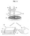
- FIG. 5is an illustration showing a configuration of a skin permeable gas-collecting device (sampling probe) according to a fourth example of the present invention.
- reference numeral 31represents a cylindrical member having a spiral groove 32
- reference numeral 33represents a cover placed on the upper face of the cylindrical member 31
- reference numeral 34represents a gas-introducing section connected to the cover 33
- reference numeral 35represents a gas delivery section connected to the cover 33
- reference numeral 40represents a sealing member, connected to the cylindrical member, for sealing the groove 32 of the cylindrical member 31 and for maintaining air contained in the groove 32 at a predetermined temperature
- reference numeral 41represents a heat sink
- reference numeral 42represents a Peltier element for adjusting the temperature of the contained air
- reference numeral 43represents a silicon coating
- reference numeral 44represents a Teflon sheet for sealing the groove 32 containing the air.
- Air in a laboratory roomis introduced into the cylindrical member 31 from the gas-introducing section 34 and then stored therein, the temperature of the introduced air is adjusted to a predetermined value with the Peltier element 42, and the resulting air is delivered through the gas delivery section 35, thereby subjecting the air (probe blank) to measurement.
- the sealing member 40 connected to the cylindrical memberin the situation, the bottom face of the cylindrical member 31 is pressed against skin of a subject 45 to collect skin permeable gas in the groove 32 of the cylindrical member 31 in a sealed manner while the above situation is maintained except that the sealing member 40 of the cylindrical member is not used.
- the collected skin permeable gasis delivered together with air through the gas delivery section 35 and is then subjected to measurement.
- Table 1shows the measurement result.
- Human Value Obtained from Measuring ToolAir Only
- Value Obtained from Human SkinAir + Skin Permeable Gas
- Actual Quantity Obtained from Human Skina 1.8 4.4 2.6 b 3.3 7.6 4.3 c** 3.1 11.7 8.6 d** 4.5 14.0 9.5 e** 3.9 9.1 5.2 f 4.9 7.7 2.8 g** 2.0 12.6 10.6
- the air quantity obtained from a measuring toolis 1.8 ng
- the total quantity of air and acetoneis 4.4 ng
- the acetonebeing skin permeable gas emanating from the subject.
- the quantity of acetone gas emanating from the skin surface of the subjectis 2.6 ng.
- sampling data obtained from skinhas a higher value than that of the probe blank.
- the acetone content in 50 ml, 25 ml, and 10 ml of room airis 5.8, 2.8, and 1.3 ng, respectively. Since the volume of the sampling probe is 3.8 ml, the quantity of contaminants leaking from the surroundings is 0.5 ng or less.
- the acetone content in air of the laboratory roomis substantially equal to that in room air in a reinforced concrete building.
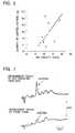
- FIG. 6is an illustration showing the relationship between the quantity of emitted acetone and BMI (body mass index, defined as the formula: body weight (kg) / (body height (m)) 2 ), wherein the acetone quantity is obtained with a device of the present invention and BMI is an obesity index.
- body mass indexdefined as the formula: body weight (kg) / (body height (m)) 2
- Gas collected from a human skin surfaceis analyzed by, for example, chromatography.
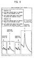
- FIG. 7is an illustration showing the result of chromatography analysis of a probe blank of the present invention which is obtained by performing sampling inside a left forearm for one minute.
- the upper section of FIG. 7is an illustration showing the result of the chromatography analysis of gas obtained by performing sampling inside a left forearm for ten minutes using a skin permeable gas-collecting device of the present invention.
- the lower section of FIG. 7is an illustration showing the result of the chromatography analysis of the probe blank. It is clear from this figure that the quantity of the skin permeable gas emanating from the human skin surface is larger than that of the gas remaining in the surroundings and the probe blank.
- FIGS. 8 to 11are illustrations showing the relationship between the ingestion of milk and the quantity of emitted hydrogen gas collected with a skin permeable gas-collecting device of the present invention; between the ingestion of milk and the quantity of the hydrogen gas in expired gas after the ingestion of milk.
- the illustrationsshow chromatograms obtained by measuring the hydrogen content in the following cases: an expired gas and a gas obtained from the left hand of Subject A (before the drinking of milk and after four hours following the drinking of the milk) and an expired gas and a gas obtained from the left hand of Subject B (before the drinking of milk and after four hours following the drinking of the milk).
- FIG. 8is an illustration showing chromatograms of hydrogen contained in expired gas.
- Chromatogram ais obtained by measuring the hydrogen content in expired gas of Subject A before the drinking of milk
- Chromatogram bis obtained by measuring the hydrogen content in expired gas of Subject A after the drinking of milk.
- Chromatograms (a) and (c)are obtained with a sensitivity of 5 mV
- Chromatograms (b) and (d)are obtained with a sensitivity of 100 mV.
- FIG. 9is an illustration showing the analysis results of skin permeable gas obtained from left hands for ten minutes. The gas was obtained after about four hours since subjects had drunk milk. In FIG. 9, the sensitivity is 2 mV.
- the hydrogen content in expired gas of Subject Aincreases from 2 to 7 ppm
- the hydrogen content in expired gas of Subject Bincreases from 1 to 91 ppm
- the hydrogen content in gas emanating from the left hand of Subject Aincreases from 0.003 to 0.08 ppm
- the hydrogen content in gas emanating from the left hand of Subject Bincreases from 0.07 to 0.41 ppm.
- FIGS. 10 and 11are illustrations showing a correlation between expired gas and skin permeable gas. There is a obvious correlation for hydrogen, which suggests that diagnosis using the skin permeable gas is possible.
- FIG. 12is an illustration showing a configuration of a skin permeable gas-measuring apparatus according to a fifth example of the present invention.
- reference numeral 50represents a skin permeable gas-measuring apparatus
- reference numeral 51represents a skin permeable gas-collecting chamber
- reference numeral 52represents a circulating chamber
- reference numeral 53represents a blower fan
- reference numeral 54represents various coloring agents A, B, C
- reference numeral 55represents skin of a subject.
- skin permeable gasis collected on the skin 55, the collected skin permeable gas is then immediately circulated to allow the gas to pass through the various coloring agents 54, thereby detecting specific gas.
- the subjectcan obtain the measurement result on the spot.
- Information processing of a sampling detection system disposed on skincan be performed with a computer, which is not shown.
- gas replacementis sufficiently performed. That is, it is critical that used gas is removed by ventilation and sample gas is collected while the sample gas is successively discharged.
- a correlation between skin permeable gas and morbidityis as follows.
- the skin permeable gashas a correlation with diabetes, obesity, and autointoxication when the skin permeable gas is acetone, and the skin permeable gas has a quantitative correlation with the presence of enteric bacteria that decompose lactose when the skin permeable gas is hydrogen.
- the skin permeable gashas a correlation with uremia, liver failure, abdominal abscess, and the presence of helicobacter pylori when the skin permeable gas is ammonia.
- the measurement of the skin permeable gas according to the present inventioncan be contribute to the diagnosis of various types of morbidity.
- a skin permeable gas-collecting device and skin permeable gas-measuring apparatus of the present inventionare useful for clinical measurement using skin permeable gas and useful in determining human health condition.
- Such a device and apparatuscan be miniaturized and are fit for the simple diagnosis of various types of morbidity.
Landscapes
- Health & Medical Sciences (AREA)
- Life Sciences & Earth Sciences (AREA)
- Physics & Mathematics (AREA)
- General Health & Medical Sciences (AREA)
- Engineering & Computer Science (AREA)
- Biomedical Technology (AREA)
- Molecular Biology (AREA)
- Pathology (AREA)
- Animal Behavior & Ethology (AREA)
- Heart & Thoracic Surgery (AREA)
- Veterinary Medicine (AREA)
- Public Health (AREA)
- Surgery (AREA)
- Medical Informatics (AREA)
- Biophysics (AREA)
- Optics & Photonics (AREA)
- Biochemistry (AREA)
- Analytical Chemistry (AREA)
- Chemical & Material Sciences (AREA)
- Immunology (AREA)
- General Physics & Mathematics (AREA)
- Dermatology (AREA)
- Sampling And Sample Adjustment (AREA)
- Investigating Or Analysing Biological Materials (AREA)
- Measurement Of The Respiration, Hearing Ability, Form, And Blood Characteristics Of Living Organisms (AREA)
- Measuring And Recording Apparatus For Diagnosis (AREA)
Abstract
Description
- The present invention relates to a device for collecting skin permeable gas and an apparatus for measuring such skin permeable gas, wherein the device and apparatus are used to determine the health condition of subjects.
- Conventionally, blood and human metabolites (urine and feces) have been major clinical items used for determining human health condition. Recently, saliva and expired gas have been becoming test objects, and sweat will be also included in such clinical items in future. Components of such expired gas, saliva, and sweat depend on components of blood and thus there is quantitative relationship between both the components. It is expected that these noninvasive metabolites be used in the field of in-home medical care and health management in future.
- There have been no measuring equipment used for clinical measurement and no measuring equipment for determining human health condition using such skin permeable gas. This is because the existence of the skin permeable gas itself has not been assumed for such purposes.
- Document
US-A-4 439 679 disclosed a device as described in the preambule ofclaim 1. - The invention is as disclosed in the appended set of claims.
- As described above, the inventors have found that skin permeable gas depends on components of blood in peripheral blood vessels. The inventors have also found that the skin permeable gas is extremely important in determining new types of morbidity.
- In view of the above situation, it is an object of the present invention to provide an apparatus for measuring the skin permeable gas, wherein such an apparatus can be used to obtain clinical information by noninvasive and bloodless operations and is useful for in-home medical care and health management.
- In order to achieve the above object, the following devices and apparatus are provided.
- (1) A skin permeable gas-collecting device including a container having an opening section and including a storing means for storing skin permeable gas emanating from skin, the skin permeable gas being obtained by bringing the opening section into intimate contact with the skin; and a delivery means for delivering the skin gas stored in the container.
- (2) The skin permeable gas-collecting device further including a partition, disposed at a lower section inside the container, having an opening at the center thereof; and an operating member for opening and closing the opening of the partition.
- (3) The skin permeable gas-collecting device, wherein the container includes a first sub-container, having a hole, for storing the skin permeable gas; a second sub-container that surrounds the first sub-container and is brought into intimate contact with the skin by decompression obtained by removing air; and a delivery unit for delivering the skin permeable gas stored in the first sub-container.
- (4) A skin permeable gas-collecting device including a finger-stall including a coupler, and one or more connections that are connectable with the coupler and include a stopcock.
- (5) A skin permeable gas-collecting device including a cylindrical member including a spiral groove, a cover disposed on the upper surface of the cylindrical member, a gas-introducing section connected to the cover, a gas delivery section connected to the cover, and a sealing member for sealing the groove of the cylindrical member and for maintaining air contained in the groove at a predetermined temperature, wherein, after components in the air maintained at a predetermined temperature are analyzed, the sealing member is detached from the cylindrical member and the cylindrical member from which the sealing member is detached is then brought into intimate contact with skin of a subject to collect the skin permeable gas.
- (6) A skin permeable gas-measuring apparatus including a first container, having an opening, for storing skin permeable gas; a blower fan for circulating the stored skin permeable gas; and a measuring unit including a coloring agent placed in a path through which the gas is circulated with the blower fan.
- FIG. 1 is an illustration showing a configuration of a skin permeable gas-collecting device according to a first example of the present invention.
- FIG. 2 is an illustration showing a configuration of a skin permeable gas-collecting device according to a second example of the present invention.
- FIG. 3 is an illustration showing a configuration of a skin permeable gas-collecting device according to a third example of the present invention.
- FIG. 4 is an illustration showing a comparison between the acetone content in expired gas and the acetone content in vapor emanating from a left index finger.
- FIG. 5 is an illustration showing a configuration of a skin permeable gas-collecting device (sampling probe) according to a fourth example of the present invention.
- FIG. 6 is an illustration showing the relationship between the quantity of emitted acetone and BMI, wherein the acetone quantity is obtained with a device of the present invention and BMI is an obesity index.
- FIG. 7 is an illustration showing chromatograms of a probe blank of the present invention which is obtained by performing sampling inside a left forearm for ten minutes.
- FIG. 8 is an illustration (first illustration) showing the relationship between the ingestion of milk and the quantity of emitted hydrogen gas collected with a skin permeable gas-collecting device of the present invention; between the ingestion of milk and the quantity of the hydrogen gas in expired gas after the ingestion of milk.
- FIG. 9 is an illustration (second illustration) showing the relationship between the ingestion of milk and the quantity of emitted hydrogen gas collected with a skin permeable gas-collecting device of the present invention; between the ingestion of milk and the quantity of the hydrogen gas in expired gas after the injection of milk.
- FIG. 10 is an illustration (third illustration) showing the relationship between the ingestion of milk and the quantity of emitted hydrogen gas collected with a skin permeable gas-collecting device of the present invention; between the ingestion of milk and the quantity of the hydrogen gas in expired gas after the ingestion of milk.
- FIG. 11 is an illustration (fourth illustration) showing the relationship between the ingestion of milk and the quantity of emitted hydrogen gas collected with a skin permeable gas-collecting device of the present invention; between the ingestion of milk and the quantity of the hydrogen gas in expired gas after the ingestion of milk.
- FIG. 12 is an illustration showing a configuration of a skin permeable gas-measuring apparatus according to a fifth example of the present invention.
- Embodiments of the present invention will now be described in detail with reference to the accompanying drawings.
- FIG. 1 is an illustration showing a configuration of a skin permeable gas-collecting device according to a first example of the present invention. FIG. 1(a) is a perspective view showing the outline thereof, FIG. 1(b) is an illustration showing such a state that a lower chamber of the skin permeable gas-collecting device is filled with skin permeable gas, FIG. 1(c) is an illustration showing such a state that the skin permeable gas is allowed to flow into an upper chamber from the lower chamber, and FIG. 1(d) is an illustration showing such a state that the upper chamber filled with the skin permeable gas is sealed.
- In these figures,
reference numeral 1 represents a container of the skin permeable gas-collecting device;reference numeral 1A represents a lower chamber disposed in thecontainer 1;reference numeral 1B represents an upper chamber disposed in thecontainer 1;reference numeral 2 represents a partition plate, disposed at a lower position inside thecontainer 1, having anopening 2A at the center thereof;reference numeral 3 represents an operating member capable of opening and closing theopening 2A of thepartition plate 2;reference numeral 4 represents a knob disposed at the upper end of theoperating member 3;reference numeral 5 represents a rod of theoperating member 3;reference numeral 6 represents a valve member disposed at the lower end of therod 5;reference numeral 7 represents an O-ring for sealing a gap between thecontainer 1 and therod 5;reference numeral 8 represents a ventilation port, connected to thecontainer 1, for removing the skin permeable gas;reference numeral 9 represents a delivery port, connected to thecontainer 1, for removing the skin permeable gas; andreference numeral 10 represents skin of a subject. - The operation of this device is described below.
- As shown in FIG. 1(b), the
container 1 of the skin permeable gas-collecting device is pressed against thesubject skin 10 and then fixed thereto in such a state that theoperating member 3 is pressed downward and thereby the opening 2A of thepartition plate 2 is stopped up with thevalve member 6. In such a state, skin permeable gas emanating from thesubject skin 10 is collected in thelower chamber 1A. The ventilation port and thedelivery port 9 for removing the skin permeable gas are closed, wherein the ventilation port and thedelivery port 9 are connected to thecontainer 1. - After the collection of the skin permeable gas is finished, the
operating member 3 is drawn up to open the opening 2A of thepartition plate 2, as shown in FIG. 1(c). Thereby, the skin permeable gas collected in thelower chamber 1A is allowed to flow into theupper chamber 1B. - As shown in FIG. 1(d), the
operating member 3 is pressed down again to close the opening 2A of thepartition plate 2 and thereby the skin permeable gas is trapped and stored in theupper chamber 1B. - The
delivery port 9 for the skin permeable gas is opened, theventilation port 8 is also opened, and gas is fed from theventilation port 8 to force the skin permeable gas out, thereby subjecting the skin permeable gas to measurement. This procedure, however, is not shown in the figure. - FIG. 2 is an illustration showing a configuration of a skin permeable gas-collecting device according to a second example of the present invention.
- In this figure,
reference numeral 11 represents a first container for storing the skin permeable gas;reference numeral 12 represents a second container, surrounding thefirst container 11 for removing air to provide decompression to bring thefirst container 11 into intimate contact with skin;reference numeral 13 represents an evacuation unit, connected to thesecond container 12, for removing gas;reference numeral 14 represents a cock;reference numeral 15 represents a gas-introducing unit connected to thefirst container 11;reference numeral 16 represents a delivery unit, connected to thefirst container 11, for removing the skin permeable gas; andreference numeral 17 represents skin of a subject. - According to the above configuration, after the
delivery unit 16 is closed and the gas-introducingunit 15 is opened to introduce gas (dry air) into thefirst container 11, the gas-introducingunit 15 is closed to collect the skin permeable gas from thesubject skin 17. After the skin permeable gas is collected, thedelivery unit 16 is opened to deliver the skin permeable gas into a test container (not shown). - In this case, in order to bring the
first container 11 into intimate contact with thesubject skin 17, the container section has dual structure. In particular, thesecond container 12 arranged outside thefirst container 11 is decompressed with theevacuation unit 13, thereby bringing thefirst container 11 into intimate contact with the skin. - FIG. 3 is an illustration showing a configuration of a skin permeable gas-collecting device according to a third example of the present invention. FIG. 3(a) is an illustration showing a finger-stall and an injection syringe connected thereto, FIG. 3(b) is an illustration showing such a situation that a finger is fitted into the finger-stall, FIG. 3(c) is an illustration showing such a situation that the finger-stall is filled with air fed from the injection syringe, and FIG. 3(d) is an illustration showing such a situation that the air and skin permeable gas are inhaled.
- In these figures,
reference numeral 21 represents a finger-stall (a bag made from Teflon),reference numeral 22 represents a coupler (for example, a cock),reference numeral 23 represents an injection syringe (100 ml),reference numeral 24 represents a stopcock,reference numeral 25 represents rubber or a clip provided on the outside of the base of the finger-stall 22,reference numeral 26 represents a finger of a subject,reference numeral 27 represents a gas-introducing unit, andreference numeral 28 represents the inflated finger-stall filled with air. - According to this example, the skin permeable gas can be recovered by the following methods.
- As shown in FIG. 3(a), the following tools are prepared: the finger-
stall 21 having thecock 22 at the tip thereof and theinjection syringe 23, connectable to thecock 22, including thestopcock 24. As shown in FIG. 3(b), thefinger 26 is fitted into the finger-stall 21. As shown in FIG. 3(c), thestopcock 24 is opened, thecock 22 is then opened to introduce gas (dry air) from theinjection syringe 23, the finger-stall 21 is inflated and then sealed, and thestopcock 24 is then closed. Subsequently, the skin permeable gas is collected from thesubject finger 26. After the collection of the skin permeable gas, thestopcock 24 is opened to deliver (recover) the collected skin permeable gas intoinjection syringe 23 through thecock 22. - As shown in FIG. 3(a), the following tools are prepared: the finger-
stall 21 having thecock 22 at the tip thereof and theinjection syringe 23, connectable to thecock 22, including thestopcock 24. As shown in FIG. 3(b), thefinger 26 is fitted into the finger-stall 21. As shown in FIG. 3(c), thestopcock 24 is closed, the gas-introducingunit 27 is opened to introduce gas (dry air), the finger-stall 21 is inflated and then sealed, thereby collecting the skin permeable gas. After the collection of the skin permeable gas, thestopcock 24 is opened to recover the collected skin permeable gas intoinjection syringe 23 through thecock 22. - As shown in FIG. 3(a), the following tools are prepared: the finger-
stall 21 having thecock 22 at the tip thereof and theinjection syringe 23, connectable to thecock 22, including thestopcock 24. As shown in FIG. 3(b), thefinger 26 is fitted into the finger-stall 21. As shown in FIG. 3(c), thestopcock 24 is opened, and the skin permeable gas is collected in theinjection syringe 23 while the gas-introducingunit 27 is opened to introduce gas (dry air) . - The collecting procedure is not limited to the above methods. Various modifications including the following procedures may be performed: a procedure in which gas is introduced from the
cock 22 to collect the skin permeable gas and the skin permeable gas is then recovered (delivered) into theinjection syringe 23 and a procedure in which gas is introduced from the gas-introducingunit 27 to collect the skin permeable gas and the skin permeable gas is then recovered through thecock 22. - According to the above configuration, emitted gas can be readily collected from the body skin surface, for example, the finger skin surface, which is herein used, and then recovered (delivered).
- Examples according to the collecting procedure will now be described.
- FIG. 4 is an illustration showing a comparison between the acetone content in expired gas and the acetone content in vapor emanating from a left index finger.
- Acetone emanating from the left index finger was collected and the expired gas was also collected at the time when the acetone sampling is stated. The comparison result of the acetone content is shown in FIG. 4. As shown in this figure, there is a positive correlation between the acetone content in the expired gas and the acetone content in the vapor emanating from the left index finger.
- When the acetone emanating from the left index finger was collected according to the above procedure and then determined, the outside air was used in this procedure. This is because the outside air inevitably leaks into the finger-stall when the finger is fitted into the finger-stall during the sampling.
- This procedure was employed on the premise that the acetone content in the outside air does not change for a short period (within 30 minutes). Since the acetone content does not inevitably remain constant in actual, this procedure for determining the acetone content is not precise if a change in the acetone content exceeds allowable limits. In order to solve this problem, the following finger-stall and sampling procedure must be employed: a finger-stall into which the outside air does not leak when a finger is fitted into or drawn out of the finger-stall, and a sampling procedure using such a finger-stall.
- FIG. 5 is an illustration showing a configuration of a skin permeable gas-collecting device (sampling probe) according to a fourth example of the present invention.
- In this figure,
reference numeral 31 represents a cylindrical member having aspiral groove 32;reference numeral 33 represents a cover placed on the upper face of thecylindrical member 31;reference numeral 34 represents a gas-introducing section connected to thecover 33;reference numeral 35 represents a gas delivery section connected to thecover 33;reference numeral 40 represents a sealing member, connected to the cylindrical member, for sealing thegroove 32 of thecylindrical member 31 and for maintaining air contained in thegroove 32 at a predetermined temperature;reference numeral 41 represents a heat sink;reference numeral 42 represents a Peltier element for adjusting the temperature of the contained air;reference numeral 43 represents a silicon coating; andreference numeral 44 represents a Teflon sheet for sealing thegroove 32 containing the air. - Air in a laboratory room is introduced into the
cylindrical member 31 from the gas-introducingsection 34 and then stored therein, the temperature of the introduced air is adjusted to a predetermined value with thePeltier element 42, and the resulting air is delivered through thegas delivery section 35, thereby subjecting the air (probe blank) to measurement. Replacing the sealingmember 40 connected to the cylindrical member in the situation, the bottom face of thecylindrical member 31 is pressed against skin of a subject 45 to collect skin permeable gas in thegroove 32 of thecylindrical member 31 in a sealed manner while the above situation is maintained except that the sealingmember 40 of the cylindrical member is not used. The collected skin permeable gas is delivered together with air through thegas delivery section 35 and is then subjected to measurement. - The measurement result is described below.
Table 1 shows the measurement result. Human Value Obtained from Measuring Tool (Air Only) Value Obtained from Human Skin (Air + Skin Permeable Gas) Actual Quantity Obtained from Human Skin a 1.8 4.4 2.6 b 3.3 7.6 4.3 c** 3.1 11.7 8.6 d** 4.5 14.0 9.5 e** 3.9 9.1 5.2 f 4.9 7.7 2.8 g** 2.0 12.6 10.6 - As shown in this table, for Subject a, the air quantity obtained from a measuring tool is 1.8 ng, and the total quantity of air and acetone is 4.4 ng, the acetone being skin permeable gas emanating from the subject. Thus, the quantity of acetone gas emanating from the skin surface of the subject is 2.6 ng. In any subject, sampling data obtained from skin has a higher value than that of the probe blank.
- The acetone content in 50 ml, 25 ml, and 10 ml of room air is 5.8, 2.8, and 1.3 ng, respectively. Since the volume of the sampling probe is 3.8 ml, the quantity of contaminants leaking from the surroundings is 0.5 ng or less. The acetone content in air of the laboratory room is substantially equal to that in room air in a reinforced concrete building.
- It can be inferred from the above result that the quantity of acetone emanating from a human skin surface can be measured with this experiment means.
- FIG. 6 is an illustration showing the relationship between the quantity of emitted acetone and BMI (body mass index, defined as the formula: body weight (kg) / (body height (m))2), wherein the acetone quantity is obtained with a device of the present invention and BMI is an obesity index.
- It is clear from this figure that there is a positive correlation between the obesity index (BMI) and the quantity of emitted acetone.
- Gas collected from a human skin surface is analyzed by, for example, chromatography.
- FIG. 7 is an illustration showing the result of chromatography analysis of a probe blank of the present invention which is obtained by performing sampling inside a left forearm for one minute. The upper section of FIG. 7 is an illustration showing the result of the chromatography analysis of gas obtained by performing sampling inside a left forearm for ten minutes using a skin permeable gas-collecting device of the present invention. The lower section of FIG. 7 is an illustration showing the result of the chromatography analysis of the probe blank. It is clear from this figure that the quantity of the skin permeable gas emanating from the human skin surface is larger than that of the gas remaining in the surroundings and the probe blank.
- FIGS. 8 to 11 are illustrations showing the relationship between the ingestion of milk and the quantity of emitted hydrogen gas collected with a skin permeable gas-collecting device of the present invention; between the ingestion of milk and the quantity of the hydrogen gas in expired gas after the ingestion of milk. The illustrations show chromatograms obtained by measuring the hydrogen content in the following cases: an expired gas and a gas obtained from the left hand of Subject A (before the drinking of milk and after four hours following the drinking of the milk) and an expired gas and a gas obtained from the left hand of Subject B (before the drinking of milk and after four hours following the drinking of the milk).
- FIG. 8 is an illustration showing chromatograms of hydrogen contained in expired gas. Chromatogram a is obtained by measuring the hydrogen content in expired gas of Subject A before the drinking of milk, and Chromatogram b is obtained by measuring the hydrogen content in expired gas of Subject A after the drinking of milk. In FIG. 8, Chromatograms (a) and (c) are obtained with a sensitivity of 5 mV and Chromatograms (b) and (d) are obtained with a sensitivity of 100 mV.
- FIG. 9 is an illustration showing the analysis results of skin permeable gas obtained from left hands for ten minutes. The gas was obtained after about four hours since subjects had drunk milk. In FIG. 9, the sensitivity is 2 mV.
- It is clear from these figures that human skin surface emanates hydrogen and the hydrogen can be detected using a device of the present invention. It is found that the correlation between the ingest of milk and the hydrogen emanation can be clarified.
- When the hydrogen content in gas obtained before the drinking of milk is compared with the hydrogen content in gas obtained after about four hours following the drinking of milk, the following results are obtained: the hydrogen content in expired gas of Subject A increases from 2 to 7 ppm, the hydrogen content in expired gas of Subject B increases from 1 to 91 ppm, the hydrogen content in gas emanating from the left hand of Subject A increases from 0.003 to 0.08 ppm, and the hydrogen content in gas emanating from the left hand of Subject B increases from 0.07 to 0.41 ppm. Thus, it is clear that an increase in hydrogen in not only expired gas but also gas emanating from a left hand is caused by the drinking of milk. Furthermore, it is clear from this measurement that there is an extremely high correlation between the hydrogen content in expired gas and the hydrogen content in gas emanating from skin.
- FIGS. 10 and 11 are illustrations showing a correlation between expired gas and skin permeable gas. There is a obvious correlation for hydrogen, which suggests that diagnosis using the skin permeable gas is possible.
- FIG. 12 is an illustration showing a configuration of a skin permeable gas-measuring apparatus according to a fifth example of the present invention.
- In this figure,
reference numeral 50 represents a skin permeable gas-measuring apparatus,reference numeral 51 represents a skin permeable gas-collecting chamber,reference numeral 52 represents a circulating chamber,reference numeral 53 represents a blower fan,reference numeral 54 represents various coloring agents A, B, C, andreference numeral 55 represents skin of a subject. - As shown in this figure, skin permeable gas is collected on the
skin 55, the collected skin permeable gas is then immediately circulated to allow the gas to pass through thevarious coloring agents 54, thereby detecting specific gas. Thus, the subject can obtain the measurement result on the spot. - Information processing of a sampling detection system disposed on skin can be performed with a computer, which is not shown.
- In order to prevent gas from being absorbed in H2O in sweat, gas replacement is sufficiently performed. That is, it is critical that used gas is removed by ventilation and sample gas is collected while the sample gas is successively discharged.
- The use of the present invention is described below.
- A correlation between skin permeable gas and morbidity is as follows. The skin permeable gas has a correlation with diabetes, obesity, and autointoxication when the skin permeable gas is acetone, and the skin permeable gas has a quantitative correlation with the presence of enteric bacteria that decompose lactose when the skin permeable gas is hydrogen. Furthermore, the skin permeable gas has a correlation with uremia, liver failure, abdominal abscess, and the presence of helicobacter pylori when the skin permeable gas is ammonia. As described above, the measurement of the skin permeable gas according to the present invention can be contribute to the diagnosis of various types of morbidity.
- It should be understood that the present invention is not limited to the above examples and various modifications may be performed within the scope of the present invention. The present invention is intended to cover such modifications.
- As described above in detail, according to the present invention, the following advantages can be obtained.
- (A) Clinical information that are useful for in-home medical care and health management can be obtained by noninvasive and bloodless operations.
- (B) Skin permeable gas emanating from skin surface can be readily collected and the species and quantity of such gas can be analyzed.
- (C) Collected gas can be readily stored in a sealed manner and then transported to a measuring apparatus.
- (D) Secure attachment to skin is possible.
- (E) Contaminants contained in the space of a cylindrical member and/or leaking from the surroundings can be measured in advance and therefore the skin permeable gas can be precisely analyzed.
- (F) When a spiral groove is placed, the quantity of collected gas per unit area of skin can be increased and thus the skin permeable gas can be efficiently collected.
- (G) The miniaturization of a device and apparatus is possible.
- As described above, a skin permeable gas-collecting device and skin permeable gas-measuring apparatus of the present invention are useful for clinical measurement using skin permeable gas and useful in determining human health condition. Such a device and apparatus can be miniaturized and are fit for the simple diagnosis of various types of morbidity.
Claims (1)
- (Amended) A device for collecting skin permeable gas, comprising a container having an opening section, the opening section being brought into intimate contact with skin to collect emitted skin permeable gas, the collected skin permeable, gas being delivered and then measured,
characterized in that the container includes an upper chamber, having a hole, for storing skin permeable gas; a lower chamber that is brought into intimate contact with the skin; a partition, having an opening at the center thereof, for separating the upper chamber from the lower chamber; and a push-pull operating member for controlling the flow of the skin permeable gas flowing between the lower chamber and the upper chamber, where the lower chamber is pressed against the skin and then fixed thereto in such a state that the operating member is pressed down to close the opening of the partition using a valve member disposed at the lower end of the operating member, the skin permeable gas emanating from the skin is collected in the lower chamber, the valve member of the operating member is drawn up after the collection to open the opening of the partition to allow the skin permeable gas collected in the lower chamber to flow into the upper chamber, the valve member of the operating member is then pressed down after a predetermined time to close the opening of the partition to store the skin permeable gas.
Priority Applications (3)
| Application Number | Priority Date | Filing Date | Title |
|---|---|---|---|
| EP06021705AEP1764032A3 (en) | 2000-12-27 | 2001-12-26 | Skin permeable gas collector and skin permeable gas measuring apparatus |
| EP06021707AEP1746406B1 (en) | 2000-12-27 | 2001-12-26 | Skin permeable gas collector and skin permeable gas measuring apparatus |
| EP06021706AEP1746405A3 (en) | 2000-12-27 | 2001-12-26 | Skin permeable gas collector and skin permeable gas measuring apparatus |
Applications Claiming Priority (3)
| Application Number | Priority Date | Filing Date | Title |
|---|---|---|---|
| JP2000396949AJP3850662B2 (en) | 2000-12-27 | 2000-12-27 | Skin permeation gas collection device |
| JP2000396949 | 2000-12-27 | ||
| PCT/JP2001/011435WO2002054041A1 (en) | 2000-12-27 | 2001-12-26 | Skin permeable gas collector and skin permeable gas measuring apparatus |
Related Child Applications (3)
| Application Number | Title | Priority Date | Filing Date |
|---|---|---|---|
| EP06021705ADivisionEP1764032A3 (en) | 2000-12-27 | 2001-12-26 | Skin permeable gas collector and skin permeable gas measuring apparatus |
| EP06021707ADivisionEP1746406B1 (en) | 2000-12-27 | 2001-12-26 | Skin permeable gas collector and skin permeable gas measuring apparatus |
| EP06021706ADivisionEP1746405A3 (en) | 2000-12-27 | 2001-12-26 | Skin permeable gas collector and skin permeable gas measuring apparatus |
Publications (3)
| Publication Number | Publication Date |
|---|---|
| EP1357376A1 EP1357376A1 (en) | 2003-10-29 |
| EP1357376A4 EP1357376A4 (en) | 2005-11-30 |
| EP1357376B1true EP1357376B1 (en) | 2007-10-31 |
Family
ID=18862156
Family Applications (4)
| Application Number | Title | Priority Date | Filing Date |
|---|---|---|---|
| EP06021706AWithdrawnEP1746405A3 (en) | 2000-12-27 | 2001-12-26 | Skin permeable gas collector and skin permeable gas measuring apparatus |
| EP01995011AExpired - LifetimeEP1357376B1 (en) | 2000-12-27 | 2001-12-26 | Skin permeable gas collector |
| EP06021705AWithdrawnEP1764032A3 (en) | 2000-12-27 | 2001-12-26 | Skin permeable gas collector and skin permeable gas measuring apparatus |
| EP06021707AExpired - LifetimeEP1746406B1 (en) | 2000-12-27 | 2001-12-26 | Skin permeable gas collector and skin permeable gas measuring apparatus |
Family Applications Before (1)
| Application Number | Title | Priority Date | Filing Date |
|---|---|---|---|
| EP06021706AWithdrawnEP1746405A3 (en) | 2000-12-27 | 2001-12-26 | Skin permeable gas collector and skin permeable gas measuring apparatus |
Family Applications After (2)
| Application Number | Title | Priority Date | Filing Date |
|---|---|---|---|
| EP06021705AWithdrawnEP1764032A3 (en) | 2000-12-27 | 2001-12-26 | Skin permeable gas collector and skin permeable gas measuring apparatus |
| EP06021707AExpired - LifetimeEP1746406B1 (en) | 2000-12-27 | 2001-12-26 | Skin permeable gas collector and skin permeable gas measuring apparatus |
Country Status (6)
| Country | Link |
|---|---|
| US (4) | US7261692B2 (en) |
| EP (4) | EP1746405A3 (en) |
| JP (1) | JP3850662B2 (en) |
| KR (4) | KR100572548B1 (en) |
| DE (2) | DE60136664D1 (en) |
| WO (1) | WO2002054041A1 (en) |
Families Citing this family (21)
| Publication number | Priority date | Publication date | Assignee | Title |
|---|---|---|---|---|
| GB0223274D0 (en)* | 2002-10-08 | 2002-11-13 | South Bank Univ Entpr Ltd | Method and equipment for measuring vapour flux from surfaces |
| JP4654045B2 (en)* | 2005-02-01 | 2011-03-16 | 学校法人東海大学 | Skin gas collector |
| WO2007115568A1 (en)* | 2006-04-07 | 2007-10-18 | Radiometer Medical Aps | Mounting device for an electrochemical sensor unit |
| US20080160638A1 (en)* | 2006-12-27 | 2008-07-03 | David Lederman | Functionalized Microcantilever Sensor and Associated Method For Detection of Targeted Analytes |
| JP5099345B2 (en)* | 2008-01-25 | 2012-12-19 | 有限会社ピコデバイス | Method and apparatus for sensing drinking alcohol using skin gas |
| JP5412609B2 (en)* | 2008-08-27 | 2014-02-12 | 国立大学法人 名古屋工業大学 | A method and apparatus for measuring the metabolic state of an animal individual. |
| JP2010148692A (en)* | 2008-12-25 | 2010-07-08 | National Cardiovascular Center | Method and apparatus for detecting surface gas |
| US8687860B2 (en)* | 2009-11-24 | 2014-04-01 | Penrad Technologies, Inc. | Mammography statistical diagnostic profiler and prediction system |
| JP2013088115A (en)* | 2011-10-13 | 2013-05-13 | Canon Inc | Skin gas sampler |
| BR112014027986A2 (en)* | 2012-05-10 | 2017-06-27 | Unilever Nv | skin surface sampling device and system |
| JP2014010046A (en)* | 2012-06-29 | 2014-01-20 | Seiko Epson Corp | Substance detection device and wrist watch type body fat burning measurement device |
| JP6227934B2 (en)* | 2013-08-23 | 2017-11-08 | 株式会社Nttドコモ | Gas measuring device and gas measuring method |
| CN103462649B (en)* | 2013-09-22 | 2015-01-07 | 温州医学院附属第二医院 | Special dropper for skin prick test |
| CN104398273A (en)* | 2014-12-04 | 2015-03-11 | 刘道义 | Pathological collecting board |
| CA2973261A1 (en) | 2015-01-09 | 2016-07-14 | Exhalix Llc | Transdermal sampling strip and method for analyzing transdermally emitted gases |
| CN104546025B (en)* | 2015-01-29 | 2017-01-25 | 丁德正 | Chuck dropper special for skin prick test |
| JP6523749B2 (en)* | 2015-04-01 | 2019-06-05 | 株式会社Nttドコモ | INFORMATION PROCESSING APPARATUS, INFORMATION PROCESSING METHOD, AND PROGRAM |
| JP7101968B2 (en)* | 2017-04-21 | 2022-07-19 | 特定非営利活動法人熟年体育大学リサーチセンター | Portable emission monitoring device |
| US20210361224A1 (en) | 2017-11-22 | 2021-11-25 | National University Corporation Tokyo Medical And Dental University | BIOLOGICAL GAS (VOCs) MEASURMENT DEVICE |
| CA3164715A1 (en)* | 2020-02-18 | 2021-08-26 | F. Hoffmann-La Roche Ag | Device for collection of volatile compounds from skin for non-invasive measurement of blood-glucose values |
| CN112156246A (en)* | 2020-10-16 | 2021-01-01 | 张岩 | Negative pressure drainage device for breast surgery |
Family Cites Families (55)
| Publication number | Priority date | Publication date | Assignee | Title |
|---|---|---|---|---|
| US1627974A (en)* | 1926-02-05 | 1927-05-10 | Himmerich Max | Stopcock |
| US2112580A (en)* | 1930-04-19 | 1938-03-29 | Fmc Corp | Method of coloring fruits |
| US2174349A (en)* | 1935-07-13 | 1939-09-26 | Mine Safety Appliances Co | Gas analysis |
| US2281625A (en)* | 1941-09-24 | 1942-05-05 | Bronson C Skinner | Method of coloring fruits and vegetables |
| US2567926A (en)* | 1946-03-01 | 1951-09-18 | Milton S Dunkelberger | Tubular supporting member |
| US3440806A (en)* | 1965-10-18 | 1969-04-29 | Carrier Corp | Separator tube cap |
| FR1482010A (en)* | 1966-02-14 | 1967-05-26 | Device for gas analysis | |
| US3659586A (en)* | 1969-05-20 | 1972-05-02 | Univ Johns Hopkins | Percutaneous carbon dioxide sensor and process for measuring pulmonary efficiency |
| US3649199A (en)* | 1970-03-26 | 1972-03-14 | Varian Associates | Method for detecting trace quantities of an organic drug material in a living animal |
| US3667918A (en)* | 1971-02-17 | 1972-06-06 | Pollution Monitors Inc | Method and apparatus for analysis of no and no2 |
| US3767552A (en)* | 1971-10-06 | 1973-10-23 | Teledyne Ind | Gas analyzer |
| US3799149A (en)* | 1972-12-26 | 1974-03-26 | Nasa | Metabolic analyzer |
| US3874552A (en)* | 1973-12-17 | 1975-04-01 | Gen Electric | Refrigerator apparatus |
| GB1509174A (en)* | 1974-04-05 | 1978-04-26 | Searle & Co | Device for measuring blood gases |
| DE2527706A1 (en)* | 1975-06-21 | 1976-12-30 | Hanfried Dr Med Weigand | DEVICE FOR THE INTRODUCTION OF CONTRAST AGENTS INTO AN ARTIFICIAL INTESTINAL OUTLET |
| GB2008200B (en)* | 1977-11-09 | 1982-10-20 | Emerit Andre A C | Source of vacuum and device for creating and maintaining anegative pressure in an enclosure |
| SE7811708L (en)* | 1977-11-15 | 1979-05-16 | Medishield Corp Ltd | TRANSCUTAN SOND |
| US4401122A (en)* | 1979-08-02 | 1983-08-30 | Children's Hospital Medical Center | Cutaneous methods of measuring body substances |
| US4439679A (en)* | 1981-04-10 | 1984-03-27 | The Regents Of The University Of California | Transcutaneous gas tension measurement using a dual sampling chamber and gas analysis system |
| JPS5988141A (en)* | 1982-11-12 | 1984-05-22 | 株式会社日立製作所 | Sample gas sampling measurement device |
| FI78231C (en)* | 1984-11-21 | 1989-07-10 | Instrumentarium Oy | Measuring device for metabolic quantities connectable to a respirator |
| JPH06119B2 (en)* | 1985-09-26 | 1994-01-05 | 株式会社日立製作所 | Transdermal sensor for detecting organic matter and electrolytes in sweat |
| US4691701A (en)* | 1986-07-28 | 1987-09-08 | Tudor Williams R | Carbon dioxide detector |
| DE3723881A1 (en)* | 1987-07-18 | 1989-01-26 | Nicolay Gmbh | METHOD FOR DETERMINING THE OXYGEN SATURATION OF THE BLOOD OF A LIVING ORGANISM AND ELECTRONIC CIRCUIT, AND DEVICE FOR CARRYING OUT THIS METHOD |
| JPH021105A (en) | 1988-06-07 | 1990-01-05 | Toshiba Corp | Manufacture of mask for ion beam exposure use |
| JPH021105U (en)* | 1988-06-15 | 1990-01-08 | ||
| US4896547A (en)* | 1988-11-18 | 1990-01-30 | Thermedics Inc. | Air-sampling apparatus with easy walk-in access |
| US5143080A (en)* | 1988-12-07 | 1992-09-01 | York Kenneth K | In vivo osmometer |
| JPH0348554A (en) | 1989-04-11 | 1991-03-01 | Oki Electric Ind Co Ltd | Packet switchboard |
| US4947861A (en)* | 1989-05-01 | 1990-08-14 | Hamilton Lyle H | Noninvasive diagnosis of gastritis and duodenitis |
| JP2700821B2 (en) | 1989-07-14 | 1998-01-21 | 内山工業株式会社 | Ethylene-acrylic rubber composition |
| US5131390A (en)* | 1989-09-14 | 1992-07-21 | Suzuken Co. | Device for continuously measuring the skin local sweating rate |
| US5120511A (en)* | 1990-10-05 | 1992-06-09 | Westvaco Corporation | Adsorber bed life monitor |
| US5140993A (en)* | 1991-12-27 | 1992-08-25 | Baylor College Of Medicine | Device for collecting a breath sample |
| JPH06119A (en) | 1992-06-17 | 1994-01-11 | Iida Kenchiku Sekkei Jimusho:Kk | Underfloor bed |
| US5285794A (en)* | 1992-12-14 | 1994-02-15 | Temple University Of The Commonwealth System Of Higher Education | Respiratory gas monitor |
| US5339810A (en)* | 1993-05-03 | 1994-08-23 | Marquette Electronics, Inc. | Pulse oximetry sensor |
| US5452717A (en)* | 1993-07-14 | 1995-09-26 | Masimo Corporation | Finger-cot probe |
| FI934211L (en)* | 1993-09-24 | 1995-03-25 | Instrumentarium Oy | Method for measuring gas exchange and metabolism |
| US5533512A (en)* | 1994-03-18 | 1996-07-09 | Ohmeda Inc. | Method and apparatus for detection of venous air emboli |
| AT401874B (en)* | 1995-01-04 | 1996-12-27 | Wimmer Erwin | SCRAPPING DEVICE FOR SCRAPPING TREATMENT OF SKIN AND BODY PARTS |
| JP2839865B2 (en)* | 1995-11-21 | 1998-12-16 | 株式会社ケーアンドエス | Local sweat measurement device |
| JP2964942B2 (en)* | 1996-02-28 | 1999-10-18 | 日本電気株式会社 | Suction leachate collection device |
| US5834626A (en)* | 1996-11-29 | 1998-11-10 | De Castro; Emory S. | Colorimetric indicators for breath, air, gas and vapor analyses and method of manufacture |
| US6712762B1 (en)* | 1997-02-28 | 2004-03-30 | Ors Diagnostic, Llc | Personal computer card for collection of real-time biological data |
| JP3047855B2 (en) | 1997-04-25 | 2000-06-05 | 日本電気株式会社 | WDM optical transmitter |
| DE19805654C2 (en)* | 1998-02-12 | 2000-06-29 | Draeger Medizintech Gmbh | Incubator with different tempered zones and method for tempering its interior |
| US6073499A (en)* | 1998-03-12 | 2000-06-13 | Penn State Research Foundation | Chemical trace detection portal based on the natural airflow and heat transfer of the human body |
| JP3048554B2 (en)* | 1998-04-08 | 2000-06-05 | 株式会社ケーアンドエス | Local transpiration measurement capsule |
| JPH11318874A (en)* | 1998-05-13 | 1999-11-24 | Takao Tsuda | A nerve function measurement device using active sweating as an index |
| US6126613A (en)* | 1999-02-08 | 2000-10-03 | Edwards; Raymond A. | Device and method to measure inhalation and exhalation air flows |
| US6287255B1 (en)* | 1999-10-15 | 2001-09-11 | Kao Corporation | Apparatus for measuring transpiration amount |
| MXPA02005068A (en)* | 1999-11-19 | 2002-11-07 | Spectrx Inc | Tissue interface device. |
| US6409679B2 (en)* | 2000-06-13 | 2002-06-25 | Pacific Paragon Investment Fund Ltd. | Apparatus and method for collecting bodily fluid |
| US7004909B1 (en)* | 2001-03-19 | 2006-02-28 | Pranalytica, Inc. | Diagnostic method for high sensitivity detection of component concentrations in human gas emissions |
- 2000
- 2000-12-27JPJP2000396949Apatent/JP3850662B2/ennot_activeExpired - Lifetime
- 2001
- 2001-12-26KRKR1020037008641Apatent/KR100572548B1/ennot_activeExpired - Fee Related
- 2001-12-26DEDE60136664Tpatent/DE60136664D1/ennot_activeExpired - Lifetime
- 2001-12-26WOPCT/JP2001/011435patent/WO2002054041A1/enactiveIP Right Grant
- 2001-12-26DEDE60131191Tpatent/DE60131191T2/ennot_activeExpired - Lifetime
- 2001-12-26EPEP06021706Apatent/EP1746405A3/ennot_activeWithdrawn
- 2001-12-26EPEP01995011Apatent/EP1357376B1/ennot_activeExpired - Lifetime
- 2001-12-26EPEP06021705Apatent/EP1764032A3/ennot_activeWithdrawn
- 2001-12-26USUS10/450,840patent/US7261692B2/ennot_activeExpired - Lifetime
- 2001-12-26EPEP06021707Apatent/EP1746406B1/ennot_activeExpired - Lifetime
- 2001-12-26KRKR1020057018350Apatent/KR100592212B1/ennot_activeExpired - Fee Related
- 2001-12-26KRKR1020057018349Apatent/KR100547462B1/ennot_activeExpired - Fee Related
- 2001-12-26KRKR1020057018348Apatent/KR100739384B1/ennot_activeExpired - Fee Related
- 2006
- 2006-05-12USUS11/432,430patent/US7247137B2/ennot_activeExpired - Lifetime
- 2006-05-12USUS11/432,429patent/US7266404B2/ennot_activeExpired - Lifetime
- 2006-05-12USUS11/432,485patent/US20060206016A1/ennot_activeAbandoned
Also Published As
| Publication number | Publication date |
|---|---|
| DE60131191T2 (en) | 2008-08-07 |
| KR20030067725A (en) | 2003-08-14 |
| EP1746405A3 (en) | 2007-06-27 |
| KR100547462B1 (en) | 2006-01-31 |
| US7247137B2 (en) | 2007-07-24 |
| DE60136664D1 (en) | 2009-01-02 |
| US20040147885A1 (en) | 2004-07-29 |
| US20060217634A1 (en) | 2006-09-28 |
| EP1746405A2 (en) | 2007-01-24 |
| US7261692B2 (en) | 2007-08-28 |
| EP1357376A1 (en) | 2003-10-29 |
| JP2002195919A (en) | 2002-07-10 |
| EP1746406A2 (en) | 2007-01-24 |
| US20060206015A1 (en) | 2006-09-14 |
| WO2002054041A1 (en) | 2002-07-11 |
| KR20050099564A (en) | 2005-10-13 |
| KR20050099562A (en) | 2005-10-13 |
| JP3850662B2 (en) | 2006-11-29 |
| EP1764032A2 (en) | 2007-03-21 |
| KR100592212B1 (en) | 2006-06-26 |
| EP1746406A3 (en) | 2007-05-30 |
| KR20050099563A (en) | 2005-10-13 |
| US20060206016A1 (en) | 2006-09-14 |
| KR100739384B1 (en) | 2007-07-13 |
| EP1764032A3 (en) | 2007-06-27 |
| US7266404B2 (en) | 2007-09-04 |
| EP1746406B1 (en) | 2008-11-19 |
| DE60131191D1 (en) | 2007-12-13 |
| KR100572548B1 (en) | 2006-04-24 |
| EP1357376A4 (en) | 2005-11-30 |
Similar Documents
| Publication | Publication Date | Title |
|---|---|---|
| US7247137B2 (en) | Device for collecting skin permeable gas and apparatus for measuring skin permeable gas | |
| JP3838671B2 (en) | Breath collection device | |
| US5465728A (en) | Breath collection | |
| EP0587704A1 (en) | Apparatus and method for collecting human breath samples | |
| EP0653185A1 (en) | Expiration collector | |
| EP1767935A1 (en) | Biological sample collecting implement and method of collecting biological sample | |
| JP4024818B2 (en) | Skin permeation gas measuring device | |
| JP4452783B2 (en) | Cirrhosis test method and apparatus using breath analysis apparatus | |
| EP0577053A1 (en) | Expired gas sampling method and expired gas collecting tube | |
| US12102997B2 (en) | Safe specimen transportation isolation container | |
| JP4057039B2 (en) | Skin permeation gas collection device | |
| JPH0670932A (en) | Exhalation sampling method and exhalation sampling pipe | |
| JP4024817B2 (en) | Skin permeation gas collection device | |
| US6061586A (en) | Device and method for assessing drug levels within physiological fluids | |
| JP3597827B6 (en) | Biological sample separation instrument and separation method thereof | |
| Dobrovol'skiĭ et al. | Blood coagulation analyzer | |
| JP2003270239A (en) | Implement and method for separation of living-body sample |
Legal Events
| Date | Code | Title | Description |
|---|---|---|---|
| PUAI | Public reference made under article 153(3) epc to a published international application that has entered the european phase | Free format text:ORIGINAL CODE: 0009012 | |
| 17P | Request for examination filed | Effective date:20030714 | |
| AK | Designated contracting states | Kind code of ref document:A1 Designated state(s):AT BE CH CY DE DK ES FI FR GB GR IE IT LI LU MC NL PT SE TR | |
| RBV | Designated contracting states (corrected) | Designated state(s):AT DE | |
| RAP1 | Party data changed (applicant data changed or rights of an application transferred) | Owner name:JAPAN SCIENCE AND TECHNOLOGY AGENCY | |
| RAP1 | Party data changed (applicant data changed or rights of an application transferred) | Owner name:JAPAN SCIENCE AND TECHNOLOGY AGENCY | |
| RIC1 | Information provided on ipc code assigned before grant | Ipc:7A 61B 5/00 B Ipc:7A 61B 5/103 B Ipc:7G 01N 1/22 A Ipc:7A 61B 10/00 B | |
| A4 | Supplementary search report drawn up and despatched | Effective date:20051013 | |
| RBV | Designated contracting states (corrected) | Designated state(s):DE | |
| RTI1 | Title (correction) | Free format text:SKIN PERMEABLE GAS COLLECTOR | |
| GRAP | Despatch of communication of intention to grant a patent | Free format text:ORIGINAL CODE: EPIDOSNIGR1 | |
| GRAS | Grant fee paid | Free format text:ORIGINAL CODE: EPIDOSNIGR3 | |
| GRAA | (expected) grant | Free format text:ORIGINAL CODE: 0009210 | |
| AK | Designated contracting states | Kind code of ref document:B1 Designated state(s):DE | |
| REF | Corresponds to: | Ref document number:60131191 Country of ref document:DE Date of ref document:20071213 Kind code of ref document:P | |
| PLBE | No opposition filed within time limit | Free format text:ORIGINAL CODE: 0009261 | |
| STAA | Information on the status of an ep patent application or granted ep patent | Free format text:STATUS: NO OPPOSITION FILED WITHIN TIME LIMIT | |
| 26N | No opposition filed | Effective date:20080801 | |
| PGFP | Annual fee paid to national office [announced via postgrant information from national office to epo] | Ref country code:DE Payment date:20201106 Year of fee payment:20 | |
| REG | Reference to a national code | Ref country code:DE Ref legal event code:R071 Ref document number:60131191 Country of ref document:DE |