EP1354389B1 - Method for controlling the operating characteristics of a hybrid electric vehicle - Google Patents
Method for controlling the operating characteristics of a hybrid electric vehicleDownload PDFInfo
- Publication number
- EP1354389B1 EP1354389B1EP02718789AEP02718789AEP1354389B1EP 1354389 B1EP1354389 B1EP 1354389B1EP 02718789 AEP02718789 AEP 02718789AEP 02718789 AEP02718789 AEP 02718789AEP 1354389 B1EP1354389 B1EP 1354389B1
- Authority
- EP
- European Patent Office
- Prior art keywords
- battery system
- engine
- discharge
- electric motor
- depth
- Prior art date
- Legal status (The legal status is an assumption and is not a legal conclusion. Google has not performed a legal analysis and makes no representation as to the accuracy of the status listed.)
- Expired - Lifetime
Links
Images


Classifications
- B—PERFORMING OPERATIONS; TRANSPORTING
- B60—VEHICLES IN GENERAL
- B60W—CONJOINT CONTROL OF VEHICLE SUB-UNITS OF DIFFERENT TYPE OR DIFFERENT FUNCTION; CONTROL SYSTEMS SPECIALLY ADAPTED FOR HYBRID VEHICLES; ROAD VEHICLE DRIVE CONTROL SYSTEMS FOR PURPOSES NOT RELATED TO THE CONTROL OF A PARTICULAR SUB-UNIT
- B60W20/00—Control systems specially adapted for hybrid vehicles
- B60W20/10—Controlling the power contribution of each of the prime movers to meet required power demand
- B60W20/13—Controlling the power contribution of each of the prime movers to meet required power demand in order to stay within battery power input or output limits; in order to prevent overcharging or battery depletion
- B—PERFORMING OPERATIONS; TRANSPORTING
- B60—VEHICLES IN GENERAL
- B60K—ARRANGEMENT OR MOUNTING OF PROPULSION UNITS OR OF TRANSMISSIONS IN VEHICLES; ARRANGEMENT OR MOUNTING OF PLURAL DIVERSE PRIME-MOVERS IN VEHICLES; AUXILIARY DRIVES FOR VEHICLES; INSTRUMENTATION OR DASHBOARDS FOR VEHICLES; ARRANGEMENTS IN CONNECTION WITH COOLING, AIR INTAKE, GAS EXHAUST OR FUEL SUPPLY OF PROPULSION UNITS IN VEHICLES
- B60K6/00—Arrangement or mounting of plural diverse prime-movers for mutual or common propulsion, e.g. hybrid propulsion systems comprising electric motors and internal combustion engines
- B60K6/20—Arrangement or mounting of plural diverse prime-movers for mutual or common propulsion, e.g. hybrid propulsion systems comprising electric motors and internal combustion engines the prime-movers consisting of electric motors and internal combustion engines, e.g. HEVs
- B60K6/22—Arrangement or mounting of plural diverse prime-movers for mutual or common propulsion, e.g. hybrid propulsion systems comprising electric motors and internal combustion engines the prime-movers consisting of electric motors and internal combustion engines, e.g. HEVs characterised by apparatus, components or means specially adapted for HEVs
- B—PERFORMING OPERATIONS; TRANSPORTING
- B60—VEHICLES IN GENERAL
- B60K—ARRANGEMENT OR MOUNTING OF PROPULSION UNITS OR OF TRANSMISSIONS IN VEHICLES; ARRANGEMENT OR MOUNTING OF PLURAL DIVERSE PRIME-MOVERS IN VEHICLES; AUXILIARY DRIVES FOR VEHICLES; INSTRUMENTATION OR DASHBOARDS FOR VEHICLES; ARRANGEMENTS IN CONNECTION WITH COOLING, AIR INTAKE, GAS EXHAUST OR FUEL SUPPLY OF PROPULSION UNITS IN VEHICLES
- B60K6/00—Arrangement or mounting of plural diverse prime-movers for mutual or common propulsion, e.g. hybrid propulsion systems comprising electric motors and internal combustion engines
- B60K6/20—Arrangement or mounting of plural diverse prime-movers for mutual or common propulsion, e.g. hybrid propulsion systems comprising electric motors and internal combustion engines the prime-movers consisting of electric motors and internal combustion engines, e.g. HEVs
- B60K6/42—Arrangement or mounting of plural diverse prime-movers for mutual or common propulsion, e.g. hybrid propulsion systems comprising electric motors and internal combustion engines the prime-movers consisting of electric motors and internal combustion engines, e.g. HEVs characterised by the architecture of the hybrid electric vehicle
- B60K6/48—Parallel type
- B—PERFORMING OPERATIONS; TRANSPORTING
- B60—VEHICLES IN GENERAL
- B60K—ARRANGEMENT OR MOUNTING OF PROPULSION UNITS OR OF TRANSMISSIONS IN VEHICLES; ARRANGEMENT OR MOUNTING OF PLURAL DIVERSE PRIME-MOVERS IN VEHICLES; AUXILIARY DRIVES FOR VEHICLES; INSTRUMENTATION OR DASHBOARDS FOR VEHICLES; ARRANGEMENTS IN CONNECTION WITH COOLING, AIR INTAKE, GAS EXHAUST OR FUEL SUPPLY OF PROPULSION UNITS IN VEHICLES
- B60K6/00—Arrangement or mounting of plural diverse prime-movers for mutual or common propulsion, e.g. hybrid propulsion systems comprising electric motors and internal combustion engines
- B60K6/20—Arrangement or mounting of plural diverse prime-movers for mutual or common propulsion, e.g. hybrid propulsion systems comprising electric motors and internal combustion engines the prime-movers consisting of electric motors and internal combustion engines, e.g. HEVs
- B60K6/50—Architecture of the driveline characterised by arrangement or kind of transmission units
- B60K6/54—Transmission for changing ratio
- B60K6/543—Transmission for changing ratio the transmission being a continuously variable transmission
- B—PERFORMING OPERATIONS; TRANSPORTING
- B60—VEHICLES IN GENERAL
- B60W—CONJOINT CONTROL OF VEHICLE SUB-UNITS OF DIFFERENT TYPE OR DIFFERENT FUNCTION; CONTROL SYSTEMS SPECIALLY ADAPTED FOR HYBRID VEHICLES; ROAD VEHICLE DRIVE CONTROL SYSTEMS FOR PURPOSES NOT RELATED TO THE CONTROL OF A PARTICULAR SUB-UNIT
- B60W10/00—Conjoint control of vehicle sub-units of different type or different function
- B60W10/04—Conjoint control of vehicle sub-units of different type or different function including control of propulsion units
- B60W10/06—Conjoint control of vehicle sub-units of different type or different function including control of propulsion units including control of combustion engines
- B—PERFORMING OPERATIONS; TRANSPORTING
- B60—VEHICLES IN GENERAL
- B60W—CONJOINT CONTROL OF VEHICLE SUB-UNITS OF DIFFERENT TYPE OR DIFFERENT FUNCTION; CONTROL SYSTEMS SPECIALLY ADAPTED FOR HYBRID VEHICLES; ROAD VEHICLE DRIVE CONTROL SYSTEMS FOR PURPOSES NOT RELATED TO THE CONTROL OF A PARTICULAR SUB-UNIT
- B60W10/00—Conjoint control of vehicle sub-units of different type or different function
- B60W10/04—Conjoint control of vehicle sub-units of different type or different function including control of propulsion units
- B60W10/08—Conjoint control of vehicle sub-units of different type or different function including control of propulsion units including control of electric propulsion units, e.g. motors or generators
- B—PERFORMING OPERATIONS; TRANSPORTING
- B60—VEHICLES IN GENERAL
- B60W—CONJOINT CONTROL OF VEHICLE SUB-UNITS OF DIFFERENT TYPE OR DIFFERENT FUNCTION; CONTROL SYSTEMS SPECIALLY ADAPTED FOR HYBRID VEHICLES; ROAD VEHICLE DRIVE CONTROL SYSTEMS FOR PURPOSES NOT RELATED TO THE CONTROL OF A PARTICULAR SUB-UNIT
- B60W10/00—Conjoint control of vehicle sub-units of different type or different function
- B60W10/24—Conjoint control of vehicle sub-units of different type or different function including control of energy storage means
- B60W10/26—Conjoint control of vehicle sub-units of different type or different function including control of energy storage means for electrical energy, e.g. batteries or capacitors
- B—PERFORMING OPERATIONS; TRANSPORTING
- B60—VEHICLES IN GENERAL
- B60W—CONJOINT CONTROL OF VEHICLE SUB-UNITS OF DIFFERENT TYPE OR DIFFERENT FUNCTION; CONTROL SYSTEMS SPECIALLY ADAPTED FOR HYBRID VEHICLES; ROAD VEHICLE DRIVE CONTROL SYSTEMS FOR PURPOSES NOT RELATED TO THE CONTROL OF A PARTICULAR SUB-UNIT
- B60W20/00—Control systems specially adapted for hybrid vehicles
- H—ELECTRICITY
- H02—GENERATION; CONVERSION OR DISTRIBUTION OF ELECTRIC POWER
- H02J—CIRCUIT ARRANGEMENTS OR SYSTEMS FOR SUPPLYING OR DISTRIBUTING ELECTRIC POWER; SYSTEMS FOR STORING ELECTRIC ENERGY
- H02J7/00—Circuit arrangements for charging or depolarising batteries or for supplying loads from batteries
- H02J7/14—Circuit arrangements for charging or depolarising batteries or for supplying loads from batteries for charging batteries from dynamo-electric generators driven at varying speed, e.g. on vehicle
- H02J7/1446—Circuit arrangements for charging or depolarising batteries or for supplying loads from batteries for charging batteries from dynamo-electric generators driven at varying speed, e.g. on vehicle in response to parameters of a vehicle
- B—PERFORMING OPERATIONS; TRANSPORTING
- B60—VEHICLES IN GENERAL
- B60W—CONJOINT CONTROL OF VEHICLE SUB-UNITS OF DIFFERENT TYPE OR DIFFERENT FUNCTION; CONTROL SYSTEMS SPECIALLY ADAPTED FOR HYBRID VEHICLES; ROAD VEHICLE DRIVE CONTROL SYSTEMS FOR PURPOSES NOT RELATED TO THE CONTROL OF A PARTICULAR SUB-UNIT
- B60W2510/00—Input parameters relating to a particular sub-units
- B60W2510/24—Energy storage means
- B60W2510/242—Energy storage means for electrical energy
- B60W2510/244—Charge state
- B—PERFORMING OPERATIONS; TRANSPORTING
- B60—VEHICLES IN GENERAL
- B60W—CONJOINT CONTROL OF VEHICLE SUB-UNITS OF DIFFERENT TYPE OR DIFFERENT FUNCTION; CONTROL SYSTEMS SPECIALLY ADAPTED FOR HYBRID VEHICLES; ROAD VEHICLE DRIVE CONTROL SYSTEMS FOR PURPOSES NOT RELATED TO THE CONTROL OF A PARTICULAR SUB-UNIT
- B60W2520/00—Input parameters relating to overall vehicle dynamics
- B60W2520/10—Longitudinal speed
- Y—GENERAL TAGGING OF NEW TECHNOLOGICAL DEVELOPMENTS; GENERAL TAGGING OF CROSS-SECTIONAL TECHNOLOGIES SPANNING OVER SEVERAL SECTIONS OF THE IPC; TECHNICAL SUBJECTS COVERED BY FORMER USPC CROSS-REFERENCE ART COLLECTIONS [XRACs] AND DIGESTS
- Y02—TECHNOLOGIES OR APPLICATIONS FOR MITIGATION OR ADAPTATION AGAINST CLIMATE CHANGE
- Y02T—CLIMATE CHANGE MITIGATION TECHNOLOGIES RELATED TO TRANSPORTATION
- Y02T10/00—Road transport of goods or passengers
- Y02T10/10—Internal combustion engine [ICE] based vehicles
- Y02T10/40—Engine management systems
- Y—GENERAL TAGGING OF NEW TECHNOLOGICAL DEVELOPMENTS; GENERAL TAGGING OF CROSS-SECTIONAL TECHNOLOGIES SPANNING OVER SEVERAL SECTIONS OF THE IPC; TECHNICAL SUBJECTS COVERED BY FORMER USPC CROSS-REFERENCE ART COLLECTIONS [XRACs] AND DIGESTS
- Y02—TECHNOLOGIES OR APPLICATIONS FOR MITIGATION OR ADAPTATION AGAINST CLIMATE CHANGE
- Y02T—CLIMATE CHANGE MITIGATION TECHNOLOGIES RELATED TO TRANSPORTATION
- Y02T10/00—Road transport of goods or passengers
- Y02T10/60—Other road transportation technologies with climate change mitigation effect
- Y02T10/62—Hybrid vehicles
- Y—GENERAL TAGGING OF NEW TECHNOLOGICAL DEVELOPMENTS; GENERAL TAGGING OF CROSS-SECTIONAL TECHNOLOGIES SPANNING OVER SEVERAL SECTIONS OF THE IPC; TECHNICAL SUBJECTS COVERED BY FORMER USPC CROSS-REFERENCE ART COLLECTIONS [XRACs] AND DIGESTS
- Y02—TECHNOLOGIES OR APPLICATIONS FOR MITIGATION OR ADAPTATION AGAINST CLIMATE CHANGE
- Y02T—CLIMATE CHANGE MITIGATION TECHNOLOGIES RELATED TO TRANSPORTATION
- Y02T10/00—Road transport of goods or passengers
- Y02T10/60—Other road transportation technologies with climate change mitigation effect
- Y02T10/70—Energy storage systems for electromobility, e.g. batteries
- Y—GENERAL TAGGING OF NEW TECHNOLOGICAL DEVELOPMENTS; GENERAL TAGGING OF CROSS-SECTIONAL TECHNOLOGIES SPANNING OVER SEVERAL SECTIONS OF THE IPC; TECHNICAL SUBJECTS COVERED BY FORMER USPC CROSS-REFERENCE ART COLLECTIONS [XRACs] AND DIGESTS
- Y02—TECHNOLOGIES OR APPLICATIONS FOR MITIGATION OR ADAPTATION AGAINST CLIMATE CHANGE
- Y02T—CLIMATE CHANGE MITIGATION TECHNOLOGIES RELATED TO TRANSPORTATION
- Y02T10/00—Road transport of goods or passengers
- Y02T10/80—Technologies aiming to reduce greenhouse gasses emissions common to all road transportation technologies
- Y02T10/92—Energy efficient charging or discharging systems for batteries, ultracapacitors, supercapacitors or double-layer capacitors specially adapted for vehicles
Definitions
- the present inventiongenerally pertains to an improved method for controlling the operating characteristics of an internal combustion engine coupled to a drive train having a continuously variable transmission or a properly spaced multi-speed transmission, and more particularly to a partial charge depletion and charge sustaining control method suitable for use with smaller battery packs.
- the batteriesare depleted during operation and are not charged by the auxiliary power unit, except during emergencies in which case the batteries are only charged enough to provide a performance enhancement to the small auxiliary power unit.
- the vehicle speedis sensed, the level of the depth of discharge of the battery is sensed, at vehicle speeds above a threshold speed the auxiliary power unit is activated to power the vehicle and the electric motor is used to supplement the auxiliary power unit when required, at vehicle speeds below the threshold speed the auxiliary power unit is deactivated and the electric motor is used to power the vehicle, and the threshold speed is automatically and dynamically adjusted as a function of said level of the depth of discharge.
- the speed of the vehicleis sensed, the depth of discharge of the battery is sensed, at vehicle speeds above a threshold speed auxiliary power unit is activated to power the vehicle and the electric motor is used to supplement the auxiliary power unit when required, at vehicle speeds below the threshold speed the auxiliary power unit is deactivated and the electric motor is used to power the vehicle, and the threshold speed is dynamically adjusted as a function of the depth of discharge, wherein the threshold speed and adjustment of the threshold speed are a function of a control policy for the auxiliary power unit based on desired fuel consumption and/or vehicle emissions characteristics.
- ⁇ DSacceleration of the vehicle reflected to the drive shaft
- RS E S DS
- I Eengine inertia
- I DSvehicle inertia at the driveshaft
- S Eengine speed
- S DSdrive shaft speed
- T Eengine torque
- T losstorque losses
- T RLroad load torque at the driveshaft.
- the motor/generatorin counteracting counteract the negative effect of the -R ⁇ I E S E in the dynamic equation, can then be used to allow the engine to operate at "wide open throttle” ( WOT ), or along the "Ideal Torque/Speed Operating Line” ( IOL ) for best efficiency and lowest emissions, or along any other predetermined operation line.
- WOTwide open throttle
- IOLIdeal Torque/Speed Operating Line
- the enginecan be run continuously while energy flows into or out of the battery energy storage system connected to the electric motor/generator. If the battery is large enough to drive the vehicle a long distance, then the efficiency of energy into and out of the battery is high since the battery internal resistance is low. This concept is especially desirable for a charge depletion hybrid electric vehicle as described in my prior patent, U.S. No.
- German Patent DE 195 05 431 A1which represents the closest prior art according to the preamble of apparatus Claim 1 and method claim 3, discloses an achievement control system for motor vehicles with a majority of achievement-converting components as well as with means for the determination of the efficiency of the individual components means are for the determination of the overall efficiency from the efficiencies of the individual components as well as means for the computation and attitude of a value for an efficiency-affecting parameter of a component to reaching an optimal overall efficiency.
- efficiency-affecting parameterswhose values are adjustable for reaching an optimal overall efficiency, are the achievement and/or one the achievement proportional size, which is to be delivered from an achievement-producing component, and/or which number of revolutions and/or one the number of revolutions of a component proportional size.
- United States Patent US-A-5,469,816discloses a control mechanism for an electric generator motor which can prevent excessive charging and insufficient capacity of an electrical power storage device includes a controller controlling operation of the electric generator motor when a total of restorable electrical power calculated on the basis of vehicle state and a present capacity of the electrical storage device is smaller than a specified reference capacity.
- the control mechanismeffects a motor operation, i.e., application of torque, of the generator motor within a range in which the capacity of the electrical storage device does not fall below a specified minimum charge level required for driving vehicle auxiliary devices.
- the control mechanismeffects motor operation of the electric generator motor with continuously changing restorable electrical power which has a positive correlation with an effective amount of depression of a brake pedal.
- the control deviceeffects application of torque using the motor generator when a total of restorable electrical power is larger than a specified minimum capacity value.
- European Patent EP-A-1,008,484discloses a control system for a hybrid vehicle with an engine and a motor, and in particular, to a control system for a hybrid vehicle which can balance the charging and discharging of a battery even when the battery discharges much energy.
- United. States Patent US-A-6,054,844discloses a method and apparatus for controlling the power output of an internal combustion engine in a vehicle, wherein a motor/generator or a generator/motor is coupled to the output shaft of the engine and the positive and negative torque of the motor/generator or the generator/motor is varied to control the power output of the engine as a function of speed for all manners of performance of the vehicle.
- the engineoperates along a predetermined ideal operating line at all speeds of the vehicle.
- German Patent DE 195 05 431 A1that patent discloses a control strategy that observes the instantaneous state of charge Q of the battery and calculates the overall efficiency of the power converting components before selecting a power setting a power setting of the internal combustion engine.
- the control strategy in DE 195 05 431 A1looks a the instantaneous state of charge Q, frequent driver input (such as found with city driving, having frequent stopping, accelerating, and shifting) can result in frequent charging and discharging of the battery.
- the present inventionprovides the needed control method for operating internal combustion engine electric hybrid vehicles with smaller battery packs, particularly in configurations where an electric motor (E/M) or electric motor/generator (E/MG), a battery, and associated controls are inserted between the engine and a continuously variable or automatic transmission.
- E/Melectric motor
- E/MGelectric motor/generator
- the interaction between the combustion engine and battery operated electric motoris controlled by taking energy into the batteries only if it is more fuel efficient than throttling the engine and operating the engine at a lower efficiency.
- the batteriesare charged to a certain state or the batteries are maintained at a particular state of charge.
- the engine "turn-on" speedis used to regulate the depth of discharge of the battery system by observing the average depth of discharge over a period of time and maintaining the depth of discharge between a maximum and minimum with the engine.
- the depth of discharge of the battery systemis cycled with the engine to maintain the depth of discharge between a maximum and minimum.
- the average depth of dischargeis maintained over a period of time that is long compared to driver action.
- An aspect of the inventionalso includes a battery control method wherein a closed loop system is set to regulate depth of discharge of the battery with a frequency bandwidth sufficient to meet predetermined operating criteria such as battery life, vehicle range, and driveability.
- An additional aspect of the inventionis to regulate the depth of discharge of the battery system in a mechanical CVT hybrid electric vehicle without fully charging the battery with the engine.
- Another aspect of the inventionis to use vehicle speed as a determinant of vehicle energy demand.
- Still another aspect of the inventionis to provide a vehicle control system for a CVT engine-motor parallel prime mover, by using the electric motor and battery to provide acceleration and deceleration compensation for the CVT powertrain system dynamics. This provides higher level instant response and better fuel economy than can be achieved with an internal combustion CVT alone.
- a further aspect of the inventionis to optimize overall powertrain efficiency, by considering circulated energy through the E/M battery system by comparing engine throttle vs. E/M control for deceleration.
- the present inventioncomprises a control method and system for operating internal combustion engine electric hybrid vehicles with smaller battery packs, particularly in configurations where an electric motor (E/M) or electric motor/generator (E/MG), a battery, and associated controls are inserted between the engine and a continuously variable or automatic transmission.
- E/Melectric motor
- E/MGelectric motor/generator
- the termcan include any energy storage device such as an ultra-capacitor, electrochemical battery, or the like.
- a first objective of this inventionis to minimize the fuel consumption and emissions for a parallel hybrid electric powertrain given an engine, an electric motor/generator, a continuously variable transmission (CVT) or properly spaced multi-speed automatic transmission, a powertrain system computer controller, and a specific battery pack.
- Each of these componentshave losses when operating.
- This inventionminimizes the sum of the losses of the components to provide the best conversion efficiency from liquid fuel to drive energy at the wheels.
- a second objectiveis to provide the best efficiency for recharging or maintaining the charge of the battery pack. The theory of operation is described in the following texts and figures.
- FIG. 1shows a block diagram of an embodiment of a parallel hybrid electric CVT system 10 designed for low fuel consumption and emissions, and high performance according to the present invention.
- This figureshows an internal combustion engine 12 powered by a fuel supply 14, and an electric motor generator (E/MG) 16 coupled to the engine 12 either via a clutch 18 or other coupling device such as a torque converter, etc.
- E/MG 16is powered by a battery 20, and the battery energy is controlled via an E/MG controller 22, which controls the torque on engine 12 applied by E/MG 16.
- E/MG 16is coupled to a CVT or multispeed transmission 24 which receives, at its input, a combination of the engine torque (T E ) and motor torque (T M ) 26 and in turns a drive shaft 28.
- a control computer 36sets the control parameters and monitors the operation of the system.
- the control parametersinclude, for example, example, the engine throttle 38, shift of ratio rate (rate of change of ratio) 40 of the CVT or multispeed transmission 24, and E/MG torque parameters 42 for controller 22.
- Operational characteristics that are monitoredinclude the ratio 44 of the CVT or multispeed transmission 24, engine speed (S E ) 46, depth of discharge 48 of the battery provided by a battery monitoring system (computer) 50, vehicle speed 52, and driver input 54 (e.g., accelerator/brake pedal motion).
- Engine torque (T E ) 56 to the extent requiredis not measured directly but is derived from the ideal operation line (IOL).
- FIG. 2shows a typical acceleration/deceleration cycle with the accelerator pedal.
- Positive (+) torque (+T M )means the E/MG is taking energy from the batteries
- negative (-) torque (-T M )means the E/MG is acting as a generator to recharge or regenerate the batteries.
- the cyclebegins with the vehicle operating at a steady state on a level road with the accelerator pedal in a particular position. The driver suddenly decides that he needs-to accelerate the vehicle.
- The-accelerator pedal in this powertrain systemcommands "power," and as it is suddenly moved to a new operating position, torque from the electric motor will be increased to reach the required power instantly.
- This power level and operating point of the enginewill be maintained as long as the accelerator pedal is held in a fixed position.
- the CVTwill change ratio as the vehicle accelerates.
- the electric motor generatorWhen the driver decides to return the accelerator pedal to the power level corresponding to point "A" (where the cycle started) the electric motor generator will provide a negative torque to lower the power level at "C” to the power level of line AD almost instantly. Then this negative E/MG torque will cause the engine speed to decrease along the IOL to point "E". Since the load (torque) on the engine is high and the throttle is not closed, the engine continues to operate at high efficiency and low emissions.
- the E/MGis used to "drag" the engine speed down and consequently the power down to "E".
- FIG. 3shows the engine throttle curves in relation to the ideal operating line (IOL). Shown on this figure are the 100% IOL line, the 65% IOL line, and the 0% IOL line. These lines then determine the engine efficiency relative to the IOL. Thus the 65% IOL line is about 65% as efficient (or 35% higher BSFC) as the 100% IOL operating line. Deceleration torque "E” to "F” can be accomplished by a throttle change from 30% to 18% or by regenerated energy to the battery. Regeneration has a loss of energy due to a generator-battery-motor loss of approximately 35%.
- FIG. 4shows the engine throttle as the accelerator pedal was increased from power "A” to "B-C” and returned to "A” going through point “E” on the IOL.
- the engine throttleis reduced to approximately the 65% IOL line at this instant to point "F”.
- This point "E”is where the loss of engine efficiency due to throttling is less than the losses through the electrical system.
- the power from point “F” to “A”is held constant with engine throttle modulation until “A” is reached again.
- the electric motor generator torqueis set to zero from “F” to "A.”
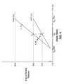
- FIG. 5shows a battery regeneration control graph and how the gasoline engine torque speed trajectory changes and allows the main battery charge to increase or the depth of discharge (DOD) to decrease.
- the charge in the batteryincreases as operation moves to the right in the graph.
- FIG. 6shows how the engine “turn on” speed cycles and allows the DOD to cycle about a given state depending on the driving conditions.
- the premiseis that each "average” operating speed has a “turn on” speed which will maintain the charge. If so, then we can regulate the battery state of charge (SOC) by "turn on” speed depending on the slope A"A, A"B, or A"C. The regulation fidelity is best with A"C. Additional information can be found in my prior U.S. Patent No. 5,842,534 and U.S. Patent No. 6,116,363 .
- the second objective of this inventionis to provide a technique for operating the vehicle while simultaneously maintaining or increasing the battery state of charge.
- the regeneration periodshould occur over a relatively long period of time or at a low current so that the recharge losses are minimized.
- the engineis to be kept operating at the IOL but the vehicle maximum performance may be reduced slightly.
- the charge rateshould be low.
- the battery regeneration power levelis chosen so that it approximately matches the average power of the vehicle while driving. If this power setting is low relative to the average load, the batteries will slowly discharge. If the setting is high relative to the average then the state of charge will gradually creep up.
- the objectiveis to set the charge level so that the average state of charge creeps up and down at a low frequency relative to the drivers' action.
- the frequency of cyclingshould be less than 1/10 th the frequency of the driver action at the accelerator pedal.
- the cycling frequencymay be related to the battery pack size and other system parameters. The larger the battery pack, the lower this charge frequency response may be and the more robust the control system.
- the bandwidth of energy managementshould be approximately 1 /10 th the driver's bandwidth.
- the driver's bandwidthshould be approximately 1/10 th the bandwidth of the internal component controllers, such as the pressure controllers of the CVT and the engine throttle controller. This separation of operating frequencies allows the vehicle to achieve robust control. Prediction or "fuzzy" concepts may be required for smaller battery packs. These control frequency ranges may overlap, thus making prediction necessary. Boundaries of these control ranges can always be reached by excessive use of the system in some way that is out of the ordinary. The important feature is that these boundaries are seldom reached and when they are reached the driver knows what alternative action is needed to correct the deficiency.
- the drivermay simply go easier on the accelerator pedal or the computer may set the recharge level slightly higher, meaning the battery regeneration power level in FIG. 5 is set higher.
- Such actionmay be taken by a computer or manually by the driver which makes the system under manual control but such manual control is not necessary in general and once the level of charge is set for a particular driver it may not have to be adjusted again.
- This level of battery maintenancemay be related to the way a person drives. The vehicle can be set to the average driver and the driver could tune above or below this setting. The car would not be put into jeopardy in any way by this control. Only system efficiency is affected.
- the gasoline engineis set to operate at a power level higher than required to maintain vehicle speed. If the cycle described under normal level road conditions as described above starts at point A in FIG. 2 , then due to battery direct charge command, the engine operating point is moved to point AC to the right along the IOL. Thus, at steady state cruise point AC supplies the road load and charge load "X". If the accelerator pedal moves suddenly to accelerate the car, then the operating point moves to BC. The incremental power is the same as in FIG. 2 . Thus the vehicle acceleration is not affected under normal operation. The battery charge curve simply moves to the right to the points AC, BC, CC, and DC. The points E, F remain the same. As the level of negative power reaches A' the engine throttle is opened to operate on the IOL and the EMG is set to charge the batteries at the level at the start of this example cycle.
- the amount of "charge power” required to maintain battery state of chargeis determined by the amount of deficit from the ideal set by a system control policy.
- the "gain” on charge power deficitwill determine the time constant of the charge. This charge policy is not normally needed since the charge depletion policy of U.S. Patent No. 5,842,534 accounts for most of the transition from charge depletion to charge sustaining.
- FIG. 6herein shows an improved control policy which allows the vehicle to use more gasoline and less electric energy on a given driving cycle, as the DOD increases, until points A, B or C.
- the engine, motor, CVT, and computer controllerwould control the engine "turn-on" speed and DOD control line to maintain a DOD set in the computer.
- DOD 6indicate three example DOD's that can be maintained with this policy in a particular low speed driving cycle.
- This policyshould regulate a "turn-on" velocity for a consistent driving cycle.
- the systemwill deplete the battery to DOD 1, 2, or 3 corresponding to "turn on” policies A, B, or C, respectively.
- the "turn-on” speedcan be lowered to V MIN and observe the DOD. If the DOD decreases to A', B' and C' respectively, then the battery charges. At this point the control computer can switch the "turn-on” speeds to A", B" and C" respectively.
- the DODwill then cycle between 1 & 1' or 2 & 2' or 3 & 3'.
- the computer control concept of FIG. 5would be used to increase the engine power operating point by increasing the engine speed, while operating the engine along the IOL, as described in the second paragraph of this Section 2 above.
- the control computerwill determine the amount of charge power dependent on DOD error, charge rate and a control loop frequency determined by driving characteristics. It is desired to maintain the DOD at a relatively low frequency compared to the driver accelerator pedal frequency.
- the block diagram of FIG. 7depicts a general implementation for the policies discussed above.
- the policiesare set by factors 100 such as battery life, electric energy use, and other long term factors or policies and, if desired, an optional manual control (e.g., override switch) 102 can be provided.
- the desired depth of discharge 104is then compared with the current average depth of discharge 106 and an error signal 108 is output to the powertrain controller (e.g., engine, motor, CVT or multispeed transmission control computers) 110.
- the output of powertrain controller 110is the engine "turn on" speed or charge power setting 112 which is input to the powertrain system (e.g., engine, motor, CVT or multispeed transmission) 114 along with fuel 116.
- the electrical energy use 118is monitored by the battery status computer 120 where the battery depth of discharge 122 is determined in real time.
- the real-time depth of discharge measurementsare time averaged in an averaging program 124 to generate the current average DOD 106.
- a mountain drive modee.g., low gear selection such as D1 or D2 in a transmission
- the present inventionprovides a number of advantages over other control methods, including, but not limited to:
- control methods, policies and/or algorithms of the present inventionmay be implemented on any conventional computer system under processor control using conventional programming techniques.
Landscapes
- Engineering & Computer Science (AREA)
- Chemical & Material Sciences (AREA)
- Combustion & Propulsion (AREA)
- Transportation (AREA)
- Mechanical Engineering (AREA)
- Automation & Control Theory (AREA)
- Power Engineering (AREA)
- Electric Propulsion And Braking For Vehicles (AREA)
- Hybrid Electric Vehicles (AREA)
- Control Of Vehicle Engines Or Engines For Specific Uses (AREA)
- Crystals, And After-Treatments Of Crystals (AREA)
Abstract
Description
- This application claims priority from
U.S. provisional application serial number 60/259,662 filed on January 3, 2001 U.S. application serial number 09/677,288 filed on October 2, 2000 PCT/US99/09880 U.S. application serial number 09/063,993 filed on April 21, 1998 , nowU.S. Patent No. 6,054,844 . This application is also a continuation-in-part ofU.S. application serial number 09/063,995 filed on April 21, 1998 , nowU.S. Patent No. 6,116,363 . Priority is claimed to each of the foregoing applications. - The present invention generally pertains to an improved method for controlling the operating characteristics of an internal combustion engine coupled to a drive train having a continuously variable transmission or a properly spaced multi-speed transmission, and more particularly to a partial charge depletion and charge sustaining control method suitable for use with smaller battery packs.
- In
U.S. Patent No. 5,842,534 , I described a charge depletion method and apparatus for operating the electric motor and small auxiliary power unit, such as an internal combustion engine, in a hybrid electric vehicle (HEV) separately or together depending upon the driving conditions. Operation of the electric motor and auxiliary power unit are coordinated so that the vehicle operates as zero emissions vehicle (ZEV) or electric car at all speeds below a cruising threshold, unless the depth of discharge of the batteries exceeds a charge threshold in which case the vehicle operates in an HEV mode. Further, the vehicle operates in an HEV mode at speeds above the cruising threshold. The batteries are depleted during operation and are not charged by the auxiliary power unit, except during emergencies in which case the batteries are only charged enough to provide a performance enhancement to the small auxiliary power unit. In operation, the vehicle speed is sensed, the level of the depth of discharge of the battery is sensed, at vehicle speeds above a threshold speed the auxiliary power unit is activated to power the vehicle and the electric motor is used to supplement the auxiliary power unit when required, at vehicle speeds below the threshold speed the auxiliary power unit is deactivated and the electric motor is used to power the vehicle, and the threshold speed is automatically and dynamically adjusted as a function of said level of the depth of discharge. - In
U.S. Patent No. 6,116,363 , I described another charge depletion method and apparatus where operation of the electric motor and auxiliary power unit are coordinated as a function of a control policy for the auxiliary power unit based on desired least fuel consumption and/or vehicle emissions characteristics. In operation, the speed of the vehicle is sensed, the depth of discharge of the battery is sensed, at vehicle speeds above a threshold speed auxiliary power unit is activated to power the vehicle and the electric motor is used to supplement the auxiliary power unit when required, at vehicle speeds below the threshold speed the auxiliary power unit is deactivated and the electric motor is used to power the vehicle, and the threshold speed is dynamically adjusted as a function of the depth of discharge, wherein the threshold speed and adjustment of the threshold speed are a function of a control policy for the auxiliary power unit based on desired fuel consumption and/or vehicle emissions characteristics. - In my prior
U.S. application serial number 09/677,288 filed on October 2, 2000 PCT/US99/09880 published on May 4, 2000 WO 00/25417 U.S. No. 6,054,844 , which describes a method and apparatus for controlling the power output of an internal combustion engine in a vehicle having a continuously variable transmission (CVT) or automatic transmission (AT). In these methods, a motor/generator is controlled to counteract the negative effect of the-R̊IESE term in the dynamic equation

U.S. No. 5,842,534 , where the large battery pack is charged from stationary powerplants. With smaller battery packs, however, the efficiency of energy into and out of the battery is lower. Therefore, there is a need for a control method that is particularly suited for use with smaller batter packs. - German Patent
DE 195 05 431 A1 , which represents the closest prior art according to the preamble ofapparatus Claim 1 andmethod claim 3, discloses an achievement control system for motor vehicles with a majority of achievement-converting components as well as with means for the determination of the efficiency of the individual components means are for the determination of the overall efficiency from the efficiencies of the individual components as well as means for the computation and attitude of a value for an efficiency-affecting parameter of a component to reaching an optimal overall efficiency. Preferably efficiency-affecting parameters, whose values are adjustable for reaching an optimal overall efficiency, are the achievement and/or one the achievement proportional size, which is to be delivered from an achievement-producing component, and/or which number of revolutions and/or one the number of revolutions of a component proportional size. - United States Patent
US-A-5,469,816 discloses a control mechanism for an electric generator motor which can prevent excessive charging and insufficient capacity of an electrical power storage device includes a controller controlling operation of the electric generator motor when a total of restorable electrical power calculated on the basis of vehicle state and a present capacity of the electrical storage device is smaller than a specified reference capacity. The control mechanism effects a motor operation, i.e., application of torque, of the generator motor within a range in which the capacity of the electrical storage device does not fall below a specified minimum charge level required for driving vehicle auxiliary devices. The control mechanism effects motor operation of the electric generator motor with continuously changing restorable electrical power which has a positive correlation with an effective amount of depression of a brake pedal. The control device effects application of torque using the motor generator when a total of restorable electrical power is larger than a specified minimum capacity value. - European Patent
EP-A-1,008,484 discloses a control system for a hybrid vehicle with an engine and a motor, and in particular, to a control system for a hybrid vehicle which can balance the charging and discharging of a battery even when the battery discharges much energy. - United. States Patent
US-A-6,054,844 discloses a method and apparatus for controlling the power output of an internal combustion engine in a vehicle, wherein a motor/generator or a generator/motor is coupled to the output shaft of the engine and the positive and negative torque of the motor/generator or the generator/motor is varied to control the power output of the engine as a function of speed for all manners of performance of the vehicle. The engine operates along a predetermined ideal operating line at all speeds of the vehicle. - Further regarding German Patent
DE 195 05 431 A1 : that patent discloses a control strategy that observes the instantaneous state of charge Q of the battery and calculates the overall efficiency of the power converting components before selecting a power setting a power setting of the internal combustion engine. However, because the control strategy inDE 195 05 431 A1 looks a the instantaneous state of charge Q, frequent driver input (such as found with city driving, having frequent stopping, accelerating, and shifting) can result in frequent charging and discharging of the battery. - The present invention provides the needed control method for operating internal combustion engine electric hybrid vehicles with smaller battery packs, particularly in configurations where an electric motor (E/M) or electric motor/generator (E/MG), a battery, and associated controls are inserted between the engine and a continuously variable or automatic transmission.
- According to an aspect of the invention, the interaction between the combustion engine and battery operated electric motor is controlled by taking energy into the batteries only if it is more fuel efficient than throttling the engine and operating the engine at a lower efficiency.
- According to another aspect of the invention, the batteries are charged to a certain state or the batteries are maintained at a particular state of charge.
- According to still another aspect of the invention, the engine "turn-on" speed is used to regulate the depth of discharge of the battery system by observing the average depth of discharge over a period of time and maintaining the depth of discharge between a maximum and minimum with the engine.
- According to a further aspect of the invention, the depth of discharge of the battery system is cycled with the engine to maintain the depth of discharge between a maximum and minimum.
- Furthermore, in accordance with another aspect of the invention, the average depth of discharge is maintained over a period of time that is long compared to driver action.
- An aspect of the invention also includes a battery control method wherein a closed loop system is set to regulate depth of discharge of the battery with a frequency bandwidth sufficient to meet predetermined operating criteria such as battery life, vehicle range, and driveability.
- An additional aspect of the invention is to regulate the depth of discharge of the battery system in a mechanical CVT hybrid electric vehicle without fully charging the battery with the engine.
- Another aspect of the invention is to use vehicle speed as a determinant of vehicle energy demand.
- Still another aspect of the invention is to provide a vehicle control system for a CVT engine-motor parallel prime mover, by using the electric motor and battery to provide acceleration and deceleration compensation for the CVT powertrain system dynamics. This provides higher level instant response and better fuel economy than can be achieved with an internal combustion CVT alone.
- A further aspect of the invention is to optimize overall powertrain efficiency, by considering circulated energy through the E/M battery system by comparing engine throttle vs. E/M control for deceleration.
- Further aspects and advantages of the invention will be brought out in the following portions of the specification, wherein the detailed description is for the purpose of fully disclosing preferred embodiments of the invention without placing limitations thereon.
- The invention will be more fully understood by reference to the following drawings which are for illustrative purposes only:
FIG. 1 is a block diagram of an engine, electric motor generator, CVT, battery and computer-controlled parallel hybrid powertrain configuration according to the present invention.FIG. 2 is a graph of a typical acceleration/deceleration cycle in the HEV mode where battery status to be controlled with the accelerator pedal showing combined engine and electric motor torque - speed characteristics and engine efficiency in accordance with the present invention.FIG. 3 is a graph showing engine throttle - torque - speed curves in relation to the ideal operating line (IOL) in accordance with the present invention for the 100% IOL line, the 65% IOL line, and the 0% IOL.FIG. 4 is a graph of throttle-speed curves showing a throttle schedule during an acceleration-deceleration cycle according to the present invention derived from the curves shown inFIG. 3 .FIG. 5 is a battery regeneration control graph depicting incremental battery depth of discharge maintenance according to the present invention.FIG. 6 is a graph depicting an alternative charge maintenance control by a charge depletion control system showing how the engine "turn on" speed cycles and allows the DOD to cycle about a given state depending on the driving conditions.FIG. 7 is a control diagram for battery charge maintenance by control of an engine, E/MG, and CVT or multispeed transmission according to the present invention.- Referring now to
FIG. 1 through FIG. 7 , the present invention comprises a control method and system for operating internal combustion engine electric hybrid vehicles with smaller battery packs, particularly in configurations where an electric motor (E/M) or electric motor/generator (E/MG), a battery, and associated controls are inserted between the engine and a continuously variable or automatic transmission. It will be appreciated that when the term "battery" is used herein, the term can include any energy storage device such as an ultra-capacitor, electrochemical battery, or the like. - A first objective of this invention is to minimize the fuel consumption and emissions for a parallel hybrid electric powertrain given an engine, an electric motor/generator, a continuously variable transmission (CVT) or properly spaced multi-speed automatic transmission, a powertrain system computer controller, and a specific battery pack. Each of these components have losses when operating. This invention minimizes the sum of the losses of the components to provide the best conversion efficiency from liquid fuel to drive energy at the wheels. A second objective is to provide the best efficiency for recharging or maintaining the charge of the battery pack. The theory of operation is described in the following texts and figures.
FIG. 1 shows a block diagram of an embodiment of a parallel hybridelectric CVT system 10 designed for low fuel consumption and emissions, and high performance according to the present invention. This figure shows aninternal combustion engine 12 powered by afuel supply 14, and an electric motor generator (E/MG) 16 coupled to theengine 12 either via a clutch 18 or other coupling device such as a torque converter, etc. E/MG 16 is powered by abattery 20, and the battery energy is controlled via an E/MG controller 22, which controls the torque onengine 12 applied by E/MG 16. E/MG 16 is coupled to a CVT ormultispeed transmission 24 which receives, at its input, a combination of the engine torque (TE) and motor torque (TM) 26 and in turns adrive shaft 28. Driveshaft 28 is in turn coupled to afinal drive 30 which turns anaxle 32 which is coupled to thewheels 34. Acontrol computer 36 sets the control parameters and monitors the operation of the system. The control parameters include, for example, example, theengine throttle 38, shift of ratio rate (rate of change of ratio) 40 of the CVT ormultispeed transmission 24, and E/MG torque parameters 42 forcontroller 22. Operational characteristics that are monitored include theratio 44 of the CVT ormultispeed transmission 24, engine speed (SE) 46, depth ofdischarge 48 of the battery provided by a battery monitoring system (computer) 50,vehicle speed 52, and driver input 54 (e.g., accelerator/brake pedal motion). Engine torque (TE) 56 to the extent required is not measured directly but is derived from the ideal operation line (IOL).FIG. 2 shows a typical acceleration/deceleration cycle with the accelerator pedal. Positive (+) torque (+TM) means the E/MG is taking energy from the batteries, and negative (-) torque (-TM) means the E/MG is acting as a generator to recharge or regenerate the batteries. The cycle begins with the vehicle operating at a steady state on a level road with the accelerator pedal in a particular position. The driver suddenly decides that he needs-to accelerate the vehicle. The-accelerator pedal in this powertrain system commands "power," and as it is suddenly moved to a new operating position, torque from the electric motor will be increased to reach the required power instantly. Then power is held according to the accelerator pedal command and the CVT ratio is changed to increase the gasoline engine power by changing its speed and throttle position so that it remains on the ideal operating line (IOL). The electric motor (E/MG) torque is decreased keeping a constant total power curve until the E/MG torque reaches zero. A new higher power is reached along the ideal operating line (IOL) of the engine. The energy required to do this must originate from the batteries and is supplied by the electric motor. Thus, starting from operating point "A" the engine and E/MG will move to point "B" instantly supplying more torque and power. The E/MG torque decreases along a constant power line BC as the ratio of the CVT is changed until a new operating point C is reached. This power level and operating point of the engine will be maintained as long as the accelerator pedal is held in a fixed position. The CVT will change ratio as the vehicle accelerates. When the driver decides to return the accelerator pedal to the power level corresponding to point "A" (where the cycle started) the electric motor generator will provide a negative torque to lower the power level at "C" to the power level of line AD almost instantly. Then this negative E/MG torque will cause the engine speed to decrease along the IOL to point "E". Since the load (torque) on the engine is high and the throttle is not closed, the engine continues to operate at high efficiency and low emissions. The E/MG is used to "drag" the engine speed down and consequently the power down to "E". The power generated then returns to the batteries up to point E, the electric motor torque is decreased to zero, and the engine throttle is decreased to the power level of the curve from "D" to "A". This level of power is indicated by point "F". The points "E" and "F" are chosen by a computation of efficiencies where there is equal or higher efficiency by engine throttle than by regeneration through the battery electric motor system. (The electric motor generator and battery system efficiency may be about (.9G x.9B x.9BX x .9M) = 0.65). Thus, point "E" is determined by when the brake specific fuel consumption (BSFC) of the engine is increased more than 35% to achieve the power reduction desired at point "F". At this point, the E/MG torque is set to zero and the throttle of the engine is reduced to satisfy the power command.FIG. 3 shows the engine throttle curves in relation to the ideal operating line (IOL). Shown on this figure are the 100% IOL line, the 65% IOL line, and the 0% IOL line. These lines then determine the engine efficiency relative to the IOL. Thus the 65% IOL line is about 65% as efficient (or 35% higher BSFC) as the 100% IOL operating line. Deceleration torque "E" to "F" can be accomplished by a throttle change from 30% to 18% or by regenerated energy to the battery. Regeneration has a loss of energy due to a generator-battery-motor loss of approximately 35%.- The throttle/speed curves of
FIG. 4 are derived from the curves inFIG. 3 .FIG. 4 shows the engine throttle as the accelerator pedal was increased from power "A" to "B-C" and returned to "A" going through point "E" on the IOL. The engine throttle is reduced to approximately the 65% IOL line at this instant to point "F". This point "E" is where the loss of engine efficiency due to throttling is less than the losses through the electrical system. The power from point "F" to "A" is held constant with engine throttle modulation until "A" is reached again. The electric motor generator torque is set to zero from "F" to "A." FIG. 5 shows a battery regeneration control graph and how the gasoline engine torque speed trajectory changes and allows the main battery charge to increase or the depth of discharge (DOD) to decrease. The charge in the battery increases as operation moves to the right in the graph.FIG. 6 shows how the engine "turn on" speed cycles and allows the DOD to cycle about a given state depending on the driving conditions. The premise is that each "average" operating speed has a "turn on" speed which will maintain the charge. If so, then we can regulate the battery state of charge (SOC) by "turn on" speed depending on the slope A"A, A"B, or A"C. The regulation fidelity is best with A"C. Additional information can be found in my priorU.S. Patent No. 5,842,534 andU.S. Patent No. 6,116,363 .- The second objective of this invention is to provide a technique for operating the vehicle while simultaneously maintaining or increasing the battery state of charge.
- Referring again to
FIG. 5 , a technique to regenerate the batteries with the liquid fuel engine if needed is shown. The regeneration period should occur over a relatively long period of time or at a low current so that the recharge losses are minimized. The engine is to be kept operating at the IOL but the vehicle maximum performance may be reduced slightly. The charge rate should be low. The battery regeneration power level is chosen so that it approximately matches the average power of the vehicle while driving. If this power setting is low relative to the average load, the batteries will slowly discharge. If the setting is high relative to the average then the state of charge will gradually creep up. The objective is to set the charge level so that the average state of charge creeps up and down at a low frequency relative to the drivers' action. The frequency of cycling should be less than 1/10th the frequency of the driver action at the accelerator pedal. The cycling frequency may be related to the battery pack size and other system parameters. The larger the battery pack, the lower this charge frequency response may be and the more robust the control system. Or, the bandwidth of energy management should be approximately 1 /10th the driver's bandwidth. The driver's bandwidth should be approximately 1/10th the bandwidth of the internal component controllers, such as the pressure controllers of the CVT and the engine throttle controller. This separation of operating frequencies allows the vehicle to achieve robust control. Prediction or "fuzzy" concepts may be required for smaller battery packs. These control frequency ranges may overlap, thus making prediction necessary. Boundaries of these control ranges can always be reached by excessive use of the system in some way that is out of the ordinary. The important feature is that these boundaries are seldom reached and when they are reached the driver knows what alternative action is needed to correct the deficiency. - For example, if the batteries are being discharged and the regeneration level is too low, the driver may simply go easier on the accelerator pedal or the computer may set the recharge level slightly higher, meaning the battery regeneration power level in
FIG. 5 is set higher. Such action may be taken by a computer or manually by the driver which makes the system under manual control but such manual control is not necessary in general and once the level of charge is set for a particular driver it may not have to be adjusted again. This level of battery maintenance may be related to the way a person drives. The vehicle can be set to the average driver and the driver could tune above or below this setting. The car would not be put into jeopardy in any way by this control. Only system efficiency is affected. - Where the power to regenerate the batteries is determined by the control computer to be "X" kilowatts, the gasoline engine is set to operate at a power level higher than required to maintain vehicle speed. If the cycle described under normal level road conditions as described above starts at point A in
FIG. 2 , then due to battery direct charge command, the engine operating point is moved to point AC to the right along the IOL. Thus, at steady state cruise point AC supplies the road load and charge load "X". If the accelerator pedal moves suddenly to accelerate the car, then the operating point moves to BC. The incremental power is the same as inFIG. 2 . Thus the vehicle acceleration is not affected under normal operation. The battery charge curve simply moves to the right to the points AC, BC, CC, and DC. The points E, F remain the same. As the level of negative power reaches A' the engine throttle is opened to operate on the IOL and the EMG is set to charge the batteries at the level at the start of this example cycle. - When the brake pedal is depressed, the braking policy described in my International Publication No.
WO 00/25417 U.S. No. 5,842,534 ,U.S. No. 6,054,844 , andU.S. No. 6,116,363 is invoked as before. - The amount of "charge power" required to maintain battery state of charge is determined by the amount of deficit from the ideal set by a system control policy. The "gain" on charge power deficit will determine the time constant of the charge. This charge policy is not normally needed since the charge depletion policy of
U.S. Patent No. 5,842,534 accounts for most of the transition from charge depletion to charge sustaining. - Note that the normal "charge depletion" algorithm of
U.S. Patent No. 5,842,534 , depletes charge by control of engine "turn on" speed shown as shown inFIG. 4 of that patent. If this speed is high (e.g., "highway" driving) the battery depletes as the vehicle drives. For "city" driving, however,FIG. 6 herein shows an improved control policy which allows the vehicle to use more gasoline and less electric energy on a given driving cycle, as the DOD increases, until points A, B or C. Here, the engine, motor, CVT, and computer controller would control the engine "turn-on" speed and DOD control line to maintain a DOD set in the computer. The control lines A, B, and C inFIG. 6 indicate three example DOD's that can be maintained with this policy in a particular low speed driving cycle. This policy should regulate a "turn-on" velocity for a consistent driving cycle. The system will deplete the battery toDOD - During highway cruise, at high velocities above V MAX, there may not be enough deceleration events with enough energy to maintain a certain DOD. Then the computer control concept of
FIG. 5 would be used to increase the engine power operating point by increasing the engine speed, while operating the engine along the IOL, as described in the second paragraph of thisSection 2 above. The control computer will determine the amount of charge power dependent on DOD error, charge rate and a control loop frequency determined by driving characteristics. It is desired to maintain the DOD at a relatively low frequency compared to the driver accelerator pedal frequency. - The block diagram of
FIG. 7 depicts a general implementation for the policies discussed above. The policies are set byfactors 100 such as battery life, electric energy use, and other long term factors or policies and, if desired, an optional manual control (e.g., override switch) 102 can be provided. The desired depth ofdischarge 104 is then compared with the current average depth ofdischarge 106 and anerror signal 108 is output to the powertrain controller (e.g., engine, motor, CVT or multispeed transmission control computers) 110. The output ofpowertrain controller 110 is the engine "turn on" speed or charge power setting 112 which is input to the powertrain system (e.g., engine, motor, CVT or multispeed transmission) 114 along withfuel 116. Theelectrical energy use 118 is monitored by thebattery status computer 120 where the battery depth ofdischarge 122 is determined in real time. The real-time depth of discharge measurements are time averaged in anaveraging program 124 to generate the currentaverage DOD 106. - At low to zero accelerator pedal depression, it is preferably to use the CVT or transmission to control the engine to operate at its minimum speed. This minimum speed is maintained at closed throttle and fuel shut off. The negative power at this minimum engine speed is low and provides a natural source of deceleration for a "normal" driveability feeling. Further, since the negative power is low, for good driveability the engine clutch may not be opened. The engine clutch opening would occur at low vehicle speeds set by other policies discussed above.
- For long mountain grade deceleration where this battery system can no longer accept charge, a mountain drive mode (e.g., low gear selection such as D1 or D2 in a transmission), may be desired. This is easily accomplished by setting the minimum engine speed higher, thereby providing high or engine deceleration power and closed throttle and zero fuel.
- Accordingly, the present invention provides a number of advantages over other control methods, including, but not limited to:
- 1. Regulating the DOD of the battery system by the use of engine "turn-on" speed for low speed city driving;
- 2. Regulating the DOD of the battery system by averaging the DOD over a long period, long compared with driver action;
- 3. Setting a closed loop system to regulate DOD of a hybrid electric vehicle with a frequency bandwidth low enough to maximize battery life, range, etc.;
- 4. Depleting the batteries to provide direct "wall-plug" electric vehicle propulsion energy, but not recharging with gasoline to full charge. The engine is used to maintain a level of DOD which is sufficient to anticipate all expected energy requirements within a driving cycle; and
- 5. Using vehicle speed as a determinant of driving energy demand. For example, 60 mph and above is considered highway driving. Below 60 mph is considered city driving. Thus the proposed control policy is changed according to vehicle speed. It is understood that other control details such as driving histories, time in a driving state, and other factors may be used to practically implement these controls.
- Furthermore, those skilled in the art will readily appreciate that the control methods, policies and/or algorithms of the present invention may be implemented on any conventional computer system under processor control using conventional programming techniques.
- Although the description above contains many specificities, these should not be construed as limiting the scope of the invention but as merely providing illustrations of some of the presently preferred embodiments of this invention. Therefore, it will be appreciated that the scope of the present invention fully encompasses other embodiments which may become obvious to those skilled in the art, and that the scope of the present invention is accordingly to be limited by nothing other than the appended claims, in which reference to an element in the singular is not intended to mean "one and only one" unless explicitly so stated, but rather "one or more." Moreover, it is not necessary for a device or method to address each and every problem sought to be solved by the present invention, for it to be encompassed by the present claims. Furthermore, no element, component, or method step in the present disclosure is intended to be dedicated to the public regardless of whether the element, component, or method step is explicitly recited in the claims.


Claims (13)
- A control apparatus for a hybrid electric vehicle having an internal combustion engine (12), an electric motor (16), and a battery system (20) for powering the electric motor (16), comprising:means for controlling the interaction between the internal combustion engine (12), and electric motor (16) to regenerate energy into the battery system (20)characterized in that said means for controlling uses a function of the average depth of discharge of the battery system (20) over a period of time.
- A control apparatus as recited in Claim 1, further comprising:charging the battery system (20) to a desired state of charge during operation of the vehicle, where the desired state of charge is a function of average vehicle speed or average vehicle power.
- A method for controlling the interaction between an internal combustion engine (12) and electric motor (16) operated by a battery system (20) in a hybrid electric vehicle,characterized in that it comprises:averaging the depth of discharge of the battery system (20) over time and regenerating energy into the battery system (20) only if engine fuel efficiency during regeneration and during subsequent power production from the electric motor (16) is greater than engine fuel efficiency resulting from throttling engine power.
- A method as recited in Claim 3, further comprising:charging the battery system (20) to a desired state of charge during operation of the vehicle, where the desired state of charge is a function of average vehicle speed or average vehicle power.
- A control apparatus as recited in Claim 2, further comprising:applying an engine "turn-on" signal derived from vehicle speed to regulate depth of discharge of the battery system (20) by observing average depth of discharge of the battery system (20) over a period of time compared to the desired state of charge.
- A control apparatus as recited in Claim 1, further comprising:a closed loop system to regulate depth discharge of the battery system (20) with a cycling frequency determined by the frequency of driver action.
- A control apparatus as recited in Claim 6., further comprising:regulating depth of discharge of the battery system without fully charging the battery system (20) with the engine (12).
- A method as recited in Claim 3, further comprising:setting a closed loop system to regulate depth discharge of the battery system (20) with a cycling frequency determined by the frequency of driver action.
- A method as recited in Claim 8, further comprising:regulating depth of discharge of the battery system (20) without fully charging the battery system (20) with the engine (12).
- A control apparatus as recited in Claim 1, further comprising:means for setting a desired depth of discharge of the battery system (20) as a function of average vehicle power or average vehicle speed where a desired cycling frequency for recharging and discharging the battery system (20) as a function of driver action frequency is calculated and the internal combustion engine (12) is controlled within the desired cycling frequency to maintain the desired depth of discharge of the battery system (20).
- A method as recited in Claim 3, further comprising:selecting a desired depth of discharge of the battery system (20) as a function of average vehicle power or average vehicle speed, selecting a desired cycling frequency for recharging and discharging the battery system (20)as a function of driver input frequency, and controlling the internal combustion engine (12) within the desired cycling frequency to maintain the desired depth of discharge of the battery system (20).
- A control apparatus as recited in Claim 1, further comprising:a continuously variable transmission (CVT) powertrain system (24) connected to the electric motor (16) where the means for controlling uses average vehicle speed or average vehicle power to select a desired depth of discharge rate for the battery system (20) and uses the electric motor (16) and battery system (20) to provide acceleration and deceleration compensation for the CVT powertrain system (24) dynamics.
- A method as recited in Claim 3, further comprising:connecting a continuously variable transmission (CVT) powertrain to the electric motor (16) and using the electric motor (16) and battery system (20) to provide acceleration and deceleration compensation for the CVT powertrain system (24) dynamics.
Applications Claiming Priority (3)
| Application Number | Priority Date | Filing Date | Title |
|---|---|---|---|
| US25966201P | 2001-01-03 | 2001-01-03 | |
| US259662P | 2001-01-03 | ||
| PCT/US2002/000220WO2002058209A1 (en) | 2001-01-03 | 2002-01-03 | Method for controlling the operating characteristics of a hybrid electric vehicle |
Publications (3)
| Publication Number | Publication Date |
|---|---|
| EP1354389A1 EP1354389A1 (en) | 2003-10-22 |
| EP1354389A4 EP1354389A4 (en) | 2005-07-20 |
| EP1354389B1true EP1354389B1 (en) | 2010-06-30 |
Family
ID=22985846
Family Applications (1)
| Application Number | Title | Priority Date | Filing Date |
|---|---|---|---|
| EP02718789AExpired - LifetimeEP1354389B1 (en) | 2001-01-03 | 2002-01-03 | Method for controlling the operating characteristics of a hybrid electric vehicle |
Country Status (9)
| Country | Link |
|---|---|
| US (1) | US20090044996A1 (en) |
| EP (1) | EP1354389B1 (en) |
| JP (1) | JP2004527193A (en) |
| KR (1) | KR100916987B1 (en) |
| CN (1) | CN100362722C (en) |
| AT (1) | ATE472841T1 (en) |
| CA (1) | CA2433420A1 (en) |
| DE (1) | DE60236844D1 (en) |
| WO (1) | WO2002058209A1 (en) |
Cited By (2)
| Publication number | Priority date | Publication date | Assignee | Title |
|---|---|---|---|---|
| US8467927B2 (en) | 2011-11-03 | 2013-06-18 | Ford Global Technologies, Llc | Method and system for speed control of a hybrid vehicle |
| US8467926B2 (en) | 2011-11-03 | 2013-06-18 | Ford Global Technologies, Llc | Method and system for valve operation control |
Families Citing this family (75)
| Publication number | Priority date | Publication date | Assignee | Title |
|---|---|---|---|---|
| US7011600B2 (en) | 2003-02-28 | 2006-03-14 | Fallbrook Technologies Inc. | Continuously variable transmission |
| CN1298560C (en)* | 2003-12-30 | 2007-02-07 | 联合汽车电子有限公司 | Mixed power automobile control system and its control method |
| WO2006041718A2 (en) | 2004-10-05 | 2006-04-20 | Fallbrook Technologies, Inc. | Continuously variable transmission |
| CN103121399B (en)* | 2004-11-12 | 2016-05-11 | 杨泰和 | Separate series-parallel hybrid dual power drive system |
| JP4396515B2 (en)* | 2004-12-22 | 2010-01-13 | トヨタ自動車株式会社 | Power supply |
| WO2007070167A2 (en) | 2005-10-28 | 2007-06-21 | Fallbrook Technologies Inc. | Electromotive drives |
| PL1954959T3 (en) | 2005-11-22 | 2013-10-31 | Fallbrook Ip Co Llc | Continuously variable transmission |
| CN102221073B (en) | 2005-12-09 | 2013-03-27 | 福博科技术公司 | Continuously variable transmission |
| EP1811202A1 (en) | 2005-12-30 | 2007-07-25 | Fallbrook Technologies, Inc. | A continuously variable gear transmission |
| CA2650224C (en) | 2006-05-09 | 2014-02-25 | Azure Dynamics Inc. | Process and apparatus for reducing nitrogen oxide emissions in genset systems |
| US8346416B2 (en) | 2006-06-26 | 2013-01-01 | Azure Dynamics, Inc. | Method, apparatus, signals and media, for selecting operating conditions of a genset |
| CN102269055B (en) | 2006-06-26 | 2013-08-28 | 福博科技术公司 | Continuously variable transmission |
| US7826939B2 (en) | 2006-09-01 | 2010-11-02 | Azure Dynamics, Inc. | Method, apparatus, signals, and medium for managing power in a hybrid vehicle |
| CN101200170B (en)* | 2006-12-11 | 2010-06-16 | 比亚迪股份有限公司 | Acceleration device and method for electric vehicle accelerator |
| EP2125469A2 (en) | 2007-02-01 | 2009-12-02 | Fallbrook Technologies Inc. | System and methods for control of transmission and/or prime mover |
| US20100093479A1 (en) | 2007-02-12 | 2010-04-15 | Fallbrook Technologies Inc. | Continuously variable transmissions and methods therefor |
| TWI461615B (en) | 2007-02-16 | 2014-11-21 | Fallbrook Ip Co Llc | Infinitely variable transmissions, continuously variable transmissions, methods, assemblies, subassemblies, and components therefor |
| JP4379484B2 (en)* | 2007-04-06 | 2009-12-09 | 株式会社デンソー | Vehicle system |
| EP2142826B1 (en) | 2007-04-24 | 2015-10-28 | Fallbrook Intellectual Property Company LLC | Electric traction drives |
| US8641577B2 (en) | 2007-06-11 | 2014-02-04 | Fallbrook Intellectual Property Company Llc | Continuously variable transmission |
| CN103697120B (en) | 2007-07-05 | 2017-04-12 | 福博科技术公司 | Continuously variable transmission |
| US8098041B2 (en)* | 2007-11-04 | 2012-01-17 | GM Global Technology Operations LLC | Method of charging a powertrain |
| CN103939602B (en) | 2007-11-16 | 2016-12-07 | 福博科知识产权有限责任公司 | Controllers for variable speed drives |
| US8020652B2 (en)* | 2007-12-04 | 2011-09-20 | Ford Global Technologies, Llc | Generator power-based cold start strategy |
| US8321097B2 (en) | 2007-12-21 | 2012-11-27 | Fallbrook Intellectual Property Company Llc | Automatic transmissions and methods therefor |
| US8313405B2 (en) | 2008-02-29 | 2012-11-20 | Fallbrook Intellectual Property Company Llc | Continuously and/or infinitely variable transmissions and methods therefor |
| US7904217B2 (en)* | 2008-03-25 | 2011-03-08 | International Truck Intellectual Property Company, Llc | Battery pack management strategy in a hybrid electric motor vehicle |
| US8000865B2 (en)* | 2008-05-06 | 2011-08-16 | GM Global Technology Operations LLC | Method and apparatus for transitioning an electrically variable transmission |
| CN102112778B (en) | 2008-06-06 | 2013-10-16 | 福博科技术公司 | Infinitely variable transmission, continuously variable transmission, methods, assemblies, subassemblies and components therefor |
| EP2304272B1 (en) | 2008-06-23 | 2017-03-08 | Fallbrook Intellectual Property Company LLC | Continuously variable transmission |
| US8676415B2 (en)* | 2008-07-21 | 2014-03-18 | Ford Global Technologies, Llc | Engine power demand load-leveling for a hybrid electric vehicle |
| CA2732668C (en) | 2008-08-05 | 2017-11-14 | Fallbrook Technologies Inc. | Methods for control of transmission and prime mover |
| US8469856B2 (en) | 2008-08-26 | 2013-06-25 | Fallbrook Intellectual Property Company Llc | Continuously variable transmission |
| US8167759B2 (en) | 2008-10-14 | 2012-05-01 | Fallbrook Technologies Inc. | Continuously variable transmission |
| CN102232132B (en)* | 2008-12-01 | 2015-01-21 | 住友重机械工业株式会社 | Hybrid construction machine |
| US8473172B2 (en)* | 2009-01-02 | 2013-06-25 | Ford Global Technologies, Llc | System and methods for assisted direct start control |
| WO2010094172A1 (en)* | 2009-02-18 | 2010-08-26 | Dai Side | An electrical vehicle with a generator |
| ES2439647T3 (en) | 2009-04-16 | 2014-01-24 | Fallbrook Intellectual Property Company Llc | Stator set and speed change mechanism for a continuously variable transmission |
| US9834198B2 (en)* | 2009-07-14 | 2017-12-05 | Ford Global Technologies, Llc | Generator power control |
| US10093303B2 (en)* | 2009-08-18 | 2018-10-09 | Ford Global Technologies, Llc | Method and system for determining a plug-in hybrid electric vehicle expected drive range |
| CN101648562B (en) | 2009-09-04 | 2012-10-24 | 奇瑞汽车股份有限公司 | Speed ratio control method of stepless speed changer of electric automobile |
| US20110193518A1 (en)* | 2010-02-10 | 2011-08-11 | James Wright | Battery override |
| US8512195B2 (en) | 2010-03-03 | 2013-08-20 | Fallbrook Intellectual Property Company Llc | Infinitely variable transmissions, continuously variable transmissions, methods, assemblies, subassemblies, and components therefor |
| US9145048B2 (en)* | 2010-03-31 | 2015-09-29 | General Electric Company | Apparatus for hybrid engine control and method of manufacture same |
| DE102010022018B4 (en)* | 2010-05-29 | 2012-08-23 | Audi Ag | Method for operating a vehicle with internal combustion engine and generator |
| JP5483019B2 (en)* | 2010-09-21 | 2014-05-07 | スズキ株式会社 | Output control device for internal combustion engine |
| US8888643B2 (en) | 2010-11-10 | 2014-11-18 | Fallbrook Intellectual Property Company Llc | Continuously variable transmission |
| US9020670B2 (en)* | 2011-12-21 | 2015-04-28 | Ford Global Technologies, Llc | Hybrid electric vehicle and method for smooth engine operation with fixed throttle position |
| DE102012200577A1 (en)* | 2012-01-17 | 2013-07-18 | Robert Bosch Gmbh | Motor vehicle, battery and method for controlling a battery |
| CN104302949B (en) | 2012-01-23 | 2017-05-03 | 福博科知识产权有限责任公司 | Infinitely variable continuously variable transmission, continuously variable continuously variable transmission, method, assembly, subassembly, and parts thereof |
| US9126588B2 (en)* | 2012-06-13 | 2015-09-08 | GM Global Technology Operations LLC | Method and apparatus for controlling a powertrain system including a multi-mode transmission |
| KR101330445B1 (en)* | 2012-10-31 | 2013-11-15 | 주식회사 현대케피코 | Mcu(motor control unit) aging test for hev and ev |
| CN102910063B (en)* | 2012-11-01 | 2016-02-03 | 重庆长安汽车股份有限公司 | A kind of hybrid vehicle Hydraulic system and control method |
| KR102433297B1 (en) | 2013-04-19 | 2022-08-16 | 폴브룩 인텔렉츄얼 프로퍼티 컴퍼니 엘엘씨 | Continuously variable transmission |
| DE102013009732B4 (en)* | 2013-06-10 | 2021-07-29 | Volkswagen Aktiengesellschaft | Method and system for distributing a recuperation power for a vehicle |
| US9440644B2 (en)* | 2014-05-20 | 2016-09-13 | Ford Global Technologies, Llc | Selective electric mode for electric vehicle |
| CN104564531A (en)* | 2014-12-26 | 2015-04-29 | 国家电网公司 | Variable-speed control wind driven generator |
| US9580061B2 (en)* | 2015-02-06 | 2017-02-28 | Deere & Company | Combined engine and hybrid power system load control |
| JP6213497B2 (en)* | 2015-02-25 | 2017-10-18 | トヨタ自動車株式会社 | Hybrid vehicle |
| JP6471859B2 (en)* | 2015-03-04 | 2019-02-20 | 三菱自動車工業株式会社 | Control device for hybrid vehicle |
| US10400872B2 (en) | 2015-03-31 | 2019-09-03 | Fallbrook Intellectual Property Company Llc | Balanced split sun assemblies with integrated differential mechanisms, and variators and drive trains including balanced split sun assemblies |
| DE102015007913A1 (en)* | 2015-06-20 | 2016-12-22 | Man Truck & Bus Ag | Method for online adaptation of a characteristic curve of a hybrid vehicle |
| US10047861B2 (en) | 2016-01-15 | 2018-08-14 | Fallbrook Intellectual Property Company Llc | Systems and methods for controlling rollback in continuously variable transmissions |
| KR102364407B1 (en) | 2016-03-18 | 2022-02-16 | 폴브룩 인텔렉츄얼 프로퍼티 컴퍼니 엘엘씨 | continuously variable transmission system and method |
| WO2017196921A1 (en)* | 2016-05-10 | 2017-11-16 | Dana Limited | Control strategies for hybrid electric powertrain configurations with a ball variator |
| US10023266B2 (en) | 2016-05-11 | 2018-07-17 | Fallbrook Intellectual Property Company Llc | Systems and methods for automatic configuration and automatic calibration of continuously variable transmissions and bicycles having continuously variable transmissions |
| EP3619084B1 (en) | 2017-05-01 | 2023-09-06 | Cummins Inc. | Systems and methods for controlling energy generation in a hybrid powertrain |
| DE102017211248B4 (en)* | 2017-07-03 | 2020-01-02 | Continental Automotive Gmbh | Process for the recuperation of kinetic energy of a hybrid vehicle, and control device therefor |
| KR102422140B1 (en)* | 2017-11-07 | 2022-07-18 | 현대자동차주식회사 | Hybrid vehicle and method of controlling driving mode for the same |
| US11215268B2 (en) | 2018-11-06 | 2022-01-04 | Fallbrook Intellectual Property Company Llc | Continuously variable transmissions, synchronous shifting, twin countershafts and methods for control of same |
| WO2020176392A1 (en) | 2019-02-26 | 2020-09-03 | Fallbrook Intellectual Property Company Llc | Reversible variable drives and systems and methods for control in forward and reverse directions |
| KR102152719B1 (en)* | 2019-09-10 | 2020-09-07 | 조성훈 | Road sweeper |
| KR102152723B1 (en)* | 2019-09-10 | 2020-09-07 | 조성훈 | Road sweeper |
| DE102019128387A1 (en)* | 2019-10-21 | 2021-04-22 | Torqeedo Gmbh | Generator set for generating an alternating current |
| CN110733492B (en)* | 2019-11-08 | 2021-04-02 | 郑州佛光发电设备有限公司 | Intelligent power unit and control method thereof, hybrid vehicle |
Family Cites Families (51)
| Publication number | Priority date | Publication date | Assignee | Title |
|---|---|---|---|---|
| US4165795A (en)* | 1978-02-17 | 1979-08-28 | Gould Inc. | Hybrid automobile |
| US4407132A (en)* | 1980-02-20 | 1983-10-04 | Daihatsu Motor Co., Ltd. | Control apparatus and method for engine/electric hybrid vehicle |
| US4445329A (en)* | 1980-05-08 | 1984-05-01 | Drisko Benjamin B | Full torque transmission control |
| US4470476A (en)* | 1981-11-16 | 1984-09-11 | Hunt Hugh S | Hybrid vehicles |
| JP2821531B2 (en)* | 1987-08-31 | 1998-11-05 | 富士重工業株式会社 | Constant speed cruise control device for vehicles with continuously variable transmission |
| GB2219671B (en)* | 1988-04-26 | 1993-01-13 | Joseph Frank Kos | Computer controlled optimized hybrid engine |
| JPH0583805A (en)* | 1991-09-17 | 1993-04-02 | Honda Motor Co Ltd | Electric load limiter for electric automobile |
| US5327987A (en)* | 1992-04-02 | 1994-07-12 | Abdelmalek Fawzy T | High efficiency hybrid car with gasoline engine, and electric battery powered motor |
| US5301764A (en)* | 1992-04-13 | 1994-04-12 | Gardner Conrad O | Hybrid motor vehicle having an electric motor and utilizing an internal combustion engine for fast charge during cruise mode off condition |
| DE69309767T2 (en)* | 1992-05-15 | 1997-10-23 | Mitsubishi Motors Corp | Method for operating a hybrid vehicle |
| US5343970A (en)* | 1992-09-21 | 1994-09-06 | Severinsky Alex J | Hybrid electric vehicle |
| JPH06225403A (en)* | 1993-01-25 | 1994-08-12 | Toyota Motor Corp | Control device for hybrid electric vehicle |
| US5345154A (en)* | 1993-02-26 | 1994-09-06 | General Electric Company | Electric continuously variable transmission and controls for operation of a heat engine in a closed-loop power-control mode |
| DE4430670B4 (en)* | 1993-09-02 | 2006-02-23 | Denso Corp., Kariya | Control device for an electric generator / engine for an internal combustion engine |
| DE4344368C1 (en)* | 1993-12-24 | 1995-05-11 | Daimler Benz Ag | Charge information system for an electrical or hybrid vehicle |
| JPH08205312A (en)* | 1995-01-19 | 1996-08-09 | Nippondenso Co Ltd | Method and equipment for controlling series hybrid vehicle |
| JP2796698B2 (en)* | 1995-02-02 | 1998-09-10 | 株式会社エクォス・リサーチ | Hybrid vehicle |
| JPH08289407A (en)* | 1995-02-13 | 1996-11-01 | Nippon Soken Inc | Power generation control device for hybrid vehicle |
| DE19505431B4 (en)* | 1995-02-17 | 2010-04-29 | Bayerische Motoren Werke Aktiengesellschaft | Power control system for motor vehicles with a plurality of power converting components |
| JP3534271B2 (en)* | 1995-04-20 | 2004-06-07 | 株式会社エクォス・リサーチ | Hybrid vehicle |
| US5842534A (en) | 1995-05-31 | 1998-12-01 | Frank; Andrew A. | Charge depletion control method and apparatus for hybrid powered vehicles |
| US6054844A (en) | 1998-04-21 | 2000-04-25 | The Regents Of The University Of California | Control method and apparatus for internal combustion engine electric hybrid vehicles |
| US6847189B2 (en)* | 1995-05-31 | 2005-01-25 | The Regents Of The University Of California | Method for controlling the operating characteristics of a hybrid electric vehicle |
| US6116363A (en)* | 1995-05-31 | 2000-09-12 | Frank Transportation Technology, Llc | Fuel consumption control for charge depletion hybrid electric vehicles |
| JPH099413A (en)* | 1995-06-16 | 1997-01-10 | Isuzu Motors Ltd | Generator control device for hybrid electric vehicle |
| JP3414059B2 (en)* | 1995-07-19 | 2003-06-09 | アイシン・エィ・ダブリュ株式会社 | Vehicle drive system |
| JP3171079B2 (en)* | 1995-07-24 | 2001-05-28 | トヨタ自動車株式会社 | Vehicle drive control device |
| JPH0937410A (en)* | 1995-07-24 | 1997-02-07 | Toyota Motor Corp | Vehicle drive controller |
| JP3216501B2 (en)* | 1995-10-13 | 2001-10-09 | トヨタ自動車株式会社 | Hybrid drive |
| JP3612828B2 (en)* | 1995-11-30 | 2005-01-19 | 株式会社エクォス・リサーチ | Hybrid vehicle |
| US5841201A (en)* | 1996-02-29 | 1998-11-24 | Toyota Jidosha Kabushiki Kaisha | Hybrid vehicle drive system having a drive mode using both engine and electric motor |
| JP3003573B2 (en)* | 1996-03-26 | 2000-01-31 | トヨタ自動車株式会社 | Power output device |
| JP3177153B2 (en)* | 1996-04-10 | 2001-06-18 | 本田技研工業株式会社 | Control device for hybrid vehicle |
| JPH09277847A (en)* | 1996-04-11 | 1997-10-28 | Toyota Motor Corp | Engine brake control device for hybrid vehicle |
| US5939861A (en)* | 1996-05-24 | 1999-08-17 | Hino Jidosha Kogyo Kabushiki Kaisha | Control system for on-vehicle battery |
| JP2000504558A (en)* | 1996-11-08 | 2000-04-11 | アライドシグナル・インコーポレーテッド | Apparatus and method for controlling vehicle power |
| JPH10252517A (en)* | 1997-03-14 | 1998-09-22 | Hino Motors Ltd | Braking and auxiliary power device of internal combustion engine |
| DE19722808A1 (en)* | 1997-05-30 | 1998-12-03 | Isad Electronic Sys Gmbh & Co | Drive system, in particular for a motor vehicle, and method for operating a drive system |
| JP3533076B2 (en)* | 1997-10-13 | 2004-05-31 | トヨタ自動車株式会社 | Method and apparatus for detecting state of charge of assembled battery and charge / discharge control apparatus for assembled battery |
| US5910722A (en)* | 1997-11-21 | 1999-06-08 | Lockheed Martin Corp. | Hybrid electric vehicle with reduced auxiliary power to batteries during regenerative braking |
| US5929595A (en)* | 1997-11-21 | 1999-07-27 | Lockheed Martin Corporation | Hybrid electric vehicle with traction motor drive allocated between battery and auxiliary source depending upon battery charge state |
| US5941328A (en)* | 1997-11-21 | 1999-08-24 | Lockheed Martin Corporation | Electric vehicle with variable efficiency regenerative braking depending upon battery charge state |
| JP3646966B2 (en)* | 1998-02-03 | 2005-05-11 | 富士重工業株式会社 | Hybrid car |
| US6110066A (en)* | 1998-02-05 | 2000-08-29 | Southwest Research Institute | Parallel hybrid drivetrain |
| JP3489475B2 (en)* | 1998-03-20 | 2004-01-19 | 日産自動車株式会社 | Driving force control device |
| JP3812134B2 (en)* | 1998-04-08 | 2006-08-23 | トヨタ自動車株式会社 | Charge control method for hybrid vehicle |
| US6209672B1 (en)* | 1998-09-14 | 2001-04-03 | Paice Corporation | Hybrid vehicle |
| JP3498593B2 (en)* | 1998-10-15 | 2004-02-16 | 日産自動車株式会社 | Hybrid vehicle control device |
| JP3300294B2 (en)* | 1998-12-07 | 2002-07-08 | 本田技研工業株式会社 | Hybrid vehicle control device |
| JP2001268719A (en)* | 2000-03-23 | 2001-09-28 | Toyota Motor Corp | Battery charging controller for hybrid vehicle |
| US6664651B1 (en)* | 2000-11-14 | 2003-12-16 | Ford Motor Company | Engine on idle arbitration for a hybrid electric vehicle |
- 2002
- 2002-01-03CACA002433420Apatent/CA2433420A1/ennot_activeAbandoned
- 2002-01-03CNCNB028033922Apatent/CN100362722C/ennot_activeExpired - Lifetime
- 2002-01-03KRKR1020037008945Apatent/KR100916987B1/ennot_activeExpired - Lifetime
- 2002-01-03EPEP02718789Apatent/EP1354389B1/ennot_activeExpired - Lifetime
- 2002-01-03JPJP2002558587Apatent/JP2004527193A/enactivePending
- 2002-01-03WOPCT/US2002/000220patent/WO2002058209A1/enactiveApplication Filing
- 2002-01-03DEDE60236844Tpatent/DE60236844D1/ennot_activeExpired - Lifetime
- 2002-01-03ATAT02718789Tpatent/ATE472841T1/ennot_activeIP Right Cessation
- 2008
- 2008-08-05USUS12/186,480patent/US20090044996A1/ennot_activeAbandoned
Cited By (3)
| Publication number | Priority date | Publication date | Assignee | Title |
|---|---|---|---|---|
| US8467927B2 (en) | 2011-11-03 | 2013-06-18 | Ford Global Technologies, Llc | Method and system for speed control of a hybrid vehicle |
| US8467926B2 (en) | 2011-11-03 | 2013-06-18 | Ford Global Technologies, Llc | Method and system for valve operation control |
| US8718857B2 (en) | 2011-11-03 | 2014-05-06 | Ford Global Technologies, Llc | Method and system for valve operation control |
Also Published As
| Publication number | Publication date |
|---|---|
| JP2004527193A (en) | 2004-09-02 |
| CA2433420A1 (en) | 2002-07-25 |
| CN1483235A (en) | 2004-03-17 |
| DE60236844D1 (en) | 2010-08-12 |
| KR20030074696A (en) | 2003-09-19 |
| CN100362722C (en) | 2008-01-16 |
| WO2002058209A1 (en) | 2002-07-25 |
| EP1354389A4 (en) | 2005-07-20 |
| US20090044996A1 (en) | 2009-02-19 |
| KR100916987B1 (en) | 2009-09-14 |
| EP1354389A1 (en) | 2003-10-22 |
| ATE472841T1 (en) | 2010-07-15 |
Similar Documents
| Publication | Publication Date | Title |
|---|---|---|
| EP1354389B1 (en) | Method for controlling the operating characteristics of a hybrid electric vehicle | |
| US6847189B2 (en) | Method for controlling the operating characteristics of a hybrid electric vehicle | |
| US8022674B2 (en) | State of charge control method and systems for vehicles | |
| US9102318B2 (en) | Engine power elevation energy management strategies for hybrid vehicles | |
| CN1146510C (en) | Electric vehicle with battery regeneration dependent on battery charge state | |
| US9637125B2 (en) | Vehicle and method of control thereof | |
| EP1291219B1 (en) | Auxiliary drive and automobile equipped with the same | |
| EP1074087B1 (en) | Control method and apparatus for internal combustion engine electric hybrid vehicles | |
| CN1182985C (en) | Hybrid electric vehicle with traction motor drive according to battery state of charge | |
| US8731752B2 (en) | Distance based battery charge depletion control for PHEV energy management | |
| US7267191B2 (en) | System and method for battery protection strategy for hybrid electric vehicles | |
| US7073615B2 (en) | System and method for operating an electric motor by limiting performance | |
| KR100908950B1 (en) | A control device of a vehicle | |
| CN108068807B (en) | Automatic cruise control method for hybrid electric vehicle | |
| US8473133B2 (en) | Transient operation energy management strategy for a hybrid electric vehicle powertrain | |
| EP2517938A1 (en) | Control device for a hybrid vehicle | |
| EP2944494A1 (en) | Hybrid-vehicle control device and control method | |
| US9802601B2 (en) | Vehicle and method for improving performance at low battery limits | |
| US20060090941A1 (en) | Method for controlling a series hybrid electric vehicle | |
| US7605561B2 (en) | Method for controlling charging of a power source of a hybrid vehicle | |
| HK1061746A (en) | Method for controlling the operating characteristics of a hybrid electric vehicle | |
| Lim et al. | Drive and Control System for Hybrid Electric Vehicles |
Legal Events
| Date | Code | Title | Description |
|---|---|---|---|
| PUAI | Public reference made under article 153(3) epc to a published international application that has entered the european phase | Free format text:ORIGINAL CODE: 0009012 | |
| 17P | Request for examination filed | Effective date:20030729 | |
| AK | Designated contracting states | Kind code of ref document:A1 Designated state(s):AT BE CH CY DE DK ES FI FR GB GR IE IT LI LU MC NL PT SE TR | |
| AX | Request for extension of the european patent | Extension state:AL LT LV MK RO SI | |
| A4 | Supplementary search report drawn up and despatched | Effective date:20050602 | |
| 17Q | First examination report despatched | Effective date:20070130 | |
| GRAP | Despatch of communication of intention to grant a patent | Free format text:ORIGINAL CODE: EPIDOSNIGR1 | |
| GRAS | Grant fee paid | Free format text:ORIGINAL CODE: EPIDOSNIGR3 | |
| GRAA | (expected) grant | Free format text:ORIGINAL CODE: 0009210 | |
| AK | Designated contracting states | Kind code of ref document:B1 Designated state(s):AT BE CH CY DE DK ES FI FR GB GR IE IT LI LU MC NL PT SE TR | |
| REG | Reference to a national code | Ref country code:CH Ref legal event code:EP Ref country code:GB Ref legal event code:FG4D | |
| REG | Reference to a national code | Ref country code:IE Ref legal event code:FG4D | |
| REF | Corresponds to: | Ref document number:60236844 Country of ref document:DE Date of ref document:20100812 Kind code of ref document:P | |
| REG | Reference to a national code | Ref country code:NL Ref legal event code:VDEP Effective date:20100630 | |
| PG25 | Lapsed in a contracting state [announced via postgrant information from national office to epo] | Ref country code:SE Free format text:LAPSE BECAUSE OF FAILURE TO SUBMIT A TRANSLATION OF THE DESCRIPTION OR TO PAY THE FEE WITHIN THE PRESCRIBED TIME-LIMIT Effective date:20100630 | |
| PG25 | Lapsed in a contracting state [announced via postgrant information from national office to epo] | Ref country code:FI Free format text:LAPSE BECAUSE OF FAILURE TO SUBMIT A TRANSLATION OF THE DESCRIPTION OR TO PAY THE FEE WITHIN THE PRESCRIBED TIME-LIMIT Effective date:20100630 Ref country code:AT Free format text:LAPSE BECAUSE OF FAILURE TO SUBMIT A TRANSLATION OF THE DESCRIPTION OR TO PAY THE FEE WITHIN THE PRESCRIBED TIME-LIMIT Effective date:20100630 | |
| PG25 | Lapsed in a contracting state [announced via postgrant information from national office to epo] | Ref country code:GR Free format text:LAPSE BECAUSE OF FAILURE TO SUBMIT A TRANSLATION OF THE DESCRIPTION OR TO PAY THE FEE WITHIN THE PRESCRIBED TIME-LIMIT Effective date:20101001 | |
| PG25 | Lapsed in a contracting state [announced via postgrant information from national office to epo] | Ref country code:NL Free format text:LAPSE BECAUSE OF FAILURE TO SUBMIT A TRANSLATION OF THE DESCRIPTION OR TO PAY THE FEE WITHIN THE PRESCRIBED TIME-LIMIT Effective date:20100630 | |
| PG25 | Lapsed in a contracting state [announced via postgrant information from national office to epo] | Ref country code:CY Free format text:LAPSE BECAUSE OF FAILURE TO SUBMIT A TRANSLATION OF THE DESCRIPTION OR TO PAY THE FEE WITHIN THE PRESCRIBED TIME-LIMIT Effective date:20100630 Ref country code:PT Free format text:LAPSE BECAUSE OF FAILURE TO SUBMIT A TRANSLATION OF THE DESCRIPTION OR TO PAY THE FEE WITHIN THE PRESCRIBED TIME-LIMIT Effective date:20101102 Ref country code:BE Free format text:LAPSE BECAUSE OF FAILURE TO SUBMIT A TRANSLATION OF THE DESCRIPTION OR TO PAY THE FEE WITHIN THE PRESCRIBED TIME-LIMIT Effective date:20100630 | |
| PG25 | Lapsed in a contracting state [announced via postgrant information from national office to epo] | Ref country code:IT Free format text:LAPSE BECAUSE OF FAILURE TO SUBMIT A TRANSLATION OF THE DESCRIPTION OR TO PAY THE FEE WITHIN THE PRESCRIBED TIME-LIMIT Effective date:20100630 | |
| PG25 | Lapsed in a contracting state [announced via postgrant information from national office to epo] | Ref country code:DK Free format text:LAPSE BECAUSE OF FAILURE TO SUBMIT A TRANSLATION OF THE DESCRIPTION OR TO PAY THE FEE WITHIN THE PRESCRIBED TIME-LIMIT Effective date:20100630 | |
| PLBE | No opposition filed within time limit | Free format text:ORIGINAL CODE: 0009261 | |
| STAA | Information on the status of an ep patent application or granted ep patent | Free format text:STATUS: NO OPPOSITION FILED WITHIN TIME LIMIT | |
| 26N | No opposition filed | Effective date:20110331 | |
| PG25 | Lapsed in a contracting state [announced via postgrant information from national office to epo] | Ref country code:ES Free format text:LAPSE BECAUSE OF FAILURE TO SUBMIT A TRANSLATION OF THE DESCRIPTION OR TO PAY THE FEE WITHIN THE PRESCRIBED TIME-LIMIT Effective date:20101011 | |
| REG | Reference to a national code | Ref country code:DE Ref legal event code:R097 Ref document number:60236844 Country of ref document:DE Effective date:20110330 | |
| PG25 | Lapsed in a contracting state [announced via postgrant information from national office to epo] | Ref country code:MC Free format text:LAPSE BECAUSE OF NON-PAYMENT OF DUE FEES Effective date:20110131 | |
| REG | Reference to a national code | Ref country code:CH Ref legal event code:PL | |
| GBPC | Gb: european patent ceased through non-payment of renewal fee | Effective date:20110103 | |
| REG | Reference to a national code | Ref country code:FR Ref legal event code:ST Effective date:20110930 | |
| REG | Reference to a national code | Ref country code:IE Ref legal event code:MM4A | |
| PG25 | Lapsed in a contracting state [announced via postgrant information from national office to epo] | Ref country code:LI Free format text:LAPSE BECAUSE OF NON-PAYMENT OF DUE FEES Effective date:20110131 Ref country code:FR Free format text:LAPSE BECAUSE OF NON-PAYMENT OF DUE FEES Effective date:20110131 Ref country code:CH Free format text:LAPSE BECAUSE OF NON-PAYMENT OF DUE FEES Effective date:20110131 | |
| PG25 | Lapsed in a contracting state [announced via postgrant information from national office to epo] | Ref country code:GB Free format text:LAPSE BECAUSE OF NON-PAYMENT OF DUE FEES Effective date:20110103 | |
| REG | Reference to a national code | Ref country code:DE Ref legal event code:R119 Ref document number:60236844 Country of ref document:DE Effective date:20110802 | |
| PG25 | Lapsed in a contracting state [announced via postgrant information from national office to epo] | Ref country code:IE Free format text:LAPSE BECAUSE OF NON-PAYMENT OF DUE FEES Effective date:20110103 | |
| PG25 | Lapsed in a contracting state [announced via postgrant information from national office to epo] | Ref country code:LU Free format text:LAPSE BECAUSE OF NON-PAYMENT OF DUE FEES Effective date:20110103 | |
| PG25 | Lapsed in a contracting state [announced via postgrant information from national office to epo] | Ref country code:DE Free format text:LAPSE BECAUSE OF NON-PAYMENT OF DUE FEES Effective date:20110802 | |
| PG25 | Lapsed in a contracting state [announced via postgrant information from national office to epo] | Ref country code:TR Free format text:LAPSE BECAUSE OF FAILURE TO SUBMIT A TRANSLATION OF THE DESCRIPTION OR TO PAY THE FEE WITHIN THE PRESCRIBED TIME-LIMIT Effective date:20100630 |