EP1353169B1 - Biosensor - Google Patents
BiosensorDownload PDFInfo
- Publication number
- EP1353169B1 EP1353169B1EP02732186AEP02732186AEP1353169B1EP 1353169 B1EP1353169 B1EP 1353169B1EP 02732186 AEP02732186 AEP 02732186AEP 02732186 AEP02732186 AEP 02732186AEP 1353169 B1EP1353169 B1EP 1353169B1
- Authority
- EP
- European Patent Office
- Prior art keywords
- biosensor
- electron mediator
- accordance
- base plate
- cholesterol
- Prior art date
- Legal status (The legal status is an assumption and is not a legal conclusion. Google has not performed a legal analysis and makes no representation as to the accuracy of the status listed.)
- Expired - Lifetime
Links
Images


Classifications
- C—CHEMISTRY; METALLURGY
- C12—BIOCHEMISTRY; BEER; SPIRITS; WINE; VINEGAR; MICROBIOLOGY; ENZYMOLOGY; MUTATION OR GENETIC ENGINEERING
- C12Q—MEASURING OR TESTING PROCESSES INVOLVING ENZYMES, NUCLEIC ACIDS OR MICROORGANISMS; COMPOSITIONS OR TEST PAPERS THEREFOR; PROCESSES OF PREPARING SUCH COMPOSITIONS; CONDITION-RESPONSIVE CONTROL IN MICROBIOLOGICAL OR ENZYMOLOGICAL PROCESSES
- C12Q1/00—Measuring or testing processes involving enzymes, nucleic acids or microorganisms; Compositions therefor; Processes of preparing such compositions
- C12Q1/001—Enzyme electrodes
- C12Q1/005—Enzyme electrodes involving specific analytes or enzymes
- C—CHEMISTRY; METALLURGY
- C12—BIOCHEMISTRY; BEER; SPIRITS; WINE; VINEGAR; MICROBIOLOGY; ENZYMOLOGY; MUTATION OR GENETIC ENGINEERING
- C12Q—MEASURING OR TESTING PROCESSES INVOLVING ENZYMES, NUCLEIC ACIDS OR MICROORGANISMS; COMPOSITIONS OR TEST PAPERS THEREFOR; PROCESSES OF PREPARING SUCH COMPOSITIONS; CONDITION-RESPONSIVE CONTROL IN MICROBIOLOGICAL OR ENZYMOLOGICAL PROCESSES
- C12Q1/00—Measuring or testing processes involving enzymes, nucleic acids or microorganisms; Compositions therefor; Processes of preparing such compositions
- C12Q1/001—Enzyme electrodes
- C12Q1/004—Enzyme electrodes mediator-assisted
Definitions
- the present inventionrelates to a biosensor for quantifying a substrate contained in a sample, such as blood, plasma and serum.
- This biosensoris produced by forming an electrode system comprising a working electrode, a counter electrode and a reference electrode on an insulating base plate by a method such as screen printing and forming a reaction layer comprising an oxidoreductase and an electron mediator on the electrode system.
- the oxidoreductase and the electron mediatorare usually mixed with each other on the electrode system. This is aimed at saving the trouble of mixing or stirring the sample and causing the reaction between the oxidoreductase and the electron mediator to proceed effectively such that quick quantification of the substrate becomes possible.
- the biosensor in which the oxidoreductase and the electron mediator are mixed or in contact with each otherhas such a problem that the response value to a sample solution having a substrate concentration of 0 mg/dl (hereinafter referred to as blank value) is not 0 but higher than 0. Further, another problem is that in comparison with the response value immediately after the production of the biosensor (hereinafter referred to as initial stage), the blank value and the response value to a sample solution having the same substrate concentration increase as the storage period becomes longer. The response value is changed by storage becomes a problem in that the reliability is low.
- an object of the present inventionis to provide a biosensor of which blank value is low, of which response value, particularly blank value, is hardly changed by storage, and of which structure is simple.
- Another object of the present inventionis to provide a biosensor suited for quantification of cholesterol in particular.
- the present inventionprovides a biosensor comprising: an electrically insulating base plate; an electrode system comprising a working electrode and a counter electrode formed on the base plate; a cover member which is joined to the base plate to form a sample solution supply pathway for supplying a sample solution to the electrode system between the cover member and the base plate; and a reagent system comprising at least cholesterol oxidase, cholesterol esterase, a surfactant and an electron mediator disposed in the sample solution supply pathway, wherein the electron mediator is provided on the base plate and said cholesterol oxidase and said surfactant are provided on the cover member such that they are not in contact with said electron mediator, and wherein said cholesterol oxidase is positioned, when projected onto the base plate, so as not to overlap with the position of the electron mediator.
- the present inventionalso provides a measuring system comprising: the above-described biosensor; a voltage application means for applying a voltage between the working electrode and the counter electrode; and a signal detection means for detecting an electric signal between the working electrode and the counter electrode upon application of the voltage.
- the measuring systemfurther comprise a display means for displaying the signal detected by the signal detection means.
- the present inventionrelates to a biosensor comprising: an electrically insulating base plate; an electrode system comprising a working electrode and a counter electrode formed on the base plate; a cover member which is joined to the base plate to form a sample solution supply pathway for supplying a sample solution to the electrode system between the cover member and the base plate; and a reagent system comprising at least cholesterol oxidase, cholesterol esterase, a surfactant and an electron mediator disposed in the sample solution supply pathway, wherein the electron mediator is provided on the base plate and said cholesterol oxidase and said surfactant are provided on the cover member such that they are not in contact with said electron mediator.
- the electron mediator and the oxidoreductaseare prevented from coming in contact with each other in a simple structure.
- the oxidoreductase and the electron mediatordo not react with each other in the biosensor, so that the blank value can be kept low and the change in the response value due to storage can be suppressed.
- the cholesterol oxidaseis positioned, when projected onto the base plate, so as not to overlap with the position of the electron mediator.
- the reagent systemcomprises a surfactant provided on the cover member. It is preferable that the surfactant be mixed with the oxidoreductase.
- a preferable biosensor in accordance with the present inventionis designed for quantifying serum cholesterol level as a diagnostic index, and the reagent system comprises: at least cholesterol oxidase and optionally cholesterol dehydrogenase; cholesterol esterase which is an enzyme catalyzing the conversion of cholesterol ester into cholesterol; and a surfactant.
- Cholesterol in blood or serumis contained in lipoprotein having a micelle structure.
- Inclusion of an appropriate surfactant in the reagent systemimproves the reactivity of at least one of cholesterol oxidase and cholesterol dehydrogenase or cholesterol esterase to the cholesterol contained in lipoprotein.
- the surfactant used for the above purposemay be either an ionic surfactant or a non-ionic surfactant.
- Such examplesinclude polyoxyethylene-octyl phenyl ether, cholic acid or its salts, deoxycholic acid or its salts, salts of fatty acid, salts of alkylsulfate ester, salts of polyoxyethylene alkyl ether sulfate ester, alkyl benzene sulfonates, alkyl naphthalene sulfonates, alkyl sulfosuccinates, alkyl diphenyl ether disulfonates, alkyl phosphates, naphthalenesulfonic acid formalin condensation products, polycarboxylic acid type polymer surfactants, polyoxyethylene alkyl ethers, polyoxyalkylene alkyl ethers, polyoxyethylene derivatives, sorbitan fatty acid esters, polyoxyethylene sorbitan fatty acid esters
- At least one of the electron mediator and the oxidoreductaseis formed by freeze-drying its aqueous solution.
- the layer of the electron mediator and/or the oxidoreductase formed by freeze-dryinghas an improved dissolution, so that the time required for the whole measurement can be shortened. Since the reaction by the oxidoreductase is the first step for obtaining a response value, it is particularly preferable to form the layer of the oxidoreductase by freeze-drying, because the oxidoreductase can be promptly dissolved upon supplying a sample solution.
- At least one of the electron mediator and the oxidoreductaseis carried by a carrier.
- any carrier capable of carrying a reagent or reagents inside or on the surface of the carriermay be used, and such examples include filter paper, glass filter, cellulose fiber, paper and cork.
- filter paperWhen filter paper is used, the reagent(s) are primarily carried inside the filter paper, and when paper is used, the reagent(s) are carried on the surface of the paper; therefore, there is a difference between them.
- glass filter and cellulose fiberare preferable because there is less nonspecific adsorption of the oxidoreductase to these carriers.
- potassium ferricyanidep-benzoquinone, derivatives of p-benzoquinone, phenazine methosulfate, methylene blue, ferrocene and derivatives of ferrocene may be used.
- potassium ferricyanideis preferable because it is stable in the presence of oxygen.
- oxidoreductasecholesterol oxidase, and optionally cholesterol dehydrogenase or the like is selected, as appropriate, depending on the substrate to be measured.
- any electrically insulating material having rigiditymay be used.
- Such examplesinclude thermoplastic resins, such as polyethylene, polyethylene terephthalate, polystyrene, poly vinyl chloride, polyamide and saturated polyester, or thermosetting resins, such as urea resin, melamine resin, phenol resin, epoxy resin and unsaturated polyester resin.
- a preferable biosensor of the present inventionhas an electron mediator layer which is formed over the electrode system on the base plate.
- the electrode systemwhen the electrode system is constituted of a silver paste base and a carbon paste on the base, a sample solution permeates the silver layer of the electrode base by the action of the surfactant of the reagent system dissolved in the sample.
- the silver layerwhen a potential is applied onto the electrodes for measuring the response current of the sensor, the silver layer may affect the electrochemical reaction, resulting in an increase in the response current value.
- the electrode systemis coated with the hydrophilic polymer layer, the permeation of the surfactant into the silver layer can be lessened.
- the hydrophilic polymer constituting the hydrophilic polymer layermay be any material of which aqueous solution has viscosity, and such examples include cellulose such as carboxymethyl cellulose, hydroxyethyl cellulose, hydroxypropyl cellulose, methyl cellulose, ethyl cellulose, ethylhydroxyethyl cellulose and carboxyethyl cellulose, polyvinyl pyrrolidone, polyvinyl alcohol, polyamino acid such as polylysine, polystyrene sulfonate, gelatin and its derivatives, a polymer of acrylic acid and its salts, a polymer of methacrylic acid and its salts, starch and its derivatives, a polymer of maleic anhydride and its salts, agarose gel and its derivatives.
- cellulosesuch as carboxymethyl cellulose, hydroxyethyl cellulose, hydroxypropyl cellulose, methyl cellulose, ethyl cellulose, ethylhydroxye
- the material of the working electrode and the counter electrodemay be any conductive material, and such examples include carbon, gold, palladium and platinum.
- the electrode system comprising the working electrode and the counter electrode formed on the insulating base platemay further comprise a reference electrode.
- a body fluidmay be cited.
- the body fluidmay be either one of blood, plasma, lymph fluid, interstitial fluid and sweat.
- the substrate to be measuredis cholesterol, glucose, or the like contained in the body fluid.
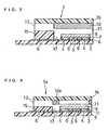
- FIG. 1is an exploded perspective view of a biosensor of this example
- FIG. 2is a sectional view of the biosensor.
- a silver pasteis printed by screen printing on an insulating base plate 2 and is dried by heating to form a working electrode lead 13 and a counter electrode lead 14 and a base of the electrode system that will be described below.
- a conductive carbon pasteis printed by screen printing and dried by heating to form an electrode system consisting of a working electrode 3 and a counter electrode 4.
- an insulating pasteis printed by screen printing so as to partially cover the electrode system and is dried by heating to form an insulating layer 6.
- An aqueous solution of carboxymethyl cellulosehereinafter referred to as CMC), which is a hydrophilic polymer, is dropped over the electrode system consisting of the working electrode 3 and the counter electrode 4, and is then dried by heating to form a CMC layer 7.
- an aqueous solution of potassium ferricyanide, which is an electron mediatoris dropped over the CMC layer 7 and is dried by heating, to form an electron mediator layer 8.
- the CMC layer 7 and the electron mediator layer 8are illustrated as being independent of each other, but in fact, they may be partially mixed with each other.
- a cover memberis fabricated by joining a top cover 16 and a mid cover 15 together.
- the mid cover 15is composed of two columnar members 15a and a short member 15b connecting them on the rear side.
- the cover memberhas a depression surrounded by the members 15a and 15b under the top cover 16.
- the cover memberis turned upside down, and an enzyme layer 10 is formed by dropping a mixed aqueous solution containing cholesterol esterase, cholesterol oxidase and optionally cholesterol dehydrogenase, serving as oxidoreductase, and a surfactant in the above-mentioned depression and freeze-drying it.
- the enzyme layer 10is formed in such a manner as to be accommodated in a sample solution supply pathway 17 formed by laminating the top cover 16, the mid cover 15 and the insulating base plate 2. Lastly, the insulating base plate 2 and the cover member are laminated in the positional relationship as shown by the dash-dotted lines in FIG. 1 , to produce a biosensor 1.
- the sample solution supply pathway 17, through which a sample solution is supplied to the electrode system,is formed by the insulating base plate 2, the mid cover 15 and the top cover 16 between the insulating base plate 2 and the top cover 16.
- a samplesuch as blood is supplied to the biosensor 1 from a sample supply inlet 11.
- An air vent 12allows air to escape upon supply of the sample, serving to facilitate the supply of the sample.
- the sample solution supply pathway 17is preferably 0.4 to 4 mm in width, 0.05 to 0.5 mm in height and 2 to 10 mm in length.
- the amount of a sample requiredis as small as 0.04 to 20 ⁇ l.
- the sample solution supply pathway 17is more preferably 0.5 to 2 mm in width, 0.05 to 0.2 mm in height and 3 to 5 mm in length, in which case the amount of a sample becomes 0.075 to 2.0 ⁇ l.
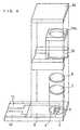
- FIG. 3is an exploded perspective view of a biosensor of this example
- FIG. 4is a sectional view of the biosensor.
- the biosensor of this embodimentis different from that of Embodiment 1 in the formation method of the enzyme layer and the position of the formed enzyme layer.
- An enzyme layer 10a of this embodimentis formed by screen printing a mixed aqueous solution containing an oxidoreductase, cholesterol esterase and a surfactant on the undersurface of a top cover 16 and drying it.
- the position of the enzyme layer 10ais set such that when projected onto a base plate 2, the enzyme layer 10a surrounds an electron mediator layer 8 without overlapping with the layer 8.
- the enzyme layer 10a of the cover memberis set such that when projected onto the base plate 2, it surrounds the electron mediator layer 8 without overlapping with the layer 8; therefore, it is possible to reduce the thickness of the sample solution supply pathway, and therefore, the volume of the sample solution supply pathway, while maintaining the separation of the oxidoreductase from the electron mediator. Accordingly, the amount of a sample necessary for the measurement can be reduced.
- the oxidoreductase and the electron mediatorcan be carried in closer vicinity, the oxidoreductase and the electron mediator are promptly mixed with each other upon supply of the sample, so that shortening the reaction time is possible.
- FIG. 5is a block diagram showing an example of the structure of a measuring system using the above-described biosensor.
- a voltage application means 21applies a voltage between the working electrode 3 and the counter electrode 4 from the leads 13 and 14 of the sensor 1.
- a current detection means 22 placed between the voltage application means 21 and the lead 14detects the current flowing between the working electrode 3 and the counter electrode 4.
- a display means 23 connected to the current detection means 22displays the current value detected by the current detection means 22 or the value obtained by converting the current into voltage.
- Embodiment 1a 0.5 wt% aqueous solution of CMC was dropped in an amount of 4 ⁇ l over the electrode system and was dried at 50°C for 15 minutes to form the CMC layer 7.
- a 75 mM aqueous solution of potassium ferricyanidewas dropped in an amount of 4 ⁇ l over the CMC layer 7 and was dried at 50°C for 15 minutes to form the electron mediator layer 8.
- a mixed aqueous solution containing 400 unit(U)/ml cholesterol oxidase, 900 U/ml cholesterol esterase, and 1.6 wt% Triton-X100(polyoxyethylene-octyl phenyl ether, a surfactant) was dropped in an amount of 0.5 ⁇ l at a predetermined position of the cover member and was freeze-dried to form the enzyme layer 10.
- the sample solution supply pathway 17is 2 mm in width, 0.1 mm in height and about 5.0 mm in length, and the area of the working electrode 3 is about 1.0 mm 2 .
- a biosensor of Comparative Example 1was produced in the same manner as in Example 1 except that cholesterol esterase and cholesterol oxidase were mixed into the electron mediator layer.
- cholesterol concentrationswere measured on a cholesterol-free PBS buffer solution (cholesterol concentration is 0 mg/dl and PBS designates phosphate buffered saline) and human serum having a cholesterol concentration of 105 mg/dl.
- the sample solutionwas supplied to the sample solution supply pathway 17 by bringing it into contact with the sample supply inlet 11; 3 minutes after that, a voltage of 500 mV was applied to the working electrode 3 with respect to the counter electrode 4, and 5 seconds after that, the value of the current (response value) flowing between the working electrode 3 and the counter electrode 4 was measured.
- Table 1shows changes in response value to the PBS buffer solution having a cholesterol concentration of 0 mg/dl
- Table 2shows changes in response value to the human serum having a cholesterol concentration of 105 mg/dl.
- Table 1Initial stage After storage Example 1 0.19 ⁇ A 0.22 ⁇ A Comparative Example 1 0. 56 ⁇ A 0.89 ⁇ A
- Table 2Initial stage After storage Example 1 1.53 ⁇ A 1.58 ⁇ A Comparative Example 1 2.12 ⁇ A 2.64 ⁇ A
- the response value of the biosensor of Example 1 to the cholesterol concentration of 0 mg/dlwas 0.19 ⁇ A, which was 0.37 ⁇ A lower than that of the biosensor of the comparative example.
- the biosensor of Example 1produced the effect of lowering the response value to the cholesterol concentration of 0 mg/dl, i.e., the blank value.
- the response value of the comparative example to the cholesterol concentration of 0 mg/dlincreased from 0.56 ⁇ A to 0.89 ⁇ A by 0.33 ⁇ A due to the 4-week storage at 30°C.
- the response value of Example 1 to the cholesterol concentration of 0 mg/dlincreased from 0.19 ⁇ A to 0.22 ⁇ A under the same storage conditions, which was a slight increase of 0.03 ⁇ A, and hence the increase in blank value due to the storage was suppressed.
- the response value of the comparative example to the cholesterol concentration of 105 mg/dlincreased from 2.12 ⁇ A to 2.64 ⁇ A by 0.52 ⁇ A due to the 4-week storage at 30°C.
- the response value of Example 1 to the cholesterol concentration of 105 mg/dlincreased from 1.53 ⁇ A to 1.58 ⁇ A under the same storage conditions, which was a slight increase of 0.05 ⁇ A, and hence the increase in blank value due to the storage was suppressed.
- Embodiment 2a mixed aqueous solution containing cholesterol oxidase, cholesterol esterase and Triton-X100 was used as the ink for printing the enzyme layer 10a.
- the obtained enzyme layer 10acontains 1.0 U cholesterol oxidase, 2.25 U cholesterol esterase and 8.0 ⁇ g Triton-X100.
- the enzyme layer 10ais about 0.7 mm in thickness, and the diameter of the middle hole is slightly greater than the outer shape of the counter electrode 4 (a circle 3.0 mm in diameter).
- the CMC layer 7 and the electron mediator layer 8were formed in the same manner as in Example 1, and their outer shapes are almost the same as the outer shape of the counter electrode 4.
- Example 1the cholesterol concentrations of the sample solutions were measured in the same procedure as in Example 1, and the results obtained were similar to those of Example 1.
- the CMC layer 7 and the electron mediator 8had a round shape, but they may be square, rectangular or oval. In either case, the enzyme layer 10 or 10a may be of any shape unless the oxidoreductase comes in contact with the electron mediator.
- potassium ferricyanidewas used as the electron mediator, but either one of p-benzoquinone and its derivatives, phenazine methosulfate, methylene blue, and ferrocene and its derivatives may also be used.
- the layer containing the electron mediatorwas formed by dropping the aqueous solution of the electron mediator onto the intended position of the layer and drying it by heating, but it may be formed by dropping an aqueous solution containing the electron mediator onto the predetermined position and freeze-drying it. Also, the layer containing the electron mediator may be formed by a method of screen printing an aqueous solution containing the electron mediator or by a method of impregnating a carrier disposed in the sample solution supply pathway with an aqueous solution containing the electron mediator and heat-drying it at 30 to 70°C or freeze-drying it.
- the layer containing the oxidoreductasewas formed by the method of dropping the aqueous solution of the oxidoreductase on the predetermined position and freeze-drying it or by the method of screen printing the aqueous solution containing the oxidoreductase, but it may also be formed by other methods.
- itmay be formed by a method of dropping an aqueous solution containing the oxidoreductase onto the predetermined position and heat-drying it at 30 to 70°C or by a method of dropping an aqueous solution containing the oxidoreductase onto a carrier disposed in the sample solution supply pathway, impregnating the carrier with the aqueous solution, and heat-drying it at 30 to 70 °C or freeze-drying it.
- the present inventioncan provide a biosensor of which blank value is low, of which response value, particularly blank value, is hardly changed by storage, and of which structure is simple. Further, by employing a structure that prevents the contact between an oxidoreductase and an electron mediator, the thickness of a sample supply solution supply pathway can be reduced, so that the necessary amount of a sample such as blood can be decreased. Further, since the oxidoreductase and the electron mediator can be carried in closer vicinity, the oxidoreductase and the electron mediator are promptly mixed with each other upon supply of the sample, so that shortening the reaction time is possible.
Landscapes
- Chemical & Material Sciences (AREA)
- Organic Chemistry (AREA)
- Life Sciences & Earth Sciences (AREA)
- Zoology (AREA)
- Wood Science & Technology (AREA)
- Proteomics, Peptides & Aminoacids (AREA)
- Health & Medical Sciences (AREA)
- Engineering & Computer Science (AREA)
- Microbiology (AREA)
- Biochemistry (AREA)
- Physics & Mathematics (AREA)
- Molecular Biology (AREA)
- Biotechnology (AREA)
- Biophysics (AREA)
- Analytical Chemistry (AREA)
- Immunology (AREA)
- Bioinformatics & Cheminformatics (AREA)
- General Engineering & Computer Science (AREA)
- General Health & Medical Sciences (AREA)
- Genetics & Genomics (AREA)
- Measuring Or Testing Involving Enzymes Or Micro-Organisms (AREA)
- Investigating Or Analysing Biological Materials (AREA)
- Apparatus Associated With Microorganisms And Enzymes (AREA)
Abstract
Description
- The present invention relates to a biosensor for quantifying a substrate contained in a sample, such as blood, plasma and serum.
- Various biosensors have conventionally been proposed to quantify a specific component of a sample such as blood, and the following sensor is known as one example (Japanese Laid-Open Patent Publication No.
Sho 63-317096 - This biosensor is produced by forming an electrode system comprising a working electrode, a counter electrode and a reference electrode on an insulating base plate by a method such as screen printing and forming a reaction layer comprising an oxidoreductase and an electron mediator on the electrode system.
- When a sample containing a substrate is dropped on the reaction layer of the biosensor thus produced, dissolution of the reaction layer takes place to cause a reaction between the oxidoreductase and the substrate, which is accompanied by reduction of the electron mediator. After the lapse of a certain period of time, the reduced electron mediator is electrochemically oxidized by the electrode system, and based on the oxidation current value obtained, the substrate in the sample solution is quantified.
- In the biosensor having the above-described constitution, the oxidoreductase and the electron mediator are usually mixed with each other on the electrode system. This is aimed at saving the trouble of mixing or stirring the sample and causing the reaction between the oxidoreductase and the electron mediator to proceed effectively such that quick quantification of the substrate becomes possible.
- However, the biosensor in which the oxidoreductase and the electron mediator are mixed or in contact with each other has such a problem that the response value to a sample solution having a substrate concentration of 0 mg/dl (hereinafter referred to as blank value) is not 0 but higher than 0. Further, another problem is that in comparison with the response value immediately after the production of the biosensor (hereinafter referred to as initial stage), the blank value and the response value to a sample solution having the same substrate concentration increase as the storage period becomes longer. The response value is changed by storage becomes a problem in that the reliability is low.
- In view of the above problems, an object of the present invention is to provide a biosensor of which blank value is low, of which response value, particularly blank value, is hardly changed by storage, and of which structure is simple.
- Another object of the present invention is to provide a biosensor suited for quantification of cholesterol in particular.
- European patent application
EP-A-1 124 131 (published on 18.08.2001, priority date 27.01.2000) shows: - a biosensor comprising an electrically insulating base plate, an electrode system formed on said base plate, a cover member which is joined to said base plate to form a sample solution supply path way for supplying a sample solution to said electrode system between the cover member and the base plate, and a reagent system comprising at least cholesterol oxidase, cholesterol esterase, a surfactant and an electron mediator dispensed in said sample solution pathway, wherein said electron mediator is provided on said base plate and said cholesterol oxidase said cholesterol esterase, and said surfactant is provided on said cover member such that said electron mediator and said cholesterol oxidase are not in contact with each other.
- The present invention provides a biosensor comprising: an electrically insulating base plate; an electrode system comprising a working electrode and a counter electrode formed on the base plate; a cover member which is joined to the base plate to form a sample solution supply pathway for supplying a sample solution to the electrode system between the cover member and the base plate; and a reagent system comprising at least cholesterol oxidase, cholesterol esterase, a surfactant and an electron mediator disposed in the sample solution supply pathway, wherein the electron mediator is provided on the base plate and said cholesterol oxidase and said surfactant are provided on the cover member such that they are not in contact with said electron mediator, and
wherein said cholesterol oxidase is positioned, when projected onto the base plate, so as not to overlap with the position of the electron mediator. - The present invention also provides a measuring system comprising: the above-described biosensor; a voltage application means for applying a voltage between the working electrode and the counter electrode; and a signal detection means for detecting an electric signal between the working electrode and the counter electrode upon application of the voltage.
- It is preferable that the measuring system further comprise a display means for displaying the signal detected by the signal detection means.
FIG. 1 is an exploded perspective view of a biosensor.FIG. 2 is a sectional view of the biosensor.FIG. 3 is an exploded perspective view of a biosensor in an example of the present invention.FIG. 4 is a sectional view of the biosensor.FIG. 5 is a block diagram showing the circuit structure of a measuring system in one example of the present invention.- The present invention relates to a biosensor comprising: an electrically insulating base plate; an electrode system comprising a working electrode and a counter electrode formed on the base plate; a cover member which is joined to the base plate to form a sample solution supply pathway for supplying a sample solution to the electrode system between the cover member and the base plate; and a reagent system comprising at least cholesterol oxidase, cholesterol esterase, a surfactant and an electron mediator disposed in the sample solution supply pathway, wherein the electron mediator is provided on the base plate and said cholesterol oxidase and said surfactant are provided on the cover member such that they are not in contact with said electron mediator.
- According to the present invention, the electron mediator and the oxidoreductase are prevented from coming in contact with each other in a simple structure. Thus, after the production of the biosensor, the oxidoreductase and the electron mediator do not react with each other in the biosensor, so that the blank value can be kept low and the change in the response value due to storage can be suppressed.
- The cholesterol oxidase is positioned, when projected onto the base plate, so as not to overlap with the position of the electron mediator.
- This can reduce the volume of the sample solution supply pathway while separating the oxidoreductase from the electron mediator.
- The reagent system comprises a surfactant provided on the cover member. It is preferable that the surfactant be mixed with the oxidoreductase.
- A preferable biosensor in accordance with the present invention is designed for quantifying serum cholesterol level as a diagnostic index, and the reagent system comprises: at least cholesterol oxidase and optionally cholesterol dehydrogenase; cholesterol esterase which is an enzyme catalyzing the conversion of cholesterol ester into cholesterol; and a surfactant.
- Cholesterol in blood or serum is contained in lipoprotein having a micelle structure. Inclusion of an appropriate surfactant in the reagent system improves the reactivity of at least one of cholesterol oxidase and cholesterol dehydrogenase or cholesterol esterase to the cholesterol contained in lipoprotein.
- The surfactant used for the above purpose may be either an ionic surfactant or a non-ionic surfactant. Such examples include polyoxyethylene-octyl phenyl ether, cholic acid or its salts, deoxycholic acid or its salts, salts of fatty acid, salts of alkylsulfate ester, salts of polyoxyethylene alkyl ether sulfate ester, alkyl benzene sulfonates, alkyl naphthalene sulfonates, alkyl sulfosuccinates, alkyl diphenyl ether disulfonates, alkyl phosphates, naphthalenesulfonic acid formalin condensation products, polycarboxylic acid type polymer surfactants, polyoxyethylene alkyl ethers, polyoxyalkylene alkyl ethers, polyoxyethylene derivatives, sorbitan fatty acid esters, polyoxyethylene sorbitan fatty acid esters, polyoxyethylene sorbitol fatty acid esters, glycerin fatty acid esters, polyoxyethylene fatty acid esters, polyoxyethylene alkyl amines, alkyl alkanol amides, alkyl amine salts, quaternary ammonium salts, alkyl betaines, and amine oxides. Among them, polyoxyethylene-octyl phenyl ether is particularly preferable.
- Since the solubilizing action of the surfactant on lipoprotein varies depending on the type of the surfactant, two or more of the above-listed surfactants may be used at one time.
- In another preferable mode of the present invention, at least one of the electron mediator and the oxidoreductase is formed by freeze-drying its aqueous solution.
- The layer of the electron mediator and/or the oxidoreductase formed by freeze-drying has an improved dissolution, so that the time required for the whole measurement can be shortened. Since the reaction by the oxidoreductase is the first step for obtaining a response value, it is particularly preferable to form the layer of the oxidoreductase by freeze-drying, because the oxidoreductase can be promptly dissolved upon supplying a sample solution.
- In still another preferable mode of the present invention, at least one of the electron mediator and the oxidoreductase is carried by a carrier.
- As the carrier, any carrier capable of carrying a reagent or reagents inside or on the surface of the carrier may be used, and such examples include filter paper, glass filter, cellulose fiber, paper and cork. When filter paper is used, the reagent(s) are primarily carried inside the filter paper, and when paper is used, the reagent(s) are carried on the surface of the paper; therefore, there is a difference between them. Among these carriers, glass filter and cellulose fiber are preferable because there is less nonspecific adsorption of the oxidoreductase to these carriers.
- With respect to the electron mediator which can be used in the biosensor of the present invention, there is no particular limitation, but potassium ferricyanide, p-benzoquinone, derivatives of p-benzoquinone, phenazine methosulfate, methylene blue, ferrocene and derivatives of ferrocene may be used. Among them, potassium ferricyanide is preferable because it is stable in the presence of oxygen.
- As the oxidoreductase, cholesterol oxidase, and optionally cholesterol dehydrogenase or the like is selected, as appropriate, depending on the substrate to be measured.
- As the insulating base plate and the cover member, any electrically insulating material having rigidity may be used. Such examples include thermoplastic resins, such as polyethylene, polyethylene terephthalate, polystyrene, poly vinyl chloride, polyamide and saturated polyester, or thermosetting resins, such as urea resin, melamine resin, phenol resin, epoxy resin and unsaturated polyester resin.
- A preferable biosensor of the present invention has an electron mediator layer which is formed over the electrode system on the base plate. In order to prevent the direct contact between the electron mediator and the electrode system and securely carry the electron mediator layer, it is preferable to form a hydrophilic polymer layer on the electrode system and form the electron mediator layer on the hydrophilic polymer layer.
- Also, when the electrode system is constituted of a silver paste base and a carbon paste on the base, a sample solution permeates the silver layer of the electrode base by the action of the surfactant of the reagent system dissolved in the sample. Thus, when a potential is applied onto the electrodes for measuring the response current of the sensor, the silver layer may affect the electrochemical reaction, resulting in an increase in the response current value. When the electrode system is coated with the hydrophilic polymer layer, the permeation of the surfactant into the silver layer can be lessened.
- The hydrophilic polymer constituting the hydrophilic polymer layer may be any material of which aqueous solution has viscosity, and such examples include cellulose such as carboxymethyl cellulose, hydroxyethyl cellulose, hydroxypropyl cellulose, methyl cellulose, ethyl cellulose, ethylhydroxyethyl cellulose and carboxyethyl cellulose, polyvinyl pyrrolidone, polyvinyl alcohol, polyamino acid such as polylysine, polystyrene sulfonate, gelatin and its derivatives, a polymer of acrylic acid and its salts, a polymer of methacrylic acid and its salts, starch and its derivatives, a polymer of maleic anhydride and its salts, agarose gel and its derivatives.
- The material of the working electrode and the counter electrode may be any conductive material, and such examples include carbon, gold, palladium and platinum.
- The electrode system comprising the working electrode and the counter electrode formed on the insulating base plate may further comprise a reference electrode.
- As the sample to be measured by the biosensor of the present invention, a body fluid may be cited. The body fluid may be either one of blood, plasma, lymph fluid, interstitial fluid and sweat. The substrate to be measured is cholesterol, glucose, or the like contained in the body fluid.
- In the following, the structure of the biosensor of the present invention will be described with reference to drawings. The structural drawings are used to facilitate the understanding, and the relative size and positional relationship of the respective elements are not necessarily accurate.
FIG. 1 is an exploded perspective view of a biosensor of this example, andFIG. 2 is a sectional view of the biosensor.- A silver paste is printed by screen printing on an insulating
base plate 2 and is dried by heating to form a workingelectrode lead 13 and acounter electrode lead 14 and a base of the electrode system that will be described below. Subsequently, a conductive carbon paste is printed by screen printing and dried by heating to form an electrode system consisting of a workingelectrode 3 and acounter electrode 4. Further, an insulating paste is printed by screen printing so as to partially cover the electrode system and is dried by heating to form an insulatinglayer 6. An aqueous solution of carboxymethyl cellulose (hereinafter referred to as CMC), which is a hydrophilic polymer, is dropped over the electrode system consisting of the workingelectrode 3 and thecounter electrode 4, and is then dried by heating to form aCMC layer 7. Thereafter, an aqueous solution of potassium ferricyanide, which is an electron mediator, is dropped over theCMC layer 7 and is dried by heating, to form anelectron mediator layer 8. In these figures, theCMC layer 7 and theelectron mediator layer 8 are illustrated as being independent of each other, but in fact, they may be partially mixed with each other. - Next, a cover member is fabricated by joining a
top cover 16 and amid cover 15 together. Themid cover 15 is composed of twocolumnar members 15a and ashort member 15b connecting them on the rear side. The cover member has a depression surrounded by themembers top cover 16. The cover member is turned upside down, and anenzyme layer 10 is formed by dropping a mixed aqueous solution containing cholesterol esterase, cholesterol oxidase and optionally cholesterol dehydrogenase, serving as oxidoreductase, and a surfactant in the above-mentioned depression and freeze-drying it. Theenzyme layer 10 is formed in such a manner as to be accommodated in a samplesolution supply pathway 17 formed by laminating thetop cover 16, themid cover 15 and the insulatingbase plate 2. Lastly, the insulatingbase plate 2 and the cover member are laminated in the positional relationship as shown by the dash-dotted lines inFIG. 1 , to produce abiosensor 1. - In the
biosensor 1, the samplesolution supply pathway 17, through which a sample solution is supplied to the electrode system, is formed by the insulatingbase plate 2, themid cover 15 and thetop cover 16 between the insulatingbase plate 2 and thetop cover 16. A sample such as blood is supplied to thebiosensor 1 from asample supply inlet 11. Anair vent 12 allows air to escape upon supply of the sample, serving to facilitate the supply of the sample. - In the sensor having the above-described structure, the sample
solution supply pathway 17 is preferably 0.4 to 4 mm in width, 0.05 to 0.5 mm in height and 2 to 10 mm in length. For the sensor of such size, the amount of a sample required is as small as 0.04 to 20 µl. The samplesolution supply pathway 17 is more preferably 0.5 to 2 mm in width, 0.05 to 0.2 mm in height and 3 to 5 mm in length, in which case the amount of a sample becomes 0.075 to 2.0 µl. FIG. 3 is an exploded perspective view of a biosensor of this example, andFIG. 4 is a sectional view of the biosensor.- The biosensor of this embodiment is different from that of
Embodiment 1 in the formation method of the enzyme layer and the position of the formed enzyme layer. Anenzyme layer 10a of this embodiment is formed by screen printing a mixed aqueous solution containing an oxidoreductase, cholesterol esterase and a surfactant on the undersurface of atop cover 16 and drying it. The position of theenzyme layer 10a is set such that when projected onto abase plate 2, theenzyme layer 10a surrounds anelectron mediator layer 8 without overlapping with thelayer 8. - In the biosensor of this embodiment, the
enzyme layer 10a of the cover member is set such that when projected onto thebase plate 2, it surrounds theelectron mediator layer 8 without overlapping with thelayer 8; therefore, it is possible to reduce the thickness of the sample solution supply pathway, and therefore, the volume of the sample solution supply pathway, while maintaining the separation of the oxidoreductase from the electron mediator. Accordingly, the amount of a sample necessary for the measurement can be reduced. - Further, since the oxidoreductase and the electron mediator can be carried in closer vicinity, the oxidoreductase and the electron mediator are promptly mixed with each other upon supply of the sample, so that shortening the reaction time is possible.
FIG. 5 is a block diagram showing an example of the structure of a measuring system using the above-described biosensor. A voltage application means 21 applies a voltage between the workingelectrode 3 and thecounter electrode 4 from theleads sensor 1. A current detection means 22 placed between the voltage application means 21 and thelead 14 detects the current flowing between the workingelectrode 3 and thecounter electrode 4. A display means 23 connected to the current detection means 22 displays the current value detected by the current detection means 22 or the value obtained by converting the current into voltage.- In the following, the present invention will be more specifically described by way of examples. As one example of the biosensor, a cholesterol sensor will be described, but the following examples are not to be construed as limiting in any way the present invention.
- In
Embodiment 1, a 0.5 wt% aqueous solution of CMC was dropped in an amount of 4 µl over the electrode system and was dried at 50°C for 15 minutes to form theCMC layer 7. A 75 mM aqueous solution of potassium ferricyanide was dropped in an amount of 4 µl over theCMC layer 7 and was dried at 50°C for 15 minutes to form theelectron mediator layer 8. Meanwhile, a mixed aqueous solution containing 400 unit(U)/ml cholesterol oxidase, 900 U/ml cholesterol esterase, and 1.6 wt% Triton-X100 (polyoxyethylene-octyl phenyl ether, a surfactant) was dropped in an amount of 0.5 µl at a predetermined position of the cover member and was freeze-dried to form theenzyme layer 10. The samplesolution supply pathway 17 is 2 mm in width, 0.1 mm in height and about 5.0 mm in length, and the area of the workingelectrode 3 is about 1.0 mm2. - A biosensor of Comparative Example 1 was produced in the same manner as in Example 1 except that cholesterol esterase and cholesterol oxidase were mixed into the electron mediator layer.
- Next, using the biosensors of Example 1 and Comparative Example 1, cholesterol concentrations were measured on a cholesterol-free PBS buffer solution (cholesterol concentration is 0 mg/dl and PBS designates phosphate buffered saline) and human serum having a cholesterol concentration of 105 mg/dl. The sample solution was supplied to the sample
solution supply pathway 17 by bringing it into contact with thesample supply inlet 11; 3 minutes after that, a voltage of 500 mV was applied to the workingelectrode 3 with respect to thecounter electrode 4, and 5 seconds after that, the value of the current (response value) flowing between the workingelectrode 3 and thecounter electrode 4 was measured. - Table 1 shows changes in response value to the PBS buffer solution having a cholesterol concentration of 0 mg/dl, and Table 2 shows changes in response value to the human serum having a cholesterol concentration of 105 mg/dl. On each of the sample solutions, a comparison was made between the response value at the initial stage of the biosensor and the response value after a 4-week storage of the biosensor at 30°C.
Table 1 Initial stage After storage Example 1 0.19 µA 0.22 µA Comparative Example 1 0. 56 µA 0.89 µA Table 2 Initial stage After storage Example 1 1.53 µA 1.58 µA Comparative Example 1 2.12 µA 2.64 µA - As is clear from Table 1, at the initial stage, the response value of the biosensor of Example 1 to the cholesterol concentration of 0 mg/dl was 0.19 µA, which was 0.37 µA lower than that of the biosensor of the comparative example. Thus, the biosensor of Example 1 produced the effect of lowering the response value to the cholesterol concentration of 0 mg/dl, i.e., the blank value.
- As is also clear from Table 1, the response value of the comparative example to the cholesterol concentration of 0 mg/dl increased from 0.56 µA to 0.89 µA by 0.33 µA due to the 4-week storage at 30°C. On the other hand, the response value of Example 1 to the cholesterol concentration of 0 mg/dl increased from 0.19 µA to 0.22 µA under the same storage conditions, which was a slight increase of 0.03 µA, and hence the increase in blank value due to the storage was suppressed.
- Further, as is clear from Table 2, the response value of the comparative example to the cholesterol concentration of 105 mg/dl increased from 2.12 µA to 2.64 µA by 0.52 µA due to the 4-week storage at 30°C. On the other hand, the response value of Example 1 to the cholesterol concentration of 105 mg/dl increased from 1.53 µA to 1.58 µA under the same storage conditions, which was a slight increase of 0.05 µA, and hence the increase in blank value due to the storage was suppressed.
- In
Embodiment 2, a mixed aqueous solution containing cholesterol oxidase, cholesterol esterase and Triton-X100 was used as the ink for printing theenzyme layer 10a. The obtainedenzyme layer 10a contains 1.0 U cholesterol oxidase, 2.25 U cholesterol esterase and 8.0 µg Triton-X100. Theenzyme layer 10a is about 0.7 mm in thickness, and the diameter of the middle hole is slightly greater than the outer shape of the counter electrode 4 (a circle 3.0 mm in diameter). TheCMC layer 7 and theelectron mediator layer 8 were formed in the same manner as in Example 1, and their outer shapes are almost the same as the outer shape of thecounter electrode 4. - Using this biosensor, the cholesterol concentrations of the sample solutions were measured in the same procedure as in Example 1, and the results obtained were similar to those of Example 1.
- In Examples 1 and 2, the
CMC layer 7 and theelectron mediator 8 had a round shape, but they may be square, rectangular or oval. In either case, theenzyme layer - Also, potassium ferricyanide was used as the electron mediator, but either one of p-benzoquinone and its derivatives, phenazine methosulfate, methylene blue, and ferrocene and its derivatives may also be used.
- An explanation was given of the reagent system containing cholesterol esterase, cholesterol oxidase and the surfactant to measure the total cholesterol level of blood or the like, but glucose oxidase, glucose dehydrogenase or the like may be used as the oxidoreductase in a system measuring the amount of glucose.
- In the foregoing examples, the layer containing the electron mediator was formed by dropping the aqueous solution of the electron mediator onto the intended position of the layer and drying it by heating, but it may be formed by dropping an aqueous solution containing the electron mediator onto the predetermined position and freeze-drying it. Also, the layer containing the electron mediator may be formed by a method of screen printing an aqueous solution containing the electron mediator or by a method of impregnating a carrier disposed in the sample solution supply pathway with an aqueous solution containing the electron mediator and heat-drying it at 30 to 70°C or freeze-drying it.
- The layer containing the oxidoreductase was formed by the method of dropping the aqueous solution of the oxidoreductase on the predetermined position and freeze-drying it or by the method of screen printing the aqueous solution containing the oxidoreductase, but it may also be formed by other methods. For example, it may be formed by a method of dropping an aqueous solution containing the oxidoreductase onto the predetermined position and heat-drying it at 30 to 70°C or by a method of dropping an aqueous solution containing the oxidoreductase onto a carrier disposed in the sample solution supply pathway, impregnating the carrier with the aqueous solution, and heat-drying it at 30 to 70 °C or freeze-drying it.
- As described above, the present invention can provide a biosensor of which blank value is low, of which response value, particularly blank value, is hardly changed by storage, and of which structure is simple. Further, by employing a structure that prevents the contact between an oxidoreductase and an electron mediator, the thickness of a sample supply solution supply pathway can be reduced, so that the necessary amount of a sample such as blood can be decreased. Further, since the oxidoreductase and the electron mediator can be carried in closer vicinity, the oxidoreductase and the electron mediator are promptly mixed with each other upon supply of the sample, so that shortening the reaction time is possible.
Claims (12)
- A biosensor comprising: an electrically insulating base plate (2); an electrode system comprising a working electrode (3) and a counter electrode (4) formed on said base plate (2); a cover member (15, 16) which is joined to said base plate to form a sample solution supply pathway (17) for supplying a sample solution to said electrode system between the cover member (15, 16) and the base plate (2); and a reagent system comprising at least cholesterol oxidase, cholesterol esterase, a surfactant and an electron mediator disposed in said sample solution supply pathway, wherein said electron mediator is provided on said base plate, and said cholesterol oxidase and said surfactant are provided on said cover member such that they are not in contact with said electron mediator, and wherein said cholesterol oxidase is positioned, when projected onto said base plate, so as not to overlap with the position of said electron mediator.
- A biosensor in accordance with claim 1,
wherein said surfactant is mixed with said cholesterol oxidase. - A biosensor in accordance with claim 1or claim 2,
wherein at least one of the electron mediator and the cholesterol oxidase is produced by freeze-drying its aqueous solution. - A biosensor in accordance with any one of the preceding claims,
wherein at least one of the electron mediator and the cholesterol oxidase is carried by a carrier. - A biosensor in accordance with claim 4, wherein said carrier is selected from the group consisting of filter paper, glass filter, cellulose fiber, paper and cork.
- A biosensor in accordance with any one of the preceding claims,
wherein said cholesterol esterase is provided on said cover member. - A biosensor in accordance with any one of the preceding claims, wherein said electron mediator is provided over said electrode system with a hydrophilic polymer layer interposed therebetween.
- A biosensor in accordance with any one of the preceding claims, wherein said electron mediator is selected from the group consisting of potassium ferricyanide, p-benzoquinone, derivatives of p-benzoquinone, phenazine methosulfate, methylene blue, ferrocene and derivatives of ferrocene.
- A biosensor in accordance with any one of the preceding claims, which is designed to measure a body fluid.
- A biosensor in accordance with claim 9,
wherein said body fluid is blood, plasma, lymph or interstitial fluid. - A measuring system comprising: the biosensor as recited in any one of claims 1 to 10; a voltage application means for applying a voltage between said working electrode and said counter electrode; and a signal detection means for detecting an electric signal between the working electrode and the counter electrode upon application of the voltage.
- A measuring system in accordance with claim 11,
further comprising a display means for displaying the signal detected by said signal detection means.
Applications Claiming Priority (3)
| Application Number | Priority Date | Filing Date | Title |
|---|---|---|---|
| JP2001008473 | 2001-01-17 | ||
| JP2001008473 | 2001-01-17 | ||
| PCT/JP2002/000108WO2002057767A1 (en) | 2001-01-17 | 2002-01-10 | Biosensor |
Publications (3)
| Publication Number | Publication Date |
|---|---|
| EP1353169A1 EP1353169A1 (en) | 2003-10-15 |
| EP1353169A4 EP1353169A4 (en) | 2007-01-17 |
| EP1353169B1true EP1353169B1 (en) | 2012-06-13 |
Family
ID=18876086
Family Applications (1)
| Application Number | Title | Priority Date | Filing Date |
|---|---|---|---|
| EP02732186AExpired - LifetimeEP1353169B1 (en) | 2001-01-17 | 2002-01-10 | Biosensor |
Country Status (5)
| Country | Link |
|---|---|
| US (1) | US7267750B2 (en) |
| EP (1) | EP1353169B1 (en) |
| JP (1) | JP3971997B2 (en) |
| CN (1) | CN1226615C (en) |
| WO (1) | WO2002057767A1 (en) |
Families Citing this family (74)
| Publication number | Priority date | Publication date | Assignee | Title |
|---|---|---|---|---|
| US6391005B1 (en) | 1998-03-30 | 2002-05-21 | Agilent Technologies, Inc. | Apparatus and method for penetration with shaft having a sensor for sensing penetration depth |
| US20050103624A1 (en) | 1999-10-04 | 2005-05-19 | Bhullar Raghbir S. | Biosensor and method of making |
| US8641644B2 (en) | 2000-11-21 | 2014-02-04 | Sanofi-Aventis Deutschland Gmbh | Blood testing apparatus having a rotatable cartridge with multiple lancing elements and testing means |
| US9795747B2 (en) | 2010-06-02 | 2017-10-24 | Sanofi-Aventis Deutschland Gmbh | Methods and apparatus for lancet actuation |
| US7344507B2 (en) | 2002-04-19 | 2008-03-18 | Pelikan Technologies, Inc. | Method and apparatus for lancet actuation |
| US8337419B2 (en) | 2002-04-19 | 2012-12-25 | Sanofi-Aventis Deutschland Gmbh | Tissue penetration device |
| US9427532B2 (en) | 2001-06-12 | 2016-08-30 | Sanofi-Aventis Deutschland Gmbh | Tissue penetration device |
| EP1395185B1 (en) | 2001-06-12 | 2010-10-27 | Pelikan Technologies Inc. | Electric lancet actuator |
| JP4209767B2 (en) | 2001-06-12 | 2009-01-14 | ペリカン テクノロジーズ インコーポレイテッド | Self-optimized cutting instrument with adaptive means for temporary changes in skin properties |
| US9226699B2 (en) | 2002-04-19 | 2016-01-05 | Sanofi-Aventis Deutschland Gmbh | Body fluid sampling module with a continuous compression tissue interface surface |
| US7749174B2 (en) | 2001-06-12 | 2010-07-06 | Pelikan Technologies, Inc. | Method and apparatus for lancet launching device intergrated onto a blood-sampling cartridge |
| US7041068B2 (en) | 2001-06-12 | 2006-05-09 | Pelikan Technologies, Inc. | Sampling module device and method |
| US7981056B2 (en) | 2002-04-19 | 2011-07-19 | Pelikan Technologies, Inc. | Methods and apparatus for lancet actuation |
| US7297122B2 (en) | 2002-04-19 | 2007-11-20 | Pelikan Technologies, Inc. | Method and apparatus for penetrating tissue |
| US9248267B2 (en) | 2002-04-19 | 2016-02-02 | Sanofi-Aventis Deustchland Gmbh | Tissue penetration device |
| US8784335B2 (en) | 2002-04-19 | 2014-07-22 | Sanofi-Aventis Deutschland Gmbh | Body fluid sampling device with a capacitive sensor |
| US8267870B2 (en) | 2002-04-19 | 2012-09-18 | Sanofi-Aventis Deutschland Gmbh | Method and apparatus for body fluid sampling with hybrid actuation |
| US8360992B2 (en) | 2002-04-19 | 2013-01-29 | Sanofi-Aventis Deutschland Gmbh | Method and apparatus for penetrating tissue |
| US7976476B2 (en) | 2002-04-19 | 2011-07-12 | Pelikan Technologies, Inc. | Device and method for variable speed lancet |
| US8221334B2 (en) | 2002-04-19 | 2012-07-17 | Sanofi-Aventis Deutschland Gmbh | Method and apparatus for penetrating tissue |
| US9314194B2 (en) | 2002-04-19 | 2016-04-19 | Sanofi-Aventis Deutschland Gmbh | Tissue penetration device |
| US7491178B2 (en) | 2002-04-19 | 2009-02-17 | Pelikan Technologies, Inc. | Method and apparatus for penetrating tissue |
| US9795334B2 (en) | 2002-04-19 | 2017-10-24 | Sanofi-Aventis Deutschland Gmbh | Method and apparatus for penetrating tissue |
| US7331931B2 (en) | 2002-04-19 | 2008-02-19 | Pelikan Technologies, Inc. | Method and apparatus for penetrating tissue |
| US8579831B2 (en) | 2002-04-19 | 2013-11-12 | Sanofi-Aventis Deutschland Gmbh | Method and apparatus for penetrating tissue |
| US8372016B2 (en) | 2002-04-19 | 2013-02-12 | Sanofi-Aventis Deutschland Gmbh | Method and apparatus for body fluid sampling and analyte sensing |
| US7547287B2 (en) | 2002-04-19 | 2009-06-16 | Pelikan Technologies, Inc. | Method and apparatus for penetrating tissue |
| US7229458B2 (en) | 2002-04-19 | 2007-06-12 | Pelikan Technologies, Inc. | Method and apparatus for penetrating tissue |
| US7901362B2 (en) | 2002-04-19 | 2011-03-08 | Pelikan Technologies, Inc. | Method and apparatus for penetrating tissue |
| US7708701B2 (en) | 2002-04-19 | 2010-05-04 | Pelikan Technologies, Inc. | Method and apparatus for a multi-use body fluid sampling device |
| US7232451B2 (en) | 2002-04-19 | 2007-06-19 | Pelikan Technologies, Inc. | Method and apparatus for penetrating tissue |
| US7909778B2 (en) | 2002-04-19 | 2011-03-22 | Pelikan Technologies, Inc. | Method and apparatus for penetrating tissue |
| US8702624B2 (en) | 2006-09-29 | 2014-04-22 | Sanofi-Aventis Deutschland Gmbh | Analyte measurement device with a single shot actuator |
| US7674232B2 (en) | 2002-04-19 | 2010-03-09 | Pelikan Technologies, Inc. | Method and apparatus for penetrating tissue |
| US7892183B2 (en) | 2002-04-19 | 2011-02-22 | Pelikan Technologies, Inc. | Method and apparatus for body fluid sampling and analyte sensing |
| CN100451639C (en) | 2002-10-25 | 2009-01-14 | 爱科来株式会社 | Analytical tool |
| US8574895B2 (en) | 2002-12-30 | 2013-11-05 | Sanofi-Aventis Deutschland Gmbh | Method and apparatus using optical techniques to measure analyte levels |
| DE602004028463D1 (en) | 2003-05-30 | 2010-09-16 | Pelikan Technologies Inc | METHOD AND DEVICE FOR INJECTING LIQUID |
| US7850621B2 (en) | 2003-06-06 | 2010-12-14 | Pelikan Technologies, Inc. | Method and apparatus for body fluid sampling and analyte sensing |
| WO2006001797A1 (en) | 2004-06-14 | 2006-01-05 | Pelikan Technologies, Inc. | Low pain penetrating |
| US8058077B2 (en) | 2003-06-20 | 2011-11-15 | Roche Diagnostics Operations, Inc. | Method for coding information on a biosensor test strip |
| US7452457B2 (en) | 2003-06-20 | 2008-11-18 | Roche Diagnostics Operations, Inc. | System and method for analyte measurement using dose sufficiency electrodes |
| US8206565B2 (en) | 2003-06-20 | 2012-06-26 | Roche Diagnostics Operation, Inc. | System and method for coding information on a biosensor test strip |
| US8148164B2 (en) | 2003-06-20 | 2012-04-03 | Roche Diagnostics Operations, Inc. | System and method for determining the concentration of an analyte in a sample fluid |
| US7718439B2 (en) | 2003-06-20 | 2010-05-18 | Roche Diagnostics Operations, Inc. | System and method for coding information on a biosensor test strip |
| US7597793B2 (en) | 2003-06-20 | 2009-10-06 | Roche Operations Ltd. | System and method for analyte measurement employing maximum dosing time delay |
| JP4447009B2 (en) | 2003-06-20 | 2010-04-07 | エフ ホフマン−ラ ロッシュ アクチェン ゲゼルシャフト | Test strip with slot vent opening |
| US7645421B2 (en) | 2003-06-20 | 2010-01-12 | Roche Diagnostics Operations, Inc. | System and method for coding information on a biosensor test strip |
| US7645373B2 (en) | 2003-06-20 | 2010-01-12 | Roche Diagnostic Operations, Inc. | System and method for coding information on a biosensor test strip |
| US8071030B2 (en) | 2003-06-20 | 2011-12-06 | Roche Diagnostics Operations, Inc. | Test strip with flared sample receiving chamber |
| US8282576B2 (en) | 2003-09-29 | 2012-10-09 | Sanofi-Aventis Deutschland Gmbh | Method and apparatus for an improved sample capture device |
| EP1680014A4 (en) | 2003-10-14 | 2009-01-21 | Pelikan Technologies Inc | METHOD AND DEVICE FOR A VARIABLE USER INTERFACE |
| EP1707953B1 (en)* | 2003-12-04 | 2015-07-01 | Panasonic Healthcare Holdings Co., Ltd. | Method of measuring hematocrit (Hct) |
| CN100472210C (en) | 2003-12-04 | 2009-03-25 | 松下电器产业株式会社 | Method for measuring blood components and sensor and measuring device used in the method |
| US8668656B2 (en) | 2003-12-31 | 2014-03-11 | Sanofi-Aventis Deutschland Gmbh | Method and apparatus for improving fluidic flow and sample capture |
| US7822454B1 (en) | 2005-01-03 | 2010-10-26 | Pelikan Technologies, Inc. | Fluid sampling device with improved analyte detecting member configuration |
| EP3115777B1 (en)* | 2004-04-19 | 2020-01-08 | PHC Holdings Corporation | Method for measuring blood components |
| WO2006011062A2 (en) | 2004-05-20 | 2006-02-02 | Albatros Technologies Gmbh & Co. Kg | Printable hydrogel for biosensors |
| WO2005120365A1 (en) | 2004-06-03 | 2005-12-22 | Pelikan Technologies, Inc. | Method and apparatus for a fluid sampling device |
| US9775553B2 (en) | 2004-06-03 | 2017-10-03 | Sanofi-Aventis Deutschland Gmbh | Method and apparatus for a fluid sampling device |
| US7556723B2 (en) | 2004-06-18 | 2009-07-07 | Roche Diagnostics Operations, Inc. | Electrode design for biosensor |
| US7569126B2 (en) | 2004-06-18 | 2009-08-04 | Roche Diagnostics Operations, Inc. | System and method for quality assurance of a biosensor test strip |
| US8652831B2 (en) | 2004-12-30 | 2014-02-18 | Sanofi-Aventis Deutschland Gmbh | Method and apparatus for analyte measurement test time |
| CN101779120B (en)* | 2007-07-26 | 2013-11-27 | 埃葛梅崔克斯股份有限公司 | Electrochemical test strips |
| EP2265324B1 (en) | 2008-04-11 | 2015-01-28 | Sanofi-Aventis Deutschland GmbH | Integrated analyte measurement system |
| US9375169B2 (en) | 2009-01-30 | 2016-06-28 | Sanofi-Aventis Deutschland Gmbh | Cam drive for managing disposable penetrating member actions with a single motor and motor and control system |
| US8965476B2 (en) | 2010-04-16 | 2015-02-24 | Sanofi-Aventis Deutschland Gmbh | Tissue penetration device |
| US20120122197A1 (en)* | 2010-11-12 | 2012-05-17 | Abner David Jospeh | Inkjet reagent deposition for biosensor manufacturing |
| ES2658709T3 (en) | 2011-02-28 | 2018-03-12 | Aytu Bioscience, Inc. | Apparatus for measuring oxidation-reduction potential |
| KR20150013146A (en) | 2012-04-19 | 2015-02-04 | 로익스 다이어그노스틱스, 아이엔씨. | Multiple layer gel |
| RU2598162C1 (en)* | 2012-09-07 | 2016-09-20 | Цилаг Гмбх Интернэшнл | Electrochemical sensors and method for production thereof |
| SG11201401110WA (en) | 2012-10-23 | 2014-06-27 | Luoxis Diagnostics Inc | Methods and systems for measuring and using the oxidation-reduction potential of a biological sample |
| EP3708360A1 (en) | 2019-03-11 | 2020-09-16 | Instituto Superior de Engenharia do Porto | Printed electrodes on cork substrates and process for obtaining them |
| JP2025116591A (en)* | 2024-01-29 | 2025-08-08 | キヤノン株式会社 | Lactate Sensor |
Family Cites Families (23)
| Publication number | Priority date | Publication date | Assignee | Title |
|---|---|---|---|---|
| JPH07114705B2 (en) | 1987-06-19 | 1995-12-13 | 松下電器産業株式会社 | Biosensor |
| JP2502666B2 (en) | 1988-01-29 | 1996-05-29 | 松下電器産業株式会社 | Biosensor and manufacturing method thereof |
| JPH0652248B2 (en) | 1988-10-11 | 1994-07-06 | 松下電器産業株式会社 | Biosensor |
| JPH0652249B2 (en) | 1988-12-09 | 1994-07-06 | 松下電器産業株式会社 | Biosensor |
| JPH0816664B2 (en) | 1989-04-18 | 1996-02-21 | 松下電器産業株式会社 | Biosensor and manufacturing method thereof |
| US5658443A (en) | 1993-07-23 | 1997-08-19 | Matsushita Electric Industrial Co., Ltd. | Biosensor and method for producing the same |
| JP3070818B2 (en) | 1993-07-23 | 2000-07-31 | 松下電器産業株式会社 | Biosensor and manufacturing method thereof |
| JPH07110303A (en) | 1993-10-13 | 1995-04-25 | Hitachi Ltd | Surface inspection method and surface inspection device |
| JPH08304328A (en) | 1995-05-08 | 1996-11-22 | Matsushita Electric Ind Co Ltd | Biosensor |
| JPH09297121A (en) | 1996-03-07 | 1997-11-18 | Matsushita Electric Ind Co Ltd | Cholesterol sensor |
| US6214612B1 (en) | 1996-03-07 | 2001-04-10 | Matsushita Electric Industrial Co., Ltd. | Cholesterol sensor containing electrodes, cholesterol dehydrogenase, nicotinamide adenine dinucleotide and oxidized electron mediator |
| JP3862779B2 (en) | 1996-04-19 | 2006-12-27 | 松下電器産業株式会社 | Biosensor |
| JP3529081B2 (en) | 1996-12-20 | 2004-05-24 | 松下電器産業株式会社 | Cholesterol sensor and method for producing the same |
| JP3611268B2 (en) | 1996-12-27 | 2005-01-19 | 松下電器産業株式会社 | Biosensor and manufacturing method thereof |
| JPH112618A (en) | 1997-06-11 | 1999-01-06 | Matsushita Electric Ind Co Ltd | Cholesterol sensor and method for producing the same |
| JP3267907B2 (en) | 1997-09-29 | 2002-03-25 | 松下電器産業株式会社 | Biosensor and Substrate Quantification Method Using It |
| US6033866A (en) | 1997-12-08 | 2000-03-07 | Biomedix, Inc. | Highly sensitive amperometric bi-mediator-based glucose biosensor |
| JPH11304748A (en)* | 1998-04-23 | 1999-11-05 | Omron Corp | Biosensor |
| JP2000039416A (en)* | 1998-05-21 | 2000-02-08 | Matsushita Electric Ind Co Ltd | Biosensor |
| JP2001183330A (en) | 1999-12-27 | 2001-07-06 | Matsushita Electric Ind Co Ltd | Biosensor |
| JP2001201479A (en)* | 2000-01-21 | 2001-07-27 | Matsushita Electric Ind Co Ltd | Biosensor |
| EP1124131B1 (en) | 2000-01-27 | 2008-01-16 | Matsushita Electric Industrial Co., Ltd. | Biosensor and method of producing the same |
| JP4653870B2 (en) | 2000-05-31 | 2011-03-16 | 株式会社テクノメデイカ | Cholesterol measurement sensor |
- 2002
- 2002-01-10EPEP02732186Apatent/EP1353169B1/ennot_activeExpired - Lifetime
- 2002-01-10JPJP2002557998Apatent/JP3971997B2/ennot_activeExpired - Fee Related
- 2002-01-10WOPCT/JP2002/000108patent/WO2002057767A1/ennot_activeCeased
- 2002-01-10USUS10/466,561patent/US7267750B2/ennot_activeExpired - Fee Related
- 2002-01-10CNCN02803713.8Apatent/CN1226615C/ennot_activeExpired - Fee Related
Also Published As
| Publication number | Publication date |
|---|---|
| JPWO2002057767A1 (en) | 2004-05-27 |
| WO2002057767A1 (en) | 2002-07-25 |
| EP1353169A1 (en) | 2003-10-15 |
| EP1353169A4 (en) | 2007-01-17 |
| US20040069628A1 (en) | 2004-04-15 |
| CN1226615C (en) | 2005-11-09 |
| JP3971997B2 (en) | 2007-09-05 |
| US7267750B2 (en) | 2007-09-11 |
| CN1486422A (en) | 2004-03-31 |
Similar Documents
| Publication | Publication Date | Title |
|---|---|---|
| EP1353169B1 (en) | Biosensor | |
| JP4208879B2 (en) | Sensor | |
| JP3267936B2 (en) | Biosensor | |
| US6436255B2 (en) | Biosensor | |
| US6863800B2 (en) | Electrochemical biosensor strip for analysis of liquid samples | |
| EP1308720B1 (en) | Biosensor | |
| US6726818B2 (en) | Biosensors with porous chromatographic membranes | |
| RU2305279C2 (en) | Device and method for determining concentration of reduced form or oxidized form of reduction-oxidation substance in liquid sample | |
| JP5950816B2 (en) | Biosensor | |
| US20040206636A1 (en) | Electrochemical cell | |
| JP2658769B2 (en) | Biosensor | |
| US6471839B1 (en) | Biosensor | |
| JP3267933B2 (en) | Substrate quantification method | |
| JP3487410B2 (en) | Biosensor | |
| JP2002181757A (en) | Biosensor and substrate measurement method | |
| JP4913355B2 (en) | Biosensor | |
| JP2009244012A (en) | Biosensor | |
| JPH08338824A (en) | Biosensor, method for manufacturing biosensor, and method for quantifying specific compound |
Legal Events
| Date | Code | Title | Description |
|---|---|---|---|
| PUAI | Public reference made under article 153(3) epc to a published international application that has entered the european phase | Free format text:ORIGINAL CODE: 0009012 | |
| 17P | Request for examination filed | Effective date:20030616 | |
| AK | Designated contracting states | Kind code of ref document:A1 Designated state(s):AT BE CH CY DE DK ES FI FR GB GR IE IT LI LU MC NL PT SE TR | |
| RBV | Designated contracting states (corrected) | Designated state(s):AT BE CH CY DE FR GB IT LI | |
| A4 | Supplementary search report drawn up and despatched | Effective date:20061219 | |
| RAP1 | Party data changed (applicant data changed or rights of an application transferred) | Owner name:PANASONIC CORPORATION | |
| 17Q | First examination report despatched | Effective date:20090519 | |
| REG | Reference to a national code | Ref country code:DE Ref legal event code:R079 Ref document number:60243120 Country of ref document:DE Free format text:PREVIOUS MAIN CLASS: G01N0027327000 Ipc:C12Q0001000000 | |
| GRAP | Despatch of communication of intention to grant a patent | Free format text:ORIGINAL CODE: EPIDOSNIGR1 | |
| RIC1 | Information provided on ipc code assigned before grant | Ipc:C12Q 1/00 20060101AFI20111201BHEP | |
| RBV | Designated contracting states (corrected) | Designated state(s):DE FR GB IT | |
| GRAS | Grant fee paid | Free format text:ORIGINAL CODE: EPIDOSNIGR3 | |
| GRAA | (expected) grant | Free format text:ORIGINAL CODE: 0009210 | |
| AK | Designated contracting states | Kind code of ref document:B1 Designated state(s):DE FR GB IT | |
| REG | Reference to a national code | Ref country code:GB Ref legal event code:FG4D | |
| REG | Reference to a national code | Ref country code:DE Ref legal event code:R096 Ref document number:60243120 Country of ref document:DE Effective date:20120816 | |
| PG25 | Lapsed in a contracting state [announced via postgrant information from national office to epo] | Ref country code:IT Free format text:LAPSE BECAUSE OF FAILURE TO SUBMIT A TRANSLATION OF THE DESCRIPTION OR TO PAY THE FEE WITHIN THE PRESCRIBED TIME-LIMIT Effective date:20120613 | |
| PLBE | No opposition filed within time limit | Free format text:ORIGINAL CODE: 0009261 | |
| STAA | Information on the status of an ep patent application or granted ep patent | Free format text:STATUS: NO OPPOSITION FILED WITHIN TIME LIMIT | |
| 26N | No opposition filed | Effective date:20130314 | |
| REG | Reference to a national code | Ref country code:DE Ref legal event code:R097 Ref document number:60243120 Country of ref document:DE Effective date:20130314 | |
| REG | Reference to a national code | Ref country code:DE Ref legal event code:R082 Ref document number:60243120 Country of ref document:DE Representative=s name:TBK, DE | |
| REG | Reference to a national code | Ref country code:GB Ref legal event code:732E Free format text:REGISTERED BETWEEN 20140313 AND 20140319 | |
| PGFP | Annual fee paid to national office [announced via postgrant information from national office to epo] | Ref country code:DE Payment date:20140122 Year of fee payment:13 | |
| REG | Reference to a national code | Ref country code:DE Ref legal event code:R081 Ref document number:60243120 Country of ref document:DE Owner name:PANASONIC CORPORATION, JP Free format text:FORMER OWNER: PANASONIC HEALTHCARE CO., LTD., TOON-SHI, JP Effective date:20140404 Ref country code:DE Ref legal event code:R082 Ref document number:60243120 Country of ref document:DE Representative=s name:TBK, DE Effective date:20140324 Ref country code:DE Ref legal event code:R081 Ref document number:60243120 Country of ref document:DE Owner name:PANASONIC CORPORATION, JP Free format text:FORMER OWNER: MATSUSHITA ELECTRIC INDUSTRIAL CO., LTD., KADOMA-SHI, JP Effective date:20120621 Ref country code:DE Ref legal event code:R081 Ref document number:60243120 Country of ref document:DE Owner name:PANASONIC CORPORATION, JP Free format text:FORMER OWNER: PANASONIC CORPORATION, KADOMA-SHI, JP Effective date:20140324 Ref country code:DE Ref legal event code:R082 Ref document number:60243120 Country of ref document:DE Representative=s name:TBK, DE Effective date:20140404 Ref country code:DE Ref legal event code:R081 Ref document number:60243120 Country of ref document:DE Owner name:PANASONIC HEALTHCARE HOLDINGS CO., LTD., JP Free format text:FORMER OWNER: PANASONIC CORPORATION, KADOMA-SHI, OSAKA, JP Effective date:20140324 Ref country code:DE Ref legal event code:R081 Ref document number:60243120 Country of ref document:DE Owner name:PANASONIC HEALTHCARE HOLDINGS CO., LTD., JP Free format text:FORMER OWNER: MATSUSHITA ELECTRIC INDUSTRIAL CO., LTD., KADOMA-SHI, OSAKA, JP Effective date:20120621 Ref country code:DE Ref legal event code:R081 Ref document number:60243120 Country of ref document:DE Owner name:PANASONIC HEALTHCARE HOLDINGS CO., LTD., JP Free format text:FORMER OWNER: PANASONIC HEALTHCARE CO., LTD., TOON-SHI, EHIME, JP Effective date:20140404 | |
| PGFP | Annual fee paid to national office [announced via postgrant information from national office to epo] | Ref country code:FR Payment date:20140123 Year of fee payment:13 | |
| PGFP | Annual fee paid to national office [announced via postgrant information from national office to epo] | Ref country code:GB Payment date:20140121 Year of fee payment:13 | |
| REG | Reference to a national code | Ref country code:GB Ref legal event code:732E Free format text:REGISTERED BETWEEN 20140814 AND 20140820 | |
| REG | Reference to a national code | Ref country code:DE Ref legal event code:R082 Ref document number:60243120 Country of ref document:DE Representative=s name:TBK, DE | |
| REG | Reference to a national code | Ref country code:FR Ref legal event code:CA Effective date:20140827 Ref country code:FR Ref legal event code:TP Owner name:PANASONIC HEALTHCARE HOLDINGS CO., LTD., JP Effective date:20140827 | |
| REG | Reference to a national code | Ref country code:GB Ref legal event code:732E Free format text:REGISTERED BETWEEN 20141002 AND 20141008 | |
| REG | Reference to a national code | Ref country code:DE Ref legal event code:R081 Ref document number:60243120 Country of ref document:DE Owner name:PANASONIC HEALTHCARE HOLDINGS CO., LTD., JP Free format text:FORMER OWNER: PANASONIC CORPORATION, KADOMA-SHI, OSAKA, JP Effective date:20140925 Ref country code:DE Ref legal event code:R082 Ref document number:60243120 Country of ref document:DE Representative=s name:TBK, DE Effective date:20140925 | |
| REG | Reference to a national code | Ref country code:FR Ref legal event code:TP Owner name:PANASONIC HEALTHCARE HOLDINGS CO., LTD., JP Effective date:20141008 | |
| REG | Reference to a national code | Ref country code:FR Ref legal event code:CA Effective date:20141218 Ref country code:FR Ref legal event code:TP Owner name:PANASONIC HEALTHCARE HOLDINGS CO., LTD., JP Effective date:20141218 Ref country code:FR Ref legal event code:CD Owner name:PANASONIC HEALTHCARE HOLDINGS CO., LTD., JP Effective date:20141218 | |
| REG | Reference to a national code | Ref country code:DE Ref legal event code:R119 Ref document number:60243120 Country of ref document:DE | |
| GBPC | Gb: european patent ceased through non-payment of renewal fee | Effective date:20150110 | |
| PG25 | Lapsed in a contracting state [announced via postgrant information from national office to epo] | Ref country code:DE Free format text:LAPSE BECAUSE OF NON-PAYMENT OF DUE FEES Effective date:20150801 Ref country code:GB Free format text:LAPSE BECAUSE OF NON-PAYMENT OF DUE FEES Effective date:20150110 | |
| REG | Reference to a national code | Ref country code:FR Ref legal event code:ST Effective date:20150930 | |
| PG25 | Lapsed in a contracting state [announced via postgrant information from national office to epo] | Ref country code:FR Free format text:LAPSE BECAUSE OF NON-PAYMENT OF DUE FEES Effective date:20150202 |