EP1349659B1 - Device for thermal cycling - Google Patents
Device for thermal cyclingDownload PDFInfo
- Publication number
- EP1349659B1 EP1349659B1EP01997355AEP01997355AEP1349659B1EP 1349659 B1EP1349659 B1EP 1349659B1EP 01997355 AEP01997355 AEP 01997355AEP 01997355 AEP01997355 AEP 01997355AEP 1349659 B1EP1349659 B1EP 1349659B1
- Authority
- EP
- European Patent Office
- Prior art keywords
- temperature
- reaction volume
- reactor apparatus
- heating
- substrate
- Prior art date
- Legal status (The legal status is an assumption and is not a legal conclusion. Google has not performed a legal analysis and makes no representation as to the accuracy of the status listed.)
- Expired - Lifetime
Links
- 238000005382thermal cyclingMethods0.000titledescription10
- 238000010438heat treatmentMethods0.000claimsabstractdescription74
- 239000000463materialSubstances0.000claimsabstractdescription51
- 230000001351cycling effectEffects0.000claimsabstractdescription15
- 238000006243chemical reactionMethods0.000claimsdescription49
- 239000000758substrateSubstances0.000claimsdescription48
- 239000007788liquidSubstances0.000claimsdescription23
- 238000000034methodMethods0.000claimsdescription23
- 230000005855radiationEffects0.000claimsdescription15
- 238000001816coolingMethods0.000claimsdescription12
- 230000005670electromagnetic radiationEffects0.000claimsdescription6
- 229920000642polymerPolymers0.000claimsdescription5
- 239000002184metalSubstances0.000claimsdescription4
- 229910052751metalInorganic materials0.000claimsdescription4
- 238000002844meltingMethods0.000claimsdescription3
- 230000008018meltingEffects0.000claimsdescription3
- 230000005389magnetismEffects0.000claimsdescription2
- 150000002739metalsChemical class0.000claimsdescription2
- 230000004044responseEffects0.000claimsdescription2
- 230000001747exhibiting effectEffects0.000claims1
- 239000001993waxSubstances0.000claims1
- 229920003023plasticPolymers0.000description22
- 238000003752polymerase chain reactionMethods0.000description22
- 239000004033plasticSubstances0.000description20
- 239000002699waste materialSubstances0.000description19
- 239000011358absorbing materialSubstances0.000description17
- 239000010410layerSubstances0.000description15
- 239000003570airSubstances0.000description12
- 238000009987spinningMethods0.000description10
- 238000001704evaporationMethods0.000description9
- 230000008020evaporationEffects0.000description8
- 239000003153chemical reaction reagentSubstances0.000description6
- 230000000694effectsEffects0.000description6
- 238000005286illuminationMethods0.000description6
- 239000003973paintSubstances0.000description6
- 230000008569processEffects0.000description6
- 239000011248coating agentSubstances0.000description4
- 238000000576coating methodMethods0.000description4
- 239000000203mixtureSubstances0.000description4
- 239000012080ambient airSubstances0.000description3
- 230000001276controlling effectEffects0.000description3
- 239000012530fluidSubstances0.000description3
- 239000004417polycarbonateSubstances0.000description3
- 229920000515polycarbonatePolymers0.000description3
- 239000000047productSubstances0.000description3
- 239000000243solutionSubstances0.000description3
- 239000000126substanceSubstances0.000description3
- ZHNUHDYFZUAESO-UHFFFAOYSA-NFormamideChemical compoundNC=OZHNUHDYFZUAESO-UHFFFAOYSA-N0.000description2
- 239000004793PolystyreneSubstances0.000description2
- 230000009471actionEffects0.000description2
- 230000003321amplificationEffects0.000description2
- 238000004458analytical methodMethods0.000description2
- 230000008901benefitEffects0.000description2
- 230000008859changeEffects0.000description2
- 239000007795chemical reaction productSubstances0.000description2
- 230000003247decreasing effectEffects0.000description2
- 230000001627detrimental effectEffects0.000description2
- 230000005611electricityEffects0.000description2
- 229910052736halogenInorganic materials0.000description2
- 150000002367halogensChemical class0.000description2
- 125000001183hydrocarbyl groupChemical group0.000description2
- 230000002209hydrophobic effectEffects0.000description2
- 238000004519manufacturing processMethods0.000description2
- 238000003199nucleic acid amplification methodMethods0.000description2
- 238000010422paintingMethods0.000description2
- 239000002245particleSubstances0.000description2
- 102000040430polynucleotideHuman genes0.000description2
- 108091033319polynucleotideProteins0.000description2
- 239000002157polynucleotideSubstances0.000description2
- 229920002223polystyrenePolymers0.000description2
- 238000007639printingMethods0.000description2
- 238000012545processingMethods0.000description2
- 239000011541reaction mixtureSubstances0.000description2
- 239000012089stop solutionSubstances0.000description2
- 239000002344surface layerSubstances0.000description2
- 238000012546transferMethods0.000description2
- 238000005406washingMethods0.000description2
- OKTJSMMVPCPJKN-UHFFFAOYSA-NCarbonChemical compound[C]OKTJSMMVPCPJKN-UHFFFAOYSA-N0.000description1
- 230000004544DNA amplificationEffects0.000description1
- 229920002307DextranPolymers0.000description1
- 229920001917FicollPolymers0.000description1
- 238000010521absorption reactionMethods0.000description1
- 238000013459approachMethods0.000description1
- 239000011230binding agentSubstances0.000description1
- 238000005842biochemical reactionMethods0.000description1
- 238000009835boilingMethods0.000description1
- 229910052799carbonInorganic materials0.000description1
- 238000004891communicationMethods0.000description1
- 150000001875compoundsChemical class0.000description1
- 238000010276constructionMethods0.000description1
- OBRMNDMBJQTZHV-UHFFFAOYSA-Ncresol redChemical compoundC1=C(O)C(C)=CC(C2(C3=CC=CC=C3S(=O)(=O)O2)C=2C=C(C)C(O)=CC=2)=C1OBRMNDMBJQTZHV-UHFFFAOYSA-N0.000description1
- 230000001419dependent effectEffects0.000description1
- 238000001514detection methodMethods0.000description1
- 238000011161developmentMethods0.000description1
- 238000009826distributionMethods0.000description1
- 239000012634fragmentSubstances0.000description1
- 230000014509gene expressionEffects0.000description1
- 230000005484gravityEffects0.000description1
- 230000017525heat dissipationEffects0.000description1
- 230000004941influxEffects0.000description1
- 238000001746injection mouldingMethods0.000description1
- 238000005259measurementMethods0.000description1
- 238000005459micromachiningMethods0.000description1
- 239000000178monomerSubstances0.000description1
- 238000000465mouldingMethods0.000description1
- 239000002547new drugSubstances0.000description1
- 230000003287optical effectEffects0.000description1
- 230000002093peripheral effectEffects0.000description1
- 239000002985plastic filmSubstances0.000description1
- 229920006255plastic filmPolymers0.000description1
- 229920006289polycarbonate filmPolymers0.000description1
- 239000013641positive controlSubstances0.000description1
- 230000035484reaction timeEffects0.000description1
- 230000001105regulatory effectEffects0.000description1
- 230000003252repetitive effectEffects0.000description1
- 238000011160researchMethods0.000description1
- 230000000717retained effectEffects0.000description1
- 229930195734saturated hydrocarbonNatural products0.000description1
- 238000007650screen-printingMethods0.000description1
- 238000012216screeningMethods0.000description1
- 238000007789sealingMethods0.000description1
- 238000000926separation methodMethods0.000description1
- 229930195735unsaturated hydrocarbonNatural products0.000description1
- 238000013022ventingMethods0.000description1
- XLYOFNOQVPJJNP-UHFFFAOYSA-NwaterSubstancesOXLYOFNOQVPJJNP-UHFFFAOYSA-N0.000description1
- 229910000634wood's metalInorganic materials0.000description1
Images


Classifications
- B—PERFORMING OPERATIONS; TRANSPORTING
- B01—PHYSICAL OR CHEMICAL PROCESSES OR APPARATUS IN GENERAL
- B01L—CHEMICAL OR PHYSICAL LABORATORY APPARATUS FOR GENERAL USE
- B01L7/00—Heating or cooling apparatus; Heat insulating devices
- B01L7/54—Heating or cooling apparatus; Heat insulating devices using spatial temperature gradients
- B—PERFORMING OPERATIONS; TRANSPORTING
- B01—PHYSICAL OR CHEMICAL PROCESSES OR APPARATUS IN GENERAL
- B01L—CHEMICAL OR PHYSICAL LABORATORY APPARATUS FOR GENERAL USE
- B01L7/00—Heating or cooling apparatus; Heat insulating devices
- B01L7/52—Heating or cooling apparatus; Heat insulating devices with provision for submitting samples to a predetermined sequence of different temperatures, e.g. for treating nucleic acid samples
Definitions
- the present inventionrelates to a device for the controlled thermal cycling of reactions, in particular in small channels that are present within a substrate.
- the inventionrelates to a micro channel PCR reactor.
- polynucleotide amplificationAnother field is polynucleotide amplification, which has become a powerful tool in biochemical research and analysis, and the techniques therefor have been developed for numerous applications.
- One important developmentis the miniaturization of devices for this purpose, in order to be able to handle extremely small quantities of samples, and also in order to be able to carry out a large number of reactions simultaneously in a compact apparatus.
- the temperature of the wall confining the samplewill essentially determine the temperature of the sample.
- the material constituting the wallleads away heat, there will be a temperature drop close to the wall, and a variation throughout the sample occurs.
- heating meansin the form of a surface layer that is capable of absorbing light energy for transport into a selected area.
- a surface layerthat is capable of absorbing light energy for transport into a selected area.
- white lightis used, but for special purposes, monochromatic light (e.g. laser) can also be used.
- the layercan be a coating of a light-absorbing layer, e.g, a. black paint, which converts the influx of light to heat.
- the substrate materialhas had a fairly high thermal conductivity which has permitted heating by ambient air or by separate heating elements in close association with the inner wall of the channel containing a liquid to be heated. Cooling has typically utilized ambient air.
- plastic materialthat typically has a low thermal conductivity. Due to the poor thermal conductivity, unfavorable temperature gradients may easily be formed within the selected area when this latter type of materials is used. These gradients may occur across the surface and downwards into the substrate material.
- the variation in temperaturemay be as high as 10°C or more between the center of the area or region and its peripheral portions. If the light absorbing area is too small this variation will be reflected in the temperature profile within a selected area and also within the heated liquid aliquot. For many chemical and biochemical reactions such lack of uniformity can be detrimental to the result, and indeed render the reaction difficult to carry out with an accurate result.
- the heating means according to WO 0146465eliminates the evaporation and the pressure problem, it still suffers from the above-mentioned temperature variation across the sample. Such temperature variations are often detrimental to the outcome of a reaction and must be avoided.
- Microfluidic platforms that can be rotated comprising heating elementshave been described in WO 0078455 , EP 1 016 864 and WO 9853311 . These platforms are intended for carrying out reactions at elevated temperature, for instance thermal cycling.
- the objects of the inventionare to provide a method and a device for temperature cycling of a liquid aliquot in a capillary of the dimensions given below, while minimizing the problems discussed above concerning uncontrolled evaporation and/or increase in pressure and/or to accomplish temperature levels that are at a constant level throughout the reaction volume during steps in which the reaction mixture is maintained at an elevated temperature (heating step).
- the capillaryis preferably a part of a microfluidic device as defined below.
- Such a deviceis provided according to the present invention and is defined in any of claims 1-15 and 19.
- selected areameans the selected surface area to be heated plus the underlying part of the substrate containing the reactor volume of one or more micro channels if not otherwise being clear from the particular context.
- the selected areacontains substantially no other essential parts of the micro channels.
- surfacewill refer to the surface to be heated, e.g. the surface collecting the heating irradiation, if not otherwise indicated.
- heating structureBy the terms “heating structure”, “heating element structure” and “heating element” are meant a structure which is present in or on a selected area, or between the substrate and a radiation source, and which defines a pattern which (a) covers a selected area and (b) can be selectively heated by electromagnetic radiation or electricity, such as white or visible light or only IR, or by direct heating such as electricity.
- patternmeans (1) a continuous layer, or (2) a patterned layer comprising one or more distinct parts that are heated and one or more distinct parts that are not heated. (b) excludes that the pattern consists of only the part that is heated.
- the device according to the inventionit is possible to carry out reactions such as DNA amplification e.g. by PCR in small volumes, which is advantageous in many respects. I.a. the reaction time can be reduced, very many samples can be processed at the same time on a compact device, and very minute volumes of sample can be handled.
- micro channels in the form of a U configurationto define the reactor volume according to an embodiment, another advantage is achieved, namely, it becomes possible to transfer the product of the PCR to further processing steps downstream of the reactor. This has not been possible in the known systems, where the PCR chamber has been the final processing step.
- U-configuration and “U-shaped”include shapes in which the channel structure comprises a downward bent with two arms directed more or less upward, for instance Y-shaped structures. If the channel structure is placed on a rotatable disc the downward bent is directed outward and the two upwardly directed arms more or less inwards towards the center of the disc. In case of Y-shaped structures, the downward arm has a valve function that is closed while thermal cycling is carried out on the liquid aliquot present in the downward bent.
- the reaction mixture/reaction productcan be transferred further downstream into the channel structure.
- the transfercan be via one of the upward arms, or via the downward arm if the configuration is Y-shaped.
- the reaction productis displaced by a second liquid aliquots and in the second case by overcoming the valve function in lower arm of the Y.
- the driving forcecan be applied as described in WO 01/46465 .
- the channel structurecomprises a straight channel, but is provided with a valve device on the downstream side.
- micro channel structureas used herein shall be taken to mean one or more channels, optionally connecting to one or more enlarged portions forming chambers having a larger width than the channels themselves.
- the micro channel structureis provided beneath the surface of a flat substrate, e.g. a disc member.
- micro channel structurecomprises one or more chambers/cavities and/or channels that have a depth and/or a width that is ⁇ 10 3 ⁇ m, preferably ⁇ 10 2 ⁇ m.
- the volumes of micro cavities/micro chambersare typically ⁇ 1000 nl, such as ⁇ 500 nl or ⁇ 100 nl or ⁇ 50 nl. Chambers/cavities directly connected to inlet ports may be considerably larger, e.g. when they are intended for application of sample and/or washing liquids.
- volumes of the liquid aliquots usedare very small, e.g. in the nanoliter range or smaller ( ⁇ 1000 nl). This means that the spaces in which reactions, detections etc are going to take place often becomes more or less geometrically indistinguishable from the surrounding parts of a micro channel.
- a reactor volumeis the part of a micro channel in which the liquid aliquot to be heated is retained during a reaction at an elevated temperature. Typically reaction sequences requiring thermal cycling or otherwise elevated temperature take place in the reaction volume.
- the discpreferably is rotatable by which is meant that it has an axis of symmetry (C n ) perpendicular to the disc surface.
- nis an integer 3, 4, 5, 6 or larger.
- a discmay comprise ⁇ 10 such as ⁇ 50 or ⁇ 100 or ⁇ 200 micro channels, each of which comprising a cavity for thermo cycling.
- the micro channelsmay be arranged in one or more annular zones such that in each zone the cavities for thermo cycling are at the same radial distance.
- essentially uniform temperature profileand “constant temperature” are meant that temperature variations within a selected area of the substrate are within such limits that a desired temperature sensitive reaction can be carried out without undue disturbances, and that a reproducible result is achievable.
- the acceptable temperature variationmay vary from one kind of reaction to another, although it is believed that the acceptable variation normally is within 10°C, such as within 5°C or within 1°C.
- the present inventionsuitably is implemented with micro channel structures for a rotating microfluidic disc of the kind, but not limited thereto, disclosed in WO 0146465 , and in Fig. 1 in the present application, there is shown a device according to said application.
- thisis only an example and that the present invention is not limited to use of such micro channel structures.
- microfluidic disc DThe micro channel structures K7-K 12 according to this known device, shown in figures 1 a-d , are arranged radially on a microfluidic disc D.
- the microfluidic discis of a one- or two-piece moulded construction and is formed of an optionally transparent plastic or polymeric material by means of separate mouldings which are assembled together (e.g. by heating) to provide a closed unit with openings at defined positions to allow loading of the device with liquids and removal of liquid samples. See for instance WO 0154810 (Gyros AB).
- Suitable plastic of polymeric materialsmay be selected to have hydrophobic properties.
- the surface of the microchannelsmay be additionally selectively modified by chemical or physical means to alter the surface properties so as to produce localised regions of hydrophobicity or hydrophilicity within the microchannels to confer a desired property.
- Preferred plasticsare selected from polymers with a charged surface, suitably chemically or ion-plasma treated polystyrene, polycarbonate or other transparent polymers and non-transparent polymers (plastic materials).
- the term "rigid" in this contextincludes that discs produced from the polymers are flexible in the sense that they can be bent to a certain extent.
- Preferred plastic materialsare selected from polystyrenes and polycarbonates.
- the preferred plastic materialsare based on monomers only containing saturated hydrocarbon groups and polymerisable unsaturated hydrocarbon groups, for instance Zeonex® and Zeonor®.
- Preferred ways of modifying the plastics by plasma and and by hydrophilizationare given in WO 0147637 (Gyros AB) and WO 0056808 (Gyros AB).
- the microchannelsmay be formed by micro-machining methods in which the micro-channels are micro-machined into the surface of the disc, and a cover plate, for example, a plastic film is adhered to the surface so as to close the channels. Another method that is possible is injection molding.
- the typical microfluidic disc Dhas a thickness which is much less than its diameter and is intended to be rotated around a central hole so that centrifugal force causes fluid arranged in the microchannels in the disc to flow towards the outer periphery of the disc.
- the microchannelsstart from a common, annular inner application channel 1 and end in common, annular outer waste channel 2, substantially concentric with channel 1.
- Each inlet opening 3 of the microchannel structures K7-K 12may be used as an application area for reagents and samples.
- Each microchannel structure K7-K12is provided with a waste chamber 4 that opens into the outer waste channel 2.
- Each microchannel K7-K12forms a U-shaped volume defining configuration 7 and a U-shaped chamber 10 between its inlet opening 3 and the waste chamber 4.
- the normal desired flow directionis from the inlet opening 33 to the waste chamber 4 via the U-shaped volume-defining configuration 7 and the U-shaped chamber 10.
- Flowcan be driven by capillary action, pressure, vacuum and centrifugal force, i.e. by spinning the disc.
- hydrophobic breakscan also be used to control the flow.
- Radially extending waste channels 5, which directly connect the annular inner channel 1 with the annular outer waste channel 2, in order to remove an excess fluid added to the inner channel 1,are also shown.
- liquidcan flow from the inlet opening 3 via an entrance port 6 into a volume defining configuration 7 and from there into a first arm of a U-shaped chamber 10.
- the volume-defining configuration 7is connected to a waste outlet for removing excess liquid, for example, radially extending waste channel 8 which waste channel 8 is preferably connected to the annular outer waste channel 2.
- the waste channel 8preferably has a vent 9 that opens into open air via the top surface of the disk. Vent 9 is situated at the part of the waste channel 8 that is closest to the centre of the disc and prevents fluid in the waste channel 8 from being sucked back into the volume-defining configuration 7.
- the chamber 10has a first, inlet arm 10a connected at its lower end to a base 10c, which is also connected to the lower end of a second, outlet arm 10b.
- the chamber 10may have sections I, II, III, IV which have different depths, for example each section could be shallower than the preceding section in the direction towards the outlet end, or alternatively sections I and III could be shallower than sections II and IV, or vice versa.
- a restricted waste outlet 11, i.e. a narrow waste channelis provided between the chamber 10 and the waste chamber 4. This makes the resistance to liquid flow through the chamber 10 greater than the resistance to liquid flow through the path that goes through volume-defining configuration 7 and waste channel 8.
- the U shaped volumewill be an effective reaction chamber for the purpose of thermal cycling, e.g. for performing polynucleotide amplification by thermal cycling.
- a micro channel structurewithout the above discussed U-configuration, namely by employing a straight, radially extending channel, but provided with a stop valve at the end closest to the disc circumference.
- a valve suitable for this purposeis disclosed in WO 0102737 (Gyros AB), the disclosure of which is incorporated herein in its entirety. Such a valve operates by using a plug of a material that is capable of changing its volume in response to some external stimulus, such as light, heat, radiation, magnetism etc.
- Another way of providing a valve or stop for preventing the sample from evaporating and moving in the channels during temperature cycling or simple heatingis to provide a minute amount of metal having low melting temperature, such as Woods metal or similar types of metal, having melting points in the relevant region.
- metal having low melting temperaturesuch as Woods metal or similar types of metal, having melting points in the relevant region.
- Another possible type of materialis wax. It should of course not melt at the temperature prevailing during the reaction, but at a slightly higher level, say 100°C, if the reaction temperature is 95°C.
- Such metalsare well known to the skilled man, and are easily adapted to the situation at hand without undue experimentation.
- a uniform temperature levelcan be maintained locally in the entire reaction volume preferably with a steep temperature gradient to the non-heated parts of the microfluidic substrate.
- Such controlled heatingis conveniently performed by a contact heating system and method disclosed herein, embodiments of which will now be described in detail below.
- the heating system referred to in this paragraphmay be based on contact heating or non-contact heating.
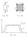
- Fig. 2ashows a micro channel structure having a U configuration 20 provided on a microfluidic disc of the type discussed previously, which is covered by a light absorbing area 22 for the purpose of heating.
- Fig. 2bshows a temperature profile across said light absorbing area along the indicated centerline b-b, when it is illuminated with white light. As can be clearly seen, the temperature profile is bell shaped, which unavoidably will cause uneven heating within the region where the channel structure is provided, thus causing the chemical reactions to run differently in said channel structure at different points.
- the bell shaped temperature profileis "flattened” out to an extent that there will be a more uniform temperature across the part to be heated of the channel structure.
- thiswould require too much surface around the channel structure to be covered by the light-absorbing layer, and since there is a desire to provide a very large number of channel structures close to each other, an enlarged area would occupy too much surface.
- the temperature profilewould still exhibit a more or less clear bell shape, indicating non-uniform temperature over the channel structure defining the reaction volume.
- the heating method and heating element structureprimarily ensures a uniform temperature level in the sense as defined above to be achieved across the surface of a selected area of a substrate where the part(s) to be heated of the micro channel(s) is(are) located.
- the factual variations that may be at hand in the surfacebecomes smaller in any plane inside the selected area.
- the plane referred tois parallel with the surface.
- the flowing airwill have a cooling effect on the surface of the disc, and in fact it is possible to control the rate of cooling very accurately by controlling the speed of rotation, given that the air temperature is known. This effect is utilized in the present invention, and is a key factor for the success of the heating method and system according to the invention.
- plastic materialsin particular transparent plastic materials are non-absorbing with respect to visible light but not to infrared.
- illumination with visible lightwill cause only moderate heating (if any at all), since most of the energy is not absorbed.
- One possibility to convert visible light to heat a defined area or volume (selected area)is to apply a light absorbing material at the location where heating is desired.
- the surfacemay be coated with a mask that reflects the radiation everywhere except for the selected areas.
- the maskmay be physically separated from the substrate but still positioned between the surface of the substrate and the irradiation source.
- the areais given a specific lay-out that changes the temperature profile, from a bell shape to (ideally) an approximate "rectangular" shape, i.e. making the temperature variation uniform across the surface of the selected area or across a plane parallel thereto.
- One methodis by a simple trial end error approach. For non-absorbing materials a pattern of material absorbing the radiation used is placed between the surface of the substrate and the source of radiation. Typical the material is deposited on the substrate. By using an IR video camera, the temperature at the surface can be monitored. Another method for arriving at said lay-out is by employing FEM calculations (Finite Element Method), and will be discussed in further detail below.
- Fig. 3illustrates schematically the change in profile principally achievable by employing the inventive idea.
- the bell shaped profile Aresults with a light absorbing area A having the general extension as shown Fig. 3a , (the profile taken in the cross section indicated by the arrow a), and the "rectangular" profile results when employing a light absorbing region as shown by curve B in Fig. 3 (the profile taken in the cross section indicated by the arrow).
- the most important feature of the temperature profileis that its upper (top) portion is flattened (uniform), thus implying a low variation in temperature across the corresponding part of the selected area.
- the "flanks”, i.e. the side portions of the profilewill always exhibit a slope, but by suitable measures this slope can be controlled to the extent that the profile better will approximate an ideal rectangular shape.
- electromagnetic radiationfor instance light
- a surface of the selected areais covered/coated with a layer absorbing the radiation energy, e.g. light.
- the layermay be a black paint.
- the paintis laid out in a pattern of absorbing and non-absorbing (coated and non-coated) parts (subareas) on the surface of the selected areas.
- non-absorbing partincludes covering with a material reflecting the radiation.
- the layer absorbing the irradiationis typically within the substrate containing the micro channel.
- the distance between the layer absorbing the irradiation used and reactor volumeat most the same as the shortest distance between the reactor volume and the surface of the substrate.
- a relatively high increase in temperaturemeans up to below the boiling point of water, for instance in the interval 90-97°C and/or an increase of 40-50°C.
- the absorbing layermay also located to the the inner wall of the reactor volume.
- the first embodimentalso includes a variant in which the substrate is made of plastic material that can absorb the electromagnetic radiation used.
- a reflective material containing patterns of non-absorbing material including perforationsis placed between the surface of the selected areas and the source of radiation.
- the reflective materialfor instance is coated or imprinted on the surface of the substrate.
- Non-adsorbing patterns, for instance patterns of perforationare selectively aligned with the surfaces of the selected areas.
- This variantmay be less preferred because absorption of irradiation energy will be essentially equal throughout the selected area that may counteract quick cooling.
- absorbing plastic materialis meant a plastic material that can be significantly and quickly heated by the electromagnetic radiation used.
- non-adsorbing plastic materialmeans plastic material that is not significantly heated by the electromagnetic radiation used for heating.
- patternmeans the distribution of both absorbing and non-absorbing parts (subareas) across a layer of the selected area, for instance a surface layer.
- the inventionwill now be illustrated by different patterns of absorbing materials coated on substrates made of non-absorbing plastic material.
- substrates made of absorbing plastic materialsimilar patterns apply but the non-absorbing parts are replaced with a reflective material and the absorbing parts are typically uncovered.
- a micro channel/chamber structurea few examples of which are indicated in Fig. 4a-e .
- This kind of channel/chamber structurescan be provided in a large number, e.g. 400, on a microfluidic disc 40 (schematically shown in Fig. 5a ). All structures need not be identical, but in most cases they will be, for the purpose of carrying out a large number of similar reactions at the same time. If we assume that all channel/chamber structures are identical, and that only one portion (e.g. a reaction chamber or a segment of a channel) of the channel/chamber structure needs to be heated during the operation, it will be convenient to provide the inventive heating element structure, e.g. as in Fig. 3b , as concentric bands of paint 42, 44, as shown in Fig. 5b , or some other kind of absorbing material.
- the heating element structure described aboveis applicable to all channel/chamber structures shown in Fig. 4 .
- a channel/chamber structure 70with a circular chamber with an inlet 71 and an outlet 72 channel.
- a heating element structure as shown in Fig. 7bcan be employed, comprising concentric bands B1, b2 and a center spot c1.
- the temperature profilewill be the same in all cross sections through the center of the micro channel/chamber structure, and look something like the profile of Fig. 7c .
- Fig. 8a-ca similar structure, but applied to a rectangular chamber is shown.
- Fig. 8cshows the temperature profiles C1, C2 in directions c1 and c2 of Fig. 8b , respectively.
- lamps of relatively high poweris used, suitably e.g. 150 W.
- Suitable lampsare of the type used in slide projectors, since they are small and are provided with a reflector that focuses the radiation used.
- the irradiationcan be selected among UV, IR, visible light and other forms of light as long as one accounts for matching the substrate material and the absorbing layer properly.
- the lampgives a desired wave-length band but in addition also wavelengths that cause heat production within the substrate it may be necessary to include the appropriate filter.
- Halogen lampse.g. can be used for selectively give visible light because that typically contains an IR-filter. In order to achieve the best results the light should be focussed onto the substrate corresponding to a limited region on the substrate, e.g.
- One or more lampscould be used in order to enable illumination of one or more regions, e.g. in the event it is desirable to carry out different reactions at different locations on a substrate On a rotating disc it might be desirable to perform heating at different radial locations.
- Illumination of the substratecan be from both sides. If the light absorbing material is deposited on the bottom side, nevertheless the illumination can be on the topside, in which case light is transmitted through the substrate before reaching the light absorbing material. Illumination of the backside with material deposited on the topside is also possible.
- the patternsare applied e.g. by printing of ink comprising conductive particles, e.g. carbon particles mixed with a suitable binding agent, using e.g. screen printing techniques. Patterns functioning in the same way may also be created by the following steps
- the width of the non-coated areascan be larger nearer the periphery than the width of those nearer the center.
- the rotatable disccomprises a base portion having a top and a bottom side, on the topside of which said micro channel structure is provided, and on top of which a cover is provided so as to seal the micro channel structure.
- the heating elementsare preferably provided on the top surface so as to cover the selected area to be heated.
- said light absorbing layercan also, as an alternative, be provided on said bottom side.
- the heating element structurescan be applied to stationary substrates, i.e. chip type devices.
- stationary substratesit will be necessary to use forced convection, e.g. by using fans or the like to supply the necessary cooling.
- the micro channel/chamber structures and heating structurescan be identical.
- flanks of the temperature profileexhibits a certain slope, which has as a consequence that an area surrounding the part of the micro channel structure that is to be heated, will also be heated. This is because the substrate material adjacent the region which is coated will dissipate heat from the area beneath the coating.
- One way of reducing this heat dissipationis to reduce the cross section for heat conduction. This can be done by providing a recess 93 in the substrate 94 on the opposite side of the coating 95 along the periphery of said coating as shown in Fig. 10a . In this way the resistance to heat being conducted away from the coated region will be increased.
- Another way to obtain a similar resultis to provide holes 96 instead of said recess, but along the same line as said recess, as shown in Fig. 10b .
- a system for performing PCRin accordance with the present invention.
- the systemcomprises a control unit CPU for controlling the operation of the system; a rotatable 100 disc comprising a plurality of micro channel/chamber structures 102; a device for supplying heat to the channel/chamber structures (in the example the heat source is a lamp 104, but of course resistive heating as discussed herein is also possible); a reflector 105 for focussing the light onto the disc 100; a motor 106 for rotating said disc 100, the speed of rotation of which can be controlled by the control unit.
- a control unit CPUfor controlling the operation of the system
- a rotatable 100 disccomprising a plurality of micro channel/chamber structures 102
- a device for supplying heat to the channel/chamber structuresin the example the heat source is a lamp 104, but of course resistive heating as discussed herein is also possible
- a reflector 105for focussing the light onto the disc 100
- a motor 106for rotating said disc 100, the
- the discis provided with a mask (see Figs 5b , 6a , 7b , 8b and related disclosure) to create a uniform temperature level across a selected area in which PCR reaction is to be performed, the selected pattern being dependent on the configuration of the channel/chamber system that will be used.
- a channel having a U configuration 120 of the type disclosed in Fig. 12is used (this is essentially the same configuration as that of fig. 2a ).
- Fig. 12only shows a part of the overall channel/chamber structure, namely that part in which the PCR is carried out.
- the reactorcomprises a micro channel laid out as a U turn on the disc, having two legs, the legs having a generally radial extension.
- a first leg 122will constitute an inlet portion
- a second leg 124will constitute an outlet portion.
- a sampleis introduced into the channel system at point 108 near the center of the disc. Then the disc is spun whereby the sample 110 is transferred through the channel system down to the U turn where it will stay (the sample volume is defined by the two level indications L), by virtue of the U acting as a stop for further flow through the channel system.
- the next step in the PCR procedureis to carry out a temperature cycling process, where it is important that the temperature is maintained constant and uniform within the reaction volume. This can be achieved by providing the disc with a mask element such as the one shown in Fig. 6a . Spinning the disc and illuminating with the lamp will then cause the temperature to increase to a desired level determined by the power of the lamp and the speed of rotation.
- the control unitWhen it is desired to change the temperature from say 95°C to 70°C, which is a common temperature jump, the control unit will reduce the power and the speed of the motor. With the system of the invention this temperature jump can be done in 3 seconds.
- One further aspect of the inventionis an instrument comprising a rotatable disc as defined in any of claims 27-29 and a spinner motor with a holder for the disc, said motor enabling spinning speeds that are possible to regulate.
- the spinning of the motorcan be regulated within an interval that typically can be found within 0-20 000 rpm.
- the instrumentationmay also comprise one or more detectors for detecting the result of the process or to monitor part steps of the process, one or more dispensers for introducing samples, reagents, and/or washing liquids into the micro channel structure of the substrate together with means for other operations that are going to be performed within the instrument.
- a micro channel structure having a U configuration in a rotatable polycarbonate discis used.
- the discis prepared by fusing a polycarbonate film over the micro channel structures and painting the bottom side with a black pattern.
- the CDis spun and the black pattern is exposed to visible light from three150 W halogen lamps.
- the power of the lampsis varied using computer control (software LabView).
- the surface temperatureis measured using an infrared camera.
- a PCR mixis designed to generate a 160 bp product, the composition being given below.
- the program for thermocyclingis as follows: 95 ⁇ °C , 7 ⁇ s ; 70 ⁇ °C , 15 ⁇ s x 20 or 25 cycles
- Stop solutionFormamide containing blue dextran and 2 ⁇ l each of 100 bp and 200 bp size standards per 100 ⁇ l stop solution - ALFexpress reagents.
- Positive controlsare run by thermocycling 1 or 5 ⁇ l of the mix in 200 ⁇ l microreaction tubes in a Perkin Elmer 9600 Thermal cycler as follows:
- the Cy5-labelld PCR productsare analyzed by separation on ReproGel High resolution in ALFexpress and analyzed using Fragment Analyzer 2.02.
- Fig. 13the result of a PCR run performed in a PCR reactor according to the invention is shown. As can be clearly seen, a peak at 160 bp indicates that the reaction has been taking place, thus demonstrating the utility of the invention.
Landscapes
- Chemical & Material Sciences (AREA)
- Health & Medical Sciences (AREA)
- Clinical Laboratory Science (AREA)
- Chemical Kinetics & Catalysis (AREA)
- Biochemistry (AREA)
- Molecular Biology (AREA)
- General Health & Medical Sciences (AREA)
- Life Sciences & Earth Sciences (AREA)
- Physical Or Chemical Processes And Apparatus (AREA)
- Automatic Analysis And Handling Materials Therefor (AREA)
- Apparatus Associated With Microorganisms And Enzymes (AREA)
- Inorganic Insulating Materials (AREA)
- Gripping On Spindles (AREA)
Abstract
Description
- The present invention relates to a device for the controlled thermal cycling of reactions, in particular in small channels that are present within a substrate. In particular the invention relates to a micro channel PCR reactor.
- There is a trend in the chemical and biochemical sciences towards miniaturization of systems for performing analytical tests and for carrying out synthetic reactions, where large numbers of reactions must be performed. For example in screening for new drugs as many as 100000 different compounds need to be tested for specificity by reacting with suitable reagents.
- Another field is polynucleotide amplification, which has become a powerful tool in biochemical research and analysis, and the techniques therefor have been developed for numerous applications. One important development is the miniaturization of devices for this purpose, in order to be able to handle extremely small quantities of samples, and also in order to be able to carry out a large number of reactions simultaneously in a compact apparatus.
- In most systems for the purposes indicated above (and others not mentioned) there would commonly be a need for heating the reagents in some stage of the procedure for carrying out the necessary reactions. Even more importantly there is also a need for maintaining the reaction temperature at a constant level during a desired period of time, i.e. to avoid variations in temperature across the channel part containing the reagents that have been heated.
- Furthermore, in these miniaturized systems the temperature of the wall confining the sample will essentially determine the temperature of the sample. Thus, if the material constituting the wall leads away heat, there will be a temperature drop close to the wall, and a variation throughout the sample occurs.
- There is also a problem with evaporation when heating small aliquots of liquids within micro channel structures. This problem can be solved by providing heating means in the form of a surface layer that is capable of absorbing light energy for transport into a selected area. See
WO 0146465 Fig. 7 and related disclosure). Conveniently white light is used, but for special purposes, monochromatic light (e.g. laser) can also be used. The layer can be a coating of a light-absorbing layer, e.g, a. black paint, which converts the influx of light to heat. - An alternative solution to the evaporation problem has been to carry out the steps involving elevated temperature (heating steps) within closed reaction volumes. This has required solving problems related the large pressure increase that typically is at hand when heating liquid aliquots without venting. If the process concerned is integrated into a sequence of reactions there is a demand for smart valving solutions.
- In many of the prior art devices the substrate material has had a fairly high thermal conductivity which has permitted heating by ambient air or by separate heating elements in close association with the inner wall of the channel containing a liquid to be heated. Cooling has typically utilized ambient air. Recently it has become popular to manufacture micro channel structures in plastic material that typically has a low thermal conductivity. Due to the poor thermal conductivity, unfavorable temperature gradients may easily be formed within the selected area when this latter type of materials is used. These gradients may occur across the surface and downwards into the substrate material. The variation in temperature may be as high as 10°C or more between the center of the area or region and its peripheral portions. If the light absorbing area is too small this variation will be reflected in the temperature profile within a selected area and also within the heated liquid aliquot. For many chemical and biochemical reactions such lack of uniformity can be detrimental to the result, and indeed render the reaction difficult to carry out with an accurate result.
- Although the heating means according to
WO 0146465 - Microfluidic platforms that can be rotated comprising heating elements have been described in
WO 0078455 EP 1 016 864WO 9853311 - In view of the shortcomings of prior art systems, it would be desirable to have access to a device for performing thermal cycling, and in particular PCR (Polymerase Chain Reaction) on small sample volumes. The objects of the invention are to provide a method and a device for temperature cycling of a liquid aliquot in a capillary of the dimensions given below, while minimizing the problems discussed above concerning uncontrolled evaporation and/or increase in pressure and/or to accomplish temperature levels that are at a constant level throughout the reaction volume during steps in which the reaction mixture is maintained at an elevated temperature (heating step). The capillary is preferably a part of a microfluidic device as defined below.
- Such a device is provided according to the present invention and is defined in any of claims 1-15 and 19.
- In the context of the invention the term "selected area" means the selected surface area to be heated plus the underlying part of the substrate containing the reactor volume of one or more micro channels if not otherwise being clear from the particular context. The selected area contains substantially no other essential parts of the micro channels. The term "surface" will refer to the surface to be heated, e.g. the surface collecting the heating irradiation, if not otherwise indicated.
- By the terms "heating structure", "heating element structure" and "heating element" are meant a structure which is present in or on a selected area, or between the substrate and a radiation source, and which defines a pattern which (a) covers a selected area and (b) can be selectively heated by electromagnetic radiation or electricity, such as white or visible light or only IR, or by direct heating such as electricity. In this context the term "pattern" means (1) a continuous layer, or (2) a patterned layer comprising one or more distinct parts that are heated and one or more distinct parts that are not heated. (b) excludes that the pattern consists of only the part that is heated.
- With the device according to the invention it is possible to carry out reactions such as DNA amplification e.g. by PCR in small volumes, which is advantageous in many respects. I.a. the reaction time can be reduced, very many samples can be processed at the same time on a compact device, and very minute volumes of sample can be handled.
- By employing micro channels in the form of a U configuration to define the reactor volume according to an embodiment, another advantage is achieved, namely, it becomes possible to transfer the product of the PCR to further processing steps downstream of the reactor. This has not been possible in the known systems, where the PCR chamber has been the final processing step.
- The terms "U-configuration" and "U-shaped" include shapes in which the channel structure comprises a downward bent with two arms directed more or less upward, for instance Y-shaped structures. If the channel structure is placed on a rotatable disc the downward bent is directed outward and the two upwardly directed arms more or less inwards towards the center of the disc. In case of Y-shaped structures, the downward arm has a valve function that is closed while thermal cycling is carried out on the liquid aliquot present in the downward bent.
- When the thermal cycling is finalized the reaction mixture/reaction product can be transferred further downstream into the channel structure. When the cycling space is part of a U-configuration the transfer can be via one of the upward arms, or via the downward arm if the configuration is Y-shaped. In the first case the reaction product is displaced by a second liquid aliquots and in the second case by overcoming the valve function in lower arm of the Y. If the channel structure is placed on rotatable disc the driving force can be applied as described in
WO 01/46465 - The same advantage is obtained if, as in a further embodiment, the channel structure comprises a straight channel, but is provided with a valve device on the downstream side.
- By leaving the upward arms in communication with ambient air and arrange for proper cooling in the arms the problem of undesired evaporation and over pressure will be overcome.
- The invention will now be described in detail with reference to the attached drawings.
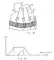
Fig. 1a-d illustrates a prior art microfluidic disc;Fig. 2a-b illustrates a prior art device with (a) a heating structure and (b) a temperature profile across the selected area during heating;Fig. 3a-b illustrates (a) a prior art surface temperature profile and (b) a desired surface temperature profile according to the invention, and a typical temperature profile between the opposing surfaces of a selected area made of plastic material;Fig. 4a-e exemplifies various micro channel structures to which the invention is applicable;Fig. 5a-b illustrates a microfluidic disc having a heating element structure,;Fig. 6a-b illustrates another type of heating element structure and the obtainable temperature profile;Fig 7a-c illustrates still another embodiment of a reactor system and a heating element structure therefor, and the obtainable temperature profile;Fig. 8a-c is a further embodiment implemented for another geometry;Fig. 9a-b is embodiments of a resistive heating element structure;Fig. 10a-b illustrates means for controlling the flanks of the temperature profile;Fig. 11 shows a reactor system according to the invention for performing PCR;Fig. 12 is a detail view showing the part of a U configuration of a micro channel structure where the PCR is to be performed; andFig. 13 illustrates the result of a PCR performed according to the invention.- For the purpose of this application the term "micro channel structure" as used herein shall be taken to mean one or more channels, optionally connecting to one or more enlarged portions forming chambers having a larger width than the channels themselves. The micro channel structure is provided beneath the surface of a flat substrate, e.g. a disc member.
- The terms "micro format", "micro channel" etc contemplate that the micro channel structure comprises one or more chambers/cavities and/or channels that have a depth and/or a width that is ≤ 103 µm, preferably ≤ 102 µm. The volumes of micro cavities/micro chambers are typically ≤ 1000 nl, such as ≤ 500 nl or ≤100 nl or ≤ 50 nl. Chambers/cavities directly connected to inlet ports may be considerably larger, e.g. when they are intended for application of sample and/or washing liquids.
- In the preferred variants volumes of the liquid aliquots used are very small, e.g. in the nanoliter range or smaller (≤ 1000 nl). This means that the spaces in which reactions, detections etc are going to take place often becomes more or less geometrically indistinguishable from the surrounding parts of a micro channel.
- A reactor volume is the part of a micro channel in which the liquid aliquot to be heated is retained during a reaction at an elevated temperature. Typically reaction sequences requiring thermal cycling or otherwise elevated temperature take place in the reaction volume.
- The disc preferably is rotatable by which is meant that it has an axis of symmetry (Cn) perpendicular to the disc surface. n is an
integer - By the expressions "essentially uniform temperature profile" and "constant temperature" are meant that temperature variations within a selected area of the substrate are within such limits that a desired temperature sensitive reaction can be carried out without undue disturbances, and that a reproducible result is achievable. This typically means that within the reaction volume, the temperature varies at most 50 %, such as at most 25 % or at most 10 % or 5 % of the maximum temperature difference between the opposing surfaces of the selected area comprising the heated liquid aliquot. These permitted variations apply across a plane that is parallel to the surface and/or along the depth of the micro channel. The acceptable temperature variation may vary from one kind of reaction to another, although it is believed that the acceptable variation normally is within 10°C, such as within 5°C or within 1°C.
- The present invention suitably is implemented with micro channel structures for a rotating microfluidic disc of the kind, but not limited thereto, disclosed in
WO 0146465 Fig. 1 in the present application, there is shown a device according to said application. However, it is to be noted that this is only an example and that the present invention is not limited to use of such micro channel structures. - The micro channel structures K7-
K 12 according to this known device, shown infigures 1 a-d , are arranged radially on a microfluidic disc D. Suitably the microfluidic disc is of a one- or two-piece moulded construction and is formed of an optionally transparent plastic or polymeric material by means of separate mouldings which are assembled together (e.g. by heating) to provide a closed unit with openings at defined positions to allow loading of the device with liquids and removal of liquid samples. See for instanceWO 0154810 WO 0147637 WO 0056808 - The microchannels may be formed by micro-machining methods in which the micro-channels are micro-machined into the surface of the disc, and a cover plate, for example, a plastic film is adhered to the surface so as to close the channels. Another method that is possible is injection molding. The typical microfluidic disc D has a thickness which is much less than its diameter and is intended to be rotated around a central hole so that centrifugal force causes fluid arranged in the microchannels in the disc to flow towards the outer periphery of the disc. In the embodiment of the present invention shown in
figures 1a-1d , the microchannels start from a common, annularinner application channel 1 and end in common, annularouter waste channel 2, substantially concentric withchannel 1. It is also possible to have individual application channels (waste channels for each microchannel or a group of microchannels). Each inlet opening 3 of the microchannel structures K7-K 12 may be used as an application area for reagents and samples. Each microchannel structure K7-K12 is provided with awaste chamber 4 that opens into theouter waste channel 2. Each microchannel K7-K12 forms a U-shapedvolume defining configuration 7 and aU-shaped chamber 10 between itsinlet opening 3 and thewaste chamber 4. The normal desired flow direction is from the inlet opening 33 to thewaste chamber 4 via the U-shaped volume-definingconfiguration 7 and theU-shaped chamber 10. Flow can be driven by capillary action, pressure, vacuum and centrifugal force, i.e. by spinning the disc. As explained later, hydrophobic breaks can also be used to control the flow. Radially extending waste channels 5, which directly connect the annularinner channel 1 with the annularouter waste channel 2, in order to remove an excess fluid added to theinner channel 1, are also shown. - Thus, liquid can flow from the
inlet opening 3 via anentrance port 6 into avolume defining configuration 7 and from there into a first arm of aU-shaped chamber 10. The volume-definingconfiguration 7 is connected to a waste outlet for removing excess liquid, for example, radially extendingwaste channel 8 whichwaste channel 8 is preferably connected to the annularouter waste channel 2. Thewaste channel 8 preferably has avent 9 that opens into open air via the top surface of the disk.Vent 9 is situated at the part of thewaste channel 8 that is closest to the centre of the disc and prevents fluid in thewaste channel 8 from being sucked back into the volume-definingconfiguration 7. - The
chamber 10 has a first,inlet arm 10a connected at its lower end to abase 10c, which is also connected to the lower end of a second,outlet arm 10b. Thechamber 10 may have sections I, II, III, IV which have different depths, for example each section could be shallower than the preceding section in the direction towards the outlet end, or alternatively sections I and III could be shallower than sections II and IV, or vice versa. A restrictedwaste outlet 11, i.e. a narrow waste channel is provided between thechamber 10 and thewaste chamber 4. This makes the resistance to liquid flow through thechamber 10 greater than the resistance to liquid flow through the path that goes through volume-definingconfiguration 7 andwaste channel 8. - By introducing a well defined volume of sample that will just about fill one U shaped volume of this configuration, it will be possible to confine this sample within the portion of the micro channel structure that is defined by said U, by spinning the disc, and thus impose a simulated gravity. If the spinning speed is sufficient, the force imposed will counteract the tendency of the sample to evaporate if heated. If heating is applied locally and the material of the disc has a low thermal conductivity, for instance plastics, a steep decreasing temperature gradient will form between the heated and non-heated area. The upper part of the arms will act as a cooler and assist in counteracting evaporation. The need for securing evaporation losses by closing the system can be avoided. Thus, in fact the U shaped volume will be an effective reaction chamber for the purpose of thermal cycling, e.g. for performing polynucleotide amplification by thermal cycling.
- However, it is equally possible to use a micro channel structure without the above discussed U-configuration, namely by employing a straight, radially extending channel, but provided with a stop valve at the end closest to the disc circumference. A valve suitable for this purpose is disclosed in
WO 0102737 - Another way of providing a valve or stop for preventing the sample from evaporating and moving in the channels during temperature cycling or simple heating, is to provide a minute amount of metal having low melting temperature, such as Woods metal or similar types of metal, having melting points in the relevant region. Another possible type of material is wax. It should of course not melt at the temperature prevailing during the reaction, but at a slightly higher level, say 100°C, if the reaction temperature is 95°C. Such metals are well known to the skilled man, and are easily adapted to the situation at hand without undue experimentation.
- Also mechanical valves can be used in the variants mentioned above.
- However, as indicated above, it is essential that a uniform temperature level can be maintained locally in the entire reaction volume preferably with a steep temperature gradient to the non-heated parts of the microfluidic substrate. Such controlled heating is conveniently performed by a contact heating system and method disclosed herein, embodiments of which will now be described in detail below. The heating system referred to in this paragraph may be based on contact heating or non-contact heating.
Fig. 2a shows a micro channel structure having aU configuration 20 provided on a microfluidic disc of the type discussed previously, which is covered by alight absorbing area 22 for the purpose of heating.Fig. 2b shows a temperature profile across said light absorbing area along the indicated centerline b-b, when it is illuminated with white light. As can be clearly seen, the temperature profile is bell shaped, which unavoidably will cause uneven heating within the region where the channel structure is provided, thus causing the chemical reactions to run differently in said channel structure at different points.- It would be possible to enlarge the area such that its periphery is located sufficiently remote from the channel structure that the bell shaped temperature profile is "flattened" out to an extent that there will be a more uniform temperature across the part to be heated of the channel structure. However, in the first place this would require too much surface around the channel structure to be covered by the light-absorbing layer, and since there is a desire to provide a very large number of channel structures close to each other, an enlarged area would occupy too much surface. Secondly, even if a very large area is provided the temperature profile would still exhibit a more or less clear bell shape, indicating non-uniform temperature over the channel structure defining the reaction volume.
- In essence, it all comes down to enabling heating of a local area of a substrate containing a micro channel/chamber structure, in a controlled way, so as to achieve a uniform heating across the volume containing the liquid aliquot to be heated. This should be achieved at the same time as surrounding elements should be as little affected as possible by the heating, i.e. preferably, areas immediately adjacent the heated region, e.g. another part of the micro channel structure, should not be heated at all, in the ideal situation. It is of course desirable that the temperature is equal throughout the entire volume. In the case of the present invention implemented in small micro channels and heating at the surface closest to the microchannel, the heating method and heating element structure, primarily ensures a uniform temperature level in the sense as defined above to be achieved across the surface of a selected area of a substrate where the part(s) to be heated of the micro channel(s) is(are) located. The factual variations that may be at hand in the surface becomes smaller in any plane inside the selected area. The plane referred to is parallel with the surface. However, there will be a relatively large temperature drop through the thickness of the disc. This drop typically is of the order of 10°C. In spite of this, because the channel dimensions are so small, only about 1/10 of the thickness of the substrate, the temperature drop over the channel in this direction will be only about 1°C, which is acceptable for all practical purposes. This is illustrated in
Fig. 3c . This relatively large temperature drop along the thickness of the substrate will assist in an efficient and rapid cooling of the heated liquid aliquot after a heating step. This becomes particularly important if the process performed comprises repetitive heating and cooling (thermal cycling) of the liquid aliquot. Cooling will be assisted by spinning the disc. - When a disc is rotated, the frictional forces will drag air at the surface of the disc. Thus, the air near the disc will rotate in the same direction as the disc. The rotation of the air will result in centrifugal forces that will cause the air to flow radially.
- The flowing air will have a cooling effect on the surface of the disc, and in fact it is possible to control the rate of cooling very accurately by controlling the speed of rotation, given that the air temperature is known. This effect is utilized in the present invention, and is a key factor for the success of the heating method and system according to the invention.
- It would be possible to obtain the same effect if one uses controlled air flow from a fan or the like, where the cooling effect can be varied by varying the speed of the fan. This method could be used for stationary systems where the regions, e.g. comprising micro channels to be cooled, to be cooled are made in e.g. a flat substrate which is non-rotary.
- Most plastic materials, in particular transparent plastic materials are non-absorbing with respect to visible light but not to infrared. For microfluidic discs, which are normally made of transparent polymeric materials, illumination with visible light will cause only moderate heating (if any at all), since most of the energy is not absorbed. One possibility to convert visible light to heat a defined area or volume (selected area) is to apply a light absorbing material at the location where heating is desired.
- Thus, in order to transform light to heat light-absorbing material must be provided at the position where heating is desired. This can conveniently be achieved by covering the position or region with e.g. black color by printing or painting. Between the various spots of light absorbing material there may be a material reflecting the irradiation used. An alternative for the same kind of substrates is to cover one of the substrate surfaces with a light absorbing material and illuminating this surface through a mask only permitting light to pass through holes in the mask that are aligned with the selected areas.
- For substrates made in plastic material that absorbs the radiation used, the surface may be coated with a mask that reflects the radiation everywhere except for the selected areas. Alternative the mask may be physically separated from the substrate but still positioned between the surface of the substrate and the irradiation source.
- Therefore, the area is given a specific lay-out that changes the temperature profile, from a bell shape to (ideally) an approximate "rectangular" shape, i.e. making the temperature variation uniform across the surface of the selected area or across a plane parallel thereto. One method is by a simple trial end error approach. For non-absorbing materials a pattern of material absorbing the radiation used is placed between the surface of the substrate and the source of radiation. Typical the material is deposited on the substrate. By using an IR video camera, the temperature at the surface can be monitored. Another method for arriving at said lay-out is by employing FEM calculations (Finite Element Method), and will be discussed in further detail below.
Fig. 3 illustrates schematically the change in profile principally achievable by employing the inventive idea. The bell shaped profile A results with a light absorbing area A having the general extension as shownFig. 3a , (the profile taken in the cross section indicated by the arrow a), and the "rectangular" profile results when employing a light absorbing region as shown by curve B inFig. 3 (the profile taken in the cross section indicated by the arrow). - The most important feature of the temperature profile is that its upper (top) portion is flattened (uniform), thus implying a low variation in temperature across the corresponding part of the selected area. The "flanks", i.e. the side portions of the profile will always exhibit a slope, but by suitable measures this slope can be controlled to the extent that the profile better will approximate an ideal rectangular shape.
- Now various embodiments of the heating system and different aspects thereof will be described with reference to the drawings.
- In a first embodiment of the invention, electromagnetic radiation, for instance light, is used for heating a liquid present in a selected area of a substrate made of a plastic material not absorbing the radiation used for heating. In this case a surface of the selected area is covered/coated with a layer absorbing the radiation energy, e.g. light. As outlined in this specification the kind of radiation, plastic material and absorbing layer must match each other. The layer may be a black paint. The paint is laid out in a pattern of absorbing and non-absorbing (coated and non-coated) parts (subareas) on the surface of the selected areas. The term "non-absorbing part" includes covering with a material reflecting the radiation. In other variants of this embodiment, the layer absorbing the irradiation is typically within the substrate containing the micro channel. In the case quick and/or relatively high increase in temperature is needed, the distance between the layer absorbing the irradiation used and reactor volume at most the same as the shortest distance between the reactor volume and the surface of the substrate. A relatively high increase in temperature means up to below the boiling point of water, for instance in the interval 90-97°C and/or an increase of 40-50°C. The absorbing layer may also located to the the inner wall of the reactor volume.
- The first embodiment also includes a variant in which the substrate is made of plastic material that can absorb the electromagnetic radiation used. In this case a reflective material containing patterns of non-absorbing material including perforations is placed between the surface of the selected areas and the source of radiation. This includes that the reflective material for instance is coated or imprinted on the surface of the substrate. Non-adsorbing patterns, for instance patterns of perforation, are selectively aligned with the surfaces of the selected areas. This variant may be less preferred because absorption of irradiation energy will be essentially equal throughout the selected area that may counteract quick cooling.
- By the term "absorbing plastic material" is meant a plastic material that can be significantly and quickly heated by the electromagnetic radiation used. The term "non-adsorbing plastic material" means plastic material that is not significantly heated by the electromagnetic radiation used for heating.
- The term "pattern" above means the distribution of both absorbing and non-absorbing parts (subareas) across a layer of the selected area, for instance a surface layer. The term excludes variants where the pattern only comprises one absorbing part covering completely the surface of the selected area.
- The invention will now be illustrated by different patterns of absorbing materials coated on substrates made of non-absorbing plastic material. For substrates made of absorbing plastic material, similar patterns apply but the non-absorbing parts are replaced with a reflective material and the absorbing parts are typically uncovered.
- As a first example let us consider a micro channel/chamber structure, a few examples of which are indicated in
Fig. 4a-e . This kind of channel/chamber structures can be provided in a large number, e.g. 400, on a microfluidic disc 40 (schematically shown inFig. 5a ). All structures need not be identical, but in most cases they will be, for the purpose of carrying out a large number of similar reactions at the same time. If we assume that all channel/chamber structures are identical, and that only one portion (e.g. a reaction chamber or a segment of a channel) of the channel/chamber structure needs to be heated during the operation, it will be convenient to provide the inventive heating element structure, e.g. as inFig. 3b , as concentric bands ofpaint Fig. 5b , or some other kind of absorbing material. - The provision of this basic band configuration is not an optimal solution, however, since the temperature profile still exhibits a slight fluctuation over the area to be heated. In a preferred embodiment therefore, there is provided several narrow bands b1, b2 of light absorbing material (paint) between the larger bands B1, B2, as schematically shown in
Fig. 6a , which shows a broken away view of adisc 40 having a plurality ofchannel structures Fig. 6b the corresponding temperature profile achievable with this band configuration is shown. In this example it is the part of the micro channel structure delimited by the square A (Fig 6a ) that it is desired to heat in a controlled manner. - The heating element structure described above is applicable to all channel/chamber structures shown in
Fig. 4 . - However, for certain applications it can be desirable to provide even more localized heating, e.g. of a circular or rectangular/square area. This would especially be required if adjacent or surrounding areas must not be heated at all. The embodiment with concentric bands of paint will result in heating also of the areas between the radially extending micro channel/chamber structure.
- In
Fig. 7a there is shown a channel/chamber structure 70 with a circular chamber with aninlet 71 and anoutlet 72 channel. If it is important to avoid heating of the disc area surrounding the chamber, a heating element structure as shown inFig. 7b can be employed, comprising concentric bands B1, b2 and a center spot c1. In this case the temperature profile will be the same in all cross sections through the center of the micro channel/chamber structure, and look something like the profile ofFig. 7c . - In
Fig. 8a-c a similar structure, but applied to a rectangular chamber is shown.Fig. 8c shows the temperature profiles C1, C2 in directions c1 and c2 ofFig. 8b , respectively. - For the illumination, lamps of relatively high power is used, suitably e.g. 150 W. Suitable lamps are of the type used in slide projectors, since they are small and are provided with a reflector that focuses the radiation used. The irradiation can be selected among UV, IR, visible light and other forms of light as long as one accounts for matching the substrate material and the absorbing layer properly. In case the lamp gives a desired wave-length band but in addition also wavelengths that cause heat production within the substrate it may be necessary to include the appropriate filter. Halogen lamps, e.g. can be used for selectively give visible light because that typically contains an IR-filter. In order to achieve the best results the light should be focussed onto the substrate corresponding to a limited region on the substrate, e.g. about 2 cm in diameter, although of course the size may be varied in relation to the power of the lamp etc. One or more lamps could be used in order to enable illumination of one or more regions, e.g. in the event it is desirable to carry out different reactions at different locations on a substrate On a rotating disc it might be desirable to perform heating at different radial locations. Illumination of the substrate can be from both sides. If the light absorbing material is deposited on the bottom side, nevertheless the illumination can be on the topside, in which case light is transmitted through the substrate before reaching the light absorbing material. Illumination of the backside with material deposited on the topside is also possible.
- In view of the spinning speed of a rotating microfluidic disc being as high as of the order of 1000 rpm, the pulsing effect obtained in this way will not be noticeable and the heating can for all practical purposes be considered as continuous.
- The above described embodiments have employed light absorbing material to provide the heating elements, but it is possible to employ any heating element structure in a suitable pattern that is capable of generating heat. Thus, it is also contemplated to provide areas of a resistive material 91, 92 in the same general lay-outs as shown in
Fig. 7-8 . Examples thereof applied to the same channel structures as those inFigs. 7-8 are shown inFig. 9a-b . - The patterns are applied e.g. by printing of ink comprising conductive particles, e.g. carbon particles mixed with a suitable binding agent, using e.g. screen printing techniques. Patterns functioning in the same way may also be created by the following steps
- (a) covering the surface of a substrate made of non-absorbing material with absorbing material and placing a reflective mask which contains patterns of holes or of non-absorbing material between the surface of the substrate and the source of the radiation with the individual patterns being aligned with the surfaces of the selected areas.
- Another aspect that should be considered for the performance is the effect of cooling from the air flowing on the disc when it is rotated. Let us consider the configuration shown in
Fig. 6 again. By the spinning action air will be forced radially outwards over the surface of the disc and will thereby cool the surface by absorbing some heat, such that the air is also heated. Thus, the air temperature will be higher towards the periphery of the disc, and the non-coated area between the bands of light absorbing material nearest the periphery will therefore not be as efficient in terms of decreasing the temperature as the non-coated/non-adsorbing area between the bands of light absorbing material closer the center. - In order to compensate for this phenomenon, the width of the non-coated areas can be larger nearer the periphery than the width of those nearer the center.
- Normally the rotatable disc comprises a base portion having a top and a bottom side, on the topside of which said micro channel structure is provided, and on top of which a cover is provided so as to seal the micro channel structure. The heating elements (layer absorbing radiation energy) are preferably provided on the top surface so as to cover the selected area to be heated. However, said light absorbing layer can also, as an alternative, be provided on said bottom side.
- In still another embodiment the heating element structures can be applied to stationary substrates, i.e. chip type devices. In case of stationary substrates it will be necessary to use forced convection, e.g. by using fans or the like to supply the necessary cooling. In all other respects the micro channel/chamber structures and heating structures can be identical.
- As mentioned above the flanks of the temperature profile exhibits a certain slope, which has as a consequence that an area surrounding the part of the micro channel structure that is to be heated, will also be heated. This is because the substrate material adjacent the region which is coated will dissipate heat from the area beneath the coating. One way of reducing this heat dissipation is to reduce the cross section for heat conduction. This can be done by providing a
recess 93 in thesubstrate 94 on the opposite side of thecoating 95 along the periphery of said coating as shown inFig. 10a . In this way the resistance to heat being conducted away from the coated region will be increased. Another way to obtain a similar result is to provideholes 96 instead of said recess, but along the same line as said recess, as shown inFig. 10b . - A particularly suitable application of the heating system in combination with the micro channel structures disclosed herein previously is for performing PCR (Polymerase Chain Reaction), an example of which will be given below with reference to
Fig. 11 . - Thus, in
Fig. 11 there is illustrated a system for performing PCR in accordance with the present invention. The system comprises a control unit CPU for controlling the operation of the system; a rotatable 100 disc comprising a plurality of micro channel/chamber structures 102; a device for supplying heat to the channel/chamber structures (in the example the heat source is alamp 104, but of course resistive heating as discussed herein is also possible); areflector 105 for focussing the light onto thedisc 100; amotor 106 for rotating saiddisc 100, the speed of rotation of which can be controlled by the control unit. - The disc is provided with a mask (see
Figs 5b ,6a ,7b ,8b and related disclosure) to create a uniform temperature level across a selected area in which PCR reaction is to be performed, the selected pattern being dependent on the configuration of the channel/chamber system that will be used. - In a preferred embodiment of a PCR reactor according to the invention, a channel having a
U configuration 120 of the type disclosed inFig. 12 is used (this is essentially the same configuration as that offig. 2a ).Fig. 12 only shows a part of the overall channel/chamber structure, namely that part in which the PCR is carried out. Thus, the reactor comprises a micro channel laid out as a U turn on the disc, having two legs, the legs having a generally radial extension. Afirst leg 122 will constitute an inlet portion, and asecond leg 124 will constitute an outlet portion. - When it is desired to do a PCR, a sample is introduced into the channel system at
point 108 near the center of the disc. Then the disc is spun whereby thesample 110 is transferred through the channel system down to the U turn where it will stay (the sample volume is defined by the two level indications L), by virtue of the U acting as a stop for further flow through the channel system. - The next step in the PCR procedure is to carry out a temperature cycling process, where it is important that the temperature is maintained constant and uniform within the reaction volume. This can be achieved by providing the disc with a mask element such as the one shown in
Fig. 6a . Spinning the disc and illuminating with the lamp will then cause the temperature to increase to a desired level determined by the power of the lamp and the speed of rotation. - When it is desired to change the temperature from say 95°C to 70°C, which is a common temperature jump, the control unit will reduce the power and the speed of the motor. With the system of the invention this temperature jump can be done in 3 seconds.
- One further aspect of the invention is an instrument comprising a rotatable disc as defined in any of claims 27-29 and a spinner motor with a holder for the disc, said motor enabling spinning speeds that are possible to regulate. Typically the spinning of the motor can be regulated within an interval that typically can be found within 0-20 000 rpm. The instrumentation may also comprise one or more detectors for detecting the result of the process or to monitor part steps of the process, one or more dispensers for introducing samples, reagents, and/or washing liquids into the micro channel structure of the substrate together with means for other operations that are going to be performed within the instrument.
- The invention will now be illustrated by way of an example.
- A micro channel structure having a U configuration in a rotatable polycarbonate disc is used. The disc is prepared by fusing a polycarbonate film over the micro channel structures and painting the bottom side with a black pattern. The CD is spun and the black pattern is exposed to visible light from three150 W halogen lamps. The power of the lamps is varied using computer control (software LabView). The surface temperature is measured using an infrared camera.
- A PCR mix is designed to generate a 160 bp product, the composition being given below.
Component Final conc./amount PCR buffer (AP Biotech) x1 Ficoll 400 (AP Biotech) 10% Cresol Red 0.2 mg/ml dNTPs (AP Biotech) 200 µM Primers (RIT 29 and M13 Universal)* 15 pmol AmpliTaq (PEBiosystems) 1U pUC19 Template (AP Biotech) 250 ng Total volume 50 µl *RIT 29: 5'-Biotin-GCT TCC GGC TCG TAT GTT GTG TG
M13 Universal: 5'-Cy5-CGA CGT TGT AAA ACG ACG GCC AGT
- After cycling the contents is ejected by suction and diluted with 5 µl Stop solution (Formamide containing blue dextran and 2 µl each of 100 bp and 200 bp size standards per 100 µl stop solution - ALFexpress reagents).
- Positive controls are run by thermocycling 1 or 5 µl of the mix in 200 µl microreaction tubes in a Perkin Elmer 9600 Thermal cycler as follows:
- (AUTO profile, 2 step; 95°C, 30 s; 70°C, 120 s) x 30
- Hold profile; 4°C -> ∞
- The Cy5-labelld PCR products are analyzed by separation on ReproGel High resolution in ALFexpress and analyzed using Fragment Analyzer 2.02.
- In
Fig. 13 the result of a PCR run performed in a PCR reactor according to the invention is shown. As can be clearly seen, a peak at 160 bp indicates that the reaction has been taking place, thus demonstrating the utility of the invention. - Although the invention has been described with reference to the drawings and an example, it should not be regarded as limited to the shown embodiments, the scope of the invention being defined by the appended claims.

Claims (19)
- A micro channel reactor apparatus suitable for performing temperature cycling, comprising a substrate having at least one micro channel structure, the micro channel structure comprising one or more micro channels wherein(a) at least a portion of at least one of said micro channels constitutes a reaction volume, for performing said temperature cycling; and(b) there is provided a heating structure (42, 44; b1, b2, B1, B2; B1, b2, c1) definingi) a selected area on said substrate, including said reaction volume in which said temperature cycling is to be performed; andii) a temperature profile in said reaction volume such that an essentially uniform temperature is obtainable and maintained in said reaction volume, said heating structure comprising a material capable of transferring heat into said selected area when suitably energized, said materialcharacterized by being laid in a pattern that causes heating and cooling to balance each other so as to create said essentially uniform temperature in said reaction volume.
- The microchannel reactor apparatus of claim 1 wherein said heating structure defines a continuous layer covering said selected area.
- The reactor apparatus as claimed in any of claims 1-2 wherein said heating structure comprises a material provided on said substrate..
- The reactor apparatus as claimed in any of claims 1-4 wherein the micro channel structure comprises at least one channel exhibiting a U turn, defining said reaction volume.
- The reactor apparatus as claimed in any of claims 1-4 wherein the reaction volume is defined in a straight channel provided with a valve to prevent a sample from being moved in the channel beyond the reaction volume, said valve comprising a plug of a material that is capable of changing its volume in response to some external stimulus, such as light, heat, radiation, magnetism.
- The reactor apparatus as claimed in claim 5 wherein said material being selected from polymers, waxes and metals having low melting temperature.
- The reactor apparatus as claimed in any of claims 3-6 wherein the material being capable of transferring heat into said selected area when suitably energized, comprises a pattern of areas of a material capable of absorbing electromagnetic energy, provided so as to cover said reaction volume.
- The reactor apparatus as claimed in claim 7 wherein the material capable of absorbing electromagnetic energy is capable of absorbing light.
- The reactor apparatus as claimed in any of claims 1-8 wherein said heating structure comprises a separate member disposed so as to mask electromagnetic radiation directed towards the surface of the substrate, and having openings defining said pattern, and wherein the material being capable of transferring heat into said selected area when suitably energized, is provided as a continuous layer covering said reaction volume.
- The reactor apparatus as claimed in any of claims 3-9 wherein the material being capable of transferring heat into said selected area when suitably energized, comprises a pattern of areas of a resistive material capable of generating heat when an electric current is passed therethrough, and provided so as to cover said reaction volume.
- The reactor apparatus as claimed in any preceding claim wherein the portion constituting said reaction volume has an inlet end and an outlet end, and said reaction volume has the same cross section as the portions of said micro channel connecting to said reaction volume at both the inlet and the outlet end thereof.
- The reactor apparatus as claimed in any preceding claim, wherein the substrate is a rotatable disc.
- The reactor apparatus as claimed in any of claims 1-5 or 7-12 wherein the substrate is a stationary, non-rotary member.
- A system for performing temperature cycling, comprising(a) a reactor apparatus as claimed in claim 1;(b) a motor coupled to the reactor apparatus to enable rotation of the apparatus;(c) a source of energy for heating said reactor apparatus;(d) a control unit for controlling heating power and rotation of said reactor apparatus in accordance with a desired temperature cycling operation.
- The system as claimed in claim 14, adapted for PCR.
- A method for temperature cycling of a sample in a micro channel between a lower and a uniform elevated temperature, comprising the steps of:(i) providing a microchannel reactor apparatus as defined in any of claims 1-13,(ii) filling at least one of said one or more reactor volumes with a liquid aliquot to be temperature cycled,(iii) supplying energy to the heating structure of the apparatus to reach said uniform elevated temperature,(iv) reducing the energy supply so as to reach said lower temperature,(v) repeating steps 2) and 3) a desired number of times
- The method as claimed in claim 16, wherein the substrate is a disc and the disc is spun during temperature cycling.
- The method as claimed in any of claims 16-17, wherein the apparatus of claim 14 is provided in step (i).
- A micro channel PCR reactor apparatus, comprising an apparatus in accordance with claim 1 wherein at least a portion of one of said micro channels constitutes a reaction volume for performing PCR, and said portion of one of said micro channels that constitutes a reactor volume is shaped as a U having an inlet end and an outlet end; and,
said material is laid out in a pattern of coated and intermediate non-coated areas over said reaction volume.
Applications Claiming Priority (3)
| Application Number | Priority Date | Filing Date | Title |
|---|---|---|---|
| SE0004297ASE0004297D0 (en) | 2000-11-23 | 2000-11-23 | Device for thermal cycling |
| SE0004297 | 2000-11-23 | ||
| PCT/SE2001/002608WO2002041998A1 (en) | 2000-11-23 | 2001-11-23 | Device for thermal cycling |
Publications (2)
| Publication Number | Publication Date |
|---|---|
| EP1349659A1 EP1349659A1 (en) | 2003-10-08 |
| EP1349659B1true EP1349659B1 (en) | 2010-01-27 |
Family
ID=20281937
Family Applications (1)
| Application Number | Title | Priority Date | Filing Date |
|---|---|---|---|
| EP01997355AExpired - LifetimeEP1349659B1 (en) | 2000-11-23 | 2001-11-23 | Device for thermal cycling |
Country Status (9)
| Country | Link |
|---|---|
| US (1) | US6990290B2 (en) |
| EP (1) | EP1349659B1 (en) |
| JP (1) | JP4159875B2 (en) |
| AT (1) | ATE456399T1 (en) |
| AU (1) | AU2002224293A1 (en) |
| CA (1) | CA2429682C (en) |
| DE (1) | DE60141224D1 (en) |
| SE (1) | SE0004297D0 (en) |
| WO (1) | WO2002041998A1 (en) |
Families Citing this family (114)
| Publication number | Priority date | Publication date | Assignee | Title |
|---|---|---|---|---|
| GB9808836D0 (en)* | 1998-04-27 | 1998-06-24 | Amersham Pharm Biotech Uk Ltd | Microfabricated apparatus for cell based assays |
| GB9809943D0 (en)* | 1998-05-08 | 1998-07-08 | Amersham Pharm Biotech Ab | Microfluidic device |
| US7261859B2 (en) | 1998-12-30 | 2007-08-28 | Gyros Ab | Microanalysis device |
| SE9902474D0 (en) | 1999-06-30 | 1999-06-30 | Amersham Pharm Biotech Ab | Polymer valves |
| SE9904802D0 (en) | 1999-12-23 | 1999-12-23 | Amersham Pharm Biotech Ab | Microfluidic surfaces |
| SE0004296D0 (en)* | 2000-11-23 | 2000-11-23 | Gyros Ab | Device and method for the controlled heating in micro channel systems |
| CA2441206A1 (en) | 2001-03-19 | 2002-09-26 | Gyros Ab | Characterization of reaction variables |
| US6919058B2 (en) | 2001-08-28 | 2005-07-19 | Gyros Ab | Retaining microfluidic microcavity and other microfluidic structures |
| WO2003018198A1 (en) | 2001-08-28 | 2003-03-06 | Gyros Ab | Retaining microfluidic microcavity and other microfluidic structures |
| US7189368B2 (en) | 2001-09-17 | 2007-03-13 | Gyros Patent Ab | Functional unit enabling controlled flow in a microfluidic device |
| GB0126281D0 (en)* | 2001-11-01 | 2002-01-02 | Astrazeneca Ab | A chemical reactor |
| WO2003082730A1 (en)* | 2002-03-31 | 2003-10-09 | Gyros Ab | Efficient mmicrofluidic devices |
| US6622519B1 (en)* | 2002-08-15 | 2003-09-23 | Velocys, Inc. | Process for cooling a product in a heat exchanger employing microchannels for the flow of refrigerant and product |
| US6969505B2 (en)* | 2002-08-15 | 2005-11-29 | Velocys, Inc. | Process for conducting an equilibrium limited chemical reaction in a single stage process channel |
| US7014835B2 (en)* | 2002-08-15 | 2006-03-21 | Velocys, Inc. | Multi-stream microchannel device |
| WO2004067444A1 (en)* | 2003-01-30 | 2004-08-12 | Gyros Ab | Inner walls of microfluidic devices |
| SE0300823D0 (en)* | 2003-03-23 | 2003-03-23 | Gyros Ab | Preloaded Microscale Devices |
| SE0300822D0 (en)* | 2003-03-23 | 2003-03-23 | Gyros Ab | A collection of Micro Scale Devices |
| US7294734B2 (en)* | 2003-05-02 | 2007-11-13 | Velocys, Inc. | Process for converting a hydrocarbon to an oxygenate or a nitrile |
| US8580211B2 (en)* | 2003-05-16 | 2013-11-12 | Velocys, Inc. | Microchannel with internal fin support for catalyst or sorption medium |
| US7485671B2 (en)* | 2003-05-16 | 2009-02-03 | Velocys, Inc. | Process for forming an emulsion using microchannel process technology |
| US7220390B2 (en)* | 2003-05-16 | 2007-05-22 | Velocys, Inc. | Microchannel with internal fin support for catalyst or sorption medium |
| ATE376451T1 (en)* | 2003-05-16 | 2007-11-15 | Velocys Inc | METHOD FOR GENERATING AN EMULSION BY USING MICROCHANNEL PROCESS TECHNOLOGY |
| JP2007502428A (en) | 2003-05-23 | 2007-02-08 | ユィロス・パテント・アクチボラグ | Fluid function based on non-wetting surface |
| US20060246526A1 (en)* | 2003-06-02 | 2006-11-02 | Gyros Patent Ab | Microfluidic affinity assays with improved performance |
| US20060210426A1 (en)* | 2003-08-05 | 2006-09-21 | Taiyo Yuden Co., Ltd. | Sample analyzer and disk-like sample analyzing medium |
| WO2005032693A2 (en)* | 2003-08-29 | 2005-04-14 | Velocys Inc. | Process for separating nitrogen from methane using microchannel process technology |
| SE0400007D0 (en)* | 2004-01-02 | 2004-01-02 | Gyros Ab | Large scale surface modifivation of microfluidic devices |
| WO2005065827A1 (en)* | 2004-01-06 | 2005-07-21 | Gyros Patent Ab | Contact heating arrangement |
| US20090010819A1 (en)* | 2004-01-17 | 2009-01-08 | Gyros Patent Ab | Versatile flow path |
| US7029647B2 (en)* | 2004-01-27 | 2006-04-18 | Velocys, Inc. | Process for producing hydrogen peroxide using microchannel technology |
| US9023900B2 (en) | 2004-01-28 | 2015-05-05 | Velocys, Inc. | Fischer-Tropsch synthesis using microchannel technology and novel catalyst and microchannel reactor |
| US7084180B2 (en) | 2004-01-28 | 2006-08-01 | Velocys, Inc. | Fischer-tropsch synthesis using microchannel technology and novel catalyst and microchannel reactor |
| SE0400181D0 (en)* | 2004-01-29 | 2004-01-29 | Gyros Ab | Segmented porous and preloaded microscale devices |
| US8747805B2 (en) | 2004-02-11 | 2014-06-10 | Velocys, Inc. | Process for conducting an equilibrium limited chemical reaction using microchannel technology |
| EP1733023B1 (en)* | 2004-02-24 | 2013-01-23 | Thermal Gradient | Thermal cycling device |
| US8043849B2 (en)* | 2004-02-24 | 2011-10-25 | Thermal Gradient | Thermal cycling device |
| WO2006019658A2 (en)* | 2004-07-23 | 2006-02-23 | Velocys Inc. | Distillation process using microchannel technology |
| US7305850B2 (en)* | 2004-07-23 | 2007-12-11 | Velocys, Inc. | Distillation process using microchannel technology |
| US8703984B2 (en)* | 2004-08-12 | 2014-04-22 | Velocys, Inc. | Process for converting ethylene to ethylene oxide using microchannel process technology |
| EP1804964A1 (en)* | 2004-10-01 | 2007-07-11 | Velocys Inc. | Multiphase mixing process using microchannel process technology |
| EP1817102A1 (en)* | 2004-11-12 | 2007-08-15 | Velocys, Inc. | Process using microchannel technology for conducting alkylation or acylation reaction |
| KR100965032B1 (en) | 2004-11-16 | 2010-06-21 | 벨로시스, 인코포레이티드 | Multiphase Reaction Process Using Microchannel Technology |
| EP1830952A2 (en)* | 2004-11-17 | 2007-09-12 | Velocys Inc. | Process for making or treating an emulsion using microchannel technology |
| EP1849004A1 (en)* | 2005-01-17 | 2007-10-31 | Gyros Patent Ab | A versatile flow path |
| WO2006094190A2 (en)* | 2005-03-02 | 2006-09-08 | Velocys Inc. | Separation process using microchannel technology |
| EP1890802A2 (en)* | 2005-05-25 | 2008-02-27 | Velocys, Inc. | Support for use in microchannel processing |
| JP4750482B2 (en)* | 2005-06-17 | 2011-08-17 | 凸版印刷株式会社 | Reaction method |
| CN101203312B (en) | 2005-06-23 | 2011-08-17 | 拜欧卡蒂斯股份公司 | Cartridges, systems and methods for automated medical diagnosis |
| ES2925730T3 (en)* | 2005-07-08 | 2022-10-19 | Velocys Inc | Catalytic reaction process using microchannel technology |
| US20070134739A1 (en)* | 2005-12-12 | 2007-06-14 | Gyros Patent Ab | Microfluidic assays and microfluidic devices |
| JP4518015B2 (en)* | 2005-12-15 | 2010-08-04 | パナソニック株式会社 | BF separation device |
| JP4695977B2 (en)* | 2005-12-21 | 2011-06-08 | 東ソー・クォーツ株式会社 | Microchip and manufacturing method thereof |
| US7629124B2 (en) | 2006-06-30 | 2009-12-08 | Canon U.S. Life Sciences, Inc. | Real-time PCR in micro-channels |
| KR101422572B1 (en) | 2006-09-05 | 2014-07-30 | 삼성전자주식회사 | Centrifugal-force microfluidic device for nucleic acid detection and microfluidic system including the same |
| US20100227767A1 (en) | 2007-07-26 | 2010-09-09 | Boedicker James Q | Stochastic confinement to detect, manipulate, and utilize molecules and organisms |
| JP4665960B2 (en)* | 2007-12-06 | 2011-04-06 | セイコーエプソン株式会社 | Biological sample reaction chip, biological sample reaction device, and biological sample reaction method |
| JP4556194B2 (en)* | 2008-02-01 | 2010-10-06 | セイコーエプソン株式会社 | Biological sample reaction method |
| JP2010210118A (en)* | 2009-03-09 | 2010-09-24 | Jamco Corp | Passenger plane mounted steam oven including safety valve for water leakage prevention purposes |
| JP5407445B2 (en)* | 2009-03-12 | 2014-02-05 | 凸版印刷株式会社 | Temperature control device |
| KR101302748B1 (en)* | 2010-09-17 | 2013-08-30 | 한국식품연구원 | System for multiplexing DNA amplification by non contact heating |
| JP5820144B2 (en)* | 2011-05-13 | 2015-11-24 | キヤノン株式会社 | Microfluidic device and microfluidic device using the same |
| GB201214122D0 (en) | 2012-08-07 | 2012-09-19 | Oxford Catalysts Ltd | Treating of catalyst support |
| KR101441594B1 (en)* | 2012-12-27 | 2014-09-23 | 매쓰파워 주식회사 | Heat sensitive polymer composite based Nucleic Acid Amplification disc apparatus and analysis method using the same |
| US10195610B2 (en) | 2014-03-10 | 2019-02-05 | Click Diagnostics, Inc. | Cartridge-based thermocycler |
| US10493416B2 (en)* | 2014-05-08 | 2019-12-03 | Osaka University | Thermal convection generating chip and liquid measuring device |
| US9993819B2 (en) | 2014-12-30 | 2018-06-12 | Stmicroelectronics S.R.L. | Apparatus for actuating and reading a centrifugal microfluidic disk for biological and biochemical analyses, and use of the apparatus |
| US9623415B2 (en) | 2014-12-31 | 2017-04-18 | Click Diagnostics, Inc. | Devices and methods for molecular diagnostic testing |
| GB2554618B (en) | 2015-06-12 | 2021-11-10 | Velocys Inc | Synthesis gas conversion process |
| WO2017027643A1 (en) | 2015-08-10 | 2017-02-16 | Essenlix Corp. | Bio/chemical assay devices and methods for simplified steps, small samples, accelerated speed, and ease-of-use |
| KR20190057445A (en) | 2015-09-14 | 2019-05-28 | 에센릭스 코프. | Device and system for analyzing a sample, particularly blood, as well as methods of using the same |
| HK1254027A1 (en) | 2015-09-14 | 2019-07-12 | Essenlix Corporation | Device and system for collecting and analyzing vapor condensate, particularly exhaled breath condensate, as well as method of using the same |
| US10987674B2 (en) | 2016-04-22 | 2021-04-27 | Visby Medical, Inc. | Printed circuit board heater for an amplification module |
| WO2017195137A1 (en) | 2016-05-10 | 2017-11-16 | Nicolas Arab | Compositions and methods for identifying, quantifying, and/or characterizing an analyte |
| WO2017197040A1 (en) | 2016-05-11 | 2017-11-16 | Click Diagnostics, Inc. | Devices and methods for nucleic acid extraction |
| WO2018005710A1 (en) | 2016-06-29 | 2018-01-04 | Click Diagnostics, Inc. | Devices and methods for the detection of molecules using a flow cell |
| USD800331S1 (en) | 2016-06-29 | 2017-10-17 | Click Diagnostics, Inc. | Molecular diagnostic device |
| USD800913S1 (en) | 2016-06-30 | 2017-10-24 | Click Diagnostics, Inc. | Detection window for molecular diagnostic device |
| USD800914S1 (en) | 2016-06-30 | 2017-10-24 | Click Diagnostics, Inc. | Status indicator for molecular diagnostic device |
| US9851345B1 (en) | 2016-10-12 | 2017-12-26 | Viasphere, Llc | Compositions and methods for disease diagnosis using single cell analysis |
| EP3558121B1 (en) | 2016-12-21 | 2022-06-08 | Essenlix Corporation | Devices and methods for authenticating a sample and use of the same |
| ES2771360T3 (en)* | 2017-01-13 | 2020-07-06 | Consejo Superior Investigacion | Microfluidic valve |
| EP3579981A4 (en) | 2017-02-07 | 2021-03-31 | Essenlix Corporation | Compressed open flow assay and use |
| WO2018148469A1 (en) | 2017-02-08 | 2018-08-16 | Essenlix Corp. | Bio/chemical material extraction and assay |
| CN110741240A (en) | 2017-02-08 | 2020-01-31 | Essenlix公司 | Molecular manipulation and detection by temperature control |
| CA3053005A1 (en) | 2017-02-08 | 2018-08-16 | Essenlix Corporation | Sample collection and handling for delayed analysis |
| CA3052809A1 (en) | 2017-02-08 | 2018-08-23 | Essenlix Corporation | Qmax assays and applications |
| CA3053114A1 (en) | 2017-02-09 | 2018-08-16 | Essenlix Corporation | Assay using different spacing heights |
| CN110998325B (en) | 2017-02-09 | 2024-08-16 | 上海宜晟生物科技有限公司 | Amplification assay |
| JP2020507770A (en) | 2017-02-09 | 2020-03-12 | エッセンリックス コーポレーション | Colorimetric assay |
| WO2018152351A1 (en)* | 2017-02-15 | 2018-08-23 | Essenlix Corporation | Assay with rapid temperature change |
| EP3583423A4 (en) | 2017-02-15 | 2021-03-31 | Essenlix Corporation | FAST TEMPERATURE CHANGE TEST |
| CA3053301A1 (en) | 2017-02-16 | 2018-08-23 | Essenlix Corporation | Assay with textured surface |
| CA3064744A1 (en) | 2017-05-23 | 2018-11-29 | Essenlix Corporation | Rapid sample temperature changing for assaying |
| JP7339245B2 (en) | 2017-06-12 | 2023-09-05 | エッセンリックス コーポレーション | Homogeneous assay method |
| CN111492222A (en) | 2017-08-01 | 2020-08-04 | Essenlix公司 | Sample collection, retention and assay |
| WO2019028133A1 (en) | 2017-08-01 | 2019-02-07 | Essenlix Corporation | DEVICES AND METHODS FOR EXAMINING THE EFFECTS OF MEDICINE ON MICROORGANISMS |
| US11280706B2 (en) | 2017-08-01 | 2022-03-22 | Essenlix Corporation | Dilution calibration |
| WO2019075244A1 (en) | 2017-10-11 | 2019-04-18 | Essenlix Corporation | Containing a liquid sample |
| WO2019075415A1 (en) | 2017-10-13 | 2019-04-18 | Essenlix Corporation | Devices and methods for authenticating a medical test and use of the same |
| US11609224B2 (en) | 2017-10-26 | 2023-03-21 | Essenlix Corporation | Devices and methods for white blood cell analyses |
| US10807095B2 (en) | 2017-10-26 | 2020-10-20 | Essenlix Corporation | Making and tracking assay card |
| US11237113B2 (en) | 2017-10-26 | 2022-02-01 | Essenlix Corporation | Rapid pH measurement |
| WO2019094784A1 (en) | 2017-11-09 | 2019-05-16 | Click Diagnostics, Inc. | Portable molecular diagnostic device and methods for the detection of target viruses |
| WO2019118652A1 (en) | 2017-12-12 | 2019-06-20 | Essenlix Corporation | Sample manipulation and assay with rapid temperature change |
| US11510608B2 (en) | 2017-12-14 | 2022-11-29 | Essenlix Corporation | Devices, systems, and methods for monitoring hair |
| US11156606B2 (en) | 2018-01-11 | 2021-10-26 | Essenlix Corporation | Homogeneous assay (II) |
| US11465148B2 (en) | 2018-04-16 | 2022-10-11 | Pattern Bioscience, Inc. | Methods and apparatus for forming 2-dimensional drop arrays |
| US11885952B2 (en) | 2018-07-30 | 2024-01-30 | Essenlix Corporation | Optics, device, and system for assaying and imaging |
| US10486155B1 (en) | 2018-10-22 | 2019-11-26 | Klaris Corporation | Vacuum-loaded, droplet-generating microfluidic chips and related methods |
| US11712177B2 (en) | 2019-08-12 | 2023-08-01 | Essenlix Corporation | Assay with textured surface |
| CN111558402B (en)* | 2020-03-10 | 2021-05-11 | 青岛英赛特生物科技有限公司 | Air pressure driven centrifugal micro-fluidic detection chip |
| US10953404B1 (en) | 2020-04-24 | 2021-03-23 | Pattern Bioscience, Inc. | Apparatuses for contactless loading and imaging of microfluidic chips and related methods |
| USD1064314S1 (en) | 2021-08-13 | 2025-02-25 | Visby Medical, Inc. | Molecular diagnostic device |
Citations (1)
| Publication number | Priority date | Publication date | Assignee | Title |
|---|---|---|---|---|
| US6063589A (en)* | 1997-05-23 | 2000-05-16 | Gamera Bioscience Corporation | Devices and methods for using centripetal acceleration to drive fluid movement on a microfluidics system |
Family Cites Families (4)
| Publication number | Priority date | Publication date | Assignee | Title |
|---|---|---|---|---|
| US6261431B1 (en)* | 1998-12-28 | 2001-07-17 | Affymetrix, Inc. | Process for microfabrication of an integrated PCR-CE device and products produced by the same |
| SE0001779D0 (en) | 2000-05-12 | 2000-05-12 | Gyros Ab | Microanalysis device |
| US6555389B1 (en) | 1999-05-11 | 2003-04-29 | Aclara Biosciences, Inc. | Sample evaporative control |
| WO2000078455A1 (en) | 1999-06-22 | 2000-12-28 | Tecan Trading Ag | Devices and methods for the performance of miniaturized in vitro amplification assays |
- 2000
- 2000-11-23SESE0004297Apatent/SE0004297D0/enunknown
- 2001
- 2001-11-23ATAT01997355Tpatent/ATE456399T1/ennot_activeIP Right Cessation
- 2001-11-23USUS10/432,107patent/US6990290B2/ennot_activeExpired - Fee Related
- 2001-11-23WOPCT/SE2001/002608patent/WO2002041998A1/enactiveApplication Filing
- 2001-11-23DEDE60141224Tpatent/DE60141224D1/ennot_activeExpired - Lifetime
- 2001-11-23EPEP01997355Apatent/EP1349659B1/ennot_activeExpired - Lifetime
- 2001-11-23CACA2429682Apatent/CA2429682C/ennot_activeExpired - Fee Related
- 2001-11-23AUAU2002224293Apatent/AU2002224293A1/ennot_activeAbandoned
- 2001-11-23JPJP2002544168Apatent/JP4159875B2/ennot_activeExpired - Fee Related
Patent Citations (1)
| Publication number | Priority date | Publication date | Assignee | Title |
|---|---|---|---|---|
| US6063589A (en)* | 1997-05-23 | 2000-05-16 | Gamera Bioscience Corporation | Devices and methods for using centripetal acceleration to drive fluid movement on a microfluidics system |
Also Published As
| Publication number | Publication date |
|---|---|
| EP1349659A1 (en) | 2003-10-08 |
| JP2004513779A (en) | 2004-05-13 |
| SE0004297D0 (en) | 2000-11-23 |
| JP4159875B2 (en) | 2008-10-01 |
| US20040131345A1 (en) | 2004-07-08 |
| CA2429682C (en) | 2010-01-26 |
| AU2002224293A1 (en) | 2002-06-03 |
| US6990290B2 (en) | 2006-01-24 |
| ATE456399T1 (en) | 2010-02-15 |
| CA2429682A1 (en) | 2002-05-30 |
| DE60141224D1 (en) | 2010-03-18 |
| WO2002041998A1 (en) | 2002-05-30 |
Similar Documents
| Publication | Publication Date | Title |
|---|---|---|
| EP1349659B1 (en) | Device for thermal cycling | |
| EP1349658B1 (en) | Device and method for the controlled heating in micro channel systems | |
| US6582662B1 (en) | Devices and methods for the performance of miniaturized homogeneous assays | |
| US11214823B2 (en) | Sample-to-answer system for microorganism detection featuring target enrichment, amplification and detection | |
| EP1284818B1 (en) | Bidirectional flow centrifugal microfluidic devices | |
| US7247274B1 (en) | Prevention of precipitate blockage in microfluidic channels | |
| US8058630B2 (en) | Microfluidic devices and methods | |
| EP2388074B1 (en) | Enhanced sample processing devices, systems and methods | |
| EP2163306A1 (en) | Multi-well plate with tailored chambers | |
| US20150102025A1 (en) | Heated Cover Methods and Technology | |
| US20040259237A1 (en) | Devices and methods for the performance of miniaturized in vitro amplification assays | |
| WO2003054513A2 (en) | Centrifugal array processing device | |
| CA2439627A1 (en) | Structural units that define fluidic functions | |
| WO2008002562A2 (en) | Compressible transparent sealing for open microplates | |
| US20080081001A1 (en) | Medium for analysis having a flow channel for a fluid specimen and a method of flowing the fluid specimen | |
| CN105302192A (en) | Temperature control unit and biochip detection device equipped with the temperature control unit | |
| JP4773035B2 (en) | Enhanced sample processing apparatus, system and method | |
| WO2005065827A1 (en) | Contact heating arrangement | |
| WO2025130652A1 (en) | Thermal systems and methods for flow cells, other analytic substrates, and other microfluidic devices | |
| JP2017053650A (en) | Sample analysis chip, sample analysis method, and sample analyzer |
Legal Events
| Date | Code | Title | Description |
|---|---|---|---|
| PUAI | Public reference made under article 153(3) epc to a published international application that has entered the european phase | Free format text:ORIGINAL CODE: 0009012 | |
| 17P | Request for examination filed | Effective date:20030523 | |
| AK | Designated contracting states | Kind code of ref document:A1 Designated state(s):AT BE CH CY DE DK ES FI FR GB GR IE IT LI LU MC NL PT SE TR | |
| RAP1 | Party data changed (applicant data changed or rights of an application transferred) | Owner name:GYROS PATENT AB | |
| 17Q | First examination report despatched | Effective date:20071221 | |
| GRAC | Information related to communication of intention to grant a patent modified | Free format text:ORIGINAL CODE: EPIDOSCIGR1 | |
| GRAP | Despatch of communication of intention to grant a patent | Free format text:ORIGINAL CODE: EPIDOSNIGR1 | |
| RIN1 | Information on inventor provided before grant (corrected) | Inventor name:ANDERSSON, PER Inventor name:SALVEN, OWE Inventor name:KYLBERG, GUNNAR | |
| GRAS | Grant fee paid | Free format text:ORIGINAL CODE: EPIDOSNIGR3 | |
| GRAA | (expected) grant | Free format text:ORIGINAL CODE: 0009210 | |
| AK | Designated contracting states | Kind code of ref document:B1 Designated state(s):AT BE CH CY DE DK ES FI FR GB GR IE IT LI LU MC NL PT SE TR | |
| REG | Reference to a national code | Ref country code:GB Ref legal event code:FG4D | |
| REG | Reference to a national code | Ref country code:CH Ref legal event code:EP | |
| REG | Reference to a national code | Ref country code:IE Ref legal event code:FG4D | |
| REF | Corresponds to: | Ref document number:60141224 Country of ref document:DE Date of ref document:20100318 Kind code of ref document:P | |
| REG | Reference to a national code | Ref country code:CH Ref legal event code:NV Representative=s name:ISLER & PEDRAZZINI AG | |
| REG | Reference to a national code | Ref country code:NL Ref legal event code:VDEP Effective date:20100127 | |
| PG25 | Lapsed in a contracting state [announced via postgrant information from national office to epo] | Ref country code:AT Free format text:LAPSE BECAUSE OF FAILURE TO SUBMIT A TRANSLATION OF THE DESCRIPTION OR TO PAY THE FEE WITHIN THE PRESCRIBED TIME-LIMIT Effective date:20100127 | |
| PG25 | Lapsed in a contracting state [announced via postgrant information from national office to epo] | Ref country code:PT Free format text:LAPSE BECAUSE OF FAILURE TO SUBMIT A TRANSLATION OF THE DESCRIPTION OR TO PAY THE FEE WITHIN THE PRESCRIBED TIME-LIMIT Effective date:20100527 Ref country code:NL Free format text:LAPSE BECAUSE OF FAILURE TO SUBMIT A TRANSLATION OF THE DESCRIPTION OR TO PAY THE FEE WITHIN THE PRESCRIBED TIME-LIMIT Effective date:20100127 Ref country code:ES Free format text:LAPSE BECAUSE OF FAILURE TO SUBMIT A TRANSLATION OF THE DESCRIPTION OR TO PAY THE FEE WITHIN THE PRESCRIBED TIME-LIMIT Effective date:20100508 | |
| PG25 | Lapsed in a contracting state [announced via postgrant information from national office to epo] | Ref country code:FI Free format text:LAPSE BECAUSE OF FAILURE TO SUBMIT A TRANSLATION OF THE DESCRIPTION OR TO PAY THE FEE WITHIN THE PRESCRIBED TIME-LIMIT Effective date:20100127 | |
| PG25 | Lapsed in a contracting state [announced via postgrant information from national office to epo] | Ref country code:SE Free format text:LAPSE BECAUSE OF FAILURE TO SUBMIT A TRANSLATION OF THE DESCRIPTION OR TO PAY THE FEE WITHIN THE PRESCRIBED TIME-LIMIT Effective date:20100127 Ref country code:BE Free format text:LAPSE BECAUSE OF FAILURE TO SUBMIT A TRANSLATION OF THE DESCRIPTION OR TO PAY THE FEE WITHIN THE PRESCRIBED TIME-LIMIT Effective date:20100127 Ref country code:CY Free format text:LAPSE BECAUSE OF FAILURE TO SUBMIT A TRANSLATION OF THE DESCRIPTION OR TO PAY THE FEE WITHIN THE PRESCRIBED TIME-LIMIT Effective date:20100127 Ref country code:GR Free format text:LAPSE BECAUSE OF FAILURE TO SUBMIT A TRANSLATION OF THE DESCRIPTION OR TO PAY THE FEE WITHIN THE PRESCRIBED TIME-LIMIT Effective date:20100428 | |
| PLBE | No opposition filed within time limit | Free format text:ORIGINAL CODE: 0009261 | |
| STAA | Information on the status of an ep patent application or granted ep patent | Free format text:STATUS: NO OPPOSITION FILED WITHIN TIME LIMIT | |
| 26N | No opposition filed | Effective date:20101028 | |
| PG25 | Lapsed in a contracting state [announced via postgrant information from national office to epo] | Ref country code:DK Free format text:LAPSE BECAUSE OF FAILURE TO SUBMIT A TRANSLATION OF THE DESCRIPTION OR TO PAY THE FEE WITHIN THE PRESCRIBED TIME-LIMIT Effective date:20100127 | |
| PGFP | Annual fee paid to national office [announced via postgrant information from national office to epo] | Ref country code:DE Payment date:20101126 Year of fee payment:10 | |
| PG25 | Lapsed in a contracting state [announced via postgrant information from national office to epo] | Ref country code:IT Free format text:LAPSE BECAUSE OF FAILURE TO SUBMIT A TRANSLATION OF THE DESCRIPTION OR TO PAY THE FEE WITHIN THE PRESCRIBED TIME-LIMIT Effective date:20100127 | |
| PGFP | Annual fee paid to national office [announced via postgrant information from national office to epo] | Ref country code:GB Payment date:20101130 Year of fee payment:10 | |
| PG25 | Lapsed in a contracting state [announced via postgrant information from national office to epo] | Ref country code:MC Free format text:LAPSE BECAUSE OF NON-PAYMENT OF DUE FEES Effective date:20101130 | |
| PG25 | Lapsed in a contracting state [announced via postgrant information from national office to epo] | Ref country code:IE Free format text:LAPSE BECAUSE OF NON-PAYMENT OF DUE FEES Effective date:20101123 | |
| PGFP | Annual fee paid to national office [announced via postgrant information from national office to epo] | Ref country code:FR Payment date:20120106 Year of fee payment:11 Ref country code:CH Payment date:20111115 Year of fee payment:11 | |
| PG25 | Lapsed in a contracting state [announced via postgrant information from national office to epo] | Ref country code:LU Free format text:LAPSE BECAUSE OF NON-PAYMENT OF DUE FEES Effective date:20101123 | |
| PG25 | Lapsed in a contracting state [announced via postgrant information from national office to epo] | Ref country code:TR Free format text:LAPSE BECAUSE OF FAILURE TO SUBMIT A TRANSLATION OF THE DESCRIPTION OR TO PAY THE FEE WITHIN THE PRESCRIBED TIME-LIMIT Effective date:20100127 | |
| REG | Reference to a national code | Ref country code:CH Ref legal event code:PL | |
| GBPC | Gb: european patent ceased through non-payment of renewal fee | Effective date:20121123 | |
| PG25 | Lapsed in a contracting state [announced via postgrant information from national office to epo] | Ref country code:LI Free format text:LAPSE BECAUSE OF NON-PAYMENT OF DUE FEES Effective date:20121130 Ref country code:CH Free format text:LAPSE BECAUSE OF NON-PAYMENT OF DUE FEES Effective date:20121130 | |
| REG | Reference to a national code | Ref country code:FR Ref legal event code:ST Effective date:20130731 | |
| REG | Reference to a national code | Ref country code:DE Ref legal event code:R119 Ref document number:60141224 Country of ref document:DE Effective date:20130601 | |
| PG25 | Lapsed in a contracting state [announced via postgrant information from national office to epo] | Ref country code:DE Free format text:LAPSE BECAUSE OF NON-PAYMENT OF DUE FEES Effective date:20130601 | |
| PG25 | Lapsed in a contracting state [announced via postgrant information from national office to epo] | Ref country code:GB Free format text:LAPSE BECAUSE OF NON-PAYMENT OF DUE FEES Effective date:20121123 Ref country code:FR Free format text:LAPSE BECAUSE OF NON-PAYMENT OF DUE FEES Effective date:20121130 |