EP1348976B1 - Method and device for determining the bearing of an incoming radio signal in a mobile communications network - Google Patents
Method and device for determining the bearing of an incoming radio signal in a mobile communications networkDownload PDFInfo
- Publication number
- EP1348976B1 EP1348976B1EP02360074AEP02360074AEP1348976B1EP 1348976 B1EP1348976 B1EP 1348976B1EP 02360074 AEP02360074 AEP 02360074AEP 02360074 AEP02360074 AEP 02360074AEP 1348976 B1EP1348976 B1EP 1348976B1
- Authority
- EP
- European Patent Office
- Prior art keywords
- radio
- reception
- antennae
- mobile communications
- sector
- Prior art date
- Legal status (The legal status is an assumption and is not a legal conclusion. Google has not performed a legal analysis and makes no representation as to the accuracy of the status listed.)
- Expired - Lifetime
Links
- 238000010295mobile communicationMethods0.000titleclaimsabstractdescription46
- 238000000034methodMethods0.000titleclaimsdescription34
- 230000000694effectsEffects0.000claimsdescription3
- 230000005540biological transmissionEffects0.000description12
- 238000010586diagramMethods0.000description4
- 238000012544monitoring processMethods0.000description4
- 238000004364calculation methodMethods0.000description3
- 230000001413cellular effectEffects0.000description3
- 238000004891communicationMethods0.000description3
- 230000001419dependent effectEffects0.000description3
- 238000005259measurementMethods0.000description3
- 230000015572biosynthetic processEffects0.000description2
- 238000005562fadingMethods0.000description2
- 230000001771impaired effectEffects0.000description2
- 230000004807localizationEffects0.000description2
- 238000012935AveragingMethods0.000description1
- 238000009825accumulationMethods0.000description1
- 238000010276constructionMethods0.000description1
- 238000007796conventional methodMethods0.000description1
- 238000013461designMethods0.000description1
- 238000011156evaluationMethods0.000description1
- 238000012854evaluation processMethods0.000description1
- 230000000155isotopic effectEffects0.000description1
- 230000005855radiationEffects0.000description1
- 230000011664signalingEffects0.000description1
- 230000001360synchronised effectEffects0.000description1
- 238000011144upstream manufacturingMethods0.000description1
- 230000008016vaporizationEffects0.000description1
- 238000009834vaporizationMethods0.000description1
- 230000000007visual effectEffects0.000description1
Images


Classifications
- H—ELECTRICITY
- H04—ELECTRIC COMMUNICATION TECHNIQUE
- H04W—WIRELESS COMMUNICATION NETWORKS
- H04W64/00—Locating users or terminals or network equipment for network management purposes, e.g. mobility management
- G—PHYSICS
- G01—MEASURING; TESTING
- G01S—RADIO DIRECTION-FINDING; RADIO NAVIGATION; DETERMINING DISTANCE OR VELOCITY BY USE OF RADIO WAVES; LOCATING OR PRESENCE-DETECTING BY USE OF THE REFLECTION OR RERADIATION OF RADIO WAVES; ANALOGOUS ARRANGEMENTS USING OTHER WAVES
- G01S1/00—Beacons or beacon systems transmitting signals having a characteristic or characteristics capable of being detected by non-directional receivers and defining directions, positions, or position lines fixed relatively to the beacon transmitters; Receivers co-operating therewith
- G01S1/02—Beacons or beacon systems transmitting signals having a characteristic or characteristics capable of being detected by non-directional receivers and defining directions, positions, or position lines fixed relatively to the beacon transmitters; Receivers co-operating therewith using radio waves
- G01S1/08—Systems for determining direction or position line
- G01S1/14—Systems for determining direction or position line using amplitude comparison of signals transmitted simultaneously from antennas or antenna systems having differently oriented overlapping directivity-characteristics
- H—ELECTRICITY
- H01—ELECTRIC ELEMENTS
- H01Q—ANTENNAS, i.e. RADIO AERIALS
- H01Q1/00—Details of, or arrangements associated with, antennas
- H01Q1/12—Supports; Mounting means
- H01Q1/22—Supports; Mounting means by structural association with other equipment or articles
- H01Q1/24—Supports; Mounting means by structural association with other equipment or articles with receiving set
- H01Q1/241—Supports; Mounting means by structural association with other equipment or articles with receiving set used in mobile communications, e.g. GSM
- H01Q1/246—Supports; Mounting means by structural association with other equipment or articles with receiving set used in mobile communications, e.g. GSM specially adapted for base stations
- G—PHYSICS
- G01—MEASURING; TESTING
- G01S—RADIO DIRECTION-FINDING; RADIO NAVIGATION; DETERMINING DISTANCE OR VELOCITY BY USE OF RADIO WAVES; LOCATING OR PRESENCE-DETECTING BY USE OF THE REFLECTION OR RERADIATION OF RADIO WAVES; ANALOGOUS ARRANGEMENTS USING OTHER WAVES
- G01S5/00—Position-fixing by co-ordinating two or more direction or position line determinations; Position-fixing by co-ordinating two or more distance determinations
- G01S5/02—Position-fixing by co-ordinating two or more direction or position line determinations; Position-fixing by co-ordinating two or more distance determinations using radio waves
- G01S5/12—Position-fixing by co-ordinating two or more direction or position line determinations; Position-fixing by co-ordinating two or more distance determinations using radio waves by co-ordinating position lines of different shape, e.g. hyperbolic, circular, elliptical or radial
Definitions
- the inventionrelates to a method for determining the radio reception direction in the downward direction at a radio station location in a mobile communication network according to the preamble of claim 1. Furthermore, the invention relates to a mobile communication network with devices, in particular with a computer, a base station and a mobile communication terminal, for performing the method according to the Topics of the independent claims.
- European Patent Publication EP-A-1094335describes a method for determining the upstream radio reception direction at a radio station location in a mobile communication network.
- the object of the inventionis to provide a method for determining the radio reception direction, which can be realized as simply as possible and yet provides accurate information about the actual radio reception direction. Likewise, corresponding devices are to be presented for it.
- At least the reception levels of the radio signals which are emitted by a first and by a second of the transmission antennabe measured by the respective mobile communication terminal.
- a ratio valueis formed from the two measured reception levels. This is is largely independent of the prevailing radio propagation conditions, in particular of the path losses on the radio links. An estimate of azimuth angles for the radio reception direction to be determined is then carried out by means of this ratio value.
- a mobile communication networksuitable for carrying out the method, which contains a computer which is connected to the radio station location and which forms the ratio value from the two measured reception levels and in turn estimates the azimuth angles.
- the inventioncan thus be carried out completely at each individual radio station location. There is no need to contact several base stations.
- measured valuesare utilized, namely the reception levels of the radio signals, which in many cases already have to be determined for other purposes, such as, for example, for handover measurements and are thus already present in the mobile communications network. These measured values are transmitted, for example as part of a so-called measurement report from the mobile communication terminals to the radio-controlled site.
- calculating a ratio value according to the inventionit is achieved that the magnitudes affecting the received level values are eliminated, in particular the variables characteristic for the radio propagation conditions, such as radio field vaporization or path loss. These quantities are highly dependent on the given situation, such as visual radio connection, radio shading, fading, reflections or waveguide effects.
- the inventionis based on the recognition that both reception levels set in relation to one another are equally impaired if the two transmission antennas are mounted at the same location, preferably on the same antenna mast.
- the formation of the ratio valueyields a relative value which is largely independent of the radio propagation conditions and thus makes possible a reliable estimation of the azimuth angles and determination of the radio reception direction.
- the quotientis easy and fast to execute. Overall, therefore, a very easy to implement but very reliable method is proposed.
- the azimuth anglesare estimated by comparing the formed ratio value with predetermined reference values which indicate the expected ratio value for different azimuth angles.
- the reference valuesare transmission power values that correspond in the main beam direction to the EIRP value (effective isotopic radiated power) and which in the other directions correspond to the transmission power values damped due to the antenna pattern.
- the reference valueswhich also indicate the angle-dependent distribution of the radiation power at the transmitting antennas, are likewise set in relation to one another and are preferably stored in look-up tables.
- the transmitting antennasare sector antennas or group antennas and if the radio coverage areas are radio sectors, which are each supplied by one of the sector antennas or group antennas.
- the two transmit antennasfrom whose radio signals the receive levels are measured, supply two mutually adjacent radio coverage areas, and if the mobile communication terminal is located at least in one of these two radio coverage areas. As a result, the most prevalent reception levels become intertwined Ratio, which further improves the reliability of the calculation method.
- a further particular advantageresults if the mobile communication terminal also measures those reception levels of the radio signals which are emitted by the other transmission antennas, with a ratio value being formed from two measured reception levels each. Then, by means of these further ratio values, the estimation of further azimuth angles is carried out, and finally by means of all estimated azimuth angles, the radio reception direction is determined more accurately.
- an iterative methodis proposed in which the reception levels are set in pairs in relation to each other, the many resulting ratio values allowing an even more accurate estimation of the azimuth angles and thus also an even more reliable determination of the radio reception direction.
- one of the transmit antennasis an omnidirectional antenna that powers the entire area of the base station site and if the other transmit antennas are sector or array antennas that provide sector-shaped coverage areas.
- the reception levelsare measured by the mobile communication terminal, which originate both from radio signals of the omnidirectional antennas and of radio signals of the sector or group antenna.
- a determination of the radio reception directioncan also take place within the respective radio coverage area from which the mobile communication terminal is directly supplied, on the one hand to the reception level with respect to the omnidirectional antenna (eg reception level on the Rundspruchignalmaschineskanal) and on the other hand to the reception level of the coverage area (eg Reception level on the message channel within the sector).
- FIG. 1ashows the schematic structure of a mobile communication network according to the invention with at least one radio station location BS, which is connected to the core network CN of the mobile communication network.
- a base station BTSwith three radio transmitters T1, T2 and T3, which supply different radio coverage areas (see S1 to S3 in Figure 1b) of the radio station site BS.
- the radio transmittersdo not have to be in a single base station, but can each be in a different base station Base station be integrated. This may be the case, for example, when various radio transmission methods are used in the radio coverage areas.
- Each of the radio transmitters T1, T2 or T3transmits, via a transmitting antenna, which here is a sector antenna 1, 2 or 3, in its radio coverage area, radio signals to mobile communication terminals, of which an MS is shown by way of example in FIG. 1a.
- a transmitting antennawhich here is a sector antenna 1, 2 or 3, in its radio coverage area
- the mobile communication terminal MS shown hereis in direct radio communication with the transmitter T1 of the fixed base station BTS.
- the base stationis connected, inter alia, to a computer C, which is located in the core network CN.
- the computer Cis integrated in the mobile switching center and now determines the radio reception direction by means of e.g.
- the computercan also be installed in other places, such as in the radio access network, in particular in the base station controller or in the radio network controller, also in data nodes, such as the so-called Gateway GPRS Support Node (GPRS: General Packet Radio Service) or the Serving GPRS Support Node for UMTS.
- GPRSGateway GPRS Support Node
- UMTSUniversal Mobile Telecommunication Standard
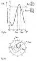
- FIG. 1bshows a schematic plan view of the structural design of the radio station site BS, which comprises three radio coverage areas in the form of three adjoining sectors S1, S2 and S3.
- Each of the sectors S1, S2 or S3is powered by a transmitting antenna formed as a sector antenna 1, 2 and 3, respectively, with an aperture angle of 120 °.
- the mobile communication terminal MSis located directly in the radio coverage area S1 and is in radio communication with the base station (not shown here, see BTS in Fig. 1 a) via the corresponding sector antenna. This means that this sector S1 is the so-called "serving cell” or "active set” corresponds.
- the radio signalsare transmitted from the corresponding transmission antenna (see Fig. 1 in Fig. 1a) in the downlink direction DL to the mobile communication terminal MS. In the reverse direction, ie in the upward direction UL, the mobile communication terminal MS sends its radio signals back to the antenna.
- the radio receiving direction Dis to be determined in the downward direction to be followed by e.g. to enable a position determination of the mobile communication terminal MS.
- Thiscan be done, for example, by determining the radio reception direction D on the one hand and determining the distance between the transmitting antenna and the mobile communication terminal MS, for example, which can be derived from the radio signal transit time TA, which in turn is in the form of a so-called "timimg advance" or "round trip time "is specified.
- the distancecorresponds to a radius around the center of the radio station location BS.
- the radio reception direction Din turn is indicated by an azimuth angle A. On the basis of the radius and the angle then the position of the mobile communication terminal MS can be determined exactly.
- the invention proposed hereis particularly directed to the determination of the radio reception direction.
- the sector-shaped radio coverage areas S1 to S3are aligned such that the radio coverage area S1 points north with its main emission direction, that is to say where the azimuth angle A equals 0 degrees.
- the mobile communication terminal MSis now within the radio field coverage area (radio sector) S1.
- the radio reception direction Dcould now be determined by comparing the reception level measured by the radio communication terminal MS with the antenna diagram of the sector antenna used for the sector S1. This would be but two symmetrical to North direction equally wide open azimuth determined, so that no clear determination of the radio reception direction D could be achieved.
- the radio field attenuationwould have to be known in order to be able to compare the measured reception level with the reference values of the antenna diagram.
- the radio propagation conditions, in particular the radio field attenuationnot stable, but depending on occurring effects, such as radio shading, reflections or fading and weather changes with fluctuating humidity and temperature.
- FIG. 3shows the flowchart for a method 100 according to the invention with the steps 110 to 160, which is embodied here as an iterative method. After the start S of the method, the following iteration parameters are set in a first step 110:
- a first index iwhich is also a loop counter, is set to its initial value equal to 1.
- a maximum value imax corresponding to the number of radio field areas (sectors)is set to 3.
- a second index kis set to i + 1.
- first the reception levels in the different radio field areasare measured.
- a first reception level RLi and a second RLkis determined.
- these measured reception levelsare set in relation to each other, so that a Ratio Rik forms.
- This calculated ratio R12is used later to determine the azimuth angle.
- reference values Tikare retrieved from a look-up table. These reference values represent the characteristic of the reference curve shown in FIG. 4a.
- the transmission-side power level functions TP1 and TP2 for the sectors S1 and S2are set in relation to each other and used as reference values T12.
- the ratio value R12is compared with the reference value T12, and that where equality exists, a corresponding azimuth angle is detected.
- an azimuth angle Ap12which is approximately -20 °
- an azimuth angle Aq12which corresponds to approximately 57 °, are determined (see also FIGS. 4a and 4b). Only one of these two azimuth angles actually points to the desired radio reception direction. The other is not relevant and results from the ambiguous evaluation process.
- a loop with sub-steps 120 to 140is run at least once more.
- step 120the receive values RL2 and RL3 are measured for the corresponding sectors S2 and S3 (step 120), then the ratio value R23 is formed therefrom (step 130), and finally further azimuth angles Ap23 and Aq23 are estimated therefrom (step 140).
- step 160all previously calculated azimuth angles are compared with one another, in order finally to determine the wanted radio reception direction D and then to end the method in step E.
- step 160is also illustrated with reference to FIG. 5, where the estimated azimuth angles are plotted.
- the figureshows that in the range of 50 to 60 ° an accumulation of estimated values is to be noted. By averaging the three estimates available there finally results in a radio reception direction D to 55 °.
- the values R23 and T23relate exclusively to those radio field areas (sectors) which do not directly supply the mobile communication terminal MS. So there are no serving cells or active sets, but so-called “neighbor cells” or “candidate / monitoring sets". These sectors are used for monitoring (monitoring) by the mobile communication terminal MS, which sends there no uplink signals. It is now also possible to use only such monitoring values, ie reception levels measured on the downlink, for determining the azimuth angles and radio reception direction, in particular if there are a plurality of such radio field areas (eg 5 with a sectoring of 60 degrees in each case). This has the advantage that the measured values are not impaired by influences due to a transmission power control to be carried out in the "serving cell" on the local radio channels. For the radio signals to be observed in the "neighbor cells" of the mobile communication device, are radio channels on which is emitted with a constant (maximum) power.
- the method according to the inventioncan already be carried out at a single radio station location, so that it does not require any radio contact with several radio station locations.
- the estimate of the radio reception directionbecomes the more accurate the more iterations can be performed. That in turn depends on the number of available sectors.
- the reception values of different radio sectorsare set in relation to each other, but rather the reception level emanating from an omnidirectional antenna and the reception level emanating from a sector antenna.
- the radio directioncan already be determined within a single radio sector by firstly measuring the reception level on a radio channel emanating from an omnidirectional antenna (for example on the broadcast signaling channel) and on the other hand Receiving level of the corresponding sector antenna (for example, on one of the traffic channels) is measured.
- the presented methodcan be used to determine the position of mobile devices. This is briefly described by way of example with reference to FIG. 6: There, a cellular radio network is assumed, in which each radio station location has a plurality of sector antennas. If the determination of the respective radio reception direction D is now carried out at several radio station locations, but at least at two adjacent ones, a cross bearing is possible with which finally the position of the mobile communication terminal MS is determined. In the example shown in FIG. 6, a reception direction D equal to 55 ° is determined at a radio station location and a reception direction of 290 ° at a second radio station location and a reception direction of 345 ° at a third location.
- a triangleBy overlaying the different directions of reception, a triangle (ideally an intersection) results, which indicates the location area of the mobile communication terminal MS.
- the receive directionis determined only in a single radio cell or radio sector and this is used in connection with a distance determination (signal propagation time measurement) for position calculation.
- the proposed methodcan be combined as desired with other localization and localization methods.
Landscapes
- Engineering & Computer Science (AREA)
- Computer Networks & Wireless Communication (AREA)
- Remote Sensing (AREA)
- Signal Processing (AREA)
- Aviation & Aerospace Engineering (AREA)
- Physics & Mathematics (AREA)
- General Physics & Mathematics (AREA)
- Radar, Positioning & Navigation (AREA)
- Mobile Radio Communication Systems (AREA)
- Radio Relay Systems (AREA)
- Radar Systems Or Details Thereof (AREA)
Abstract
Description
Translated fromGermanDie Erfindung betrifft ein Verfahren zum Bestimmen der Funkempfangsrichtung in Abwärtsrichtung an einem Funkfeststationsstandort in einem Mobilkommunikationsnetz gemäß dem Oberbegriff des Anspruchs 1. Außerdem betrifft die Erfindung ein Mobilkommunikationsnetz mit Vorrichtungen, insbesondere mit einem Rechner, einer Funkfeststation und einem Mobilkommunikationsendgerät, zur Durchführung des Verfahrens entsprechend den Oberbegriffen der nebengeordneten Ansprüche.The invention relates to a method for determining the radio reception direction in the downward direction at a radio station location in a mobile communication network according to the preamble of
In Mobilkommunikationsnetzen, insbesondere in zellularen Mobilkommunikationsnetzen, wie beispielsweise dem GSM (Global System for Mobile Communications) oder dem UMTS (Universal Mobile Telecommunications System), ist es wichtig den momentanen Aufenthaltsort der Mobilfunkteilnehmer zu kennen. Von einem zunehmenden Interesse sind die sogenannten "location based services", das heißt Mobilfunkdienste, die abhängig sind vom momentanen Aufenthaltsort der Mobilfunkteilnehmer. Um diese und ähnliche Dienste durchführen zu können ist es notwendig nicht nur die Funkzelle oder den Funkfeldbereich zu kennen, in dem sich der Funkteilnehmer aufhält, sondern eine genauere Positionsbestimmung bis hin zu wenigen Metern durchzuführen. Verschiedene Verfahren dazu sind bereits bekannt. So etwa ist das sogenannte Triangulations-Verfahren bekannt, bei dem die Abstände des Mobilkommunikationsendgerätes zu benachbarten Funkfeststationen mittels Messung von Funksignallaufzeiten ermittelt werden, wobei an Hand der Kreuzungspunkte von entsprechenden Entfernungsradien der momentane Aufenthaltsort bestimmt wird. Dazu muss aber sowohl der Kontakt zu mindestens zwei entfernten Funkfeststationen bestehen. Außerdem müssen die Funksender der Funkfeststationen aufeinander synchronisiert sein oder es müssen zumindest die Zeitdifferenzen zwischen den Sendesignalen, insbesondere zwischen den Symbolen, bekannt sein.In mobile communication networks, in particular in cellular mobile communication networks, such as the GSM (Global System for Mobile Communications) or the UMTS (Universal Mobile Telecommunications System), it is important to know the current location of the mobile subscriber. Of an increasing interest are the so-called "location based services", ie mobile services that are dependent on the current location of the mobile subscriber. In order to be able to carry out these and similar services, it is necessary not only to know the radio cell or the radio field area in which the radio subscriber is staying, but to carry out a more precise position determination down to a few meters. Various methods are already known. That's about it so-called triangulation method, in which the distances of the mobile communication terminal to neighboring fixed base stations are determined by means of measuring radio signal transit times, the momentary location being determined on the basis of the crossing points of corresponding distance radii. For this, however, both the contact with at least two remote base stations must exist. In addition, the radio transmitters of the base stations must be synchronized with each other, or at least the time differences between the transmission signals, in particular between the symbols, must be known.
Es ist auch bekannt, zunächst die Funkempfangsrichtung mittels der Auswertung von den an Gruppenantennen, sogenannten "smart antennas", vorhandenen Funksignalanteilen zu bestimmen. Dann wird zusätzlich dazu auch die Entfernung zur Funkfeststation (durch Messung der Signallaufzeit) ermittelt, sodass schließlich der Aufenthaltsort genauer bestimmt werden kann. Jedoch sind die bekannten Verfahren mit einem nicht unerheblichen Rechenaufwand verbunden und erfordern bestimmte Voraussetzung, wie etwa den Kontakt zu mehreren Funkfeststationen oder das Vorhandensein von Gruppenantennen.It is also known to first determine the radio reception direction by means of the evaluation of the radio signal components present at group antennas, so-called "smart antennas". Then, in addition to the distance to the base station (by measuring the signal propagation time) is determined, so that finally the whereabouts can be determined more accurately. However, the known methods are associated with a considerable amount of computation and require certain conditions, such as the contact with several base stations or the presence of array antennas.
In der europäischen Patentveröffentlichung EP-A-1094335 wird ein Verfahren zum Bestimmen der Funkempfangsrichtung in Aufwärtsrichtung an einem Funkfeststationsstandort in einem Mobilkommunikationsnetz beschrieben.European Patent Publication EP-A-1094335 describes a method for determining the upstream radio reception direction at a radio station location in a mobile communication network.
In der PCT-Anmeldung WO 99/33302 wird ein Mobilkommunikationsendgerät beschrieben, von dem die Empfangspegel der Funksignale gemessen werden.In PCT application WO 99/33302 a mobile communication terminal is described, from which the reception levels of the radio signals are measured.
Aufgabe der Erfindung ist es ein Verfahren zur Bestimmung der Funkempfangsrichtung vorzustellen, das möglichst einfach realisiert werden kann und dennoch genaue Angaben über die tatsächliche Funkempfangsrichtung liefert. Ebenfalls sollen entsprechende Vorrichtungen dafür vorgestellt werden.The object of the invention is to provide a method for determining the radio reception direction, which can be realized as simply as possible and yet provides accurate information about the actual radio reception direction. Likewise, corresponding devices are to be presented for it.
Gelöst wird die Aufgabe durch ein Verfahren mit den Merkmalen nach Anspruch 1.The object is achieved by a method having the features of
Demnach wird vorgeschlagen, dass von dem jeweiligen Mobilkommunikationsendgerät zumindest die Empfangspegel der Funksignale gemessen werden, die von einer ersten und von einer zweiten des Sendeantennen abgestrahlt werden. Dabei wird aus den beiden gemessenen Empfangspegeln ein Verhältniswert gebildet. Dieser ist weitgehend unabhängig ist von den herrschenden Funkausbreitungsbedingungen, insbesondere von den Pfadverlusten auf den Funkstrecken. Mittels dieses Verhältniswertes wird dann eine Schätzung von Azimutwinkeln für die zu bestimmende Funkempfangsrichtung durchgeführt.Accordingly, it is proposed that at least the reception levels of the radio signals which are emitted by a first and by a second of the transmission antenna be measured by the respective mobile communication terminal. In this case, a ratio value is formed from the two measured reception levels. This is is largely independent of the prevailing radio propagation conditions, in particular of the path losses on the radio links. An estimate of azimuth angles for the radio reception direction to be determined is then carried out by means of this ratio value.
Gleichfalls wird ein zur Durchführung des Verfahrens geeignetes Mobilkommunikationsnetz vorgeschlagen, das einen Rechner enthält, der mit dem Funkfeststationsstandort verbunden ist und der aus den beiden gemessenen Empfangspegeln den Verhältniswert bildet und damit wiederum die Azimutwinkel schätzt.Likewise proposed is a mobile communication network suitable for carrying out the method, which contains a computer which is connected to the radio station location and which forms the ratio value from the two measured reception levels and in turn estimates the azimuth angles.
Die Erfindung lässt sich also an jedem einzelnen Funkfeststationsstandort bereits vollständig durchführen. Es ist kein Kontakt zu mehreren Funkfeststationen notwendig. Außerdem werden Messwerte verwertet, nämlich die Empfangspegel der Funksignale, die in vielen Fallen schon für andere Zwecke, wie beispielsweise für Handover-Messungen ermittelt werden müssen und somit bereits im Mobilkommunikationsnetz vorliegen. Diese Messwerte werden z.B. im Rahmen eines sogenannten Measurement-Reports von den Mobilkommunikationsendgeräten zu dem Funkfeststandort übertragen. Durch das erfindungsgemäße Berechnen eines Verhältniswertes wird erreicht, dass die die Empfangspegelwerte beeinträchtigenden Größen eliminiert werden, insbesondere die für die Funkausbreitungsbedingungen charakteristischen Größen, wie etwa Funkfelddampfung oder Pfadverlust. Diese Größen sind stark abhängig von der gegebenen Situation, wie etwa Sichtfunkverbindung, Funkabschattung, Fading, Reflexionen oder Waveguide-Effekte. Die Erfindung geht von der Erkenntnis aus, dass beide miteinander ins Verhältnis gesetzte Empfangspegel gleichermaßen beeinträchtigt werden, sofern sich die beiden Sendeantennen am selben Ort, vorzugsweise am selben Antennenmast, montiert sind. In diesem Fall wird durch die Bildung des Verhältniswertes (Quotientenbildung) ein Relativwert gewonnen, der weitestgehend unabhängig ist von den Funkausbreitungsbedingungen und der somit eine verlässliche Schätzung der Azimutwinkel und Bestimmung der Funkempfangsrichtung ermöglicht. Zudem ist die Quotientenbildung einfach und schnell auszuführen. Insgesamt wird also ein sehr einfach zu realisierendes aber doch sehr zuverlässiges Verfahren vorgeschlagen.The invention can thus be carried out completely at each individual radio station location. There is no need to contact several base stations. In addition, measured values are utilized, namely the reception levels of the radio signals, which in many cases already have to be determined for other purposes, such as, for example, for handover measurements and are thus already present in the mobile communications network. These measured values are transmitted, for example as part of a so-called measurement report from the mobile communication terminals to the radio-controlled site. By calculating a ratio value according to the invention, it is achieved that the magnitudes affecting the received level values are eliminated, in particular the variables characteristic for the radio propagation conditions, such as radio field vaporization or path loss. These quantities are highly dependent on the given situation, such as visual radio connection, radio shading, fading, reflections or waveguide effects. The invention is based on the recognition that both reception levels set in relation to one another are equally impaired if the two transmission antennas are mounted at the same location, preferably on the same antenna mast. In this case, the formation of the ratio value (quotient formation) yields a relative value which is largely independent of the radio propagation conditions and thus makes possible a reliable estimation of the azimuth angles and determination of the radio reception direction. In addition, the quotient is easy and fast to execute. Overall, therefore, a very easy to implement but very reliable method is proposed.
Besonders vorteilhafte Ausgestaltungen der Erfindung ergeben sich aus den Unteransprüchen:Particularly advantageous embodiments of the invention will become apparent from the subclaims:
Demnach ist es von besonderem Vorteil, wenn die Azimutwinkel dadurch geschätzt werden, dass der gebildete Verhältniswert mit vorgegebenen Referenzwerten verglichen wird, die für verschiedene Azimutswinkel den zu erwartenden Verhältniswert angeben. Die Referenzwerte sind Sendeleistungswerte, die in Hauptstrahlrichtung dem EIRP-Wert (EIRP: effective isotopic radiated power - effektive isotopische Strahlungsleistung) entsprechen und die in den anderen Richtungen den aufgrund des Antennendiagramms gedämpften Sendeleistungswerten entsprechen. Auch die Referenzwerte werden, die also die winkelabhängige Verteilung der Strahlungsleistung an den Sendeantennen angeben, werden ebenfalls ins Verhältnis zueinander gesetzt und werden vorzugsweise in Nachschlagtabellen abgelegt. Somit ist es möglich, ein schnelles und effektives look-up-table-Verfahren durchzuführen, das den Rechenaufwand noch weiter reduziert. Durch den Vergleich von Verhältniswerten auf der Empfangsseite (Messwerte) mit Verhältniswerten auf der Sendeseite (Referenzwerte) ist es möglich, dass die Azimutwinkel ohne Kenntnis der Funkfelddämpfung geschätzt werden können.Accordingly, it is of particular advantage if the azimuth angles are estimated by comparing the formed ratio value with predetermined reference values which indicate the expected ratio value for different azimuth angles. The reference values are transmission power values that correspond in the main beam direction to the EIRP value (effective isotopic radiated power) and which in the other directions correspond to the transmission power values damped due to the antenna pattern. The reference values, which also indicate the angle-dependent distribution of the radiation power at the transmitting antennas, are likewise set in relation to one another and are preferably stored in look-up tables. Thus, it is possible to perform a fast and effective look-up table method that further reduces the computational burden. By comparing ratio values on the receiving side (measured values) with ratio values on the transmitting side (reference values), it is possible that the azimuth angles can be estimated without knowledge of the radio field attenuation.
Auch ist es von besonderem Vorteil, wenn die Sendeantennen Sektorantennen oder Gruppenantennen sind und wenn die Funkversorgungsbereiche Funksektoren sind, welche jeweils von einer der Sektorantennen beziehungsweise Gruppenantennen versorgt werden. In diesem Zusammenhang ist es sehr vorteilhaft , wenn die beiden Sendeantennen, von deren Funksignalen die Empfangspegel gemessen werden, zwei zueinander benachbarte Funkversorgungsbereiche versorgen, und wenn das Mobilkommunikationsendgerät sich zumindest in einem dieser beiden Funkversorgungsbereiche aufhält. Dadurch werden die am stärksten vorherrschenden Empfangspegel miteinander ins Verhältnis gesetzt, was die Zuverlässigkeit der Berechnungsmethode weiterhin verbessert.It is also of particular advantage if the transmitting antennas are sector antennas or group antennas and if the radio coverage areas are radio sectors, which are each supplied by one of the sector antennas or group antennas. In this context, it is very advantageous if the two transmit antennas, from whose radio signals the receive levels are measured, supply two mutually adjacent radio coverage areas, and if the mobile communication terminal is located at least in one of these two radio coverage areas. As a result, the most prevalent reception levels become intertwined Ratio, which further improves the reliability of the calculation method.
Unabhängig davon oder auch im Zusammenhang damit ergibt sich ein weiterer besonderer Vorteil, wenn von dem Mobilkommunikationsendgerät auch diejenigen Empfangspegel der Funksignale gemessen werden, die von den übrigen Sendeantennen abgestrahlt werden, wobei aus jeweils zwei gemessenen Empfangspegeln ein Verhältniswert gebildet wird. Dann wird mittels dieser weiteren Verhältniswerten die Schätzung von weiteren Azimutwinkeln durchgeführt und schließlich mittels aller geschätzten Azimutwinkeln wird die Funkempfangsrichtung genauer bestimmt. Es wird also ein iteratives Verfahren vorgeschlagen, bei dem paarweise die Empfangspegel ins Verhältnis zu einander gesetzt werden, wobei die vielen sich ergebenden Verhältniswerte eine noch genauere Schätzung der Azimutwinkel und damit auch eine noch zuverlässigere Bestimmung der Funkempfangsrichtung ermöglichen.Regardless of or in connection therewith, a further particular advantage results if the mobile communication terminal also measures those reception levels of the radio signals which are emitted by the other transmission antennas, with a ratio value being formed from two measured reception levels each. Then, by means of these further ratio values, the estimation of further azimuth angles is carried out, and finally by means of all estimated azimuth angles, the radio reception direction is determined more accurately. Thus, an iterative method is proposed in which the reception levels are set in pairs in relation to each other, the many resulting ratio values allowing an even more accurate estimation of the azimuth angles and thus also an even more reliable determination of the radio reception direction.
Es ist außerdem von besonderem Vorteil, wenn eine der Sendeantennen eine Rundstrahlantenne ist, von der der gesamte Bereich des Funkfeststationsstandortes versorgt wird, und wenn die anderen Sendeantennen Sektor- oder Gruppenantennen sind, von denen sektorförmige Funkversorgungsbereiche versorgt werden. Dabei werden von dem Mobilkommunikationsendgerät die Empfangspegel gemessen, die sowohl von Funksignalen der Rundstrahlantennen als auch von Funksignalen der Sektor- beziehungsweise Gruppenantenne herstammen. In diesem Fall kann also auch eine Bestimmung der Funkempfangsrichtung erfolgen innerhalb des jeweiligen Funkversorgungsbereichs, von dem das Mobilkommunikationsendgerät direkt versorgt wird, wobei zum einen auf den Empfangspegel bezüglich der Rundstrahlantenne (z.B. Empfangspegel auf dem Rundspruchsignalisierungskanal) und zum anderen auf den Empfangspegel des Versorgungsbereiches (z.B. Empfangspegel auf dem Nachrichtenkanal innerhalb des Sektors) zurückgegriffen wird.It is also particularly advantageous if one of the transmit antennas is an omnidirectional antenna that powers the entire area of the base station site and if the other transmit antennas are sector or array antennas that provide sector-shaped coverage areas. In this case, the reception levels are measured by the mobile communication terminal, which originate both from radio signals of the omnidirectional antennas and of radio signals of the sector or group antenna. In this case, therefore, a determination of the radio reception direction can also take place within the respective radio coverage area from which the mobile communication terminal is directly supplied, on the one hand to the reception level with respect to the omnidirectional antenna (eg reception level on the Rundspruchignalisierungskanal) and on the other hand to the reception level of the coverage area (eg Reception level on the message channel within the sector).
Die Erfindung selbst sowie die sich daraus ergebenden Vorteile werden nun an Hand eines Ausführungsbeispieles beschrieben, wobei auf die folgenden Figuren bezug genommen wird:
- Figur 1a,
- die den Aufbau eines erfindungsgemäßen Mobilkommunikationsnetzes zeigt;
- Figur 1b,
- die die Struktur eines Funkfeststationsstandortes zeigt;
- Figur 2a und 2b,
- die den Sendeleistungspegelverlauf (Antennendiagramme oder Funktionen) der Funkversorgungsbereiche am Funkfeststationsstandort zeigen;
Figur 3,- die das Ablaufdiagramm eines erfindungsgemäßen Verfahrens zeigt;
- Figur 4a und 4b,
- die die zu erwartenden Verhältniswerte für verschiedene Azimutwinkel zeigen;
- Figur 5,
- die die Verteilung mehrerer Azimutwinkel und die daraus resultierende Funkempfangsrichtung zeigt; und
- Figur 6,
- die ein Prinzip zur genauen Positionsbestimmung einem zellularen Funknetz unter Zuhilfenahme des erfindungsgemäßen Verfahrens verdeutlicht.
- FIG. 1a,
- showing the construction of a mobile communication network according to the invention;
- FIG. 1b,
- showing the structure of a radio station site;
- FIGS. 2a and 2b,
- showing the transmission power level profile (antenna diagrams or functions) of the radio coverage areas at the radio station location;
- FIG. 3,
- showing the flow diagram of a method according to the invention;
- FIGS. 4a and 4b
- showing the expected ratio values for different azimuth angles;
- FIG. 5,
- showing the distribution of multiple azimuth angles and the resulting radio reception direction; and
- FIG. 6,
- which illustrates a principle for precise position determination of a cellular radio network with the aid of the method according to the invention.
Die Figur 1a zeigt den schematischen Aufbau eines erfindungsgemäßen Mobilkommunikationsnetzes mit mindestens einem Funkfeststationsstandort BS, der an das Kernnetzwerk CN des Mobilkommunikationsnetzes angeschlossen ist. An dem Funkfeststationsstandort BS befindet sich eine Funkfeststation BTS mit drei Funksendern T1, T2 und T3, die verschiedene Funkversorgungsbereiche (siehe S1 bis S3 in der Fig. 1b) des Funkfeststationsstandortes BS versorgen. Die Funksender müssen sich nicht in einer einzigen Funkfeststation befinden, sondern können auch jeweils in einer anderen Funkfeststation integriert sein. Dies kann etwa dann der Fall sein, wenn verschiedene Funkübertragungsverfahren in den Funkversorgungsbereichen zum Einsatz kommen.1a shows the schematic structure of a mobile communication network according to the invention with at least one radio station location BS, which is connected to the core network CN of the mobile communication network. At the radio station site BS there is a base station BTS with three radio transmitters T1, T2 and T3, which supply different radio coverage areas (see S1 to S3 in Figure 1b) of the radio station site BS. The radio transmitters do not have to be in a single base station, but can each be in a different base station Base station be integrated. This may be the case, for example, when various radio transmission methods are used in the radio coverage areas.
Jeder der Funksender T1, T2 oder T3 sendet über eine Sendeantenne, die hier eine Sektorantenne 1, 2 bzw. 3 ist, in seinem Funkversorgungsbereich Funksignale an Mobilkommunikationsendgeräte, von denen beispielhaft eines MS in der Fig. 1a eingezeichnet ist. Es ist für die Rechengenauigkeit des Verfahrens aber vorteilhaft, wenn die Sendeantennen 1, 2 und 3 möglichst an demselben Ort, z.B. auf einem Antennenmast, montiert sind. Das hier dargestellte Mobilkommunikationsendgerät MS befindet sich in direkter Funkverbindung mit dem Sender T1 der Funkfeststation BTS. Die Funkfeststation ist unter anderem mit einem Rechner C, der sich im Kernnetzwerk CN befindet, verbunden. In diesem Beispiel ist der Rechner C in der in der Funkvermittlungsstelle (Mobile Switching Center) integriert und ermittelt nun nach dem noch später genau beschriebenen Verfahren die Funkempfangsrichtung, mittels der z.B. die genaue Position des Mobilkommunikationsendgerätes MS schließlich bestimmt werden kann. Der Rechner kann auch an anderen Stellen installiert werden, so etwa im Funkzugangsnetzwerk, insbesondere in der Funkfeststationssteuerung (base station controller) oder in der Funknetzsteuerung (Radio Network Controller), ebenfalls auch in Datenknotenpunkten, wie etwa dem sogenannten Gateway GPRS Support Node (GPRS: General Packet Radio Service) oder dem Serving GPRS Support Node für das UMTS.Each of the radio transmitters T1, T2 or T3 transmits, via a transmitting antenna, which here is a
Die Figur 1b zeigt schematischen in der Draufsicht den strukturellen Aufbau des Funkfeststationsstandortes BS, der drei Funkversorgungsbereiche in Form von drei aneinander grenzenden Sektoren S1, S2 und S3, umfasst. Jeder der Sektoren S1, S2 oder S3 wird von einer Sendeantenne versorgt, die als Sektorantenne 1, 2 bzw. 3 mit einem Öffnungswinkel von 120° ausgebildet ist. Das Mobilkommunikationsendgerät MS befindet sich direkt im Funkversorgungsbereich S1 und steht in Funkverbindung mit der Funkfeststation (hier nicht dargestellt; siehe BTS in der Fig. 1 a) über die entsprechende Sektorantenne. Das bedeutet, dass dieser Sektor S1 der sogenannten "serving cell" oder auch "active set" entspricht. Die Funksignale werden von der entsprechenden Sendeantenne (siehe 1 in Fig. 1a) in Abwärtsrichtung DL zu dem Mobilkommunikationsendgerät MS übertragen. In umgekehrter Richtung, d.h. in Aufwärtsrichtung UL, sendet das Mobilkommunikationsendgerät MS seine Funksignale zurück an die Antenne.FIG. 1b shows a schematic plan view of the structural design of the radio station site BS, which comprises three radio coverage areas in the form of three adjoining sectors S1, S2 and S3. Each of the sectors S1, S2 or S3 is powered by a transmitting antenna formed as a
Es soll nun die Funkempfangsrichtung D in Abwärtsrichtung bestimmt werden, um danach z.B. eine Positionsbestimmung des Mobilkommunikationsendgerätes MS zu ermöglichen. Dies kann beispielsweise dadurch erfolgen, dass zum einen die Funkempfangsrichtung D ermittelt wird und zum anderen der Abstand zwischen Sendeantenne und Mobilkommunikationsendgerät MS ermittelt wird, der sich aus der Funksignallaufzeit TA ableiten lässt, die wiederum in Form eines sogenannten "timimg advance" oder auch "round trip time" angegeben ist. Der Abstand entspricht einem Radius um den Mittelpunkt des Funkfeststationsstandortes BS. Die Funkempfangsrichtung D wiederum wird durch einen Azimutwinkel A angegeben. An Hand von dem Radius und dem Winkel lässt sich dann die Position des Mobilkommunikationsendgerätes MS genau bestimmen. Die hier vorgeschlagene Erfindung ist jedoch besonders auf die Bestimmung der Funkempfangsrichtung gerichtet.Now, the radio receiving direction D is to be determined in the downward direction to be followed by e.g. to enable a position determination of the mobile communication terminal MS. This can be done, for example, by determining the radio reception direction D on the one hand and determining the distance between the transmitting antenna and the mobile communication terminal MS, for example, which can be derived from the radio signal transit time TA, which in turn is in the form of a so-called "timimg advance" or "round trip time "is specified. The distance corresponds to a radius around the center of the radio station location BS. The radio reception direction D in turn is indicated by an azimuth angle A. On the basis of the radius and the angle then the position of the mobile communication terminal MS can be determined exactly. However, the invention proposed here is particularly directed to the determination of the radio reception direction.
Wie an Hand der Figur 1b dargestellt sind die sektorförmigen Funkversorgungsbereiche S1 bis S3 derart ausgerichtet, dass der Funkversorgungsbereich S1 mit seiner Hauptabstrahlrichtung in Richtung Norden zeigt, das heißt dahin zeigt, wo der Azimutwinkel A gleich 0 Grad beträgt. Die anderen um jeweils 120 Grad versetzten Sektoren S2 und S3 zeigen demnach in ihre Hauptrichtungen 120 Grad beziehungsweise 240 Grad. Das Mobilkommunikationsendgerät MS befindet sich nun innerhalb des Funkfeldversorgungsbereichs (Funksektors) S1. Man könnte nun die Funkempfangsrichtung D dadurch bestimmen, dass der von dem Funkkommunikationsendgerät MS gemessene Empfangspegel verglichen wird mit dem Antennendiagramm der für den Sektor S1 verwendeten Sektorantenne. Dadurch würden aber zunächst zwei symmetrisch zur Nordrichtung gleichermaßen weit geöffnete Azimutwinkel ermittelt, so dass keine eindeutige Bestimmung der Funkempfangsrichtung D erzielt werden könnte. Außerdem müsste die Funkfelddämpfung bekannt sein, um den gemessenen Empfangspegel mit den Referenzwerten des Antennendiagramms, vergleichen zu können. Zudem sind die Funkausbreitungsbedingungen, insbesondere die Funkfelddämpfung, nicht stabil, sondern abhängig von auftretenden Effekten, wie etwa Funkabschattung, Reflexionen oder Fading und Wetteränderungen mit schwankender Luftfeuchtigkeit und Temperatur. Schon allein die Probleme mit Funkabschattung und Relexionen, wie sie besonders häufig in dichtbesiedelten und städtischen Gebieten auftreten, erschweren eine zuverlässige Bestimmung der Funkempfangsrichtung nach den herkömmlichen Methoden oder machen sie gar unmöglich.As illustrated with reference to FIG. 1b, the sector-shaped radio coverage areas S1 to S3 are aligned such that the radio coverage area S1 points north with its main emission direction, that is to say where the azimuth angle A equals 0 degrees. The other sectors S2 and S3, offset by 120 degrees, thus show 120 degrees and 240 degrees respectively in their main directions. The mobile communication terminal MS is now within the radio field coverage area (radio sector) S1. The radio reception direction D could now be determined by comparing the reception level measured by the radio communication terminal MS with the antenna diagram of the sector antenna used for the sector S1. This would be but two symmetrical to North direction equally wide open azimuth determined, so that no clear determination of the radio reception direction D could be achieved. In addition, the radio field attenuation would have to be known in order to be able to compare the measured reception level with the reference values of the antenna diagram. In addition, the radio propagation conditions, in particular the radio field attenuation, not stable, but depending on occurring effects, such as radio shading, reflections or fading and weather changes with fluctuating humidity and temperature. Already the problems with Funkabschattung and Relexionen, as they occur particularly often in densely populated and urban areas, make it difficult to reliably determine the radio reception direction by conventional methods or even impossible.
Deshalb wird hier ein neues Verfahren vorgeschlagen, dass unter anderem auch an Hand der Figur 2 im weiteren näher beschrieben wird:Therefore, a new method is proposed here, which is described in more detail below, inter alia, with reference to FIG. 2:
Die Figur 3 zeigt das Ablaufdiagramm für ein erfindungsgemäßes Verfahren 100 mit den Schritten 110 bis 160, das hier als iteratives Verfahren ausgebildet ist. Nach dem Start S des Verfahrens werden in einem ersten Schritt 110 folgende Iterations-Parameter gesetzt:FIG. 3 shows the flowchart for a
Ein erster Index i, der auch Schleifenzähler ist, wird auf seinen Anfangswert gleich 1 gesetzt. Ein Maximalwert imax, der der Anzahl der Funkfeldbereiche (Sektoren) entspricht, wird zu 3 gesetzt. Und ein zweiter Index k wird zu i+ 1 gesetzt.A first index i, which is also a loop counter, is set to its initial value equal to 1. A maximum value imax corresponding to the number of radio field areas (sectors) is set to 3. And a second index k is set to i + 1.
In dem nachfolgenden Schritt 120 werden zunächst die Empfangspegel in den verschiedenen Funkfeldbereichen gemessen. Dabei wird ein erster Empfangspegel RLi und ein zweiter RLk ermittelt. Für den ersten Durchlauf bedeutet dies, dass der Empfangswert RL1 für den ersten Sektor und der Empfangswert RL2 für den zweiten Sektor (siehe S1 und S2 in der Figur 1 b) gemessen werden.In the
Dann werden in einem nächsten Schritt 130 diese gemessenen Empfangspegel zueinander in das Verhältnis gesetzt, so dass sich ein Verhältniswert Rik bildet. In diesem Fall bedeutet dies, dass der Verhältniswert R12 aus dem Verhältnis von RL1 zu RL2 gebildet wird. Dieser berechnete Verhältniswert R12 wird später zur Bestimmung der Azimutwinkel herangezogen. In einem Zwischenschritt 135 werden Referenzwerte Tik aus einer Nachschlagetabelle (look-up-table) abgerufen. Diese Referenzwerte geben die Charakteristik der in der Figur 4a dargestellten Referenzkurve wieder. In diesem ersten Fall handelt es sich also um die Referenzwerte T12, die einer Kurve entsprechen, die dem Verhältnis des Sendeleistungspegel TP1 zu dem Sendeleistungspegel TP2 entspricht. Es werden also die sendeseitigen Leistungspegelfunktionen TP1 und TP2 für die Sektoren S1 und S2 (siehe Fig. 1b sowie 2b und 2b) zueinander ins Verhältnis gesetzt und als Referenzwerte T12 herangezogen.Then, in a
In einem nun folgenden Schritt 140 werden sowohl die Referenzwerte Tik=T12 als auch die ermittelten Verhältniswerte Rik=R12 miteinander verglichen, um daraus die gesuchten Azimutwinkel Apik=Ap12 und Aqik=Aq12 zu ermitteln (siehe dazu auch Figur 4a). Für diesen Fall bedeutet es, dass der Verhältniswert R12 mit dem Referenzwert T12 verglichen wird und dass dort wo Gleichheit herrscht, ein entsprechender Azimutwinkel festgestellt wird. In diesem Fall werden also ein Azimutwinkel Ap12, der etwa -20° und ein Azimutwinkel Aq12, der etwa 57° entspricht ermittelt (siehe auch Figuren 4a und 4b). Nur einer dieser beiden Azimutwinkel zeigt tatsächlich in die gesuchte Funkempfangsrichtung. Der andere ist nicht relevant und ergibt sich aufgrund der zweideutigen Auswertungsverfahrens.In a following
Um nun herauszufinden, welcher Azimutwert der richtige ist, wird eine Schleife mit den Teilschritten 120 bis 140 zumindest noch einmal durchlaufen.In order to find out which azimuth value is the right one, a loop with
Dazu wird zunächst festgestellt ob der Zähler i bereits den Maximalwert imax erreicht hat (Schritt 150). In diesem Beispiel also wird geprüft, ob i = imax = 3 ist. der Ist dies nicht der Fall so wird in einem Schritt 151 der Zähler i um 1 erhöht und anschließend in einem Schritt 152 geprüft, ob jetzt der Zähler seinen Maximalwert imax erreicht hat. Ist dies nicht der Fall so folgt direkt der Schritt 120 und nachfolgende Schritte 130, 135, 140 usw.. Das bedeutet, dass im zweiten Durchlauf (i=2) die Empfangswerte RL2 und RL3 für die entsprechenden Sektoren S2 und S3 gemessen werden (Schritt 120), dass dann daraus der Verhältniswert R23 gebildet wird (Schritt 130), und dass schließlich daraus weitere Azimutwinkel Ap23 und Aq23 geschätzt werden (Schritt 140).For this purpose, it is first determined whether the counter i has already reached the maximum value imax (step 150). In this example, it is checked whether i = imax = 3. If this is not the case, then in a
Wird jedoch im Schritt 152 festgestellt, dass der Zähler bereits seinen Maximalwert erreicht hat (i = 3), d.h. hier dass die Schleife bereits zweimal durchlaufen wurde, so wird in einem Schritt 153 der zweite Index zu k=1 gesetzt. Das bedeutet in diesem Fall, dass nun im Schritt 120 die Empfangspegelwerte RL3 und RL1 gemessen werden. Damit wird also auch das letztmögliche Pärchen bezüglich der Sektoren S3 und S1 gebildet und der entsprechende Verhältniswert R31 bestimmt. Schließlich folgt auch hierzu die Schätzung der Azimutwinkel Ap31 und Aq31. Nach dem dritten Durchlauf der Schleife wird dann an Hand der Entscheidungsstufe 150 festgestellt, dass der Zähler seinen Maximalwert erreicht hat (i = imax = 3) erreicht hat und es folgt der Schritt 160.However, if it is determined in
In diesem Schritt 160 werden nun alle zuvor errechneten Azimutwinkel miteinander verglichen, um dann abschließend die gesuchte Funkempfangsrichtung D zu bestimmen und danach das Verfahren im Schritt E zu beenden.In this
Die Vorgehensweise im Schritt 160 wird auch an Hand der Figur 5 verdeutlicht, wo die geschätzten Azimutwinkel aufgetragen sind. An der Figur zeigt sich, dass im Bereich von 50 bis 60 ° eine Anhäufung der Schätzwerte zu bemerken ist. Durch eine Mittelwertbildung der dort vorliegenden drei Schätzwerte ergibt sich schließlich eine Funkempfangsrichtung D zu 55°.The procedure in
Die Werte R23 und T23 beziehen sich ausschließlich auf solche Funkfeldbereiche (Sektoren), die das Mobilkommunikationsendgerät MS nicht direkt versorgen. Es sind also keine "serving cells" oder "active sets", sondern sogenannte "neighbor cells" oder "candidate/monitoring sets". Diese Sektoren dienen der Beobachtung (Monitoring) durch das Mobilkommunikationsendgerätes MS, welches dort keine Uplink-Signale sendet. Man kann nun auch lediglich solche Monitoringwerte, d.h. auf dem Downlink gemessene Empfangspegel, zur Bestimmung der Azimutwinkel und Funkempfangsrichtung heranziehen, insbesondere dann, wenn es mehrere solcher Funkfeldbereiche gibt (z.B. 5 bei einer Sektorisierung von jeweils 60 Grad). Das hat den Vorteil, dass die Messwerte nicht von Einflüssen aufgrund von einer in der "serving cell" durchzuführenden Sendeleistungssteuerung auf den dortigen Funkkanälen beeinträchtigt werden. Denn die Funksignale, die in den "neighbor cells" von dem Mobilkommunikationsgerät zu beachten sind, sind Funkkanäle, auf denen mit einer konstanten (Maximal-) Leistung abgestrahlt wird.The values R23 and T23 relate exclusively to those radio field areas (sectors) which do not directly supply the mobile communication terminal MS. So there are no serving cells or active sets, but so-called "neighbor cells" or "candidate / monitoring sets". These sectors are used for monitoring (monitoring) by the mobile communication terminal MS, which sends there no uplink signals. It is now also possible to use only such monitoring values, ie reception levels measured on the downlink, for determining the azimuth angles and radio reception direction, in particular if there are a plurality of such radio field areas (eg 5 with a sectoring of 60 degrees in each case). This has the advantage that the measured values are not impaired by influences due to a transmission power control to be carried out in the "serving cell" on the local radio channels. For the radio signals to be observed in the "neighbor cells" of the mobile communication device, are radio channels on which is emitted with a constant (maximum) power.
Das erfindungsgemäße Verfahren kann bereits an einem einzigen Funkfeststationsstandort durchgeführt werden, so dass es keines Funkkontaktes mit mehreren Funkfeststationsstandorten bedarf. Die Schätzung der Funkempfangsrichtung wird um so genauer, je mehr Iterationen durchgeführt werden können. Das wiederum hängt auch von der Anzahl der vorhandenen Sektoren ab. Es ist jedoch auch denkbar, dass nicht die Empfangswerte von verschiedenen Funksektoren miteinander ins Verhältnis gesetzt werden, sondern etwa der Empfangspegel der von einer Rundstrahlantenne ausgeht und der Empfangspegel der von einer Sektorantenne ausgeht. Das heißt, dass bereits innerhalb eines einzelnen Funksektors die Funkrichtung bestimmt werden kann, indem zum einen der Empfangspegel auf einem Funkkanal gemessen wird, der von einer Rundstrahlantenne ausgeht (zum Beispiel auf dem Rundspruchsignalisierungskanal, dem sogenannten "broadcast control channel") und zum anderen der Empfangspegel der entsprechenden Sektorantenne (zum Beispiel auf einem der Verkehrskanäle) gemessen wird. An Stelle von Sektorantennen ist es natürlich auch denkbar, dass Gruppenantennen zum Einsatz kommen. Unabhängig von der Art der eingesetzten Antennen ergibt sich der Vorteil der Erfindung bereits dadurch, dass nicht absolute Empfangspegel sondern Verhältniswerte (also relative Empfangspegel) berechnet werden und mit entsprechenden Referenzwerten verglichen werden. Das hat unter anderem den Vorteil, dass die vorgestellte Berechnungsmethode unabhängig ist von Funkausbreitungsbedingungen.The method according to the invention can already be carried out at a single radio station location, so that it does not require any radio contact with several radio station locations. The estimate of the radio reception direction becomes the more accurate the more iterations can be performed. That in turn depends on the number of available sectors. However, it is also conceivable that not the reception values of different radio sectors are set in relation to each other, but rather the reception level emanating from an omnidirectional antenna and the reception level emanating from a sector antenna. This means that the radio direction can already be determined within a single radio sector by firstly measuring the reception level on a radio channel emanating from an omnidirectional antenna (for example on the broadcast signaling channel) and on the other hand Receiving level of the corresponding sector antenna (for example, on one of the traffic channels) is measured. Of course, instead of sector antennas, it is also conceivable that group antennas are used. Regardless of the type of antennas used, the advantage of the invention already results from the fact that not absolute reception levels but ratio values (ie relative reception levels) are calculated and with corresponding reference values. This has the advantage that the presented calculation method is independent of radio propagation conditions.
Das vorgestellte Verfahren kann zu einer Positionsbestimmung von Mobilfunkgeräten verwendet werden. Dies wird beispielhaft an Hand der Figur 6 kurz beschrieben: Dort wird von einem zellularen Funknetz ausgegangen, bei dem jeder Funkfeststationsstandort über mehrere Sektorantennen verfügt. Wird nun an mehreren Funkfeststationsstandort, zumindest aber an zwei benachbarten, die Bestimmung der jeweiligen Funkempfangsrichtung D durchgeführt, so ist eine Kreuzpeilung möglich, mit der schließlich die Position des Mobilkommunikationsendgerätes MS bestimmt werden. In dem in Figur 6 dargestellten Beispiel wird an einem Funkfeststationsstandort eine Empfangsrichtung D gleich 55° ermittelt und an einem zweiten Funkfeststationsstandort eine Empfangsrichtung von 290° sowie an einem dritten Standort eine Empfangsrichtung von 345°. Durch eine Überlagerung der verschiedenen Empfangsrichtungen ergibt sich ein Dreieck (im Idealfall ein Schnittpunkt), das den Aufenthaltsbereich des Mobilkommunikationsendgerätes MS angibt. Es sind natürlich auch Verfahren denkbar, bei dem nur in einer einzigen Funkzelle oder Funksektor die Empfangsrichtung bestimmt wird und diese im Zusammenhang mit einer Entfernungsbestimmung (Signallaufzeitmessung) zur Positionsberechnung herangezogen wird. Das vorgestellte Verfahren ist beliebig kombinierbar mit anderen Ortungs- und Lokalisierungsverfahren.The presented method can be used to determine the position of mobile devices. This is briefly described by way of example with reference to FIG. 6: There, a cellular radio network is assumed, in which each radio station location has a plurality of sector antennas. If the determination of the respective radio reception direction D is now carried out at several radio station locations, but at least at two adjacent ones, a cross bearing is possible with which finally the position of the mobile communication terminal MS is determined. In the example shown in FIG. 6, a reception direction D equal to 55 ° is determined at a radio station location and a reception direction of 290 ° at a second radio station location and a reception direction of 345 ° at a third location. By overlaying the different directions of reception, a triangle (ideally an intersection) results, which indicates the location area of the mobile communication terminal MS. Of course, methods are also conceivable in which the receive direction is determined only in a single radio cell or radio sector and this is used in connection with a distance determination (signal propagation time measurement) for position calculation. The proposed method can be combined as desired with other localization and localization methods.
Claims (6)
- A process (100) for determining the radio reception direction (D) on the downlink (DL) at a radio base station location (BS) in a mobile communications network, wherein at least two spatial radio coverage areas (S1, S2, S3) are covered by the radio base station location (BS), wherein in each radio coverage area (S1) on the downlink (DL) radio signals are radiated by means of a transmitting antenna (1) for reception by at least one mobile communications terminal (MS),characterised in that at least the reception levels (RL1, RL2) of the radio signals radiated by a first (1) and a second (2) of the transmitting antennae are measured by the relevant mobile communications terminal (MS) (120), that a ratio value (R12) is formed from the two measured reception levels (RL1, RL2) (130), and that by means of this ratio value (R12) an estimation is effected of azimuthal angles (Ap12, Aq12) for the radio reception direction (D) to be determined (160).
- A process (100) according to Claim 1,characterised in that the azimuthal angles (Ap12 , Aq12) are estimated by comparing the formed ratio value (R12) with predetermined reference values (T12) indicating the expected ratio value for different azimuthal angles (A) (260).
- A process (100) according to Claim 1,characterised in that the transmitting antennae are sector antennae (1, 2, 3) or group antennae, and that the radio coverage areas are radio sectors (S1, S2, S3) which are each supplied by one of the sector antennae (1, 2, 3) or group antennae.
- A process (100) according to Claim 2,characterised in that the two transmitting antennae (1, 2), whose radio signals are measured in respect of the reception levels (RL1, RL2) (120), supply two mutually adjacent radio coverage areas (S1, S2) and that the mobile communications terminal (MS) is situated at least in one (S1) of these two radio coverage areas.
- A process according to Claim 1,characterised in that one of the transmitting antennae is an omnidirectional antenna by which the whole area of the radio base station location and therefore at least two spatial radio coverage areas are supplied, that the other transmitting antennae are sector antennae or group antennae by which sector-shaped radio coverage areas are supplied, and that the mobile communications terminal measures the reception levels which emanate from radio signals radiated by the omnidirectional antenna and which emanate from radio signals radiated at least by that sector- or group antenna which supplies the radio coverage area in which the mobile communications terminal is located.
- A process (100) according to Claim 1,characterised in that the reception levels (RL3) of the radio signals radiated by the other transmitting antennae (3) are also measured by the mobile communications terminal (MS) (120), that a ratio value (R31) which is independent of the prevailing radio propagation conditions is in each case formed from two measured reception levels (RL3, RL1) (130), that these further ratio values (R31) are used to effect the estimation of further azimuthal angles (Ap31, Aq31) for the radio reception direction (D) to be determined, and that the radio reception direction (D) is determined by means of all the estimated azimuthal angles (160).
Priority Applications (5)
| Application Number | Priority Date | Filing Date | Title |
|---|---|---|---|
| AT02360074TATE325351T1 (en) | 2002-02-28 | 2002-02-28 | METHOD AND DEVICE FOR DETERMINING THE RADIO RECEPTION DIRECTION IN A MOBILE COMMUNICATIONS NETWORK |
| DE50206652TDE50206652D1 (en) | 2002-02-28 | 2002-02-28 | Method and apparatus for determining the radio reception direction in a mobile communication network |
| EP02360074AEP1348976B1 (en) | 2002-02-28 | 2002-02-28 | Method and device for determining the bearing of an incoming radio signal in a mobile communications network |
| US10/365,409US7035651B2 (en) | 2002-02-28 | 2003-02-13 | Process and devices for determining the radio reception direction in a mobile communications network |
| CN03106730.1ACN1200580C (en) | 2002-02-28 | 2003-02-27 | Method and device for determining radio receiving direction in mobile communications network |
Applications Claiming Priority (1)
| Application Number | Priority Date | Filing Date | Title |
|---|---|---|---|
| EP02360074AEP1348976B1 (en) | 2002-02-28 | 2002-02-28 | Method and device for determining the bearing of an incoming radio signal in a mobile communications network |
Publications (2)
| Publication Number | Publication Date |
|---|---|
| EP1348976A1 EP1348976A1 (en) | 2003-10-01 |
| EP1348976B1true EP1348976B1 (en) | 2006-05-03 |
Family
ID=27741254
Family Applications (1)
| Application Number | Title | Priority Date | Filing Date |
|---|---|---|---|
| EP02360074AExpired - LifetimeEP1348976B1 (en) | 2002-02-28 | 2002-02-28 | Method and device for determining the bearing of an incoming radio signal in a mobile communications network |
Country Status (5)
| Country | Link |
|---|---|
| US (1) | US7035651B2 (en) |
| EP (1) | EP1348976B1 (en) |
| CN (1) | CN1200580C (en) |
| AT (1) | ATE325351T1 (en) |
| DE (1) | DE50206652D1 (en) |
Families Citing this family (38)
| Publication number | Priority date | Publication date | Assignee | Title |
|---|---|---|---|---|
| US8738024B1 (en) | 2008-03-29 | 2014-05-27 | Nexrf, Corp. | Delivering content within a boundary with beacons |
| US8942995B1 (en) | 2001-02-06 | 2015-01-27 | Nexrf, Corp. | Mobile autonomous dynamic graphical user interface |
| US9408032B1 (en) | 2006-11-30 | 2016-08-02 | NexRf Corporation | Content delivery system, device and method |
| US9615347B1 (en) | 2006-11-30 | 2017-04-04 | NEXRF Corp. | Location positioning engine system and method |
| US9396487B1 (en) | 2006-11-30 | 2016-07-19 | NexRf Corporation | System and method for weighting content items |
| US20020142844A1 (en) | 2001-02-06 | 2002-10-03 | Kerr Michael A. | Biometric broadband gaming system and method |
| US9507494B1 (en) | 2006-11-30 | 2016-11-29 | Nexrf, Corp. | Merchant controlled platform system and method |
| US10430492B1 (en) | 2006-11-30 | 2019-10-01 | Nexrf, Corp. | System and method for handset positioning with dynamically updated RF fingerprinting |
| US9373116B1 (en) | 2001-07-05 | 2016-06-21 | NexRf Corporation | Player tracking using a wireless device for a casino property |
| US9773020B2 (en) | 2001-07-05 | 2017-09-26 | NEXRF Corp. | System and method for map based exploration |
| US9349128B1 (en) | 2006-11-30 | 2016-05-24 | Nevrf Corporation | Targeted content delivery |
| EP1348976B1 (en)* | 2002-02-28 | 2006-05-03 | Alcatel | Method and device for determining the bearing of an incoming radio signal in a mobile communications network |
| WO2005022190A1 (en)* | 2003-09-03 | 2005-03-10 | Telefonaktiebolaget Lm Ericsson (Publ) | Method and system of positioning |
| US7359718B2 (en)* | 2004-04-30 | 2008-04-15 | Hong Kong Applied Science And Technology Research Institute Co., Ltd. | Location determination and location tracking in wireless networks |
| JP4788905B2 (en)* | 2006-05-01 | 2011-10-05 | 日本電気株式会社 | Mobile communication system and base station antenna proximity determination method |
| US9501786B1 (en) | 2006-11-30 | 2016-11-22 | Nexrf, Corp. | Interactive display system |
| US9043222B1 (en) | 2006-11-30 | 2015-05-26 | NexRf Corporation | User interface for geofence associated content |
| US9406079B1 (en) | 2006-11-30 | 2016-08-02 | NexRf Corporation | Content relevance weighting system |
| JP4438825B2 (en)* | 2007-05-29 | 2010-03-24 | ソニー株式会社 | Arrival angle estimation system, communication apparatus, and communication system |
| US7844217B2 (en)* | 2007-10-01 | 2010-11-30 | Provigent Ltd. | Point-to-multipoint communication terminal having a single RF chain |
| US11706733B1 (en) | 2008-03-29 | 2023-07-18 | NEXRF Corp. | Location positioning engine system and method |
| US11729576B2 (en) | 2008-03-29 | 2023-08-15 | NEXRF Corp. | Targeted content delivery |
| US10721705B1 (en) | 2010-06-04 | 2020-07-21 | NEXRF Corp. | Content Relevance Weighting System |
| US8391890B2 (en)* | 2011-06-29 | 2013-03-05 | Alcatel Lucent | Method and apparatus for geo-locating mobile station |
| CN105282843A (en)* | 2014-07-15 | 2016-01-27 | 沈向东 | Positioning method and apparatus based on azimuth level difference value |
| US10503912B1 (en) | 2014-08-12 | 2019-12-10 | NEXRF Corp. | Multi-channel communication of data files |
| US20160231413A1 (en)* | 2015-02-11 | 2016-08-11 | Samsung Electronics Co., Ltd. | Apparatus and method of estimating position in communication system |
| US9788155B1 (en) | 2015-04-22 | 2017-10-10 | Michael A. Kerr | User interface for geofence associated content |
| EP3171194B1 (en)* | 2015-11-19 | 2021-01-13 | u-blox AG | Calculating a ranging measurement in a cellular communications network |
| US20210258725A1 (en)* | 2016-03-08 | 2021-08-19 | Arian Shoari | Apparatus and method for robust indoor/outdoor object localization and tracking using multiple antennas technique |
| US10838582B2 (en) | 2016-06-15 | 2020-11-17 | NEXRF Corp. | Mobile autonomous dynamic graphical user interface |
| US10827434B1 (en)* | 2017-07-19 | 2020-11-03 | Sprint Communications Company L.P. | Controlling coverage in a wireless communications network |
| CN107466108B (en)* | 2017-08-29 | 2020-02-18 | 维沃移动通信有限公司 | A communication connection method and mobile terminal |
| EP3699626A1 (en) | 2019-02-25 | 2020-08-26 | EXFO Oy | Interception of mobile apparatus |
| FR3096216B1 (en)* | 2019-06-28 | 2023-01-20 | Orange | Method and device for locating a terminal connected to a network |
| CN111726773B (en)* | 2020-05-21 | 2023-11-21 | 高新兴物联科技股份有限公司 | Vehicle communication method, in-vehicle device, and computer-readable storage medium |
| FR3112047B1 (en)* | 2020-06-26 | 2023-01-06 | Orange | A method of determining an altitude of a corresponding user equipment, device, user equipment, base station, system and computer program. |
| CN114089274A (en)* | 2021-10-29 | 2022-02-25 | 宁波同讯精密工业有限公司 | Indoor positioning system based on reconfigurable antenna |
Family Cites Families (7)
| Publication number | Priority date | Publication date | Assignee | Title |
|---|---|---|---|---|
| DE3605905A1 (en)* | 1985-02-25 | 1986-09-04 | DX Antenna Co., Ltd., Kobe | METHOD AND DEVICE FOR AUTOMATICALLY TRACKING A SATELLITE WITH A RECEIVING ANTENNA |
| FI105597B (en)* | 1997-12-11 | 2000-09-15 | Nokia Networks Oy | Location procedure and location arrangement |
| GB2337171A (en)* | 1998-05-06 | 1999-11-10 | Motorola Ltd | Direction finder |
| KR100291022B1 (en)* | 1999-03-11 | 2001-05-15 | 윤종용 | Method and system for predicting location of mobile station using angle of arrival |
| US6300905B1 (en)* | 1999-10-05 | 2001-10-09 | Lucent Technologies Inc. | Location finding using a single base station in CDMA/TDMA systems |
| KR100447411B1 (en)* | 2001-12-26 | 2004-09-04 | 한국전자통신연구원 | Apparatus and method for locating a mobile tranceiver |
| EP1348976B1 (en)* | 2002-02-28 | 2006-05-03 | Alcatel | Method and device for determining the bearing of an incoming radio signal in a mobile communications network |
- 2002
- 2002-02-28EPEP02360074Apatent/EP1348976B1/ennot_activeExpired - Lifetime
- 2002-02-28ATAT02360074Tpatent/ATE325351T1/ennot_activeIP Right Cessation
- 2002-02-28DEDE50206652Tpatent/DE50206652D1/ennot_activeExpired - Lifetime
- 2003
- 2003-02-13USUS10/365,409patent/US7035651B2/ennot_activeExpired - Lifetime
- 2003-02-27CNCN03106730.1Apatent/CN1200580C/ennot_activeExpired - Lifetime
Also Published As
| Publication number | Publication date |
|---|---|
| DE50206652D1 (en) | 2006-06-08 |
| EP1348976A1 (en) | 2003-10-01 |
| CN1441607A (en) | 2003-09-10 |
| US20030162568A1 (en) | 2003-08-28 |
| ATE325351T1 (en) | 2006-06-15 |
| CN1200580C (en) | 2005-05-04 |
| US7035651B2 (en) | 2006-04-25 |
Similar Documents
| Publication | Publication Date | Title |
|---|---|---|
| EP1348976B1 (en) | Method and device for determining the bearing of an incoming radio signal in a mobile communications network | |
| DE69932458T2 (en) | Preservation of cell boundaries as they pass in a cellular system with smart antennas | |
| DE69837389T2 (en) | METHOD AND SYSTEM FOR THE POSITION DETERMINATION OF MOBILE RADIO TERMINALS | |
| DE60212580T2 (en) | Location system and method | |
| DE60037910T2 (en) | MOBILE STATION LOCATION IN A TELECOMMUNICATIONS SYSTEM | |
| DE60312168T2 (en) | SYSTEM FOR FINDING A MOBILE UNIT | |
| DE69921666T2 (en) | ANTENNA SELECTED AND SUPPORTED BY MOBILE DEVICE | |
| DE20311842U1 (en) | Device for localizing mobile devices based on angle measurements | |
| WO2003086005A1 (en) | Methods, configuration and computer program having program code means and computer program product for determining a position of a mobile communications device within a communications network | |
| DE19580718C2 (en) | Handover procedure in a cellular communication system | |
| DE69728662T2 (en) | METHOD FOR INTRODUCING THE RETRACTION OF TALKS IN A CELLULAR RADIO SYSTEM | |
| DE69705931T2 (en) | POSITION DETERMINATION OF A TERMINAL BY MEANS OF SEVERAL RADIATIONS | |
| DE69831481T2 (en) | Method for noise level estimation in a radio system | |
| DE19648543A1 (en) | Test transmitter, method and computer for testing a cellular mobile radio network | |
| DE60000815T2 (en) | Device and method for measuring and controlling the performance of an adjustable sub-sectorized antenna | |
| EP2026088A2 (en) | Device for estimating the location of a mobile radio terminal | |
| DE102019134540A1 (en) | Method for fault monitoring of an antenna system of a base station, monitoring system, test device, base station and computer program for this | |
| EP0804849B1 (en) | Device and process for aerial selection in a wireless telephone system | |
| DE102013211130B4 (en) | Method for calculating transfer parameters for a communication device, method for communication and communication device therefor | |
| DE112022001966T5 (en) | BASE STATION, RADIO COMMUNICATION METHOD AND RADIO COMMUNICATION SYSTEM | |
| EP1635185A2 (en) | Method and appartus for determining the location of a subscriber station of a wireless communications system | |
| DE10124811A1 (en) | Position determination system for mobile phones in network uses fixed beacons and propagation time and propagation time differences of transmitted signal codes within specific time slots | |
| DE10345255B4 (en) | Method and arrangement for determining a position of a mobile communication device in a communication network | |
| DE10221649A1 (en) | Position finding method e.g. for mobile RF systems, requires taking average errors of reference positions into account | |
| DE102012214203A1 (en) | Method for position determination in radio network, involves determining signal characteristic of radio network at position by mobile end device, where information is derived from signal characteristic over this position |
Legal Events
| Date | Code | Title | Description |
|---|---|---|---|
| PUAI | Public reference made under article 153(3) epc to a published international application that has entered the european phase | Free format text:ORIGINAL CODE: 0009012 | |
| 17P | Request for examination filed | Effective date:20021210 | |
| AK | Designated contracting states | Kind code of ref document:A1 Designated state(s):AT BE CH CY DE DK ES FI FR GB GR IE IT LI LU MC NL PT SE TR | |
| AX | Request for extension of the european patent | Extension state:AL LT LV MK RO SI | |
| AKX | Designation fees paid | Designated state(s):AT BE CH CY DE DK ES FI FR GB GR IE IT LI LU MC NL PT SE TR | |
| GRAP | Despatch of communication of intention to grant a patent | Free format text:ORIGINAL CODE: EPIDOSNIGR1 | |
| GRAS | Grant fee paid | Free format text:ORIGINAL CODE: EPIDOSNIGR3 | |
| GRAA | (expected) grant | Free format text:ORIGINAL CODE: 0009210 | |
| AK | Designated contracting states | Kind code of ref document:B1 Designated state(s):AT BE CH CY DE DK ES FI FR GB GR IE IT LI LU MC NL PT SE TR | |
| PG25 | Lapsed in a contracting state [announced via postgrant information from national office to epo] | Ref country code:IT Free format text:LAPSE BECAUSE OF FAILURE TO SUBMIT A TRANSLATION OF THE DESCRIPTION OR TO PAY THE FEE WITHIN THE PRESCRIBED TIME-LIMIT;WARNING: LAPSES OF ITALIAN PATENTS WITH EFFECTIVE DATE BEFORE 2007 MAY HAVE OCCURRED AT ANY TIME BEFORE 2007. THE CORRECT EFFECTIVE DATE MAY BE DIFFERENT FROM THE ONE RECORDED. Effective date:20060503 Ref country code:FI Free format text:LAPSE BECAUSE OF FAILURE TO SUBMIT A TRANSLATION OF THE DESCRIPTION OR TO PAY THE FEE WITHIN THE PRESCRIBED TIME-LIMIT Effective date:20060503 Ref country code:NL Free format text:LAPSE BECAUSE OF FAILURE TO SUBMIT A TRANSLATION OF THE DESCRIPTION OR TO PAY THE FEE WITHIN THE PRESCRIBED TIME-LIMIT Effective date:20060503 Ref country code:IE Free format text:LAPSE BECAUSE OF FAILURE TO SUBMIT A TRANSLATION OF THE DESCRIPTION OR TO PAY THE FEE WITHIN THE PRESCRIBED TIME-LIMIT Effective date:20060503 | |
| REG | Reference to a national code | Ref country code:GB Ref legal event code:FG4D Free format text:NOT ENGLISH | |
| REG | Reference to a national code | Ref country code:CH Ref legal event code:EP | |
| REF | Corresponds to: | Ref document number:50206652 Country of ref document:DE Date of ref document:20060608 Kind code of ref document:P | |
| REG | Reference to a national code | Ref country code:IE Ref legal event code:FG4D Free format text:LANGUAGE OF EP DOCUMENT: GERMAN | |
| GBT | Gb: translation of ep patent filed (gb section 77(6)(a)/1977) | Effective date:20060525 | |
| PG25 | Lapsed in a contracting state [announced via postgrant information from national office to epo] | Ref country code:DK Free format text:LAPSE BECAUSE OF FAILURE TO SUBMIT A TRANSLATION OF THE DESCRIPTION OR TO PAY THE FEE WITHIN THE PRESCRIBED TIME-LIMIT Effective date:20060803 Ref country code:SE Free format text:LAPSE BECAUSE OF FAILURE TO SUBMIT A TRANSLATION OF THE DESCRIPTION OR TO PAY THE FEE WITHIN THE PRESCRIBED TIME-LIMIT Effective date:20060803 | |
| PG25 | Lapsed in a contracting state [announced via postgrant information from national office to epo] | Ref country code:ES Free format text:LAPSE BECAUSE OF FAILURE TO SUBMIT A TRANSLATION OF THE DESCRIPTION OR TO PAY THE FEE WITHIN THE PRESCRIBED TIME-LIMIT Effective date:20060814 | |
| PG25 | Lapsed in a contracting state [announced via postgrant information from national office to epo] | Ref country code:PT Free format text:LAPSE BECAUSE OF FAILURE TO SUBMIT A TRANSLATION OF THE DESCRIPTION OR TO PAY THE FEE WITHIN THE PRESCRIBED TIME-LIMIT Effective date:20061003 | |
| ET | Fr: translation filed | ||
| NLV1 | Nl: lapsed or annulled due to failure to fulfill the requirements of art. 29p and 29m of the patents act | ||
| REG | Reference to a national code | Ref country code:IE Ref legal event code:FD4D | |
| PG25 | Lapsed in a contracting state [announced via postgrant information from national office to epo] | Ref country code:MC Free format text:LAPSE BECAUSE OF NON-PAYMENT OF DUE FEES Effective date:20070228 Ref country code:LI Free format text:LAPSE BECAUSE OF NON-PAYMENT OF DUE FEES Effective date:20070228 Ref country code:CH Free format text:LAPSE BECAUSE OF NON-PAYMENT OF DUE FEES Effective date:20070228 | |
| PLBE | No opposition filed within time limit | Free format text:ORIGINAL CODE: 0009261 | |
| STAA | Information on the status of an ep patent application or granted ep patent | Free format text:STATUS: NO OPPOSITION FILED WITHIN TIME LIMIT | |
| RAP2 | Party data changed (patent owner data changed or rights of a patent transferred) | Owner name:ALCATEL LUCENT | |
| 26N | No opposition filed | Effective date:20070206 | |
| REG | Reference to a national code | Ref country code:CH Ref legal event code:PL | |
| BERE | Be: lapsed | Owner name:ALCATEL Effective date:20070228 | |
| PG25 | Lapsed in a contracting state [announced via postgrant information from national office to epo] | Ref country code:BE Free format text:LAPSE BECAUSE OF NON-PAYMENT OF DUE FEES Effective date:20070228 | |
| PG25 | Lapsed in a contracting state [announced via postgrant information from national office to epo] | Ref country code:GR Free format text:LAPSE BECAUSE OF FAILURE TO SUBMIT A TRANSLATION OF THE DESCRIPTION OR TO PAY THE FEE WITHIN THE PRESCRIBED TIME-LIMIT Effective date:20060804 | |
| PG25 | Lapsed in a contracting state [announced via postgrant information from national office to epo] | Ref country code:AT Free format text:LAPSE BECAUSE OF NON-PAYMENT OF DUE FEES Effective date:20070228 | |
| PG25 | Lapsed in a contracting state [announced via postgrant information from national office to epo] | Ref country code:CY Free format text:LAPSE BECAUSE OF FAILURE TO SUBMIT A TRANSLATION OF THE DESCRIPTION OR TO PAY THE FEE WITHIN THE PRESCRIBED TIME-LIMIT Effective date:20060503 Ref country code:LU Free format text:LAPSE BECAUSE OF NON-PAYMENT OF DUE FEES Effective date:20070228 | |
| PG25 | Lapsed in a contracting state [announced via postgrant information from national office to epo] | Ref country code:TR Free format text:LAPSE BECAUSE OF FAILURE TO SUBMIT A TRANSLATION OF THE DESCRIPTION OR TO PAY THE FEE WITHIN THE PRESCRIBED TIME-LIMIT Effective date:20060503 | |
| PGFP | Annual fee paid to national office [announced via postgrant information from national office to epo] | Ref country code:IT Payment date:20110221 Year of fee payment:10 | |
| PG25 | Lapsed in a contracting state [announced via postgrant information from national office to epo] | Ref country code:IT Free format text:LAPSE BECAUSE OF NON-PAYMENT OF DUE FEES Effective date:20120228 | |
| REG | Reference to a national code | Ref country code:FR Ref legal event code:GC Effective date:20140717 | |
| REG | Reference to a national code | Ref country code:FR Ref legal event code:RG Effective date:20141016 | |
| REG | Reference to a national code | Ref country code:FR Ref legal event code:PLFP Year of fee payment:14 | |
| REG | Reference to a national code | Ref country code:FR Ref legal event code:CA Effective date:20150521 | |
| REG | Reference to a national code | Ref country code:FR Ref legal event code:CA Effective date:20150521 | |
| REG | Reference to a national code | Ref country code:FR Ref legal event code:PLFP Year of fee payment:15 | |
| REG | Reference to a national code | Ref country code:FR Ref legal event code:PLFP Year of fee payment:16 | |
| REG | Reference to a national code | Ref country code:FR Ref legal event code:PLFP Year of fee payment:17 | |
| REG | Reference to a national code | Ref country code:DE Ref legal event code:R082 Ref document number:50206652 Country of ref document:DE Representative=s name:METACOM LEGAL, DE Ref country code:DE Ref legal event code:R082 Ref document number:50206652 Country of ref document:DE Representative=s name:BARKHOFF REIMANN VOSSIUS, DE Ref country code:DE Ref legal event code:R081 Ref document number:50206652 Country of ref document:DE Owner name:WSOU INVESTMENTS, LLC, LOS ANGELES, US Free format text:FORMER OWNER: ALCATEL LUCENT, PARIS, FR | |
| PGFP | Annual fee paid to national office [announced via postgrant information from national office to epo] | Ref country code:FR Payment date:20210727 Year of fee payment:20 | |
| PGFP | Annual fee paid to national office [announced via postgrant information from national office to epo] | Ref country code:GB Payment date:20210727 Year of fee payment:20 Ref country code:DE Payment date:20210728 Year of fee payment:20 | |
| REG | Reference to a national code | Ref country code:DE Ref legal event code:R082 Ref document number:50206652 Country of ref document:DE Representative=s name:METACOM LEGAL, DE | |
| REG | Reference to a national code | Ref country code:DE Ref legal event code:R071 Ref document number:50206652 Country of ref document:DE | |
| REG | Reference to a national code | Ref country code:GB Ref legal event code:PE20 Expiry date:20220227 | |
| PG25 | Lapsed in a contracting state [announced via postgrant information from national office to epo] | Ref country code:GB Free format text:LAPSE BECAUSE OF EXPIRATION OF PROTECTION Effective date:20220227 |