EP1347607A1 - Method and device for power supply in telecommunication systems - Google Patents
Method and device for power supply in telecommunication systemsDownload PDFInfo
- Publication number
- EP1347607A1 EP1347607A1EP02077059AEP02077059AEP1347607A1EP 1347607 A1EP1347607 A1EP 1347607A1EP 02077059 AEP02077059 AEP 02077059AEP 02077059 AEP02077059 AEP 02077059AEP 1347607 A1EP1347607 A1EP 1347607A1
- Authority
- EP
- European Patent Office
- Prior art keywords
- electric power
- line pairs
- line
- output voltage
- separate
- Prior art date
- Legal status (The legal status is an assumption and is not a legal conclusion. Google has not performed a legal analysis and makes no representation as to the accuracy of the status listed.)
- Granted
Links
- 238000000034methodMethods0.000titleclaimsdescription17
- 238000002955isolationMethods0.000claimsdescription4
- 230000002776aggregationEffects0.000claimsdescription3
- 238000004220aggregationMethods0.000claimsdescription3
- 230000004931aggregating effectEffects0.000claimsdescription2
- 230000011664signalingEffects0.000description3
- 238000010586diagramMethods0.000description2
- RYGMFSIKBFXOCR-UHFFFAOYSA-NCopperChemical compound[Cu]RYGMFSIKBFXOCR-UHFFFAOYSA-N0.000description1
- 230000006978adaptationEffects0.000description1
- 238000006243chemical reactionMethods0.000description1
- 229910052802copperInorganic materials0.000description1
- 239000010949copperSubstances0.000description1
Images

Classifications
- H—ELECTRICITY
- H04—ELECTRIC COMMUNICATION TECHNIQUE
- H04L—TRANSMISSION OF DIGITAL INFORMATION, e.g. TELEGRAPHIC COMMUNICATION
- H04L25/00—Baseband systems
- H04L25/02—Details ; arrangements for supplying electrical power along data transmission lines
- H—ELECTRICITY
- H02—GENERATION; CONVERSION OR DISTRIBUTION OF ELECTRIC POWER
- H02J—CIRCUIT ARRANGEMENTS OR SYSTEMS FOR SUPPLYING OR DISTRIBUTING ELECTRIC POWER; SYSTEMS FOR STORING ELECTRIC ENERGY
- H02J1/00—Circuit arrangements for DC mains or DC distribution networks
- H02J1/10—Parallel operation of DC sources
- H02J1/102—Parallel operation of DC sources being switching converters
- H—ELECTRICITY
- H04—ELECTRIC COMMUNICATION TECHNIQUE
- H04M—TELEPHONIC COMMUNICATION
- H04M19/00—Current supply arrangements for telephone systems
- H04M19/001—Current supply source at the exchanger providing current to substations
- H04M19/005—Feeding arrangements without the use of line transformers
Definitions
- the electric power aggregatorpreferably includes a plurality of separate power supervisors, wherein each separate power supervisor is operatively associated with a corresponding one of the plurality of line pair terminations.
- the apparatusis preferably included in a communication system that also includes the plurality of line pairs and the plurality of power sources.
- the apparatus 10may preferably be located at subscriber premises (not shown) or near the subscriber premises such as at a street cabinet (not shown). Street cabinets are typically used in the telecommunication system 15 as aggregators and distributors of communication cables that are usually employed to convey telephone and data services to a plurality of subscriber units at subscriber premises at different locations.
- the apparatus 10may include a disconnection unit 70 which is operative to detect that an output voltage V out resulting from aggregation of the electric power supplied via the plurality of line pairs is lower than an output voltage acceptable by the telecommunication standards.
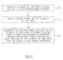
- a plurality of line pairs suitable for use in a telecommunication networkare preferably provided (step 100). Electric power is preferably supplied via the plurality of line pairs (110) and aggregated (step 120) to provide electric power suitable for powering an appliance, wherein the electric power supplied via each line pair of the plurality of line pairs does not exceed a pre-defined threshold.
Landscapes
- Engineering & Computer Science (AREA)
- Power Engineering (AREA)
- Signal Processing (AREA)
- Computer Networks & Wireless Communication (AREA)
- Supply And Distribution Of Alternating Current (AREA)
- Dc-Dc Converters (AREA)
- Telephonic Communication Services (AREA)
- Devices For Supply Of Signal Current (AREA)
- Remote Monitoring And Control Of Power-Distribution Networks (AREA)
- Data Exchanges In Wide-Area Networks (AREA)
- Cable Transmission Systems, Equalization Of Radio And Reduction Of Echo (AREA)
- Exchange Systems With Centralized Control (AREA)
Abstract
Description
Claims (13)
- A method for remote line powering in atelecommunication network comprising:characterized in that the electric power supplied via eachline pair of said plurality of line pairs does not exceed apre-defined threshold.supplying electric power via a plurality of linepairs that are suitable for use in said telecommunicationnetwork; andaggregating the electric power supplied via theplurality of line pairs to provide electric power suitablefor powering an appliance,
- The method according to claim 1 and wherein theelectric power supplied via the plurality of line pairs isobtained by feeding along each line pair in said pluralityof line pairs direct current I at an input voltage having avalue within a range from VA to VB, wherein the values ofthe current I and the input voltage are compliant withtelecommunication standards for remote feeding oftelecommunication circuits.
- The method according to claim 2, furthercomprising the step of converting each said input voltageto an output voltage aggregated to provide an aggregateoutput voltage Vout that is acceptable by saidtelecommunication standards.
- The method according to claim 2, furthercomprising the step of converting each said input voltageto an output voltage that is acceptable by saidtelecommunication standards.
- The method according to claim 3 or claim 4 andwherein each said converting step comprises the step ofconverting said input voltage to said output voltage foreach line pair independently from other line pairs in saidplurality of line pairs.
- The method according to claim 2 and wherein VA ≥50VDC, VB ≤ 320VDC, and I ≤ 60mA.
- The method according to claim 3 and wherein saidaggregate output voltage Vout is within a range of fromabout 42VDC to about 54VDC.
- Apparatus for remote line powering in atelecommunication network comprising:a plurality of line pair terminations terminatinga corresponding plurality of line pairs that are suitablefor use in said telecommunication network, the line pairsbeing operative to convey electric power supplied by acorresponding plurality of power sources; andan electric power aggregator operative toaggregate the electric power supplied via the plurality ofline pairs to provide electric power suitable for poweringan appliance, and to control that the electric powersupplied via each line pair of said plurality of line pairsdoes not exceed a pre-defined threshold.
- The apparatus according to claim 8 and whereinsaid electric power aggregator comprises a plurality ofseparate power supervisors, wherein each separate powersupervisor is operatively associated with a correspondingone of said plurality of line pair terminations.
- The apparatus according to claim 9 and whereinsaid electric power aggregator comprises a plurality of separate controllers, wherein each separate controller isoperatively associated with a corresponding one of saidplurality of separate power supervisors.
- The apparatus according to claim 10 and whereinsaid electric power aggregator comprises a plurality ofseparate power stage converters, wherein each power stageconverter is operatively associated with a correspondingone of said plurality of separate controllers and operativeto convert an inputted voltage having a value in the rangeof from about 50VDC to about 320VDC, to an output voltagethat is acceptable by telecommunication standards.
- The apparatus according to claim 10 and whereinsaid plurality of separate power stage converters areoperative in full electrical isolation from each other.
- The apparatus according to any of claims 8 - 12and also comprising a disconnection unit operative todetect that an output voltage Vout resulting fromaggregation of the electric power supplied via theplurality of line pairs is lower than an output voltageacceptable according to telecommunication standards.
Applications Claiming Priority (2)
| Application Number | Priority Date | Filing Date | Title |
|---|---|---|---|
| IL14880802AIL148808A0 (en) | 2002-03-21 | 2002-03-21 | Method and device for power supply in telecommunication systems |
| IL14880802 | 2002-03-21 |
Publications (2)
| Publication Number | Publication Date |
|---|---|
| EP1347607A1true EP1347607A1 (en) | 2003-09-24 |
| EP1347607B1 EP1347607B1 (en) | 2004-12-01 |
Family
ID=11075947
Family Applications (1)
| Application Number | Title | Priority Date | Filing Date |
|---|---|---|---|
| EP02077059AExpired - LifetimeEP1347607B1 (en) | 2002-03-21 | 2002-05-27 | Method and device for power supply in telecommunication systems |
Country Status (9)
| Country | Link |
|---|---|
| US (1) | US6665404B2 (en) |
| EP (1) | EP1347607B1 (en) |
| AT (1) | ATE284107T1 (en) |
| BE (1) | BE1014331A6 (en) |
| DE (2) | DE60202125T2 (en) |
| DK (1) | DK1347607T3 (en) |
| ES (1) | ES2229052T3 (en) |
| IL (1) | IL148808A0 (en) |
| NO (1) | NO325125B1 (en) |
Cited By (16)
| Publication number | Priority date | Publication date | Assignee | Title |
|---|---|---|---|---|
| WO2005046198A1 (en)* | 2003-11-07 | 2005-05-19 | Cherokee Europe Sa | Method and apparatus for remote powering using multiple subscriber lines |
| US10104610B2 (en) | 2010-10-13 | 2018-10-16 | Corning Optical Communications LLC | Local power management for remote antenna units in distributed antenna systems |
| US10257056B2 (en) | 2012-11-28 | 2019-04-09 | Corning Optical Communications LLC | Power management for distributed communication systems, and related components, systems, and methods |
| US10404099B1 (en) | 2018-02-28 | 2019-09-03 | Corning Optical Communications LLC | Intermediate power supply unit for distributing lower voltage power to remote power distribution systems |
| US10425891B2 (en) | 2010-10-13 | 2019-09-24 | Corning Optical Communications LLC | Power management for remote antenna units in distributed antenna systems |
| US10454270B2 (en) | 2010-11-24 | 2019-10-22 | Corning Optical Communicatons LLC | Power distribution module(s) capable of hot connection and/or disconnection for wireless communication systems, and related power units, components, and methods |
| US10455497B2 (en) | 2013-11-26 | 2019-10-22 | Corning Optical Communications LLC | Selective activation of communications services on power-up of a remote unit(s) in a wireless communication system (WCS) based on power consumption |
| US10658837B2 (en) | 2017-03-31 | 2020-05-19 | Corning Optical Communications LLC | Safety power disconnection for power distribution over power conductors to power consuming devices |
| US10992484B2 (en) | 2013-08-28 | 2021-04-27 | Corning Optical Communications LLC | Power management for distributed communication systems, and related components, systems, and methods |
| US11296504B2 (en) | 2010-11-24 | 2022-04-05 | Corning Optical Communications LLC | Power distribution module(s) capable of hot connection and/or disconnection for wireless communication systems, and related power units, components, and methods |
| US11381099B2 (en) | 2018-10-25 | 2022-07-05 | Corning Optical Communications LLC | Power distribution system |
| US11621776B2 (en) | 2020-07-29 | 2023-04-04 | Corning Research & Development Corporation | Systems for low power distribution in a power distribution network |
| US11791656B2 (en) | 2020-04-23 | 2023-10-17 | Corning Research & Development Corporation | Systems and methods for synchronizing subunits in a multi-unit power distribution network |
| US11855455B2 (en) | 2020-04-23 | 2023-12-26 | Corning Research & Development Corporation | Systems and methods for power start up in a multi-unit power distribution network |
| US11973343B2 (en) | 2019-08-05 | 2024-04-30 | Corning Research & Development Corporation | Safety power disconnection for power distribution over power conductors to radio communications circuits |
| US12126168B2 (en) | 2021-11-30 | 2024-10-22 | Corning Research & Development Corporation | Power distribution within a power source unit |
Families Citing this family (40)
| Publication number | Priority date | Publication date | Assignee | Title |
|---|---|---|---|---|
| US6480510B1 (en) | 1998-07-28 | 2002-11-12 | Serconet Ltd. | Local area network of serial intelligent cells |
| US6956826B1 (en) | 1999-07-07 | 2005-10-18 | Serconet Ltd. | Local area network for distributing data communication, sensing and control signals |
| US6690677B1 (en) | 1999-07-20 | 2004-02-10 | Serconet Ltd. | Network for telephony and data communication |
| US6549616B1 (en) | 2000-03-20 | 2003-04-15 | Serconet Ltd. | Telephone outlet for implementing a local area network over telephone lines and a local area network using such outlets |
| AT409206B (en)* | 2000-03-22 | 2002-06-25 | Ericsson Ahead Comm Systems Gm | CIRCUIT FOR THE POWER SUPPLY OF A MAINS TERMINAL UNIT |
| AU2002243623A1 (en)* | 2001-01-26 | 2002-08-06 | Regeneron Pharmaceuticals, Inc. | Methods of imaging and targeting vasculature |
| US7053501B1 (en)* | 2002-11-04 | 2006-05-30 | Cisco Technology, Inc. | Multi-pair aggregate power distribution |
| US6982860B2 (en)* | 2002-11-13 | 2006-01-03 | Adtran, Inc. | Technique for fault isolation and transient load isolation for multiple electrical loads connected to a common electrical power source |
| IL154234A (en) | 2003-01-30 | 2010-12-30 | Mosaid Technologies Inc | Method and system for providing dc power on local telephone lines |
| US7259474B2 (en)* | 2003-04-09 | 2007-08-21 | Utstarcom, Inc. | Method and apparatus for aggregating power from multiple sources |
| US7339885B2 (en)* | 2003-06-05 | 2008-03-04 | International Business Machines Corporation | Method and apparatus for customizable surveillance of network interfaces |
| US7027594B2 (en)* | 2003-06-30 | 2006-04-11 | Qwest Communications International, Inc. | System and method for cooling of network interface device |
| US7299368B2 (en)* | 2003-10-16 | 2007-11-20 | Microsemi Corp.-Analog Mixed Signal Group Ltd. | High power architecture for power over Ethernet |
| US7492059B2 (en)* | 2003-10-16 | 2009-02-17 | Microsemi Corp.—Analog Mixed Signal Group Ltd. | High power architecture for power over ethernet |
| IL159838A0 (en) | 2004-01-13 | 2004-06-20 | Yehuda Binder | Information device |
| US7449796B2 (en)* | 2004-01-22 | 2008-11-11 | Microsemi Corp. - Analog Mixed Signal Group Ltd. | Power over ethernet controller suitable for multiple modes |
| US7509114B2 (en) | 2004-01-22 | 2009-03-24 | Microsemi Corp. - Analog Mixed Signal Group Ltd. | Redundant powered device circuit |
| US20050220021A1 (en)* | 2004-04-02 | 2005-10-06 | Sosnowski John D | Methods and arrangement for power transmission over telephone lines |
| EP1617685A2 (en)* | 2004-07-15 | 2006-01-18 | ECI Telecom Ltd. | Upgrading a telecommunication street cabinet |
| US20060034180A1 (en)* | 2004-07-30 | 2006-02-16 | David Gellerman | Cable adapter port module |
| US7580732B2 (en)* | 2004-10-05 | 2009-08-25 | Spirent Communications Of Rockville, Inc. | Subscriber aggregated power |
| US7827418B2 (en)* | 2005-01-25 | 2010-11-02 | Linear Technology Corporation | Controlling power distribution among multiple wires in communication cable |
| US7508297B2 (en)* | 2005-02-11 | 2009-03-24 | Ortronics, Inc. | Apparatus and method for communication system |
| US7280032B2 (en)* | 2005-02-11 | 2007-10-09 | Ortronics, Inc. | Apparatus and method for communication system |
| US7484109B2 (en)* | 2005-03-31 | 2009-01-27 | Microsemi Corp. - Analog Mixed Signal Group Ltd. | Computer volatile memory power backup system |
| US20060242458A1 (en)* | 2005-03-31 | 2006-10-26 | Daniel Feldman | Computer volatile memory power backup system |
| US7672448B2 (en)* | 2005-06-23 | 2010-03-02 | 2Wire, Inc. | Network interface device with a remote power source |
| US7526034B2 (en)* | 2006-04-18 | 2009-04-28 | 2Wire, Inc. | Method and apparatus for communicating between devices having no common electrical ground |
| US7965977B2 (en)* | 2006-04-18 | 2011-06-21 | 2Wire, Inc. | Remote antenna system |
| US8520835B2 (en)* | 2006-04-18 | 2013-08-27 | 2Wire, Inc. | Method and apparatus for providing power to a network interface device via telephone lines |
| US9705325B2 (en)* | 2006-06-01 | 2017-07-11 | Linear Technology Corporation | Controlling switching circuits to balance power or current drawn from multiple power supply inputs |
| US8121178B2 (en)* | 2006-09-28 | 2012-02-21 | At&T Intellectual Property I, Lp | Method and system for sending data using a very high bit rate digital subscriber line |
| US8853885B2 (en)* | 2008-12-31 | 2014-10-07 | Linear Technology Corporation | Method and system for voltage independent power supply load sharing |
| US8411696B1 (en) | 2009-07-17 | 2013-04-02 | Adtran, Inc. | Systems and methods for communicating with multiple distribution points of a network |
| US8247924B1 (en)* | 2010-01-04 | 2012-08-21 | Adtran, Inc. | Power supply and method that maintains supply voltage in communications systems during a power supply interruption |
| IL210374A0 (en) | 2010-12-30 | 2011-03-31 | Eci Telecom Ltd | Technique for remote power feeding in access networks |
| WO2015139036A1 (en)* | 2014-03-14 | 2015-09-17 | Adtran, Inc. | Systems and methods for providing back power to a service unit |
| WO2016067295A1 (en)* | 2014-10-30 | 2016-05-06 | Spondoolies Tech Ltd. | Method and system for reducing power consumption in bitcoin mining via waterfall structure |
| US9473241B1 (en)* | 2015-07-06 | 2016-10-18 | Adtran, Inc. | Systems and methods for controlling the connectivity of a drop connection |
| US11394294B2 (en) | 2019-11-25 | 2022-07-19 | Corning Research & Development Corporation | Systems and methods for alternating current (AC) input selection for power transformer |
Citations (3)
| Publication number | Priority date | Publication date | Assignee | Title |
|---|---|---|---|---|
| WO2000013070A1 (en)* | 1998-08-27 | 2000-03-09 | Serconet Ltd. | Communications and control network having multiple power supplies |
| WO2000033488A1 (en)* | 1998-11-30 | 2000-06-08 | Qwest Communications International Inc. | Fiber to the curb and fiber to the neighborhood power architecture |
| WO2002035906A2 (en)* | 2000-11-01 | 2002-05-10 | Actelis Networks Ltd. | High speed access system over copper cable plant |
Family Cites Families (8)
| Publication number | Priority date | Publication date | Assignee | Title |
|---|---|---|---|---|
| US4381427A (en)* | 1981-06-16 | 1983-04-26 | Northern Telecom Limited | Subscriber loop system for voice and data |
| DE3638035A1 (en) | 1986-11-07 | 1988-05-11 | Siemens Ag | SWITCH-OFF DEVICE FOR A REGULATED POWER SUPPLY DEVICE |
| FR2720559B1 (en) | 1994-05-31 | 1996-07-05 | Alcatel Converters | Synchronization device for a secure power system. |
| US5774316A (en)* | 1996-08-26 | 1998-06-30 | Adtran, Inc. | Ground fault detector for line-powered telephone network |
| IL121643A (en) | 1997-08-27 | 2000-07-16 | Eci Telecom Ltd | Apparatus and method for concurrent voice and data transmission |
| US6584197B1 (en)* | 1998-12-03 | 2003-06-24 | Adtran Inc. | Power-limited remote termination converter with wetting current and emergency power operation for digital data transmission equipment |
| US6549570B1 (en)* | 1999-04-15 | 2003-04-15 | Cisco Technology, Inc. | Apparatus for line state analysis in a telecommunications system |
| US6282265B1 (en)* | 2000-03-07 | 2001-08-28 | Harris Corporation | Two-ended wireline pair identification system |
- 2002
- 2002-03-21ILIL14880802Apatent/IL148808A0/ennot_activeIP Right Cessation
- 2002-05-27DKDK02077059Tpatent/DK1347607T3/enactive
- 2002-05-27EPEP02077059Apatent/EP1347607B1/ennot_activeExpired - Lifetime
- 2002-05-27DEDE60202125Tpatent/DE60202125T2/ennot_activeExpired - Lifetime
- 2002-05-27ESES02077059Tpatent/ES2229052T3/ennot_activeExpired - Lifetime
- 2002-05-27ATAT02077059Tpatent/ATE284107T1/ennot_activeIP Right Cessation
- 2002-06-13USUS10/167,501patent/US6665404B2/ennot_activeExpired - Lifetime
- 2002-07-15DEDE20211597Upatent/DE20211597U1/ennot_activeExpired - Lifetime
- 2003
- 2003-02-28NONO20030935Apatent/NO325125B1/ennot_activeIP Right Cessation
- 2003-03-18BEBE2003/0170Apatent/BE1014331A6/ennot_activeIP Right Cessation
Patent Citations (3)
| Publication number | Priority date | Publication date | Assignee | Title |
|---|---|---|---|---|
| WO2000013070A1 (en)* | 1998-08-27 | 2000-03-09 | Serconet Ltd. | Communications and control network having multiple power supplies |
| WO2000033488A1 (en)* | 1998-11-30 | 2000-06-08 | Qwest Communications International Inc. | Fiber to the curb and fiber to the neighborhood power architecture |
| WO2002035906A2 (en)* | 2000-11-01 | 2002-05-10 | Actelis Networks Ltd. | High speed access system over copper cable plant |
Cited By (34)
| Publication number | Priority date | Publication date | Assignee | Title |
|---|---|---|---|---|
| AU2004307735B2 (en)* | 2003-11-07 | 2009-06-11 | MITRA Energy & Infrastructure S.A. | Method and apparatus for remote powering using multiple subscriber lines |
| WO2005046198A1 (en)* | 2003-11-07 | 2005-05-19 | Cherokee Europe Sa | Method and apparatus for remote powering using multiple subscriber lines |
| US11224014B2 (en) | 2010-10-13 | 2022-01-11 | Corning Optical Communications LLC | Power management for remote antenna units in distributed antenna systems |
| US10104610B2 (en) | 2010-10-13 | 2018-10-16 | Corning Optical Communications LLC | Local power management for remote antenna units in distributed antenna systems |
| US11178609B2 (en) | 2010-10-13 | 2021-11-16 | Corning Optical Communications LLC | Power management for remote antenna units in distributed antenna systems |
| US11671914B2 (en) | 2010-10-13 | 2023-06-06 | Corning Optical Communications LLC | Power management for remote antenna units in distributed antenna systems |
| US10420025B2 (en) | 2010-10-13 | 2019-09-17 | Corning Optical Communications LLC | Local power management for remote antenna units in distributed antenna systems |
| US10425891B2 (en) | 2010-10-13 | 2019-09-24 | Corning Optical Communications LLC | Power management for remote antenna units in distributed antenna systems |
| US11212745B2 (en) | 2010-10-13 | 2021-12-28 | Corning Optical Communications LLC | Power management for remote antenna units in distributed antenna systems |
| US11715949B2 (en) | 2010-11-24 | 2023-08-01 | Corning Optical Communications LLC | Power distribution module(s) capable of hot connection and/or disconnection for wireless communication systems, and related power units, components, and methods |
| US11296504B2 (en) | 2010-11-24 | 2022-04-05 | Corning Optical Communications LLC | Power distribution module(s) capable of hot connection and/or disconnection for wireless communication systems, and related power units, components, and methods |
| US10454270B2 (en) | 2010-11-24 | 2019-10-22 | Corning Optical Communicatons LLC | Power distribution module(s) capable of hot connection and/or disconnection for wireless communication systems, and related power units, components, and methods |
| US11114852B2 (en) | 2010-11-24 | 2021-09-07 | Corning Optical Communications LLC | Power distribution module(s) capable of hot connection and/or disconnection for wireless communication systems, and related power units, components, and methods |
| US11665069B2 (en) | 2012-11-28 | 2023-05-30 | Corning Optical Communications LLC | Power management for distributed communication systems, and related components, systems, and methods |
| US10257056B2 (en) | 2012-11-28 | 2019-04-09 | Corning Optical Communications LLC | Power management for distributed communication systems, and related components, systems, and methods |
| US10999166B2 (en) | 2012-11-28 | 2021-05-04 | Corning Optical Communications LLC | Power management for distributed communication systems, and related components, systems, and methods |
| US11516030B2 (en) | 2013-08-28 | 2022-11-29 | Corning Optical Communications LLC | Power management for distributed communication systems, and related components, systems, and methods |
| US10992484B2 (en) | 2013-08-28 | 2021-04-27 | Corning Optical Communications LLC | Power management for distributed communication systems, and related components, systems, and methods |
| US10455497B2 (en) | 2013-11-26 | 2019-10-22 | Corning Optical Communications LLC | Selective activation of communications services on power-up of a remote unit(s) in a wireless communication system (WCS) based on power consumption |
| US10658837B2 (en) | 2017-03-31 | 2020-05-19 | Corning Optical Communications LLC | Safety power disconnection for power distribution over power conductors to power consuming devices |
| US11177649B2 (en) | 2017-03-31 | 2021-11-16 | Corning Optical Communications LLC | Safety power disconnection for power distribution over power conductors to power consuming devices |
| US11121544B2 (en) | 2017-03-31 | 2021-09-14 | Corning Optical Communications LLC | Safety power disconnection for power distribution over power conductors to power consuming devices |
| US11843246B2 (en) | 2017-03-31 | 2023-12-12 | Corning Optical Communications LLC | Safety power disconnection for power distribution over power conductors to power consuming devices |
| US11412391B2 (en) | 2018-02-28 | 2022-08-09 | Corning Optical Communications LLC | Intermediate power supply unit for distributing lower voltage power to remote power distribution systems |
| US11088544B2 (en) | 2018-02-28 | 2021-08-10 | Corning Optical Communications LLC | Intermediate power supply unit for distributing lower voltage power to remote power distribution systems |
| US10404099B1 (en) | 2018-02-28 | 2019-09-03 | Corning Optical Communications LLC | Intermediate power supply unit for distributing lower voltage power to remote power distribution systems |
| US11689040B2 (en) | 2018-10-25 | 2023-06-27 | Corning Optical Communications LLC | Power distribution system |
| US11381099B2 (en) | 2018-10-25 | 2022-07-05 | Corning Optical Communications LLC | Power distribution system |
| US11973343B2 (en) | 2019-08-05 | 2024-04-30 | Corning Research & Development Corporation | Safety power disconnection for power distribution over power conductors to radio communications circuits |
| US11791656B2 (en) | 2020-04-23 | 2023-10-17 | Corning Research & Development Corporation | Systems and methods for synchronizing subunits in a multi-unit power distribution network |
| US11855455B2 (en) | 2020-04-23 | 2023-12-26 | Corning Research & Development Corporation | Systems and methods for power start up in a multi-unit power distribution network |
| US11621776B2 (en) | 2020-07-29 | 2023-04-04 | Corning Research & Development Corporation | Systems for low power distribution in a power distribution network |
| US12155416B2 (en) | 2020-07-29 | 2024-11-26 | Corning Research & Development Corporation | Systems for low power distribution in a power distribution network |
| US12126168B2 (en) | 2021-11-30 | 2024-10-22 | Corning Research & Development Corporation | Power distribution within a power source unit |
Also Published As
| Publication number | Publication date |
|---|---|
| DE20211597U1 (en) | 2002-11-21 |
| NO20030935D0 (en) | 2003-02-28 |
| EP1347607B1 (en) | 2004-12-01 |
| DE60202125D1 (en) | 2005-01-05 |
| US6665404B2 (en) | 2003-12-16 |
| NO20030935L (en) | 2003-09-22 |
| DK1347607T3 (en) | 2005-02-14 |
| DE60202125T2 (en) | 2005-04-07 |
| ES2229052T3 (en) | 2005-04-16 |
| ATE284107T1 (en) | 2004-12-15 |
| NO325125B1 (en) | 2008-02-04 |
| US20030178979A1 (en) | 2003-09-25 |
| IL148808A0 (en) | 2002-09-12 |
| BE1014331A6 (en) | 2003-08-05 |
Similar Documents
| Publication | Publication Date | Title |
|---|---|---|
| EP1347607B1 (en) | Method and device for power supply in telecommunication systems | |
| AU763004B2 (en) | Improved structure cabling system | |
| US20130214759A1 (en) | Long-distance constant-voltage electricity-feeding method with wake-up function and system | |
| ZA200106533B (en) | Improved structure cabling system. | |
| US6658108B1 (en) | System and method for distributing power over a premises network | |
| US6967585B2 (en) | Input voltage sense circuit in a line powered network element | |
| US20080265673A1 (en) | Express power load center | |
| US7113591B2 (en) | Current sense circuit in a line powered network element | |
| EP2140675B1 (en) | Remote powered node | |
| EP1764947A2 (en) | System and method for providing electrical power over communication cabling | |
| HK1059161A (en) | Method and device for power supply in telecommunication systems | |
| AU2004307735B2 (en) | Method and apparatus for remote powering using multiple subscriber lines | |
| HUT68219A (en) | Telephone system, local interface and method for supplyiwg suscriber's telephon network | |
| WO2002028111A2 (en) | Improved technique for remote power feeding of telephone subscribers | |
| US7010120B2 (en) | Method for adjusting a ringing signal current in a subscriber line and circuit arrangement | |
| AU2003248011B2 (en) | Improved Structure Cabling System |
Legal Events
| Date | Code | Title | Description |
|---|---|---|---|
| PUAI | Public reference made under article 153(3) epc to a published international application that has entered the european phase | Free format text:ORIGINAL CODE: 0009012 | |
| 17P | Request for examination filed | Effective date:20030414 | |
| AK | Designated contracting states | Kind code of ref document:A1 Designated state(s):AT BE CH CY DE DK ES FI FR GB GR IE IT LI LU MC NL PT SE TR | |
| AX | Request for extension of the european patent | Extension state:AL LT LV MK RO SI | |
| AKX | Designation fees paid | Designated state(s):AT BE CH CY DE DK ES FI FR GB GR IE IT LI LU MC NL PT SE TR | |
| REG | Reference to a national code | Ref country code:HK Ref legal event code:DE Ref document number:1059161 Country of ref document:HK | |
| GRAP | Despatch of communication of intention to grant a patent | Free format text:ORIGINAL CODE: EPIDOSNIGR1 | |
| GRAS | Grant fee paid | Free format text:ORIGINAL CODE: EPIDOSNIGR3 | |
| GRAA | (expected) grant | Free format text:ORIGINAL CODE: 0009210 | |
| AK | Designated contracting states | Kind code of ref document:B1 Designated state(s):AT BE CH CY DE DK ES FI FR GB GR IE IT LI LU MC NL PT SE TR | |
| PG25 | Lapsed in a contracting state [announced via postgrant information from national office to epo] | Ref country code:FI Free format text:LAPSE BECAUSE OF FAILURE TO SUBMIT A TRANSLATION OF THE DESCRIPTION OR TO PAY THE FEE WITHIN THE PRESCRIBED TIME-LIMIT Effective date:20041201 Ref country code:TR Free format text:LAPSE BECAUSE OF FAILURE TO SUBMIT A TRANSLATION OF THE DESCRIPTION OR TO PAY THE FEE WITHIN THE PRESCRIBED TIME-LIMIT Effective date:20041201 | |
| REG | Reference to a national code | Ref country code:GB Ref legal event code:FG4D | |
| REG | Reference to a national code | Ref country code:SE Ref legal event code:TRGR | |
| REG | Reference to a national code | Ref country code:CH Ref legal event code:EP | |
| REG | Reference to a national code | Ref country code:IE Ref legal event code:FG4D | |
| REG | Reference to a national code | Ref country code:CH Ref legal event code:NV Representative=s name:MICHELI & CIE INGENIEURS-CONSEILS | |
| REF | Corresponds to: | Ref document number:60202125 Country of ref document:DE Date of ref document:20050105 Kind code of ref document:P | |
| REG | Reference to a national code | Ref country code:DK Ref legal event code:T3 | |
| PG25 | Lapsed in a contracting state [announced via postgrant information from national office to epo] | Ref country code:GR Free format text:LAPSE BECAUSE OF FAILURE TO SUBMIT A TRANSLATION OF THE DESCRIPTION OR TO PAY THE FEE WITHIN THE PRESCRIBED TIME-LIMIT Effective date:20050301 | |
| REG | Reference to a national code | Ref country code:ES Ref legal event code:FG2A Ref document number:2229052 Country of ref document:ES Kind code of ref document:T3 | |
| PG25 | Lapsed in a contracting state [announced via postgrant information from national office to epo] | Ref country code:LU Free format text:LAPSE BECAUSE OF NON-PAYMENT OF DUE FEES Effective date:20050527 | |
| PG25 | Lapsed in a contracting state [announced via postgrant information from national office to epo] | Ref country code:MC Free format text:LAPSE BECAUSE OF NON-PAYMENT OF DUE FEES Effective date:20050531 | |
| PLBE | No opposition filed within time limit | Free format text:ORIGINAL CODE: 0009261 | |
| STAA | Information on the status of an ep patent application or granted ep patent | Free format text:STATUS: NO OPPOSITION FILED WITHIN TIME LIMIT | |
| ET | Fr: translation filed | ||
| 26N | No opposition filed | Effective date:20050902 | |
| PGFP | Annual fee paid to national office [announced via postgrant information from national office to epo] | Ref country code:CH Payment date:20070425 Year of fee payment:6 Ref country code:DK Payment date:20070425 Year of fee payment:6 | |
| PGFP | Annual fee paid to national office [announced via postgrant information from national office to epo] | Ref country code:CY Payment date:20070426 Year of fee payment:6 | |
| PG25 | Lapsed in a contracting state [announced via postgrant information from national office to epo] | Ref country code:PT Free format text:LAPSE BECAUSE OF NON-PAYMENT OF DUE FEES Effective date:20050501 | |
| REG | Reference to a national code | Ref country code:CH Ref legal event code:PL | |
| REG | Reference to a national code | Ref country code:DK Ref legal event code:EBP | |
| PG25 | Lapsed in a contracting state [announced via postgrant information from national office to epo] | Ref country code:LI Free format text:LAPSE BECAUSE OF NON-PAYMENT OF DUE FEES Effective date:20080531 Ref country code:CH Free format text:LAPSE BECAUSE OF NON-PAYMENT OF DUE FEES Effective date:20080531 | |
| PG25 | Lapsed in a contracting state [announced via postgrant information from national office to epo] | Ref country code:CY Free format text:LAPSE BECAUSE OF NON-PAYMENT OF DUE FEES Effective date:20080527 | |
| PG25 | Lapsed in a contracting state [announced via postgrant information from national office to epo] | Ref country code:DK Free format text:LAPSE BECAUSE OF NON-PAYMENT OF DUE FEES Effective date:20080531 | |
| PGFP | Annual fee paid to national office [announced via postgrant information from national office to epo] | Ref country code:AT Payment date:20100426 Year of fee payment:9 | |
| REG | Reference to a national code | Ref country code:HK Ref legal event code:WD Ref document number:1059161 Country of ref document:HK | |
| REG | Reference to a national code | Ref country code:AT Ref legal event code:MM01 Ref document number:284107 Country of ref document:AT Kind code of ref document:T Effective date:20110527 | |
| PG25 | Lapsed in a contracting state [announced via postgrant information from national office to epo] | Ref country code:AT Free format text:LAPSE BECAUSE OF NON-PAYMENT OF DUE FEES Effective date:20110527 | |
| PGFP | Annual fee paid to national office [announced via postgrant information from national office to epo] | Ref country code:NL Payment date:20120425 Year of fee payment:11 | |
| PGFP | Annual fee paid to national office [announced via postgrant information from national office to epo] | Ref country code:SE Payment date:20120423 Year of fee payment:11 | |
| PGFP | Annual fee paid to national office [announced via postgrant information from national office to epo] | Ref country code:IT Payment date:20120421 Year of fee payment:11 | |
| PGFP | Annual fee paid to national office [announced via postgrant information from national office to epo] | Ref country code:ES Payment date:20120508 Year of fee payment:11 | |
| PGFP | Annual fee paid to national office [announced via postgrant information from national office to epo] | Ref country code:IE Payment date:20130501 Year of fee payment:12 | |
| REG | Reference to a national code | Ref country code:NL Ref legal event code:V1 Effective date:20131201 | |
| REG | Reference to a national code | Ref country code:SE Ref legal event code:EUG | |
| PG25 | Lapsed in a contracting state [announced via postgrant information from national office to epo] | Ref country code:SE Free format text:LAPSE BECAUSE OF NON-PAYMENT OF DUE FEES Effective date:20130528 | |
| PG25 | Lapsed in a contracting state [announced via postgrant information from national office to epo] | Ref country code:NL Free format text:LAPSE BECAUSE OF NON-PAYMENT OF DUE FEES Effective date:20131201 | |
| PGFP | Annual fee paid to national office [announced via postgrant information from national office to epo] | Ref country code:FR Payment date:20140521 Year of fee payment:13 | |
| REG | Reference to a national code | Ref country code:IE Ref legal event code:MM4A | |
| PG25 | Lapsed in a contracting state [announced via postgrant information from national office to epo] | Ref country code:IE Free format text:LAPSE BECAUSE OF NON-PAYMENT OF DUE FEES Effective date:20140527 Ref country code:IT Free format text:LAPSE BECAUSE OF NON-PAYMENT OF DUE FEES Effective date:20140527 | |
| REG | Reference to a national code | Ref country code:ES Ref legal event code:FD2A Effective date:20150626 | |
| PG25 | Lapsed in a contracting state [announced via postgrant information from national office to epo] | Ref country code:ES Free format text:LAPSE BECAUSE OF NON-PAYMENT OF DUE FEES Effective date:20140528 | |
| REG | Reference to a national code | Ref country code:FR Ref legal event code:ST Effective date:20160129 | |
| PG25 | Lapsed in a contracting state [announced via postgrant information from national office to epo] | Ref country code:FR Free format text:LAPSE BECAUSE OF NON-PAYMENT OF DUE FEES Effective date:20150601 | |
| PGFP | Annual fee paid to national office [announced via postgrant information from national office to epo] | Ref country code:DE Payment date:20170420 Year of fee payment:16 Ref country code:GB Payment date:20170426 Year of fee payment:16 | |
| PGFP | Annual fee paid to national office [announced via postgrant information from national office to epo] | Ref country code:BE Payment date:20170424 Year of fee payment:16 | |
| REG | Reference to a national code | Ref country code:DE Ref legal event code:R119 Ref document number:60202125 Country of ref document:DE | |
| GBPC | Gb: european patent ceased through non-payment of renewal fee | Effective date:20180527 | |
| REG | Reference to a national code | Ref country code:BE Ref legal event code:MM Effective date:20180531 | |
| PG25 | Lapsed in a contracting state [announced via postgrant information from national office to epo] | Ref country code:GB Free format text:LAPSE BECAUSE OF NON-PAYMENT OF DUE FEES Effective date:20180527 Ref country code:DE Free format text:LAPSE BECAUSE OF NON-PAYMENT OF DUE FEES Effective date:20181201 | |
| PG25 | Lapsed in a contracting state [announced via postgrant information from national office to epo] | Ref country code:BE Free format text:LAPSE BECAUSE OF NON-PAYMENT OF DUE FEES Effective date:20180531 |