EP1346753A2 - Medical device that removably attaches to a bodily organ - Google Patents
Medical device that removably attaches to a bodily organDownload PDFInfo
- Publication number
- EP1346753A2 EP1346753A2EP03251774AEP03251774AEP1346753A2EP 1346753 A2EP1346753 A2EP 1346753A2EP 03251774 AEP03251774 AEP 03251774AEP 03251774 AEP03251774 AEP 03251774AEP 1346753 A2EP1346753 A2EP 1346753A2
- Authority
- EP
- European Patent Office
- Prior art keywords
- medical device
- energy transfer
- bodily organ
- support element
- transfer element
- Prior art date
- Legal status (The legal status is an assumption and is not a legal conclusion. Google has not performed a legal analysis and makes no representation as to the accuracy of the status listed.)
- Granted
Links
Images


Classifications
- A—HUMAN NECESSITIES
- A61—MEDICAL OR VETERINARY SCIENCE; HYGIENE
- A61N—ELECTROTHERAPY; MAGNETOTHERAPY; RADIATION THERAPY; ULTRASOUND THERAPY
- A61N7/00—Ultrasound therapy
- A61N7/02—Localised ultrasound hyperthermia
- A—HUMAN NECESSITIES
- A61—MEDICAL OR VETERINARY SCIENCE; HYGIENE
- A61B—DIAGNOSIS; SURGERY; IDENTIFICATION
- A61B18/00—Surgical instruments, devices or methods for transferring non-mechanical forms of energy to or from the body
- A61B2018/00005—Cooling or heating of the probe or tissue immediately surrounding the probe
- A61B2018/00011—Cooling or heating of the probe or tissue immediately surrounding the probe with fluids
Definitions
- the present inventionrelates, in general, to a medical device that removably attaches to a bodily organ and, more particularly, to such a medical device that transmits energy to tissue in or near the bodily organ.
- IUSintense ultrasound energy
- stabilization devices and methods developed for beating heart surgeryinclude compression and/or vacuum attachment to immobilize a portion of heart while suturing together blood vessels.
- Enclosed platforms or dome-like structures for creating a workspace for endoscopic access and visualizationhave also been devised for vein harvesting and cardiac surgery.
- electrodes that attach to the skin of the patient for diagnoses or therapy of underlying tissueare also well known. These include electromyography (EMG) electrodes for monitoring muscular activity or functional electrical stimulation (FES) electrodes for stimulating muscular contraction. These electrodes move freely with the movements of the patient, thus minimizing relative movement between the electrode and the relevant tissue.
- EMGelectromyography
- FESfunctional electrical stimulation
- IUS instruments developed for liver treatmentrequire sufficient energy to offset losses of energy through the abdominal wall and to compensate for the movement of the liver.
- An alternate approachis to introduce a therapeutic IUS energy transfer element through a small incision in the abdomen and to attach it directly to the surface of the liver, and allow the energy transfer element to "ride" with the movement of the liver during the treatment.
- a physicianwould position the IUS treatment energy transfer element on the anterior surface of the liver near a tumor with the aid of an intracorporeal, ultrasonic imaging device.
- the same imaging devicewould provide monitoring data to a control system in order to develop a "tool path" program for the energy beam focus.
- the IUS treatment energy transfer elementwould automatically ablate the tumor as the physician monitored the progress displayed on the control system.
- the IUS energy transfer elementmay be enveloped in a fluidic media such as, for example, a saline solution, having relatively the same acoustic energy transmission characteristics as the underlying tissue to provide acoustic coupling between the energy transfer element and the tissue.
- a fluidic mediasuch as, for example, a saline solution
- the IUS energy transfer elementsgenerate a significant amount of heat. Since the efficiency of the IUS energy transfer element may decrease rapidly with temperature increase, the fluidic media also serves as a coolant for the energy transfer element. Devices having a water-filled balloon attached over the IUS energy transfer element, and maintained with a fresh water flow, have been effectively devised primarily for these purposes.
- a multi-element, linear array IUS energy transfer elementtransmits acoustic energy from the energy transfer element face in an approximately two-dimensional plane, focusing at some distance away from the energy transfer element face.
- the focal depth and angular directivity within that plane of the focusmay be set by the type of acoustic lens attached to the face of the energy transfer element, or electronically controlled within certain ranges. It may also be necessary, however, to physically move the energy transfer element to position the acoustic focus.
- the energy transfer elementmay be rotated on its longitudinal axis to sweep the acoustic plane through a volume sector. It may also be vertically adjusted closer or nearer to the tissue.
- the present inventionaddresses these needs and overcomes numerous deficiencies of the prior art.
- the present inventionis a medical device for use on a bodily organ of a patient that enables diagnostic or therapeutic instrumentation to be securely positioned relative to the bodily organ.
- the medical devicegenerally comprises a concave support element, wherein the open side is removably attachable to the surface of the bodily organ, thereby defining an enclosed space adjacent to the bodily organ.
- the enclosed spaceis fluidly connected to a fluid management system for circulating a fluid inside of the enclosed space.
- the medical devicealso has an energy transfer element mounted to the concave support element.
- the energy transfer elementis positioned and oriented for transmitting energy to the bodily organ.
- the medical deviceincludes a cable for electrically connecting the energy transfer element to a control unit.
- the energy transfer elementtransmits intense ultrasound energy in a frequency range of 1-30 megahertz.
- the fluidacoustically couples the energy transfer element to the bodily organ, and the fluid also cools the energy transfer element.
- the fluid management systemincludes a vacuum source for adjustably creating an operating pressure within the enclosed space that is lower than the pressure external to the concave support element, for removably attaching the concave support element to the bodily organ.
- the medical devicehas an annular chamber circumventing the open side of the concave support element.
- the annular chamberis fluidly connected to a vacuum source for removably attaching the medical device to the bodily organ.
- the medical devicehas a plurality of hooking elements mounted on the concave support element.
- the hooking elementsare remotely operable for removably attaching the concave support element to the bodily organ.
- the medical devicealso includes remotely controllable positioning means for adjusting the position of the energy transfer element with respect to the bodily organ.
- the medical deviceincludes a controllable orienting means for adjusting the orientation of the energy transfer element with respect to the bodily organ.
- the medical deviceis collapsible into a collapsed configuration for insertion and removal through a surgical incision, and the medical device is expandable to a full configuration for attachment to a bodily organ.
- the medical devicehas a concave support element that is conformable to the shape of the bodily organ.
- the medical deviceincludes a flexible membrane attached to the open face of the concave support element.
- This flexible membranehermetically separates the enclosed space from the bodily organ when the medical device is attached to the bodily organ.
- the flexible membranepermits the bodily organ to protrude into the enclosed space when the fluid is at an operating pressure that is lower than the external pressure, thereby removably attaching the medical device to the bodily organ.
- One example of an application of the present inventionis removably attaching the medical device to the anterior surface of the liver of a patient, wherein the energy transfer element of the medical device transmits intense ultrasound energy to ablate a volume of diseased tissue within the liver.
- Figure 1is a schematic representation of an IUS device 30 introduced into a surgical patient 10 through an incision 18 and attached to an organ 12, with visualization through a laparoscope 16.
- Figure 2Ais an end view of an energy transfer element 102.
- Figure 2Bis a side view of energy transfer element 102 attached to a cable 104.
- Figure 3Ais an end view of a fluid filled balloon 106 containing energy transfer element 102 shown in Figure 2B.
- Figure 3Bis a side view of fluid filled balloon 106 containing energy transfer element 102 shown in Figure 3A.
- Figure 4Ais an end view of a first embodiment 100 of IUS device 30 shown in Figure 1.
- Figure 4Bis a side view of first embodiment 100 shown in Figure 4A, and includes a concave support element 112 containing fluid filled balloon 106 and energy transfer element 102.
- Figure 5is a sectional view taken at line 5-5 of first embodiment 100 shown in Figure 4B.
- Figure 6is a top view of a second embodiment 200 of IUS device 30 shown in Figure 1.
- Figure 7is a side view of second embodiment 200 shown in Figure 6.
- Figure 8is a sectional view taken at line 8-8 of second embodiment 200 of Figure 6, and includes an energy transfer element 202 mounted in a concave support element 212 having a plurality of projections 214.
- Figure 9is a top view of a third embodiment 300 of IUS device 30 shown in Figure 1.
- Figure 10is a side view of third embodiment 300 shown in Figure 9, showing a bellows 306 vertically extendable by a distance Z.
- Figure 11is a sectional view of third embodiment 300 taken at line 11-11 in Figure 9, and includes a volume 307 containing a fluid 108 and an annular chamber 308 connected to a vacuum source 39.
- Figure 12is a top view of a fourth embodiment 400 of IUS device 30 shown in Figure 1.
- Figure 13is a side view of fourth embodiment 400 shown in Figure 12.
- Figure 14is a sectional view of fourth embodiment 400 taken at line 14-14 of Figure 12, and includes an energy transfer element 402 rotatably mounted in a concave support element 412 with a membrane 413, and also including a vent 417 open during the inflow of fluid 108.
- Figure 15is a sectional view of fourth embodiment 400 of Figure 14, showing vent 417 closed as a hydraulic vacuum is applied to fluid 108.
- Figure 16is a top view of a fifth embodiment 500 of IUS device 30 of Figure 1, and indudes an inflatable housing 512.
- Figure 17is an end view of fifth embodiment 500 shown in Figure 16.
- Figure 18is a side view of fifth embodiment 500 shown in Figure 16.
- Figure 19is a sectional view of fifth embodiment 500 taken at line 19-19 of Figure 18.
- Figure 20is a sectional view of fifth embodiment 500 taken at line 20-20 of Figure 16, and includes an annular chamber 508 connected to a vacuum line 39.
- Figure 21is an end view of fifth embodiment 500 shown in a collapsed configuration.
- Figure 22is a side view of fifth embodiment 500 shown in a collapsed configuration.
- Figure 23is a top view of a sixth embodiment 600 of IUS device 30 shown in Figure 1, and includes a plurality of fluid chambers 614.
- Figure 24is an end view of sixth embodiment 600 shown in Figure 23.
- Figure 25is a side view of sixth embodiment 600 shown in Figure 23, shown in a straight position.
- Figure 26is a side view of sixth embodiment 600 shown in Figure 25, shown conformed to the shape of an organ 12.
- Figure 27is a bottom view of a seventh embodiment 700 of IUS device 30 shown in Figure 1.
- Figure 28is a sectional view taken at line 28-28 of seventh embodiment 700 shown in Figure 27, and includes an actuation cable 710 for actuating a plurality of hook elements 720.
- Figure 29is an end view of seventh embodiment 700 shown in Figure 28.
- Figure 30is a side view of seventh embodiment 700.
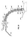
- Figure 31is an enlarged, sectional view of a portion of seventh embodiment 700 of Figure 29, showing hook element 720 in a retracted position.
- Figure 32shows hook element 720 of Figure 31 in an extended position.
- Figure 33is a sectional view taken at the curvilinear axis of a flexible shaft 800 attached to IUS device 30, wherein flexible shaft 800 includes a plurality of shaft elements 808 that are lockable into a fixed position.
- FIG 1is a schematic representation of the present invention, a medical device 30, as it may be used on a bodily organ 12 of a surgical patient 10.
- Medical device 30preferably incorporates intense ultrasound energy and is therefore also referred to as an IUS device 30.
- IUS device 30is not limited to open or endoscopic surgical procedures, but may also be used for external, non-invasive medical procedures as will be described.
- the physicianpasses IUS device 30 through an incision 18.
- the physicianmay use a laparoscope 16 through a trocar port 14 at an entry point 20 of surgical patient 10 to facilitate placement of IUS device 30 on organ 12.
- organ 12is the liver.
- a bundle 32connects IUS device 30 to a control unit 2 and a fluid management system 7, which comprises a fluid pump 4, a fluid reservoir 6, and a vacuum source 8.
- a suitable fluid pump 4is a Masterflex L/S Compact, Low-Flow, Variable Speed Drive Model No. 77200-00 coupled with a standard pump head Model No. 7016-21 having a flow capacity in the range of 2.1 to 560 ml/min.
- a suitable vacuum source 8is an Air Cadet Vacuum Pressure Pump Model No. SD-07530-40 (-508 mm Hg max vacuum) available from Cole-Parmer Instrument Company.
- General purpose laboratory vinyl tubinghaving an inner diameter in the range of approximately 1.6 to 6.4mm may be used for fluid interconnections of fluid management system 7.
- fluid management system 7is a dosed system so that fluid pressure may be adjusted to be less than atmospheric pressure.
- the partial vacuum operating pressure provided by vacuum source 7is approximately in the range of -10 to -200mm Hg.
- Bundle 32contains a control cable 34, a fluid supply line 38, and a fluid return line 36.
- Bundle 32may be flexible and permitted to lay on top of the supine, draped patient, and perhaps taped to surgical patient 10 near incision 18. Segmental portions of bundle 32 may also be rigid or semi-rigid to aid the physician in placement of IUS device 30 on organ 12. The physician may also use readily available ancillary devices not shown to support and hold bundle 32 during the procedure, as long as IUS device 30 is permitted to move freely with the movement of organ 12.
- a fluid output line 40fluidly connects fluid reservoir 6 to fluid pump 7.
- a vacuum line 42fluidly connects vacuum source 8 to fluid reservoir 6.
- control unit 2 of Figure 1controls the transmission of IUS energy from energy transfer element 102 and performs automated control of IUS focal depth and directivity.
- Control unit 2generally comprises a function generator with operator-controlled activation, a power amplifier, and an electrical matching network.
- a suitable function generatoris Hewlett Packard Corporation Model No. 33120A Function/Arbitrary Waveform Generator with input provided by a Wavetek 50 MHz Pulse/Function Generator Model No. 81.
- a suitable amplifieris the Amplifier Research Amplifier Model 150A 100A.
- Control unit 2may also include conventional devices for transducer characterization and feedback measurement, such as a Thruline Wattmeter Model No.
- Control unit 2may further include a host personal computer with an IEEE-488 interface to allow program-based control of function generators and other clinical/laboratory apparatuses.
- the aforementioned devicesare offered by way of example only; other devices or combinations of devices are well known by those skilled in the art for controlling the transmission of ultrasound energy from energy transfer element 102.
- FIGS 2A and 2Bshow a generic representation of an energy transfer element 102, which transmits energy from a face 103.
- energy transfer element 102transmits intense ultrasonic energy and has approximately a 10mm square by 50mm long cylindrical shape. The size and shape of energy transfer element 102, however, may vary significantly. Energy transfer element 102 may also have a circular or other cross sectional shape.
- Cable 104electrically connects energy transfer element 102 to control unit 2 shown in Figure 1.
- Cable 104may comprise, for example, a single bundle containing a plurality of wires. Cable 104 may alternately comprise a plurality of separated wires or a ribbon cable containing a plurality of wires so that cable 104 is relatively flexible.
- Energy transfer element 102contains one or more piezoelectric elements, which may be arranged in any one of the various arrays that are well known in the art. Energy transfer element 102 may also include various combinations of matching layers, absorptive layers, reflective layers, lens configurations, air gap layers, encapsulation materials, seals, and internal cooling, again as is well known in the art.
- Control unit 2controls the transmission of IUS energy from energy transfer element 102 for treating tissue, but control unit 2 may also be used with energy transfer element 102 to image tissue or to monitor the progress of tissue treatment.
- energy transfer element 102may comprise one or more radio frequency (RF) electrosurgical electrodes that are electrically connected to a conventional monopolar or bipolar RF generator. Medical device 30 then is a platform for holding the electrodes against tissue during highly controlled ablation.
- energy transfer element 102comprises an electrically induced heat element for locally warming the underlying tissue.
- energy transfer element 102may comprise an electromyography transducer for detecting electric potentials developed in underlying muscle tissue.
- FIGS 3A and 3Bshow energy transfer element 102 inside of a balloon 106 filled with a fluid 108.
- Balloon 106may be made of an elastomer such as silicone rubber, for example, which is practically transparent to IUS energy. Balloon 106 may also be made of a thin-wall plastic such as PET so that balloon 106 assumes a predetermined shaped when pressurized with fluid 108. Fluid supply line 38 and return line 36, together with cable 104, pass through a sealed neck 110 of balloon 106. Fluid 108 may be water, saline, oil, or any one of the well-known IUS coupling fluids. Circulation of fluid 108 inside of balloon 106 also cools energy transfer element 102, thus maintaining the efficiency and life of energy transfer element102 and protecting adjacent tissue.
- FIGS 4A, 4B, and 5show views of an embodiment 100 of IUS device 30 in Figure 1.
- Balloon 106 and energy transfer element 102mount inside a concave support element 112 having an open side 113.
- Concave support element 112includes a concave support element neck 114 that sealingly retains cable 104, fluid supply line 38, fluid return line 36, and a vacuum line 116 for creating a partial pneumatic vacuum inside a space 120 between balloon 106 and concave support element 112.
- Face 103 of energy transfer element 102faces downward against organ 12 in order to transmit energy through open side 113 of concave support element 112.
- vacuum line 116is connected to vacuum source 8 ( Figure 1), embodiment 100 may be attached to organ 12 as shown in Figure 5.
- Concave support element 112may be made of a rigid, biocompatible material such as injection molded polycarbonate, or may also be made of a relatively flexible, biocompatible elastomer such as a molded polyurethane rubber.
- cable 104may be rotationally mounted in concave support element neck 114 and mechanically engaged to an external rotation apparatus such as a stepper motor (not shown) inside of control unit 2 ( Figure 1), thus comprising an orientation means.
- Energy transfer element 102may then be rotated about its longitudinal axis within a limited arc sector (+/- 45 degrees for example). Rotating energy transfer element 102, together with electronically moving the IUS energy beam within a plane that contains the longitudinal axis of energy transfer element 102 and is perpendicular to face 103, allows treatment of a volume of tissue in organ 12.
- FIGS 6-8show an embodiment 200 of IUS device 30 of Figure 1.
- Embodiment 200comprises a concave support element 212, a energy transfer element 202 mounted within a energy transfer element enclosure 205 of concave support element 212 with a face 203 transmitting IUS energy toward an open side 213 that attaches to organ 12.
- Embodiment 200further comprises a cable 204, fluid supply line 38, and fluid return line 36.
- a plurality of projections 214extends from an inside surface 209 of concave support element 212 in a direction towards concave support element open side 213. Fluid supply line 38 and fluid return line 36 fluidly connect to fluid management system 7 depicted in Figure 1.
- the operatorpositions embodiment 200 onto organ 12, thus defining a space 220 between concave support element 212 and organ 12.
- the operatorthen actuates fluid management system 7 to fill space 220 with fluid 108, purging all air from space 220. Once filled with fluid 108, a hydraulic vacuum within space 220 is created when vacuum source 8 of fluid management system 7 is actuated so that embodiment 200 attaches atraumatically to organ 12.
- Projections 214prevent organ 12 from being drawn into space 220 and help to maintain communication of vacuum to the surface of organ 12 under concave support element 212.
- the operatormay then actuate control unit 2 to activate energy transfer element 202 and begin treating the tissue. When treatment of the tissue stops, the operator or control unit 2 turns off the hydraulic vacuum and the operator removes embodiment 200 from organ 12.
- Concave support element 212 and energy transfer element enclosure 205may be integrally molded as one piece from a variety of rigid or semi-rigid, biocompatible plastics or elastomers as described earlier. As shown for embodiment 200, energy transfer element enclosure 205 may easily be constructed so that energy transfer element 202 and cable 204 may be detached for cleaning, sterilization, and reuse on another patient. Concave support element 212, concave support element enclosure 205, fluid supply line 38, and fluid return line 36 are optionally disposable.
- FIGS 9-11show an embodiment 300 of IUS device 30 of Figure 1.
- Embodiment 300includes a positioning means that comprises a concave support element 312 having a bellows 306 that is extendable between a first position and a second position. This enables the operator to adjust vertically the distance between energy transfer element 302 (Figure 11) and the tissue being treated.
- a cable 304extends from energy transfer element 102 in the same axis as the direction of extension of bellows 306.
- Embodiment 300further comprises a energy transfer element 302 mounted to bellows 306 so that a face 303 of energy transfer element 302 may be positioned next to organ 12 or spaced apart from organ 12 at a desired distance.
- "z"indicates movement of bellows 306 from the first position to the second position.
- bellows 306extends to the first position as shown in Figure 11.
- a second pressurewhich is greater than the first pressure, is supplied to volume 307, bellows 306 extends to the second position as shown by the phantom lines in Figure 11.
- Intermediate positionsare possible by variation of the pressure of fluid 108 between the first and second pressures.
- Embodiment 300further comprises an annular chamber 308 that fluidly connects via vacuum line 39 to a pneumatic or hydraulic vacuum source for attaching embodiment 300 to organ 12.
- Fluid supply line 38 and fluid return line 36maintain fluid flow in volume 307 for coupling and cooling energy transfer element 302, in addition to pressurizing bellows 306.
- FIGS 12-15show an embodiment 400 of IUS device 30 of Figure 1.
- Embodiment 400comprises a concave support element 412, a cable 404 attached to a energy transfer element 402 having a face 403. Fluid supply line 38 and fluid return line 36 fluidly connect to fluid management system 7 depicted in Figure 1.
- Embodiment 400further comprises a valve 416 covering a vent 417, and a membrane 413 covering an opening 415 of concave support element 412.
- Concave support element 412is preferably made of a rigid, biocompatible plastic or a semi-rigid, biocompatible elastomer as for the previous embodiments.
- Membrane 413is made of a thin, elastic, fluid sealing material, such as silicone rubber, that is effectively transparent to the acoustic energy emitted by energy transfer element 402.
- the operatorpositions embodiment 400 onto organ 12 over the tissue to be treated and actuates fluid system 7 to fill a fluid chamber 407 defined by concave support element 412 and membrane 413 with fluid 108.
- the pressure of the air or other fluids inside of fluid chamber 407push open valve 416, which is normally closed, allowing the air or other fluids to escape through vent 417.
- the operatormay actuate fluid system 7 to create a hydraulic vacuum inside of fluid chamber 407 while firmly holding concave support element 412 against organ 12.
- Organ 12is drawn partway into fluid chamber 407 only to the extent permitted by the diaphragmatic resistance provided by membrane 413.
- membrane 413behaves much like another thin tissue layer on organ 12, and the hydraulic vacuum inside of fluid chamber 407 causes embodiment 400 to attach to organ 12 atraumatically, while still containing fluid 108.
- Variation of the hydraulic vacuum pressurealso allows adjustment of the distance between face 403 of energy transfer element 402 and organ 12.
- Embodiment 400allows the operator the option of using a fluid media for fluid 108 that the operator prefers not to spill onto organ 12 and into the body cavity. This primarily helps to conserve fluid 108 (which may contain, for example, expensive therapeutic agents) and minimizes the need for aspirating fluid from the body cavity during the procedure.
- Embodiment 400further includes a pivot block 420 projecting from concave support element 412 to support a post 424 extending from energy transfer element 402, and a neck 422 for rotationally supporting cable 404.
- Energy transfer element 402may be pivoted about its longitudinal axis, either manually or under control of control unit 2 as described earlier, in order to sweep IUS energy through organ 12.
- FIGS 16-22show an embodiment 500 of IUS device 30 of Figure 1.
- Embodiment 500comprises an inflatable housing 512, which has a full configuration ( Figures 16-20) when an interior space 507 is filled with fluid 108, and which has a collapsed configuration ( Figures 21-22) when fluid 108 and/or air have been evacuated from interior space 507.
- Fluid supply line 38 and fluid return line 36communicate fluid under the desired pressure to fluid management system 7 shown in Figure 1.
- embodiment 500When in the full configuration, embodiment 500 may be attached to organ 12 for treatment of tissue.
- embodiment 500When in the collapsed configuration, embodiment 500 may be easily passed through a minimally invasive incision in the abdominal wall of the patient, or through an appropriately sized trocar cannula, thus reducing postoperative pain and recovery time for the patient.
- Inflatable housing 512may be molded, for example, from a tough and resiliently flexible, biocompatible polymer such as polyurethane or polyethylene.
- a energy transfer element 502is attached, for example with an adhesive, to an interior surface 522 of inflatable housing 512, so that face 503 faces toward bottom side 515.
- a cable 504exits through a tight-fitting, housing neck 524.
- Embodiment 500further comprises an annular chamber 508 disposed on bottom side 515 of inflatable housing 512. Annular chamber 508 fluidly connects to a vacuum source by vacuum line 39.
- a membrane 513covers annular chamber 508 and contains a plurality of ports 520 spaced apart over annular chamber 508.
- a multiplicity of bumps 518 on annular chamber 508help to maintain vacuum communication within annular chamber 508.
- the operatorpositions embodiment 500 on organ 12 while inflatable housing 512 is inflated.
- the operatorthen may supply vacuum to annular chamber 508 to attach embodiment 500 to organ 12.
- Energy transfer element 502may next be activated to treat tissue.
- Figures 23-26show an embodiment 600 of IUS device 30 of Figure 1.
- Embodiment 600is very similar to embodiment 200 shown in Figures 6-8, except that a concave support element 612 comprises a plurality of fluid chambers 614 that fluidly communicate via common lumen 613 and that may flex relative to each other. This allows a bottom surface 616 to become non-planar as shown in Figure 26 so that embodiment 600 may easily conform to a curved portion of organ 12.
- FIGS 27-32show an embodiment 700 of IUS device 30 of Figure 1.
- Embodiment 700is also very similar to embodiment 200 shown in Figures 6-8 except that an attachment mechanism 730 is provided to further facilitate attachment of embodiment 700 to organ 12.
- Embodiment 700comprises a concave support element 712, a energy transfer element 702, a cable 704, fluid supply line 38, and fluid return line 36.
- Concave support element 712has a bottom side 713 and a fluid chamber 705.
- Attachment mechanism 730includes a plurality of hook elements 720 spaced apart and mounted on an actuation cable 710 that is rotatable about a curvilinear axis 726. Attachment mechanism 730 is outside the "field of view" of energy transfer element 702 so that energy transmitted from energy transfer element 702 to tissue passes only through fluid 108.
- hook elements 720are retractable from tissue so that the operator may slide and position embodiment 700 on organ 12.
- a peripheral shelf 722extending from an inside surface 713 of concave support element 712 supports hook elements 720.
- the operatoruses a remotely located control (not shown) to rotate actuation cable 710 as shown in Figure 32, thus rotating hook elements 720 simultaneously and penetrating the superficial tissue of organ 12.
- the hooksare approximately the same size, for example, as surgical vascular needles. The depth of penetration of the needles may be about in the range of 1-3mm. Many more or less needles than shown may be used.
- Attachment mechanism 730may be used alone or in combination with a hydraulic vacuum in fluid chamber 705 to attach embodiment 700 to organ 12. Laboratory experiments on live porcine liver show that bleeding from many tiny superficial punctures as created by hook elements 720 can be easily managed during the procedure.
- FIG 33shows a flexible shaft 800 for holding IUS device 30 of Figure 1.
- Flexible shaft 800comprises a plurality of shaft elements 808, a tensioning element 810, a tensioning mechanism 812, a fluid line 814, and a cable 804.
- IUS device 30may be embodied as any one of embodiments 200, 300, 400, 500, 600, and 700 described in the previous Figures 2-32.
- Each shaft element 808has a ball 806 and a joining concave support element 802.
- Each ball 806mates into joining concave support element 802 of adjacent shaft element 808 except for a proximal ball 807 that fits into a frame 815 of tensioning mechanism 812, and a distal joining concave support element 809 that fits onto a mount 820 attached to IUS device 30.
- Shaft elements 808are retained to each other and to housing 815 and mount 820 by tensioning element 810 passing through a lumen 816.
- Lumen 816fluidly connects to fluid line 814.
- Tensioning element 810anchors to a retaining element 822 inside of mount 820.
- a proximal end 824 of tensioning element 810attaches to a lever 817 of tensioning mechanism 812.
- lever 817When lever 817 is in a lock position, flexible shaft 800 rigidly assumes the configuration it is in.
- lever 817is in a release position, flexible shaft 800 is flexible.
- the operatormay position IUS device 30 on an organ while using the rigid configuration of flexible shaft 800 as a handle. Once the operator attaches IUS device 30 to organ 12 via any one of the embodiments disclosed herein, the operator converts flexible shaft 800 to its flexible configuration so that movement of organ 12 is not significantly hindered.
- the present inventioneffectively minimizes relative motion between an IUS energy transfer element and underlying tissue of the bodily organ, but may have applicability to other therapeutic or diagnostic energy modalities, including radio frequency electrosurgical energy, laser energy, conventional electrical heating elements, and others. Some of these energy modalities may be operable in a wireless mode, that is, without the need for electrical cables attached to the device, thus allowing the device to move even more freely with the movements of the organ. Further, the present invention has equal application in robotic-assisted surgical applications. In addition, the present invention may be useful for the administration of pharmaceutical agents or for the removal of fluids, toxins, or other substances from the patient. The present invention may be used for internal surgical procedures on various organs including the liver, stomach, and lungs, or may also be used externally and attached to the patient's skin to treat or diagnose underlying tissues.
Landscapes
- Health & Medical Sciences (AREA)
- Engineering & Computer Science (AREA)
- Biomedical Technology (AREA)
- Nuclear Medicine, Radiotherapy & Molecular Imaging (AREA)
- Radiology & Medical Imaging (AREA)
- Life Sciences & Earth Sciences (AREA)
- Animal Behavior & Ethology (AREA)
- General Health & Medical Sciences (AREA)
- Public Health (AREA)
- Veterinary Medicine (AREA)
- Surgical Instruments (AREA)
- Laser Surgery Devices (AREA)
- Percussion Or Vibration Massage (AREA)
- External Artificial Organs (AREA)
Abstract
Description
Claims (12)
- A medical device for use on a bodily organ of a patient, themedical device comprising:a) a support element having an open portion that is removablyattachable to the surface of the bodily organ, thereby defining an enclosedspace adjacent to the bodily organ; andb) an energy transfer element mounted to the support element, theenergy transfer element positioned and oriented for transmitting energy to thebodily organ.
- The medical device of claim 1, wherein the enclosed space isfluidly connected to a fluid management system for circulating a fluid inside of theenclosed space
- The medical device of claim 2, wherein the energy transferelement transmits intense ultrasound energy in a frequency range of 1-30megahertz, and the fluid acoustically couples the energy transfer element to thebodily organ.
- The medical device of claim 2, wherein the fluid managementsystem includes a vacuum source for adjustably creating an operating pressurewithin the enclosed space that is lower than the pressure external to the supportelement, for removably attaching the support element to the bodily organ.
- The medical device of claim 1 further comprising an annularchamber circumventing the open portion of the support element, the annularchamber fluidly connected to a vacuum source for removably attaching themedical device to the bodily organ.
- The medical device of claim 1 further comprising a plurality ofattachment elements mounted on the support element for removably attachingthe support element to the bodily organ.
- The medical device of claim 6, wherein the attachment elementsare hooks.
- The medical device of claim 1 further comprising positioningmeans for adjusting the position of the energy transfer element with respect tothe bodily organ.
- The medical device of claim 1, wherein the medical device iscollapsible into a collapsed configuration for insertion into a body cavity and isexpandable to a expanded configuration for attachment to a bodily organ.
- The medical device of claim 1, wherein the support element isconformable to the shape of the bodily organ.
- The medical device of claim 1, further comprising a flexiblemembrane attached to the support element and hermetically separating theenclosed space from the bodily organ.
- A method of attaching a medical device for use in treating tissuein a bodily organ, the method comprising:providing a medical device comprising a support element havingan open side adjacent to the bodily organ, thereby defining an enclosed spaceadjacent to the bodily organ;providing a fluid inside of the enclosed space; andmounting an energy transfer to the support element, the energytransfer element positioned and oriented for transmitting energy to the bodilyorgan.
Applications Claiming Priority (2)
| Application Number | Priority Date | Filing Date | Title |
|---|---|---|---|
| US10/104,606US20030181890A1 (en) | 2002-03-22 | 2002-03-22 | Medical device that removably attaches to a bodily organ |
| US104606 | 2002-03-22 |
Publications (3)
| Publication Number | Publication Date |
|---|---|
| EP1346753A2true EP1346753A2 (en) | 2003-09-24 |
| EP1346753A3 EP1346753A3 (en) | 2003-10-15 |
| EP1346753B1 EP1346753B1 (en) | 2007-06-13 |
Family
ID=27788396
Family Applications (1)
| Application Number | Title | Priority Date | Filing Date |
|---|---|---|---|
| EP03251774AExpired - LifetimeEP1346753B1 (en) | 2002-03-22 | 2003-03-21 | Medical device that removably attaches to a bodily organ |
Country Status (10)
| Country | Link |
|---|---|
| US (2) | US20030181890A1 (en) |
| EP (1) | EP1346753B1 (en) |
| JP (1) | JP2003319945A (en) |
| CN (1) | CN1494934A (en) |
| AT (1) | ATE364426T1 (en) |
| AU (1) | AU2003202412A1 (en) |
| BR (1) | BR0300689A (en) |
| CA (1) | CA2423135A1 (en) |
| DE (1) | DE60314314T2 (en) |
| MX (1) | MXPA03002590A (en) |
Cited By (19)
| Publication number | Priority date | Publication date | Assignee | Title |
|---|---|---|---|---|
| EP1602392A1 (en)* | 2004-06-01 | 2005-12-07 | Ethicon Endo-Surgery, Inc. | A surgically implantable injection port having an improved fastener |
| EP1736199A1 (en)* | 2003-12-19 | 2006-12-27 | Ethicon Endo-Surgery, Inc. | Implantable medical device with cover |
| EP1736202A1 (en)* | 2005-06-24 | 2006-12-27 | Ethicon Endo-Surgery, Inc. | Applier for implantable medical device |
| EP1922009A2 (en)* | 2005-08-12 | 2008-05-21 | Board of Regents, The University of Texas System | Systems, devices, and methods for optically clearing tissue |
| US7909804B2 (en)* | 2005-02-07 | 2011-03-22 | C. R. Bard, Inc. | Vascular access port with integral attachment mechanism |
| EP2142125A4 (en)* | 2007-04-19 | 2011-04-20 | Miramar Labs Inc | METHODS, DEVICES AND SYSTEMS FOR NON-INVASIVE ADMINISTRATION OF MICROWAVE THERAPY |
| EP2142128A4 (en)* | 2007-04-19 | 2011-04-20 | Miramar Labs Inc | SYSTEMS AND METHODS USING MICROWAVE ENERGY TO APPLY AN EFFECT ON A DETERMINED TISSUE |
| US8007479B2 (en)* | 2003-09-15 | 2011-08-30 | Allergan, Inc. | Implantable injection port |
| RU2435615C2 (en)* | 2005-06-24 | 2011-12-10 | Этикон Эндо-Серджери, Инк. | Implanted medical device with indicator |
| EP2271276A4 (en)* | 2008-04-17 | 2013-01-23 | Miramar Labs Inc | Systems, apparatus, methods and procedures for the noninvasive treatment of tissue using microwave energy |
| US8406894B2 (en) | 2007-12-12 | 2013-03-26 | Miramar Labs, Inc. | Systems, apparatus, methods and procedures for the noninvasive treatment of tissue using microwave energy |
| US8469951B2 (en) | 2011-08-01 | 2013-06-25 | Miramar Labs, Inc. | Applicator and tissue interface module for dermatological device |
| US8688228B2 (en) | 2007-04-19 | 2014-04-01 | Miramar Labs, Inc. | Systems, apparatus, methods and procedures for the noninvasive treatment of tissue using microwave energy |
| US8853600B2 (en) | 1997-07-31 | 2014-10-07 | Miramar Labs, Inc. | Method and apparatus for treating subcutaneous histological features |
| EP2349167B1 (en)* | 2008-10-22 | 2015-08-05 | Miramar Labs, Inc. | Systems for the non-invasive treatment of tissue using microwave energy |
| US9149331B2 (en) | 2007-04-19 | 2015-10-06 | Miramar Labs, Inc. | Methods and apparatus for reducing sweat production |
| US10624696B2 (en) | 2007-04-19 | 2020-04-21 | Miradry, Inc. | Systems and methods for creating an effect using microwave energy to specified tissue |
| US10779885B2 (en) | 2013-07-24 | 2020-09-22 | Miradry. Inc. | Apparatus and methods for the treatment of tissue using microwave energy |
| IT202300014091A1 (en)* | 2023-07-06 | 2025-01-06 | Scuola Superiore Di Studi Univ E Di Perfezionamento Sant’Anna | ROBOT FOR THERAPEUTIC TREATMENTS WITH FOCUSED ULTRASOUND |
Families Citing this family (119)
| Publication number | Priority date | Publication date | Assignee | Title |
|---|---|---|---|---|
| US9101765B2 (en) | 1999-03-05 | 2015-08-11 | Metacure Limited | Non-immediate effects of therapy |
| US8666495B2 (en) | 1999-03-05 | 2014-03-04 | Metacure Limited | Gastrointestinal methods and apparatus for use in treating disorders and controlling blood sugar |
| US6600953B2 (en) | 2000-12-11 | 2003-07-29 | Impulse Dynamics N.V. | Acute and chronic electrical signal therapy for obesity |
| JP4246492B2 (en) | 2001-01-05 | 2009-04-02 | メタキュアー ナームロゼ フェンノートシャップ | Regulation of eating habits |
| US20030050648A1 (en) | 2001-09-11 | 2003-03-13 | Spiration, Inc. | Removable lung reduction devices, systems, and methods |
| US6592594B2 (en) | 2001-10-25 | 2003-07-15 | Spiration, Inc. | Bronchial obstruction device deployment system and method |
| US7226448B2 (en)* | 2001-12-04 | 2007-06-05 | Estech, Inc. (Endoscopic Technologies, Inc.) | Cardiac treatment devices and methods |
| US20030181922A1 (en) | 2002-03-20 | 2003-09-25 | Spiration, Inc. | Removable anchored lung volume reduction devices and methods |
| US20030216769A1 (en) | 2002-05-17 | 2003-11-20 | Dillard David H. | Removable anchored lung volume reduction devices and methods |
| US6852108B2 (en)* | 2002-05-14 | 2005-02-08 | Spiration, Inc. | Apparatus and method for resecting and removing selected body tissue from a site inside a patient |
| US7630759B2 (en)* | 2002-05-20 | 2009-12-08 | Epi-Sci, Llc | Method and system for detecting electrophysiological changes in pre-cancerous and cancerous breast tissue and epithelium |
| US8262575B2 (en)* | 2002-05-20 | 2012-09-11 | Epi-Sci, Llc | Method and system for detecting electrophysiological changes in pre-cancerous and cancerous tissue |
| US20040152997A1 (en)* | 2002-05-20 | 2004-08-05 | Davies Richard J. | Electrophysiological approaches to assess resection and tumor ablation margins and responses to drug therapy |
| US6922586B2 (en)* | 2002-05-20 | 2005-07-26 | Richard J. Davies | Method and system for detecting electrophysiological changes in pre-cancerous and cancerous tissue |
| US7338433B2 (en)* | 2002-08-13 | 2008-03-04 | Allergan, Inc. | Remotely adjustable gastric banding method |
| DK1553878T3 (en) | 2002-08-28 | 2010-05-31 | Allergan Inc | Fatigue resistant gastric banding device |
| US7322971B2 (en) | 2003-02-07 | 2008-01-29 | Alfred E. Mann Institute For Biomedical Engineering At The University Of Southern California | Surgical drain with sensors for monitoring internal tissue condition by transmittance |
| WO2004075782A2 (en) | 2003-02-26 | 2004-09-10 | Alfred, E. Mann Institute For Biomedical Engineering At The University Of Southern California | An implantable device with sensors for differential monitoring of internal condition |
| US7100616B2 (en) | 2003-04-08 | 2006-09-05 | Spiration, Inc. | Bronchoscopic lung volume reduction method |
| US8715243B2 (en) | 2003-06-16 | 2014-05-06 | Ethicon Endo-Surgery, Inc. | Injection port applier with downward force actuation |
| US7862546B2 (en) | 2003-06-16 | 2011-01-04 | Ethicon Endo-Surgery, Inc. | Subcutaneous self attaching injection port with integral moveable retention members |
| JP4943841B2 (en) | 2003-06-20 | 2012-05-30 | メタキュアー リミティド | Gastrointestinal methods and devices for use in treating disorders |
| US8792985B2 (en) | 2003-07-21 | 2014-07-29 | Metacure Limited | Gastrointestinal methods and apparatus for use in treating disorders and controlling blood sugar |
| US7533671B2 (en) | 2003-08-08 | 2009-05-19 | Spiration, Inc. | Bronchoscopic repair of air leaks in a lung |
| JP4722850B2 (en) | 2003-09-15 | 2011-07-13 | アラーガン、インコーポレイテッド | Implantable device clamping system and method of use |
| US8162897B2 (en) | 2003-12-19 | 2012-04-24 | Ethicon Endo-Surgery, Inc. | Audible and tactile feedback |
| JP2007527279A (en) | 2004-01-23 | 2007-09-27 | アラーガン、インコーポレイテッド | One-piece adjustable gastric band that can be fixed removably |
| CA2559056A1 (en) | 2004-03-08 | 2005-09-22 | Endoart S.A. | Closure system for tubular organs |
| EP1732635B1 (en) | 2004-03-18 | 2011-07-27 | Allergan, Inc. | Apparatus for volume adjustment of intragastric balloons |
| US20050228415A1 (en)* | 2004-03-23 | 2005-10-13 | Michael Gertner | Methods and devices for percutaneous, non-laparoscopic treatment of obesity |
| US7946976B2 (en)* | 2004-03-23 | 2011-05-24 | Michael Gertner | Methods and devices for the surgical creation of satiety and biofeedback pathways |
| US7255675B2 (en)* | 2004-03-23 | 2007-08-14 | Michael Gertner | Devices and methods to treat a patient |
| WO2006049725A2 (en)* | 2004-03-23 | 2006-05-11 | Minimus Surgical Systems | Surgical systems and devices to enhance gastric restriction therapies |
| US20060195139A1 (en)* | 2004-03-23 | 2006-08-31 | Michael Gertner | Extragastric devices and methods for gastroplasty |
| JP2007537011A (en)* | 2004-05-14 | 2007-12-20 | メドトロニック・インコーポレーテッド | Method and apparatus for treating atrial fibrillation by reducing mass |
| US8612016B2 (en) | 2004-08-18 | 2013-12-17 | Metacure Limited | Monitoring, analysis, and regulation of eating habits |
| US9821158B2 (en) | 2005-02-17 | 2017-11-21 | Metacure Limited | Non-immediate effects of therapy |
| WO2006129321A2 (en) | 2005-06-02 | 2006-12-07 | Metacure N.V. | Gi lead implantation |
| WO2007080595A2 (en) | 2006-01-12 | 2007-07-19 | Metacure N.V. | Electrode assemblies, tools, and methods for gastric wall implantation |
| US8251888B2 (en) | 2005-04-13 | 2012-08-28 | Mitchell Steven Roslin | Artificial gastric valve |
| US20080009764A1 (en)* | 2005-04-21 | 2008-01-10 | Epi-Sci, Llc | Method and system for detecting electrophysiological changes in pre-cancerous and cancerous tissue and epithelium |
| CA2605428A1 (en)* | 2005-04-21 | 2006-11-02 | Epi-Sci, Llc | Method and system for detecting electrophysiological changes in pre-cancerous and cancerous tissue and epithelium |
| US7651483B2 (en) | 2005-06-24 | 2010-01-26 | Ethicon Endo-Surgery, Inc. | Injection port |
| US20070083120A1 (en)* | 2005-09-22 | 2007-04-12 | Cain Charles A | Pulsed cavitational ultrasound therapy |
| US8057408B2 (en) | 2005-09-22 | 2011-11-15 | The Regents Of The University Of Michigan | Pulsed cavitational ultrasound therapy |
| US10219815B2 (en) | 2005-09-22 | 2019-03-05 | The Regents Of The University Of Michigan | Histotripsy for thrombolysis |
| US8442841B2 (en) | 2005-10-20 | 2013-05-14 | Matacure N.V. | Patient selection method for assisting weight loss |
| US8295932B2 (en) | 2005-12-05 | 2012-10-23 | Metacure Limited | Ingestible capsule for appetite regulation |
| WO2007067632A2 (en)* | 2005-12-06 | 2007-06-14 | Epi-Sci, Llc | Method and system for detecting electrophysiological changes in pre-cancerous and cancerous tissue and epithelium |
| US20070149881A1 (en)* | 2005-12-22 | 2007-06-28 | Rabin Barry H | Ultrasonically Powered Medical Devices and Systems, and Methods and Uses Thereof |
| US8043206B2 (en) | 2006-01-04 | 2011-10-25 | Allergan, Inc. | Self-regulating gastric band with pressure data processing |
| US7798954B2 (en) | 2006-01-04 | 2010-09-21 | Allergan, Inc. | Hydraulic gastric band with collapsible reservoir |
| US8219177B2 (en) | 2006-02-16 | 2012-07-10 | Catholic Healthcare West | Method and system for performing invasive medical procedures using a surgical robot |
| EP1991121B1 (en)* | 2006-02-16 | 2014-08-06 | Globus Medical, Inc. | System utilizing radio frequency signals for tracking and improving navigation of slender instruments during insertion into the body |
| CN101433062B (en)* | 2006-03-02 | 2011-11-09 | 松下电器产业株式会社 | Portable terminal |
| US7691151B2 (en) | 2006-03-31 | 2010-04-06 | Spiration, Inc. | Articulable Anchor |
| JP6100613B2 (en)* | 2007-04-19 | 2017-03-22 | ミラマー ラブズ, インコーポレイテッド | Method and apparatus for reducing sweat production |
| AU2008341168B2 (en)* | 2007-12-11 | 2014-08-21 | Epi-Sci, Llc | Electrical bioimpedance analysis as a biomarker of breast density and/or breast cancer risk |
| SG186642A1 (en)* | 2007-12-12 | 2013-01-30 | Miramar Labs Inc | Systems, apparatus, methods and procedures for the noninvasive treatment of tissue using microwave energy |
| US8540707B2 (en)* | 2007-12-21 | 2013-09-24 | St. Jude Medical, Atrial Fibrillation Division, Inc. | Template system and methods |
| ES2442241T3 (en) | 2008-03-31 | 2014-02-10 | Applied Medical Resources Corporation | Electrosurgical system with a switching mechanism |
| US9023063B2 (en) | 2008-04-17 | 2015-05-05 | Apollo Endosurgery, Inc. | Implantable access port device having a safety cap |
| BRPI0910460A2 (en) | 2008-04-17 | 2018-02-14 | Allergan Inc | implantable access door device and fastening system |
| WO2010042493A1 (en) | 2008-10-06 | 2010-04-15 | Allergan, Inc. | Mechanical gastric band with cushions |
| US20100185049A1 (en) | 2008-10-22 | 2010-07-22 | Allergan, Inc. | Dome and screw valves for remotely adjustable gastric banding systems |
| WO2011022411A2 (en)* | 2009-08-17 | 2011-02-24 | Histosonics, Inc. | Disposable acoustic coupling medium container |
| JP5726191B2 (en)* | 2009-08-26 | 2015-05-27 | リージェンツ オブ ザ ユニバーシティー オブ ミシガン | Apparatus and method using control of bubble turbidity cavitation phenomenon during fracture of ureteral stones |
| US8506532B2 (en) | 2009-08-26 | 2013-08-13 | Allergan, Inc. | System including access port and applicator tool |
| JP5863654B2 (en) | 2009-08-26 | 2016-02-16 | リージェンツ オブ ザ ユニバーシティー オブ ミシガン | Micromanipulator control arm for therapeutic and image processing ultrasonic transducers |
| US8708979B2 (en) | 2009-08-26 | 2014-04-29 | Apollo Endosurgery, Inc. | Implantable coupling device |
| US8715158B2 (en) | 2009-08-26 | 2014-05-06 | Apollo Endosurgery, Inc. | Implantable bottom exit port |
| US8539813B2 (en) | 2009-09-22 | 2013-09-24 | The Regents Of The University Of Michigan | Gel phantoms for testing cavitational ultrasound (histotripsy) transducers |
| US8934975B2 (en) | 2010-02-01 | 2015-01-13 | Metacure Limited | Gastrointestinal electrical therapy |
| US8882728B2 (en) | 2010-02-10 | 2014-11-11 | Apollo Endosurgery, Inc. | Implantable injection port |
| US8758221B2 (en) | 2010-02-24 | 2014-06-24 | Apollo Endosurgery, Inc. | Source reservoir with potential energy for remotely adjustable gastric banding system |
| US8840541B2 (en) | 2010-02-25 | 2014-09-23 | Apollo Endosurgery, Inc. | Pressure sensing gastric banding system |
| US20110270024A1 (en) | 2010-04-29 | 2011-11-03 | Allergan, Inc. | Self-adjusting gastric band having various compliant components |
| US9028394B2 (en) | 2010-04-29 | 2015-05-12 | Apollo Endosurgery, Inc. | Self-adjusting mechanical gastric band |
| US9044298B2 (en) | 2010-04-29 | 2015-06-02 | Apollo Endosurgery, Inc. | Self-adjusting gastric band |
| US20110270021A1 (en) | 2010-04-30 | 2011-11-03 | Allergan, Inc. | Electronically enhanced access port for a fluid filled implant |
| US20110270025A1 (en) | 2010-04-30 | 2011-11-03 | Allergan, Inc. | Remotely powered remotely adjustable gastric band system |
| US8992415B2 (en) | 2010-04-30 | 2015-03-31 | Apollo Endosurgery, Inc. | Implantable device to protect tubing from puncture |
| US8517915B2 (en) | 2010-06-10 | 2013-08-27 | Allergan, Inc. | Remotely adjustable gastric banding system |
| US20120041258A1 (en) | 2010-08-16 | 2012-02-16 | Allergan, Inc. | Implantable access port system |
| US10456195B2 (en)* | 2010-08-31 | 2019-10-29 | Cook Medical Technologies Llc | Ablation overtube |
| US20120059216A1 (en) | 2010-09-07 | 2012-03-08 | Allergan, Inc. | Remotely adjustable gastric banding system |
| US20120065460A1 (en) | 2010-09-14 | 2012-03-15 | Greg Nitka | Implantable access port system |
| AU2011308509B8 (en) | 2010-10-01 | 2015-04-02 | Applied Medical Resources Corporation | Electrosurgical instrument |
| US8961393B2 (en) | 2010-11-15 | 2015-02-24 | Apollo Endosurgery, Inc. | Gastric band devices and drive systems |
| US8821373B2 (en) | 2011-05-10 | 2014-09-02 | Apollo Endosurgery, Inc. | Directionless (orientation independent) needle injection port |
| US8795241B2 (en) | 2011-05-13 | 2014-08-05 | Spiration, Inc. | Deployment catheter |
| US9144694B2 (en) | 2011-08-10 | 2015-09-29 | The Regents Of The University Of Michigan | Lesion generation through bone using histotripsy therapy without aberration correction |
| US8801597B2 (en) | 2011-08-25 | 2014-08-12 | Apollo Endosurgery, Inc. | Implantable access port with mesh attachment rivets |
| US9199069B2 (en) | 2011-10-20 | 2015-12-01 | Apollo Endosurgery, Inc. | Implantable injection port |
| US8858421B2 (en) | 2011-11-15 | 2014-10-14 | Apollo Endosurgery, Inc. | Interior needle stick guard stems for tubes |
| US9089395B2 (en) | 2011-11-16 | 2015-07-28 | Appolo Endosurgery, Inc. | Pre-loaded septum for use with an access port |
| US8876694B2 (en) | 2011-12-07 | 2014-11-04 | Apollo Endosurgery, Inc. | Tube connector with a guiding tip |
| US8961394B2 (en) | 2011-12-20 | 2015-02-24 | Apollo Endosurgery, Inc. | Self-sealing fluid joint for use with a gastric band |
| US9049783B2 (en) | 2012-04-13 | 2015-06-02 | Histosonics, Inc. | Systems and methods for obtaining large creepage isolation on printed circuit boards |
| WO2013166019A1 (en) | 2012-04-30 | 2013-11-07 | The Regents Of The University Of Michigan | Ultrasound transducer manufacturing using rapid-prototyping method |
| US20140100459A1 (en) | 2012-10-05 | 2014-04-10 | The Regents Of The University Of Michigan | Bubble-induced color doppler feedback during histotripsy |
| US11433254B2 (en)* | 2013-03-15 | 2022-09-06 | Pavel V. Efremkin | Apparatus and method for treatment of wounds and skin medical conditions at a predetermined skin area |
| WO2015003154A1 (en) | 2013-07-03 | 2015-01-08 | Histosonics, Inc. | Articulating arm limiter for cavitational ultrasound therapy system |
| EP3016594B1 (en) | 2013-07-03 | 2023-01-25 | Histosonics, Inc. | Histotripsy excitation sequences optimized for bubble cloud formation using shock scattering |
| US10780298B2 (en) | 2013-08-22 | 2020-09-22 | The Regents Of The University Of Michigan | Histotripsy using very short monopolar ultrasound pulses |
| WO2015176074A2 (en) | 2014-05-16 | 2015-11-19 | Applied Medical Resources Corporation | Electrosurgical system |
| JP6735272B2 (en) | 2014-05-30 | 2020-08-05 | アプライド メディカル リソーシーズ コーポレイション | Electrosurgical sealing and incision system |
| KR102545505B1 (en) | 2014-12-23 | 2023-06-20 | 어플라이드 메디컬 리소시스 코포레이션 | Bipolar Electrosurgical Sealers and Dividers |
| USD748259S1 (en) | 2014-12-29 | 2016-01-26 | Applied Medical Resources Corporation | Electrosurgical instrument |
| CN105879211A (en)* | 2015-01-26 | 2016-08-24 | 李明德 | Remote continuous therapeutic ultrasonic probe |
| JP6979882B2 (en) | 2015-06-24 | 2021-12-15 | ザ リージェンツ オブ ザ ユニヴァシティ オブ ミシガン | Tissue disruption therapy systems and methods for the treatment of brain tissue |
| CN106108945B (en)* | 2016-06-27 | 2017-05-24 | 杨浩 | Far-field ultrasonic probe for sonodynamic therapy |
| JP7610777B2 (en) | 2018-09-05 | 2025-01-09 | アプライド メディカル リソーシーズ コーポレイション | Electrosurgical Generator Control System |
| US11696796B2 (en) | 2018-11-16 | 2023-07-11 | Applied Medical Resources Corporation | Electrosurgical system |
| AU2019389001B2 (en) | 2018-11-28 | 2025-08-14 | Histosonics, Inc. | Histotripsy systems and methods |
| US11813485B2 (en) | 2020-01-28 | 2023-11-14 | The Regents Of The University Of Michigan | Systems and methods for histotripsy immunosensitization |
| JP2023540482A (en) | 2020-08-27 | 2023-09-25 | ザ リージェンツ オブ ザ ユニバーシティー オブ ミシガン | Ultrasonic transducer with transmitting and receiving functions for histotripsy |
| EP4608504A1 (en) | 2022-10-28 | 2025-09-03 | Histosonics, Inc. | Histotripsy systems and methods |
| WO2024159040A2 (en)* | 2023-01-26 | 2024-08-02 | Method Ai, Inc. | Organ attachment system |
Family Cites Families (29)
| Publication number | Priority date | Publication date | Assignee | Title |
|---|---|---|---|---|
| JPS4831554B1 (en)* | 1968-12-24 | 1973-09-29 | ||
| US4047532A (en)* | 1975-04-21 | 1977-09-13 | Phillips Jack L | Vacuum forcep and method of using same |
| DE3544628A1 (en)* | 1985-12-17 | 1987-06-19 | Eisenmenger Wolfgang | DEVICE FOR MECHANICALLY ACOUSTIC CONNECTION OF PRESSURE SHAFTS, ESPECIALLY OF FOCUSED SHOCK WAVES TO THE BODY OF LIVING BEINGS |
| DE3608877A1 (en)* | 1986-03-17 | 1987-09-24 | Non Invasive Therapeutic Tech | DEVICE FOR CRUSHING KIDNEY STONES BY MEANS OF SHOCK WAVES |
| JPH0323854A (en)* | 1989-06-21 | 1991-01-31 | Toshiba Corp | Shock wave therapy device and continuous wave thermal therapy device |
| JP3860227B2 (en)* | 1993-03-10 | 2006-12-20 | 株式会社東芝 | Ultrasonic therapy device used under MRI guide |
| JPH06285106A (en)* | 1993-03-30 | 1994-10-11 | Shimadzu Corp | Ultrasonic therapy equipment |
| US5727569A (en)* | 1996-02-20 | 1998-03-17 | Cardiothoracic Systems, Inc. | Surgical devices for imposing a negative pressure to fix the position of cardiac tissue during surgery |
| US5772675A (en)* | 1996-10-31 | 1998-06-30 | Chiron Vision Corporation | Positioning assembly for retaining and positioning a cornea |
| WO1998052465A1 (en)* | 1997-05-23 | 1998-11-26 | Transurgical, Inc. | Mri-guided therapeutic unit and methods |
| US5957919A (en)* | 1997-07-02 | 1999-09-28 | Laufer; Michael D. | Bleb reducer |
| US6143010A (en)* | 1997-07-18 | 2000-11-07 | Kera Vision Inc. | Corneal vacuum centering device |
| DE19745488B4 (en)* | 1997-10-15 | 2004-07-08 | Richard Wolf Gmbh | Endoscopic instrument for the therapy of the heart muscle |
| US6007499A (en)* | 1997-10-31 | 1999-12-28 | University Of Washington | Method and apparatus for medical procedures using high-intensity focused ultrasound |
| US6231585B1 (en)* | 1997-11-20 | 2001-05-15 | Medivas, Llc | Device for stabilizing a treatment site and method of use |
| DE19800416C2 (en)* | 1998-01-08 | 2002-09-19 | Storz Karl Gmbh & Co Kg | Device for the treatment of body tissue, in particular soft tissue close to the surface, by means of ultrasound |
| US6251065B1 (en)* | 1998-03-17 | 2001-06-26 | Gary S. Kochamba | Methods and apparatus for stabilizing tissue |
| US6277052B1 (en) | 1998-05-28 | 2001-08-21 | Kenneth W. Howard | Method and system for passively exercising selected portions of a human body |
| KR100302324B1 (en)* | 1998-06-26 | 2001-12-28 | 윤덕용 | Optical excitation inversion evaluation method of ferroelectric ceramics using acoustic emission technique |
| US6254595B1 (en)* | 1998-10-15 | 2001-07-03 | Intralase Corporation | Corneal aplanation device |
| US6280415B1 (en)* | 1999-03-10 | 2001-08-28 | W. Dudley Johnson | Tissue traction device |
| US6042539A (en)* | 1999-03-26 | 2000-03-28 | Ethicon Endo-Surgery, Inc. | Vacuum-actuated tissue-lifting device and method |
| EP1207788A4 (en)* | 1999-07-19 | 2009-12-09 | St Jude Medical Atrial Fibrill | Apparatus and method for ablating tissue |
| US6626855B1 (en)* | 1999-11-26 | 2003-09-30 | Therus Corpoation | Controlled high efficiency lesion formation using high intensity ultrasound |
| US6663622B1 (en)* | 2000-02-11 | 2003-12-16 | Iotek, Inc. | Surgical devices and methods for use in tissue ablation procedures |
| US6558382B2 (en)* | 2000-04-27 | 2003-05-06 | Medtronic, Inc. | Suction stabilized epicardial ablation devices |
| IL137689A0 (en)* | 2000-08-03 | 2001-10-31 | L R Res & Dev Ltd | System for enhanced chemical debridement |
| JP4667709B2 (en) | 2000-08-08 | 2011-04-13 | エルベ エレクトロメディツィン ゲーエムベーハー | High-frequency surgical high-frequency generator capable of adjusting allowable power amount and control method of allowable power |
| AU2001285238A1 (en)* | 2000-08-24 | 2002-03-04 | Timi 3 Systems, Inc. | Ultrasonic system for enhancing blood perfusion |
- 2002
- 2002-03-22USUS10/104,606patent/US20030181890A1/ennot_activeAbandoned
- 2003
- 2003-03-21ATAT03251774Tpatent/ATE364426T1/ennot_activeIP Right Cessation
- 2003-03-21DEDE60314314Tpatent/DE60314314T2/ennot_activeExpired - Lifetime
- 2003-03-21AUAU2003202412Apatent/AU2003202412A1/ennot_activeAbandoned
- 2003-03-21CACA002423135Apatent/CA2423135A1/ennot_activeAbandoned
- 2003-03-21EPEP03251774Apatent/EP1346753B1/ennot_activeExpired - Lifetime
- 2003-03-22CNCNA031286364Apatent/CN1494934A/enactivePending
- 2003-03-24BRBR0300689-1Apatent/BR0300689A/ennot_activeApplication Discontinuation
- 2003-03-24JPJP2003081063Apatent/JP2003319945A/enactivePending
- 2003-03-24MXMXPA03002590Apatent/MXPA03002590A/enunknown
- 2005
- 2005-01-10USUS11/032,288patent/US7223239B2/ennot_activeExpired - Lifetime
Cited By (49)
| Publication number | Priority date | Publication date | Assignee | Title |
|---|---|---|---|---|
| US8853600B2 (en) | 1997-07-31 | 2014-10-07 | Miramar Labs, Inc. | Method and apparatus for treating subcutaneous histological features |
| US8007479B2 (en)* | 2003-09-15 | 2011-08-30 | Allergan, Inc. | Implantable injection port |
| EP1736199A1 (en)* | 2003-12-19 | 2006-12-27 | Ethicon Endo-Surgery, Inc. | Implantable medical device with cover |
| EP1736197A1 (en)* | 2003-12-19 | 2006-12-27 | Ethicon Endo-Surgery, Inc. | Implantable medical device with simultaneous attachment mechanism |
| EP1736194A1 (en)* | 2003-12-19 | 2006-12-27 | Ethicon Endo-Surgery, Inc. | Implantable medical device with indicator for movable retention members |
| EP1736197B2 (en)† | 2003-12-19 | 2015-04-08 | Ethicon Endo-Surgery, Inc. | Implantable medical device with simultaneous attachment mechanism |
| EP2260773B2 (en)† | 2004-01-23 | 2014-08-13 | Apollo Endosurgery, Inc. | Implantable device fastening system |
| EP1602392A1 (en)* | 2004-06-01 | 2005-12-07 | Ethicon Endo-Surgery, Inc. | A surgically implantable injection port having an improved fastener |
| EP2327445A1 (en)* | 2004-06-01 | 2011-06-01 | Ethicon Endo-Surgery, Inc. | A surgically implantable injection port having an improved fastener |
| US9227045B2 (en) | 2005-02-07 | 2016-01-05 | C. R. Bard, Inc. | Vascular access port with integral attachment mechanism |
| US7909804B2 (en)* | 2005-02-07 | 2011-03-22 | C. R. Bard, Inc. | Vascular access port with integral attachment mechanism |
| US8262630B2 (en) | 2005-02-07 | 2012-09-11 | C. R. Bard, Inc. | Vascular access port with integral attachment mechanism |
| RU2435615C2 (en)* | 2005-06-24 | 2011-12-10 | Этикон Эндо-Серджери, Инк. | Implanted medical device with indicator |
| EP1736202A1 (en)* | 2005-06-24 | 2006-12-27 | Ethicon Endo-Surgery, Inc. | Applier for implantable medical device |
| CN1883403B (en)* | 2005-06-24 | 2012-08-15 | 伊西康内外科公司 | Applier for implantable medical device |
| US7918844B2 (en) | 2005-06-24 | 2011-04-05 | Ethicon Endo-Surgery, Inc. | Applier for implantable medical device |
| EP2656809A1 (en)* | 2005-08-12 | 2013-10-30 | Board Of Regents, The University Of Texas System | Systems, devices, and methods for optically clearing tissue |
| US9168388B2 (en) | 2005-08-12 | 2015-10-27 | The Board Of Regents, The University Of Texas System | System, devices, and methods for optically clearing tissue |
| EP1922009A2 (en)* | 2005-08-12 | 2008-05-21 | Board of Regents, The University of Texas System | Systems, devices, and methods for optically clearing tissue |
| US9149331B2 (en) | 2007-04-19 | 2015-10-06 | Miramar Labs, Inc. | Methods and apparatus for reducing sweat production |
| US10624696B2 (en) | 2007-04-19 | 2020-04-21 | Miradry, Inc. | Systems and methods for creating an effect using microwave energy to specified tissue |
| US8688228B2 (en) | 2007-04-19 | 2014-04-01 | Miramar Labs, Inc. | Systems, apparatus, methods and procedures for the noninvasive treatment of tissue using microwave energy |
| RU2523620C2 (en)* | 2007-04-19 | 2014-07-20 | Мирамар Лэбс,Инк. | Systems and methods for generating exposure on target tissue with using microwave energy |
| US12186015B2 (en) | 2007-04-19 | 2025-01-07 | Miradry, Inc. | Methods, devices, and systems for non-invasive delivery of microwave therapy |
| EP2142125A4 (en)* | 2007-04-19 | 2011-04-20 | Miramar Labs Inc | METHODS, DEVICES AND SYSTEMS FOR NON-INVASIVE ADMINISTRATION OF MICROWAVE THERAPY |
| EP2767308A1 (en)* | 2007-04-19 | 2014-08-20 | Miramar Labs, Inc. | Devices, and systems for non-invasive delivery of microwave therapy |
| US11419678B2 (en) | 2007-04-19 | 2022-08-23 | Miradry, Inc. | Methods, devices, and systems for non-invasive delivery of microwave therapy |
| US10779887B2 (en) | 2007-04-19 | 2020-09-22 | Miradry, Inc. | Systems and methods for creating an effect using microwave energy to specified tissue |
| US10463429B2 (en) | 2007-04-19 | 2019-11-05 | Miradry, Inc. | Methods, devices, and systems for non-invasive delivery of microwave therapy |
| US10166072B2 (en) | 2007-04-19 | 2019-01-01 | Miradry, Inc. | Systems and methods for creating an effect using microwave energy to specified tissue |
| US9427285B2 (en) | 2007-04-19 | 2016-08-30 | Miramar Labs, Inc. | Systems and methods for creating an effect using microwave energy to specified tissue |
| US8401668B2 (en) | 2007-04-19 | 2013-03-19 | Miramar Labs, Inc. | Systems and methods for creating an effect using microwave energy to specified tissue |
| US9241763B2 (en) | 2007-04-19 | 2016-01-26 | Miramar Labs, Inc. | Systems, apparatus, methods and procedures for the noninvasive treatment of tissue using microwave energy |
| EP2142128A4 (en)* | 2007-04-19 | 2011-04-20 | Miramar Labs Inc | SYSTEMS AND METHODS USING MICROWAVE ENERGY TO APPLY AN EFFECT ON A DETERMINED TISSUE |
| US8406894B2 (en) | 2007-12-12 | 2013-03-26 | Miramar Labs, Inc. | Systems, apparatus, methods and procedures for the noninvasive treatment of tissue using microwave energy |
| EP3391846A1 (en)* | 2007-12-12 | 2018-10-24 | Miramar Labs, Inc. | Systems, apparatus, methods and procedures for the noninvasive treatment of tissue using microwave energy |
| EP2762199A1 (en)* | 2007-12-12 | 2014-08-06 | Miramar Labs, Inc. | Systems, apparatus, methods and procedures for the noninvasive treatment of tissue using microwave energy |
| US8825176B2 (en) | 2007-12-12 | 2014-09-02 | Miramar Labs, Inc. | Apparatus for the noninvasive treatment of tissue using microwave energy |
| EP2271276A4 (en)* | 2008-04-17 | 2013-01-23 | Miramar Labs Inc | Systems, apparatus, methods and procedures for the noninvasive treatment of tissue using microwave energy |
| EP2349167B1 (en)* | 2008-10-22 | 2015-08-05 | Miramar Labs, Inc. | Systems for the non-invasive treatment of tissue using microwave energy |
| US11123136B2 (en) | 2011-08-01 | 2021-09-21 | Miradry, Inc. | Applicator and tissue interface module for dermatological device |
| US9314301B2 (en) | 2011-08-01 | 2016-04-19 | Miramar Labs, Inc. | Applicator and tissue interface module for dermatological device |
| US8469951B2 (en) | 2011-08-01 | 2013-06-25 | Miramar Labs, Inc. | Applicator and tissue interface module for dermatological device |
| US8535302B2 (en) | 2011-08-01 | 2013-09-17 | Miramar Labs, Inc. | Applicator and tissue interface module for dermatological device |
| US10321954B2 (en) | 2011-08-01 | 2019-06-18 | Miradry, Inc. | Applicator and tissue interface module for dermatological device |
| US9028477B2 (en) | 2011-08-01 | 2015-05-12 | Miramar Labs, Inc. | Applicator and tissue interface module for dermatological device |
| US10779885B2 (en) | 2013-07-24 | 2020-09-22 | Miradry. Inc. | Apparatus and methods for the treatment of tissue using microwave energy |
| IT202300014091A1 (en)* | 2023-07-06 | 2025-01-06 | Scuola Superiore Di Studi Univ E Di Perfezionamento Sant’Anna | ROBOT FOR THERAPEUTIC TREATMENTS WITH FOCUSED ULTRASOUND |
| WO2025008716A1 (en)* | 2023-07-06 | 2025-01-09 | Scuola Superiore Di Studi Universitari E Di Perfezionamento Sant'anna | Robot for focused ultrasound therapeutic treatments |
Also Published As
| Publication number | Publication date |
|---|---|
| US7223239B2 (en) | 2007-05-29 |
| BR0300689A (en) | 2004-09-08 |
| CA2423135A1 (en) | 2003-09-22 |
| DE60314314D1 (en) | 2007-07-26 |
| EP1346753B1 (en) | 2007-06-13 |
| AU2003202412A1 (en) | 2003-10-16 |
| DE60314314T2 (en) | 2008-02-21 |
| CN1494934A (en) | 2004-05-12 |
| ATE364426T1 (en) | 2007-07-15 |
| JP2003319945A (en) | 2003-11-11 |
| US20030181890A1 (en) | 2003-09-25 |
| EP1346753A3 (en) | 2003-10-15 |
| US20050148856A1 (en) | 2005-07-07 |
| MXPA03002590A (en) | 2004-12-03 |
Similar Documents
| Publication | Publication Date | Title |
|---|---|---|
| EP1346753B1 (en) | Medical device that removably attaches to a bodily organ | |
| US5762066A (en) | Multifaceted ultrasound transducer probe system and methods for its use | |
| US7135029B2 (en) | Ultrasonic surgical instrument for intracorporeal sonodynamic therapy | |
| EP2268361B1 (en) | Percutaneous probe | |
| US6361531B1 (en) | Focused ultrasound ablation devices having malleable handle shafts and methods of using the same | |
| US20120035473A1 (en) | Laparoscopic hifu probe | |
| JP2004532686A (en) | Deployable ultrasound therapy transducer | |
| CN1816308A (en) | Method and device for non-invasive treatment of atrial fibrillation using high-intensity focused ultrasound | |
| AU2002316433A1 (en) | An ultrasonic surgical instrument for intracorporeal sonodynamic therapy | |
| JP2021526913A (en) | Deployable Tyne Tissue Ablation System | |
| US20240285978A1 (en) | Minimally invasive histotripsy systems and methods | |
| EP3752084B1 (en) | Energy delivery device | |
| JP7314147B2 (en) | Systems and methods for energy delivery | |
| JP2025527304A (en) | Lung treatment | |
| JP4481600B2 (en) | Energy therapy device | |
| HK40043270B (en) | Energy delivery device | |
| HK40043270A (en) | Energy delivery device |
Legal Events
| Date | Code | Title | Description |
|---|---|---|---|
| PUAI | Public reference made under article 153(3) epc to a published international application that has entered the european phase | Free format text:ORIGINAL CODE: 0009012 | |
| PUAL | Search report despatched | Free format text:ORIGINAL CODE: 0009013 | |
| AK | Designated contracting states | Kind code of ref document:A2 Designated state(s):AT BE BG CH CY CZ DE DK EE ES FI FR GB GR HU IE IT LI LU MC NL PT RO SE SI SK TR | |
| AX | Request for extension of the european patent | Extension state:AL LT LV MK | |
| AK | Designated contracting states | Kind code of ref document:A3 Designated state(s):AT BE BG CH CY CZ DE DK EE ES FI FR GB GR HU IE IT LI LU MC NL PT RO SE SI SK TR | |
| AX | Request for extension of the european patent | Extension state:AL LT LV MK | |
| 17P | Request for examination filed | Effective date:20040326 | |
| AKX | Designation fees paid | Designated state(s):AT BE BG CH CY CZ DE DK EE ES FI FR GB GR HU IE IT LI LU MC NL PT RO SE SI SK TR | |
| 17Q | First examination report despatched | Effective date:20040818 | |
| GRAP | Despatch of communication of intention to grant a patent | Free format text:ORIGINAL CODE: EPIDOSNIGR1 | |
| GRAS | Grant fee paid | Free format text:ORIGINAL CODE: EPIDOSNIGR3 | |
| GRAA | (expected) grant | Free format text:ORIGINAL CODE: 0009210 | |
| AK | Designated contracting states | Kind code of ref document:B1 Designated state(s):AT BE BG CH CY CZ DE DK EE ES FI FR GB GR HU IE IT LI LU MC NL PT RO SE SI SK TR | |
| REG | Reference to a national code | Ref country code:GB Ref legal event code:FG4D | |
| REG | Reference to a national code | Ref country code:CH Ref legal event code:EP | |
| REG | Reference to a national code | Ref country code:IE Ref legal event code:FG4D | |
| REF | Corresponds to: | Ref document number:60314314 Country of ref document:DE Date of ref document:20070726 Kind code of ref document:P | |
| PG25 | Lapsed in a contracting state [announced via postgrant information from national office to epo] | Ref country code:SE Free format text:LAPSE BECAUSE OF FAILURE TO SUBMIT A TRANSLATION OF THE DESCRIPTION OR TO PAY THE FEE WITHIN THE PRESCRIBED TIME-LIMIT Effective date:20070913 | |
| REG | Reference to a national code | Ref country code:CH Ref legal event code:NV Representative=s name:E. BLUM & CO. AG PATENT- UND MARKENANWAELTE VSP | |
| ET | Fr: translation filed | ||
| PG25 | Lapsed in a contracting state [announced via postgrant information from national office to epo] | Ref country code:AT Free format text:LAPSE BECAUSE OF FAILURE TO SUBMIT A TRANSLATION OF THE DESCRIPTION OR TO PAY THE FEE WITHIN THE PRESCRIBED TIME-LIMIT Effective date:20070613 | |
| NLV1 | Nl: lapsed or annulled due to failure to fulfill the requirements of art. 29p and 29m of the patents act | ||
| PG25 | Lapsed in a contracting state [announced via postgrant information from national office to epo] | Ref country code:BE Free format text:LAPSE BECAUSE OF FAILURE TO SUBMIT A TRANSLATION OF THE DESCRIPTION OR TO PAY THE FEE WITHIN THE PRESCRIBED TIME-LIMIT Effective date:20070613 | |
| PG25 | Lapsed in a contracting state [announced via postgrant information from national office to epo] | Ref country code:NL Free format text:LAPSE BECAUSE OF FAILURE TO SUBMIT A TRANSLATION OF THE DESCRIPTION OR TO PAY THE FEE WITHIN THE PRESCRIBED TIME-LIMIT Effective date:20070613 Ref country code:PT Free format text:LAPSE BECAUSE OF FAILURE TO SUBMIT A TRANSLATION OF THE DESCRIPTION OR TO PAY THE FEE WITHIN THE PRESCRIBED TIME-LIMIT Effective date:20071113 Ref country code:SI Free format text:LAPSE BECAUSE OF FAILURE TO SUBMIT A TRANSLATION OF THE DESCRIPTION OR TO PAY THE FEE WITHIN THE PRESCRIBED TIME-LIMIT Effective date:20070613 Ref country code:ES Free format text:LAPSE BECAUSE OF FAILURE TO SUBMIT A TRANSLATION OF THE DESCRIPTION OR TO PAY THE FEE WITHIN THE PRESCRIBED TIME-LIMIT Effective date:20070924 Ref country code:CZ Free format text:LAPSE BECAUSE OF FAILURE TO SUBMIT A TRANSLATION OF THE DESCRIPTION OR TO PAY THE FEE WITHIN THE PRESCRIBED TIME-LIMIT Effective date:20070613 Ref country code:BG Free format text:LAPSE BECAUSE OF FAILURE TO SUBMIT A TRANSLATION OF THE DESCRIPTION OR TO PAY THE FEE WITHIN THE PRESCRIBED TIME-LIMIT Effective date:20070913 | |
| PG25 | Lapsed in a contracting state [announced via postgrant information from national office to epo] | Ref country code:SK Free format text:LAPSE BECAUSE OF FAILURE TO SUBMIT A TRANSLATION OF THE DESCRIPTION OR TO PAY THE FEE WITHIN THE PRESCRIBED TIME-LIMIT Effective date:20070613 | |
| PLBE | No opposition filed within time limit | Free format text:ORIGINAL CODE: 0009261 | |
| STAA | Information on the status of an ep patent application or granted ep patent | Free format text:STATUS: NO OPPOSITION FILED WITHIN TIME LIMIT | |
| PG25 | Lapsed in a contracting state [announced via postgrant information from national office to epo] | Ref country code:DK Free format text:LAPSE BECAUSE OF FAILURE TO SUBMIT A TRANSLATION OF THE DESCRIPTION OR TO PAY THE FEE WITHIN THE PRESCRIBED TIME-LIMIT Effective date:20070613 Ref country code:GR Free format text:LAPSE BECAUSE OF FAILURE TO SUBMIT A TRANSLATION OF THE DESCRIPTION OR TO PAY THE FEE WITHIN THE PRESCRIBED TIME-LIMIT Effective date:20070914 | |
| 26N | No opposition filed | Effective date:20080314 | |
| PG25 | Lapsed in a contracting state [announced via postgrant information from national office to epo] | Ref country code:RO Free format text:LAPSE BECAUSE OF FAILURE TO SUBMIT A TRANSLATION OF THE DESCRIPTION OR TO PAY THE FEE WITHIN THE PRESCRIBED TIME-LIMIT Effective date:20070613 | |
| PG25 | Lapsed in a contracting state [announced via postgrant information from national office to epo] | Ref country code:MC Free format text:LAPSE BECAUSE OF NON-PAYMENT OF DUE FEES Effective date:20080331 | |
| REG | Reference to a national code | Ref country code:CH Ref legal event code:PL | |
| PG25 | Lapsed in a contracting state [announced via postgrant information from national office to epo] | Ref country code:LI Free format text:LAPSE BECAUSE OF NON-PAYMENT OF DUE FEES Effective date:20080331 Ref country code:EE Free format text:LAPSE BECAUSE OF FAILURE TO SUBMIT A TRANSLATION OF THE DESCRIPTION OR TO PAY THE FEE WITHIN THE PRESCRIBED TIME-LIMIT Effective date:20070613 Ref country code:CH Free format text:LAPSE BECAUSE OF NON-PAYMENT OF DUE FEES Effective date:20080331 Ref country code:IE Free format text:LAPSE BECAUSE OF NON-PAYMENT OF DUE FEES Effective date:20080321 | |
| PG25 | Lapsed in a contracting state [announced via postgrant information from national office to epo] | Ref country code:FI Free format text:LAPSE BECAUSE OF FAILURE TO SUBMIT A TRANSLATION OF THE DESCRIPTION OR TO PAY THE FEE WITHIN THE PRESCRIBED TIME-LIMIT Effective date:20070613 | |
| PG25 | Lapsed in a contracting state [announced via postgrant information from national office to epo] | Ref country code:CY Free format text:LAPSE BECAUSE OF FAILURE TO SUBMIT A TRANSLATION OF THE DESCRIPTION OR TO PAY THE FEE WITHIN THE PRESCRIBED TIME-LIMIT Effective date:20070613 | |
| PG25 | Lapsed in a contracting state [announced via postgrant information from national office to epo] | Ref country code:LU Free format text:LAPSE BECAUSE OF NON-PAYMENT OF DUE FEES Effective date:20080321 Ref country code:HU Free format text:LAPSE BECAUSE OF FAILURE TO SUBMIT A TRANSLATION OF THE DESCRIPTION OR TO PAY THE FEE WITHIN THE PRESCRIBED TIME-LIMIT Effective date:20071214 | |
| PG25 | Lapsed in a contracting state [announced via postgrant information from national office to epo] | Ref country code:TR Free format text:LAPSE BECAUSE OF FAILURE TO SUBMIT A TRANSLATION OF THE DESCRIPTION OR TO PAY THE FEE WITHIN THE PRESCRIBED TIME-LIMIT Effective date:20070613 | |
| REG | Reference to a national code | Ref country code:FR Ref legal event code:PLFP Year of fee payment:14 | |
| REG | Reference to a national code | Ref country code:FR Ref legal event code:PLFP Year of fee payment:15 | |
| REG | Reference to a national code | Ref country code:FR Ref legal event code:PLFP Year of fee payment:16 | |
| PGFP | Annual fee paid to national office [announced via postgrant information from national office to epo] | Ref country code:GB Payment date:20190320 Year of fee payment:17 Ref country code:DE Payment date:20190305 Year of fee payment:17 Ref country code:IT Payment date:20190326 Year of fee payment:17 | |
| PGFP | Annual fee paid to national office [announced via postgrant information from national office to epo] | Ref country code:FR Payment date:20190213 Year of fee payment:17 | |
| REG | Reference to a national code | Ref country code:DE Ref legal event code:R119 Ref document number:60314314 Country of ref document:DE | |
| PG25 | Lapsed in a contracting state [announced via postgrant information from national office to epo] | Ref country code:FR Free format text:LAPSE BECAUSE OF NON-PAYMENT OF DUE FEES Effective date:20200331 Ref country code:DE Free format text:LAPSE BECAUSE OF NON-PAYMENT OF DUE FEES Effective date:20201001 | |
| GBPC | Gb: european patent ceased through non-payment of renewal fee | Effective date:20200321 | |
| PG25 | Lapsed in a contracting state [announced via postgrant information from national office to epo] | Ref country code:GB Free format text:LAPSE BECAUSE OF NON-PAYMENT OF DUE FEES Effective date:20200321 | |
| PG25 | Lapsed in a contracting state [announced via postgrant information from national office to epo] | Ref country code:IT Free format text:LAPSE BECAUSE OF NON-PAYMENT OF DUE FEES Effective date:20200321 |