EP1346483B1 - Communication device with multiple detachable communication modules - Google Patents
Communication device with multiple detachable communication modulesDownload PDFInfo
- Publication number
- EP1346483B1 EP1346483B1EP01993981.8AEP01993981AEP1346483B1EP 1346483 B1EP1346483 B1EP 1346483B1EP 01993981 AEP01993981 AEP 01993981AEP 1346483 B1EP1346483 B1EP 1346483B1
- Authority
- EP
- European Patent Office
- Prior art keywords
- communication module
- communication
- module
- cavity
- terminals
- Prior art date
- Legal status (The legal status is an assumption and is not a legal conclusion. Google has not performed a legal analysis and makes no representation as to the accuracy of the status listed.)
- Expired - Lifetime
Links
- 238000004891communicationMethods0.000titleclaimsdescription293
- 230000001413cellular effectEffects0.000description11
- 230000006870functionEffects0.000description9
- 230000014759maintenance of locationEffects0.000description6
- 238000000034methodMethods0.000description4
- 230000001681protective effectEffects0.000description4
- 238000010295mobile communicationMethods0.000description3
- 230000001419dependent effectEffects0.000description2
- 238000013461designMethods0.000description2
- 238000010586diagramMethods0.000description2
- 238000003780insertionMethods0.000description2
- 230000037431insertionEffects0.000description2
- 239000000463materialSubstances0.000description2
- 238000003032molecular dockingMethods0.000description2
- 238000012544monitoring processMethods0.000description2
- 230000005236sound signalEffects0.000description2
- 230000036772blood pressureEffects0.000description1
- 238000006243chemical reactionMethods0.000description1
- 238000007599dischargingMethods0.000description1
- 230000005484gravityEffects0.000description1
- 238000007373indentationMethods0.000description1
- 238000009434installationMethods0.000description1
- 230000013011matingEffects0.000description1
- 230000000474nursing effectEffects0.000description1
- 230000002093peripheral effectEffects0.000description1
- 230000035755proliferationEffects0.000description1
- 230000035485pulse pressureEffects0.000description1
- 230000000717retained effectEffects0.000description1
- 230000001953sensory effectEffects0.000description1
- 230000007704transitionEffects0.000description1
- 239000012780transparent materialSubstances0.000description1
Images


Classifications
- H—ELECTRICITY
- H04—ELECTRIC COMMUNICATION TECHNIQUE
- H04M—TELEPHONIC COMMUNICATION
- H04M1/00—Substation equipment, e.g. for use by subscribers
- H04M1/60—Substation equipment, e.g. for use by subscribers including speech amplifiers
- H04M1/6033—Substation equipment, e.g. for use by subscribers including speech amplifiers for providing handsfree use or a loudspeaker mode in telephone sets
- H04M1/6041—Portable telephones adapted for handsfree use
- H04M1/6058—Portable telephones adapted for handsfree use involving the use of a headset accessory device connected to the portable telephone
- H04M1/6066—Portable telephones adapted for handsfree use involving the use of a headset accessory device connected to the portable telephone including a wireless connection
- H—ELECTRICITY
- H04—ELECTRIC COMMUNICATION TECHNIQUE
- H04B—TRANSMISSION
- H04B1/00—Details of transmission systems, not covered by a single one of groups H04B3/00 - H04B13/00; Details of transmission systems not characterised by the medium used for transmission
- H04B1/38—Transceivers, i.e. devices in which transmitter and receiver form a structural unit and in which at least one part is used for functions of transmitting and receiving
- H04B1/3827—Portable transceivers
- H04B1/3877—Arrangements for enabling portable transceivers to be used in a fixed position, e.g. cradles or boosters
- H—ELECTRICITY
- H04—ELECTRIC COMMUNICATION TECHNIQUE
- H04M—TELEPHONIC COMMUNICATION
- H04M1/00—Substation equipment, e.g. for use by subscribers
- H04M1/02—Constructional features of telephone sets
- H04M1/0202—Portable telephone sets, e.g. cordless phones, mobile phones or bar type handsets
- H04M1/0254—Portable telephone sets, e.g. cordless phones, mobile phones or bar type handsets comprising one or a plurality of mechanically detachable modules
- H04M1/0258—Portable telephone sets, e.g. cordless phones, mobile phones or bar type handsets comprising one or a plurality of mechanically detachable modules for a headset device
- H—ELECTRICITY
- H04—ELECTRIC COMMUNICATION TECHNIQUE
- H04M—TELEPHONIC COMMUNICATION
- H04M1/00—Substation equipment, e.g. for use by subscribers
- H04M1/60—Substation equipment, e.g. for use by subscribers including speech amplifiers
- H04M1/6033—Substation equipment, e.g. for use by subscribers including speech amplifiers for providing handsfree use or a loudspeaker mode in telephone sets
- H04M1/6041—Portable telephones adapted for handsfree use
- H04M1/6075—Portable telephones adapted for handsfree use adapted for handsfree use in a vehicle
- H04M1/6083—Portable telephones adapted for handsfree use adapted for handsfree use in a vehicle by interfacing with the vehicle audio system
- H04M1/6091—Portable telephones adapted for handsfree use adapted for handsfree use in a vehicle by interfacing with the vehicle audio system including a wireless interface
- H—ELECTRICITY
- H04—ELECTRIC COMMUNICATION TECHNIQUE
- H04B—TRANSMISSION
- H04B1/00—Details of transmission systems, not covered by a single one of groups H04B3/00 - H04B13/00; Details of transmission systems not characterised by the medium used for transmission
- H04B1/38—Transceivers, i.e. devices in which transmitter and receiver form a structural unit and in which at least one part is used for functions of transmitting and receiving
- H04B1/3827—Portable transceivers
- H04B1/385—Transceivers carried on the body, e.g. in helmets
- H—ELECTRICITY
- H04—ELECTRIC COMMUNICATION TECHNIQUE
- H04M—TELEPHONIC COMMUNICATION
- H04M1/00—Substation equipment, e.g. for use by subscribers
- H04M1/72—Mobile telephones; Cordless telephones, i.e. devices for establishing wireless links to base stations without route selection
- H04M1/724—User interfaces specially adapted for cordless or mobile telephones
- H04M1/72403—User interfaces specially adapted for cordless or mobile telephones with means for local support of applications that increase the functionality
- H04M1/72409—User interfaces specially adapted for cordless or mobile telephones with means for local support of applications that increase the functionality by interfacing with external accessories
- H04M1/72412—User interfaces specially adapted for cordless or mobile telephones with means for local support of applications that increase the functionality by interfacing with external accessories using two-way short-range wireless interfaces
- H—ELECTRICITY
- H04—ELECTRIC COMMUNICATION TECHNIQUE
- H04M—TELEPHONIC COMMUNICATION
- H04M2250/00—Details of telephonic subscriber devices
- H04M2250/02—Details of telephonic subscriber devices including a Bluetooth interface
Definitions
- This inventionrelates to communication devices in general, and particularly to wireless communication devices having multiple detachably communication modules.
- US-A-5,943,627discloses a mobile cellular phone including: a radio handset and a mobile cellular phone body for transmitting and receiving a sound and a signal information through a wireless channel; and a holder disposed in the body for accommodating the radio handset to that when the radio handset is detached from the holder the body can relay the sound and the signal information between the radio handset and a base station to thereby enable a telecommunication to be realized through the radio handset and when the radio handset is accommodated in the holder, the telecommunication can be realized through the body.
- Fig. 1is a bottom perspective view of an exemplary communication device 10 having a first communication module 12 and a second detachable communication module 14 for insertion into the communication device user's ear.
- the first communication module 12includes a housing with substantially parallel and planar opposite top and bottom walls 2a and 2b, substantially parallel and planar opposite side walls 4a and 4b, and substantially parallel and planar opposite front and back walls 6a and 6b.
- the back wall 6bpreferably includes bevelled surfaces 8a-8d located along the edges where the back wall 6b adjoins the top, bottom and side walls 2a, 2b, 4a and 4b, but may also be planar, joining the top, bottom and side walls 2a, 2b, 4a and 4b at substantially right angles.
- the top wall 2a, bottom wall 2b and side walls 4a and 4bare preferably slightly curved, but may also be planar.
- the specific shapes of the housing wallsare dependent upon the requirements of the first communication module 12, as will become apparent from the following description.
- Fig. 2is another bottom perspective view of the exemplary communication device 10 shown in Fig. 1 , in which the second communication module 14 has been removed from the first communication module 12.
- the housing of the first communication module 12preferably includes a cavity 16 in which the second communication module may be detachably mounted.
- Fig. 3provides a more detailed view of the cavity 16 in the housing of the first communication module 12.
- the cavity 16preferably includes a plurality of subcavities that are shaped to accommodate the second communication module 12, each of which may be a different size, shape and depth.
- the exemplary cavity shown in Fig. 3includes three subcavities: a substantially circular subcavity 18 having a first depth, a first rectangular cavity 20 having a second depth, and a second rectangular cavity 22 having a third depth.
- the cavity 16also preferably includes a plurality of surfaces 24, 26b, 28 and 30 that provide smooth transitions between the subcavities 18, 20 and 22, and a plurality of surfaces 26a, 26c, 32, 34, 36a, 36b, 38, 40, 42, 44, 46a and 46b that are preferably contoured and sized primarily to produce a desired physical appearance when the second communication module 14 is mounted as in Fig. 1 .
- the surfaces of the cavity 16preferably also provide for retention of the second communication module 14 within the cavity 16.
- Surfaces 36a and 36b and/or surfaces 46a and 46bmay, for example, be contoured to engage the sides of the second communication module 14 in order to frictionally hold it within the cavity 16.
- surfaces in or adjacent to the cavity 16may include retention means, such as nubs or protrusions, that engage detents in corresponding parts of the second communication module 14, or vice versa, to detachably hold the second communication module 14 within the cavity 16.
- other retention meanssuch as springs or otherwise elastically-biased protrusions or hooks, may be included on the first or second communication module that cooperate with appropriate mating retention means on the other of the first or second communication module.
- additional means to maintain the device in an assembled positionsuch as a movable clip arrangement, could be mounted on the first communication module 12.
- the surfaces 26a, 26b and 26care preferably contoured to provide spaces 48a and 48b (shown in Fig. 1 ) that enable a communication device user to grasp the sides of the second communication module 14.
- the second communication module 14preferably includes depressions 50 and 52 (shown in Figs. 4 and 5 ) that enable the communication device user to easily grip the module 14 while it is within the cavity 16.
- the retention means described aboveare adapted to apply sufficient force to retain the second communication module 14 in a mounted position, while allowing a communication device user to easily remove the second communication module 14 for use.
- Fig. 4is a top perspective view of the second communication module 14 shown in Figs. 1 and 2 .
- the second communication module 14is preferably a voice communication device that includes a speaker 14a, a main body 14b, a boom 14c and a microphone 14d.
- the speaker 14ais placed in the ear of a communication device user with the boom 14c extending towards the user's mouth.
- the center of gravity of the module 14should preferably be as close to the speaker 14a as possible.
- any relatively heavy components located inside the main body portion 14bshould preferably be located adjacent the speaker 14a. In this manner, moments about the speaker are minimized, and the second communication module 14 should remain substantially stationary while the speaker is in the communication device user's ear.
- the length of the boom portion 14cshould be maximized such that the microphone 14d is located in the proximity of the communication device user's mouth when the module 14 is in use.
- the moment about the speaker 14aincreases in proportion to the length of the boom 14c.
- the length of the boom 14cmay not be sufficient to position the microphone 14d adjacent to a user's mouth.
- the microphone 14dwill, therefore, likely receive not only a user's speech, but also undesired noise signals from a multitude of sources, such as other speakers in the vicinity or car engine noise.
- the second communication modulepreferably includes a noise cancellation circuit with a background noise microphone 48 as shown in Fig. 4 .
- the background noise microphone 48preferably detects background noise signals which are then subtracted from the corrupted speech received by the microphone 14d in the noise cancellation circuit. In this manner, a higher quality speech signal is provided.
- Fig 5is a bottom perspective view of the second communication module 14 that shows additional exemplary features, including a power switch 54 and charging terminals 56.
- the power switch 54is preferably a pushbutton switch that turns the second communication module 14 on and off, enabling the communication device user to limit power consumption while the module 14 is not in use.
- the second communication module 14is also configured to turn on automatically when removed from its assembled position within the first communication module 12, and to turn off automatically when replaced in its mounted position.
- the power switch 54may be used to turn off the second communication module 13 without returning it to its mounted position.
- the second communication module 14may also include other switched functions, such as a mute function, controlled by one or more additional switches located on the first and/or second module.
- a mute functionmay operate to disable the microphone 14d and the background noise microphone 48 without ending a communication function such as a voice call.
- the charging terminals 56 on the second communication module 14preferably mate with corresponding charging terminals 46 on the first communication module 12 shown in Fig. 3 . Also shown in Figs. 3 and 5 are alternative locations 46a and 56a for the respective charging terminals.
- the second communication module 14preferably includes a rechargeable power source that is recharged by the first communication module 12 through the charging terminals 46 and 56 while the second communication module is in its fully mounted position as shown in Fig. 1 .
- the charging terminals 46 on the first communication module 12are preferably coupled to an internal power source through appropriate conversion and control circuitry in order to provide a charge to an additional power source in the second communication module.
- the charging terminals 46 and 56preferably include appropriate structures or arrangements to prevent discharging of the respective power sources or damage to internal components caused by external contact with the terminals.
- the charging terminals 56may be recessed below the surface of the main body 14b of the second communication module 14 in order to reduce the likelihood of external contact with the charging terminals 56, resulting in a short-circuit.
- the charging terminals 46 on the first communication module 12may protrude from the surface 26b in order to make contact with recessed charging terminals 56 in the second communication module 14.
- the first communication module 12may include either a non-rechargeable power source such as one or more alkaline batteries, or a rechargeable source.
- the power supplyis preferably recharged through an operative connection to a recharging device, such as a cradle or holding unit.
- the device 10could also be adapted to receive a connector jack or plug from a more common wall-mounted type charger device.
- the second communication module 14preferably includes a rechargeable power source that is charged through the recharging terminals 46 and 56 described above. It should be understood, however, that the second communication module 14 may alternatively include a single use power source, such as a non-rechargeable battery, making charging terminals 46 and 56 unnecessary
- Figs. 6-8show an alternative communication device 60 embodiment in which a second communication module 64 may be mounted to a first communication module 62 in either an operative or inoperative position.
- Fig. 6is a bottom perspective view of the communication device 60 showing operative-mode connection terminals 66 on the second communication module 64.
- Fig. 7is a bottom perspective view of the first communication module 62 showing both operative-mode connection terminals 68 and inoperative-mode connection terminals 46.
- Fig. 8is a bottom perspective view of the second communication module 64 showing inoperative-mode connection terminals 56.
- the inoperative-mode terminals 46 in the first communication module 62are electrically connected with the inoperative-mode terminals 56 on a front wall 64b of the second communication module 64, as shown in Fig. 8 .
- the inoperative-mode terminals 46 and 56preferably operate as described above to charge a power source in the second communication module 64.
- the operative-mode connection terminals 68 in the cavity of the first communication module 62are electrically connected with the operative-mode connection terminals 66 on a back wall of a main body portion of the second communication module 64 shown in Fig. 6 .
- the speaker 64a and microphone 64d, shown in Fig. 8face away from the cavity and are accessible for use by a user of the communication device.
- the operative-mode terminals 66 and 68provide for simultaneous charging and use of the second communication module 64.
- the operative-mode terminals 66 and 68may provide for operation of the second communication module 64 from the power source of the first communication module 62, while simultaneously charging the power source of the second communication module 64.
- the operative assembled position of the second communication module 64thus provides for use of the second communication module 64 when its power source is incapable of supplying sufficient power, and thereby avoids recharge down time.
- any of the retaining means discussed abovecould be used to mount the second module 64 in the operative position.
- a friction fit between the main body 64b of the second communication module 64 and the corresponding cavity in the first communication module 62will preferably retain the second module 64 in its assembled inoperative position.
- the main body 64b, or at least a part thereof,could then be fabricated such that the back portion, in which terminals 66 are positioned, and the front portion are substantially symmetric.
- the second communication module 64may then be retained in either its operative or inoperative assembled position within the cavity in the first communication module 62.
- a similar arrangementcould alternatively be implemented based on friction fit retention of the boom portion 64c of the second communication module 64.
- Figs. 9 and 10show another example 61 of a communication device in which a second communication module 65 may be mounted to a first communication module 63 in either an operative or inoperative position, and the first communication module 63 utilizes only one set of multifunctional connection terminals 67.
- Fig. 9is a bottom perspective view of the first communication module 63 showing the multifunctional connection terminals 67.
- Fig. 10is a bottom perspective view of the second communication module showing a set of charging terminals 69.
- One function of the connection terminals 67 on the first communication module 63may be to cooperate with the charging terminals 69 positioned on the second communication module 65 in order to supply power to a rechargeable power source in the second communication module 65 while it is mounted in the inoperative position.
- the multifunctional connection terminals 67may also contact a second set of terminals on the top face of the second communication module 65 (as shown in Fig. 6 ) when the second communication module 65 is mounted in its operative assembled position. The multifunctional connection terminals 67 may then provide for simultaneous charging and use of the second communication module 65 while it is mounted in its operative position.
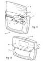
- Fig. 11is a bottom perspective view of an exemplary communication device 70 having a first and second communication module 72 and 74, in which the first communication module includes a protective movable door 76.
- the protective movable door 76is preferably fabricated from the same or similar material as the housing of the first communication module 72, and is positioned on a surface adjacent the cavity in which the second communication module 74 is mounted in its inoperative assembled position.
- the door 76is normally in a closed position protecting the second communication module 74 and connection terminals 78 (if present), and is movable to allow detachment of the second communication module 74 from the first communication module 72. Then, when the second communication module 74 is detached from the first communication module 72, the door 76 may be moved to its closed position to substantially cover the cavity 80 in the first communication module 72.
- the door 76may be attached to the first communication module 72 through any appropriate hinge arrangement, and is preferably biased toward its open and closed positions. For instance, if an over-center spring or elastic biasing hinge arrangement is utilized, the door 76 is preferably biased toward its open position when the door 76 is opened beyond some point in its range of motion, and is otherwise biased toward its closed position. In addition, the door 76 may also include a fastening means or locking mechanism for maintaining the door in its closed position. Other specific ranges of motion are also contemplated in accordance with this aspect of the invention, including but not limited to a downwardly or sideways swinging door or a similar sliding door or covering panel.
- the door 76may also serve a decorative purpose. If fabricated from the same material as the housing of the first module 72, which is typically opaque, the door may, for example, be molded or otherwise worked to bear an emblem, a logo, a user identifier or the like, as shown at 79 in Fig. 12 . Alternatively, the door 76 may be fabricated from a transparent material and adapted to receive a decorative member such as a photograph, allowing a user to customize the appearance of the communication device according to personal taste and preference.
- Fig. 13shows another exemplary communication device 80 in which a first communication module 82 includes a substantially enclosed cavity 86 into which a second communication module 84 is mounted.
- the second communication module 84is mounted by sliding it into the cavity 86 in a direction indicated by the dotted line 94.
- the first communication module 82 and second communication module 84preferably include suitable retaining means for removably holding the second communication module 84 within the cavity 86.
- the communication modules 82 and 84may be adapted for operation in accordance with any of the examples described above.
- an opening 92preferably comprising a series of slits as shown in Fig. 13 , may be provided at an appropriate position in a wall of the housing of first communication module 82.
- the slitsare positioned to correspond to the position of a microphone 84d when the second communication module 84 is in its operative assembled position.
- a further opening similar to opening 92could be provided for a speaker 84a.
- the operative assembled positioncould be designed such that the speaker 84a remains outside the cavity 86.
- a set of contact terminals 88 on the second communication module 84may cooperate with suitably located terminals inside cavity 86 to provide for recharging of a power source in the second module 84 and/or powering the second module 84 from the power source in the first module 82.
- a set of female terminals 90may be located at a bottom edge of the main body 84b of the second communication module 84 that engage and electrically connect to corresponding male terminals inside the cavity 86.
- FIGs. 14a and 14brespectively show exemplary embodiments 100 and 110 in which the first communication module is a cellular telephone 102 and a laptop computer or PDA 112.
- a second communication module 104is removably assembled in a cavity 106 in the cellular telephone 102.
- the laptop computer or PDA 112 shown in Fig. 14bincludes a mounting location 116 in which a second communication module 114 may be attached.
- Any of the above terminal and mounting arrangementsincluding, for example, a protective door or an enclosed cavity in which the second communication modules 104 or 114 would be slidably mounted, are also contemplated for the devices 100 and 110.
- Figs. 15a and 15bshow one alternative design 120 for the second communication module.
- Fig. 15ashows a top perspective view of the alternative second communication module 120.
- Fig. 15bshows a side perspective view of the alternative second communication module 120.
- the alternative communication module 120preferably includes a housing 128, a speaker 120a, a microphone 120d and a switch 126.
- the housing 121preferably includes a substantially oval-shaped top profile, and indentations 122 and 124 that define handles by which a user may grasp and hold the second communication module 120.
- the housing 121preferably has a main body portion with two sections: an upper section 120b that lies substantially to one side of the speaker 120a; and a lower section 120c that lies substantially on the opposite side of the speaker 120a.
- the microphone 120dis preferably located at a distal end of the lower section 120c.
- the switch 126is preferably located on a top portion of the housing 121 and operates similarly to the switch 54 shown in Fig. 5 .
- the modulemay also include an additional microphone adapted to receive background noise for use in executing noise cancellation operations for the desired but corrupted voice or audio signals received at microphone 120d.
- the alternative module 120communicates via a wireless link with an associated first communication module and is designed to provide for hands-free operation.
- the speaker 120ais placed in a user's ear such that body section 120c and thus microphone 120d extend toward the user's mouth. Extension of the upper and lower main body sections 120b and 120c on opposite sides of the speaker 120a allows for effective weight balancing.
- a further feature of the alternative second communication module 120involves a raised portion 128 that overlies the upper and lower main body sections 120b and 120c.
- the raised portion 128is preferably a removable cover member that provides simple access to manufacturer-selected internal components, such as a single-use replaceable battery, for service or installation by a user.
- FIG. 16is an exemplary electrical block diagram 160 of the multi-module communication devices shown in FIGs. 1-15 .
- Another type of communication device that could be modified for use with this systemis described in co-pending United States Patent Applications S/N 09/106,585 , 09/344,432 , 09/543,231 , 09/634,774 and 09/663,972 . These applications are co-owned with the present application.
- the communication devices described in these applicationsinclude only a single wireless RF component for communicating over a single communication path to a long-range wireless network.
- the devices shown in FIGs. 1-15are similar to these devices in that they can communicate over a long-range wireless network, but also preferably include an RF interface for communicating over a short-range wireless network or link.
- the communication devices 160 shown in FIGs. 1-15preferably comprise a first communication module 161 and a second communication module 162.
- the first communication module 161preferably includes a pair of antennas 164,166 (although a single antenna structure could be used), a processor 174, a memory 172, an LCD display 180, at least one rechargeable battery 184, a long-range RF transceiver 168, one or more short-range RF transceivers 170, a power supply and recharging circuit 186, a cradle interface circuit 182, and one or more input devices, including, preferably, a keyboard 176 such as described in the above mentioned co-pending applications and a thumbwheel 178.
- the first communication module 161may also include a pressure-sensitive writing tablet.
- the input devices 176,178 on the first communication module 161are preferably used to respond to and generate messages, such as email messages.
- the first communication module 161preferably interfaces with a belt-wom holster for receiving the first communication module 161 and securing it to a user's belt.
- the long-range RF transceiver 168is used to send and receive information from the long-range wireless network, and the one or more short-range RF transceivers 170 are used to send and receive information from the second communication module 162, and possibly from other local devices such as an RF interface cradle.
- the second communication module 162is preferably an RF-enabled ear-piece that may be connected to (both mechanically and electrically) the first communication module 161 as described above.
- the second communication module 162preferably includes a microphone and a speaker 190, a short-range wireless transceiver 192, an antenna 194, a rechargeable battery 188, and possibly an integral processor 196.
- the second communication module 162may also include a background noise microphone 48 and a noise cancellation circuit 191 as described above with reference to Fig. 4 .
- a shared secretcan be exchanged between the two wireless components of the communication device 160 so that any communications between the first and second communication modules 161/162 may be encrypted.
- the rechargeable battery 188 of the second module 162may be recharged by the battery 184 of the first communication module 161 through power supply recharging circuitry 186 when the two modules are in electrical contact.
- the communication device 160may include a camera component for displaying or sending video images to the communication device user, or could include sensory circuits for monitoring the communication device user's vital information such as pulse and blood pressure.
- a nurse or doctor in a hospital floorcould wear the first component, while the second might be in a patient's room monitoring some vital statistics.
- the short-range communication in this examplemight reach several hundred feet and several second components might be communicating to a single first component. This information could then be relayed on from the first component worn by the nurse or doctor to a central nursing station for all nurses on duty to see and monitor.
- Fig. 17illustrates one contemplated implementation 200 of the communication device described above, wherein 212 denotes the first communication module and 214 is the second communication module.
- the first communication module 212 and second communication module 214incorporate compatible short-range communication systems. This allows wireless communications between the first and second modules 212 and 214 over a short-range RF link 216.
- the first communication module 212is also designed for communication over a wireless link 218 with a long-range wireless communication network 220.
- the first communication module 21is preferably a mobile communication device such as a cellular telephone, a two-way pager or communications-enabled PDA, which would normally be carried by users in or on a belt clip or holder, or in a briefcase or purse.
- the second communication module 214is preferably a relatively low cost item, such that a user of a multiple-module device could purchase and suitably configure several second communication modules 214 for use with a single first communication module 212.
- the different second communication modules 214could preferably be purchased "off-the-shelf" and then configured, for example, through an over-the-air registration process executed under user control of the first communication module 212.
- the basic system 200could be expanded in accordance with a further example shown in Fig. 18 to include wireless communication between the device modules 212 and 214 and a third module 234, such as an RF interface cradle.
- the third module 234may be a docking station or cradle into or upon which the first module may be removably placed in order to recharge its power source.
- the second communication module 214is also powered by a rechargeable source, then the second module 214 may also be recharged by mounting the fully assembled multiple-module communication device on the third module 234.
- a more detailed illustration of the third module 234is shown in Fig. 18a .
- the third module 234is preferably adapted for short-range communications with either the first communication module 21 over the a short range RF link 236, the second communication module 214 over another short range RF link 238, or both.
- Many possible uses of such the additional short range RF links 236 and 238are possible.
- the third module 234may be connected to a desktop computer 232 as shown in Figs. 18 and 18a to expand the capabilities and potential applications of multiple module communication devices.
- the wireless links 236 and 238may then be used to carry data and audio signals between the user and the computer 232, as well as any wired network 234 and associated components to which the computer is connected.
- the third module 234could alternatively be integrated into the computer 232.
- Communication between the multiple-module device 212/214 and the computer 232provides for countless possible functionality options, such as simple paging and other notification, remote- and voice-activated computer and peripheral control and wireless file or information downloading and uploading.
- This systemmay also be further expanded to include network communications between the first and second communication modules 212 and 214 and wired network 234 through the PC 232 to incorporate connectivity via small pico-cell networks.
- each third module 234 connected to a corporate or other local area network such as the wired network 234,could be adapted to perform pico-cell base station functions.
- Each such "base station" third module 232could, for example, then be configured for short-range communication with the first and/or second communication modules 212 and 214 of all multiple-module communication devices issued to corporate employees.
- PANpersonal area network
- the second communication module 214may provide a hands-free means for a user to answer and participate in a voice call received at the cellular telephone. If the modules were adapted for voice control, a cellular user may preferably initiate a telephone call, add a telephone number to a stored number list, cause the telephone to enter a locked mode, or control execution of other functions by the first module by simply speaking into the microphone of the second communication module 214.
- the second communication module 214may expand its functionality. For instance, if the first communication module 212 is based on a data communication device, such as a two-way pager or a wireless modem in a laptop computer, then the addition of the second communication module 214 will enable voice communications in a device which was previously enabled only for data communication.
- a multiple-module communication device in accordance with this aspect of the inventioncan provide simultaneous voice and data communications. For example, a user that is participating in a voice communication using the second communication module 214 would preferably be able to simultaneously transmit data to the other parry to the call through the first communication module 212.
Landscapes
- Engineering & Computer Science (AREA)
- Signal Processing (AREA)
- Computer Networks & Wireless Communication (AREA)
- Multimedia (AREA)
- Telephone Set Structure (AREA)
- Transceivers (AREA)
Description
- This application claims priority from and is related to the following prior application: "Communication Device With Multiple Detachable Communication Modules", United States Provisional Application No.
60/246,533, filed November 7, 2000 - This invention relates to communication devices in general, and particularly to wireless communication devices having multiple detachably communication modules.
- There has been a proliferation of wireless mobile communication devices in recent years in the field of telecommunications. Devices such as cordless and cellular telephones, pagers, wireless modems, wireless email devices, personal digital assistants (PDAs) with communications functions, and other mobile communication devices are becoming commonplace. Known communication devices, however, are typically single-element or single-module designs. In order to enable hands-free operation of such single-module communication devices, specialized additional equipment is typically required. For example, a wired headset is often available for known communication devices that typically connects to the communication device through an electrical jack or plug. Another common hands-free accessory available for cellular telephones is a docking cradle, which is typically intending for mounting the communication device in a vehicle.
US-A-5,943,627 discloses a mobile cellular phone including: a radio handset and a mobile cellular phone body for transmitting and receiving a sound and a signal information through a wireless channel; and a holder disposed in the body for accommodating the radio handset to that when the radio handset is detached from the holder the body can relay the sound and the signal information between the radio handset and a base station to thereby enable a telecommunication to be realized through the radio handset and when the radio handset is accommodated in the holder, the telecommunication can be realized through the body.- According to one aspect of this invention, there is provided a communication device as defined in
claim 1 of the appended claims. - Features of embodiments are defined in the dependent claims.
Fig. 1 is a bottom perspective view of an exemplary communication device having a first communication module and a second detachable communication module for insertion into the communication device user's ear;Fig. 2 is another bottom perspective view of the exemplary communication device shown inFig. 1 , in which the second communication module has been removed from the first communication module;Fig. 3 provides a more detailed view of the cavity in the housing of the first communication module;Fig. 4 is a top perspective view of the second communication module shown inFigs. 1 and 2 ;Fig 5 is a bottom perspective view of the second communication module that shows additional exemplary features, including a power switch and charging terminals;Fig. 6 is a bottom perspective view of the communication device showing operative-mode connection terminals on the second communication module;Fig. 7 is a bottom perspective view of the first communication module showing both operative-mode connection terminals and inoperative-mode connection terminals;Fig. 8 is a bottom perspective view of the second communication module showing inoperative-mode connection terminals;Fig. 9 is a bottom perspective view of the first communication module showing the multifunctional connection terminals;Fig. 10 is a bottom perspective view of the second communication module showing a set of charging terminals;Fig. 11 is a bottom perspective view of an exemplary communication device having a first and second communication module, in which the first communication module includes a protective movable door;Fig. 12 shows a movable door that is molded or otherwise worked to bear an emblem, a logo, a user identifier or the like;Fig. 13 shows another exemplary communication device in which a first communication module includes a substantially enclosed cavity into which a second communication module is mounted;Figs. 14a and 14b respectively show examples in which the first communication module is a cellular telephone and a laptop computer or PDA;Fig. 15a shows a top perspective view of an alternative second communication module;Fig. 15b shows a side perspective view of the alternative second communication module;FIG. 16 is an exemplary electrical block diagram of the multi-module communication devices shown inFIGs. 1-15 ;Fig. 17 illustrates one contemplated implementation of the communication device described above;Fig. 18 illustrates a further example of a communication device that includes wireless communication between the device modules and a third module, such as an RF interface cradle; andFig. 18a is a more detailed illustration of the third module shown inFig. 18 .- Referring now to the drawing figures,
Fig. 1 is a bottom perspective view of anexemplary communication device 10 having afirst communication module 12 and a seconddetachable communication module 14 for insertion into the communication device user's ear. Thefirst communication module 12 includes a housing with substantially parallel and planar opposite top andbottom walls opposite side walls 4a and 4b, and substantially parallel and planar opposite front andback walls 6a and 6b. Theback wall 6b preferably includes bevelled surfaces 8a-8d located along the edges where theback wall 6b adjoins the top, bottom andside walls side walls top wall 2a,bottom wall 2b andside walls 4a and 4b are preferably slightly curved, but may also be planar. The specific shapes of the housing walls are dependent upon the requirements of thefirst communication module 12, as will become apparent from the following description. Fig. 2 is another bottom perspective view of theexemplary communication device 10 shown inFig. 1 , in which thesecond communication module 14 has been removed from thefirst communication module 12. The housing of thefirst communication module 12 preferably includes acavity 16 in which the second communication module may be detachably mounted.Fig. 3 provides a more detailed view of thecavity 16 in the housing of thefirst communication module 12. Thecavity 16 preferably includes a plurality of subcavities that are shaped to accommodate thesecond communication module 12, each of which may be a different size, shape and depth. For instance, the exemplary cavity shown inFig. 3 includes three subcavities: a substantiallycircular subcavity 18 having a first depth, a firstrectangular cavity 20 having a second depth, and a secondrectangular cavity 22 having a third depth. Thecavity 16 also preferably includes a plurality ofsurfaces subcavities surfaces second communication module 14 is mounted as inFig. 1 .- The surfaces of the
cavity 16 preferably also provide for retention of thesecond communication module 14 within thecavity 16.Surfaces surfaces second communication module 14 in order to frictionally hold it within thecavity 16. In another example, surfaces in or adjacent to thecavity 16 may include retention means, such as nubs or protrusions, that engage detents in corresponding parts of thesecond communication module 14, or vice versa, to detachably hold thesecond communication module 14 within thecavity 16. In yet another example, other retention means, such as springs or otherwise elastically-biased protrusions or hooks, may be included on the first or second communication module that cooperate with appropriate mating retention means on the other of the first or second communication module. Alternatively, additional means to maintain the device in an assembled position, such as a movable clip arrangement, could be mounted on thefirst communication module 12. - In order to remove the
second communication module 14 from thecavity 16, thesurfaces spaces Fig. 1 ) that enable a communication device user to grasp the sides of thesecond communication module 14. In addition, thesecond communication module 14 preferably includesdepressions 50 and 52 (shown inFigs. 4 and 5 ) that enable the communication device user to easily grip themodule 14 while it is within thecavity 16. Preferably, the retention means described above are adapted to apply sufficient force to retain thesecond communication module 14 in a mounted position, while allowing a communication device user to easily remove thesecond communication module 14 for use. Fig. 4 is a top perspective view of thesecond communication module 14 shown inFigs. 1 and 2 . Thesecond communication module 14 is preferably a voice communication device that includes aspeaker 14a, amain body 14b, aboom 14c and amicrophone 14d. Operationally, thespeaker 14a is placed in the ear of a communication device user with theboom 14c extending towards the user's mouth. To avoid rotational movement of thesecond communication module 14 while thespeaker 14a is in the user's ear, the center of gravity of themodule 14 should preferably be as close to thespeaker 14a as possible. Thus, any relatively heavy components located inside themain body portion 14b should preferably be located adjacent thespeaker 14a. In this manner, moments about the speaker are minimized, and thesecond communication module 14 should remain substantially stationary while the speaker is in the communication device user's ear.- Optimally, the length of the
boom portion 14c should be maximized such that themicrophone 14d is located in the proximity of the communication device user's mouth when themodule 14 is in use. The moment about thespeaker 14a, however, increases in proportion to the length of theboom 14c. Thus, in order to maintain stability, the length of theboom 14c may not be sufficient to position themicrophone 14d adjacent to a user's mouth. Themicrophone 14d will, therefore, likely receive not only a user's speech, but also undesired noise signals from a multitude of sources, such as other speakers in the vicinity or car engine noise. In order to reduce this background noise, the second communication module preferably includes a noise cancellation circuit with abackground noise microphone 48 as shown inFig. 4 . Thebackground noise microphone 48 preferably detects background noise signals which are then subtracted from the corrupted speech received by themicrophone 14d in the noise cancellation circuit. In this manner, a higher quality speech signal is provided. Fig 5 is a bottom perspective view of thesecond communication module 14 that shows additional exemplary features, including apower switch 54 and chargingterminals 56. Thepower switch 54 is preferably a pushbutton switch that turns thesecond communication module 14 on and off, enabling the communication device user to limit power consumption while themodule 14 is not in use. In an example, thesecond communication module 14 is also configured to turn on automatically when removed from its assembled position within thefirst communication module 12, and to turn off automatically when replaced in its mounted position. In this example, thepower switch 54 may be used to turn off the second communication module 13 without returning it to its mounted position. In other examples, thesecond communication module 14 may also include other switched functions, such as a mute function, controlled by one or more additional switches located on the first and/or second module. For example, a mute function may operate to disable themicrophone 14d and thebackground noise microphone 48 without ending a communication function such as a voice call.- The charging
terminals 56 on thesecond communication module 14 preferably mate withcorresponding charging terminals 46 on thefirst communication module 12 shown inFig. 3 . Also shown inFigs. 3 and5 arealternative locations 46a and 56a for the respective charging terminals. Thesecond communication module 14 preferably includes a rechargeable power source that is recharged by thefirst communication module 12 through the chargingterminals Fig. 1 . The chargingterminals 46 on thefirst communication module 12 are preferably coupled to an internal power source through appropriate conversion and control circuitry in order to provide a charge to an additional power source in the second communication module. - In addition, the charging
terminals terminals 56 may be recessed below the surface of themain body 14b of thesecond communication module 14 in order to reduce the likelihood of external contact with the chargingterminals 56, resulting in a short-circuit. In such an example, the chargingterminals 46 on thefirst communication module 12 may protrude from thesurface 26b in order to make contact with recessedcharging terminals 56 in thesecond communication module 14. - With reference to
Fig. 3 , thefirst communication module 12 may include either a non-rechargeable power source such as one or more alkaline batteries, or a rechargeable source. In devices where thefirst communication module 12 includes a rechargeable power supply, the power supply is preferably recharged through an operative connection to a recharging device, such as a cradle or holding unit. Thedevice 10 could also be adapted to receive a connector jack or plug from a more common wall-mounted type charger device. - With reference again to
Fig. 5 , thesecond communication module 14 preferably includes a rechargeable power source that is charged through therecharging terminals second communication module 14 may alternatively include a single use power source, such as a non-rechargeable battery, making chargingterminals Figs. 6-8 show analternative communication device 60 embodiment in which asecond communication module 64 may be mounted to afirst communication module 62 in either an operative or inoperative position.Fig. 6 is a bottom perspective view of thecommunication device 60 showing operative-mode connection terminals 66 on thesecond communication module 64.Fig. 7 is a bottom perspective view of thefirst communication module 62 showing both operative-mode connection terminals 68 and inoperative-mode connection terminals 46.Fig. 8 is a bottom perspective view of thesecond communication module 64 showing inoperative-mode connection terminals 56.- When the
second communication module 64 is mounted in an inoperative assembled position, the inoperative-mode terminals 46 in thefirst communication module 62 are electrically connected with the inoperative-mode terminals 56 on afront wall 64b of thesecond communication module 64, as shown inFig. 8 . In the inoperative assembled position, the inoperative-mode terminals second communication module 64. - When the
second communication module 64 is mounted in an operative assembled position, the operative-mode connection terminals 68 in the cavity of thefirst communication module 62, shown inFig. 7 , are electrically connected with the operative-mode connection terminals 66 on a back wall of a main body portion of thesecond communication module 64 shown inFig. 6 . In this operative assembled position, thespeaker 64a andmicrophone 64d, shown inFig. 8 face away from the cavity and are accessible for use by a user of the communication device. In addition, the operative-mode terminals second communication module 64. For instance, the operative-mode terminals second communication module 64 from the power source of thefirst communication module 62, while simultaneously charging the power source of thesecond communication module 64. The operative assembled position of thesecond communication module 64 thus provides for use of thesecond communication module 64 when its power source is incapable of supplying sufficient power, and thereby avoids recharge down time. - Any of the retaining means discussed above could be used to mount the
second module 64 in the operative position. For example, a friction fit between themain body 64b of thesecond communication module 64 and the corresponding cavity in thefirst communication module 62 will preferably retain thesecond module 64 in its assembled inoperative position. Themain body 64b, or at least a part thereof, could then be fabricated such that the back portion, in whichterminals 66 are positioned, and the front portion are substantially symmetric. Thesecond communication module 64 may then be retained in either its operative or inoperative assembled position within the cavity in thefirst communication module 62. A similar arrangement could alternatively be implemented based on friction fit retention of theboom portion 64c of thesecond communication module 64. Figs. 9 and 10 show another example 61 of a communication device in which asecond communication module 65 may be mounted to afirst communication module 63 in either an operative or inoperative position, and thefirst communication module 63 utilizes only one set ofmultifunctional connection terminals 67.Fig. 9 is a bottom perspective view of thefirst communication module 63 showing themultifunctional connection terminals 67.Fig. 10 is a bottom perspective view of the second communication module showing a set of chargingterminals 69. One function of theconnection terminals 67 on thefirst communication module 63 may be to cooperate with the chargingterminals 69 positioned on thesecond communication module 65 in order to supply power to a rechargeable power source in thesecond communication module 65 while it is mounted in the inoperative position. In addition, themultifunctional connection terminals 67 may also contact a second set of terminals on the top face of the second communication module 65 (as shown inFig. 6 ) when thesecond communication module 65 is mounted in its operative assembled position. Themultifunctional connection terminals 67 may then provide for simultaneous charging and use of thesecond communication module 65 while it is mounted in its operative position.Fig. 11 is a bottom perspective view of anexemplary communication device 70 having a first andsecond communication module movable door 76. The protectivemovable door 76 is preferably fabricated from the same or similar material as the housing of thefirst communication module 72, and is positioned on a surface adjacent the cavity in which thesecond communication module 74 is mounted in its inoperative assembled position. Thedoor 76 is normally in a closed position protecting thesecond communication module 74 and connection terminals 78 (if present), and is movable to allow detachment of thesecond communication module 74 from thefirst communication module 72. Then, when thesecond communication module 74 is detached from thefirst communication module 72, thedoor 76 may be moved to its closed position to substantially cover thecavity 80 in thefirst communication module 72.- The
door 76 may be attached to thefirst communication module 72 through any appropriate hinge arrangement, and is preferably biased toward its open and closed positions. For instance, if an over-center spring or elastic biasing hinge arrangement is utilized, thedoor 76 is preferably biased toward its open position when thedoor 76 is opened beyond some point in its range of motion, and is otherwise biased toward its closed position. In addition, thedoor 76 may also include a fastening means or locking mechanism for maintaining the door in its closed position. Other specific ranges of motion are also contemplated in accordance with this aspect of the invention, including but not limited to a downwardly or sideways swinging door or a similar sliding door or covering panel. - Although intended primarily for protecting the
second module 74 when it is mounted on thefirst module 72, thedoor 76 may also serve a decorative purpose. If fabricated from the same material as the housing of thefirst module 72, which is typically opaque, the door may, for example, be molded or otherwise worked to bear an emblem, a logo, a user identifier or the like, as shown at 79 inFig. 12 . Alternatively, thedoor 76 may be fabricated from a transparent material and adapted to receive a decorative member such as a photograph, allowing a user to customize the appearance of the communication device according to personal taste and preference. Fig. 13 shows anotherexemplary communication device 80 in which afirst communication module 82 includes a substantially enclosedcavity 86 into which asecond communication module 84 is mounted. Preferably, thesecond communication module 84 is mounted by sliding it into thecavity 86 in a direction indicated by the dottedline 94. Thefirst communication module 82 andsecond communication module 84 preferably include suitable retaining means for removably holding thesecond communication module 84 within thecavity 86.- The
communication modules device 80 provides for an operative assembled position of the second communication module 13, then anopening 92, preferably comprising a series of slits as shown inFig. 13 , may be provided at an appropriate position in a wall of the housing offirst communication module 82. Preferably, the slits are positioned to correspond to the position of amicrophone 84d when thesecond communication module 84 is in its operative assembled position. Depending on the particular operative assembled position of thesecond communication module 84, a further opening similar to opening 92 could be provided for a speaker 84a. Alternatively, the operative assembled position could be designed such that the speaker 84a remains outside thecavity 86. - In addition, a set of
contact terminals 88 on thesecond communication module 84 may cooperate with suitably located terminals insidecavity 86 to provide for recharging of a power source in thesecond module 84 and/or powering thesecond module 84 from the power source in thefirst module 82. In an alternative example, a set offemale terminals 90 may be located at a bottom edge of themain body 84b of thesecond communication module 84 that engage and electrically connect to corresponding male terminals inside thecavity 86. - Each of the above examples include a general first communication module. This first communication module may, for example be a handheld electronic device as disclosed in United States Patent Application No.
09/106,585 Figs. 14a and 14b respectively showexemplary embodiments cellular telephone 102 and a laptop computer orPDA 112. InFig. 14a , asecond communication module 104 is removably assembled in acavity 106 in thecellular telephone 102. Similarly, the laptop computer orPDA 112 shown inFig. 14b includes a mountinglocation 116 in which asecond communication module 114 may be attached. Any of the above terminal and mounting arrangements, including, for example, a protective door or an enclosed cavity in which thesecond communication modules devices Figs. 15a and 15b show onealternative design 120 for the second communication module.Fig. 15a shows a top perspective view of the alternativesecond communication module 120.Fig. 15b shows a side perspective view of the alternativesecond communication module 120. Thealternative communication module 120 preferably includes ahousing 128, aspeaker 120a, amicrophone 120d and aswitch 126. Thehousing 121 preferably includes a substantially oval-shaped top profile, andindentations second communication module 120. In addition, thehousing 121 preferably has a main body portion with two sections: anupper section 120b that lies substantially to one side of thespeaker 120a; and alower section 120c that lies substantially on the opposite side of thespeaker 120a. Themicrophone 120d is preferably located at a distal end of thelower section 120c. Theswitch 126 is preferably located on a top portion of thehousing 121 and operates similarly to theswitch 54 shown inFig. 5 . The module may also include an additional microphone adapted to receive background noise for use in executing noise cancellation operations for the desired but corrupted voice or audio signals received atmicrophone 120d.- Like the second communication modules described above, the
alternative module 120 communicates via a wireless link with an associated first communication module and is designed to provide for hands-free operation. Thespeaker 120a is placed in a user's ear such thatbody section 120c and thusmicrophone 120d extend toward the user's mouth. Extension of the upper and lowermain body sections speaker 120a allows for effective weight balancing. A further feature of the alternativesecond communication module 120 involves a raisedportion 128 that overlies the upper and lowermain body sections portion 128 is preferably a removable cover member that provides simple access to manufacturer-selected internal components, such as a single-use replaceable battery, for service or installation by a user. FIG. 16 is an exemplary electrical block diagram 160 of the multi-module communication devices shown inFIGs. 1-15 . Another type of communication device that could be modified for use with this system is described in co-pending United States Patent ApplicationsS/N 09/106,585 09/344,432 09/543,231 09/634,774 09/663,972 FIGs. 1-15 are similar to these devices in that they can communicate over a long-range wireless network, but also preferably include an RF interface for communicating over a short-range wireless network or link.- The
communication devices 160 shown inFIGs. 1-15 preferably comprise afirst communication module 161 and asecond communication module 162. Thefirst communication module 161 preferably includes a pair of antennas 164,166 (although a single antenna structure could be used), aprocessor 174, amemory 172, anLCD display 180, at least onerechargeable battery 184, a long-range RF transceiver 168, one or more short-range RF transceivers 170, a power supply and rechargingcircuit 186, acradle interface circuit 182, and one or more input devices, including, preferably, akeyboard 176 such as described in the above mentioned co-pending applications and athumbwheel 178. Thefirst communication module 161 may also include a pressure-sensitive writing tablet. - The input devices 176,178 on the
first communication module 161 are preferably used to respond to and generate messages, such as email messages. Thefirst communication module 161 preferably interfaces with a belt-wom holster for receiving thefirst communication module 161 and securing it to a user's belt. The long-range RF transceiver 168 is used to send and receive information from the long-range wireless network, and the one or more short-range RF transceivers 170 are used to send and receive information from thesecond communication module 162, and possibly from other local devices such as an RF interface cradle. - The
second communication module 162 is preferably an RF-enabled ear-piece that may be connected to (both mechanically and electrically) thefirst communication module 161 as described above. Thesecond communication module 162 preferably includes a microphone and aspeaker 190, a short-range wireless transceiver 192, anantenna 194, arechargeable battery 188, and possibly anintegral processor 196. Thesecond communication module 162 may also include abackground noise microphone 48 and anoise cancellation circuit 191 as described above with reference toFig. 4 . When thesecond communication module 162 is placed into thefirst communication module 161, a shared secret can be exchanged between the two wireless components of thecommunication device 160 so that any communications between the first andsecond communication modules 161/162 may be encrypted. Also, therechargeable battery 188 of thesecond module 162 may be recharged by thebattery 184 of thefirst communication module 161 through powersupply recharging circuitry 186 when the two modules are in electrical contact. - In other examples, the
communication device 160 may include a camera component for displaying or sending video images to the communication device user, or could include sensory circuits for monitoring the communication device user's vital information such as pulse and blood pressure. In these examples a nurse or doctor in a hospital floor could wear the first component, while the second might be in a patient's room monitoring some vital statistics. The short-range communication in this example might reach several hundred feet and several second components might be communicating to a single first component. This information could then be relayed on from the first component worn by the nurse or doctor to a central nursing station for all nurses on duty to see and monitor. Fig. 17 illustrates one contemplatedimplementation 200 of the communication device described above, wherein 212 denotes the first communication module and 214 is the second communication module. In thissystem 200, thefirst communication module 212 andsecond communication module 214 incorporate compatible short-range communication systems. This allows wireless communications between the first andsecond modules range RF link 216. Thefirst communication module 212 is also designed for communication over awireless link 218 with a long-rangewireless communication network 220. In thisimplementation 200, the first communication module 21 is preferably a mobile communication device such as a cellular telephone, a two-way pager or communications-enabled PDA, which would normally be carried by users in or on a belt clip or holder, or in a briefcase or purse.- The
second communication module 214 is preferably a relatively low cost item, such that a user of a multiple-module device could purchase and suitably configure severalsecond communication modules 214 for use with a singlefirst communication module 212. The differentsecond communication modules 214 could preferably be purchased "off-the-shelf" and then configured, for example, through an over-the-air registration process executed under user control of thefirst communication module 212. - The
basic system 200 could be expanded in accordance with a further example shown inFig. 18 to include wireless communication between thedevice modules third module 234, such as an RF interface cradle. If thefirst communication module 212 includes a rechargeable power source, then thethird module 234 may be a docking station or cradle into or upon which the first module may be removably placed in order to recharge its power source. If thesecond communication module 214 is also powered by a rechargeable source, then thesecond module 214 may also be recharged by mounting the fully assembled multiple-module communication device on thethird module 234. A more detailed illustration of thethird module 234 is shown inFig. 18a . - The
third module 234 is preferably adapted for short-range communications with either the first communication module 21 over the a shortrange RF link 236, thesecond communication module 214 over another shortrange RF link 238, or both. Many possible uses of such the additional shortrange RF links third module 234 may be connected to adesktop computer 232 as shown inFigs. 18 and 18a to expand the capabilities and potential applications of multiple module communication devices. The wireless links 236 and 238 may then be used to carry data and audio signals between the user and thecomputer 232, as well as anywired network 234 and associated components to which the computer is connected. Although shown as separate components inFigs. 18 and 18a , thethird module 234 could alternatively be integrated into thecomputer 232. - Communication between the multiple-
module device 212/214 and thecomputer 232 provides for countless possible functionality options, such as simple paging and other notification, remote- and voice-activated computer and peripheral control and wireless file or information downloading and uploading. This system may also be further expanded to include network communications between the first andsecond communication modules wired network 234 through thePC 232 to incorporate connectivity via small pico-cell networks. In such an implementation, eachthird module 234 connected to a corporate or other local area network such as thewired network 234, could be adapted to perform pico-cell base station functions. Each such "base station"third module 232 could, for example, then be configured for short-range communication with the first and/orsecond communication modules range wireless network 220, potentially generating significant cost savings. A further extension of the communication systems according to the above examples could be a personal area network (PAN). - Many different possibilities for inter-module communications features are also possible. For instance, if the
first communication module 212 is a cellular telephone, then thesecond communication module 214 may provide a hands-free means for a user to answer and participate in a voice call received at the cellular telephone. If the modules were adapted for voice control, a cellular user may preferably initiate a telephone call, add a telephone number to a stored number list, cause the telephone to enter a locked mode, or control execution of other functions by the first module by simply speaking into the microphone of thesecond communication module 214. - If the
first communication module 212 is enabled for data communication, then thesecond communication module 214 may expand its functionality. For instance, if thefirst communication module 212 is based on a data communication device, such as a two-way pager or a wireless modem in a laptop computer, then the addition of thesecond communication module 214 will enable voice communications in a device which was previously enabled only for data communication. A multiple-module communication device in accordance with this aspect of the invention can provide simultaneous voice and data communications. For example, a user that is participating in a voice communication using thesecond communication module 214 would preferably be able to simultaneously transmit data to the other parry to the call through thefirst communication module 212. - The examples described herein are examples of structures, systems or methods having elements corresponding to the elements of the invention recited in the claims. This written description may enable those skilled in the art to make and use embodiments having alternative elements that likewise correspond to the elements of the invention recited in the claims. The intended scope of the invention thus includes other structures, systems or methods that do not differ from the literal language of the claims, and further includes other structures, systems or methods with insubstantial differences from the literal language of the claims.
Claims (8)
- A communication device(60), comprising:a first communication module (62) comprising a housing with a cavity defined therein and a set of charging terminals (46) located within the cavity, wherein the charging terminals are coupled to a power source; anda second communication module (64) comprising an outer housing (64b), a speaker (64a) attached to the outer housing and physically dimensioned to be fitted into an ear of a communication device user, a microphone (64d) attached to the outer housing and positioned to extend substantially towards the communication device user's mouth when the speaker is fitted into the ear of the communication device user, a rechargeable power source, and a set of terminals (56) attached to a bottom surface of the outer housing and coupled to the rechargeable power source, wherein the second communication module is physically dimensioned to be detachably mounted within the cavity of the first communication module such that the terminals on the second communication module are physically and mechanically coupled to the charging terminals while the second communication module is mounted within the cavity in order to charge the rechargeable power source,characterized in thatthe second communication module further comprises a set of operational terminals (66) attached to a top surface of the outer housing and coupled to the rechargeable power source,wherein the second communication module is adapted to be mounted in the cavity of the first communication module in either an inoperative position in which the charging terminals (46) in the cavity are coupled to the terminals (56) attached to the bottom surface of the outer housing,or an operative position in which a second set of charging terminals (68) in the cavity are coupled to the operational terminals (66) attached to the top surface or the outer housing.
- The communication device of claim 1, wherein the terminals (56) attached to the bottom of the outer housing (64b) of the second communication module (64) are recessed below a surface of the outer housing of the second communication module.
- The communication device of claim 2, wherein the charging terminals (46) located within the cavity of the first communication module (62) protrude from a surface of the cavity in order to physically contact the recessed (56) terminals in the second communication module.
- The communication device of claim 1, wherein the power source coupled to the charging terminals (68, 46) in the first communication module (62) is a power supply circuit coupled to a rechargeable power source.
- The communication device of claim 1, wherein the power source coupled to the charging terminals (68, 46) in the first communication module (62) is a power supply circuit coupled to a non-rechargeable power source.
- The communication device of claim 1, wherein the second set of charging terminals (68) of the first communication module (62) are coupled to the operational terminals (66) of the second communication module (64) while the second communication module is mounted in the operative position.
- The communication device of claim 1, wherein the power source in the first communication module (62) is a rechargeable power source, and wherein the first communication module is configured to be electrically and mechanically coupled to a third module in order to charge the rechargeable power source.
- The communication device of claim 1, wherein the cavity in the first communication module (62) is substantially enclosed such that the second communication module (64) is detachably mounted within the cavity by sliding the second communication module lengthwise into the cavity.
Applications Claiming Priority (3)
| Application Number | Priority Date | Filing Date | Title |
|---|---|---|---|
| US24653300P | 2000-11-07 | 2000-11-07 | |
| US246533P | 2000-11-07 | ||
| PCT/CA2001/001582WO2002039600A2 (en) | 2000-11-07 | 2001-11-06 | Communication device with multiple detachable communication modules |
Publications (2)
| Publication Number | Publication Date |
|---|---|
| EP1346483A2 EP1346483A2 (en) | 2003-09-24 |
| EP1346483B1true EP1346483B1 (en) | 2013-08-14 |
Family
ID=22931089
Family Applications (1)
| Application Number | Title | Priority Date | Filing Date |
|---|---|---|---|
| EP01993981.8AExpired - LifetimeEP1346483B1 (en) | 2000-11-07 | 2001-11-06 | Communication device with multiple detachable communication modules |
Country Status (5)
| Country | Link |
|---|---|
| US (4) | US7313423B2 (en) |
| EP (1) | EP1346483B1 (en) |
| AU (1) | AU2002218080A1 (en) |
| CA (1) | CA2432540C (en) |
| WO (1) | WO2002039600A2 (en) |
Cited By (4)
| Publication number | Priority date | Publication date | Assignee | Title |
|---|---|---|---|---|
| EP3153056A1 (en)* | 2015-09-30 | 2017-04-12 | Apple Inc. | Case with magnetic over-center mechanism |
| EP3196551A1 (en)* | 2007-01-06 | 2017-07-26 | Apple Inc. | Wireless headset comprising a housing and an earbud electrically coupled to the housing by a flexible circuit board |
| US20180255389A1 (en) | 2007-01-06 | 2018-09-06 | Apple Inc. | Headset connector |
| US11172101B1 (en) | 2018-09-20 | 2021-11-09 | Apple Inc. | Multifunction accessory case |
Families Citing this family (211)
| Publication number | Priority date | Publication date | Assignee | Title |
|---|---|---|---|---|
| US7339605B2 (en)* | 2004-04-16 | 2008-03-04 | Polycom, Inc. | Conference link between a speakerphone and a video conference unit |
| US7110789B1 (en)* | 2001-03-07 | 2006-09-19 | Kyocera Wireless Corp. | Wireless communications device docking system and method |
| US6978163B2 (en)* | 2002-03-11 | 2005-12-20 | Jabra Corporation | Multi-purpose dongle for wireless headset |
| US6850788B2 (en) | 2002-03-25 | 2005-02-01 | Masimo Corporation | Physiological measurement communications adapter |
| FR2844125B1 (en)* | 2002-09-03 | 2004-12-17 | Inventel Systemes | CENTRAL BASE FOR LOCAL PRIVATE RADIOCOMMUNICATION NETWORK AND RADIOCOMMUNICATION DEVICE INCLUDING SUCH A BASE. |
| US7512247B1 (en)* | 2002-10-02 | 2009-03-31 | Gilad Odinak | Wearable wireless ear plug for providing a downloadable programmable personal alarm and method of construction |
| JP4403076B2 (en) | 2002-10-22 | 2010-01-20 | ソニー エリクソン モバイル コミュニケーションズ, エービー | Split battery supply |
| ATE335352T1 (en)* | 2002-10-22 | 2006-08-15 | Sony Ericsson Mobile Comm Ab | BATTERY SUPPLY FOR A HEADPHONE SYSTEM |
| DE60326775D1 (en) | 2003-05-28 | 2009-04-30 | Nokia Corp | METHOD AND RADIO DEVICE ARRANGEMENT FOR DISPLAYING AN INCOMING CONNECTION |
| DE10331412A1 (en)* | 2003-07-10 | 2005-01-27 | Bayerische Motoren Werke Ag | Holder for a mobile phone |
| US20050059344A1 (en)* | 2003-09-12 | 2005-03-17 | Chia-Hao Chang | Accommodation device for bluetooth earphone |
| US7937117B2 (en)* | 2003-11-17 | 2011-05-03 | Gn Netcom A/S | Portable speakerphone with pivoting microphone boom |
| US7720445B2 (en)* | 2003-11-19 | 2010-05-18 | Symbol Technologies, Inc. | Modular access point |
| US20050136848A1 (en)* | 2003-12-22 | 2005-06-23 | Matt Murray | Multi-mode audio processors and methods of operating the same |
| US20050186905A1 (en)* | 2004-02-24 | 2005-08-25 | Tracy James L. | Independently actuating electronic components and method of operating therefor |
| US8331860B2 (en)* | 2004-06-29 | 2012-12-11 | Nokia Corporation | Control of peripheral devices in a short-range wireless communication system |
| US7899492B2 (en) | 2004-07-16 | 2011-03-01 | Sellerbid, Inc. | Methods, systems and apparatus for displaying the multimedia information from wireless communication networks |
| US20140071818A1 (en) | 2004-07-16 | 2014-03-13 | Virginia Innovation Sciences, Inc. | Method and system for efficient communication |
| US7957733B2 (en) | 2004-07-16 | 2011-06-07 | Sellerbid, Inc. | Method and apparatus for multimedia communications with different user terminals |
| JP4576920B2 (en)* | 2004-08-02 | 2010-11-10 | パナソニック株式会社 | Cordless earphone and mobile phone device with cordless earphone |
| KR100703408B1 (en)* | 2004-12-06 | 2007-04-03 | 삼성전자주식회사 | Horizontal Mounting Vertical Mounting Type Charging Cradle |
| US8489151B2 (en)* | 2005-01-24 | 2013-07-16 | Broadcom Corporation | Integrated and detachable wireless headset element for cellular/mobile/portable phones and audio playback devices |
| US20060245585A1 (en)* | 2005-04-29 | 2006-11-02 | Memphis-Zhihong Yin | Portable computer device with wireless earpiece |
| USD565003S1 (en)* | 2005-09-24 | 2008-03-25 | Samsung Electronics Co., Ltd. | Mobile phone |
| US20100130198A1 (en)* | 2005-09-29 | 2010-05-27 | Plantronics, Inc. | Remote processing of multiple acoustic signals |
| FI20055590A7 (en)* | 2005-11-03 | 2007-05-04 | Wearfone Oy | Method and device for wirelessly generating sound to a user's ear |
| US20070135185A1 (en)* | 2005-11-22 | 2007-06-14 | Motorola, Inc. | Modular multifunction speaker and headset |
| FR2895860A1 (en)* | 2006-01-05 | 2007-07-06 | Parrot Sa | Holder for receiving e.g. mobile telephone`s autonomous Bluetooth type wireless earpiece, has plate axially movable in direction of introduction of earpiece in receptacle, between inserted and released positions |
| GB2435986A (en)* | 2006-03-07 | 2007-09-12 | Andrew James Marcelin | A mobile telephone having a docking unit for a wireless headset |
| US8068882B2 (en)* | 2006-04-27 | 2011-11-29 | Plantronics, Inc. | Portable media player emulator for facilitating wireless use of an accessory |
| US9161696B2 (en) | 2006-09-22 | 2015-10-20 | Masimo Corporation | Modular patient monitor |
| US8840549B2 (en) | 2006-09-22 | 2014-09-23 | Masimo Corporation | Modular patient monitor |
| US7797041B2 (en)* | 2006-10-11 | 2010-09-14 | Cardiac Pacemakers, Inc. | Transcutaneous neurostimulator for modulating cardiovascular function |
| US7797046B2 (en)* | 2006-10-11 | 2010-09-14 | Cardiac Pacemakers, Inc. | Percutaneous neurostimulator for modulating cardiovascular function |
| TWM328731U (en)* | 2006-10-31 | 2008-03-11 | Quanta Comp Inc | Portable electronic device |
| US8650925B2 (en) | 2007-01-05 | 2014-02-18 | Apple Inc. | Extrusion method for fabricating a compact tube with internal features |
| US8391921B2 (en) | 2007-02-13 | 2013-03-05 | Google Inc. | Modular wireless communicator |
| US10027789B2 (en) | 2007-02-13 | 2018-07-17 | Google Llc | Modular wireless communicator |
| US7970433B2 (en) | 2007-06-08 | 2011-06-28 | Modu Ltd. | SD switch box in a cellular handset |
| CN101035149B (en)* | 2007-04-04 | 2012-07-04 | 王承延 | Radio earphone phone and calling method |
| US8369846B2 (en)* | 2007-04-19 | 2013-02-05 | Apple Inc. | Personal area network systems and devices and methods for use thereof |
| EP2137894B1 (en)* | 2007-04-19 | 2019-05-22 | Apple Inc. | Personal area network systems and devices and methods for use thereof |
| US8331987B2 (en)* | 2007-04-19 | 2012-12-11 | Apple Inc. | Personal area network systems and devices and methods for use thereof |
| US8364139B2 (en) | 2007-04-19 | 2013-01-29 | Apple Inc. | Personal area network systems and devices and methods for use thereof |
| US20100164432A1 (en)* | 2007-06-01 | 2010-07-01 | Plantronics, Inc. | Method and device for recharging a headset |
| CN101350843B (en)* | 2007-07-19 | 2011-12-07 | 信和昌科技股份有限公司 | Combination device for local communication |
| JP4889598B2 (en)* | 2007-08-31 | 2012-03-07 | 三洋電機株式会社 | Microphone holder and microphone device using the same |
| US7863862B2 (en)* | 2007-10-12 | 2011-01-04 | Research In Motion Limited | Handheld electronic device with holster having a notification device |
| WO2009089136A1 (en)* | 2008-01-07 | 2009-07-16 | Etymotic Research, Inc. | Two-way communication device with detachable boom |
| US7995969B2 (en)* | 2008-01-10 | 2011-08-09 | Sony Corporation | Millimeter wave power conversion |
| US8260348B2 (en)* | 2008-03-19 | 2012-09-04 | Google Inc. | Wireless communicator for laptop computers |
| WO2009131946A2 (en)* | 2008-04-24 | 2009-10-29 | Unlimited Juice, Llc | Supplemental accessory system for portable electronic devices |
| US8412226B2 (en) | 2008-06-24 | 2013-04-02 | Google Inc. | Mobile phone locator |
| US8497657B2 (en)* | 2008-06-27 | 2013-07-30 | Microsoft Corporation | Docking station for electronic device |
| CN101616349B (en)* | 2008-06-27 | 2013-04-24 | 深圳富泰宏精密工业有限公司 | Portable electronic device with bluetooth headset |
| US8655005B2 (en)* | 2009-06-09 | 2014-02-18 | Gn Netcom A/S | Earphone system comprising an earphone and a portable holding device |
| US20110208015A1 (en) | 2009-07-20 | 2011-08-25 | Masimo Corporation | Wireless patient monitoring system |
| TW201112778A (en)* | 2009-09-22 | 2011-04-01 | Giga Byte Tech Co Ltd | Electronic device |
| US20110117972A1 (en)* | 2009-11-16 | 2011-05-19 | Smith Derrick M | Universal case for wireless earpiece device |
| US20110117975A1 (en)* | 2009-11-17 | 2011-05-19 | Etymotic Research, Inc. | Two-Way Communication Device |
| US9153112B1 (en) | 2009-12-21 | 2015-10-06 | Masimo Corporation | Modular patient monitor |
| US8190217B2 (en)* | 2010-01-04 | 2012-05-29 | Slevin Richard S | Dual mode electronic headset with local and remote focused microphones |
| FI122442B (en)* | 2010-06-18 | 2012-01-31 | Ihf Finland Oy | Device operating with radio technology in cellular network and handsfree for connection thereto |
| IL207920A0 (en)* | 2010-09-01 | 2010-12-30 | Meir Fedida | A cellular telephone apparatus |
| US10142448B2 (en)* | 2011-03-04 | 2018-11-27 | Blackberry Limited | Separable mobile device having a control module and a docking station module |
| US20120238215A1 (en)* | 2011-03-15 | 2012-09-20 | Nokia Corporation | Apparatus and Method for a Headset Device |
| US8958745B2 (en)* | 2011-06-21 | 2015-02-17 | Lg Electronics Inc. | Electronic device and operating method thereof |
| WO2013056160A2 (en) | 2011-10-13 | 2013-04-18 | Masimo Corporation | Medical monitoring hub |
| US9943269B2 (en) | 2011-10-13 | 2018-04-17 | Masimo Corporation | System for displaying medical monitoring data |
| USD686597S1 (en)* | 2011-11-09 | 2013-07-23 | Monster, Llc | Headphone |
| JP5746599B2 (en)* | 2011-11-11 | 2015-07-08 | 株式会社東芝 | Wireless communication device |
| USD683332S1 (en)* | 2012-01-09 | 2013-05-28 | Monster, Llc | Headphone |
| USD683333S1 (en)* | 2012-01-10 | 2013-05-28 | Monster, Llc | Headphone |
| US10149616B2 (en) | 2012-02-09 | 2018-12-11 | Masimo Corporation | Wireless patient monitoring device |
| US10307111B2 (en) | 2012-02-09 | 2019-06-04 | Masimo Corporation | Patient position detection system |
| US9354748B2 (en) | 2012-02-13 | 2016-05-31 | Microsoft Technology Licensing, Llc | Optical stylus interaction |
| US8804792B1 (en)* | 2012-02-24 | 2014-08-12 | Pericom Semiconductor Corporation | Intermediary signal conditioning device with interruptible detection mode |
| US8873227B2 (en) | 2012-03-02 | 2014-10-28 | Microsoft Corporation | Flexible hinge support layer |
| US9870066B2 (en) | 2012-03-02 | 2018-01-16 | Microsoft Technology Licensing, Llc | Method of manufacturing an input device |
| US9075566B2 (en) | 2012-03-02 | 2015-07-07 | Microsoft Technoogy Licensing, LLC | Flexible hinge spine |
| US9460029B2 (en) | 2012-03-02 | 2016-10-04 | Microsoft Technology Licensing, Llc | Pressure sensitive keys |
| US20130300590A1 (en) | 2012-05-14 | 2013-11-14 | Paul Henry Dietz | Audio Feedback |
| USD690288S1 (en)* | 2012-06-22 | 2013-09-24 | Samsung Electronics Co., Ltd. | Earset |
| US8964379B2 (en) | 2012-08-20 | 2015-02-24 | Microsoft Corporation | Switchable magnetic lock |
| USD694220S1 (en)* | 2012-08-21 | 2013-11-26 | Monster, Llc | Headphone |
| USD689848S1 (en)* | 2012-08-28 | 2013-09-17 | Monster, Llc | Headphone |
| US9749232B2 (en) | 2012-09-20 | 2017-08-29 | Masimo Corporation | Intelligent medical network edge router |
| JP6399729B2 (en)* | 2012-10-15 | 2018-10-03 | 京セラ株式会社 | Mobile communication device and communication control method |
| USD730315S1 (en) | 2013-02-11 | 2015-05-26 | Dean Stevinson | Earphone caddy |
| USD720718S1 (en)* | 2013-02-11 | 2015-01-06 | Dean Stevinson | Earphone caddy |
| USD720330S1 (en)* | 2013-02-11 | 2014-12-30 | Dean Stevinson | Earphone caddy |
| USD726701S1 (en) | 2013-02-11 | 2015-04-14 | Dean Stevinson | Exoskeleton combo case |
| USD723532S1 (en) | 2013-02-11 | 2015-03-03 | Dean Stevinson | Combo earphone case |
| USD735706S1 (en) | 2013-02-11 | 2015-08-04 | Dean Stevinson | Separable exoskeleton earphone case |
| US9467763B2 (en) | 2013-03-14 | 2016-10-11 | Jason David Beal | Integrated wireless headset system for electronic devices |
| USD713387S1 (en)* | 2013-03-15 | 2014-09-16 | Pi-Fen Lin | Earphone jack for telephone base |
| USD744470S1 (en) | 2013-04-26 | 2015-12-01 | Dean Stevinson | Combo case having domed portion |
| EP3013022A4 (en)* | 2013-06-20 | 2016-06-08 | Transtron Inc | Handsfree telephone conversation assist apparatus and handsfree telephone conversation assist system |
| US10832818B2 (en) | 2013-10-11 | 2020-11-10 | Masimo Corporation | Alarm notification system |
| US8891800B1 (en)* | 2014-02-21 | 2014-11-18 | Jonathan Everett Shaffer | Earbud charging case for mobile device |
| US9148717B2 (en) | 2014-02-21 | 2015-09-29 | Alpha Audiotronics, Inc. | Earbud charging case |
| US10120420B2 (en) | 2014-03-21 | 2018-11-06 | Microsoft Technology Licensing, Llc | Lockable display and techniques enabling use of lockable displays |
| US10324733B2 (en) | 2014-07-30 | 2019-06-18 | Microsoft Technology Licensing, Llc | Shutdown notifications |
| US9883279B2 (en)* | 2014-07-31 | 2018-01-30 | Khyber Technologies Corporation | Wireless headset system |
| USD756974S1 (en)* | 2014-08-07 | 2016-05-24 | Cardo Systems, Inc. | Communication device |
| USD776080S1 (en)* | 2014-10-02 | 2017-01-10 | Zound Industries International Ab | Headphone hinge |
| US9210498B1 (en) | 2014-11-12 | 2015-12-08 | Alpha Audiotronics, Inc. | Wearable earbud charging band |
| US9807491B2 (en) | 2015-04-03 | 2017-10-31 | Pinn, Inc. | Electronic device with wireless earbud |
| WO2016161454A1 (en) | 2015-04-03 | 2016-10-06 | Pinn, Inc. | Personal wireless media station |
| US9905088B2 (en) | 2015-08-29 | 2018-02-27 | Bragi GmbH | Responsive visual communication system and method |
| US9949008B2 (en) | 2015-08-29 | 2018-04-17 | Bragi GmbH | Reproduction of ambient environmental sound for acoustic transparency of ear canal device system and method |
| US9949013B2 (en) | 2015-08-29 | 2018-04-17 | Bragi GmbH | Near field gesture control system and method |
| US9854372B2 (en) | 2015-08-29 | 2017-12-26 | Bragi GmbH | Production line PCB serial programming and testing method and system |
| US9866282B2 (en)* | 2015-08-29 | 2018-01-09 | Bragi GmbH | Magnetic induction antenna for use in a wearable device |
| US9972895B2 (en) | 2015-08-29 | 2018-05-15 | Bragi GmbH | Antenna for use in a wearable device |
| US10122421B2 (en) | 2015-08-29 | 2018-11-06 | Bragi GmbH | Multimodal communication system using induction and radio and method |
| US9843853B2 (en) | 2015-08-29 | 2017-12-12 | Bragi GmbH | Power control for battery powered personal area network device system and method |
| KR102612874B1 (en) | 2015-08-31 | 2023-12-12 | 마시모 코오퍼레이션 | Wireless patient monitoring systems and methods |
| US10582284B2 (en) | 2015-09-30 | 2020-03-03 | Apple Inc. | In-ear headphone |
| US9866941B2 (en) | 2015-10-20 | 2018-01-09 | Bragi GmbH | Multi-point multiple sensor array for data sensing and processing system and method |
| US10104458B2 (en) | 2015-10-20 | 2018-10-16 | Bragi GmbH | Enhanced biometric control systems for detection of emergency events system and method |
| US9980189B2 (en) | 2015-10-20 | 2018-05-22 | Bragi GmbH | Diversity bluetooth system and method |
| US10506322B2 (en) | 2015-10-20 | 2019-12-10 | Bragi GmbH | Wearable device onboard applications system and method |
| US20170111723A1 (en) | 2015-10-20 | 2017-04-20 | Bragi GmbH | Personal Area Network Devices System and Method |
| US10635385B2 (en) | 2015-11-13 | 2020-04-28 | Bragi GmbH | Method and apparatus for interfacing with wireless earpieces |
| US10542340B2 (en) | 2015-11-30 | 2020-01-21 | Bragi GmbH | Power management for wireless earpieces |
| US9980033B2 (en) | 2015-12-21 | 2018-05-22 | Bragi GmbH | Microphone natural speech capture voice dictation system and method |
| US9939891B2 (en) | 2015-12-21 | 2018-04-10 | Bragi GmbH | Voice dictation systems using earpiece microphone system and method |
| JP1558222S (en)* | 2016-02-05 | 2016-09-12 | ||
| US10085091B2 (en) | 2016-02-09 | 2018-09-25 | Bragi GmbH | Ambient volume modification through environmental microphone feedback loop system and method |
| JP1567217S (en)* | 2016-02-09 | 2017-01-16 | ||
| JP1566783S (en)* | 2016-02-09 | 2017-01-16 | ||
| US10085082B2 (en) | 2016-03-11 | 2018-09-25 | Bragi GmbH | Earpiece with GPS receiver |
| US10045116B2 (en) | 2016-03-14 | 2018-08-07 | Bragi GmbH | Explosive sound pressure level active noise cancellation utilizing completely wireless earpieces system and method |
| US10052065B2 (en) | 2016-03-23 | 2018-08-21 | Bragi GmbH | Earpiece life monitor with capability of automatic notification system and method |
| US10334346B2 (en) | 2016-03-24 | 2019-06-25 | Bragi GmbH | Real-time multivariable biometric analysis and display system and method |
| US10856809B2 (en) | 2016-03-24 | 2020-12-08 | Bragi GmbH | Earpiece with glucose sensor and system |
| US11799852B2 (en) | 2016-03-29 | 2023-10-24 | Bragi GmbH | Wireless dongle for communications with wireless earpieces |
| US10015579B2 (en) | 2016-04-08 | 2018-07-03 | Bragi GmbH | Audio accelerometric feedback through bilateral ear worn device system and method |
| US10747337B2 (en) | 2016-04-26 | 2020-08-18 | Bragi GmbH | Mechanical detection of a touch movement using a sensor and a special surface pattern system and method |
| US10013542B2 (en) | 2016-04-28 | 2018-07-03 | Bragi GmbH | Biometric interface system and method |
| US10582328B2 (en) | 2016-07-06 | 2020-03-03 | Bragi GmbH | Audio response based on user worn microphones to direct or adapt program responses system and method |
| US10045110B2 (en) | 2016-07-06 | 2018-08-07 | Bragi GmbH | Selective sound field environment processing system and method |
| US10201309B2 (en) | 2016-07-06 | 2019-02-12 | Bragi GmbH | Detection of physiological data using radar/lidar of wireless earpieces |
| US11085871B2 (en) | 2016-07-06 | 2021-08-10 | Bragi GmbH | Optical vibration detection system and method |
| US10555700B2 (en) | 2016-07-06 | 2020-02-11 | Bragi GmbH | Combined optical sensor for audio and pulse oximetry system and method |
| US10888039B2 (en) | 2016-07-06 | 2021-01-05 | Bragi GmbH | Shielded case for wireless earpieces |
| US10216474B2 (en) | 2016-07-06 | 2019-02-26 | Bragi GmbH | Variable computing engine for interactive media based upon user biometrics |
| US10621583B2 (en) | 2016-07-07 | 2020-04-14 | Bragi GmbH | Wearable earpiece multifactorial biometric analysis system and method |
| US10165350B2 (en) | 2016-07-07 | 2018-12-25 | Bragi GmbH | Earpiece with app environment |
| US10158934B2 (en) | 2016-07-07 | 2018-12-18 | Bragi GmbH | Case for multiple earpiece pairs |
| US10617302B2 (en) | 2016-07-07 | 2020-04-14 | Masimo Corporation | Wearable pulse oximeter and respiration monitor |
| US10516930B2 (en) | 2016-07-07 | 2019-12-24 | Bragi GmbH | Comparative analysis of sensors to control power status for wireless earpieces |
| US10587943B2 (en) | 2016-07-09 | 2020-03-10 | Bragi GmbH | Earpiece with wirelessly recharging battery |
| US10397686B2 (en) | 2016-08-15 | 2019-08-27 | Bragi GmbH | Detection of movement adjacent an earpiece device |
| US10977348B2 (en) | 2016-08-24 | 2021-04-13 | Bragi GmbH | Digital signature using phonometry and compiled biometric data system and method |
| US10409091B2 (en) | 2016-08-25 | 2019-09-10 | Bragi GmbH | Wearable with lenses |
| US10104464B2 (en) | 2016-08-25 | 2018-10-16 | Bragi GmbH | Wireless earpiece and smart glasses system and method |
| US11086593B2 (en) | 2016-08-26 | 2021-08-10 | Bragi GmbH | Voice assistant for wireless earpieces |
| US11200026B2 (en) | 2016-08-26 | 2021-12-14 | Bragi GmbH | Wireless earpiece with a passive virtual assistant |
| US10887679B2 (en) | 2016-08-26 | 2021-01-05 | Bragi GmbH | Earpiece for audiograms |
| US10313779B2 (en) | 2016-08-26 | 2019-06-04 | Bragi GmbH | Voice assistant system for wireless earpieces |
| US10200780B2 (en) | 2016-08-29 | 2019-02-05 | Bragi GmbH | Method and apparatus for conveying battery life of wireless earpiece |
| US11490858B2 (en) | 2016-08-31 | 2022-11-08 | Bragi GmbH | Disposable sensor array wearable device sleeve system and method |
| US10598506B2 (en) | 2016-09-12 | 2020-03-24 | Bragi GmbH | Audio navigation using short range bilateral earpieces |
| US10580282B2 (en) | 2016-09-12 | 2020-03-03 | Bragi GmbH | Ear based contextual environment and biometric pattern recognition system and method |
| US10852829B2 (en) | 2016-09-13 | 2020-12-01 | Bragi GmbH | Measurement of facial muscle EMG potentials for predictive analysis using a smart wearable system and method |
| US11283742B2 (en) | 2016-09-27 | 2022-03-22 | Bragi GmbH | Audio-based social media platform |
| US10460095B2 (en) | 2016-09-30 | 2019-10-29 | Bragi GmbH | Earpiece with biometric identifiers |
| USD822637S1 (en)* | 2016-10-05 | 2018-07-10 | Cardo Systems, Inc. | Communication device |
| US10049184B2 (en) | 2016-10-07 | 2018-08-14 | Bragi GmbH | Software application transmission via body interface using a wearable device in conjunction with removable body sensor arrays system and method |
| JP7197473B2 (en) | 2016-10-13 | 2022-12-27 | マシモ・コーポレイション | System and method for patient fall detection |
| US10455313B2 (en) | 2016-10-31 | 2019-10-22 | Bragi GmbH | Wireless earpiece with force feedback |
| US10942701B2 (en) | 2016-10-31 | 2021-03-09 | Bragi GmbH | Input and edit functions utilizing accelerometer based earpiece movement system and method |
| US10771877B2 (en) | 2016-10-31 | 2020-09-08 | Bragi GmbH | Dual earpieces for same ear |
| US10698983B2 (en) | 2016-10-31 | 2020-06-30 | Bragi GmbH | Wireless earpiece with a medical engine |
| US10617297B2 (en) | 2016-11-02 | 2020-04-14 | Bragi GmbH | Earpiece with in-ear electrodes |
| US10117604B2 (en) | 2016-11-02 | 2018-11-06 | Bragi GmbH | 3D sound positioning with distributed sensors |
| US10062373B2 (en) | 2016-11-03 | 2018-08-28 | Bragi GmbH | Selective audio isolation from body generated sound system and method |
| US10205814B2 (en) | 2016-11-03 | 2019-02-12 | Bragi GmbH | Wireless earpiece with walkie-talkie functionality |
| US10821361B2 (en) | 2016-11-03 | 2020-11-03 | Bragi GmbH | Gaming with earpiece 3D audio |
| US10225638B2 (en) | 2016-11-03 | 2019-03-05 | Bragi GmbH | Ear piece with pseudolite connectivity |
| US10058282B2 (en) | 2016-11-04 | 2018-08-28 | Bragi GmbH | Manual operation assistance with earpiece with 3D sound cues |
| US10045117B2 (en) | 2016-11-04 | 2018-08-07 | Bragi GmbH | Earpiece with modified ambient environment over-ride function |
| US10063957B2 (en) | 2016-11-04 | 2018-08-28 | Bragi GmbH | Earpiece with source selection within ambient environment |
| US10045112B2 (en) | 2016-11-04 | 2018-08-07 | Bragi GmbH | Earpiece with added ambient environment |
| US10506327B2 (en) | 2016-12-27 | 2019-12-10 | Bragi GmbH | Ambient environmental sound field manipulation based on user defined voice and audio recognition pattern analysis system and method |
| US10405081B2 (en) | 2017-02-08 | 2019-09-03 | Bragi GmbH | Intelligent wireless headset system |
| US10582290B2 (en) | 2017-02-21 | 2020-03-03 | Bragi GmbH | Earpiece with tap functionality |
| US10771881B2 (en) | 2017-02-27 | 2020-09-08 | Bragi GmbH | Earpiece with audio 3D menu |
| US10575086B2 (en) | 2017-03-22 | 2020-02-25 | Bragi GmbH | System and method for sharing wireless earpieces |
| US11544104B2 (en) | 2017-03-22 | 2023-01-03 | Bragi GmbH | Load sharing between wireless earpieces |
| US11694771B2 (en) | 2017-03-22 | 2023-07-04 | Bragi GmbH | System and method for populating electronic health records with wireless earpieces |
| US11380430B2 (en) | 2017-03-22 | 2022-07-05 | Bragi GmbH | System and method for populating electronic medical records with wireless earpieces |
| US10708699B2 (en) | 2017-05-03 | 2020-07-07 | Bragi GmbH | Hearing aid with added functionality |
| US11116415B2 (en) | 2017-06-07 | 2021-09-14 | Bragi GmbH | Use of body-worn radar for biometric measurements, contextual awareness and identification |
| US11013445B2 (en) | 2017-06-08 | 2021-05-25 | Bragi GmbH | Wireless earpiece with transcranial stimulation |
| US10344960B2 (en) | 2017-09-19 | 2019-07-09 | Bragi GmbH | Wireless earpiece controlled medical headlight |
| US11272367B2 (en) | 2017-09-20 | 2022-03-08 | Bragi GmbH | Wireless earpieces for hub communications |
| CN207382527U (en)* | 2017-11-17 | 2018-05-18 | 昆山纬绩资通有限公司 | Mobile device and wireless headset |
| WO2019204368A1 (en) | 2018-04-19 | 2019-10-24 | Masimo Corporation | Mobile patient alarm display |
| USD877719S1 (en)* | 2018-05-29 | 2020-03-10 | Cardo Systems Ltd | Controller for a communication system |
| US11272839B2 (en) | 2018-10-12 | 2022-03-15 | Ma Simo Corporation | System for transmission of sensor data using dual communication protocol |
| US12390114B2 (en) | 2020-03-20 | 2025-08-19 | Masimo Corporation | Wearable device for monitoring health status |
| USD980091S1 (en) | 2020-07-27 | 2023-03-07 | Masimo Corporation | Wearable temperature measurement device |
| USD974193S1 (en) | 2020-07-27 | 2023-01-03 | Masimo Corporation | Wearable temperature measurement device |
| USD1072837S1 (en) | 2020-10-27 | 2025-04-29 | Masimo Corporation | Display screen or portion thereof with graphical user interface |
| US11457303B2 (en)* | 2020-11-20 | 2022-09-27 | Lenovo (Singapore) Pte. Ltd. | Computing device |
| US11800271B2 (en)* | 2021-04-12 | 2023-10-24 | Derrick P. Golden | Microphone bed |
| USD1000975S1 (en) | 2021-09-22 | 2023-10-10 | Masimo Corporation | Wearable temperature measurement device |
| USD1048908S1 (en) | 2022-10-04 | 2024-10-29 | Masimo Corporation | Wearable sensor |
Family Cites Families (20)
| Publication number | Priority date | Publication date | Assignee | Title |
|---|---|---|---|---|
| US3633705A (en)* | 1970-09-21 | 1972-01-11 | Telex Corp The | Noise-cancelling microphone |
| US4677654A (en)* | 1985-07-09 | 1987-06-30 | Lagin Steven R | Carrying case for cellular telephone unit |
| US4882745A (en)* | 1987-05-08 | 1989-11-21 | Silver Alan H | Cordless headset telephone |
| US4991197A (en)* | 1988-09-01 | 1991-02-05 | Intelligence Technology Corporation | Method and apparatus for controlling transmission of voice and data signals |
| FR2706103B1 (en)* | 1993-06-03 | 1997-01-31 | Ericsson Ge Mobile Communicat | Radiotelephone apparatus. |
| JP2833964B2 (en)* | 1993-06-28 | 1998-12-09 | 日本電気株式会社 | Foldable mobile phone |
| JP2951833B2 (en)* | 1993-12-10 | 1999-09-20 | シャープ株式会社 | Cordless telephone |
| KR100394901B1 (en) | 1995-01-06 | 2003-11-28 | 코닌클리케 필립스 일렉트로닉스 엔.브이. | ortable communication device |
| CA2221364A1 (en)* | 1995-05-18 | 1996-11-21 | Aura Communications, Inc. | Short-range magnetic communication system |
| JPH0927836A (en)* | 1995-07-12 | 1997-01-28 | Uniden Corp | Cordless telephone set with power failure detection function |
| US5983100A (en)* | 1996-03-14 | 1999-11-09 | Telefonaktiebolaget Lm Ericsson | Circuit assembly for effectuating communication between a first and a second locally-positioned communication device |
| US5943627A (en) | 1996-09-12 | 1999-08-24 | Kim; Seong-Soo | Mobile cellular phone |
| FI111674B (en)* | 1996-10-31 | 2003-08-29 | Nokia Corp | User Connection |
| US6073031A (en)* | 1997-12-24 | 2000-06-06 | Nortel Networks Corporation | Desktop docking station for use with a wireless telephone handset |
| US6041243A (en)* | 1998-05-15 | 2000-03-21 | Northrop Grumman Corporation | Personal communications unit |
| KR19990046637A (en)* | 1999-04-08 | 1999-07-05 | 양웅섭 | handphone having the earphone and the mic of wireless |
| US6560468B1 (en)* | 1999-05-10 | 2003-05-06 | Peter V. Boesen | Cellular telephone, personal digital assistant, and pager unit with capability of short range radio frequency transmissions |
| US6473630B1 (en)* | 1999-10-22 | 2002-10-29 | Sony Corporation | Method and apparatus for powering a wireless headset used with a personal electronic device |
| KR100353215B1 (en)* | 1999-11-30 | 2002-09-18 | 삼성전자 주식회사 | The missing prevention device of the mobile phone with blue_tooth and method thereof |
| US6574455B2 (en)* | 2000-08-30 | 2003-06-03 | Lucent Technologies Inc. | Method and apparatus for ensuring security of users of bluetooth TM-enabled devices |
- 2001
- 2001-11-06EPEP01993981.8Apatent/EP1346483B1/ennot_activeExpired - Lifetime
- 2001-11-06WOPCT/CA2001/001582patent/WO2002039600A2/ennot_activeApplication Discontinuation
- 2001-11-06AUAU2002218080Apatent/AU2002218080A1/ennot_activeAbandoned
- 2001-11-06USUS10/416,322patent/US7313423B2/ennot_activeExpired - Fee Related
- 2001-11-06CACA002432540Apatent/CA2432540C/ennot_activeExpired - Fee Related
- 2007
- 2007-12-04USUS11/949,979patent/US7979035B2/ennot_activeExpired - Fee Related
- 2011
- 2011-06-07USUS13/154,557patent/US8229515B2/ennot_activeExpired - Fee Related
- 2012
- 2012-05-11USUS13/469,602patent/US8437813B2/ennot_activeExpired - Fee Related
Cited By (24)
| Publication number | Priority date | Publication date | Assignee | Title |
|---|---|---|---|---|
| US20180255389A1 (en) | 2007-01-06 | 2018-09-06 | Apple Inc. | Headset connector |
| EP3196551A1 (en)* | 2007-01-06 | 2017-07-26 | Apple Inc. | Wireless headset comprising a housing and an earbud electrically coupled to the housing by a flexible circuit board |
| EP3840344B1 (en)* | 2007-01-06 | 2024-03-06 | Apple Inc. | An earbud |
| US10165346B2 (en) | 2007-01-06 | 2018-12-25 | Apple Inc. | Headset connector |
| US9967649B2 (en) | 2015-09-30 | 2018-05-08 | Apple Inc. | Wireless pairing of earbuds and case |
| US10097913B2 (en) | 2015-09-30 | 2018-10-09 | Apple Inc. | Earbud case with charging system |
| EP3153056A1 (en)* | 2015-09-30 | 2017-04-12 | Apple Inc. | Case with magnetic over-center mechanism |
| US9973840B2 (en) | 2015-09-30 | 2018-05-15 | Apple Inc. | Waterproof receptacle connector |
| US9973845B2 (en) | 2015-09-30 | 2018-05-15 | Apple Inc. | Earbuds with acoustic insert |
| US10003881B2 (en) | 2015-09-30 | 2018-06-19 | Apple Inc. | Earbuds with capacitive touch sensor |
| US10003880B2 (en) | 2015-09-30 | 2018-06-19 | Apple Inc. | Wireless earbuds with electronic contacts |
| US10009678B2 (en) | 2015-09-30 | 2018-06-26 | Apple Inc. | Earbud case with receptacle connector for earbuds |
| US9967648B2 (en) | 2015-09-30 | 2018-05-08 | Apple Inc. | Case with magnetic over-center mechanism |
| US9967650B2 (en) | 2015-09-30 | 2018-05-08 | Apple Inc. | Case with inductive charging system to charge a portable device |
| US9961431B2 (en) | 2015-09-30 | 2018-05-01 | Apple Inc. | Earbud case with wireless radio shutdown feature |
| US10182282B2 (en) | 2015-09-30 | 2019-01-15 | Apple Inc. | Earbud case with charging system |
| US10212506B2 (en) | 2015-09-30 | 2019-02-19 | Apple Inc. | Case with magnetic over-center mechanism |
| US10225637B2 (en) | 2015-09-30 | 2019-03-05 | Apple Inc. | Magnetic retention of earbud within cavity |
| CN109662423A (en)* | 2015-09-30 | 2019-04-23 | 苹果公司 | Case with Magnetic Eccentric Mechanism |
| EP3473130A1 (en)* | 2015-09-30 | 2019-04-24 | Apple Inc. | Case with magnetic over-center mechanism |
| US10397682B2 (en) | 2015-09-30 | 2019-08-27 | Apple Inc. | Earbuds with acoustic insert |
| US10397683B2 (en) | 2015-09-30 | 2019-08-27 | Apple Inc. | Case with torsion spring over-center mechanism |
| US9769558B2 (en) | 2015-09-30 | 2017-09-19 | Apple Inc. | Wireless pairing of earbuds and case |
| US11172101B1 (en) | 2018-09-20 | 2021-11-09 | Apple Inc. | Multifunction accessory case |
Also Published As
| Publication number | Publication date |
|---|---|
| CA2432540A1 (en) | 2002-05-16 |
| US20120225699A1 (en) | 2012-09-06 |
| US8437813B2 (en) | 2013-05-07 |
| EP1346483A2 (en) | 2003-09-24 |
| CA2432540C (en) | 2008-06-10 |
| US8229515B2 (en) | 2012-07-24 |
| US7313423B2 (en) | 2007-12-25 |
| AU2002218080A1 (en) | 2002-05-21 |
| US7979035B2 (en) | 2011-07-12 |
| WO2002039600A2 (en) | 2002-05-16 |
| US20110237195A1 (en) | 2011-09-29 |
| US20040063456A1 (en) | 2004-04-01 |
| WO2002039600A3 (en) | 2003-04-24 |
| US20080090626A1 (en) | 2008-04-17 |
Similar Documents
| Publication | Publication Date | Title |
|---|---|---|
| EP1346483B1 (en) | Communication device with multiple detachable communication modules | |
| US7340221B2 (en) | Adapter for a modular wireless communication device | |
| US6078825A (en) | Modular wireless headset system for hands free talking | |
| US6230029B1 (en) | Modular wireless headset system | |
| US6934568B2 (en) | Extending hinged flip apparatus for a communication device | |
| US7400917B2 (en) | Protective devices for a mobile terminal | |
| US6192253B1 (en) | Wrist-carried radiotelephone | |
| WO2007062291A2 (en) | Modular multifunction speaker and headset | |
| US20090197649A1 (en) | Mobile phone with headset docking station | |
| US20030092468A1 (en) | Combination thinline phone and PDA | |
| US20040204170A1 (en) | Mobile phone battery pack and battery cover with earphone-microphone earpiece jack | |
| HK1060661B (en) | Communication device with multiple detachable communication modules | |
| HK1060661A (en) | Communication device with multiple detachable communication modules | |
| JP2002247173A (en) | Charging rack for mobile phone | |
| US20040162119A1 (en) | Wireless earset phone | |
| KR200184934Y1 (en) | Ear phone for cellular phone using dial function | |
| JPH11289370A (en) | Telephone equipment | |
| KR200202198Y1 (en) | Handphone holder | |
| KR200165277Y1 (en) | Mobile phone with detached antenna | |
| KR20070040950A (en) | Ear Transceiver Wireless Transceiver | |
| JP2004080344A (en) | Portable communication terminal and calling unit | |
| JPH09149107A (en) | Mobile phone equipment | |
| KR200199056Y1 (en) | Wireless earphone and microphone | |
| JPH10229438A (en) | Cordless telephone set having portable handset | |
| KR20030083829A (en) | A telephone system for docking a mobile phone |
Legal Events
| Date | Code | Title | Description |
|---|---|---|---|
| PUAI | Public reference made under article 153(3) epc to a published international application that has entered the european phase | Free format text:ORIGINAL CODE: 0009012 | |
| 17P | Request for examination filed | Effective date:20030523 | |
| AK | Designated contracting states | Kind code of ref document:A2 Designated state(s):AT BE CH CY DE DK ES FI FR GB GR IE IT LI LU MC NL PT SE TR | |
| AX | Request for extension of the european patent | Extension state:AL LT LV MK RO SI | |
| RBV | Designated contracting states (corrected) | Designated state(s):DE FI FR GB SE | |
| REG | Reference to a national code | Ref country code:HK Ref legal event code:DE Ref document number:1060661 Country of ref document:HK | |
| 17Q | First examination report despatched | Effective date:20071114 | |
| REG | Reference to a national code | Ref country code:DE Ref legal event code:R079 Ref document number:60148247 Country of ref document:DE Free format text:PREVIOUS MAIN CLASS: H04B0001000000 Ipc:H04B0001380000 | |
| GRAP | Despatch of communication of intention to grant a patent | Free format text:ORIGINAL CODE: EPIDOSNIGR1 | |
| RIC1 | Information provided on ipc code assigned before grant | Ipc:H04M 1/02 20060101ALI20130213BHEP Ipc:H04B 1/38 20060101AFI20130213BHEP Ipc:H04M 1/60 20060101ALI20130213BHEP | |
| GRAS | Grant fee paid | Free format text:ORIGINAL CODE: EPIDOSNIGR3 | |
| GRAA | (expected) grant | Free format text:ORIGINAL CODE: 0009210 | |
| AK | Designated contracting states | Kind code of ref document:B1 Designated state(s):DE FI FR GB SE | |
| REG | Reference to a national code | Ref country code:GB Ref legal event code:FG4D | |
| RAP2 | Party data changed (patent owner data changed or rights of a patent transferred) | Owner name:BLACKBERRY LIMITED | |
| REG | Reference to a national code | Ref country code:DE Ref legal event code:R096 Ref document number:60148247 Country of ref document:DE Effective date:20131010 | |
| RAP2 | Party data changed (patent owner data changed or rights of a patent transferred) | Owner name:BLACKBERRY LIMITED | |
| PGFP | Annual fee paid to national office [announced via postgrant information from national office to epo] | Ref country code:GB Payment date:20130903 Year of fee payment:13 | |
| PG25 | Lapsed in a contracting state [announced via postgrant information from national office to epo] | Ref country code:SE Free format text:LAPSE BECAUSE OF FAILURE TO SUBMIT A TRANSLATION OF THE DESCRIPTION OR TO PAY THE FEE WITHIN THE PRESCRIBED TIME-LIMIT Effective date:20130814 | |
| PGFP | Annual fee paid to national office [announced via postgrant information from national office to epo] | Ref country code:FR Payment date:20131025 Year of fee payment:13 Ref country code:DE Payment date:20130830 Year of fee payment:13 | |
| PG25 | Lapsed in a contracting state [announced via postgrant information from national office to epo] | Ref country code:FI Free format text:LAPSE BECAUSE OF FAILURE TO SUBMIT A TRANSLATION OF THE DESCRIPTION OR TO PAY THE FEE WITHIN THE PRESCRIBED TIME-LIMIT Effective date:20130814 | |
| REG | Reference to a national code | Ref country code:HK Ref legal event code:GR Ref document number:1060661 Country of ref document:HK | |
| PLBE | No opposition filed within time limit | Free format text:ORIGINAL CODE: 0009261 | |
| STAA | Information on the status of an ep patent application or granted ep patent | Free format text:STATUS: NO OPPOSITION FILED WITHIN TIME LIMIT | |
| 26N | No opposition filed | Effective date:20140515 | |
| REG | Reference to a national code | Ref country code:DE Ref legal event code:R097 Ref document number:60148247 Country of ref document:DE Effective date:20140515 | |
| REG | Reference to a national code | Ref country code:DE Ref legal event code:R119 Ref document number:60148247 Country of ref document:DE | |
| GBPC | Gb: european patent ceased through non-payment of renewal fee | Effective date:20141106 | |
| REG | Reference to a national code | Ref country code:FR Ref legal event code:ST Effective date:20150731 | |
| PG25 | Lapsed in a contracting state [announced via postgrant information from national office to epo] | Ref country code:DE Free format text:LAPSE BECAUSE OF NON-PAYMENT OF DUE FEES Effective date:20150602 Ref country code:GB Free format text:LAPSE BECAUSE OF NON-PAYMENT OF DUE FEES Effective date:20141106 | |
| PG25 | Lapsed in a contracting state [announced via postgrant information from national office to epo] | Ref country code:FR Free format text:LAPSE BECAUSE OF NON-PAYMENT OF DUE FEES Effective date:20141201 |