EP1345341B1 - Optical transceiver for data transfer and control applications - Google Patents
Optical transceiver for data transfer and control applicationsDownload PDFInfo
- Publication number
- EP1345341B1 EP1345341B1EP02026191AEP02026191AEP1345341B1EP 1345341 B1EP1345341 B1EP 1345341B1EP 02026191 AEP02026191 AEP 02026191AEP 02026191 AEP02026191 AEP 02026191AEP 1345341 B1EP1345341 B1EP 1345341B1
- Authority
- EP
- European Patent Office
- Prior art keywords
- transmitter
- remote control
- receiver
- frequency band
- transceiver device
- Prior art date
- Legal status (The legal status is an assumption and is not a legal conclusion. Google has not performed a legal analysis and makes no representation as to the accuracy of the status listed.)
- Expired - Lifetime
Links
- 230000003287optical effectEffects0.000titleclaimsdescription21
- 238000012546transferMethods0.000titledescription2
- 238000004891communicationMethods0.000claimsdescription16
- 230000008901benefitEffects0.000description2
- 230000005540biological transmissionEffects0.000description2
- 230000004075alterationEffects0.000description1
- 230000001413cellular effectEffects0.000description1
- 230000000052comparative effectEffects0.000description1
- 239000002537cosmeticSubstances0.000description1
- 230000008878couplingEffects0.000description1
- 238000010168coupling processMethods0.000description1
- 238000005859coupling reactionMethods0.000description1
- 230000009977dual effectEffects0.000description1
- 238000001914filtrationMethods0.000description1
- 239000000463materialSubstances0.000description1
- 238000005259measurementMethods0.000description1
- 238000000034methodMethods0.000description1
- 238000012986modificationMethods0.000description1
- 230000004048modificationEffects0.000description1
- 230000008520organizationEffects0.000description1
- 230000035945sensitivityEffects0.000description1
- 230000003595spectral effectEffects0.000description1
Images


Classifications
- H—ELECTRICITY
- H04—ELECTRIC COMMUNICATION TECHNIQUE
- H04B—TRANSMISSION
- H04B10/00—Transmission systems employing electromagnetic waves other than radio-waves, e.g. infrared, visible or ultraviolet light, or employing corpuscular radiation, e.g. quantum communication
- H04B10/11—Arrangements specific to free-space transmission, i.e. transmission through air or vacuum
- H04B10/114—Indoor or close-range type systems
- H04B10/1143—Bidirectional transmission
- H—ELECTRICITY
- H04—ELECTRIC COMMUNICATION TECHNIQUE
- H04B—TRANSMISSION
- H04B10/00—Transmission systems employing electromagnetic waves other than radio-waves, e.g. infrared, visible or ultraviolet light, or employing corpuscular radiation, e.g. quantum communication
- H04B10/40—Transceivers
Definitions
- the present inventionrelates to optical transceiver devices used for data transfer and control applications.
- An infrared (IR) transceiver moduletypically comprises an IR light emitting diode (LED) operating at 870 nm and a photodiode, packaged together with appropriate supporting circuitry to form a self-contained unit.
- LEDIR light emitting diode
- the light output from the LEDilluminates a large area (typically a cone of +/- 15°). Consequently, a user need not precisely align the transmitter and receiver.
- IR transceiversare used extensively in a wide variety of consumer and personal electronic appliances, such as cellular telephones, personal digital assistants and laptop computers. Such appliances typically include an IR transmitting window, which is referred to as a "cosmetic window".
- optical transceiver deviceincludes a pair of transceivers, with each transceiver being housed under two separate lenses, i.e., at least one transmitter and receiver are housed under each lens.
- at least one of the transceiversis a dual wavelength transceiver and includes a pair of transmitters. Accordingly, in this embodiment, at least two transmitters and two receivers are housed under a first lens and at least one transmitter and a receiver are housed under a second lens.
- optical transceiver deviceincludes a remote control receiver under a first lens, an IrDA receiver under a second lens and an IrDA transmitter under a third lens.
- IrDAInfrared Data Association
- Fig. 1schematically represents an example of two IrDA-compliant devices communicating via an IR link.
- Device A 110communicates with device B 120 via IR link 130.
- the LED in the first transceiveroptically couples with the photodiode in the second transceiver. Further, the LED in the second transceiver optically couples with the photodiode in the first transceiver.
- IR transceivers using IR frequency bandsare commonly used, other frequency bands can also be used.
- the IR transceiver moduleis deeply mounted on an end portion of a main printed circuit board (PCB). This transceiver module comprises a main body having a moulded lens shape over the LED and the photodiode.
- An optical transceiver deviceis described herein for combining the functions of IrDa-compliant infrared transceivers and remote control devices.
- a receiver of the transceiverallows the remote control facilities of the transceiver to encompass bi-directional remote control capabilities.
- the described optical transceiverincludes an IR transmitter, operating around a first frequency band, that transforms electric signals into transmitted optical signals in IrDA-compliant infrared communications; a remote control transmitter, operating around a second frequency band different from said first frequency band, that transforms electrical signals into transmitted optical signals in remote control applications; and an IR receiver, operating around the first frequency band, that transforms into electric signals optical signals received in the first frequency band in IrDA-compliant infrared communications.
- the IR transmitter and the remote control transmittercan independently transmit data, and the receiver can receive data from a corresponding IR transmitter operating in said first frequency band.
- the optical deviceis characterized in that said IR transmitter and said remote control transmitter are housed within a same emitter lens to achieve a desired viewing angle; and only said IR receiver is housed within a separate receiver lens.
- the IR transmitter and the remote control transmitterare referred to as the first and second transmitters, respectively, while the IR receiver is referred to as the first receiver.
- the first transmittercan be used for IrDA-compliant infrared communications, and the second transmitter can be used for remote control applications.
- the first frequency bandmay be approximately 805 nm to 900nm
- the second frequency bandis approximately 915 nm to 965 nm.
- the receivermay not be particularly selective and, as a result, is able to detect remote control signals transmitted in the second frequency band.
- the first transmitter and the second transmitterpreferably include respective light emitting diodes, which are both within a transmitter lens to achieve a desired viewing angle.
- the receivermay then comprise a photodiode.
- the first transmitter and the second transmitterare usefully formed on a single integrated circuit.
- An optical transceiverthat combines functionality for IrDA-compliant infrared communications and remote control infrared communications is described herein. An overview of remote control communications is provided, followed by a comparison of infrared and remote control communications. The hybrid optical transceiver that combines these respective facilities is then described in detail, together with possible applications for this hybrid transceiver.
- a remote control transmittercomprises an IR LED (operating at 940 nm), which is electrically connected to a switching transistor and a battery supply.
- a predetermined pulse patternis generated. This pulse pattern is activated by a transistor, and the LED is consequently activated.
- An IR signal from the LEDis received by a remote control receiver (in, for example, an appliance), and the encoded function communicated by the pulsed pattern is decoded.
- RC5 codeis one remote control code.
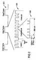
- Fig. 2schematically represents a modulation scheme used by RC5 codes.
- a remote control signal generated using RC5comprises a series of data frames 210.
- Each data frame 210comprises a command word 220 consisting of 14 bits.
- the structure of this command word 220is indicated in Fig. 2 .
- Each bit 230comprises 32 pulses at a frequency of 36 kHz.
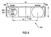
- Fig. 3schematically represents a side view of an IR transceiver package 310, in which the described hybrid transceiver can be housed.
- Fig. 4schematically represents the same package from above.
- emitter 320 and receiver 330are provided at either end of the package 310, with a shield 340 separating the emitter lens 320 and the receiver lens 330.
- the emitter 320houses not only an IR LED (840 nm) 324 but also a remote control LED (940 nm) 322.
- the profile of the emitter lens 320is not modified to accommodate the remote control LED.
- the two LEDs 322, 324are accurately positioned with respect to the optical axis of the emitter lens 320, to achieve a suitable viewing angle at a receiver.
- the electrical circuit supporting the two transmittersis configured so that the operating current through each LED 322, 324 is appropriate. This configuration assists in producing a relatively low-power IrDA transceiver and a standard remote control transmitter.
- Each package of the designed componentalso includes sufficient heat sink material around the two LEDs 322, 324 to achieve sufficient thermal dissipation.
- Fig. 5schematically represents electrical circuitry 510 supporting the two transmitters incorporated in the package 310 of Figs. 3 and 4 .
- This circuitry 510is based upon a HSDL 3000 Stargate platform, which is selected for a lower idle current specification, and as this component is qualified at a relatively high operating current.
- the transceiver circuitry 510comprises transmitter circuitry 520 and receiver circuitry 530, which respectively support the operation of the two transmitter LEDs 322, 324 and the receiver photodiode 332.
- Fig. 6schematically represents switching circuitry external to the transceiver circuitry 510 of Fig. 5 .
- Independent inputs 522, 524are provided for respective transmitting LEDs 322, 324.
- the advantages of this represented configurationare that (i) data can be transmitted using one or both LEDs 322, 324, and (ii) operating currents can be independently configured for each LED 322, 324.
- the described hybrid transceiveris suited to remote control transmission in a bi-directional mode.
- a usercan activate an appliance from an held-hand remote control, and the appliance transmits back to the held hand remote control a menu of possible selections to the user. Examples of such selections include temperature and humidity settings from an air conditioner, a song list from a compact disc player, lighting controls from a multimedia device. The user can select an desired choice from the menu, and then transmits this selection to the appliance.
- the receiver circuitry of the IrDA receiveris used to receive and interpret data from the remotely controlled appliance.
- the IrDA receiveris not particularly selective, and can interpret remote control frequency signals centred around 940 nm.
- a particular advantage of using an IrDA transceiver for bi-directional remote controlis that the transceiver receiver circuitry follows a similar logic to that required for bi-directional remote control functionality.
- the presence of lightprovides a "low” signal output and the absence of light provides a "high” signal output.
- the IR transmittercan provide a digitized output by receiving a remote control bit pattern, which obviates the need for an external digitizer.
- the IrDA transceiveralso incorporates ambient light filtering, which is also suitable for receiving a remote control data signal.
Landscapes
- Physics & Mathematics (AREA)
- Electromagnetism (AREA)
- Engineering & Computer Science (AREA)
- Computer Networks & Wireless Communication (AREA)
- Signal Processing (AREA)
- Optical Communication System (AREA)
- Selective Calling Equipment (AREA)
Description
- The present invention relates to optical transceiver devices used for data transfer and control applications.
- An infrared (IR) transceiver module typically comprises an IR light emitting diode (LED) operating at 870 nm and a photodiode, packaged together with appropriate supporting circuitry to form a self-contained unit.
- Electrical terminals are exposed on the outside of the self-contained unit to enable electrical coupling to external circuitry. To facilitate use of the unit, the light output from the LED illuminates a large area (typically a cone of +/- 15°). Consequently, a user need not precisely align the transmitter and receiver.
- By combining various components of an IR transceiver into a single package, the size and form factor of the transceiver can be considerably reduced. Further, the package is typically more durable and may consume less power than equivalent transceivers comprising discrete components. IR transceivers are used extensively in a wide variety of consumer and personal electronic appliances, such as cellular telephones, personal digital assistants and laptop computers. Such appliances typically include an IR transmitting window, which is referred to as a "cosmetic window".
- An example of an optical transceiver device is disclosed in
US 6 014 236 A . The optical transceiver device disclosed herein includes a pair of transceivers, with each transceiver being housed under two separate lenses, i.e., at least one transmitter and receiver are housed under each lens. In one embodiment, at least one of the transceivers is a dual wavelength transceiver and includes a pair of transmitters. Accordingly, in this embodiment, at least two transmitters and two receivers are housed under a first lens and at least one transmitter and a receiver are housed under a second lens. - Another example of an optical transceiver device is disclosed in
JP 2001244498 - The Infrared Data Association (IrDA) is an industry organization that promotes international standards for hardware and software used in IR communication links. Most IR communications functionality included in consumer and personal appliances conforms with IrDA specifications.
Fig. 1 schematically represents an example of two IrDA-compliant devices communicating via an IR link.Device A 110 communicates withdevice B 120 viaIR link 130. - When an IR link communication channel is created between two IR transceiver modules, the LED in the first transceiver optically couples with the photodiode in the second transceiver. Further, the LED in the second transceiver optically couples with the photodiode in the first transceiver. Although IR transceivers using IR frequency bands are commonly used, other frequency bands can also be used. The IR transceiver module is deeply mounted on an end portion of a main printed circuit board (PCB). This transceiver module comprises a main body having a moulded lens shape over the LED and the photodiode.
- An optical transceiver device is described herein for combining the functions of IrDa-compliant infrared transceivers and remote control devices. A receiver of the transceiver allows the remote control facilities of the transceiver to encompass bi-directional remote control capabilities.
- The described optical transceiver includes an IR transmitter, operating around a first frequency band, that transforms electric signals into transmitted optical signals in IrDA-compliant infrared communications; a remote control transmitter, operating around a second frequency band different from said first frequency band, that transforms electrical signals into transmitted optical signals in remote control applications; and an IR receiver, operating around the first frequency band, that transforms into electric signals optical signals received in the first frequency band in IrDA-compliant infrared communications. The IR transmitter and the remote control transmitter can independently transmit data, and the receiver can receive data from a corresponding IR transmitter operating in said first frequency band. The optical device is characterized in that said IR transmitter and said remote control transmitter are housed within a same emitter lens to achieve a desired viewing angle; and only said IR receiver is housed within a separate receiver lens.
- It is to be noted that hereon in, the IR transmitter and the remote control transmitter are referred to as the first and second transmitters, respectively, while the IR receiver is referred to as the first receiver.
- The first transmitter can be used for IrDA-compliant infrared communications, and the second transmitter can be used for remote control applications. For instance, the first frequency band may be approximately 805 nm to 900nm, and the second frequency band is approximately 915 nm to 965 nm. The receiver may not be particularly selective and, as a result, is able to detect remote control signals transmitted in the second frequency band.
- The first transmitter and the second transmitter preferably include respective light emitting diodes, which are both within a transmitter lens to achieve a desired viewing angle. The receiver may then comprise a photodiode. The first transmitter and the second transmitter are usefully formed on a single integrated circuit.
Fig. 1 is a schematic representation of infrared communication between two devices.Fig. 2 is a schematic representation of an example of a communication protocol for remote control communication.Fig. 3 is a schematic representation of a side view of a housing for an optical transceiver described herein.Fig. 4 is a schematic representation of the housing ofFig. 3 , as viewed from above.Fig. 5 is an electrical circuit schematic representation of circuitry for an optical transceiver described herein, housed in the housing ofFigs. 3 and4 .Fig. 6 is an electrical circuit schematic representation of switching circuitry external to the configuration represented inFig. 5 .- An optical transceiver that combines functionality for IrDA-compliant infrared communications and remote control infrared communications is described herein. An overview of remote control communications is provided, followed by a comparison of infrared and remote control communications. The hybrid optical transceiver that combines these respective facilities is then described in detail, together with possible applications for this hybrid transceiver.
- A remote control transmitter comprises an IR LED (operating at 940 nm), which is electrically connected to a switching transistor and a battery supply. When a key is pressed on a handheld remote control unit, a predetermined pulse pattern is generated. This pulse pattern is activated by a transistor, and the LED is consequently activated. An IR signal from the LED is received by a remote control receiver (in, for example, an appliance), and the encoded function communicated by the pulsed pattern is decoded.
- Communication using remote control devices is uni-directional. There is no common standard for remote control coding. RC5 code is one remote control code.
Fig. 2 schematically represents a modulation scheme used by RC5 codes. A remote control signal generated using RC5 comprises a series ofdata frames 210. Eachdata frame 210 comprises acommand word 220 consisting of 14 bits. The structure of thiscommand word 220 is indicated inFig. 2 . Eachbit 230 comprises 32 pulses at a frequency of 36 kHz. - Many remote receivers have a relatively narrow spectral reception band centred around 940 nm. Such receivers are not able to receive IR emission from IrDA-compliant transceivers operating at 870 nm reliably.
- Table 1 below tabulates, in comparative form, the difference between various parameters of typical remote control systems, and IrDA-compliant systems.
TABLE 1 Remote Control IrDA Wavelength (nm) 915-965 805-900 Transmission Unidirectional Bi-directional Frame format Proprietory for each vendor Defined by IrDA Modulation Bi-Phase, Pulse length, and Pulse Distance RZI, 3-16 duration Receiver sensitivity 0.05 µW/cm2 4µW/cm2 Link Distance 8m (typical) 1 m Transmit Angle +/- 20° +/- 15° Carrier Frequency 30-60 khz Receiver bandwidth Carrier Freq +/- 2kHz Wide bandwidth Data Rate 2000-4000bps 2.4bps-16Mbps - These two IR schemes are relatively similar, though these schemes are not compatible with each other and consequently cannot inter-operate.
Fig. 3 schematically represents a side view of anIR transceiver package 310, in which the described hybrid transceiver can be housed.Fig. 4 schematically represents the same package from above. With reference toFigs. 3 and4 ,emitter 320 andreceiver 330 are provided at either end of thepackage 310, with ashield 340 separating theemitter lens 320 and thereceiver lens 330. Theemitter 320 houses not only an IR LED (840 nm) 324 but also a remote control LED (940 nm) 322. The profile of theemitter lens 320 is not modified to accommodate the remote control LED.- The two
LEDs emitter lens 320, to achieve a suitable viewing angle at a receiver. - The electrical circuit supporting the two transmitters is configured so that the operating current through each
LED LEDs Fig. 5 schematically representselectrical circuitry 510 supporting the two transmitters incorporated in thepackage 310 ofFigs. 3 and4 . Thiscircuitry 510 is based upon a HSDL 3000 Stargate platform, which is selected for a lower idle current specification, and as this component is qualified at a relatively high operating current. Thetransceiver circuitry 510 comprisestransmitter circuitry 520 andreceiver circuitry 530, which respectively support the operation of the twotransmitter LEDs receiver photodiode 332.Fig. 6 schematically represents switching circuitry external to thetransceiver circuitry 510 ofFig. 5 .Independent inputs LEDs LEDs LED - The described hybrid transceiver is suited to remote control transmission in a bi-directional mode. For example, a user can activate an appliance from an held-hand remote control, and the appliance transmits back to the held hand remote control a menu of possible selections to the user. Examples of such selections include temperature and humidity settings from an air conditioner, a song list from a compact disc player, lighting controls from a multimedia device. The user can select an desired choice from the menu, and then transmits this selection to the appliance.
- In this case, the receiver circuitry of the IrDA receiver is used to receive and interpret data from the remotely controlled appliance. The IrDA receiver is not particularly selective, and can interpret remote control frequency signals centred around 940 nm.
- A particular advantage of using an IrDA transceiver for bi-directional remote control is that the transceiver receiver circuitry follows a similar logic to that required for bi-directional remote control functionality. The presence of light provides a "low" signal output and the absence of light provides a "high" signal output. Thus, the IR transmitter can provide a digitized output by receiving a remote control bit pattern, which obviates the need for an external digitizer. The IrDA transceiver also incorporates ambient light filtering, which is also suitable for receiving a remote control data signal.
- Various exemplary relative measurements and circuitry are shown in the representations. These are exemplary and not limiting on the broadest aspect of the invention.
- Various alterations and modifications can be made to the arrangements and techniques described herein, as would be apparent to one skilled in the relevant art.
Claims (8)
- An optical transceiver device (310), comprising:an IR transmitter (324), operating around a first frequency band, that transforms electric signals into transmitted optical signals in IrDA-compliant infrared communications;a remote control transmitter (322), operating around a second frequency band different from said first frequency band, that transforms electrical signals into transmitted optical signals in remote control applications; andan IR receiver (332), operating around the first frequency band, that transforms into electric signals optical signals received in the first frequency band in IrDA-compliant infrared communications;wherein the IR transmitter (324) and the remote control transmitter (322) can independently transmit data, and the receiver (332) can receive data from a corresponding IR transmitter operating in said first frequency band,
characterized in that
said IR transmitter (324) and said remote control transmitter (322) are housed within a common emitter lens (320) to achieve a desired viewing angle; and
only said IR receiver (332) is housed within a separate receiver lens (330). - The transceiver device (310,) as claimed in claim 1, wherein the IR transmitter (324) and the remote control transmitter (322) comprise respective light emitting diodes (324, 322).
- The transceiver device (310) as claimed in claim 1 or 2, wherein the IR transmitter (324) and the remote control transmitter (322) are formed on a single integrated circuit.
- The transceiver device (310,) as claimed in any one of the preceding claims, further comprising transmitter circuitry (520) for supplying a modulated electrical signal to the IR transmitter.
- The transceiver device (310) as claimed in any one of the preceding claims, wherein the IR receiver (332,) comprises a photodiode (332).
- The transceiver device (310) as claimed in any one of the preceding claims, wherein the first frequency band is approximately 805 nm to 900nm, and the second frequency band is approximately 915 nm to 965 nm.
- The transceiver device (310) as claimed in any one of the preceding claims, further comprising a shield (340) between said transmitter lens (320) and said receiver lens (330).
- The transceiver device (310) as claimed in any one of the preceding claims, wherein the IR receiver (332) is further operable to receive signals in the second frequency band and transform them into electrical signals.
Applications Claiming Priority (2)
| Application Number | Priority Date | Filing Date | Title |
|---|---|---|---|
| SG200201560ASG114535A1 (en) | 2002-03-14 | 2002-03-14 | Optical transceiver for data transfer and control applications |
| SG200201560 | 2002-03-14 |
Publications (3)
| Publication Number | Publication Date |
|---|---|
| EP1345341A2 EP1345341A2 (en) | 2003-09-17 |
| EP1345341A3 EP1345341A3 (en) | 2003-10-29 |
| EP1345341B1true EP1345341B1 (en) | 2008-03-05 |
Family
ID=27765020
Family Applications (1)
| Application Number | Title | Priority Date | Filing Date |
|---|---|---|---|
| EP02026191AExpired - LifetimeEP1345341B1 (en) | 2002-03-14 | 2002-11-25 | Optical transceiver for data transfer and control applications |
Country Status (5)
| Country | Link |
|---|---|
| US (1) | US20040213576A1 (en) |
| EP (1) | EP1345341B1 (en) |
| JP (1) | JP2003283434A (en) |
| DE (1) | DE60225417T2 (en) |
| SG (1) | SG114535A1 (en) |
Cited By (2)
| Publication number | Priority date | Publication date | Assignee | Title |
|---|---|---|---|---|
| US8090309B2 (en) | 2004-10-27 | 2012-01-03 | Chestnut Hill Sound, Inc. | Entertainment system with unified content selection |
| US8355690B2 (en) | 2004-10-27 | 2013-01-15 | Chestnut Hill Sound, Inc. | Electrical and mechanical connector adaptor system for media devices |
Families Citing this family (21)
| Publication number | Priority date | Publication date | Assignee | Title |
|---|---|---|---|---|
| FI116431B (en)* | 2003-12-16 | 2005-11-15 | Pancomp Electronics Oy | Control and user interface of an electronic device |
| US7474857B2 (en) | 2004-07-21 | 2009-01-06 | Zilog, Inc. | Recovering energy from an IrDA/remote control transmitter circuit |
| US7509057B2 (en) | 2004-02-25 | 2009-03-24 | Zilog, Inc. | IrDA transceiver module that also functions as remote control IR transmitter |
| WO2005083914A2 (en)* | 2004-02-25 | 2005-09-09 | Zilog, Inc. | Recovering energy from an irda/remote control transmitter circuit |
| US8682168B2 (en) | 2004-07-21 | 2014-03-25 | Ixys Ch Gmbh | Recovering energy from an IrDA/remote control transmitter circuit |
| US20190278560A1 (en) | 2004-10-27 | 2019-09-12 | Chestnut Hill Sound, Inc. | Media appliance with auxiliary source module docking and fail-safe alarm modes |
| US20070003289A1 (en)* | 2005-06-30 | 2007-01-04 | Wee-Sin Tan | Integrated infrared transceiver |
| US7633076B2 (en) | 2005-09-30 | 2009-12-15 | Apple Inc. | Automated response to and sensing of user activity in portable devices |
| US7714265B2 (en) | 2005-09-30 | 2010-05-11 | Apple Inc. | Integrated proximity sensor and light sensor |
| CN101026413B (en)* | 2006-02-17 | 2012-01-04 | 华为技术有限公司 | Lighting light wireless communication system |
| JP4690240B2 (en)* | 2006-04-27 | 2011-06-01 | シャープ株式会社 | Remote control system |
| US8543002B1 (en) | 2006-05-19 | 2013-09-24 | Ixys Ch Gmbh | Controlling transmission power in an IrDA/RC transmitter circuit |
| JP4428403B2 (en)* | 2006-06-28 | 2010-03-10 | ソニー株式会社 | Infrared signal receiver, liquid crystal display and optical element |
| US8006002B2 (en) | 2006-12-12 | 2011-08-23 | Apple Inc. | Methods and systems for automatic configuration of peripherals |
| US8031164B2 (en)* | 2007-01-05 | 2011-10-04 | Apple Inc. | Backlight and ambient light sensor system |
| US8698727B2 (en)* | 2007-01-05 | 2014-04-15 | Apple Inc. | Backlight and ambient light sensor system |
| US7957762B2 (en)* | 2007-01-07 | 2011-06-07 | Apple Inc. | Using ambient light sensor to augment proximity sensor output |
| US8693877B2 (en)* | 2007-03-09 | 2014-04-08 | Apple Inc. | Integrated infrared receiver and emitter for multiple functionalities |
| US9146304B2 (en) | 2012-09-10 | 2015-09-29 | Apple Inc. | Optical proximity sensor with ambient light and temperature compensation |
| KR102126566B1 (en)* | 2013-11-04 | 2020-06-24 | 삼성전자주식회사 | Infrared ray communication method of electronic apparatus and electronic appparatus thereof |
| FR3066339A1 (en)* | 2017-05-11 | 2018-11-16 | Thales | FSOI COMPACT MODULE RESISTANT TO SEVERE ENVIRONMENTS |
Family Cites Families (14)
| Publication number | Priority date | Publication date | Assignee | Title |
|---|---|---|---|---|
| US5167020A (en)* | 1989-05-25 | 1992-11-24 | The Boeing Company | Serial data transmitter with dual buffers operating separately and having scan and self test modes |
| JP3161910B2 (en)* | 1994-07-26 | 2001-04-25 | シャープ株式会社 | Communication device |
| JPH08248277A (en)* | 1995-01-09 | 1996-09-27 | Fujitsu Ltd | Optical device |
| US5699105A (en)* | 1995-09-28 | 1997-12-16 | Lucent Technologies Inc. | Curbside circuitry for interactive communication services |
| CA2166255C (en)* | 1995-12-28 | 2001-12-18 | John V. Taglione | Multi-channel optical transceiver |
| FI106332B (en)* | 1996-12-30 | 2001-01-15 | Nokia Mobile Phones Ltd | Infrared link |
| US5761350A (en)* | 1997-01-22 | 1998-06-02 | Koh; Seungug | Method and apparatus for providing a seamless electrical/optical multi-layer micro-opto-electro-mechanical system assembly |
| US6014236A (en)* | 1997-02-04 | 2000-01-11 | Digital Equipment Corporation | Optical broadcast communication |
| JP3512990B2 (en)* | 1997-09-16 | 2004-03-31 | 株式会社東芝 | Communication network system, relay terminal of communication network system, and communication control method of network system |
| US20010005197A1 (en)* | 1998-12-21 | 2001-06-28 | Animesh Mishra | Remotely controlling electronic devices |
| IL132711A (en)* | 1999-11-03 | 2005-05-17 | Elpas Electro Optic Systems Lt | Dual rf/ir communication device and method of use thereof |
| AU2001253760A1 (en)* | 2000-04-21 | 2001-11-07 | Teraconnect, Inc. | Precision grid standoff for optical components on opto-electronic devices |
| KR100885466B1 (en)* | 2000-11-23 | 2009-02-24 | 코닌클리케 필립스 일렉트로닉스 엔.브이. | Apparatus comprising a remote control device and a first electronic device |
| US6977915B2 (en)* | 2001-01-30 | 2005-12-20 | Nortel Networks Limited | Method and system for controlling device transmit power in a wireless communication network |
- 2002
- 2002-03-14SGSG200201560Apatent/SG114535A1/enunknown
- 2002-11-25EPEP02026191Apatent/EP1345341B1/ennot_activeExpired - Lifetime
- 2002-11-25DEDE60225417Tpatent/DE60225417T2/ennot_activeExpired - Lifetime
- 2003
- 2003-01-07USUS10/337,757patent/US20040213576A1/ennot_activeAbandoned
- 2003-02-25JPJP2003047890Apatent/JP2003283434A/enactivePending
Cited By (5)
| Publication number | Priority date | Publication date | Assignee | Title |
|---|---|---|---|---|
| US8090309B2 (en) | 2004-10-27 | 2012-01-03 | Chestnut Hill Sound, Inc. | Entertainment system with unified content selection |
| US8355690B2 (en) | 2004-10-27 | 2013-01-15 | Chestnut Hill Sound, Inc. | Electrical and mechanical connector adaptor system for media devices |
| US8725063B2 (en) | 2004-10-27 | 2014-05-13 | Chestnut Hill Sound, Inc. | Multi-mode media device using metadata to access media content |
| US8843092B2 (en) | 2004-10-27 | 2014-09-23 | Chestnut Hill Sound, Inc. | Method and apparatus for accessing media content via metadata |
| US10114608B2 (en) | 2004-10-27 | 2018-10-30 | Chestnut Hill Sound, Inc. | Multi-mode media device operable in first and second modes, selectively |
Also Published As
| Publication number | Publication date |
|---|---|
| DE60225417D1 (en) | 2008-04-17 |
| EP1345341A2 (en) | 2003-09-17 |
| SG114535A1 (en) | 2005-09-28 |
| US20040213576A1 (en) | 2004-10-28 |
| DE60225417T2 (en) | 2009-04-09 |
| EP1345341A3 (en) | 2003-10-29 |
| JP2003283434A (en) | 2003-10-03 |
Similar Documents
| Publication | Publication Date | Title |
|---|---|---|
| EP1345341B1 (en) | Optical transceiver for data transfer and control applications | |
| KR101366623B1 (en) | Rf communication module and rf communication system | |
| EP1673882B1 (en) | An improved communication link for communicating data | |
| US7663501B2 (en) | Apparatus and method of controlling emitting color of visible light according to a current communication state in a VLC device | |
| JP4409579B2 (en) | RF communication system | |
| US20090185809A1 (en) | Irda transceiver module that also functions as remote control IR transmitter | |
| US20070003289A1 (en) | Integrated infrared transceiver | |
| GB2391370A (en) | An integrated wireless pointer device with integral laser pointer | |
| JP4477427B2 (en) | Light emitting / receiving electronic components | |
| JP2005123818A (en) | Radio communication apparatus | |
| KR101379968B1 (en) | Apparatus, system and method for communicating data using light | |
| JP2003163633A (en) | Remote data communication system, remote data transmitter and remote data receiver | |
| CN210199979U (en) | Novel self-copying remote controller circuit | |
| KR100386565B1 (en) | Mobile terminal having remote controller and remote controlling method using the same | |
| EP1078480B1 (en) | A device and method for wireless data transmission | |
| JP5327679B2 (en) | Remote control device | |
| KR0136895B1 (en) | Remote power control system | |
| KR200313838Y1 (en) | remote control system of remote-control | |
| KR20080033591A (en) | IDD module capable of receiving remote control signals | |
| KR20020076742A (en) | Mobile communication terminal having remote control feature | |
| WO2023186727A1 (en) | A li-fi and wireless power transmission enabled portless device | |
| KR19980062836U (en) | Loss Prevention Transceiver | |
| AU2002100371A4 (en) | Wireless remote-control light adjuster | |
| KR200286900Y1 (en) | remote control system using the remote-controller | |
| KR20050099156A (en) | Battery module transceiver of ir communication apparatus |
Legal Events
| Date | Code | Title | Description |
|---|---|---|---|
| PUAI | Public reference made under article 153(3) epc to a published international application that has entered the european phase | Free format text:ORIGINAL CODE: 0009012 | |
| PUAL | Search report despatched | Free format text:ORIGINAL CODE: 0009013 | |
| AK | Designated contracting states | Kind code of ref document:A2 Designated state(s):AT BE BG CH CY CZ DE DK EE ES FI FR GB GR IE IT LI LU MC NL PT SE SK TR | |
| AX | Request for extension of the european patent | Extension state:AL LT LV MK RO SI | |
| AK | Designated contracting states | Kind code of ref document:A3 Designated state(s):AT BE BG CH CY CZ DE DK EE ES FI FR GB GR IE IT LI LU MC NL PT SE SK TR | |
| AX | Request for extension of the european patent | Extension state:AL LT LV MK RO SI | |
| 17P | Request for examination filed | Effective date:20040205 | |
| AKX | Designation fees paid | Designated state(s):DE FR GB | |
| 17Q | First examination report despatched | Effective date:20050602 | |
| 17Q | First examination report despatched | Effective date:20050602 | |
| RAP1 | Party data changed (applicant data changed or rights of an application transferred) | Owner name:AVAGO TECHNOLOGIES ECBU IP (SINGAPORE) PTE. LTD. | |
| GRAP | Despatch of communication of intention to grant a patent | Free format text:ORIGINAL CODE: EPIDOSNIGR1 | |
| GRAS | Grant fee paid | Free format text:ORIGINAL CODE: EPIDOSNIGR3 | |
| GRAA | (expected) grant | Free format text:ORIGINAL CODE: 0009210 | |
| AK | Designated contracting states | Kind code of ref document:B1 Designated state(s):DE FR GB | |
| REG | Reference to a national code | Ref country code:GB Ref legal event code:FG4D | |
| REF | Corresponds to: | Ref document number:60225417 Country of ref document:DE Date of ref document:20080417 Kind code of ref document:P | |
| ET | Fr: translation filed | ||
| PLBE | No opposition filed within time limit | Free format text:ORIGINAL CODE: 0009261 | |
| STAA | Information on the status of an ep patent application or granted ep patent | Free format text:STATUS: NO OPPOSITION FILED WITHIN TIME LIMIT | |
| REG | Reference to a national code | Ref country code:GB Ref legal event code:732E | |
| 26N | No opposition filed | Effective date:20081208 | |
| REG | Reference to a national code | Ref country code:FR Ref legal event code:TP | |
| PGFP | Annual fee paid to national office [announced via postgrant information from national office to epo] | Ref country code:GB Payment date:20121120 Year of fee payment:11 | |
| PGFP | Annual fee paid to national office [announced via postgrant information from national office to epo] | Ref country code:FR Payment date:20121220 Year of fee payment:11 | |
| PGFP | Annual fee paid to national office [announced via postgrant information from national office to epo] | Ref country code:DE Payment date:20121130 Year of fee payment:11 | |
| REG | Reference to a national code | Ref country code:DE Ref legal event code:R119 Ref document number:60225417 Country of ref document:DE | |
| GBPC | Gb: european patent ceased through non-payment of renewal fee | Effective date:20131125 | |
| REG | Reference to a national code | Ref country code:DE Ref legal event code:R079 Ref document number:60225417 Country of ref document:DE Free format text:PREVIOUS MAIN CLASS: H04B0010100000 Ipc:H04B0010110000 | |
| REG | Reference to a national code | Ref country code:FR Ref legal event code:ST Effective date:20140731 | |
| REG | Reference to a national code | Ref country code:DE Ref legal event code:R119 Ref document number:60225417 Country of ref document:DE Effective date:20140603 Ref country code:DE Ref legal event code:R079 Ref document number:60225417 Country of ref document:DE Free format text:PREVIOUS MAIN CLASS: H04B0010100000 Ipc:H04B0010110000 Effective date:20140723 | |
| PG25 | Lapsed in a contracting state [announced via postgrant information from national office to epo] | Ref country code:DE Free format text:LAPSE BECAUSE OF NON-PAYMENT OF DUE FEES Effective date:20140603 | |
| PG25 | Lapsed in a contracting state [announced via postgrant information from national office to epo] | Ref country code:GB Free format text:LAPSE BECAUSE OF NON-PAYMENT OF DUE FEES Effective date:20131125 Ref country code:FR Free format text:LAPSE BECAUSE OF NON-PAYMENT OF DUE FEES Effective date:20131202 |