EP1341119A2 - Iris recognition system - Google Patents
Iris recognition systemDownload PDFInfo
- Publication number
- EP1341119A2 EP1341119A2EP03003239AEP03003239AEP1341119A2EP 1341119 A2EP1341119 A2EP 1341119A2EP 03003239 AEP03003239 AEP 03003239AEP 03003239 AEP03003239 AEP 03003239AEP 1341119 A2EP1341119 A2EP 1341119A2
- Authority
- EP
- European Patent Office
- Prior art keywords
- light
- user
- iris recognition
- led
- recognition system
- Prior art date
- Legal status (The legal status is an assumption and is not a legal conclusion. Google has not performed a legal analysis and makes no representation as to the accuracy of the status listed.)
- Granted
Links
Images


Classifications
- G—PHYSICS
- G06—COMPUTING OR CALCULATING; COUNTING
- G06V—IMAGE OR VIDEO RECOGNITION OR UNDERSTANDING
- G06V40/00—Recognition of biometric, human-related or animal-related patterns in image or video data
- G06V40/10—Human or animal bodies, e.g. vehicle occupants or pedestrians; Body parts, e.g. hands
- G06V40/18—Eye characteristics, e.g. of the iris
- G06V40/19—Sensors therefor
- G—PHYSICS
- G06—COMPUTING OR CALCULATING; COUNTING
- G06V—IMAGE OR VIDEO RECOGNITION OR UNDERSTANDING
- G06V40/00—Recognition of biometric, human-related or animal-related patterns in image or video data
- G06V40/60—Static or dynamic means for assisting the user to position a body part for biometric acquisition
- G06V40/67—Static or dynamic means for assisting the user to position a body part for biometric acquisition by interactive indications to the user
- A—HUMAN NECESSITIES
- A61—MEDICAL OR VETERINARY SCIENCE; HYGIENE
- A61B—DIAGNOSIS; SURGERY; IDENTIFICATION
- A61B3/00—Apparatus for testing the eyes; Instruments for examining the eyes
- A61B3/10—Objective types, i.e. instruments for examining the eyes independent of the patients' perceptions or reactions
- A61B3/12—Objective types, i.e. instruments for examining the eyes independent of the patients' perceptions or reactions for looking at the eye fundus, e.g. ophthalmoscopes
- A61B3/1216—Objective types, i.e. instruments for examining the eyes independent of the patients' perceptions or reactions for looking at the eye fundus, e.g. ophthalmoscopes for diagnostics of the iris
- A—HUMAN NECESSITIES
- A61—MEDICAL OR VETERINARY SCIENCE; HYGIENE
- A61B—DIAGNOSIS; SURGERY; IDENTIFICATION
- A61B3/00—Apparatus for testing the eyes; Instruments for examining the eyes
- A61B3/10—Objective types, i.e. instruments for examining the eyes independent of the patients' perceptions or reactions
- A61B3/14—Arrangements specially adapted for eye photography
- A61B3/15—Arrangements specially adapted for eye photography with means for aligning, spacing or blocking spurious reflection ; with means for relaxing
- A61B3/152—Arrangements specially adapted for eye photography with means for aligning, spacing or blocking spurious reflection ; with means for relaxing for aligning
Definitions
- the second stepincludes the sub-steps of: emitting a light from at least one light emitter (i.e. LED) as the user approaches the iris recognition system; allowing the user to see a chip LED light when the user looks into the reflector unit, namely cold mirror, perpendicularly; and diffusing the LED light through a diffusion sheet and passing it through the mask.
- a light emitteri.e. LED
- the hole mask and the lensare placed close to the focal length of the lens.
- the motion region of the eyeis determined.
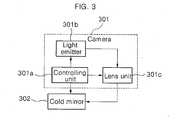
- the cold mirror 208reflects all wavelength bands except for the wavelength of LED among visible rays that have passed through, and passes through infrared rays.
- the usersees his/her own eye through the cold mirror and at the same time the LED light behind the cold mirror.
Landscapes
- Engineering & Computer Science (AREA)
- Human Computer Interaction (AREA)
- Physics & Mathematics (AREA)
- General Physics & Mathematics (AREA)
- Multimedia (AREA)
- Theoretical Computer Science (AREA)
- Health & Medical Sciences (AREA)
- General Health & Medical Sciences (AREA)
- Ophthalmology & Optometry (AREA)
- Measurement Of The Respiration, Hearing Ability, Form, And Blood Characteristics Of Living Organisms (AREA)
- Eye Examination Apparatus (AREA)
- Image Input (AREA)
Abstract
Description
Claims (14)
- An iris recognition system, comprising:a board including a controller for controlling emission of light;a light emitter mounted on the board for emitting a light and uniformly scattering andequalizing the intensity of the emitted light;a lens unit for maintaining a focal length of the emitted light from the light emitter,refracting and converging the light at a constant angle, and passing the light through apredetermined portion only so as to display a position where a user's eye is should be; anda reflector unit for reflecting every wavelength band that passed through the lens unitexcept for a wavelength of a predetermined light.
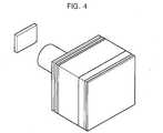
- The system according to claim 1, wherein the light emitter comprises a chipLED including a plurality of infrared ray LEDs and a diffusion sheet for uniformly diffusingthe emitted light.
- The system according to claim 1 or 2, wherein the lens unit consists ofcircular-shaped lenses in form of LED mounted on the chip LED to be able to convergeeach LED light.
- The system according to claim 3, wherein both ends of each LED lens are cutoff to prevent refraction at tangential parts where the lenses of each LED are connected,whereby a plurality of lenses can be connected to each other.
- The system according to at lease one of the preceding claims, wherein the lightemitter further comprises a hole mask for passing the light only through a predeterminedpart and equalizing intensity of the light passed through.
- The system according to at least one of the preceding claims, wherein the lensunit further comprises a tube for keeping the light from the light emitter at a predetermineddistance to focus the light.
- The system according to at least one of the preceding claims, wherein the lensunit further comprises an instruction slit for manifesting a converged light in form of variousmasked patterns.
- The system according to claim 7, wherein the instructions shown on thereflector unit, namely cold mirror, are masked patterns, each pattern indicating a distance tothe user.
- The system according to at least one of the preceding claims, wherein the lensunit for converging the light comprises a lens for performing at least one of refraction andconvergence of the light at a predetermined angle to enable the user to see the light with oneeye only.
- The system according to at least one of the preceding claims, wherein the usercan see an emitted light from the light emitter, namely LED, only when the user sees thereflector unit, namely cold mirror, at a predetermined angle.
- The system according to at least one of the preceding claims, wherein the lensunit comprises a reflector unit for reflecting every wavelength band except for a wavelengthof the light emitted from the LED among visible rays of the light that passed through thelens, and passing infrared rays.
- A method of recognizing an iris, comprising:(1) pluralizing a distance between a user and an iris recognition system;(2) if the user approaches the iris recognition system, emitting a light from at least onelight emitter, and passing the light through a diffuser and a mask;(3) allowing the user to see the refracted light from the lens;(4) showing various instruction patterns in accordance with a view angle of the usertoward a reflector unit or a distance between the user and the iris recognition system; and(5)adjusting the distance from the user to the iris recognition system following theinstructions manifested on the refractor unit.
- The method according to claim 12, where the second step comprises thesub-steps of:emitting a light from at least one light emitter as the user approaches the irisrecognition system;displaying a chip LED light only when the user looks into the reflector unit, namelycold mirror, perpendicularly; anddiffusing the LED light through a diffusion sheet and passing the same through themask.
- The method according to claim 12 or 13, wherein the third or fourth stepcomprises the sub-steps of:passing the masked light through a tube for maintaining a focal length;collecting the light through the lens' refraction to enable the user to see the refractorunit with only one eye; anddisplaying various instruction patterns in accordance with a view angle of the usertoward a reflector unit or a distance between the user and the iris recognition system.
Applications Claiming Priority (2)
| Application Number | Priority Date | Filing Date | Title |
|---|---|---|---|
| KR1020020009216AKR100842501B1 (en) | 2002-02-21 | 2002-02-21 | Eye position indicator of iris recognition system |
| KR2002009216 | 2002-02-21 |
Publications (3)
| Publication Number | Publication Date |
|---|---|
| EP1341119A2true EP1341119A2 (en) | 2003-09-03 |
| EP1341119A3 EP1341119A3 (en) | 2004-05-26 |
| EP1341119B1 EP1341119B1 (en) | 2006-09-13 |
Family
ID=27725800
Family Applications (1)
| Application Number | Title | Priority Date | Filing Date |
|---|---|---|---|
| EP03003239AExpired - LifetimeEP1341119B1 (en) | 2002-02-21 | 2003-02-21 | Iris recognition system |
Country Status (6)
| Country | Link |
|---|---|
| US (1) | US20030156741A1 (en) |
| EP (1) | EP1341119B1 (en) |
| KR (1) | KR100842501B1 (en) |
| CN (1) | CN1275186C (en) |
| CA (1) | CA2419312A1 (en) |
| DE (1) | DE60308245T2 (en) |
Cited By (5)
| Publication number | Priority date | Publication date | Assignee | Title |
|---|---|---|---|---|
| WO2008124382A1 (en)* | 2007-04-03 | 2008-10-16 | Honeywell International Inc. | Agile illumination for biometric authentication |
| WO2013034803A1 (en)* | 2011-09-06 | 2013-03-14 | Icare Finland Oy | Ophthalmic apparatus and method for measuring an eye |
| EP2669843A3 (en)* | 2012-05-29 | 2015-04-15 | Fujitsu Limited | Imaging device and electronic apparatus |
| EP2953057A1 (en)* | 2014-06-03 | 2015-12-09 | IRIS ID, Inc. | Iris recognition terminal and method |
| DE102017110818A1 (en) | 2017-05-18 | 2018-11-22 | Osram Opto Semiconductors Gmbh | Iris recognition system |
Families Citing this family (38)
| Publication number | Priority date | Publication date | Assignee | Title |
|---|---|---|---|---|
| KR20030082128A (en)* | 2002-04-16 | 2003-10-22 | 엘지전자 주식회사 | System of mouse include iris recognition of pc |
| US7796784B2 (en)* | 2002-11-07 | 2010-09-14 | Panasonic Corporation | Personal authentication method for certificating individual iris |
| WO2005002441A1 (en)* | 2003-07-04 | 2005-01-13 | Matsushita Electric Industrial Co., Ltd. | Organism eye judgment method and organism eye judgment device |
| KR100557037B1 (en)* | 2003-09-01 | 2006-03-03 | 엘지전자 주식회사 | Eye position indicator of iris recognition system |
| US8098901B2 (en) | 2005-01-26 | 2012-01-17 | Honeywell International Inc. | Standoff iris recognition system |
| US7761453B2 (en) | 2005-01-26 | 2010-07-20 | Honeywell International Inc. | Method and system for indexing and searching an iris image database |
| US8090157B2 (en) | 2005-01-26 | 2012-01-03 | Honeywell International Inc. | Approaches and apparatus for eye detection in a digital image |
| US7593550B2 (en) | 2005-01-26 | 2009-09-22 | Honeywell International Inc. | Distance iris recognition |
| US8064647B2 (en) | 2006-03-03 | 2011-11-22 | Honeywell International Inc. | System for iris detection tracking and recognition at a distance |
| US8442276B2 (en) | 2006-03-03 | 2013-05-14 | Honeywell International Inc. | Invariant radial iris segmentation |
| US8705808B2 (en) | 2003-09-05 | 2014-04-22 | Honeywell International Inc. | Combined face and iris recognition system |
| FR2860629B1 (en)* | 2003-10-01 | 2005-12-02 | Sagem | DEVICE FOR POSITIONING A USER BY REPERAGE ON BOTH EYES |
| CN1326084C (en)* | 2005-03-24 | 2007-07-11 | 上海邦震科技发展有限公司 | Non-contact type self-feedback iris image acquisition device |
| FR2897966B1 (en)* | 2006-02-24 | 2008-05-16 | Sagem Defense Securite | CONTACTLESS BIODETECTOR |
| WO2007101276A1 (en) | 2006-03-03 | 2007-09-07 | Honeywell International, Inc. | Single lens splitter camera |
| DE602007007062D1 (en) | 2006-03-03 | 2010-07-22 | Honeywell Int Inc | IRISER IDENTIFICATION SYSTEM WITH IMAGE QUALITY METERING |
| AU2007281940B2 (en) | 2006-03-03 | 2010-12-16 | Gentex Corporation | Modular biometrics collection system architecture |
| WO2007101275A1 (en) | 2006-03-03 | 2007-09-07 | Honeywell International, Inc. | Camera with auto-focus capability |
| WO2008019169A2 (en) | 2006-03-03 | 2008-02-14 | Honeywell International, Inc. | Iris encoding system |
| KR100876821B1 (en)* | 2007-02-12 | 2009-01-09 | 삼성전자주식회사 | Device for capturing face images accurately within the shooting area |
| US8063889B2 (en) | 2007-04-25 | 2011-11-22 | Honeywell International Inc. | Biometric data collection system |
| US8436907B2 (en) | 2008-05-09 | 2013-05-07 | Honeywell International Inc. | Heterogeneous video capturing system |
| US8213782B2 (en) | 2008-08-07 | 2012-07-03 | Honeywell International Inc. | Predictive autofocusing system |
| US8090246B2 (en) | 2008-08-08 | 2012-01-03 | Honeywell International Inc. | Image acquisition system |
| US8280119B2 (en) | 2008-12-05 | 2012-10-02 | Honeywell International Inc. | Iris recognition system using quality metrics |
| US8472681B2 (en) | 2009-06-15 | 2013-06-25 | Honeywell International Inc. | Iris and ocular recognition system using trace transforms |
| US8630464B2 (en) | 2009-06-15 | 2014-01-14 | Honeywell International Inc. | Adaptive iris matching using database indexing |
| KR101001338B1 (en)* | 2009-08-24 | 2010-12-14 | 씨엠아이텍주식회사 | Identification device |
| US8742887B2 (en) | 2010-09-03 | 2014-06-03 | Honeywell International Inc. | Biometric visitor check system |
| KR101833034B1 (en) | 2012-01-19 | 2018-02-27 | 브이아이디 스케일, 인크. | Methods and systems for video delivery supporting adaption to viewing conditions |
| KR102023611B1 (en) | 2012-05-04 | 2019-09-23 | 삼성전자 주식회사 | Terminal and method for iris scanning and proximity sensing |
| US10045050B2 (en) | 2014-04-25 | 2018-08-07 | Vid Scale, Inc. | Perceptual preprocessing filter for viewing-conditions-aware video coding |
| US9928422B2 (en)* | 2014-10-15 | 2018-03-27 | Samsung Electronics Co., Ltd. | User terminal apparatus and IRIS recognition method thereof |
| KR102305997B1 (en) | 2014-11-17 | 2021-09-28 | 엘지이노텍 주식회사 | Iris recognition camera system, terminal including the same and iris recognition method using the system |
| CN107390853B (en)* | 2017-06-26 | 2020-11-06 | Oppo广东移动通信有限公司 | electronic device |
| CN110211260A (en)* | 2019-04-23 | 2019-09-06 | 江西理工大学 | A kind of system and method carrying out intelligent recognition using optical information |
| CN113378708B (en)* | 2021-06-10 | 2024-02-13 | 西北民族大学 | Miniature iris recognition system and iris recognition mechanism for mobile communication equipment |
| FI130761B1 (en)* | 2022-02-10 | 2024-02-29 | Optomed Oyj | Ophthalmic apparatus and alignment method |
Family Cites Families (17)
| Publication number | Priority date | Publication date | Assignee | Title |
|---|---|---|---|---|
| JP2987450B2 (en)* | 1990-05-08 | 1999-12-06 | 八木 聰明 | Eye movement measurement device |
| US5291560A (en)* | 1991-07-15 | 1994-03-01 | Iri Scan Incorporated | Biometric personal identification system based on iris analysis |
| US6079830A (en)* | 1992-08-31 | 2000-06-27 | Canon Kabushiki Kaisha | Eye measuring apparatus having signal processing means for calculating eye information |
| US5433197A (en) | 1992-09-04 | 1995-07-18 | Stark; Edward W. | Non-invasive glucose measurement method and apparatus |
| US5572596A (en) | 1994-09-02 | 1996-11-05 | David Sarnoff Research Center, Inc. | Automated, non-invasive iris recognition system and method |
| JPH08266476A (en)* | 1995-03-30 | 1996-10-15 | Nippon Koden Corp | Eye movement measuring device |
| US20020122572A1 (en)* | 1996-06-06 | 2002-09-05 | Christopher H. Seal | Personal identification |
| DE69830306T2 (en)* | 1997-03-03 | 2006-02-02 | British Telecommunications P.L.C. | DEVICE FOR SAFETY TESTING |
| EP0910986A1 (en)* | 1997-10-24 | 1999-04-28 | BRITISH TELECOMMUNICATIONS public limited company | Imaging apparatus |
| US6289113B1 (en)* | 1998-11-25 | 2001-09-11 | Iridian Technologies, Inc. | Handheld iris imaging apparatus and method |
| US6377699B1 (en)* | 1998-11-25 | 2002-04-23 | Iridian Technologies, Inc. | Iris imaging telephone security module and method |
| US6532298B1 (en)* | 1998-11-25 | 2003-03-11 | Iridian Technologies, Inc. | Portable authentication device and method using iris patterns |
| KR100320465B1 (en)* | 1999-01-11 | 2002-01-16 | 구자홍 | Iris recognition system |
| KR100320188B1 (en)* | 1999-03-23 | 2002-01-10 | 구자홍 | Forgery judgment method for iris recognition system |
| US6480219B1 (en)* | 1999-07-21 | 2002-11-12 | Fuji Photo Film Co., Ltd. | Exposure head |
| KR100582052B1 (en)* | 1999-09-03 | 2006-05-23 | 엘지전자 주식회사 | Iris recognition device |
| KR100649303B1 (en)* | 2000-11-16 | 2006-11-24 | 엘지전자 주식회사 | Iris image butler device of both eyes |
- 2002
- 2002-02-21KRKR1020020009216Apatent/KR100842501B1/ennot_activeExpired - Lifetime
- 2003
- 2003-02-20CACA002419312Apatent/CA2419312A1/ennot_activeAbandoned
- 2003-02-20USUS10/368,388patent/US20030156741A1/ennot_activeAbandoned
- 2003-02-21CNCNB031061923Apatent/CN1275186C/ennot_activeExpired - Lifetime
- 2003-02-21DEDE60308245Tpatent/DE60308245T2/ennot_activeExpired - Lifetime
- 2003-02-21EPEP03003239Apatent/EP1341119B1/ennot_activeExpired - Lifetime
Cited By (11)
| Publication number | Priority date | Publication date | Assignee | Title |
|---|---|---|---|---|
| WO2008124382A1 (en)* | 2007-04-03 | 2008-10-16 | Honeywell International Inc. | Agile illumination for biometric authentication |
| GB2462018A (en)* | 2007-04-03 | 2010-01-27 | Honeywell Int Inc | Agile illumination for biometric authentication |
| GB2462018B (en)* | 2007-04-03 | 2012-01-11 | Honeywell Int Inc | Agile illumination for biometric authentication |
| WO2013034803A1 (en)* | 2011-09-06 | 2013-03-14 | Icare Finland Oy | Ophthalmic apparatus and method for measuring an eye |
| US9332901B2 (en) | 2011-09-06 | 2016-05-10 | Icare Finland Oy | Ophthalmic apparatus and method for measuring an eye |
| EP2669843A3 (en)* | 2012-05-29 | 2015-04-15 | Fujitsu Limited | Imaging device and electronic apparatus |
| EP2953057A1 (en)* | 2014-06-03 | 2015-12-09 | IRIS ID, Inc. | Iris recognition terminal and method |
| KR20150139374A (en)* | 2014-06-03 | 2015-12-11 | (주)아이리스아이디 | Apparutus for scanning the iris and method thereof |
| US9454698B2 (en) | 2014-06-03 | 2016-09-27 | Iris Id, Inc | Iris recognition terminal and method |
| DE102017110818A1 (en) | 2017-05-18 | 2018-11-22 | Osram Opto Semiconductors Gmbh | Iris recognition system |
| WO2018211082A1 (en) | 2017-05-18 | 2018-11-22 | Osram Opto Semiconductors Gmbh | System for iris recognition |
Also Published As
| Publication number | Publication date |
|---|---|
| CN1275186C (en) | 2006-09-13 |
| CN1439998A (en) | 2003-09-03 |
| EP1341119B1 (en) | 2006-09-13 |
| KR100842501B1 (en) | 2008-07-01 |
| US20030156741A1 (en) | 2003-08-21 |
| EP1341119A3 (en) | 2004-05-26 |
| CA2419312A1 (en) | 2003-08-21 |
| DE60308245T2 (en) | 2006-12-28 |
| DE60308245D1 (en) | 2006-10-26 |
| KR20030070184A (en) | 2003-08-29 |
Similar Documents
| Publication | Publication Date | Title |
|---|---|---|
| EP1341119B1 (en) | Iris recognition system | |
| US7095901B2 (en) | Apparatus and method for adjusting focus position in iris recognition system | |
| US7271839B2 (en) | Display device of focal angle and focal distance in iris recognition system | |
| US7200248B2 (en) | Eye image pickup apparatus and entry/leave management system | |
| KR20030056781A (en) | Iris recording and recognition method using of several led for iris recognition system | |
| JP2007319174A (en) | Imaging device and authentication device using the same | |
| KR20150028430A (en) | Iris recognized system for automatically adjusting focusing of the iris and the method thereof | |
| KR100447403B1 (en) | Focusing angle and distance display in iris recognition system | |
| KR100430268B1 (en) | Focusing angle display of iris recognition system | |
| KR100434370B1 (en) | Focusing distance measurement in iris recognition system | |
| KR100557037B1 (en) | Eye position indicator of iris recognition system | |
| JP2007209646A (en) | Guide device, photographing device, authentication device, and guide method | |
| KR100410972B1 (en) | Focusing distance display of iris recognition system | |
| WO2002007068A1 (en) | An authentication device for forming an image of at least a partial area of an eye retina | |
| KR20170000023U (en) | Iris identifying device having optical filter optimized on taking iris image | |
| KR100880466B1 (en) | Pupil Detection Using Red-eye in the Iris Recognition System | |
| KR100547333B1 (en) | How to display the distance of the iris system | |
| KR20030091173A (en) | Optical input device for iris recognition | |
| KR20050094221A (en) | Automatic tilt optical unit and the method for iris recognition system | |
| KR20050000154A (en) | Apparatus for acquiring an iris image | |
| KR20050103562A (en) | Indicated device for iris recognized system | |
| KR20050088563A (en) | System for iris recognized using of visible light and the method | |
| KR20090106793A (en) | Apparatus and method for iris recognition for others using viewfinder | |
| KR20050088564A (en) | System for iris recognized using of exterior light interception filter | |
| KR20050094222A (en) | Focus distance measuerment method for optical reflection in iris recognized system |
Legal Events
| Date | Code | Title | Description |
|---|---|---|---|
| PUAI | Public reference made under article 153(3) epc to a published international application that has entered the european phase | Free format text:ORIGINAL CODE: 0009012 | |
| AK | Designated contracting states | Kind code of ref document:A2 Designated state(s):AT BE BG CH CY CZ DE DK EE ES FI FR GB GR HU IE IT LI LU MC NL PT SE SI SK TR | |
| AX | Request for extension of the european patent | Extension state:AL LT LV MK RO | |
| PUAL | Search report despatched | Free format text:ORIGINAL CODE: 0009013 | |
| AK | Designated contracting states | Kind code of ref document:A3 Designated state(s):AT BE BG CH CY CZ DE DK EE ES FI FR GB GR HU IE IT LI LU MC NL PT SE SI SK TR | |
| AX | Request for extension of the european patent | Extension state:AL LT LV MK RO | |
| RIC1 | Information provided on ipc code assigned before grant | Ipc:7G 06K 9/20 B Ipc:7G 06K 9/00 A | |
| 17P | Request for examination filed | Effective date:20040823 | |
| AKX | Designation fees paid | Designated state(s):DE FR GB IT | |
| 17Q | First examination report despatched | Effective date:20050405 | |
| GRAP | Despatch of communication of intention to grant a patent | Free format text:ORIGINAL CODE: EPIDOSNIGR1 | |
| GRAS | Grant fee paid | Free format text:ORIGINAL CODE: EPIDOSNIGR3 | |
| GRAA | (expected) grant | Free format text:ORIGINAL CODE: 0009210 | |
| AK | Designated contracting states | Kind code of ref document:B1 Designated state(s):DE FR GB IT | |
| PG25 | Lapsed in a contracting state [announced via postgrant information from national office to epo] | Ref country code:IT Free format text:LAPSE BECAUSE OF FAILURE TO SUBMIT A TRANSLATION OF THE DESCRIPTION OR TO PAY THE FEE WITHIN THE PRESCRIBED TIME-LIMIT;WARNING: LAPSES OF ITALIAN PATENTS WITH EFFECTIVE DATE BEFORE 2007 MAY HAVE OCCURRED AT ANY TIME BEFORE 2007. THE CORRECT EFFECTIVE DATE MAY BE DIFFERENT FROM THE ONE RECORDED. Effective date:20060913 | |
| REG | Reference to a national code | Ref country code:GB Ref legal event code:FG4D | |
| REF | Corresponds to: | Ref document number:60308245 Country of ref document:DE Date of ref document:20061026 Kind code of ref document:P | |
| ET | Fr: translation filed | ||
| PLBE | No opposition filed within time limit | Free format text:ORIGINAL CODE: 0009261 | |
| STAA | Information on the status of an ep patent application or granted ep patent | Free format text:STATUS: NO OPPOSITION FILED WITHIN TIME LIMIT | |
| 26N | No opposition filed | Effective date:20070614 | |
| REG | Reference to a national code | Ref country code:GB Ref legal event code:732E Free format text:REGISTERED BETWEEN 20100610 AND 20100616 | |
| REG | Reference to a national code | Ref country code:FR Ref legal event code:TP | |
| REG | Reference to a national code | Ref country code:FR Ref legal event code:PLFP Year of fee payment:14 | |
| REG | Reference to a national code | Ref country code:FR Ref legal event code:PLFP Year of fee payment:15 | |
| REG | Reference to a national code | Ref country code:FR Ref legal event code:PLFP Year of fee payment:16 | |
| REG | Reference to a national code | Ref country code:DE Ref legal event code:R079 Ref document number:60308245 Country of ref document:DE Free format text:PREVIOUS MAIN CLASS: G06K0009000000 Ipc:G06V0010000000 | |
| PGFP | Annual fee paid to national office [announced via postgrant information from national office to epo] | Ref country code:FR Payment date:20211223 Year of fee payment:20 Ref country code:GB Payment date:20211220 Year of fee payment:20 | |
| PGFP | Annual fee paid to national office [announced via postgrant information from national office to epo] | Ref country code:DE Payment date:20211220 Year of fee payment:20 | |
| PGFP | Annual fee paid to national office [announced via postgrant information from national office to epo] | Ref country code:IT Payment date:20211221 Year of fee payment:20 | |
| REG | Reference to a national code | Ref country code:DE Ref legal event code:R071 Ref document number:60308245 Country of ref document:DE | |
| REG | Reference to a national code | Ref country code:GB Ref legal event code:PE20 Expiry date:20230220 | |
| PG25 | Lapsed in a contracting state [announced via postgrant information from national office to epo] | Ref country code:GB Free format text:LAPSE BECAUSE OF EXPIRATION OF PROTECTION Effective date:20230220 |