EP1340473A2 - Heart valve replacement using flexible tubes - Google Patents
Heart valve replacement using flexible tubesDownload PDFInfo
- Publication number
- EP1340473A2 EP1340473A2EP03075347AEP03075347AEP1340473A2EP 1340473 A2EP1340473 A2EP 1340473A2EP 03075347 AEP03075347 AEP 03075347AEP 03075347 AEP03075347 AEP 03075347AEP 1340473 A2EP1340473 A2EP 1340473A2
- Authority
- EP
- European Patent Office
- Prior art keywords
- valve
- tissue
- valves
- heart
- replacement
- Prior art date
- Legal status (The legal status is an assumption and is not a legal conclusion. Google has not performed a legal analysis and makes no representation as to the accuracy of the status listed.)
- Withdrawn
Links
- 210000003709heart valveAnatomy0.000titleclaimsabstractdescription95
- 239000000463materialSubstances0.000claimsabstractdescription42
- 238000002513implantationMethods0.000claimsabstractdescription19
- 210000002216heartAnatomy0.000claimsdescription74
- 238000004519manufacturing processMethods0.000claimsdescription19
- 230000003014reinforcing effectEffects0.000claimsdescription7
- 230000004044responseEffects0.000claimsdescription6
- 210000003516pericardiumAnatomy0.000claimsdescription3
- 210000001519tissueAnatomy0.000abstractdescription291
- 230000000968intestinal effectEffects0.000abstractdescription89
- 238000000034methodMethods0.000abstractdescription83
- 210000003540papillary muscleAnatomy0.000abstractdescription55
- 241001465754MetazoaSpecies0.000abstractdescription35
- 238000013459approachMethods0.000abstractdescription20
- 210000001367arteryAnatomy0.000abstractdescription16
- 210000000813small intestineAnatomy0.000abstractdescription13
- 238000007675cardiac surgeryMethods0.000abstractdescription7
- 230000000747cardiac effectEffects0.000abstractdescription6
- 230000002685pulmonary effectEffects0.000abstractdescription6
- 210000004115mitral valveAnatomy0.000description81
- 230000006870functionEffects0.000description80
- 210000001765aortic valveAnatomy0.000description64
- 210000000591tricuspid valveAnatomy0.000description46
- 230000002861ventricularEffects0.000description35
- 210000000709aortaAnatomy0.000description33
- 210000004369bloodAnatomy0.000description28
- 239000008280bloodSubstances0.000description28
- 210000003102pulmonary valveAnatomy0.000description26
- 210000001147pulmonary arteryAnatomy0.000description23
- 229920002994synthetic fiberPolymers0.000description23
- 208000004434CalcinosisDiseases0.000description19
- 230000002308calcificationEffects0.000description19
- SXRSQZLOMIGNAQ-UHFFFAOYSA-NGlutaraldehydeChemical compoundO=CCCCC=OSXRSQZLOMIGNAQ-UHFFFAOYSA-N0.000description17
- 210000005240left ventricleAnatomy0.000description15
- 210000003698chordae tendineaeAnatomy0.000description14
- 238000013461designMethods0.000description14
- 239000000126substanceSubstances0.000description14
- 208000007536ThrombosisDiseases0.000description13
- 230000008569processEffects0.000description12
- 239000007858starting materialSubstances0.000description12
- 229920001971elastomerPolymers0.000description11
- 238000001356surgical procedureMethods0.000description11
- 230000008901benefitEffects0.000description10
- 210000005246left atriumAnatomy0.000description10
- 210000001015abdomenAnatomy0.000description9
- 230000008602contractionEffects0.000description9
- 238000004132cross linkingMethods0.000description9
- 230000007774longtermEffects0.000description9
- 238000012360testing methodMethods0.000description9
- 241000283690Bos taurusSpecies0.000description8
- 102000008186CollagenHuman genes0.000description8
- 108010035532CollagenProteins0.000description8
- 241000282412HomoSpecies0.000description8
- 210000003484anatomyAnatomy0.000description8
- 230000017531blood circulationEffects0.000description8
- 229920001436collagenPolymers0.000description8
- 238000010276constructionMethods0.000description8
- 239000012530fluidSubstances0.000description8
- 210000005241right ventricleAnatomy0.000description8
- 210000002837heart atriumAnatomy0.000description7
- 230000008439repair processEffects0.000description7
- 238000009958sewingMethods0.000description7
- IJGRMHOSHXDMSA-UHFFFAOYSA-NAtomic nitrogenChemical compoundN#NIJGRMHOSHXDMSA-UHFFFAOYSA-N0.000description6
- 241000282887SuidaeSpecies0.000description6
- 210000000038chestAnatomy0.000description6
- 238000011161developmentMethods0.000description6
- 230000018109developmental processEffects0.000description6
- 238000004090dissolutionMethods0.000description6
- 239000000806elastomerSubstances0.000description6
- 241000282898Sus scrofaSpecies0.000description5
- 230000003187abdominal effectEffects0.000description5
- 230000002159abnormal effectEffects0.000description5
- 230000005856abnormalityEffects0.000description5
- 238000009826distributionMethods0.000description5
- 239000004744fabricSubstances0.000description5
- 239000000835fiberSubstances0.000description5
- 238000003306harvestingMethods0.000description5
- 230000000004hemodynamic effectEffects0.000description5
- 230000000774hypoallergenic effectEffects0.000description5
- 230000036512infertilityEffects0.000description5
- 229920001343polytetrafluoroethylenePolymers0.000description5
- 239000004810polytetrafluoroethyleneSubstances0.000description5
- 241000894007speciesSpecies0.000description5
- 230000009885systemic effectEffects0.000description5
- 210000004291uterusAnatomy0.000description5
- 208000031481Pathologic ConstrictionDiseases0.000description4
- 206010067171RegurgitationDiseases0.000description4
- FAPWRFPIFSIZLT-UHFFFAOYSA-MSodium chlorideChemical compound[Na+].[Cl-]FAPWRFPIFSIZLT-UHFFFAOYSA-M0.000description4
- 238000004458analytical methodMethods0.000description4
- 239000003146anticoagulant agentSubstances0.000description4
- 230000010100anticoagulationEffects0.000description4
- 230000000890antigenic effectEffects0.000description4
- 230000001746atrial effectEffects0.000description4
- 210000004027cellAnatomy0.000description4
- 230000002950deficientEffects0.000description4
- 230000000694effectsEffects0.000description4
- 238000003780insertionMethods0.000description4
- 230000037431insertionEffects0.000description4
- 239000007788liquidSubstances0.000description4
- 230000033001locomotionEffects0.000description4
- 210000004072lungAnatomy0.000description4
- 230000003278mimic effectEffects0.000description4
- 210000000056organAnatomy0.000description4
- 229920003023plasticPolymers0.000description4
- 238000011160researchMethods0.000description4
- 239000011780sodium chlorideSubstances0.000description4
- 230000036262stenosisEffects0.000description4
- 208000037804stenosisDiseases0.000description4
- 210000004876tela submucosaAnatomy0.000description4
- 238000009966trimmingMethods0.000description4
- 241000282472Canis lupus familiarisSpecies0.000description3
- 229920000544Gore-TexPolymers0.000description3
- 206010018910HaemolysisDiseases0.000description3
- 208000032843HemorrhageDiseases0.000description3
- 230000001580bacterial effectEffects0.000description3
- 210000002469basement membraneAnatomy0.000description3
- 210000004556brainAnatomy0.000description3
- 230000035602clottingEffects0.000description3
- 239000011248coating agentSubstances0.000description3
- 238000000576coating methodMethods0.000description3
- 238000005520cutting processMethods0.000description3
- 238000000502dialysisMethods0.000description3
- 208000037265diseases, disorders, signs and symptomsDiseases0.000description3
- 238000002474experimental methodMethods0.000description3
- 238000007710freezingMethods0.000description3
- 230000008014freezingEffects0.000description3
- 230000008588hemolysisEffects0.000description3
- 210000003734kidneyAnatomy0.000description3
- 210000003205muscleAnatomy0.000description3
- 229910052757nitrogenInorganic materials0.000description3
- 239000004033plasticSubstances0.000description3
- 230000035935pregnancyEffects0.000description3
- 230000009467reductionEffects0.000description3
- 230000002829reductive effectEffects0.000description3
- 210000005245right atriumAnatomy0.000description3
- 210000002460smooth muscleAnatomy0.000description3
- 238000003860storageMethods0.000description3
- 208000035143Bacterial infectionDiseases0.000description2
- 206010010356Congenital anomalyDiseases0.000description2
- 206010017533Fungal infectionDiseases0.000description2
- 241000282537Mandrillus sphinxSpecies0.000description2
- 208000031888MycosesDiseases0.000description2
- 239000004677NylonSubstances0.000description2
- 241001494479PecoraSpecies0.000description2
- 239000004809TeflonSubstances0.000description2
- 229920006362Teflon®Polymers0.000description2
- RTAQQCXQSZGOHL-UHFFFAOYSA-NTitaniumChemical compound[Ti]RTAQQCXQSZGOHL-UHFFFAOYSA-N0.000description2
- 230000002411adverseEffects0.000description2
- 208000022362bacterial infectious diseaseDiseases0.000description2
- 230000009286beneficial effectEffects0.000description2
- 230000000740bleeding effectEffects0.000description2
- 238000004422calculation algorithmMethods0.000description2
- 230000002612cardiopulmonary effectEffects0.000description2
- 210000000748cardiovascular systemAnatomy0.000description2
- 238000012790confirmationMethods0.000description2
- 230000008828contractile functionEffects0.000description2
- 239000003431cross linking reagentSubstances0.000description2
- 230000003205diastolic effectEffects0.000description2
- 201000010099diseaseDiseases0.000description2
- 230000010102embolizationEffects0.000description2
- 210000002889endothelial cellAnatomy0.000description2
- 210000000109fascia lataAnatomy0.000description2
- 230000008175fetal developmentEffects0.000description2
- 206010020871hypertrophic cardiomyopathyDiseases0.000description2
- 239000007943implantSubstances0.000description2
- 238000000338in vitroMethods0.000description2
- 208000014674injuryDiseases0.000description2
- 230000007246mechanismEffects0.000description2
- 229920001778nylonPolymers0.000description2
- 230000036407painEffects0.000description2
- 230000002093peripheral effectEffects0.000description2
- 238000002360preparation methodMethods0.000description2
- 229920000260silasticPolymers0.000description2
- 239000000243solutionSubstances0.000description2
- 239000000758substrateSubstances0.000description2
- BFKJFAAPBSQJPD-UHFFFAOYSA-NtetrafluoroetheneChemical compoundFC(F)=C(F)FBFKJFAAPBSQJPD-UHFFFAOYSA-N0.000description2
- 230000002885thrombogenetic effectEffects0.000description2
- 239000010936titaniumSubstances0.000description2
- 229910052719titaniumInorganic materials0.000description2
- 230000008733traumaEffects0.000description2
- 230000002792vascularEffects0.000description2
- 238000011179visual inspectionMethods0.000description2
- 241000894006BacteriaSpecies0.000description1
- OKTJSMMVPCPJKN-UHFFFAOYSA-NCarbonChemical compound[C]OKTJSMMVPCPJKN-UHFFFAOYSA-N0.000description1
- 208000032170Congenital AbnormalitiesDiseases0.000description1
- 102000004190EnzymesHuman genes0.000description1
- 108090000790EnzymesProteins0.000description1
- 241001272720Medialuna californiensisSpecies0.000description1
- 208000020128Mitral stenosisDiseases0.000description1
- 206010027727Mitral valve incompetenceDiseases0.000description1
- 208000012868OvergrowthDiseases0.000description1
- 241000282520PapioSpecies0.000description1
- 241000237509Patinopecten sp.Species0.000description1
- 206010037448Pulmonary valve incompetenceDiseases0.000description1
- 206010037451Pulmonary valve stenosis congenitalDiseases0.000description1
- 208000035415ReinfectionDiseases0.000description1
- NINIDFKCEFEMDL-UHFFFAOYSA-NSulfurChemical compound[S]NINIDFKCEFEMDL-UHFFFAOYSA-N0.000description1
- 208000002847Surgical WoundDiseases0.000description1
- 201000001943Tricuspid Valve InsufficiencyDiseases0.000description1
- 206010044642Tricuspid valve stenosisDiseases0.000description1
- 201000008803Wolff-Parkinson-white syndromeDiseases0.000description1
- 230000001154acute effectEffects0.000description1
- 230000004075alterationEffects0.000description1
- 238000012443analytical studyMethods0.000description1
- 230000003466anti-cipated effectEffects0.000description1
- 201000006800aortic valve disease 1Diseases0.000description1
- 230000004872arterial blood pressureEffects0.000description1
- 239000012237artificial materialSubstances0.000description1
- QVGXLLKOCUKJST-UHFFFAOYSA-Natomic oxygenChemical compound[O]QVGXLLKOCUKJST-UHFFFAOYSA-N0.000description1
- 238000010009beatingMethods0.000description1
- 210000000601blood cellAnatomy0.000description1
- 230000023555blood coagulationEffects0.000description1
- 230000036772blood pressureEffects0.000description1
- 230000036770blood supplyEffects0.000description1
- 238000009395breedingMethods0.000description1
- 230000001488breeding effectEffects0.000description1
- 238000004364calculation methodMethods0.000description1
- 229910052799carbonInorganic materials0.000description1
- 210000005242cardiac chamberAnatomy0.000description1
- 230000010261cell growthEffects0.000description1
- 238000012993chemical processingMethods0.000description1
- 238000006243chemical reactionMethods0.000description1
- 238000004140cleaningMethods0.000description1
- 238000005094computer simulationMethods0.000description1
- 208000016569congenital mitral valve insufficiencyDiseases0.000description1
- 208000021250congenital pulmonary valve stenosisDiseases0.000description1
- 210000002808connective tissueAnatomy0.000description1
- 210000001608connective tissue cellAnatomy0.000description1
- 239000000470constituentSubstances0.000description1
- 210000004351coronary vesselAnatomy0.000description1
- 230000008878couplingEffects0.000description1
- 238000010168coupling processMethods0.000description1
- 238000005859coupling reactionMethods0.000description1
- 238000012258culturingMethods0.000description1
- 230000006378damageEffects0.000description1
- 230000003412degenerative effectEffects0.000description1
- 230000006866deteriorationEffects0.000description1
- 230000035487diastolic blood pressureEffects0.000description1
- 230000001079digestive effectEffects0.000description1
- LOKCTEFSRHRXRJ-UHFFFAOYSA-Idipotassium trisodium dihydrogen phosphate hydrogen phosphate dichlorideChemical compoundP(=O)(O)(O)[O-].[K+].P(=O)(O)([O-])[O-].[Na+].[Na+].[Cl-].[K+].[Cl-].[Na+]LOKCTEFSRHRXRJ-UHFFFAOYSA-I0.000description1
- 208000035475disorderDiseases0.000description1
- 229940079593drugDrugs0.000description1
- 239000003814drugSubstances0.000description1
- 230000002183duodenal effectEffects0.000description1
- 238000002297emergency surgeryMethods0.000description1
- 229910001651emeryInorganic materials0.000description1
- 238000005516engineering processMethods0.000description1
- 210000002919epithelial cellAnatomy0.000description1
- 238000011156evaluationMethods0.000description1
- 210000002458fetal heartAnatomy0.000description1
- 210000003754fetusAnatomy0.000description1
- 238000011049fillingMethods0.000description1
- 125000001153fluoro groupChemical groupF*0.000description1
- 230000002538fungal effectEffects0.000description1
- 238000002695general anesthesiaMethods0.000description1
- 238000010353genetic engineeringMethods0.000description1
- 208000019622heart diseaseDiseases0.000description1
- 230000004217heart functionEffects0.000description1
- 230000002949hemolytic effectEffects0.000description1
- 230000002962histologic effectEffects0.000description1
- 229910052739hydrogenInorganic materials0.000description1
- 239000001257hydrogenSubstances0.000description1
- 125000004435hydrogen atomChemical class[H]*0.000description1
- 238000001727in vivoMethods0.000description1
- 208000015181infectious diseaseDiseases0.000description1
- 238000013101initial testMethods0.000description1
- 230000003993interactionEffects0.000description1
- 210000000936intestineAnatomy0.000description1
- 150000002500ionsChemical class0.000description1
- 238000002386leachingMethods0.000description1
- 201000003453lung abscessDiseases0.000description1
- 230000007257malfunctionEffects0.000description1
- 239000011159matrix materialSubstances0.000description1
- 238000005259measurementMethods0.000description1
- 229910052751metalInorganic materials0.000description1
- 239000002184metalSubstances0.000description1
- 208000005907mitral valve insufficiencyDiseases0.000description1
- 208000006887mitral valve stenosisDiseases0.000description1
- 238000012986modificationMethods0.000description1
- 230000004048modificationEffects0.000description1
- 238000000465mouldingMethods0.000description1
- 230000001453nonthrombogenic effectEffects0.000description1
- 238000010899nucleationMethods0.000description1
- 229910052760oxygenInorganic materials0.000description1
- 239000001301oxygenSubstances0.000description1
- 238000006213oxygenation reactionMethods0.000description1
- 230000036961partial effectEffects0.000description1
- 230000001575pathological effectEffects0.000description1
- 230000007170pathologyEffects0.000description1
- 230000037361pathwayEffects0.000description1
- 239000002953phosphate buffered salineSubstances0.000description1
- 230000035479physiological effects, processes and functionsEffects0.000description1
- 239000004014plasticizerSubstances0.000description1
- 238000006116polymerization reactionMethods0.000description1
- -1polytetrafluoroethylenePolymers0.000description1
- 230000002980postoperative effectEffects0.000description1
- 239000003761preservation solutionSubstances0.000description1
- 239000003755preservative agentSubstances0.000description1
- 238000003825pressingMethods0.000description1
- 102000004169proteins and genesHuman genes0.000description1
- 108090000623proteins and genesProteins0.000description1
- 201000010298pulmonary valve insufficiencyDiseases0.000description1
- 238000005086pumpingMethods0.000description1
- 239000002296pyrolytic carbonSubstances0.000description1
- 230000003252repetitive effectEffects0.000description1
- 230000002441reversible effectEffects0.000description1
- 201000003068rheumatic feverDiseases0.000description1
- 235000020637scallopNutrition0.000description1
- 229920002379silicone rubberPolymers0.000description1
- 239000004945silicone rubberSubstances0.000description1
- 210000002027skeletal muscleAnatomy0.000description1
- 230000002269spontaneous effectEffects0.000description1
- 238000010561standard procedureMethods0.000description1
- 210000002784stomachAnatomy0.000description1
- 229910052717sulfurInorganic materials0.000description1
- 239000011593sulfurSubstances0.000description1
- 238000010189synthetic methodMethods0.000description1
- 230000001839systemic circulationEffects0.000description1
- 230000008719thickeningEffects0.000description1
- 238000012090tissue culture techniqueMethods0.000description1
- 230000025594tube developmentEffects0.000description1
- 230000007306turnoverEffects0.000description1
- 210000001835visceraAnatomy0.000description1
Images


Classifications
- A—HUMAN NECESSITIES
- A61—MEDICAL OR VETERINARY SCIENCE; HYGIENE
- A61F—FILTERS IMPLANTABLE INTO BLOOD VESSELS; PROSTHESES; DEVICES PROVIDING PATENCY TO, OR PREVENTING COLLAPSING OF, TUBULAR STRUCTURES OF THE BODY, e.g. STENTS; ORTHOPAEDIC, NURSING OR CONTRACEPTIVE DEVICES; FOMENTATION; TREATMENT OR PROTECTION OF EYES OR EARS; BANDAGES, DRESSINGS OR ABSORBENT PADS; FIRST-AID KITS
- A61F2/00—Filters implantable into blood vessels; Prostheses, i.e. artificial substitutes or replacements for parts of the body; Appliances for connecting them with the body; Devices providing patency to, or preventing collapsing of, tubular structures of the body, e.g. stents
- A61F2/0095—Packages or dispensers for prostheses or other implants
- A—HUMAN NECESSITIES
- A61—MEDICAL OR VETERINARY SCIENCE; HYGIENE
- A61F—FILTERS IMPLANTABLE INTO BLOOD VESSELS; PROSTHESES; DEVICES PROVIDING PATENCY TO, OR PREVENTING COLLAPSING OF, TUBULAR STRUCTURES OF THE BODY, e.g. STENTS; ORTHOPAEDIC, NURSING OR CONTRACEPTIVE DEVICES; FOMENTATION; TREATMENT OR PROTECTION OF EYES OR EARS; BANDAGES, DRESSINGS OR ABSORBENT PADS; FIRST-AID KITS
- A61F2/00—Filters implantable into blood vessels; Prostheses, i.e. artificial substitutes or replacements for parts of the body; Appliances for connecting them with the body; Devices providing patency to, or preventing collapsing of, tubular structures of the body, e.g. stents
- A61F2/02—Prostheses implantable into the body
- A61F2/24—Heart valves ; Vascular valves, e.g. venous valves; Heart implants, e.g. passive devices for improving the function of the native valve or the heart muscle; Transmyocardial revascularisation [TMR] devices; Valves implantable in the body
- A61F2/2412—Heart valves ; Vascular valves, e.g. venous valves; Heart implants, e.g. passive devices for improving the function of the native valve or the heart muscle; Transmyocardial revascularisation [TMR] devices; Valves implantable in the body with soft flexible valve members, e.g. tissue valves shaped like natural valves
- A—HUMAN NECESSITIES
- A61—MEDICAL OR VETERINARY SCIENCE; HYGIENE
- A61L—METHODS OR APPARATUS FOR STERILISING MATERIALS OR OBJECTS IN GENERAL; DISINFECTION, STERILISATION OR DEODORISATION OF AIR; CHEMICAL ASPECTS OF BANDAGES, DRESSINGS, ABSORBENT PADS OR SURGICAL ARTICLES; MATERIALS FOR BANDAGES, DRESSINGS, ABSORBENT PADS OR SURGICAL ARTICLES
- A61L27/00—Materials for grafts or prostheses or for coating grafts or prostheses
- A61L27/36—Materials for grafts or prostheses or for coating grafts or prostheses containing ingredients of undetermined constitution or reaction products thereof, e.g. transplant tissue, natural bone, extracellular matrix
- A61L27/3604—Materials for grafts or prostheses or for coating grafts or prostheses containing ingredients of undetermined constitution or reaction products thereof, e.g. transplant tissue, natural bone, extracellular matrix characterised by the human or animal origin of the biological material, e.g. hair, fascia, fish scales, silk, shellac, pericardium, pleura, renal tissue, amniotic membrane, parenchymal tissue, fetal tissue, muscle tissue, fat tissue, enamel
- A61L27/3629—Intestinal tissue, e.g. small intestinal submucosa
- A—HUMAN NECESSITIES
- A61—MEDICAL OR VETERINARY SCIENCE; HYGIENE
- A61L—METHODS OR APPARATUS FOR STERILISING MATERIALS OR OBJECTS IN GENERAL; DISINFECTION, STERILISATION OR DEODORISATION OF AIR; CHEMICAL ASPECTS OF BANDAGES, DRESSINGS, ABSORBENT PADS OR SURGICAL ARTICLES; MATERIALS FOR BANDAGES, DRESSINGS, ABSORBENT PADS OR SURGICAL ARTICLES
- A61L27/00—Materials for grafts or prostheses or for coating grafts or prostheses
- A61L27/36—Materials for grafts or prostheses or for coating grafts or prostheses containing ingredients of undetermined constitution or reaction products thereof, e.g. transplant tissue, natural bone, extracellular matrix
- A61L27/3641—Materials for grafts or prostheses or for coating grafts or prostheses containing ingredients of undetermined constitution or reaction products thereof, e.g. transplant tissue, natural bone, extracellular matrix characterised by the site of application in the body
- A61L27/3645—Connective tissue
- A—HUMAN NECESSITIES
- A61—MEDICAL OR VETERINARY SCIENCE; HYGIENE
- A61L—METHODS OR APPARATUS FOR STERILISING MATERIALS OR OBJECTS IN GENERAL; DISINFECTION, STERILISATION OR DEODORISATION OF AIR; CHEMICAL ASPECTS OF BANDAGES, DRESSINGS, ABSORBENT PADS OR SURGICAL ARTICLES; MATERIALS FOR BANDAGES, DRESSINGS, ABSORBENT PADS OR SURGICAL ARTICLES
- A61L27/00—Materials for grafts or prostheses or for coating grafts or prostheses
- A61L27/36—Materials for grafts or prostheses or for coating grafts or prostheses containing ingredients of undetermined constitution or reaction products thereof, e.g. transplant tissue, natural bone, extracellular matrix
- A61L27/3683—Materials for grafts or prostheses or for coating grafts or prostheses containing ingredients of undetermined constitution or reaction products thereof, e.g. transplant tissue, natural bone, extracellular matrix subjected to a specific treatment prior to implantation, e.g. decellularising, demineralising, grinding, cellular disruption/non-collagenous protein removal, anti-calcification, crosslinking, supercritical fluid extraction, enzyme treatment
- A—HUMAN NECESSITIES
- A61—MEDICAL OR VETERINARY SCIENCE; HYGIENE
- A61L—METHODS OR APPARATUS FOR STERILISING MATERIALS OR OBJECTS IN GENERAL; DISINFECTION, STERILISATION OR DEODORISATION OF AIR; CHEMICAL ASPECTS OF BANDAGES, DRESSINGS, ABSORBENT PADS OR SURGICAL ARTICLES; MATERIALS FOR BANDAGES, DRESSINGS, ABSORBENT PADS OR SURGICAL ARTICLES
- A61L27/00—Materials for grafts or prostheses or for coating grafts or prostheses
- A61L27/50—Materials characterised by their function or physical properties, e.g. injectable or lubricating compositions, shape-memory materials, surface modified materials
- A61L27/507—Materials characterised by their function or physical properties, e.g. injectable or lubricating compositions, shape-memory materials, surface modified materials for artificial blood vessels
- A—HUMAN NECESSITIES
- A61—MEDICAL OR VETERINARY SCIENCE; HYGIENE
- A61L—METHODS OR APPARATUS FOR STERILISING MATERIALS OR OBJECTS IN GENERAL; DISINFECTION, STERILISATION OR DEODORISATION OF AIR; CHEMICAL ASPECTS OF BANDAGES, DRESSINGS, ABSORBENT PADS OR SURGICAL ARTICLES; MATERIALS FOR BANDAGES, DRESSINGS, ABSORBENT PADS OR SURGICAL ARTICLES
- A61L2430/00—Materials or treatment for tissue regeneration
- A61L2430/20—Materials or treatment for tissue regeneration for reconstruction of the heart, e.g. heart valves
Definitions
- This inventionis in the field of heart surgery and relates to replacement of diseased or injured heart valves.
- valves in the heartthat serve to direct the flow of blood through the two sides of the heart in a forward direction.
- On the left (systemic) side of the heartare: 1) the mitral valve, located between the left atrium and the left ventricle, and 2) the aortic valve, located between the left ventricle and the aorta. These two valves direct oxygenated blood coming from the lungs, through the left side of the heart, into the aorta for distribution to the body.
- the right (pulmonary) side of the heartare: 1) the tricuspid valve, located between the right atrium and the right ventricle, and 2) the pulmonary valve, located between the right ventricle and the pulmonary artery. These two valves direct de-oxygenated blood coming from the body, through the right side of the heart, into the pulmonary artery for distribution to the lungs, where it again becomes re-oxygenated to begin the circuit anew.
- All four of these heart valvesare passive structures in that they do not themselves expend any energy and do not perform any active contractile function. They consist of moveable “leaflets” that are designed simply to open and close in response to differential pressures on either side of the valve.
- the mitral and tricuspid valvesare referred to as “atrioventricular valves” because of their being situated between an atrium and ventricle on each side of the heart.
- the mitral valvehas two leaflets and the tricuspid valve has three.
- the aortic and pulmonary valvesare referred to as “semilunar valves" because of the unique appearance of their leaflets, which are more aptly termed "cusps" and are shaped somewhat like a half-moon.
- the aortic and pulmonary valveseach have three cusps.
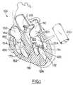
- Figure 1contains a cross-sectional cutaway depiction of a normal human heart 100 (shown next to heart 100 is a segment of tubular tissue 200 which will be used to replace the mitral valve, as described below).
- the left side of heart 100contains left atrium 110, left ventricular chamber 112 positioned between left ventricular wall 114 and septum 116, aortic valve 118, and mitral valve assembly 120.
- the components of the mitral valve assembly 120include the mitral valve annulus 121, which will remain as a roughly circular open ring after the leaflets of a diseased or damaged valve have been removed; anterior leaflet 122 (sometimes called the aortic leaflet, since it is adjacent to the aortic region); posterior leaflet 124; two papillary muscles 126 and 128 which are attached at their bases to the interior surface of the left ventricular wall 114; and multiple chordae tendineae 132, which couple the mitral valve leaflets 122 and 124 to the papillary muscles 126 and 128. There is no one-to-one chordal connection between the leaflets and the papillary muscles; instead, numerous chordae are present, and chordae from each papillary muscle 126 and 128 attach to both of the valve leaflets 122 and 124.
- the other side of the heartcontains the right atrium 150, a right ventricular chamber 152 bounded by right ventricular wall 154 and septum 116, and a tricuspid valve assembly 160.
- the tricuspid valve assembly 160comprises a valve annulus 162, three leaflets 164, papillary muscles 170 attached to the interior surface of the right ventricular wall 154, and multiple chordae tendineae 180 which couple the tricuspid valve leaflets 164 to the papillary muscles 170-174.
- the mitral valve leaflets 122 and 124, and tricuspid valve leaflets 164are all passive structures; they do not themselves expend any energy and do not perform any active contractile function. They are designed to simply open and close in response to differential pressures on either side of the leaflet tissue.
- the mitral valve 120opens (i.e., the leaflets 122 and 124 separate). Oxygenated blood flows in a downward direction through the valve 120, to fill the expanding ventricular cavity. Once the left ventricular cavity has filled, the left ventricle contracts, causing a rapid rise in the left ventricular cavitary pressure.
- the mitral valve 120This causes the mitral valve 120 to close (i.e., the leaflets 122 and 124 re-approximate) while the aortic valve 118 opens, allowing the oxygenated blood to be ejected from the left ventricle into the aorta.
- the chordae tendineae 132 of the mitral valveprevent the mitral leaflets 122 and 124 from prolapsing back into the left atrium 110 when the left ventricular chamber 114 contracts.
- the three leaflets, chordae tendineae, and papillary muscles of the tricuspid valvefunction in a similar manner, in response to the filling of the right ventricle and its subsequent contraction.
- the cusps of the aortic valvealso respond passively to pressure differentials between the left ventricle and the aorta.
- the aortic valvecusps open to allow the flow of oxygenated blood from the left ventricle into the aorta.
- the aortic valve cuspsreapproximate to prevent the blood which has entered the aorta from leaking (regurgitating) back into the left ventricle.
- the pulmonary valve cuspsrespond passively in the same manner in response to relaxation and contraction of the right ventricle in moving de-oxygenated blood into the pulmonary artery and thence to the lungs for re-oxygenation. Neither of these semilunar valves has associated chordae tendineae or papillary muscles.
- Heart valvesmay exhibit abnormal anatomy and function as a result of congenital or acquired valve disease.
- Congenital valve abnormalitiesmay be so severe that emergency surgery is required within the first few hours of life, or they may be well-tolerated for many years only to develop a life-threatening problem in an elderly patient.
- Acquired valve diseasemay result from causes such as rheumatic fever, degenerative disorders of the valve tissue, bacterial or fungal infections, and trauma.
- Heart valvesare passive structures that simply open and close in response to differential pressures on either side of the particular valve
- problems that can develop with valvescan be classified into two categories: 1) stenosis, in which a valve does not open properly, or 2) insufficiency (also called regurgitation), in which a valve does not close properly.
- stenosisin which a valve does not open properly
- insufficiencyalso called regurgitation
- Stenosis and insufficiencymay occur concomitantly in the same valve or in different valves. Both of these abnormalities increase the workload placed on the heart, and the severity of this increased stress on the heart and the patient, and the heart's ability to adapt to it, determine whether the abnormal valve will have to be surgically replaced (or, in some cases, repaired) or not.
- a particular type of prosthesisi.e., artificial valve
- available prosthesesinclude three categories of valves or materials: mechanical valves, tissue valves, and aortic homograft valves. These are briefly discussed below; they are illustrated and described in detail in texts such as Replacement Cardiac Valves, edited by E. Bodnar and R. Frater (Pergamon Press, New York, 1991).
- Mechanical valvesinclude caged-ball valves (such as Starr-Edwards valves), bi-leaflet valves (such as St. Jude valves), and tilting disk valves (such as Medtronic-Hall or Omniscience valves).
- Caged ball valvesusually are made with a ball made of a silicone rubber (SilasticTM) inside a titanium cage, while bileaflet and tilting disk valves are made of various combinations of pyrolytic carbon and titanium. All of these valves are attached to a cloth (usually DacronTM) sewing ring so that the valve prosthesis can be sutured to the patient's native tissue to hold the artificial valve in place postoperatively. All of these mechanical valves can be used to replace any of the heart's four valves. No other mechanical valves are currently approved for use by the FDA in the U.S.A.
- the main advantage of mechanical valvesis their long-term durability. Their main disadvantage is that they require the patient to take systemic anticoagulation drugs for the rest of his or her life, because of the propensity of mechanical valves to cause blood clots to form on them. If such blood clots form on the valve, they may preclude the valve from opening or closing correctly or, more importantly, the blood clots may disengage from the valve and embolize to the brain, causing a stroke.
- the anticoagulant drugs that are necessary to prevent thisare expensive and potentially dangerous in that they may cause abnormal bleeding which, in itself, can cause a stroke if the bleeding occurs within the brain.
- tissue valvesare constructed by sewing the leaflets of pig aortic valves to a stent (to hold the leaflets in proper position), or by constructing valve leaflets from the pericardial sac (which surrounds the heart) of cows or pigs and sewing them to a stent.
- the stentsmay be rigid or slightly flexible and are covered with cloth (usually a synthetic material sold under the trademark DacronTM) and attached to a sewing ring for fixation to the patient's native tissue.
- the porcine or bovine tissueis chemically treated to alleviate any antigenicity (i.e., to reduce the risk that the patient's body will reject the foreign tissue).
- These tri-leaflet valvesmay be used to replace any of the heart's four valves.
- the only tissue valves currently approved by the FDA for implantation in the U.S.A.are the Carpentier-Edwards Porcine Valve, the Hancock Porcine Valve, and the Carpentier-Edwards Pericardial Valve
- tissue valvesdo not cause blood clots to form as readily as do the mechanical valves, and therefore, they do not absolutely require systemic anticoagulation. Nevertheless, many surgeons do anticoagulate patients who have any type of artificial mitral valve, including tissue valves.
- tissue valveslack the long-term durability of mechanical valves. Tissue valves have a significant failure rate, usually appearing at approximately 8 years following implantation, although preliminary results with the new commercial pericardial valves suggest that they may last longer. One cause of these failures is believed to be the chemical treatment of the animal tissue that prevents it from being antigenic to the patient. In addition, the presence of the stent and sewing ring prevents the artificial tissue valve from being anatomically accurate in comparison to a normal heart valve, even in the aortic valve position.
- Homograft valvesare harvested from human cadavers. They are most commonly aortic valves but also occasionally include pulmonic valves. These valves are specially prepared and frozen in liquid nitrogen, where they are stored for later use in adults for aortic valve replacement, or in children for pulmonary valve replacement.
- a variant occasionally employed for aortic valve replacementis to use the patient's own pulmonary valve (an autograft) to replace a diseased aortic valve, combined with insertion of an aortic (or pulmonary) homograft from a cadaver to replace the excised pulmonary valve (this is commonly called a "Ross procedure").
- aortic homograft valvesappear to be as durable as mechanical valves and yet they do not promote blood clot formation and therefore, do not require anticoagulation.
- the main disadvantage of these valvesis that they are not available in sufficient numbers to satisfy the needs of patients who need new aortic or pulmonary valves. They also cannot be used to replace either the mitral valve or tricuspid valve. In addition, they are extremely expensive and much more difficult to implant than either mechanical or tissue valves.
- the difficulty in implantationmeans that the operative risk with a homograft valve is greater in a given patient than it is with either a mechanical or tissue valve.
- An additional problemis that in June 1992, the FDA re-classified homograft valves as an experimental device, so they are no longer available on a routine basis.
- All artificial heart valvesare designed to optimize three major physiologic characteristics and one practical consideration.
- the three major physiologic characteristicsare (1) hemodynamic performance, (2) thrombogenicity, and (3) durability.
- the practical considerationinvolves ease of surgical implantation.
- the Omniscience valvehas the partially opened disk itself in the valve orifice when open, and the Starr-Edwards caged-ball valve has both the ball and the cage within the flow orifice of the valve in the open position. All of these structures decrease the hemodynamic performance of the mechanical valves.
- the construction of artificial tissue valveshas been based on the concept that if the artificial valve can be made to approximate the anatomy (form) of the native valve, then the physiology (function) of the artificial valve will also approximate that of the native valve.
- Thisis the concept that " Function followss Form.”
- the manufacturers of all artificial porcine valvesfirst re-create the form of a native human aortic valve by: 1) harvesting a porcine aortic valve, 2) fixing it in glutaraldehyde to eliminate antigenicity, and 3) suturing the porcine valve to a stent to hold the three leaflets in place.
- the primary goal in the construction of these artificial valvesis to reproduce the form of the human aortic valve as closely as possible.
- the assumptionis made that if the artificial valve can be made to look like the human aortic valve, it will function like the human aortic valve (i.e., proper function will follow proper form).
- the same assumptionis also followed for commercially available pericardial valves.
- Porcine and bovine pericardial valvesnot only require chemical preparation (usually involving fixation with glutaraldehyde), but the leaflets must be sutured to cloth-covered stents in order to hold the leaflets in position for proper opening and closing of the valve.
- a recent advancehas been made in this regard by using "stentless" porcine valves that are sutured directly to the patient's native tissues for aortic valve replacement, but the problem of chemical fixation remains.
- these stentless artificial valvescannot be used for mitral or tricuspid valve replacement.
- the mitral valve disclosed by Mickleborough et alsuffers from a drawback which is believed to be important and perhaps even crucial to proper valve functioning.
- the anterior leafletdoes not have its center portion directly attached to the anterior papillary muscle via chordae. Instead, the anterior leaflet is attached to both the anterior and posterior papillary muscles, via chordae that are predominantly attached to the peripheral edges of the leaflet.
- a native posterior leafletis attached to both the anterior and posterior papillary muscles, via chordae that are predominantly attached to the peripheral edges of the leaflet.
- the line of commissure (closure) between the two mitral leaflets when the valve is closed during systoleis oriented in roughly the same direction as an imaginary line that crosses the tips of both papillary muscles.
- This orientation of the leaflets and papillary musclesis shown in illustrations such as page 11 of Netter 1969. This natural orientation can be achieved in the valve of the subject invention as depicted in FIGS. 2 and 3, discussed below.
- each sculpted leafletto be trimmed in a way that forms an extended flap, which becomes a relatively narrow strand of tissue near its tip.
- the tip of each pericardial tissue strandis sutured directly to a papillary muscle, causing the strand to mimic a chordae tendineae.
- Each strandextends from the center of a leaflet in the Mickleborough et al valve, and each strand is sutured directly to either an anterior and posterior papillary muscle. This requires each leaflet to be positioned directly over a papillary muscle.
- glutaraldehyde fixationas a treatment to reduce shrinkage or other physical distortion (as distinct from using it as a method of reducing tissue antigenicity) is an old and well-established technique for treating non-autologous tissue, but whether it is also beneficial for treating autologous tissue has not yet been extensively evaluated.
- the effects of chemical fixation of intestinal or other tubular tissue used to create heart valves as described hereincan be evaluated by routine experimentation.
- the subject inventionrelates to a method of using tubular starting material to replace any of the four heart valves during cardiac surgery. This approach is supported by and consistent with a fundamental principle of native heart valve function, which either went unrecognized in previous efforts to develop replacement valves, or which was sacrificed and lost when compromises were required to adapt available materials to surgical requirements.
- the entire cardiovascular systembegins in utero as a single, relatively straight tube of tissue.
- Anatomical drawings depicting the in utero development of the heartare available in numerous scientific publications and books, including Netter 1969.
- the so-called "heart tube”is readily discernible by the 23rd day of gestation. This tube will eventually develop into the entire cardiovascular system of the body.
- the tissue that exists between the portion of the tube destined to become the ventricles, and the portion that will become the atria,is where the mitral and tricuspid valves will ultimately form. This region of tissue is in a tubular form.
- the heart tubeundergoes a process of convolution beginning at approximately 25 days gestation. This convolution of the heart tube forms what is called the "heart loop" and is responsible for the aortic valve ultimately coming to lie adjacent to the mitral valve.
- the anterior portion of the mitral valve annulusis relatively flat. This distortion of the original roundness of the mitral annulus is caused by the presence of the aorta against the anterior mitral valve. It is also the reason that the anterior leaflet of the mitral valve is contiguous with the aortic valve annulus.
- the heart tube developmentreaches a stage that displays a first constricted tube region between the primordial right atrium and the primordial right ventricle (this portion of the tube will become the tricuspid valve) and a second constricted tube region between the primordial left atrium and primordial left ventricle (the future mitral valve).
- the tissues that are to eventually become the heart valvesmaintain their tubular structure.
- portions of the walls of these tubular structuresundergo a process of dissolution, leaving behind only those portions of the original tubes that are necessary for the proper functioning of the heart.
- This dissolutionalso affects the ventricular walls as they rapidly enlarge in size; if it did not, the walls would become prohibitively thick as the physical size of the heart increased, and the heart could not function effectively as a pump since it would become simply a large mass of ventricular muscle.
- the dissolution processalso operates on the tubular constrictions that will become the four heart valves.
- the necessary functional remnantsare the three cusps, which are the remains of the functioning portion of a simple tube. This principle is strengthened by the fact that although frequent reference is made to the pulmonic or aortic valve "annulus", knowledgeable anatomists are quick to point out that there is no such anatomical structure.
- the thickened tissue that is commonly referred to as the "annulus" of these valvesis simply the flexion point of the three cusps, the remnants of a simple tube that is fixed at three points distally and subjected to uniform pressure on its outside, resulting in collapse of the tube on the three sides between the points of distal fixation, which in turn, results in three nearly identical cusps. All tissue other than these moveable and functional cusps has undergone the normal process of dissolution as the aorta and pulmonary artery have enlarged, leaving behind only that tissue recognized as the cusps of these semilunar valves.
- valve leafletsare tube remnants, which are attached circumferentially to the fibrous annulus of the heart at their base and attached by chordae tendineae (additional tube remnants) at their free edges to papillary muscles (still more tube remnants) inside the ventricles.
- chordae tendineaeadditional tube remnants
- papillary muscles of each the two A-V valvesrepresent the necessary functional remnants of the original in utero tubular structures of the heart.
- the present inventionis based on the realization that a tubular structure having proper size and suitable material characteristics, if placed inside a mitral or tricuspid valve annulus after excision of the native valve (or inside an aorta or pulmonary artery, as described below) will function exactly like the normal valve in that position, assuming proper fixation of the inlet and outlet ends of the tube.
- the "Form Follows Function” principlepredicts that if the intended function of a replacement valve is to emulate the performance and function of a native mitral or tricuspid valve, then the form of a replacement valve--the structure and appearance of the replacement valve--should resemble the form of a native mitral or tricuspid valve. Since the native valves are generated from tubular starting material during fetal development, this principle further suggests that replacement valves should also be generated from tubular material.
- the artificial valvehad to be removed because its leaflets had become calcified and immobile, resulting in both mitral stenosis and mitral insufficiency.
- the surgeonwas struck by the similarity in shape and appearance of the diseased trileaflet valve to a normal mitral valve.
- the commissures of the three leaflet artificial tissue valvehad fused in a manner so that two leaflets had been formed: one large anterior leaflet, and one smaller posterior leaflet, as seen in a native mitral valve.
- the commissure between the two leaflets when the patent's valve was closed by back pressureclosely resembled the semi-circular commissure formed by leaflets in a native mitral valve.
- Form and function form a cycleThe following series can help to illustrate the principle, "Form and function form a cycle.”
- a formis created: tubular tissue is used to create a new mitral valve.
- This formthen creates a function: the new valve allows flow in only one direction, from the atrium to the ventricle.
- This functioncreates another form: the leaflets of the new mitral valve will close in a "smile" configuration resembling a native mitral valve during closure.
- This secondary formthen creates a secondary function: the new valve will provide good long-term use and low levels of turbulence, hemolysis, calcification, and leaflet stress.
- Form and function forma cycle, and this cycle cannot be disrupted by injecting and imposing an artificial, unnatural form in the heart without impeding the ability of proper form and proper function to interact with, support, and enhance each other.
- one object of this inventionis to provide a method of surgically replacing heart valves using natural autologous tubular tissue (i.e., the patient's own tissue) as the starting material.
- natural autologous tubular tissuei.e., the patient's own tissue
- Use of the patient's own tissuecan completely avoid the need for chemical processing, freezing, or other treatment, which are required to reduce the antigenicity of tissue obtained from animals or cadavers.
- Another object of this inventionis to provide a method of surgically replacing heart valves using innately tubular material (i.e., tissue or synthetic material which is harvested or synthesized in tubular form) as the starting material, to increase the long-term durability of replacement heart valves.
- innately tubular materiali.e., tissue or synthetic material which is harvested or synthesized in tubular form
- Another object of this inventionis to provide a method of using tubular starting material to create a replacement heart valve without requiring the use of a foreign object such as a stent to secure the replacement valve in position.
- Another object of this inventionis to provide a method of using tissue from a patient's own small intestine to create a replacement heart valve.
- Another object of this inventionis to provide replacement valves which are covered by a layer of epithelial cells, which do not create a risk of blood clot formation, thereby eliminating the need for a patient to take anti-coagulant drugs for the rest of his or her life.
- This inventioncomprises a method of using tubular material to replace a heart valve during cardiac surgery.
- the tube inletis sutured to the mitral or tricuspid valve annulus, and the outlet end of the tube is sutured to papillary muscles in the ventricle.
- the tube inletis sutured to the aortic or pulmonary valve annulus, and the tube is either "tacked" at three points distally, or sutured longitudinally along three lines; either method will allow the flaps of tissue between the suture lines to function as movable cusps.
- a preferred non-antigenic materialcomprises a segment of submucosal tissue from the small intestine of the same patient who is undergoing the cardiac operation.
- tissue from the same patientthe risk of immune rejection and the need to use fixation treatment to reduce the antigenicity of animal or cadaver tissue are eliminated.
- animal or human cadaver intestinal tissuecan be used if desired, if properly treated (such as by glutaraldehyde fixation) to reduce antigenicity, or biocompatible synthetic materials can be used.
- This inventionalso discloses a prepared, chemically treated intestinal tissue segment suitable for implantation as a replacement heart valve, with or without an annuloplasty ring attached to the tissue segment, enclosed in a sealed sterile package.
- This inventioncomprises a method of using tubular material to replace heart valves during cardiac surgery.
- a segment of small intestinal submucosal (SIS) tissueis used.
- the SIS tissuecan be harvested from the body of the same patient who is receiving the replacement valve. This eliminates the risk of immune rejection and the need to use fixation treatment to reduce the antigenicity of tissue from animals or cadavers.
- tubular starting materialrefers to material that is harvested from a human or animal body in tubular form (such as intestinal tissue), and to synthetic material that is synthesized, molded, woven, or otherwise created in tubular form.
- Tubular starting materialis distinct from flat starting material that has been secured by means such as suturing into a tubular intermediate form.
- a flexible tubular segmentwas created in a three-dimensional CAD-CAM program, which was run on a computer in the Applicant's research laboratory.
- the tube segmentwas affixed, at certain designated points, to the interior wall of a cylindrical flow conduit.
- One end (corresponding to the inlet) of the flow conduit and flexible tubewere flattened on one side, and the flexible tube inlet was fixed around the entire inner circumference of the flow conduit.
- the other end (the "outlet”) of the flexible tubewas fixed at only two opposed points inside the flow conduit.
- a similar CAD-CAM analysiswas performed for an aortic (or pulmonary) valve in which the inlet end of the flexible tube was fixed circumferentially around the inlet of the flow conduit, and the other end of the flexible tube was fixed at 3 equidistant points around the circumference of the conduit.
- the external pressure applied to the outside of the tubewas 80 mm Hg, corresponding to the arterial pressure exerted on normal aortic valve leaflets during diastole.
- the resultant shape of the tube after 12 hours of mathematical deformationappeared to exactly mimic a natural aortic valve.
- tubular starting materialsuch as intestinal tissue
- flat starting materialis advantageous, provided that the intestinal tissue segment has a diameter compatible with the valve being created.
- a pre-treated packaged segment of SIS tissue having the desired diameter from an animal (such as a pig) or a human cadavercan be used to avoid the need for using a longitudinal suture line to convert flat material into tubular material.
- This inventionteaches a method for replacing heart valves using tissue from the body of the same patient who receives the replacement valve.
- a segment of tissue several inches longis removed from the jejunal or ileal region of the small intestine.
- item 200 in Figure 1refers to a cylindrical (tubular) segment of tissue that has been surgically removed from the jejunal portion of the small intestine (i.e., the extended segment between the duodenal region near the stomach, and the ilial region).
- the jejunal region of the small intestineis approximately 6 meters (20 feet) long in an adult, and the removal of a short segment (such as about 15 cm, or 6 inches, which would provide more than enough SIS tissue to create a replacement valve) will not significantly affect the digestive capabilities of the patient.
- This segment of intestinal tissuecan be removed from the patient's abdomen during the same surgical operation used to replace the heart valve. Therefore, only one operation under general anesthesia is required, and the intestinal tissue is fresh and unaltered by storage and/or fixation when it is harvested for immediate use.
- the small intestine segments on each side of the removed portionare anastomosed (sutured together) using standard techniques, and the abdomen is closed. This entire abdominal portion of the operation can usually be performed in the time it takes to open the chest and cannulate the heart and great vessels in preparation for valve replacement.
- the intestinal segmentis wiped with a sterile cloth on the outside, to remove two outer layers of tissue known as the serosa and the muscularis (smooth muscle).
- the segmentis then turned inside out and wiped again to remove the mucosal layer that lines the inside of the intestinal segment.
- Tests using animalshave indicated that all three of these layers of the intestinal wall can be wiped off easily and without damaging the basement membrane or submucosa, by a simple wiping procedure. In tests on dogs, the wiping and cleaning procedure has taken only a few minutes.
- SISSmall Intestine Submucosa
- tissue if desiredcan also be used to treat the tissue if desired, such as glutaraldehyde or other crosslinking treatment.
- glutaraldehydeor other crosslinking treatment.
- Such treatmentis not necessary to reduce the antigenicity of the tissue, if the tissue comes from the same body that will be receiving the valve; however, as mentioned in the Background section, some reports suggest that treatment with a crosslinking agent such as glutaraldehyde can provide a useful degree of crosslinking between adjacent collagen fibers, which can reduce the tendency of certain types of tissue to shrink or thicken over prolonged periods of time.
- the SIS tissue segmentcan be implanted in a mitral valve position using any of several methods. In one method, it can be initially implanted as an unsculpted tube, then trimmed as necessary to preclude redundancy of the leaflets. This method can be performed as follows. The patient or animal is placed on total cardiopulmonary bypass so that the heart can be opened safely. The heart is either arrested or fibrillated and the mitral valve is exposed through an incision in the left atrium. The leaflets and chordae tendineae of the native mitral valve are surgically removed, leaving behind a mitral valve annulus 121. This annulus 121 has a roughly circular shape; however, as shown in FIG.
- annulus 2there is a somewhat “flattened” area 123 in the annulus, on the side closest to the aortic valve
- the base of the anterior leafletis attached to this "flattened” region of the mitral valve annulus.
- the inlet (proximal) 202 end of the tubular segment 200is sutured into the mitral valve annulus 121, using a suture line 204 which travels around the entire circumference of the annulus 121 and the tubular segment 200.
- an annuloplasty ring(such as illustrated in FIG. 8) can be used to create a bridge between the valve annulus 121 and the SIS tissue inlet 202.
- the length of the SIS segmentcan be trimmed to eliminate most of the excess length while retaining adequate tissue for the surgeon to work with.
- Suturesare then used to temporarily secure the outlet (distal) end of the tube to the papillary muscles at a distance from the mitral annulus compatible with the desired degree of "closure" of the tubular valve. This can be done by placing a tacking suture through the appropriate side of the tube distally and then passing it through the tip of the anterior papillary muscle 126. The same procedure is performed on the opposite side of the tube, temporarily attaching it to the posterior papillary muscle 128.
- Salineis then injected into the left ventricular chamber 112, which will remain capable of sustaining fluid pressure inside a closed chamber if access to the mitral valve is obtained via an incision through the left atrial wall.
- the saline flushgenerates fluid pressure in ventricle 112, which causes the sides of the tube to be forced into approximation. In other words, the saline flush closes the newly-created valve.
- the tube 200can permanently attached to the tips of the papillary muscles 126 and 128. This can be done in any of several ways. If the distal end of the SIS tissue has been carved, trimmed, or sculpted to create elongated wedges or strands of tissue which will serve as substitute chordae tendineae for attachment purposes, the distal ends of the sculpted tissue segments can be sutured to the papillary muscles.
- the tips of the tissue segmentscan be inserted into small incisions in the tips of the papillary muscles; these can then be reinforced using reinforcing devices on the outsides of papillary muscles, to reduce the risk of tearing the tissue segments or the tips of the papillary muscles.
- a sculpting or trimming stepwhich physically divides the replacement leaflets into an anterior leaflet that has been partially divided from the posterior leaflet is presumed to be preferable, because it can help the valve leaflets more closely emulate the physical shape of the leaflets in a native mitral valve. If such a sculpting or trimming step is desired, it can be carried out at any suitable time during the operation, such as immediately after a temporary suturing step followed by a saline flush have confirmed that a certain attachment configuration will function in the desired manner.
- the left atriumis closed and the heart is restarted.
- the leafletswill be forced open.
- this tubular valvewhen open during the systolic phase of each heartbeat, has no obstructions in its flow path.
- various devicesmust be positioned in the flow path of the blood. These hinder blood flow, leading to pressure gradients across the valve, especially at high flow rates and with small sized valves, and they also generate turbulence that can damage blood cells.
- previous artificial tissue valvesrequire stents and do not mimic the function of native valves, they also cause turbulence in blood flow, which is believed to be a potentially important factor in the production of calcification in the leaflets of the artificial tissue valve.
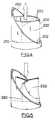
- FIG. 3shows a top view (from the left atrium) of the closed valve during contraction of the ventricle.
- the two sides of the tubeeffectively create a new anterior leaflet 122A and a new posterior leaflet 124A, which closely emulate the shapes and orientations of the native anterior leaflet 122 and the native posterior leaflet 124. Closure (approximation) of the replacement leaflets 122A and 124A against each other, caused by the pressure of the blood inside the ventricle, prevents backflow of blood (regurgitation) back into the left atrium.
- the commissure between the two natural leafletsis curved, in a manner that resembles a smile.
- the mitral valve annulus 121is not completely round, and has a "flattened" region 123 on the side closest to the aortic valve, and 2) pressure on the outside of any tube that has one flat side and is attached at two points distally (in line with the two ends of the flat side) will result in apposition of the two sides of that tube in a manner that resembles a smile.
- HOCMHypertrophic Obstructive Cardiomyopathy
- Tricuspid valve replacement in humansis especially problematic because tissue valves tend to fail earlier and mechanical valves tend to form clots at a much higher rate than either do in the mitral or aortic position.
- tissue valvestend to fail earlier and mechanical valves tend to form clots at a much higher rate than either do in the mitral or aortic position.
- re-infection of the new artificial valveis so common that some authors have actually advocated removal of an infected native valve without replacement with a new artificial one!
- the need for a satisfactory artificial valve for tricuspid valve replacementis especially acute.
- Tricuspid valve replacementcan be created in essentially the same manner as mitral valve replacement, described above.
- Preliminary studies on animalsindicate that the natural shape of the tricuspid annulus at the proximal end of a tube valve and three points of fixation distally to the normal papillary muscles in the right ventricle will result in an anatomically correct trileaflet tricuspid valve.
- papillary musclesare more variable and unpredictable in their placement than in the left ventricle; accordingly, tricuspid valves tend to be more difficult to replace than any of the other three valves, and successful replacement depends even more heavily upon the experience and expertise of the surgeon in tricuspid valve repair than in other valves.
- a preferred mode for surgical insertion of the valves described hereincompletely avoids the use of an annuloplasty ring.
- annuloplasty rings in the mitral or tricuspid positionpose a theoretical problem in regard to the threat of thrombosis. Accordingly, by disclosing replacement valves that can be created without using annuloplasty rings, this invention offers an advance over prior art replacement valves currently in use.
- annuloplasty ringsare widely used without severe adverse effects, and in many patients suffering from heart disease or congenital abnormalities, they can be advantageous or even necessary.
- this inventiondiscloses (1) replacement valves made of tubular tissue (or suitable synthetic material) coupled to annuloplasty rings, and (2) a method of surgically implanting such replacement valves.
- the tubular tissuewill work in the same manner as described above, while the annuloplasty ring will help create a bridge between the inlet end of the tubular tissue segment, and a valve annulus in a patient (such as a patient whose native mitral valve annulus is weak, dilated, and/or "rounded" out of its normal shape.
- the implantation of the annuloplasty ringcan be carried out using the same techniques that are currently used for mitral and tricuspid valve reparative techniques.
- the inlet rim of the SIS tissueis sutured to an annuloplasty ring.
- the annuloplasty ringhas been sutured to an atrioventricular valve annulus, the distal end of the SIS tissue is sutured to the papillary muscles as described above.
- the annuloplasty ringcan be coupled to the tube and both can be packaged together in a sealed package which maintains their sterility.
- This article of manufactureis described in more detail below and is shown in FIG. 8, in which a tubular segment 500 has been attached to an annuloplasty ring 502.
- the subject inventiondiscloses a method of using small intestinal submucosal (SIS) tissue in conjunction with an annuloplasty ring to create a heart valve replacement.
- SISsmall intestinal submucosal
- tubular valves of this inventiondo not require stents.
- the term "stent”includes any man-made device (other than a suture, annuloplasty ring, or leaflet material) which is surgically implanted in a patient's heart (or aorta or pulmonary artery) as part of a replacement valve, and which is contacted by blood which flows through the heart (or aorta or pulmonary artery). Stents are major components in all mechanical replacement valves, since they must securely hold the ball, flapper, or other movable elements of the valve in proper position; they are also used in nearly every type of artificial tissue valve, to secure the tissue flaps in the proper configuration.
- the term "stent”does not include reinforcing pledgets placed on the outside of an aorta or pulmonary artery, since such pledgets would not be contacted by blood flowing through the artery.
- Stentsare known to increase turbulence and thrombosis. Since the valves disclosed herein are stentless, this invention offers an important advance over prior art replacement valves which are currently approved by the FDA.
- atrioventricular (mitral or tricuspid) replacement valvecan be described as follows:
- a segment of intestinal tissue several inches longis removed from the patient and treated to remove the serosa, smooth muscle, and mucosal layers in the same manner described above.
- SISsmall intestinal submucosal
- the tubular materialmay be obtained from other animals or from human cadavers, or it may be manufactured from a suitable synthetic material.
- an SIS segmentis used.
- the desired lengthcan range from about 2 cm for neonates to about 6 cm for adults.
- an aortic wallis opened by an incision above the level of the commissural posts of the aortic valve, and the cusps of the native aortic valve are removed, leaving behind a valve annulus.
- the tubular SIS segment 200is then inserted, and as shown in FIGS. 4 and 5, the inlet end 202 is secured to the interior surface of the aortic wall 250 by means of a circumferential suture line 210; this step can utilize an annuloplasty ring if desired.
- the SIS segmentcan then be secured by means of three longitudinal suture lines 220 spaced at one-third intervals (120° apart from each other) around the internal periphery of the aortic wall 250.
- tissue segment 200Suturing the tissue segment 200 to the inside of the aortic (or pulmonary artery) wall 250 by means of three longitudinal suture lines 220 will leave three tissue regions 222 which will function as cusps during operation of the valve.
- tissue cylinder 220After the tissue cylinder 220 is properly secured and the patient's heart is closed by the surgeons and restarted, the three cusp regions 222 will go through a cyclical movement with each heartbeat.
- the cusps 222be held open by blood entering inlet end 202 and exiting outlet end 204.
- the three longitudinal suture lines 220can be reinforced by strips (often called pledgets) placed on the exterior of the aortic wall.
- These reinforcing stripscan be made of autologous tissue, materials sold under trademarks such as TEFLON, GORETEX, SILASTIC, or any other suitable material. Since these strips would be positioned outside the aorta or pulmonary artery, they would not come into contact with blood flowing through the artery. Therefore, they can reinforce the arterial wall, distribute any tensile stresses more evenly across a wider area of the arterial wall, and reduce the risk of tearing the arterial wall, without increasing the risk of thrombosis inside the artery. Depending on the positioning of the replacement valve in the aorta, it may also be desirable to place a similar strip around the exterior of an aorta or pulmonary artery to reinforce the circumferential inlet suture.
- reinforcing stripscan also be positioned inside an aorta or pulmonary artery, and a stent can be used to reinforce the inlet attachment.
- a stentcan be used to reinforce the inlet attachment.
- any reinforcing component which is exposed to blood inside the arterywould increase the risk of thrombosis and probably would suggest to the surgeon that the patient would need to be placed on anticoagulant drugs to reduce the risk of clot formation.
- the subject inventiondiscloses a method of replacing the aortic and pulmonary valves in which a round annuloplasty ring is used in conjunction with the artificial tubular tissue or mechanical valve. After obtaining a tubular segment of tissue or synthetic material, the tubular segment is sutured at its inlet end to a round annuloplasty ring which is then sutured into the aorta (or pulmonary artery) at the level of the lowest point of the excised native semilunar valve. The distal end of the tubular segment for both aortic valves and pulmonary valves is then handled in the same manner as described above for these valves without annuloplasty rings.
- non-planar cutssuch as a mildly sinusoidal cut
- non-planar outletscan be tested using any of several techniques (computerized CAD-CAM analysis, in vitro testing using a closed mechanical pumping circuit, or in vivo using animals such as dogs or sheep) to determine whether they are preferable to a square-end outlet, either for particular patients or as a general approach.
- a semilunar replacement valvei.e., an aortic or pulmonary valve
- the first methodinvolves creating a partial closure of adjacent cusps at their outer periphery. This can be done by gently pinching the walls of the inserted SIS cylinder 200 together at the outlet end of each of the three longitudinal suture lines 220 (or outlet attachment points), as shown in FIG. 6.
- the pinched SIS juncturescan then be held in place by one or more suture stitches 240.
- the suture stitches 240can be reinforced to prevent tearing of the SIS segment 200 by placing small reinforcing pieces 242, made of a flexible, soft, blood-compatible material such as GoreTex or Silastic, on the outside surfaces of the SIS wall 200, as shown in FIG. 6.
- An alternate potential method for ensuring that the three cusps will not become flattened against the inside of the aortainvolves a stent device that could be secured within the aortic wall 250, outside the SIS segment 200.
- This type of stentif used, would containing projections which extend in an inward radial direction, toward the central axis of the aorta. These projections, which would be positioned at midpoints between the three attachment points at the outlet end, would prevent any flattening of the cusp regions 222 against the interior of aortic wall 250. This would ensure that back pressure in the aorta would force each cusp in an inward direction, to ensure closure, rather than pressing the cusps in an outward direction which would cause them to flatten against the interior of the arterial wall and allow regurgitation.
- certain types of chemical treatment of intestinal or other tubular tissuemay be able to further reduce the calcification potential of a replacement valve that is created as described herein.
- autologous human intestinal tissuespecifically the submucosa of the small intestine (SIS)
- SISsmall intestine
- an important aspect of this inventionis the disclosure, in broad terms, that intestinal tissue harvested from the body of the same patient who is receiving a new heart valve can be used in the replacement valve.
- this inventiondiscloses a method of surgically replacing a heart valve in a human patient in need thereof, comprising the steps of (a) extracting a segment of intestinal tissue from the patient's abdomen, and (b) using the intestinal tissue to form at least one component of a replacement valve for the patient's heart. It also discloses certain articles of manufacture comprising previously prepared intestinal segments, from animals or human cadavers, which have been treated to render them suitable for use in creating replacement valves, and which are contained in sealed packages that maintain their sterility. These articles of manufacture are discussed in more detail below.
- autologous SIS intestinal tissuedescribed above appears to be an ideal tissue for creation of artificial tissue valves, the critical factor in the construction of such artificial tissue valves remains the tubular shape of the tissue or material to be implanted rather than the specific source of origin of that tissue or material.
- tissue from the body of the patient receiving the heart valve replacementcan be used if desired, rather than intestinal tissue.
- the pericardial sac which encloses the hearthas enough tissue so that a segment can be removed and used as a heart valve. This would allow a surgeon to conduct the entire operation without having to make an additional incision in the patient's abdomen.
- recent studies by othershave indicated the feasibility of using freshly harvested autologous pericardial tissue to create artificial cusps that can then be sutured inside the aorta to serve as an artificial aortic valve. That technique, however, differs in several ways from the current invention, and those investigators apparently have not recognized the importance of the principal that Form Follows Function.
- pericardial tissuewhich is essentially flat
- the subject inventionstates that pericardial tissue (which is essentially flat) can be used to replace an aortic valve if desired, but the pericardium should first be fashioned into a tube, and that tube should be fixed inside the aorta in the manner described above.
- Form follows FunctionBy fixing the inlet end of the tube circumferentially and the outlet end of the tube at 3 points (or along three longitudinal lines from the inlet), the external diastolic pressure in the aorta will cause the non-fixed sides of the tube to collapse against one another and the pericardial tube will be forced into the shape of a normal aortic valve.
- Form follows FunctionThe principle that Form follows Function will be operative in all artificial tubular valves used to replace any of the four native valves regardless of the specific type of tissue used to create the tubes.
- a potential source of tissueis the "fascia lata," a membranous layer which lies on the surface of certain skeletal muscles.
- Another potential source of autologous tissueis suggested by a known phenomenon involving mechanical objects that are implanted in the body, such as heart pacemakers. When such objects remain in the body for several months, they become encapsulated by a layer of smooth, rather homogeneous tissue. This phenomenon is described in articles such as Jansen et al 1989. The cellular growth process can also be controlled by manipulating the surface characteristics of the implanted device; see Chehroudi et al 1990. Based upon those observations and research, it is possible that mandrill implantation in the body of a patient who will need a heart valve replacement might become a potentially feasible technique for generating the cylindrical tissue.
- "homograft" tissuecan be harvested from the bodies of human cadavers for later use in artificial tubular heart valves.
- a very long segment of intestinal tissuecomprising all or a major portion of the jejunal region of the small intestine can be resected from the body of someone who has recently died, such as an accident victim. This harvesting operation would be comparable to harvesting a heart, kidney, or other internal organ from a deceased organ donor.
- the intestinal tissueis then cut into segments of roughly 10 to 20 cm (four to eight inches) each, which would then be prepared (by removing the serosa, smooth muscle, and submucosal layers), treated to reduce its antigenicity, and stored (at either refrigerated or frozen temperature) in a sterile preservation solution until use. When needed as a heart valve replacement, the tissue would be warmed and treated as necessary, and cut into the precise size and configuration needed.
- One advantage of this approachis that it would spare the cardiac patient from any additional pain or surgical stress that might result from having a surgical incision made in the abdomen to harvest autologous SIS tissue as described above.
- the additional stress or pain of obtaining a segment of intestinal tissue through a small abdominal incisionis quite small compared to open-heart surgery, where the chest and rib cage must be opened.
- several of the newest approaches to coronary artery bypass surgery(the most frequently performed cardiac operation) require much larger abdominal incisions to harvest abdominal arteries that are now used as bypass conduits.
- heterograft tissuefrom other animal species. This embodiment probably would require chemical fixation of the heterograft tissue (which presumably would comprise intestinal segments) by techniques such as glutaraldehyde crosslinking, as currently used to fix porcine or bovine pericardial tissue for conventional heart valve replacements.
- glutaraldehyde crosslinkingas currently used to fix porcine or bovine pericardial tissue for conventional heart valve replacements.
- intestine-derived tubular tissue fixed in glutaraldehydeto have problems similar to the presently available tissue valves, the calcification and durability problems of current tissue valves should be substantially reduced because of the tubular structure of the resultant valves, which would reproduce the function of the native valves, thereby leading to less turbulence and hence, less calcification, and greater long-term durability.
- intestinal tissuefor use herein include the following species: humans, non-human primates, and pigs (especially pigs descended from ancestors that were genetically engineering to have reduced tissue antigenicity; for the purpose of interpreting the claims, any pig which has descended from a genetically-engineered hypoallergenic pig is itself considered to be a genetically-engineered hypoallergenic pig, since the genetically-engineered hypoallergenic traits are inheritable).
- tubular synthetic materialAs a starting material for such valves, this invention also suggests the use of tubular synthetic material as a starting material for such valves.
- Various types of highly durable and flexible synthetic materialshave been developed and are continuing to be developed, and some of these materials are promising candidates which can be evaluated for possible use as described herein.
- One such materialis sold under the trademark "GoreTex.” It is, in essence, a polymerized layer of PTFE which is rendered flexible by coating it onto a flexible woven or knitted substrate material, such as nylon fabric. By coating PTFE onto a tubular substrate, it is possible to create tubular forms of such coated materials.
- Such materialsare highly durable inside the body, they can occasionally causes problems of blood clotting, apparently due in part to their rough surface textures, and possibly due also to plasticizers and other chemicals used to control the polymerization, thickness, and flexibility of the PTFE coating material.
- Perfluorinated elastomersa different class of synthetic materials that have recently been developed, also offer promise as potential artificial tubular valves as described herein. These elastomers are described in patents such as U.S. patent 4,900,793 (Lagow and Chester, 1990). Essentially, they contain only carbon and fluorine atoms, which are bonded together in highly stable polymeric configurations. Perfluorinated elastomers contain very little oxygen, hydrogen, nitrogen, sulfur, or other substances that might chemically react with physiological fluids to degrade the elastomer or cause leaching of constituent ions into the blood.
- elastomerscan provide very smooth surfaces, and since they are elastomeric in their own right, it is unnecessary to coat them onto the rough surface of a second material such as woven or knitted nylon in order to provide flexibility. They can be molded or otherwise synthesized directly into tubular form.
- an essentially tubular configurationcan be provided which has a gradually varying diameter.
- a relatively long tubular devicecan be created from synthetic material, having a diameter at the inlet end of up to about 5 cm and a diameter at the outlet end of about 2 cm.
- a surgeoncan simply cut the piece of tubing at any appropriate location along its length, to provide an inlet diameter corresponding to the diameter of a patient's valve annulus, which can be measured after the heart has been opened and the damaged or defective leaflets have been removed.
- a single tubing sizecan be adapted to accommodate various different patients; this will reduce the costs that would be required to manufacture or stock tubes having multiple different sizes.
- this inventiondiscloses an article of manufacture depicted in FIG. 7.
- This itemcomprises a tubular segment 500, made of tissue from the small intestine, or synthetic material having suitable overall dimensions and walls sufficiently thin and flexible to allow them to function as leaflets in a heart replacement valve. Since autologous tissue would not require storage for later use, this portion of the disclosure relates to the use of non-autologous (homograft or heterograft) tissue.
- This tubular segment 500is enclosed within a sealed container 510 that maintains sterility of the segment 500.
- a sterile container 510can comprise a plastic pouch, as shown in FIG. 7, having a transparent front layer 512 to allow visual inspection (this layer is shown folded up at one corner, for depiction purposes only). The front layer 512 is sealed around its periphery to a back layer 514.
- tubular segment 500is attached to an annuloplasty ring 502 before both are sealed inside package 510.
- the tube-to-ring attachmentcan be done by suturing in the case of tubular tissue segments, or by any suitable synthetic method (such as molding) if a synthetic tube is attached to a synthetic annuloplasty ring.
- intestinal tissueIf intestinal tissue is used, it should be packaged in hydrated form, in a suitable liquid (such as phosphate-buffered saline with one or more preservative agents, such as glutaraldehyde, if desired) contained within the pouch.
- a suitable liquidsuch as phosphate-buffered saline with one or more preservative agents, such as glutaraldehyde, if desired
- Such pouchescan be shipped and stored in stiff-walled boxes for protection; alternately, instead of using a flexible pouch as the container, a plastic box with a transparent closure layer sealed around its rim can be used as the container itself.
- a segment of intestinal tissueis contained in such a sterile container, it preferably should be treated before being sealed within the pouch, to remove the exterior serosa and muscularis layers and the interior mucosal layer, leaving only the desirable submucosal and basement layers.
- a synthetic tube as described hereincan have a diameter that varies gradually over its length. Such a tube can be transsected at a location having the desired diameter. This would allow a tube with a single size to accommodate patients who have valve annulus diameters with varying sizes.
- an SIS segmentcan be cut longitudinally, to convert it into a flat segment that can be trimmed to any desired size before creation of the replacement valve.
- three longitudinal suture linescan be used to create a replacement aortic or pulmonary valve, as part of the surgical procedure. Therefore, one of these suture lines can be used to re-size the SIS segment into a different diameter while retaining its tubular form.
- a prepackaged intestinal tissue segmentcan be used which has the desired diameter, harvested from a human cadaver or animal. This would avoid the need for a longitudinal cut, and it would preserve the tubular form of the intestinal segment throughout the entire procedure. Tissue from cadavers or animals would need to be treated by fixation (using glutaraldehyde crosslinking or another suitable method) to reduce its antigenicity before implantation.
- one of the preferred embodiments of this inventioncomprises an array of sealed sterile packages containing intestinal tissue segments from cadavers or animals for use in creating replacement valves.
- Each separate containerwould hold an intestinal segment having a known diameter or circumference (presumably measured in millimeters), which would be indicated on the label of the container.
- the tissue segmentsBefore being packaged, the tissue segments would be cleaned to remove the undesired tissue layers and fixed to reduce antigenicity.
- a surgeonopens a patient's chest and excises the cusps or leaflets from a diseased or damaged valve, he or she can directly measure the valve annulus. This measurement will indicate the exact diameter or circumference of the intestinal segment that should be used.
- a sealed package containing an intestinal tissue segment having the desired diameter or circumferencecan be selected and opened, and the segment will be immediately available. If desired, the tissue segment in the sterile package can already be attached to an annuloplasty ring, which would also be contained in the package.
- this inventiondiscloses an article of manufacture comprising a sealed sterile package containing a tubular intestinal tissue segment which has been treated to render it suitable for implantation as a heart valve.
- the diameter or circumference of the intestinal segmentpreferably should be indicated on the label of the package, and if desired, the intestinal tissue can be affixed at one end to an annuloplasty ring.
- these prepackaged intestinal segmentsthey can be sold and stored in groups of packages containing tissue segments having various sizes, so that a package containing an intestinal segment having an exact desired diameter or circumference will be available to a surgeon during a cardiac operation even if he cannot specify the exact size before the operation begins.
- An article of manufacturecomprising a sealed container and an enclosed intestinal tissue segment suitable for surgical implantation as a replacement valve in a mammalian heart, wherein:
- the sealed containeralso contains a suitable liquid which keeps the intestinal tissue segment in hydrated form.
- the sealed containerallows visual inspection of the tissue segment through at least one side of the container which comprises transparent plastic.
- the sealed containercomprises a label which indicates an average diameter of the intestinal tissue segment.
- tissue segmentis attached at one end to an annuloplasty ring.
- a method of surgically replacing an atrioventricular heart valve in a human patient in need thereofcomprising the following steps:
- the intestinal tissueis used to replace a mitral valve in a ventricular chamber having an anterior papillary muscle and a posterior papillary muscle
- the intestinal tissueis sutured to both papillary muscles in a manner which generates an anterior replacement leaflet and a posterior replacement leaflet, both of which span the distance between the anterior papillary muscle and the posterior papillary muscle, thereby causing the anterior replacement leaflet and the posterior replacement leaflet to form a line of commissure during valve closure which closely approaches the anterior papillary muscle tip and the posterior papillary muscle tip.
- the intestinal tissueis extracted from a mammalian animal other than the patient, wherein the animal is selected from the group consisting of humans, non-human primates, and genetically-engineered hypoallergenic pigs.
- a method of surgically creating an atrioventricular replacement valve in a patient's heartcomprising the following steps:
- tubular segmentconsists essentially of intestinal tissue.
- tubular segmentconsists essentially of synthetic material.
- atrioventricular replacement valveis created without utilizing a stent or annuloplasty ring, and wherein the tubular segment is sutured directly to the valve annulus.
- atrioventricular replacement valveis created by utilizing an annuloplasty ring to provide a bridge between the valve annulus and the inlet end of the tubular tissue segment.
- a method of surgically replacing a semilunar heart valve in a human patient in need thereofcomprising the following steps:
- a method of surgically creating a semilunar replacement valve in a heart of a patient in need thereofcomprising the following steps:
- tubular segmentconsists essentially of intestinal tissue.
- tubular segmentconsists essentially of synthetic material.
- atrioventricular replacement valveis created by utilizing an annuloplasty ring to provide a bridge between the valve annulus and the inlet end of the tubular tissue segment.
Landscapes
- Health & Medical Sciences (AREA)
- Life Sciences & Earth Sciences (AREA)
- Engineering & Computer Science (AREA)
- Biomedical Technology (AREA)
- Chemical & Material Sciences (AREA)
- Veterinary Medicine (AREA)
- Oral & Maxillofacial Surgery (AREA)
- Public Health (AREA)
- General Health & Medical Sciences (AREA)
- Animal Behavior & Ethology (AREA)
- Transplantation (AREA)
- Epidemiology (AREA)
- Medicinal Chemistry (AREA)
- Dermatology (AREA)
- Vascular Medicine (AREA)
- Chemical Kinetics & Catalysis (AREA)
- Botany (AREA)
- Molecular Biology (AREA)
- Cardiology (AREA)
- Urology & Nephrology (AREA)
- Zoology (AREA)
- Heart & Thoracic Surgery (AREA)
- Prostheses (AREA)
- Materials For Medical Uses (AREA)
- External Artificial Organs (AREA)
Abstract
Description
This invention is in the field of heart surgery and relatesto replacement of diseased or injured heart valves.
There are four valves in the heart that serve to direct theflow of blood through the two sides of the heart in a forwarddirection. On the left (systemic) side of the heart are: 1) themitral valve, located between the left atrium and the leftventricle, and 2) the aortic valve, located between the leftventricle and the aorta. These two valves direct oxygenatedblood coming from the lungs, through the left side of the heart,into the aorta for distribution to the body. On the right(pulmonary) side of the heart are: 1) the tricuspid valve,located between the right atrium and the right ventricle, and 2)the pulmonary valve, located between the right ventricle and thepulmonary artery. These two valves direct de-oxygenated bloodcoming from the body, through the right side of the heart, intothe pulmonary artery for distribution to the lungs, where itagain becomes re-oxygenated to begin the circuit anew.
All four of these heart valves arepassive structures inthat they do not themselves expend any energy and do not performany active contractile function. They consist of moveable"leaflets" that are designed simply to open and close inresponse to differential pressures on either side of the valve.The mitral and tricuspid valves are referred to as"atrioventricular valves" because of their being situatedbetween an atrium and ventricle on each side of the heart. Themitral valve has two leaflets and the tricuspid valve has three.The aortic and pulmonary valves are referred to as "semilunarvalves" because of the unique appearance of their leaflets,which are more aptly termed "cusps" and are shaped somewhat likea half-moon. The aortic and pulmonary valves each have threecusps.
Since the physiological structures of native mitral andtricuspid valves and native aortic and pulmonary valves areimportant to this invention, they are depicted in Figure 1,which contains a cross-sectional cutaway depiction of a normalhuman heart 100 (shown next toheart 100 is a segment oftubulartissue 200 which will be used to replace the mitral valve, asdescribed below). The left side ofheart 100 containsleftatrium 110, leftventricular chamber 112 positioned between leftventricular wall 114 andseptum 116,aortic valve 118, andmitral valve assembly 120. The components of themitral valveassembly 120 include themitral valve annulus 121, which willremain as a roughly circular open ring after the leaflets of adiseased or damaged valve have been removed; anterior leaflet122 (sometimes called the aortic leaflet, since it is adjacentto the aortic region);posterior leaflet 124; twopapillarymuscles ventricular wall 114; andmultiplechordae tendineae 132, which couple themitral valve leaflets papillary muscles papillary muscle valve leaflets
The other side of the heart contains theright atrium 150,a rightventricular chamber 152 bounded by rightventricularwall 154 andseptum 116, and atricuspid valve assembly 160. Thetricuspid valve assembly 160 comprises avalve annulus 162,threeleaflets 164,papillary muscles 170 attached to theinterior surface of the rightventricular wall 154, andmultiplechordae tendineae 180 which couple thetricuspid valve leaflets 164 to the papillary muscles 170-174.
As mentioned above, themitral valve leaflets tricuspid valve leaflets 164 are all passive structures;they do not themselves expend any energy and do not perform anyactive contractile function. They are designed to simply openand close in response to differential pressures on either sideof the leaflet tissue. When the leftventricular wall 114relaxes so that theventricular chamber 112 enlarges and drawsin blood, themitral valve 120 opens (i.e., theleaflets valve 120, to fill the expanding ventricular cavity.Once the left ventricular cavity has filled, the left ventriclecontracts, causing a rapid rise in the left ventricular cavitarypressure. This causes themitral valve 120 to close (i.e., theleaflets aortic valve 118opens, allowing the oxygenated blood to be ejected from the leftventricle into the aorta. Thechordae tendineae 132 of themitral valve prevent themitral leaflets left atrium 110 when the leftventricular chamber 114 contracts.
The three leaflets, chordae tendineae, and papillarymuscles of the tricuspid valve function in a similar manner, inresponse to the filling of the right ventricle and itssubsequent contraction.
The cusps of the aortic valve also respond passively topressure differentials between the left ventricle and the aorta.When the left ventricle contracts, the aortic valve cusps opento allow the flow of oxygenated blood from the left ventricleinto the aorta. When the left ventricle relaxes, the aorticvalve cusps reapproximate to prevent the blood which has enteredthe aorta from leaking (regurgitating) back into the leftventricle. The pulmonary valve cusps respond passively in thesame manner in response to relaxation and contraction of theright ventricle in moving de-oxygenated blood into the pulmonaryartery and thence to the lungs for re-oxygenation. Neither ofthese semilunar valves has associated chordae tendineae orpapillary muscles.
In summary, with relaxation and expansion of the ventricles(diastole), the mitral and tricuspid valves open, while theaortic and pulmonary valves close. When the ventricles contract(systole), the mitral and tricuspid valves close and the aorticand pulmonary valves open. In this manner, blood is propelledthrough both sides of the heart.
The anatomy of the heart and the structure and terminologyof heart valves are described and illustrated in detail innumerous reference works on anatomy and cardiac surgery,including standard texts such asSurgery of the Chest (Sabistonand Spencer, eds., Saunders Publ., Philadelphia) andCardiacSurgery by Kirklin and Barrett-Boyes.
Heart valves may exhibit abnormal anatomy and function as aresult of congenital or acquired valve disease. Congenital valveabnormalities may be so severe that emergency surgery isrequired within the first few hours of life, or they may bewell-tolerated for many years only to develop a life-threateningproblem in an elderly patient. Acquired valve disease may resultfrom causes such as rheumatic fever, degenerative disorders ofthe valve tissue, bacterial or fungal infections, and trauma.
Since heart valves are passive structures that simply openand close in response to differential pressures on either sideof the particular valve, the problems that can develop withvalves can be classified into two categories: 1) stenosis, inwhich a valve does not open properly, or 2) insufficiency (alsocalled regurgitation), in which a valve does not close properly.Stenosis and insufficiency may occur concomitantly in the samevalve or in different valves. Both of these abnormalitiesincrease the workload placed on the heart, and the severity ofthis increased stress on the heart and the patient, and theheart's ability to adapt to it, determine whether the abnormalvalve will have to be surgically replaced (or, in some cases,repaired) or not.
In addition to stenosis and insufficiency of heart valves,surgery may also be required for certain types of bacterial orfungal infections in which the valve may continue to functionnormally, but nevertheless harbors an overgrowth of bacteria (aso-called "vegetation") on the leaflets of the valve that mayflake off ("embolize") and lodge downstream in a vital artery.If such vegetations are on the valves of the left side (i.e.,the systemic circulation side) of the heart, embolizationresults in sudden loss of the blood supply to the affected bodyorgan and immediate malfunction of that organ. The organ mostcommonly affected by such embolization is the brain, in whichcase the patient suffers a stroke. Thus, surgical replacement ofeither the mitral or aortic valve (left-sided heart valves) maybe necessary for this problem even though neither stenosis norinsufficiency of either valve is present. Likewise, bacterial or fungal vegetations on the tricuspid valve may embolize to thelungs (resulting in a lung abscess) and therefore, may requirereplacement of the tricuspid valve even though no tricuspidvalve stenosis or insufficiency is present. With the exceptionof congenital pulmonary valve stenosis or insufficiency, it isunusual for a patient to develop an abnormality of the pulmonaryvalve that is significant enough to require surgical repair orreplacement.
Currently, surgical repair of mitral and tricuspid valvesis preferred over total valve replacement when possible,although often the valves are too diseased to repair and must bereplaced. Most abnormalities of the aortic valve requirereplacement, although some efforts are now being made to repairinsufficient aortic valves in selected patients. Valve repairand valve replacement surgery is described and illustrated innumerous books and articles, including the texts cited herein.
If a heart valve must be replaced, there are currentlyseveral options available, and the choice of a particular typeof prosthesis (i.e., artificial valve) depends on factors suchas the location of the valve, the age and other specifics of thepatient, and the surgeon's experiences and preferences.Available prostheses include three categories of valves ormaterials: mechanical valves, tissue valves, and aortichomograft valves. These are briefly discussed below; they areillustrated and described in detail in texts such asReplacementCardiac Valves, edited by E. Bodnar and R. Frater (PergamonPress, New York, 1991).
Mechanical valves includecaged-ball valves (such as Starr-Edwardsvalves),bi-leaflet valves (such as St. Jude valves),andtilting disk valves (such as Medtronic-Hall or Omnisciencevalves). Caged ball valves usually are made with a ball made ofa silicone rubber (Silastic™) inside a titanium cage, while bileafletand tilting disk valves are made of various combinationsof pyrolytic carbon and titanium. All of these valves areattached to a cloth (usually Dacron™) sewing ring so that the valve prosthesis can be sutured to the patient's native tissueto hold the artificial valve in place postoperatively. All ofthese mechanical valves can be used to replace any of theheart's four valves. No other mechanical valves are currentlyapproved for use by the FDA in the U.S.A.
The main advantage of mechanical valves is their long-termdurability. Their main disadvantage is that they require thepatient to take systemic anticoagulation drugs for the rest ofhis or her life, because of the propensity of mechanical valvesto cause blood clots to form on them. If such blood clots formon the valve, they may preclude the valve from opening orclosing correctly or, more importantly, the blood clots maydisengage from the valve and embolize to the brain, causing astroke. The anticoagulant drugs that are necessary to preventthis are expensive and potentially dangerous in that they maycause abnormal bleeding which, in itself, can cause a stroke ifthe bleeding occurs within the brain.
In addition to the mechanical valves available forimplantation today, a number of other valve designs aredescribed and illustrated in a chapter called "Extinct CardiacValve Prostheses," at pages 307-332 ofReplacement CardiacValves (Bodnar and Frater, cited above). Two of the "extinct"valves which deserve attention as prior art in the subjectinvention are the McGoon valve (pp. 319-320) and the Roe-Moorevalve (pp. 320-321). Both of these involve flexible leafletsmade of an elastomer or cloth coated withpolytetrafluoroethylene (PTFE, widely sold under the trademarkTEFLON), mounted inside a cylindrical stent. Although both weretested in humans, they were never commercialized and apparentlyare not being actively studied or developed today.
Most tissue valves are constructed by sewing the leafletsof pig aortic valves to a stent (to hold the leaflets in properposition), or by constructing valve leaflets from thepericardial sac (which surrounds the heart) of cows or pigs andsewing them to a stent. The stents may be rigid or slightlyflexible and are covered with cloth (usually a syntheticmaterial sold under the trademark Dacron™) and attached to a sewing ring for fixation to the patient's native tissue. Theporcine or bovine tissue is chemically treated to alleviate anyantigenicity (i.e., to reduce the risk that the patient's bodywill reject the foreign tissue). These tri-leaflet valves may beused to replace any of the heart's four valves. The only tissuevalves currently approved by the FDA for implantation in theU.S.A. are the Carpentier-Edwards Porcine Valve, the HancockPorcine Valve, and the Carpentier-Edwards Pericardial Valve.
The main advantage of tissue valves is that they do notcause blood clots to form as readily as do the mechanicalvalves, and therefore, they do not absolutely require systemicanticoagulation. Nevertheless, many surgeons do anticoagulatepatients who haveany type of artificial mitral valve, includingtissue valves. The major disadvantage of tissue valves is thatthey lack the long-term durability of mechanical valves. Tissuevalves have a significant failure rate, usually appearing atapproximately 8 years following implantation, althoughpreliminary results with the new commercial pericardial valvessuggest that they may last longer. One cause of these failuresis believed to be the chemical treatment of the animal tissuethat prevents it from being antigenic to the patient. Inaddition, the presence of the stent and sewing ring prevents theartificial tissue valve from being anatomically accurate incomparison to a normal heart valve, even in the aortic valveposition.
Homograft valves are harvested from human cadavers. Theyare most commonly aortic valves but also occasionally includepulmonic valves. These valves are specially prepared and frozenin liquid nitrogen, where they are stored for later use inadults for aortic valve replacement, or in children forpulmonary valve replacement. A variant occasionally employed foraortic valve replacement is to use the patient's own pulmonaryvalve (an autograft) to replace a diseased aortic valve,combined with insertion of an aortic (or pulmonary) homograftfrom a cadaver to replace the excised pulmonary valve (this iscommonly called a "Ross procedure").
The advantage of aortic homograft valves is that they appear to be as durable as mechanical valves and yet they do notpromote blood clot formation and therefore, do not requireanticoagulation. The main disadvantage of these valves is thatthey are not available in sufficient numbers to satisfy theneeds of patients who need new aortic or pulmonary valves. Theyalsocannot be used to replace either the mitral valve ortricuspid valve. In addition, they are extremely expensive andmuch more difficult to implant than either mechanical or tissuevalves. The difficulty in implantation means that the operativerisk with a homograft valve is greater in a given patient thanit is with either a mechanical or tissue valve. An additionalproblem is that in June 1992, the FDA re-classified homograftvalves as an experimental device, so they are no longeravailable on a routine basis.
All artificial heart valves are designed to optimize threemajor physiologic characteristics and one practicalconsideration. The three major physiologic characteristics are(1) hemodynamic performance, (2) thrombogenicity, and (3)durability. The practical consideration involves ease ofsurgical implantation.
Multiple factors impact on each of these potential problemsin the development of artificial valves. As a result, theadvantage of artificial valve A over artificial valve B in onearea is typically counterbalanced by valve B's advantage inanother area. If one artificial heart valve were clearlysuperior in all aspects to all other artificial valves in allfour of these areas, it would be the only artificial valve used.
Thehemodynamic performance of mechanical heart valves hasbeen satisfactory but not optimal, especially in the smallersizes. All previously constructed mechanical heart valves havehad some type of obstructing structure within the flow orificeof the valve when the valve is in the open position. Forexample, bi-leaflet valves, such as the St. Jude valve, have twobars across the orifice and in addition, the leaflets themselvesare within the orifice when the valve is in the open position. Single-leaflet disc valves, such as the Medtronic-Hall valve,have a central bar and strut mechanism that keep the leaflet inplace. The Bjork-Shiley valves have either one or two strutsthat span the valve orifice in addition to the partially-openeddisc itself. The Omniscience valve has the partially opened diskitself in the valve orifice when open, and the Starr-Edwardscaged-ball valve has both the ball and the cage within the floworifice of the valve in the open position. All of thesestructures decrease the hemodynamic performance of themechanical valves.
Such obstructions also interfere with the normal flowpatterns within and around the mechanical valve and therefore,promote thrombosis. More importantly, all artificial surfacesarethromboqenic (clot-promoting) to a greater or lesser degree.The only completely non-thrombogenic (non-clot-promoting)surface that exists is the layer of viable endothelial cellsthat line the interior of all the body's vascular surfaces,including the inside of the heart chambers and the native valveleaflets. Therefore, any metal or plastic material, no matterhow highly polished, will have some level of thrombogenicityunless the surface of the artificial material can be coveredwith endothelial cells. It is for this reason that all patientswith artificial mechanical heart valves must be permanentlyanticoagulated.
The major advantage of mechanical valves over tissue valvesislong-term durability. Mechanical valve construction has beenbased on sophisticated engineering principles that have provento be sound in terms of providing devices that are extremelyresistant to wear and structural failure. Nevertheless,structural failure of mechanical valves does occur and it is themajor reason for the recent withdrawal from the market of twocommercially available mechanical valves (the Bjork-ShileyConcavo-Convex™ single disc valve and the Duramedics™ bileafletvalve).
Under the best of circumstances (i.e., replacement of theaortic valve), the construction of artificialtissue valves hasbeen based on the concept that if the artificial valve can be made to approximate the anatomy (form) of the native valve, thenthe physiology (function) of the artificial valve will alsoapproximate that of the native valve. This is the concept that"Function Follows Form." For example, the manufacturers of allartificial porcine valves first re-create theform of a nativehuman aortic valve by: 1) harvesting a porcine aortic valve, 2)fixing it in glutaraldehyde to eliminate antigenicity, and 3)suturing the porcine valve to a stent to hold the three leafletsin place. In other words, the primary goal in the constructionof these artificial valves is to reproduce theform of the humanaortic valve as closely as possible. The assumption is made thatif the artificial valve can be made tolook like the humanaortic valve, it willfunction like the human aortic valve(i.e., proper function will follow proper form). The sameassumption is also followed for commercially availablepericardial valves.
In the case of mitral or tricuspid valve replacement, eventhe dubious concept of "function follows form" has beendiscarded since the same artificial valves that are designed tolook like the aortic valve are used to replace the mitral andtricuspid valves. In other words, no attempt at all is made toreproduce even theform of these native valves, much less sotheirfunction.
Thus, in the case of artificial valves to be used foraortic valve replacement, the dubious concept of "functionfollows form" has dictated the construction of all artificialtissue valves during the 30 years of their development and use.Even worse, no discernable underlying concept at all has beenused in terms of the artificial valves used to replace themitral and tricuspid valves.
The "Function Follows Form" concept has several limitationsand appears to be a fundamental shortcoming which underlies thepresent construction of all artificial tissue valves. In thefirst place, it simply is not possible to re-create the exactanatomy (form) of a native heart valve utilizing presenttechniques. Although homograft (human cadaver) and porcineaortic valves have the gross appearance of native aortic valves,the fixation process (freezing with liquid nitrogen, andchemical treatment, respectively) alters the histologic (microscopic) characteristics of the valve tissue. Porcine andbovine pericardial valves not only require chemical preparation(usually involving fixation with glutaraldehyde), but theleaflets must be sutured to cloth-covered stents in order tohold the leaflets in position for proper opening and closing ofthe valve. A recent advance has been made in this regard byusing "stentless" porcine valves that are sutured directly tothe patient's native tissues for aortic valve replacement, butthe problem of chemical fixation remains. In addition, thesestentless artificial valves cannot be used for mitral ortricuspid valve replacement.
Perhaps the major limitation of the "Function Follows Form"concept is that no efforts have been made previously toapproximate the form of either the mitral valve or the tricuspidvalve. If animal tissue valves are used to replace either ofthese native valves, the tri-leaflet porcine aortic valveprosthesis or the tri-leaflet bovine pericardial valveprosthesis is normally used. In doing so, even the faultyconcept of "Function Follows Form" is ignored, since there areno artificial valves available for human use that approximatethe anatomy (form) of the native mitral or tricuspid valves.
The nearest attempt at reproducing the function of thenative mitral valve was reported by Mickleborough et al in 1989.These tests involved the use of commercially-prepared sheets ofpericardial tissue from cows, which had been treated withglutaraldehyde before storage and shipping. A longitudinalsuture line was used to convert the flat sheet of tissue into acylinder, then two triangular regions were removed from one endof the cylinder, to generate two flaps. The inlet end wassutured to the mitral valve annulus, while the two tissue flapsat the carved outlet end were sutured to the papillary muscles.
The mitral valve disclosed by Mickleborough et al suffersfrom a drawback which is believed to be important and perhapseven crucial to proper valve functioning. In a properlyfunctioning natural valve, the anterior leaflet does not haveits center portion directly attached to the anterior papillarymuscle via chordae. Instead, the anterior leaflet is attached toboth the anterior and posterior papillary muscles, via chordaethat are predominantly attached to the peripheral edges of the leaflet. In the same manner, a native posterior leaflet isattached to both the anterior and posterior papillary muscles,via chordae that are predominantly attached to the peripheraledges of the leaflet. As a result, the line of commissure(closure) between the two mitral leaflets when the valve isclosed during systole is oriented in roughly the same directionas an imaginary line that crosses the tips of both papillarymuscles. This orientation of the leaflets and papillary musclesis shown in illustrations such as page 11 of Netter 1969. Thisnatural orientation can be achieved in the valve of the subjectinvention as depicted in FIGS. 2 and 3, discussed below.
By contrast, the replacement valve described byMickleborough et al alters and distorts the proper orientationof the replacement leaflets. Mickleborough's approach requireseach sculpted leaflet to be trimmed in a way that forms anextended flap, which becomes a relatively narrow strand oftissue near its tip. The tip of each pericardial tissue strandis sutured directly to a papillary muscle, causing the strand tomimic a chordae tendineae. Each strand extends from the centerof a leaflet in the Mickleborough et al valve, and each strandis sutured directly to either an anterior and posteriorpapillary muscle. This requires each leaflet to be positioneddirectly over a papillary muscle. This effectively rotates theleaflets of the Mickleborough valve about 90° compared to theleaflets of a native valve. The line of commissure between theleaflets, when they are pressed together during systole, willbisect (at a perpendicular angle) an imaginary line that crossesthe peaks of the two papillary muscles, instead of lying roughlyalong that line as occurs in a native valve.
There has been no indication since the publication ofMickleborough et al 1989 that their approach is still beingstudied (either by them, or by any other research team), andthere has been no other indication during the intervening yearsthat their approach is likely to lead to a valve replacementtechnique for actual use in humans.
It should be noted that one of the primary goals ofMickleborough and her associates apparently was to propose a newway to maintain continuity between the valve annulus and thepapillary muscles. It was first proposed about 30 years ago (by C. W. Lillehei and perhaps by others as well) that proper muscletone of the left ventricular wall, and proper postoperativeventricular functioning, required a tension-bearing connectionbetween the mitral valve annulus and the papillary muscles onthe inside of the ventricular wall. This suggestion was widelyignored in the design of replacement mitral valves, whichrequired excision of the chordae tendineae without making anyeffort to provide a substitute that would keep the ventricularwall coupled to the valve annulus. However, various studies(such as Rittenhouse et al 1978, David 1986, Hansen et al 1987,and Miki et al 1988) continued to indicate that the tension-conveyingrole of the chordae was important to properventricular function. Based on those studies, Mickleborough etal apparently were attempting to create and propose a new valvedesign that could accomplish that goal. They did indeedaccomplish that goal, and the apparent lack of any follow-up orcommercialization of their design presumably was due to otherproblems, such as the altered orientation of the leaflets intheir design.
A different approach to creating artificial tissue valvesis described in articles such as Love and Love 1991, and in USpatents 5,163,955 (Calvin et al 1992) and 4,470,157 (Love 1984).In that research, surgeons harvested a piece of pericardialtissue from the same animal that was to receive the artificialvalve. Such tissue, if harvested from the same human body thatwill receive the implant, is referred to as autologous orautogenous (the terms are used interchangeably, by differentresearchers). Using a cutting die, the pericardial tissue wascut into a carefully defined geometric shape, treated withglutaraldehyde, then clamped in a sandwich-fashion between twostent components. This created a tri-leaflet valve that againresembles an aortic or pulmonary valve, having semilunar-typecusps rather than atrioventricular-type leaflets. These valveswere then tested in the mitral (or occasionally tricuspid) valveposition, using sheep.
Although those valves were structurally very different fromthe valves of the subject invention, the Love and Love articleis worth attention because it discusses chemical fixation. Theyused glutaraldehyde treatment even though their tissue source was from the same animal and was therefore non-antigenic,because earlier reports and tests had suggested that some typesof untreated autologous tissue suffer from thickening and/orshrinkage over time. Love and Love suggested that glutaraldehydecan help such tissue resist such changes, apparently by formingcrosslinking bonds that tend to hold adjacent collagen fibers ina fixed-but-flexible conformation. This use of glutaraldehydefixation as a treatment to reduce shrinkage or other physicaldistortion (as distinct from using it as a method of reducingtissue antigenicity) is an old and well-established techniquefor treating non-autologous tissue, but whether it is alsobeneficial for treating autologous tissue has not yet beenextensively evaluated. The effects of chemical fixation ofintestinal or other tubular tissue used to create heart valvesas described herein can be evaluated by routine experimentation.
Another report describing the use of autologous tissue toreconstruct mitral valves is Bailey et al 1970. However, Baileyet al focused on repairing rather than replacing mitral valves,usually by cutting an incision into one or both leaflets andthen inserting a segment of tissue into the incision to enlargethe leaflet(s).
The subject invention relates to a method of using tubularstarting material to replace any of the four heart valves duringcardiac surgery. This approach is supported by and consistentwith a fundamental principle of native heart valve function,which either went unrecognized in previous efforts to developreplacement valves, or which was sacrificed and lost whencompromises were required to adapt available materials tosurgical requirements.
The basic principle, which deserves repeated emphasisbecause it has been so widely disregarded by other efforts inthis field, is thatForm Follows Function. In one manifestationof this principle. if an artificial valve can be created thatcan trulyfunction like a native valve, its resultantform willbe similar to that of the native valve.
A highly important observation by the Applicant thatcontributed to the recognition of the pervasive and overriding importance of this principle was the following: the entirecardiovascular system, including the heart, beginsin utero as asingle, relatively straighttube of tissue. Anatomical drawingsdepicting thein utero development of the heart are available innumerous scientific publications and books, including Netter1969. As shown in those figures (or similar figures available inother medical reference works), the so-called "heart tube" isreadily discernible by the 23rd day of gestation. This tube willeventually develop into the entire cardiovascular system of thebody. The tissue that exists between the portion of the tubedestined to become the ventricles, and the portion that willbecome the atria, is where the mitral and tricuspid valves willultimately form. This region of tissue is in a tubular form.
The heart tube undergoes a process of convolution beginningat approximately 25 days gestation. This convolution of theheart tube forms what is called the "heart loop" and isresponsible for the aortic valve ultimately coming to lieadjacent to the mitral valve. When a mature mitral valve isviewed from the atrial side, the anterior portion of the mitralvalve annulus is relatively flat. This distortion of theoriginal roundness of the mitral annulus is caused by thepresence of the aorta against the anterior mitral valve. It isalso the reason that the anterior leaflet of the mitral valve iscontiguous with the aortic valve annulus. Finally, it explainswhy accessory atrioventricular connections (accessory pathways)that occur in the Wolff-Parkinson-White syndrome never occur inthis portion of the mitral valve annulus; this is the onlyportion of the entire atrioventricular groove on either side ofthe heart where the atrium and ventricle were never contiguousduring fetal development.
By approximately 56 days gestation, the heart tubedevelopment reaches a stage that displays a first constrictedtube region between the primordial right atrium and theprimordial right ventricle (this portion of the tube will becomethe tricuspid valve) and a second constricted tube regionbetween the primordial left atrium and primordial left ventricle(the future mitral valve).
As the developing heart of a fetus undergoes variousconvolutions, septations, and compartmentalizations, the tissues that are to eventually become the heart valves maintain theirtubular structure. Prior to the onset of fetal heart function,portions of the walls of these tubular structures undergo aprocess of dissolution,leaving behind only those portions ofthe original tubes that are necessary for the proper functioningof the heart. This dissolution also affects the ventricularwalls as they rapidly enlarge in size; if it did not, the wallswould become prohibitively thick as the physical size of theheart increased, and the heart could not function effectively asa pump since it would become simply a large mass of ventricularmuscle.
The dissolution process also operates on the tubularconstrictions that will become the four heart valves. In thecase of the semilunar valves (the aortic and pulmonary valves),the necessary functional remnants are the three cusps, which arethe remains of the functioning portion of a simple tube. Thisprinciple is strengthened by the fact that although frequentreference is made to the pulmonic or aortic valve "annulus",knowledgeable anatomists are quick to point out that there is nosuch anatomical structure. The thickened tissue that is commonlyreferred to as the "annulus" of these valves is simply theflexion point of the three cusps, the remnants of a simple tubethat is fixed at three points distally and subjected to uniformpressure on its outside, resulting in collapse of the tube onthe three sides between the points of distal fixation, which inturn, results in three nearly identical cusps. All tissue otherthan these moveable and functional cusps has undergone thenormal process of dissolution as the aorta and pulmonary arteryhave enlarged, leaving behind only that tissue recognized as thecusps of these semilunar valves.
At the mitral and tricuspid valves locations, thedissolution process leaves behind the valve leaflets, chordaetendineae, and papillary muscles in both the right ventricle(tricuspid valve) and left ventricle (mitral valve). In otherwords, that portion of the original tube that is necessary forthe development of the native heart valves is spared thedissolution process and the rest of the tube dissolves away. Thevalve leaflets are tube remnants, which are attachedcircumferentially to the fibrous annulus of the heart at their base and attached by chordae tendineae (additional tuberemnants) at their free edges to papillary muscles (still moretube remnants) inside the ventricles. The leaflets, chordaetendineae, and papillary muscles of each the two A-V valvesrepresent thenecessary functional remnants of the originalinutero tubular structures of the heart.
Using "Form Follows Function" as a basic guiding principle,the present invention is based on the realization that a tubularstructure having proper size and suitable materialcharacteristics, if placed inside a mitral or tricuspid valveannulus after excision of the native valve (or inside an aortaor pulmonary artery, as described below) willfunction exactlylike the normal valve in that position, assuming proper fixationof the inlet and outlet ends of the tube. The "Form FollowsFunction" principle predicts that if the intended function of areplacement valve is to emulate the performance and function ofa native mitral or tricuspid valve, then theform of areplacement valve--thestructure and appearance of thereplacement valve--should resemble the form of a native mitralor tricuspid valve. Since the native valves are generated fromtubular starting material during fetal development, thisprinciple further suggests that replacement valves should alsobe generated from tubular material.
This principle is given added support by the results thatwere observed in an artificial tissue valve that had beenimplanted into the mitral valve position in a human heart. TheApplicant learned of these results during a presentation byProfessor Donald Ross of the National Heart Hospital andBrompton Hospital (London, England), the cardiac surgeon who hadperformed that surgery. The implanted valve was originally acommercially availabletrileaflet tissue valve that wasimplanted into the mitral position in a 35-year-old female. Thetrileaflet valve had been constructed usingfascia lata tissue(a relatively tough and flexible layer of tissue that normallysurrounds certain types of muscles) which had been sewn into acircular stent. After 5 years, the artificial valve had to beremoved because its leaflets had become calcified and immobile,resulting in both mitral stenosis and mitral insufficiency. Uponexposing the artificial valve during the removal surgery, the surgeon was struck by the similarity in shape and appearance ofthe diseased trileaflet valve to a normal mitral valve. Thecommissures of thethree leaflet artificial tissue valve hadfused in a manner so thattwo leaflets had been formed: onelarge anterior leaflet, and one smaller posterior leaflet, asseen in a native mitral valve. Furthermore, the commissurebetween the two leaflets when the patent's valve was closed byback pressure closely resembled the semi-circular commissureformed by leaflets in a native mitral valve.
During the presentation by Professor Ross, the Applicantwitnessed a picture showing how the three-leaflet artificialvalve had been converted into a bi-leaflet valve during thecourse of five years inside a human heart. It became clear tothe Applicant that the patient's heart had been attempting tomake the valve conform to the heart's functional needs.
Prior to witnessing that presentation, the Applicant hadalready been considering the question of whether tubular tissuemight be useful for creating replacement heart valves. Afterseeing Prof. Ross's photographs, which provided strongphysiological confirmation of the "Form Follows Function"principle, the Applicant began to carry out experiments toassess the possibility of using tubular tissue to replace heartvalves. In a simple mechanical test, he obtained some highlyflexible rubber tubes by cutting off the fingers of surgicalgloves, then he sculpted the finger tubes to resemble theleaflets of mitral or tricuspid valves, then he sutured thesculpted rubber tubes inside of slightly larger tubes made ofDacron™. An internal rubber tube was secured proximally aroundthe entire periphery of a tube, to emulate a valve annulus, andthe sculpted rubber flaps at the distal ends were coupled to thetube walls by means of loose suture strands that emulatedchordae tendineae. When cyclical pressure was generated byattempting to blow and then suck air through the tube, theinterior rubber leaflets opened and closed in a manner thatlooked identical to natural mitral or tricuspid leaflets openingand closing. This provided additional confirmation of the "FormFollows Function" principle.
The physiologic principle that the functional components ofnative heart valves are the remnants of simple tissue tubes, and the idea of using tubular structures to replace defective heartvalves, has been completely ignored in the design andconstruction of all replacement valves in use today. Indeed,although "Form Follows Function" is a well-respected principlein fields such as engineering or evolutionary studies, it isoften disregarded among medical researchers, some of whomapparently seem to feel that efforts to sever or reverse thisrelationship represent triumphs of technology over nature. As anexample, kidney dialysis machines, which look nothing likenormal kidneys, are a purely technological, non-naturalsolution; they use a completely artificial form to generate andprovide a certain needed function. However, as any dialysispatient would attest, they fall far short of being trulyoptimal.
In a similar manner, all artificial heart valves in usetoday, whether tissue or mechanical, have been designed based onthe belief that either: 1) function can be forced to follow form(aortic and pulmonary valve replacement), or 2) neither functionnor form of the native valve can be reproduced, so a replacementvalve (either tissue or mechanical) must merely function as aone-way passive valve (mitral and tricuspid valve replacement).In the case of artificialtissue valves, theform of anartificial valve is established first, in the hope that thevalve willfunction in a manner similar to a native valve. Inthe case of artificialmechanical valves, the disruption of theinteraction between form and function goes even farther, and thecaged balls, hinged flappers, and other devices in mechanicalvalves have even less physical similarity to native valves.However, the problems in both of these approaches are evident inthe limitations suffered by every type of replacement valve thatis in use today.
There is another way to express the concept of "FormFollows Function" which may help explain it to people who wouldpoint to mechanical heart valves, dialysis machines, and othernon-natural forms that have been used to mimic the function ofbody parts. In such examples, function is forced to follow form.In crude and simple terms, the function of a heart valve ismerely to allow flow in one direction only. Any type ofmechanical check valve with a caged-ball or flapper-and-seat design can provide that level of function.
However, when the long-term aspects of heart valve functionare also taken into account (including the functions ofproviding low hemolysis, low turbulence, avoiding calcification,etc.), it becomes clear that artificial forms cannot fullyprovide those functions. The best and perhaps only way toprovide a replacement valve with the complete, long-termfunctionality of a natural heart valve is by giving properdeference to the relationship between function and form.
This principle can be stated as, "Form and function form acycle." Each follows the other, but each also precedes andaffects the other. If either half of this cycle is violated ordisrupted, it will create problems that will stand in the way ofan optimally functional, reliable, durable system with minimalhemolysis, turbulence, and calcification. On a short-term basis,function can be forced to adapt to an unnatural form; however,any such short-term solution will be plagued by problems andlimitations over the long run. The problems and shortcomings ofcurrent mechanical replacement valves are a clear and directdemonstration of this principle.
The following series can help to illustrate the principle,"Form and function form a cycle." First, a form is created:tubular tissue is used to create a new mitral valve. This formthen creates a function: the new valve allows flow in only onedirection, from the atrium to the ventricle. This function, inturn, creates another form: the leaflets of the new mitral valvewill close in a "smile" configuration resembling a native mitralvalve during closure. This secondary form then creates asecondary function: the new valve will provide good long-termuse and low levels of turbulence, hemolysis, calcification, andleaflet stress. Form and function form a cycle, and this cyclecannot be disrupted by injecting and imposing an artificial,unnatural form in the heart without impeding the ability ofproper form and proper function to interact with, support, andenhance each other.
In addition, certain items of evidence suggest thatconventional replacement tissue valves, which cause high levelsof turbulence, contribute to the important problem of leafletcalcification. The correlation between high turbulence and leaflet calcification is discussed below.
On the basis of the physiological facts, observations, andprinciples described above, and on the basis of experimentscarried out by the Applicant, it appears that if heart valvesare damaged or diseased to the point of requiring replacement,they should be replaced by tubular structures which functionlike native heart valves.
Accordingly, one object of this invention is to provide amethod of surgically replacing heart valves using naturalautologous tubular tissue (i.e., the patient's own tissue) asthe starting material. Use of the patient's own tissue cancompletely avoid the need for chemical processing, freezing, orother treatment, which are required to reduce the antigenicityof tissue obtained from animals or cadavers.
Another object of this invention is to provide a method ofsurgically replacing heart valves using innately tubularmaterial (i.e., tissue or synthetic material which is harvestedor synthesized in tubular form) as the starting material, toincrease the long-term durability of replacement heart valves.
Another object of this invention is to provide a method ofusing tubular starting material to create a replacement heartvalve without requiring the use of a foreign object such as astent to secure the replacement valve in position.
Another object of this invention is to provide a method ofusing tissue from a patient's own small intestine to create areplacement heart valve.
Another object of this invention is to provide replacementvalves which are covered by a layer of epithelial cells, whichdo not create a risk of blood clot formation, therebyeliminating the need for a patient to take anti-coagulant drugsfor the rest of his or her life.
These and other objects and advantages of the inventionwill become clear as the invention and certain preferredembodiments are described below and in the drawings.
This invention comprises a method of using tubular materialto replace a heart valve during cardiac surgery. To create areplacement mitral or tricuspid valve, the tube inlet is suturedto the mitral or tricuspid valve annulus, and the outlet end ofthe tube is sutured to papillary muscles in the ventricle. Tocreate an aortic or pulmonary valve, the tube inlet is suturedto the aortic or pulmonary valve annulus, and the tube is either"tacked" at three points distally, or sutured longitudinallyalong three lines; either method will allow the flaps of tissuebetween the suture lines to function as movable cusps. Theseapproaches generate flow patterns that closely duplicate theflow patterns of the native valves.
A preferred non-antigenic material comprises a segment ofsubmucosal tissue from the small intestine of the same patientwho is undergoing the cardiac operation. By using tissue fromthe same patient, the risk of immune rejection and the need touse fixation treatment to reduce the antigenicity of animal orcadaver tissue are eliminated. Alternately, animal or humancadaver intestinal tissue can be used if desired, if properlytreated (such as by glutaraldehyde fixation) to reduceantigenicity, or biocompatible synthetic materials can be used.
This invention also discloses a prepared, chemicallytreated intestinal tissue segment suitable for implantation as areplacement heart valve, with or without an annuloplasty ringattached to the tissue segment, enclosed in a sealed sterilepackage.
This invention comprises a method of using tubular materialto replace heart valves during cardiac surgery. In one preferredembodiment, a segment of small intestinal submucosal (SIS)tissue is used. If desired, the SIS tissue can be harvested fromthe body of the same patient who is receiving the replacementvalve. This eliminates the risk of immune rejection and the needto use fixation treatment to reduce the antigenicity of tissuefrom animals or cadavers.
As used herein, "tubular starting material" refers tomaterial that is harvested from a human or animal body intubular form (such as intestinal tissue), and to syntheticmaterial that is synthesized, molded, woven, or otherwisecreated in tubular form. Tubular starting material is distinctfrom flat starting material that has been secured by means suchas suturing into a tubular intermediate form.
This approach to using tubular material is substantiallydifferent from all artificial valves (mechanical or tissue) that are available for human use today. It is based upon therecognition of a fundamental principle of native heart valvestructure and function, which either has gone unrecognized orwhich has been sacrificed and lost when compromises wererequired to adapt available materials to surgical requirements.The basic principle, as described in the Background section, isthat "Form Follows Function." If an artificial valve can becreated that trulyfunctions like a native valve, its resultantform will, of necessity, be similar to that of a native valve.
To assess and display the "Form Follows Function" principlemathematically, a flexible tubular segment was created in athree-dimensional CAD-CAM program, which was run on a computerin the Applicant's research laboratory. The tube segment wasaffixed, at certain designated points, to the interior wall of acylindrical flow conduit. One end (corresponding to the inlet)of the flow conduit and flexible tube were flattened on oneside, and the flexible tube inlet was fixed around the entireinner circumference of the flow conduit. The other end (the"outlet") of the flexible tube was fixed at only two opposedpoints inside the flow conduit. An external force of 120 mm Hg(corresponding to the pressure generated in the left ventricleduring systolic contraction of the ventricle) was applied to theoutlet end of the flexible tube, and all unattached areas of theflexible tube were allowed to flex and move according to themathematical deformations and constraints that occurred as aresult of the imposed conditions. The program used an iterativefinite-element algorithm to determine where each square in animaginary grid on the surface of the flexible tube would belocated. It was allowed to run to completion, which tookapproximately 12 hours. At the end of these calculations, thewall of the tube was visually depicted by the computer, and theresultant shape of the tube perfectly resembled the shape of amitral valve when closed by back-pressure in a left ventricle.
A similar CAD-CAM analysis was performed for an aortic (orpulmonary) valve in which the inlet end of the flexible tube wasfixed circumferentially around the inlet of the flow conduit,and the other end of the flexible tube was fixed at 3equidistant points around the circumference of the conduit. Theexternal pressure applied to the outside of the tube was 80 mm Hg, corresponding to the arterial pressure exerted on normalaortic valve leaflets during diastole. Again, the resultantshape of the tube after 12 hours of mathematical deformationappeared to exactly mimic a natural aortic valve.
Until the CAD-CAM studies had been performed, therelationship of the principle of "Form follows Function" to theform and function of native human heart valves was only ahypothesis. However, the fact that the simple tubes, fixed in aknownanatomic manner, were deformed byphysiologic pressuresinto a shape that exactly mimicked the shape of native heartvalves confirmed two aspects of the hypothesis in a convincingmanner: 1) native heart valves do in fact function like thesides of compressed tubes when they close, and 2) theengineering principle of Form Following Function is applicableto native human heart valves.
To the best of the Applicant's knowledge, the significanceof thein utero development of native heart valves as theremnants of simple tissue tubes, and the principle of usingtubular structures to replace defective heart valves in aneffort to reproduce thefunction of the native valves, has notpreviously been recognized or disclosed. The most closelyrelated effort at creating artificial heart valves weredescribed in Mickleborough et al 1989, which was discussed inthe Background section. However, they did not use tubularmaterial as the starting material; instead, they used bovinepericardial material, which is effectively flat. That approachrequired the used of animal tissue that had been treated withchemicals (glutaraldehyde) to reduce its antigenicity.
The approach described in Mickleborough et al 1989 alsorequired the creation of a suture line to convert the flatpericardial tissue into a quasi-tubular structure. This createdcertain problems and risks, since a longitudinal suture linerequires additional handling of the pericardial material bysurgeons. This additional handling would need to be done afterthe patient's chest and heart have been surgically opened,therefore increasing the time during which the patient needs tobe kept on cardiopulmonary bypass (CPB). As is well known, anyincrease in the length of time of artificial circulatory supportis adverse, and any reduction of the time required for keeping a patient on CPB is beneficial. In addition, the creation of alongitudinal suture line during a mitral or tricuspid valvereplacement might increase the risk of tearing the leafletmaterial at the suture points, and the risk of thrombosis. Forboth of these reasons, the use of tubular starting material(such as intestinal tissue) as described herein, rather thanflat starting material, is advantageous, provided that theintestinal tissue segment has a diameter compatible with thevalve being created. As discussed below, if the diameter of apatient's autologous intestinal segment is not compatible withthe diameter of the annulus of a heart valve being replaced(which is likely when aortic or pulmonary valves are beingreplaced), a pre-treated packaged segment of SIS tissue havingthe desired diameter from an animal (such as a pig) or a humancadaver can be used to avoid the need for using a longitudinalsuture line to convert flat material into tubular material.
In comparing the subject invention to the prior art ofMickleborough et al, it should also be kept in mind that theapproach used by Mickleborough et al caused the anterior andposterior leaflets of their replacement valve to be rotatedroughly 90° compared to the native leaflets in a native mitralvalve. By contrast, the subject invention allows the creation ofmitral leaflets having a natural orientation. This factor wasdiscussed in the Background section and is depicted in FIGS. 2and 3.
This invention teaches a method for replacing heart valvesusing tissue from the body of the same patient who receives thereplacement valve. In one preferred embodiment, a segment oftissue several inches long is removed from the jejunal or ilealregion of the small intestine. Referring to the drawings,item 200 in Figure 1 refers to a cylindrical (tubular) segment oftissue that has been surgically removed from the jejunal portionof the small intestine (i.e., the extended segment between theduodenal region near the stomach, and the ilial region). Thejejunal region of the small intestine is approximately 6 meters(20 feet) long in an adult, and the removal of a short segment(such as about 15 cm, or 6 inches, which would provide more than enough SIS tissue to create a replacement valve) will notsignificantly affect the digestive capabilities of the patient.
This segment of intestinal tissue can be removed from thepatient's abdomen during the same surgical operation used toreplace the heart valve. Therefore, only one operation undergeneral anesthesia is required, and the intestinal tissue isfresh and unaltered by storage and/or fixation when it isharvested for immediate use. To complete the abdominal portionof the operation, the small intestine segments on each side ofthe removed portion are anastomosed (sutured together) usingstandard techniques, and the abdomen is closed. This entireabdominal portion of the operation can usually be performed inthe time it takes to open the chest and cannulate the heart andgreat vessels in preparation for valve replacement.
After it is resected, the intestinal segment is wiped witha sterile cloth on the outside, to remove two outer layers oftissue known as the serosa and the muscularis (smooth muscle).The segment is then turned inside out and wiped again to removethe mucosal layer that lines the inside of the intestinalsegment. Tests using animals have indicated that all three ofthese layers of the intestinal wall can be wiped off easily andwithout damaging the basement membrane or submucosa, by a simplewiping procedure. In tests on dogs, the wiping and cleaningprocedure has taken only a few minutes.
After the serosa, muscularis, and mucosal layers have beenremoved, two layers remain in the tissue segment. If the tissuesegment is returned to its original orientation, these twolayers are the basement membrane (on the outside of the tube)and the submucosa (inside the tube). These two layers form atough, durable, highly flexible tissue segment, referred toherein as "Small Intestine Submucosa" (SIS) tissue. Anyone otherthan a surgeon who has worked with intestinal tissue probablywould be surprised by the strength and toughness of an SIStissue segment. It appears to be an ideal material for creatingartificial tissue valves for hearts.
Due to the microscopic structure of the collagen fibers inintestinal tissue, it is possible that the life of a replacementvalve might be extended if the intestinal tissue segment isturned inside out before being inserted into a heart as a replacement valve. That option can be evaluated, if desired,using routine experimentation.
In addition, other types of preparative steps can also beused to treat the tissue if desired, such as glutaraldehyde orother crosslinking treatment. Such treatment is not necessary toreduce the antigenicity of the tissue, if the tissue comes fromthe same body that will be receiving the valve; however, asmentioned in the Background section, some reports suggest thattreatment with a crosslinking agent such as glutaraldehyde canprovide a useful degree of crosslinking between adjacentcollagen fibers, which can reduce the tendency of certain typesof tissue to shrink or thicken over prolonged periods of time.Apparently, not all types of tissue benefitted from suchtreatment; accordingly, the effects of glutaraldehyde or othercrosslinking treatment on SIS tissue (or other types of tubulartissue) can be evaluated, using routine experimentation onanimals, to assess the effects of such treatment on SIS or anyother form of tubular tissue when such tissue is used to createa replacement valve. By controlling the concentration of thecrosslinking agent and the time and temperature of thecrosslinking reaction step, the extent of crosslinking can becontrolled. Love and Love 1991 described a crosslinking stepthat lasted 5 minutes, using 0.6% glutaraldehyde buffered to pH7.4. Those parameters apparently gave satisfactory results inthe experiments involving pericardial tissue. Similar conditionscan be tested with SIS tissue, and varied within reasonablelimits.
The SIS tissue segment can be implanted in a mitral valveposition using any of several methods. In one method, it can beinitially implanted as an unsculpted tube, then trimmed asnecessary to preclude redundancy of the leaflets. This methodcan be performed as follows. The patient or animal is placed ontotal cardiopulmonary bypass so that the heart can be openedsafely. The heart is either arrested or fibrillated and themitral valve is exposed through an incision in the left atrium.The leaflets and chordae tendineae of the native mitral valveare surgically removed, leaving behind amitral valve annulus 121. Thisannulus 121 has a roughly circular shape; however, asshown in FIG. 2, there is a somewhat "flattened"area 123 in theannulus, on the side closest to the aortic valve In an intactnative mitral valve, the base of the anterior leaflet isattached to this "flattened" region of the mitral valve annulus.The inlet (proximal) 202 end of thetubular segment 200 issutured into themitral valve annulus 121, using asuture line 204 which travels around the entire circumference of theannulus 121 and thetubular segment 200. If desired, an annuloplastyring (such as illustrated in FIG. 8) can be used to create abridge between thevalve annulus 121 and theSIS tissue inlet 202.
After the annulus has been properly secured, the length ofthe SIS segment can be trimmed to eliminate most of the excesslength while retaining adequate tissue for the surgeon to workwith. Sutures are then used to temporarily secure the outlet(distal) end of the tube to the papillary muscles at a distancefrom the mitral annulus compatible with the desired degree of"closure" of the tubular valve. This can be done by placing atacking suture through the appropriate side of the tube distallyand then passing it through the tip of the anteriorpapillarymuscle 126. The same procedure is performed on the opposite sideof the tube, temporarily attaching it to the posteriorpapillarymuscle 128.
Saline is then injected into theleft ventricular chamber 112, which will remain capable of sustaining fluid pressureinside a closed chamber if access to the mitral valve isobtained via an incision through the left atrial wall. Thesaline flush generates fluid pressure inventricle 112, whichcauses the sides of the tube to be forced into approximation. Inother words, the saline flush closes the newly-created valve.
Once the proper site of attachment of the distal end of thetube 200 to the twopapillary muscles tube 200 can permanently attached to the tips ofthepapillary muscles
Alternately, preliminary tests on animals indicate that inanimals which have normal papillary muscles of sufficientlength, the distal end of the SIS tube does not need to betrimmed to create elongated wedges or strands of tissue forattachment purposes. If the blunt end of an SIS tube is suturedto the anterior and posterior papillary muscles, this willeffectively create anterior and posterior leaflets that willemulate native leaflets after the heart starts beating again.Even if no tissue between the two leaflets is removed, itappears that a sufficiently large flow channel can be providedbetween the papillary muscles to handle the necessary flow.
Accordingly, it does not appear to be essential to removesuch tissue by a sculpting or trimming procedure. Nevertheless,a sculpting or trimming step which physically divides thereplacement leaflets into an anterior leaflet that has beenpartially divided from the posterior leaflet is presumed to bepreferable, because it can help the valve leaflets more closelyemulate the physical shape of the leaflets in a native mitralvalve. If such a sculpting or trimming step is desired, it canbe carried out at any suitable time during the operation, suchas immediately after a temporary suturing step followed by asaline flush have confirmed that a certain attachmentconfiguration will function in the desired manner.
After the SIS tissue has been permanently sutured to thepapillary muscles, and after any trimming or sculpting step hasbeen completed, the left atrium is closed and the heart isrestarted. During each heartbeat, as blood crosses the valve ina forward direction, because of diastolic expansion of theventricular chamber and contraction of the left atrium, theleaflets will be forced open.
It should be noted that this tubular valve, when openduring the systolic phase of each heartbeat, has no obstructions in its flow path. By contrast, in every type of artificialmechanical valve being used today, various devices must bepositioned in the flow path of the blood. These hinder bloodflow, leading to pressure gradients across the valve, especiallyat high flow rates and with small sized valves, and they alsogenerate turbulence that can damage blood cells. Moreover, sinceprevious artificial tissue valves require stents and do notmimic the function of native valves, they also cause turbulencein blood flow, which is believed to be a potentially importantfactor in the production of calcification in the leaflets of theartificial tissue valve.
As soon as ventricular expansion is complete and systoliccontraction of the ventricle begins, the pressure generatedinside the ventricle will press the two sides of thetube 200against each other, closing the valve and forcing the blood toexit the ventricle through the aortic valve in the normal andproper manner. FIG. 3 shows a top view (from the left atrium) ofthe closed valve during contraction of the ventricle. The twosides of the tube effectively create a newanterior leaflet 122Aand anew posterior leaflet 124A, which closely emulate theshapes and orientations of the nativeanterior leaflet 122 andthenative posterior leaflet 124. Closure (approximation) of thereplacement leaflets
In a native mitral valve, the commissure between the twonatural leaflets is curved, in a manner that resembles a smile.This occurs because: 1) themitral valve annulus 121 is notcompletely round, and has a "flattened"region 123 on the sideclosest to the aortic valve, and 2) pressure on the outside ofany tube that has one flat side and is attached at two pointsdistally (in line with the two ends of the flat side) willresult in apposition of the two sides of that tube in a mannerthat resembles a smile. In a simple tube, this results in theside of the tube that is flattened occupying the majority of theorifice. In the case of the mitral valve, it results in theanterior leaflet being larger than the posterior leaflet,thereby occupying the majority of the valve orifice in theclosed position. As shown in FIG. 3, this same type of "smile" commissure between the two leaflets is created by properinsertion and attachment of the replacement valve.
In some situations, it may be necessary to resect a smallportion of the distal anterior wall of the SIS tube to prevent"systolic anterior motion" of the new anterior leaflet duringsystolic contraction of the ventricle. The phenomenon ofsystolic anterior motion of the anterior leaflet, which can leadto interference of blood flow through the aortic valve, is partof the etiology of a certain condition called HypertrophicObstructive Cardiomyopathy (HOCM), which affects some patients,and it must be avoided in patients who are likely to be subjectto such a condition.
Tricuspid valve replacement in humans is especiallyproblematic because tissue valves tend to fail earlier andmechanical valves tend to form clots at a much higher rate thaneither do in the mitral or aortic position. In addition, whentricuspid valves require replacement for infection, re-infectionof the new artificial valve is so common that some authors haveactually advocated removal of an infected native valve withoutreplacement with a new artificial one! Thus, the need for asatisfactory artificial valve for tricuspid valve replacement isespecially acute.
Tricuspid valve replacement can be created in essentiallythe same manner as mitral valve replacement, described above.Preliminary studies on animals indicate that the natural shapeof the tricuspid annulus at the proximal end of a tube valve andthree points of fixation distally to the normal papillarymuscles in the right ventricle will result in an anatomicallycorrect trileaflet tricuspid valve. However, it should berecognized that in the right ventricle, papillary muscles aremore variable and unpredictable in their placement than in theleft ventricle; accordingly, tricuspid valves tend to be moredifficult to replace than any of the other three valves, andsuccessful replacement depends even more heavily upon theexperience and expertise of the surgeon in tricuspid valverepair than in other valves.
A preferred mode for surgical insertion of the valvesdescribed herein completely avoids the use of an annuloplastyring. As foreign objects that come into direct contact withblood (and which typically have rough surfaces, to facilitatesewing), annuloplasty rings in the mitral or tricuspid positionpose a theoretical problem in regard to the threat ofthrombosis. Accordingly, by disclosing replacement valves thatcan be created without using annuloplasty rings, this inventionoffers an advance over prior art replacement valves currently inuse.
However, clinical practice has shown that any potentialincrease in the threat of thrombosis due to an annuloplasty ringin a mitral or tricuspid valve repair is moderately low; by wayof illustration, surgeons often conclude that the increased riskof spontaneous hemorrhage associated with systemicanticoagulation outweighs the risk of thrombosis resulting fromthe use of annuloplasty rings. Accordingly, annuloplasty ringsare widely used without severe adverse effects, and in manypatients suffering from heart disease or congenitalabnormalities, they can be advantageous or even necessary.
Therefore, this invention discloses (1) replacement valvesmade of tubular tissue (or suitable synthetic material) coupledto annuloplasty rings, and (2) a method of surgically implantingsuch replacement valves. In such cases, the tubular tissue willwork in the same manner as described above, while theannuloplasty ring will help create a bridge between the inletend of the tubular tissue segment, and a valve annulus in apatient (such as a patient whose native mitral valve annulus isweak, dilated, and/or "rounded" out of its normal shape. Theimplantation of the annuloplasty ring can be carried out usingthe same techniques that are currently used for mitral andtricuspid valve reparative techniques. After a segment of SIStissue has been harvested from the body of the patient receivingthe heart valve, the inlet rim of the SIS tissue is sutured toan annuloplasty ring. After the annuloplasty ring has beensutured to an atrioventricular valve annulus, the distal end ofthe SIS tissue is sutured to the papillary muscles as described above.
Alternately, if synthetic material or an SIS tissue segmentfrom an animal or human cadaver is used, the annuloplasty ringcan be coupled to the tube and both can be packaged together ina sealed package which maintains their sterility. This articleof manufacture is described in more detail below and is shown inFIG. 8, in which atubular segment 500 has been attached to anannuloplasty ring 502. Accordingly, the subject inventiondiscloses a method of using small intestinal submucosal (SIS)tissue in conjunction with an annuloplasty ring to create aheart valve replacement.
It should be noted that the tubular valves of thisinvention do not require stents. As used herein, the term"stent" includes any man-made device (other than a suture,annuloplasty ring, or leaflet material) which is surgicallyimplanted in a patient's heart (or aorta or pulmonary artery) aspart of a replacement valve, and which is contacted by bloodwhich flows through the heart (or aorta or pulmonary artery).Stents are major components in all mechanical replacementvalves, since they must securely hold the ball, flapper, orother movable elements of the valve in proper position; they arealso used in nearly every type of artificial tissue valve, tosecure the tissue flaps in the proper configuration. The term"stent" does not include reinforcing pledgets placed on theoutside of an aorta or pulmonary artery, since such pledgetswould not be contacted by blood flowing through the artery.
Stents are known to increase turbulence and thrombosis.Since the valves disclosed herein are stentless, this inventionoffers an important advance over prior art replacement valveswhich are currently approved by the FDA.
In summary, the steps for creating an atrioventricular(mitral or tricuspid) replacement valve can be described asfollows:
In a preferred method of creating a replacement for asemilunar valve (i.e., an aortic or pulmonary valve), a segmentof intestinal tissue several inches long is removed from thepatient and treated to remove the serosa, smooth muscle, andmucosal layers in the same manner described above. This leaves atubular structure made of the basement membrane and submucosallayers, referred to herein as small intestinal submucosal (SIS)tissue. Alternately, as with atrioventricular tubular valves,the tubular material may be obtained from other animals or fromhuman cadavers, or it may be manufactured from a suitablesynthetic material. For convenience, the discussion below willassume that an SIS segment is used. The desired length can rangefrom about 2 cm for neonates to about 6 cm for adults.
To secure atubular segment 200 inside an aorta (the sameapproach is used to create a pulmonic valve in a pulmonaryartery), an aortic wall is opened by an incision above the levelof the commissural posts of the aortic valve, and the cusps ofthe native aortic valve are removed, leaving behind a valveannulus. Thetubular SIS segment 200 is then inserted, and asshown in FIGS. 4 and 5, theinlet end 202 is secured to theinterior surface of theaortic wall 250 by means of acircumferential suture line 210; this step can utilize anannuloplasty ring if desired. If desired, the SIS segment canthen be secured by means of threelongitudinal suture lines 220spaced at one-third intervals (120° apart from each other)around the internal periphery of theaortic wall 250.
Suturing thetissue segment 200 to the inside of the aortic(or pulmonary artery)wall 250 by means of threelongitudinalsuture lines 220 will leave threetissue regions 222 which willfunction as cusps during operation of the valve. After thetissue cylinder 220 is properly secured and the patient's heartis closed by the surgeons and restarted, the threecusp regions 222 will go through a cyclical movement with each heartbeat.During the systolic stage (ventricular contraction) of eachheartbeat, depicted in FIG. 4, thecusps 222 be held open byblood enteringinlet end 202 and exitingoutlet end 204. Whenthe systolic stage ends and the left ventricle begins to expandduring diastole, back pressure in the aorta (or pulmonary artery) causes the threecusps 222 to flex in a downward andinward direction; however, the cusps are constrained and theirmotion is limited by the three longitudinal suture lines 220.The combination of pressure and tension causes the threecusps 222 to flex inwardly, as shown in FIG. 5, thereby closing thevalve and preventing backflow into the ventricle.
An alternative to placing the three parallel rows of suturelines inside the aorta (or pulmonary artery) as described aboveis to fix the outlet end of the tube valve at three equidistantpoints (120° apart around the circumference of the outlet end)only. This technique will preclude the necessity for thelongitudinal suture lines described above but will allow thevalve to function in the same manner.
If desired, the three longitudinal suture lines 220 (or thethree points of fixation of the outlet end of the tube) can bereinforced by strips (often called pledgets) placed on theexterior of the aortic wall. These reinforcing strips can bemade of autologous tissue, materials sold under trademarks suchas TEFLON, GORETEX, SILASTIC, or any other suitable material.Since these strips would be positioned outside the aorta orpulmonary artery, they would not come into contact with bloodflowing through the artery. Therefore, they can reinforce thearterial wall, distribute any tensile stresses more evenlyacross a wider area of the arterial wall, and reduce the risk oftearing the arterial wall, without increasing the risk ofthrombosis inside the artery. Depending on the positioning ofthe replacement valve in the aorta, it may also be desirable toplace a similar strip around the exterior of an aorta orpulmonary artery to reinforce the circumferential inlet suture.
If a need becomes apparent in a specific patient, similarreinforcing strips can also be positioned inside an aorta orpulmonary artery, and a stent can be used to reinforce the inletattachment. However, any reinforcing component which is exposedto blood inside the artery would increase the risk of thrombosisand probably would suggest to the surgeon that the patient wouldneed to be placed on anticoagulant drugs to reduce the risk ofclot formation.
In some patients, it may be preferable to use anannuloplasty ring for replacement of an aortic or pulmonary valve. Accordingly, the subject invention discloses a method ofreplacing the aortic and pulmonary valves in which a roundannuloplasty ring is used in conjunction with the artificialtubular tissue or mechanical valve. After obtaining a tubularsegment of tissue or synthetic material, the tubular segment issutured at its inlet end to a round annuloplasty ring which isthen sutured into the aorta (or pulmonary artery) at the levelof the lowest point of the excised native semilunar valve. Thedistal end of the tubular segment for both aortic valves andpulmonary valves is then handled in the same manner as describedabove for these valves without annuloplasty rings.
Two additional variations in aortic and pulmonaryreplacement valves have been recognized and will be evaluated ifan apparent need arises. First, initial tests on dogs, coupledwith computer analysis using an iterative finite-elementalgorithm to calculate the stresses on each portion of acylindrical tissue segment constrained as described herein, haveindicated that satisfactory results are obtained if the outletend of the tissue cylinder is cut in a planar manner,perpendicular to the main axis of the cylinder. This can beregarded as a blunt-end or square-end cut. As an alternativemethod of sculpting the tissue segment, non-planar cuts (such asa mildly sinusoidal cut) can be used to generate three flaps oftissue that extend slightly beyond the outlet ends of thelongitudinal suture lines (or fixation points) or to slightlyscallop the outlet end of the tube valve, as is morecharacteristic of the native semilunar valves. Non-planaroutlets have not yet been evaluated, but they can be testedusing any of several techniques (computerized CAD-CAM analysis,in vitro testing using a closed mechanical pumping circuit, orin vivo using animals such as dogs or sheep) to determinewhether they are preferable to a square-end outlet, either forparticular patients or as a general approach.
In summary, the steps for creating a semilunar replacementvalve (i.e., an aortic or pulmonary valve) can be described asfollows:
Based on the information available to date, includinganimal tests as well as computer simulations and the Applicant'sextensive experience in cardiac surgery, it appears that it isnot necessary to provide any additional safeguards to ensurethat the three cusp regions in a replacement aortic or pulmonaryvalve come together and close during each diastolic cycle,rather than being flattened against the inside of an aortic wall(or pulmonary artery wall). Nevertheless, it is recognized thatif the back pressure in the aorta were to flatten any of thethree cusp regions against the artery wall, rather than causingall three to close together, closure of the valve would beprevented and regurgitation (i.e., reentry of the blood into theventricle) would result. Accordingly, if it is desired toincrease the level of assurance that flattening of the cuspsagainst the interior wall of the artery will not occur duringdiastole, either as a general precaution or in patients havingcertain abnormal conditions, then at least two methods areavailable to reduce such risks.
The first method involves creating a partial closure ofadjacent cusps at their outer periphery. This can be done bygently pinching the walls of the insertedSIS cylinder 200together at the outlet end of each of the three longitudinalsuture lines 220 (or outlet attachment points), as shown in FIG.6. The pinched SIS junctures can then be held in place by one ormore suture stitches 240. If desired, the suture stitches 240 can be reinforced to prevent tearing of theSIS segment 200 byplacing small reinforcingpieces 242, made of a flexible, soft,blood-compatible material such as GoreTex or Silastic, on theoutside surfaces of theSIS wall 200, as shown in FIG. 6.
An alternate potential method for ensuring that the threecusps will not become flattened against the inside of the aorta(or pulmonary artery) involves a stent device that could besecured within theaortic wall 250, outside theSIS segment 200.This type of stent, if used, would containing projections whichextend in an inward radial direction, toward the central axis ofthe aorta. These projections, which would be positioned atmidpoints between the three attachment points at the outlet end,would prevent any flattening of thecusp regions 222 against theinterior ofaortic wall 250. This would ensure that backpressure in the aorta would force each cusp in an inwarddirection, to ensure closure, rather than pressing the cusps inan outward direction which would cause them to flatten againstthe interior of the arterial wall and allow regurgitation.
The use of such a stent probably would require placing thepatient on anticoagulant drugs to reduce the risk of thrombosis.Nevertheless, the blood would not be forced to flow through anymechanical elements as are currently used in conventional caged-ball,bi-leaflet, or tilting disk valves; instead, the bloodwould flow through a cusp arrangement which uses soft, flexiblecusps. Therefore, this approach, even though it would require astent outside the cusps to ensure closure, would probablyprovide a valve that is less thrombogenic and less hemolyticthan any currently available mechanical valves.
In addition to the various problems (particularly lack ofdurability) that are characteristic of conventional tissuevalves in use today, it also appears that their designs mayaggravate the problem of calcification, a major pathologic formof deterioration which leads to the failure of many presentlyavailable artificial tissue valves. Previous analyses regardingthe etiology of calcification of artificial tissue valves havecentered around (1) the tissues used to construct the valves,which presently are either porcine valve cusps or bovine pericardial tissue; (2) chemical fixation processes which arenecessary to render heterograft tissues non-antigenic, or (3)non-chemical fixation processes, usually involving freezing,which are necessary to treat homograft tissues to reduce theirantigenicity.
However, a highly important piece of evidence indicatesthat another factor is etiologically significant in tissue valvecalcification, namely, the turbulence of blood flow that occurswithin and around all artificial tissue valves constructed usingprior art designs. Evidence that turbulence can cause orseverely increase the risk of valve calcification in the absenceof foreign material, fixation techniques, and antigenicity, isprovided by the fact that over half of the patients who mustundergo surgery for calcific aortic stenosis were born with abi-leaflet aortic valve, a condition which is notorious forcausing turbulent flow. In these patients, neither antigenicitynor fixation processes can be incriminated as causes of valvecalcification, since the patient's own valve is the one that hascalcified. Therefore, the high rates of calcificationencountered in abnormal bi-leaflet aortic valves offers strongevidence that turbulent blood flow,per se, can cause orseverely increase the risk of calcification of valves.
Preliminary studies suggest that by reproducing the mannerin which native valves function, less turbulence will begenerated as blood passes through the valves disclosed herein,compared to conventional replacement valves. Therefore, itappears likely that this reduction in turbulence will, in turn,reduce the calcification potential of the replacement valve, andwill reduce the likelihood that the tubular tissue valvesdescribed herein will calcify.
In addition, certain types of chemical treatment ofintestinal or other tubular tissue may be able to further reducethe calcification potential of a replacement valve that iscreated as described herein.
To the best of the Applicant's knowledge, it has neverpreviously been disclosed or suggested thatautologous humanintestinal tissue, specifically the submucosa of the small intestine (SIS), can or should be used to create all or part ofa replacement artificial heart valve in a patient with adefective or diseased heart valve. Since autologous intestinaltissue, when harvested and treated as described above, appearsto be very well suited to this use, and since it offers a numberof important advantages over materials used in conventionalheart valve replacements (including the complete absence ofantigenicity, and the absence of the requirement of chemicalfixation of the tissue prior to implantation), an importantaspect of this invention is the disclosure, in broad terms, thatintestinal tissue harvested from the body of the same patientwho is receiving a new heart valve can be used in thereplacement valve.
Accordingly, this invention discloses a method ofsurgically replacing a heart valve in a human patient in needthereof, comprising the steps of (a) extracting a segment ofintestinal tissue from the patient's abdomen, and (b) using theintestinal tissue to form at least one component of areplacement valve for the patient's heart. It also disclosescertain articles of manufacture comprising previously preparedintestinal segments, from animals or human cadavers, which havebeen treated to render them suitable for use in creatingreplacement valves, and which are contained in sealed packagesthat maintain their sterility. These articles of manufacture arediscussed in more detail below.
Although autologous SIS intestinal tissue described aboveappears to be an ideal tissue for creation of artificial tissuevalves, the critical factor in the construction of suchartificial tissue valves remains the tubular shape of the tissueor material to be implanted rather than the specific source oforigin of that tissue or material.
Various other types of tissue from the body of the patientreceiving the heart valve replacement can be used if desired,rather than intestinal tissue. For example, in most patients,the pericardial sac which encloses the heart has enough tissueso that a segment can be removed and used as a heart valve. Thiswould allow a surgeon to conduct the entire operation without having to make an additional incision in the patient's abdomen.In fact, recent studies by others have indicated the feasibilityof using freshly harvested autologous pericardial tissue tocreate artificial cusps that can then be sutured inside theaorta to serve as an artificial aortic valve. That technique,however, differs in several ways from the current invention, andthose investigators apparently have not recognized theimportance of the principal that Form Follows Function. Theirtechnique is designed to create artificial cusps thatlook likethe native aortic valve cusps from fresh autologous pericardiumin hopes that they willfunction like the native cusps. In otherwords, their apparent goal and principle is to force function tofollow form. By contrast, the subject invention states thatpericardial tissue (which is essentially flat) can be used toreplace an aortic valve if desired, but the pericardium shouldfirst be fashioned into a tube, and that tube should be fixedinside the aorta in the manner described above. By fixing theinlet end of the tube circumferentially and the outlet end ofthe tube at 3 points (or along three longitudinal lines from theinlet), the external diastolic pressure in the aorta will causethe non-fixed sides of the tube to collapse against one anotherand the pericardial tube will be forced into the shape of anormal aortic valve. In other words, "Form Follows Function".The principle that Form Follows Function will be operative inall artificial tubular valves used to replace any of the fournative valves regardless of the specific type of tissue used tocreate the tubes.
In view of encouraging results obtained to date withintestinal tissue, and in view of the abundant supply of smallintestinal tissue in all patients, other types of autologoustissue have not been evaluated to determine whether they aresufficiently durable and flexible for use as a heart valve.However, if the need arises, other types of autologous tissuecan be evaluated using routine experimentation. For example, apotential source of tissue is the "fascia lata," a membranouslayer which lies on the surface of certain skeletal muscles.
Another potential source of autologous tissue is suggestedby a known phenomenon involving mechanical objects that areimplanted in the body, such as heart pacemakers. When such objects remain in the body for several months, they becomeencapsulated by a layer of smooth, rather homogeneous tissue.This phenomenon is described in articles such as Jansen et al1989. The cellular growth process can also be controlled bymanipulating the surface characteristics of the implanteddevice; see Chehroudi et al 1990. Based upon those observationsand research, it is possible that mandrill implantation in thebody of a patient who will need a heart valve replacement mightbecome a potentially feasible technique for generating thecylindrical tissue.
As another potential approach, it may be possible togenerate unlimited quantities of cohesive tubular tissuesegments with varying diameters, for use in patients ofdifferent size, usingin vitro tissue culture techniques. Forexample, extensive work has been done to develop skinreplacements for burn victims and tubular vascular grafts, byseeding viable connective tissue cells into lattices made ofcollagen fibers. Collagen is the primary protein that holdstogether mammalian connective tissue, and the lattice providesthe cells with an environment that closely emulates theenvironment of natural tissue. The cells will grow toconfluence, thereby forming cohesive tissue, and some types ofcells will secrete enzymes that gradually digest the artificialcollagen matrix and replace it with newly generated collagenfibers secreted by the cells, using the natural process ofcollagen turnover and replacement. This type of cohesive tissueculture is described in articles such as Yannas et al 1989 andTompkins and Burke 1992.
Either of these approaches (mandrill implantation orexvivo tissue culturing) would require careful evaluation todetermine whether the resulting tissue would be suitable forlong-term use in heart valves. With the promising resultsobtained to date with intestinal tissue, which is in abundantsupply, there does not seem to be an apparent need to undertakesuch tests at the present time.
In an alternate embodiment of the subject invention,"homograft" tissue can be harvested from the bodies of humancadavers for later use in artificial tubular heart valves. Forexample, a very long segment of intestinal tissue comprising all or a major portion of the jejunal region of the small intestinecan be resected from the body of someone who has recently died,such as an accident victim. This harvesting operation would becomparable to harvesting a heart, kidney, or other internalorgan from a deceased organ donor. The intestinal tissue is thencut into segments of roughly 10 to 20 cm (four to eight inches)each, which would then be prepared (by removing the serosa,smooth muscle, and submucosal layers), treated to reduce itsantigenicity, and stored (at either refrigerated or frozentemperature) in a sterile preservation solution until use. Whenneeded as a heart valve replacement, the tissue would be warmedand treated as necessary, and cut into the precise size andconfiguration needed.
One advantage of this approach is that it would spare thecardiac patient from any additional pain or surgical stress thatmight result from having a surgical incision made in the abdomento harvest autologous SIS tissue as described above. However,the additional stress or pain of obtaining a segment ofintestinal tissue through a small abdominal incision is quitesmall compared to open-heart surgery, where the chest and ribcage must be opened. Indeed, several of the newest approaches tocoronary artery bypass surgery (the most frequently performedcardiac operation) require much larger abdominal incisions toharvest abdominal arteries that are now used as bypass conduits.
Another alternate embodiment is to use "heterograft" tissuefrom other animal species. This embodiment probably wouldrequire chemical fixation of the heterograft tissue (whichpresumably would comprise intestinal segments) by techniquessuch as glutaraldehyde crosslinking, as currently used to fixporcine or bovine pericardial tissue for conventional heartvalve replacements. Although one might expect intestine-derivedtubular tissue fixed in glutaraldehyde to have problems similarto the presently available tissue valves, the calcification anddurability problems of current tissue valves should besubstantially reduced because of the tubular structure of theresultant valves, which would reproduce the function of thenative valves, thereby leading to less turbulence and hence,less calcification, and greater long-term durability.
It should also be noted that researchers are creating, using breeding as well as genetic engineering techniques,various strains of animals (mainly pigs) that have reducedtissue antigenicity (see, e.g., Rosengard et al 1992 and Emeryet al 1992). Such animals may be able to provide tissue whichneeds minimal fixation, or possibly no fixation treatment atall. In addition, researchers are working on methods oftransplanting tissue from non-human primates (such as baboons)into humans. Accordingly, it is anticipated that the most likelysources of intestinal tissue for use herein include thefollowing species: humans, non-human primates, and pigs(especially pigs descended from ancestors that were geneticallyengineering to have reduced tissue antigenicity; for the purposeof interpreting the claims, any pig which has descended from agenetically-engineered hypoallergenic pig is itself consideredto be a genetically-engineered hypoallergenic pig, since thegenetically-engineered hypoallergenic traits are inheritable).
In addition to providing a method of using tubular human oranimal tissue to create replacement valves, this invention alsosuggests the use of tubular synthetic material as a startingmaterial for such valves. Various types of highly durable andflexible synthetic materials have been developed and arecontinuing to be developed, and some of these materials arepromising candidates which can be evaluated for possible use asdescribed herein. One such material is sold under the trademark"GoreTex." It is, in essence, a polymerized layer of PTFE whichis rendered flexible by coating it onto a flexible woven orknitted substrate material, such as nylon fabric. By coatingPTFE onto a tubular substrate, it is possible to create tubularforms of such coated materials. Although such materials arehighly durable inside the body, they can occasionally causesproblems of blood clotting, apparently due in part to theirrough surface textures, and possibly due also to plasticizersand other chemicals used to control the polymerization,thickness, and flexibility of the PTFE coating material.
Perfluorinated elastomers, a different class of syntheticmaterials that have recently been developed, also offer promiseas potential artificial tubular valves as described herein. These elastomers are described in patents such as U.S. patent4,900,793 (Lagow and Dumitru, 1990). Essentially, they containonly carbon and fluorine atoms, which are bonded together inhighly stable polymeric configurations. Perfluorinatedelastomers contain very little oxygen, hydrogen, nitrogen,sulfur, or other substances that might chemically react withphysiological fluids to degrade the elastomer or cause leachingof constituent ions into the blood. These elastomers can providevery smooth surfaces, and since they are elastomeric in theirown right, it is unnecessary to coat them onto the rough surfaceof a second material such as woven or knitted nylon in order toprovide flexibility. They can be molded or otherwise synthesizeddirectly into tubular form.
An additional advantage that can be obtained by usingsynthetic materials in the manner disclosed herein is that anessentially tubular configuration can be provided which has agradually varying diameter. For example, a relatively longtubular device can be created from synthetic material, having adiameter at the inlet end of up to about 5 cm and a diameter atthe outlet end of about 2 cm. A surgeon can simply cut the pieceof tubing at any appropriate location along its length, toprovide an inlet diameter corresponding to the diameter of apatient's valve annulus, which can be measured after the hearthas been opened and the damaged or defective leaflets have beenremoved. In this manner, a single tubing size can be adapted toaccommodate various different patients; this will reduce thecosts that would be required to manufacture or stock tubeshaving multiple different sizes.
In the case of artificial "mechanical" (non-tissue) tubularvalves, the more physiologic flow patterns should result in lessthrombogenicity and less turbulence, which are major problemswith presently available mechanical valves. The design disclosedherein is, to the best of the Applicant's knowledge, the onlymechanical (non-tissue) valve design ever proposed that hasabsolutely no obstructing part within the flow orifice of thevalve in the open position. Conventional mechanical valvesrequire hinge mechanisms, moving discs, large struts, cagedballs, or bulky sewing rings, all of which have beenincriminated as etiologic factors in the inherent thrombogenicity and/or sub-optimal hemodynamics of previouslyconstructed mechanical heart valves, especially those of smallersizes. Even the McGoon and Roe-Moore valve designs (described as"extinct" in Bodnar and Frater 1991, pp. 319-321) requiredobstructions in the flow path; those valves returned to a closedposition when at rest, and the leaflets which blocked the flowpath had to be forced opened in order for blood to flow throughthose valves. By contrast, the tubular valves disclosed hereinare effectively open when at rest, and the atrioventricularleaflets or semilunar cusps close only when they are forced intoa closed position by blood pressure. Compared to all previouslyavailable or proposed mechanical valves, the mechanical valvesdisclosed herein will have better hemodynamic characteristicsand are likely to be less thrombogenic.
Finally, although the durability of conventional mechanicalvalves is considered to be their most attractive feature, valvefailures do occur. These structural failures are invariably dueto high mechanical stresses and/or trauma that are focused oncertain points in a given valve design. Such repetitive, focusedstresses can eventually result in the failure of the materialsused to construct such valves. By contrast, the computerizedanalytical studies on tubular valves, described above, indicatedthat the distribution of stress in a tubular replacement valveas described herein is virtually identical to the distributionof stress in native heart valves; such natural stressdistributions can be assumed to be optimal. Furthermore, theareas of maximal stress encountered by tubular replacementvalves were relatively low in magnitude, since they weredistributed over larger surface areas, when compared toconventional mechanical valve designs. Therefore, the fact thattubular replacement valves are stressed in an apparently optimalfashion, as dictated by nature, indicates that they will haveless risks of stress-related mechanical failure thanconventional mechanical valves.
In addition to disclosing a method of surgery, thisinvention discloses an article of manufacture depicted in FIG.7. This item comprises atubular segment 500, made of tissue from the small intestine, or synthetic material having suitableoverall dimensions and walls sufficiently thin and flexible toallow them to function as leaflets in a heart replacement valve.Since autologous tissue would not require storage for later use,this portion of the disclosure relates to the use ofnon-autologous (homograft or heterograft) tissue. Thistubularsegment 500 is enclosed within a sealedcontainer 510 thatmaintains sterility of thesegment 500. Such asterile container 510 can comprise a plastic pouch, as shown in FIG. 7, having atransparent front layer 512 to allow visual inspection (thislayer is shown folded up at one corner, for depiction purposesonly). The front layer 512 is sealed around its periphery to aback layer 514.
In an alternate article of manufacture, depicted in FIG. 8,thetubular segment 500 is attached to anannuloplasty ring 502before both are sealed insidepackage 510. The tube-to-ringattachment can be done by suturing in the case of tubular tissuesegments, or by any suitable synthetic method (such as molding)if a synthetic tube is attached to a synthetic annuloplastyring.
If intestinal tissue is used, it should be packaged inhydrated form, in a suitable liquid (such as phosphate-bufferedsaline with one or more preservative agents, such asglutaraldehyde, if desired) contained within the pouch. Suchpouches can be shipped and stored in stiff-walled boxes forprotection; alternately, instead of using a flexible pouch asthe container, a plastic box with a transparent closure layersealed around its rim can be used as the container itself.
If a segment of intestinal tissue is contained in such asterile container, it preferably should be treated before beingsealed within the pouch, to remove the exterior serosa andmuscularis layers and the interior mucosal layer, leaving onlythe desirable submucosal and basement layers.
In another preferred embodiment involving syntheticmaterials, a synthetic tube as described herein can have adiameter that varies gradually over its length. Such a tube canbe transsected at a location having the desired diameter. Thiswould allow a tube with a single size to accommodate patientswho have valve annulus diameters with varying sizes.
In another preferred embodiment involving syntheticmaterials, different sizes of synthetic tubes can be packagedseparately. This raises an important issue. In most cases, itwill probably be possible to directly insert an SIS intestinalsegment harvested from a patient directly into the mitral ortricuspid valve location in that patient, since the diameters ofan SIS segment and a mitral or tricuspid valve annulus in mosthumans is believed to be comparable or at least compatible.However, this does not appear to be the case with aortic orpulmonary valve replacements; in most patients, the diameter ofan SIS segment is likely to be too large for direct insertion intubular form into the aorta or pulmonary artery of that patient.To cope with this problem, an SIS segment can be cutlongitudinally, to convert it into a flat segment that can betrimmed to any desired size before creation of the replacementvalve. As described above, three longitudinal suture lines canbe used to create a replacement aortic or pulmonary valve, aspart of the surgical procedure. Therefore, one of these suturelines can be used to re-size the SIS segment into a differentdiameter while retaining its tubular form.
Alternately, to replace any of the four heart valves, aprepackaged intestinal tissue segment can be used which has thedesired diameter, harvested from a human cadaver or animal. Thiswould avoid the need for a longitudinal cut, and it wouldpreserve the tubular form of the intestinal segment throughoutthe entire procedure. Tissue from cadavers or animals would needto be treated by fixation (using glutaraldehyde crosslinking oranother suitable method) to reduce its antigenicity beforeimplantation.
Accordingly, one of the preferred embodiments of thisinvention comprises an array of sealed sterile packagescontaining intestinal tissue segments from cadavers or animalsfor use in creating replacement valves. Each separate containerwould hold an intestinal segment having a known diameter orcircumference (presumably measured in millimeters), which wouldbe indicated on the label of the container. Before beingpackaged, the tissue segments would be cleaned to remove theundesired tissue layers and fixed to reduce antigenicity. Aftera surgeon opens a patient's chest and excises the cusps or leaflets from a diseased or damaged valve, he or she candirectly measure the valve annulus. This measurement willindicate the exact diameter or circumference of the intestinalsegment that should be used. A sealed package containing anintestinal tissue segment having the desired diameter orcircumference can be selected and opened, and the segment willbe immediately available. If desired, the tissue segment in thesterile package can already be attached to an annuloplasty ring,which would also be contained in the package.
Accordingly, this invention discloses an article ofmanufacture comprising a sealed sterile package containing atubular intestinal tissue segment which has been treated torender it suitable for implantation as a heart valve. Thediameter or circumference of the intestinal segment preferablyshould be indicated on the label of the package, and if desired,the intestinal tissue can be affixed at one end to anannuloplasty ring. To increase the utility of these prepackagedintestinal segments, they can be sold and stored in groups ofpackages containing tissue segments having various sizes, sothat a package containing an intestinal segment having an exactdesired diameter or circumference will be available to a surgeonduring a cardiac operation even if he cannot specify the exactsize before the operation begins.
Thus, there has been shown and described a new and usefularticle of manufacture and method for create replacement heartvalves from tubular tissue or synthetic material. Although thisinvention has been exemplified for purposes of illustration anddescription by reference to certain specific embodiments, itwill be apparent to those skilled in the art that variousmodifications and alterations of the illustrated examples arepossible. Any such changes which derive directly from theteachings herein, and which do not depart from the spirit andscope of the invention, are deemed to be covered by thisinvention.
Bailey, C.P., et al, "Use of autologous tissues in mitralvalve reconstruction,"Geriatrics 25: 119-129 (1970)
Bodnar, E. and Frater, R.,Replacement Cardiac Valves (Pergamon Press, New York, 1991)
Chehroudi, B., et al, "Titanium-coated micromachined groovesof different dimensions affect epithelial and connective-tissuecells differentlyin vivo,"J. Biomed. Mater. Res. 24: 1203-19(1990)
David, T.E., "Mitral valve replacement with preservation ofchordae tendineae: Rationale and technical considerations,"Ann.Thorac Surg. 41: 680 (1986)
Emery, D.W., et al, "Expression of allogeneic class II cDNAin swine bone marrow cells transduced with a recombinantretrovirus,"Transplant Proc. 24: 468-9 (1992)
Hansen, D.E., et al, "Relative contributions of the anteriorand posterior mitral chordae tendineae to canine global leftventricular systolic function,"J. Thorac. Cardiovasc. Surg. 93:45 (1987)
Jansen, J. A., et al, "Epithelial reaction to percutaneousimplant materials:in vitro andin vivo experiments,"J. Invest.Surg. 2: 29-49 (1989)
Love, C.S. and Love, J.W., "The autogenous tissue heartvalve: Current Status,"J. Cardiac Surgery 6: 499-507 (1991)
Mickleborough, L.L., et al, "A simplified concept for abileaflet atrioventricular valve that maintains annular-papillarymuscle continuity,"J. Cardiac Surgery 4: 58-68 (1989)
Miki, S., "Mitral valve replacement with preservation ofchordae tendineae and papillary muscles,"Ann. Thorac. Surg. 25:28 (1988)
Netter, F.H.,The CIBA Collection of Medical Illustrations,Volume 5: The Heart (CIBA Pharm. Co., 1969)
Rittenhouse, E.A., "Replacement of ruptured chordaetendineae on the mitral valve with autologous pericardialchordae,"J. Thorac. Cardiovasc. Surg. 75: 870 (1978)
Rosengard, B.R., et al, "Selective breeding of miniatureswine leads to an increased rate of acceptance of MHC-identical,but not of class I-disparate, renal allografts,"J. Immunol. 149:1099-103 (1992)
Tompkins, R.G. and Burke, J.F., "Burn wound closure usingpermanent skin replacement materials,"World J. Surg. 16: 47-52(1992)
Yannas, I.V., et al, "Synthesis and characterization of a model extracellular matrix that induces partial regeneration ofadult mammalian skin,"Proc. Natl. Acad. Sci. USA 86: 933-937(1989)
An article of manufacture comprising a sealed container and anenclosed intestinal tissue segment suitable for surgicalimplantation as a replacement valve in a mammalian heart,wherein:
The article of manufacture as described above, wherein the tissuesegment has been chemically treated to reduce its antigenicity.
The article of manufacture as described above, wherein the intestinaltissue segment has been treated to remove serosal, muscularis,and mucosal layers of intestinal tissue.
The article of manufacture as described above, wherein the sealedcontainer also contains a suitable liquid which keeps theintestinal tissue segment in hydrated form.
The article of manufacture as described above, wherein the sealedcontainer allows visual inspection of the tissue segment throughat least one side of the container which comprises transparentplastic.
The article of manufacture as described above, wherein the sealedcontainer comprises a label which indicates an average diameterof the intestinal tissue segment.
The article of manufacture as described above, wherein the tissuesegment is attached at one end to an annuloplasty ring.
A method of surgically replacing an atrioventricular heartvalve in a human patient in need thereof, comprising thefollowing steps:
The method as described above, wherein the intestinal tissue issecured at one end to an atrioventricular valve annulus, and atthe other end to papillary muscles, in a manner which generatesan outlet end that replicates both form and function of nativeatrioventricular leaflets.
The method as described above, wherein the intestinal tissue is usedto replace a mitral valve in a ventricular chamber having ananterior papillary muscle and a posterior papillary muscle, andwherein the intestinal tissue is sutured to both papillarymuscles in a manner which generates an anterior replacementleaflet and a posterior replacement leaflet, both of which spanthe distance between the anterior papillary muscle and theposterior papillary muscle, thereby causing the anteriorreplacement leaflet and the posterior replacement leaflet to forma line of commissure during valve closure which closelyapproaches the anterior papillary muscle tip and the posteriorpapillary muscle tip.
The method as described above, wherein the intestinal tissue issecured to the valve annulus using an annuloplasty ring.
The method as described above, wherein the intestinal tissue isextracted from the abdomen of the patient who receives thereplacement heart valve.
The method as described above, wherein the intestinal tissue ischemically treated to reduce thrombogenicity and calcification potential.
The method as described above, wherein the intestinal tissue isextracted from a mammalian animal other than the patient, whereinthe animal is selected from the group consisting of humans, non-humanprimates, and genetically-engineered hypoallergenic pigs.
A method of surgically creating an atrioventricularreplacement valve in a patient's heart, comprising the followingsteps:
The method as described above, wherein the tubular segment consistsessentially of intestinal tissue.
The method as described above, wherein the intestinal tissue has been extracted from the patient who is to receive the replacementvalve.
The method as described above, wherein the intestinal tissue has beenextracted from a human or other species of animal and has beentreated to reduce its antigenicity.
The method as described above, wherein the tubular segment consistsessentially of synthetic material.
The method as described above, wherein the atrioventricularreplacement valve is created without utilizing a stent orannuloplasty ring, and wherein the tubular segment is sutureddirectly to the valve annulus.
The method as described above, wherein the atrioventricularreplacement valve is created by utilizing an annuloplasty ring toprovide a bridge between the valve annulus and the inlet end ofthe tubular tissue segment.
A method of surgically replacing a semilunar heart valve in ahuman patient in need thereof, comprising the following steps:
The method as described above, wherein the intestinal tissue is usedto replace a semilunar valve inside an arterial wall by thefollowing steps:
The method as described above, wherein the intestinal tissue isextracted from the abdomen of the patient who receives thereplacement heart valve.
The method as described above, wherein the intestinal tissue has beenextracted from a human or other species of animal and has beentreated to reduce its antigenicity.
A method of surgically creating a semilunar replacement valvein a heart of a patient in need thereof, comprising the followingsteps:
The method as described above, wherein the tubular segment consistsessentially of intestinal tissue.
The method as described above, wherein the intestinal tissue has beenextracted from the patient who is to receive the replacementvalve.
The method as described above, wherein the intestinal tissue has beenextracted from a human or other species of animal and has beentreated to reduce its antigenicity.
The method as described above, wherein the tubular segment consistsessentially of synthetic material.
The method as described above, wherein the semilunar replacementvalve is created without utilizing a stent or annuloplasty ring,wherein the tubular segment is sutured directly to the valveannulus.
The method as described above, wherein the atrioventricularreplacement valve is created by utilizing an annuloplasty ring toprovide a bridge between the valve annulus and the inlet end ofthe tubular tissue segment.
Claims (9)
- An article of manufacture comprising a container and an enclosed tubular segmentsuitable for surgical implantation as a replacement valve in a mammalian heart, thetubular segment comprising:a thin and flexible wall portion;an inlet end, an outlet end and an interior surface;three attachment points adjacent the outlet end, each of the attachment pointsconfigured so that the interior surface of the wall portion is engaged with itself in a facingrelationship at the attachment point; andthree cusps between the attachment points, each of the cusps adapted to flex inwardlyinto and out of engagement with others of the cusps in response to differential pressureson either side of the cusp in order to close and open the valve, said valve adapted to beopen when at rest and to close as the heart cycle changes from systole to diastole.
- A prosthetic heart valve as in Claim 1, wherein a suture holds the interior surfaceof the wall portion engaged with itself in a facing relationship at each of the attachmentpoints.
- A prosthetic heart valve as in Claim 2 additionally comprising reinforcing piecesadjacent the attachment points.
- A prosthetic heart valve as in Claim 1, wherein the cusps are biased partiallyclosed even when the valve is generally open.
- A prosthetic heart valve as in Claim 1, wherein the wall portion comprises a flatmaterial fashioned into a tube.
- A prosthetic heart valve as in Claim 5, wherein the wall portion comprisespericardium.
- A prosthetic heart valve as in Claim 1, wherein the cusps are scalloped at theoutlet end.
- A prosthetic heart valve as in Claim 1, wherein the attachment points are about120° apart.
- An article of manufacture comprising the prosthetic heart valve of Claim 1disposed within a sealed sterile package.
Applications Claiming Priority (3)
| Application Number | Priority Date | Filing Date | Title |
|---|---|---|---|
| US08/146,938US5480424A (en) | 1993-11-01 | 1993-11-01 | Heart valve replacement using flexible tubes |
| PCT/US1995/016872WO1997024082A1 (en) | 1993-11-01 | 1995-12-28 | Heart valve replacement using flexible tubes |
| EP95944529AEP0871415B1 (en) | 1993-11-01 | 1995-12-28 | Heart valve replacement using flexible tubes |
Related Parent Applications (1)
| Application Number | Title | Priority Date | Filing Date |
|---|---|---|---|
| EP95944529ADivisionEP0871415B1 (en) | 1993-11-01 | 1995-12-28 | Heart valve replacement using flexible tubes |
Publications (2)
| Publication Number | Publication Date |
|---|---|
| EP1340473A2true EP1340473A2 (en) | 2003-09-03 |
| EP1340473A3 EP1340473A3 (en) | 2004-02-04 |
Family
ID=42557531
Family Applications (2)
| Application Number | Title | Priority Date | Filing Date |
|---|---|---|---|
| EP95944529AExpired - LifetimeEP0871415B1 (en) | 1993-11-01 | 1995-12-28 | Heart valve replacement using flexible tubes |
| EP03075347AWithdrawnEP1340473A3 (en) | 1993-11-01 | 1995-12-28 | Heart valve replacement using flexible tubes |
Family Applications Before (1)
| Application Number | Title | Priority Date | Filing Date |
|---|---|---|---|
| EP95944529AExpired - LifetimeEP0871415B1 (en) | 1993-11-01 | 1995-12-28 | Heart valve replacement using flexible tubes |
Country Status (14)
| Country | Link |
|---|---|
| US (1) | US5480424A (en) |
| EP (2) | EP0871415B1 (en) |
| JP (1) | JP3739407B2 (en) |
| CN (1) | CN1209048A (en) |
| AT (1) | ATE246476T1 (en) |
| AU (1) | AU726577B2 (en) |
| BR (1) | BR9612377A (en) |
| CA (1) | CA2241181C (en) |
| DE (1) | DE69531461T2 (en) |
| DK (1) | DK0871415T3 (en) |
| ES (1) | ES2204971T3 (en) |
| NZ (2) | NZ330815A (en) |
| PT (1) | PT871415E (en) |
| WO (1) | WO1997024082A1 (en) |
Cited By (107)
| Publication number | Priority date | Publication date | Assignee | Title |
|---|---|---|---|---|
| US7186265B2 (en) | 2003-12-10 | 2007-03-06 | Medtronic, Inc. | Prosthetic cardiac valves and systems and methods for implanting thereof |
| US7381219B2 (en) | 2003-12-23 | 2008-06-03 | Sadra Medical, Inc. | Low profile heart valve and delivery system |
| US7524331B2 (en) | 2006-04-06 | 2009-04-28 | Medtronic Vascular, Inc. | Catheter delivered valve having a barrier to provide an enhanced seal |
| US7544206B2 (en) | 2001-06-29 | 2009-06-09 | Medtronic, Inc. | Method and apparatus for resecting and replacing an aortic valve |
| US7591848B2 (en) | 2006-04-06 | 2009-09-22 | Medtronic Vascular, Inc. | Riveted stent valve for percutaneous use |
| US7625403B2 (en) | 2006-04-04 | 2009-12-01 | Medtronic Vascular, Inc. | Valved conduit designed for subsequent catheter delivered valve therapy |
| US7682390B2 (en) | 2001-07-31 | 2010-03-23 | Medtronic, Inc. | Assembly for setting a valve prosthesis in a corporeal duct |
| US7740655B2 (en) | 2006-04-06 | 2010-06-22 | Medtronic Vascular, Inc. | Reinforced surgical conduit for implantation of a stented valve therein |
| US7824443B2 (en) | 2003-12-23 | 2010-11-02 | Sadra Medical, Inc. | Medical implant delivery and deployment tool |
| US7892281B2 (en) | 1999-11-17 | 2011-02-22 | Medtronic Corevalve Llc | Prosthetic valve for transluminal delivery |
| US7988724B2 (en) | 2003-12-23 | 2011-08-02 | Sadra Medical, Inc. | Systems and methods for delivering a medical implant |
| US8052749B2 (en) | 2003-12-23 | 2011-11-08 | Sadra Medical, Inc. | Methods and apparatus for endovascular heart valve replacement comprising tissue grasping elements |
| US8092487B2 (en) | 2000-06-30 | 2012-01-10 | Medtronic, Inc. | Intravascular filter with debris entrapment mechanism |
| US8136659B2 (en) | 2005-09-13 | 2012-03-20 | Sadra Medical, Inc. | Two-part package for medical implant |
| US8182528B2 (en) | 2003-12-23 | 2012-05-22 | Sadra Medical, Inc. | Locking heart valve anchor |
| US8231670B2 (en) | 2003-12-23 | 2012-07-31 | Sadra Medical, Inc. | Repositionable heart valve and method |
| US8241274B2 (en) | 2000-01-19 | 2012-08-14 | Medtronic, Inc. | Method for guiding a medical device |
| US8246678B2 (en) | 2003-12-23 | 2012-08-21 | Sadra Medicl, Inc. | Methods and apparatus for endovascularly replacing a patient's heart valve |
| US8252052B2 (en) | 2003-12-23 | 2012-08-28 | Sadra Medical, Inc. | Methods and apparatus for endovascularly replacing a patient's heart valve |
| US8328868B2 (en) | 2004-11-05 | 2012-12-11 | Sadra Medical, Inc. | Medical devices and delivery systems for delivering medical devices |
| US8506620B2 (en) | 2005-09-26 | 2013-08-13 | Medtronic, Inc. | Prosthetic cardiac and venous valves |
| US8603160B2 (en) | 2003-12-23 | 2013-12-10 | Sadra Medical, Inc. | Method of using a retrievable heart valve anchor with a sheath |
| US8652204B2 (en) | 2010-04-01 | 2014-02-18 | Medtronic, Inc. | Transcatheter valve with torsion spring fixation and related systems and methods |
| US8668733B2 (en) | 2004-06-16 | 2014-03-11 | Sadra Medical, Inc. | Everting heart valve |
| US8728155B2 (en) | 2011-03-21 | 2014-05-20 | Cephea Valve Technologies, Inc. | Disk-based valve apparatus and method for the treatment of valve dysfunction |
| US8747460B2 (en) | 2006-09-19 | 2014-06-10 | Medtronic Ventor Technologies Ltd. | Methods for implanting a valve prothesis |
| US8834564B2 (en) | 2006-09-19 | 2014-09-16 | Medtronic, Inc. | Sinus-engaging valve fixation member |
| US8840663B2 (en) | 2003-12-23 | 2014-09-23 | Sadra Medical, Inc. | Repositionable heart valve method |
| US8858619B2 (en) | 2002-04-23 | 2014-10-14 | Medtronic, Inc. | System and method for implanting a replacement valve |
| US8870948B1 (en) | 2013-07-17 | 2014-10-28 | Cephea Valve Technologies, Inc. | System and method for cardiac valve repair and replacement |
| US8940014B2 (en) | 2011-11-15 | 2015-01-27 | Boston Scientific Scimed, Inc. | Bond between components of a medical device |
| US8951243B2 (en) | 2011-12-03 | 2015-02-10 | Boston Scientific Scimed, Inc. | Medical device handle |
| US8986361B2 (en) | 2008-10-17 | 2015-03-24 | Medtronic Corevalve, Inc. | Delivery system for deployment of medical devices |
| US9005273B2 (en) | 2003-12-23 | 2015-04-14 | Sadra Medical, Inc. | Assessing the location and performance of replacement heart valves |
| USD732666S1 (en) | 2005-05-13 | 2015-06-23 | Medtronic Corevalve, Inc. | Heart valve prosthesis |
| US9078781B2 (en) | 2006-01-11 | 2015-07-14 | Medtronic, Inc. | Sterile cover for compressible stents used in percutaneous device delivery systems |
| US9089422B2 (en) | 2008-01-24 | 2015-07-28 | Medtronic, Inc. | Markers for prosthetic heart valves |
| US9131926B2 (en) | 2011-11-10 | 2015-09-15 | Boston Scientific Scimed, Inc. | Direct connect flush system |
| US9277993B2 (en) | 2011-12-20 | 2016-03-08 | Boston Scientific Scimed, Inc. | Medical device delivery systems |
| US9415225B2 (en) | 2005-04-25 | 2016-08-16 | Cardiac Pacemakers, Inc. | Method and apparatus for pacing during revascularization |
| US9439757B2 (en) | 2014-12-09 | 2016-09-13 | Cephea Valve Technologies, Inc. | Replacement cardiac valves and methods of use and manufacture |
| US9510945B2 (en) | 2011-12-20 | 2016-12-06 | Boston Scientific Scimed Inc. | Medical device handle |
| US9585750B2 (en) | 2003-12-23 | 2017-03-07 | Boston Scientific Scimed, Inc. | Methods and apparatus for endovascularly replacing a patient's heart valve |
| US9788942B2 (en) | 2015-02-03 | 2017-10-17 | Boston Scientific Scimed Inc. | Prosthetic heart valve having tubular seal |
| US20170325938A1 (en) | 2016-05-16 | 2017-11-16 | Boston Scientific Scimed, Inc. | Replacement heart valve implant with invertible leaflets |
| US9861476B2 (en) | 2003-12-23 | 2018-01-09 | Boston Scientific Scimed Inc. | Leaflet engagement elements and methods for use thereof |
| US9861477B2 (en) | 2015-01-26 | 2018-01-09 | Boston Scientific Scimed Inc. | Prosthetic heart valve square leaflet-leaflet stitch |
| US9901445B2 (en) | 2014-11-21 | 2018-02-27 | Boston Scientific Scimed, Inc. | Valve locking mechanism |
| US9956075B2 (en) | 2003-12-23 | 2018-05-01 | Boston Scientific Scimed Inc. | Methods and apparatus for endovascularly replacing a heart valve |
| US9962258B2 (en) | 1999-11-17 | 2018-05-08 | Medtronic CV Luxembourg S.a.r.l. | Transcatheter heart valves |
| US10058421B2 (en) | 2006-03-28 | 2018-08-28 | Medtronic, Inc. | Prosthetic cardiac valve formed from pericardium material and methods of making same |
| US10080652B2 (en) | 2015-03-13 | 2018-09-25 | Boston Scientific Scimed, Inc. | Prosthetic heart valve having an improved tubular seal |
| US10136991B2 (en) | 2015-08-12 | 2018-11-27 | Boston Scientific Scimed Inc. | Replacement heart valve implant |
| US10143552B2 (en) | 2015-05-14 | 2018-12-04 | Cephea Valve Technologies, Inc. | Replacement mitral valves |
| US10172708B2 (en) | 2012-01-25 | 2019-01-08 | Boston Scientific Scimed, Inc. | Valve assembly with a bioabsorbable gasket and a replaceable valve implant |
| US10179041B2 (en) | 2015-08-12 | 2019-01-15 | Boston Scientific Scimed Icn. | Pinless release mechanism |
| US10195392B2 (en) | 2015-07-02 | 2019-02-05 | Boston Scientific Scimed, Inc. | Clip-on catheter |
| US10201418B2 (en) | 2010-09-10 | 2019-02-12 | Symetis, SA | Valve replacement devices, delivery device for a valve replacement device and method of production of a valve replacement device |
| US10201417B2 (en) | 2015-02-03 | 2019-02-12 | Boston Scientific Scimed Inc. | Prosthetic heart valve having tubular seal |
| US10245136B2 (en) | 2016-05-13 | 2019-04-02 | Boston Scientific Scimed Inc. | Containment vessel with implant sheathing guide |
| US10258465B2 (en) | 2003-12-23 | 2019-04-16 | Boston Scientific Scimed Inc. | Methods and apparatus for endovascular heart valve replacement comprising tissue grasping elements |
| US10278805B2 (en) | 2000-08-18 | 2019-05-07 | Atritech, Inc. | Expandable implant devices for filtering blood flow from atrial appendages |
| US10285809B2 (en) | 2015-03-06 | 2019-05-14 | Boston Scientific Scimed Inc. | TAVI anchoring assist device |
| US10299922B2 (en) | 2005-12-22 | 2019-05-28 | Symetis Sa | Stent-valves for valve replacement and associated methods and systems for surgery |
| US10321997B2 (en) | 2008-09-17 | 2019-06-18 | Medtronic CV Luxembourg S.a.r.l. | Delivery system for deployment of medical devices |
| US10335277B2 (en) | 2015-07-02 | 2019-07-02 | Boston Scientific Scimed Inc. | Adjustable nosecone |
| US10342660B2 (en) | 2016-02-02 | 2019-07-09 | Boston Scientific Inc. | Tensioned sheathing aids |
| US10357359B2 (en) | 2003-12-23 | 2019-07-23 | Boston Scientific Scimed Inc | Methods and apparatus for endovascularly replacing a patient's heart valve |
| US10368990B2 (en) | 2017-01-23 | 2019-08-06 | Cephea Valve Technologies, Inc. | Replacement mitral valves |
| US10426617B2 (en) | 2015-03-06 | 2019-10-01 | Boston Scientific Scimed, Inc. | Low profile valve locking mechanism and commissure assembly |
| US10449043B2 (en) | 2015-01-16 | 2019-10-22 | Boston Scientific Scimed, Inc. | Displacement based lock and release mechanism |
| US10470881B2 (en) | 2015-05-14 | 2019-11-12 | Cephea Valve Technologies, Inc. | Replacement mitral valves |
| US10555809B2 (en) | 2012-06-19 | 2020-02-11 | Boston Scientific Scimed, Inc. | Replacement heart valve |
| US10583005B2 (en) | 2016-05-13 | 2020-03-10 | Boston Scientific Scimed, Inc. | Medical device handle |
| US10716663B2 (en) | 2003-12-23 | 2020-07-21 | Boston Scientific Scimed, Inc. | Methods and apparatus for performing valvuloplasty |
| US10758343B2 (en) | 2008-01-24 | 2020-09-01 | Medtronic, Inc. | Stent for prosthetic heart valves |
| US10779940B2 (en) | 2015-09-03 | 2020-09-22 | Boston Scientific Scimed, Inc. | Medical device handle |
| US10828154B2 (en) | 2017-06-08 | 2020-11-10 | Boston Scientific Scimed, Inc. | Heart valve implant commissure support structure |
| US10849746B2 (en) | 2015-05-14 | 2020-12-01 | Cephea Valve Technologies, Inc. | Cardiac valve delivery devices and systems |
| US10856979B2 (en) | 2008-03-18 | 2020-12-08 | Medtronic Ventor Technologies Ltd. | Valve suturing and implantation procedures |
| US10898325B2 (en) | 2017-08-01 | 2021-01-26 | Boston Scientific Scimed, Inc. | Medical implant locking mechanism |
| US10939996B2 (en) | 2017-08-16 | 2021-03-09 | Boston Scientific Scimed, Inc. | Replacement heart valve commissure assembly |
| US10993805B2 (en) | 2008-02-26 | 2021-05-04 | Jenavalve Technology, Inc. | Stent for the positioning and anchoring of a valvular prosthesis in an implantation site in the heart of a patient |
| US11065138B2 (en) | 2016-05-13 | 2021-07-20 | Jenavalve Technology, Inc. | Heart valve prosthesis delivery system and method for delivery of heart valve prosthesis with introducer sheath and loading system |
| US11147668B2 (en) | 2018-02-07 | 2021-10-19 | Boston Scientific Scimed, Inc. | Medical device delivery system with alignment feature |
| US11185405B2 (en) | 2013-08-30 | 2021-11-30 | Jenavalve Technology, Inc. | Radially collapsible frame for a prosthetic valve and method for manufacturing such a frame |
| US11191641B2 (en) | 2018-01-19 | 2021-12-07 | Boston Scientific Scimed, Inc. | Inductance mode deployment sensors for transcatheter valve system |
| US11229517B2 (en) | 2018-05-15 | 2022-01-25 | Boston Scientific Scimed, Inc. | Replacement heart valve commissure assembly |
| US11241312B2 (en) | 2018-12-10 | 2022-02-08 | Boston Scientific Scimed, Inc. | Medical device delivery system including a resistance member |
| US11241310B2 (en) | 2018-06-13 | 2022-02-08 | Boston Scientific Scimed, Inc. | Replacement heart valve delivery device |
| US11246625B2 (en) | 2018-01-19 | 2022-02-15 | Boston Scientific Scimed, Inc. | Medical device delivery system with feedback loop |
| US11278398B2 (en) | 2003-12-23 | 2022-03-22 | Boston Scientific Scimed, Inc. | Methods and apparatus for endovascular heart valve replacement comprising tissue grasping elements |
| US11285002B2 (en) | 2003-12-23 | 2022-03-29 | Boston Scientific Scimed, Inc. | Methods and apparatus for endovascularly replacing a heart valve |
| US11304802B2 (en) | 2006-09-19 | 2022-04-19 | Medtronic Ventor Technologies Ltd. | Sinus-engaging valve fixation member |
| US11331187B2 (en) | 2016-06-17 | 2022-05-17 | Cephea Valve Technologies, Inc. | Cardiac valve delivery devices and systems |
| US11337800B2 (en) | 2015-05-01 | 2022-05-24 | Jenavalve Technology, Inc. | Device and method with reduced pacemaker rate in heart valve replacement |
| US11357624B2 (en) | 2007-04-13 | 2022-06-14 | Jenavalve Technology, Inc. | Medical device for treating a heart valve insufficiency |
| US11439504B2 (en) | 2019-05-10 | 2022-09-13 | Boston Scientific Scimed, Inc. | Replacement heart valve with improved cusp washout and reduced loading |
| US11439732B2 (en) | 2018-02-26 | 2022-09-13 | Boston Scientific Scimed, Inc. | Embedded radiopaque marker in adaptive seal |
| US11517431B2 (en) | 2005-01-20 | 2022-12-06 | Jenavalve Technology, Inc. | Catheter system for implantation of prosthetic heart valves |
| US11564794B2 (en) | 2008-02-26 | 2023-01-31 | Jenavalve Technology, Inc. | Stent for the positioning and anchoring of a valvular prosthesis in an implantation site in the heart of a patient |
| US11589981B2 (en) | 2010-05-25 | 2023-02-28 | Jenavalve Technology, Inc. | Prosthetic heart valve and transcatheter delivered endoprosthesis comprising a prosthetic heart valve and a stent |
| US11771544B2 (en) | 2011-05-05 | 2023-10-03 | Symetis Sa | Method and apparatus for compressing/loading stent-valves |
| US12121461B2 (en) | 2015-03-20 | 2024-10-22 | Jenavalve Technology, Inc. | Heart valve prosthesis delivery system and method for delivery of heart valve prosthesis with introducer sheath |
| US12171658B2 (en) | 2022-11-09 | 2024-12-24 | Jenavalve Technology, Inc. | Catheter system for sequential deployment of an expandable implant |
| US12414854B2 (en) | 2010-05-20 | 2025-09-16 | Jenavalve Technology, Inc. | Catheter system for introducing an expandable stent into the body of a patient |
| US12433745B2 (en) | 2017-01-27 | 2025-10-07 | Jenavalve Technology, Inc. | Heart valve mimicry |
Families Citing this family (429)
| Publication number | Priority date | Publication date | Assignee | Title |
|---|---|---|---|---|
| DK124690D0 (en) | 1990-05-18 | 1990-05-18 | Henning Rud Andersen | FAT PROTECTION FOR IMPLEMENTATION IN THE BODY FOR REPLACEMENT OF NATURAL FLEET AND CATS FOR USE IN IMPLEMENTING A SUCH FAT PROTECTION |
| US5755782A (en)* | 1991-01-24 | 1998-05-26 | Autogenics | Stents for autologous tissue heart valve |
| US5584803A (en) | 1991-07-16 | 1996-12-17 | Heartport, Inc. | System for cardiac procedures |
| US5370685A (en)* | 1991-07-16 | 1994-12-06 | Stanford Surgical Technologies, Inc. | Endovascular aortic valve replacement |
| US6482171B1 (en) | 1991-07-16 | 2002-11-19 | Heartport, Inc. | Multi-lumen catheter |
| US6125852A (en) | 1993-02-22 | 2000-10-03 | Heartport, Inc. | Minimally-invasive devices and methods for treatment of congestive heart failure |
| US7213601B2 (en) | 1993-02-22 | 2007-05-08 | Heartport, Inc | Minimally-invasive devices and methods for treatment of congestive heart failure |
| US5713950A (en)* | 1993-11-01 | 1998-02-03 | Cox; James L. | Method of replacing heart valves using flexible tubes |
| US6334872B1 (en) | 1994-02-18 | 2002-01-01 | Organogenesis Inc. | Method for treating diseased or damaged organs |
| US5478309A (en) | 1994-05-27 | 1995-12-26 | William P. Sweezer, Jr. | Catheter system and method for providing cardiopulmonary bypass pump support during heart surgery |
| US20020095218A1 (en)* | 1996-03-12 | 2002-07-18 | Carr Robert M. | Tissue repair fabric |
| US5716399A (en)* | 1995-10-06 | 1998-02-10 | Cardiomend Llc | Methods of heart valve repair |
| US6006134A (en)* | 1998-04-30 | 1999-12-21 | Medtronic, Inc. | Method and device for electronically controlling the beating of a heart using venous electrical stimulation of nerve fibers |
| EP1595513A3 (en)* | 1996-06-20 | 2010-09-15 | Vascutek Limited | Prosthetic repair of body passages |
| US5855601A (en)* | 1996-06-21 | 1999-01-05 | The Trustees Of Columbia University In The City Of New York | Artificial heart valve and method and device for implanting the same |
| US6666892B2 (en)* | 1996-08-23 | 2003-12-23 | Cook Biotech Incorporated | Multi-formed collagenous biomaterial medical device |
| US8716227B2 (en)* | 1996-08-23 | 2014-05-06 | Cook Biotech Incorporated | Graft prosthesis, materials and methods |
| PL331765A1 (en)* | 1996-08-23 | 1999-08-02 | Cook Biotech Inc | Trnsplant prosthesis, materials and methods |
| WO1998019719A1 (en)* | 1996-11-05 | 1998-05-14 | Purdue Research Foundation | Myocardial graft constructs |
| US6019788A (en)* | 1996-11-08 | 2000-02-01 | Gore Enterprise Holdings, Inc. | Vascular shunt graft and junction for same |
| CA2272097C (en)* | 1996-12-10 | 2007-02-20 | Purdue Research Foundation | Artificial vascular valves |
| AU755439B2 (en)* | 1996-12-10 | 2002-12-12 | Purdue Research Foundation | Artificial vascular valves |
| EP0850607A1 (en) | 1996-12-31 | 1998-07-01 | Cordis Corporation | Valve prosthesis for implantation in body channels |
| US6183411B1 (en) | 1998-09-21 | 2001-02-06 | Myocor, Inc. | External stress reduction device and method |
| US6077214A (en) | 1998-07-29 | 2000-06-20 | Myocor, Inc. | Stress reduction apparatus and method |
| US6406420B1 (en) | 1997-01-02 | 2002-06-18 | Myocor, Inc. | Methods and devices for improving cardiac function in hearts |
| US5755687A (en) | 1997-04-01 | 1998-05-26 | Heartport, Inc. | Methods and devices for occluding a patient's ascending aorta |
| US6332893B1 (en) | 1997-12-17 | 2001-12-25 | Myocor, Inc. | Valve to myocardium tension members device and method |
| WO1999046285A2 (en) | 1998-03-11 | 1999-09-16 | University Of Southern California | Method of promoting production of living tissue equivalents |
| US7452371B2 (en)* | 1999-06-02 | 2008-11-18 | Cook Incorporated | Implantable vascular device |
| EP1087727B1 (en) | 1998-06-02 | 2004-11-10 | Cook Incorporated | Multiple-sided intraluminal medical device |
| ATE423577T1 (en)* | 1998-06-05 | 2009-03-15 | Organogenesis Inc | BIOLOGICALLY MODELED IMPLANTABLE PROSTHESES |
| EP1082071B1 (en)* | 1998-06-05 | 2009-03-04 | Organogenesis Inc. | Method of preparing a vascular prosthesis |
| WO1999062427A1 (en) | 1998-06-05 | 1999-12-09 | Organogenesis Inc. | Bioengineered vascular graft support prostheses |
| CA2334435C (en)* | 1998-06-05 | 2010-10-05 | Organogenesis Inc. | Bioengineered vascular graft prostheses |
| US6260552B1 (en) | 1998-07-29 | 2001-07-17 | Myocor, Inc. | Transventricular implant tools and devices |
| US8882850B2 (en)* | 1998-12-01 | 2014-11-11 | Cook Biotech Incorporated | Multi-formed collagenous biomaterial medical device |
| CA2319443C (en)* | 1998-12-01 | 2009-09-29 | Cook Biotech, Inc. | Collagenous biomaterials formed with submucosal tissue |
| US6524339B1 (en) | 1999-01-27 | 2003-02-25 | David H. Adams | Cryopreserved homografts and other stentless bioprosthetic heart valves having natural tissue sewing rings |
| US6425916B1 (en)* | 1999-02-10 | 2002-07-30 | Michi E. Garrison | Methods and devices for implanting cardiac valves |
| US6312464B1 (en) | 1999-04-28 | 2001-11-06 | NAVIA JOSé L. | Method of implanting a stentless cardiac valve prosthesis |
| HK1050470A1 (en)* | 1999-09-10 | 2003-06-27 | E. Thorpe Patricia | Endovascular treatment for chronic venous insufficiency |
| US8016877B2 (en)* | 1999-11-17 | 2011-09-13 | Medtronic Corevalve Llc | Prosthetic valve for transluminal delivery |
| US6598307B2 (en) | 1999-11-17 | 2003-07-29 | Jack W. Love | Device and method for assessing the geometry of a heart valve |
| US6576265B1 (en) | 1999-12-22 | 2003-06-10 | Acell, Inc. | Tissue regenerative composition, method of making, and method of use thereof |
| US6579538B1 (en) | 1999-12-22 | 2003-06-17 | Acell, Inc. | Tissue regenerative compositions for cardiac applications, method of making, and method of use thereof |
| US20040043006A1 (en)* | 2002-08-27 | 2004-03-04 | Badylak Stephen F. | Tissue regenerative composition |
| BR0107897A (en) | 2000-01-27 | 2002-11-05 | 3F Therapeutics Inc | Prosthetic heart valve without stent, semi-lunar heart valve without stent, process for producing a prosthetic tubular heart valve without stent, process for making a prosthetic heart valve, and, process for producing a prosthetic valve |
| US6872226B2 (en) | 2001-01-29 | 2005-03-29 | 3F Therapeutics, Inc. | Method of cutting material for use in implantable medical device |
| US7749245B2 (en) | 2000-01-27 | 2010-07-06 | Medtronic, Inc. | Cardiac valve procedure methods and devices |
| EP1900343B1 (en) | 2000-01-31 | 2015-10-21 | Cook Biotech Incorporated | Stent valves |
| MXPA02007426A (en)* | 2000-01-31 | 2003-10-14 | Cook Biotech Inc | Stent valves and uses of same. |
| US20050267560A1 (en)* | 2000-02-03 | 2005-12-01 | Cook Incorporated | Implantable bioabsorbable valve support frame |
| CA2397746C (en)* | 2000-02-03 | 2010-07-27 | Cook Incorporated | Implantable vascular device |
| AU4543201A (en)* | 2000-03-03 | 2001-09-17 | Patricia E Thorpe | Bulbous valve and stent for treating vascular reflux |
| US6537198B1 (en) | 2000-03-21 | 2003-03-25 | Myocor, Inc. | Splint assembly for improving cardiac function in hearts, and method for implanting the splint assembly |
| US6454799B1 (en)* | 2000-04-06 | 2002-09-24 | Edwards Lifesciences Corporation | Minimally-invasive heart valves and methods of use |
| US6739112B1 (en)* | 2000-08-21 | 2004-05-25 | Nu Vasive, Inc. | Bone allograft packaging system |
| US20020103542A1 (en)* | 2000-09-18 | 2002-08-01 | Bilbo Patrick R. | Methods for treating a patient using a bioengineered flat sheet graft prostheses |
| US6616684B1 (en) | 2000-10-06 | 2003-09-09 | Myocor, Inc. | Endovascular splinting devices and methods |
| US6723038B1 (en) | 2000-10-06 | 2004-04-20 | Myocor, Inc. | Methods and devices for improving mitral valve function |
| US7556646B2 (en) | 2001-09-13 | 2009-07-07 | Edwards Lifesciences Corporation | Methods and apparatuses for deploying minimally-invasive heart valves |
| US6733525B2 (en) | 2001-03-23 | 2004-05-11 | Edwards Lifesciences Corporation | Rolled minimally-invasive heart valves and methods of use |
| US6783511B2 (en) | 2001-04-12 | 2004-08-31 | Heartport, Inc. | Methods and devices for occluding a patient's ascending aorta and delivering oxygenated blood to the patient |
| US6958076B2 (en)* | 2001-04-16 | 2005-10-25 | Biomedical Research Associates Inc. | Implantable venous valve |
| US6425902B1 (en) | 2001-05-04 | 2002-07-30 | Cardiomend Llc | Surgical instrument for heart valve reconstruction |
| ITMI20011012A1 (en) | 2001-05-17 | 2002-11-17 | Ottavio Alfieri | ANNULAR PROSTHESIS FOR MITRAL VALVE |
| US7935145B2 (en) | 2001-05-17 | 2011-05-03 | Edwards Lifesciences Corporation | Annuloplasty ring for ischemic mitral valve insuffuciency |
| FR2826863B1 (en) | 2001-07-04 | 2003-09-26 | Jacques Seguin | ASSEMBLY FOR PLACING A PROSTHETIC VALVE IN A BODY CONDUIT |
| US7377938B2 (en)* | 2001-07-19 | 2008-05-27 | The Cleveland Clinic Foundation | Prosthetic cardiac value and method for making same |
| US6908482B2 (en) | 2001-08-28 | 2005-06-21 | Edwards Lifesciences Corporation | Three-dimensional annuloplasty ring and template |
| US6723122B2 (en) | 2001-08-30 | 2004-04-20 | Edwards Lifesciences Corporation | Container and method for storing and delivering minimally-invasive heart valves |
| US7097659B2 (en)* | 2001-09-07 | 2006-08-29 | Medtronic, Inc. | Fixation band for affixing a prosthetic heart valve to tissue |
| JP4083683B2 (en) | 2001-09-07 | 2008-04-30 | マーディル, インコーポレイテッド | Method and apparatus for external heart fixation |
| US6562069B2 (en) | 2001-09-19 | 2003-05-13 | St. Jude Medical, Inc. | Polymer leaflet designs for medical devices |
| US6893460B2 (en) | 2001-10-11 | 2005-05-17 | Percutaneous Valve Technologies Inc. | Implantable prosthetic valve |
| US7318833B2 (en)* | 2001-12-19 | 2008-01-15 | Nmt Medical, Inc. | PFO closure device with flexible thrombogenic joint and improved dislodgement resistance |
| EP1467661A4 (en)* | 2001-12-19 | 2008-11-05 | Nmt Medical Inc | Septal occluder and associated methods |
| US8308797B2 (en)* | 2002-01-04 | 2012-11-13 | Colibri Heart Valve, LLC | Percutaneously implantable replacement heart valve device and method of making same |
| US6764510B2 (en) | 2002-01-09 | 2004-07-20 | Myocor, Inc. | Devices and methods for heart valve treatment |
| EP1471835A4 (en)* | 2002-01-14 | 2008-03-19 | Nmt Medical Inc | Patent foramen ovale (pfo) closure method and device |
| CA2477244A1 (en)* | 2002-02-20 | 2003-08-28 | Francisco J. Osse | Venous bi-valve |
| US6974464B2 (en) | 2002-02-28 | 2005-12-13 | 3F Therapeutics, Inc. | Supportless atrioventricular heart valve and minimally invasive delivery systems thereof |
| US6830586B2 (en) | 2002-02-28 | 2004-12-14 | 3F Therapeutics, Inc. | Stentless atrioventricular heart valve fabricated from a singular flat membrane |
| JP2005521447A (en)* | 2002-03-25 | 2005-07-21 | エヌエムティー メディカル インコーポレイテッド | Closure clip of patent foramen ovale (PFO) |
| US6923833B2 (en)* | 2002-04-09 | 2005-08-02 | Ray C. Wasielewski | Biologically reabsorbable acetabular constraining components and materials for use with a hip replacement prosthesis and bioreabsorbable materials to augment hip replacement stability and function |
| US7160320B2 (en)* | 2002-04-16 | 2007-01-09 | The International Heart Institute Of Montana Foundation | Reed valve for implantation into mammalian blood vessels and heart with optional temporary or permanent support |
| WO2003094795A1 (en)* | 2002-05-10 | 2003-11-20 | Cordis Corporation | Method of making a medical device having a thin wall tubular membrane over a structural frame |
| US7351256B2 (en)* | 2002-05-10 | 2008-04-01 | Cordis Corporation | Frame based unidirectional flow prosthetic implant |
| US7270675B2 (en)* | 2002-05-10 | 2007-09-18 | Cordis Corporation | Method of forming a tubular membrane on a structural frame |
| US7485141B2 (en)* | 2002-05-10 | 2009-02-03 | Cordis Corporation | Method of placing a tubular membrane on a structural frame |
| US7828839B2 (en)* | 2002-05-16 | 2010-11-09 | Cook Incorporated | Flexible barb for anchoring a prosthesis |
| US20040117004A1 (en)* | 2002-05-16 | 2004-06-17 | Osborne Thomas A. | Stent and method of forming a stent with integral barbs |
| WO2003101312A1 (en)* | 2002-06-03 | 2003-12-11 | Nmt Medical, Inc. | Device with biological tissue scaffold for intracardiac defect closure |
| AU2003240549A1 (en) | 2002-06-05 | 2003-12-22 | Nmt Medical, Inc. | Patent foramen ovale (pfo) closure device with radial and circumferential support |
| US20030229394A1 (en)* | 2002-06-06 | 2003-12-11 | Ogle Matthew F. | Processed tissue for medical device formation |
| GB2407511B (en)* | 2002-09-06 | 2006-11-08 | Cook Biotech Inc | Tissue graft prosthesis devices containing juvenile or small diameter submucosa |
| US8444666B2 (en)* | 2002-09-12 | 2013-05-21 | Cook Medical Technologies Llc | Retrievable filter |
| CO5500017A1 (en)* | 2002-09-23 | 2005-03-31 | 3F Therapeutics Inc | MITRAL PROTESTIC VALVE |
| EP1556117A1 (en) | 2002-10-25 | 2005-07-27 | NMT Medical, Inc. | Expandable sheath tubing |
| US20040093017A1 (en)* | 2002-11-06 | 2004-05-13 | Nmt Medical, Inc. | Medical devices utilizing modified shape memory alloy |
| EP1560525B1 (en)* | 2002-11-07 | 2009-01-14 | NMT Medical, Inc. | Patent foramen ovale (pfo) closure with magnetic force |
| US7112219B2 (en) | 2002-11-12 | 2006-09-26 | Myocor, Inc. | Devices and methods for heart valve treatment |
| US7247134B2 (en) | 2002-11-12 | 2007-07-24 | Myocor, Inc. | Devices and methods for heart valve treatment |
| AU2003287638A1 (en)* | 2002-11-13 | 2004-06-03 | Rosengart, Todd, K. | Apparatus and method for cutting a heart valve |
| US7189259B2 (en)* | 2002-11-26 | 2007-03-13 | Clemson University | Tissue material and process for bioprosthesis |
| WO2004052213A1 (en)* | 2002-12-09 | 2004-06-24 | Nmt Medical, Inc. | Septal closure devices |
| EP1599147A2 (en)* | 2003-02-19 | 2005-11-30 | Palomar Medical Technologies, Inc. | Method and apparatus for treating pseudofolliculitis barbae |
| US7393339B2 (en)* | 2003-02-21 | 2008-07-01 | C. R. Bard, Inc. | Multi-lumen catheter with separate distal tips |
| US20040175366A1 (en)* | 2003-03-07 | 2004-09-09 | Acell, Inc. | Scaffold for cell growth and differentiation |
| US20040176855A1 (en)* | 2003-03-07 | 2004-09-09 | Acell, Inc. | Decellularized liver for repair of tissue and treatment of organ deficiency |
| US7658747B2 (en)* | 2003-03-12 | 2010-02-09 | Nmt Medical, Inc. | Medical device for manipulation of a medical implant |
| DE602004024766D1 (en)* | 2003-03-12 | 2010-02-04 | Cook Inc | |
| US7399315B2 (en) | 2003-03-18 | 2008-07-15 | Edwards Lifescience Corporation | Minimally-invasive heart valve with cusp positioners |
| US7374488B2 (en)* | 2003-04-17 | 2008-05-20 | Atronic Systems G.M.B.H. | Player insert for a gaming machine, a gaming system and a method of operating a gaming system |
| AU2004233848B2 (en)* | 2003-04-24 | 2010-03-04 | Cook Medical Technologies Llc | Artificial valve prosthesis with improved flow dynamics |
| JP2007526017A (en) | 2003-06-25 | 2007-09-13 | エイセル インコーポレイテッド | Matrix composition tailored for tissue repair |
| US9861346B2 (en) | 2003-07-14 | 2018-01-09 | W. L. Gore & Associates, Inc. | Patent foramen ovale (PFO) closure device with linearly elongating petals |
| EP2481356B1 (en)* | 2003-07-14 | 2013-09-11 | W.L. Gore & Associates, Inc. | Tubular patent foramen ovale (PFO) closure device with catch system |
| US8480706B2 (en)* | 2003-07-14 | 2013-07-09 | W.L. Gore & Associates, Inc. | Tubular patent foramen ovale (PFO) closure device with catch system |
| CA2536368A1 (en)* | 2003-08-19 | 2005-03-03 | Nmt Medical, Inc. | Expandable sheath tubing |
| US20050075725A1 (en) | 2003-10-02 | 2005-04-07 | Rowe Stanton J. | Implantable prosthetic valve with non-laminar flow |
| US7604650B2 (en)* | 2003-10-06 | 2009-10-20 | 3F Therapeutics, Inc. | Method and assembly for distal embolic protection |
| US10219899B2 (en)* | 2004-04-23 | 2019-03-05 | Medtronic 3F Therapeutics, Inc. | Cardiac valve replacement systems |
| US9579194B2 (en)* | 2003-10-06 | 2017-02-28 | Medtronic ATS Medical, Inc. | Anchoring structure with concave landing zone |
| US7056337B2 (en) | 2003-10-21 | 2006-06-06 | Cook Incorporated | Natural tissue stent |
| US7347869B2 (en) | 2003-10-31 | 2008-03-25 | Cordis Corporation | Implantable valvular prosthesis |
| US7070616B2 (en)* | 2003-10-31 | 2006-07-04 | Cordis Corporation | Implantable valvular prosthesis |
| US6976679B2 (en)* | 2003-11-07 | 2005-12-20 | The Boeing Company | Inter-fluid seal assembly and method therefor |
| WO2005057252A2 (en)* | 2003-12-02 | 2005-06-23 | Wavetec Vision Systems, Inc. | Interactive refractor incorporating wavefront sensing and adaptive optics |
| US20050273119A1 (en)* | 2003-12-09 | 2005-12-08 | Nmt Medical, Inc. | Double spiral patent foramen ovale closure clamp |
| US8287584B2 (en) | 2005-11-14 | 2012-10-16 | Sadra Medical, Inc. | Medical implant deployment tool |
| US7824442B2 (en) | 2003-12-23 | 2010-11-02 | Sadra Medical, Inc. | Methods and apparatus for endovascularly replacing a heart valve |
| US7748389B2 (en) | 2003-12-23 | 2010-07-06 | Sadra Medical, Inc. | Leaflet engagement elements and methods for use thereof |
| US20050192626A1 (en)* | 2004-01-30 | 2005-09-01 | Nmt Medical, Inc. | Devices, systems, and methods for closure of cardiac openings |
| ITTO20040135A1 (en) | 2004-03-03 | 2004-06-03 | Sorin Biomedica Cardio Spa | CARDIAC VALVE PROSTHESIS |
| EP1737349A1 (en)* | 2004-03-03 | 2007-01-03 | NMT Medical, Inc. | Delivery/recovery system for septal occluder |
| US20050234509A1 (en)* | 2004-03-30 | 2005-10-20 | Mmt Medical, Inc. | Center joints for PFO occluders |
| US20050267524A1 (en)* | 2004-04-09 | 2005-12-01 | Nmt Medical, Inc. | Split ends closure device |
| BRPI0510107A (en) | 2004-04-23 | 2007-09-25 | 3F Therapeutics Inc | implantable protein valve |
| US8361110B2 (en)* | 2004-04-26 | 2013-01-29 | W.L. Gore & Associates, Inc. | Heart-shaped PFO closure device |
| US8308760B2 (en) | 2004-05-06 | 2012-11-13 | W.L. Gore & Associates, Inc. | Delivery systems and methods for PFO closure device with two anchors |
| US7842053B2 (en)* | 2004-05-06 | 2010-11-30 | Nmt Medical, Inc. | Double coil occluder |
| US7704268B2 (en)* | 2004-05-07 | 2010-04-27 | Nmt Medical, Inc. | Closure device with hinges |
| EP1748732A1 (en) | 2004-05-07 | 2007-02-07 | NMT Medical, Inc. | Catching mechanisms for tubular septal occluder |
| US7276078B2 (en)* | 2004-06-30 | 2007-10-02 | Edwards Lifesciences Pvt | Paravalvular leak detection, sealing, and prevention |
| US7462191B2 (en)* | 2004-06-30 | 2008-12-09 | Edwards Lifesciences Pvt, Inc. | Device and method for assisting in the implantation of a prosthetic valve |
| US8257715B1 (en) | 2004-08-26 | 2012-09-04 | University Of Notre Dame | Tissue vaccines and uses thereof |
| US20060052867A1 (en) | 2004-09-07 | 2006-03-09 | Medtronic, Inc | Replacement prosthetic heart valve, system and method of implant |
| EP1827247B8 (en)* | 2004-09-24 | 2020-05-06 | W.L. Gore & Associates, Inc. | Occluder device double securement system for delivery/recovery of such occluder device |
| FR2876573B1 (en)* | 2004-10-15 | 2006-12-15 | Ulrik Hvass | DEVICE FOR REMODELING THE LEFT VENTRICLE BY CLARIFYING THE PILLARS OF THE MITRAL VALVE AND REDUCING THE VOLTAGE EXERCISED ON THE CORDS TO CORRECT A FUNCTIONAL MITRAL LEAKAGE |
| US8562672B2 (en) | 2004-11-19 | 2013-10-22 | Medtronic, Inc. | Apparatus for treatment of cardiac valves and method of its manufacture |
| US20080015671A1 (en)* | 2004-11-19 | 2008-01-17 | Philipp Bonhoeffer | Method And Apparatus For Treatment Of Cardiac Valves |
| JP4499163B2 (en)* | 2005-01-05 | 2010-07-07 | ザ クリーブランド クリニック ファウンデーション | Tissue fixation method |
| ITTO20050074A1 (en) | 2005-02-10 | 2006-08-11 | Sorin Biomedica Cardio Srl | CARDIAC VALVE PROSTHESIS |
| WO2006102213A1 (en) | 2005-03-18 | 2006-09-28 | Nmt Medical, Inc. | Catch member for pfo occluder |
| WO2006127985A2 (en)* | 2005-05-26 | 2006-11-30 | Texas Heart Institute | Surgical system and method for attaching a prosthetic vessel to a hollow structure |
| US7780723B2 (en) | 2005-06-13 | 2010-08-24 | Edwards Lifesciences Corporation | Heart valve delivery system |
| US8685083B2 (en)* | 2005-06-27 | 2014-04-01 | Edwards Lifesciences Corporation | Apparatus, system, and method for treatment of posterior leaflet prolapse |
| WO2007016097A2 (en)* | 2005-07-27 | 2007-02-08 | Georgia Tech Research Corporation | Implantable prosthetic vascular valve |
| US7682304B2 (en)* | 2005-09-21 | 2010-03-23 | Medtronic, Inc. | Composite heart valve apparatus manufactured using techniques involving laser machining of tissue |
| US8802113B2 (en)* | 2005-10-27 | 2014-08-12 | University Of Notre Dame | Extracellular matrix cancer vaccine adjuvant |
| US8778360B2 (en)* | 2005-10-27 | 2014-07-15 | University Of Notre Dame | Extracellular matrix cancer vaccine adjuvant |
| US9308252B2 (en)* | 2005-10-27 | 2016-04-12 | Cook Biotech, Inc. | Extracellular matrix materials as vaccine adjuvants for diseases associated with infectious pathogens or toxins |
| US8778362B2 (en) | 2005-10-27 | 2014-07-15 | University Of Notre Dame | Anti-tumor/cancer heterologous acellular collagenous preparations and uses thereof |
| JP5371440B2 (en)* | 2005-12-15 | 2013-12-18 | ジョージア テック リサーチ コーポレイション | Papillary muscle position control device, system and method |
| JP5361392B2 (en)* | 2005-12-15 | 2013-12-04 | ジョージア テック リサーチ コーポレイション | System and method enabling heart valve replacement |
| JP2009519784A (en) | 2005-12-15 | 2009-05-21 | ジョージア テック リサーチ コーポレイション | System and method for controlling heart valve dimensions |
| US20070167981A1 (en)* | 2005-12-22 | 2007-07-19 | Nmt Medical, Inc. | Catch members for occluder devices |
| US8870913B2 (en) | 2006-03-31 | 2014-10-28 | W.L. Gore & Associates, Inc. | Catch system with locking cap for patent foramen ovale (PFO) occluder |
| US8814947B2 (en)* | 2006-03-31 | 2014-08-26 | W.L. Gore & Associates, Inc. | Deformable flap catch mechanism for occluder device |
| US8551135B2 (en)* | 2006-03-31 | 2013-10-08 | W.L. Gore & Associates, Inc. | Screw catch mechanism for PFO occluder and method of use |
| US20070239254A1 (en)* | 2006-04-07 | 2007-10-11 | Chris Chia | System for percutaneous delivery and removal of a prosthetic valve |
| US20070239271A1 (en)* | 2006-04-10 | 2007-10-11 | Than Nguyen | Systems and methods for loading a prosthesis onto a minimally invasive delivery system |
| US20080262633A1 (en)* | 2006-05-08 | 2008-10-23 | Williams Michelle Leroux | Cancellous bone treated with collagenase and essentially free of blood cells |
| CN101453961B (en)* | 2006-05-08 | 2011-08-10 | 纽瓦西弗公司 | Cancellous bone treated with collegenase and essentially free of blood cells |
| EP2029053B1 (en) | 2006-05-15 | 2011-02-23 | Edwards Lifesciences AG | A system for altering the geometry of the heart |
| CA2654314A1 (en)* | 2006-06-01 | 2007-12-06 | Mor Research Applications Ltd. | Methods and devices for treatment of cardiac valves |
| EP3360509B1 (en) | 2006-07-31 | 2022-06-22 | Syntheon TAVR, LLC | Sealable endovascular implants |
| US9585743B2 (en) | 2006-07-31 | 2017-03-07 | Edwards Lifesciences Cardiaq Llc | Surgical implant devices and methods for their manufacture and use |
| US9408607B2 (en) | 2009-07-02 | 2016-08-09 | Edwards Lifesciences Cardiaq Llc | Surgical implant devices and methods for their manufacture and use |
| WO2008042311A1 (en)* | 2006-09-28 | 2008-04-10 | Nmt Medical. Inc. | Perforated expandable implant recovery sheath |
| DK2083901T3 (en) | 2006-10-16 | 2018-02-26 | Medtronic Ventor Tech Ltd | TRANSAPICAL DELIVERY SYSTEM WITH VENTRICULO-ARTERIAL OVERFLOW BYPASS |
| US8236045B2 (en) | 2006-12-22 | 2012-08-07 | Edwards Lifesciences Corporation | Implantable prosthetic valve assembly and method of making the same |
| WO2008089365A2 (en)* | 2007-01-19 | 2008-07-24 | The Cleveland Clinic Foundation | Method for implanting a cardiovascular valve |
| CA2677361C (en)* | 2007-02-09 | 2016-04-05 | Edwards Lifesciences Corporation | Progressively sized annuloplasty rings |
| AU2008216670B2 (en)* | 2007-02-15 | 2013-10-17 | Medtronic, Inc. | Multi-layered stents and methods of implanting |
| EP2129332B1 (en)* | 2007-02-16 | 2019-01-23 | Medtronic, Inc. | Replacement prosthetic heart valves |
| US9005242B2 (en) | 2007-04-05 | 2015-04-14 | W.L. Gore & Associates, Inc. | Septal closure device with centering mechanism |
| US9138562B2 (en) | 2007-04-18 | 2015-09-22 | W.L. Gore & Associates, Inc. | Flexible catheter system |
| FR2915087B1 (en) | 2007-04-20 | 2021-11-26 | Corevalve Inc | IMPLANT FOR TREATMENT OF A HEART VALVE, IN PARTICULAR OF A MITRAL VALVE, EQUIPMENT INCLUDING THIS IMPLANT AND MATERIAL FOR PLACING THIS IMPLANT. |
| US9066993B2 (en) | 2007-05-10 | 2015-06-30 | Cormatrix Cardiovascular, Inc. | Extracellular matrix encasement structures and methods |
| US9283302B2 (en) | 2011-12-16 | 2016-03-15 | Cormatrix Cardiovascular, Inc. | Extracellular matrix encasement structures and methods |
| US20220023503A9 (en) | 2007-05-10 | 2022-01-27 | Aziyo Med, Llc | Extracellular Matrix Tissue Prostheses |
| US20080279833A1 (en) | 2007-05-10 | 2008-11-13 | Matheny Robert G | Laminate sheet articles for tissue regeneration |
| US7695511B2 (en)* | 2007-05-22 | 2010-04-13 | Drake Daniel H | Method and system for treatment of regurgitating heart valves |
| US9566178B2 (en) | 2010-06-24 | 2017-02-14 | Edwards Lifesciences Cardiaq Llc | Actively controllable stent, stent graft, heart valve and method of controlling same |
| US8747458B2 (en) | 2007-08-20 | 2014-06-10 | Medtronic Ventor Technologies Ltd. | Stent loading tool and method for use thereof |
| DE202008018557U1 (en) | 2007-08-21 | 2015-10-26 | Symetis Sa | A replacement flap |
| US8100820B2 (en)* | 2007-08-22 | 2012-01-24 | Edwards Lifesciences Corporation | Implantable device for treatment of ventricular dilation |
| CA2698388C (en) | 2007-09-07 | 2015-11-24 | Edwards Lifesciences Corporation | Active holder for annuloplasty ring delivery |
| DE102007043830A1 (en) | 2007-09-13 | 2009-04-02 | Lozonschi, Lucian, Madison | Heart valve stent |
| EP3443938B1 (en) | 2007-09-26 | 2024-01-24 | St. Jude Medical, LLC | Collapsible prosthetic heart valves |
| US9532868B2 (en) | 2007-09-28 | 2017-01-03 | St. Jude Medical, Inc. | Collapsible-expandable prosthetic heart valves with structures for clamping native tissue |
| US10856970B2 (en) | 2007-10-10 | 2020-12-08 | Medtronic Ventor Technologies Ltd. | Prosthetic heart valve for transfemoral delivery |
| US20090138079A1 (en)* | 2007-10-10 | 2009-05-28 | Vector Technologies Ltd. | Prosthetic heart valve for transfemoral delivery |
| US9848981B2 (en) | 2007-10-12 | 2017-12-26 | Mayo Foundation For Medical Education And Research | Expandable valve prosthesis with sealing mechanism |
| EP2679198B1 (en) | 2007-10-25 | 2021-03-24 | Symetis SA | Valved-stents and systems for delivery thereof |
| ES2781686T3 (en) | 2007-12-14 | 2020-09-04 | Edwards Lifesciences Corp | Leaflet Junction Frame for a Prosthetic Valve |
| US8679176B2 (en) | 2007-12-18 | 2014-03-25 | Cormatrix Cardiovascular, Inc | Prosthetic tissue valve |
| US8257434B2 (en) | 2007-12-18 | 2012-09-04 | Cormatrix Cardiovascular, Inc. | Prosthetic tissue valve |
| AU2009206340B2 (en)* | 2008-01-24 | 2012-06-14 | Medtronic Vascular Inc. | Infundibular reducer device delivery system and related methods |
| US9149358B2 (en)* | 2008-01-24 | 2015-10-06 | Medtronic, Inc. | Delivery systems for prosthetic heart valves |
| US9393115B2 (en)* | 2008-01-24 | 2016-07-19 | Medtronic, Inc. | Delivery systems and methods of implantation for prosthetic heart valves |
| US20090287290A1 (en)* | 2008-01-24 | 2009-11-19 | Medtronic, Inc. | Delivery Systems and Methods of Implantation for Prosthetic Heart Valves |
| US8628566B2 (en)* | 2008-01-24 | 2014-01-14 | Medtronic, Inc. | Stents for prosthetic heart valves |
| CA2714062A1 (en) | 2008-01-24 | 2009-07-30 | Medtronic, Inc. | Stents for prosthetic heart valves |
| WO2009108615A1 (en)* | 2008-02-25 | 2009-09-03 | Medtronic Vascular Inc. | Infundibular reducer devices |
| WO2009108355A1 (en) | 2008-02-28 | 2009-09-03 | Medtronic, Inc. | Prosthetic heart valve systems |
| US9283266B2 (en)* | 2008-02-28 | 2016-03-15 | University Of Notre Dame | Metastasis inhibition preparations and methods |
| US9241792B2 (en) | 2008-02-29 | 2016-01-26 | Edwards Lifesciences Corporation | Two-step heart valve implantation |
| EP3912597A1 (en)* | 2008-02-29 | 2021-11-24 | Edwards Lifesciences Corporation | Expandable member for deploying a prosthetic device |
| US20130165967A1 (en) | 2008-03-07 | 2013-06-27 | W.L. Gore & Associates, Inc. | Heart occlusion devices |
| US8430927B2 (en) | 2008-04-08 | 2013-04-30 | Medtronic, Inc. | Multiple orifice implantable heart valve and methods of implantation |
| US8312825B2 (en) | 2008-04-23 | 2012-11-20 | Medtronic, Inc. | Methods and apparatuses for assembly of a pericardial prosthetic heart valve |
| US8696743B2 (en)* | 2008-04-23 | 2014-04-15 | Medtronic, Inc. | Tissue attachment devices and methods for prosthetic heart valves |
| US20090276040A1 (en)* | 2008-05-01 | 2009-11-05 | Edwards Lifesciences Corporation | Device and method for replacing mitral valve |
| US9061119B2 (en)* | 2008-05-09 | 2015-06-23 | Edwards Lifesciences Corporation | Low profile delivery system for transcatheter heart valve |
| EP2119417B2 (en) | 2008-05-16 | 2020-04-29 | Sorin Group Italia S.r.l. | Atraumatic prosthetic heart valve prosthesis |
| PL4223257T3 (en) | 2008-06-06 | 2024-09-23 | Edwards Lifesciences Corporation | LOW-PROFILE TRANSCATHETIC HEART VALVE |
| US8323335B2 (en) | 2008-06-20 | 2012-12-04 | Edwards Lifesciences Corporation | Retaining mechanisms for prosthetic valves and methods for using |
| EP2815724B2 (en) | 2008-07-15 | 2024-03-13 | St. Jude Medical, Inc. | Collapsible and re-expandable prosthetic heart valve cuff designs and complementary technological applications |
| JP4648472B2 (en)* | 2008-08-01 | 2011-03-09 | 績 三上 | Check valve |
| US8652202B2 (en) | 2008-08-22 | 2014-02-18 | Edwards Lifesciences Corporation | Prosthetic heart valve and delivery apparatus |
| WO2010031060A1 (en) | 2008-09-15 | 2010-03-18 | Medtronic Ventor Technologies Ltd. | Prosthetic heart valve having identifiers for aiding in radiographic positioning |
| US8790387B2 (en) | 2008-10-10 | 2014-07-29 | Edwards Lifesciences Corporation | Expandable sheath for introducing an endovascular delivery device into a body |
| US8690936B2 (en) | 2008-10-10 | 2014-04-08 | Edwards Lifesciences Corporation | Expandable sheath for introducing an endovascular delivery device into a body |
| US8137398B2 (en)* | 2008-10-13 | 2012-03-20 | Medtronic Ventor Technologies Ltd | Prosthetic valve having tapered tip when compressed for delivery |
| EP2682072A1 (en) | 2008-12-23 | 2014-01-08 | Sorin Group Italia S.r.l. | Expandable prosthetic valve having anchoring appendages |
| PL3000472T3 (en)* | 2009-02-18 | 2017-09-29 | Cormatrix Cardiovascular, Inc. | Compositions for preventing atrial and ventricular fibrillation |
| US20100217382A1 (en)* | 2009-02-25 | 2010-08-26 | Edwards Lifesciences | Mitral valve replacement with atrial anchoring |
| CA2961053C (en) | 2009-04-15 | 2019-04-30 | Edwards Lifesciences Cardiaq Llc | Vascular implant and delivery system |
| EP2246011B1 (en)* | 2009-04-27 | 2014-09-03 | Sorin Group Italia S.r.l. | Prosthetic vascular conduit |
| NZ596179A (en) | 2009-04-29 | 2014-05-30 | Cleveland Clinic Foundation | Apparatus and method for replacing a diseased cardiac valve |
| US20120029556A1 (en) | 2009-06-22 | 2012-02-02 | Masters Steven J | Sealing device and delivery system |
| US9636094B2 (en) | 2009-06-22 | 2017-05-02 | W. L. Gore & Associates, Inc. | Sealing device and delivery system |
| US8652203B2 (en) | 2010-09-23 | 2014-02-18 | Cardiaq Valve Technologies, Inc. | Replacement heart valves, delivery devices and methods |
| US8808369B2 (en)* | 2009-10-05 | 2014-08-19 | Mayo Foundation For Medical Education And Research | Minimally invasive aortic valve replacement |
| BR112012010321B8 (en) | 2009-11-02 | 2021-06-22 | Symetis Sa | replacement valve for use on a human body |
| US8449599B2 (en) | 2009-12-04 | 2013-05-28 | Edwards Lifesciences Corporation | Prosthetic valve for replacing mitral valve |
| US8846059B2 (en) | 2009-12-08 | 2014-09-30 | University Of Notre Dame | Extracellular matrix adjuvant and methods for prevention and/or inhibition of ovarian tumors and ovarian cancer |
| EP3300695B1 (en) | 2009-12-08 | 2023-05-24 | Avalon Medical Ltd. | Device and system for transcatheter mitral valve replacement |
| US20110150934A1 (en)* | 2009-12-18 | 2011-06-23 | University Of Notre Dame | Ovarian Tumor Tissue Cell Preparations/Vaccines for the Treatment/Inhibition of Ovarian Tumors and Ovarian Cancer |
| US9226826B2 (en)* | 2010-02-24 | 2016-01-05 | Medtronic, Inc. | Transcatheter valve structure and methods for valve delivery |
| EP2542184B1 (en) | 2010-03-01 | 2016-05-25 | Colibri Heart Valve LLC | Percutaneously deliverable heart valve and methods associated therewith |
| US8795354B2 (en)* | 2010-03-05 | 2014-08-05 | Edwards Lifesciences Corporation | Low-profile heart valve and delivery system |
| WO2011120050A1 (en)* | 2010-03-26 | 2011-09-29 | Thubrikar Aortic Valve, Inc. | Valve component, frame component and prosthetic valve device including the same for implantation in a body lumen |
| US20110251598A1 (en)* | 2010-04-13 | 2011-10-13 | Shigeyuki Ozaki | Instrument of patterning cusp for cardiac valve reconstruction and component thereof |
| US10130736B1 (en) | 2010-05-14 | 2018-11-20 | Musculoskeletal Transplant Foundation | Tissue-derived tissuegenic implants, and methods of fabricating and using same |
| US9352003B1 (en) | 2010-05-14 | 2016-05-31 | Musculoskeletal Transplant Foundation | Tissue-derived tissuegenic implants, and methods of fabricating and using same |
| IT1400327B1 (en) | 2010-05-21 | 2013-05-24 | Sorin Biomedica Cardio Srl | SUPPORT DEVICE FOR VALVULAR PROSTHESIS AND CORRESPONDING CORRESPONDENT. |
| JP5936610B2 (en) | 2010-06-28 | 2016-06-22 | コリブリ ハート バルブ エルエルシーColibri Heart Valve Llc | Device for intracavity delivery of an intravascular injection device |
| AU2011275468B2 (en) | 2010-07-09 | 2014-02-06 | Highlife Sas | Transcatheter atrio-ventricular valve prosthesis |
| US9326853B2 (en) | 2010-07-23 | 2016-05-03 | Edwards Lifesciences Corporation | Retaining mechanisms for prosthetic valves |
| EP3888714B8 (en) | 2010-07-31 | 2025-05-21 | Cook Biotech Incorporated | Collagenous tissue pocket for an implantable medical device, and manufacturing method therefor |
| EP2608743B1 (en) | 2010-08-24 | 2018-04-04 | Edwards Lifesciences Corporation | Flexible annuloplasty ring with select control points |
| WO2012030598A2 (en) | 2010-09-01 | 2012-03-08 | Medtronic Vascular Galway Limited | Prosthetic valve support structure |
| AU2011306028B2 (en) | 2010-09-20 | 2014-07-17 | St. Jude Medical, Cardiology Division, Inc. | Valve leaflet attachment in collapsible prosthetic valves |
| US8568475B2 (en) | 2010-10-05 | 2013-10-29 | Edwards Lifesciences Corporation | Spiraled commissure attachment for prosthetic valve |
| DK4233795T3 (en) | 2010-10-05 | 2024-08-26 | Edwards Lifesciences Corp | Prosthetic heart valve |
| US8932350B2 (en) | 2010-11-30 | 2015-01-13 | Edwards Lifesciences Corporation | Reduced dehiscence annuloplasty ring |
| AU2011343755A1 (en) | 2010-12-14 | 2013-06-06 | Colibri Heart Valve Llc | Percutaneously deliverable heart valve including folded membrane cusps with integral leaflets |
| US9717593B2 (en) | 2011-02-01 | 2017-08-01 | St. Jude Medical, Cardiology Division, Inc. | Leaflet suturing to commissure points for prosthetic heart valve |
| EP2486894B1 (en) | 2011-02-14 | 2021-06-09 | Sorin Group Italia S.r.l. | Sutureless anchoring device for cardiac valve prostheses |
| ES2641902T3 (en) | 2011-02-14 | 2017-11-14 | Sorin Group Italia S.R.L. | Sutureless anchoring device for cardiac valve prostheses |
| US9155619B2 (en) | 2011-02-25 | 2015-10-13 | Edwards Lifesciences Corporation | Prosthetic heart valve delivery apparatus |
| JP2014533119A (en) | 2011-05-27 | 2014-12-11 | コーマトリックス カーディオバスキュラー, インコーポレイテッドCorMatrix Cardiovascular, Inc. | Valve conduit for extracellular matrix material and method for making the same |
| JP2014519379A (en)* | 2011-05-27 | 2014-08-14 | コーマトリックス カーディオバスキュラー, インコーポレイテッド | Extracellular matrix material conduit and methods for making and using the same |
| US9289282B2 (en) | 2011-05-31 | 2016-03-22 | Edwards Lifesciences Corporation | System and method for treating valve insufficiency or vessel dilatation |
| US8998976B2 (en) | 2011-07-12 | 2015-04-07 | Boston Scientific Scimed, Inc. | Coupling system for medical devices |
| US8795357B2 (en) | 2011-07-15 | 2014-08-05 | Edwards Lifesciences Corporation | Perivalvular sealing for transcatheter heart valve |
| US9119716B2 (en) | 2011-07-27 | 2015-09-01 | Edwards Lifesciences Corporation | Delivery systems for prosthetic heart valve |
| EP4289398A3 (en) | 2011-08-11 | 2024-03-13 | Tendyne Holdings, Inc. | Improvements for prosthetic valves and related inventions |
| US9770232B2 (en) | 2011-08-12 | 2017-09-26 | W. L. Gore & Associates, Inc. | Heart occlusion devices |
| US9827093B2 (en) | 2011-10-21 | 2017-11-28 | Edwards Lifesciences Cardiaq Llc | Actively controllable stent, stent graft, heart valve and method of controlling same |
| US12364596B2 (en) | 2011-10-21 | 2025-07-22 | Edwards Lifesciences Cardiaq Llc | Actively controllable stent, stent graft, heart valve and method of controlling same |
| CN104114127B (en) | 2011-12-09 | 2017-09-05 | 爱德华兹生命科学公司 | Prosthetic heart valve with improved commissural support |
| US9827092B2 (en) | 2011-12-16 | 2017-11-28 | Tendyne Holdings, Inc. | Tethers for prosthetic mitral valve |
| EP2842517A1 (en) | 2011-12-29 | 2015-03-04 | Sorin Group Italia S.r.l. | A kit for implanting prosthetic vascular conduits |
| EP3281608B1 (en) | 2012-02-10 | 2020-09-16 | CVDevices, LLC | Medical product comprising a frame and visceral pleura |
| US9416410B2 (en)* | 2012-02-14 | 2016-08-16 | Genetics Development Corporation | Cutoff point delta Ct. method for HER2 PCR testing in breast cancer |
| EP3424469A1 (en) | 2012-02-22 | 2019-01-09 | Syntheon TAVR, LLC | Actively controllable stent, stent graft and heart valve |
| US8961617B2 (en) | 2012-03-08 | 2015-02-24 | Liventa Bioscience, Inc. | Amnion and chorion constructs and uses thereof in abdominal surgery |
| US9155606B2 (en)* | 2012-03-20 | 2015-10-13 | C. R. Bard, Inc. | Method and apparatus for rehydration of lyophilized biologic materials |
| US11207176B2 (en) | 2012-03-22 | 2021-12-28 | Boston Scientific Scimed, Inc. | Transcatheter stent-valves and methods, systems and devices for addressing para-valve leakage |
| US20130274873A1 (en) | 2012-03-22 | 2013-10-17 | Symetis Sa | Transcatheter Stent-Valves and Methods, Systems and Devices for Addressing Para-Valve Leakage |
| US9427315B2 (en) | 2012-04-19 | 2016-08-30 | Caisson Interventional, LLC | Valve replacement systems and methods |
| US9011515B2 (en) | 2012-04-19 | 2015-04-21 | Caisson Interventional, LLC | Heart valve assembly systems and methods |
| WO2014022124A1 (en) | 2012-07-28 | 2014-02-06 | Tendyne Holdings, Inc. | Improved multi-component designs for heart valve retrieval device, sealing structures and stent assembly |
| WO2014021905A1 (en) | 2012-07-30 | 2014-02-06 | Tendyne Holdings, Inc. | Improved delivery systems and methods for transcatheter prosthetic valves |
| US9510946B2 (en) | 2012-09-06 | 2016-12-06 | Edwards Lifesciences Corporation | Heart valve sealing devices |
| US10780197B1 (en) | 2012-10-29 | 2020-09-22 | Nuvasive, Inc. | Malleable, cryopreserved osteogenic compositions with viable cells |
| EP4162902A1 (en) | 2012-11-21 | 2023-04-12 | Edwards Lifesciences Corporation | Retaining mechanisms for prosthetic heart valves |
| US10828019B2 (en) | 2013-01-18 | 2020-11-10 | W.L. Gore & Associates, Inc. | Sealing device and delivery system |
| US9439763B2 (en) | 2013-02-04 | 2016-09-13 | Edwards Lifesciences Corporation | Prosthetic valve for replacing mitral valve |
| CA2900862C (en) | 2013-02-11 | 2017-10-03 | Cook Medical Technologies Llc | Expandable support frame and medical device |
| US9168129B2 (en) | 2013-02-12 | 2015-10-27 | Edwards Lifesciences Corporation | Artificial heart valve with scalloped frame design |
| US20140277427A1 (en) | 2013-03-14 | 2014-09-18 | Cardiaq Valve Technologies, Inc. | Prosthesis for atraumatically grasping intralumenal tissue and methods of delivery |
| US9687346B2 (en) | 2013-03-14 | 2017-06-27 | Edwards Lifesciences Corporation | Multi-stranded heat set annuloplasty rings |
| FR2998167B1 (en)* | 2013-03-20 | 2015-01-09 | Marco Vola | DEVICE FOR PERFORMING AN ANNULOPLASTY BY THE TRANSAPICAL PATH OF THE MITRAL VALVE |
| US11224510B2 (en) | 2013-04-02 | 2022-01-18 | Tendyne Holdings, Inc. | Prosthetic heart valve and systems and methods for delivering the same |
| US9486306B2 (en) | 2013-04-02 | 2016-11-08 | Tendyne Holdings, Inc. | Inflatable annular sealing device for prosthetic mitral valve |
| US10463489B2 (en) | 2013-04-02 | 2019-11-05 | Tendyne Holdings, Inc. | Prosthetic heart valve and systems and methods for delivering the same |
| US10478293B2 (en) | 2013-04-04 | 2019-11-19 | Tendyne Holdings, Inc. | Retrieval and repositioning system for prosthetic heart valve |
| WO2014179763A1 (en) | 2013-05-03 | 2014-11-06 | Medtronic Inc. | Valve delivery tool |
| EP2999436B1 (en) | 2013-05-20 | 2018-08-29 | Edwards Lifesciences Corporation | Prosthetic heart valve delivery apparatus |
| US9610159B2 (en) | 2013-05-30 | 2017-04-04 | Tendyne Holdings, Inc. | Structural members for prosthetic mitral valves |
| CN105658178B (en) | 2013-06-25 | 2018-05-08 | 坦迪尼控股股份有限公司 | Thrombus management and structural compliance features for prosthetic heart valves |
| AU2014296087B2 (en) | 2013-08-01 | 2019-08-01 | Tendyne Holdings, Inc. | Epicardial anchor devices and methods |
| CA3199859A1 (en) | 2013-08-12 | 2015-02-19 | Mitral Valve Technologies Sarl | Apparatus and methods for implanting a replacement heart valve |
| WO2015058039A1 (en) | 2013-10-17 | 2015-04-23 | Robert Vidlund | Apparatus and methods for alignment and deployment of intracardiac devices |
| EP3062744B1 (en) | 2013-10-28 | 2020-01-22 | Tendyne Holdings, Inc. | Prosthetic heart valve and systems for delivering the same |
| US9526611B2 (en) | 2013-10-29 | 2016-12-27 | Tendyne Holdings, Inc. | Apparatus and methods for delivery of transcatheter prosthetic valves |
| US9913715B2 (en) | 2013-11-06 | 2018-03-13 | St. Jude Medical, Cardiology Division, Inc. | Paravalvular leak sealing mechanism |
| CR20160240A (en) | 2013-11-11 | 2016-08-04 | Edwards Lifesciences Cardiaq Llc | SYSTEMS AND METHODS FOR THE MANUFACTURE OF THE FRAME OF A CANNULA |
| US9622863B2 (en) | 2013-11-22 | 2017-04-18 | Edwards Lifesciences Corporation | Aortic insufficiency repair device and method |
| US10098734B2 (en) | 2013-12-05 | 2018-10-16 | Edwards Lifesciences Corporation | Prosthetic heart valve and delivery apparatus |
| CN103750922B (en) | 2013-12-31 | 2016-07-13 | 金仕生物科技(常熟)有限公司 | The method preparing Cardiac valve prosthesis leaflet |
| WO2015120122A2 (en) | 2014-02-05 | 2015-08-13 | Robert Vidlund | Apparatus and methods for transfemoral delivery of prosthetic mitral valve |
| US9986993B2 (en) | 2014-02-11 | 2018-06-05 | Tendyne Holdings, Inc. | Adjustable tether and epicardial pad system for prosthetic heart valve |
| JP6865037B2 (en) | 2014-03-10 | 2021-04-28 | テンダイン ホールディングス,インコーポレイテッド | Devices and methods for positioning the artificial mitral valve and monitoring the tether load of the artificial mitral valve |
| US9808230B2 (en) | 2014-06-06 | 2017-11-07 | W. L. Gore & Associates, Inc. | Sealing device and delivery system |
| US9532870B2 (en) | 2014-06-06 | 2017-01-03 | Edwards Lifesciences Corporation | Prosthetic valve for replacing a mitral valve |
| US10195026B2 (en) | 2014-07-22 | 2019-02-05 | Edwards Lifesciences Corporation | Mitral valve anchoring |
| US10058424B2 (en) | 2014-08-21 | 2018-08-28 | Edwards Lifesciences Corporation | Dual-flange prosthetic valve frame |
| US10016272B2 (en) | 2014-09-12 | 2018-07-10 | Mitral Valve Technologies Sarl | Mitral repair and replacement devices and methods |
| KR20170066470A (en) | 2014-09-28 | 2017-06-14 | 카디오키네틱스 인크. | Apparatuses for treating cardiac dysfunction |
| US10765705B2 (en) | 2014-11-24 | 2020-09-08 | Prime Merger Sub, Llc | Visco-supplement compositions, and methods of use thereof |
| US10531951B2 (en) | 2014-11-26 | 2020-01-14 | Edwards Lifesciences Corporation | Transcatheter prosthetic heart valve and delivery system |
| AU2016205371B2 (en) | 2015-01-07 | 2019-10-10 | Tendyne Holdings, Inc. | Prosthetic mitral valves and apparatus and methods for delivery of same |
| AU2016215197B2 (en) | 2015-02-05 | 2020-01-02 | Tendyne Holdings Inc. | Expandable epicardial pads and devices and methods for their delivery |
| WO2016153918A1 (en) | 2015-03-20 | 2016-09-29 | Cardiokinetix, Inc. | Systems and methods for delivering an implantable device |
| US10792471B2 (en) | 2015-04-10 | 2020-10-06 | Edwards Lifesciences Corporation | Expandable sheath |
| US10327896B2 (en) | 2015-04-10 | 2019-06-25 | Edwards Lifesciences Corporation | Expandable sheath with elastomeric cross sectional portions |
| US12194256B2 (en) | 2015-04-10 | 2025-01-14 | Edwards Lifesciences Corporation | Expandable sheath |
| US10010417B2 (en) | 2015-04-16 | 2018-07-03 | Edwards Lifesciences Corporation | Low-profile prosthetic heart valve for replacing a mitral valve |
| US10064718B2 (en) | 2015-04-16 | 2018-09-04 | Edwards Lifesciences Corporation | Low-profile prosthetic heart valve for replacing a mitral valve |
| CA2983002C (en) | 2015-04-16 | 2023-07-04 | Tendyne Holdings, Inc. | Apparatus and methods for delivery, repositioning, and retrieval of transcatheter prosthetic valves |
| US10314707B2 (en) | 2015-06-09 | 2019-06-11 | Edwards Lifesciences, Llc | Asymmetric mitral annuloplasty band |
| US10327894B2 (en) | 2015-09-18 | 2019-06-25 | Tendyne Holdings, Inc. | Methods for delivery of prosthetic mitral valves |
| WO2017059406A1 (en) | 2015-10-01 | 2017-04-06 | Neochord, Inc. | Ringless web for repair of heart valves |
| US10470876B2 (en) | 2015-11-10 | 2019-11-12 | Edwards Lifesciences Corporation | Transcatheter heart valve for replacing natural mitral valve |
| US10376364B2 (en) | 2015-11-10 | 2019-08-13 | Edwards Lifesciences Corporation | Implant delivery capsule |
| AU2016362474B2 (en) | 2015-12-03 | 2021-04-22 | Tendyne Holdings, Inc. | Frame features for prosthetic mitral valves |
| WO2017117109A1 (en) | 2015-12-28 | 2017-07-06 | Tendyne Holdings, Inc. | Atrial pocket closures for prosthetic heart valves |
| WO2017117388A1 (en) | 2015-12-30 | 2017-07-06 | Caisson Interventional, LLC | Systems and methods for heart valve therapy |
| US10299916B2 (en)* | 2016-01-07 | 2019-05-28 | Medtronic Vascular, Inc. | Bioprosthetic tissue repair and reinforcement |
| US10179043B2 (en) | 2016-02-12 | 2019-01-15 | Edwards Lifesciences Corporation | Prosthetic heart valve having multi-level sealing member |
| CN108882980B (en) | 2016-03-24 | 2020-12-08 | 爱德华兹生命科学公司 | Delivery system for prosthetic heart valve |
| US10470877B2 (en) | 2016-05-03 | 2019-11-12 | Tendyne Holdings, Inc. | Apparatus and methods for anterior valve leaflet management |
| US11039921B2 (en) | 2016-06-13 | 2021-06-22 | Tendyne Holdings, Inc. | Sequential delivery of two-part prosthetic mitral valve |
| JP6968113B2 (en) | 2016-06-30 | 2021-11-17 | テンダイン ホールディングス,インコーポレイテッド | Transapical delivery device for artificial heart valves |
| WO2018013515A1 (en) | 2016-07-12 | 2018-01-18 | Tendyne Holdings, Inc. | Apparatus and methods for trans-septal retrieval of prosthetic heart valves |
| US11096781B2 (en) | 2016-08-01 | 2021-08-24 | Edwards Lifesciences Corporation | Prosthetic heart valve |
| US10758348B2 (en) | 2016-11-02 | 2020-09-01 | Edwards Lifesciences Corporation | Supra and sub-annular mitral valve delivery system |
| US10463484B2 (en) | 2016-11-17 | 2019-11-05 | Edwards Lifesciences Corporation | Prosthetic heart valve having leaflet inflow below frame |
| US10973631B2 (en) | 2016-11-17 | 2021-04-13 | Edwards Lifesciences Corporation | Crimping accessory device for a prosthetic valve |
| US10603165B2 (en) | 2016-12-06 | 2020-03-31 | Edwards Lifesciences Corporation | Mechanically expanding heart valve and delivery apparatus therefor |
| US11013600B2 (en) | 2017-01-23 | 2021-05-25 | Edwards Lifesciences Corporation | Covered prosthetic heart valve |
| US11185406B2 (en) | 2017-01-23 | 2021-11-30 | Edwards Lifesciences Corporation | Covered prosthetic heart valve |
| US11654023B2 (en) | 2017-01-23 | 2023-05-23 | Edwards Lifesciences Corporation | Covered prosthetic heart valve |
| US11284984B2 (en) | 2017-05-02 | 2022-03-29 | Medtronic Vascular, Inc. | Assemblies and methods of sterilizing a wet stored prosthetic heart valve |
| CN110603205B (en)* | 2017-05-02 | 2022-08-09 | 美敦力瓦斯科尔勒公司 | Packaging for dry tissue prosthetic heart valves |
| US11135056B2 (en) | 2017-05-15 | 2021-10-05 | Edwards Lifesciences Corporation | Devices and methods of commissure formation for prosthetic heart valve |
| CN114631913A (en) | 2017-05-22 | 2022-06-17 | 爱德华兹生命科学公司 | Valve anchor and installation method |
| US12064341B2 (en) | 2017-05-31 | 2024-08-20 | Edwards Lifesciences Corporation | Sealing member for prosthetic heart valve |
| US11026785B2 (en) | 2017-06-05 | 2021-06-08 | Edwards Lifesciences Corporation | Mechanically expandable heart valve |
| US10869759B2 (en) | 2017-06-05 | 2020-12-22 | Edwards Lifesciences Corporation | Mechanically expandable heart valve |
| CN111050702B (en) | 2017-07-13 | 2022-07-05 | 坦迪尼控股股份有限公司 | Prosthetic heart valve and devices and methods for delivering the prosthetic heart valve |
| US10918473B2 (en) | 2017-07-18 | 2021-02-16 | Edwards Lifesciences Corporation | Transcatheter heart valve storage container and crimping mechanism |
| WO2019032992A2 (en) | 2017-08-11 | 2019-02-14 | Edwards Lifesciences Corportion | Sealing element for prosthetic heart valve |
| US11083575B2 (en) | 2017-08-14 | 2021-08-10 | Edwards Lifesciences Corporation | Heart valve frame design with non-uniform struts |
| US10932903B2 (en) | 2017-08-15 | 2021-03-02 | Edwards Lifesciences Corporation | Skirt assembly for implantable prosthetic valve |
| US10898319B2 (en) | 2017-08-17 | 2021-01-26 | Edwards Lifesciences Corporation | Sealing member for prosthetic heart valve |
| US10973628B2 (en) | 2017-08-18 | 2021-04-13 | Edwards Lifesciences Corporation | Pericardial sealing member for prosthetic heart valve |
| US10722353B2 (en) | 2017-08-21 | 2020-07-28 | Edwards Lifesciences Corporation | Sealing member for prosthetic heart valve |
| AU2018323900A1 (en) | 2017-08-28 | 2020-02-27 | Tendyne Holdings, Inc. | Prosthetic heart valves with tether coupling features |
| US10973629B2 (en) | 2017-09-06 | 2021-04-13 | Edwards Lifesciences Corporation | Sealing member for prosthetic heart valve |
| US11147667B2 (en) | 2017-09-08 | 2021-10-19 | Edwards Lifesciences Corporation | Sealing member for prosthetic heart valve |
| WO2019051476A1 (en) | 2017-09-11 | 2019-03-14 | Incubar, LLC | Conduit vascular implant sealing device for reducing endoleak |
| EP3723637B1 (en)* | 2017-12-14 | 2022-04-20 | Aesculap Inc. | Interchangeable labelling plate |
| US11318011B2 (en) | 2018-04-27 | 2022-05-03 | Edwards Lifesciences Corporation | Mechanically expandable heart valve with leaflet clamps |
| WO2019226803A1 (en) | 2018-05-22 | 2019-11-28 | Boston Scientific Scimed, Inc. | Percutaneous papillary muscle relocation |
| AU2018424859B2 (en) | 2018-05-23 | 2024-04-04 | Corcym S.R.L. | A cardiac valve prosthesis |
| JP7074930B2 (en) | 2018-05-23 | 2022-05-24 | コーシム・ソチエタ・ア・レスポンサビリタ・リミタータ | Device for in-situ delivery of heart valve prosthesis |
| CA3104687A1 (en) | 2018-07-30 | 2020-02-06 | Edwards Lifesciences Corporation | Minimally-invasive low strain annuloplasty ring |
| US12161551B2 (en) | 2018-08-30 | 2024-12-10 | Edwards Lifesciences Corporation | Systems and methods for sizing and implanting prosthetic heart valves |
| KR20210082188A (en) | 2018-10-19 | 2021-07-02 | 에드워즈 라이프사이언시스 코포레이션 | Artificial heart valve with non-cylindrical frame |
| US12310847B2 (en) | 2018-10-19 | 2025-05-27 | Edwards Lifesciences Corporation | Prosthetic heart valve having non-cylindrical frame |
| JP7395598B2 (en) | 2018-10-30 | 2023-12-11 | エドワーズ ライフサイエンシーズ コーポレイション | Monitoring valve diameter and force of prosthetic valves |
| WO2020117887A1 (en) | 2018-12-06 | 2020-06-11 | Edwards Lifesciences Corporation | Mechanically expandable prosthetic heart valve and delivery apparatus |
| WO2020150378A1 (en) | 2019-01-17 | 2020-07-23 | Edwards Lifesciences Corporation | Frame for prosthetic heart valve |
| CN119857008A (en) | 2019-01-28 | 2025-04-22 | 爱德华兹生命科学公司 | Prosthetic valve |
| WO2020167531A1 (en) | 2019-02-13 | 2020-08-20 | Edwards Lifesciences Corporation | Heart valve frame design with non-uniform struts |
| JP7541023B2 (en) | 2019-03-04 | 2024-08-27 | エドワーズ ライフサイエンシーズ コーポレイション | Commissure attachment for artificial valves |
| JP7520034B2 (en) | 2019-03-26 | 2024-07-22 | エドワーズ ライフサイエンシーズ コーポレイション | Artificial Heart Valves |
| EP4467102A1 (en) | 2019-04-11 | 2024-11-27 | Edwards Lifesciences Corporation | Method of assembling a prosthetic heart valve |
| ES2982566T3 (en) | 2019-04-23 | 2024-10-16 | Edwards Lifesciences Corp | Motorized implant delivery system |
| EP3962417A4 (en) | 2019-05-02 | 2023-01-18 | University of Maryland, Baltimore | VALVE TRANSLOCATION DEVICE AND METHODS FOR TREATMENT OF FUNCTIONAL VALVE REGURGITATION |
| CA3141139A1 (en) | 2019-07-03 | 2021-01-07 | Edwards Lifesciences Corporation | Force limiting mechanism for prosthetic heart valve delivery apparatus |
| EP3999000A1 (en) | 2019-07-19 | 2022-05-25 | Edwards Lifesciences Corporation | Crimping devices for prosthetic heart valves |
| RU2721822C1 (en)* | 2019-10-23 | 2020-05-22 | Федеральное государственное бюджетное научное учреждение "Томский национальный исследовательский медицинский центр Российской академии наук" (Томский НИМЦ) | Heart aortic valve formation device |
| EP3831343B1 (en) | 2019-12-05 | 2024-01-31 | Tendyne Holdings, Inc. | Braided anchor for mitral valve |
| US11648114B2 (en) | 2019-12-20 | 2023-05-16 | Tendyne Holdings, Inc. | Distally loaded sheath and loading funnel |
| EP4061283B1 (en) | 2020-01-10 | 2024-12-04 | Edwards Lifesciences Corporation | Assembly methods for a prosthetic heart valve leaflet |
| CN115426980A (en) | 2020-03-03 | 2022-12-02 | 爱德华兹生命科学公司 | Prosthetic heart valve leaflet commissure assemblies and methods |
| US11951002B2 (en) | 2020-03-30 | 2024-04-09 | Tendyne Holdings, Inc. | Apparatus and methods for valve and tether fixation |
| US12016774B2 (en) | 2020-05-08 | 2024-06-25 | Medtronic Vascular, Inc. | Delivery system for prosthetic valve device having controlled release of inflow and outflow ends |
| EP4167911B1 (en) | 2020-06-18 | 2024-10-30 | Edwards Lifesciences Corporation | Crimping methods |
| EP4199860A1 (en) | 2020-08-19 | 2023-06-28 | Tendyne Holdings, Inc. | Fully-transseptal apical pad with pulley for tensioning |
| EP4243734A1 (en)* | 2020-11-12 | 2023-09-20 | Edwards Lifesciences Corporation | Prosthetic heart valve leaflet assemblies and methods |
| EP4247297A1 (en) | 2020-12-18 | 2023-09-27 | Edwards Lifesciences Corporation | Storage jar assembly for aprosthetic heart valve |
| EP4281014A1 (en) | 2021-01-20 | 2023-11-29 | Edwards Lifesciences Corporation | Connecting skirt for attaching a leaflet to a frame of a prosthetic heart valve |
| US11951004B2 (en) | 2021-02-28 | 2024-04-09 | Medtronic, Inc. | Prosthetic valve device resistant to backfolding and buckling |
| KR20230160297A (en) | 2021-03-23 | 2023-11-23 | 에드워즈 라이프사이언시스 코포레이션 | Artificial heart valve with elongated sealing member |
| USD1054562S1 (en) | 2022-08-31 | 2024-12-17 | Edwards Lifesciences Corporation | Leaflet for a prosthetic heart valve |
| US20240358510A1 (en) | 2023-04-28 | 2024-10-31 | Medtronic, Inc. | Prosthetic heart valve delivery system having an improved coil assembly |
| WO2024256992A1 (en) | 2023-06-14 | 2024-12-19 | Medtronic, Inc. | Heart valve prostheses with sensor for hemodynamic monitoring |
| CN116616963B (en)* | 2023-07-25 | 2023-11-07 | 上海欣吉特生物科技有限公司 | Artificial heart valve |
Family Cites Families (16)
| Publication number | Priority date | Publication date | Assignee | Title |
|---|---|---|---|---|
| US3966401A (en)* | 1974-07-01 | 1976-06-29 | Hancock Laboratories Incorporated | Preparing natural tissue for implantation so as to provide improved flexibility |
| US4061134A (en)* | 1975-10-28 | 1977-12-06 | Samuels Peter B | Arterial graft device |
| US4182446A (en)* | 1978-06-12 | 1980-01-08 | Hancock Laboratories, Inc. | Heart valve holder |
| US4211325A (en)* | 1979-06-07 | 1980-07-08 | Hancock Laboratories, Inc. | Heart valve holder |
| US4470157A (en)* | 1981-04-27 | 1984-09-11 | Love Jack W | Tricuspid prosthetic tissue heart valve |
| US4546499A (en)* | 1982-12-13 | 1985-10-15 | Possis Medical, Inc. | Method of supplying blood to blood receiving vessels |
| US4801299A (en)* | 1983-06-10 | 1989-01-31 | University Patents, Inc. | Body implants of extracellular matrix and means and methods of making and using such implants |
| US4512471A (en)* | 1984-04-06 | 1985-04-23 | Angicor Limited | Storage unit |
| US4790844A (en)* | 1987-01-30 | 1988-12-13 | Yoel Ovil | Replacement of cardiac valves in heart surgery |
| US5031762A (en)* | 1987-10-07 | 1991-07-16 | Heacox Albert E | Three envelope package for sterile specimens |
| US4838288A (en)* | 1988-03-14 | 1989-06-13 | Pioneering Technologies, Inc. | Heart valve and xenograft washing system |
| US4960424A (en)* | 1988-06-30 | 1990-10-02 | Grooters Ronald K | Method of replacing a defective atrio-ventricular valve with a total atrio-ventricular valve bioprosthesis |
| US5163955A (en)* | 1991-01-24 | 1992-11-17 | Autogenics | Rapid assembly, concentric mating stent, tissue heart valve with enhanced clamping and tissue alignment |
| DE69231964T2 (en)* | 1991-05-16 | 2002-06-06 | Mures Cardiovascular Research, Inc. | HEART VALVE |
| IT1245750B (en)* | 1991-05-24 | 1994-10-14 | Sorin Biomedica Emodialisi S R | CARDIAC VALVE PROSTHESIS, PARTICULARLY FOR REPLACING THE AORTIC VALVE |
| BR9202905A (en)* | 1992-07-28 | 1994-02-01 | Mario Osvaldo Vrandecic Peredo | TOTAL HETEROLOGY BIOPROTESIS FOR USE IN MITRAL AND TRICUSPIDE POSITION |
- 1993
- 1993-11-01USUS08/146,938patent/US5480424A/ennot_activeExpired - Lifetime
- 1995
- 1995-12-28JPJP52428197Apatent/JP3739407B2/ennot_activeExpired - Fee Related
- 1995-12-28AUAU46885/96Apatent/AU726577B2/ennot_activeCeased
- 1995-12-28WOPCT/US1995/016872patent/WO1997024082A1/enactiveIP Right Grant
- 1995-12-28DEDE69531461Tpatent/DE69531461T2/ennot_activeExpired - Lifetime
- 1995-12-28DKDK95944529Tpatent/DK0871415T3/enactive
- 1995-12-28ESES95944529Tpatent/ES2204971T3/ennot_activeExpired - Lifetime
- 1995-12-28EPEP95944529Apatent/EP0871415B1/ennot_activeExpired - Lifetime
- 1995-12-28CACA002241181Apatent/CA2241181C/ennot_activeExpired - Fee Related
- 1995-12-28PTPT95944529Tpatent/PT871415E/enunknown
- 1995-12-28EPEP03075347Apatent/EP1340473A3/ennot_activeWithdrawn
- 1995-12-28ATAT95944529Tpatent/ATE246476T1/ennot_activeIP Right Cessation
- 1996
- 1996-12-27NZNZ330815Apatent/NZ330815A/enunknown
- 1996-12-27CNCN96199983.7Apatent/CN1209048A/enactivePending
- 1996-12-27BRBR9612377-0Apatent/BR9612377A/ennot_activeApplication Discontinuation
- 1996-12-27NZNZ502695Apatent/NZ502695A/ennot_activeIP Right Cessation
Cited By (201)
| Publication number | Priority date | Publication date | Assignee | Title |
|---|---|---|---|---|
| US7892281B2 (en) | 1999-11-17 | 2011-02-22 | Medtronic Corevalve Llc | Prosthetic valve for transluminal delivery |
| US9962258B2 (en) | 1999-11-17 | 2018-05-08 | Medtronic CV Luxembourg S.a.r.l. | Transcatheter heart valves |
| US10219901B2 (en) | 1999-11-17 | 2019-03-05 | Medtronic CV Luxembourg S.a.r.l. | Prosthetic valve for transluminal delivery |
| US9066799B2 (en) | 1999-11-17 | 2015-06-30 | Medtronic Corevalve Llc | Prosthetic valve for transluminal delivery |
| US9949831B2 (en) | 2000-01-19 | 2018-04-24 | Medtronics, Inc. | Image-guided heart valve placement |
| US8241274B2 (en) | 2000-01-19 | 2012-08-14 | Medtronic, Inc. | Method for guiding a medical device |
| US8777980B2 (en) | 2000-06-30 | 2014-07-15 | Medtronic, Inc. | Intravascular filter with debris entrapment mechanism |
| US8092487B2 (en) | 2000-06-30 | 2012-01-10 | Medtronic, Inc. | Intravascular filter with debris entrapment mechanism |
| US10278805B2 (en) | 2000-08-18 | 2019-05-07 | Atritech, Inc. | Expandable implant devices for filtering blood flow from atrial appendages |
| US7544206B2 (en) | 2001-06-29 | 2009-06-09 | Medtronic, Inc. | Method and apparatus for resecting and replacing an aortic valve |
| US7682390B2 (en) | 2001-07-31 | 2010-03-23 | Medtronic, Inc. | Assembly for setting a valve prosthesis in a corporeal duct |
| US8858619B2 (en) | 2002-04-23 | 2014-10-14 | Medtronic, Inc. | System and method for implanting a replacement valve |
| US7186265B2 (en) | 2003-12-10 | 2007-03-06 | Medtronic, Inc. | Prosthetic cardiac valves and systems and methods for implanting thereof |
| US7503930B2 (en) | 2003-12-10 | 2009-03-17 | Medtronic, Inc. | Prosthetic cardiac valves and systems and methods for implanting thereof |
| US8182528B2 (en) | 2003-12-23 | 2012-05-22 | Sadra Medical, Inc. | Locking heart valve anchor |
| US10357359B2 (en) | 2003-12-23 | 2019-07-23 | Boston Scientific Scimed Inc | Methods and apparatus for endovascularly replacing a patient's heart valve |
| US11285002B2 (en) | 2003-12-23 | 2022-03-29 | Boston Scientific Scimed, Inc. | Methods and apparatus for endovascularly replacing a heart valve |
| US8231670B2 (en) | 2003-12-23 | 2012-07-31 | Sadra Medical, Inc. | Repositionable heart valve and method |
| US8052749B2 (en) | 2003-12-23 | 2011-11-08 | Sadra Medical, Inc. | Methods and apparatus for endovascular heart valve replacement comprising tissue grasping elements |
| US8246678B2 (en) | 2003-12-23 | 2012-08-21 | Sadra Medicl, Inc. | Methods and apparatus for endovascularly replacing a patient's heart valve |
| US8252052B2 (en) | 2003-12-23 | 2012-08-28 | Sadra Medical, Inc. | Methods and apparatus for endovascularly replacing a patient's heart valve |
| US9861476B2 (en) | 2003-12-23 | 2018-01-09 | Boston Scientific Scimed Inc. | Leaflet engagement elements and methods for use thereof |
| US8048153B2 (en) | 2003-12-23 | 2011-11-01 | Sadra Medical, Inc. | Low profile heart valve and delivery system |
| US8603160B2 (en) | 2003-12-23 | 2013-12-10 | Sadra Medical, Inc. | Method of using a retrievable heart valve anchor with a sheath |
| US10258465B2 (en) | 2003-12-23 | 2019-04-16 | Boston Scientific Scimed Inc. | Methods and apparatus for endovascular heart valve replacement comprising tissue grasping elements |
| US9585750B2 (en) | 2003-12-23 | 2017-03-07 | Boston Scientific Scimed, Inc. | Methods and apparatus for endovascularly replacing a patient's heart valve |
| US10426608B2 (en) | 2003-12-23 | 2019-10-01 | Boston Scientific Scimed, Inc. | Repositionable heart valve |
| US7988724B2 (en) | 2003-12-23 | 2011-08-02 | Sadra Medical, Inc. | Systems and methods for delivering a medical implant |
| US10206774B2 (en) | 2003-12-23 | 2019-02-19 | Boston Scientific Scimed Inc. | Low profile heart valve and delivery system |
| US9585749B2 (en) | 2003-12-23 | 2017-03-07 | Boston Scientific Scimed, Inc. | Replacement heart valve assembly |
| US7824443B2 (en) | 2003-12-23 | 2010-11-02 | Sadra Medical, Inc. | Medical implant delivery and deployment tool |
| US10478289B2 (en) | 2003-12-23 | 2019-11-19 | Boston Scientific Scimed, Inc. | Replacement valve and anchor |
| US8840663B2 (en) | 2003-12-23 | 2014-09-23 | Sadra Medical, Inc. | Repositionable heart valve method |
| US10314695B2 (en) | 2003-12-23 | 2019-06-11 | Boston Scientific Scimed Inc. | Methods and apparatus for endovascular heart valve replacement comprising tissue grasping elements |
| US9872768B2 (en) | 2003-12-23 | 2018-01-23 | Boston Scientific Scimed, Inc. | Medical devices and delivery systems for delivering medical devices |
| US11278398B2 (en) | 2003-12-23 | 2022-03-22 | Boston Scientific Scimed, Inc. | Methods and apparatus for endovascular heart valve replacement comprising tissue grasping elements |
| US10716663B2 (en) | 2003-12-23 | 2020-07-21 | Boston Scientific Scimed, Inc. | Methods and apparatus for performing valvuloplasty |
| US8951299B2 (en) | 2003-12-23 | 2015-02-10 | Sadra Medical, Inc. | Medical devices and delivery systems for delivering medical devices |
| US11185408B2 (en) | 2003-12-23 | 2021-11-30 | Boston Scientific Scimed, Inc. | Methods and apparatus for endovascular heart valve replacement comprising tissue grasping elements |
| US10413409B2 (en) | 2003-12-23 | 2019-09-17 | Boston Scientific Scimed, Inc. | Systems and methods for delivering a medical implant |
| US9005273B2 (en) | 2003-12-23 | 2015-04-14 | Sadra Medical, Inc. | Assessing the location and performance of replacement heart valves |
| US9387076B2 (en) | 2003-12-23 | 2016-07-12 | Boston Scientific Scimed Inc. | Medical devices and delivery systems for delivering medical devices |
| US7381219B2 (en) | 2003-12-23 | 2008-06-03 | Sadra Medical, Inc. | Low profile heart valve and delivery system |
| US10335273B2 (en) | 2003-12-23 | 2019-07-02 | Boston Scientific Scimed Inc. | Leaflet engagement elements and methods for use thereof |
| US10772724B2 (en) | 2003-12-23 | 2020-09-15 | Boston Scientific Scimed, Inc. | Medical devices and delivery systems for delivering medical devices |
| US10925724B2 (en) | 2003-12-23 | 2021-02-23 | Boston Scientific Scimed, Inc. | Replacement valve and anchor |
| US11696825B2 (en) | 2003-12-23 | 2023-07-11 | Boston Scientific Scimed, Inc. | Replacement valve and anchor |
| US10413412B2 (en) | 2003-12-23 | 2019-09-17 | Boston Scientific Scimed, Inc. | Methods and apparatus for endovascularly replacing a heart valve |
| US9956075B2 (en) | 2003-12-23 | 2018-05-01 | Boston Scientific Scimed Inc. | Methods and apparatus for endovascularly replacing a heart valve |
| US9744035B2 (en) | 2004-06-16 | 2017-08-29 | Boston Scientific Scimed, Inc. | Everting heart valve |
| US8992608B2 (en) | 2004-06-16 | 2015-03-31 | Sadra Medical, Inc. | Everting heart valve |
| US8668733B2 (en) | 2004-06-16 | 2014-03-11 | Sadra Medical, Inc. | Everting heart valve |
| US11484405B2 (en) | 2004-06-16 | 2022-11-01 | Boston Scientific Scimed, Inc. | Everting heart valve |
| US10531952B2 (en) | 2004-11-05 | 2020-01-14 | Boston Scientific Scimed, Inc. | Medical devices and delivery systems for delivering medical devices |
| US8328868B2 (en) | 2004-11-05 | 2012-12-11 | Sadra Medical, Inc. | Medical devices and delivery systems for delivering medical devices |
| US11517431B2 (en) | 2005-01-20 | 2022-12-06 | Jenavalve Technology, Inc. | Catheter system for implantation of prosthetic heart valves |
| US10549101B2 (en) | 2005-04-25 | 2020-02-04 | Cardiac Pacemakers, Inc. | Method and apparatus for pacing during revascularization |
| US9415225B2 (en) | 2005-04-25 | 2016-08-16 | Cardiac Pacemakers, Inc. | Method and apparatus for pacing during revascularization |
| US9649495B2 (en) | 2005-04-25 | 2017-05-16 | Cardiac Pacemakers, Inc. | Method and apparatus for pacing during revascularization |
| US9060857B2 (en) | 2005-05-13 | 2015-06-23 | Medtronic Corevalve Llc | Heart valve prosthesis and methods of manufacture and use |
| USD812226S1 (en) | 2005-05-13 | 2018-03-06 | Medtronic Corevalve Llc | Heart valve prosthesis |
| US10478291B2 (en) | 2005-05-13 | 2019-11-19 | Medtronic CV Luxembourg S.a.r.l | Heart valve prosthesis and methods of manufacture and use |
| US12076238B2 (en) | 2005-05-13 | 2024-09-03 | Medtronic CV Luxembourg S.a.r.l. | Heart valve prosthesis and methods of manufacture and use |
| US11284997B2 (en) | 2005-05-13 | 2022-03-29 | Medtronic CV Luxembourg S.a.r.l | Heart valve prosthesis and methods of manufacture and use |
| USD732666S1 (en) | 2005-05-13 | 2015-06-23 | Medtronic Corevalve, Inc. | Heart valve prosthesis |
| US9393094B2 (en) | 2005-09-13 | 2016-07-19 | Boston Scientific Scimed, Inc. | Two-part package for medical implant |
| US10370150B2 (en) | 2005-09-13 | 2019-08-06 | Boston Scientific Scimed Inc. | Two-part package for medical implant |
| US8136659B2 (en) | 2005-09-13 | 2012-03-20 | Sadra Medical, Inc. | Two-part package for medical implant |
| US8506620B2 (en) | 2005-09-26 | 2013-08-13 | Medtronic, Inc. | Prosthetic cardiac and venous valves |
| US10314701B2 (en) | 2005-12-22 | 2019-06-11 | Symetis Sa | Stent-valves for valve replacement and associated methods and systems for surgery |
| US10299922B2 (en) | 2005-12-22 | 2019-05-28 | Symetis Sa | Stent-valves for valve replacement and associated methods and systems for surgery |
| US9078781B2 (en) | 2006-01-11 | 2015-07-14 | Medtronic, Inc. | Sterile cover for compressible stents used in percutaneous device delivery systems |
| US10058421B2 (en) | 2006-03-28 | 2018-08-28 | Medtronic, Inc. | Prosthetic cardiac valve formed from pericardium material and methods of making same |
| US7625403B2 (en) | 2006-04-04 | 2009-12-01 | Medtronic Vascular, Inc. | Valved conduit designed for subsequent catheter delivered valve therapy |
| US7524331B2 (en) | 2006-04-06 | 2009-04-28 | Medtronic Vascular, Inc. | Catheter delivered valve having a barrier to provide an enhanced seal |
| US7591848B2 (en) | 2006-04-06 | 2009-09-22 | Medtronic Vascular, Inc. | Riveted stent valve for percutaneous use |
| US7740655B2 (en) | 2006-04-06 | 2010-06-22 | Medtronic Vascular, Inc. | Reinforced surgical conduit for implantation of a stented valve therein |
| US12076237B2 (en) | 2006-09-19 | 2024-09-03 | Medtronic Ventor Technologies Ltd. | Sinus-engaging valve fixation member |
| US8771345B2 (en) | 2006-09-19 | 2014-07-08 | Medtronic Ventor Technologies Ltd. | Valve prosthesis fixation techniques using sandwiching |
| US11304802B2 (en) | 2006-09-19 | 2022-04-19 | Medtronic Ventor Technologies Ltd. | Sinus-engaging valve fixation member |
| US11304800B2 (en) | 2006-09-19 | 2022-04-19 | Medtronic Ventor Technologies Ltd. | Sinus-engaging valve fixation member |
| US11304801B2 (en) | 2006-09-19 | 2022-04-19 | Medtronic Ventor Technologies Ltd. | Sinus-engaging valve fixation member |
| US10004601B2 (en) | 2006-09-19 | 2018-06-26 | Medtronic Ventor Technologies Ltd. | Valve prosthesis fixation techniques using sandwiching |
| US9138312B2 (en) | 2006-09-19 | 2015-09-22 | Medtronic Ventor Technologies Ltd. | Valve prostheses |
| US9642704B2 (en) | 2006-09-19 | 2017-05-09 | Medtronic Ventor Technologies Ltd. | Catheter for implanting a valve prosthesis |
| US12396849B2 (en) | 2006-09-19 | 2025-08-26 | Medtronic Ventor Technologies Ltd. | Sinus-engaging valve fixation member |
| US10195033B2 (en) | 2006-09-19 | 2019-02-05 | Medtronic Ventor Technologies Ltd. | Valve prosthesis fixation techniques using sandwiching |
| US12245937B2 (en) | 2006-09-19 | 2025-03-11 | Medtronic Ventor Technologies, Ltd. | Sinus-engaging valve fixation member |
| US8834564B2 (en) | 2006-09-19 | 2014-09-16 | Medtronic, Inc. | Sinus-engaging valve fixation member |
| US8771346B2 (en) | 2006-09-19 | 2014-07-08 | Medtronic Ventor Technologies Ltd. | Valve prosthetic fixation techniques using sandwiching |
| US12257148B2 (en) | 2006-09-19 | 2025-03-25 | Medtronic Ventor Technologies, Ltd. | Sinus-engaging valve fixation member |
| US8747460B2 (en) | 2006-09-19 | 2014-06-10 | Medtronic Ventor Technologies Ltd. | Methods for implanting a valve prothesis |
| US11357624B2 (en) | 2007-04-13 | 2022-06-14 | Jenavalve Technology, Inc. | Medical device for treating a heart valve insufficiency |
| US10758343B2 (en) | 2008-01-24 | 2020-09-01 | Medtronic, Inc. | Stent for prosthetic heart valves |
| US11607311B2 (en) | 2008-01-24 | 2023-03-21 | Medtronic, Inc. | Stents for prosthetic heart valves |
| US9089422B2 (en) | 2008-01-24 | 2015-07-28 | Medtronic, Inc. | Markers for prosthetic heart valves |
| US11154398B2 (en) | 2008-02-26 | 2021-10-26 | JenaValve Technology. Inc. | Stent for the positioning and anchoring of a valvular prosthesis in an implantation site in the heart of a patient |
| US12232957B2 (en) | 2008-02-26 | 2025-02-25 | Jenavalve Technology, Inc. | Stent for the positioning and anchoring of a valvular prosthesis in an implantation site in the heart of a patient |
| US11564794B2 (en) | 2008-02-26 | 2023-01-31 | Jenavalve Technology, Inc. | Stent for the positioning and anchoring of a valvular prosthesis in an implantation site in the heart of a patient |
| US10993805B2 (en) | 2008-02-26 | 2021-05-04 | Jenavalve Technology, Inc. | Stent for the positioning and anchoring of a valvular prosthesis in an implantation site in the heart of a patient |
| US11602430B2 (en) | 2008-03-18 | 2023-03-14 | Medtronic Ventor Technologies Ltd. | Valve suturing and implantation procedures |
| US10856979B2 (en) | 2008-03-18 | 2020-12-08 | Medtronic Ventor Technologies Ltd. | Valve suturing and implantation procedures |
| US11278408B2 (en) | 2008-03-18 | 2022-03-22 | Medtronic Venter Technologies, Ltd. | Valve suturing and implantation procedures |
| US10321997B2 (en) | 2008-09-17 | 2019-06-18 | Medtronic CV Luxembourg S.a.r.l. | Delivery system for deployment of medical devices |
| US11166815B2 (en) | 2008-09-17 | 2021-11-09 | Medtronic CV Luxembourg S.a.r.l | Delivery system for deployment of medical devices |
| US8986361B2 (en) | 2008-10-17 | 2015-03-24 | Medtronic Corevalve, Inc. | Delivery system for deployment of medical devices |
| US11833041B2 (en) | 2010-04-01 | 2023-12-05 | Medtronic, Inc. | Transcatheter valve with torsion spring fixation and related systems and methods |
| US8652204B2 (en) | 2010-04-01 | 2014-02-18 | Medtronic, Inc. | Transcatheter valve with torsion spring fixation and related systems and methods |
| US10716665B2 (en) | 2010-04-01 | 2020-07-21 | Medtronic, Inc. | Transcatheter valve with torsion spring fixation and related systems and methods |
| US9925044B2 (en) | 2010-04-01 | 2018-03-27 | Medtronic, Inc. | Transcatheter valve with torsion spring fixation and related systems and methods |
| US11554010B2 (en) | 2010-04-01 | 2023-01-17 | Medtronic, Inc. | Transcatheter valve with torsion spring fixation and related systems and methods |
| US12414854B2 (en) | 2010-05-20 | 2025-09-16 | Jenavalve Technology, Inc. | Catheter system for introducing an expandable stent into the body of a patient |
| US11589981B2 (en) | 2010-05-25 | 2023-02-28 | Jenavalve Technology, Inc. | Prosthetic heart valve and transcatheter delivered endoprosthesis comprising a prosthetic heart valve and a stent |
| US10869760B2 (en) | 2010-09-10 | 2020-12-22 | Symetis Sa | Valve replacement devices, delivery device for a valve replacement device and method of production of a valve replacement device |
| US10201418B2 (en) | 2010-09-10 | 2019-02-12 | Symetis, SA | Valve replacement devices, delivery device for a valve replacement device and method of production of a valve replacement device |
| US10456255B2 (en) | 2011-03-21 | 2019-10-29 | Cephea Valve Technologies, Inc. | Disk-based valve apparatus and method for the treatment of valve dysfunction |
| US11931252B2 (en) | 2011-03-21 | 2024-03-19 | Cephea Valve Technologies, Inc. | Disk-based valve apparatus and method for the treatment of valve dysfunction |
| US8728155B2 (en) | 2011-03-21 | 2014-05-20 | Cephea Valve Technologies, Inc. | Disk-based valve apparatus and method for the treatment of valve dysfunction |
| US11771544B2 (en) | 2011-05-05 | 2023-10-03 | Symetis Sa | Method and apparatus for compressing/loading stent-valves |
| US9131926B2 (en) | 2011-11-10 | 2015-09-15 | Boston Scientific Scimed, Inc. | Direct connect flush system |
| US9555219B2 (en) | 2011-11-10 | 2017-01-31 | Boston Scientific Scimed, Inc. | Direct connect flush system |
| US10478300B2 (en) | 2011-11-15 | 2019-11-19 | Boston Scientific Scimed, Inc. | Bond between components of a medical device |
| US9642705B2 (en) | 2011-11-15 | 2017-05-09 | Boston Scientific Scimed Inc. | Bond between components of a medical device |
| US8940014B2 (en) | 2011-11-15 | 2015-01-27 | Boston Scientific Scimed, Inc. | Bond between components of a medical device |
| US9370421B2 (en) | 2011-12-03 | 2016-06-21 | Boston Scientific Scimed, Inc. | Medical device handle |
| US8951243B2 (en) | 2011-12-03 | 2015-02-10 | Boston Scientific Scimed, Inc. | Medical device handle |
| US9510945B2 (en) | 2011-12-20 | 2016-12-06 | Boston Scientific Scimed Inc. | Medical device handle |
| US9277993B2 (en) | 2011-12-20 | 2016-03-08 | Boston Scientific Scimed, Inc. | Medical device delivery systems |
| US10172708B2 (en) | 2012-01-25 | 2019-01-08 | Boston Scientific Scimed, Inc. | Valve assembly with a bioabsorbable gasket and a replaceable valve implant |
| US10555809B2 (en) | 2012-06-19 | 2020-02-11 | Boston Scientific Scimed, Inc. | Replacement heart valve |
| US11382739B2 (en) | 2012-06-19 | 2022-07-12 | Boston Scientific Scimed, Inc. | Replacement heart valve |
| US10624742B2 (en) | 2013-07-17 | 2020-04-21 | Cephea Valve Technologies, Inc. | System and method for cardiac valve repair and replacement |
| US8870948B1 (en) | 2013-07-17 | 2014-10-28 | Cephea Valve Technologies, Inc. | System and method for cardiac valve repair and replacement |
| US10149761B2 (en) | 2013-07-17 | 2018-12-11 | Cephea Valve Technlologies, Inc. | System and method for cardiac valve repair and replacement |
| US9561103B2 (en) | 2013-07-17 | 2017-02-07 | Cephea Valve Technologies, Inc. | System and method for cardiac valve repair and replacement |
| US9554899B2 (en) | 2013-07-17 | 2017-01-31 | Cephea Valve Technologies, Inc. | System and method for cardiac valve repair and replacement |
| US12193934B2 (en) | 2013-07-17 | 2025-01-14 | Cephea Valve Technologies, Inc. | System and method for cardiac valve repair and replacement |
| US11510780B2 (en) | 2013-07-17 | 2022-11-29 | Cephea Valve Technologies, Inc. | System and method for cardiac valve repair and replacement |
| US10154906B2 (en) | 2013-07-17 | 2018-12-18 | Cephea Valve Technologies, Inc. | System and method for cardiac valve repair and replacement |
| US12318281B2 (en) | 2013-08-30 | 2025-06-03 | Jenavalve Technology, Inc. | Radially collapsible frame for a prosthetic valve and method for manufacturing such a frame |
| US11185405B2 (en) | 2013-08-30 | 2021-11-30 | Jenavalve Technology, Inc. | Radially collapsible frame for a prosthetic valve and method for manufacturing such a frame |
| US9901445B2 (en) | 2014-11-21 | 2018-02-27 | Boston Scientific Scimed, Inc. | Valve locking mechanism |
| US10869755B2 (en) | 2014-12-09 | 2020-12-22 | Cephea Valve Technologies, Inc. | Replacement cardiac valves and methods of use and manufacture |
| US9492273B2 (en) | 2014-12-09 | 2016-11-15 | Cephea Valve Technologies, Inc. | Replacement cardiac valves and methods of use and manufacture |
| US10433953B2 (en) | 2014-12-09 | 2019-10-08 | Cephea Valve Technologies, Inc. | Replacement cardiac valves and methods of use and manufacture |
| US11147665B2 (en) | 2014-12-09 | 2021-10-19 | Cepha Valve Technologies, Inc. | Replacement cardiac valves and methods of use and manufacture |
| US9439757B2 (en) | 2014-12-09 | 2016-09-13 | Cephea Valve Technologies, Inc. | Replacement cardiac valves and methods of use and manufacture |
| US10548721B2 (en) | 2014-12-09 | 2020-02-04 | Cephea Valve Technologies, Inc. | Replacement cardiac valves and methods of use and manufacture |
| US10449043B2 (en) | 2015-01-16 | 2019-10-22 | Boston Scientific Scimed, Inc. | Displacement based lock and release mechanism |
| US9861477B2 (en) | 2015-01-26 | 2018-01-09 | Boston Scientific Scimed Inc. | Prosthetic heart valve square leaflet-leaflet stitch |
| US10201417B2 (en) | 2015-02-03 | 2019-02-12 | Boston Scientific Scimed Inc. | Prosthetic heart valve having tubular seal |
| US9788942B2 (en) | 2015-02-03 | 2017-10-17 | Boston Scientific Scimed Inc. | Prosthetic heart valve having tubular seal |
| US10426617B2 (en) | 2015-03-06 | 2019-10-01 | Boston Scientific Scimed, Inc. | Low profile valve locking mechanism and commissure assembly |
| US10285809B2 (en) | 2015-03-06 | 2019-05-14 | Boston Scientific Scimed Inc. | TAVI anchoring assist device |
| US10080652B2 (en) | 2015-03-13 | 2018-09-25 | Boston Scientific Scimed, Inc. | Prosthetic heart valve having an improved tubular seal |
| US12121461B2 (en) | 2015-03-20 | 2024-10-22 | Jenavalve Technology, Inc. | Heart valve prosthesis delivery system and method for delivery of heart valve prosthesis with introducer sheath |
| US11337800B2 (en) | 2015-05-01 | 2022-05-24 | Jenavalve Technology, Inc. | Device and method with reduced pacemaker rate in heart valve replacement |
| US12343255B2 (en) | 2015-05-01 | 2025-07-01 | Jenavalve Technology, Inc. | Device and method with reduced pacemaker rate in heart valve replacement |
| US10470881B2 (en) | 2015-05-14 | 2019-11-12 | Cephea Valve Technologies, Inc. | Replacement mitral valves |
| US10849746B2 (en) | 2015-05-14 | 2020-12-01 | Cephea Valve Technologies, Inc. | Cardiac valve delivery devices and systems |
| US10143552B2 (en) | 2015-05-14 | 2018-12-04 | Cephea Valve Technologies, Inc. | Replacement mitral valves |
| US11786373B2 (en) | 2015-05-14 | 2023-10-17 | Cephea Valve Technologies, Inc. | Cardiac valve delivery devices and systems |
| US11617646B2 (en) | 2015-05-14 | 2023-04-04 | Cephea Valve Technologies, Inc. | Replacement mitral valves |
| US10555808B2 (en) | 2015-05-14 | 2020-02-11 | Cephea Valve Technologies, Inc. | Replacement mitral valves |
| US12318292B2 (en) | 2015-07-02 | 2025-06-03 | Boston Scientific Scimed, Inc. | Adjustable nosecone |
| US10335277B2 (en) | 2015-07-02 | 2019-07-02 | Boston Scientific Scimed Inc. | Adjustable nosecone |
| US11730595B2 (en) | 2015-07-02 | 2023-08-22 | Boston Scientific Scimed, Inc. | Adjustable nosecone |
| US10195392B2 (en) | 2015-07-02 | 2019-02-05 | Boston Scientific Scimed, Inc. | Clip-on catheter |
| US10179041B2 (en) | 2015-08-12 | 2019-01-15 | Boston Scientific Scimed Icn. | Pinless release mechanism |
| US10856973B2 (en) | 2015-08-12 | 2020-12-08 | Boston Scientific Scimed, Inc. | Replacement heart valve implant |
| US10136991B2 (en) | 2015-08-12 | 2018-11-27 | Boston Scientific Scimed Inc. | Replacement heart valve implant |
| US10779940B2 (en) | 2015-09-03 | 2020-09-22 | Boston Scientific Scimed, Inc. | Medical device handle |
| US10342660B2 (en) | 2016-02-02 | 2019-07-09 | Boston Scientific Inc. | Tensioned sheathing aids |
| US10245136B2 (en) | 2016-05-13 | 2019-04-02 | Boston Scientific Scimed Inc. | Containment vessel with implant sheathing guide |
| US10583005B2 (en) | 2016-05-13 | 2020-03-10 | Boston Scientific Scimed, Inc. | Medical device handle |
| US11065138B2 (en) | 2016-05-13 | 2021-07-20 | Jenavalve Technology, Inc. | Heart valve prosthesis delivery system and method for delivery of heart valve prosthesis with introducer sheath and loading system |
| US11382742B2 (en) | 2016-05-13 | 2022-07-12 | Boston Scientific Scimed, Inc. | Medical device handle |
| US10201416B2 (en) | 2016-05-16 | 2019-02-12 | Boston Scientific Scimed, Inc. | Replacement heart valve implant with invertible leaflets |
| US20170325938A1 (en) | 2016-05-16 | 2017-11-16 | Boston Scientific Scimed, Inc. | Replacement heart valve implant with invertible leaflets |
| US10709552B2 (en) | 2016-05-16 | 2020-07-14 | Boston Scientific Scimed, Inc. | Replacement heart valve implant with invertible leaflets |
| US11331187B2 (en) | 2016-06-17 | 2022-05-17 | Cephea Valve Technologies, Inc. | Cardiac valve delivery devices and systems |
| US11633278B2 (en) | 2017-01-23 | 2023-04-25 | Cephea Valve Technologies, Inc. | Replacement mitral valves |
| US10568737B2 (en) | 2017-01-23 | 2020-02-25 | Cephea Valve Technologies, Inc. | Replacement mitral valves |
| US12290437B2 (en) | 2017-01-23 | 2025-05-06 | Cephea Valve Technologies, Inc. | Replacement mitral valves |
| US10368990B2 (en) | 2017-01-23 | 2019-08-06 | Cephea Valve Technologies, Inc. | Replacement mitral valves |
| US11058535B2 (en) | 2017-01-23 | 2021-07-13 | Cephea Valve Technologies, Inc. | Replacement mitral valves |
| US10828153B2 (en) | 2017-01-23 | 2020-11-10 | Cephea Valve Technologies, Inc. | Replacement mitral valves |
| US11090158B2 (en) | 2017-01-23 | 2021-08-17 | Cephea Valve Technologies, Inc. | Replacement mitral valves |
| US12433745B2 (en) | 2017-01-27 | 2025-10-07 | Jenavalve Technology, Inc. | Heart valve mimicry |
| US10828154B2 (en) | 2017-06-08 | 2020-11-10 | Boston Scientific Scimed, Inc. | Heart valve implant commissure support structure |
| US10898325B2 (en) | 2017-08-01 | 2021-01-26 | Boston Scientific Scimed, Inc. | Medical implant locking mechanism |
| US10939996B2 (en) | 2017-08-16 | 2021-03-09 | Boston Scientific Scimed, Inc. | Replacement heart valve commissure assembly |
| US11246625B2 (en) | 2018-01-19 | 2022-02-15 | Boston Scientific Scimed, Inc. | Medical device delivery system with feedback loop |
| US11191641B2 (en) | 2018-01-19 | 2021-12-07 | Boston Scientific Scimed, Inc. | Inductance mode deployment sensors for transcatheter valve system |
| US11147668B2 (en) | 2018-02-07 | 2021-10-19 | Boston Scientific Scimed, Inc. | Medical device delivery system with alignment feature |
| US11439732B2 (en) | 2018-02-26 | 2022-09-13 | Boston Scientific Scimed, Inc. | Embedded radiopaque marker in adaptive seal |
| US11229517B2 (en) | 2018-05-15 | 2022-01-25 | Boston Scientific Scimed, Inc. | Replacement heart valve commissure assembly |
| US11241310B2 (en) | 2018-06-13 | 2022-02-08 | Boston Scientific Scimed, Inc. | Replacement heart valve delivery device |
| US11241312B2 (en) | 2018-12-10 | 2022-02-08 | Boston Scientific Scimed, Inc. | Medical device delivery system including a resistance member |
| US11439504B2 (en) | 2019-05-10 | 2022-09-13 | Boston Scientific Scimed, Inc. | Replacement heart valve with improved cusp washout and reduced loading |
| US12171658B2 (en) | 2022-11-09 | 2024-12-24 | Jenavalve Technology, Inc. | Catheter system for sequential deployment of an expandable implant |
Also Published As
| Publication number | Publication date |
|---|---|
| PT871415E (en) | 2003-12-31 |
| NZ330815A (en) | 2000-03-27 |
| NZ502695A (en) | 2000-11-24 |
| CN1209048A (en) | 1999-02-24 |
| ATE246476T1 (en) | 2003-08-15 |
| CA2241181C (en) | 2006-09-12 |
| EP0871415B1 (en) | 2003-08-06 |
| WO1997024082A1 (en) | 1997-07-10 |
| DE69531461T2 (en) | 2004-06-24 |
| AU726577B2 (en) | 2000-11-09 |
| DK0871415T3 (en) | 2003-11-24 |
| EP1340473A3 (en) | 2004-02-04 |
| HK1016466A1 (en) | 1999-11-05 |
| AU4688596A (en) | 1997-07-28 |
| CA2241181A1 (en) | 1997-07-10 |
| JP3739407B2 (en) | 2006-01-25 |
| EP0871415A4 (en) | 1999-09-22 |
| DE69531461D1 (en) | 2003-09-11 |
| BR9612377A (en) | 1999-12-28 |
| JP2000502580A (en) | 2000-03-07 |
| US5480424A (en) | 1996-01-02 |
| ES2204971T3 (en) | 2004-05-01 |
| EP0871415A1 (en) | 1998-10-21 |
Similar Documents
| Publication | Publication Date | Title |
|---|---|---|
| US5713950A (en) | Method of replacing heart valves using flexible tubes | |
| US5480424A (en) | Heart valve replacement using flexible tubes | |
| WO1997024083A1 (en) | Method of replacing heart valves using flexible tubes | |
| US20040024452A1 (en) | Valved prostheses with preformed tissue leaflets | |
| Korossis et al. | Cardiac valve replacement: a bioengineering approach | |
| KR20140139060A (en) | Tissue-engineered heart valve for transcatheter repair | |
| Butany et al. | The failure modes of biological prosthetic heart valves | |
| Takewa et al. | In vivo evaluation of an in-body, tissue-engineered, completely autologous valved conduit (biovalve type VI) as an aortic valve in a goat model | |
| Mohammadi et al. | Prosthetic aortic heart valves | |
| Priya et al. | Recent investigation on biomaterial based tissue engineered heart valve (TEHV) | |
| AU774141B2 (en) | Heart valve replacement | |
| Love | Cardiac prostheses | |
| HK1057324A (en) | Heart valve replacement using flexible tubes | |
| HK1016466B (en) | Heart valve replacement using flexible tubes | |
| KR19990076885A (en) | How to replace heart valve using flexible tube | |
| Chandran et al. | Soft tissue replacements | |
| Desai | Extended Duration Simulation and Testing of Cellular and Decellularised Heart Valve Roots | |
| Tuladhar | Development and characterisation of bioengineered percutaneous heart valves using xenogeneic decellularised pericardia | |
| Bronzino et al. | Soft Tissue Replacements |
Legal Events
| Date | Code | Title | Description |
|---|---|---|---|
| PUAI | Public reference made under article 153(3) epc to a published international application that has entered the european phase | Free format text:ORIGINAL CODE: 0009012 | |
| 17P | Request for examination filed | Effective date:20030212 | |
| AC | Divisional application: reference to earlier application | Ref document number:0871415 Country of ref document:EP Kind code of ref document:P | |
| AK | Designated contracting states | Kind code of ref document:A2 Designated state(s):AT BE CH DE DK ES FR GB GR IE IT LI LU MC NL PT SE | |
| PUAL | Search report despatched | Free format text:ORIGINAL CODE: 0009013 | |
| AK | Designated contracting states | Kind code of ref document:A3 Designated state(s):AT BE CH DE DK ES FR GB GR IE IT LI LU MC NL PT SE | |
| RIC1 | Information provided on ipc code assigned before grant | Ipc:7A 61F 2/24 A | |
| AKX | Designation fees paid | Designated state(s):AT BE CH DE DK ES FR GB GR IE IT LI LU MC NL PT SE | |
| REG | Reference to a national code | Ref country code:HK Ref legal event code:WD Ref document number:1057324 Country of ref document:HK | |
| 17Q | First examination report despatched | Effective date:20120309 | |
| STAA | Information on the status of an ep patent application or granted ep patent | Free format text:STATUS: THE APPLICATION IS DEEMED TO BE WITHDRAWN | |
| 18D | Application deemed to be withdrawn | Effective date:20120720 |