EP1340452A1 - System for optical analysis of living tissue - Google Patents
System for optical analysis of living tissueDownload PDFInfo
- Publication number
- EP1340452A1 EP1340452A1EP03290404AEP03290404AEP1340452A1EP 1340452 A1EP1340452 A1EP 1340452A1EP 03290404 AEP03290404 AEP 03290404AEP 03290404 AEP03290404 AEP 03290404AEP 1340452 A1EP1340452 A1EP 1340452A1
- Authority
- EP
- European Patent Office
- Prior art keywords
- optical
- living tissue
- pathology
- optical analysis
- analysis devices
- Prior art date
- Legal status (The legal status is an assumption and is not a legal conclusion. Google has not performed a legal analysis and makes no representation as to the accuracy of the status listed.)
- Withdrawn
Links
- 238000004458analytical methodMethods0.000titleabstractdescription116
- 230000003287optical effectEffects0.000titleabstractdescription80
- 230000007170pathologyEffects0.000abstractdescription42
- 238000000034methodMethods0.000abstractdescription29
- 230000004913activationEffects0.000abstract1
- 210000001519tissueAnatomy0.000description68
- 239000000835fiberSubstances0.000description27
- 239000013307optical fiberSubstances0.000description27
- 206010028980NeoplasmDiseases0.000description19
- 201000011510cancerDiseases0.000description17
- 238000001228spectrumMethods0.000description17
- 238000003745diagnosisMethods0.000description15
- OVXZVDMCQPLHIY-QXGOIDDHSA-Lcalcium;4-[[(2r)-2,4-dihydroxy-3,3-dimethylbutanoyl]amino]butanoateChemical compound[Ca+2].OCC(C)(C)[C@@H](O)C(=O)NCCCC([O-])=O.OCC(C)(C)[C@@H](O)C(=O)NCCCC([O-])=OOVXZVDMCQPLHIY-QXGOIDDHSA-L0.000description14
- 238000009792diffusion processMethods0.000description14
- 230000017531blood circulationEffects0.000description10
- 238000002496oximetryMethods0.000description9
- 230000005855radiationEffects0.000description9
- 238000005259measurementMethods0.000description8
- 238000013186photoplethysmographyMethods0.000description8
- 208000028867ischemiaDiseases0.000description7
- 230000001960triggered effectEffects0.000description7
- 208000000461Esophageal NeoplasmsDiseases0.000description6
- 210000004369bloodAnatomy0.000description6
- 239000008280bloodSubstances0.000description6
- 230000002792vascularEffects0.000description5
- 206010030155Oesophageal carcinomaDiseases0.000description4
- 210000004027cellAnatomy0.000description4
- 201000004101esophageal cancerDiseases0.000description4
- 230000006870functionEffects0.000description4
- 238000001429visible spectrumMethods0.000description4
- 108010054147HemoglobinsProteins0.000description3
- 102000001554HemoglobinsHuman genes0.000description3
- 206010061218InflammationDiseases0.000description3
- 208000006105Uterine Cervical NeoplasmsDiseases0.000description3
- 230000005540biological transmissionEffects0.000description3
- 238000001574biopsyMethods0.000description3
- 230000005284excitationEffects0.000description3
- 230000004054inflammatory processEffects0.000description3
- 201000007270liver cancerDiseases0.000description3
- 208000014018liver neoplasmDiseases0.000description3
- 208000010125myocardial infarctionDiseases0.000description3
- IJGRMHOSHXDMSA-UHFFFAOYSA-NAtomic nitrogenChemical compoundN#NIJGRMHOSHXDMSA-UHFFFAOYSA-N0.000description2
- 206010005003Bladder cancerDiseases0.000description2
- 208000017897Carcinoma of esophagusDiseases0.000description2
- 206010008342Cervix carcinomaDiseases0.000description2
- 241000447437GerreidaeSpecies0.000description2
- 206010058467Lung neoplasm malignantDiseases0.000description2
- 108010064719OxyhemoglobinsProteins0.000description2
- 241001080024TellesSpecies0.000description2
- 208000007097Urinary Bladder NeoplasmsDiseases0.000description2
- 238000010521absorption reactionMethods0.000description2
- 230000001580bacterial effectEffects0.000description2
- 210000004204blood vesselAnatomy0.000description2
- 201000010881cervical cancerDiseases0.000description2
- 208000030381cutaneous melanomaDiseases0.000description2
- 238000002189fluorescence spectrumMethods0.000description2
- 230000003902lesionEffects0.000description2
- 201000005202lung cancerDiseases0.000description2
- 208000020816lung neoplasmDiseases0.000description2
- 230000000926neurological effectEffects0.000description2
- 230000001575pathological effectEffects0.000description2
- 238000011282treatmentMethods0.000description2
- 201000005112urinary bladder cancerDiseases0.000description2
- 240000008042Zea maysSpecies0.000description1
- 210000001367arteryAnatomy0.000description1
- 210000000601blood cellAnatomy0.000description1
- 230000006378damageEffects0.000description1
- 238000010586diagramMethods0.000description1
- 230000000694effectsEffects0.000description1
- 210000003743erythrocyteAnatomy0.000description1
- 239000004744fabricSubstances0.000description1
- 229910052736halogenInorganic materials0.000description1
- 150000002367halogensChemical class0.000description1
- 230000035876healingEffects0.000description1
- 230000001939inductive effectEffects0.000description1
- 208000027866inflammatory diseaseDiseases0.000description1
- 230000002427irreversible effectEffects0.000description1
- 210000004185liverAnatomy0.000description1
- 210000004072lungAnatomy0.000description1
- 238000000691measurement methodMethods0.000description1
- 230000004060metabolic processEffects0.000description1
- 210000004165myocardiumAnatomy0.000description1
- 229910052757nitrogenInorganic materials0.000description1
- 210000000056organAnatomy0.000description1
- 238000006213oxygenation reactionMethods0.000description1
- 230000000149penetrating effectEffects0.000description1
- 238000000053physical methodMethods0.000description1
- 150000004032porphyrinsChemical class0.000description1
- 230000000135prohibitive effectEffects0.000description1
- 239000007787solidSubstances0.000description1
- 238000004611spectroscopical analysisMethods0.000description1
- 238000010183spectrum analysisMethods0.000description1
- WFKWXMTUELFFGS-UHFFFAOYSA-NtungstenChemical compound[W]WFKWXMTUELFFGS-UHFFFAOYSA-N0.000description1
- 229910052721tungstenInorganic materials0.000description1
- 239000010937tungstenSubstances0.000description1
- 210000003462veinAnatomy0.000description1
Images


Classifications
- A—HUMAN NECESSITIES
- A61—MEDICAL OR VETERINARY SCIENCE; HYGIENE
- A61B—DIAGNOSIS; SURGERY; IDENTIFICATION
- A61B5/00—Measuring for diagnostic purposes; Identification of persons
- A61B5/0059—Measuring for diagnostic purposes; Identification of persons using light, e.g. diagnosis by transillumination, diascopy, fluorescence
- A61B5/0082—Measuring for diagnostic purposes; Identification of persons using light, e.g. diagnosis by transillumination, diascopy, fluorescence adapted for particular medical purposes
- A61B5/0084—Measuring for diagnostic purposes; Identification of persons using light, e.g. diagnosis by transillumination, diascopy, fluorescence adapted for particular medical purposes for introduction into the body, e.g. by catheters
- A—HUMAN NECESSITIES
- A61—MEDICAL OR VETERINARY SCIENCE; HYGIENE
- A61B—DIAGNOSIS; SURGERY; IDENTIFICATION
- A61B5/00—Measuring for diagnostic purposes; Identification of persons
- A61B5/0059—Measuring for diagnostic purposes; Identification of persons using light, e.g. diagnosis by transillumination, diascopy, fluorescence
- A61B5/0071—Measuring for diagnostic purposes; Identification of persons using light, e.g. diagnosis by transillumination, diascopy, fluorescence by measuring fluorescence emission
- A—HUMAN NECESSITIES
- A61—MEDICAL OR VETERINARY SCIENCE; HYGIENE
- A61B—DIAGNOSIS; SURGERY; IDENTIFICATION
- A61B5/00—Measuring for diagnostic purposes; Identification of persons
- A61B5/0059—Measuring for diagnostic purposes; Identification of persons using light, e.g. diagnosis by transillumination, diascopy, fluorescence
- A61B5/0075—Measuring for diagnostic purposes; Identification of persons using light, e.g. diagnosis by transillumination, diascopy, fluorescence by spectroscopy, i.e. measuring spectra, e.g. Raman spectroscopy, infrared absorption spectroscopy
- A—HUMAN NECESSITIES
- A61—MEDICAL OR VETERINARY SCIENCE; HYGIENE
- A61B—DIAGNOSIS; SURGERY; IDENTIFICATION
- A61B5/00—Measuring for diagnostic purposes; Identification of persons
- A61B5/0059—Measuring for diagnostic purposes; Identification of persons using light, e.g. diagnosis by transillumination, diascopy, fluorescence
- A61B5/0082—Measuring for diagnostic purposes; Identification of persons using light, e.g. diagnosis by transillumination, diascopy, fluorescence adapted for particular medical purposes
- A61B5/0084—Measuring for diagnostic purposes; Identification of persons using light, e.g. diagnosis by transillumination, diascopy, fluorescence adapted for particular medical purposes for introduction into the body, e.g. by catheters
- A61B5/0086—Measuring for diagnostic purposes; Identification of persons using light, e.g. diagnosis by transillumination, diascopy, fluorescence adapted for particular medical purposes for introduction into the body, e.g. by catheters using infrared radiation
- A—HUMAN NECESSITIES
- A61—MEDICAL OR VETERINARY SCIENCE; HYGIENE
- A61B—DIAGNOSIS; SURGERY; IDENTIFICATION
- A61B5/00—Measuring for diagnostic purposes; Identification of persons
- A61B5/02—Detecting, measuring or recording for evaluating the cardiovascular system, e.g. pulse, heart rate, blood pressure or blood flow
- A61B5/026—Measuring blood flow
- A61B5/0261—Measuring blood flow using optical means, e.g. infrared light
- A—HUMAN NECESSITIES
- A61—MEDICAL OR VETERINARY SCIENCE; HYGIENE
- A61B—DIAGNOSIS; SURGERY; IDENTIFICATION
- A61B5/00—Measuring for diagnostic purposes; Identification of persons
- A61B5/145—Measuring characteristics of blood in vivo, e.g. gas concentration or pH-value ; Measuring characteristics of body fluids or tissues, e.g. interstitial fluid or cerebral tissue
- A61B5/1455—Measuring characteristics of blood in vivo, e.g. gas concentration or pH-value ; Measuring characteristics of body fluids or tissues, e.g. interstitial fluid or cerebral tissue using optical sensors, e.g. spectral photometrical oximeters
- A61B5/1459—Measuring characteristics of blood in vivo, e.g. gas concentration or pH-value ; Measuring characteristics of body fluids or tissues, e.g. interstitial fluid or cerebral tissue using optical sensors, e.g. spectral photometrical oximeters invasive, e.g. introduced into the body by a catheter
Definitions
- the present inventionrelates to an optical analysis system of a living tissue.
- this optical analysis systemis intended more particularly to search optically for a pathology specific, for example cancer, on human tissue, that is to say on a organ of the human body such as a lung or the liver for example.
- Such an optical analysisfor which it is generally sufficient to bring into contact or near the tissue to be analyzed said fibers optics which generally have a diameter of about one millimeter, present, due to its very low invasiveness, an important advantage, namely a great tolerance on the part of the patients, compared in particular biopsies that are usually done on living tissue.
- a another advantage of an optical analysisis the speed by which is established a result, generally at the end of the analysis, then that a wait of several days is most often necessary to obtain the results of treatments performed on tissues removed during a biopsy.
- the term false rate negativethe statistical percentage of indication of a negative diagnosis of a given pathology, while a subsequent control by methods usual such as a biopsy for example, indicates the actual presence of this pathology.
- a first known analysis techniquewhich is notably described in US Pat. No. 4,930,516, consists in inducing fluorescence endogenous in living tissue using a light beam presenting a suitable wavelength.
- a first diagnostic examplelikely to be carried out from this optical analysis, we can cite the case of esophageal cancer.
- the excitation lightis therefore generated by a dye laser emitting at 410 nm through the fiber optics and the diagnosis is obtained by a standardized differential analysis endogenous fluorescence spectra of the living tissue in question. In this case, we often obtain false negative rates of several percent.
- Another known techniqueconsists in analyzing the amplitude of the light backscattered by living tissue as a function of wavelength issued.
- diagnosiswe can cite in this case research liver cancer, for which the light source emits light white covering the entire visible spectrum from 300 nm to 750 nm, the emission fibers are in contact with the suspect tissue, the reception are also in contact with the fabric in the vicinity of the fibers emission, and the diagnosis is obtained by spectral analysis of the light of elastic diffusion of the photons scattered in the tissue. With this last technique it's common to get false negative rates of three percent.
- the object of the present inventionis to remedy the drawbacks supra. It concerns a system for optical analysis of living tissue, especially the human body, which is minimally invasive and very reliable.
- said systemhas the advantages cited above (reduced invasiveness, rapid result) of optical analysis devices.
- the integer qis greater than p / 2
- said central unitis also such that if the processing means of at least q of said p optical analysis devices which have been selected and triggered, have issued positive information, it emits a positive diagnosis on the presence of said pathology on said living tissue.
- the system according to the inventionis able to diagnose reliably, not only the absence of pathology on a living tissue, but also its presence.
- qis equal to p so that the absence (or the presence) of a pathology is diagnosed if and only if all the p optical analysis devices selected and triggered have all sent negative information (or information positive) on the presence of this pathology.
- all of said first and second optical fibers of said n optical analysis devicesare arranged in a single flexible sheath having a diameter which is less than a maximum diameter value, preferably two millimeters. This allows in particular to use said sheath in conventional medical endoscopes.
- the absence of a pathologyis only diagnosed if a plurality of q optical analysis devices D1, D2, ..., Dn have simultaneously detected the absence of this pathology, the system 1 is particularly reliable.
- the inventionis made, as will be seen in more detail below, so that the rate of false negative pathological diagnoses is less than the rate (about one percent) required in the medical profession.
- the integer qis greater than p / 2, and, if the means for processing at least q of said p optical analysis devices which have been selected and triggered, have sent positive information, said central unit 4 emits a positive diagnosis on the presence of said pathology on said living tissue.
- the system 1 according to the inventionis able to reliably diagnose, not only the absence of pathology on living tissue Tv, but also its presence.
- qis equal to p so that the absence (or the presence) of a pathology is diagnosed if and only if all the p optical analysis devices selected and triggered have sent negative information (or positive information ) on the presence of this pathology.
- the light beam LEi which is generated by the light source Siis brought onto the living tissue Tv, via the focusing lens Mi and FEi optical fiber.
- this light beam LEiinduces there an optical phenomenon (for example a fluorescence which is emitted at wavelengths greater than that of the LEi light beam or backscatter at the same wavelength, including analysis of amplitude or frequency modulation by effect doppler makes it possible to carry out the desired diagnosis) which generates a new light radiation, part of which LRi is supplied by means of Ti treatment, via the optical fiber FRi and the focusing lens Ni, for y be analyzed. Comparing the characteristics of this radiation induced light LRi and those of the initial light beam LEi makes it possible to deduce, according to specific and known specific analysis techniques below, the presence or absence of a particular pathology.
- said system 1has all the advantages usual optical analysis devices, of the type of that shown D1 in FIG. 2, namely in particular a reduced invasiveness and results obtained quickly.
- the means 2 and 3 and the central unit 4are integrated in a computer 5, in particular a "personal computer".
- the light sources Sihave their own power supply (not shown) under the control of a control block (not shown) which is itself activated by the computer 5.
- the various signals delivered by the optical sensors Ci previously activated by the computer 5are first archived in digital form, before being analyzed by the appropriate program located in the central unit 4 of the computer 5. The latter compares then these results with the data it has in memory for pathologies considered in order to deliver a diagnosis.
- the computer 5is associated with (or includes) a means 6 for viewing the diagnostic, for example a display screen or a printer that provides the results on paper.
- all optical fibersi.e. both fibers FEi emission optics (FEb, F0 and FE1 to FEI) than the optical fibers of FRi reception (FO and FR0 to FRm), are arranged, as shown on the Figure 4, in a single flexible sheath 7 having a diameter which is less than a maximum diameter value, preferably two millimeters. This diameter is generally required to be able to penetrate in the operating channel of medical endoscopes or laparoscopes.
- Pathology techniqueFluorescence Diffusion spectroscopy NaDH ischemia oximetry Doppler Photo-graphy plethysmo Esophageal cancer X X X Lung cancer X X X Liver cancer X X X Melanoma of the skin X X X X Bladder cancer X X X Myocardial infarction X X X Neurological cancer X X X ENT cancer X X X Cervical cancer X X X X Bacterial inflammation X X X Burn X X X X
- the first abovementioned analysis techniquecan be implemented by a D2 device shown in Figure 5 (and integrated into the system 1) and consists in analyzing the fluorescence, endogenous or exogenous, of the tissues suspects with an Si laser of appropriate wavelength which for the case esophageal cancer for example is an ultraviolet laser emitting at 350 nm.
- an Si laser of appropriate wavelengthwhich for the case esophageal cancer for example is an ultraviolet laser emitting at 350 nm.
- the fluorescence spectrumis analyzed between 390 and 550 nm.
- a laser emitting in the green and examining the fluorescence of the porphyrins in the red part of the spectrumfor example, a laser emitting in the green and examining the fluorescence of the porphyrins in the red part of the spectrum.
- the system 1comprises, in a particular embodiment not shown, at the distal end, two emission fibers of ultraviolet and green lasers, which are in contact with each other and which are surrounded by ten fibers of FR0 reception. These two emission fibers are each connected to a particular laser while the ten FR0 receiving fibers are arranged vertically on the entry slit of a single CO spectrograph.
- the spectrograph C0is followed by a linear detector 8 such as a strip of photodiodes.
- the second known technique mentioned aboveconsists in sending to the living tissue Tv a whole spectrum of distinct wavelengths obtained, either from separate lasers each coupled to a clean emission fiber, either from a usual white light source Sb sent into a single fiber, and to receive the backscattered signal at the same lengths wave through the same optical fibers as the FR0 receiving fibers fluorescence at the entrance of a CO spectrograph. All fibers laser emission can be arranged in the vicinity of the fibers receiving fluorescence and outside because the signal level in backscatter is much higher than that obtained in fluorescence. Spectrum of elastic diffusion of living tissue Tv provides other information than fluorescence, in particular the dimensions of the nuclei of living cells which backscatter the light. This information is often essential, especially for cancer cells.
- the third technique usedis also a technique of fluorescence measurement, but suitable for measuring tissue ischemia living Tv considered.
- Ischemiai.e. the lack of oxygenation of the living tissue Tv
- Ischemiais directly linked to the cells' own metabolism corresponding and results in a significant variation in the intensity of the fluorescence of the NaDH molecule in the purple part of the visible spectrum around 450 nm, for excitation in the near ultraviolet around 350 nm.
- the fourth technique usedconcerns the diffusion measurement elastic of laser photons, by the blood cells often present in the veins and capillary arteries of the tissues analyzed, to determine precisely the relative amount of hemoglobin reduced compared to oxyhemoglobin.
- a wavelengthfor example 790 nm
- the othertaken for measurement
- a wavelengthfor example 670 nm
- Measurement the ratio of the backscattered intensity to these two wavelengthsallows easily calculate the oximetry rate of the capillaries located in a living tissue Tv likely to host a cancerous tumor or also to measure the speed of healing of an old wound.
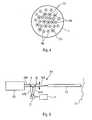
- the fifth doppler spectrum measurement techniquewhich can be implemented by a device D3 shown in Figure 6 (and integrated in system 1), allows to know the distribution of the speeds of the blood flow in the various capillaries of the living tissue Tv analyzed. It is based on the analysis of the radio frequency spectrum of interference beat between the wave backscattered by moving red blood cells in the capillaries and the wave emitted at the input of the measuring optical fiber F0. This optical beat is easily obtained when using the same F0 optical fiber for transmission and reception, thanks to two separating plates 9 and 10 superimposing the two LEO light signals and LRO on the input face of an optical sensor Ci (avalanche photodiode or photomultiplier).
- Cioptical photodiode or photomultiplier
- the sixth techniqueconsists of measure the change in pressure in the blood vessels.
- TvWhen the living tissue Tv is illuminated by a light laser beam having a wavelength suitable for penetrating to the blood vessels (about 800 nm), the deformation of these vessels by the pressure causes a correlative variation in backscattered light in time.
- a device which is similarcan be used for this. to that D1 represented in FIG. 2.
Landscapes
- Life Sciences & Earth Sciences (AREA)
- Health & Medical Sciences (AREA)
- Medical Informatics (AREA)
- Biophysics (AREA)
- Pathology (AREA)
- Engineering & Computer Science (AREA)
- Biomedical Technology (AREA)
- Heart & Thoracic Surgery (AREA)
- Physics & Mathematics (AREA)
- Molecular Biology (AREA)
- Surgery (AREA)
- Animal Behavior & Ethology (AREA)
- General Health & Medical Sciences (AREA)
- Public Health (AREA)
- Veterinary Medicine (AREA)
- Investigating Or Analysing Materials By Optical Means (AREA)
- Investigating, Analyzing Materials By Fluorescence Or Luminescence (AREA)
Abstract
Description
Translated fromFrenchLa présente invention concerne un système d'analyse optique d'untissu vivant.The present invention relates to an optical analysis system of aliving tissue.
Bien que non exclusivement, ce système d'analyse optique estdestiné plus particulièrement à rechercher par voie optique une pathologiespécifique, par exemple un cancer, sur un tissu humain, c'est-à-dire sur unorgane du corps humain tel qu'un poumon ou le foie par exemple.Although not exclusively, this optical analysis system isintended more particularly to search optically for a pathologyspecific, for example cancer, on human tissue, that is to say on aorgan of the human body such as a lung or the liver for example.
A cet effet, il est bien connu, dans le domaine du diagnostic médicalpar voie optique, d'illuminer un tissu vivant humain à analyser par unfaisceau lumineux de faible puissance en provenance soit de sources lumineusesusuelles, soit de sources laser, et d'effectuer, par l'analyse d'unrayonnement lumineux induit qui est ré-émis par le tissu vivant ainsi illuminé,une mesure physique caractéristique d'un paramètre physiologiqueparticulier relatif à la pathologie recherchée de manière à pouvoir en déduirela présence ou non de cette pathologie sur ce tissu humain.For this purpose, it is well known in the field of medical diagnosisoptically, to illuminate a living human tissue to be analyzed by alow-power light beam from either light sourcesusual, either from laser sources, and to perform, by the analysis of ainduced light radiation which is re-emitted by the living tissue thus illuminated,a physical measurement characteristic of a physiological parameterparticular relating to the pathology sought so as to be able to deduce therefromthe presence or not of this pathology on this human tissue.
Généralement, un dispositif destiné à réaliser une telle analyseoptique comporte, de façon connue :
- au moins une source lumineuse susceptible d'engendrer au moins unfaisceau lumineux ;
- au moins une première fibre optique (d'émission) susceptible de transmettreun faisceau lumineux engendré par ladite source lumineuse sur letissu vivant à analyser ;
- au moins une seconde fibre optique (de réception) susceptible de recevoiret de transmettre un rayonnement lumineux provenant dudit tissuvivant illuminé par ledit faisceau lumineux ;
- au moins un capteur optique qui est susceptible de mesurer un paramètreparticulier dudit rayonnement lumineux transmis par ladite secondefibre optique ; et
- un moyen de traitement pour émettre, au moins en fonction des mesuresréalisées par ledit capteur optique, une information positive ou négativesur la présence d'une pathologie particulière sur ledit tissu vivantanalysé.
- at least one light source capable of generating at least one light beam;
- at least a first optical fiber (emission) capable of transmitting a light beam generated by said light source on the living tissue to be analyzed;
- at least a second optical fiber (receiving) capable of receiving and transmitting light radiation from said living tissue illuminated by said light beam;
- at least one optical sensor which is capable of measuring a particular parameter of said light radiation transmitted by said second optical fiber; and
- processing means for transmitting, at least as a function of the measurements carried out by said optical sensor, positive or negative information on the presence of a particular pathology on said living tissue analyzed.
Une telle analyse par voie optique, pour laquelle il suffit généralementd'amener au contact ou à proximité du tissu à analyser lesdites fibresoptiques qui ont en général un diamètre d'environ un millimètre, présente,en raison de sa très faible invasivité, un avantage important, à savoirune grande tolérance de la part des patients, par rapport notammentaux biopsies qui sont généralement réalisées sur les tissus vivants. Unautre avantage d'une analyse par voie optique réside dans la rapidité parlaquelle est établi un résultat, généralement dès la fin de l'analyse, alorsqu'une attente de plusieurs jours est le plus souvent nécessaire pourobtenir les résultats de traitements réalisés sur des tissus prélevés lorsd'une biopsie.Such an optical analysis, for which it is generally sufficientto bring into contact or near the tissue to be analyzed said fibersoptics which generally have a diameter of about one millimeter, present,due to its very low invasiveness, an important advantage, namelya great tolerance on the part of the patients, compared in particularbiopsies that are usually done on living tissue. Aanother advantage of an optical analysis is the speed bywhich is established a result, generally at the end of the analysis, thenthat a wait of several days is most often necessary toobtain the results of treatments performed on tissues removed duringa biopsy.
Toutefois, une analyse par voie optique du type précité présenteégalement un inconvénient important, souvent rédhibitoire, à savoir untaux très élevé de faux diagnostics. Des faux diagnostics sont bienentendu difficilement acceptables par les patients et par le corps médical,notamment lorsqu'ils concernent des pathologies graves telles qu'un cancerpar exemple.However, an optical analysis of the aforementioned type presentsalso a major drawback, often prohibitive, namely avery high rate of false diagnoses. False diagnoses are goodheard difficult to accept by patients and the medical profession,especially when they concern serious pathologies such as cancerfor example.
Dans le cadre de la présente invention, on entend par taux de fauxnégatifs le pourcentage statistique d'indication d'un diagnostic négatifd'une pathologie donnée, alors qu'un contrôle postérieur par des méthodesusuelles telles qu'une biopsie par exemple, indique la présence réellede cette pathologie.In the context of the present invention, the term false ratenegative the statistical percentage of indication of a negative diagnosisof a given pathology, while a subsequent control by methodsusual such as a biopsy for example, indicates the actual presenceof this pathology.
On présente ci-après, à titre d'illustration, différentes techniquesd'analyse optique connues, avec le taux de faux négatifs correspondants.Various techniques are presented below by way of illustration.optical analysis known, with the corresponding false negative rate.
Une première technique d'analyse connue, qui est notamment décritedans le brevet US-4 930 516, consiste à induire une fluorescenceendogène dans le tissu vivant à l'aide d'un faisceau lumineux présentantune longueur d'onde adaptée. Comme premier exemple de diagnosticsusceptible d'être effectué à partir de cette analyse optique, on peut citerle cas du cancer de l'oesophage. A cet effet, la lumière d'excitation estengendrée par un laser à colorant émettant à 410 nm à travers la fibreoptique et le diagnostic est obtenu par une analyse différentielle normaliséedes spectres de fluorescence endogène du tissu vivant en cause. Dansce cas, on obtient couramment des taux de faux négatifs de plusieurspour cent. Dans un deuxième exemple qui est relatif à l'analyse du cancerdu col de l'utérus, pour laquelle l'excitation optique est engendrée par unlaser à azote émettant à 337 nm et le diagnostic est effectué par l'analysede la pente de fluorescence endogène, on obtient des taux de faux négatifsde dix pour cent. Ce dernier exemple est caractéristique d'une situationtotalement inacceptable pour un médecin, pour laquelle une patientesur dix verra son cancer s'aggraver dans l'avenir, car il n'a pu être détectépar la technique d'analyse utilisée.A first known analysis technique, which is notably describedin US Pat. No. 4,930,516, consists in inducing fluorescenceendogenous in living tissue using a light beam presentinga suitable wavelength. As a first diagnostic examplelikely to be carried out from this optical analysis, we can citethe case of esophageal cancer. The excitation light is thereforegenerated by a dye laser emitting at 410 nm through the fiberoptics and the diagnosis is obtained by a standardized differential analysisendogenous fluorescence spectra of the living tissue in question. Inthis case, we often obtain false negative rates of severalpercent. In a second example which relates to the analysis of cancerof the cervix, for which optical excitation is generated by anitrogen laser emitting at 337 nm and diagnosis is made by analysisof the endogenous fluorescence slope, we obtain false negative ratesten percent. This last example is characteristic of a situationtotally unacceptable to a doctor, for which a patientin ten will see their cancer worsen in the future because it could not be detectedby the analysis technique used.
Une autre technique connue consiste à analyser l'amplitude de lalumière rétrodiffusée par le tissu vivant en fonction de la longueur d'ondeémise. Comme exemple de diagnostic, on peut citer dans ce cas la recherched'un cancer du foie, pour laquelle la source lumineuse émet une lumièreblanche couvrant l'ensemble du spectre visible de 300 nm à 750nm, les fibres d'émission sont au contact du tissu suspect, les fibres deréception sont également au contact du tissu au voisinage des fibresd'émission, et le diagnostic est obtenu par l'analyse spectrale de la lumièrede diffusion élastique des photons diffusés dans le tissu. Avec cette dernière technique, il est courant d'obtenir des taux de faux négatifs detrois pour cent.Another known technique consists in analyzing the amplitude of thelight backscattered by living tissue as a function of wavelengthissued. As an example of diagnosis, we can cite in this case researchliver cancer, for which the light source emits lightwhite covering the entire visible spectrum from 300 nm to 750nm, the emission fibers are in contact with the suspect tissue, thereception are also in contact with the fabric in the vicinity of the fibersemission, and the diagnosis is obtained by spectral analysis of the lightof elastic diffusion of the photons scattered in the tissue. With thislast technique it's common to get false negative rates ofthree percent.
Aucun de ces dispositifs ou méthodes d'analyse optique connusne présente donc une fiabilité suffisante pour permettre au corps médicald'accorder une confiance totale à ses résultats. Ces dispositifs usuelsd'analyse optique peuvent, tout au plus, servir à conforter un résultatobtenu par un autre type d'analyse beaucoup plus fiable.None of these known optical analysis devices or methodstherefore does not have sufficient reliability to allow the medical professionto give total confidence to its results. These usual devicesoptical analysis can, at most, be used to confirm a resultobtained by another much more reliable type of analysis.
La présente invention a pour objet de remédier aux inconvénientsprécités. Elle concerne un système d'analyse optique d'un tissu vivant,notamment du corps humain, qui est peu invasif et très fiable.The object of the present invention is to remedy the drawbackssupra. It concerns a system for optical analysis of living tissue,especially the human body, which is minimally invasive and very reliable.
A cet effet, selon l'invention, ledit système d'analyse optique d'untissu vivant, comportantn dispositifs d'analyse optique qui sont susceptiblesde mettre en oeuvre des techniques d'analyse différentes,n étant unentier supérieur ou égal à 3, et une unité centrale, chacun desdits dispositifsd'analyse optique mettant en oeuvre, lorsqu'il est déclenché, unetechnique d'analyse particulière du tissu vivant de manière à pouvoirémettre une information positive ou négative sur la présence d'une pathologieparticulière sur ledit tissu vivant et comprenant :
- au moins une source lumineuse susceptible d'engendrer au moins unfaisceau lumineux ;
- au moins une première fibre optique susceptible de transmettre unfaisceau lumineux engendré par ladite source lumineuse, sur un tissuvivant à analyser ;
- au moins une seconde fibre optique susceptible de recevoir et de transmettreun rayonnement lumineux provenant dudit tissu vivant illuminépar ledit faisceau lumineux ;
- au moins un capteur optique susceptible de mesurer un paramètre particulierdudit rayonnement lumineux transmis par ladite seconde fibreoptique ; et
- un moyen de traitement pour émettre, au moins en fonction des mesuresréalisées par ledit capteur optique, une information positive ou négativesur la présence d'une pathologie particulière sur ledit tissu vivantanalysé,
- des moyens de sélection actionnables, pour sélectionner un nombre pdesditsn dispositifs d'analyse optique différents,p étant un entier supérieurà 1 et inférieur àn ; et
- des moyens de déclenchement actionnables, pour déclencher chacundesp dispositifs d'analyse optique qui ont été sélectionnés par l'inter-médiairedesdits moyens de sélection de sorte que chacun d'eux met enoeuvre sa technique d'analyse particulière et émet une information positiveou négative sur la présence d'une pathologie,
- at least one light source capable of generating at least one light beam;
- at least a first optical fiber capable of transmitting a light beam generated by said light source, on a living tissue to be analyzed;
- at least a second optical fiber capable of receiving and transmitting light radiation from said living tissue illuminated by said light beam;
- at least one optical sensor capable of measuring a particular parameter of said light radiation transmitted by said second optical fiber; and
- a processing means for transmitting, at least as a function of the measurements carried out by said optical sensor, positive or negative information on the presence of a particular pathology on said living tissue analyzed,
- actuatable selection means for selecting a number p of saidn different optical analysis devices,p being an integer greater than 1 and less thann ; and
- actuatable trigger means, for triggering each of thep optical analysis devices which have been selected by means of said selection means so that each of them implements its particular analysis technique and transmits information positive or negative on the presence of a pathology,
Ainsi, grâce à l'invention, ledit système présente les avantagesprécités (invasivité réduite, résultat rapide) des dispositifs d'analyse optique.Thus, thanks to the invention, said system has the advantagescited above (reduced invasiveness, rapid result) of optical analysis devices.
De plus, comme l'absence d'une pathologie est diagnostiquée uniquementsi plusieurs (un nombreq de) dispositifs d'analyse optique ontdétecté simultanément l'absence de cette pathologie, ledit système estparticulièrement fiable. En tout cas, l'invention est réalisée, comme on leverra plus en détail ci-dessous, pour que le taux de faux diagnostics pathologiquesnégatifs soit inférieur au taux (généralement de l'ordre de unpour cent) requis dans la profession médicale.In addition, since the absence of a pathology is diagnosed only if several (a numberq of) optical analysis devices have simultaneously detected the absence of this pathology, said system is particularly reliable. In any case, the invention is made, as will be seen in more detail below, so that the rate of false negative pathological diagnoses is lower than the rate (generally of the order of one percent) required in the medical profession .
Dans un mode de réalisation préféré, l'entierq est supérieur à p/2,et ladite unité centrale est, de plus, telle que si les moyens de traitementd'au moinsq desditsp dispositifs d'analyse optique qui ont été sélectionnéset déclenchés, ont émis une information positive, elle émet undiagnostic positif sur la présence de ladite pathologie sur ledit tissu vivant.In a preferred embodiment, the integerq is greater than p / 2, and said central unit is also such that if the processing means of at leastq of saidp optical analysis devices which have been selected and triggered, have issued positive information, it emits a positive diagnosis on the presence of said pathology on said living tissue.
Ainsi, le système conforme à l'invention est en mesure de diagnostiquerde façon fiable, non seulement l'absence d'une pathologie sur untissu vivant, mais également sa présence.Thus, the system according to the invention is able to diagnosereliably, not only the absence of pathology on aliving tissue, but also its presence.
De préférence,q est égal àp de sorte que l'absence (ou la présence)d'une pathologie est diagnostiquée si et uniquement si tous lespdispositifs d'analyse optique sélectionnés et déclenchés ont tous émis uneinformation négative (ou une information positive) sur la présence de cettepathologie.Preferably,q is equal top so that the absence (or the presence) of a pathology is diagnosed if and only if all thep optical analysis devices selected and triggered have all sent negative information (or information positive) on the presence of this pathology.
De façon avantageuse, toutes lesdites première et seconde fibresoptiques desditsn dispositifs d'analyse optique sont agencées dans uneseule et même gaine souple présentant un diamètre qui est inférieur à unevaleur de diamètre maximale, de préférence deux millimètres. Ceci permetnotamment d'utiliser ladite gaine dans des endoscopes médicaux usuels.Advantageously, all of said first and second optical fibers of saidn optical analysis devices are arranged in a single flexible sheath having a diameter which is less than a maximum diameter value, preferably two millimeters. This allows in particular to use said sheath in conventional medical endoscopes.
Par ailleurs, avantageusement :
- au moins l'une desdites sources lumineuses engendre un faisceau lumineux,dont le spectre optique recouvre sensiblement l'ensemble duspectre visible ; et/ou
- au moins l'une desdites sources lumineuses comporte une pluralité delasers, dont chacun engendre un faisceau lumineux présentant uneseule longueur d'onde qui est différente de celles des autres lasers.
- at least one of said light sources generates a light beam, the optical spectrum of which substantially covers the entire visible spectrum; and or
- at least one of said light sources comprises a plurality of lasers, each of which generates a light beam having a single wavelength which is different from those of other lasers.
En outre, de façon avantageuse, au moins l'un desdits capteursoptiques comporte au moins l'un des moyens suivants :
- une photodiode ;
- un photomultiplicateur ; et
- un spectrographe.
- a photodiode;
- a photomultiplier; and
- a spectrograph.
Dans un mode de réalisation particulier, lesdits moyens de sélectionpermettent (à un opérateur, par exemple un médecin) de choisir unepathologie particulière et ils sélectionnent automatiquementp dispositifsd'analyse optique qui sont associés au choix de cette pathologie particulière.Ainsi, pour rechercher une pathologie particulière chez un être humain,un médecin aura juste :
- à choisir (par l'intermédiaire des moyens de sélection) la pathologie qu'ilsoupçonne (par exemple un cancer de l'oesophage) ;
- à disposer l'extrémité distale des fibres optiques au contact de la lésionsuspectée, en particulier par l'intermédiaire de moyens appropriés etconnus tels qu'un endoscope par exemple ; et
- à déclencher l'analyse et le diagnostic (par l'intermédiaire desditsmoyens de déclenchement).
- to choose (by means of selection) the pathology which he suspects (for example cancer of the esophagus);
- placing the distal end of the optical fibers in contact with the suspected lesion, in particular by means of suitable and known means such as an endoscope for example; and
- to trigger the analysis and the diagnosis (by means of said triggering means).
Dans un mode de réalisation préféré, le système conforme à l'inventioncomporte au moins six dispositifs d'analyse optique différents, quimettent en oeuvre des techniques d'analyse particulières, pour analyserrespectivement sur le tissu vivant :
- la fluorescence, endogène ou exogène ;
- la diffusion optique élastique multispectrale ;
- l'ischémie tissulaire ;
- l'oxymétrie sanguine ;
- le spectre doppler de l'écoulement sanguin ; et
- la photopléthysmographie vasculaire.
- fluorescence, endogenous or exogenous;
- multispectral elastic optical scattering;
- tissue ischemia;
- blood oximetry;
- the Doppler spectrum of blood flow; and
- vascular photoplethysmography.
Selon l'invention, dans ce cas, pour rechercher :
- un cancer de l'oesophage, les dispositifs d'analyse optique analysantrespectivement la fluorescence, la diffusion optique élastique multispectraleet le spectre doppler de l'écoulement sanguin sont sélectionnés ;
- un cancer du poumon, les dispositifs d'analyse optique analysant respectivementla fluorescence, la diffusion optique élastique multispectraleet le spectre doppler de l'écoulement sanguin sont sélectionnés ;
- un cancer du foie, les dispositifs d'analyse optique analysant respectivementla diffusion optique élastique multispectrale, l'oxymétrie sanguineet la photopléthysmographie vasculaire sont sélectionnés ;
- un mélanome de la peau, les dispositifs d'analyse optique analysantrespectivement la diffusion optique élastique multispectrale, l'oxymétriesanguine et le spectre doppler de l'écoulement sanguin sont sélectionnés;
- un cancer de la vessie, les dispositifs d'analyse optique analysant respectivementla fluorescence endogène, la diffusion optique élastiquemultispectrale et la photopléthysmographie vasculaire sont sélectionnés;
- un infarctus du myocarde, les dispositifs d'analyse optique analysantrespectivement l'ischémie tissulaire, l'oxymétrie sanguine et la photopléthysmographievasculaire sont sélectionnés ;
- un cancer neurologique, les dispositifs d'analyse optique analysant respectivementla fluorescence, la diffusion optique élastique multispectraleet le spectre doppler de l'écoulement sanguin sont sélectionnés ;
- un cancer ORL, les dispositifs d'analyse optique analysant respectivementla diffusion optique élastique multispectrale, l'ischémie tissulaireet le spectre doppler de l'écoulement sanguin sont sélectionnés ;
- un cancer du col, les dispositifs d'analyse optique analysant respectivementla fluorescence, la diffusion optique élastique multispectrale etla photopléthysmographie sont sélectionnés ;
- une inflammation bactérienne, les dispositifs d'analyse optique analysantrespectivement la fluorescence, le spectre doppler de l'écoulementsanguin et la photopléthysmographie sont sélectionnés ; et
- une brûlure, les dispositifs d'analyse optique analysant respectivementla fluorescence, l'oxymétrie sanguine et le spectre doppler de l'écoulementsanguin sont sélectionnés.
- esophageal cancer, optical analysis devices that analyze fluorescence, multispectral elastic optical scattering and the doppler spectrum of blood flow, respectively;
- lung cancer, the optical analysis devices analyzing respectively the fluorescence, the multispectral elastic optical scattering and the doppler spectrum of the blood flow are selected;
- liver cancer, optical analysis devices analyzing respectively multispectral elastic optical scattering, blood oximetry and vascular photoplethysmography are selected;
- a melanoma of the skin, the optical analysis devices respectively analyzing the multispectral elastic optical scattering, the blood oximetry and the doppler spectrum of the blood flow are selected;
- bladder cancer, optical analysis devices analyzing endogenous fluorescence, multispectral elastic optical scattering and vascular photoplethysmography, respectively;
- myocardial infarction, the optical analysis devices respectively analyzing tissue ischemia, blood oximetry and vascular photoplethysmography are selected;
- neurological cancer, the optical analysis devices analyzing respectively the fluorescence, the multispectral elastic optical scattering and the doppler spectrum of the blood flow are selected;
- ENT cancer, optical analysis devices respectively analyzing multispectral elastic optical scattering, tissue ischemia and the doppler spectrum of blood flow are selected;
- cervical cancer, optical analysis devices analyzing fluorescence, multispectral elastic optical scattering and photoplethysmography, respectively;
- bacterial inflammation, the optical analysis devices analyzing respectively the fluorescence, the doppler spectrum of the blood flow and the photoplethysmography are selected; and
- a burn, the optical analysis devices respectively analyzing the fluorescence, the blood oximetry and the doppler spectrum of the blood flow are selected.
Les figures du dessin annexé feront bien comprendre commentl'invention peut être réalisée. Sur ces figures, des références identiquesdésignent des éléments semblables.
Selon l'invention, ledit système 1 comporte :
- un ensemble E den dispositifs d'analyse optique D1 à Dn, de typeusuel,n étant un entier supérieur ou égal à 3. Cet ensemble E comportenotamment un ensemble E1 de sources lumineuses, un ensemble E2 depremières fibres optiques (d'émission), un ensemble E3 de secondes fibresoptiques (de réception) et un ensemble E4 de capteurs optiques,comme précisé ci-dessous. Chacun desdits dispositifs d'analyse optiqueD1 à Dn est susceptible de mettre en oeuvre une technique d'analyse particulière du tissu vivant Tv de manière à pouvoir émettre une informationpositive ou négative sur la présence d'une pathologie particulièresur ledit tissu vivant Tv ;
- des moyens de sélection 2 actionnables par un opérateur, en particulierun médecin, pour sélectionner un nombrep desditsn dispositifs d'analyseoptique D1 à Dn,p étant un entier supérieur à 1 et inférieur àn ;
- des moyens de déclenchement 3 actionnables par un opérateur, pourdéclencher chacun desp dispositifs d'analyse optique qui ont été sélectionnéspar l'intermédiaire desdits moyens de sélection 2 de sorte quechacun d'eux met alors en oeuvre sa technique d'analyse particulière etémet une information positive ou négative sur la présence d'une pathologieparticulière ; et
- une unité centrale 4 qui est telle que si au moinsq desditsp dispositifsqui ont été sélectionnés et déclenchés,q étant un entier supérieur à 1et inférieur ou égal àp, ont émis une information négative, elle émet undiagnostic négatif sur la présence de ladite pathologie sur le tissu vivantTv analysé.
- a set E ofn optical analysis devices D1 to Dn, of the usual type,n being an integer greater than or equal to 3. This set E comprises in particular a set E1 of light sources, a set E2 of first optical fibers (of transmission), a set E3 of second optical fibers (for reception) and a set E4 of optical sensors, as specified below. Each of said optical analysis devices D1 to Dn is capable of implementing a particular analysis technique of living tissue Tv so as to be able to emit positive or negative information on the presence of a particular pathology on said living tissue Tv;
- selection means 2 operable by an operator, in particular a doctor, for selecting a numberp of saidn optical analysis devices D1 to Dn,p being an integer greater than 1 and less thann ;
- trigger means 3 operable by an operator, to trigger each of thep optical analysis devices which have been selected by means of said selection means 2 so that each of them then implements its particular analysis technique and issues positive or negative information on the presence of a particular pathology; and
- a
central processing unit 4 which is such that if at leastq of saidp devices which have been selected and triggered,q being an integer greater than 1 and less than or equal top , have sent negative information, it emits a negative diagnosis on the presence of said pathology on the living tissue Tv analyzed.
Ainsi, comme grâce à l'invention, l'absence d'une pathologie estuniquement diagnostiquée si une pluralité deq dispositifs d'analyse optiqueD1, D2, ..., Dn ont détecté simultanément l'absence de cette pathologie,le système 1 est particulièrement fiable. En tout cas, l'invention estréalisée, comme on le verra plus en détail ci-dessous, pour que le taux defaux diagnostics pathologiques négatifs soient inférieur au taux (un pourcent environ) requis dans la profession médicale.Thus, as thanks to the invention, the absence of a pathology is only diagnosed if a plurality ofq optical analysis devices D1, D2, ..., Dn have simultaneously detected the absence of this pathology, the
Dans un mode de réalisation préféré, l'entierq est supérieur à p/2,et, si les moyens de traitement d'au moinsq desditsp dispositifs d'analyseoptique qui ont été sélectionnés et déclenchés, ont émis une informationpositive, ladite unité centrale 4 émet un diagnostic positif sur la présencede ladite pathologie sur ledit tissu vivant.In a preferred embodiment, the integerq is greater than p / 2, and, if the means for processing at leastq of saidp optical analysis devices which have been selected and triggered, have sent positive information, said
Ainsi, le système 1 conforme à l'invention est en mesure dediagnostiquer de façon fiable, non seulement l'absence d'une pathologiesur un tissu vivant Tv, mais également sa présence.Thus, the
De préférence,q est égal àp de sorte que l'absence (ou la présence)d'une pathologie est diagnostiquée si et uniquement si tous lespdispositifs d'analyse optique sélectionnés et déclenchés ont émis uneinformation négative (ou une information positive) sur la présence de cettepathologie.Preferably,q is equal top so that the absence (or the presence) of a pathology is diagnosed if and only if all thep optical analysis devices selected and triggered have sent negative information (or positive information ) on the presence of this pathology.
Lesdits dispositifs d'analyse optique D1 à Dn, de type usuel, présententtous au moins les caractéristiques générales représentées à titred'illustration pour un dispositif D1 sur la figure 2, c'est-à-dire ils comprennenttous :
- au moins une source lumineuse Si susceptible d'engendrer au moins unfaisceau lumineux LEi ;
- au moins une première fibre optique FEi susceptible de transmettre surun tissu vivant Tv un faisceau lumineux LEi engendré par ladite sourcelumineuse Si et reçu par l'intermédiaire d'un moyen (lentille) de focalisationMi ;
- au moins une seconde fibre optique FRi susceptible de recevoir et detransmettre un rayonnement lumineux LRi provenant dudit tissu vivantTv éclairé par ledit faisceau lumineux LEi ;
- au moins un capteur optique Ci qui est susceptible de mesurer un paramètreparticulier dudit rayonnement lumineux LRi transmis par laditeseconde fibre optique FRi, via un moyen (lentille) de focalisation Ni ; et
- un moyen de traitement Ti pour émettre, au moins en fonction des mesuresréalisées par ledit capteur optique Ci, une information positive ounégative sur la présence d'une pathologie particulière sur ledit tissu vivantTv analysé.
- at least one light source Si capable of generating at least one light beam LEi;
- at least a first optical fiber FEi capable of transmitting on a living tissue Tv a light beam LEi generated by said light source Si and received by means of focusing means (lens) Mi;
- at least one second optical fiber FRi capable of receiving and transmitting light radiation LRi coming from said living tissue Tv illuminated by said light beam LEi;
- at least one optical sensor Ci which is capable of measuring a particular parameter of said light radiation LRi transmitted by said second optical fiber FRi, via a means (lens) of focusing Ni; and
- a processing means Ti for transmitting, at least as a function of the measurements carried out by said optical sensor Ci, positive or negative information on the presence of a particular pathology on said living tissue Tv analyzed.
Par conséquent, le faisceau lumineux LEi qui est engendré par lasource lumineuse Si est amené sur le tissu vivant Tv, via la lentille de focalisationMi et la fibre optique FEi. En pénétrant dans le tissu vivant Tv,ce faisceau lumineux LEi y induit un phénomène optique (par exemple unefluorescence qui est émise à des longueurs d'onde supérieures à celle dufaisceau lumineux LEi ou une rétrodiffusion à la même longueur d'onde,dont l'analyse de l'amplitude ou de la modulation de fréquence par effetdoppler permet de réaliser le diagnostic recherché) qui engendre un nouveaurayonnement lumineux, dont une partie LRi est amenée au moyen detraitement Ti, via la fibre optique FRi et la lentille de focalisation Ni, pour yêtre analysée. La comparaison des caractéristiques de ce rayonnementlumineux LRi induit et de celles du faisceau lumineux LEi initial permet dedéduire, en fonction de techniques d'analyse particulières connues et préciséesci-dessous, la présence ou non d'une pathologie particulière.Consequently, the light beam LEi which is generated by thelight source Si is brought onto the living tissue Tv, via the focusing lensMi and FEi optical fiber. By entering the living tissue Tv,this light beam LEi induces there an optical phenomenon (for example afluorescence which is emitted at wavelengths greater than that of theLEi light beam or backscatter at the same wavelength,including analysis of amplitude or frequency modulation by effectdoppler makes it possible to carry out the desired diagnosis) which generates a newlight radiation, part of which LRi is supplied by means ofTi treatment, via the optical fiber FRi and the focusing lens Ni, for ybe analyzed. Comparing the characteristics of this radiationinduced light LRi and those of the initial light beam LEi makes it possible todeduce, according to specific and known specific analysis techniquesbelow, the presence or absence of a particular pathology.
Ainsi, grâce à l'invention, ledit système 1 présente tous les avantagesdes dispositifs d'analyse optique usuels, du type de celui D1 représentésur la figure 2, à savoir notamment une invasivité réduite et des résultatsobtenus rapidement.Thus, thanks to the invention, said
Comme on le verra plus en détail ci-dessous :
- ladite source lumineuse Si peut comporter :
- une source Sb (par exemple une lampe à filament de tungstène halogène)émettant une lumière blanche LEb, c'est-à-dire présentant unspectre optique très large couvrant au moins le spectre visible, maispouvant s'étendre du proche ultraviolet (300 nm environ) au procheinfrarouge (1500 nm environ) ; ou
- une seule source laser S1 ; ou
- une pluralité de sources laser S1 à SI émettant chacune un faisceaulumineux LE1 à LEI présentant une longueur d'onde particulière. Lessources laser SO et S1 à SI peuvent être de tout type connu, par exemple de simples diodes laser, des diodes laser doublées en fréquenceou un laser solide pompé par diodes et doublé ou triplé enfréquence ; et
- au moins l'un desdits capteurs optiques Ci peut comporter au moinsl'un des moyens suivants :
- une photodiode ;
- un photomultiplicateur ; et
- un spectrographe.
- said light source Si may include:
- a source Sb (for example a halogen tungsten filament lamp) emitting white light LEb, that is to say having a very wide optical spectrum covering at least the visible spectrum, but which can extend from the near ultraviolet (300 about nm) at near infrared (about 1500 nm); or
- a single laser source S1; or
- a plurality of laser sources S1 to SI each emitting a light beam LE1 to LEI having a particular wavelength. The laser sources SO and S1 to SI can be of any known type, for example simple laser diodes, laser diodes doubled in frequency or a solid laser pumped by diodes and doubled or tripled in frequency; and
- at least one of said optical sensors Ci can comprise at least one of the following means:
- a photodiode;
- a photomultiplier; and
- a spectrograph.
De préférence, les moyens 2 et 3 et l'unité centrale 4 sont intégrésdans un ordinateur 5, notamment un "ordinateur personnel". De plus,les sources lumineuses Si ont leur alimentation propre (non représentée)sous le contrôle d'un bloc de commande (non représenté) qui est lui mêmeactivé par l'ordinateur 5. Les divers signaux délivrés par les capteurs optiquesCi préalablement activés par l'ordinateur 5 sont d'abord archivéssous forme digitale, avant d'être analysés par le programme approprié situédans l'unité centrale 4 de l'ordinateur 5. Cette dernière compareensuite ces résultats avec les données qu'elle a en mémoire pour les pathologiesconsidérées afin de délivrer un diagnostic. A cet effet, l'ordinateur5 est associé à (ou comprend) un moyen 6 de visualisation dudiagnostic, par exemple un écran de visualisation ou une imprimante quifournit les résultats sur un support papier.Preferably, the
Dans le mode de réalisation préféré représenté partiellement sur lafigure 3, ledit système 1 comporte :
- une source Sb de lumière blanche qui est associée à un moyen de focalisationMb et à une fibre optique FEb ;
- des sources laser SO et S1 à Sl (S1, S2, ..., Sj, Sj+1, ..., Sl) qui sontassociées respectivement à des moyens de focalisation M0 et M1 à M1et à des fibres optiques F0 et FE1 à FEI. On notera que l'entier estcompris entre 2 et (l-1) ;
- un spectrographe CO qui est associé à des fibres optiques FRO ; et
- des capteurs optiques C1 à Cm (C1, ..., Ck, Ck+1, ..., Cm) qui sontassociés à des fibres optiques FR1 à FRm. On notera que l'entierk estcompris entre 1 et (m-1).
- a source Sb of white light which is associated with a focusing means Mb and an optical fiber FEb;
- laser sources SO and S1 to Sl (S1, S2, ..., Sj, Sj + 1, ..., Sl) which are associated respectively with focusing means M0 and M1 to M1 and with optical fibers F0 and FE1 to FEI. Note that the integer is between 2 and (l-1);
- a CO spectrograph which is associated with FRO optical fibers; and
- optical sensors C1 to Cm (C1, ..., Ck, Ck + 1, ..., Cm) which are associated with optical fibers FR1 to FRm. Note that the integerk is between 1 and (m-1).
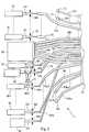
De plus, toutes les fibres optiques, c'est-à-dire aussi bien les fibresoptiques d'émission FEi (FEb, F0 et FE1 à FEI) que les fibres optiques deréception FRi (FO et FR0 à FRm), sont agencées, comme montré sur lafigure 4, dans une seule et même gaine souple 7 présentant un diamètrequi est inférieur à une valeur de diamètre maximale, de préférence deuxmillimètres. Ce diamètre est généralement requis pour pouvoir pénétrerdans le canal opératoire d'endoscopes ou de coelioscopes médicaux.In addition, all optical fibers, i.e. both fibersFEi emission optics (FEb, F0 and FE1 to FEI) than the optical fibers ofFRi reception (FO and FR0 to FRm), are arranged, as shown on theFigure 4, in a single
Dans un mode de réalisation particulier, lesdits moyens de sélection2 permettent à un opérateur de choisir (par exemple manuellement ouvocalement) une pathologie particulière et ils sélectionnent automatiquementp dispositifs d'analyse optique particuliers, qui sont associés auchoix de cette pathologie particulière. Ainsi, dans ce cas, pour rechercherune pathologie particulière chez un être humain, un opérateur, notammentun médecin, aura juste :
- à choisir (par l'intermédiaire des moyens de sélection 2) la pathologiequ'il soupçonne (par exemple un cancer de l'oesophage) ;
- à disposer l'extrémité distale des fibres optiques FEi et FRi (c'est-à-direde la gaine 7) au contact de la lésion suspectée (tissu Tv), en particulierpar l'intermédiaire de moyens appropriés et connus tels qu'un endoscopepar exemple ; et
- à déclencher l'analyse et le diagnostic (par l'intermédiaire desditsmoyens de déclenchement 3).
- to choose (via selection means 2) the pathology he suspects (for example cancer of the esophagus);
- placing the distal end of the optical fibers FEi and FRi (that is to say the sheath 7) in contact with the suspected lesion (Tv tissue), in particular by means of suitable and known means such as an endoscope for example; and
- to trigger the analysis and the diagnosis (by means of said triggering means 3).
Dans un mode de réalisation préféré, le système 1 comporte aumoins six dispositifs d'analyse optique différents et connus, qui mettent en oeuvre des techniques d'analyse particulières pour analyser, respectivement,sur le tissu vivant Tv :
- la fluorescence endogène ;
- la diffusion optique élastique multispectrale ;
- l'ischémie tissulaire ;
- l'oxymétrie sanguine ;
- le spectre doppler de l'écoulement sanguin ; et
- la photopléthysmographie vasculaire.
- endogenous fluorescence;
- multispectral elastic optical scattering;
- tissue ischemia;
- blood oximetry;
- the Doppler spectrum of blood flow; and
- vascular photoplethysmography.
Dans ce cas, selon l'invention, en fonction de la pathologie recherchée,on met en oeuvre à chaque fois trois techniques d'analyse spécifiques,parmi les six techniques d'analyse particulières précitées, tel quereprésenté sur le tableau suivant.
On précise à présent les techniques d'analyse connues précitées.The above-mentioned known analysis techniques are now specified.
La première technique d'analyse précitée peut être mise en oeuvrepar un dispositif D2 représenté sur la figure 5 (et intégré dans le système1) et consiste à analyser la fluorescence, endogène ou exogène, des tissussuspects avec un laser Si de longueur d'onde appropriée qui, pour le casdu cancer de l'oesophage par exemple, est un laser ultraviolet émettant à350 nm. Pour cet exemple, le spectre de fluorescence est analysé entre390 et 550 nm. Pour des maladies inflammatoires, on utilise par exempleun laser Si émettant dans le vert et on examine la fluorescence des porphyrinesdans la partie rouge du spectre. Sur la figure 5, on peut voir queles fibres de réception FR0 sont beaucoup plus nombreuses (environ 10)et entourent la fibre d'émission FEi au niveau de l'extrémité distale dufaisceau de fibres, car le niveau du signal de fluorescence est beaucoupplus faible qu'une rétrodiffusion à la même longueur d'onde. Ainsi, pourrechercher simultanément les deux pathologies indiquées ci-dessus, le système1 comporte, dans un mode de réalisation particulier non représenté,à l'extrémité distale, deux fibres d'émission de lasers ultraviolet et vert,qui sont au contact l'une de l'autre et qui sont entourées par dix fibres deréception FR0. Ces deux fibres d'émission sont connectées chacune à unlaser particulier alors que les dix fibres de réception FR0 sont disposéesverticalement sur la fente d'entrée d'un seul et unique spectrographe CO.Le spectrographe C0 est suivi d'un détecteur linéaire 8 tel qu'une barrettede photodiodes.The first abovementioned analysis technique can be implementedby a D2 device shown in Figure 5 (and integrated into the system1) and consists in analyzing the fluorescence, endogenous or exogenous, of the tissuessuspects with an Si laser of appropriate wavelength which for the caseesophageal cancer for example is an ultraviolet laser emitting at350 nm. For this example, the fluorescence spectrum is analyzed between390 and 550 nm. For inflammatory diseases, for example,a laser emitting in the green and examining the fluorescence of the porphyrinsin the red part of the spectrum. In Figure 5, we can see thatthe reception fibers FR0 are much more numerous (approximately 10)and surround the FEi emission fiber at the distal end of thefiber bundle because the level of the fluorescence signal is a lotweaker than a backscatter at the same wavelength. So, forsimultaneously search for the two pathologies indicated above, the
La deuxième technique connue précitée consiste à envoyer sur letissu vivant Tv tout un spectre de longueurs d'onde distinctes obtenues,soit à partir de lasers distincts couplés chacun à une fibre d'émission propre,soit à partir d'une source Sb de lumière blanche usuelle envoyée dansune seule fibre, et à recevoir le signal rétrodiffusé aux mêmes longueursd'onde à travers les mêmes fibres optiques que les fibres de réception FR0 de la fluorescence à l'entrée d'un spectrographe CO. Toutes les fibresd'émission des lasers peuvent être disposées au voisinage des fibres deréception de la fluorescence et à l'extérieur, car le niveau de signal en rétrodiffusionest bien supérieur à celui obtenu en fluorescence. Le spectrede diffusion élastique du tissu vivant Tv apporte d'autres informations quela fluorescence, notamment les dimensions des noyaux des cellules vivantesqui rétrodiffusent la lumière. Cette information est souvent essentielle,en particulier pour les cellules cancéreuses.The second known technique mentioned above consists in sending to theliving tissue Tv a whole spectrum of distinct wavelengths obtained,either from separate lasers each coupled to a clean emission fiber,either from a usual white light source Sb sent intoa single fiber, and to receive the backscattered signal at the same lengthswave through the same optical fibers as the FR0 receiving fibersfluorescence at the entrance of a CO spectrograph. All fiberslaser emission can be arranged in the vicinity of the fibersreceiving fluorescence and outside because the signal level in backscatteris much higher than that obtained in fluorescence. Spectrumof elastic diffusion of living tissue Tv provides other information thanfluorescence, in particular the dimensions of the nuclei of living cellswhich backscatter the light. This information is often essential,especially for cancer cells.
La troisième technique employée est également une technique demesure de la fluorescence, mais adaptée à la mesure d'ischémie du tissuvivant Tv considéré. L'ischémie, c'est-à-dire le manque d'oxygénation dutissu vivant Tv, est directement liée au métabolisme propre des cellulescorrespondantes et se traduit par une variation importante de l'intensité dela fluorescence de la molécule NaDH dans la partie violette du spectre visiblevers 450 nm, pour une excitation dans l'ultraviolet proche vers 350nm. On utilise donc les mêmes fibres optiques que celles représentées surla figure 2, mais avec une analyse particulière du spectre au voisinage de450 nm. Cette analyse permet d'émettre un diagnostic qui est particulièrementapproprié aux tumeurs cancéreuses en cours de croissance rapideou bien, dans un tout autre domaine, pour connaítre de façon précise letaux de lésion irréversible du muscle cardiaque en cas d'infarctus du myocarde.The third technique used is also a technique offluorescence measurement, but suitable for measuring tissue ischemialiving Tv considered. Ischemia, i.e. the lack of oxygenation of theliving tissue Tv, is directly linked to the cells' own metabolismcorresponding and results in a significant variation in the intensity ofthe fluorescence of the NaDH molecule in the purple part of the visible spectrumaround 450 nm, for excitation in the near ultraviolet around 350nm. We therefore use the same optical fibers as those shown onFigure 2, but with a particular analysis of the spectrum in the vicinity of450 nm. This analysis makes it possible to make a diagnosis which is particularlysuitable for rapidly growing cancerous tumorsor, in a completely different field, to know precisely therate of irreversible damage to the heart muscle in the event of myocardial infarction.
La quatrième technique employée concerne la mesure de diffusionélastique des photons laser, par les cellules sanguines souvent présentesdans les veines et artères capillaires des tissus analysés, pour déterminerde façon précise la quantité relative d'hémoglobine réduite par rapport àl'oxyhémoglobine. Pour réaliser cette mesure d'oxymétrie, il suffit de choisirdeux longueurs d'onde telles que l'une (prise comme référence) correspondeà une longueur d'onde (par exemple 790 nm), pour laquelle l'hémo-globine réduite et l'oxyhémoglobine présentent exactement la même sectionefficace d'absorption, et l'autre (prise pour la mesure) correspond àune longueur d'onde (par exemple 670 nm), pour laquelle la différenced'absorption des deux molécules d'hémoglobine soit maximale. La mesuredu rapport de l'intensité rétrodiffusée à ces deux longueurs d'onde permetde calculer facilement le taux d'oxymétrie des capillaires situés dans untissu vivant Tv susceptible d'héberger une tumeur cancéreuse ou égalementde mesurer la rapidité de cicatrisation d'une plaie ancienne.The fourth technique used concerns the diffusion measurementelastic of laser photons, by the blood cells often presentin the veins and capillary arteries of the tissues analyzed, to determineprecisely the relative amount of hemoglobin reduced compared tooxyhemoglobin. To perform this oximetry measurement, just choosetwo wavelengths such that one (taken as a reference) correspondsat a wavelength (for example 790 nm), for which the hemoglobinreduced and oxyhemoglobin have exactly the same sectioneffective absorption, and the other (taken for measurement) corresponds toa wavelength (for example 670 nm), for which the differenceabsorption of the two hemoglobin molecules is maximum. Measurementthe ratio of the backscattered intensity to these two wavelengths allowseasily calculate the oximetry rate of the capillaries located in aliving tissue Tv likely to host a cancerous tumor or alsoto measure the speed of healing of an old wound.
La cinquième technique de mesure du spectre doppler, qui peutêtre mise en oeuvre par un dispositif D3 représenté sur la figure 6 (et intégrédans le système 1), permet de connaítre la répartition des vitesses del'écoulement sanguin dans les divers capillaires du tissu vivant Tv analysé.Elle est basée sur l'analyse du spectre radiofréquence de battement interférentielentre l'onde rétrodiffusée par les globules rouges en mouvementdans les capillaires et l'onde émise à l'entrée de la fibre optique F0 de mesure.Ce battement optique est facilement obtenu lorsque l'on utilise lamême fibre optique F0 pour l'émission et pour la réception, grâce à deuxlames séparatrices 9 et 10 superposant les deux signaux lumineux LEO etLRO sur la face d'entrée d'un capteur optique Ci (photodiode à avalancheou photomultiplicateur).The fifth doppler spectrum measurement technique, which canbe implemented by a device D3 shown in Figure 6 (and integratedin system 1), allows to know the distribution of the speeds ofthe blood flow in the various capillaries of the living tissue Tv analyzed.It is based on the analysis of the radio frequency spectrum of interference beatbetween the wave backscattered by moving red blood cellsin the capillaries and the wave emitted at the input of the measuring optical fiber F0.This optical beat is easily obtained when using thesame F0 optical fiber for transmission and reception, thanks to twoseparating
La sixième technique, dite de photopléthysmographie, consiste àmesurer la variation de la pression dans les vaisseaux sanguins. Lorsquel'on éclaire le tissu vivant Tv par un faisceau laser lumineux présentantune longueur d'onde adaptée pour pénétrer jusqu'aux vaisseaux sanguins(soit environ 800 nm), la déformation de ces vaisseaux par la pressionsanguine engendre une variation corrélative de la lumière rétrodiffuséedans le temps. On peut utiliser pour ce faire un dispositif qui est analogueà celui D1 représenté sur la figure 2.The sixth technique, called photoplethysmography, consists ofmeasure the change in pressure in the blood vessels. Whenthe living tissue Tv is illuminated by a light laser beam havinga wavelength suitable for penetrating to the blood vessels(about 800 nm), the deformation of these vessels by the pressurecauses a correlative variation in backscattered lightin time. A device which is similar can be used for this.to that D1 represented in FIG. 2.
Claims (8)
Translated fromFrenchcaractérisé en ce que l'entierq est supérieur à p/2, eten ce que laditeunité centrale (4) est telle que si les moyens de traitement (Ti) d'au moinsq desditsp dispositifs d'analyse optique qui ont été sélectionnés et déclenchés,ont émis une information positive, elle émet un diagnostic positifsur la présence de ladite pathologie sur ledit tissu vivant (Tv).System according to claim 1,
characterized in that the integerq is greater than p / 2, andin that said central unit (4) is such that if the processing means (Ti) of at leastq of saidp optical analysis devices which have have been selected and triggered, have issued positive information, it issues a positive diagnosis on the presence of said pathology on said living tissue (Tv).
caractérisé en ce que toutes lesdites première et seconde fibres optiques(FEi, FRi) desditsn dispositifs d'analyse optique (D1, D2, D3) sont agencéesdans une seule et même gaine souple (7) présentant un diamètre quiest inférieur à une valeur de diamètre maximale.System according to one of claims 1 and 2,
characterized in that all of said first and second optical fibers (FEi, FRi) of saidn optical analysis devices (D1, D2, D3) are arranged in a single flexible sheath (7) having a diameter which is less than one maximum diameter value.
caractérisé en ce que ledit nombreq est égal audit nombrep.System according to any one of the preceding claims,
characterized in that said numberq is equal to said numberp .
caractérisé en ce qu'au moins l'une desdites sources lumineuses (Sb)engendre un faisceau lumineux (LEb), dont le spectre optique recouvresensiblement l'ensemble du spectre visible.System according to any one of the preceding claims,
characterized in that at least one of said light sources (Sb) generates a light beam (LEb), the optical spectrum of which substantially covers the entire visible spectrum.
caractérisé en ce qu'au moins l'une desdites sources lumineuses comporteune pluralité de lasers (S1 à SI) dont chacun engendre un faisceau lumineux(LE1 à LEI) présentant une seule longueur d'onde qui est différentede celles des autres lasers.System according to any one of the preceding claims,
characterized in that at least one of said light sources comprises a plurality of lasers (S1 to SI) each of which generates a light beam (LE1 to LEI) having a single wavelength which is different from those of other lasers.
caractérisé en ce qu'au moins l'un desdits capteurs optiques (Ci) comporteau moins l'un des moyens suivants :
characterized in that at least one of said optical sensors (Ci) comprises at least one of the following means:
caractérisé en ce qu'il comporte au moins six dispositifs d'analyse optique(D1, D2, D3) différents, qui mettent en oeuvre des techniques d'analyseparticulières, pour analyser respectivement sur un tissu vivant (Tv) :
characterized in that it comprises at least six different optical analysis devices (D1, D2, D3), which use specific analysis techniques, to analyze respectively on living tissue (Tv):
Applications Claiming Priority (2)
| Application Number | Priority Date | Filing Date | Title |
|---|---|---|---|
| FR0202509 | 2002-02-28 | ||
| FR0202509AFR2836367B1 (en) | 2002-02-28 | 2002-02-28 | OPTICAL ANALYSIS SYSTEM OF LIVING TISSUE |
Publications (1)
| Publication Number | Publication Date |
|---|---|
| EP1340452A1true EP1340452A1 (en) | 2003-09-03 |
Family
ID=27676147
Family Applications (1)
| Application Number | Title | Priority Date | Filing Date |
|---|---|---|---|
| EP03290404AWithdrawnEP1340452A1 (en) | 2002-02-28 | 2003-02-19 | System for optical analysis of living tissue |
Country Status (2)
| Country | Link |
|---|---|
| EP (1) | EP1340452A1 (en) |
| FR (1) | FR2836367B1 (en) |
Families Citing this family (1)
| Publication number | Priority date | Publication date | Assignee | Title |
|---|---|---|---|---|
| DE102017219625B4 (en)* | 2017-11-06 | 2021-05-27 | Henkel Ag & Co. Kgaa | Arrangement for determining body surface properties by means of multiple spatially resolved reflection spectroscopy (MSRRS) |
Citations (5)
| Publication number | Priority date | Publication date | Assignee | Title |
|---|---|---|---|---|
| US4930516A (en) | 1985-11-13 | 1990-06-05 | Alfano Robert R | Method for detecting cancerous tissue using visible native luminescence |
| WO1995032664A1 (en)* | 1994-05-31 | 1995-12-07 | Friedman, Mark, M. | Tissue monitor |
| WO1998033451A1 (en)* | 1997-02-04 | 1998-08-06 | National Aeronautics And Space Administration | Multimodality instrument for tissue characterization |
| WO2000028887A1 (en)* | 1998-11-18 | 2000-05-25 | Alfons Krug | Device for non-invasively detecting the oxygen metabolism in tissues |
| WO2001050955A1 (en)* | 2000-01-14 | 2001-07-19 | Flock Stephen T | Improved endoscopic imaging and treatment of anatomic structures |
- 2002
- 2002-02-28FRFR0202509Apatent/FR2836367B1/ennot_activeExpired - Fee Related
- 2003
- 2003-02-19EPEP03290404Apatent/EP1340452A1/ennot_activeWithdrawn
Patent Citations (6)
| Publication number | Priority date | Publication date | Assignee | Title |
|---|---|---|---|---|
| US4930516A (en) | 1985-11-13 | 1990-06-05 | Alfano Robert R | Method for detecting cancerous tissue using visible native luminescence |
| US4930516B1 (en) | 1985-11-13 | 1998-08-04 | Laser Diagnostic Instr Inc | Method for detecting cancerous tissue using visible native luminescence |
| WO1995032664A1 (en)* | 1994-05-31 | 1995-12-07 | Friedman, Mark, M. | Tissue monitor |
| WO1998033451A1 (en)* | 1997-02-04 | 1998-08-06 | National Aeronautics And Space Administration | Multimodality instrument for tissue characterization |
| WO2000028887A1 (en)* | 1998-11-18 | 2000-05-25 | Alfons Krug | Device for non-invasively detecting the oxygen metabolism in tissues |
| WO2001050955A1 (en)* | 2000-01-14 | 2001-07-19 | Flock Stephen T | Improved endoscopic imaging and treatment of anatomic structures |
Also Published As
| Publication number | Publication date |
|---|---|
| FR2836367B1 (en) | 2005-01-28 |
| FR2836367A1 (en) | 2003-08-29 |
Similar Documents
| Publication | Publication Date | Title |
|---|---|---|
| US10213113B2 (en) | Physiological measurement device using light emitting diodes | |
| US10098546B2 (en) | Wearable devices using near-infrared light sources | |
| JP4474050B2 (en) | Multi-mode optical tissue diagnosis system | |
| US8634082B2 (en) | Pulsed lasers in frequency domain diffuse optical tomography and spectroscopy | |
| JP3683271B2 (en) | Apparatus and method for imaging an image of diseased tissue using integrated internal fluorescence | |
| US6529770B1 (en) | Method and apparatus for imaging cardiovascular surfaces through blood | |
| US6110106A (en) | Endoscopes and methods relating to direct viewing of a target tissue | |
| EP2465416B1 (en) | Method for locating an optical marker in a diffusing medium | |
| US5687730A (en) | Apparatus for detecting the presence of abnormal tissue within a target tissue beneath the skin of a patient | |
| US20170071509A1 (en) | Systems and methods for diagnosis of middle ear conditions and detection of analytes in the tympanic membrane | |
| US20050203419A1 (en) | Side-firing probe for performing optical spectroscopy during core needle biopsy | |
| US20110275899A1 (en) | Spectrally encoded miniature endoscopic imaging probe | |
| Yang et al. | Wide-field Raman imaging of dental lesions | |
| FR2753897A1 (en) | DEVICE FOR ENDOSCOPIC PHOTODYNAMIC DIAGNOSIS OF TUMOR TISSUE | |
| EP1392158A1 (en) | Method and device for the acquisition and treatment of dental images | |
| US20080039695A1 (en) | Fluorescence endoscope system, fluoroscopy apparatus, fluoroscopy method, fluorescence-information processing apparatus, and fluorescence-information processing method | |
| JP2987816B2 (en) | Fluorescence observation device | |
| EP1648292B1 (en) | Device for the detection and characterization of biological tissue | |
| US20090207412A1 (en) | Multi-channel Optical Imaging | |
| EP3384254B1 (en) | Medical device for fibred bimodal optical spectroscopy | |
| JP5674683B2 (en) | Optical inspection device configured to be inserted at least partially into a turbid medium | |
| Zharkova et al. | Laser-excited fluorescence spectrometric system for tissue diagnostics | |
| EP1340452A1 (en) | System for optical analysis of living tissue | |
| JP2001128925A (en) | Method and device for fluorescent character display | |
| FR2737845A1 (en) | ENDOSCOPIC IMAGING DEVICE FOR THE EARLY DETECTION OF CANCERIOUS OR PRECANCEROUS SURFACE LESIONS |
Legal Events
| Date | Code | Title | Description |
|---|---|---|---|
| PUAI | Public reference made under article 153(3) epc to a published international application that has entered the european phase | Free format text:ORIGINAL CODE: 0009012 | |
| AK | Designated contracting states | Kind code of ref document:A1 Designated state(s):AT BE BG CH CY CZ DE DK EE ES FI FR GB GR HU IE IT LI LU MC NL PT SE SI SK TR | |
| AX | Request for extension of the european patent | Extension state:AL LT LV MK RO | |
| 17P | Request for examination filed | Effective date:20030922 | |
| AKX | Designation fees paid | Designated state(s):AT BE BG CH CY CZ DE DK EE ES FI FR GB GR HU IE IT LI LU MC NL PT SE SI SK TR | |
| 17Q | First examination report despatched | Effective date:20050224 | |
| STAA | Information on the status of an ep patent application or granted ep patent | Free format text:STATUS: THE APPLICATION IS DEEMED TO BE WITHDRAWN | |
| 18D | Application deemed to be withdrawn | Effective date:20110901 |