EP1337190B1 - Suturing instrument and method - Google Patents
Suturing instrument and methodDownload PDFInfo
- Publication number
- EP1337190B1 EP1337190B1EP01998258AEP01998258AEP1337190B1EP 1337190 B1EP1337190 B1EP 1337190B1EP 01998258 AEP01998258 AEP 01998258AEP 01998258 AEP01998258 AEP 01998258AEP 1337190 B1EP1337190 B1EP 1337190B1
- Authority
- EP
- European Patent Office
- Prior art keywords
- handle
- tissue
- suture
- instrument
- crochet head
- Prior art date
- Legal status (The legal status is an assumption and is not a legal conclusion. Google has not performed a legal analysis and makes no representation as to the accuracy of the status listed.)
- Expired - Lifetime
Links
Images


Classifications
- A—HUMAN NECESSITIES
- A61—MEDICAL OR VETERINARY SCIENCE; HYGIENE
- A61B—DIAGNOSIS; SURGERY; IDENTIFICATION
- A61B17/00—Surgical instruments, devices or methods
- A61B17/04—Surgical instruments, devices or methods for suturing wounds; Holders or packages for needles or suture materials
- A61B17/0485—Devices or means, e.g. loops, for capturing the suture thread and threading it through an opening of a suturing instrument or needle eyelet
- A—HUMAN NECESSITIES
- A61—MEDICAL OR VETERINARY SCIENCE; HYGIENE
- A61B—DIAGNOSIS; SURGERY; IDENTIFICATION
- A61B17/00—Surgical instruments, devices or methods
- A61B17/04—Surgical instruments, devices or methods for suturing wounds; Holders or packages for needles or suture materials
- A61B17/0469—Suturing instruments for use in minimally invasive surgery, e.g. endoscopic surgery
- A—HUMAN NECESSITIES
- A61—MEDICAL OR VETERINARY SCIENCE; HYGIENE
- A61B—DIAGNOSIS; SURGERY; IDENTIFICATION
- A61B17/00—Surgical instruments, devices or methods
- A61B17/04—Surgical instruments, devices or methods for suturing wounds; Holders or packages for needles or suture materials
- A61B17/06—Needles ; Sutures; Needle-suture combinations; Holders or packages for needles or suture materials
- A61B17/062—Needle manipulators
- A61B17/0625—Needle manipulators the needle being specially adapted to interact with the manipulator, e.g. being ridged to snap fit in a hole of the manipulator
- A—HUMAN NECESSITIES
- A61—MEDICAL OR VETERINARY SCIENCE; HYGIENE
- A61B—DIAGNOSIS; SURGERY; IDENTIFICATION
- A61B17/00—Surgical instruments, devices or methods
- A61B17/00234—Surgical instruments, devices or methods for minimally invasive surgery
- A61B2017/00349—Needle-like instruments having hook or barb-like gripping means, e.g. for grasping suture or tissue
- A—HUMAN NECESSITIES
- A61—MEDICAL OR VETERINARY SCIENCE; HYGIENE
- A61B—DIAGNOSIS; SURGERY; IDENTIFICATION
- A61B17/00—Surgical instruments, devices or methods
- A61B17/28—Surgical forceps
- A61B17/29—Forceps for use in minimally invasive surgery
- A61B2017/2926—Details of heads or jaws
Definitions
- the present inventionrelates to suturing instruments useful in surgery.
- An object of the present inventionis to provide a suturing instrument of relatively simple construction and which can be used with unneedled sutures, i,e., suture threads per se , i,e., without a puncturer being attached to the suture.
- Another object of the inventionis to provide a suturing instrument particularly useful as a forceps type instrument for introduction through a cannula used in endoscopic procedures.
- the first handleis disposed substantially perpendicular to the elongated shank.
- the movable memberis pivotally mounted to the static member.
- the static memberis formed with a face facing the movable member having a ribbed surface for firmly grasping the tissue.
- the static memberis formed with a guide member disposed thereon for guiding the crochet head.
- the movable memberis for carrying the suture
- a distal end of the movable memberis formed with an opening therethrough alignable with the guide member for guiding the crochet head to engage the suture when the suture is positioned on the first side of the tissue.
- the tissue grasping mechanismis part of a tissue grasping assembly including a proximal section formed with a second handle pivotally mounted relative to the first handle, a distal section carrying the static member and the movable member, and a coupling between the second handle and the movable member for pivoting the movable member upon pivoting the second handle.
- the couplingincludes a rod extending through the elongated shank of the frame assembly.
- the crochet headis part of a crochet head assembly including a proximal section formed with a third handle pivotally mounted relative to the first handle, a distal section carrying the crochet head, and a coupling between the third handle and the crochet head for moving the crochet head upon pivoting the third handle.
- the couplingincludes a slide slidable with respect to the elongated shank of the frame assembly, the slide being aligned with the guide member.
- the crochet headis slidably mounted in proximity to the tissue grasping mechanism and is movable through a forward stroke from a retracted position at a proximal end of the tissue grasping mechanism to an extended position beyond a distal end of the tissue grasping mechanism, and through a return stroke back to the retracted position; the crochet head having a point for piercing the tissue during the forward stroke, a shaped surface for engaging the suture, and a hook formation for drawing the suture through the tissue during the return stroke.
- the third handleis spring-biased to the retracted position.
- suturing instrumentsto be constructed with a relatively few simple parts and to be used with unneedled sutures.
- the present inventionis of suturing devices which can be used to efficiently insert a suture in tissue during surgery.
- the present inventioncan be used in minimally invasive, endoscope, laparoscope or arthroscope assisted surgeries.
- Figure 1illustrates one configuration of a suturing device/instrument not according to the present invention.
- the suturing instrument illustrated in Figure 1is of the forceps type particularly useful by applying it through a cannula used in endoscopic procedures in order to suture tissue at the surgical site.
- This configuration of the suturing instrumentis composed of three main assemblies:
- the sutureshown at 5 in Figure 2 , is loaded onto the puncturer 31 when in its open position as illustrated in Figure 2 .
- the proximal end of the elongated shank 21is fixed within a perpendicular extension 22 at the upper end of handle 20.
- the distal end of the elongated shank 21carries a fixed jaw 23 formed with a pair of legs 23a, 23b parallel to the axis of the elongated shank 21 and spaced from each other to define a space 23c.
- the inner surface of jaw 23 facing the pivotal puncturer 31is ribbed as shown at 23d in order to firmly grasp the tissue to be sutured between it and the pivotal puncturer, as will be described below.
- the distal end of the elongated shank 21further includes a U-shaped member 24 serving as a guide for a part of the crochet head assembly 4, as will be described below.
- extension 22 of handle 20is formed with a slot 25 ( Fig. 1 ) at the proximal end of the elongated shank 21, for accommodating a coupling element of the crochet head assembly 4 as will also be described below.
- the upper end of handle 20 of the frame assembly 2includes an abutment 26 serving as a stop for limiting the pivotal movement of handle 30 of the puncturer assembly 3.
- puncturer 31pivotally mounted at 32 to the upper end of handle 20 of the frame assembly 2.
- puncturer 31pivotally mounted at the distal end of the elongated shank 21, is formed with a hole 31a for receiving the suture 5, and with a pointed tip 31b for piercing the tissue clamped between it and the ribbed surface 23d of the fixed jaw 23.
- Puncturer 31is pivotally mounted to the distal end of the elongated shank 21 by an arm 33 carrying the puncturer 31 at one end, and pivotally mounted at its opposite end 34 to the elongated shank 21.
- Arm 33is coupled to the upper end of handle 30 of the puncturer assembly 3 by a rod 35 ( Fig. 1 ) passing through, or alongside of, the elongated shank 21.
- the arrangementis such that pivoting handle 30 away from handle 20 pivots puncturer 31 to its open position illustrated in Figure 2 for receiving the suture 5, and pivoting handle 30 towards handle 20 moves puncturer 31 through the opening 23c in the jaw 23 to pierce the tissue clamped between the puncturer and the jaw, and to bring the suture 5 to the opposite side of the jaw.
- Handle 30is formed on its inner face with an abutment 36 engagable with abutment 26 of handle 20 to limit the latter pivotal movement of handle 30.
- this pivotal mountingincludes a piano spring (not shown) to bias the handle 40 to the position illustrated in Figure 1 , which is the retracted position of the crochet head 41.
- the crochet head 41is carried at the distal end of a slide 43 extending along one side of the elongated shank 21.
- the proximal end of slide 43is coupled by a pin 44 ( Fig. 1 ) to the upper end of handle 40.
- Pin 44is movable within slot 25 in the extension 22 at the upper end of handle 20 to limit the pivotal movements of handle 40 with respect to handle 20.
- handle 40may be pivoted with respect to handle 20 to move slide 43, and the crochet 41 carried at the distal end of the slide, through forward and return strokes parallel to the longitudinal axis of the elongated shank 21.
- the forward and return movements of the slide 43are guided by the U-shaped member 24 at the distal end of the elongated shank.
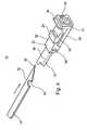
- the structure of the crochet head 41is more particularly illustrated in Figure 3 . It includes a tapered nose 41a at one end for engaging the suture 5 during the forward movement of the crochet head, and a hook formation at the opposite end for receiving the suture and for clamping it to the jaw 23 during the return movement of the crochet head.
- the crochet headis further formed with an axial slot 41c to accommodate the pointed tip 31b of the puncturer 31 when the puncturer is pivoted to its closed position and the crochet has been moved to its most forward position.
- the illustrated suturing instrumentmay be used in the following manner.
- handle 30is pivoted away from handle 20 so as to pivot the puncturer 31 to its open position as shown in Figure 2 , to enable the suture 5 to be loaded thereon by passing the suture through opening 31a of the puncturer.
- Handle 30may then be pivoted towards handle 20 to move the puncturer 31, together with the portion of the suture carried thereby, to the closed position of the puncturer, i.e., through opening 23c of jaw 23.
- Thisenables the distal portion of the instrument to be inserted through the cannula (not shown) of the endoscope.
- handle 30may be pivoted away from handle 20 to return the puncturer to its open position, as shown in Figure 2 , preparatory to its use for suturing tissue.
- handle 40is in the position shown in Figure 1 , such that the crochet head 41 actuated by the handle is in its retracted position on the proximal side of jaw 23.
- the surgeonmay then manipulate the instrument with the puncturer 31 in its open position to locate the puncturer on one side of the tissue to be sutured, and to locate the jaw 23 on the opposite side of the tissue to be sutured.
- the surgeonthen moves handle 30 towards handle 20, which thereby, by virtue of the coupling rod 35, pivots puncturer 31 towards jaw 23 and then through the opening 23c in the jaw, to thereby pierce the tissue and to bring the portion of suture 5 within the needle hole 31a to the opposite side of the jaw.
- handle 40While the puncturer is in its closed position, handle 40 is then pivoted clockwise to move the crochet head 41, coupled to the handle by slide 43, through a forward stroke parallel to the elongated shank 21 from the proximal side of the jaw 23 to the distal side thereof, and then releases handle 40 to permit its spring bias to return the crochet head through a return stroke back to its initial position at the proximal side of the jaw.
- suturing instrument 45illustrates an alternative embodiment of the suturing instrument of the present invention which is referred to hereinunder as suturing instrument 45.
- Suturing instrument 45includes a frame assembly (not shown) which is substantially identical to frame assembly 2 shown in Figure 1 and as such includes a first handle at the proximal end, fixed substantially perpendicularly to an elongated shank; a perpendicular extension at the upper end of the first handle which is formed with a slot for accommodating a coupling element; a second handle pivotally mounted to the upper end of the first handle; a coupling element for coupling the second handle to the tissue grasping elements; a first abutment at the upper end of the first handle serving as a stop for limiting the pivotal movement of the second handle; a second abutment at the upper end of the second handle engagable with the first abutment; a third handle pivotally mounted to the upper end of the first handle, preferably including a piano spring to bias the third handle to the position illustrated in Figure 1 ; and a pin movable within a slot which couples a coupling slide to the upper end of the third handle.
- suturing instrument 45further includes a suturing head 70 which includes a separate tissue grasping mechanism and a piercing mechanism, exemplary configurations of which are further described hereinbelow with reference to Figures 4 and 5 .
- suturing instrument 45The function of suturing instrument 45 is distinguished from the function of the formerly described embodiment.
- the formerly described embodimentincludes a puncturer assembly, shown as puncturer assembly 3 in Figure 1 , which grasps the tissue to be sutured, punctures the tissue and passes the suture through the tissue all in one movement, with a crochet head thereafter simply engaging the suture
- suturing head 70 of the present embodimenthas a tissue grasping mechanism 51 which is designed and configured for grasping a tissue and for positioning a suture on a first side of the tissue grasped thereby.
- Suturing head 70further includes a separate crochet head 61 which is designed and configured for piercing through the tissue from a second side thereof and engaging the suture following piercing, thereafter enabling drawing the suture through the tissue.
- suturing instrument 45includes separate piercing and grasping elements, which enable piercing the tissue and carrying the suture through the tissue following piercing thereof.
- Such a suturing head 70 configurationprovides a significant advantage in that it is capable of suturing tissues with a wide range of thicknesses, as there is no puncturer of a specific length to limit the thickness of the tissue capable of being sutured.
- FIGS 4 and 5illustrate a detailed view of one preferred configuration of suturing head 70, illustrating in detail the construction of tissue grasping mechanism 51, hereinafter referred to as mechanism 51, and crochet head 61.
- Mechanism 51includes a static grasping member, hereinafter referred to as static member 52, and a movable grasping member, hereinafter referred to as movable member 55, both positioned at the distal end of suturing instrument 45.
- Static member 52is disposed rigidly on an elongated shank which is similar to shank 21 illustrated in Figure 1 .
- Movable member 55is pivotally mounted to static member 52 by a pin, hereinafter referred to as pivot pin 56, passing through holes formed in both static member 52 and movable member 55 aligned coaxially.
- the holes in static member 52 and movable member 55are sized such that pivot pin 56 is affixed by friction within the hole through static member 52 but is movable relative to the hole through movable member 55, allowing movable member 55 to rotate thereupon. Accordingly, movable member 55 is pivotally movable relative to static member 52.
- mechanism 51is designed and configured for grasping and holding a tissue to be sutured.
- static member 52 and movable member 55each have a face disposed substantially opposite one another.
- the face of static member 52 which faces movable member 55is formed with a series of parallel grooves therein and is hereinafter referred to as ribbed surface 53.
- Each groove of ribbed surface 53is shaped and angled such that any tissue in contact therewith will be limited, preferably prevented, from moving with respect to static member 52.
- the pivotal movement of movable member 55serves to move the face of movable member 55 both closer to, and farther from, ribbed surface 53.
- the movement of movable member 55is controlled by the movement of the second handle and a coupling rod, which are similar in function to handle 30 and coupling rod 35 described hereinabove with respect to Figure 1 . Accordingly, the pivotal motion of handle (30), transmitted by coupling rod (35), will cause movable member 55 to pivot with respect to static member 52 in a jawlike manner, the closing motion being for grasping the tissue to be sutured, the opening motion being for releasing the tissue.
- Figure 4depicts grasping mechanism 51 in a closed position.
- Figure 5depicts grasping mechanism 51 in an open position.
- Mechanism 51is also designed and configured for positioning a suture on a first side of a tissue to be sutured.
- Figure 6shows a detailed view of the distal end of movable member 55.
- movable member 55has a distal end positioned substantially perpendicular to the face opposite static member 52 in the direction of static member 52.
- This angular end of movable member 55is hereinafter referred to as suture end 57.
- Suture end 57is preferably square or rectangular in shape, although it is appreciated that suture end 57 may be of any shape appropriate for the relevant tissue to be sutured.
- Suture end 57is formed with a groove along its circumference, or a portion of its circumference, hereinafter referred to as suture groove 58.
- Suture groove 58is sized so as to accept an appropriate suturing material. Accordingly, the previously described closing motion of movable member 55 serves to position a suture disposed within suture groove 58 on a (first) side of a tissue grasped by mechanism 51.
- Suture end 57is also formed with an opening therein, hereinafter opening 59, that is sized to allow crochet head 61 to pass therethrough.
- Opening 59is shaped and positioned within suture end 57 such that one of its sides extends toward the circumference of suture end 57 beyond the depth of suture groove 58. Accordingly, at the location that opening 59 approaches the circumference of suture end 57, suture groove 58 is exposed to the inside of opening 59 such that a suture disposed therein is accessible from within opening 59.
- Suturing head 70further includes crochet head 61, designed and configured for piercing through a tissue grasped by mechanism 51, engaging the suture and drawing the suture through the tissue.
- Crochet head 61is part of a crochet head assembly 60 which also includes a third handle and coupling slide (similar to coupling slide 43 shown in Figure 1 ), The movement of coupling slide 43 and crochet head 61 is controlled by the movement of the third handle, which is similar in function to handle 40 described hereinabove with respect to Figure 1 .
- Crochet head 61is formed with a sharp point for piercing a tissue to be sutured, hereinafter referred to as point 62, and a hooklike formation, hereinafter referred to as hook 63, designed to deflect a suture as crochet head 61 first passes the suture when moving in the direction of its extended position and to engage the suture as it subsequently passes the suture moving in a reverse direction toward its retracted position.
- Crochet head 61is carried at the distal end of coupling slide 43.
- Coupling slide 43which includes an element slidable with respect to elongated shank 21, is coupled to the upper end of handle (40).
- Handle (40)is pivotally mounted to the first handle, which is similar in function to handle 20 described hereinabove with respect to Figure 1 .
- Handle (20)is preferably spring biased (spring not shown) to return handle (40) to the position whereby crochet head 61 is in its retracted position. The movement of crochet head 61 is controlled by the movement of handle (40) and coupling slide 43 in substantially the same manner as previously described with reference to Figure 1 .
- crochet head 61moves through forward and return strokes substantially parallel to the longitudinal axis of elongated shank (21).
- Crochet head 61is slidably mounted in proximity to mechanism 51 and is movable through a forward stroke from a retracted position at the proximal end of mechanism 51 to an extended position beyond suture end 57, and through a return stroke back to the retracted position.
- the forward stroke of crochet head 61is for piercing the tissue held by mechanism 51 and the return stroke of crochet head 61 is for engaging the suture and drawing it through the tissue.
- suturing instrument 45is preferably held with the middle finger in the loop of handle (20), the index finger in the loop of handle (40) and the thumb in the loop of handle (30).
- the distal end of suturing instrument 45is passed through a cannula and is placed at the surgical site.
- Handle (30)is pivoted away from handle (20) by the thumb so as to pivot movable member 55 such that grasping mechanism 51 is in its open position, as shown in Figure 5 , to enable grasping mechanism 51 to grasp a tissue to be sutured.
- grasping mechanism 51With grasping mechanism 51 in the open orientation, the instrument is positioned such that a tissue to be sutured is placed within the gap between static member 52 and movable member 55.
- Handle (30)is then pivoted towards handle (20) to pivot movable member 55 toward ribbed surface 53 causing mechanism 51 to move to its closed position (as shown in Figure 4 ) in order to both grasp the tissue and position the suture on the side of the tissue.
- Closing mechanism 51causes opening 59 to align with guide member (24).
- Handle (40)is then pivoted toward handle (20) with the index finger to move crochet head 61 through a forward stroke from its retracted position at the proximal end of mechanism 51 to beyond suture end 57.
- Handle (40)is then released to permit its spring bias to return crochet head 61 through a return stroke back to its retracted position at the proximal end of mechanism 51. If necessary, the index finger in the loop of handle (40) could forcibly pivot handle (40) away from handle (20) causing crochet head 61 to return to its retracted position.
- the suturing instruments of the present inventionoffer a number of substantial advantages over previously described suturing devices.
- the first advantageis simplicity of construction.
- Both embodiments of the suturing instrumentare of simple mechanical design and are fabricated from a relatively small number of moving parts.
- the suturing instruments of the present inventiondo not depend upon excessively close tolerances to function effectively.
- suturing instruments of the present inventionmay be employed with one hand; once the suture is deployed on the device, the tissue may be grasped and the suture completed solely by the movement of the fingers of one hand, leaving the other hand free.
- the suturing instruments of the present inventionprovide a positive and reliable method of effecting a suture from a remote location, thus avoiding missed stitches, a limitation which plagues devices employing separate piercing and retracting elements.
Landscapes
- Health & Medical Sciences (AREA)
- Life Sciences & Earth Sciences (AREA)
- Surgery (AREA)
- Heart & Thoracic Surgery (AREA)
- Engineering & Computer Science (AREA)
- Biomedical Technology (AREA)
- Nuclear Medicine, Radiotherapy & Molecular Imaging (AREA)
- Medical Informatics (AREA)
- Molecular Biology (AREA)
- Animal Behavior & Ethology (AREA)
- General Health & Medical Sciences (AREA)
- Public Health (AREA)
- Veterinary Medicine (AREA)
- Surgical Instruments (AREA)
- Materials For Medical Uses (AREA)
Abstract
Description
- The present invention relates to suturing instruments useful in surgery.
- Many surgical procedures are presently being performed via an endoscope in order to minimize the size of the incisions and the trauma to the patient. In such procedures, the surgical instrument is generally introduced through a cannula or passageways in the endoscope which the surgeon views the surgical site through another passageway in the endoscope, A number of forceps-type suturing instruments are known, such as those described in German Patent
245576 andU.S. Patents 5,730,747 ,6,051,006 ,4,644,953 ,5,522,820 ,2,738,790 , which discloses a tissue suturing instrument according to the preamble of claim 1, and 1,918,700. However these instruments were not designed for introduction through a cannula used in endoscopic procedures, are generally of relatively complicated construction and/or are useful only with respect to needled sutures. - An object of the present invention is to provide a suturing instrument of relatively simple construction and which can be used with unneedled sutures, i,e., suture threadsper se, i,e., without a puncturer being attached to the suture.
- Another object of the invention is to provide a suturing instrument particularly useful as a forceps type instrument for introduction through a cannula used in endoscopic procedures.
- According to the present invention, there is provided a suturing instrument as defined in claim 1.
- According to further features in the described embodiment, the first handle is disposed substantially perpendicular to the elongated shank. Also, the movable member is pivotally mounted to the static member.
- According to further features in the described embodiment, the static member is formed with a face facing the movable member having a ribbed surface for firmly grasping the tissue.
- According to further features in the described embodiment, the static member is formed with a guide member disposed thereon for guiding the crochet head.
- According to further features in the described embodiment, the movable member is for carrying the suture, whereas a distal end of the movable member is formed with an opening therethrough alignable with the guide member for guiding the crochet head to engage the suture when the suture is positioned on the first side of the tissue.
- According to further features in the described embodiment, the tissue grasping mechanism is part of a tissue grasping assembly including a proximal section formed with a second handle pivotally mounted relative to the first handle, a distal section carrying the static member and the movable member, and a coupling between the second handle and the movable member for pivoting the movable member upon pivoting the second handle.
- According to further features in the described embodiment, the coupling includes a rod extending through the elongated shank of the frame assembly.
- According to further features in the described embodiment, the crochet head is part of a crochet head assembly including a proximal section formed with a third handle pivotally mounted relative to the first handle, a distal section carrying the crochet head, and a coupling between the third handle and the crochet head for moving the crochet head upon pivoting the third handle.
- According to further features in the described embodiment, the coupling includes a slide slidable with respect to the elongated shank of the frame assembly, the slide being aligned with the guide member.
- According to further features in the described embodiment, the crochet head is slidably mounted in proximity to the tissue grasping mechanism and is movable through a forward stroke from a retracted position at a proximal end of the tissue grasping mechanism to an extended position beyond a distal end of the tissue grasping mechanism, and through a return stroke back to the retracted position; the crochet head having a point for piercing the tissue during the forward stroke, a shaped surface for engaging the suture, and a hook formation for drawing the suture through the tissue during the return stroke.
- According to further features in the described embodiment, the third handle is spring-biased to the retracted position.
- As will be described more particularly below, the foregoing features enable suturing instruments to be constructed with a relatively few simple parts and to be used with unneedled sutures.
- Further features and advantages of the invention will be apparent from the description below.
- The invention is herein described, by way of example only, with reference to the accompanying drawings. With specific reference now to the drawings in detail, it is stressed that the particulars shown are by way of example and for purposes of illustrative discussion of the preferred embodiments of the present invention only, and are presented in the cause of providing what is believed to be the most useful and readily understood description of the principles and conceptual aspects of the invention. In this regard, no attempt is made to show structural details of the invention in more detail than is necessary for a fundamental understanding of the invention, the description taken with the drawings making apparent to those skilled in the art how the several forms of the invention may be embodied in practice.
- In the drawings:
FIG. 1 is a side view illustrating a preferred embodiment of a suturing instrument not constructed in accordance with the present invention;FIG. 2 is an enlarged bottom view of the distal end of the suturing instrument ofFigure 1 , illustrating the puncturer in its open position for receiving a suture;FIG. 3 is an enlarged side view of the distal end of the suturing instrument ofFigure 1 with the crochet head in its extended position;FIG. 4 is a perspective view of the distal end of an alternative embodiment of a suturing instrument constructed in accordance with the present invention, illustrating the grasping mechanism in its closed position;FIG. 5 is a perspective view of the distal end of the suturing instrument ofFigure 4 illustrating the grasping mechanism in its open position; andFIG. 6 is and end view of the movable grasping member of the suturing instrument ofFigure 4 .- The present invention is of suturing devices which can be used to efficiently insert a suture in tissue during surgery. Specifically, the present invention can be used in minimally invasive, endoscope, laparoscope or arthroscope assisted surgeries.
- The principles and operation of a device according to the present invention may be better understood with reference to the drawings and accompanying descriptions.
- Before explaining the invention in detail, it is to be understood that the invention is not limited in its application to the details of construction and the arrangement of the components set forth in the following descriptions or illustrated in the drawings. The invention is capable of other embodiments or of being practiced or carried out in various ways. Also, it is to be understood that the phraseology and terminology employed herein is for the purpose of description and should not be regarded as limiting.
Figure 1 , illustrates one configuration of a suturing device/instrument not according to the present invention.- The suturing instrument illustrated in
Figure 1 is of the forceps type particularly useful by applying it through a cannula used in endoscopic procedures in order to suture tissue at the surgical site. - This configuration of the suturing instrument is composed of three main assemblies:
- (1) a frame assembly, generally designated2, including a first handle2 at one end (hereinafter called the proximal end), fixed substantially perpendicularly to an elongated shank21 (
Figure 2 ); - (2) a puncturer assembly, generally designated3, including a
second handle 30 at the proximal end of the instrument, pivotally mounted to the frame assembly2 and coupled to a puncturer31 (Figure 2 ) pivotally mounted at the distal end of theelongated shank 21; and - (3) a crochet head assembly, generally designated 4, including a
third handle 40 also pivotally mounted to the frame assembly2 and coupled to aslidable crochet head 41 at the distal end of theelongated shank 21. - As will be described more particularly below, the suture, shown at5 in
Figure 2 , is loaded onto thepuncturer 31 when in its open position as illustrated inFigure 2 . - With respect to the frame assembly2, the proximal end of the
elongated shank 21 is fixed within aperpendicular extension 22 at the upper end ofhandle 20. The distal end of theelongated shank 21 carries afixed jaw 23 formed with a pair oflegs elongated shank 21 and spaced from each other to define aspace 23c. As shown particularly inFigure 2 , the inner surface ofjaw 23 facing thepivotal puncturer 31 is ribbed as shown at23d in order to firmly grasp the tissue to be sutured between it and the pivotal puncturer, as will be described below. - The distal end of the
elongated shank 21 further includes a U-shapedmember 24 serving as a guide for a part of the crochet head assembly4, as will be described below. In addition,extension 22 ofhandle 20 is formed with a slot25 (Fig. 1 ) at the proximal end of theelongated shank 21, for accommodating a coupling element of the crochet head assembly4 as will also be described below. Further, the upper end ofhandle 20 of the frame assembly2 includes anabutment 26 serving as a stop for limiting the pivotal movement ofhandle 30 of the puncturer assembly3. - With respect to the puncturer assembly3, handle30 of that assembly is pivotally mounted at32 to the upper end of
handle 20 of the frame assembly2. As shown particularly inFig 2 ,puncturer 31 pivotally mounted at the distal end of theelongated shank 21, is formed with ahole 31a for receiving thesuture 5, and with apointed tip 31b for piercing the tissue clamped between it and the ribbedsurface 23d of the fixedjaw 23. Puncturer 31 is pivotally mounted to the distal end of theelongated shank 21 by anarm 33 carrying thepuncturer 31 at one end, and pivotally mounted at itsopposite end 34 to theelongated shank 21.Arm 33 is coupled to the upper end ofhandle 30 of the puncturer assembly3 by a rod 35 (Fig. 1 ) passing through, or alongside of, theelongated shank 21. The arrangement is such that pivoting handle30 away fromhandle 20 pivots puncturer31 to its open position illustrated inFigure 2 for receiving thesuture 5, andpivoting handle 30 towardshandle 20moves puncturer 31 through the opening23c in thejaw 23 to pierce the tissue clamped between the puncturer and the jaw, and to bring thesuture 5 to the opposite side of the jaw.Handle 30 is formed on its inner face with anabutment 36 engagable withabutment 26 ofhandle 20 to limit the latter pivotal movement ofhandle 30.- With respect to the crochet head assembly4, its
handle 40 is pivotally mounted at42 to the upper end ofhandle 20 of the frame assembly2. Preferably, this pivotal mounting includes a piano spring (not shown) to bias thehandle 40 to the position illustrated inFigure 1 , which is the retracted position of thecrochet head 41. - The
crochet head 41 is carried at the distal end of aslide 43 extending along one side of theelongated shank 21. The proximal end ofslide 43 is coupled by a pin44 (Fig. 1 ) to the upper end ofhandle 40.Pin 44 is movable withinslot 25 in theextension 22 at the upper end ofhandle 20 to limit the pivotal movements ofhandle 40 with respect to handle20. As will be described below,handle 40 may be pivoted with respect to handle20 to moveslide 43, and thecrochet 41 carried at the distal end of the slide, through forward and return strokes parallel to the longitudinal axis of theelongated shank 21. The forward and return movements of theslide 43 are guided by theU-shaped member 24 at the distal end of the elongated shank. - The structure of the
crochet head 41 is more particularly illustrated inFigure 3 . It includes atapered nose 41a at one end for engaging thesuture 5 during the forward movement of the crochet head, and a hook formation at the opposite end for receiving the suture and for clamping it to thejaw 23 during the return movement of the crochet head. The crochet head is further formed with anaxial slot 41c to accommodate thepointed tip 31b of thepuncturer 31 when the puncturer is pivoted to its closed position and the crochet has been moved to its most forward position. - The illustrated suturing instrument may be used in the following manner.
- First, handle30 is pivoted away from
handle 20 so as to pivot thepuncturer 31 to its open position as shown inFigure 2 , to enable thesuture 5 to be loaded thereon by passing the suture throughopening 31a of the puncturer. Handle 30 may then be pivoted towardshandle 20 to move thepuncturer 31, together with the portion of the suture carried thereby, to the closed position of the puncturer, i.e., through opening23c ofjaw 23. This enables the distal portion of the instrument to be inserted through the cannula (not shown) of the endoscope. After the distal portion of the instrument has passed through the cannula and is located in the surgical site, handle30 may be pivoted away fromhandle 20 to return the puncturer to its open position, as shown inFigure 2 , preparatory to its use for suturing tissue. In this condition of the instrument, handle40 is in the position shown inFigure 1 , such that thecrochet head 41 actuated by the handle is in its retracted position on the proximal side ofjaw 23.- The surgeon may then manipulate the instrument with the
puncturer 31 in its open position to locate the puncturer on one side of the tissue to be sutured, and to locate thejaw 23 on the opposite side of the tissue to be sutured. The surgeon then moves handle30 towardshandle 20, which thereby, by virtue of thecoupling rod 35, pivotspuncturer 31 towardsjaw 23 and then through theopening 23c in the jaw, to thereby pierce the tissue and to bring the portion ofsuture 5 within theneedle hole 31a to the opposite side of the jaw. While the puncturer is in its closed position, handle40 is then pivoted clockwise to move thecrochet head 41, coupled to the handle byslide 43, through a forward stroke parallel to theelongated shank 21 from the proximal side of thejaw 23 to the distal side thereof, and then releases handle40 to permit its spring bias to return the crochet head through a return stroke back to its initial position at the proximal side of the jaw. - During the movement of the crochet head in the forward stroke, its
nose 41a engages the suture that has been passed throughopening 23c injaw 23, and guides the suture to thehook portion 41b of the crochet head, such that when the crochet head returns during the return stroke back to its initial position, thehook portion 41b of the crochet head clamps the suture to thejaw 23.Handle 30 may then be moved away fromhandle 20 to pivot thepuncturer 31 to its open position, and thereby to release the tissue. The instrument may then be used for applying another suture to another portion of the tissue by repeating the foregoing steps. - Reference is now made to
Figures 4-6 which illustrate an alternative embodiment of the suturing instrument of the present invention which is referred to hereinunder as suturing instrument45. - Suturing instrument45 includes a frame assembly (not shown) which is substantially identical to frame assembly2 shown in
Figure 1 and as such includes a first handle at the proximal end, fixed substantially perpendicularly to an elongated shank; a perpendicular extension at the upper end of the first handle which is formed with a slot for accommodating a coupling element; a second handle pivotally mounted to the upper end of the first handle; a coupling element for coupling the second handle to the tissue grasping elements; a first abutment at the upper end of the first handle serving as a stop for limiting the pivotal movement of the second handle; a second abutment at the upper end of the second handle engagable with the first abutment; a third handle pivotally mounted to the upper end of the first handle, preferably including a piano spring to bias the third handle to the position illustrated inFigure 1 ; and a pin movable within a slot which couples a coupling slide to the upper end of the third handle. These components of suturing instrument45 function similarly to those described hereinabove with respect toFigure 1 , and as such are numerically referenced hereinunder, in parentheses, with numbers used to identify similar components shown inFigure 1 . - In addition, suturing instrument45 further includes a
suturing head 70 which includes a separate tissue grasping mechanism and a piercing mechanism, exemplary configurations of which are further described hereinbelow with reference toFigures 4 and5 . - The function of suturing instrument45 is distinguished from the function of the formerly described embodiment. Whereas the formerly described embodiment includes a puncturer assembly, shown as puncturer assembly3 in
Figure 1 , which grasps the tissue to be sutured, punctures the tissue and passes the suture through the tissue all in one movement, with a crochet head thereafter simply engaging the suture, suturinghead 70 of the present embodiment has atissue grasping mechanism 51 which is designed and configured for grasping a tissue and for positioning a suture on a first side of the tissue grasped thereby.Suturing head 70 further includes aseparate crochet head 61 which is designed and configured for piercing through the tissue from a second side thereof and engaging the suture following piercing, thereafter enabling drawing the suture through the tissue. - Thus, in contrast to the formerly described embodiment, suturing instrument45 includes separate piercing and grasping elements, which enable piercing the tissue and carrying the suture through the tissue following piercing thereof.
- Such a
suturing head 70 configuration provides a significant advantage in that it is capable of suturing tissues with a wide range of thicknesses, as there is no puncturer of a specific length to limit the thickness of the tissue capable of being sutured. Figures 4 and5 illustrate a detailed view of one preferred configuration of suturinghead 70, illustrating in detail the construction oftissue grasping mechanism 51, hereinafter referred to asmechanism 51, andcrochet head 61.Mechanism 51 includes a static grasping member, hereinafter referred to asstatic member 52, and a movable grasping member, hereinafter referred to asmovable member 55, both positioned at the distal end of suturing instrument45.Static member 52 is disposed rigidly on an elongated shank which is similar toshank 21 illustrated inFigure 1 .Movable member 55 is pivotally mounted tostatic member 52 by a pin, hereinafter referred to aspivot pin 56, passing through holes formed in bothstatic member 52 andmovable member 55 aligned coaxially. The holes instatic member 52 andmovable member 55 are sized such thatpivot pin 56 is affixed by friction within the hole throughstatic member 52 but is movable relative to the hole throughmovable member 55, allowingmovable member 55 to rotate thereupon. Accordingly,movable member 55 is pivotally movable relative tostatic member 52.- As described above,
mechanism 51 is designed and configured for grasping and holding a tissue to be sutured. Accordingly,static member 52 andmovable member 55 each have a face disposed substantially opposite one another. The face ofstatic member 52 which facesmovable member 55 is formed with a series of parallel grooves therein and is hereinafter referred to as ribbedsurface 53. Each groove of ribbedsurface 53 is shaped and angled such that any tissue in contact therewith will be limited, preferably prevented, from moving with respect tostatic member 52. - The pivotal movement of
movable member 55 serves to move the face ofmovable member 55 both closer to, and farther from, ribbedsurface 53. The movement ofmovable member 55 is controlled by the movement of the second handle and a coupling rod, which are similar in function to handle30 andcoupling rod 35 described hereinabove with respect toFigure 1 . Accordingly, the pivotal motion of handle(30), transmitted by coupling rod(35), will causemovable member 55 to pivot with respect tostatic member 52 in a jawlike manner, the closing motion being for grasping the tissue to be sutured, the opening motion being for releasing the tissue.Figure 4 depicts graspingmechanism 51 in a closed position.Figure 5 depicts graspingmechanism 51 in an open position. Mechanism 51 is also designed and configured for positioning a suture on a first side of a tissue to be sutured. Reference is now made toFigure 6 which shows a detailed view of the distal end ofmovable member 55. According to the alternative embodiment,movable member 55 has a distal end positioned substantially perpendicular to the face oppositestatic member 52 in the direction ofstatic member 52. This angular end ofmovable member 55 is hereinafter referred to assuture end 57.Suture end 57 is preferably square or rectangular in shape, although it is appreciated thatsuture end 57 may be of any shape appropriate for the relevant tissue to be sutured.Suture end 57 is formed with a groove along its circumference, or a portion of its circumference, hereinafter referred to assuture groove 58.Suture groove 58 is sized so as to accept an appropriate suturing material. Accordingly, the previously described closing motion ofmovable member 55 serves to position a suture disposed withinsuture groove 58 on a (first) side of a tissue grasped bymechanism 51.Suture end 57 is also formed with an opening therein, hereinafter opening59, that is sized to allowcrochet head 61 to pass therethrough.Opening 59 is shaped and positioned withinsuture end 57 such that one of its sides extends toward the circumference ofsuture end 57 beyond the depth ofsuture groove 58. Accordingly, at the location that opening59 approaches the circumference ofsuture end 57,suture groove 58 is exposed to the inside of opening59 such that a suture disposed therein is accessible from withinopening 59.Suturing head 70 further includescrochet head 61, designed and configured for piercing through a tissue grasped bymechanism 51, engaging the suture and drawing the suture through the tissue.Crochet head 61 is part of a crochet head assembly60 which also includes a third handle and coupling slide (similar tocoupling slide 43 shown inFigure 1 ), The movement ofcoupling slide 43 andcrochet head 61 is controlled by the movement of the third handle, which is similar in function to handle40 described hereinabove with respect toFigure 1 .Crochet head 61 is formed with a sharp point for piercing a tissue to be sutured, hereinafter referred to aspoint 62, and a hooklike formation, hereinafter referred to ashook 63, designed to deflect a suture ascrochet head 61 first passes the suture when moving in the direction of its extended position and to engage the suture as it subsequently passes the suture moving in a reverse direction toward its retracted position.Crochet head 61 is carried at the distal end ofcoupling slide 43. Couplingslide 43, which includes an element slidable with respect to elongatedshank 21, is coupled to the upper end of handle(40). Handle(40) is pivotally mounted to the first handle, which is similar in function to handle20 described hereinabove with respect toFigure 1 . Handle(20) is preferably spring biased (spring not shown) to return handle(40) to the position wherebycrochet head 61 is in its retracted position. The movement ofcrochet head 61 is controlled by the movement of handle(40) andcoupling slide 43 in substantially the same manner as previously described with reference toFigure 1 .- Accordingly, the pivotal motion of handle(40) with respect to handle(20) will cause
crochet head 61 to move through forward and return strokes substantially parallel to the longitudinal axis of elongated shank(21).Crochet head 61 is slidably mounted in proximity tomechanism 51 and is movable through a forward stroke from a retracted position at the proximal end ofmechanism 51 to an extended position beyondsuture end 57, and through a return stroke back to the retracted position. The forward stroke ofcrochet head 61 is for piercing the tissue held bymechanism 51 and the return stroke ofcrochet head 61 is for engaging the suture and drawing it through the tissue. - The forward and return movements of
crochet head 61 are guided by an inverted U-shaped guide member (similar tomember 24 ofFigure 1 ) which is formed as part ofstatic member 52.Guide member 24 guides point62 to pass within opening59 at a point where opening59 approaches the circumference ofsuture end 57 beyond the depth ofsuture groove 58 such thatcrochet head 61 passes between the circumference ofopening 59 and a suture disposed withinsuture groove 58. As described above, the deployment of handles(20, 30 and40) proximal to one another allows suturing instrument45 to be easily employed by a user. Once the suture is disposed onsuture head 70, a user may preferably operate each of the handles in proper sequence by the fingers of one hand, as follows. - First, a suture is disposed within
suture groove 58. Thereafter, suturing instrument45 is preferably held with the middle finger in the loop of handle(20), the index finger in the loop of handle(40) and the thumb in the loop of handle(30). The distal end of suturing instrument45 is passed through a cannula and is placed at the surgical site. Handle(30) is pivoted away from handle(20) by the thumb so as to pivotmovable member 55 such that graspingmechanism 51 is in its open position, as shown inFigure 5 , to enable graspingmechanism 51 to grasp a tissue to be sutured. With graspingmechanism 51 in the open orientation, the instrument is positioned such that a tissue to be sutured is placed within the gap betweenstatic member 52 andmovable member 55. - Handle(30) is then pivoted towards handle(20) to pivot
movable member 55 toward ribbedsurface 53 causingmechanism 51 to move to its closed position (as shown inFigure 4 ) in order to both grasp the tissue and position the suture on the side of the tissue.Closing mechanism 51 causes opening59 to align with guide member(24). Handle(40) is then pivoted toward handle(20) with the index finger to movecrochet head 61 through a forward stroke from its retracted position at the proximal end ofmechanism 51 to beyondsuture end 57. Handle(40) is then released to permit its spring bias to returncrochet head 61 through a return stroke back to its retracted position at the proximal end ofmechanism 51. If necessary, the index finger in the loop of handle(40) could forcibly pivot handle(40) away from handle(20) causingcrochet head 61 to return to its retracted position. - During the movement of
crochet head 61 in the forward stroke,point 62 pierces and penetrates through the tissue grasped and thereafter passes between the suture withinsuture groove 58 and the circumference ofopening 59.Crochet head 61 is thus moved sufficiently past the suture such thathook 63 engages the suture on the return stroke and draws it through the hole pierced through the tissue. Handle(30) is then pivoted away from handle(20) by the thumb to movemechanism 51 to its open position, and thereby to release the tissue. Thereafter, suturing instrument45 may then be withdrawn from the cannula, drawing the suture with it. - The suturing instruments of the present invention offer a number of substantial advantages over previously described suturing devices. The first advantage is simplicity of construction. Both embodiments of the suturing instrument are of simple mechanical design and are fabricated from a relatively small number of moving parts. In addition, the suturing instruments of the present invention do not depend upon excessively close tolerances to function effectively.
- Furthermore, the suturing instruments of the present invention may be employed with one hand; once the suture is deployed on the device, the tissue may be grasped and the suture completed solely by the movement of the fingers of one hand, leaving the other hand free.
- Finally, the suturing instruments of the present invention provide a positive and reliable method of effecting a suture from a remote location, thus avoiding missed stitches, a limitation which plagues devices employing separate piercing and retracting elements.
- It is appreciated that certain features of the invention, which are, for clarity, described in the context of separate embodiments, may also be provided in combination in a single embodiment. Conversely, various features of the invention, which are, for brevity, described in the context of a single embodiment, may also be provided separately or in any suitable subcombination.
Claims (12)
- A tissue suturing instrument comprising:a tissue grasping mechanism (24, 25) designed and configured for grasping a tissue and for positioning a suture on a first side of said tissue grasped thereby; anda crochet head (61) designed and configured for piercing through said tissue from a second side thereof and engaging said suture following said piercing, thereby enabling drawing of said suture through said tissue;
whereinthe instrument further comprises a frame assembly (2) including a proximal section (22) formed with a first handle (20) and a distal section (23) carrying said tissue grasping mechanism (24, 25) and said crochet head (61), said proximal section (22) and said distal section (23) being connected by an elongated shank (21);said tissue grasping mechanism (24, 25) comprises at least two grasping members (24, 55) including a static member (52) disposed rigidly upon said elongated shank (21) and a movable member (55) movable relative to said static member (52);and said crochet head (61) is slidably carried by said static grasping member (52) and is slidable in a rectilinear path parallel to said static grasping member (52) through a forward stroke from a retracted position at the proximal end of the static grasping member to an extended position at the distal end of the static grasping member and through, a return stroke back to the retracted position,characterized in that: said movable member is pivotally movable relative to said static member. - The instrument of claim 1, wherein said first handle (20) is disposed substantially perpendicular to said elongated shank (21).
- The instrument of claim 1, wherein said movable member (55) is pivotally mounted to said static member (51).
- The instrument of claim 1, wherein the static member (24) is formed with a face having a ribbed surface (53) for firmly grasping said tissue, said face facing the movable member (55).
- The instrument of claim 1, wherein said static member (24) is formed with a guide member (24) disposed thereon for guiding said crochet head (61).
- The instrument of claim 5, wherein said movable member (55) is for carrying said suture, whereas a distal end of said movable member (55) is formed with an opening therethrough alignable with said guide member (24) for guiding said crochet head (61) to engage said suture when said suture is positioned on said first side of said tissue.
- The instrument of claim 1, wherein said tissue grasping mechanism (24, 25) is part of a tissue grasping assembly including a proximal section formed with a second handle (30) pivotally mounted relative to said first handle (20), a distal section carrying Received the said static member (52) and said movable member (55), and a coupling (43) between said
second handle (30) and said movable member (55) for pivoting said movable member (55) upon pivoting said second handle (30). - The instrument of claim 7, wherein said coupling (43) includes a rod (43) extending through said elongated shank (21) of the frame assembly (2),
- The instrument of claim 1, wherein said crochet head (61) is part of a crochet head assembly (60) including a proximal section formed with a third handle (40) pivotally mounted relative to said first handle (20), a distal section carrying said crochet head (61), and a coupling (43) between said third handle (40) and said crochet head (61) for moving said crochet head (61) upon pivoting said third handle (40).
- The instrument of claims 5 and 9, wherein said coupling (43) includes a slide (43) slidable with respect to said elongated shank (21) of the frame assembly (2), said slide (43) being aligned with said guide member (24).
- The instrument of claim 10, wherein said crochet head (61) is slidably mounted in proximity to said tissue grasping mechanism (24, 25) and is movable through a forward stroke from a retracted position at a proximal end of the tissue grasping mechanism (24, 25) to an extended position beyond a distal end of said tissue grasping mechanism (24, 25), and through a return stroke back to said retracted position; said crochet head (61) having a point (62) for piercing the tissue during the forward stroke, a shaped surface for engaging the suture, and a hook formation (63) for drawing said suture through said tissue during the return stroke.
- The instrument of claim 11, wherein said third handle (40) is spring-biased to said retracted position.
Applications Claiming Priority (3)
| Application Number | Priority Date | Filing Date | Title |
|---|---|---|---|
| US09/722,712US6511487B1 (en) | 2000-11-28 | 2000-11-28 | Suturing instrument and method |
| US722712 | 2000-11-28 | ||
| PCT/IL2001/001094WO2002043558A2 (en) | 2000-11-28 | 2001-11-28 | Suturing instrument and method |
Publications (3)
| Publication Number | Publication Date |
|---|---|
| EP1337190A2 EP1337190A2 (en) | 2003-08-27 |
| EP1337190A4 EP1337190A4 (en) | 2009-04-01 |
| EP1337190B1true EP1337190B1 (en) | 2011-06-08 |
Family
ID=24903057
Family Applications (1)
| Application Number | Title | Priority Date | Filing Date |
|---|---|---|---|
| EP01998258AExpired - LifetimeEP1337190B1 (en) | 2000-11-28 | 2001-11-28 | Suturing instrument and method |
Country Status (7)
| Country | Link |
|---|---|
| US (3) | US6511487B1 (en) |
| EP (1) | EP1337190B1 (en) |
| AT (1) | ATE511801T1 (en) |
| AU (1) | AU2002221007A1 (en) |
| ES (1) | ES2367780T3 (en) |
| IL (1) | IL156014A0 (en) |
| WO (1) | WO2002043558A2 (en) |
Families Citing this family (81)
| Publication number | Priority date | Publication date | Assignee | Title |
|---|---|---|---|---|
| WO1997039135A1 (en)* | 1996-04-17 | 1997-10-23 | Board Of Regents, The University Of Texas System | Enhanced expression of transgenes |
| US6511487B1 (en)* | 2000-11-28 | 2003-01-28 | T. A. G. Medical Products Ltd. | Suturing instrument and method |
| ATE415869T1 (en)* | 2001-03-23 | 2008-12-15 | Arthrex Inc | INSTRUMENT FOR PULLING A THREAD DURING ARTHROSCOPIC SEWING OF TISSUE |
| US7879046B2 (en)* | 2001-10-01 | 2011-02-01 | Depuy Mitek, Inc. | Suturing apparatus and method |
| US6984237B2 (en) | 2002-05-22 | 2006-01-10 | Orthopaedic Biosystems Ltd., Inc. | Suture passing surgical instrument |
| US8333774B2 (en)* | 2003-10-23 | 2012-12-18 | Arthrex, Inc. | Suturing instrument with needle dock |
| JP4482640B2 (en)* | 2003-10-28 | 2010-06-16 | 学校法人日本大学 | Suture transfer device |
| EP1755461B1 (en)* | 2004-06-16 | 2014-01-01 | Smith & Nephew, Inc. | Suture passing device |
| US7883519B2 (en)* | 2004-07-06 | 2011-02-08 | Ran Oren | Suture manipulating instrument particularly useful with endoscopes |
| ATE477749T1 (en)* | 2006-03-17 | 2010-09-15 | T A G Medical Products A Ltd P | SURGICAL INSTRUMENT FOR ATTACHING SOFT TISSUE TO BONE |
| AU2007280012B2 (en) | 2006-07-31 | 2013-01-31 | T.A.G. Medical Devices - Agriculture Cooperative Ltd. | Arthroscopic bone transplanting procedure, and medical instruments useful therein |
| JP5481194B2 (en) | 2006-10-05 | 2014-04-23 | コヴィディエン リミテッド パートナーシップ | Flexible endoscopic suturing device |
| US8226667B2 (en) | 2006-10-05 | 2012-07-24 | Tyco Healthcare Group Lp | Axial stitching device |
| US20080154300A1 (en)* | 2006-12-15 | 2008-06-26 | Noel Jabbour | Surgical forceps |
| EP2157924B1 (en)* | 2007-05-30 | 2019-11-06 | T.A.G. Medical Devices - Agriculture Cooperative Ltd. | Piercing implement particularly useful as a medical implement for piercing body tissue |
| US20110130773A1 (en)* | 2007-07-03 | 2011-06-02 | Saliman Justin D | Methods for continuous suture passing |
| US20090012538A1 (en)* | 2007-07-03 | 2009-01-08 | Justin Saliman | Methods and devices for continuous suture passing |
| US20100130990A1 (en)* | 2007-07-03 | 2010-05-27 | Saliman Justin D | Methods of suturing and repairing tissue using a continuous suture passer device |
| US8663253B2 (en) | 2007-07-03 | 2014-03-04 | Ceterix Orthopaedics, Inc. | Methods of meniscus repair |
| US8702731B2 (en) | 2007-07-03 | 2014-04-22 | Ceterix Orthopaedics, Inc. | Suturing and repairing tissue using in vivo suture loading |
| US9861354B2 (en) | 2011-05-06 | 2018-01-09 | Ceterix Orthopaedics, Inc. | Meniscus repair |
| US8911456B2 (en) | 2007-07-03 | 2014-12-16 | Ceterix Orthopaedics, Inc. | Methods and devices for preventing tissue bridging while suturing |
| US8465505B2 (en) | 2011-05-06 | 2013-06-18 | Ceterix Orthopaedics, Inc. | Suture passer devices and methods |
| US10441273B2 (en) | 2007-07-03 | 2019-10-15 | Ceterix Orthopaedics, Inc. | Pre-tied surgical knots for use with suture passers |
| US9314234B2 (en) | 2007-07-03 | 2016-04-19 | Ceterix Orthopaedics, Inc. | Pre-tied surgical knots for use with suture passers |
| US8821518B2 (en)* | 2007-11-05 | 2014-09-02 | Ceterix Orthopaedics, Inc. | Suture passing instrument and method |
| US8500809B2 (en) | 2011-01-10 | 2013-08-06 | Ceterix Orthopaedics, Inc. | Implant and method for repair of the anterior cruciate ligament |
| US9211119B2 (en) | 2007-07-03 | 2015-12-15 | Ceterix Orthopaedics, Inc. | Suture passers and methods of passing suture |
| EP2033583B1 (en) | 2007-08-27 | 2013-03-13 | Arthrex, Inc. | In-line suture passer |
| US8864776B2 (en)* | 2008-04-11 | 2014-10-21 | Covidien Lp | Deployment system for surgical suture |
| US20110040308A1 (en) | 2008-06-13 | 2011-02-17 | Ramiro Cabrera | Endoscopic Stitching Devices |
| US8628545B2 (en)* | 2008-06-13 | 2014-01-14 | Covidien Lp | Endoscopic stitching devices |
| AU2010228986B2 (en)* | 2009-03-23 | 2015-03-26 | Linvatec Corporation | Suture passing apparatus and method |
| USD708746S1 (en) | 2009-06-10 | 2014-07-08 | Covidien Lp | Handle for surgical device |
| US9198655B2 (en) | 2009-07-15 | 2015-12-01 | Pivot Medical, Inc. | Method and apparatus for treating a hip joint, including the provision and use of a novel suture passer |
| US8490713B2 (en) | 2009-10-06 | 2013-07-23 | Covidien Lp | Handle assembly for endoscopic suturing device |
| US9848868B2 (en) | 2011-01-10 | 2017-12-26 | Ceterix Orthopaedics, Inc. | Suture methods for forming locking loops stitches |
| US11744575B2 (en) | 2009-11-09 | 2023-09-05 | Ceterix Orthopaedics, Inc. | Suture passer devices and methods |
| US9011454B2 (en) | 2009-11-09 | 2015-04-21 | Ceterix Orthopaedics, Inc. | Suture passer with radiused upper jaw |
| JP5719374B2 (en) | 2009-11-09 | 2015-05-20 | セテリックス オーソピーディクス インコーポレイテッド | Device, system, and method for repairing a meniscus |
| US9913638B2 (en) | 2011-01-10 | 2018-03-13 | Ceterix Orthopaedics, Inc. | Transosteal anchoring methods for tissue repair |
| US8864777B2 (en) | 2011-01-28 | 2014-10-21 | Anchor Orthopedics Xt Inc. | Methods for facilitating tissue puncture |
| US8556916B2 (en) | 2011-02-14 | 2013-10-15 | Smith & Nephew, Inc. | Method and device for suture manipulation |
| US8968340B2 (en) | 2011-02-23 | 2015-03-03 | Covidien Lp | Single actuating jaw flexible endolumenal stitching device |
| US8882834B2 (en) | 2011-07-08 | 2014-11-11 | Smith & Nephew, Inc. | Soft tissue repair |
| US8951263B2 (en) | 2011-07-08 | 2015-02-10 | Smith & Nephew, Inc. | Orthopedic suture passer and method |
| US8888849B2 (en) | 2011-07-08 | 2014-11-18 | Smith & Nephew, Inc. | Soft tissue repair |
| US9662105B2 (en) | 2011-07-08 | 2017-05-30 | Smith & Nephew, Inc. | Suture passer and method |
| US9357997B2 (en) | 2011-07-08 | 2016-06-07 | Smith & Nephew, Inc. | Suture passer and method |
| US8801727B2 (en) | 2011-07-08 | 2014-08-12 | Smith & Nephew, Inc. | Orthopedic suture passer and method |
| US10524778B2 (en) | 2011-09-28 | 2020-01-07 | Ceterix Orthopaedics | Suture passers adapted for use in constrained regions |
| US9492162B2 (en) | 2013-12-16 | 2016-11-15 | Ceterix Orthopaedics, Inc. | Automatically reloading suture passer devices and methods |
| US20130123809A1 (en) | 2011-11-11 | 2013-05-16 | VentureMD Innovations, LLC | Transosseous attachment instruments |
| US10675014B2 (en) | 2011-11-16 | 2020-06-09 | Crossroads Extremity Systems, Llc | Knotless soft tissue attachment |
| US10470756B2 (en) | 2011-11-16 | 2019-11-12 | VentureMD Innovations, LLC | Suture anchor and method |
| US10136883B2 (en) | 2011-11-16 | 2018-11-27 | VentureMD Innovations, LLC | Method of anchoring a suture |
| US10548585B2 (en) | 2011-11-16 | 2020-02-04 | VentureMD Innovations, LLC | Soft tissue attachment |
| US9687221B2 (en) | 2013-02-13 | 2017-06-27 | Venture MD Innovations, LLC | Method of anchoring a suture |
| US9247935B2 (en) | 2013-09-23 | 2016-02-02 | Ceterix Orthopaedics, Inc. | Arthroscopic knot pusher and suture cutter |
| CN204951031U (en) | 2014-04-08 | 2016-01-13 | 赛特里克斯整形公司 | Ware device is worn to draw by suture |
| CN106456155A (en) | 2014-04-24 | 2017-02-22 | 史密夫和内修有限公司 | Suture passer |
| US9468434B2 (en) | 2014-06-03 | 2016-10-18 | Covidien Lp | Stitching end effector |
| US9936943B1 (en) | 2014-08-07 | 2018-04-10 | Nicholas MANCINI | Suture passing surgical device with atraumatic grasper preventing accidental perforations |
| US10092286B2 (en) | 2015-05-27 | 2018-10-09 | Covidien Lp | Suturing loading unit |
| US10258401B2 (en) | 2015-07-17 | 2019-04-16 | Kator, Llc | Transosseous guide |
| US10820918B2 (en) | 2015-07-17 | 2020-11-03 | Crossroads Extremity Systems, Llc | Transosseous guide and method |
| US9962174B2 (en) | 2015-07-17 | 2018-05-08 | Kator, Llc | Transosseous method |
| US10226245B2 (en) | 2015-07-21 | 2019-03-12 | Ceterix Orthopaedics, Inc. | Automatically reloading suture passer devices that prevent entanglement |
| US10226243B2 (en) | 2015-08-04 | 2019-03-12 | Kator, Llc | Transosseous suture anchor |
| US12383253B2 (en) | 2015-08-04 | 2025-08-12 | Crossroads Extremity Systems, Llc | Suture anchor |
| US10080562B2 (en) | 2015-08-06 | 2018-09-25 | DePuy Synthes Products, Inc. | Methods, systems, and devices for surgical suturing |
| US10405853B2 (en) | 2015-10-02 | 2019-09-10 | Ceterix Orthpaedics, Inc. | Knot tying accessory |
| US9439647B1 (en) | 2016-03-02 | 2016-09-13 | Arthrogenx, LLC. | Suture passing instruments and methods |
| US10542970B2 (en) | 2016-05-31 | 2020-01-28 | Covidien Lp | Endoscopic stitching device |
| WO2018081374A1 (en) | 2016-10-31 | 2018-05-03 | Smith & Nephew, Inc. | Suture passer and grasper instrument and method |
| US11197665B2 (en) | 2018-08-06 | 2021-12-14 | Covidien Lp | Needle reload device for use with endostitch device |
| CN111388037B (en)* | 2020-04-03 | 2025-04-11 | 温州医科大学附属第二医院、温州医科大学附属育英儿童医院 | Carpal Surgery Suture Device |
| US11369398B2 (en) | 2020-08-19 | 2022-06-28 | Tag Dream Medical Ltd. | Hybrid laser cutter |
| WO2022182567A1 (en) | 2021-02-25 | 2022-09-01 | Stryker Corporation | Devices and methods for passing and retrieving suture through tissue |
| WO2023038604A1 (en) | 2021-09-07 | 2023-03-16 | Soranus Arge Ve Danismanlik Hizmetleri Sanayi Ticaret Anonim Sirketi | Suturing device and methods of use thereof |
| CN118680616B (en)* | 2024-08-27 | 2024-10-29 | 北京软体机器人科技股份有限公司 | Multi-head clamping device |
Family Cites Families (51)
| Publication number | Priority date | Publication date | Assignee | Title |
|---|---|---|---|---|
| DE245576C (en)* | ||||
| US1822330A (en)* | 1930-01-13 | 1931-09-08 | Ainslie George | Suturing instrument |
| US1815725A (en) | 1930-02-03 | 1931-07-21 | George P Pilling & Son Company | Suture forceps |
| US1856721A (en) | 1931-02-07 | 1932-05-03 | Clemens B Nagelmann | Suturing and ligating instrument |
| US1918700A (en)* | 1931-08-28 | 1933-07-18 | Hyman H Harris | Surgical instrument |
| US1933024A (en)* | 1931-10-06 | 1933-10-31 | Clemens B Nagelmann | Suturing and ligating instrument |
| US2269963A (en) | 1940-06-01 | 1942-01-13 | Wappler Frederick Charles | Implanting device |
| US2577240A (en) | 1949-10-01 | 1951-12-04 | Robert L Findley | Suture hemostat |
| US2738790A (en)* | 1954-08-12 | 1956-03-20 | George P Pilling & Son Company | Suturing instrument |
| US3842840A (en) | 1973-05-07 | 1974-10-22 | E Schweizer | Suture applicator |
| US3946740A (en) | 1974-10-15 | 1976-03-30 | Bassett John W | Suturing device |
| US4109658A (en) | 1977-02-04 | 1978-08-29 | Hughes Joe L | Needle holding device with pick-up means |
| US4164225A (en) | 1977-12-28 | 1979-08-14 | Johnson & Lorenz, Inc. | Surgical suturing instrument |
| US4345601A (en) | 1980-04-07 | 1982-08-24 | Mamoru Fukuda | Continuous suturing device |
| US4741330A (en) | 1983-05-19 | 1988-05-03 | Hayhurst John O | Method and apparatus for anchoring and manipulating cartilage |
| US4493323A (en) | 1982-12-13 | 1985-01-15 | University Of Iowa Research Foundation | Suturing device and method for using same |
| CH662263A5 (en)* | 1983-09-13 | 1987-09-30 | Gegauf Fritz Ag | HYSTERECTOMIUM. |
| US4621640A (en) | 1984-01-09 | 1986-11-11 | Mulhollan James S | Mechanical needle carrier and method for its use |
| US4635637A (en) | 1984-03-29 | 1987-01-13 | Schreiber Saul N | Surgical suture |
| US4738255A (en) | 1986-04-07 | 1988-04-19 | Biotron Labs, Inc. | Suture anchor system |
| US4898156A (en) | 1987-05-18 | 1990-02-06 | Mitek Surgical Products, Inc. | Suture anchor |
| US4890615B1 (en) | 1987-11-05 | 1993-11-16 | Linvatec Corporation | Arthroscopic suturing instrument |
| US4926860A (en) | 1988-02-05 | 1990-05-22 | Flexmedics Corporation | ARthroscopic instrumentation and method |
| US4836205A (en) | 1988-03-21 | 1989-06-06 | Barrett Gene R | Grasper-stitcher device for arthroscopic anterior cruciate ligament repair |
| US4935027A (en) | 1989-08-21 | 1990-06-19 | Inbae Yoon | Surgical suture instrument with remotely controllable suture material advancement |
| GB2236168B (en)* | 1989-09-21 | 1993-04-07 | Torrington Co | Vehicle steering column |
| US5059201A (en)* | 1989-11-03 | 1991-10-22 | Asnis Stanley E | Suture threading, stitching and wrapping device for use in open and closed surgical procedures |
| US5037422A (en) | 1990-07-02 | 1991-08-06 | Acufex Microsurgical, Inc. | Bone anchor and method of anchoring a suture to a bone |
| US5085661A (en) | 1990-10-29 | 1992-02-04 | Gerald Moss | Surgical fastener implantation device |
| GB2260704B (en) | 1991-09-30 | 1995-08-23 | Philip Richardson | Suturing apparatus |
| US5342389A (en) | 1992-04-28 | 1994-08-30 | Habley Medical Technology Corporation | Tissue manipulator |
| US5304184A (en) | 1992-10-19 | 1994-04-19 | Indiana University Foundation | Apparatus and method for positive closure of an internal tissue membrane opening |
| DE69315808T2 (en) | 1992-11-17 | 1998-04-09 | Smith & Nephew Inc | Device for fastening sutures |
| US5417699A (en) | 1992-12-10 | 1995-05-23 | Perclose Incorporated | Device and method for the percutaneous suturing of a vascular puncture site |
| US5522820A (en)* | 1993-01-15 | 1996-06-04 | Arthrotech | Method and apparatus for suturing tissue |
| US5609597A (en) | 1993-12-09 | 1997-03-11 | Lehrer; Theodor | Apparatus and method of extracorporeally applying and locking laparoscopic suture and loop ligatures |
| US5466243A (en) | 1994-02-17 | 1995-11-14 | Arthrex, Inc. | Method and apparatus for installing a suture anchor through a hollow cannulated grasper |
| US5645552A (en) | 1995-01-11 | 1997-07-08 | United States Surgical Corporation | Surgical apparatus for suturing body tissue |
| US5730747A (en) | 1995-06-07 | 1998-03-24 | Smith & Nephew, Inc. | Suture passing forceps |
| US6129741A (en) | 1995-06-10 | 2000-10-10 | Forschungszentrum Karlsruhe Gmbh | Surgical suturing needle |
| US5776150A (en) | 1996-06-10 | 1998-07-07 | Ethicon Endo Surgery, Inc. | Suture assist device |
| US5665108A (en) | 1996-09-16 | 1997-09-09 | Galindo; Eugene R. | Surgical dressing strap |
| US5843099A (en)* | 1997-01-16 | 1998-12-01 | Bei Medical Systems, Inc. | Single system ligature carrier and tissue clamp for sacrospinous colpopexy |
| AT408832B (en)* | 1997-09-09 | 2002-03-25 | Werner Ing Fuchs | SURGICAL SEWING PLIERS |
| IT1300004B1 (en) | 1998-05-05 | 2000-04-04 | Mario Ciucani | METHOD AND EQUIPMENT FOR SEWING THE UPPER TO THE SOLE OF FOOTWEAR. |
| US6071289A (en) | 1999-03-15 | 2000-06-06 | Ethicon Endo-Surgery, Inc. | Surgical device for suturing tissue |
| US6051006A (en) | 1999-04-12 | 2000-04-18 | Smith & Nephew, Inc. | Suture-passing forceps |
| US6551330B1 (en)* | 2000-09-21 | 2003-04-22 | Opus Medical, Inc. | Linear suturing apparatus and methods |
| US6511487B1 (en) | 2000-11-28 | 2003-01-28 | T. A. G. Medical Products Ltd. | Suturing instrument and method |
| US6770084B1 (en)* | 2002-06-26 | 2004-08-03 | Opus Medical, Inc. | Suture capture device |
| JP4373146B2 (en) | 2002-07-11 | 2009-11-25 | オリンパス株式会社 | Endoscopic suturing device |
- 2000
- 2000-11-28USUS09/722,712patent/US6511487B1/ennot_activeExpired - Lifetime
- 2001
- 2001-11-28ATAT01998258Tpatent/ATE511801T1/ennot_activeIP Right Cessation
- 2001-11-28USUS09/994,882patent/US20020065526A1/ennot_activeAbandoned
- 2001-11-28EPEP01998258Apatent/EP1337190B1/ennot_activeExpired - Lifetime
- 2001-11-28ESES01998258Tpatent/ES2367780T3/ennot_activeExpired - Lifetime
- 2001-11-28ILIL15601401Apatent/IL156014A0/enunknown
- 2001-11-28AUAU2002221007Apatent/AU2002221007A1/ennot_activeAbandoned
- 2001-11-28WOPCT/IL2001/001094patent/WO2002043558A2/ennot_activeApplication Discontinuation
- 2004
- 2004-09-23USUS10/947,139patent/US7608084B2/ennot_activeExpired - Fee Related
Also Published As
| Publication number | Publication date |
|---|---|
| US20020065526A1 (en) | 2002-05-30 |
| US7608084B2 (en) | 2009-10-27 |
| AU2002221007A1 (en) | 2002-06-11 |
| WO2002043558A2 (en) | 2002-06-06 |
| IL156014A0 (en) | 2003-12-23 |
| EP1337190A4 (en) | 2009-04-01 |
| WO2002043558A3 (en) | 2002-10-10 |
| US6511487B1 (en) | 2003-01-28 |
| EP1337190A2 (en) | 2003-08-27 |
| ES2367780T3 (en) | 2011-11-08 |
| ATE511801T1 (en) | 2011-06-15 |
| US20050043748A1 (en) | 2005-02-24 |
Similar Documents
| Publication | Publication Date | Title |
|---|---|---|
| EP1337190B1 (en) | Suturing instrument and method | |
| EP0705568B1 (en) | Vascular suturing apparatus | |
| EP1304081B1 (en) | Endoscopic vascular suturing apparatus | |
| US5522820A (en) | Method and apparatus for suturing tissue | |
| US5827299A (en) | Insertable suture passing grasping probe and methodology for using same | |
| EP1720457B1 (en) | Suture manipulating and cutting implement | |
| US5871488A (en) | Surgical suturing apparatus with locking mechanisms | |
| US6086601A (en) | Instrument and method for suturing anatomical tissue and tying suture material | |
| US7320693B2 (en) | Methods and instruments for closing laparoscopic trocar puncture wounds | |
| US6517552B1 (en) | Suture retriever | |
| US7572265B2 (en) | Method and apparatus for passing a suture | |
| US20030233106A1 (en) | Suture passing instrument | |
| US6159224A (en) | Multiple needle suturing instrument and method | |
| US6074403A (en) | Suture retriever | |
| US5997567A (en) | Forked suture forceps | |
| JP2948222B2 (en) | Surgical suture pliers | |
| EP0836832A1 (en) | Surgical suturing apparatus | |
| US20060020273A1 (en) | Suture passing surgical instrument | |
| JP2001512703A (en) | Surgical instrument with arcuately movable offset end effector and method of using same | |
| CA2186077C (en) | Vascular suturing apparatus | |
| US11172925B2 (en) | Suture passer with clamping tip | |
| CA2537139C (en) | Vascular suturing apparatus | |
| CA2507239C (en) | Endoscopic vascular suturing apparatus |
Legal Events
| Date | Code | Title | Description |
|---|---|---|---|
| PUAI | Public reference made under article 153(3) epc to a published international application that has entered the european phase | Free format text:ORIGINAL CODE: 0009012 | |
| 17P | Request for examination filed | Effective date:20030530 | |
| AK | Designated contracting states | Designated state(s):AT BE CH CY DE DK ES FI FR GB GR IE IT LI LU MC NL PT SE TR | |
| AX | Request for extension of the european patent | Extension state:AL LT LV MK RO SI | |
| A4 | Supplementary search report drawn up and despatched | Effective date:20090226 | |
| RIC1 | Information provided on ipc code assigned before grant | Ipc:A61B 17/04 20060101ALI20090220BHEP Ipc:A61B 17/12 20060101AFI20021018BHEP | |
| 17Q | First examination report despatched | Effective date:20090814 | |
| GRAP | Despatch of communication of intention to grant a patent | Free format text:ORIGINAL CODE: EPIDOSNIGR1 | |
| GRAS | Grant fee paid | Free format text:ORIGINAL CODE: EPIDOSNIGR3 | |
| RIN1 | Information on inventor provided before grant (corrected) | Inventor name:OREN, RAN Inventor name:MOOR, DAN | |
| GRAA | (expected) grant | Free format text:ORIGINAL CODE: 0009210 | |
| RAP1 | Party data changed (applicant data changed or rights of an application transferred) | Owner name:T.A.G. MEDICAL DEVICES - AGRICULTURE COOPERATIVE L | |
| AK | Designated contracting states | Kind code of ref document:B1 Designated state(s):AT BE CH CY DE DK ES FI FR GB GR IE IT LI LU MC NL PT SE TR | |
| AX | Request for extension of the european patent | Extension state:AL LT LV MK RO SI | |
| REG | Reference to a national code | Ref country code:GB Ref legal event code:FG4D | |
| REG | Reference to a national code | Ref country code:CH Ref legal event code:EP | |
| REG | Reference to a national code | Ref country code:IE Ref legal event code:FG4D | |
| REG | Reference to a national code | Ref country code:DE Ref legal event code:R096 Ref document number:60144763 Country of ref document:DE Effective date:20110721 | |
| REG | Reference to a national code | Ref country code:NL Ref legal event code:T3 | |
| PG25 | Lapsed in a contracting state [announced via postgrant information from national office to epo] | Ref country code:SE Free format text:LAPSE BECAUSE OF FAILURE TO SUBMIT A TRANSLATION OF THE DESCRIPTION OR TO PAY THE FEE WITHIN THE PRESCRIBED TIME-LIMIT Effective date:20110608 | |
| REG | Reference to a national code | Ref country code:ES Ref legal event code:FG2A Ref document number:2367780 Country of ref document:ES Kind code of ref document:T3 Effective date:20111108 | |
| LTIE | Lt: invalidation of european patent or patent extension | Effective date:20110608 | |
| PG25 | Lapsed in a contracting state [announced via postgrant information from national office to epo] | Ref country code:CY Free format text:LAPSE BECAUSE OF FAILURE TO SUBMIT A TRANSLATION OF THE DESCRIPTION OR TO PAY THE FEE WITHIN THE PRESCRIBED TIME-LIMIT Effective date:20110608 Ref country code:AT Free format text:LAPSE BECAUSE OF FAILURE TO SUBMIT A TRANSLATION OF THE DESCRIPTION OR TO PAY THE FEE WITHIN THE PRESCRIBED TIME-LIMIT Effective date:20110608 Ref country code:GR Free format text:LAPSE BECAUSE OF FAILURE TO SUBMIT A TRANSLATION OF THE DESCRIPTION OR TO PAY THE FEE WITHIN THE PRESCRIBED TIME-LIMIT Effective date:20110909 Ref country code:FI Free format text:LAPSE BECAUSE OF FAILURE TO SUBMIT A TRANSLATION OF THE DESCRIPTION OR TO PAY THE FEE WITHIN THE PRESCRIBED TIME-LIMIT Effective date:20110608 | |
| PG25 | Lapsed in a contracting state [announced via postgrant information from national office to epo] | Ref country code:BE Free format text:LAPSE BECAUSE OF FAILURE TO SUBMIT A TRANSLATION OF THE DESCRIPTION OR TO PAY THE FEE WITHIN THE PRESCRIBED TIME-LIMIT Effective date:20110608 | |
| PG25 | Lapsed in a contracting state [announced via postgrant information from national office to epo] | Ref country code:PT Free format text:LAPSE BECAUSE OF FAILURE TO SUBMIT A TRANSLATION OF THE DESCRIPTION OR TO PAY THE FEE WITHIN THE PRESCRIBED TIME-LIMIT Effective date:20111010 | |
| PGFP | Annual fee paid to national office [announced via postgrant information from national office to epo] | Ref country code:ES Payment date:20111125 Year of fee payment:11 Ref country code:CH Payment date:20111123 Year of fee payment:11 Ref country code:NL Payment date:20111124 Year of fee payment:11 | |
| PLBE | No opposition filed within time limit | Free format text:ORIGINAL CODE: 0009261 | |
| STAA | Information on the status of an ep patent application or granted ep patent | Free format text:STATUS: NO OPPOSITION FILED WITHIN TIME LIMIT | |
| 26N | No opposition filed | Effective date:20120309 | |
| PG25 | Lapsed in a contracting state [announced via postgrant information from national office to epo] | Ref country code:DK Free format text:LAPSE BECAUSE OF FAILURE TO SUBMIT A TRANSLATION OF THE DESCRIPTION OR TO PAY THE FEE WITHIN THE PRESCRIBED TIME-LIMIT Effective date:20110608 Ref country code:MC Free format text:LAPSE BECAUSE OF NON-PAYMENT OF DUE FEES Effective date:20111130 | |
| REG | Reference to a national code | Ref country code:DE Ref legal event code:R097 Ref document number:60144763 Country of ref document:DE Effective date:20120309 | |
| REG | Reference to a national code | Ref country code:IE Ref legal event code:MM4A | |
| PG25 | Lapsed in a contracting state [announced via postgrant information from national office to epo] | Ref country code:IE Free format text:LAPSE BECAUSE OF NON-PAYMENT OF DUE FEES Effective date:20111128 | |
| PGFP | Annual fee paid to national office [announced via postgrant information from national office to epo] | Ref country code:GB Payment date:20121220 Year of fee payment:12 | |
| PGFP | Annual fee paid to national office [announced via postgrant information from national office to epo] | Ref country code:DE Payment date:20121220 Year of fee payment:12 | |
| PG25 | Lapsed in a contracting state [announced via postgrant information from national office to epo] | Ref country code:LU Free format text:LAPSE BECAUSE OF NON-PAYMENT OF DUE FEES Effective date:20111128 | |
| REG | Reference to a national code | Ref country code:NL Ref legal event code:V1 Effective date:20130601 | |
| REG | Reference to a national code | Ref country code:CH Ref legal event code:PL | |
| PG25 | Lapsed in a contracting state [announced via postgrant information from national office to epo] | Ref country code:CH Free format text:LAPSE BECAUSE OF NON-PAYMENT OF DUE FEES Effective date:20121130 Ref country code:LI Free format text:LAPSE BECAUSE OF NON-PAYMENT OF DUE FEES Effective date:20121130 | |
| PG25 | Lapsed in a contracting state [announced via postgrant information from national office to epo] | Ref country code:IT Free format text:LAPSE BECAUSE OF NON-PAYMENT OF DUE FEES Effective date:20121128 Ref country code:NL Free format text:LAPSE BECAUSE OF NON-PAYMENT OF DUE FEES Effective date:20130601 | |
| PG25 | Lapsed in a contracting state [announced via postgrant information from national office to epo] | Ref country code:TR Free format text:LAPSE BECAUSE OF FAILURE TO SUBMIT A TRANSLATION OF THE DESCRIPTION OR TO PAY THE FEE WITHIN THE PRESCRIBED TIME-LIMIT Effective date:20110608 | |
| REG | Reference to a national code | Ref country code:ES Ref legal event code:FD2A Effective date:20140305 | |
| PG25 | Lapsed in a contracting state [announced via postgrant information from national office to epo] | Ref country code:ES Free format text:LAPSE BECAUSE OF NON-PAYMENT OF DUE FEES Effective date:20121129 | |
| GBPC | Gb: european patent ceased through non-payment of renewal fee | Effective date:20131128 | |
| PG25 | Lapsed in a contracting state [announced via postgrant information from national office to epo] | Ref country code:DE Free format text:LAPSE BECAUSE OF NON-PAYMENT OF DUE FEES Effective date:20140603 | |
| REG | Reference to a national code | Ref country code:DE Ref legal event code:R119 Ref document number:60144763 Country of ref document:DE Effective date:20140603 | |
| PG25 | Lapsed in a contracting state [announced via postgrant information from national office to epo] | Ref country code:GB Free format text:LAPSE BECAUSE OF NON-PAYMENT OF DUE FEES Effective date:20131128 | |
| REG | Reference to a national code | Ref country code:FR Ref legal event code:PLFP Year of fee payment:15 | |
| REG | Reference to a national code | Ref country code:FR Ref legal event code:PLFP Year of fee payment:16 | |
| REG | Reference to a national code | Ref country code:FR Ref legal event code:PLFP Year of fee payment:17 | |
| PGFP | Annual fee paid to national office [announced via postgrant information from national office to epo] | Ref country code:FR Payment date:20171121 Year of fee payment:17 | |
| PG25 | Lapsed in a contracting state [announced via postgrant information from national office to epo] | Ref country code:FR Free format text:LAPSE BECAUSE OF NON-PAYMENT OF DUE FEES Effective date:20181130 |