EP1336398A1 - Applicator for tampons - Google Patents
Applicator for tamponsDownload PDFInfo
- Publication number
- EP1336398A1 EP1336398A1EP02100107AEP02100107AEP1336398A1EP 1336398 A1EP1336398 A1EP 1336398A1EP 02100107 AEP02100107 AEP 02100107AEP 02100107 AEP02100107 AEP 02100107AEP 1336398 A1EP1336398 A1EP 1336398A1
- Authority
- EP
- European Patent Office
- Prior art keywords
- applicator
- envelope
- sleeve
- flexible sleeve
- pusher
- Prior art date
- Legal status (The legal status is an assumption and is not a legal conclusion. Google has not performed a legal analysis and makes no representation as to the accuracy of the status listed.)
- Granted
Links
- 238000003780insertionMethods0.000claimsabstractdescription3
- 230000037431insertionEffects0.000claimsabstractdescription3
- 239000000463materialSubstances0.000claimsdescription6
- 239000000126substanceSubstances0.000claimsdescription4
- 230000000694effectsEffects0.000claimsdescription3
- 239000002250absorbentSubstances0.000claimsdescription2
- 210000003484anatomyAnatomy0.000claimsdescription2
- 230000001050lubricating effectEffects0.000claimsdescription2
- 239000000872bufferSubstances0.000description13
- 239000000314lubricantSubstances0.000description6
- 210000001215vaginaAnatomy0.000description4
- 238000010521absorption reactionMethods0.000description2
- 210000004379membraneAnatomy0.000description2
- 239000012528membraneSubstances0.000description2
- 230000005906menstruationEffects0.000description2
- 239000000523sampleSubstances0.000description2
- 239000002775capsuleSubstances0.000description1
- 238000005520cutting processMethods0.000description1
- 230000007423decreaseEffects0.000description1
- 230000000881depressing effectEffects0.000description1
- 230000018109developmental processEffects0.000description1
- 239000003814drugSubstances0.000description1
- 229940079593drugDrugs0.000description1
- 239000000499gelSubstances0.000description1
- 238000011065in-situ storageMethods0.000description1
- 230000010354integrationEffects0.000description1
- 230000003993interactionEffects0.000description1
- 238000004519manufacturing processMethods0.000description1
- 239000011159matrix materialSubstances0.000description1
- 210000004400mucous membraneAnatomy0.000description1
- 230000003472neutralizing effectEffects0.000description1
- 210000000056organAnatomy0.000description1
- 239000007787solidSubstances0.000description1
- 238000005728strengtheningMethods0.000description1
- 238000003466weldingMethods0.000description1
Images

Classifications
- A—HUMAN NECESSITIES
- A61—MEDICAL OR VETERINARY SCIENCE; HYGIENE
- A61F—FILTERS IMPLANTABLE INTO BLOOD VESSELS; PROSTHESES; DEVICES PROVIDING PATENCY TO, OR PREVENTING COLLAPSING OF, TUBULAR STRUCTURES OF THE BODY, e.g. STENTS; ORTHOPAEDIC, NURSING OR CONTRACEPTIVE DEVICES; FOMENTATION; TREATMENT OR PROTECTION OF EYES OR EARS; BANDAGES, DRESSINGS OR ABSORBENT PADS; FIRST-AID KITS
- A61F13/00—Bandages or dressings; Absorbent pads
- A61F13/15—Absorbent pads, e.g. sanitary towels, swabs or tampons for external or internal application to the body; Supporting or fastening means therefor; Tampon applicators
- A61F13/20—Tampons, e.g. catamenial tampons; Accessories therefor
- A61F13/26—Means for inserting tampons, i.e. applicators
- A61F13/263—Means for inserting tampons, i.e. applicators with reduced length before use, e.g. with folding rod
- A—HUMAN NECESSITIES
- A61—MEDICAL OR VETERINARY SCIENCE; HYGIENE
- A61F—FILTERS IMPLANTABLE INTO BLOOD VESSELS; PROSTHESES; DEVICES PROVIDING PATENCY TO, OR PREVENTING COLLAPSING OF, TUBULAR STRUCTURES OF THE BODY, e.g. STENTS; ORTHOPAEDIC, NURSING OR CONTRACEPTIVE DEVICES; FOMENTATION; TREATMENT OR PROTECTION OF EYES OR EARS; BANDAGES, DRESSINGS OR ABSORBENT PADS; FIRST-AID KITS
- A61F13/00—Bandages or dressings; Absorbent pads
- A61F13/15—Absorbent pads, e.g. sanitary towels, swabs or tampons for external or internal application to the body; Supporting or fastening means therefor; Tampon applicators
- A61F13/20—Tampons, e.g. catamenial tampons; Accessories therefor
- A61F13/26—Means for inserting tampons, i.e. applicators
- A61F13/28—Means for inserting tampons, i.e. applicators with lubricating means
Definitions
- the inventionrelates to an applicator for the introduction of a solid object into a natural orifice of the human body.
- the inventionrelates more particularly to tampons hygienic. Its principle also applies to the introduction and placement of other objects or medical devices such as probes, catheters, micro cameras, etc.
- lubricantsmay limit the absorption capacity of the tampon. Through elsewhere, these lubricants giving, to the touch, a greasy print must be released in situ, fault what the applicator is not very pleasant to handle.
- the object of the inventionis an applicator for inserting an object into a natural opening in the body human including the said object inserted in an envelope tubular and a pusher intended to bring out the said object of the tubular casing.
- This applicatorincludes a flexible sleeve fixed concentrically to the envelope, between the distal end of this envelope and the object.
- the flexible sleevedeploys around the object when it comes out of the envelope under the effect of the pusher.
- the pusherhas sufficient length to maintain the object in place when the object is released from the sleeve sliding the envelope and the sleeve in the direction contrary to that of insertion.
- the applicatorconforms to the female anatomy, the object to insert being a hygienic tampon.
- the flexible sleevecan be advantageously attached to the distal part of the envelope, outside the part distal of the envelope or the interior of the envelope.
- the sleeve flexibleincludes a part arranged along the wall outside of the envelope.
- the flexible sleeveis, according to one embodiment advantageous, initially open at its distal end. According to another advantageous embodiment, the sleeve flexible is initially closed at its distal end and includes at this end a part intended to break easily.
- the material of the flexible sleevepreferably has a low coefficient of friction. Its outer face can also be coated on at least part of its length of a lubricating substance. In this case, following an advantageous embodiment, the distal part of the pad is coated with an anti-absorbent substance.
- the pusherincludes two telescopic parts and a device for locking these two parts together.
- the pusherincludes tactile cues, allowing assessment more precise from its position before removal.
- An advantage of the inventionis to allow introduce objects into the body with shapes or relatively aggressive contours with minimal discomfort. This advantage is particularly marked in the case of the introduction of hygienic tampons during periods of menstruation, which is painless.
- Another advantage of the inventionlies in the possibility of correcting the position of the object before release.
- the applicator 1 of FIG. 1which is illustrated here in its role of applicator 1 of hygienic tampon, has together with a conventional applicator an envelope tubular 2 and a pusher 3, shown here in position rest, surrounding the object to be inserted, i.e. a buffer 6.
- the envelopeassigns to its distal part 8 a shape in warhead obtained by cutting petals 10.
- the present applicatorcomprises a sleeve 12 formed of a membrane flexible with low friction coefficient fixed concentrically with the envelope 2.
- This sleeve 12is fixed here outside the tubular casing 2, covering its distal end 8, then is folded back inside the envelope 2, between the distal end 8 and the tampon 6.
- the role of the sleeve 12will be described with reference to Figures 2 to 4.
- Fig. 2represents the applicator 1 after the pusher 3 has been armed (i.e. pulled back and released from the buffer 6) and that the applicator 1 has been put in place in the appropriate hole 13, in this case the vagina 13.
- Tactile marks 14allow, in conjunction with a guard 15, to position the tubular casing 2 at the appropriate depth. It is indeed imperative that the buffer 6 does not penetrate too far and for example remains in below the matrix 16.
- Fig. 3shows pusher 3 in the depressing phase : the tampon 6, pressed against the distal part 8 of the tubular casing 2, spreads the petal cutouts 10 and forces the sleeve 12 to deploy outward.
- the membrane of the sleeve 12 having a low coefficient of frictionis deployed in the vagina 13, surrounding the tampon 6 as it progresses, which is done with very little effort.
- the buffer 6has come out of the envelope 2 and occupies its terminal position.
- the length of the sleeve 12corresponds to that of the buffer 6.
- the latterbeing always surrounded by the sleeve 12, is always secured to the applicator 1, due to the low adhesion of the sleeve 12 on the wall of the vagina 14. It is therefore possible, at this stage, to slightly correct the buffer position 6 (which is not the case with a classic applicator).
- the presence of second markers touch 17, provided on the pusherallows to check that the maneuver has been carried out correctly.
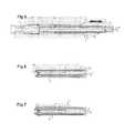
- Fig. 5illustrates an additional phase specific to the invention, namely the release of the tampon with respect to sleeve 12: the tubular casing 2 is slid and the sleeve 12 along the pusher 3 by a movement backwards however that buffer 6 is held well in place by push-button 3. Note that this is longer than in a conventional applicator. All [pusher 3 + envelope 2 and sleeve 12] can be removed no problem after total release of the buffer 6.
- the sleeve 12is shown in Figs. 1 to 4 under the shaped like a hose open at both ends. His proximal end being secured to the envelope 2, it it goes without saying that we can also provide a sleeve initially "closed” at its distal end, either by a cap showing lines of weakness, either by pleating maintained by one or more welding points easily tearable to allow the passage of the tampon 6.
- the material used to manufacture the sleeve 12can be extremely thin, on the order of that used for condoms.
- the sleevemust have a good flexibility and slip easily, which results in a maximum softness on the vaginal wall but it is not necessary that it also has qualities exceptional mechanical properties. Indeed, it is enough that his diameter is slightly greater than that of buffer 6 for allow effortless and smooth sliding.
- pusher 3 of the present applicator 1is longer than the pusher of a normal applicator. It must indeed have a length greater than the sum of the envelope lengths tubular 2 and the sleeve 12 deployed and allow the clearance described in Fig. 5.
- the elongation compared to a plastic applicator classicis only 5.5 cm, and a few mm per compared to a glossy cardboard applicator.
- the length of the withdrawal cord 19 of buffer 6is obviously adapted to this peculiarity.
- FIG. 6shows a applicator provided with a telescopic pusher 3. Stops 18 or a quarter turn lock allows lock the two elements 20, 21 of the pusher 3 to time of arming the applicator 1.
- Fig. 6another possibility of fixing the sleeve 12, which is here glued inside the walls of envelope 2.
- Fig. 7shows another possible embodiment advantage of this applicator 1: the sleeve 12 is here glued or welded to the entire envelope 2, which allows the use for the envelope 2 of a material having a lesser degree of finish while further strengthening the comfort at the introduction.
- the possible presence of a lubricantis in this case limited to the folded part of the sleeve 12.
- applicator 1has been described in the context particular of the establishment of a hygienic tampon, it it goes without saying that its principle also applies to the introduction and placement of other objects or medical devices such as probes, catheters, micro cameras, certain types of drugs, etc., and in general any type of elements that may prove to be aggressive for the wall of an organ.
Landscapes
- Health & Medical Sciences (AREA)
- Epidemiology (AREA)
- Engineering & Computer Science (AREA)
- Biomedical Technology (AREA)
- Heart & Thoracic Surgery (AREA)
- Vascular Medicine (AREA)
- Life Sciences & Earth Sciences (AREA)
- Animal Behavior & Ethology (AREA)
- General Health & Medical Sciences (AREA)
- Public Health (AREA)
- Veterinary Medicine (AREA)
- Absorbent Articles And Supports Therefor (AREA)
Abstract
Description
Translated fromFrenchL'invention concerne un applicateur pourl'introduction d'un objet solide dans un orifice naturel ducorps humain.The invention relates to an applicator forthe introduction of a solid object into a natural orifice of thehuman body.
L'invention concerne plus particulièrement les tamponshygiéniques. Son principe s'applique également àl'introduction et la mise en place d'autres objets ouappareillages du domaine médical tels que sondes,cathéters, micro caméras, etc.The invention relates more particularly to tamponshygienic. Its principle also applies tothe introduction and placement of other objects ormedical devices such as probes,catheters, micro cameras, etc.
Un des inconvénients majeurs des tampons hygiéniquesest l'inconfort que suscite leur mise en place.One of the major drawbacks of tamponsis the discomfort that arises from their placement.
Quoique la mise au point d'un applicateur formé d'untube et d'un poussoir (connu dans EP 0 551 758) aitconstitué une avancée dans le domaine, il n'en reste pasmoins beaucoup à faire pour rendre cette opération rapideet indolore.Although the development of an applicator formed of atube and a pusher (known in EP 0 551 758)a breakthrough in the field, there are none leftless to do to make this quickand painless.
Un des problèmes réside dans le frottement de l'objettel qu'un tampon après qu'il soit sorti de l'applicateur,surtout durant les menstruations, les muqueuses étant à cemoment fort sensibles. De nombreux fabricants ont tenté dedévelopper des solutions impliquant l'intégration deproduits lubrifiants tels que des gels, soit directementdans les tampons (DE 3739163, GB 2 056 083), soit dans descavités ou des capsules incorporées dans les applicateurs(US 3,139,886; US 4,421,504).One of the problems lies in the friction of the objectsuch as a tampon after it comes out of the applicator,especially during menstruation, the mucous membranes being at thisvery sensitive moment. Many manufacturers have attempted todevelop solutions involving the integration oflubricants such as gels, either directlyin the buffers (DE 3739163,
Un des inconvénients des lubrifiants est qu'ilspeuvent limiter les capacités d'absorption des tampons. Parailleurs, ces lubrifiants donnant, au toucher, uneimpression graisseuse doivent être libérés in situ, fautede quoi l'applicateur est peu agréable à manipuler.One of the disadvantages of lubricants is that theymay limit the absorption capacity of the tampon. Throughelsewhere, these lubricants giving, to the touch, agreasy print must be released in situ, faultwhat the applicator is not very pleasant to handle.
Une autre approche consiste à arrondir autant quepossible la tête de l'applicateur. Dans ce but, certains applicateurs présentent une extrémité distale en formed'ogive, formée de découpes en pétale qui s'ouvrent versl'extérieur au passage du tampon (voir EP 0 551 758). Unproblème connu est que ces pétales peuvent pincer la chairlors du retrait de l'applicateur.Another approach is to round as much aspossible the applicator head. To this end, someapplicators have a distal shaped endwarhead, formed of petal cutouts that open towardsthe outside when the tampon passes (see EP 0 551 758). Aknown problem is that these petals can pinch the fleshwhen removing the applicator.
On a donc cherché à développer un applicateur facile àinsérer et qui diminue le frottement de l'objet tel qu'untampon contre les parois de l'orifice.We therefore sought to develop an easy-to-use applicatorinsert and which decreases the friction of the object such as apad against the walls of the orifice.
L'objet de l'invention est un applicateur pourl'insertion d'un objet dans un orifice naturel du corpshumain comprenant le dit objet inséré dans une enveloppetubulaire et un poussoir destiné à faire sortir le ditobjet de l'enveloppe tubulaire . Cet applicateur comprendun manchon souple fixé concentriquement à l'enveloppe,entre l'extrémité distale de cette enveloppe et l'objet. Lemanchon souple se déploie autour de l'objet lorsque celui-cisort de l'enveloppe sous l'effet du poussoir. Lepoussoir présente une longueur suffisante pour maintenirl'objet en place lorsqu'on dégage l'objet du manchon enfaisant coulisser l'enveloppe et le manchon dans le senscontraire à celui de l'insertion.The object of the invention is an applicator forinserting an object into a natural opening in the bodyhuman including the said object inserted in an envelopetubular and a pusher intended to bring out the saidobject of the tubular casing. This applicator includesa flexible sleeve fixed concentrically to the envelope,between the distal end of this envelope and the object. Theflexible sleeve deploys around the object when itcomes out of the envelope under the effect of the pusher. Thepusher has sufficient length to maintainthe object in place when the object is released from the sleevesliding the envelope and the sleeve in the directioncontrary to that of insertion.
Suivant un mode de réalisation avantageuxl'applicateur est conformé à l'anatomie féminine, l'objet àinsérer étant un tampon hygiénique.According to an advantageous embodimentthe applicator conforms to the female anatomy, the object toinsert being a hygienic tampon.
Le manchon souple peut être fixé avantageusement à lapartie distale de l'enveloppe, à l'extérieur de la partiedistale de l'enveloppe ou l'intérieur de l'enveloppe.The flexible sleeve can be advantageously attached to thedistal part of the envelope, outside the partdistal of the envelope or the interior of the envelope.
Suivant un mode de réalisation avantageux, le manchonsouple comprend une partie disposée le long de la paroiextérieure de l'enveloppe.According to an advantageous embodiment, the sleeveflexible includes a part arranged along the walloutside of the envelope.
Le manchon souple est, suivant un mode de réalisationavantageux, initialement ouvert à son extrémité distale. Suivant un autre mode de réalisation avantageux le manchonsouple est initialement fermé à son extrémité distale etcomprend à cette extrémité une partie destinée à se romprefacilement.The flexible sleeve is, according to one embodimentadvantageous, initially open at its distal end.According to another advantageous embodiment, the sleeveflexible is initially closed at its distal end andincludes at this end a part intended to breakeasily.
Le matériau du manchon souple présente de préférenceun faible coefficient de frottement. Sa face extérieurepeut aussi être enduite au moins sur une partie de salongueur d'une substance lubrifiante. Dans ce cas, suivantun mode de réalisation avantageux, la partie distale dutampon est enduite d'une substance anti-absorbante.The material of the flexible sleeve preferably hasa low coefficient of friction. Its outer facecan also be coated on at least part of itslength of a lubricating substance. In this case, followingan advantageous embodiment, the distal part of thepad is coated with an anti-absorbent substance.
Suivant un mode de réalisation préféré le poussoircomprend deux parties télescopiques et un dispositif deverrouillage de ces deux parties entre elles.According to a preferred embodiment the pusherincludes two telescopic parts and a device forlocking these two parts together.
Suivant un mode de réalisation avantageux le poussoircomprend des repères tactiles, ce qui permet une évaluationplus précise de sa position avant le retrait.According to an advantageous embodiment, the pusherincludes tactile cues, allowing assessmentmore precise from its position before removal.
Un avantage de l'invention est de permettred'introduire dans le corps des objets aux formes ou auxcontours relativement agressifs avec un minimum d'inconfort.Cet avantage est particulièrement marqué dans le cas del'introduction de tampons hygiéniques durant les périodes demenstruation, qui se fait sans douleur.An advantage of the invention is to allowintroduce objects into the body with shapes orrelatively aggressive contours with minimal discomfort.This advantage is particularly marked in the case ofthe introduction of hygienic tampons during periods ofmenstruation, which is painless.
Un autre avantage de l'invention réside dans lapossibilité de rectifier la position de l'objet avant lelargage.Another advantage of the invention lies in thepossibility of correcting the position of the object beforerelease.
D'autres particularités et avantages de l'inventionressortiront de la description ci-après de modes deréalisation particuliers de l'invention, référence étantfaite aux dessins annexés dans lesquels :
L'applicateur 1 de la Fig. 1, qui est illustré icidans son rôle d'applicateur 1 de tampon hygiénique, possèdeen commun avec un applicateur classique une enveloppetubulaire 2 et un poussoir 3, représenté ici en position derepos, entourant l'objet à insérer, soit un tampon 6.L'enveloppe affecte à sa partie distale 8 une forme enogive obtenue par une découpe en pétales 10.The applicator 1 of FIG. 1, which is illustrated herein its role of applicator 1 of hygienic tampon, hastogether with a conventional applicator an envelopetubular 2 and a pusher 3, shown here in positionrest, surrounding the object to be inserted, i.e. a buffer 6.The envelope assigns to its distal part 8 a shape inwarhead obtained by cutting
À la différence d'un applicateur classique, le présentapplicateur comprend un manchon 12 formé d'une membranesouple à faible coefficient de frottement fixéconcentriquement à l'enveloppe 2. Ce manchon 12 est fixéici à l'extérieur de l'enveloppe tubulaire 2, recouvrantson extrémité distale 8, puis est replié à l'intérieur del'enveloppe 2, entre l'extrémité distale 8 et le tampon 6.Le rôle du manchon 12 sera décrit en se référant auxFigures 2 à 4.Unlike a conventional applicator, the presentapplicator comprises a
La Fig. 2 représente l'applicateur 1 après que lepoussoir 3 ait été armé (c'est-à-dire tiré vers l'arrièreet dégagé du tampon 6) et que l'applicateur 1 ait été misen place dans l'orifice ad hoc 13, en l'occurrence le vagin13.Fig. 2 represents the applicator 1 after thepusher 3 has been armed (i.e. pulled backand released from the buffer 6) and that the applicator 1 has been putin place in the
Des repères tactiles 14 permettent, en conjonctionavec une garde 15, de positionner l'enveloppe tubulaire 2 àla profondeur appropriée. Il est en effet impératif que letampon 6 ne pénètre pas trop loin et par exemple reste endeçà de la matrice 16.
La Fig. 3 montre le poussoir 3 en phase d'enfoncement: le tampon 6, pressé contre la partie distale 8 del'enveloppe tubulaire 2, écarte les découpes en pétales 10et force le manchon 12 à se déployer vers l'extérieur. Lamembrane du manchon 12 présentant un faible coefficient defrottement se déploie dans le vagin 13, entourant le tampon6 au fur et à mesure de sa progression, qui se fait avectrès peu d'effort.Fig. 3 shows pusher 3 in the depressing phase: the tampon 6, pressed against the distal part 8 ofthe
A la Fig. 4, le tampon 6 est sorti de l'enveloppe 2 etoccupe sa position terminale. On constate que la longueurdu manchon 12 correspond à celle du tampon 6. Ce dernierétant toujours entouré par le manchon 12, est toujourssolidaire de l'applicateur 1, du fait de la faibleadhérence du manchon 12 sur la paroi du vagin 14. Il estdonc possible, à ce stade, de rectifier légèrement laposition du tampon 6(ce qui n'est pas le cas avec unapplicateur classique). La présence de seconds repèrestactiles 17, ménagés sur le poussoir, permet de vérifierque la manoeuvre a été effectuée de façon correcte.In Fig. 4, the buffer 6 has come out of the
La Fig. 5 illustre une phase supplémentaire propre àl'invention, à savoir le dégagement du tampon par rapportau manchon 12 : on fait coulisser l'enveloppe tubulaire 2et le manchon 12 le long du poussoir 3 par un mouvement vers l'arrière cependant que le tampon 6 est maintenu bienen place par le poussoir 3. On notera que ce dernier estplus long que dans un applicateur classique. L'ensemble[poussoir 3 + enveloppe 2 et manchon 12] peut être retirésans problème après dégagement total du tampon 6.Fig. 5 illustrates an additional phase specific tothe invention, namely the release of the tampon with respect tosleeve 12: the
Le manchon 12 est représenté aux Fig. 1 à 4 sous laforme d'un boyau ouvert à ses deux extrémités. Sonextrémité proximale étant solidarisée à l'enveloppe 2, ilva de soi que l'on peut également prévoir un manchoninitialement "fermé" à son extrémité distale, soit par unecalotte présentant des lignes d'affaiblissement, soit parun plissage maintenu par un ou plusieurs points de souduresfacilement déchirables pour permettre le passage du tampon6.The
Le matériau utilisé pour la fabrication du manchon 12peut être extrêmement mince, de l'ordre de celui utilisépour des préservatifs. Le manchon doit présenter une bonnesouplesse et glisser facilement, ce qui se traduit par unmaximum de douceur sur la paroi vaginale, mais il n'est pasnécessaire qu'il présente par ailleurs des qualitésmécaniques exceptionnelles. En effet, il suffit que sondiamètre soit légèrement supérieur à celui du tampon 6 pourpermettre un glissement sans efforts et sans à-coups. Onpeut choisir un matériau présentant intrinsèquement unfaible coefficient de frottement sur la paroi du vagin 14ou opter pour un matériau enduit sur tout ou partie de sasurface externe d'un lubrifiant connu par ailleurs. Il aété vérifié expérimentalement que le contact du tampon 6avec la surface d'un manchon 12 enduite de lubrifiantn'altère virtuellement pas les qualités d'absorption dutampon 6. Le contact ne se fait de toute façon que sur lapartie distale du tampon 6. Dans certains cas, on peut toutefois prévoir d'imbiber la pointe du tampon 6 avec unproduit neutralisant tout effet d'interaction.The material used to manufacture the
Il ressort clairement de la Fig. 4 que le poussoir 3du présent applicateur 1 est plus long que le poussoir d'unapplicateur normal. Il doit en effet avoir une longueursupérieure à la somme des longueurs de l'enveloppetubulaire 2 et du manchon 12 déployé et permettre ledégagement décrit à la Fig.5. En jouant sur les longueursrelatives des différents éléments, on constate cependantque l'allongement par rapport à un applicateur plastiqueclassique n'est guère que de 5,5 cm, et de quelques mm parrapport à un applicateur en carton glacé. La longueur ducordon de retrait 19 du tampon 6 est évidemment adaptée àcette particularité.It is clear from FIG. 4 as pusher 3of the present applicator 1 is longer than the pusher of anormal applicator. It must indeed have a lengthgreater than the sum of the envelope lengthstubular 2 and the
Un surcroít d'encombrement pouvant nuire au caractèrediscret de l'applicateur 1 en ce qui concerne son emploipour des tampons hygiéniques 6 on a cherché à réaliser unmodèle particulièrement compact. La Fig. 6 montre unapplicateur muni d'un poussoir 3 télescopique. Des butées18 ou un verrouillage quart de tour permettent deverrouiller les deux éléments 20, 21 du poussoir 3 aumoment de l'armement de l'applicateur 1. On a égalementreprésenté à la Fig. 6 une autre possibilité de fixation dumanchon 12, qui est ici collé à l'intérieur des parois del'enveloppe 2.Additional clutter that can harm characterdiscreet of the applicator 1 with regard to its usefor hygienic tampons 6 we tried to achieve aparticularly compact model. Fig. 6 shows aapplicator provided with a telescopic pusher 3. Stops18 or a quarter turn lock allowslock the two elements 20, 21 of the pusher 3 totime of arming the applicator 1. We also haveshown in Fig. 6 another possibility of fixing the
La Fig. 7 montre une autre possibilité de réalisationintéressante du présent applicateur 1 : le manchon 12 estici collé ou soudé sur l'ensemble de l'enveloppe 2, ce quipermet d'utiliser pour l'enveloppe 2 un matériau présentantun moindre degré de finition tout en renforçant encore leconfort à l'introduction. La présence éventuelle d'unlubrifiant est dans ce cas limitée à la partie repliée dumanchon 12.Fig. 7 shows another possible embodimentadvantage of this applicator 1: the
On remarquera que la présence du manchon 12, qu'ilsoit fixé à l'intérieur ou à l'extérieur de l'enveloppe 2,permet d'éviter tout pincement de la chair par leséventuelles découpes en pétales 10.It will be noted that the presence of the
Bien que l'applicateur 1 ait été décrit dans le cadreparticulier de la mise en place d'un tampon hygiénique, ilva de soi que son principe s'applique également àl'introduction et la mise en place d'autres objets ouappareillages du domaine médical tels que sondes,cathéters, micro caméras, certains types de médicaments,etc., et en général tout type d'éléments pouvant s'avéreragressifs pour la paroi d'un organe.Although applicator 1 has been described in the contextparticular of the establishment of a hygienic tampon, itit goes without saying that its principle also applies tothe introduction and placement of other objects ormedical devices such as probes,catheters, micro cameras, certain types of drugs,etc., and in general any type of elements that may prove to beaggressive for the wall of an organ.
Claims (13)
Translated fromFrenchPriority Applications (4)
| Application Number | Priority Date | Filing Date | Title |
|---|---|---|---|
| DE60213757TDE60213757T2 (en) | 2002-02-05 | 2002-02-05 | tampon |
| EP02100107AEP1336398B1 (en) | 2002-02-05 | 2002-02-05 | Applicator for tampons |
| AT02100107TATE335455T1 (en) | 2002-02-05 | 2002-02-05 | TAMPON APPLICATOR |
| US10/315,691US7331937B2 (en) | 2002-02-05 | 2002-12-10 | Applicator for objects such as tampons |
Applications Claiming Priority (1)
| Application Number | Priority Date | Filing Date | Title |
|---|---|---|---|
| EP02100107AEP1336398B1 (en) | 2002-02-05 | 2002-02-05 | Applicator for tampons |
Publications (2)
| Publication Number | Publication Date |
|---|---|
| EP1336398A1true EP1336398A1 (en) | 2003-08-20 |
| EP1336398B1 EP1336398B1 (en) | 2006-08-09 |
Family
ID=27619176
Family Applications (1)
| Application Number | Title | Priority Date | Filing Date |
|---|---|---|---|
| EP02100107AExpired - LifetimeEP1336398B1 (en) | 2002-02-05 | 2002-02-05 | Applicator for tampons |
Country Status (4)
| Country | Link |
|---|---|
| US (1) | US7331937B2 (en) |
| EP (1) | EP1336398B1 (en) |
| AT (1) | ATE335455T1 (en) |
| DE (1) | DE60213757T2 (en) |
Cited By (1)
| Publication number | Priority date | Publication date | Assignee | Title |
|---|---|---|---|---|
| WO2005004775A1 (en)* | 2003-07-02 | 2005-01-20 | Birchbob International Sa | Applicator for objects such as tampons |
Families Citing this family (35)
| Publication number | Priority date | Publication date | Assignee | Title |
|---|---|---|---|---|
| WO2004103213A1 (en)* | 2003-05-22 | 2004-12-02 | Contipi Ltd. | Device for the prevention of urinary incontinence in females |
| WO2005087153A2 (en) | 2004-03-18 | 2005-09-22 | Contipi Ltd. | Apparatus for the treatment of feminine pelvic organ prolapse |
| MXPA06010653A (en) | 2004-03-18 | 2007-03-26 | Contipi Ltd | Apparatus for the prevention of urinary incontinence in females. |
| US7845380B2 (en)* | 2004-05-14 | 2010-12-07 | Mcneil-Ppc, Inc. | Intravaginal device with fluid transport plates |
| US8653322B2 (en)* | 2004-05-14 | 2014-02-18 | Mcneil-Ppc, Inc. | Intravaginal device with fluid transport plates |
| US20050256484A1 (en) | 2004-05-14 | 2005-11-17 | Chase David J | Method of using an intravaginal device with fluid transport plates |
| US20050277904A1 (en)* | 2004-05-14 | 2005-12-15 | Chase David J | Tampon with flexible panels |
| US7618403B2 (en) | 2004-05-14 | 2009-11-17 | Mcneil-Ppc, Inc. | Fluid management device with fluid transport element for use within a body |
| US8480833B2 (en)* | 2004-05-14 | 2013-07-09 | Mcneil-Ppc, Inc. | Intravaginal device with fluid transport plates and methods of making |
| US8247642B2 (en)* | 2004-05-14 | 2012-08-21 | Mcneil-Ppc, Inc. | Fluid management device with fluid transport element for use within a body |
| US8864640B2 (en)* | 2004-05-14 | 2014-10-21 | Mcneil-Ppc, Inc. | Methods of packaging intravaginal device |
| US20050256485A1 (en)* | 2004-05-14 | 2005-11-17 | Samuel Carasso | Method of using intravaginal device with fluid transport plates |
| JP4266186B2 (en)* | 2004-05-21 | 2009-05-20 | 西原 梨沙 | Body cavity occlusion device and body treatment device |
| US20060004319A1 (en)* | 2004-06-30 | 2006-01-05 | The Procter & Gamble Company | Applicator with low placement indicia on the insertion member |
| JP2008537497A (en)* | 2005-03-17 | 2008-09-18 | コンティピ リミテッド | Urinary incontinence improvement device for women |
| EP1863399B1 (en)* | 2005-03-17 | 2022-08-17 | Kimberly-Clark Worldwide, Inc. | Apparatuses for the amelioration of urinary incontinence in females |
| RU2396924C2 (en)* | 2005-03-17 | 2010-08-20 | Контипи Лтд. | Devices for reduction of urinary incontinence in women |
| US7993667B2 (en)* | 2005-03-25 | 2011-08-09 | Kimberly-Clark Worldwide, Inc. | Methods of manufacturing a medicated tampon assembly |
| US7744556B2 (en)* | 2005-03-25 | 2010-06-29 | Kimberly-Clark Worldwide, Inc. | Delivery tube assembly for an applicator |
| US20070032758A1 (en)* | 2005-03-31 | 2007-02-08 | Chase David J | Lubricated tampon applicator |
| IL176883A (en) | 2005-09-22 | 2013-09-30 | Eliahu Eliachar | Apparatus for the amelioration of urinary incontinence in females |
| US20070128254A1 (en)* | 2005-12-07 | 2007-06-07 | Heuer Daniel J | Methods of attaching a dosage form to a medicated tampon assembly |
| US20070141118A1 (en)* | 2005-12-15 | 2007-06-21 | Damico Joyce A | Layered dosage form for a medicated tampon assembly |
| RU2479284C2 (en)* | 2007-06-11 | 2013-04-20 | Контипи Лтд. | Tension-adjusted ring for female urinary incontinence relief |
| US9339363B2 (en) | 2007-10-01 | 2016-05-17 | Kimberly Clark Worldwide, Inc. | Management of urinary incontinence in females |
| US8651109B2 (en)* | 2008-04-23 | 2014-02-18 | Contipi Ltd. | Pessaries for prolapse alleviation |
| CA2724504A1 (en)* | 2008-05-16 | 2009-11-19 | Rwip, Llc | Delivery device with invertible diaphragm |
| US20110190686A1 (en)* | 2010-01-29 | 2011-08-04 | Margaret Henderson Hasse | Applicator for feminine hygiene devices |
| IT1399254B1 (en)* | 2010-04-07 | 2013-04-11 | Battista | DEVICE FOR HEMOSTATIC MEDICATION IN ANO-RECTAL OR VAGINAL CHANNELS. |
| WO2012126000A2 (en)* | 2011-03-17 | 2012-09-20 | Emory University | Delivery devices and methods for delivering therapeutic agents |
| WO2012125999A2 (en)* | 2011-03-17 | 2012-09-20 | Emory University | Delivery devices and methods for delivering therapeutic agents |
| AU2011380295A1 (en)* | 2011-11-02 | 2014-05-15 | Caroline ABDON | Tampon-applicator assembly |
| JP5715993B2 (en) | 2012-09-12 | 2015-05-13 | ユニ・チャーム株式会社 | Tampon applicator |
| RO129921A2 (en)* | 2013-06-17 | 2014-12-30 | V-Veil-Shop Ltd. | Assembly for vaginal insertion |
| CN105395307B (en)* | 2015-12-08 | 2018-02-16 | 张波 | A kind of female condom device for posting and its application method |
Citations (9)
| Publication number | Priority date | Publication date | Assignee | Title |
|---|---|---|---|---|
| FR2002723A1 (en)* | 1968-02-27 | 1969-10-31 | Kimberly Clark Co | |
| WO1983001741A1 (en)* | 1981-11-17 | 1983-05-26 | Bunce, Philip | Catheter-type sampling device |
| EP0104039A1 (en)* | 1982-09-17 | 1984-03-28 | Smith and Nephew Associated Companies p.l.c. | Tampons and applicators |
| FR2546399A1 (en)* | 1983-05-24 | 1984-11-30 | Serimed Ste Civile | APPLICATOR FOR THE PLACEMENT OF AN OBJECT IN THE VAGINA OF A FEMALE ANIMAL |
| GB2153684A (en)* | 1984-02-01 | 1985-08-29 | Smith & Nephew Ass | Tampon insertion device |
| EP0349222A2 (en)* | 1988-06-30 | 1990-01-03 | Tambrands Limited | Improvement in 2-piece tampon applicators |
| US4921474A (en)* | 1985-10-18 | 1990-05-01 | Uni-Charm Corporation | Sanitary tampon applicator |
| US5676647A (en)* | 1995-06-22 | 1997-10-14 | Cimber; Hugo | Tampon applicator |
| US5928183A (en)* | 1994-08-22 | 1999-07-27 | Kimberly-Clark Worldwide, Inc. | Tampon applicator with multi-layered tips |
Family Cites Families (11)
| Publication number | Priority date | Publication date | Assignee | Title |
|---|---|---|---|---|
| US3139886A (en)* | 1962-09-12 | 1964-07-07 | Richard B Tallman | Tampon applicator with lubricating feature |
| US3335726A (en)* | 1965-03-08 | 1967-08-15 | Maranto Loretta Margaret | Lubricating tampon |
| US4211225A (en)* | 1978-07-19 | 1980-07-08 | Dan Sibalis | Tampon with a collapsible and invertible shroud |
| US4286594A (en)* | 1979-05-29 | 1981-09-01 | Cunningham Thomas W | Applicator and tampon |
| US4318404A (en)* | 1979-05-29 | 1982-03-09 | Cunningham Thomas W | Applicator and tampon |
| GB2056283A (en) | 1979-07-23 | 1981-03-18 | Kimberly Clark Co | Tampon |
| US4413986A (en)* | 1980-11-10 | 1983-11-08 | Jacobs Henry R | Tampon assembly with means for sterile insertion |
| US4421504A (en)* | 1981-09-08 | 1983-12-20 | Kline Larry H | Lubricating object injector utilizing a single plunger |
| DE3739163A1 (en) | 1987-11-19 | 1989-06-01 | Ver Papierwerke Ag | Tampon for female hygiene and manufacturing method |
| US4955906A (en)* | 1989-01-12 | 1990-09-11 | Coggins Peter R | Mammary prosthesis injector |
| US6762897B1 (en) | 1997-09-08 | 2004-07-13 | Kabushiki Kaisha Yaskawa Denki | Magnetic encoder apparatus |
- 2002
- 2002-02-05DEDE60213757Tpatent/DE60213757T2/ennot_activeExpired - Fee Related
- 2002-02-05ATAT02100107Tpatent/ATE335455T1/ennot_activeIP Right Cessation
- 2002-02-05EPEP02100107Apatent/EP1336398B1/ennot_activeExpired - Lifetime
- 2002-12-10USUS10/315,691patent/US7331937B2/ennot_activeExpired - Fee Related
Patent Citations (9)
| Publication number | Priority date | Publication date | Assignee | Title |
|---|---|---|---|---|
| FR2002723A1 (en)* | 1968-02-27 | 1969-10-31 | Kimberly Clark Co | |
| WO1983001741A1 (en)* | 1981-11-17 | 1983-05-26 | Bunce, Philip | Catheter-type sampling device |
| EP0104039A1 (en)* | 1982-09-17 | 1984-03-28 | Smith and Nephew Associated Companies p.l.c. | Tampons and applicators |
| FR2546399A1 (en)* | 1983-05-24 | 1984-11-30 | Serimed Ste Civile | APPLICATOR FOR THE PLACEMENT OF AN OBJECT IN THE VAGINA OF A FEMALE ANIMAL |
| GB2153684A (en)* | 1984-02-01 | 1985-08-29 | Smith & Nephew Ass | Tampon insertion device |
| US4921474A (en)* | 1985-10-18 | 1990-05-01 | Uni-Charm Corporation | Sanitary tampon applicator |
| EP0349222A2 (en)* | 1988-06-30 | 1990-01-03 | Tambrands Limited | Improvement in 2-piece tampon applicators |
| US5928183A (en)* | 1994-08-22 | 1999-07-27 | Kimberly-Clark Worldwide, Inc. | Tampon applicator with multi-layered tips |
| US5676647A (en)* | 1995-06-22 | 1997-10-14 | Cimber; Hugo | Tampon applicator |
Cited By (1)
| Publication number | Priority date | Publication date | Assignee | Title |
|---|---|---|---|---|
| WO2005004775A1 (en)* | 2003-07-02 | 2005-01-20 | Birchbob International Sa | Applicator for objects such as tampons |
Also Published As
| Publication number | Publication date |
|---|---|
| EP1336398B1 (en) | 2006-08-09 |
| DE60213757D1 (en) | 2006-09-21 |
| US7331937B2 (en) | 2008-02-19 |
| DE60213757T2 (en) | 2007-08-16 |
| ATE335455T1 (en) | 2006-09-15 |
| US20030149392A1 (en) | 2003-08-07 |
Similar Documents
| Publication | Publication Date | Title |
|---|---|---|
| EP1336398B1 (en) | Applicator for tampons | |
| EP1156761B1 (en) | Device for injecting an intraocular lens made of flexible material | |
| FR2499404A1 (en) | INSTRUMENT FACILITATING THE HOUSING OF AN INTRAUTERIN DEVICE IN A PLACEMENT TUBE | |
| FR2482450A1 (en) | MEANS OF EXTERNAL URINARY EVACUATION | |
| FR2712485A1 (en) | Device for subcutaneous identification of a medical prosthesis and corresponding prosthesis. | |
| EP0091895A1 (en) | Device for the suprapubic drainage of the bladder introduced through the urethra | |
| EP3352684B1 (en) | System for treating an epistaxis | |
| FR2484843A1 (en) | MEDICAL DILATOR | |
| US10779996B2 (en) | Vaginal insertion assembly | |
| WO2003055419A1 (en) | Medical device for explantation | |
| EP3448226A1 (en) | Endoscopic cap with reinforced wall | |
| FR2467593A1 (en) | TAMPON | |
| EP1263361B1 (en) | Device for inserting a t-shaped intra-uterine device | |
| WO1991008011A1 (en) | Injection material (syringe and needle) unusable after a single use | |
| EP0266469A1 (en) | Oesophagus catheter | |
| WO2005004775A1 (en) | Applicator for objects such as tampons | |
| JP4212464B2 (en) | Sanitary tampons | |
| FR2533128A1 (en) | DEVICE AND METHOD FOR AIDING THE RELEASE OF GASES FROM THE DIGESTIVE APPARATUS OF A HUMAN BEING AND FOR SUPPLYING SOUNDS | |
| EP2720650B1 (en) | Device for delivering a stent in a blood vessel or similar. | |
| FR2524309A1 (en) | Instrument for administering suppository by insertion in body orifice - uses syringe piston to eject suppository from coaxially fitted extension sleeve | |
| BE1007545A3 (en) | Vein stripping system | |
| FR2684004A1 (en) | Medical syringe fitted with an articulated and lockable needle protection | |
| EP0158619A2 (en) | Surgical instrument | |
| WO1998005266A1 (en) | Device for preventing male urinary incontinence | |
| BE437937A (en) |
Legal Events
| Date | Code | Title | Description |
|---|---|---|---|
| PUAI | Public reference made under article 153(3) epc to a published international application that has entered the european phase | Free format text:ORIGINAL CODE: 0009012 | |
| AK | Designated contracting states | Designated state(s):AT BE CH CY DE DK ES FI FR GB GR IE IT LI LU MC NL PT SE TR | |
| AX | Request for extension of the european patent | Extension state:AL LT LV MK RO SI | |
| 17P | Request for examination filed | Effective date:20040107 | |
| AKX | Designation fees paid | Designated state(s):AT BE CH CY DE DK ES FI FR GB GR IE IT LI LU MC NL PT SE TR | |
| 17Q | First examination report despatched | Effective date:20050427 | |
| RAP1 | Party data changed (applicant data changed or rights of an application transferred) | Owner name:BIRCHBOB INTERNATIONAL SA | |
| RIN1 | Information on inventor provided before grant (corrected) | Inventor name:ARNOULD, MARC | |
| GRAP | Despatch of communication of intention to grant a patent | Free format text:ORIGINAL CODE: EPIDOSNIGR1 | |
| GRAS | Grant fee paid | Free format text:ORIGINAL CODE: EPIDOSNIGR3 | |
| GRAA | (expected) grant | Free format text:ORIGINAL CODE: 0009210 | |
| AK | Designated contracting states | Kind code of ref document:B1 Designated state(s):AT BE CH CY DE DK ES FI FR GB GR IE IT LI LU MC NL PT SE TR | |
| PG25 | Lapsed in a contracting state [announced via postgrant information from national office to epo] | Ref country code:IT Free format text:LAPSE BECAUSE OF FAILURE TO SUBMIT A TRANSLATION OF THE DESCRIPTION OR TO PAY THE FEE WITHIN THE PRESCRIBED TIME-LIMIT;WARNING: LAPSES OF ITALIAN PATENTS WITH EFFECTIVE DATE BEFORE 2007 MAY HAVE OCCURRED AT ANY TIME BEFORE 2007. THE CORRECT EFFECTIVE DATE MAY BE DIFFERENT FROM THE ONE RECORDED. Effective date:20060809 Ref country code:AT Free format text:LAPSE BECAUSE OF FAILURE TO SUBMIT A TRANSLATION OF THE DESCRIPTION OR TO PAY THE FEE WITHIN THE PRESCRIBED TIME-LIMIT Effective date:20060809 Ref country code:NL Free format text:LAPSE BECAUSE OF FAILURE TO SUBMIT A TRANSLATION OF THE DESCRIPTION OR TO PAY THE FEE WITHIN THE PRESCRIBED TIME-LIMIT Effective date:20060809 Ref country code:IE Free format text:LAPSE BECAUSE OF FAILURE TO SUBMIT A TRANSLATION OF THE DESCRIPTION OR TO PAY THE FEE WITHIN THE PRESCRIBED TIME-LIMIT Effective date:20060809 Ref country code:FI Free format text:LAPSE BECAUSE OF FAILURE TO SUBMIT A TRANSLATION OF THE DESCRIPTION OR TO PAY THE FEE WITHIN THE PRESCRIBED TIME-LIMIT Effective date:20060809 | |
| REG | Reference to a national code | Ref country code:GB Ref legal event code:FG4D Free format text:NOT ENGLISH | |
| REG | Reference to a national code | Ref country code:CH Ref legal event code:EP | |
| REG | Reference to a national code | Ref country code:IE Ref legal event code:FG4D Free format text:LANGUAGE OF EP DOCUMENT: FRENCH | |
| REF | Corresponds to: | Ref document number:60213757 Country of ref document:DE Date of ref document:20060921 Kind code of ref document:P | |
| GBT | Gb: translation of ep patent filed (gb section 77(6)(a)/1977) | Effective date:20061016 | |
| PG25 | Lapsed in a contracting state [announced via postgrant information from national office to epo] | Ref country code:SE Free format text:LAPSE BECAUSE OF FAILURE TO SUBMIT A TRANSLATION OF THE DESCRIPTION OR TO PAY THE FEE WITHIN THE PRESCRIBED TIME-LIMIT Effective date:20061109 Ref country code:DK Free format text:LAPSE BECAUSE OF FAILURE TO SUBMIT A TRANSLATION OF THE DESCRIPTION OR TO PAY THE FEE WITHIN THE PRESCRIBED TIME-LIMIT Effective date:20061109 | |
| PG25 | Lapsed in a contracting state [announced via postgrant information from national office to epo] | Ref country code:ES Free format text:LAPSE BECAUSE OF FAILURE TO SUBMIT A TRANSLATION OF THE DESCRIPTION OR TO PAY THE FEE WITHIN THE PRESCRIBED TIME-LIMIT Effective date:20061120 | |
| PG25 | Lapsed in a contracting state [announced via postgrant information from national office to epo] | Ref country code:PT Free format text:LAPSE BECAUSE OF FAILURE TO SUBMIT A TRANSLATION OF THE DESCRIPTION OR TO PAY THE FEE WITHIN THE PRESCRIBED TIME-LIMIT Effective date:20070109 | |
| NLV1 | Nl: lapsed or annulled due to failure to fulfill the requirements of art. 29p and 29m of the patents act | ||
| PG25 | Lapsed in a contracting state [announced via postgrant information from national office to epo] | Ref country code:CH Free format text:LAPSE BECAUSE OF NON-PAYMENT OF DUE FEES Effective date:20070228 Ref country code:LI Free format text:LAPSE BECAUSE OF NON-PAYMENT OF DUE FEES Effective date:20070228 Ref country code:MC Free format text:LAPSE BECAUSE OF NON-PAYMENT OF DUE FEES Effective date:20070228 | |
| REG | Reference to a national code | Ref country code:IE Ref legal event code:FD4D | |
| PLBE | No opposition filed within time limit | Free format text:ORIGINAL CODE: 0009261 | |
| STAA | Information on the status of an ep patent application or granted ep patent | Free format text:STATUS: NO OPPOSITION FILED WITHIN TIME LIMIT | |
| 26N | No opposition filed | Effective date:20070510 | |
| REG | Reference to a national code | Ref country code:CH Ref legal event code:PL | |
| PG25 | Lapsed in a contracting state [announced via postgrant information from national office to epo] | Ref country code:GR Free format text:LAPSE BECAUSE OF FAILURE TO SUBMIT A TRANSLATION OF THE DESCRIPTION OR TO PAY THE FEE WITHIN THE PRESCRIBED TIME-LIMIT Effective date:20061110 | |
| PGFP | Annual fee paid to national office [announced via postgrant information from national office to epo] | Ref country code:GB Payment date:20080318 Year of fee payment:7 | |
| PGFP | Annual fee paid to national office [announced via postgrant information from national office to epo] | Ref country code:DE Payment date:20080311 Year of fee payment:7 Ref country code:FR Payment date:20080229 Year of fee payment:7 | |
| PGFP | Annual fee paid to national office [announced via postgrant information from national office to epo] | Ref country code:BE Payment date:20080312 Year of fee payment:7 | |
| BERE | Be: lapsed | Owner name:S.A. *BIRCHBOB INTERNATIONAL Effective date:20090228 | |
| PG25 | Lapsed in a contracting state [announced via postgrant information from national office to epo] | Ref country code:LU Free format text:LAPSE BECAUSE OF NON-PAYMENT OF DUE FEES Effective date:20070205 Ref country code:CY Free format text:LAPSE BECAUSE OF FAILURE TO SUBMIT A TRANSLATION OF THE DESCRIPTION OR TO PAY THE FEE WITHIN THE PRESCRIBED TIME-LIMIT Effective date:20060809 | |
| PG25 | Lapsed in a contracting state [announced via postgrant information from national office to epo] | Ref country code:TR Free format text:LAPSE BECAUSE OF FAILURE TO SUBMIT A TRANSLATION OF THE DESCRIPTION OR TO PAY THE FEE WITHIN THE PRESCRIBED TIME-LIMIT Effective date:20060809 | |
| GBPC | Gb: european patent ceased through non-payment of renewal fee | Effective date:20090205 | |
| REG | Reference to a national code | Ref country code:FR Ref legal event code:ST Effective date:20091030 | |
| PG25 | Lapsed in a contracting state [announced via postgrant information from national office to epo] | Ref country code:DE Free format text:LAPSE BECAUSE OF NON-PAYMENT OF DUE FEES Effective date:20090901 | |
| PG25 | Lapsed in a contracting state [announced via postgrant information from national office to epo] | Ref country code:BE Free format text:LAPSE BECAUSE OF NON-PAYMENT OF DUE FEES Effective date:20090228 | |
| PG25 | Lapsed in a contracting state [announced via postgrant information from national office to epo] | Ref country code:GB Free format text:LAPSE BECAUSE OF NON-PAYMENT OF DUE FEES Effective date:20090205 Ref country code:FR Free format text:LAPSE BECAUSE OF NON-PAYMENT OF DUE FEES Effective date:20090302 |