EP1336391A1 - Hernia plate for non permanent deploying - Google Patents
Hernia plate for non permanent deployingDownload PDFInfo
- Publication number
- EP1336391A1 EP1336391A1EP03290346AEP03290346AEP1336391A1EP 1336391 A1EP1336391 A1EP 1336391A1EP 03290346 AEP03290346 AEP 03290346AEP 03290346 AEP03290346 AEP 03290346AEP 1336391 A1EP1336391 A1EP 1336391A1
- Authority
- EP
- European Patent Office
- Prior art keywords
- hernial
- plate according
- balloon
- expansion means
- Prior art date
- Legal status (The legal status is an assumption and is not a legal conclusion. Google has not performed a legal analysis and makes no representation as to the accuracy of the status listed.)
- Granted
Links
- 206010019909HerniaDiseases0.000titledescription2
- 239000004753textileSubstances0.000claimsabstractdescription25
- 230000002441reversible effectEffects0.000claimsabstractdescription4
- 230000037431insertionEffects0.000claimsdescription10
- 238000003780insertionMethods0.000claimsdescription10
- WYTGDNHDOZPMIW-RCBQFDQVSA-NalstonineNatural productsC1=CC2=C3C=CC=CC3=NC2=C2N1C[C@H]1[C@H](C)OC=C(C(=O)OC)[C@H]1C2WYTGDNHDOZPMIW-RCBQFDQVSA-N0.000claimsdescription8
- 239000007788liquidSubstances0.000claimsdescription5
- 239000002184metalSubstances0.000claimsdescription3
- 230000003387muscularEffects0.000claims1
- 210000003815abdominal wallAnatomy0.000description5
- 210000004303peritoneumAnatomy0.000description4
- 238000000605extractionMethods0.000description3
- 239000007943implantSubstances0.000description3
- 230000003187abdominal effectEffects0.000description2
- 210000003205muscleAnatomy0.000description2
- 230000017260vegetative to reproductive phase transition of meristemEffects0.000description2
- 238000004026adhesive bondingMethods0.000description1
- 230000015572biosynthetic processEffects0.000description1
- 239000000835fiberSubstances0.000description1
- 238000009434installationMethods0.000description1
- 239000000463materialSubstances0.000description1
- 230000007170pathologyEffects0.000description1
- 238000009958sewingMethods0.000description1
- 210000001835visceraAnatomy0.000description1
- 238000003466weldingMethods0.000description1
Images


Classifications
- A—HUMAN NECESSITIES
- A61—MEDICAL OR VETERINARY SCIENCE; HYGIENE
- A61F—FILTERS IMPLANTABLE INTO BLOOD VESSELS; PROSTHESES; DEVICES PROVIDING PATENCY TO, OR PREVENTING COLLAPSING OF, TUBULAR STRUCTURES OF THE BODY, e.g. STENTS; ORTHOPAEDIC, NURSING OR CONTRACEPTIVE DEVICES; FOMENTATION; TREATMENT OR PROTECTION OF EYES OR EARS; BANDAGES, DRESSINGS OR ABSORBENT PADS; FIRST-AID KITS
- A61F2/00—Filters implantable into blood vessels; Prostheses, i.e. artificial substitutes or replacements for parts of the body; Appliances for connecting them with the body; Devices providing patency to, or preventing collapsing of, tubular structures of the body, e.g. stents
- A61F2/0063—Implantable repair or support meshes, e.g. hernia meshes
Definitions
- the present inventionrelates, in general, to the field of surgical implants.
- the inventionrelates to a plate hernial of the type that includes a formed pocket first and second textile layers bonded to each other by their respective peripheries, and means of expansion ensuring deployment of the pocket behind the internal face of a muscle wall.
- the implant described in this previous documenttakes the form of a cushion filled with fibers intended to be absorbed by the human body.
- this implantthus inflated in permanently, so that its insertion into an orifice hernial is delicate, but it represents a foreign body of significant volume than the patient's organism in which it is implanted must resorb.
- the present inventionaims to offer a hernial plate offering great ease insertion and minimally disrupting the body in which it is implanted.
- the hernial plate of the inventionby elsewhere conforms to the generic definition given by the preamble above, is essentially characterized in that that the expansion means are removably received in the pocket, in that the first textile layer has a orifice allowing the withdrawal of the expansion means out of the pocket after deployment thereof, and in that the means of expansion pass by reversible deformation of a configuration deployed to a configuration collected in a ball, which results in that the whole plate can itself adopt a ball configuration to allow its insertion into the hernial canal.
- the second textile layeris for example shaped as disk.
- the orificecan then have a central position by compared to the pocket and the first textile layer can be cut into several radial sectors distributed around the orifice and overlapping each other.
- the radial sectorscan be fixed by a circular sliding link.
- the expansion meanscomprise a balloon impervious to gas and / or possibly radiopaque liquid, this balloon comprising a duct more or less rigid inflation, crossing the opening of the first layer.
- the more or less radiopaque liquidallows a radioscopic control of the correct positioning of the plate.
- the balloonin the deployed configuration, can extend in a median plane and be shaped like a star, flower, spiral, serpentine, grid, mattress, wheel, or single or multiple torus.
- the material constituting the ballooncan be more or less elastic or rigid.
- this ballooncan also extend in volume and be shaped like a helix or accordion in its deployed configuration.
- the expansion meansmay comprise a wire spring, for example a monofilament metal wire.
- This spring wirein the deployed configuration, is advantageously shaped as a star, in flower, in a spiral, in serpentine, or in single or multiple eight.
- the spring wireis preferably returned extractable from the pocket by pulling on a strand of wire spring accessible through the hole.
- the plate hernial of the inventionmay include sutures attached to the first textile layer.
- the inventionrelates to a hernial plate, i.e. a plate intended to compensate a weakness of a wall of the human body by replacing it to provide a holding function.
- Figure 1shows a hernia of the abdominal wall PA, the latter being formed of muscle and fat.
- This pathologyresults in the formation of a canal hernial K, through which pass the peritoneum PR and viscera V, which together form a growth under the PE skin.
- the hernial platewhich is placed between the face internal PA1 of the abdominal wall PA and the peritoneum PR, a thus the role, in a manner known per se, of plugging the canal hernial K.
- the plate of the inventionessentially comprises a pocket 1, which is formed by two textile layers 11 and 12, and expansion means, such as a balloon 2 or a wire spring 3, to ensure deployment of the pocket 1 behind the internal face PA1 of the abdominal wall PA.
- the textile layers 11 and 12are linked to each other by their respective peripheries 110 and 120.
- textile layers 11 and 12can be joined together by sewing, welding or gluing ( Figures 2A and 2B), or belong to the same textile strip ( Figures 3A and 3B).
- the expansion meanssuch as the balloon 2 or the spring wire 3, are removably received in pocket 1.
- the textile layer 11 of the pocket 1which is intended to come on the internal face PA1 of the wall abdominal PA, has an orifice 100 which allows removal of these expansion means 2 or 3 out of the pocket 1, after the deployment of the latter behind the hernial canal K.
- the expansion means 2 or 3pass through reversible deformation of a configuration deployed at a configuration picked up in a ball.
- the plateconsidered in its together, that is to say comprising the textile pocket 1 and a expansion means such as a balloon 2 or a spring wire 3, can itself adopt a ball configuration, which allows its easy insertion into the hernial canal K.
- the textile layer 12that is to say the textile layer intended to be placed against the peritoneum PR, can be shaped like a disc, and orifice 100 preferably takes a central position in relation to the pocket 1.
- the layer textile 11is advantageously cut into several sectors radials such as 111 to 118, which are distributed around the orifice 100 and which overlap each other. These sectors radial can be fixed by a circular sliding link, who ensures the connection.
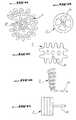
- Figures 2A to 17illustrate the use of a balloon 2 as a means of expansion.
- This balloonwhich is gas and / or liquid tight more or less radiopaque, is equipped with a more or less less rigid inflation 20, intended to pass through the orifice 100 of the textile layer 11.
- the balloon 2can adopt a form chosen from a large number of possible forms, and be more or less spiral shaped developed (Figures 5A to 6B), flowering (Figure 7), star-shaped (figure 8), in air mattress (figure 9), in single torus or multiple (Figure 10), single coil (Figure 11), double serpentine with crossed layers (figure 12), serpentine spiral (figure 13), wheel (figure 14), or grid (figure 15).
- the balloon 2extends mainly in a median plane P, that is to say that the two preferred dimensions which constitute its length and its width forms a median plane P including the balloon 2 deviates little in height.
- the balloon 2can extend further in volume and present, in the deployed configuration, a propeller (Figure 16) or an accordion shape (Figure 17).
- Figures 18 to 27illustrate the use of a wire spring 3 as a means of expansion, this wire 3 being of preferably consisting of a monofilament metal wire.
- the spring wire 3can also adopt a form chosen from a large number of possible shapes, and be notably spiral shaped more or less developed (Figures 18 and 19), flowering or star-shaped ( Figures 20 to 22), in a single coil (Figure 23), in double serpentine with crossed layers (figure 24), serpentine spiral (figure 25), simple eight (figure 26), or eight multiple, for example double eight (figure 27).
- FIGS 28A to 28Dillustrate the use of a hernial plate according to the invention, this plate being in this case supposed to incorporate a balloon 2.
- the plate formed by the pocket 1 and the balloon 2is folded into a ball around the duct of inflation 20 and thrust in the hernial canal K up to enter the latter to its deep orifice.
- balloon 2After complete insertion of plate 1, 2 into the channel K, balloon 2 is filled with air or more liquid or less radiopaque through conduit 20, so that it inflates and spreads pocket 1 between the PR peritoneum and the internal face PA1 of the abdominal wall PA (FIG. 28C).
- balloon 2can be deflated, and removed from pocket 1 and the hernial canal K ( Figure 28D).
- this plateis set up as in the previous case.
- the plate of the inventionmay include, as shown FIGS. 4A and 4B, suture threads 4 secured to the textile layer 11, set in needles 40 each their ends, and allowing to link the pocket 1 to the wall abdominal PA, after deployment of this pocket behind the internal face PA1 of the abdominal wall PA.
Landscapes
- Health & Medical Sciences (AREA)
- Cardiology (AREA)
- Oral & Maxillofacial Surgery (AREA)
- Transplantation (AREA)
- Engineering & Computer Science (AREA)
- Biomedical Technology (AREA)
- Heart & Thoracic Surgery (AREA)
- Vascular Medicine (AREA)
- Life Sciences & Earth Sciences (AREA)
- Animal Behavior & Ethology (AREA)
- General Health & Medical Sciences (AREA)
- Public Health (AREA)
- Veterinary Medicine (AREA)
- Prostheses (AREA)
- Materials For Medical Uses (AREA)
- Aiming, Guidance, Guns With A Light Source, Armor, Camouflage, And Targets (AREA)
- Air Bags (AREA)
Abstract
Description
Translated fromFrenchLa présente invention concerne, de façon générale, ledomaine des implants chirurgicaux.The present invention relates, in general, to thefield of surgical implants.
Plus précisément, l'invention concerne une plaqueherniaire du type de celles qui comprennent une poche forméede première et seconde couches textiles liées l'une à l'autrepar leurs périphéries respectives, et des moyens d'expansionassurant un déploiement de la poche derrière la face interned'une paroi musculaire.More specifically, the invention relates to a platehernial of the type that includes a formed pocketfirst and second textile layers bonded to each otherby their respective peripheries, and means of expansionensuring deployment of the pocket behind the internal faceof a muscle wall.
Une plaque de ce type est décrite dans le document debrevet EP 0 252 607.A plate of this type is described in the document ofEP patent 0 252 607.
L'implant décrit dans ce document antérieur prend laforme d'un coussin rempli de fibres destinées à êtrerésorbées par le corps humain.The implant described in this previous document takes theform of a cushion filled with fibers intended to beabsorbed by the human body.
Non seulement cet implant se trouve ainsi gonflé enpermanence, de sorte que son insertion dans un orificeherniaire est délicate, mais il représente un corps étrangerde volume important que l'organisme du patient dans lequel ilest implanté doit résorber.Not only is this implant thus inflated inpermanently, so that its insertion into an orificehernial is delicate, but it represents a foreign bodyof significant volume than the patient's organism in which itis implanted must resorb.
Dans ce contexte, la présente invention a pour but deproposer une plaque herniaire offrant une grande facilitéd'insertion et perturbant de façon minimale l'organisme danslequel elle est implantée.In this context, the present invention aims tooffer a hernial plate offering great easeinsertion and minimally disrupting the body inwhich it is implanted.
A cette fin, la plaque herniaire de l'invention, parailleurs conforme à la définition générique qu'en donne lepréambule ci-dessus, est essentiellement caractérisée en ceque les moyens d'expansion sont reçus de façon amovible dansla poche, en ce que la première couche textile présente unorifice permettant le retrait des moyens d'expansion hors dela poche après le déploiement de celle-ci, et en ce que lesmoyens d'expansion passent par déformation réversible d'uneconfiguration déployée à une configuration ramassée en boule,ce dont il résulte que la plaque dans son ensemble peut elle-mêmeadopter une configuration en boule pour permettre soninsertion dans le canal herniaire.To this end, the hernial plate of the invention, byelsewhere conforms to the generic definition given by thepreamble above, is essentially characterized in thatthat the expansion means are removably received inthe pocket, in that the first textile layer has aorifice allowing the withdrawal of the expansion means out ofthe pocket after deployment thereof, and in that themeans of expansion pass by reversible deformation of aconfiguration deployed to a configuration collected in a ball,which results in that the whole plate can itselfadopt a ball configuration to allow itsinsertion into the hernial canal.
La seconde couche textile est par exemple conformée endisque.The second textile layer is for example shaped asdisk.
L'orifice peut alors avoir une position centrale parrapport à la poche et la première couche textile peut êtredécoupée en plusieurs secteurs radiaux distribués autour del'orifice et se recouvrant mutuellement. Les secteurs radiauxpeuvent être fixés par un lien coulissant circulaire.The orifice can then have a central position bycompared to the pocket and the first textile layer can becut into several radial sectors distributed aroundthe orifice and overlapping each other. The radial sectorscan be fixed by a circular sliding link.
Dans un premier mode de réalisation possible del'invention, les moyens d'expansion comprennent un ballonnetétanche au gaz et / ou à un liquide éventuellement radio-opaque,ce ballonnet comprenant un conduit plus ou moinsrigide de gonflage, traversant l'orifice de la premièrecouche. Le liquide plus ou moins radio-opaque permet uncontrôle radioscopique du bon positionnement de la plaque.In a first possible embodiment ofthe invention, the expansion means comprise a balloonimpervious to gas and / or possibly radiopaque liquid,this balloon comprising a duct more or lessrigid inflation, crossing the opening of the firstlayer. The more or less radiopaque liquid allows aradioscopic control of the correct positioning of the plate.
Le ballonnet, en configuration déployée, peut s'étendredans un plan médian et être conformé en étoile, en fleur, enspirale, en serpentin, en grille, en matelas, en roue, ou entore simple ou multiple. La matière constituant le ballonnetpeut être plus ou moins élastique ou rigide.The balloon, in the deployed configuration, can extendin a median plane and be shaped like a star, flower,spiral, serpentine, grid, mattress, wheel, orsingle or multiple torus. The material constituting the ballooncan be more or less elastic or rigid.
En variante, ce ballonnet peut aussi s'étendre en volumeet être conformé en hélice ou en accordéon dans saconfiguration déployée.As a variant, this balloon can also extend in volumeand be shaped like a helix or accordion in itsdeployed configuration.
Dans un second mode de réalisation possible del'invention, les moyens d'expansion peuvent comprendre un filressort, par exemple un fil métallique monofilament.In a second possible embodiment ofthe invention, the expansion means may comprise a wirespring, for example a monofilament metal wire.
Ce fil ressort, en configuration déployée, estavantageusement conformé en étoile, en fleur, en spirale, enserpentin, ou en huit simple ou multiple.This spring wire, in the deployed configuration, isadvantageously shaped as a star, in flower, in a spiral, inserpentine, or in single or multiple eight.
Par ailleurs, le fil ressort est de préférence renduextractible de la poche par traction sur un brin du filressort accessible à travers l'orifice.Furthermore, the spring wire is preferably returnedextractable from the pocket by pulling on a strand of wirespring accessible through the hole.
Enfin, quel que soit son mode de réalisation, la plaqueherniaire de l'invention peut comprendre des fils de suturesolidaires de la première couche textile.Finally, whatever its embodiment, the platehernial of the invention may include suturesattached to the first textile layer.
D'autres caractéristiques et avantages de l'inventionressortiront clairement de la description qui en est faiteci-après, à titre indicatif et nullement limitatif, enréférence aux dessins annexés, dans lesquels:
- la Figure 1 est une vue en coupe d'une régionherniaire, susceptible d'être traitée par insertion de laplaque de l'invention;
- la Figure 2A est une vue en coupe d'une plaque conformeà un premier mode de réalisation de l'invention;
- la Figure 2B est une vue de face de la plaque herniaireillustrée à la figure 2A;
- la Figure 3A est une vue en coupe d'une plaque conformeà une variante du premier mode de réalisation de l'invention;
- la Figure 3B est une vue de face agrandie de la plaqueherniaire illustrée à la figure 3A;
- la Figure 4A est une vue en coupe d'une plaquesemblable à celle qu'illustre la figure 2A, équipée de filsde suture traversant une couche de la prothèse et sertis àchaque extrémité dans une aiguille ;,
- la Figure 4B est une vue de face de la plaque herniaireillustrée à la figure 4A;
- la Figure 5A est une vue de face d'un ballonnetutilisable dans une plaque conforme au premier mode deréalisation de l'invention;
- la Figure 5B est une vue de côté du ballonnet illustréà la figure 5A;
- la Figure 6A est une vue de face d'un autre ballonnetutilisable dans une plaque conforme au premier mode deréalisation de l'invention;
- la Figure 6B est une vue de côté du ballonnet illustréà la figure 6A;
- les Figures 7 à 17 sont des vues de face d'autresballonnets utilisables dans une plaque conforme au premiermode de réalisation de l'invention;
- les Figures 18 à 27 sont des vues de face de filsressorts utilisables dans une plaque conforme à un secondmode de réalisation de l'invention;
- les Figures 28A à 28D sont des vues en perspectivereprésentant des phases successives d'insertion, dans uncanal herniaire, d'une plaque conforme au premier mode deréalisation de l'invention; et
- la Figure 29 est une vue en perspective représentantl'extraction d'un fil ressort hors d'une plaque conforme ausecond mode de réalisation de l'invention, déployée derrièreun canal herniaire.
- Figure 1 is a sectional view of a hernial region, capable of being treated by insertion of the plate of the invention;
- Figure 2A is a sectional view of a plate according to a first embodiment of the invention;
- Figure 2B is a front view of the hernial plate illustrated in Figure 2A;
- Figure 3A is a sectional view of a plate according to a variant of the first embodiment of the invention;
- Figure 3B is an enlarged front view of the hernial plate illustrated in Figure 3A;
- FIG. 4A is a sectional view of a plate similar to that illustrated in FIG. 2A, equipped with suture threads passing through a layer of the prosthesis and crimped at each end in a needle;,
- Figure 4B is a front view of the hernial plate illustrated in Figure 4A;
- Figure 5A is a front view of a balloon usable in a plate according to the first embodiment of the invention;
- Figure 5B is a side view of the balloon illustrated in Figure 5A;
- Figure 6A is a front view of another balloon usable in a plate according to the first embodiment of the invention;
- Figure 6B is a side view of the balloon illustrated in Figure 6A;
- Figures 7 to 17 are front views of other balloons usable in a plate according to the first embodiment of the invention;
- Figures 18 to 27 are front views of spring wires used in a plate according to a second embodiment of the invention;
- Figures 28A to 28D are perspective views showing successive phases of insertion, into a hernial canal, of a plate according to the first embodiment of the invention; and
- Figure 29 is a perspective view showing the extraction of a spring wire from a plate according to the second embodiment of the invention, deployed behind a hernial canal.
Comme annoncé précédemment, l'invention concerne uneplaque herniaire, c'est-à-dire une plaque destinée à pallierune faiblesse d'une paroi du corps humain en se substituant àelle pour assurer une fonction de maintien.As previously announced, the invention relates to ahernial plate, i.e. a plate intended to compensatea weakness of a wall of the human body by replacingit to provide a holding function.
La figure 1 représente une hernie de la paroi abdominalePA, cette dernière étant formée de muscle et de graisse.Figure 1 shows a hernia of the abdominal wallPA, the latter being formed of muscle and fat.
Cette pathologie se traduit par la formation d'un canalherniaire K, à travers lequel passent le péritoine PR et desviscères V, qui forment ensemble une excroissance sous lapeau PE.This pathology results in the formation of a canalhernial K, through which pass the peritoneum PR andviscera V, which together form a growth under thePE skin.
La plaque herniaire, qui vient se placer entre la faceinterne PA1 de la paroi abdominale PA et le péritoine PR, aainsi pour rôle, de façon connue en soi, de boucher le canalherniaire K.The hernial plate, which is placed between the faceinternal PA1 of the abdominal wall PA and the peritoneum PR, athus the role, in a manner known per se, of plugging the canalhernial K.
La plaque de l'invention comprend essentiellement unepoche 1, qui est formée de deux couches textiles 11 et 12, etdes moyens d'expansion, tels qu'un ballonnet 2 ou un filressort 3, pour assurer un déploiement de la poche 1 derrièrela face interne PA1 de la paroi abdominale PA.The plate of the invention essentially comprises a
Les couches textiles 11 et 12 sont liées l'une à l'autrepar leurs périphéries respectives 110 et 120.The
Par exemple, les couches textiles 11 et 12 peuvent êtreréunies l'une à l'autre par couture, soudure ou collage (figures 2A et 2B), ou appartenir à une même bande de textile(figures 3A et 3B).For example,
Selon l'invention, les moyens d'expansion, tels que leballonnet 2 ou le fil ressort 3, sont reçus de façon amovibledans la poche 1.According to the invention, the expansion means, such as the
Pour ce faire, la couche textile 11 de la poche 1, quiest destinée à venir sur la face interne PA1 de la paroiabdominale PA, présente un orifice 100 qui permet le retraitde ces moyens d'expansion 2 ou 3 hors de la poche 1, après ledéploiement de celle-ci derrière le canal herniaire K.To do this, the
Par ailleurs, quelle que soit leur forme particulière deréalisation, les moyens d'expansion 2 ou 3 passent pardéformation réversible d'une configuration déployée à uneconfiguration ramassée en boule.Furthermore, whatever their particular form ofembodiment, the expansion means 2 or 3 pass throughreversible deformation of a configuration deployed at aconfiguration picked up in a ball.
Dans ces conditions, la plaque, considérée dans sonensemble, c'est-à-dire comprenant la poche textile 1 et unmoyen d'expansion tel qu'un ballonnet 2 ou un fil ressort 3,peut elle-même adopter une configuration en boule, ce quipermet son insertion aisée dans le canal herniaire K.Under these conditions, the plate, considered in itstogether, that is to say comprising the
Dans le cas général, la couche textile 12, c'est-à-direla couche textile destinée à venir se placer contre lepéritoine PR, peut être conformée en disque, et l'orifice 100adopte de préférence une position centrale par rapport à lapoche 1.In the general case, the
Si les couches 11 et 12 sont formées dans une même bandetextile, comme illustré aux figures 3A et 3B, la couchetextile 11 est avantageusement découpée en plusieurs secteursradiaux tels que 111 à 118, qui sont distribués autour del'orifice 100 et qui se recouvrent mutuellement. Ces secteursradiaux peuvent être fixés par un lien coulissant circulaire,qui en assure la liaison.If
Les figures 2A à 17 illustrent l'utilisation d'unballonnet 2 en tant que moyen d'expansion.Figures 2A to 17 illustrate the use of a
Ce ballonnet, qui est étanche au gaz et / ou à un liquideplus ou moins radio-opaque, est équipé d'un conduit plus ou moins rigide 20 de gonflage, prévu pour traverser l'orifice100 de la couche textile 11.This balloon, which is gas and / or liquid tightmore or less radiopaque, is equipped with a more or lessless
En configuration déployée, le ballonnet 2 peut adopterune forme choisie dans un grand nombre de formes possibles,et être notamment conformé en spirale plus ou moinsdéveloppée (figures 5A à 6B), en fleur (figure 7), en étoile(figure 8), en matelas pneumatique (figure 9), en tore simpleou multiple (figure 10), en serpentin simple (figure 11), enserpentin double à couches croisées (figure 12), en serpentinspiralé (figure 13), en roue (figure 14), ou en grille(figure 15).In the deployed configuration, the
Dans tous les cas cités, le ballonnet 2 s'étendprincipalement dans un plan médian P, c'est-à-dire que lesdeux dimensions privilégiées qui constituent sa longueur etsa largeur forment un plan médian P dont le ballonnet 2s'écarte peu en hauteur.In all the cases cited, the
Néanmoins, le ballonnet 2 peut s'étendre davantage envolume et présenter, en configuration déployée, une forme enhélice (figure 16) ou une forme en accordéon (figure 17).However, the
Les figures 18 à 27 illustrent l'utilisation d'un filressort 3 en tant que moyen d'expansion, ce fil 3 étant depréférence constitué par un fil métallique monofilament.Figures 18 to 27 illustrate the use of a
En configuration déployée, le fil ressort 3 peut luiaussi adopter une forme choisie dans un grand nombre deformes possibles, et être notamment conformé en spirale plusou moins développée (figures 18 et 19), en fleur ou en étoile(figures 20 à 22), en serpentin simple (figure 23), enserpentin double à couches croisées (figure 24), en serpentinspiralé (figure 25), en huit simple (figure 26), ou en huitmultiple, par exemple en double huit (figure 27).In the deployed configuration, the
Les figures 28A à 28D illustrent l'utilisation d'uneplaque herniaire conforme à l'invention, cette plaque étanten l'occurrence supposée incorporer un ballonnet 2.Figures 28A to 28D illustrate the use of ahernial plate according to the invention, this plate beingin this case supposed to incorporate a
Tout d'abord (figure 28A), la plaque formée par la poche1 et le ballonnet 2 est repliée en boule autour du conduit de gonflage 20 et poussée dans le canal herniaire K jusqu'às'introduire dans ce dernier jusqu'à son orifice profond.First (Figure 28A), the plate formed by the
Après introduction complète de la plaque 1, 2 dans lecanal K, le ballonnet 2 est rempli d'air ou d'un liquide plusou moins radio-opaque à travers le conduit 20, de sorte qu'ilse gonfle et qu'il étale la poche 1 entre le péritoine PR etla face interne PA1 de la paroi abdominale PA (figure 28C).After complete insertion of
Une fois que la poche 1 est en place, le ballonnet 2 peutêtre dégonflé, et extrait de la poche 1 et du canal herniaireK (figure 28D).Once
Dans le cas où la plaque de l'invention utilise un filressort 3 en tant que moyen d'expansion, cette plaque estmise en place comme dans le cas précédent.In the case where the plate of the invention uses a
En revanche, l'extraction du fil ressort 3 après la posede la poche 1 peut justifier de prévoir que ce fil 3 présenteun brin 30 accessible au travers de l'orifice 100 de lacouche textile 11, de manière que ce fil 3 puisse êtreextrait de la poche 1 par traction sur ce brin 30.On the other hand, the extraction of the wire comes out 3 after
Dans tous les cas, et en particulier dans ce dernier cas,la plaque de l'invention peut comprendre, comme le montrentles figures 4A et 4B, des fils de suture 4 solidaires de lacouche textile 11, sertis dans des aiguilles 40 à chacune deleurs extrémités, et permettant de lier la poche 1 à la paroiabdominale PA, après déploiement de cette poche derrière laface interne PA1 de la paroi abdominale PA.In all cases, and in particular in the latter case,the plate of the invention may include, as shownFIGS. 4A and 4B, suture threads 4 secured to the
Claims (13)
Translated fromFrenchApplications Claiming Priority (2)
| Application Number | Priority Date | Filing Date | Title |
|---|---|---|---|
| FR0201774AFR2835737B1 (en) | 2002-02-13 | 2002-02-13 | HERMAL PLATE WITH NON-PERMANENT DEPLOYMENT MEMBER |
| FR0201774 | 2002-02-13 |
Publications (2)
| Publication Number | Publication Date |
|---|---|
| EP1336391A1true EP1336391A1 (en) | 2003-08-20 |
| EP1336391B1 EP1336391B1 (en) | 2011-12-14 |
Family
ID=27620162
Family Applications (1)
| Application Number | Title | Priority Date | Filing Date |
|---|---|---|---|
| EP03290346AExpired - LifetimeEP1336391B1 (en) | 2002-02-13 | 2003-02-12 | Hernia plate for non permanent deploying |
Country Status (5)
| Country | Link |
|---|---|
| EP (1) | EP1336391B1 (en) |
| JP (1) | JP2004033729A (en) |
| AT (1) | ATE536832T1 (en) |
| ES (1) | ES2385308T3 (en) |
| FR (1) | FR2835737B1 (en) |
Cited By (18)
| Publication number | Priority date | Publication date | Assignee | Title |
|---|---|---|---|---|
| WO2007034145A3 (en)* | 2005-09-19 | 2007-07-12 | Evexar Medical Ltd | Abdominal reinforcement device |
| WO2009010951A1 (en) | 2007-06-18 | 2009-01-22 | Magen Medical Solutions Ltd | Temporary implantable medical device |
| WO2010031967A1 (en)* | 2008-09-18 | 2010-03-25 | Sofradim Production | Surgical instrument for deploying a prosthesis |
| FR2948011A1 (en)* | 2009-07-20 | 2011-01-21 | Jean Claude Sgro | Surgical treatment device for e.g. umbilical hernia of abdominal wall, has prosthesis fixed to arms by points that follow displacement of arms during passage of arms from folded state to unfolded state |
| EP2363095A2 (en) | 2008-05-07 | 2011-09-07 | Davol Inc. | Method and apparatus for repairing a hernia |
| US8500762B2 (en) | 2007-10-17 | 2013-08-06 | Davol, Inc. (a C.R. Bard Company) | Fixating means between a mesh and mesh deployment means especially useful for hernia repair surgeries and methods thereof |
| US20130218179A1 (en)* | 2006-11-27 | 2013-08-22 | Davol, Inc. (a C.R. Bard Company) | Device especially useful for hernia repair surgeries and methods thereof |
| US8920370B2 (en) | 2004-10-14 | 2014-12-30 | Davol, Inc. (a C.R. Bard Company) | Hernia repair device |
| WO2015011417A1 (en)* | 2013-07-25 | 2015-01-29 | Cousin Biotech | Implantable prosthesis |
| EP2244665A4 (en)* | 2008-01-29 | 2015-05-06 | Insightra Medical Inc | FORTIFIED MESH FOR TISSUE REPAIR |
| US9504548B2 (en) | 2008-11-21 | 2016-11-29 | C.R. Bard, Inc. | Soft tissue repair prosthesis, expandable device, and method of soft tissue repair |
| US9808331B2 (en) | 2010-10-05 | 2017-11-07 | C.R. Bard, Inc. | Soft tissue repair prosthesis and expandable device |
| US9937028B2 (en) | 2013-01-29 | 2018-04-10 | Bard Shannon Limited | Muscle wall defect prosthesis and deployment system |
| US10105205B2 (en) | 2014-12-02 | 2018-10-23 | Bard Shannon Limited | Muscle wall defect prosthesis and deployment system |
| US10172700B2 (en) | 2014-12-01 | 2019-01-08 | C.R. Bard, Inc. | Prosthesis for repairing a hernia defect |
| US10335258B2 (en) | 2015-12-28 | 2019-07-02 | C.R. Bard, Inc. | Prosthesis for repairing a hernia defect |
| US10449027B2 (en) | 2015-12-28 | 2019-10-22 | C.R. Bard, Inc. | Deployment device for a soft tissue repair prosthesis |
| CN114126508A (en)* | 2019-09-02 | 2022-03-01 | 金炯勋 | Arthroscopic Bleeding Control Device |
Families Citing this family (2)
| Publication number | Priority date | Publication date | Assignee | Title |
|---|---|---|---|---|
| CA2940476C (en) | 2014-03-06 | 2019-05-07 | C.R. Bard, Inc. | Hernia repair patch |
| US10898602B2 (en)* | 2019-01-29 | 2021-01-26 | James Allen Kodak | Alcohol vapor deodorization system |
Citations (6)
| Publication number | Priority date | Publication date | Assignee | Title |
|---|---|---|---|---|
| US5122155A (en)* | 1990-10-11 | 1992-06-16 | Eberbach Mark A | Hernia repair apparatus and method of use |
| US5176692A (en)* | 1991-12-09 | 1993-01-05 | Wilk Peter J | Method and surgical instrument for repairing hernia |
| EP0557964A1 (en)* | 1992-02-24 | 1993-09-01 | United States Surgical Corporation | Articulating mesh deployment apparatus |
| US5258000A (en)* | 1991-11-25 | 1993-11-02 | Cook Incorporated | Tissue aperture repair device |
| US5366460A (en)* | 1990-10-11 | 1994-11-22 | Cook Incorporated | Apparatus and method for laparoscope hernia repair |
| US5540711A (en)* | 1992-06-02 | 1996-07-30 | General Surgical Innovations, Inc. | Apparatus and method for developing an anatomic space for laparoscopic procedures with laparoscopic visualization |
- 2002
- 2002-02-13FRFR0201774Apatent/FR2835737B1/ennot_activeExpired - Lifetime
- 2003
- 2003-02-12EPEP03290346Apatent/EP1336391B1/ennot_activeExpired - Lifetime
- 2003-02-12ESES03290346Tpatent/ES2385308T3/ennot_activeExpired - Lifetime
- 2003-02-12ATAT03290346Tpatent/ATE536832T1/enactive
- 2003-02-13JPJP2003035589Apatent/JP2004033729A/enactivePending
Patent Citations (6)
| Publication number | Priority date | Publication date | Assignee | Title |
|---|---|---|---|---|
| US5122155A (en)* | 1990-10-11 | 1992-06-16 | Eberbach Mark A | Hernia repair apparatus and method of use |
| US5366460A (en)* | 1990-10-11 | 1994-11-22 | Cook Incorporated | Apparatus and method for laparoscope hernia repair |
| US5258000A (en)* | 1991-11-25 | 1993-11-02 | Cook Incorporated | Tissue aperture repair device |
| US5176692A (en)* | 1991-12-09 | 1993-01-05 | Wilk Peter J | Method and surgical instrument for repairing hernia |
| EP0557964A1 (en)* | 1992-02-24 | 1993-09-01 | United States Surgical Corporation | Articulating mesh deployment apparatus |
| US5540711A (en)* | 1992-06-02 | 1996-07-30 | General Surgical Innovations, Inc. | Apparatus and method for developing an anatomic space for laparoscopic procedures with laparoscopic visualization |
Cited By (46)
| Publication number | Priority date | Publication date | Assignee | Title |
|---|---|---|---|---|
| US8920370B2 (en) | 2004-10-14 | 2014-12-30 | Davol, Inc. (a C.R. Bard Company) | Hernia repair device |
| US9687332B2 (en) | 2004-10-14 | 2017-06-27 | Davol, Inc. | Hernia repair device |
| WO2007034145A3 (en)* | 2005-09-19 | 2007-07-12 | Evexar Medical Ltd | Abdominal reinforcement device |
| US9993324B2 (en) | 2005-10-09 | 2018-06-12 | Davol Inc. | Method and apparatus for repairing a hernia |
| US9861462B2 (en)* | 2006-11-27 | 2018-01-09 | Davol, Inc. (a C.R. Bard Company) | Device especially useful for hernia repair surgeries and methods thereof |
| US12161542B2 (en) | 2006-11-27 | 2024-12-10 | Davol Inc. | Device especially useful for hernia repair surgeries and methods thereof |
| US20130218179A1 (en)* | 2006-11-27 | 2013-08-22 | Davol, Inc. (a C.R. Bard Company) | Device especially useful for hernia repair surgeries and methods thereof |
| US10898309B2 (en) | 2006-11-27 | 2021-01-26 | Davol Inc. | Device especially useful for hernia repair surgeries and methods thereof |
| WO2009010951A1 (en) | 2007-06-18 | 2009-01-22 | Magen Medical Solutions Ltd | Temporary implantable medical device |
| US8500762B2 (en) | 2007-10-17 | 2013-08-06 | Davol, Inc. (a C.R. Bard Company) | Fixating means between a mesh and mesh deployment means especially useful for hernia repair surgeries and methods thereof |
| US10751156B2 (en) | 2007-10-17 | 2020-08-25 | Davol Inc. | Fixating means between a mesh and mesh deployment means especially useful for hernia repair surgeries and methods thereof |
| US11806223B2 (en) | 2007-10-17 | 2023-11-07 | Davol Inc. | Fixating means between a mesh and mesh deployment means especially useful for hernia repair surgeries and methods thereof |
| US9642689B2 (en) | 2007-10-17 | 2017-05-09 | Davol, Inc. | Fixating means between a mesh and mesh deployment means especially useful for hernia repair surgeries and methods thereof |
| EP2244665A4 (en)* | 2008-01-29 | 2015-05-06 | Insightra Medical Inc | FORTIFIED MESH FOR TISSUE REPAIR |
| US10159553B2 (en) | 2008-01-29 | 2018-12-25 | Insightra Medical, Inc. | Fortified mesh for tissue repair |
| US8920445B2 (en) | 2008-05-07 | 2014-12-30 | Davol, Inc. | Method and apparatus for repairing a hernia |
| US10864068B2 (en) | 2008-05-07 | 2020-12-15 | Davol Inc. | Method and apparatus for repairing a hernia |
| EP2363095A2 (en) | 2008-05-07 | 2011-09-07 | Davol Inc. | Method and apparatus for repairing a hernia |
| US20180368962A1 (en)* | 2008-05-07 | 2018-12-27 | Davol Inc. | Method and apparatus for repairing a hernia |
| US12239519B2 (en) | 2008-05-07 | 2025-03-04 | Davol Inc. | Method and apparatus for repairing a hernia |
| US10687929B2 (en) | 2008-09-18 | 2020-06-23 | Sofradim Production | Surgical instrument for deploying a prosthesis |
| AU2009294426B2 (en)* | 2008-09-18 | 2015-02-05 | Sofradim Production | Surgical instrument for deploying a prosthesis |
| US8808315B2 (en) | 2008-09-18 | 2014-08-19 | Sofradim Production | Surgical instrument for deploying a prosthesis |
| WO2010031967A1 (en)* | 2008-09-18 | 2010-03-25 | Sofradim Production | Surgical instrument for deploying a prosthesis |
| US9504548B2 (en) | 2008-11-21 | 2016-11-29 | C.R. Bard, Inc. | Soft tissue repair prosthesis, expandable device, and method of soft tissue repair |
| US10548703B2 (en) | 2008-11-21 | 2020-02-04 | C.R. Bard, Inc. | Soft tissue repair prosthesis, expandable device, and method of soft tissue repair |
| FR2948011A1 (en)* | 2009-07-20 | 2011-01-21 | Jean Claude Sgro | Surgical treatment device for e.g. umbilical hernia of abdominal wall, has prosthesis fixed to arms by points that follow displacement of arms during passage of arms from folded state to unfolded state |
| US10166093B2 (en) | 2010-10-05 | 2019-01-01 | C.R. Bard, Inc. | Soft tissue repair prosthesis and expandable device |
| US9808331B2 (en) | 2010-10-05 | 2017-11-07 | C.R. Bard, Inc. | Soft tissue repair prosthesis and expandable device |
| US10905537B2 (en) | 2010-10-05 | 2021-02-02 | C.R. Bard, Inc. | Soft tissue repair prosthesis and expandable device |
| US9937028B2 (en) | 2013-01-29 | 2018-04-10 | Bard Shannon Limited | Muscle wall defect prosthesis and deployment system |
| US10751157B2 (en) | 2013-01-29 | 2020-08-25 | Bard Shannon Limited | Muscle wall defect prosthesis and deployment system |
| WO2015011417A1 (en)* | 2013-07-25 | 2015-01-29 | Cousin Biotech | Implantable prosthesis |
| FR3008884A1 (en)* | 2013-07-25 | 2015-01-30 | Cousin Biotech | IMPLANTABLE PROSTHESIS |
| US10172700B2 (en) | 2014-12-01 | 2019-01-08 | C.R. Bard, Inc. | Prosthesis for repairing a hernia defect |
| US10918472B2 (en) | 2014-12-02 | 2021-02-16 | Bard Shannon Limited | Muscle wall defect prosthesis and deployment system |
| US10105205B2 (en) | 2014-12-02 | 2018-10-23 | Bard Shannon Limited | Muscle wall defect prosthesis and deployment system |
| US10675136B2 (en) | 2015-12-28 | 2020-06-09 | C.R. Bard, Inc. | Deployment device for a soft tissue repair prosthesis |
| US10675135B2 (en) | 2015-12-28 | 2020-06-09 | C.R. Bard, Inc. | Deployment device for a soft tissue repair prosthesis |
| US10646322B2 (en) | 2015-12-28 | 2020-05-12 | C.R. Bard, Inc. | Deployment device for a soft tissue repair prosthesis |
| US11464615B2 (en) | 2015-12-28 | 2022-10-11 | C.R. Bard, Inc. | Deployment device for a soft tissue repair prosthesis |
| US10449027B2 (en) | 2015-12-28 | 2019-10-22 | C.R. Bard, Inc. | Deployment device for a soft tissue repair prosthesis |
| US12102520B2 (en) | 2015-12-28 | 2024-10-01 | C.R. Bard, Inc. | Deployment device for a soft tissue repair prosthesis |
| US10350046B2 (en) | 2015-12-28 | 2019-07-16 | C.R. Bard, Inc. | Prothesis for repairing a hernia defect |
| US10335258B2 (en) | 2015-12-28 | 2019-07-02 | C.R. Bard, Inc. | Prosthesis for repairing a hernia defect |
| CN114126508A (en)* | 2019-09-02 | 2022-03-01 | 金炯勋 | Arthroscopic Bleeding Control Device |
Also Published As
| Publication number | Publication date |
|---|---|
| FR2835737A1 (en) | 2003-08-15 |
| ATE536832T1 (en) | 2011-12-15 |
| FR2835737B1 (en) | 2004-12-10 |
| JP2004033729A (en) | 2004-02-05 |
| EP1336391B1 (en) | 2011-12-14 |
| ES2385308T3 (en) | 2012-07-20 |
Similar Documents
| Publication | Publication Date | Title |
|---|---|---|
| EP1336391A1 (en) | Hernia plate for non permanent deploying | |
| EP1103233B1 (en) | Monobloc blood filter production method | |
| EP2000116B1 (en) | Kit designed to be implanted in a blood vessel | |
| EP1024764B1 (en) | Prosthetic implant for obstructing an anatomical duct, and obstructing assembly comprising same | |
| EP0107231B1 (en) | Partial occlusive device for blood vessels, in particular the vena cava | |
| EP0639956B1 (en) | Device for stretching live tissue | |
| CA2424319C (en) | Vascular occlusion device, apparatus and method for using same | |
| EP1401359B1 (en) | Kit enabling a prosthetic valve to be placed in a body enabling a prosthetic valve to be put into place in a duct in the body | |
| EP0836838B1 (en) | Anatomical prosthesis for inguinal hernia repair via open of laparoscopic surgery | |
| EP0605276B1 (en) | Device for selective use as a temporary blood-filter | |
| EP2334256B1 (en) | Surgical instrument for deploying a prosthesis | |
| FR2712486A1 (en) | Intervertebral prosthesis | |
| FR2694687A1 (en) | Intra-vascular prosthesis for blood filtration and clot prevention - comprises series of flexible threads formed into arrangement of shaped loops, secured to distal end of tubular support portion | |
| FR2682284A1 (en) | Mammary prosthesis | |
| EP3863561B1 (en) | Stent-type aortic implant and assembly formed by two such implants | |
| WO1996041588A1 (en) | Internal prosthesis consisting of a fabric or other substrate, and apparatus for celioscopically inserting same | |
| EP1836994A1 (en) | Surgical device for the formation by the practitioner of at least one implant | |
| EP0781531A1 (en) | Process and apparatus for facilitating bone growth, in particular for dental and maxillo-facial surgery and apparatus for carrying out the process | |
| FR2778554A1 (en) | Shaped bandage for surgical implant | |
| EP0299002B1 (en) | Tissue expansion prosthesis | |
| WO2000071062A1 (en) | Bi-canalicular probe for the treatment of lacrimation of the eye | |
| EP2379005B1 (en) | Implantable device and prosthetic implant including at least one such device | |
| FR2801194A1 (en) | An implant for restoring articulated movement to the thumb comprises a rigid barrel shaped core of polyethylene and a fibrous polyester envelope, both non resorbable, and attachment sutures. | |
| EP2127614B1 (en) | Anchoring and guiding device, manufacturing method and associated implant | |
| EP2451362B1 (en) | Implantable device for bringing together anatomical structures, in particular in hiatal hernia treatment |
Legal Events
| Date | Code | Title | Description |
|---|---|---|---|
| PUAI | Public reference made under article 153(3) epc to a published international application that has entered the european phase | Free format text:ORIGINAL CODE: 0009012 | |
| AK | Designated contracting states | Designated state(s):AT BE BG CH CY CZ DE DK EE ES FI FR GB GR HU IE IT LI LU MC NL PT SE SI SK TR | |
| AX | Request for extension of the european patent | Extension state:AL LT LV MK RO | |
| 17P | Request for examination filed | Effective date:20040212 | |
| AKX | Designation fees paid | Designated state(s):AT BE BG CH CY CZ DE DK EE ES FI FR GB GR HU IE IT LI LU MC NL PT SE SI SK TR | |
| 17Q | First examination report despatched | Effective date:20100930 | |
| GRAP | Despatch of communication of intention to grant a patent | Free format text:ORIGINAL CODE: EPIDOSNIGR1 | |
| GRAS | Grant fee paid | Free format text:ORIGINAL CODE: EPIDOSNIGR3 | |
| GRAA | (expected) grant | Free format text:ORIGINAL CODE: 0009210 | |
| AK | Designated contracting states | Kind code of ref document:B1 Designated state(s):AT BE BG CH CY CZ DE DK EE ES FI FR GB GR HU IE IT LI LU MC NL PT SE SI SK TR | |
| REG | Reference to a national code | Ref country code:GB Ref legal event code:FG4D Free format text:NOT ENGLISH | |
| REG | Reference to a national code | Ref country code:CH Ref legal event code:EP | |
| REG | Reference to a national code | Ref country code:IE Ref legal event code:FG4D | |
| REG | Reference to a national code | Ref country code:DE Ref legal event code:R096 Ref document number:60339389 Country of ref document:DE Effective date:20120209 | |
| REG | Reference to a national code | Ref country code:NL Ref legal event code:VDEP Effective date:20111214 | |
| PG25 | Lapsed in a contracting state [announced via postgrant information from national office to epo] | Ref country code:NL Free format text:LAPSE BECAUSE OF FAILURE TO SUBMIT A TRANSLATION OF THE DESCRIPTION OR TO PAY THE FEE WITHIN THE PRESCRIBED TIME-LIMIT Effective date:20111214 Ref country code:SE Free format text:LAPSE BECAUSE OF FAILURE TO SUBMIT A TRANSLATION OF THE DESCRIPTION OR TO PAY THE FEE WITHIN THE PRESCRIBED TIME-LIMIT Effective date:20111214 Ref country code:GR Free format text:LAPSE BECAUSE OF FAILURE TO SUBMIT A TRANSLATION OF THE DESCRIPTION OR TO PAY THE FEE WITHIN THE PRESCRIBED TIME-LIMIT Effective date:20120315 Ref country code:SI Free format text:LAPSE BECAUSE OF FAILURE TO SUBMIT A TRANSLATION OF THE DESCRIPTION OR TO PAY THE FEE WITHIN THE PRESCRIBED TIME-LIMIT Effective date:20111214 | |
| PG25 | Lapsed in a contracting state [announced via postgrant information from national office to epo] | Ref country code:CY Free format text:LAPSE BECAUSE OF FAILURE TO SUBMIT A TRANSLATION OF THE DESCRIPTION OR TO PAY THE FEE WITHIN THE PRESCRIBED TIME-LIMIT Effective date:20111214 | |
| REG | Reference to a national code | Ref country code:IE Ref legal event code:FD4D | |
| REG | Reference to a national code | Ref country code:ES Ref legal event code:FG2A Ref document number:2385308 Country of ref document:ES Kind code of ref document:T3 Effective date:20120720 Ref country code:ES Ref legal event code:PC2A Owner name:CABANIOLS, NICOLAS MORAD Effective date:20120710 | |
| PG25 | Lapsed in a contracting state [announced via postgrant information from national office to epo] | Ref country code:CZ Free format text:LAPSE BECAUSE OF FAILURE TO SUBMIT A TRANSLATION OF THE DESCRIPTION OR TO PAY THE FEE WITHIN THE PRESCRIBED TIME-LIMIT Effective date:20111214 Ref country code:SK Free format text:LAPSE BECAUSE OF FAILURE TO SUBMIT A TRANSLATION OF THE DESCRIPTION OR TO PAY THE FEE WITHIN THE PRESCRIBED TIME-LIMIT Effective date:20111214 Ref country code:BG Free format text:LAPSE BECAUSE OF FAILURE TO SUBMIT A TRANSLATION OF THE DESCRIPTION OR TO PAY THE FEE WITHIN THE PRESCRIBED TIME-LIMIT Effective date:20120314 Ref country code:IE Free format text:LAPSE BECAUSE OF FAILURE TO SUBMIT A TRANSLATION OF THE DESCRIPTION OR TO PAY THE FEE WITHIN THE PRESCRIBED TIME-LIMIT Effective date:20111214 Ref country code:EE Free format text:LAPSE BECAUSE OF FAILURE TO SUBMIT A TRANSLATION OF THE DESCRIPTION OR TO PAY THE FEE WITHIN THE PRESCRIBED TIME-LIMIT Effective date:20111214 | |
| BERE | Be: lapsed | Owner name:COUSIN BIOTECH Effective date:20120228 Owner name:CABANIOLS, HENRI Effective date:20120228 | |
| PG25 | Lapsed in a contracting state [announced via postgrant information from national office to epo] | Ref country code:PT Free format text:LAPSE BECAUSE OF FAILURE TO SUBMIT A TRANSLATION OF THE DESCRIPTION OR TO PAY THE FEE WITHIN THE PRESCRIBED TIME-LIMIT Effective date:20120416 | |
| REG | Reference to a national code | Ref country code:AT Ref legal event code:MK05 Ref document number:536832 Country of ref document:AT Kind code of ref document:T Effective date:20111214 | |
| PG25 | Lapsed in a contracting state [announced via postgrant information from national office to epo] | Ref country code:MC Free format text:LAPSE BECAUSE OF NON-PAYMENT OF DUE FEES Effective date:20120229 | |
| REG | Reference to a national code | Ref country code:CH Ref legal event code:PL | |
| PLBE | No opposition filed within time limit | Free format text:ORIGINAL CODE: 0009261 | |
| STAA | Information on the status of an ep patent application or granted ep patent | Free format text:STATUS: NO OPPOSITION FILED WITHIN TIME LIMIT | |
| PG25 | Lapsed in a contracting state [announced via postgrant information from national office to epo] | Ref country code:LI Free format text:LAPSE BECAUSE OF NON-PAYMENT OF DUE FEES Effective date:20120229 Ref country code:DK Free format text:LAPSE BECAUSE OF FAILURE TO SUBMIT A TRANSLATION OF THE DESCRIPTION OR TO PAY THE FEE WITHIN THE PRESCRIBED TIME-LIMIT Effective date:20111214 Ref country code:CH Free format text:LAPSE BECAUSE OF NON-PAYMENT OF DUE FEES Effective date:20120229 | |
| 26N | No opposition filed | Effective date:20120917 | |
| PG25 | Lapsed in a contracting state [announced via postgrant information from national office to epo] | Ref country code:BE Free format text:LAPSE BECAUSE OF NON-PAYMENT OF DUE FEES Effective date:20120228 | |
| REG | Reference to a national code | Ref country code:DE Ref legal event code:R097 Ref document number:60339389 Country of ref document:DE Effective date:20120917 | |
| PG25 | Lapsed in a contracting state [announced via postgrant information from national office to epo] | Ref country code:AT Free format text:LAPSE BECAUSE OF FAILURE TO SUBMIT A TRANSLATION OF THE DESCRIPTION OR TO PAY THE FEE WITHIN THE PRESCRIBED TIME-LIMIT Effective date:20111214 | |
| PG25 | Lapsed in a contracting state [announced via postgrant information from national office to epo] | Ref country code:FI Free format text:LAPSE BECAUSE OF FAILURE TO SUBMIT A TRANSLATION OF THE DESCRIPTION OR TO PAY THE FEE WITHIN THE PRESCRIBED TIME-LIMIT Effective date:20111214 | |
| PG25 | Lapsed in a contracting state [announced via postgrant information from national office to epo] | Ref country code:TR Free format text:LAPSE BECAUSE OF FAILURE TO SUBMIT A TRANSLATION OF THE DESCRIPTION OR TO PAY THE FEE WITHIN THE PRESCRIBED TIME-LIMIT Effective date:20111214 | |
| PG25 | Lapsed in a contracting state [announced via postgrant information from national office to epo] | Ref country code:LU Free format text:LAPSE BECAUSE OF NON-PAYMENT OF DUE FEES Effective date:20120212 | |
| PG25 | Lapsed in a contracting state [announced via postgrant information from national office to epo] | Ref country code:HU Free format text:LAPSE BECAUSE OF FAILURE TO SUBMIT A TRANSLATION OF THE DESCRIPTION OR TO PAY THE FEE WITHIN THE PRESCRIBED TIME-LIMIT Effective date:20030212 | |
| REG | Reference to a national code | Ref country code:FR Ref legal event code:PLFP Year of fee payment:14 | |
| REG | Reference to a national code | Ref country code:FR Ref legal event code:PLFP Year of fee payment:15 | |
| REG | Reference to a national code | Ref country code:DE Ref legal event code:R082 Ref document number:60339389 Country of ref document:DE Representative=s name:GEITZ TRUCKENMUELLER LUCHT CHRIST PATENTANWAEL, DE | |
| REG | Reference to a national code | Ref country code:FR Ref legal event code:PLFP Year of fee payment:16 | |
| PGFP | Annual fee paid to national office [announced via postgrant information from national office to epo] | Ref country code:IT Payment date:20190208 Year of fee payment:17 Ref country code:ES Payment date:20190321 Year of fee payment:17 Ref country code:DE Payment date:20190211 Year of fee payment:17 Ref country code:GB Payment date:20190215 Year of fee payment:17 | |
| REG | Reference to a national code | Ref country code:DE Ref legal event code:R082 Ref document number:60339389 Country of ref document:DE Representative=s name:GEITZ TRUCKENMUELLER LUCHT CHRIST PATENTANWAEL, DE | |
| REG | Reference to a national code | Ref country code:DE Ref legal event code:R119 Ref document number:60339389 Country of ref document:DE | |
| GBPC | Gb: european patent ceased through non-payment of renewal fee | Effective date:20200212 | |
| PG25 | Lapsed in a contracting state [announced via postgrant information from national office to epo] | Ref country code:DE Free format text:LAPSE BECAUSE OF NON-PAYMENT OF DUE FEES Effective date:20200901 Ref country code:GB Free format text:LAPSE BECAUSE OF NON-PAYMENT OF DUE FEES Effective date:20200212 | |
| PG25 | Lapsed in a contracting state [announced via postgrant information from national office to epo] | Ref country code:ES Free format text:LAPSE BECAUSE OF NON-PAYMENT OF DUE FEES Effective date:20200213 | |
| PG25 | Lapsed in a contracting state [announced via postgrant information from national office to epo] | Ref country code:IT Free format text:LAPSE BECAUSE OF NON-PAYMENT OF DUE FEES Effective date:20200212 | |
| PGFP | Annual fee paid to national office [announced via postgrant information from national office to epo] | Ref country code:FR Payment date:20220222 Year of fee payment:20 |