EP1336375B1 - System for painless blood sampling - Google Patents
System for painless blood samplingDownload PDFInfo
- Publication number
- EP1336375B1 EP1336375B1EP03003032AEP03003032AEP1336375B1EP 1336375 B1EP1336375 B1EP 1336375B1EP 03003032 AEP03003032 AEP 03003032AEP 03003032 AEP03003032 AEP 03003032AEP 1336375 B1EP1336375 B1EP 1336375B1
- Authority
- EP
- European Patent Office
- Prior art keywords
- lancet
- impulse
- housing
- contact surface
- tip
- Prior art date
- Legal status (The legal status is an assumption and is not a legal conclusion. Google has not performed a legal analysis and makes no representation as to the accuracy of the status listed.)
- Expired - Lifetime
Links
- 238000010241blood samplingMethods0.000titledescription7
- 239000008280bloodSubstances0.000claimsdescription44
- 210000004369bloodAnatomy0.000claimsdescription44
- 208000002193PainDiseases0.000claimsdescription21
- 230000036407painEffects0.000claimsdescription17
- 230000008058pain sensationEffects0.000claimsdescription7
- 230000001360synchronised effectEffects0.000claims1
- 230000001133accelerationEffects0.000description15
- 230000007246mechanismEffects0.000description6
- 206010003402Arthropod stingDiseases0.000description5
- 238000010168coupling processMethods0.000description5
- 210000000412mechanoreceptorAnatomy0.000description5
- 108091008704mechanoreceptorsProteins0.000description5
- 210000004126nerve fiberAnatomy0.000description5
- 210000000929nociceptorAnatomy0.000description5
- 230000035515penetrationEffects0.000description5
- 230000008878couplingEffects0.000description4
- 238000005859coupling reactionMethods0.000description4
- 108091008700nociceptorsProteins0.000description4
- 230000001960triggered effectEffects0.000description4
- 238000004458analytical methodMethods0.000description3
- 230000005540biological transmissionEffects0.000description3
- 230000000694effectsEffects0.000description3
- 230000002349favourable effectEffects0.000description3
- 230000009467reductionEffects0.000description3
- 230000001105regulatory effectEffects0.000description3
- 230000035939shockEffects0.000description3
- WQZGKKKJIJFFOK-GASJEMHNSA-NGlucoseNatural productsOC[C@H]1OC(O)[C@H](O)[C@@H](O)[C@@H]1OWQZGKKKJIJFFOK-GASJEMHNSA-N0.000description2
- 208000027418Wounds and injuryDiseases0.000description2
- 230000004913activationEffects0.000description2
- 210000001124body fluidAnatomy0.000description2
- 239000010839body fluidSubstances0.000description2
- 238000006243chemical reactionMethods0.000description2
- 239000000835fiberSubstances0.000description2
- 239000008103glucoseSubstances0.000description2
- 230000001788irregularEffects0.000description2
- 230000000873masking effectEffects0.000description2
- 238000005259measurementMethods0.000description2
- 238000000034methodMethods0.000description2
- 210000005036nerveAnatomy0.000description2
- 108020003175receptorsProteins0.000description2
- 230000004936stimulating effectEffects0.000description2
- 230000002123temporal effectEffects0.000description2
- 238000012360testing methodMethods0.000description2
- 229910000831SteelInorganic materials0.000description1
- 239000011324beadSubstances0.000description1
- 238000005452bendingMethods0.000description1
- 230000008901benefitEffects0.000description1
- 210000004556brainAnatomy0.000description1
- 239000000919ceramicSubstances0.000description1
- 230000008859changeEffects0.000description1
- 230000000052comparative effectEffects0.000description1
- 238000011109contaminationMethods0.000description1
- 206010012601diabetes mellitusDiseases0.000description1
- 239000010432diamondSubstances0.000description1
- 201000010099diseaseDiseases0.000description1
- 208000037265diseases, disorders, signs and symptomsDiseases0.000description1
- 238000006073displacement reactionMethods0.000description1
- 238000002474experimental methodMethods0.000description1
- 230000001976improved effectEffects0.000description1
- 230000036540impulse transmissionEffects0.000description1
- 238000011835investigationMethods0.000description1
- 230000007774longtermEffects0.000description1
- 238000004519manufacturing processMethods0.000description1
- 239000000463materialSubstances0.000description1
- 229910052751metalInorganic materials0.000description1
- 239000002184metalSubstances0.000description1
- 150000002739metalsChemical class0.000description1
- 238000012544monitoring processMethods0.000description1
- 230000037324pain perceptionEffects0.000description1
- 238000003825pressingMethods0.000description1
- 230000008569processEffects0.000description1
- 230000002040relaxant effectEffects0.000description1
- 230000000284resting effectEffects0.000description1
- 238000007789sealingMethods0.000description1
- 208000037921secondary diseaseDiseases0.000description1
- 229910052710siliconInorganic materials0.000description1
- 239000010703siliconSubstances0.000description1
- 239000007787solidSubstances0.000description1
- 210000000278spinal cordAnatomy0.000description1
- 229910001220stainless steelInorganic materials0.000description1
- 239000010959steelSubstances0.000description1
- 230000000638stimulationEffects0.000description1
Images


Classifications
- A—HUMAN NECESSITIES
- A61—MEDICAL OR VETERINARY SCIENCE; HYGIENE
- A61B—DIAGNOSIS; SURGERY; IDENTIFICATION
- A61B5/00—Measuring for diagnostic purposes; Identification of persons
- A61B5/41—Detecting, measuring or recording for evaluating the immune or lymphatic systems
- A61B5/414—Evaluating particular organs or parts of the immune or lymphatic systems
- A61B5/417—Evaluating particular organs or parts of the immune or lymphatic systems the bone marrow
- A—HUMAN NECESSITIES
- A61—MEDICAL OR VETERINARY SCIENCE; HYGIENE
- A61B—DIAGNOSIS; SURGERY; IDENTIFICATION
- A61B5/00—Measuring for diagnostic purposes; Identification of persons
- A61B5/15—Devices for taking samples of blood
- A61B5/150007—Details
- A61B5/150015—Source of blood
- A61B5/150022—Source of blood for capillary blood or interstitial fluid
- A—HUMAN NECESSITIES
- A61—MEDICAL OR VETERINARY SCIENCE; HYGIENE
- A61B—DIAGNOSIS; SURGERY; IDENTIFICATION
- A61B5/00—Measuring for diagnostic purposes; Identification of persons
- A61B5/15—Devices for taking samples of blood
- A61B5/150007—Details
- A61B5/150053—Details for enhanced collection of blood or interstitial fluid at the sample site, e.g. by applying compression, heat, vibration, ultrasound, suction or vacuum to tissue; for reduction of pain or discomfort; Skin piercing elements, e.g. blades, needles, lancets or canulas, with adjustable piercing speed
- A61B5/150106—Means for reducing pain or discomfort applied before puncturing; desensitising the skin at the location where body is to be pierced
- A61B5/150137—Means for reducing pain or discomfort applied before puncturing; desensitising the skin at the location where body is to be pierced by vibration
- A—HUMAN NECESSITIES
- A61—MEDICAL OR VETERINARY SCIENCE; HYGIENE
- A61B—DIAGNOSIS; SURGERY; IDENTIFICATION
- A61B5/00—Measuring for diagnostic purposes; Identification of persons
- A61B5/15—Devices for taking samples of blood
- A61B5/150007—Details
- A61B5/150374—Details of piercing elements or protective means for preventing accidental injuries by such piercing elements
- A61B5/150381—Design of piercing elements
- A61B5/150412—Pointed piercing elements, e.g. needles, lancets for piercing the skin
- A—HUMAN NECESSITIES
- A61—MEDICAL OR VETERINARY SCIENCE; HYGIENE
- A61B—DIAGNOSIS; SURGERY; IDENTIFICATION
- A61B5/00—Measuring for diagnostic purposes; Identification of persons
- A61B5/15—Devices for taking samples of blood
- A61B5/150007—Details
- A61B5/150374—Details of piercing elements or protective means for preventing accidental injuries by such piercing elements
- A61B5/150381—Design of piercing elements
- A61B5/150503—Single-ended needles
- A—HUMAN NECESSITIES
- A61—MEDICAL OR VETERINARY SCIENCE; HYGIENE
- A61B—DIAGNOSIS; SURGERY; IDENTIFICATION
- A61B5/00—Measuring for diagnostic purposes; Identification of persons
- A61B5/15—Devices for taking samples of blood
- A61B5/151—Devices specially adapted for taking samples of capillary blood, e.g. by lancets, needles or blades
- A61B5/15101—Details
- A61B5/15103—Piercing procedure
- A61B5/15107—Piercing being assisted by a triggering mechanism
- A61B5/15113—Manually triggered, i.e. the triggering requires a deliberate action by the user such as pressing a drive button
- A—HUMAN NECESSITIES
- A61—MEDICAL OR VETERINARY SCIENCE; HYGIENE
- A61B—DIAGNOSIS; SURGERY; IDENTIFICATION
- A61B5/00—Measuring for diagnostic purposes; Identification of persons
- A61B5/15—Devices for taking samples of blood
- A61B5/151—Devices specially adapted for taking samples of capillary blood, e.g. by lancets, needles or blades
- A61B5/15101—Details
- A61B5/15115—Driving means for propelling the piercing element to pierce the skin, e.g. comprising mechanisms based on shape memory alloys, magnetism, solenoids, piezoelectric effect, biased elements, resilient elements, vacuum or compressed fluids
- A61B5/15117—Driving means for propelling the piercing element to pierce the skin, e.g. comprising mechanisms based on shape memory alloys, magnetism, solenoids, piezoelectric effect, biased elements, resilient elements, vacuum or compressed fluids comprising biased elements, resilient elements or a spring, e.g. a helical spring, leaf spring, or elastic strap
- A—HUMAN NECESSITIES
- A61—MEDICAL OR VETERINARY SCIENCE; HYGIENE
- A61B—DIAGNOSIS; SURGERY; IDENTIFICATION
- A61B5/00—Measuring for diagnostic purposes; Identification of persons
- A61B5/15—Devices for taking samples of blood
- A61B5/151—Devices specially adapted for taking samples of capillary blood, e.g. by lancets, needles or blades
- A61B5/15101—Details
- A61B5/15126—Means for controlling the lancing movement, e.g. 2D- or 3D-shaped elements, tooth-shaped elements or sliding guides
- A61B5/15128—Means for controlling the lancing movement, e.g. 2D- or 3D-shaped elements, tooth-shaped elements or sliding guides comprising 2D- or 3D-shaped elements, e.g. cams, curved guide rails or threads
- A—HUMAN NECESSITIES
- A61—MEDICAL OR VETERINARY SCIENCE; HYGIENE
- A61B—DIAGNOSIS; SURGERY; IDENTIFICATION
- A61B5/00—Measuring for diagnostic purposes; Identification of persons
- A61B5/15—Devices for taking samples of blood
- A61B5/151—Devices specially adapted for taking samples of capillary blood, e.g. by lancets, needles or blades
- A61B5/15186—Devices loaded with a single lancet, i.e. a single lancet with or without a casing is loaded into a reusable drive device and then discarded after use; drive devices reloadable for multiple use
- A61B5/15188—Constructional features of reusable driving devices
- A61B5/1519—Constructional features of reusable driving devices comprising driving means, e.g. a spring, for propelling the piercing unit
- A—HUMAN NECESSITIES
- A61—MEDICAL OR VETERINARY SCIENCE; HYGIENE
- A61B—DIAGNOSIS; SURGERY; IDENTIFICATION
- A61B5/00—Measuring for diagnostic purposes; Identification of persons
- A61B5/15—Devices for taking samples of blood
- A61B5/151—Devices specially adapted for taking samples of capillary blood, e.g. by lancets, needles or blades
- A61B5/15186—Devices loaded with a single lancet, i.e. a single lancet with or without a casing is loaded into a reusable drive device and then discarded after use; drive devices reloadable for multiple use
- A61B5/15188—Constructional features of reusable driving devices
- A61B5/15192—Constructional features of reusable driving devices comprising driving means, e.g. a spring, for retracting the lancet unit into the driving device housing
- A61B5/15194—Constructional features of reusable driving devices comprising driving means, e.g. a spring, for retracting the lancet unit into the driving device housing fully automatically retracted, i.e. the retraction does not require a deliberate action by the user, e.g. by terminating the contact with the patient's skin
- A—HUMAN NECESSITIES
- A61—MEDICAL OR VETERINARY SCIENCE; HYGIENE
- A61B—DIAGNOSIS; SURGERY; IDENTIFICATION
- A61B5/00—Measuring for diagnostic purposes; Identification of persons
- A61B5/15—Devices for taking samples of blood
- A61B5/150007—Details
- A61B5/150175—Adjustment of penetration depth
- A61B5/150198—Depth adjustment mechanism at the proximal end of the carrier of the piercing element
Definitions
- the present inventionrelates to a system for painless blood collection, which comprises a lancet system, with which a small skin opening is created, can escape from the blood, and a pulse generator, which serves to reduce the pain sensation during blood collection.
- Blood collection systemsare used primarily by diabetics to control blood sugar levels. However, such blood collection devices are also used in medical practices, hospitals, etc., provided that only small amounts of blood in the range of less than or equal to less than one are required for an examination or an analytical test. However, because of the need for frequent testing, the blood collection devices have acquired particular importance among diabetics. Here, a constant, often daily multiple blood sampling is necessary to avoid too high or too low blood sugar levels and so to reduce long-term consequences. While a control of the blood sugar level for type 1 diabetics is almost indispensable and is carried out by a large number of those affected, a variety of type 2 diabetics, the so-called old-age diabetes, are much more careless with their disease and perform no or only irregular blood glucose measurements.
- a blood lancet devicewhich, on a cap which is pressed against the skin to collect blood, has hemispherical elevations which are intended to confuse the nerves which conduct the pain, so that the puncture with the lancet is perceived by the user to be less painful.
- the maximum penetration depth of the lancetis given by the length of a hole in the roller in which the upper part of the needle runs. Because of the provision of the penetration depth through the length of the bore, it is not possible for the user to regulate the penetration depth in order to be able to select a favorable puncture depth for his specific skin condition in which a minimum amount of blood is still collected for analysis , The movement of the lancet relative to the roller by pure mass inertia, raises even more serious problems. On the one hand, it is possible that in a given arrangement the available penetration depth is not fully utilized, because the acceleration is too low to penetrate into the skin. To make matters worse, that it is technically difficult to control the friction between the lancet and the roller sufficiently.
- the object of the present inventionwas to propose a lancet device for blood collection, which minimizes the pain during removal and allows a hygienic use.
- a lancet system for low-pain blood samplingwhich has a housing with a contact surface from which the tip of a lancet can emerge, wherein the lancet located in a lancet holder is moved by means of a lancet drive and a pulse generator timed to the puncture of Lancet impulse on a body part, so that the pain caused by the puncture is reduced.
- a method for low-pain blood samplingis further described, in which in timed sequence for puncture in a body surface, an impulse is exerted on a body part.
- the system according to the inventionachieves substantial improvements in the goal of lessening pain in the lancet.
- the puncture depthcan be controlled and optionally also regulated.
- timing of the pulse applied to the skin relative to the time of puncture into the bodyoptimizes the effect of pain masking.
- the lancet systemhas a housing with a contact surface that can position a user of the system on a body site from which a blood sample is to be taken.
- the housingserves both for handling by the user as well as for the protection of the mechanics and the lancet against the environment.
- the contact surfacewhich is pressed against the body, has an opening through which the tip of a lancet can escape from the interior of the housing to pierce skin.
- the outlet opening in the contact surfacepreferably has a cross section of less than 5 mm, preferably between 1 and 3 mm.
- the contact surface, which is pressed against the body for a blood samplemay, for example, have the shape of a planar circular ring.
- the contact surfacemay also be designed to be deformable in order to support a removal of body fluid, so that a pressing of the contact surface against the body surface produces a lateral movement which results in a milking effect.
- a contact surfaceis in the international Application WO 01/89383 described, which is hereby incorporated by reference.
- a lancetis to be understood as meaning a device which has a needle with a tip which is suitable for generating a body opening.
- a needlecan be both a solid needle and a hollow needle.
- Suitable materials for the needleare in particular metals, especially stainless steels but also blades made of flat steel, silicon, ceramic, etc. It is possible to hold such a needle readily in a holder of the blood collection system.
- the lancetadvantageously has, in addition to the needle, a holding body in which the needle is located.
- Such holding bodiesmay be made of plastic, which is injection-molded around the needle. By this holding body, it is easily possible to hold the lancet in a holder of the system.
- the holding bodycan also be designed so that it encloses the tip region of the needle and thus protects it from contamination before use. Such a seal can be removed by twisting off at a predetermined breaking point, so that the needle tip is exposed for a blood sample. Since concepts for holding a needle in a body and also the hygienic sealing of the needle tip in the prior art are well known, it will not be discussed in more detail here.
- the blood collection systemhas a movable lancet holder which can be moved along a predetermined path to perform a blood sampling pass.
- the lancetmay be held in the lancet holder, for example, by a press fit or by clamping or latching.
- a particularly suitable lancet holder in the context of the present inventionis in the EP 0 565 970 described.
- the lancet holderneed not necessarily be a body that encloses the lancet in a holding area, but it may also be, for example, a type of mandrel to which the lancet is applied.
- Suitable combinations of lancets and lancet holders, which allow a positive coupling,are in the WO 02/36010 described. Such coupling methods are particularly favorable in the context of the present application, since due to the positive connection both the way of the lancet to the puncture and the withdrawal into the housing takes place with a guided movement, which has proven to be painless.
- the lancet holderis moved by a lancet drive along a predetermined path, so that a lancet, which is arranged in the lancet holder, temporarily exits through the outlet opening and can pierce a body portion arranged there.
- a variety of lancet drivesare known.
- a drive springdrives the lancet holder with the lancet on a stop, the puncture is in the body in the end of this movement.
- the springmay be adapted to retract the lancet from the puncture position and assume a resting position with the needle within the housing.
- a second springcan also be provided, which drives the lancet out of the puncturing position into the housing.
- crank mechanisms, lever mechanism or cam controlsin which the movement of the lancet is not left to the free play of spring and inertial forces, but is exactly predetermined by the drive mechanism.
- a drive according to the EP 0 565 970proven, in which the lancet holder is moved by a rotary slide transmission.
- the lancet drivehas for this purpose a sleeve with a groove in which a control pin runs, which is connected to the lancet holder.
- the pinUpon rotation of the sleeve about an axis parallel to the puncturing direction, the pin moves within the groove and the movement of the lancet in the axial direction on the shape of the groove within tolerances can be accurately determined.
- the guidance of the pin in the groove during the movementan exact mechanical guidance of the lancet is given both in positive as well as in negative puncture direction.
- a positive drive coupling designated leadershipit is possible to generate defined path-time courses of the puncturing movement, which have proven to be particularly painless.
- a special feature of the blood collection systemis a pulse generator with which a pulse is exerted on a body part in a chronologically coordinated sequence for piercing with the lancet.
- Such an impulsestimulates mechanoreceptors in the tissue.
- These receptorsare associated with thick nerve fibers that have a high conduction velocity. Pain receptors (nociceptors), which are activated by the puncture, however, are associated with thinner and slower conducting nerve fibers.
- the spinal cordis a gate in which the fibers arrive from the periphery and are interconnected. The thin nerve fibers from the nociceptors open the gate so that pain sensations can reach the brain. By contrast, the thick nerve fibers of the mechanoreceptors close the gate. The balance of incoming signals from thin and thick fibers determines the sensation of pain. These effects are also known as gate control theory.
- the sensation of pain due to a puncture of the needlecan be reduced or completely suppressed by stimulating the mechanoreceptors by means of a mechanical impulse which is applied to the puncture of the lancet in a timed sequence.
- the mechanoreceptor signalsare conducted faster through the thick nerve fibers than the nociceptor signals, even if stimulated by the nociceptors, they can overtake their signals, closing the gate before the pain signal arrives there. According to the invention, therefore, the impulse can be exerted on the body part both before the sting and shortly thereafter.
- Our investigationshave shown that the pulse, when applied between 1000 and 0 milliseconds before the sting or between 0 and 100 milliseconds even better, between 20 and 50 milliseconds after the sting, leads to a reduction of the perceived pain.
- Pulse generator and lancet drivefor example, be constructed separately from each other and electrically controlled by a control device. However, it has proven to be advantageous to couple the pulse generator and lancet drive mechanically together, so that the pulse and the stitch are coordinated by this mechanical coupling. Specific embodiments of mechanical coupling will be described in more detail in conjunction with the figures.
- Blood collection systemsare usually relatively small devices, such as a pen, which are manually held.
- the pulseis due to a relative movement of limited masses.
- the ratio of the masses to each other and their relative velocitydetermines and thus the force exerted on the body part force to irritate the receptors.
- a relative movement of massesalso takes place, whereby now the housing moves away from the body part.
- the pulseshould preferably have a duration in the range of 0 to 10 or even better in the range between 1 and 7 msec in order to achieve an efficient pain masking. This means that the pulse does not last but is reversed after a short time, preferably by the blood sampling system itself, by contracting the separated masses again.
- the force exerted by the pulse generator on the body partis preferably in the range of 10 to 30 N.
- FIG. 1shows a test setup for a blood collection system with a pulse generator.
- the systemincludes a conventional blood collection system (10) as described in US Pat EP 0 565 970 described and commercially available under the name Softclix®.
- a userpresses his fingertip on the contact surface (15) from the lancet needle exits during the stitch.
- the blood collection systemhas an activation button that can be triggered by an electromechanical actuator (100).
- an electromechanical actuatorIn the area of the contact surface is a plunger (20), which can be moved by a second electromechanical actuator (200) in the direction of the body part.
- First and second actuatorsare connected to an electrical control unit (not shown) which activates the actuators in a timed sequence.
- an electrical control unitnot shown
- FIG. 2the time sequences are shown. Dashed curves represent the time course of the fork (20) again.
- the thin solid lineshows the temporal movement of the lancet.
- the wide horizontal linesindicate in which periods the actuators (100, 200) were activated.
- the first actuator (100) for triggering the blood lancethas at its ends crosses, while the activation phase of the second actuator (200) for the fork is represented by diamonds.
- FIG. 2Ashows a situation in which triggered with the fork a blow and while the fork is in strike position, the stitch is performed. According to FIG. 2B was stung while the fork starts to execute the stroke.
- Figure 2Con the other hand, a situation is shown in which only the stitch occurs and about 0.03 sec later, the stroke begins.
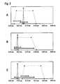
- FIG. 3shows an examination of the pain sensations occurring in the different temporal sequences.
- the experimentswere carried out with 27 subjects and compared with appropriate blood samples in the same subjects with a Softclix®.
- FIG. 3Ishows the number of blood samples, which were perceived by the subjects as pain-free.
- the dashed barscorrespond to the time sequences A, B, C as in FIG. 2 shown.
- the black bars immediately adjacent to the rightshow the number of blood samples taken as painless with a conventional Softclix®. It can be seen from the figure that the number of perceived as painless blood withdrawals could be increased by exerting the pulse.
- variant Cin which the blow occurred about 30 msec after the sting, is favorable in terms of pain perception.
- FIG. 3IIshows a classification of the painfulness of the blood withdrawals with and without blow.
- the dashed barsrepresent averaged pain maps as they do for the corresponding time sequences A, B, C FIG. 2 were obtained.
- the black bars on the rightare in turn comparative measurements with a conventional Softclix®. It can also be seen in this illustration that the use of the pulse on average a significant reduction in the perceived pain could be achieved.
- FIG. 4shows a railway - controlled system with a rotary vane gearbox, which is based on the drive concept of the EP 0 565 970 builds.
- the systemhas a housing (11), which serves for manual handling, and in which the drive mechanism is arranged.
- the driveincludes an elastic drive element, in the present case a spring (50) which is fixed at one end to the housing and at its other end with a gear member, in the special case of a guide sleeve (51) is connected. By turning the guide sleeve (51), the spring (50) can be tensioned, so that they are in relaxing the spring in the in FIG. 4A rotated direction shown.
- the sleeve (51)carries two grooves (52, 53), of which the first (52) serves to drive the lancet holder (40).
- the sequence A, B, Cshows how the lancet holder and thus also the lancet (30) fixed in it are moved when the sleeve (51) rotates.
- the lancet holder (40)has a pin (41) attached to it, which runs in the first groove (52). The lancet holder is secured against rotation, so that it is displaced by rotation of the sleeve from position A to position B by the pin forward and reaches the extreme point (52 ').
- the needle (30 ') of the lancet (30)emerges from the housing through an opening in the contact surface (15) and optionally punctures a body part pressed there.
- the sleeve (51)which is about 45 °, passes through the pin (61) which is connected to a cylindrical mass (60) as the pulse weight in the second groove (53) through a substantially straight portion.
- the massundergoes a sharp change in the speed of movement in magnitude and / or direction by the pin (61) in the stroke position (53 ') passes.
- the housingexperiences an impulse in the direction of the contact surface so that it exerts a shock on a body part located on the contact surface. Due to the operation it can be seen that by the radial position of the extreme points (52 ') and (53'), as well as the rotational speed of the sleeve (51) the time interval between the stitch and the stroke can be adjusted.
- cams grooves (52, 53)By acting as cams grooves (52, 53), the path-time course of both the stitch and the return movement and the time course of the shock / pulse can be specified exactly.
- the mass of the drive mechanism and the housingare relatively small, on the other hand, the mass of the pulse weight on the other hand is as large as possible, so that the internal force that accelerates the two masses relative to each other, to the largest possible acceleration of the device housing leads. If the pulse weight were small in comparison to the mass of housing and drive, this relative acceleration would be low.
- FIG. 5shows a blood collection system with a pulse generator having a drive with two elastic drive elements.
- the housing (111)is a unit of a lancet holder (140) and a fixed to it mass (160), the pulse mass disposed. This unit is tensioned against a drive spring (150) and locked with a lever (170).
- a lancet (130)Within the lancet holder is a lancet (130) with a needle (130 ') for creating a skin opening.
- the lancet holder and mass unit and thus also the lancetare accelerated by the drive spring (150) towards the cap (105) where the contact surface (115) is located.
- This forward accelerationis preferably done over a relatively long distance in order to keep the acceleration in that phase of magnitude small.
- the needle (130 ')exits an opening in the contact surface (115) so that it can create a skin opening in a body part pressed against the contact surface.
- a second springthe return spring (152)
- the forward movement of the lancet holderis brought to a standstill with its mass. This braking process takes place in a relatively short way, resulting in a large amount of acceleration. Subsequently, the lancet holder is withdrawn by the return spring and thus the needle from the wound produced.
- Housing (111) and cap (105)are arranged axially displaceable relative to each other by the cap (105) has an area with an enlarged inner cross-section (105 '), in which the front part of the housing (111) is inserted.
- the reaction force of the decelerationis transferred to the cap, which exerts a blow to a located on the contact surface body part.
- the capcan be rigidly connected to the device housing. But by the mobility of the Cap is the mass of the device housing used to capture the starting acceleration, but does not interfere with the transmission of braking acceleration on the cap by the moving mass and thus on the body.
- the spring-mass drive according to FIG. 5it is advantageous if the housing mass is relatively large.
- the pulse massis accelerated forward with the lancet holder. If this drive acceleration should not cause the device to be lifted off the surface to be staked, then the outwardly noticeable reaction must be sufficiently small. This is achieved by long acceleration paths and thus low acceleration amounts and / or by a large housing mass.
- the braking acceleration of the lancet holder with its pulse massshould be transmitted as undamped as possible to the surface to be staked, which requires a low housing mass relative to the pulse mass.
- the mobility of the capnow decouples a (light) part of the rest of the housing, then the braking acceleration of the pulse mass acts on, so that the two opposite goals (no lifting of body surface, strongest possible impulse on the body surface) can be achieved in one device.
- a mechanismis preferably used which, upon retraction of the lancet holder in the cocked position according to FIG. 5A also the cap in the starting position according to FIG. 5A retracts, so that it again has a possibility of movement in the direction of the contact surface when triggered.
- a means of regulating the depth of penetrationcan be achieved, for example, by a two-part cap (105) having a first part which comprises the region of increased internal cross-section (105 ') and further comprises a thread.
- a second partincludes the pressure surface (115) and also has a thread which fits to the first thread.
- the two partsare now screwed together and by screwing the parts against each other, the puncture depth can be regulated.
- FIG. 5A illustrated starting positionin which the area is widened with widened inner cross-section as far as possible by the housing (111) is defined by a stop or other means defined.
Landscapes
- Health & Medical Sciences (AREA)
- Life Sciences & Earth Sciences (AREA)
- Heart & Thoracic Surgery (AREA)
- Surgery (AREA)
- Physics & Mathematics (AREA)
- Veterinary Medicine (AREA)
- Biophysics (AREA)
- Pathology (AREA)
- Engineering & Computer Science (AREA)
- Biomedical Technology (AREA)
- Public Health (AREA)
- Medical Informatics (AREA)
- Molecular Biology (AREA)
- Hematology (AREA)
- Animal Behavior & Ethology (AREA)
- General Health & Medical Sciences (AREA)
- Dermatology (AREA)
- Pain & Pain Management (AREA)
- Immunology (AREA)
- Vascular Medicine (AREA)
- Measurement Of The Respiration, Hearing Ability, Form, And Blood Characteristics Of Living Organisms (AREA)
- External Artificial Organs (AREA)
- Surgical Instruments (AREA)
Abstract
Description
Translated fromGermanDie vorliegende Erfindung betrifft ein System zur schmerzfreien Blutentnahme, welches ein Lanzettensystem umfaßt, mit dem eine kleine Hautöffnung erzeugt wird, aus der Blut austreten kann, sowie einen Impulsgeber, der dazu dient, das Schmerzempfinden bei der Blutentnahme zu verringern.The present invention relates to a system for painless blood collection, which comprises a lancet system, with which a small skin opening is created, can escape from the blood, and a pulse generator, which serves to reduce the pain sensation during blood collection.
Systeme zur Blutentnahme werden vorwiegend von Diabetikern benutzt, um den Blutzuckerspiegel zu kontrollieren. Derartige Blutentnahmegeräte werden jedoch auch in Arztpraxen, Krankenhäusern usw. eingesetzt, sofern für eine Untersuchung bzw. einen analytischen Test lediglich kleine Blutmengen im Bereich weniger µl oder darunter benötigt werden. Aufgrund der Notwendigkeit einer häufigen Testung haben sich die Blutentnahmegeräte jedoch eine besondere Bedeutung unter Diabetikern erworben. Hier ist eine ständige, häufig täglich mehrfache Blutentnahme notwendig, um zu hohe oder auch zu niedrige Blutzuckerwerte zu vermeiden und so Spätfolgen zu reduzieren. Während eine Kontrolle des Blutzuckerspiegels für Typ 1 Diabetiker nahezu unerläßlich ist und der von einer Vielzahl der Betroffenen auch durchgeführt wird, gehen eine Vielzahl von Typ 2 Diabetikern, der sogenannten Altersdiabetes, wesentlich unachtsamer mit ihrer Erkrankung um und führen keine oder nur unregelmäßige Blutzuckermessungen durch. Ein wesentlicher Grund für dieses Verhalten liegt in der für eine Analyse notwendigen Blutentnahme, die als schmerzhaft oder zumindest als unangenehm empfunden wird. Es ist daher ein wichtiges Ziel, den für eine Blutentnahme auftretenden Schmerz weitestgehend zu reduzieren, um Diabetikern das Leben zu erleichtern als auch um eine größere Zahl von Typ 2 Diabetikern zur Blutzuckermessung zu bewegen. So kann sowohl ein persönlicher als auch ein gesamtwirtschaftlicher Nutzen durch Vermeidung von Folgeerkrankungen erzielt werden.Blood collection systems are used primarily by diabetics to control blood sugar levels. However, such blood collection devices are also used in medical practices, hospitals, etc., provided that only small amounts of blood in the range of less than or equal to less than one are required for an examination or an analytical test. However, because of the need for frequent testing, the blood collection devices have acquired particular importance among diabetics. Here, a constant, often daily multiple blood sampling is necessary to avoid too high or too low blood sugar levels and so to reduce long-term consequences. While a control of the blood sugar level for type 1 diabetics is almost indispensable and is carried out by a large number of those affected, a variety of type 2 diabetics, the so-called old-age diabetes, are much more careless with their disease and perform no or only irregular blood glucose measurements. One of the main reasons for this behavior is the need for an analysis blood collection, which is perceived as painful or at least unpleasant. It is therefore an important goal to greatly reduce the pain associated with a blood sample, to make life easier for diabetics, as well as to drive a larger number of type 2 diabetics for blood glucose monitoring. Thus, both a personal and a macroeconomic benefit can be achieved by avoiding secondary diseases.
Im Stand der Technik hat es bereits einige Bestrebungen gegeben, den beim Einstich auftretenden Schmerz zu verringern. Einen nicht unerheblichen Einfluß auf den ausgelösten Schmerz hat die Form der verwendeten Lanzettennadel, so daß durch eine Optimierung des Schliffes der Lanzettennadel bereits eine gewisse Schmerzreduktion erzielt werden kann. Weiterhin hat die Art der Stichbewegung einen Einfluß auf die Höhe des Schmerzes. Bei herkömmlichen Systemen, bei denen die Lanzette durch eine Feder auf einen Anschlag beschleunigt wird, tritt während des Stiches eine Vibration der Nadel auf, die Schmerz erzeugt. In dem
In der
In der
Die Aufgabe der vorliegenden Erfindung bestand darin, eine Lanzettenvorrichtung zu Blutentnahme vorzuschlagen, welche den Schmerz bei der Entnahme minimiert und die eine hygienische Benutzung ermöglicht.The object of the present invention was to propose a lancet device for blood collection, which minimizes the pain during removal and allows a hygienic use.
Gemäß der angegebenen Aufgabenstellung wird ein Lanzettensystem zur schmerzarmen Blutentnahme vorgeschlagen, welches ein Gehäuse mit einer Kontaktfläche aufweist, aus der die Spitze einer Lanzette austreten kann, wobei die in einem Lanzettenhalter befindliche Lanzette mittels eines Lanzettenantriebes verfahren wird und ein Impulsgeber zeitlich abgestimmt auf den Einstich der Lanzette einen Impuls auf ein Körperteil ausübt, so daß das durch den Einstich verursachte Schmerzempfinden verringert wird.According to the specified task, a lancet system for low-pain blood sampling is proposed, which has a housing with a contact surface from which the tip of a lancet can emerge, wherein the lancet located in a lancet holder is moved by means of a lancet drive and a pulse generator timed to the puncture of Lancet impulse on a body part, so that the pain caused by the puncture is reduced.
Ein Verfahren zur schmerzarmen Blutentnahme wird weiterhin beschrieben, bei dem in zeitlich abgestimmter Folge zum Einstich in eine Körperoberfläche ein Impuls auf ein Körperteil ausgeübt wird.A method for low-pain blood sampling is further described, in which in timed sequence for puncture in a body surface, an impulse is exerted on a body part.
Durch das erfindungsgemäße System werden wesentliche Verbesserungen in dem Ziel erreicht, das Schmerzempfinden bei dem Stich mit einer Lanzette zu verringern. Durch die Bewegung des Lanzettenhalters und somit auch der Lanzette entlang eines vorbestimmten Einstichweges kann die Einstechtiefe kontrolliert und ggf. auch reguliert werden. Weiterhin wird durch eine zeitliche Abstimmung des auf die Haut ausgeübten Impulses relativ zum Zeitpunkt des Einstiches in den Körper eine Optimierung des Effekts der Schmerzmaskierung erzielt.The system according to the invention achieves substantial improvements in the goal of lessening pain in the lancet. By the movement of the lancet holder and thus also the lancet along a predetermined puncture path, the puncture depth can be controlled and optionally also regulated. Furthermore, timing of the pulse applied to the skin relative to the time of puncture into the body optimizes the effect of pain masking.
Das Lanzettensystem besitzt ein Gehäuse mit einer Kontaktfläche, die ein Benutzer des Systems auf einer Körperstelle positionieren kann, aus der eine Blutentnahme erfolgen soll. Das Gehäuse dient dabei sowohl zur Handhabung durch den Benutzer als auch zum Schutz der Mechanik und der Lanzette gegenüber der Umgebung. Die Kontaktfläche, welche an den Körper angedrückt wird, weist eine Öffnung auf, durch die die Spitze einer Lanzette aus dem Innenraum des Gehäuses austreten kann, um in Haut einzustechen. Die Austrittsöffnung in der Kontaktfläche weist vorzugsweise einen Querschnitt unter 5 mm, günstigenfalls zwischen 1 und 3 mm auf. Die Kontaktfläche, welche für eine Blutentnahme an den Körper angedrückt wird, kann beispielsweise die Form eines planen Kreisringes aufweisen. Es hat sich jedoch aus vorteilhaft erwiesen, für eine Blutentnahme aus der Fingerbeere auf der Kontaktfläche in direkter Nachbarschaft zu der Austrittsöffnung einen kleinen Wulst vorzusehen, der beispielsweise die Form eines um die Austrittsöffnung umlaufenden Ringes aufweist, um die Haut im Einstichbereich vorzuspannen. Weiterhin können an der Kontaktfläche auch Vorsprünge vorgesehen werden, die über die Ebene der Kontaktfläche hinausragen, und so beim Andrücken an den Körper eine Stimulierung der Nerven verursachen. Eine geeignete Anordnung ist in
Im Bereich der Blutentnahmesysteme hat es sich eingebürgert, austauschbare Lanzetten zu verwenden, die der Benutzer aus hygienischen Gründen nach einmaliger oder unter Umständen mehrfacher Benutzung austauschen kann. Insbesondere, wenn ein Blutentnahmesystem von mehreren Benutzern verwendet wird, ist eine leichte Austauschbarkeit der Lanzetten wichtig. Bei herkömmlichen Systemen erfolgt der Austausch beispielsweise durch Abnehmen einer Kappe am vorderen Ende des Gehäuses und Auswerfen der Lanzette aus einer Halterung. Es ist jedoch auch möglich, daß das System ein Magazin für Lanzetten aufweist, in das eine gebrauchte Lanzette zurückgezogen und / oder durch das eine neue Lanzette in den Lanzettenhalter eingebracht wird.In the field of blood collection systems, it has become commonplace to use interchangeable lancets, which the user can exchange for hygienic reasons after one or more times multiple use. In particular, when a blood collection system is used by multiple users, easy interchangeability of the lancets is important. In conventional systems, for example, the replacement takes place by removing a cap at the front end of the housing and ejecting the lancet from a holder. However, it is also possible that the system has a lancet magazine into which a used lancet is withdrawn and / or inserted into the lancet holder by a new lancet.
Unter einer Lanzette soll im Rahmen dieser Erfindung eine Vorrichtung verstanden werden, die eine Nadel mit einer Spitze aufweist, welche geeignet ist, eine Körperöffnung zu erzeugen. Eine solche Nadel kann dabei sowohl eine Vollnadel sein als auch eine Hohlnadel. Geeignete Materialien für die Nadel sind insbesondere Metalle, wie vor allem Edelstähle aber auch Klingen aus Flachstahl, Silizium, Keramik etc. Es ist möglich, eine solche Nadel ohne weiteres in einer Halterung des Blutentnahmesystems zu haltern. Vorteilhaft weist die Lanzette jedoch neben der Nadel einen Haltekörper auf, in dem sich die Nadel befindet. Solche Haltekörper können aus Kunststoff gefertigt sein, welcher in einem Spritzgußverfahren um die Nadel gespritzt wird. Durch diesen Haltekörper ist es einfach möglich, die Lanzette in einer Halterung des Systems zu haltern. Weiterhin kann der Haltekörper auch so ausgestaltet sein, daß er den Spitzenbereich der Nadel mit umschließt und ihn so vor Benutzung vor einer Kontamination schützt. Eine derartige Versiegelung kann durch Abdrehen an einer Sollbruchstelle entfernt werden, so daß die Nadelspitze für eine Blutentnahme frei liegt. Da Konzepte zur Halterung einer Nadel in einem Körper und auch die hygienische Versiegelung der Nadelspitze im Stand der Technik hinlänglich bekannt sind, wird an dieser Stelle nicht näher darauf eingegangen.In the context of this invention, a lancet is to be understood as meaning a device which has a needle with a tip which is suitable for generating a body opening. Such a needle can be both a solid needle and a hollow needle. Suitable materials for the needle are in particular metals, especially stainless steels but also blades made of flat steel, silicon, ceramic, etc. It is possible to hold such a needle readily in a holder of the blood collection system. However, the lancet advantageously has, in addition to the needle, a holding body in which the needle is located. Such holding bodies may be made of plastic, which is injection-molded around the needle. By this holding body, it is easily possible to hold the lancet in a holder of the system. Furthermore, the holding body can also be designed so that it encloses the tip region of the needle and thus protects it from contamination before use. Such a seal can be removed by twisting off at a predetermined breaking point, so that the needle tip is exposed for a blood sample. Since concepts for holding a needle in a body and also the hygienic sealing of the needle tip in the prior art are well known, it will not be discussed in more detail here.
Zur Halterung der Lanzette besitzt das Blutentnahmesystem einen beweglichen Lanzettenhalter, der entlang eines vorbestimmten Weges verfahren werden kann, um einen Stich für eine Blutentnahme durchzuführen. Die Lanzette kann in dem Lanzettenhalter beispielsweise durch Preßsitz oder durch Verklemmen oder Verrasten gehaltert sein. Ein im Rahmen der vorliegenden Erfindung besonders geeigneter Lanzettenhalter ist in der
Der Lanzettenhalter wird durch einen Lanzettenantrieb entlang eines vorbestimmten Weges bewegt, so daß eine Lanzette, die in dem Lanzettenhalter angeordnet ist, zeitweise durch die Austrittsöffnung austritt und in eine dort angeordnete Körperpartie einstechen kann. Im Stand der Technik sind eine Vielzahl von Lanzettenantrieben bekannt. Zum einen gibt es Antriebe, bei denen eine Antriebsfeder den Lanzettenhalter mit der Lanzette auf einen Anschlag fährt, wobei der Einstich in den Körper im Endbereich dieser Bewegung liegt. Die Feder kann so beschaffen sein, daß sie die Lanzette aus der Einstichposition wieder zurückzieht und eine Ruheposition einnimmt, bei der sich die Nadel innerhalb des Gehäuses befindet. Zum Zurückfahren der Nadel in das Gehäuse kann jedoch auch eine zweite Feder vorgesehen werden, die die Lanzette aus der Einstichposition in das Gehäuse zurücktreibt. Weiterhin kommen als Antrieb zwangs führende Systeme in Frage wie z. B. Kurbeltriebe, Hebelgetriebe oder Nockensteuerungen, bei denen die Bewegung der Lanzette nicht dem freien Spiel von Feder- und Massenkräften überlassen wird, sondern durch die Antriebsmechanik genau vorgegeben ist. Als besonders vorteilhaft hat sich im Rahmen der vorliegenden Erfindung ein Antrieb gemäß der
Ein spezielles Merkmal des erfindungsgemäßen Blutentnahmesystems ist ein Impulsgeber, mit dem in zeitlich abgestimmter Abfolge zum Stechen mit der Lanzette ein Impuls auf ein Körperteil ausgeübt wird. Durch einen solchen Impuls werden Mechanorezeptoren im Gewebe gereizt. Diese Rezeptoren sind mit dicken Nervenfasern verbunden, die eine hohe Leitungsgeschwindigkeit haben. Schmerzrezeptoren (Nozizeptoren), welche durch den Einstich aktiviert werden, sind hingegen mit dünneren und langsamer leitenden Nervenfasern verbunden. Das Rückenmark stellt ein Gate dar, bei dem die Fasern aus der Peripherie ankommen und verschaltet werden. Die dünnen Nervenfasern von den Nozizeptoren öffnen das Gate, so daß Schmerzempfindungen zum Gehirn gelangen können. Die dicken Nervenfasern der Mechanorezeptoren hingegen schließen das Gate. Die Bilanz aus ankommenden Signalen von dünnen und dicken Fasern bestimmt das Schmerzempfinden. Diese Effekte sind auch unter der Bezeichnung Gate-Control-Theorie bekannt.A special feature of the blood collection system according to the invention is a pulse generator with which a pulse is exerted on a body part in a chronologically coordinated sequence for piercing with the lancet. Such an impulse stimulates mechanoreceptors in the tissue. These receptors are associated with thick nerve fibers that have a high conduction velocity. Pain receptors (nociceptors), which are activated by the puncture, however, are associated with thinner and slower conducting nerve fibers. The spinal cord is a gate in which the fibers arrive from the periphery and are interconnected. The thin nerve fibers from the nociceptors open the gate so that pain sensations can reach the brain. By contrast, the thick nerve fibers of the mechanoreceptors close the gate. The balance of incoming signals from thin and thick fibers determines the sensation of pain. These effects are also known as gate control theory.
Durch einen mechanischen Impuls, der in zeitlich abgestimmter Folge zum Stich der Lanzette ausgeübt wird, kann durch Anregung der Mechanorezeptoren das Schmerzempfinden aufgrund eines Einstiches der Nadel reduziert oder ganz unterdrückt werden. Da die Signale der Mechanorezeptoren über die dicken Nervenfasern schneller geleitet werden als die Signale der Nozizeptoren, können sie, selbst wenn sie nach den Nozizeptoren gereizt werden, deren Signale überholen und so das Gate schließen, bevor das Schmerzsignal dort eintrifft. Erfindungsgemäß kann daher der Impuls auf das Körperteil sowohl vor dem Stich als auch noch kurz danach ausgeübt werden. Unsere Untersuchungen haben gezeigt, daß der Impuls, wenn er zwischen 1000 und 0 Millisekunden vor dem Stich oder zwischen 0 und 100 Millisekunden noch besser, zwischen 20 und 50 Millisekunden nach dem Stich ausgeübt wird zu einer Reduktion des empfundenen Schmerzes führt.By stimulating the mechanoreceptors, the sensation of pain due to a puncture of the needle can be reduced or completely suppressed by stimulating the mechanoreceptors by means of a mechanical impulse which is applied to the puncture of the lancet in a timed sequence. Because the mechanoreceptor signals are conducted faster through the thick nerve fibers than the nociceptor signals, even if stimulated by the nociceptors, they can overtake their signals, closing the gate before the pain signal arrives there. According to the invention, therefore, the impulse can be exerted on the body part both before the sting and shortly thereafter. Our investigations have shown that the pulse, when applied between 1000 and 0 milliseconds before the sting or between 0 and 100 milliseconds even better, between 20 and 50 milliseconds after the sting, leads to a reduction of the perceived pain.
Der Impuls auf den Körperteil wird von dem Impulsgeber durch die Kontaktfläche des Gehäuses ausgeübt. Impulsgeber und Lanzettenantrieb können beispielsweise separat voneinander aufgebaut sein und von einer Steuervorrichtung elektrisch angesteuert werden. Es hat sich jedoch als vorteilhaft erwiesen, Impulsgeber und Lanzettenantrieb mechanisch miteinander zu koppeln, so daß der Impuls und der Stich durch diese mechanische Kopplung aufeinander abgestimmt sind. Spezielle Ausführungsformen mechanischer Kopplung werden im Zusammenhang mit den Figuren detaillierter beschrieben.The impulse on the body part is exerted by the pulse generator through the contact surface of the housing. Pulse generator and lancet drive, for example, be constructed separately from each other and electrically controlled by a control device. However, it has proven to be advantageous to couple the pulse generator and lancet drive mechanically together, so that the pulse and the stitch are coordinated by this mechanical coupling. Specific embodiments of mechanical coupling will be described in more detail in conjunction with the figures.
Bei Blutentnahmesystemen handelt es sich im Regelfall um relativ kleine Vorrichtungen, beispielsweise in Form eines Stiftes, die manuell gehaltert werden. Bei einer solchen Vorrichtung wird der Impuls durch eine Relativbewegung von begrenzt großen Massen. Das Verhältnis der Massen zueinander und ihre Relativgeschwindigkeit bestimmt und damit die auf das Körperteil ausgeübte Kraft zur Reizung der Rezeptoren. Es hat sich als vorteilhaft erwiesen, im Inneren des Gehäuses eine Masse zur Erzeugung des Impulses vorzusehen, die relativ zum Gehäuse bewegt wird. Wird diese Masse durch einen Antrieb von der Kontaktfläche wegbeschleunigt, so übt das Gehäuse mit der Kontaktfläche einen Impuls auf das Körperteil aus. Im Falle einer Irnpulsübertragung auf dem Körper mit Hilfe eines Stößels findet ebenfalls eine Relativbewegung von Massen statt, wobei sich nunmehr das Gehäuse vom Körperteil wegbewegt.Blood collection systems are usually relatively small devices, such as a pen, which are manually held. In such a device, the pulse is due to a relative movement of limited masses. The ratio of the masses to each other and their relative velocity determines and thus the force exerted on the body part force to irritate the receptors. It has proven to be advantageous to provide inside the housing a mass for generating the pulse, which is moved relative to the housing. If this mass is accelerated away from the contact surface by a drive, the housing with the contact surface exerts an impulse on the body part. In the case of an impulse transmission on the body with the aid of a plunger, a relative movement of masses also takes place, whereby now the housing moves away from the body part.
Erfindungsgemäß wurde gefunden, daß der Impuls vorzugsweise eine Dauer im Bereich von 0 bis 10 oder noch besser im Bereich zwischen 1 und 7 msec aufweisen sollte, um eine effiziente Schmerzmaskierung zu erzielen. Dies bedeutet, daß der Impuls nicht andauert sondern - vorzugsweise durch das Blutentnahmesystem selbst - nach kurzer Zeit wieder rückgängig gemacht wird, indem die auseinander bewegten Massen wieder zusammengezogen werden.According to the invention, it has been found that the pulse should preferably have a duration in the range of 0 to 10 or even better in the range between 1 and 7 msec in order to achieve an efficient pain masking. This means that the pulse does not last but is reversed after a short time, preferably by the blood sampling system itself, by contracting the separated masses again.
Die Kraft, die durch den Impulsgeber auf das Körperteil ausgeübt wird, liegt vorzugsweise im Bereich von 10 bis 30 N.The force exerted by the pulse generator on the body part is preferably in the range of 10 to 30 N.
Die Erfindung wird nunmehr an einigen Beispielen näher erläutert:
Figur 1 : Blutentnahmesystem mit einem Stößel als ImpulsgeberFigur 2 : Weg-Zeit-Verläufe von Stich und Impuls mit dem inFigur 1 dargestellten SystemFigur 3 : Bewertung des Schmerzempfindens bei den inFigur 2 dargestellten Weg-Zeit-Verläufen durch ProbandenFigur 4 : Blutentnahmesystem mit einem DrehschiebergetriebeFigur 5 : Blutentnahmesystem mit einer federgetriebenen Masse
FIG. 1 : Blood collection system with a plunger as a pulse generatorFIG. 2 : Path-time-courses of stitch and impulse with the inFIG. 1 illustrated systemFIG. 3 : Assessment of the pain sensation in theFIG. 2 illustrated path-time courses by subjectsFIG. 4 : Blood collection system with a rotary transmissionFIG. 5 : Blood collection system with a spring-driven mass
In
Bei diesem System ist es vorteilhaft, wenn einerseits die Masse des Antriebsmechanismus und des Gehäuses relativ klein sind, die Masse des Impulsgewichtes andererseits dagegen möglichst groß ist, damit die innere Kraft, die die beiden Massen relativ zueinander beschleunigt, zu einer möglichst großen Beschleunigung des Gerätegehäuses führt. Wäre das Impulsgewicht klein im Vergleich zu der Masse von Gehäuse und Antrieb so wäre diese Relativbeschleunigung gering.In this system, it is advantageous if on the one hand, the mass of the drive mechanism and the housing are relatively small, on the other hand, the mass of the pulse weight on the other hand is as large as possible, so that the internal force that accelerates the two masses relative to each other, to the largest possible acceleration of the device housing leads. If the pulse weight were small in comparison to the mass of housing and drive, this relative acceleration would be low.
Wie beim bahngesteuerten Antrieb gemäß
Zum Spannen der Anordnung wird vorzugsweise ein Mechanismus verwendet, der beim Zurückziehen des Lanzettenhalters in die gespannte Position gemäß
In das System gemäß
Claims (11)
- Lancet system (10) for pain-reduced blood withdrawal comprising,• a housing (11, 111) with a contact surface (15, 115) which has an exit opening for the tip of a lancet,• a lancet holder (40, 140) for holding the lancet which can move in the housing (11) along a lancing path,• a lancet drive for moving the lancet holder (40, 140) along the lancing path,• an impulse generator (60) which can exert an impulse on a body part in a sequence that is synchronized with the movement of the lancet holder (40, 140) so that pain sensation is reduced or suppressed as a result of the exerted impulse,characterized in that the impulse is transferred by the contact surface (15, 115) onto the body.
- System according to claim 1 which is designed such that the impulse can be exerted between 0 and 100 ms and preferably between 20 and 50 ms after the tip of the lancet has emerged from the exit opening.
- System according to claim 1 which is designed such that the impulse can be exerted between 1000 and 0 ms before the tip of the lancet has emerged from the exit opening.
- System according to claim 1 which has a device for adjusting the length of the lancet tip which protrudes beyond the contact surface (15, 115).
- System according to claim 1 in which the impulse generator (60, 160) and the lancet drive are mechanically coupled together.
- System according to claim 1 in which the impulse generator (60, 160) comprises a rotary slide gear with a gear member which has an axis of rotation which is parallel to the lancing path and which can be driven by an elastic drive element, and the system additionally comprises a mass whose movement is controlled by the gear member.
- System according to claim 6 in which the movement of the lancet holder (40, 140) can be controlled by the gear member.
- System according to claim 1 which has a cap that can be moved relative to the housing (11, 111), the contact surface with the exit opening being located on said cap.
- System according to claim 8 which has a first elastic drive element for moving the lancet holder (40, 140) into a lancing position and a second elastic drive element for retracting the lancet tip into the housing (11, 111), wherein the second elastic drive element is mounted against the movable cap.
- System according to claim 1 in which the impulse generator (60, 160) can exert a maximum force in the range of 10 to 30 N on the body part.
- System according to claim 1 in which the contact surface (15, 115) has a profiled surface with which the impulse is applied.
Applications Claiming Priority (2)
| Application Number | Priority Date | Filing Date | Title |
|---|---|---|---|
| DE10206254ADE10206254A1 (en) | 2002-02-15 | 2002-02-15 | System for taking pain-free blood |
| DE10206254 | 2002-02-15 |
Publications (3)
| Publication Number | Publication Date |
|---|---|
| EP1336375A2 EP1336375A2 (en) | 2003-08-20 |
| EP1336375A3 EP1336375A3 (en) | 2004-01-14 |
| EP1336375B1true EP1336375B1 (en) | 2010-05-05 |
Family
ID=27618704
Family Applications (1)
| Application Number | Title | Priority Date | Filing Date |
|---|---|---|---|
| EP03003032AExpired - LifetimeEP1336375B1 (en) | 2002-02-15 | 2003-02-12 | System for painless blood sampling |
Country Status (6)
| Country | Link |
|---|---|
| US (1) | US7244266B2 (en) |
| EP (1) | EP1336375B1 (en) |
| JP (1) | JP3643363B2 (en) |
| AT (1) | ATE466525T1 (en) |
| CA (1) | CA2418665C (en) |
| DE (2) | DE10206254A1 (en) |
Families Citing this family (89)
| Publication number | Priority date | Publication date | Assignee | Title |
|---|---|---|---|---|
| US6036924A (en) | 1997-12-04 | 2000-03-14 | Hewlett-Packard Company | Cassette of lancet cartridges for sampling blood |
| US6391005B1 (en) | 1998-03-30 | 2002-05-21 | Agilent Technologies, Inc. | Apparatus and method for penetration with shaft having a sensor for sensing penetration depth |
| US8641644B2 (en) | 2000-11-21 | 2014-02-04 | Sanofi-Aventis Deutschland Gmbh | Blood testing apparatus having a rotatable cartridge with multiple lancing elements and testing means |
| US7041068B2 (en) | 2001-06-12 | 2006-05-09 | Pelikan Technologies, Inc. | Sampling module device and method |
| US7344507B2 (en) | 2002-04-19 | 2008-03-18 | Pelikan Technologies, Inc. | Method and apparatus for lancet actuation |
| JP4272051B2 (en) | 2001-06-12 | 2009-06-03 | ペリカン テクノロジーズ インコーポレイテッド | Blood sampling apparatus and method |
| US8337419B2 (en) | 2002-04-19 | 2012-12-25 | Sanofi-Aventis Deutschland Gmbh | Tissue penetration device |
| WO2002101359A2 (en) | 2001-06-12 | 2002-12-19 | Pelikan Technologies, Inc. | Integrated blood sampling analysis system with multi-use sampling module |
| US9226699B2 (en) | 2002-04-19 | 2016-01-05 | Sanofi-Aventis Deutschland Gmbh | Body fluid sampling module with a continuous compression tissue interface surface |
| US9795747B2 (en) | 2010-06-02 | 2017-10-24 | Sanofi-Aventis Deutschland Gmbh | Methods and apparatus for lancet actuation |
| US9427532B2 (en) | 2001-06-12 | 2016-08-30 | Sanofi-Aventis Deutschland Gmbh | Tissue penetration device |
| US7749174B2 (en) | 2001-06-12 | 2010-07-06 | Pelikan Technologies, Inc. | Method and apparatus for lancet launching device intergrated onto a blood-sampling cartridge |
| US7981056B2 (en) | 2002-04-19 | 2011-07-19 | Pelikan Technologies, Inc. | Methods and apparatus for lancet actuation |
| EP1395185B1 (en) | 2001-06-12 | 2010-10-27 | Pelikan Technologies Inc. | Electric lancet actuator |
| JP4209767B2 (en) | 2001-06-12 | 2009-01-14 | ペリカン テクノロジーズ インコーポレイテッド | Self-optimized cutting instrument with adaptive means for temporary changes in skin properties |
| AU2002344825A1 (en) | 2001-06-12 | 2002-12-23 | Pelikan Technologies, Inc. | Method and apparatus for improving success rate of blood yield from a fingerstick |
| US7344894B2 (en) | 2001-10-16 | 2008-03-18 | Agilent Technologies, Inc. | Thermal regulation of fluidic samples within a diagnostic cartridge |
| US20040098010A1 (en)* | 2001-10-22 | 2004-05-20 | Glenn Davison | Confuser crown skin pricker |
| US8702624B2 (en) | 2006-09-29 | 2014-04-22 | Sanofi-Aventis Deutschland Gmbh | Analyte measurement device with a single shot actuator |
| US7901362B2 (en) | 2002-04-19 | 2011-03-08 | Pelikan Technologies, Inc. | Method and apparatus for penetrating tissue |
| WO2003088824A2 (en) | 2002-04-19 | 2003-10-30 | Pelikan Technologies, Inc. | Device and method for variable speed lancet |
| US9795334B2 (en) | 2002-04-19 | 2017-10-24 | Sanofi-Aventis Deutschland Gmbh | Method and apparatus for penetrating tissue |
| US8267870B2 (en) | 2002-04-19 | 2012-09-18 | Sanofi-Aventis Deutschland Gmbh | Method and apparatus for body fluid sampling with hybrid actuation |
| US7648468B2 (en) | 2002-04-19 | 2010-01-19 | Pelikon Technologies, Inc. | Method and apparatus for penetrating tissue |
| US7485128B2 (en) | 2002-04-19 | 2009-02-03 | Pelikan Technologies, Inc. | Method and apparatus for penetrating tissue |
| US7229458B2 (en) | 2002-04-19 | 2007-06-12 | Pelikan Technologies, Inc. | Method and apparatus for penetrating tissue |
| US8360992B2 (en) | 2002-04-19 | 2013-01-29 | Sanofi-Aventis Deutschland Gmbh | Method and apparatus for penetrating tissue |
| US7524293B2 (en) | 2002-04-19 | 2009-04-28 | Pelikan Technologies, Inc. | Method and apparatus for penetrating tissue |
| US7563232B2 (en) | 2002-04-19 | 2009-07-21 | Pelikan Technologies, Inc. | Method and apparatus for penetrating tissue |
| US8221334B2 (en) | 2002-04-19 | 2012-07-17 | Sanofi-Aventis Deutschland Gmbh | Method and apparatus for penetrating tissue |
| US7717863B2 (en) | 2002-04-19 | 2010-05-18 | Pelikan Technologies, Inc. | Method and apparatus for penetrating tissue |
| US9248267B2 (en) | 2002-04-19 | 2016-02-02 | Sanofi-Aventis Deustchland Gmbh | Tissue penetration device |
| US7674232B2 (en) | 2002-04-19 | 2010-03-09 | Pelikan Technologies, Inc. | Method and apparatus for penetrating tissue |
| US7331931B2 (en) | 2002-04-19 | 2008-02-19 | Pelikan Technologies, Inc. | Method and apparatus for penetrating tissue |
| US7141058B2 (en) | 2002-04-19 | 2006-11-28 | Pelikan Technologies, Inc. | Method and apparatus for a body fluid sampling device using illumination |
| US7892183B2 (en) | 2002-04-19 | 2011-02-22 | Pelikan Technologies, Inc. | Method and apparatus for body fluid sampling and analyte sensing |
| US7244265B2 (en) | 2002-04-19 | 2007-07-17 | Pelikan Technologies, Inc. | Method and apparatus for penetrating tissue |
| US7297122B2 (en) | 2002-04-19 | 2007-11-20 | Pelikan Technologies, Inc. | Method and apparatus for penetrating tissue |
| US7547287B2 (en) | 2002-04-19 | 2009-06-16 | Pelikan Technologies, Inc. | Method and apparatus for penetrating tissue |
| US7410468B2 (en) | 2002-04-19 | 2008-08-12 | Pelikan Technologies, Inc. | Method and apparatus for penetrating tissue |
| US8372016B2 (en) | 2002-04-19 | 2013-02-12 | Sanofi-Aventis Deutschland Gmbh | Method and apparatus for body fluid sampling and analyte sensing |
| US9314194B2 (en) | 2002-04-19 | 2016-04-19 | Sanofi-Aventis Deutschland Gmbh | Tissue penetration device |
| US7708701B2 (en) | 2002-04-19 | 2010-05-04 | Pelikan Technologies, Inc. | Method and apparatus for a multi-use body fluid sampling device |
| US7909778B2 (en) | 2002-04-19 | 2011-03-22 | Pelikan Technologies, Inc. | Method and apparatus for penetrating tissue |
| US7371247B2 (en) | 2002-04-19 | 2008-05-13 | Pelikan Technologies, Inc | Method and apparatus for penetrating tissue |
| US7291117B2 (en) | 2002-04-19 | 2007-11-06 | Pelikan Technologies, Inc. | Method and apparatus for penetrating tissue |
| US8579831B2 (en) | 2002-04-19 | 2013-11-12 | Sanofi-Aventis Deutschland Gmbh | Method and apparatus for penetrating tissue |
| US8784335B2 (en) | 2002-04-19 | 2014-07-22 | Sanofi-Aventis Deutschland Gmbh | Body fluid sampling device with a capacitive sensor |
| US7976476B2 (en) | 2002-04-19 | 2011-07-12 | Pelikan Technologies, Inc. | Device and method for variable speed lancet |
| US7374544B2 (en) | 2002-04-19 | 2008-05-20 | Pelikan Technologies, Inc. | Method and apparatus for penetrating tissue |
| US7491178B2 (en) | 2002-04-19 | 2009-02-17 | Pelikan Technologies, Inc. | Method and apparatus for penetrating tissue |
| US7232451B2 (en) | 2002-04-19 | 2007-06-19 | Pelikan Technologies, Inc. | Method and apparatus for penetrating tissue |
| US8574895B2 (en) | 2002-12-30 | 2013-11-05 | Sanofi-Aventis Deutschland Gmbh | Method and apparatus using optical techniques to measure analyte levels |
| EP1614382B1 (en)* | 2003-04-11 | 2012-07-11 | ARKRAY, Inc. | Needle insertion device |
| EP1614383B1 (en)* | 2003-04-16 | 2017-03-15 | ARKRAY, Inc. | Puncture device |
| JP4296035B2 (en)* | 2003-05-21 | 2009-07-15 | アークレイ株式会社 | Puncture device |
| DE602004028463D1 (en) | 2003-05-30 | 2010-09-16 | Pelikan Technologies Inc | METHOD AND DEVICE FOR INJECTING LIQUID |
| US7850621B2 (en) | 2003-06-06 | 2010-12-14 | Pelikan Technologies, Inc. | Method and apparatus for body fluid sampling and analyte sensing |
| WO2006001797A1 (en) | 2004-06-14 | 2006-01-05 | Pelikan Technologies, Inc. | Low pain penetrating |
| EP1635700B1 (en) | 2003-06-13 | 2016-03-09 | Sanofi-Aventis Deutschland GmbH | Apparatus for a point of care device |
| US8282576B2 (en) | 2003-09-29 | 2012-10-09 | Sanofi-Aventis Deutschland Gmbh | Method and apparatus for an improved sample capture device |
| EP1680014A4 (en) | 2003-10-14 | 2009-01-21 | Pelikan Technologies Inc | METHOD AND DEVICE FOR A VARIABLE USER INTERFACE |
| US8668656B2 (en) | 2003-12-31 | 2014-03-11 | Sanofi-Aventis Deutschland Gmbh | Method and apparatus for improving fluidic flow and sample capture |
| US7822454B1 (en) | 2005-01-03 | 2010-10-26 | Pelikan Technologies, Inc. | Fluid sampling device with improved analyte detecting member configuration |
| WO2006011062A2 (en) | 2004-05-20 | 2006-02-02 | Albatros Technologies Gmbh & Co. Kg | Printable hydrogel for biosensors |
| WO2005120365A1 (en) | 2004-06-03 | 2005-12-22 | Pelikan Technologies, Inc. | Method and apparatus for a fluid sampling device |
| US9775553B2 (en) | 2004-06-03 | 2017-10-03 | Sanofi-Aventis Deutschland Gmbh | Method and apparatus for a fluid sampling device |
| US20080119884A1 (en)* | 2004-09-09 | 2008-05-22 | Flora Bruce A | Single Puncture Lancing Fixture with Depth Adjustment and Control of Contact Force |
| EP1791510B1 (en) | 2004-09-20 | 2015-03-18 | Bing Innovations, LLC | Apparatus and method for reducing pain during skin puncturing procedures |
| US9168340B2 (en) | 2009-03-27 | 2015-10-27 | Bing Innovations, Llc | System and method for pain reduction during skin puncture and breakable tip therefor |
| US9463287B1 (en) | 2004-09-20 | 2016-10-11 | Bing Innovations, Llc | Controlling usage of replaceable tool ends |
| US8622952B2 (en) | 2009-03-27 | 2014-01-07 | Bing Innovations, Llc | System and method for pain reduction during skin puncture and breakable tip therefor |
| WO2010110823A1 (en) | 2009-03-27 | 2010-09-30 | Bing Innovations, Llc | Apparatus and method for reducing pain during skin puncturing procedures |
| US8652831B2 (en) | 2004-12-30 | 2014-02-18 | Sanofi-Aventis Deutschland Gmbh | Method and apparatus for analyte measurement test time |
| US7704265B2 (en)* | 2005-11-03 | 2010-04-27 | Stat Medical Devices, Inc. | Disposable/single-use blade lancet device and method |
| GB0524604D0 (en)* | 2005-12-02 | 2006-01-11 | Owen Mumford Ltd | Injection method and apparatus |
| GB2434103B (en)* | 2006-01-12 | 2009-11-25 | Owen Mumford Ltd | Lancet firing device |
| US20070173876A1 (en)* | 2006-01-20 | 2007-07-26 | Lifescan, Inc. | Lancing device with dampened spring |
| US8328738B2 (en)* | 2007-06-29 | 2012-12-11 | Actuated Medical, Inc. | Medical tool for reduced penetration force with feedback means |
| EP2265324B1 (en) | 2008-04-11 | 2015-01-28 | Sanofi-Aventis Deutschland GmbH | Integrated analyte measurement system |
| US9375169B2 (en) | 2009-01-30 | 2016-06-28 | Sanofi-Aventis Deutschland Gmbh | Cam drive for managing disposable penetrating member actions with a single motor and motor and control system |
| US8965476B2 (en) | 2010-04-16 | 2015-02-24 | Sanofi-Aventis Deutschland Gmbh | Tissue penetration device |
| WO2011131951A1 (en)* | 2010-04-23 | 2011-10-27 | Oliver Blackwell | Apparatus for effecting a vascular puncture in a patient |
| US8469918B2 (en) | 2010-05-24 | 2013-06-25 | Steve FALLEK | Method and apparatus for performing injections while vibrating the skin |
| US9125975B2 (en) | 2010-08-16 | 2015-09-08 | Becton, Dickinson And Company | User-actuated storage assembly for injection device |
| GB2498772A (en)* | 2012-01-27 | 2013-07-31 | Owen Mumford Ltd | Lancing device moving lancet needle in longitudinal and lateral directions, lancet needle and lancing device with anti-recocking means |
| CA2883631C (en)* | 2012-09-13 | 2021-08-31 | Facet Technologies, Llc | Push-to-charge mechanism for lancing device |
| US10695508B2 (en) | 2015-05-01 | 2020-06-30 | Bing Innovations, Llc | Reducing pain of skin piercing using vibration |
| CA3089618A1 (en) | 2018-01-26 | 2019-08-01 | Bing Innovations, L.L.C. | Reducing pain at a medical treatment site |
Family Cites Families (17)
| Publication number | Priority date | Publication date | Assignee | Title |
|---|---|---|---|---|
| US4014347A (en)* | 1975-05-27 | 1977-03-29 | Staodynamics, Inc. | Transcutaneous nerve stimulator device and method |
| DE4212315A1 (en) | 1992-04-13 | 1993-10-14 | Boehringer Mannheim Gmbh | Blood lancet device for drawing blood for diagnostic purposes |
| IL101720A (en)* | 1992-04-29 | 1998-09-24 | Mali Tech Ltd | Needle for syringe or the like |
| US5647851A (en)* | 1995-06-12 | 1997-07-15 | Pokras; Norman M. | Method and apparatus for vibrating an injection device |
| WO1997004157A1 (en) | 1995-07-21 | 1997-02-06 | Hisaka Works, Ltd. | Draft-type processing device and processing method |
| DE19758948B3 (en) | 1996-05-17 | 2013-11-14 | Roche Diagnostics Operations, Inc. | Multi-chamber tube for use in a body fluid sampling device for collecting a body fluid sample |
| US5613978A (en) | 1996-06-04 | 1997-03-25 | Palco Laboratories | Adjustable tip for lancet device |
| US5964718A (en) | 1997-11-21 | 1999-10-12 | Mercury Diagnostics, Inc. | Body fluid sampling device |
| US6210420B1 (en)* | 1999-01-19 | 2001-04-03 | Agilent Technologies, Inc. | Apparatus and method for efficient blood sampling with lancet |
| US6045567A (en)* | 1999-02-23 | 2000-04-04 | Lifescan Inc. | Lancing device causing reduced pain |
| US6306152B1 (en)* | 1999-03-08 | 2001-10-23 | Agilent Technologies, Inc. | Lancet device with skin movement control and ballistic preload |
| US6660018B2 (en)* | 1999-03-08 | 2003-12-09 | Agilent Technologies, Inc. | Multiple lancet device |
| US6231531B1 (en)* | 1999-04-09 | 2001-05-15 | Agilent Technologies, Inc. | Apparatus and method for minimizing pain perception |
| US6558402B1 (en) | 1999-08-03 | 2003-05-06 | Becton, Dickinson And Company | Lancer |
| GB0003991D0 (en) | 2000-02-22 | 2000-04-12 | Owen Mumford Ltd | Improvements relating to skin prickers |
| WO2001089393A1 (en) | 2000-05-19 | 2001-11-29 | C.R. Bard, Inc. | Tissue capturing and suturing device and method |
| DE10053974A1 (en) | 2000-10-31 | 2002-05-29 | Roche Diagnostics Gmbh | Blood collection system |
- 2002
- 2002-02-15DEDE10206254Apatent/DE10206254A1/ennot_activeWithdrawn
- 2003
- 2003-02-07USUS10/360,015patent/US7244266B2/ennot_activeExpired - Fee Related
- 2003-02-10JPJP2003032419Apatent/JP3643363B2/ennot_activeExpired - Fee Related
- 2003-02-11CACA2418665Apatent/CA2418665C/ennot_activeExpired - Fee Related
- 2003-02-12DEDE50312679Tpatent/DE50312679D1/ennot_activeExpired - Lifetime
- 2003-02-12EPEP03003032Apatent/EP1336375B1/ennot_activeExpired - Lifetime
- 2003-02-12ATAT03003032Tpatent/ATE466525T1/enactive
Also Published As
| Publication number | Publication date |
|---|---|
| EP1336375A3 (en) | 2004-01-14 |
| CA2418665A1 (en) | 2003-08-15 |
| EP1336375A2 (en) | 2003-08-20 |
| CA2418665C (en) | 2010-01-26 |
| JP3643363B2 (en) | 2005-04-27 |
| US7244266B2 (en) | 2007-07-17 |
| US20030225429A1 (en) | 2003-12-04 |
| ATE466525T1 (en) | 2010-05-15 |
| DE10206254A1 (en) | 2003-08-28 |
| JP2003265447A (en) | 2003-09-24 |
| DE50312679D1 (en) | 2010-06-17 |
Similar Documents
| Publication | Publication Date | Title |
|---|---|---|
| EP1336375B1 (en) | System for painless blood sampling | |
| DE102004059491B4 (en) | Lancet device for creating a puncture wound and lancet drive assembly | |
| EP0782838B1 (en) | Blood lancet device and method for obtaining blood samples for diagnosis purpose | |
| EP1865846B1 (en) | Piercing system for removing a bodily fluid | |
| EP1921992B1 (en) | Hand-held device for producing a hole on the skin | |
| DE19758948B3 (en) | Multi-chamber tube for use in a body fluid sampling device for collecting a body fluid sample | |
| DE60005421T2 (en) | Less painful lancet | |
| DE60218170T2 (en) | BY HOLLY DEVICE | |
| EP1371329B1 (en) | Blood sampling system | |
| EP1808128B1 (en) | Puncturing auxiliary device with protection against re-use | |
| DE10053974A1 (en) | Blood collection system | |
| DE10223558A1 (en) | System useful in withdrawing blood for diagnostic purposes, has housing, lancet guide and lancet drive provided with drive spring, cocking device, drive rotor and outputs side coupling mechanism | |
| EP1897493B1 (en) | Piercing system for withdrawing a bodily fluid | |
| DE10026172A1 (en) | Body fluid withdrawal system | |
| DE102010017185A1 (en) | Biopsy needle for taking tissue samples and a method therefor | |
| EP2563223B1 (en) | Lancing device with automatic disengagement | |
| WO2011015585A1 (en) | Control device for a medical test system | |
| DE102004064136B4 (en) | Lancet device for making puncture wound for taking out body fluid for diagnostic purpose has reference element coupling mechanism with lancet drive for moving reference element and cam which is driven by cam rider | |
| DE19758804B4 (en) | Blood and interstitial fluid sampling device for analysis=processing - uses lancing needle to pierce skin at rapid rate while ultrasonically kneading area to stimulate blood flow and pumping off sample | |
| EP1529488A1 (en) | Device and method for sampling and analysing body fluids |
Legal Events
| Date | Code | Title | Description |
|---|---|---|---|
| PUAI | Public reference made under article 153(3) epc to a published international application that has entered the european phase | Free format text:ORIGINAL CODE: 0009012 | |
| AK | Designated contracting states | Designated state(s):AT BE BG CH CY CZ DE DK EE ES FI FR GB GR HU IE IT LI LU MC NL PT SE SI SK TR | |
| AX | Request for extension of the european patent | Extension state:AL LT LV MK RO | |
| RIN1 | Information on inventor provided before grant (corrected) | Inventor name:MASUCH, KLEMENS Inventor name:WOLF, USCHI Inventor name:IMMEKUS, CLAUDIO Inventor name:RUSCHKE, PETER Inventor name:LIST, HANS Inventor name:SCHMELZEISEN-REDEKER, GUENTHER Inventor name:GARTHE, CLAUS-DIETER | |
| PUAL | Search report despatched | Free format text:ORIGINAL CODE: 0009013 | |
| AK | Designated contracting states | Kind code of ref document:A3 Designated state(s):AT BE BG CH CY CZ DE DK EE ES FI FR GB GR HU IE IT LI LU MC NL PT SE SI SK TR | |
| AX | Request for extension of the european patent | Extension state:AL LT LV MK RO | |
| 17P | Request for examination filed | Effective date:20040714 | |
| AKX | Designation fees paid | Designated state(s):AT BE BG CH CY CZ DE DK EE ES FI FR GB GR HU IE IT LI LU MC NL PT SE SI SK TR | |
| 17Q | First examination report despatched | Effective date:20050530 | |
| 17Q | First examination report despatched | Effective date:20050530 | |
| GRAP | Despatch of communication of intention to grant a patent | Free format text:ORIGINAL CODE: EPIDOSNIGR1 | |
| RIN1 | Information on inventor provided before grant (corrected) | Inventor name:WOLF, USCHI Inventor name:RUSCHKE, PETER Inventor name:GARTHE, CLAUS-DIETER Inventor name:IMMEKUS, CLAUDIO Inventor name:MASUCH, KLEMENS Inventor name:LIST, HANS Inventor name:SCHMELZEISEN-REDEKER, GUENTHER | |
| GRAS | Grant fee paid | Free format text:ORIGINAL CODE: EPIDOSNIGR3 | |
| GRAA | (expected) grant | Free format text:ORIGINAL CODE: 0009210 | |
| AK | Designated contracting states | Kind code of ref document:B1 Designated state(s):AT BE BG CH CY CZ DE DK EE ES FI FR GB GR HU IE IT LI LU MC NL PT SE SI SK TR | |
| REG | Reference to a national code | Ref country code:GB Ref legal event code:FG4D Free format text:NOT ENGLISH | |
| REG | Reference to a national code | Ref country code:CH Ref legal event code:EP | |
| REG | Reference to a national code | Ref country code:IE Ref legal event code:FG4D Free format text:LANGUAGE OF EP DOCUMENT: GERMAN | |
| REF | Corresponds to: | Ref document number:50312679 Country of ref document:DE Date of ref document:20100617 Kind code of ref document:P | |
| REG | Reference to a national code | Ref country code:NL Ref legal event code:VDEP Effective date:20100505 | |
| PG25 | Lapsed in a contracting state [announced via postgrant information from national office to epo] | Ref country code:SE Free format text:LAPSE BECAUSE OF FAILURE TO SUBMIT A TRANSLATION OF THE DESCRIPTION OR TO PAY THE FEE WITHIN THE PRESCRIBED TIME-LIMIT Effective date:20100505 Ref country code:ES Free format text:LAPSE BECAUSE OF FAILURE TO SUBMIT A TRANSLATION OF THE DESCRIPTION OR TO PAY THE FEE WITHIN THE PRESCRIBED TIME-LIMIT Effective date:20100816 Ref country code:NL Free format text:LAPSE BECAUSE OF FAILURE TO SUBMIT A TRANSLATION OF THE DESCRIPTION OR TO PAY THE FEE WITHIN THE PRESCRIBED TIME-LIMIT Effective date:20100505 | |
| PG25 | Lapsed in a contracting state [announced via postgrant information from national office to epo] | Ref country code:FI Free format text:LAPSE BECAUSE OF FAILURE TO SUBMIT A TRANSLATION OF THE DESCRIPTION OR TO PAY THE FEE WITHIN THE PRESCRIBED TIME-LIMIT Effective date:20100505 Ref country code:SI Free format text:LAPSE BECAUSE OF FAILURE TO SUBMIT A TRANSLATION OF THE DESCRIPTION OR TO PAY THE FEE WITHIN THE PRESCRIBED TIME-LIMIT Effective date:20100505 | |
| REG | Reference to a national code | Ref country code:IE Ref legal event code:FD4D | |
| PG25 | Lapsed in a contracting state [announced via postgrant information from national office to epo] | Ref country code:CY Free format text:LAPSE BECAUSE OF FAILURE TO SUBMIT A TRANSLATION OF THE DESCRIPTION OR TO PAY THE FEE WITHIN THE PRESCRIBED TIME-LIMIT Effective date:20100505 Ref country code:GR Free format text:LAPSE BECAUSE OF FAILURE TO SUBMIT A TRANSLATION OF THE DESCRIPTION OR TO PAY THE FEE WITHIN THE PRESCRIBED TIME-LIMIT Effective date:20100806 | |
| PG25 | Lapsed in a contracting state [announced via postgrant information from national office to epo] | Ref country code:PT Free format text:LAPSE BECAUSE OF FAILURE TO SUBMIT A TRANSLATION OF THE DESCRIPTION OR TO PAY THE FEE WITHIN THE PRESCRIBED TIME-LIMIT Effective date:20100906 Ref country code:IE Free format text:LAPSE BECAUSE OF FAILURE TO SUBMIT A TRANSLATION OF THE DESCRIPTION OR TO PAY THE FEE WITHIN THE PRESCRIBED TIME-LIMIT Effective date:20100505 Ref country code:EE Free format text:LAPSE BECAUSE OF FAILURE TO SUBMIT A TRANSLATION OF THE DESCRIPTION OR TO PAY THE FEE WITHIN THE PRESCRIBED TIME-LIMIT Effective date:20100505 Ref country code:DK Free format text:LAPSE BECAUSE OF FAILURE TO SUBMIT A TRANSLATION OF THE DESCRIPTION OR TO PAY THE FEE WITHIN THE PRESCRIBED TIME-LIMIT Effective date:20100505 | |
| PG25 | Lapsed in a contracting state [announced via postgrant information from national office to epo] | Ref country code:CZ Free format text:LAPSE BECAUSE OF FAILURE TO SUBMIT A TRANSLATION OF THE DESCRIPTION OR TO PAY THE FEE WITHIN THE PRESCRIBED TIME-LIMIT Effective date:20100505 Ref country code:SK Free format text:LAPSE BECAUSE OF FAILURE TO SUBMIT A TRANSLATION OF THE DESCRIPTION OR TO PAY THE FEE WITHIN THE PRESCRIBED TIME-LIMIT Effective date:20100505 | |
| PLBE | No opposition filed within time limit | Free format text:ORIGINAL CODE: 0009261 | |
| STAA | Information on the status of an ep patent application or granted ep patent | Free format text:STATUS: NO OPPOSITION FILED WITHIN TIME LIMIT | |
| PG25 | Lapsed in a contracting state [announced via postgrant information from national office to epo] | Ref country code:IT Free format text:LAPSE BECAUSE OF FAILURE TO SUBMIT A TRANSLATION OF THE DESCRIPTION OR TO PAY THE FEE WITHIN THE PRESCRIBED TIME-LIMIT Effective date:20100505 | |
| 26N | No opposition filed | Effective date:20110208 | |
| REG | Reference to a national code | Ref country code:DE Ref legal event code:R097 Ref document number:50312679 Country of ref document:DE Effective date:20110207 | |
| BERE | Be: lapsed | Owner name:ROCHE DIAGNOSTICS G.M.B.H. Effective date:20110228 Owner name:F. HOFFMANN-LA ROCHE A.G. Effective date:20110228 | |
| PG25 | Lapsed in a contracting state [announced via postgrant information from national office to epo] | Ref country code:MC Free format text:LAPSE BECAUSE OF NON-PAYMENT OF DUE FEES Effective date:20110228 | |
| REG | Reference to a national code | Ref country code:CH Ref legal event code:PL | |
| GBPC | Gb: european patent ceased through non-payment of renewal fee | Effective date:20110212 | |
| PG25 | Lapsed in a contracting state [announced via postgrant information from national office to epo] | Ref country code:LI Free format text:LAPSE BECAUSE OF NON-PAYMENT OF DUE FEES Effective date:20110228 Ref country code:CH Free format text:LAPSE BECAUSE OF NON-PAYMENT OF DUE FEES Effective date:20110228 | |
| REG | Reference to a national code | Ref country code:FR Ref legal event code:ST Effective date:20111102 | |
| PG25 | Lapsed in a contracting state [announced via postgrant information from national office to epo] | Ref country code:BE Free format text:LAPSE BECAUSE OF NON-PAYMENT OF DUE FEES Effective date:20110228 | |
| PG25 | Lapsed in a contracting state [announced via postgrant information from national office to epo] | Ref country code:FR Free format text:LAPSE BECAUSE OF NON-PAYMENT OF DUE FEES Effective date:20110228 | |
| PG25 | Lapsed in a contracting state [announced via postgrant information from national office to epo] | Ref country code:GB Free format text:LAPSE BECAUSE OF NON-PAYMENT OF DUE FEES Effective date:20110212 | |
| REG | Reference to a national code | Ref country code:AT Ref legal event code:MM01 Ref document number:466525 Country of ref document:AT Kind code of ref document:T Effective date:20110212 | |
| PG25 | Lapsed in a contracting state [announced via postgrant information from national office to epo] | Ref country code:AT Free format text:LAPSE BECAUSE OF NON-PAYMENT OF DUE FEES Effective date:20110212 | |
| PG25 | Lapsed in a contracting state [announced via postgrant information from national office to epo] | Ref country code:LU Free format text:LAPSE BECAUSE OF NON-PAYMENT OF DUE FEES Effective date:20110212 | |
| PG25 | Lapsed in a contracting state [announced via postgrant information from national office to epo] | Ref country code:TR Free format text:LAPSE BECAUSE OF FAILURE TO SUBMIT A TRANSLATION OF THE DESCRIPTION OR TO PAY THE FEE WITHIN THE PRESCRIBED TIME-LIMIT Effective date:20100505 Ref country code:BG Free format text:LAPSE BECAUSE OF FAILURE TO SUBMIT A TRANSLATION OF THE DESCRIPTION OR TO PAY THE FEE WITHIN THE PRESCRIBED TIME-LIMIT Effective date:20100805 | |
| PG25 | Lapsed in a contracting state [announced via postgrant information from national office to epo] | Ref country code:HU Free format text:LAPSE BECAUSE OF FAILURE TO SUBMIT A TRANSLATION OF THE DESCRIPTION OR TO PAY THE FEE WITHIN THE PRESCRIBED TIME-LIMIT Effective date:20100505 | |
| REG | Reference to a national code | Ref country code:DE Ref legal event code:R081 Ref document number:50312679 Country of ref document:DE Owner name:ROCHE DIABETES CARE GMBH, DE Free format text:FORMER OWNER: ROCHE DIAGNOSTICS GMBH, 68305 MANNHEIM, DE | |
| PGFP | Annual fee paid to national office [announced via postgrant information from national office to epo] | Ref country code:DE Payment date:20160302 Year of fee payment:14 | |
| REG | Reference to a national code | Ref country code:DE Ref legal event code:R119 Ref document number:50312679 Country of ref document:DE | |
| PG25 | Lapsed in a contracting state [announced via postgrant information from national office to epo] | Ref country code:DE Free format text:LAPSE BECAUSE OF NON-PAYMENT OF DUE FEES Effective date:20170901 |