EP1334008B1 - A night vision device for a vehicle - Google Patents
A night vision device for a vehicleDownload PDFInfo
- Publication number
- EP1334008B1 EP1334008B1EP01977017AEP01977017AEP1334008B1EP 1334008 B1EP1334008 B1EP 1334008B1EP 01977017 AEP01977017 AEP 01977017AEP 01977017 AEP01977017 AEP 01977017AEP 1334008 B1EP1334008 B1EP 1334008B1
- Authority
- EP
- European Patent Office
- Prior art keywords
- vehicle
- image
- view
- sensor
- arrangement
- Prior art date
- Legal status (The legal status is an assumption and is not a legal conclusion. Google has not performed a legal analysis and makes no representation as to the accuracy of the status listed.)
- Expired - Lifetime
Links
Images


Classifications
- G—PHYSICS
- G02—OPTICS
- G02B—OPTICAL ELEMENTS, SYSTEMS OR APPARATUS
- G02B23/00—Telescopes, e.g. binoculars; Periscopes; Instruments for viewing the inside of hollow bodies; Viewfinders; Optical aiming or sighting devices
- G02B23/12—Telescopes, e.g. binoculars; Periscopes; Instruments for viewing the inside of hollow bodies; Viewfinders; Optical aiming or sighting devices with means for image conversion or intensification
- B—PERFORMING OPERATIONS; TRANSPORTING
- B60—VEHICLES IN GENERAL
- B60R—VEHICLES, VEHICLE FITTINGS, OR VEHICLE PARTS, NOT OTHERWISE PROVIDED FOR
- B60R1/00—Optical viewing arrangements; Real-time viewing arrangements for drivers or passengers using optical image capturing systems, e.g. cameras or video systems specially adapted for use in or on vehicles
- B60R1/20—Real-time viewing arrangements for drivers or passengers using optical image capturing systems, e.g. cameras or video systems specially adapted for use in or on vehicles
- B60R1/22—Real-time viewing arrangements for drivers or passengers using optical image capturing systems, e.g. cameras or video systems specially adapted for use in or on vehicles for viewing an area outside the vehicle, e.g. the exterior of the vehicle
- B60R1/23—Real-time viewing arrangements for drivers or passengers using optical image capturing systems, e.g. cameras or video systems specially adapted for use in or on vehicles for viewing an area outside the vehicle, e.g. the exterior of the vehicle with a predetermined field of view
- B60R1/24—Real-time viewing arrangements for drivers or passengers using optical image capturing systems, e.g. cameras or video systems specially adapted for use in or on vehicles for viewing an area outside the vehicle, e.g. the exterior of the vehicle with a predetermined field of view in front of the vehicle
- B—PERFORMING OPERATIONS; TRANSPORTING
- B60—VEHICLES IN GENERAL
- B60R—VEHICLES, VEHICLE FITTINGS, OR VEHICLE PARTS, NOT OTHERWISE PROVIDED FOR
- B60R1/00—Optical viewing arrangements; Real-time viewing arrangements for drivers or passengers using optical image capturing systems, e.g. cameras or video systems specially adapted for use in or on vehicles
- B60R1/20—Real-time viewing arrangements for drivers or passengers using optical image capturing systems, e.g. cameras or video systems specially adapted for use in or on vehicles
- B60R1/22—Real-time viewing arrangements for drivers or passengers using optical image capturing systems, e.g. cameras or video systems specially adapted for use in or on vehicles for viewing an area outside the vehicle, e.g. the exterior of the vehicle
- B60R1/28—Real-time viewing arrangements for drivers or passengers using optical image capturing systems, e.g. cameras or video systems specially adapted for use in or on vehicles for viewing an area outside the vehicle, e.g. the exterior of the vehicle with an adjustable field of view
- B—PERFORMING OPERATIONS; TRANSPORTING
- B60—VEHICLES IN GENERAL
- B60R—VEHICLES, VEHICLE FITTINGS, OR VEHICLE PARTS, NOT OTHERWISE PROVIDED FOR
- B60R1/00—Optical viewing arrangements; Real-time viewing arrangements for drivers or passengers using optical image capturing systems, e.g. cameras or video systems specially adapted for use in or on vehicles
- B60R1/20—Real-time viewing arrangements for drivers or passengers using optical image capturing systems, e.g. cameras or video systems specially adapted for use in or on vehicles
- B60R1/30—Real-time viewing arrangements for drivers or passengers using optical image capturing systems, e.g. cameras or video systems specially adapted for use in or on vehicles providing vision in the non-visible spectrum, e.g. night or infrared vision
- H—ELECTRICITY
- H04—ELECTRIC COMMUNICATION TECHNIQUE
- H04N—PICTORIAL COMMUNICATION, e.g. TELEVISION
- H04N23/00—Cameras or camera modules comprising electronic image sensors; Control thereof
- H04N23/20—Cameras or camera modules comprising electronic image sensors; Control thereof for generating image signals from infrared radiation only
- B—PERFORMING OPERATIONS; TRANSPORTING
- B60—VEHICLES IN GENERAL
- B60R—VEHICLES, VEHICLE FITTINGS, OR VEHICLE PARTS, NOT OTHERWISE PROVIDED FOR
- B60R2300/00—Details of viewing arrangements using cameras and displays, specially adapted for use in a vehicle
- B60R2300/10—Details of viewing arrangements using cameras and displays, specially adapted for use in a vehicle characterised by the type of camera system used
- B60R2300/101—Details of viewing arrangements using cameras and displays, specially adapted for use in a vehicle characterised by the type of camera system used using cameras with adjustable capturing direction
- B—PERFORMING OPERATIONS; TRANSPORTING
- B60—VEHICLES IN GENERAL
- B60R—VEHICLES, VEHICLE FITTINGS, OR VEHICLE PARTS, NOT OTHERWISE PROVIDED FOR
- B60R2300/00—Details of viewing arrangements using cameras and displays, specially adapted for use in a vehicle
- B60R2300/10—Details of viewing arrangements using cameras and displays, specially adapted for use in a vehicle characterised by the type of camera system used
- B60R2300/106—Details of viewing arrangements using cameras and displays, specially adapted for use in a vehicle characterised by the type of camera system used using night vision cameras
- B—PERFORMING OPERATIONS; TRANSPORTING
- B60—VEHICLES IN GENERAL
- B60R—VEHICLES, VEHICLE FITTINGS, OR VEHICLE PARTS, NOT OTHERWISE PROVIDED FOR
- B60R2300/00—Details of viewing arrangements using cameras and displays, specially adapted for use in a vehicle
- B60R2300/20—Details of viewing arrangements using cameras and displays, specially adapted for use in a vehicle characterised by the type of display used
- B60R2300/205—Details of viewing arrangements using cameras and displays, specially adapted for use in a vehicle characterised by the type of display used using a head-up display
- B—PERFORMING OPERATIONS; TRANSPORTING
- B60—VEHICLES IN GENERAL
- B60R—VEHICLES, VEHICLE FITTINGS, OR VEHICLE PARTS, NOT OTHERWISE PROVIDED FOR
- B60R2300/00—Details of viewing arrangements using cameras and displays, specially adapted for use in a vehicle
- B60R2300/30—Details of viewing arrangements using cameras and displays, specially adapted for use in a vehicle characterised by the type of image processing
- B60R2300/302—Details of viewing arrangements using cameras and displays, specially adapted for use in a vehicle characterised by the type of image processing combining image information with GPS information or vehicle data, e.g. vehicle speed, gyro, steering angle data
- B—PERFORMING OPERATIONS; TRANSPORTING
- B60—VEHICLES IN GENERAL
- B60R—VEHICLES, VEHICLE FITTINGS, OR VEHICLE PARTS, NOT OTHERWISE PROVIDED FOR
- B60R2300/00—Details of viewing arrangements using cameras and displays, specially adapted for use in a vehicle
- B60R2300/30—Details of viewing arrangements using cameras and displays, specially adapted for use in a vehicle characterised by the type of image processing
- B60R2300/307—Details of viewing arrangements using cameras and displays, specially adapted for use in a vehicle characterised by the type of image processing virtually distinguishing relevant parts of a scene from the background of the scene
- B60R2300/308—Details of viewing arrangements using cameras and displays, specially adapted for use in a vehicle characterised by the type of image processing virtually distinguishing relevant parts of a scene from the background of the scene by overlaying the real scene, e.g. through a head-up display on the windscreen
- B—PERFORMING OPERATIONS; TRANSPORTING
- B60—VEHICLES IN GENERAL
- B60R—VEHICLES, VEHICLE FITTINGS, OR VEHICLE PARTS, NOT OTHERWISE PROVIDED FOR
- B60R2300/00—Details of viewing arrangements using cameras and displays, specially adapted for use in a vehicle
- B60R2300/80—Details of viewing arrangements using cameras and displays, specially adapted for use in a vehicle characterised by the intended use of the viewing arrangement
- B60R2300/8053—Details of viewing arrangements using cameras and displays, specially adapted for use in a vehicle characterised by the intended use of the viewing arrangement for bad weather conditions or night vision
Definitions
- THE PRESENT INVENTIONrelates to a night vision device for a vehicle such as a motor vehicle.
- the purpose of the night vision deviceis to enhance the vision of the driver in night conditions.
- US-A-5,414,439describes a night vision arrangement which utilises a "head-up" display.
- a motor vehicleis provided with an infra-red camera positioned to view the roadway in front of the vehicle.
- the cameragenerates a video signal which is passed to a "head-up" display of the type utilised in combat aircraft.
- the windshield of the motor vehicle or a semi-transmitteris utilised as a combiner to combine the image of the road ahead, as viewed through the windshield by the driver, and a virtual image of the road ahead from an image generator which receives the video signal from the camera.
- JP-A-0 6048247discloses the features of the preamble of claim 1 and describes a vehicle mounted infra-red image display arrangement, and in this arrangement the precise field of view that is displayed to the driver of the vehicle is dependent upon the position of the front or steering wheels of the vehicle. However, even in an arrangement such as this, it is difficult to ensure that the appropriate image is displayed, since the field of view that is of interest to the driver is not necessarily aligned with the rolling direction of the steering wheels of the vehicle.
- JP 09315225 Adiscloses an infra-red photographing arrangement for a vehicle.
- the arrangementcomprises an infra-red camera which takes a photograph of an infra-red image in front of the vehicle, and which is turned in the direction in which the vehicle is steered.
- the image recorded by the camerais displayed on a display within the vehicle for the driver to see.
- DE 3,900,667discloses a video camera mounted to a vehicle which is configured to record an image from outside of the vehicle and transmit it to a display within the vehicle to be viewed by the driver.
- the video camerais remotely movable by the driver of the vehicle.
- driver of the vehicletends to concentrate on the road ahead of the vehicle, but, in contrast, when the vehicle is travelling slowly, for example in a built-up area, the driver usually pays attention to situations that may develop on either side of the roadway.
- the drivermay be particularly conscious of pedestrians who are not in the roadway, but who may step into the roadway in front of the vehicle.
- the drivertends to concentrate on a relatively narrow angular field of view, whereas when the vehicle is driving more slowly, the driver tends to concentrate on a wider angular field of view.
- the present inventionseeks to provide an improved night vision arrangement.
- a night vision arrangementfor a vehicle, the night vision arrangement including an infra-red-sensitive camera fixed to the motor vehicle to capture an image of the roadway in front of the vehicle, the image having a predetermined horizontal angular field of view, the camera generating a video signal representing the image, the arrangement further including a display unit adapted to display at least part of the captured image to the driver of the vehicle, characterised in that the arrangement further comprises a signal processing unit adapted to process the video signal, and a sensor unit adapted to sense one or more parameters of the movement of the vehicle, and to provide a control signal, the arrangement being such that, in use, the signal processing unit electronically processes the video signal so that the field of view of the image displayed by the display unit is selected in accordance with the said control signal, wherein the signal processing unit is adapted to process the video signal so that the angular extent of the field of view of the image displayed by the display unit is related to the speed of the vehicle, the sensor being adapted to sense speed, and wherein part of
- the senorincludes means to sense the rolling direction of the steering wheel relative to the vehicle.
- the senorsenses the instantaneous position of the vehicle in a co-ordinate system to derive a signal corresponding to the driving direction and/or speed of the vehicle.
- the means for sensing the instantaneous position of the vehicleincorporate a GPS sensor arrangement.
- the display unitis a monitor which displays an image directly to the vehicle operator.
- the display unitis a head-up display unit.
- the head-up display unitincorporates a mirror for reflecting a virtual image to the driver of the vehicle.
- the mirroris a semi-transparent mirror, enabling the operator to view the reflected image and, simultaneously, to see a real image through the mirror.
- a night vision system for a motor vehiclecomprises a camera 1, a signal processing arrangement 2 and a display unit 3.
- the camera 1is provided with a lens 4. Located behind the lens 4, in alignment with the optical axis of the lens, is a beam deflector 5 which is constituted by an inclined mirror 6. The beam deflector is provided in a hollow tubular neck 7, which contains a focusing lens 8 which may be adjusted by means of a focusing ring 9. The neck 7 is connected to a lower housing 10.
- the housing 10contains an infra-red sensor element 11, which may be a charge-coupled sensor element, which is mounted on an electronic unit 12.
- the camerain use of the camera 1, the camera will be positioned so that the image viewed by the lens 4 is an image of the roadway in front of the vehicle.
- the imageafter being deflected by the beam deflector 5, is focussed, by the focusing lens 8, on to the planar infra-red sensor 11.
- the focus, and thus the field of view, of the cameramay be adjusted by a adjusting the focusing ring 9 to provide an "optical zoom" effect in response to a central signal from the sensor 15.
- the camera 1provides a video output signal on an output lead 13.
- the output lead 13is connected to a signal processor 14 forming part of the signal processor arrangement 2.
- the signal processor 14is connected to receive an input control signal from a sensor unit 15.
- the sensor unit 15may be simply a speed sensor adapted to sense the speed of the vehicle.
- the speed sensormay be connected to the speedometer of the vehicle, or may be connected to a wheel speed sensor forming part of an ABS system.
- the sensor 15may be responsive to the position of the front or steering wheels of the vehicle, or an element associated with the steering wheels of the vehicle, such as a tie rod or the steering wheel shaft.
- the sensor 15may be a sensor which can sense the instantaneous position of the vehicle in a co-ordinate system, thus providing signals corresponding to the instantaneous speed and driving direction of the vehicle.
- the sensormay be a GPS (Global Positioning System) sensor.
- the GPS systemutilises signals from a number of geo-stadonary satellites which transmit accurate timing system.
- a GPS sensorprocesses the signals that it receives from the satellites and can provide very accurate indications as to the position of the sensor.
- the sensor 15may incorporate a GPS sensor to process signals received from the satellite system to determine the position of the vehicle, with the sensor 15 including a processor to determine successive positions of the vehicle and to determine the instantaneous speed and driving direction of the vehicle.
- the senor 15may include one or more sensors of the types generally discussed above, and the sensor 15 will provide a control signal as an input to the signal processor 14, that input being indicative of the speed of the vehicle and/or the direction of driving of the vehicle.
- the signal processor unithas an output 16 which is connected to an image generator 17 forming part of the display unit 3.
- the image generator 17may be a cathode-ray device, or any other conventional form of image generator.
- the image generator 17is positioned appropriately with regard to a semi-silvered aspherical mirror 18 which forms part of a conventional head-up display unit.
- the mirror 18may be mounted on, or may form part of the windshield of a vehicle and may be positioned so that the virtual image that is displayed on the mirror 18, from the image generator 17, as viewed by the driver of the vehicle, is super-imposed on the ordinary view of the roadway in front of the vehicle enjoyed by the driver of the vehicle.
- the signal processor 14processes the signal received from the camera 1, so that the image displayed by the display unit 3 is appropriate, taking into account the speed and/or direction of driving of the vehicle.
- FIG. 2illustrates an alternative embodiment of the invention.
- the camera 1 and the signal processing unit 2are as described above with regard to Figure 1 , and thus these parts of the system will not be re-described.
- a simple monitor or visual display unit 19is provided which displays the image obtained from the camera as processed by the signal processing unit.
- the monitor or visual display unit 19will be positioned so as to be readily viewable by the driver of a vehicle.
- a vehicle 21is illustrated schematically from above, and the camera 1, as described above, is shown mounted in position on a vehicle.
- the camerais mounted in a fixed position, with the optical axis of the lens 4 aligned with the longitudinal axis of the vehicle 21, so that the camera can capture an infra-red image of the road in front of the vehicle.
- the senor 15provides a signal to the signal processor 14 which indicates the speed of the vehicle, and the signal processor 14 processes the signal representative of the image so that the horizontal width of the field of view of the image displayed is decreased as the speed of the vehicle increases.
- the signal processor 14processes the signal from the camera 1 so that the display unit 3 displays a very wide image of the roadway in front of the vehicle.
- This imagemay have an angular field of view of ⁇ 1, as shown in Figure 3 .
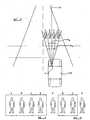
- Figure 3illustrates schematically four pedestrians standing in a roadway in front of the vehicle, identified as pedestrians A, B, C and D.
- pedestrians A, B, C and DWith the relatively wide angular field of view a 1 of the displayed image when the vehicle is stationary or travelling slowly, all four pedestrians are shown in the image presented to the driver of the vehicle by the image display unit 3, as shown in Figure 4 .
- the signal processor 14reduces the angle of the field of view of the image that is presented on the display, whilst simultaneously magnifying the image so that the image still completely fills the display.
- Figure 5only the central pair of pedestrians B and C are illustrated when the vehicle is travelling swiftly, the pedestrians A and D no longer being present in the displayed image.
- the image displayedwill be wide enough to include any cycle tracks, walkways or the like, located at the side of the roadway that the vehicle is driving along, so that the driver of the vehicle may be alerted to potentially dangerous situations, such as pedestrians about to walk into the roadway.
- a relatively narrow field of viewis presented to the driver of the vehicle, showing the roadway in front of the vehicle.
- the signal processor 14electronically processes the signal to select the field of view which is displayed on the display 17. It is to be appreciated, however, that in a modified embodiment of the invention the field of view displayed on the display 17 may be adjusted by altering the focus of the lens 8 using the focusing ring 9, to provide a "optical zoom” effect, so that the optics of the camera are adjusted to ensure that the appropriate image is displayed.
- FIG. 6illustrates a further embodiment of the invention.
- a camera 1 of the type described aboveis mounted in a fixed position on a vehicle 20 with the optical axis 21 of the camera aligned with the longitudinal axis of the vehicle.
- the camerais adapted to receive an optical image over a very wide angular field ⁇ 3.
- the image displayed by the display devicewill be selected so that the image corresponds to a field of view having an angular width ⁇ 1, with that image being centred on the optical axis 21 of the camera.
- Figure 6illustrates the vehicle in a "cornering" situation.
- the steering wheels 22 provided at the front of the vehiclehave been turned so that the rolling direction 23 of the wheel is off-set by an angle ⁇ 4 relative to the initial rolling direction 24 of the wheels 22 when the steering wheels are aligned with the longitudinal axis of the vehicle for straight driving. The vehicle is thus cornering.
- the sensor unit 15senses the angle ⁇ 4 and controls the signal processor 14 so that the image which is displayed by the display unit is off-set from the optical axis 21, so as to display the environment into which the vehicle will move.
- the angle of field of view now displayedis shown as angle ⁇ 5.
- Figure 7illustrates the display, showing that the display only shows the two pedestrians C, D, provided at the end of the row of pedestrians, with the other two pedestrians A, B, not being displayed.
- the field of view that is displayedis determined in accordance with the angular position of the rolling direction of the front steering wheels 22 of the vehicle.
- the field of view that is displayedmay be determined from the driving direction of the vehicle, for example as determined from a GPS sensor.
- the signal processor 14operates so that when the vehicle corners at low speed, the width of the field of view presented on the display increases while the field of view remains aligned with the optical axis 21, whereas when cornering at a higher speed, the overall angular width of the field of view is maintained, but the field of width is off-set from the optical axis 21.
- the angle of off-set from the optical axis 21is preferably equal to the angle ⁇ 4.
Landscapes
- Engineering & Computer Science (AREA)
- Multimedia (AREA)
- Physics & Mathematics (AREA)
- Mechanical Engineering (AREA)
- Signal Processing (AREA)
- Astronomy & Astrophysics (AREA)
- General Physics & Mathematics (AREA)
- Optics & Photonics (AREA)
- Closed-Circuit Television Systems (AREA)
- Traffic Control Systems (AREA)
Abstract
Description
- THE PRESENT INVENTION relates to a night vision device for a vehicle such as a motor vehicle.
- It has been proposed previously to provide a night vision device in a vehicle such as an automobile. The purpose of the night vision device is to enhance the vision of the driver in night conditions.
- Various night vision devices have been proposed before.
US-A-5,414,439 describes a night vision arrangement which utilises a "head-up" display. A motor vehicle is provided with an infra-red camera positioned to view the roadway in front of the vehicle. The camera generates a video signal which is passed to a "head-up" display of the type utilised in combat aircraft. In the embodiment described, the windshield of the motor vehicle or a semi-transmitter is utilised as a combiner to combine the image of the road ahead, as viewed through the windshield by the driver, and a virtual image of the road ahead from an image generator which receives the video signal from the camera. - In
US-A-5,414,439 the infra-red camera is mounted in a fixed position to provide an image of the view in the front of the vehicle. Also the camera has a fixed focal length. Consequently, when cornering the vehicle, that is to say when turning the vehicle to the right or to the left, the camera will always point in a direction aligned with the longitudinal axis of the vehicle. However, there is a need for the driver of the vehicle to view the environment into which the vehicle is moving which will be located either to the left or to the right of the fixed field of view of the camera. JP-A-0 6048247 claim 1 and describes a vehicle mounted infra-red image display arrangement, and in this arrangement the precise field of view that is displayed to the driver of the vehicle is dependent upon the position of the front or steering wheels of the vehicle. However, even in an arrangement such as this, it is difficult to ensure that the appropriate image is displayed, since the field of view that is of interest to the driver is not necessarily aligned with the rolling direction of the steering wheels of the vehicle.JP 09315225 A DE 3,900,667 discloses a video camera mounted to a vehicle which is configured to record an image from outside of the vehicle and transmit it to a display within the vehicle to be viewed by the driver. The video camera is remotely movable by the driver of the vehicle.- When a motor vehicle is being driven quickly, driver of the vehicle tends to concentrate on the road ahead of the vehicle, but, in contrast, when the vehicle is travelling slowly, for example in a built-up area, the driver usually pays attention to situations that may develop on either side of the roadway. Thus the driver may be particularly conscious of pedestrians who are not in the roadway, but who may step into the roadway in front of the vehicle. Thus, when a driver is driving quickly, the driver tends to concentrate on a relatively narrow angular field of view, whereas when the vehicle is driving more slowly, the driver tends to concentrate on a wider angular field of view. If the image provided by a night vision arrangement of the type discussed above were to be utilised to provide the wide field of view, whilst providing a sufficiently large image of the road ahead for fast driving, with a fixed focal length of the lens of the infra-red camera, a very wide display would have to be provided, which may prove to be impractical in many vehicle installations.
- The present invention seeks to provide an improved night vision arrangement.
- According to one aspect of this invention there is provided a night vision arrangement for a vehicle, the night vision arrangement including an infra-red-sensitive camera fixed to the motor vehicle to capture an image of the roadway in front of the vehicle, the image having a predetermined horizontal angular field of view, the camera generating a video signal representing the image, the arrangement further including a display unit adapted to display at least part of the captured image to the driver of the vehicle, characterised in that the arrangement further comprises a signal processing unit adapted to process the video signal, and a sensor unit adapted to sense one or more parameters of the movement of the vehicle, and to provide a control signal, the arrangement being such that, in use, the signal processing unit electronically processes the video signal so that the field of view of the image displayed by the display unit is selected in accordance with the said control signal, wherein the signal processing unit is adapted to process the video signal so that the angular extent of the field of view of the image displayed by the display unit is related to the speed of the vehicle, the sensor being adapted to sense speed, and wherein part of the image captured by the camera is selected for display, that part being selected in dependence upon the direction of movement of the vehicle, the sensor being adapted to sense the direction of movement of the vehicle.
- Conveniently the sensor includes means to sense the rolling direction of the steering wheel relative to the vehicle.
- Advantageously the sensor senses the instantaneous position of the vehicle in a co-ordinate system to derive a signal corresponding to the driving direction and/or speed of the vehicle.
- Preferably the means for sensing the instantaneous position of the vehicle incorporate a GPS sensor arrangement.
- Conveniently the display unit is a monitor which displays an image directly to the vehicle operator.
- Alternatively the display unit is a head-up display unit.
- Preferably the head-up display unit incorporates a mirror for reflecting a virtual image to the driver of the vehicle.
- Conveniently the mirror is a semi-transparent mirror, enabling the operator to view the reflected image and, simultaneously, to see a real image through the mirror.
- In order that the invention may be more readily understood, and so that further features thereof may be appreciated, the invention will now be described, by way of example, with reference to the accompanying drawings in which:
FIGURE 1 is a block schematic view of one embodiment of the invention,FIGURE 2 is a corresponding block schematic view of a second embodiment of the invention,FIGURE 3 is a diagrammatic plan view of a vehicle provided with a night vision arrangement in accordance with the invention,FIGURE 4 is a diagrammatic view of a display provided on the vehicle ofFigure 3 in one condition,FIGURE 5 is a view corresponding toFigure 4 illustrating the display in another condition,FIGURE 6 is a diagrammatic view, corresponding toFigure 3 , of a vehicle provided with another system in accordance with the invention, andFIGURE 7 is a view, corresponding toFigure 4 , showing the display of the embodiment ofFigure 6 .- Referring initially to
Figure 1 of the accompanying drawings, a night vision system for a motor vehicle comprises acamera 1, asignal processing arrangement 2 and a display unit 3. - The
camera 1 is provided with a lens 4. Located behind the lens 4, in alignment with the optical axis of the lens, is abeam deflector 5 which is constituted by an inclined mirror 6. The beam deflector is provided in a hollowtubular neck 7, which contains a focusinglens 8 which may be adjusted by means of a focusing ring 9. Theneck 7 is connected to alower housing 10. Thehousing 10 contains an infra-red sensor element 11, which may be a charge-coupled sensor element, which is mounted on anelectronic unit 12. - It is to be appreciated, therefore, that in use of the
camera 1, the camera will be positioned so that the image viewed by the lens 4 is an image of the roadway in front of the vehicle. The image, after being deflected by thebeam deflector 5, is focussed, by the focusinglens 8, on to the planar infra-red sensor 11. The focus, and thus the field of view, of the camera may be adjusted by a adjusting the focusing ring 9 to provide an "optical zoom" effect in response to a central signal from thesensor 15. - The
camera 1 provides a video output signal on anoutput lead 13. Theoutput lead 13 is connected to asignal processor 14 forming part of thesignal processor arrangement 2. Thesignal processor 14 is connected to receive an input control signal from asensor unit 15. Thesensor unit 15 may be simply a speed sensor adapted to sense the speed of the vehicle. The speed sensor may be connected to the speedometer of the vehicle, or may be connected to a wheel speed sensor forming part of an ABS system. Alternatively, thesensor 15 may be responsive to the position of the front or steering wheels of the vehicle, or an element associated with the steering wheels of the vehicle, such as a tie rod or the steering wheel shaft. Alternatively again, thesensor 15 may be a sensor which can sense the instantaneous position of the vehicle in a co-ordinate system, thus providing signals corresponding to the instantaneous speed and driving direction of the vehicle. Thus, for example, the sensor may be a GPS (Global Positioning System) sensor. The GPS system utilises signals from a number of geo-stadonary satellites which transmit accurate timing system. A GPS sensor processes the signals that it receives from the satellites and can provide very accurate indications as to the position of the sensor. Thus it is envisaged that thesensor 15 may incorporate a GPS sensor to process signals received from the satellite system to determine the position of the vehicle, with thesensor 15 including a processor to determine successive positions of the vehicle and to determine the instantaneous speed and driving direction of the vehicle. - It is thus to be appreciated that the
sensor 15 may include one or more sensors of the types generally discussed above, and thesensor 15 will provide a control signal as an input to thesignal processor 14, that input being indicative of the speed of the vehicle and/or the direction of driving of the vehicle. - The signal processor unit has an output 16 which is connected to an
image generator 17 forming part of the display unit 3. Theimage generator 17 may be a cathode-ray device, or any other conventional form of image generator. Theimage generator 17 is positioned appropriately with regard to a semi-silveredaspherical mirror 18 which forms part of a conventional head-up display unit. Themirror 18 may be mounted on, or may form part of the windshield of a vehicle and may be positioned so that the virtual image that is displayed on themirror 18, from theimage generator 17, as viewed by the driver of the vehicle, is super-imposed on the ordinary view of the roadway in front of the vehicle enjoyed by the driver of the vehicle. - As will be described below, in embodiments of the invention, the
signal processor 14 processes the signal received from thecamera 1, so that the image displayed by the display unit 3 is appropriate, taking into account the speed and/or direction of driving of the vehicle. Figure 2 illustrates an alternative embodiment of the invention. Thecamera 1 and thesignal processing unit 2 are as described above with regard toFigure 1 , and thus these parts of the system will not be re-described. In the embodiment ofFigure 2 , instead of a head-up display unit as described inFigure 1 , a simple monitor orvisual display unit 19 is provided which displays the image obtained from the camera as processed by the signal processing unit. The monitor orvisual display unit 19 will be positioned so as to be readily viewable by the driver of a vehicle.- Referring now to
Figure 3 , avehicle 21 is illustrated schematically from above, and thecamera 1, as described above, is shown mounted in position on a vehicle. The camera is mounted in a fixed position, with the optical axis of the lens 4 aligned with the longitudinal axis of thevehicle 21, so that the camera can capture an infra-red image of the road in front of the vehicle. - In the embodiment of
Figure 3 , thesensor 15 provides a signal to thesignal processor 14 which indicates the speed of the vehicle, and thesignal processor 14 processes the signal representative of the image so that the horizontal width of the field of view of the image displayed is decreased as the speed of the vehicle increases. - When the vehicle is stationary, or travelling at a very slow speed, the
signal processor 14 processes the signal from thecamera 1 so that the display unit 3 displays a very wide image of the roadway in front of the vehicle. This image may have an angular field of view ofα 1, as shown inFigure 3 . - For purposes of explanation,
Figure 3 illustrates schematically four pedestrians standing in a roadway in front of the vehicle, identified as pedestrians A, B, C and D. With the relatively wide angular field of view a 1 of the displayed image when the vehicle is stationary or travelling slowly, all four pedestrians are shown in the image presented to the driver of the vehicle by the image display unit 3, as shown inFigure 4 . - However, as the speed of the vehicle increases, the
signal processor 14 reduces the angle of the field of view of the image that is presented on the display, whilst simultaneously magnifying the image so that the image still completely fills the display. Thus, as shown inFigure 5 , only the central pair of pedestrians B and C are illustrated when the vehicle is travelling swiftly, the pedestrians A and D no longer being present in the displayed image. - It is thus to be appreciated that when the vehicle is travelling slowly, for example in a built-up area, the image displayed will be wide enough to include any cycle tracks, walkways or the like, located at the side of the roadway that the vehicle is driving along, so that the driver of the vehicle may be alerted to potentially dangerous situations, such as pedestrians about to walk into the roadway. However, when the vehicle is travelling swiftly, a relatively narrow field of view is presented to the driver of the vehicle, showing the roadway in front of the vehicle.
- In the embodiment described above, the
signal processor 14 electronically processes the signal to select the field of view which is displayed on thedisplay 17. It is to be appreciated, however, that in a modified embodiment of the invention the field of view displayed on thedisplay 17 may be adjusted by altering the focus of thelens 8 using the focusing ring 9, to provide a "optical zoom" effect, so that the optics of the camera are adjusted to ensure that the appropriate image is displayed. Figure 6 illustrates a further embodiment of the invention. In this embodiment of the invention acamera 1 of the type described above is mounted in a fixed position on avehicle 20 with theoptical axis 21 of the camera aligned with the longitudinal axis of the vehicle.- The camera is adapted to receive an optical image over a very wide angular field α 3. Ordinarily the image displayed by the display device will be selected so that the image corresponds to a field of view having an
angular width α 1, with that image being centred on theoptical axis 21 of the camera. Thus, where four notional pedestrians A, B, C and D are shown standing in front of themotor vehicle 20, all four pedestrians will be within the image displayed by the display unit, if the vehicle is travelling straight. - However,
Figure 6 illustrates the vehicle in a "cornering" situation. Thesteering wheels 22 provided at the front of the vehicle have been turned so that the rollingdirection 23 of the wheel is off-set by an angle α 4 relative to the initial rollingdirection 24 of thewheels 22 when the steering wheels are aligned with the longitudinal axis of the vehicle for straight driving. The vehicle is thus cornering. - The
sensor unit 15, in this embodiment, senses the angle α 4 and controls thesignal processor 14 so that the image which is displayed by the display unit is off-set from theoptical axis 21, so as to display the environment into which the vehicle will move. Thus, the angle of field of view now displayed is shown asangle α 5.Figure 7 illustrates the display, showing that the display only shows the two pedestrians C, D, provided at the end of the row of pedestrians, with the other two pedestrians A, B, not being displayed. - It is thus to be appreciated that, in the embodiment shown in
Figure 6 , the field of view that is displayed is determined in accordance with the angular position of the rolling direction of thefront steering wheels 22 of the vehicle. - In a similar way, the field of view that is displayed may be determined from the driving direction of the vehicle, for example as determined from a GPS sensor.
- It is to be appreciated that various modifications may be effected to the arrangement described above. In one embodiment of the invention, the
signal processor 14 operates so that when the vehicle corners at low speed, the width of the field of view presented on the display increases while the field of view remains aligned with theoptical axis 21, whereas when cornering at a higher speed, the overall angular width of the field of view is maintained, but the field of width is off-set from theoptical axis 21. The angle of off-set from theoptical axis 21 is preferably equal to the angle α 4. - In the present Specification "comprise" means "includes or consists of" and "comprising" means "including or consisting of".
Claims (8)
- A night vision arrangement for a vehicle, the night vision arrangement including an infra-red-sensitive camera (1) fixed to the motor vehicle to capture an image of the roadway in front of the vehicle, the image having a predetermined horizontal angular field of view, the camera (1) generating a video signal representing the image, the arrangement further including a display unit (3) adapted to display at least part of the captured image to the driver of the vehicle,characterised in that the arrangement further comprises a signal processing unit (14) adapted to process the video signal, and a sensor unit (15) adapted to sense one or more parameters of the movement of the vehicle, and to provide a control signal, the arrangement being such that, in use, the signal processing unit (14) electronically processes the video signal so that the field of view (α1, α2) of the image displayed by the display unit (3) is selected in accordance with the said control signal, wherein the signal processing unit (14) is adapted to process the video signal so that the angular extent of the field of view of the image displayed by the display unit (3) is related to the speed of the vehicle, the sensor (15) being adapted to sense speed, and wherein part of the image captured by the camera (1) is selected for display, that part being selected in dependence upon the direction of movement of the vehicle, the sensor (15) being adapted to sense the direction of movement of the vehicle.
- An arrangement according to Claim 1 wherein the sensor (15) includes means to sense the rolling ditection (23) of the steering wheels relative to the vehicle.
- A device according to Claim 1 wherein the sensor (15) senses the instantaneous position of the vehicle in a co-ordinate system to derive a signal corresponding to the driving direction and/or speed of the vehicle.
- A device according to Claim 1 wherein the means for sensing the instantaneous position of the vehicle incorporate a GPS sensor arrangement.
- An arrangement according to any one of the preceding Claims wherein the display unit (3) is a monitor which displays an image directly to the vehicle operator.
- An arrangement according to any one of claims 1 to 4, wherein the display unit is a head-up display unit.
- An arrangement according to Claim 6 wherein the head-up display unit incorporates a mirror (18) for reflecting a virtual image to the driver of the vehicle.
- An arrangement according to Claim 7 wherein the mirror (18) is a semi-transparent mirror, enabling the operator to view the reflected image and, simultaneously, to see a real image through the mirror.
Priority Applications (1)
| Application Number | Priority Date | Filing Date | Title |
|---|---|---|---|
| EP04025960.8AEP1500557B1 (en) | 2000-10-26 | 2001-10-18 | A night vision device for a vehicle |
Applications Claiming Priority (3)
| Application Number | Priority Date | Filing Date | Title |
|---|---|---|---|
| SE0003943ASE520042C2 (en) | 2000-10-26 | 2000-10-26 | Device for improving the night vision of a vehicle such as a car |
| SE0003943 | 2000-10-26 | ||
| PCT/SE2001/002283WO2002036389A1 (en) | 2000-10-26 | 2001-10-18 | A night vision device for a vehicle |
Related Child Applications (1)
| Application Number | Title | Priority Date | Filing Date |
|---|---|---|---|
| EP04025960.8ADivisionEP1500557B1 (en) | 2000-10-26 | 2001-10-18 | A night vision device for a vehicle |
Publications (2)
| Publication Number | Publication Date |
|---|---|
| EP1334008A1 EP1334008A1 (en) | 2003-08-13 |
| EP1334008B1true EP1334008B1 (en) | 2008-07-30 |
Family
ID=20281622
Family Applications (2)
| Application Number | Title | Priority Date | Filing Date |
|---|---|---|---|
| EP01977017AExpired - LifetimeEP1334008B1 (en) | 2000-10-26 | 2001-10-18 | A night vision device for a vehicle |
| EP04025960.8AExpired - LifetimeEP1500557B1 (en) | 2000-10-26 | 2001-10-18 | A night vision device for a vehicle |
Family Applications After (1)
| Application Number | Title | Priority Date | Filing Date |
|---|---|---|---|
| EP04025960.8AExpired - LifetimeEP1500557B1 (en) | 2000-10-26 | 2001-10-18 | A night vision device for a vehicle |
Country Status (7)
| Country | Link |
|---|---|
| US (2) | US20040150515A1 (en) |
| EP (2) | EP1334008B1 (en) |
| JP (1) | JP2004513541A (en) |
| AU (1) | AU2001296167A1 (en) |
| DE (1) | DE60135139D1 (en) |
| SE (1) | SE520042C2 (en) |
| WO (1) | WO2002036389A1 (en) |
Cited By (1)
| Publication number | Priority date | Publication date | Assignee | Title |
|---|---|---|---|---|
| WO2012042355A1 (en)* | 2010-10-01 | 2012-04-05 | Toyota Jidosha Kabushiki Kaisha | Obstacle recognition system and method for a vehicle |
Families Citing this family (37)
| Publication number | Priority date | Publication date | Assignee | Title |
|---|---|---|---|---|
| US20030202097A1 (en) | 2000-10-26 | 2003-10-30 | Autoliv Development Ab | Night vision arrangement |
| SE520042C2 (en)* | 2000-10-26 | 2003-05-13 | Autoliv Dev | Device for improving the night vision of a vehicle such as a car |
| JP4617018B2 (en)* | 2001-04-10 | 2011-01-19 | 本田技研工業株式会社 | Infrared image processing device |
| US7995095B2 (en) | 2001-10-18 | 2011-08-09 | Autoliv Development Ab | Night vision device for a vehicle |
| DE10203413C2 (en)* | 2002-01-28 | 2003-11-27 | Daimler Chrysler Ag | Automobile infrared night vision device |
| DE10227221A1 (en)* | 2002-06-18 | 2004-01-15 | Daimlerchrysler Ag | Method for monitoring the interior or exterior of a vehicle and a vehicle with at least one panoramic camera |
| DE10230202A1 (en)* | 2002-07-05 | 2004-01-15 | Robert Bosch Gmbh | Arrangement to improve visibility |
| DE10247563A1 (en)* | 2002-10-11 | 2004-04-22 | Valeo Schalter Und Sensoren Gmbh | Method and system for assisting the driver |
| DE10249816B4 (en)* | 2002-10-24 | 2006-01-12 | Daimlerchrysler Ag | Method and device for operating an automotive night-vision system |
| DE10250659A1 (en)* | 2002-10-31 | 2004-05-13 | Valeo Schalter Und Sensoren Gmbh | Monitoring device and dome control module |
| DE10253510A1 (en)* | 2002-11-16 | 2004-05-27 | Robert Bosch Gmbh | Visibility improvement device in motor vehicle, has processing unit with arrangement for detecting road profile from acquired optical signal(s) and controlling signaling arrangement accordingly |
| DE10312546B3 (en)* | 2003-03-21 | 2004-09-09 | Audi Ag | Camera control system for road vehicle includes data processing module receiving picture data from camera and passing data onward to displays to help driver |
| DE10336329A1 (en) | 2003-08-07 | 2005-03-10 | Bosch Gmbh Robert | Method and device for improving the visibility in a motor vehicle |
| JP4316960B2 (en)* | 2003-08-22 | 2009-08-19 | 株式会社半導体エネルギー研究所 | apparatus |
| DE10346507B4 (en)* | 2003-10-02 | 2007-10-11 | Daimlerchrysler Ag | Device for improving the visibility in a motor vehicle |
| DE10346511B4 (en)* | 2003-10-02 | 2008-01-31 | Daimler Ag | Device for improving the visibility in a motor vehicle |
| DE10346484B4 (en)* | 2003-10-02 | 2007-10-11 | Daimlerchrysler Ag | Device for improving the visibility in a motor vehicle |
| US6967569B2 (en)* | 2003-10-27 | 2005-11-22 | Ford Global Technologies Llc | Active night vision with adaptive imaging |
| DE10359192A1 (en)* | 2003-12-17 | 2005-07-14 | Hella Kgaa Hueck & Co. | Night vision system for motor vehicle, includes camera which records image in infrared range |
| DE102004026847A1 (en) | 2004-06-02 | 2005-12-22 | Robert Bosch Gmbh | Night vision device for motor vehicles |
| DE102004033625B4 (en) | 2004-07-12 | 2008-12-24 | Continental Automotive Gmbh | Method for displaying the particular front field of view from a motor vehicle |
| DE102004036566A1 (en) | 2004-07-28 | 2006-03-23 | Robert Bosch Gmbh | Night vision device |
| DE102005006287A1 (en) | 2005-02-11 | 2006-08-17 | Bayerische Motoren Werke Ag | Method and device for monitoring the environment of a vehicle |
| FR2898092B1 (en)* | 2006-03-06 | 2009-02-13 | Renault Sas | MIRROR DEVICE FOR MOTOR VEHICLE AND USE OF THE DEVICE |
| DE102008040467A1 (en)* | 2008-07-16 | 2010-01-21 | Robert Bosch Gmbh | Method for improving the view of a driver in a vehicle and arrangement therefor |
| FR2955729B1 (en)* | 2010-01-22 | 2012-12-14 | Valeo Vision | DETECTION METHOD FOR A MOTOR VEHICLE |
| KR102118438B1 (en) | 2013-01-28 | 2020-06-04 | 한국전자통신연구원 | Head up display apparatus for vehicle and method thereof |
| KR102027771B1 (en)* | 2013-01-31 | 2019-10-04 | 한국전자통신연구원 | Obstacle detecting apparatus and method for adaptation to vehicle velocity |
| US9718405B1 (en) | 2015-03-23 | 2017-08-01 | Rosco, Inc. | Collision avoidance and/or pedestrian detection system |
| US9888174B2 (en) | 2015-10-15 | 2018-02-06 | Microsoft Technology Licensing, Llc | Omnidirectional camera with movement detection |
| US10277858B2 (en) | 2015-10-29 | 2019-04-30 | Microsoft Technology Licensing, Llc | Tracking object of interest in an omnidirectional video |
| US10469758B2 (en) | 2016-12-06 | 2019-11-05 | Microsoft Technology Licensing, Llc | Structured light 3D sensors with variable focal length lenses and illuminators |
| US10554881B2 (en) | 2016-12-06 | 2020-02-04 | Microsoft Technology Licensing, Llc | Passive and active stereo vision 3D sensors with variable focal length lenses |
| KR102022589B1 (en)* | 2017-10-17 | 2019-09-18 | 국방과학연구소 | The method for calculating ambiguity probability of the direction of arrival |
| WO2019124056A1 (en) | 2017-12-18 | 2019-06-27 | キヤノン株式会社 | Imaging device, method for controlling same, program, and storage medium |
| JP7233162B2 (en) | 2017-12-18 | 2023-03-06 | キヤノン株式会社 | IMAGING DEVICE AND CONTROL METHOD THEREOF, PROGRAM, STORAGE MEDIUM |
| US12115916B2 (en) | 2021-02-01 | 2024-10-15 | Rosco, Inc. | Downlighting signal and illumination mirror head for vehicle |
Family Cites Families (23)
| Publication number | Priority date | Publication date | Assignee | Title |
|---|---|---|---|---|
| DE3900667A1 (en)* | 1989-01-09 | 1990-07-12 | Fahri Kirsever | Periscope for a motor vehicle |
| JP3419802B2 (en)* | 1992-08-03 | 2003-06-23 | 富士通株式会社 | In-vehicle infrared image display |
| JP2783079B2 (en)* | 1992-08-28 | 1998-08-06 | トヨタ自動車株式会社 | Light distribution control device for headlamp |
| JP3259475B2 (en)* | 1993-10-27 | 2002-02-25 | ミノルタ株式会社 | Distance measuring device |
| US5473364A (en)* | 1994-06-03 | 1995-12-05 | David Sarnoff Research Center, Inc. | Video technique for indicating moving objects from a movable platform |
| US5414439A (en) | 1994-06-09 | 1995-05-09 | Delco Electronics Corporation | Head up display with night vision enhancement |
| KR960032262A (en)* | 1995-02-09 | 1996-09-17 | 배순훈 | Vehicle safety system |
| JPH09315225A (en)* | 1996-05-27 | 1997-12-09 | Kobe Steel Ltd | On-vehicle infrared image display device |
| US6550949B1 (en)* | 1996-06-13 | 2003-04-22 | Gentex Corporation | Systems and components for enhancing rear vision from a vehicle |
| DE29621172U1 (en)* | 1996-12-06 | 1998-04-09 | Hohe GmbH & Co. KG, 97903 Collenberg | Outside mirror with extended viewing angle |
| FR2785434B1 (en)* | 1998-11-03 | 2003-05-16 | Renault | METHOD FOR ASSISTING THE DRIVING OF A VEHICLE AND DEVICE FOR IMPLEMENTING IT |
| JP3864406B2 (en)* | 1999-01-26 | 2006-12-27 | マツダ株式会社 | Vehicle display device |
| JP3298851B2 (en)* | 1999-08-18 | 2002-07-08 | 松下電器産業株式会社 | Multi-function vehicle camera system and image display method of multi-function vehicle camera |
| DE19940723A1 (en)* | 1999-08-27 | 2001-03-08 | Daimler Chrysler Ag | Method for displaying a perspective image and display device for at least one occupant of a vehicle |
| DE19945588A1 (en)* | 1999-09-23 | 2001-04-19 | Bayerische Motoren Werke Ag | Sensor arrangement |
| DE19950033B4 (en)* | 1999-10-16 | 2005-03-03 | Bayerische Motoren Werke Ag | Camera device for vehicles |
| JP2001150977A (en)* | 1999-11-25 | 2001-06-05 | Mazda Motor Corp | Vehicle display device |
| US6977630B1 (en)* | 2000-07-18 | 2005-12-20 | University Of Minnesota | Mobility assist device |
| US6897892B2 (en)* | 2000-10-13 | 2005-05-24 | Alexander L. Kormos | System and method for forming images for display in a vehicle |
| SE520042C2 (en)* | 2000-10-26 | 2003-05-13 | Autoliv Dev | Device for improving the night vision of a vehicle such as a car |
| US20020067413A1 (en)* | 2000-12-04 | 2002-06-06 | Mcnamara Dennis Patrick | Vehicle night vision system |
| US6384741B1 (en)* | 2001-01-16 | 2002-05-07 | O'leary, Sr. Jerry P. | Apparatus and method for providing high mounted view of traffic |
| US20030095688A1 (en)* | 2001-10-30 | 2003-05-22 | Kirmuss Charles Bruno | Mobile motor vehicle identification |
- 2000
- 2000-10-26SESE0003943Apatent/SE520042C2/enunknown
- 2001
- 2001-10-18DEDE60135139Tpatent/DE60135139D1/ennot_activeExpired - Lifetime
- 2001-10-18JPJP2002539171Apatent/JP2004513541A/enactivePending
- 2001-10-18WOPCT/SE2001/002283patent/WO2002036389A1/enactiveApplication Filing
- 2001-10-18EPEP01977017Apatent/EP1334008B1/ennot_activeExpired - Lifetime
- 2001-10-18EPEP04025960.8Apatent/EP1500557B1/ennot_activeExpired - Lifetime
- 2001-10-18AUAU2001296167Apatent/AU2001296167A1/ennot_activeAbandoned
- 2003
- 2003-04-25USUS10/423,054patent/US20040150515A1/ennot_activeAbandoned
- 2003-12-31USUS10/753,191patent/US20040227083A1/ennot_activeAbandoned
Cited By (4)
| Publication number | Priority date | Publication date | Assignee | Title |
|---|---|---|---|---|
| WO2012042355A1 (en)* | 2010-10-01 | 2012-04-05 | Toyota Jidosha Kabushiki Kaisha | Obstacle recognition system and method for a vehicle |
| CN103153743A (en)* | 2010-10-01 | 2013-06-12 | 丰田自动车株式会社 | Obstacle recognition system and method for a vehicle |
| US8941479B2 (en) | 2010-10-01 | 2015-01-27 | Toyota Jidosha Kabushiki Kaisha | Obstacle recognition system and method for a vehicle |
| CN103153743B (en)* | 2010-10-01 | 2016-08-03 | 丰田自动车株式会社 | Differentiating obstacle and method for vehicle |
Also Published As
| Publication number | Publication date |
|---|---|
| US20040150515A1 (en) | 2004-08-05 |
| SE0003943L (en) | 2002-06-19 |
| SE0003943D0 (en) | 2000-10-26 |
| EP1500557B1 (en) | 2013-12-25 |
| WO2002036389A1 (en) | 2002-05-10 |
| DE60135139D1 (en) | 2008-09-11 |
| JP2004513541A (en) | 2004-04-30 |
| US20040227083A1 (en) | 2004-11-18 |
| AU2001296167A1 (en) | 2002-05-15 |
| EP1334008A1 (en) | 2003-08-13 |
| SE520042C2 (en) | 2003-05-13 |
| EP1500557A1 (en) | 2005-01-26 |
Similar Documents
| Publication | Publication Date | Title |
|---|---|---|
| EP1334008B1 (en) | A night vision device for a vehicle | |
| US7995095B2 (en) | Night vision device for a vehicle | |
| JP4855158B2 (en) | Driving assistance device | |
| US7605773B2 (en) | Head-up display system and method for carrying out the location-correct display of an object situated outside a vehicle with regard to the position of the driver | |
| JP5117003B2 (en) | Driving assistance device | |
| US6967569B2 (en) | Active night vision with adaptive imaging | |
| US10558221B2 (en) | Method for assisting in a parking operation for a motor vehicle, driver assistance system and a motor vehicle | |
| US8031225B2 (en) | Surroundings monitoring system for a vehicle | |
| US8164627B1 (en) | Camera system for vehicles | |
| US5949331A (en) | Display enhancements for vehicle vision system | |
| US8035575B2 (en) | Driving support method and driving support apparatus | |
| JP3034409B2 (en) | Rear image display device | |
| JP5099451B2 (en) | Vehicle periphery confirmation device | |
| US20110181728A1 (en) | Electronic side view display system | |
| US20090195414A1 (en) | Night Vision Device | |
| JP4948115B2 (en) | Rear view device | |
| EP2687408B1 (en) | Vehicle periphery monitoring device | |
| JP2005186648A (en) | Vehicle periphery visual recognition device and display control device | |
| JPH08253059A (en) | Vehicle driving support system | |
| CN111655541A (en) | Driver assistance system for an industrial vehicle | |
| EP2246762B1 (en) | System and method for driving assistance at road intersections | |
| JP3988551B2 (en) | Vehicle perimeter monitoring device | |
| US20060268006A1 (en) | Display device for vehicle | |
| JPH09180088A (en) | Surrounding monitor device for vehicles | |
| JP2009149306A (en) | Vehicular display device |
Legal Events
| Date | Code | Title | Description |
|---|---|---|---|
| PUAI | Public reference made under article 153(3) epc to a published international application that has entered the european phase | Free format text:ORIGINAL CODE: 0009012 | |
| 17P | Request for examination filed | Effective date:20030502 | |
| AK | Designated contracting states | Designated state(s):AT BE CH CY DE DK ES FI FR GB GR IE IT LI LU MC NL PT SE TR | |
| RBV | Designated contracting states (corrected) | Designated state(s):AT BE CH DE FR GB LI | |
| 17Q | First examination report despatched | Effective date:20040525 | |
| 19A | Proceedings stayed before grant | Effective date:20041214 | |
| 19F | Resumption of proceedings before grant (after stay of proceedings) | Effective date:20070702 | |
| RAP1 | Party data changed (applicant data changed or rights of an application transferred) | Owner name:AUTOLIV DEVELOPMENT AKTIEBOLAG Owner name:FLIR SYSTEMS, INC | |
| GRAP | Despatch of communication of intention to grant a patent | Free format text:ORIGINAL CODE: EPIDOSNIGR1 | |
| RBV | Designated contracting states (corrected) | Designated state(s):DE FR GB | |
| GRAS | Grant fee paid | Free format text:ORIGINAL CODE: EPIDOSNIGR3 | |
| GRAA | (expected) grant | Free format text:ORIGINAL CODE: 0009210 | |
| AK | Designated contracting states | Kind code of ref document:B1 Designated state(s):DE FR GB | |
| REG | Reference to a national code | Ref country code:GB Ref legal event code:FG4D | |
| REF | Corresponds to: | Ref document number:60135139 Country of ref document:DE Date of ref document:20080911 Kind code of ref document:P | |
| PLBE | No opposition filed within time limit | Free format text:ORIGINAL CODE: 0009261 | |
| STAA | Information on the status of an ep patent application or granted ep patent | Free format text:STATUS: NO OPPOSITION FILED WITHIN TIME LIMIT | |
| 26N | No opposition filed | Effective date:20090506 | |
| PGFP | Annual fee paid to national office [announced via postgrant information from national office to epo] | Ref country code:GB Payment date:20090827 Year of fee payment:9 | |
| GBPC | Gb: european patent ceased through non-payment of renewal fee | Effective date:20101018 | |
| PG25 | Lapsed in a contracting state [announced via postgrant information from national office to epo] | Ref country code:GB Free format text:LAPSE BECAUSE OF NON-PAYMENT OF DUE FEES Effective date:20101018 | |
| REG | Reference to a national code | Ref country code:FR Ref legal event code:PLFP Year of fee payment:15 | |
| REG | Reference to a national code | Ref country code:FR Ref legal event code:PLFP Year of fee payment:16 | |
| REG | Reference to a national code | Ref country code:FR Ref legal event code:PLFP Year of fee payment:17 | |
| REG | Reference to a national code | Ref country code:FR Ref legal event code:PLFP Year of fee payment:18 | |
| PGFP | Annual fee paid to national office [announced via postgrant information from national office to epo] | Ref country code:DE Payment date:20181004 Year of fee payment:18 | |
| PGFP | Annual fee paid to national office [announced via postgrant information from national office to epo] | Ref country code:FR Payment date:20181010 Year of fee payment:18 | |
| REG | Reference to a national code | Ref country code:DE Ref legal event code:R119 Ref document number:60135139 Country of ref document:DE | |
| PG25 | Lapsed in a contracting state [announced via postgrant information from national office to epo] | Ref country code:DE Free format text:LAPSE BECAUSE OF NON-PAYMENT OF DUE FEES Effective date:20200501 | |
| PG25 | Lapsed in a contracting state [announced via postgrant information from national office to epo] | Ref country code:FR Free format text:LAPSE BECAUSE OF NON-PAYMENT OF DUE FEES Effective date:20191031 |