EP1332724B1 - Radio frequency pulmonary vein isolation - Google Patents
Radio frequency pulmonary vein isolationDownload PDFInfo
- Publication number
- EP1332724B1 EP1332724B1EP03250562AEP03250562AEP1332724B1EP 1332724 B1EP1332724 B1EP 1332724B1EP 03250562 AEP03250562 AEP 03250562AEP 03250562 AEP03250562 AEP 03250562AEP 1332724 B1EP1332724 B1EP 1332724B1
- Authority
- EP
- European Patent Office
- Prior art keywords
- coil
- pulmonary vein
- heating
- catheter
- radially
- Prior art date
- Legal status (The legal status is an assumption and is not a legal conclusion. Google has not performed a legal analysis and makes no representation as to the accuracy of the status listed.)
- Expired - Lifetime
Links
- 210000003492pulmonary veinAnatomy0.000titleabstractdescription64
- 238000002955isolationMethods0.000titledescription11
- 238000010438heat treatmentMethods0.000claimsdescription21
- 239000000463materialSubstances0.000claimsdescription6
- 229910001285shape-memory alloyInorganic materials0.000claimsdescription6
- 238000004804windingMethods0.000claimsdescription4
- 239000002826coolantSubstances0.000claimsdescription3
- 230000001939inductive effectEffects0.000claimsdescription3
- 238000002679ablationMethods0.000abstractdescription23
- 238000004873anchoringMethods0.000abstractdescription22
- 230000003902lesionEffects0.000abstractdescription10
- 210000005246left atriumAnatomy0.000abstractdescription7
- 230000002107myocardial effectEffects0.000abstract1
- 238000000034methodMethods0.000description42
- 210000001519tissueAnatomy0.000description16
- 238000013507mappingMethods0.000description11
- 230000001746atrial effectEffects0.000description7
- 230000000694effectsEffects0.000description7
- 239000012530fluidSubstances0.000description7
- 238000013459approachMethods0.000description5
- 230000005672electromagnetic fieldEffects0.000description5
- 238000007674radiofrequency ablationMethods0.000description5
- RJURFGZVJUQBHK-UHFFFAOYSA-Nactinomycin DNatural productsCC1OC(=O)C(C(C)C)N(C)C(=O)CN(C)C(=O)C2CCCN2C(=O)C(C(C)C)NC(=O)C1NC(=O)C1=C(N)C(=O)C(C)=C2OC(C(C)=CC=C3C(=O)NC4C(=O)NC(C(N5CCCC5C(=O)N(C)CC(=O)N(C)C(C(C)C)C(=O)OC4C)=O)C(C)C)=C3N=C21RJURFGZVJUQBHK-UHFFFAOYSA-N0.000description4
- 210000004971interatrial septumAnatomy0.000description4
- 238000012544monitoring processMethods0.000description4
- 238000011282treatmentMethods0.000description4
- 238000002604ultrasonographyMethods0.000description4
- 206010003130Arrhythmia supraventricularDiseases0.000description3
- DCXYFEDJOCDNAF-REOHCLBHSA-NL-asparagineChemical compoundOC(=O)[C@@H](N)CC(N)=ODCXYFEDJOCDNAF-REOHCLBHSA-N0.000description3
- FAPWRFPIFSIZLT-UHFFFAOYSA-MSodium chlorideChemical compound[Na+].[Cl-]FAPWRFPIFSIZLT-UHFFFAOYSA-M0.000description3
- 230000002159abnormal effectEffects0.000description3
- 230000001028anti-proliverative effectEffects0.000description3
- 239000003795chemical substances by applicationSubstances0.000description3
- 238000011065in-situ storageMethods0.000description3
- 239000003112inhibitorSubstances0.000description3
- 230000004807localizationEffects0.000description3
- 239000011780sodium chlorideSubstances0.000description3
- 210000001835visceraAnatomy0.000description3
- BSYNRYMUTXBXSQ-UHFFFAOYSA-NAspirinChemical compoundCC(=O)OC1=CC=CC=C1C(O)=OBSYNRYMUTXBXSQ-UHFFFAOYSA-N0.000description2
- IJGRMHOSHXDMSA-UHFFFAOYSA-NAtomic nitrogenChemical compoundN#NIJGRMHOSHXDMSA-UHFFFAOYSA-N0.000description2
- 206010003658Atrial FibrillationDiseases0.000description2
- DLGOEMSEDOSKAD-UHFFFAOYSA-NCarmustineChemical compoundClCCNC(=O)N(N=O)CCClDLGOEMSEDOSKAD-UHFFFAOYSA-N0.000description2
- PTOAARAWEBMLNO-KVQBGUIXSA-NCladribineChemical compoundC1=NC=2C(N)=NC(Cl)=NC=2N1[C@H]1C[C@H](O)[C@@H](CO)O1PTOAARAWEBMLNO-KVQBGUIXSA-N0.000description2
- 108010092160DactinomycinProteins0.000description2
- AOJJSUZBOXZQNB-TZSSRYMLSA-NDoxorubicinChemical compoundO([C@H]1C[C@@](O)(CC=2C(O)=C3C(=O)C=4C=CC=C(C=4C(=O)C3=C(O)C=21)OC)C(=O)CO)[C@H]1C[C@H](N)[C@H](O)[C@H](C)O1AOJJSUZBOXZQNB-TZSSRYMLSA-N0.000description2
- 108050007372Fibroblast Growth FactorProteins0.000description2
- 102000018233Fibroblast Growth FactorHuman genes0.000description2
- HTTJABKRGRZYRN-UHFFFAOYSA-NHeparinChemical compoundOC1C(NC(=O)C)C(O)OC(COS(O)(=O)=O)C1OC1C(OS(O)(=O)=O)C(O)C(OC2C(C(OS(O)(=O)=O)C(OC3C(C(O)C(O)C(O3)C(O)=O)OS(O)(=O)=O)C(CO)O2)NS(O)(=O)=O)C(C(O)=O)O1HTTJABKRGRZYRN-UHFFFAOYSA-N0.000description2
- SIKJAQJRHWYJAI-UHFFFAOYSA-NIndoleChemical compoundC1=CC=C2NC=CC2=C1SIKJAQJRHWYJAI-UHFFFAOYSA-N0.000description2
- 208000031481Pathologic ConstrictionDiseases0.000description2
- 108010073929Vascular Endothelial Growth Factor AProteins0.000description2
- 102000005789Vascular Endothelial Growth FactorsHuman genes0.000description2
- 108010019530Vascular Endothelial Growth FactorsProteins0.000description2
- 229960001138acetylsalicylic acidDrugs0.000description2
- 239000002253acidSubstances0.000description2
- 150000007513acidsChemical class0.000description2
- RJURFGZVJUQBHK-IIXSONLDSA-Nactinomycin DChemical compoundC[C@H]1OC(=O)[C@H](C(C)C)N(C)C(=O)CN(C)C(=O)[C@@H]2CCCN2C(=O)[C@@H](C(C)C)NC(=O)[C@H]1NC(=O)C1=C(N)C(=O)C(C)=C2OC(C(C)=CC=C3C(=O)N[C@@H]4C(=O)N[C@@H](C(N5CCC[C@H]5C(=O)N(C)CC(=O)N(C)[C@@H](C(C)C)C(=O)O[C@@H]4C)=O)C(C)C)=C3N=C21RJURFGZVJUQBHK-IIXSONLDSA-N0.000description2
- 229910045601alloyInorganic materials0.000description2
- 239000000956alloySubstances0.000description2
- 230000002927anti-mitotic effectEffects0.000description2
- 206010003119arrhythmiaDiseases0.000description2
- 229960001230asparagineDrugs0.000description2
- 230000008901benefitEffects0.000description2
- 239000008280bloodSubstances0.000description2
- 210000004369bloodAnatomy0.000description2
- 230000008602contractionEffects0.000description2
- 238000001816coolingMethods0.000description2
- 229960000640dactinomycinDrugs0.000description2
- 229940126864fibroblast growth factorDrugs0.000description2
- JYGXADMDTFJGBT-VWUMJDOOSA-NhydrocortisoneChemical compoundO=C1CC[C@]2(C)[C@H]3[C@@H](O)C[C@](C)([C@@](CC4)(O)C(=O)CO)[C@@H]4[C@@H]3CCC2=C1JYGXADMDTFJGBT-VWUMJDOOSA-N0.000description2
- CGIGDMFJXJATDK-UHFFFAOYSA-NindomethacinChemical compoundCC1=C(CC(O)=O)C2=CC(OC)=CC=C2N1C(=O)C1=CC=C(Cl)C=C1CGIGDMFJXJATDK-UHFFFAOYSA-N0.000description2
- 238000004519manufacturing processMethods0.000description2
- CFCUWKMKBJTWLW-BKHRDMLASA-NmithramycinChemical compoundO([C@@H]1C[C@@H](O[C@H](C)[C@H]1O)OC=1C=C2C=C3C[C@H]([C@@H](C(=O)C3=C(O)C2=C(O)C=1C)O[C@@H]1O[C@H](C)[C@@H](O)[C@H](O[C@@H]2O[C@H](C)[C@H](O)[C@H](O[C@@H]3O[C@H](C)[C@@H](O)[C@@](C)(O)C3)C2)C1)[C@H](OC)C(=O)[C@@H](O)[C@@H](C)O)[C@H]1C[C@@H](O)[C@H](O)[C@@H](C)O1CFCUWKMKBJTWLW-BKHRDMLASA-N0.000description2
- 229910001000nickel titaniumInorganic materials0.000description2
- 230000010412perfusionEffects0.000description2
- BASFCYQUMIYNBI-UHFFFAOYSA-NplatinumChemical compound[Pt]BASFCYQUMIYNBI-UHFFFAOYSA-N0.000description2
- 229960003171plicamycinDrugs0.000description2
- 229920000642polymerPolymers0.000description2
- ZAHRKKWIAAJSAO-UHFFFAOYSA-NrapamycinNatural productsCOCC(O)C(=C/C(C)C(=O)CC(OC(=O)C1CCCCN1C(=O)C(=O)C2(O)OC(CC(OC)C(=CC=CC=CC(C)CC(C)C(=O)C)C)CCC2C)C(C)CC3CCC(O)C(C3)OC)CZAHRKKWIAAJSAO-UHFFFAOYSA-N0.000description2
- 229960002930sirolimusDrugs0.000description2
- QFJCIRLUMZQUOT-HPLJOQBZSA-NsirolimusChemical compoundC1C[C@@H](O)[C@H](OC)C[C@@H]1C[C@@H](C)[C@H]1OC(=O)[C@@H]2CCCCN2C(=O)C(=O)[C@](O)(O2)[C@H](C)CC[C@H]2C[C@H](OC)/C(C)=C/C=C/C=C/[C@@H](C)C[C@@H](C)C(=O)[C@H](OC)[C@H](O)/C(C)=C/[C@@H](C)C(=O)C1QFJCIRLUMZQUOT-HPLJOQBZSA-N0.000description2
- 230000036262stenosisEffects0.000description2
- 208000037804stenosisDiseases0.000description2
- 230000001225therapeutic effectEffects0.000description2
- WYWHKKSPHMUBEB-UHFFFAOYSA-NtioguanineChemical compoundN1C(N)=NC(=S)C2=C1N=CN2WYWHKKSPHMUBEB-UHFFFAOYSA-N0.000description2
- 230000009466transformationEffects0.000description2
- 229910000859α-FeInorganic materials0.000description2
- FPVKHBSQESCIEP-UHFFFAOYSA-N(8S)-3-(2-deoxy-beta-D-erythro-pentofuranosyl)-3,6,7,8-tetrahydroimidazo[4,5-d][1,3]diazepin-8-olNatural productsC1C(O)C(CO)OC1N1C(NC=NCC2O)=C2N=C1FPVKHBSQESCIEP-UHFFFAOYSA-N0.000description1
- FDKXTQMXEQVLRF-ZHACJKMWSA-N(E)-dacarbazineChemical compoundCN(C)\N=N\c1[nH]cnc1C(N)=OFDKXTQMXEQVLRF-ZHACJKMWSA-N0.000description1
- 1021000255731-alkyl-2-acetylglycerophosphocholine esteraseHuman genes0.000description1
- VSNHCAURESNICA-NJFSPNSNSA-N1-oxidanylureaChemical compoundN[14C](=O)NOVSNHCAURESNICA-NJFSPNSNSA-N0.000description1
- FUFLCEKSBBHCMO-UHFFFAOYSA-N11-dehydrocorticosteroneNatural productsO=C1CCC2(C)C3C(=O)CC(C)(C(CC4)C(=O)CO)C4C3CCC2=C1FUFLCEKSBBHCMO-UHFFFAOYSA-N0.000description1
- CTRPRMNBTVRDFH-UHFFFAOYSA-N2-n-methyl-1,3,5-triazine-2,4,6-triamineChemical classCNC1=NC(N)=NC(N)=N1CTRPRMNBTVRDFH-UHFFFAOYSA-N0.000description1
- PLIKAWJENQZMHA-UHFFFAOYSA-N4-aminophenolChemical classNC1=CC=C(O)C=C1PLIKAWJENQZMHA-UHFFFAOYSA-N0.000description1
- VHRSUDSXCMQTMA-PJHHCJLFSA-N6alpha-methylprednisoloneChemical compoundC([C@@]12C)=CC(=O)C=C1[C@@H](C)C[C@@H]1[C@@H]2[C@@H](O)C[C@]2(C)[C@@](O)(C(=O)CO)CC[C@H]21VHRSUDSXCMQTMA-PJHHCJLFSA-N0.000description1
- STQGQHZAVUOBTE-UHFFFAOYSA-N7-Cyan-hept-2t-en-4,6-diinsaeureNatural productsC1=2C(O)=C3C(=O)C=4C(OC)=CC=CC=4C(=O)C3=C(O)C=2CC(O)(C(C)=O)CC1OC1CC(N)C(O)C(C)O1STQGQHZAVUOBTE-UHFFFAOYSA-N0.000description1
- RZVAJINKPMORJF-UHFFFAOYSA-NAcetaminophenChemical compoundCC(=O)NC1=CC=C(O)C=C1RZVAJINKPMORJF-UHFFFAOYSA-N0.000description1
- 108010024976AsparaginaseProteins0.000description1
- DCXYFEDJOCDNAF-UHFFFAOYSA-NAsparagineNatural productsOC(=O)C(N)CC(N)=ODCXYFEDJOCDNAF-UHFFFAOYSA-N0.000description1
- XHVAWZZCDCWGBK-WYRLRVFGSA-MAurothioglucoseChemical compoundOC[C@H]1O[C@H](S[Au])[C@H](O)[C@@H](O)[C@@H]1OXHVAWZZCDCWGBK-WYRLRVFGSA-M0.000description1
- NOWKCMXCCJGMRR-UHFFFAOYSA-NAziridineChemical classC1CN1NOWKCMXCCJGMRR-UHFFFAOYSA-N0.000description1
- 239000005552B01AC04 - ClopidogrelSubstances0.000description1
- 239000005528B01AC05 - TiclopidineSubstances0.000description1
- 108010006654BleomycinProteins0.000description1
- 229940123587Cell cycle inhibitorDrugs0.000description1
- JWBOIMRXGHLCPP-UHFFFAOYSA-NChloditanChemical compoundC=1C=CC=C(Cl)C=1C(C(Cl)Cl)C1=CC=C(Cl)C=C1JWBOIMRXGHLCPP-UHFFFAOYSA-N0.000description1
- MFYSYFVPBJMHGN-UHFFFAOYSA-NCortisoneNatural productsO=C1CCC2(C)C3C(=O)CC(C)(C(CC4)(O)C(=O)CO)C4C3CCC2=C1MFYSYFVPBJMHGN-UHFFFAOYSA-N0.000description1
- MFYSYFVPBJMHGN-ZPOLXVRWSA-NCortisoneChemical compoundO=C1CC[C@]2(C)[C@H]3C(=O)C[C@](C)([C@@](CC4)(O)C(=O)CO)[C@@H]4[C@@H]3CCC2=C1MFYSYFVPBJMHGN-ZPOLXVRWSA-N0.000description1
- CMSMOCZEIVJLDB-UHFFFAOYSA-NCyclophosphamideChemical compoundClCCN(CCCl)P1(=O)NCCCO1CMSMOCZEIVJLDB-UHFFFAOYSA-N0.000description1
- PMATZTZNYRCHOR-CGLBZJNRSA-NCyclosporin AChemical compoundCC[C@@H]1NC(=O)[C@H]([C@H](O)[C@H](C)C\C=C\C)N(C)C(=O)[C@H](C(C)C)N(C)C(=O)[C@H](CC(C)C)N(C)C(=O)[C@H](CC(C)C)N(C)C(=O)[C@@H](C)NC(=O)[C@H](C)NC(=O)[C@H](CC(C)C)N(C)C(=O)[C@H](C(C)C)NC(=O)[C@H](CC(C)C)N(C)C(=O)CN(C)C1=OPMATZTZNYRCHOR-CGLBZJNRSA-N0.000description1
- 108010036949CyclosporineProteins0.000description1
- UHDGCWIWMRVCDJ-CCXZUQQUSA-NCytarabineChemical compoundO=C1N=C(N)C=CN1[C@H]1[C@@H](O)[C@H](O)[C@@H](CO)O1UHDGCWIWMRVCDJ-CCXZUQQUSA-N0.000description1
- 108090000790EnzymesProteins0.000description1
- 102000004190EnzymesHuman genes0.000description1
- GHASVSINZRGABV-UHFFFAOYSA-NFluorouracilChemical compoundFC1=CNC(=O)NC1=OGHASVSINZRGABV-UHFFFAOYSA-N0.000description1
- HEFNNWSXXWATRW-UHFFFAOYSA-NIbuprofenChemical compoundCC(C)CC1=CC=C(C(C)C(O)=O)C=C1HEFNNWSXXWATRW-UHFFFAOYSA-N0.000description1
- XDXDZDZNSLXDNA-UHFFFAOYSA-NIdarubicinNatural productsC1C(N)C(O)C(C)OC1OC1C2=C(O)C(C(=O)C3=CC=CC=C3C3=O)=C3C(O)=C2CC(O)(C(C)=O)C1XDXDZDZNSLXDNA-UHFFFAOYSA-N0.000description1
- XDXDZDZNSLXDNA-TZNDIEGXSA-NIdarubicinChemical compoundC1[C@H](N)[C@H](O)[C@H](C)O[C@H]1O[C@@H]1C2=C(O)C(C(=O)C3=CC=CC=C3C3=O)=C3C(O)=C2C[C@@](O)(C(C)=O)C1XDXDZDZNSLXDNA-TZNDIEGXSA-N0.000description1
- 102100022337Integrin alpha-VHuman genes0.000description1
- FBOZXECLQNJBKD-ZDUSSCGKSA-NL-methotrexateChemical compoundC=1N=C2N=C(N)N=C(N)C2=NC=1CN(C)C1=CC=C(C(=O)N[C@@H](CCC(O)=O)C(O)=O)C=C1FBOZXECLQNJBKD-ZDUSSCGKSA-N0.000description1
- SBDNJUWAMKYJOX-UHFFFAOYSA-NMeclofenamic AcidChemical compoundCC1=CC=C(Cl)C(NC=2C(=CC=CC=2)C(O)=O)=C1ClSBDNJUWAMKYJOX-UHFFFAOYSA-N0.000description1
- 229930192392MitomycinNatural products0.000description1
- 206010062575Muscle contractureDiseases0.000description1
- NWIBSHFKIJFRCO-WUDYKRTCSA-NMytomycinChemical compoundC1N2C(C(C(C)=C(N)C3=O)=O)=C3[C@@H](COC(N)=O)[C@@]2(OC)[C@@H]2[C@H]1N2NWIBSHFKIJFRCO-WUDYKRTCSA-N0.000description1
- BLXXJMDCKKHMKV-UHFFFAOYSA-NNabumetoneChemical compoundC1=C(CCC(C)=O)C=CC2=CC(OC)=CC=C21BLXXJMDCKKHMKV-UHFFFAOYSA-N0.000description1
- MWUXSHHQAYIFBG-UHFFFAOYSA-NNitric oxideChemical classO=[N]MWUXSHHQAYIFBG-UHFFFAOYSA-N0.000description1
- 229930012538PaclitaxelNatural products0.000description1
- 108010023197StreptokinaseProteins0.000description1
- 208000001871TachycardiaDiseases0.000description1
- QJJXYPPXXYFBGM-LFZNUXCKSA-NTacrolimusChemical compoundC1C[C@@H](O)[C@H](OC)C[C@@H]1\C=C(/C)[C@@H]1[C@H](C)[C@@H](O)CC(=O)[C@H](CC=C)/C=C(C)/C[C@H](C)C[C@H](OC)[C@H]([C@H](C[C@H]2C)OC)O[C@@]2(O)C(=O)C(=O)N2CCCC[C@H]2C(=O)O1QJJXYPPXXYFBGM-LFZNUXCKSA-N0.000description1
- FOCVUCIESVLUNU-UHFFFAOYSA-NThiotepaChemical compoundC1CN1P(N1CC1)(=S)N1CC1FOCVUCIESVLUNU-UHFFFAOYSA-N0.000description1
- 108090000190ThrombinProteins0.000description1
- 108090000373Tissue Plasminogen ActivatorProteins0.000description1
- 102000003978Tissue Plasminogen ActivatorHuman genes0.000description1
- 108090000435Urokinase-type plasminogen activatorProteins0.000description1
- 102000003990Urokinase-type plasminogen activatorHuman genes0.000description1
- JXLYSJRDGCGARV-WWYNWVTFSA-NVinblastineNatural productsO=C(O[C@H]1[C@](O)(C(=O)OC)[C@@H]2N(C)c3c(cc(c(OC)c3)[C@]3(C(=O)OC)c4[nH]c5c(c4CCN4C[C@](O)(CC)C[C@H](C3)C4)cccc5)[C@@]32[C@H]2[C@@]1(CC)C=CCN2CC3)CJXLYSJRDGCGARV-WWYNWVTFSA-N0.000description1
- 229940122803Vinca alkaloidDrugs0.000description1
- 108010048673Vitronectin ReceptorsProteins0.000description1
- HZEWFHLRYVTOIW-UHFFFAOYSA-N[Ti].[Ni]Chemical compound[Ti].[Ni]HZEWFHLRYVTOIW-UHFFFAOYSA-N0.000description1
- 229960000446abciximabDrugs0.000description1
- 230000001594aberrant effectEffects0.000description1
- 238000010317ablation therapyMethods0.000description1
- 235000011054acetic acidNutrition0.000description1
- PDODBKYPSUYQGT-UHFFFAOYSA-Nacetic acid;1h-indeneChemical classCC(O)=O.C1=CC=C2CC=CC2=C1PDODBKYPSUYQGT-UHFFFAOYSA-N0.000description1
- 230000001780adrenocortical effectEffects0.000description1
- 125000000217alkyl groupChemical group0.000description1
- 229940100198alkylating agentDrugs0.000description1
- 239000002168alkylating agentSubstances0.000description1
- 229960000473altretamineDrugs0.000description1
- 229960003437aminoglutethimideDrugs0.000description1
- ROBVIMPUHSLWNV-UHFFFAOYSA-NaminoglutethimideChemical compoundC=1C=C(N)C=CC=1C1(CC)CCC(=O)NC1=OROBVIMPUHSLWNV-UHFFFAOYSA-N0.000description1
- 210000003484anatomyAnatomy0.000description1
- 230000002491angiogenic effectEffects0.000description1
- 229940125364angiotensin receptor blockerDrugs0.000description1
- 229940045799anthracyclines and related substanceDrugs0.000description1
- RWZYAGGXGHYGMB-UHFFFAOYSA-Nanthranilic acidChemical classNC1=CC=CC=C1C(O)=ORWZYAGGXGHYGMB-UHFFFAOYSA-N0.000description1
- 239000003242anti bacterial agentSubstances0.000description1
- 230000003110anti-inflammatory effectEffects0.000description1
- 230000000340anti-metaboliteEffects0.000description1
- 230000002095anti-migrative effectEffects0.000description1
- 230000001262anti-secretory effectEffects0.000description1
- 230000000692anti-sense effectEffects0.000description1
- 229940088710antibiotic agentDrugs0.000description1
- 239000003146anticoagulant agentSubstances0.000description1
- 229940127219anticoagulant drugDrugs0.000description1
- 229940100197antimetaboliteDrugs0.000description1
- 239000002256antimetaboliteSubstances0.000description1
- 229940045687antimetabolites folic acid analogsDrugs0.000description1
- 239000003080antimitotic agentSubstances0.000description1
- 229940127218antiplatelet drugDrugs0.000description1
- 230000006793arrhythmiaEffects0.000description1
- 230000003126arrythmogenic effectEffects0.000description1
- 235000009582asparagineNutrition0.000description1
- AUJRCFUBUPVWSZ-XTZHGVARSA-MauranofinChemical compoundCCP(CC)(CC)=[Au]S[C@@H]1O[C@H](COC(C)=O)[C@@H](OC(C)=O)[C@H](OC(C)=O)[C@H]1OC(C)=OAUJRCFUBUPVWSZ-XTZHGVARSA-M0.000description1
- 229960005207auranofinDrugs0.000description1
- 229960001799aurothioglucoseDrugs0.000description1
- VSRXQHXAPYXROS-UHFFFAOYSA-Nazanide;cyclobutane-1,1-dicarboxylic acid;platinum(2+)Chemical compound[NH2-].[NH2-].[Pt+2].OC(=O)C1(C(O)=O)CCC1VSRXQHXAPYXROS-UHFFFAOYSA-N0.000description1
- 229960002170azathioprineDrugs0.000description1
- LMEKQMALGUDUQG-UHFFFAOYSA-NazathioprineChemical compoundCN1C=NC([N+]([O-])=O)=C1SC1=NC=NC2=C1NC=N2LMEKQMALGUDUQG-UHFFFAOYSA-N0.000description1
- 230000004888barrier functionEffects0.000description1
- 229960002537betamethasoneDrugs0.000description1
- UREBDLICKHMUKA-DVTGEIKXSA-NbetamethasoneChemical compoundC1CC2=CC(=O)C=C[C@]2(C)[C@]2(F)[C@@H]1[C@@H]1C[C@H](C)[C@@](C(=O)CO)(O)[C@@]1(C)C[C@@H]2OUREBDLICKHMUKA-DVTGEIKXSA-N0.000description1
- OYVAGSVQBOHSSS-UAPAGMARSA-Obleomycin A2Chemical classN([C@H](C(=O)N[C@H](C)[C@@H](O)[C@H](C)C(=O)N[C@@H]([C@H](O)C)C(=O)NCCC=1SC=C(N=1)C=1SC=C(N=1)C(=O)NCCC[S+](C)C)[C@@H](O[C@H]1[C@H]([C@@H](O)[C@H](O)[C@H](CO)O1)O[C@@H]1[C@H]([C@@H](OC(N)=O)[C@H](O)[C@@H](CO)O1)O)C=1N=CNC=1)C(=O)C1=NC([C@H](CC(N)=O)NC[C@H](N)C(N)=O)=NC(N)=C1COYVAGSVQBOHSSS-UAPAGMARSA-O0.000description1
- 229960002092busulfanDrugs0.000description1
- 229960004562carboplatinDrugs0.000description1
- 229960005243carmustineDrugs0.000description1
- 210000004027cellAnatomy0.000description1
- 229960004630chlorambucilDrugs0.000description1
- JCKYGMPEJWAADB-UHFFFAOYSA-NchlorambucilChemical compoundOC(=O)CCCC1=CC=C(N(CCCl)CCCl)C=C1JCKYGMPEJWAADB-UHFFFAOYSA-N0.000description1
- 229960001265ciclosporinDrugs0.000description1
- 229960004316cisplatinDrugs0.000description1
- DQLATGHUWYMOKM-UHFFFAOYSA-LcisplatinChemical compoundN[Pt](N)(Cl)ClDQLATGHUWYMOKM-UHFFFAOYSA-L0.000description1
- 229960002436cladribineDrugs0.000description1
- 229960003009clopidogrelDrugs0.000description1
- GKTWGGQPFAXNFI-HNNXBMFYSA-NclopidogrelChemical compoundC1([C@H](N2CC=3C=CSC=3CC2)C(=O)OC)=CC=CC=C1ClGKTWGGQPFAXNFI-HNNXBMFYSA-N0.000description1
- 239000011248coating agentSubstances0.000description1
- 238000000576coating methodMethods0.000description1
- 239000012141concentrateSubstances0.000description1
- 239000004020conductorSubstances0.000description1
- 238000010276constructionMethods0.000description1
- 208000006111contractureDiseases0.000description1
- 229960004544cortisoneDrugs0.000description1
- 229960004397cyclophosphamideDrugs0.000description1
- 229930182912cyclosporinNatural products0.000description1
- 229960000684cytarabineDrugs0.000description1
- 229960000975daunorubicinDrugs0.000description1
- STQGQHZAVUOBTE-VGBVRHCVSA-NdaunorubicinChemical compoundO([C@H]1C[C@@](O)(CC=2C(O)=C3C(=O)C=4C=CC=C(C=4C(=O)C3=C(O)C=21)OC)C(C)=O)[C@H]1C[C@H](N)[C@H](O)[C@H](C)O1STQGQHZAVUOBTE-VGBVRHCVSA-N0.000description1
- 230000007547defectEffects0.000description1
- CFCUWKMKBJTWLW-UHFFFAOYSA-Ndeoliosyl-3C-alpha-L-digitoxosyl-MTMNatural productsCC=1C(O)=C2C(O)=C3C(=O)C(OC4OC(C)C(O)C(OC5OC(C)C(O)C(OC6OC(C)C(O)C(C)(O)C6)C5)C4)C(C(OC)C(=O)C(O)C(C)O)CC3=CC2=CC=1OC(OC(C)C1O)CC1OC1CC(O)C(O)C(C)O1CFCUWKMKBJTWLW-UHFFFAOYSA-N0.000description1
- 238000011161developmentMethods0.000description1
- 230000018109developmental processEffects0.000description1
- 229960003957dexamethasoneDrugs0.000description1
- UREBDLICKHMUKA-CXSFZGCWSA-NdexamethasoneChemical compoundC1CC2=CC(=O)C=C[C@]2(C)[C@]2(F)[C@@H]1[C@@H]1C[C@@H](C)[C@@](C(=O)CO)(O)[C@@]1(C)C[C@@H]2OUREBDLICKHMUKA-CXSFZGCWSA-N0.000description1
- 229960001259diclofenacDrugs0.000description1
- DCOPUUMXTXDBNB-UHFFFAOYSA-NdiclofenacChemical compoundOC(=O)CC1=CC=CC=C1NC1=C(Cl)C=CC=C1ClDCOPUUMXTXDBNB-UHFFFAOYSA-N0.000description1
- 229960002768dipyridamoleDrugs0.000description1
- IZEKFCXSFNUWAM-UHFFFAOYSA-NdipyridamoleChemical compoundC=12N=C(N(CCO)CCO)N=C(N3CCCCC3)C2=NC(N(CCO)CCO)=NC=1N1CCCCC1IZEKFCXSFNUWAM-UHFFFAOYSA-N0.000description1
- 201000010099diseaseDiseases0.000description1
- 208000037265diseases, disorders, signs and symptomsDiseases0.000description1
- 229960004679doxorubicinDrugs0.000description1
- 229940079593drugDrugs0.000description1
- 239000003814drugSubstances0.000description1
- 239000013013elastic materialSubstances0.000description1
- 229920001971elastomerPolymers0.000description1
- 238000005516engineering processMethods0.000description1
- 229940088598enzymeDrugs0.000description1
- 229940011871estrogenDrugs0.000description1
- 239000000262estrogenSubstances0.000description1
- VJJPUSNTGOMMGY-MRVIYFEKSA-NetoposideChemical compoundCOC1=C(O)C(OC)=CC([C@@H]2C3=CC=4OCOC=4C=C3[C@@H](O[C@H]3[C@@H]([C@@H](O)[C@@H]4O[C@H](C)OC[C@H]4O3)O)[C@@H]3[C@@H]2C(OC3)=O)=C1VJJPUSNTGOMMGY-MRVIYFEKSA-N0.000description1
- 229960005420etoposideDrugs0.000description1
- 210000003191femoral veinAnatomy0.000description1
- 239000003527fibrinolytic agentSubstances0.000description1
- 229960000961floxuridineDrugs0.000description1
- ODKNJVUHOIMIIZ-RRKCRQDMSA-NfloxuridineChemical compoundC1[C@H](O)[C@@H](CO)O[C@H]1N1C(=O)NC(=O)C(F)=C1ODKNJVUHOIMIIZ-RRKCRQDMSA-N0.000description1
- 229960002011fludrocortisoneDrugs0.000description1
- AAXVEMMRQDVLJB-BULBTXNYSA-NfludrocortisoneChemical compoundO=C1CC[C@]2(C)[C@@]3(F)[C@@H](O)C[C@](C)([C@@](CC4)(O)C(=O)CO)[C@@H]4[C@@H]3CCC2=C1AAXVEMMRQDVLJB-BULBTXNYSA-N0.000description1
- 229960002949fluorouracilDrugs0.000description1
- 230000004907fluxEffects0.000description1
- 150000002224folic acidsChemical class0.000description1
- 230000006870functionEffects0.000description1
- 150000002344gold compoundsChemical class0.000description1
- 229940015045gold sodium thiomalateDrugs0.000description1
- 239000003102growth factorSubstances0.000description1
- 210000005003heart tissueAnatomy0.000description1
- 229960002897heparinDrugs0.000description1
- 229920000669heparinPolymers0.000description1
- -1heteroaryl acetic acidsChemical class0.000description1
- UUVWYPNAQBNQJQ-UHFFFAOYSA-NhexamethylmelamineChemical compoundCN(C)C1=NC(N(C)C)=NC(N(C)C)=N1UUVWYPNAQBNQJQ-UHFFFAOYSA-N0.000description1
- 229940088597hormoneDrugs0.000description1
- 239000005556hormoneSubstances0.000description1
- 229960000890hydrocortisoneDrugs0.000description1
- 229960001680ibuprofenDrugs0.000description1
- 229960000908idarubicinDrugs0.000description1
- 238000003384imaging methodMethods0.000description1
- 229940125721immunosuppressive agentDrugs0.000description1
- PZOUSPYUWWUPPK-UHFFFAOYSA-NindoleNatural productsCC1=CC=CC2=C1C=CN2PZOUSPYUWWUPPK-UHFFFAOYSA-N0.000description1
- RKJUIXBNRJVNHR-UHFFFAOYSA-NindolenineNatural productsC1=CC=C2CC=NC2=C1RKJUIXBNRJVNHR-UHFFFAOYSA-N0.000description1
- 229960000905indomethacinDrugs0.000description1
- 238000002347injectionMethods0.000description1
- 239000007924injectionSubstances0.000description1
- 238000001361intraarterial administrationMethods0.000description1
- 230000001788irregularEffects0.000description1
- 229960004752ketorolacDrugs0.000description1
- OZWKMVRBQXNZKK-UHFFFAOYSA-NketorolacChemical compoundOC(=O)C1CCN2C1=CC=C2C(=O)C1=CC=CC=C1OZWKMVRBQXNZKK-UHFFFAOYSA-N0.000description1
- 229940043355kinase inhibitorDrugs0.000description1
- 229940124302mTOR inhibitorDrugs0.000description1
- 239000003628mammalian target of rapamycin inhibitorSubstances0.000description1
- 229960004961mechlorethamineDrugs0.000description1
- HAWPXGHAZFHHAD-UHFFFAOYSA-NmechlorethamineChemical compoundClCCN(C)CCClHAWPXGHAZFHHAD-UHFFFAOYSA-N0.000description1
- 229960003803meclofenamic acidDrugs0.000description1
- 229960003464mefenamic acidDrugs0.000description1
- HYYBABOKPJLUIN-UHFFFAOYSA-Nmefenamic acidChemical compoundCC1=CC=CC(NC=2C(=CC=CC=2)C(O)=O)=C1CHYYBABOKPJLUIN-UHFFFAOYSA-N0.000description1
- 229960001924melphalanDrugs0.000description1
- SGDBTWWWUNNDEQ-LBPRGKRZSA-NmelphalanChemical compoundOC(=O)[C@@H](N)CC1=CC=C(N(CCCl)CCCl)C=C1SGDBTWWWUNNDEQ-LBPRGKRZSA-N0.000description1
- GLVAUDGFNGKCSF-UHFFFAOYSA-NmercaptopurineChemical compoundS=C1NC=NC2=C1NC=N2GLVAUDGFNGKCSF-UHFFFAOYSA-N0.000description1
- 229960001428mercaptopurineDrugs0.000description1
- 229960000485methotrexateDrugs0.000description1
- 229960004857mitomycinDrugs0.000description1
- 229960000350mitotaneDrugs0.000description1
- 229960001156mitoxantroneDrugs0.000description1
- KKZJGLLVHKMTCM-UHFFFAOYSA-NmitoxantroneChemical compoundO=C1C2=C(O)C=CC(O)=C2C(=O)C2=C1C(NCCNCCO)=CC=C2NCCNCCOKKZJGLLVHKMTCM-UHFFFAOYSA-N0.000description1
- 238000012986modificationMethods0.000description1
- 230000004048modificationEffects0.000description1
- 230000003387muscularEffects0.000description1
- 229960004866mycophenolate mofetilDrugs0.000description1
- RTGDFNSFWBGLEC-SYZQJQIISA-Nmycophenolate mofetilChemical compoundCOC1=C(C)C=2COC(=O)C=2C(O)=C1C\C=C(/C)CCC(=O)OCCN1CCOCC1RTGDFNSFWBGLEC-SYZQJQIISA-N0.000description1
- 229960004270nabumetoneDrugs0.000description1
- 229930014626natural productNatural products0.000description1
- HLXZNVUGXRDIFK-UHFFFAOYSA-Nnickel titaniumChemical compound[Ti].[Ti].[Ti].[Ti].[Ti].[Ti].[Ti].[Ti].[Ti].[Ti].[Ti].[Ni].[Ni].[Ni].[Ni].[Ni].[Ni].[Ni].[Ni].[Ni].[Ni].[Ni].[Ni].[Ni].[Ni]HLXZNVUGXRDIFK-UHFFFAOYSA-N0.000description1
- 239000002840nitric oxide donorSubstances0.000description1
- 229910052757nitrogenInorganic materials0.000description1
- 238000013021overheatingMethods0.000description1
- 229960001592paclitaxelDrugs0.000description1
- 229960002340pentostatinDrugs0.000description1
- FPVKHBSQESCIEP-JQCXWYLXSA-NpentostatinChemical compoundC1[C@H](O)[C@@H](CO)O[C@H]1N1C(N=CNC[C@H]2O)=C2N=C1FPVKHBSQESCIEP-JQCXWYLXSA-N0.000description1
- 230000002093peripheral effectEffects0.000description1
- 229960002895phenylbutazoneDrugs0.000description1
- VYMDGNCVAMGZFE-UHFFFAOYSA-NphenylbutazonumChemical compoundO=C1C(CCCC)C(=O)N(C=2C=CC=CC=2)N1C1=CC=CC=C1VYMDGNCVAMGZFE-UHFFFAOYSA-N0.000description1
- 239000003757phosphotransferase inhibitorSubstances0.000description1
- 229960002702piroxicamDrugs0.000description1
- QYSPLQLAKJAUJT-UHFFFAOYSA-NpiroxicamChemical compoundOC=1C2=CC=CC=C2S(=O)(=O)N(C)C=1C(=O)NC1=CC=CC=N1QYSPLQLAKJAUJT-UHFFFAOYSA-N0.000description1
- 239000000106platelet aggregation inhibitorSubstances0.000description1
- 229910052697platinumInorganic materials0.000description1
- 229920000747poly(lactic acid)Polymers0.000description1
- 229920002635polyurethanePolymers0.000description1
- 239000004814polyurethaneSubstances0.000description1
- 229960005205prednisoloneDrugs0.000description1
- OIGNJSKKLXVSLS-VWUMJDOOSA-NprednisoloneChemical compoundO=C1C=C[C@]2(C)[C@H]3[C@@H](O)C[C@](C)([C@@](CC4)(O)C(=O)CO)[C@@H]4[C@@H]3CCC2=C1OIGNJSKKLXVSLS-VWUMJDOOSA-N0.000description1
- 229960004618prednisoneDrugs0.000description1
- XOFYZVNMUHMLCC-ZPOLXVRWSA-NprednisoneChemical compoundO=C1C=C[C@]2(C)[C@H]3C(=O)C[C@](C)([C@@](CC4)(O)C(=O)CO)[C@@H]4[C@@H]3CCC2=C1XOFYZVNMUHMLCC-ZPOLXVRWSA-N0.000description1
- 238000002360preparation methodMethods0.000description1
- 229960000624procarbazineDrugs0.000description1
- CPTBDICYNRMXFX-UHFFFAOYSA-NprocarbazineChemical compoundCNNCC1=CC=C(C(=O)NC(C)C)C=C1CPTBDICYNRMXFX-UHFFFAOYSA-N0.000description1
- 238000012545processingMethods0.000description1
- 230000002685pulmonary effectEffects0.000description1
- 150000003212purinesChemical class0.000description1
- 150000003230pyrimidinesChemical class0.000description1
- 229940044551receptor antagonistDrugs0.000description1
- 239000002464receptor antagonistSubstances0.000description1
- 230000004044responseEffects0.000description1
- 210000005245right atriumAnatomy0.000description1
- 229940058287salicylic acid derivative anticestodalsDrugs0.000description1
- 150000003872salicylic acid derivativesChemical class0.000description1
- 230000019491signal transductionEffects0.000description1
- AGHLUVOCTHWMJV-UHFFFAOYSA-Jsodium;gold(3+);2-sulfanylbutanedioateChemical compound[Na+].[Au+3].[O-]C(=O)CC(S)C([O-])=O.[O-]C(=O)CC(S)C([O-])=OAGHLUVOCTHWMJV-UHFFFAOYSA-J0.000description1
- 239000000243solutionSubstances0.000description1
- 230000003637steroidlikeEffects0.000description1
- 150000003431steroidsChemical class0.000description1
- 229960005202streptokinaseDrugs0.000description1
- 229960001052streptozocinDrugs0.000description1
- ZSJLQEPLLKMAKR-GKHCUFPYSA-NstreptozocinChemical compoundO=NN(C)C(=O)N[C@H]1[C@@H](O)O[C@H](CO)[C@@H](O)[C@@H]1OZSJLQEPLLKMAKR-GKHCUFPYSA-N0.000description1
- 229960000894sulindacDrugs0.000description1
- MLKXDPUZXIRXEP-MFOYZWKCSA-NsulindacChemical compoundCC1=C(CC(O)=O)C2=CC(F)=CC=C2\C1=C/C1=CC=C(S(C)=O)C=C1MLKXDPUZXIRXEP-MFOYZWKCSA-N0.000description1
- RCINICONZNJXQF-MZXODVADSA-NtaxolChemical compoundO([C@@H]1[C@@]2(C[C@@H](C(C)=C(C2(C)C)[C@H](C([C@]2(C)[C@@H](O)C[C@H]3OC[C@]3([C@H]21)OC(C)=O)=O)OC(=O)C)OC(=O)[C@H](O)[C@@H](NC(=O)C=1C=CC=CC=1)C=1C=CC=CC=1)O)C(=O)C1=CC=CC=C1RCINICONZNJXQF-MZXODVADSA-N0.000description1
- NRUKOCRGYNPUPR-QBPJDGROSA-NteniposideChemical compoundCOC1=C(O)C(OC)=CC([C@@H]2C3=CC=4OCOC=4C=C3[C@@H](O[C@H]3[C@@H]([C@@H](O)[C@@H]4O[C@@H](OC[C@H]4O3)C=3SC=CC=3)O)[C@@H]3[C@@H]2C(OC3)=O)=C1NRUKOCRGYNPUPR-QBPJDGROSA-N0.000description1
- 229960001278teniposideDrugs0.000description1
- 229960002871tenoxicamDrugs0.000description1
- WZWYJBNHTWCXIM-UHFFFAOYSA-NtenoxicamChemical compoundO=C1C=2SC=CC=2S(=O)(=O)N(C)C1=C(O)NC1=CC=CC=N1WZWYJBNHTWCXIM-UHFFFAOYSA-N0.000description1
- 238000012360testing methodMethods0.000description1
- 229960001196thiotepaDrugs0.000description1
- 229960004072thrombinDrugs0.000description1
- 229960005001ticlopidineDrugs0.000description1
- PHWBOXQYWZNQIN-UHFFFAOYSA-NticlopidineChemical compoundClC1=CC=CC=C1CN1CC(C=CS2)=C2CC1PHWBOXQYWZNQIN-UHFFFAOYSA-N0.000description1
- 229960003087tioguanineDrugs0.000description1
- 229960000187tissue plasminogen activatorDrugs0.000description1
- 229960001017tolmetinDrugs0.000description1
- UPSPUYADGBWSHF-UHFFFAOYSA-NtolmetinChemical compoundC1=CC(C)=CC=C1C(=O)C1=CC=C(CC(O)=O)N1CUPSPUYADGBWSHF-UHFFFAOYSA-N0.000description1
- 238000012546transferMethods0.000description1
- 229960005294triamcinoloneDrugs0.000description1
- GFNANZIMVAIWHM-OBYCQNJPSA-NtriamcinoloneChemical compoundO=C1C=C[C@]2(C)[C@@]3(F)[C@@H](O)C[C@](C)([C@@]([C@H](O)C4)(O)C(=O)CO)[C@@H]4[C@@H]3CCC2=C1GFNANZIMVAIWHM-OBYCQNJPSA-N0.000description1
- YFHICDDUDORKJB-UHFFFAOYSA-Ntrimethylene carbonateChemical compoundO=C1OCCCO1YFHICDDUDORKJB-UHFFFAOYSA-N0.000description1
- 229960005356urokinaseDrugs0.000description1
- 230000002792vascularEffects0.000description1
- 210000003462veinAnatomy0.000description1
- 210000001631vena cava inferiorAnatomy0.000description1
- 210000002620vena cava superiorAnatomy0.000description1
- 229960003048vinblastineDrugs0.000description1
- JXLYSJRDGCGARV-XQKSVPLYSA-NvincaleukoblastineChemical compoundC([C@@H](C[C@]1(C(=O)OC)C=2C(=CC3=C([C@]45[C@H]([C@@]([C@H](OC(C)=O)[C@]6(CC)C=CCN([C@H]56)CC4)(O)C(=O)OC)N3C)C=2)OC)C[C@@](C2)(O)CC)N2CCC2=C1NC1=CC=CC=C21JXLYSJRDGCGARV-XQKSVPLYSA-N0.000description1
- 229960004528vincristineDrugs0.000description1
- OGWKCGZFUXNPDA-UHFFFAOYSA-NvincristineNatural productsC1C(CC)(O)CC(CC2(C(=O)OC)C=3C(=CC4=C(C56C(C(C(OC(C)=O)C7(CC)C=CCN(C67)CC5)(O)C(=O)OC)N4C=O)C=3)OC)CN1CCC1=C2NC2=CC=CC=C12OGWKCGZFUXNPDA-UHFFFAOYSA-N0.000description1
- OGWKCGZFUXNPDA-XQKSVPLYSA-NvincristineChemical compoundC([N@]1C[C@@H](C[C@]2(C(=O)OC)C=3C(=CC4=C([C@]56[C@H]([C@@]([C@H](OC(C)=O)[C@]7(CC)C=CCN([C@H]67)CC5)(O)C(=O)OC)N4C=O)C=3)OC)C[C@@](C1)(O)CC)CC1=C2NC2=CC=CC=C12OGWKCGZFUXNPDA-XQKSVPLYSA-N0.000description1
- GBABOYUKABKIAF-GHYRFKGUSA-NvinorelbineChemical compoundC1N(CC=2C3=CC=CC=C3NC=22)CC(CC)=C[C@H]1C[C@]2(C(=O)OC)C1=CC([C@]23[C@H]([C@]([C@H](OC(C)=O)[C@]4(CC)C=CCN([C@H]34)CC2)(O)C(=O)OC)N2C)=C2C=C1OCGBABOYUKABKIAF-GHYRFKGUSA-N0.000description1
- 229960002066vinorelbineDrugs0.000description1
Images


Classifications
- A—HUMAN NECESSITIES
- A61—MEDICAL OR VETERINARY SCIENCE; HYGIENE
- A61M—DEVICES FOR INTRODUCING MEDIA INTO, OR ONTO, THE BODY; DEVICES FOR TRANSDUCING BODY MEDIA OR FOR TAKING MEDIA FROM THE BODY; DEVICES FOR PRODUCING OR ENDING SLEEP OR STUPOR
- A61M25/00—Catheters; Hollow probes
- A—HUMAN NECESSITIES
- A61—MEDICAL OR VETERINARY SCIENCE; HYGIENE
- A61B—DIAGNOSIS; SURGERY; IDENTIFICATION
- A61B18/00—Surgical instruments, devices or methods for transferring non-mechanical forms of energy to or from the body
- A61B18/04—Surgical instruments, devices or methods for transferring non-mechanical forms of energy to or from the body by heating
- A61B18/12—Surgical instruments, devices or methods for transferring non-mechanical forms of energy to or from the body by heating by passing a current through the tissue to be heated, e.g. high-frequency current
- A61B18/14—Probes or electrodes therefor
- A61B18/1492—Probes or electrodes therefor having a flexible, catheter-like structure, e.g. for heart ablation
- A—HUMAN NECESSITIES
- A61—MEDICAL OR VETERINARY SCIENCE; HYGIENE
- A61B—DIAGNOSIS; SURGERY; IDENTIFICATION
- A61B17/00—Surgical instruments, devices or methods
- A61B2017/00831—Material properties
- A61B2017/00867—Material properties shape memory effect
- A—HUMAN NECESSITIES
- A61—MEDICAL OR VETERINARY SCIENCE; HYGIENE
- A61B—DIAGNOSIS; SURGERY; IDENTIFICATION
- A61B17/00—Surgical instruments, devices or methods
- A61B17/22—Implements for squeezing-off ulcers or the like on inner organs of the body; Implements for scraping-out cavities of body organs, e.g. bones; for invasive removal or destruction of calculus using mechanical vibrations; for removing obstructions in blood vessels, not otherwise provided for
- A61B2017/22038—Implements for squeezing-off ulcers or the like on inner organs of the body; Implements for scraping-out cavities of body organs, e.g. bones; for invasive removal or destruction of calculus using mechanical vibrations; for removing obstructions in blood vessels, not otherwise provided for with a guide wire
- A—HUMAN NECESSITIES
- A61—MEDICAL OR VETERINARY SCIENCE; HYGIENE
- A61B—DIAGNOSIS; SURGERY; IDENTIFICATION
- A61B18/00—Surgical instruments, devices or methods for transferring non-mechanical forms of energy to or from the body
- A61B2018/00053—Mechanical features of the instrument of device
- A61B2018/00214—Expandable means emitting energy, e.g. by elements carried thereon
- A61B2018/0022—Balloons
- A61B2018/0025—Multiple balloons
- A61B2018/00261—Multiple balloons arranged in a line
- A—HUMAN NECESSITIES
- A61—MEDICAL OR VETERINARY SCIENCE; HYGIENE
- A61B—DIAGNOSIS; SURGERY; IDENTIFICATION
- A61B18/00—Surgical instruments, devices or methods for transferring non-mechanical forms of energy to or from the body
- A61B2018/00315—Surgical instruments, devices or methods for transferring non-mechanical forms of energy to or from the body for treatment of particular body parts
- A61B2018/00345—Vascular system
- A61B2018/00351—Heart
- A61B2018/00375—Ostium, e.g. ostium of pulmonary vein or artery
- A—HUMAN NECESSITIES
- A61—MEDICAL OR VETERINARY SCIENCE; HYGIENE
- A61B—DIAGNOSIS; SURGERY; IDENTIFICATION
- A61B18/00—Surgical instruments, devices or methods for transferring non-mechanical forms of energy to or from the body
- A61B18/04—Surgical instruments, devices or methods for transferring non-mechanical forms of energy to or from the body by heating
- A61B18/12—Surgical instruments, devices or methods for transferring non-mechanical forms of energy to or from the body by heating by passing a current through the tissue to be heated, e.g. high-frequency current
- A61B18/14—Probes or electrodes therefor
- A61B2018/1405—Electrodes having a specific shape
- A61B2018/1435—Spiral
- C—CHEMISTRY; METALLURGY
- C08—ORGANIC MACROMOLECULAR COMPOUNDS; THEIR PREPARATION OR CHEMICAL WORKING-UP; COMPOSITIONS BASED THEREON
- C08L—COMPOSITIONS OF MACROMOLECULAR COMPOUNDS
- C08L2201/00—Properties
- C08L2201/12—Shape memory
Definitions
- This inventionrelates to apparatus for the medical treatment of disease of the heart. More particularly, this invention relates to apparatus for treating cardiac arrhythmias by ablating in a vicinity of pulmonary venous tissue.
- Tissue ablation from the inner walls of hollow viscera of the body generally, and the vascular system in particular,has been found to be useful in the treatment of various medical conditions.
- Technological developments in intravascular catheters, manipulative instruments adapted to intravascular catheters, and catheter localization techniqueshave especially benefited the field of cardiology.
- Percutaneous transcatheter ablationhas been used successfully in the treatment of conduction defects and arrhythmias of various types.
- Today, atrial tachyarrhythmiasare a common application for ablative therapy.
- ablative modalitieshave been employed in the past, such as ablation by direct heating.
- Energycan be conducted to the target tissue using various modalities, such as ultrasound, laser, resistive heating, and radiofrequency energy.
- ablative approachis the so-called "maze" technique.
- the maze procedureattempts to block abnormal conduction patterns in the left atrium by establishing a maze-like pattern of linear lesions in the left atrial wall.
- Atrial arrhythmiasare known to be associated with abnormal electrical activity of tissue foci in the vicinity of the pulmonary veins, especially the superior pulmonary veins.
- Various ablative treatments of such focihave been attempted.
- the production of linear atrial lesions by radiofrequency ablation, in combination with ablation of suspected arrhythmogenic focihas been performed using transcatheter techniques.
- U.S. Patent Nos. 6,012,457 and 6,024,740both to Lesh, disclose a radially expandable ablation device, which includes a radiofrequency electrode. Using this device, it is proposed to deliver radiofrequency energy to the pulmonary veins in order to establish a circumferential conduction block, thereby electrically isolating the pulmonary veins from the left atrium.
- Radiofrequency ablation using multiple contiguous circumferential points, guided by electro-anatomical mappingis proposed in the document, Circumferential Radiofrequency Ablation of Pulmonary Vein Ostia: A New Anatomic Approach for Curing Atrial Fibrillation, Pappone C, Rosanio S, Oreto G, Tocchi M, Gugliotta F, Vicedomini G, Salvati A, Dicandia C, Mazzone P, Santinelli V, Gulletta S, Chierchia S, Circulation 102:2619-2628 (2000) . It is emphasized that particular care must be exercised to ensure that the ablation sites are indeed contiguous; otherwise irregular electrical activity in the pulmonary vein may continue to contribute to atrial arrhythmia.
- a known drawback in the use of radio frequency energy for cardiac tissue ablationis the difficulty in controlling the local heating of tissue.
- tissues are heated excessivelythen there could be local charring effects due to overheating. Such overheated areas can develop high impedance, and may form a functional barrier to the passage of heat.
- the use of slower heatingprovides better control of the ablation, but unduly prolongs the procedure.
- thermocoupleswithin the electrode and feedback control
- modulation of the radiofrequency signalfor example perfusion of the target tissue during the energy application, using chilled fluids.
- fluid assisted techniquesfor example perfusion of the target tissue during the energy application, using chilled fluids.
- Radiofrequency or ultrasound energy from the coilis passed through the balloon together with a conductive fluid, into surrounding tissue.
- WO 01/19269discloses a system of the type set out in the preamble of the accompanying claim 1.
- US 2002/0004644discloses a system which includes a helical stent constructed of a shape memory alloy and means for varying the temperature of the stent in order to alter a configuration thereof to radially expand the coil.
- the helical coilis constructed of a biodegradable material, and is left in place following the ablative procedure.
- the means for providing the coilis adapted to form zigzag folds in a plurality of windings thereof.
- a proximal segment of the coilis more radially expandable than a distal segment thereof.
- the means for radially expanding the coilis adapted to cause tapering of the coil.
- the means for circumferentially engaging the coilis adapted to cause axial expansion of the coil.
- the means for differentially heatingis adapted to pass different amounts of current through different ones of the segments of the coil.
- the means for differentially heatingis an inductive heating means.
- the means for differential heatingis adapted to subject the coil to a single electromagnetic influence for heating thereof, and conduct a coolant to selected ones of the segments of the coil.
- the coilis constructed of a biodegradable material.
- the means for conducting radiofrequency energyis adapted to perform in a single continuous application.
- the associated methodwhich is described herein but not claimed, is applicable to hollow viscera other than the heart and the pulmonary veins.
- An intravascular catheter 10has a proximal end 12 and a distal end 14.
- the distal end 14is provided with at least one seal 16, and optionally a second seal 18.
- the seals 16, 18are preferably inflatable balloons, made from rubber, polyurethane, or a similar elastic material.
- the catheter 10has one or more lumens, which conduct fluid for inflating and deflating the seals 16, 18.
- One of the lumensterminates in a port 20, and is useful for injection of fluids and withdrawal of blood as may be required during use.
- Other lumensare provided for passage of guidewires and instruments therethrough.
- An inflatable anchoring balloon 22, shown in a deflated condition,is located distal to the seals 16, 18.
- the catheter 10also has a coaxial guidewire lumen 24.
- the active sites to be ablatedare identified using the location and mapping system disclosed in commonly assigned U.S. Patent No. 5,840,025 and U.S. Patent No. 5,391,199 .
- certain components of the location and mapping systemare incorporated into the distal end 14 of the catheter 10, namely a mapping electrode 26 and a transmitting antenna 28, which can be a dipole antenna.
- the mapping electrode 26detects local electrical activity of the heart, and the antenna 28 transmits signals to a plurality of receiving antennae (not shown) which are placed on the body surface of a patient during use.
- the distal end 14can be radio-opaque, in order to facilitate its localization by conventional radiographic techniques, alternatively or in addition to the system disclosed in the above-noted U.S. Patent No. 5,840,025 .
- mapping electrode 26detects local electrical activity of the heart
- location sensor 28receives electromagnetic field signals from a plurality of electromagnetic field generators (not shown) which are placed exterior of the patient such as on the body surface of a patient during use and transmit electromagnetic fields to define a frame of reference in order to track the position and orientation of the catheter distal end 14.
- the location sensor 28transmits a location signal to the signal processor/control system (not shown) by providing at least 5 dimensions of position and orientation information (X, Y, Z, Pitch and Yaw) in the form of coordinate information and, in some embodiments provide 6 dimensions of position and orientation information (X, Y, Z, Pitch, Yaw and Roll) in the form of coordinate information.
- the distal end 14can be radio-opaque, in order to facilitate its localization by conventional radiographic techniques, alternatively or in addition to the system disclosed in the above-noted U.S. Patent No. 5,391,199 .
- mapping electrode 26performs conventional monitoring of local electrical activity, and the antenna 28 can be omitted.
- Fig. 2is a partially schematic enlarged view of the distal end 14 of the catheter 10 shown in Fig. 1 .
- the anchoring balloon 22is inflated, and preferably has a large-radius proximal lobe or segment 30, and a small-radius distal lobe or segment 32.
- the bilobate configuration of the anchoring balloon 22aids in securely positioning it within the ostium of a pulmonary vein.
- the anchoring balloon 22can be pyriform, ellipsoidal, or otherwise constructed, so long as its proximal portion is more radially expanded than its distal portion e.g.
- the anchoring balloon 22is constructed of conventional materials. Securely wrapped about the external surface of the anchoring balloon 22 is a distally tapering helical coil 34 or stent, preferably constructed of nickel titanium (nitinol) or other shape memory alloy. This material is suitable for use within the body and can easily be heated up by applying voltage. It can be readily formed into a desired shape by well-known techniques.
- the axis of the coil 34 and the axis of the anchoring balloon 22are both generally aligned, as indicated by a line 36.
- the pitch of the coil 34is represented by the linear distance between the same points on adjacent loops, for example the distance between a point 38 and a point 40 on the line 36. The pitch of different segments of the coil 34 may vary.
- the coil 34is connected to a suitable radiofrequency generator 42 by a lead 44.
- the coil 34is preferably formed of 0.1 mm. gauge wire and has about 4 - 5 turns, its preferred length is about 2 - 3 cm.
- the helix angleis not critical. In any case, a certain amount of deformation occurs during placement.
- the length of the expanded coilvaries with the application.
- the helical shape of the coil 34has important advantages, compared with other known elements that have been used in the past for circumferential pulmonary vein isolation. In some applications, it may be desirable to allow the coil 34 to remain in situ following an ablative procedure, and because of its helical shape, the coil 34 is adaptable for use as a stent. Construction is simple, and the pitch and taper of the spiral can be readily adjusted for individual variations in the anatomy of the various pulmonary veins, either by selecting a coil from a series of coils having standard sizes, or through ad hoc modification by the operator. It is believed to be less expensive to reliably construct a simple spiral than the more complex structures that are disclosed, for example, in the above-noted U.S. Patent No. 6,012,457 .
- the helical shapetakes full advantage of the shape memory properties of the alloy, which promotes ease of use, radial expansion and contraction, and withdrawal following completion of the ablative lesion.
- the coil 34is securely attached to the anchoring balloon 22 or the distal end 14 of the catheter 10, and is removed from the pulmonary vein ostium when the catheter 10 is withdrawn at the completion of the procedure.
- the coil 34is made of a biodegradable material, for example polymer polylactide and trimethylene carbonate polymers.
- the coil 34is expanded sufficiently prior to or during the ablation to become securely circumferentially attached to the wall of the pulmonary vein. It is detachable from the anchoring balloon 22 or the distal end 14 of the catheter 10.
- the coil 34remains firmly engaged circumferentially with the inner lining of the pulmonary vein as a result of its elasticity and shape memory.
- the coil 34is allowed to remain in situ following the ablation procedure, and it is eventually resorbed. In such embodiments, the continued stenting of the pulmonary vein by the coil may reduce the risk of contracture and stenosis of the pulmonary veins.
- the coil 34(stent)is coated with a drug for preventing stenosis of the vessel.
- the coating on the coil 34may be used to deliver therapeutic and pharmaceutic agents including: antiproliferative/antimitotic agents including natural products such as vinca alkaloids (i.e. vinblastine, vincristine, and vinorelbine), paclitaxel, epidipodophyllotoxins (i.e.
- antibioticsdactinomycin (actinomycin D) daunorubicin, doxorubicin and idarubicin
- anthracyclinesmitoxantrone, bleomycins, plicamycin (mithramycin) and mitomycin
- enzymesL-asparaginase which systemically metabolizes L-asparagine and deprives cells which do not have the capacity to synthesize their own asparagine
- antiplatelet agentssuch as G(GP)II b III a inhibitors and vitronectin receptor antagonists
- antiproliferative/antimitotic alkylating agentssuch as nitrogen mustards (mechlorethamine, cyclophosphamide and analogs, melphalan, chlorambucil), ethylenimines and methylmelamines (hexamethylmelamine and thiotepa), alkyl sulfonates-busulfan, n
- anticoagulantsheparin, synthetic heparin salts and other inhibitors of thrombin
- fibrinolytic agentssuch as tissue plasminogen activator, streptokinase and urokinase), aspirin, dipyridamole, ticlopidine, clopidogrel, abciximab
- antimigratoryantisecretory (breveldin)
- antiinflammatorysuch as adrenocortical steroids (cortisol, cortisone, fludrocortisone, prednisone, prednisolone, 6 ⁇ -methylprednisolone, triamcinolone, betamethasone, and dexamethasone), non-steroidal agents (salicylic acid derivatives i.e.
- FIG. 3is a flow chart of a method for electrically isolating pulmonary veins, which is operative in accordance with a preferred embodiment of the invention.
- the description of Fig. 3should be read in conjunction with Figs. 1 and 2 .
- initial step 46routine preparation of a subject (not shown) and equipment are accomplished. This includes attachment of various monitoring and grounding leads, as may be required for electrophysiological monitoring of the procedure, and for the operation of the above-noted location and mapping system.
- Step 48a series of events begins, ultimately leading to the positioning of the catheter 10 and the coil 34 at the ostium of a pulmonary vein.
- Step 48is conventional.
- the venous systemis accessed using the well-known Seldinger technique, in which an introducer sheath is positioned in a peripheral vein, typically a femoral vein. A guiding sheath is introduced through the introducer sheath, and is advanced via the inferior vena cava into the right atrium. Then, using a Brockenbrough needle, the fossa ovalis of the interatrial septum is punctured, and the puncture dilated if necessary.
- the Brockenbrough needleis withdrawn, and the guiding sheath placed in the left atrium.
- the ablation catheteris energized as it contacts the interatrial septum, usually at the fossa ovalis. Ablation of septal tissue eases the passage of the catheter through the septum, reduces the amount of hardware used, and shortens the procedure, as it is not necessary to pass a dilator through the fossa ovalis. It is also possible to access the left atrium via the superior vena cava, or to use a retrograde intra-arterial technique.
- step 50a guidewire is advanced through the guiding sheath, through the left atrial chamber, into a pulmonary vein.
- the order in which the specific pulmonary veins are visited and treatedis arbitrary, but it is preferable to concentrate first on the two superior pulmonary veins, in which the muscular sleeves are more prominent than in the inferior pulmonary veins. Thereafter the inferior pulmonary veins may be isolated. Typically, an ablation procedure involves the isolation of all four pulmonary veins.
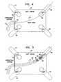
- FIG. 4schematically illustrates certain aspects of a preferred disclosed method of electrical pulmonary vein isolation.
- the description of Fig. 4should be read in conjunction with Fig. 3 .
- Fig. 4represents the status at the completion of step 50 ( Fig. 3 ).
- a cutaway view of a left atrial chamber 52includes a right superior pulmonary vein 54 and a left superior pulmonary vein 56, whose ostium 58 is indicated.
- the view of Fig. 4also includes a right inferior pulmonary vein 60, and a left inferior pulmonary vein 62.
- a conventional guiding sheath 64has a distal end 66, which has been positioned, on the left atrial side of an interatrial septum 68.
- a conventional guidewire 70extends through the lumen of the guiding sheath 64, into the lumen of the left superior pulmonary vein 56. It will be understood that while the guidewire 70 is shown in relation to the left superior pulmonary vein 56, the technique is equally applicable to the other pulmonary veins.
- the guiding sheathis withdrawn, and an ablation catheter is slidably tracked over the guidewire, using the guidewire lumen of the catheter.
- the catheteris advanced into the left atrium. While maneuvering the catheter in the heart, its position is preferably monitored by the location and mapping system disclosed in the above-noted U.S. Patent No. 5,840,025 , or alternatively by conventional imaging modalities.
- the anchoring balloon of the catheteris deflated during the positioning maneuver.
- the tip of the catheteris located at the ostium of a pulmonary vein, such that a first segment of the catheter's anchoring balloon, which is substantially the balloon's proximal third, is disposed in the left atrium, and a second segment of the anchoring balloon, composed of its remaining distal portion, lies within the lumen of the pulmonary vein.
- Fig. 5schematically illustrates certain preferred aspects of the disclosed method of electrical pulmonary vein isolation.
- the description of Fig. 5should be read in conjunction with Figs. 3 and 4.
- Fig. 5represents the status at the completion of step 72 ( Fig. 3 ).
- Structures in Fig. 5 that are identical to corresponding structures in Fig. 4have been given like reference numerals.
- the shaft of the catheter 10extends through the interatrial septum 68.
- the anchoring balloon 22 and the coil 34lie across the ostium 58 of the left superior pulmonary vein 56, and the principal axis of the coil 34 is substantially coaxial with the left superior pulmonary vein 56.
- the anchoring balloon 22is deflated, and the coil 34 is radially collapsed about the exterior wall of the anchoring balloon 22.
- the diameter of the collapsed coil 34is smaller than the diameter of the left superior pulmonary vein 56, such that the coil 34 is movable within the lumen.
- the coil 34is caused to expand radially, and circumferentially engage a portion of the inner lining of the pulmonary vein in which the target tissue is located. This is preferably accomplished by inflating the anchoring balloon, which urges the coil radially outward toward the inner wall of the pulmonary vein.
- the shape memory of the coil alloycan be exploited to cause the coil to expand by resistively heating the coil.
- the radially expanded coilengages the pulmonary vein in a continuous line that runs circumferentially about the pulmonary vein proximate its ostium, and the coil is seated in position and acts as a stent for the pulmonary vein. Perfusion of the area through one of the catheter ports may be employed during step 74 to minimize stasis of blood in the region.
- step 76once the position of the coil is confirmed, the radiofrequency generator is energized, and radiofrequency energy is conducted from the coil to the target tissue.
- FIG. 6schematically illustrates certain preferred aspects of the disclosed method of electrical pulmonary vein isolation.
- the description of Fig. 6should be read in conjunction with Figs. 3 and 5 , in which like reference numbers denote the same element throughout.
- Fig. 6represents the status at step 76 ( Fig. 3 ).
- the anchoring balloon 22is inflated, and the coil 34 is radially expanded and now functions as a stent for the left superior pulmonary vein 56.
- Two contact points 78 of the coil 34 and the wall of the left superior pulmonary vein 56are illustrated, it being understood that the contact actually occurs in a continuous circumferential line.
- the pitch-to-radius ratio of the coil 34is selected such that a circumferential ablation lesion produced in the target tissue bridges the distance between two adjacent loops, for example, loops 80, 82, thus forming a continuous circumferential band, having an obliquity in its orientation that conforms to the helix angle of the coil 34.
- the transfer of radiofrequency energy from the emitter to the pulmonary vein in step 76occurs in a single, relatively short application.
- the radiofrequency generator 42( Fig. 2 ) should produce a current of 100-300 mA in order to appropriately heat a coil to about 50 degrees C, the coil of being constructed of 0.1 mm shape memory alloy wire, and having an outer diameter of 3 cm.
- the energy applicationis controlled in response to continuous electrophysiological monitoring, an end point being reached when conduction block is confirmed across the line of ablation.
- step 84the anchoring balloon is deflated and the coil radially contracted.
- contraction of the coilis accomplished by resistive heating, exploiting the shape memory of the coil.
- the tip of the catheteris withdrawn into the left atrial chamber.
- the guidewireis also withdrawn from the pulmonary vein.
- step 86a test is made to determine if more pulmonary veins remain to be electrically isolated. If the determination is affirmative, then control proceeds to step 88, where the next pulmonary vein is selected. Control then returns to step 50.
- controlproceeds to final step 90.
- the anchoring balloonis deflated, and the entire apparatus withdrawn from the patient.
- the coilis separated from the anchoring balloon and left in place as a stent. The procedure thereupon terminates in either case.
- FIG. 7is a schematic view of a coil that is constructed and operative in accordance with an embodiment of the invention.
- a coil 92comprises a winding of wire, formed of a shape memory alloy.
- the loopsare folded into a plurality of zigzag folds or bends 94, which allow the coil 92 to axially expand when heated, using its shape memory properties in order to attain a desired length.
- the coilcan also be configured to radially expand, and can be left in situ as a stent if desired following the ablation.
- the loops of the coil 92are grouped in multiple segments, of which a segment 96 and a segment 98 are referenced. For clarity of illustration the segments 96, 98 are shown as being spaced apart. However, in practice they generally are not.
- the coil 92is placed on a catheter and introduced as disclosed hereinabove. It is then heated to accomplish shape adjustment.
- One or more ferrite cores 100receive radiofrequency energy from an external source (not shown).
- the radiofrequency transmitteris adjusted such that resultant electromagnetic fields have sufficient flux to heat the coil 92, and in embodiments having a plurality of ferrite cores, to differentially heat the segments 96, 98.
- An external loop antennawith a radius of 25-30 cm, having 10-20 windings, is powered by a radiofrequency power amplifier carrying 200-250 watts in order to provide enough energy to heat the coil 92.
- FIG. 8is a schematic view of a coil having a shape memory that is constructed and operative in accordance with an alternate embodiment of the invention, shown following an application of heat.
- a coil 102comprises a segment 104 and a segment 106.
- Three electrical leadsare provided within the interior of the coil 102, which are connected to a power source (not shown).
- a common lead 108is connected to the segment 104 at a junction 110.
- the lead 108is connected to the segment 106 at a junction 112.
- a second lead 114is connected to the segment 104 at a junction 116, and a third lead 118 is connected to the segment 106 at a junction 120.
- the segment 106When compared to the segment 104, the segment 106 is expanded longitudinally, such that its individual loops are more spaced apart from one another than the loops of the segment 104.
- the diameter of the segment 106is larger than the diameter of the segment 104. This is accomplished by passing more current through the segment 106 than through the segment 104, in order to achieve differential heating.
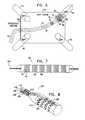
- FIG. 9is a schematic view of a coil having a shape memory that is constructed and operative in accordance with an alternate embodiment of the invention. It is possible to achieve differential segmental shape transformation by differentially heating of segments of a coil inductively.
- a coil 122is constructed of a shape memory alloy in the same manner as the coil 92 ( Fig. 7 ).
- a second coil 124made from a conventional electrical conductor, is mounted inside the coil 122 and is connected to a power source (not shown). Passing alternating current through the coil 124 inductively heats the coil 122.
- the power source(not shown) can produce different current flows through different segments of the coil 124 as described above.
- the coil 124is preferable mounted in the wall of the anchoring balloon 22 ( Fig. 1 ). It is preferable that the coil 122 and the coil 124 be about the same size in order to match the electrical loads carried by each of them.
- FIG. 10is a schematic view of a coil 123 having a shape memory that is constructed and operative in accordance with an alternate embodiment of the invention.
- the embodiment shown in Fig. 10is similar to that of Fig. 9 , and like elements are given like reference numerals.
- a coil 125is similar to the coil 124 ( Fig. 9 ). However, all segments of the coil 125 are now powered by a common electrical current from a power source (not shown).
- Conduits 132, 134each carry a stream of fluid, such as saline, which acts as a coolant. Control valves 136 regulate the flow through the conduits 132, 134.
- the salineflows out of the conduits 132, 134 through a plurality of openings 140 that are disposed opposite segments 96, 98 of the coil 123.
- the volume of saline effluentis locally controlled by the control valves 136, in order to achieve differential cooling of the segments 96, 98 of the coil 123. This results in regional differences in the shape transformation.
- a desired shape of the coil 123can be attained by appropriately adjusting the control valves 136. It is preferable that the coil 123 and the coil 125 be about the same size in order to match the electrical loads carried by each of them.
- Fig. 11is a schematic view of a coil having a shape memory that is constructed and operative in accordance with an alternate embodiment of the invention.
- the embodiment shown in Fig. 11is similar to that of Fig. 7 , and like elements are given like reference numerals.
- the coil 92is now provided with an ASIC circuit 144 that includes miniature sensors 146, 148 for measuring temperature and local circuit impedance. The information obtained from the sensors 146, 148 is processed using known digital processing techniques.
- the coil 92acts as an antenna, schematically referenced as antenna 150, for transmitting a signal from the ASIC circuit 144 to a control processor 152.
Landscapes
- Health & Medical Sciences (AREA)
- Life Sciences & Earth Sciences (AREA)
- Engineering & Computer Science (AREA)
- Surgery (AREA)
- General Health & Medical Sciences (AREA)
- Biomedical Technology (AREA)
- Heart & Thoracic Surgery (AREA)
- Animal Behavior & Ethology (AREA)
- Public Health (AREA)
- Veterinary Medicine (AREA)
- Nuclear Medicine, Radiotherapy & Molecular Imaging (AREA)
- Otolaryngology (AREA)
- Plasma & Fusion (AREA)
- Physics & Mathematics (AREA)
- Medical Informatics (AREA)
- Molecular Biology (AREA)
- Cardiology (AREA)
- Biophysics (AREA)
- Pulmonology (AREA)
- Anesthesiology (AREA)
- Hematology (AREA)
- Surgical Instruments (AREA)
- Media Introduction/Drainage Providing Device (AREA)
- Medicines Containing Material From Animals Or Micro-Organisms (AREA)
- Respiratory Apparatuses And Protective Means (AREA)
- Electrotherapy Devices (AREA)
- Pharmaceuticals Containing Other Organic And Inorganic Compounds (AREA)
- Orthopedics, Nursing, And Contraception (AREA)
- External Artificial Organs (AREA)
Abstract
Description
- This invention relates to apparatus for the medical treatment of disease of the heart. More particularly, this invention relates to apparatus for treating cardiac arrhythmias by ablating in a vicinity of pulmonary venous tissue.
- Tissue ablation from the inner walls of hollow viscera of the body generally, and the vascular system in particular, has been found to be useful in the treatment of various medical conditions. Technological developments in intravascular catheters, manipulative instruments adapted to intravascular catheters, and catheter localization techniques have especially benefited the field of cardiology. Percutaneous transcatheter ablation has been used successfully in the treatment of conduction defects and arrhythmias of various types. Today, atrial tachyarrhythmias are a common application for ablative therapy.
- Various ablative modalities have been employed in the past, such as ablation by direct heating. Energy can be conducted to the target tissue using various modalities, such as ultrasound, laser, resistive heating, and radiofrequency energy.
- One ablative approach is the so-called "maze" technique. In general, the maze procedure attempts to block abnormal conduction patterns in the left atrium by establishing a maze-like pattern of linear lesions in the left atrial wall.
- Atrial arrhythmias are known to be associated with abnormal electrical activity of tissue foci in the vicinity of the pulmonary veins, especially the superior pulmonary veins. Various ablative treatments of such foci have been attempted. For example, the production of linear atrial lesions by radiofrequency ablation, in combination with ablation of suspected arrhythmogenic foci has been performed using transcatheter techniques.
- More recently, circumferential lesions at or near the ostia of the pulmonary veins have been created to treat atrial arrhythmias.
U.S. Patent Nos. 6,012,457 and6,024,740 , both to Lesh, disclose a radially expandable ablation device, which includes a radiofrequency electrode. Using this device, it is proposed to deliver radiofrequency energy to the pulmonary veins in order to establish a circumferential conduction block, thereby electrically isolating the pulmonary veins from the left atrium. - Radiofrequency ablation using multiple contiguous circumferential points, guided by electro-anatomical mapping is proposed in the document,Circumferential Radiofrequency Ablation of Pulmonary Vein Ostia: A New Anatomic Approach for Curing Atrial Fibrillation, Pappone C, Rosanio S, Oreto G, Tocchi M, Gugliotta F, Vicedomini G, Salvati A, Dicandia C, Mazzone P, Santinelli V, Gulletta S, Chierchia S, Circulation 102:2619-2628 (2000). It is emphasized that particular care must be exercised to ensure that the ablation sites are indeed contiguous; otherwise irregular electrical activity in the pulmonary vein may continue to contribute to atrial arrhythmia.
- It has also been proposed to produce circumferential ablative lesions using ultrasound delivered through a balloon. This technique is described, for example, in the document,First Human Experience With Pulmonary Vein Isolation Using a Through-the-Balloon Circumferential Ultrasound Ablation System for Recurrent Atrial Fibrillation, Natale A, Pisano E, Shewchik J, Bash D, Fanelli R, MD; Potenza D; Santarelli P; Schweikert R; White R; Saliba W; Kanagaratnam L; Tchou P; Lesh M, Circulation 102:1879-1882 (2000).
- A known drawback in the use of radio frequency energy for cardiac tissue ablation is the difficulty in controlling the local heating of tissue. There are tradeoffs between the clinical desire to create a sufficiently large lesion to effectively ablate an abnormal tissue focus, or block an aberrant conduction pattern, and the undesirable effects of excessive local heating. If the radiofrequency device creates too small a lesion, then the medical procedure could be less effective, or could require too much time. On the other hand, if tissues are heated excessively then there could be local charring effects due to overheating. Such overheated areas can develop high impedance, and may form a functional barrier to the passage of heat. The use of slower heating provides better control of the ablation, but unduly prolongs the procedure.
- In consideration of these, and other factors, it is appropriate, in designing a practical radiofrequency electrode, to consider the amplitude of the radiofrequency signal, the amount of time required for the energy application, the size of the electrode, and the contact area, as well as ease of positioning, withdrawal, and repositioning of the device so as to be able to conveniently produce multiple lesions during the same medical procedure.
- Previous approaches to controlling local heating include the inclusion of thermocouples within the electrode and feedback control, modulation of the radiofrequency signal, local cooling of the catheter tip, and fluid assisted techniques, for example perfusion of the target tissue during the energy application, using chilled fluids. Typical of the last approach is Mulier,et al.
U.S. Patent No. 5,807,395 . - Known solutions to electrical pulmonary vein isolation typically require four to seven radiofrequency applications for completion of the isolation of each pulmonary vein. Other techniques utilize a coil within an expandable balloon. Radiofrequency or ultrasound energy from the coil is passed through the balloon together with a conductive fluid, into surrounding tissue.
- Publications which describe various medical techniques of interest include:
- 1.Scheinman MM, Morady F. Nonpharmacological Approaches to Atrial Fibrillation. Circulation 2001;103:2120-2125.
- 2.Wang PJ, Homoud MK, Link MS, Estes III NA. Alternate energy sources for catheter ablation. Curr Cardiol Rep 1999 Jul;1(2):165-171.
- 3.Fried NM, Lardo AC, Berger RD, Calkins H, Halperin HR. Linear lesions in myocardium created by Nd:YAG laser using diffusing optical fibers: in vitro and in vivo results. Lasers Surg Med 2000;27(4):295-304.
- 4.Eigler NL, Khorsandi MJ, Forrester JS, Fishbein MC, Litvack F. Implantation and recovery of temporary metallic stents in canine coronary arteries. J Am Coll Cardiol 1993; 22(4):1207-1213.
- 5.Synthetic Biodegradable Polymers as Medical Devices; by John C. Middleton and Arthur J. Tipton. 1998.
- 6.Keane D, Ruskin J, Linear atrial ablation with a diode laser and fiber optic catheter. Circulation 1999; 100:e59-e60.
- 7.Ware D, et al., Slow intramural heating with diffused laser light: A unique method for deep myocardial coagulation. Circulation; March 30, 1999; pp. 1630-1636.
- Other medical technologies of interest are described in
U.S. Patent Nos. 5,891,134 to Goble et al. ,5,433,708 to Nichols et al. ,4,979,948 to Geddes et al. ,6,004,269 to Crowley et al. ,5,366,490 to Edwards et al. ,5,971,983 ,6,164,283 , and6,245,064 to Lesh ,6,190,382 to Ormsby et al. ,6,251,109 and6,090,084 to Hassett et al. ,5,938,600 to Swartz et al. ,6,064,902 to Haissaguerre et al. , and6,117,101 to Diederich et al . WO 01/19269 US 2002/0004644 discloses a system which includes a helical stent constructed of a shape memory alloy and means for varying the temperature of the stent in order to alter a configuration thereof to radially expand the coil.- It is therefore a primary object of some aspects of the present invention to provide improved apparatus for electrically isolating the pulmonary vein by accomplishing a circumferential conduction block surrounding the pulmonary vein ostium in a single ablation application.
- It is another object of some aspects of the present invention to reduce the time required to perform electrical isolation of the pulmonary veins.
- These and other objects of the present invention are attained by the system for ablating tissue defined in the accompanying claim 1. In a further embodiment of the invention, the helical coil is constructed of a biodegradable material, and is left in place following the ablative procedure.
- In one aspect of the invention, the means for providing the coil is adapted to form zigzag folds in a plurality of windings thereof. According to another aspect, a proximal segment of the coil is more radially expandable than a distal segment thereof.
- According to another aspect of the invention, the means for radially expanding the coil is adapted to cause tapering of the coil.
- In a further aspect of the invention, the means for circumferentially engaging the coil is adapted to cause axial expansion of the coil.
- In yet another aspect of the invention, the means for differentially heating is adapted to pass different amounts of current through different ones of the segments of the coil.
- In yet another aspect of the invention, the means for differentially heating is an inductive heating means.
- In still another aspect of the invention, the means for differential heating is adapted to subject the coil to a single electromagnetic influence for heating thereof, and conduct a coolant to selected ones of the segments of the coil.
- According to yet another aspect of the invention, the coil is constructed of a biodegradable material.
- In still another aspect of the invention, the means for conducting radiofrequency energy is adapted to perform in a single continuous application.
- The associated method, which is described herein but not claimed, is applicable to hollow viscera other than the heart and the pulmonary veins.
- For a better understanding of these and other objects of the present invention, reference is made to the detailed description of the invention, by way of example, which is to be read in conjunction with the following drawings, wherein:
Figs. 1A and 1B , collectively referred to herein asFig. 1 , illustrate a therapeutic catheter that is constructed and operative in accordance with a preferred embodiment of the invention;Fig. 2 is an enlarged schematic illustration of the distal end of the catheter shown inFig. 1 with an inflation balloon expanded, and a radiofrequency ablation element in place;Fig. 3 is a flow chart of a method for electrically isolating the pulmonary vein, which is operative in accordance with a preferred embodiment of the invention;Fig. 4 schematically illustrates certain aspects of a method of intracardiac catheter access during a first phase of the method shown inFig. 3 ;Fig. 5 schematically illustrates certain aspects of a method of intracardiac catheter access during a second phase of the method shown inFig. 3 ;Fig. 6 schematically illustrates certain aspects of a method of intracardiac catheter access during a third phase of the method shown inFig. 3 ;Fig. 7 is a schematic view of a coil that is constructed and operable in accordance with an alternate embodiment of the invention;Fig. 8 is a schematic view of a coil having a shape memory that is constructed and operative in accordance with an alternate embodiment of the invention shown following an application of heat;Fig. 9 is a schematic view of a coil having a shape memory that is constructed and operative in accordance with an alternate embodiment of the invention;Fig. 10 is a schematic view of a coil having a shape memory that is constructed and operative in accordance with an alternate embodiment of the invention; andFig. 11 is a schematic view of a coil having a shape memory that is constructed and operative in accordance with an alternate embodiment of the invention, which includes an ASIC circuit and has transmitting capability.- In the following description, numerous specific details are set forth in order to provide a thorough understanding of the present invention. It will be apparent to one skilled in the art, however, that the present invention may be practiced without these specific details. In other instances, well known circuits, control logic, and other apparatus have not been shown in detail in order not to unnecessarily obscure the present invention. The embodiments are disclosed with reference to a particular anatomic site. However, the invention can be practiced in many anatomic sites where it is desirable to ablate tissue in the walls of hollow viscera.
- Turning now to the drawings, reference is made to
Figs. 1A and 1B , which illustrate a medical device that is constructed and operative in accordance with a preferred embodiment of the invention. Anintravascular catheter 10 has aproximal end 12 and adistal end 14. Thedistal end 14 is provided with at least oneseal 16, and optionally asecond seal 18. Theseals catheter 10 has one or more lumens, which conduct fluid for inflating and deflating theseals port 20, and is useful for injection of fluids and withdrawal of blood as may be required during use. Other lumens are provided for passage of guidewires and instruments therethrough. Aninflatable anchoring balloon 22, shown in a deflated condition, is located distal to theseals catheter 10 also has acoaxial guidewire lumen 24. - Preferably the active sites to be ablated are identified using the location and mapping system disclosed in commonly assigned
U.S. Patent No. 5,840,025 andU.S. Patent No. 5,391,199 . For the embodiment ofU.S. Patent No. 5,840,025 , certain components of the location and mapping system are incorporated into thedistal end 14 of thecatheter 10, namely amapping electrode 26 and a transmittingantenna 28, which can be a dipole antenna. Themapping electrode 26 detects local electrical activity of the heart, and theantenna 28 transmits signals to a plurality of receiving antennae (not shown) which are placed on the body surface of a patient during use. Thedistal end 14 can be radio-opaque, in order to facilitate its localization by conventional radiographic techniques, alternatively or in addition to the system disclosed in the above-notedU.S. Patent No. 5,840,025 . - For the embodiment disclosed in
U.S. Patent No. 5,391,199 certain components of the location and mapping system are incorporated into thedistal end 14 of thecatheter 10, namely themapping electrode 26 and alocation sensor 28, which is a position and orientation sensor . Themapping electrode 26 detects local electrical activity of the heart, and thelocation sensor 28 receives electromagnetic field signals from a plurality of electromagnetic field generators (not shown) which are placed exterior of the patient such as on the body surface of a patient during use and transmit electromagnetic fields to define a frame of reference in order to track the position and orientation of the catheterdistal end 14. Thus, based on the electromagnetic fields received at thelocation sensor 28, thelocation sensor 28 transmits a location signal to the signal processor/control system (not shown) by providing at least 5 dimensions of position and orientation information (X, Y, Z, Pitch and Yaw) in the form of coordinate information and, in some embodiments provide 6 dimensions of position and orientation information (X, Y, Z, Pitch, Yaw and Roll) in the form of coordinate information. Thedistal end 14 can be radio-opaque, in order to facilitate its localization by conventional radiographic techniques, alternatively or in addition to the system disclosed in the above-notedU.S. Patent No. 5,391,199 . - In embodiments in which the system disclosed in the above-noted
U.S. Patent Nos. 5,840,025 and5,391,199 is not used, themapping electrode 26 performs conventional monitoring of local electrical activity, and theantenna 28 can be omitted. - Reference is now made to
Fig. 2 , which is a partially schematic enlarged view of thedistal end 14 of thecatheter 10 shown inFig. 1 . This embodiment falls outside the scope of the claims. The anchoringballoon 22 is inflated, and preferably has a large-radius proximal lobe orsegment 30, and a small-radius distal lobe orsegment 32. The bilobate configuration of the anchoringballoon 22 aids in securely positioning it within the ostium of a pulmonary vein. Alternatively the anchoringballoon 22 can be pyriform, ellipsoidal, or otherwise constructed, so long as its proximal portion is more radially expanded than its distal portion e.g. the proximal portion has a larger expanded diameter than the expanded diameter of the distal portion. The anchoringballoon 22 is constructed of conventional materials. Securely wrapped about the external surface of the anchoringballoon 22 is a distally taperinghelical coil 34 or stent, preferably constructed of nickel titanium (nitinol) or other shape memory alloy. This material is suitable for use within the body and can easily be heated up by applying voltage. It can be readily formed into a desired shape by well-known techniques. The axis of thecoil 34 and the axis of the anchoringballoon 22 are both generally aligned, as indicated by aline 36. The pitch of thecoil 34 is represented by the linear distance between the same points on adjacent loops, for example the distance between apoint 38 and apoint 40 on theline 36. The pitch of different segments of thecoil 34 may vary. - The
coil 34 is connected to asuitable radiofrequency generator 42 by alead 44. Thecoil 34 is preferably formed of 0.1 mm. gauge wire and has about 4 - 5 turns, its preferred length is about 2 - 3 cm. The helix angle is not critical. In any case, a certain amount of deformation occurs during placement. The length of the expanded coil varies with the application. - The helical shape of the
coil 34 has important advantages, compared with other known elements that have been used in the past for circumferential pulmonary vein isolation. In some applications, it may be desirable to allow thecoil 34 to remainin situ following an ablative procedure, and because of its helical shape, thecoil 34 is adaptable for use as a stent. Construction is simple, and the pitch and taper of the spiral can be readily adjusted for individual variations in the anatomy of the various pulmonary veins, either by selecting a coil from a series of coils having standard sizes, or throughad hoc modification by the operator. It is believed to be less expensive to reliably construct a simple spiral than the more complex structures that are disclosed, for example, in the above-notedU.S. Patent No. 6,012,457 . The helical shape takes full advantage of the shape memory properties of the alloy, which promotes ease of use, radial expansion and contraction, and withdrawal following completion of the ablative lesion. - More generally, use of the coil as described facilitates the creation of a complete line of block surrounding the pulmonary vein ostium in a single ablation application. By contrast, some currently available techniques require multiple RF ablations, e.g., four to seven ablations , for completion of the isolation of each pulmonary vein. Other techniques utilize a coil within an expandable balloon, whereby radiofrequency energy from the coil is passed to a conductive fluid in the balloon, then through the balloon, and only at that point into surrounding tissue. Advantageously, procedures performed using the coil provided by this embodiment of the present invention are believed to be simpler, quicker, and more efficient than those which use the methods provided by the prior art.
- Preferably the
coil 34 is securely attached to the anchoringballoon 22 or thedistal end 14 of thecatheter 10, and is removed from the pulmonary vein ostium when thecatheter 10 is withdrawn at the completion of the procedure. - In some embodiments, the
coil 34 is made of a biodegradable material, for example polymer polylactide and trimethylene carbonate polymers. In these embodiments, thecoil 34 is expanded sufficiently prior to or during the ablation to become securely circumferentially attached to the wall of the pulmonary vein. It is detachable from the anchoringballoon 22 or thedistal end 14 of thecatheter 10. In these embodiments thecoil 34 remains firmly engaged circumferentially with the inner lining of the pulmonary vein as a result of its elasticity and shape memory. Thecoil 34 is allowed to remainin situ following the ablation procedure, and it is eventually resorbed. In such embodiments, the continued stenting of the pulmonary vein by the coil may reduce the risk of contracture and stenosis of the pulmonary veins. Additionally, in some embodiments, the coil 34 (stent)is coated with a drug for preventing stenosis of the vessel. The coating on the coil 34 may be used to deliver therapeutic and pharmaceutic agents including: antiproliferative/antimitotic agents including natural products such as vinca alkaloids (i.e. vinblastine, vincristine, and vinorelbine), paclitaxel, epidipodophyllotoxins (i.e. etoposide, teniposide), antibiotics (dactinomycin (actinomycin D) daunorubicin, doxorubicin and idarubicin), anthracyclines, mitoxantrone, bleomycins, plicamycin (mithramycin) and mitomycin, enzymes (L-asparaginase which systemically metabolizes L-asparagine and deprives cells which do not have the capacity to synthesize their own asparagine); antiplatelet agents such as G(GP)IIbIIIa inhibitors and vitronectin receptor antagonists; antiproliferative/antimitotic alkylating agents such as nitrogen mustards (mechlorethamine, cyclophosphamide and analogs, melphalan, chlorambucil), ethylenimines and methylmelamines (hexamethylmelamine and thiotepa), alkyl sulfonates-busulfan, nirtosoureas (carmustine (BCNU) and analogs, streptozocin), trazenes - dacarbazinine (DTIC); antiproliferative/antimitotic antimetabolites such as folic acid analogs (methotrexate), pyrimidine analogs (fluorouracil, floxuridine, and cytarabine), purine analogs and related inhibitors (mercaptopurine, thioguanine, pentostatin and 2-chlorodeoxyadenosine {cladribine}); platinum coordination complexes (cisplatin, carboplatin), procarbazine, hydroxyurea, mitotane, aminoglutethimide; hormones (i.e. estrogen); anticoagulants (heparin, synthetic heparin salts and other inhibitors of thrombin); fibrinolytic agents (such as tissue plasminogen activator, streptokinase and urokinase), aspirin, dipyridamole, ticlopidine, clopidogrel, abciximab; antimigratory; antisecretory (breveldin); antiinflammatory: such as adrenocortical steroids (cortisol, cortisone, fludrocortisone, prednisone, prednisolone, 6α-methylprednisolone, triamcinolone, betamethasone, and dexamethasone), non-steroidal agents (salicylic acid derivatives i.e. aspirin; para-aminophenol derivatives i.e. acetominophen; indole and indene acetic acids (indomethacin, sulindac, and etodalac), heteroaryl acetic acids (tolmetin, diclofenac, and ketorolac), arylpropionic acids (ibuprofen and derivatives), anthranilic acids (mefenamic acid, and meclofenamic acid), enolic acids (piroxicam, tenoxicam, phenylbutazone, and oxyphenthatrazone), nabumetone, gold compounds (auranofin, aurothioglucose, gold sodium thiomalate); immunosuppressives: (cyclosporine, tacrolimus (FK-506), sirolimus (rapamycin), azathioprine, mycophenolate mofetil); angiogenic agents: vascular endothelial growth factor (VEGF), fibroblast growth factor (FGF); angiotensin receptor blocker; nitric oxide donors; anti-sense oligionucleotides and combinations thereof; cell cycle inhibitors, mTOR inhibitors, and growth factor signal transduction kinase inhibitors. - Reference is now made to
Fig. 3 , which is a flow chart of a method for electrically isolating pulmonary veins, which is operative in accordance with a preferred embodiment of the invention. The description ofFig. 3 should be read in conjunction withFigs. 1 and 2 . - In
initial step 46 routine preparation of a subject (not shown) and equipment are accomplished. This includes attachment of various monitoring and grounding leads, as may be required for electrophysiological monitoring of the procedure, and for the operation of the above-noted location and mapping system. - Next, at
step 48, a series of events begins, ultimately leading to the positioning of thecatheter 10 and thecoil 34 at the ostium of a pulmonary vein.Step 48 is conventional. In a preferred approach, the venous system is accessed using the well-known Seldinger technique, in which an introducer sheath is positioned in a peripheral vein, typically a femoral vein. A guiding sheath is introduced through the introducer sheath, and is advanced via the inferior vena cava into the right atrium. Then, using a Brockenbrough needle, the fossa ovalis of the interatrial septum is punctured, and the puncture dilated if necessary. The Brockenbrough needle is withdrawn, and the guiding sheath placed in the left atrium. Alternatively, the ablation catheter is energized as it contacts the interatrial septum, usually at the fossa ovalis. Ablation of septal tissue eases the passage of the catheter through the septum, reduces the amount of hardware used, and shortens the procedure, as it is not necessary to pass a dilator through the fossa ovalis. It is also possible to access the left atrium via the superior vena cava, or to use a retrograde intra-arterial technique. - Next, in step 50 a guidewire is advanced through the guiding sheath, through the left atrial chamber, into a pulmonary vein.
- The order in which the specific pulmonary veins are visited and treated is arbitrary, but it is preferable to concentrate first on the two superior pulmonary veins, in which the muscular sleeves are more prominent than in the inferior pulmonary veins. Thereafter the inferior pulmonary veins may be isolated. Typically, an ablation procedure involves the isolation of all four pulmonary veins.
- Reference is now made to
Fig. 4 , which schematically illustrates certain aspects of a preferred disclosed method of electrical pulmonary vein isolation. The description ofFig. 4 should be read in conjunction withFig. 3 .Fig. 4 represents the status at the completion of step 50 (Fig. 3 ). A cutaway view of a leftatrial chamber 52 includes a right superiorpulmonary vein 54 and a left superiorpulmonary vein 56, whoseostium 58 is indicated. The view ofFig. 4 also includes a right inferiorpulmonary vein 60, and a left inferiorpulmonary vein 62. Aconventional guiding sheath 64 has adistal end 66, which has been positioned, on the left atrial side of aninteratrial septum 68. Aconventional guidewire 70 extends through the lumen of the guidingsheath 64, into the lumen of the left superiorpulmonary vein 56. It will be understood that while theguidewire 70 is shown in relation to the left superiorpulmonary vein 56, the technique is equally applicable to the other pulmonary veins. - Referring again to
Fig. 3 , atstep 72, the guiding sheath is withdrawn, and an ablation catheter is slidably tracked over the guidewire, using the guidewire lumen of the catheter. The catheter is advanced into the left atrium. While maneuvering the catheter in the heart, its position is preferably monitored by the location and mapping system disclosed in the above-notedU.S. Patent No. 5,840,025 , or alternatively by conventional imaging modalities. The anchoring balloon of the catheter is deflated during the positioning maneuver. The tip of the catheter is located at the ostium of a pulmonary vein, such that a first segment of the catheter's anchoring balloon, which is substantially the balloon's proximal third, is disposed in the left atrium, and a second segment of the anchoring balloon, composed of its remaining distal portion, lies within the lumen of the pulmonary vein. - Reference is now made to
Fig. 5 , which schematically illustrates certain preferred aspects of the disclosed method of electrical pulmonary vein isolation. The description ofFig. 5 should be read in conjunction withFigs. 3 and4. Fig. 5 represents the status at the completion of step 72 (Fig. 3 ). Structures inFig. 5 that are identical to corresponding structures inFig. 4 have been given like reference numerals. The shaft of thecatheter 10 extends through theinteratrial septum 68. The anchoringballoon 22 and thecoil 34 lie across theostium 58 of the left superiorpulmonary vein 56, and the principal axis of thecoil 34 is substantially coaxial with the left superiorpulmonary vein 56. During placement, the anchoringballoon 22 is deflated, and thecoil 34 is radially collapsed about the exterior wall of the anchoringballoon 22. The diameter of the collapsedcoil 34 is smaller than the diameter of the left superiorpulmonary vein 56, such that thecoil 34 is movable within the lumen. - Referring again to
Fig. 3 , atstep 74, thecoil 34 is caused to expand radially, and circumferentially engage a portion of the inner lining of the pulmonary vein in which the target tissue is located. This is preferably accomplished by inflating the anchoring balloon, which urges the coil radially outward toward the inner wall of the pulmonary vein. In some embodiments, the shape memory of the coil alloy can be exploited to cause the coil to expand by resistively heating the coil. The radially expanded coil engages the pulmonary vein in a continuous line that runs circumferentially about the pulmonary vein proximate its ostium, and the coil is seated in position and acts as a stent for the pulmonary vein. Perfusion of the area through one of the catheter ports may be employed duringstep 74 to minimize stasis of blood in the region. - In
step 76, once the position of the coil is confirmed, the radiofrequency generator is energized, and radiofrequency energy is conducted from the coil to the target tissue. - Reference is now made to
Fig. 6 , which schematically illustrates certain preferred aspects of the disclosed method of electrical pulmonary vein isolation. The description ofFig. 6 should be read in conjunction withFigs. 3 and5 , in which like reference numbers denote the same element throughout.Fig. 6 represents the status at step 76 (Fig. 3 ). The anchoringballoon 22 is inflated, and thecoil 34 is radially expanded and now functions as a stent for the left superiorpulmonary vein 56. Two contact points 78 of thecoil 34 and the wall of the left superiorpulmonary vein 56 are illustrated, it being understood that the contact actually occurs in a continuous circumferential line. The pitch-to-radius ratio of thecoil 34 is selected such that a circumferential ablation lesion produced in the target tissue bridges the distance between two adjacent loops, for example,loops coil 34. - Referring again to
Fig. 3 , the transfer of radiofrequency energy from the emitter to the pulmonary vein instep 76 occurs in a single, relatively short application. The radiofrequency generator 42 (Fig. 2 ) should produce a current of 100-300 mA in order to appropriately heat a coil to about 50 degrees C, the coil of being constructed of 0.1 mm shape memory alloy wire, and having an outer diameter of 3 cm. The energy application is controlled in response to continuous electrophysiological monitoring, an end point being reached when conduction block is confirmed across the line of ablation. - Upon completion of the ablation, in
step 84 the anchoring balloon is deflated and the coil radially contracted. In some embodiments, contraction of the coil is accomplished by resistive heating, exploiting the shape memory of the coil. The tip of the catheter is withdrawn into the left atrial chamber. The guidewire is also withdrawn from the pulmonary vein. - Next, at
decision step 86, a test is made to determine if more pulmonary veins remain to be electrically isolated. If the determination is affirmative, then control proceeds to step 88, where the next pulmonary vein is selected. Control then returns to step 50. - If the determination at
decision step 86 is negative, then control proceeds tofinal step 90. The anchoring balloon is deflated, and the entire apparatus withdrawn from the patient. In embodiments in which the coil is biodegradable, the coil is separated from the anchoring balloon and left in place as a stent. The procedure thereupon terminates in either case. - Reference is now made to
Fig. 7 , which is a schematic view of a coil that is constructed and operative in accordance with an embodiment of the invention. Acoil 92 comprises a winding of wire, formed of a shape memory alloy. The loops are folded into a plurality of zigzag folds or bends 94, which allow thecoil 92 to axially expand when heated, using its shape memory properties in order to attain a desired length. The coil can also be configured to radially expand, and can be leftin situ as a stent if desired following the ablation. - The loops of the
coil 92 are grouped in multiple segments, of which asegment 96 and asegment 98 are referenced. For clarity of illustration thesegments coil 92 is placed on a catheter and introduced as disclosed hereinabove. It is then heated to accomplish shape adjustment. One ormore ferrite cores 100 receive radiofrequency energy from an external source (not shown). The radiofrequency transmitter is adjusted such that resultant electromagnetic fields have sufficient flux to heat thecoil 92, and in embodiments having a plurality of ferrite cores, to differentially heat thesegments coil 92. - Reference is now made to
Fig. 8 , which is a schematic view of a coil having a shape memory that is constructed and operative in accordance with an alternate embodiment of the invention, shown following an application of heat. This embodiment is similar to the embodiment ofFig. 7 , with provision for powering individual segments of the coil. Acoil 102 comprises asegment 104 and asegment 106. Three electrical leads are provided within the interior of thecoil 102, which are connected to a power source (not shown). Acommon lead 108 is connected to thesegment 104 at ajunction 110. Thelead 108 is connected to thesegment 106 at ajunction 112. Asecond lead 114 is connected to thesegment 104 at ajunction 116, and athird lead 118 is connected to thesegment 106 at ajunction 120. When compared to thesegment 104, thesegment 106 is expanded longitudinally, such that its individual loops are more spaced apart from one another than the loops of thesegment 104. The diameter of thesegment 106 is larger than the diameter of thesegment 104. This is accomplished by passing more current through thesegment 106 than through thesegment 104, in order to achieve differential heating. - Reference is now made to
Fig. 9 , which is a schematic view of a coil having a shape memory that is constructed and operative in accordance with an alternate embodiment of the invention. It is possible to achieve differential segmental shape transformation by differentially heating of segments of a coil inductively. Acoil 122 is constructed of a shape memory alloy in the same manner as the coil 92 (Fig. 7 ). Asecond coil 124, made from a conventional electrical conductor, is mounted inside thecoil 122 and is connected to a power source (not shown). Passing alternating current through thecoil 124 inductively heats thecoil 122. Using segmentalelectrical leads electrical lead 130, the power source (not shown) can produce different current flows through different segments of thecoil 124 as described above. This results in correspondingly different inductive heat production in the overlying regions of thecoil 122. Thecoil 124 is preferable mounted in the wall of the anchoring balloon 22 (Fig. 1 ). It is preferable that thecoil 122 and thecoil 124 be about the same size in order to match the electrical loads carried by each of them. - Reference is now made to
Fig. 10 , which is a schematic view of acoil 123 having a shape memory that is constructed and operative in accordance with an alternate embodiment of the invention. The embodiment shown inFig. 10 is similar to that ofFig. 9 , and like elements are given like reference numerals. Acoil 125 is similar to the coil 124 (Fig. 9 ). However, all segments of thecoil 125 are now powered by a common electrical current from a power source (not shown).Conduits Control valves 136 regulate the flow through theconduits conduits openings 140 that are disposedopposite segments coil 123. The volume of saline effluent is locally controlled by thecontrol valves 136, in order to achieve differential cooling of thesegments coil 123. This results in regional differences in the shape transformation. A desired shape of thecoil 123 can be attained by appropriately adjusting thecontrol valves 136. It is preferable that thecoil 123 and thecoil 125 be about the same size in order to match the electrical loads carried by each of them. - Reference is now made to
Fig. 11 , which is a schematic view of a coil having a shape memory that is constructed and operative in accordance with an alternate embodiment of the invention. The embodiment shown inFig. 11 is similar to that ofFig. 7 , and like elements are given like reference numerals. Thecoil 92 is now provided with anASIC circuit 144 that includesminiature sensors sensors coil 92 acts as an antenna, schematically referenced asantenna 150, for transmitting a signal from theASIC circuit 144 to acontrol processor 152. - It will be appreciated by persons skilled in the art that the present invention is not limited to what has been particularly shown and described hereinabove.
Claims (10)
- A system for ablating tissue, comprising:means for providing a coil (34; 92; 102; 122; 123) that is constructed of a shape memory alloy;means (10) for introducing said coil into a hollow viscus (56);means (22; 100; 108, 114, 118; 124; 125) for circumferentially engaging said coil with an inner wall of said viscus to define a circumferential region of contact between said coil and said inner wall; andmeans (42) for conducting radiofrequency energy from said coil to said circumferential region of contact, while maintaining said circumferential region of contact, to ablate tissue therein,wherein said means for engaging (22; 100; 108, 114, 118; 124; 125) is adapted to circumferentially engage said coil (34; 92; 102; 122; 123) by radially expanding said coil,characterised by the system further comprising means (100; 108, 114, 118; 124; 125, 132, 134) for varying a temperature of said coil (92; 102; 122; 123) to alter a configuration thereof, the system being adapted such that, while said means (100; 108, 114, 118; 124; 125, 132, 134) for varying said temperature is operating, said coil (92; 102; 122; 123) radially expands responsive to a shape memory thereof, and the system further including means (100; 108, 114, 118; 124; 125) for differentially heating segments (30, 32; 96, 98; 104, 106) of said coil for expanding said coil (92; 102; 122; 123).
- The system according to claim 1, wherein said means for providing said coil (92; 102; 122; 123) is adapted to form zigzag folds (94) in a plurality of windings thereof.
- The system according to claim 1 or claim 2, wherein a proximal segment (30; 96; 104) of said coil (34; 92; 102; 122; 123) is more radially expandable than a distal segment (32; 98; 106) thereof.
- The system according to any of claims 1 to 3, wherein said means (22; 100; 108, 114, 118; 124; 125, 132, 134) for radially expanding said coil is adapted to cause tapering of said coil.
- The system according to any preceding claim , wherein said means (22; 100; 108, 114, 118; 124; 125) for circumferentially engaging said coil is adapted to cause axial expansion of said coil (34; 92; 102; 122; 123).
- The system according to any of claims 1 to 5, wherein said means (108, 114, 118; 124) for differentially heating is adapted to pass different amounts of current through different ones of said segments (96, 98; 104, 106) of said coil.
- The system according to any of claims 1 to 5, wherein said means (108, 114, 118; 124) for differentially heating is an inductive heating means.
- The system according to any of claims 1 to 5, wherein said means (125, 132, 134) for differentially heating is adapted to:subject said coil (123) to a single electromagnetic influence for heating thereof; andconduct a coolant to selected ones of said segments (96, 98) of said coil (123).
- The system according to any preceding claim, wherein said coil (34; 92; 102; 122; 123) is constructed of a biodegradable material.
- The system according to any preceding claim, wherein said means (42) for conducting radiofrequency energy is adapted to perform in a single continuous application.
Applications Claiming Priority (2)
| Application Number | Priority Date | Filing Date | Title |
|---|---|---|---|
| US62698 | 2002-01-31 | ||
| US10/062,698US6814733B2 (en) | 2002-01-31 | 2002-01-31 | Radio frequency pulmonary vein isolation |
Publications (2)
| Publication Number | Publication Date |
|---|---|
| EP1332724A1 EP1332724A1 (en) | 2003-08-06 |
| EP1332724B1true EP1332724B1 (en) | 2008-03-19 |
Family
ID=22044209
Family Applications (1)
| Application Number | Title | Priority Date | Filing Date |
|---|---|---|---|
| EP03250562AExpired - LifetimeEP1332724B1 (en) | 2002-01-31 | 2003-01-30 | Radio frequency pulmonary vein isolation |
Country Status (12)
| Country | Link |
|---|---|
| US (1) | US6814733B2 (en) |
| EP (1) | EP1332724B1 (en) |
| JP (1) | JP2003260063A (en) |
| KR (1) | KR20030066399A (en) |
| AT (1) | ATE389362T1 (en) |
| AU (1) | AU2002325454B2 (en) |
| CA (1) | CA2418504A1 (en) |
| DE (1) | DE60319759T2 (en) |
| DK (1) | DK1332724T3 (en) |
| ES (1) | ES2301758T3 (en) |
| IL (1) | IL153712A0 (en) |
| PT (1) | PT1332724E (en) |
Cited By (4)
| Publication number | Priority date | Publication date | Assignee | Title |
|---|---|---|---|---|
| US9289255B2 (en) | 2002-04-08 | 2016-03-22 | Medtronic Ardian Luxembourg S.A.R.L. | Methods and apparatus for renal neuromodulation |
| US9452017B2 (en) | 2012-05-11 | 2016-09-27 | Medtronic Ardian Luxembourg S.A.R.L. | Multi-electrode catheter assemblies for renal neuromodulation and associated systems and methods |
| US9554848B2 (en) | 1999-04-05 | 2017-01-31 | Medtronic, Inc. | Ablation catheters and associated systems and methods |
| US10188457B2 (en) | 2003-09-12 | 2019-01-29 | Vessix Vascular, Inc. | Selectable eccentric remodeling and/or ablation |
Families Citing this family (360)
| Publication number | Priority date | Publication date | Assignee | Title |
|---|---|---|---|---|
| US6716242B1 (en)* | 1999-10-13 | 2004-04-06 | Peter A. Altman | Pulmonary vein stent and method for use |
| US20140018880A1 (en) | 2002-04-08 | 2014-01-16 | Medtronic Ardian Luxembourg S.A.R.L. | Methods for monopolar renal neuromodulation |
| US7756583B2 (en) | 2002-04-08 | 2010-07-13 | Ardian, Inc. | Methods and apparatus for intravascularly-induced neuromodulation |
| US8150519B2 (en) | 2002-04-08 | 2012-04-03 | Ardian, Inc. | Methods and apparatus for bilateral renal neuromodulation |
| US8774922B2 (en) | 2002-04-08 | 2014-07-08 | Medtronic Ardian Luxembourg S.A.R.L. | Catheter apparatuses having expandable balloons for renal neuromodulation and associated systems and methods |
| US8774913B2 (en) | 2002-04-08 | 2014-07-08 | Medtronic Ardian Luxembourg S.A.R.L. | Methods and apparatus for intravasculary-induced neuromodulation |
| US7617005B2 (en)* | 2002-04-08 | 2009-11-10 | Ardian, Inc. | Methods and apparatus for thermally-induced renal neuromodulation |
| US8347891B2 (en) | 2002-04-08 | 2013-01-08 | Medtronic Ardian Luxembourg S.A.R.L. | Methods and apparatus for performing a non-continuous circumferential treatment of a body lumen |
| US20040049121A1 (en)* | 2002-09-06 | 2004-03-11 | Uri Yaron | Positioning system for neurological procedures in the brain |
| US6895282B2 (en)* | 2002-10-04 | 2005-05-17 | Boston Scientific Scimed, Inc. | Induction heating for the delivery of thermal therapy |
| US7270662B2 (en)* | 2004-01-21 | 2007-09-18 | Naheed Visram | Surgical perforation device with electrocardiogram (ECG) monitoring ability and method of using ECG to position a surgical perforation device |
| US7048733B2 (en)* | 2003-09-19 | 2006-05-23 | Baylis Medical Company Inc. | Surgical perforation device with curve |
| US7112197B2 (en)* | 2003-01-21 | 2006-09-26 | Baylis Medical Company Inc. | Surgical device with pressure monitoring ability |
| US7947040B2 (en)* | 2003-01-21 | 2011-05-24 | Baylis Medical Company Inc | Method of surgical perforation via the delivery of energy |
| US9597146B2 (en)* | 2003-01-21 | 2017-03-21 | Baylis Medical Company Inc. | Method of surgical perforation via the delivery of energy |
| US11039880B2 (en)* | 2003-01-21 | 2021-06-22 | Baylis Medical Company Inc. | Method of surgical perforation via the delivery of energy |
| US20040143262A1 (en)* | 2003-01-21 | 2004-07-22 | Baylis Medical Company Inc. | Surgical perforation device and method with pressure monitoring and staining abilities |
| WO2004078065A2 (en)* | 2003-03-03 | 2004-09-16 | Sinus Rhythm Technologies, Inc. | Electrical conduction block implant device |
| US6994094B2 (en)* | 2003-04-29 | 2006-02-07 | Biosense, Inc. | Method and device for transseptal facilitation based on injury patterns |
| WO2004105807A2 (en)* | 2003-05-27 | 2004-12-09 | Venture Manufacturing, Llc | Balloon centered radially expanding ablation device |
| SE526861C2 (en) | 2003-11-17 | 2005-11-15 | Syntach Ag | Tissue lesion creation device and a set of devices for the treatment of cardiac arrhythmia disorders |
| US7004965B2 (en)* | 2003-12-17 | 2006-02-28 | Yosef Gross | Implant and delivery tool therefor |
| US9398967B2 (en)* | 2004-03-02 | 2016-07-26 | Syntach Ag | Electrical conduction block implant device |
| US9713730B2 (en) | 2004-09-10 | 2017-07-25 | Boston Scientific Scimed, Inc. | Apparatus and method for treatment of in-stent restenosis |
| US8396548B2 (en) | 2008-11-14 | 2013-03-12 | Vessix Vascular, Inc. | Selective drug delivery in a lumen |
| KR20070108131A (en)* | 2004-10-08 | 2007-11-08 | 씬태치 에이지 | Stage 2 Reactions for the Treatment of Atrial Fibrillation |
| JP5219518B2 (en) | 2004-12-09 | 2013-06-26 | ザ ファウンドリー, エルエルシー | Aortic valve repair |
| EP2438877B1 (en) | 2005-03-28 | 2016-02-17 | Vessix Vascular, Inc. | Intraluminal electrical tissue characterization and tuned RF energy for selective treatment of atheroma and other target tissues |
| US20070055326A1 (en)* | 2005-07-21 | 2007-03-08 | Farley Brian E | Method of treating a hollow anatomical structure with a thermal catheter |
| CN100445488C (en)* | 2005-08-01 | 2008-12-24 | 邱则有 | A cavity component for cast-in-place concrete molding |
| IL174858A0 (en)* | 2006-04-06 | 2006-08-20 | David Gertz Md Phd S | Catheter for laparoscopic perivascular or latravascular delivery of low level laser lrradiation for retardation of progreession and/or rupture of abdominal aortic aneurysm |
| US9480552B2 (en) | 2006-04-26 | 2016-11-01 | The Cleveland Clinic Foundation | Apparatus and method for treating cardiovascular diseases |
| US8145323B2 (en)* | 2006-04-27 | 2012-03-27 | Medtronic, Inc. | Implantable medical electrical stimulation lead fixation method and apparatus |
| US8204569B2 (en)* | 2006-04-27 | 2012-06-19 | Medtronic, Inc. | Implantable medical electrical stimulation lead fixation method and apparatus |
| US8135476B2 (en)* | 2006-04-27 | 2012-03-13 | Medtronic, Inc. | Implantable medical electrical stimulation lead fixation method and apparatus |
| US8019435B2 (en) | 2006-05-02 | 2011-09-13 | Boston Scientific Scimed, Inc. | Control of arterial smooth muscle tone |
| EP2540246B8 (en) | 2006-05-12 | 2020-10-07 | Vytronus, Inc. | Device for ablating body tissue |
| US11666377B2 (en) | 2006-09-29 | 2023-06-06 | Boston Scientific Medical Device Limited | Electrosurgical device |
| US12161390B2 (en) | 2006-09-29 | 2024-12-10 | Boston Scientific Medical Device Limited | Connector system for electrosurgical device |
| JP5559539B2 (en) | 2006-10-18 | 2014-07-23 | べシックス・バスキュラー・インコーポレイテッド | System that induces desirable temperature effects on body tissue |
| EP2455036B1 (en) | 2006-10-18 | 2015-07-15 | Vessix Vascular, Inc. | Tuned RF energy and electrical tissue characterization for selective treatment of target tissues |
| EP2076198A4 (en) | 2006-10-18 | 2009-12-09 | Minnow Medical Inc | Inducing desirable temperature effects on body tissue |
| US20080167639A1 (en)* | 2007-01-08 | 2008-07-10 | Superdimension Ltd. | Methods for localized intra-body treatment of tissue |
| US8496653B2 (en) | 2007-04-23 | 2013-07-30 | Boston Scientific Scimed, Inc. | Thrombus removal |
| US20100130815A1 (en)* | 2007-05-18 | 2010-05-27 | Prostaplant Ltd. | Intraurethral and extraurethral apparatus |
| US8535308B2 (en) | 2007-10-08 | 2013-09-17 | Biosense Webster (Israel), Ltd. | High-sensitivity pressure-sensing probe |
| US8357152B2 (en) | 2007-10-08 | 2013-01-22 | Biosense Webster (Israel), Ltd. | Catheter with pressure sensing |
| WO2009122273A2 (en) | 2008-04-03 | 2009-10-08 | Superdimension, Ltd. | Magnetic interference detection system and method |
| EP2297673B1 (en) | 2008-06-03 | 2020-04-22 | Covidien LP | Feature-based registration method |
| US8437832B2 (en) | 2008-06-06 | 2013-05-07 | Biosense Webster, Inc. | Catheter with bendable tip |
| US8218847B2 (en) | 2008-06-06 | 2012-07-10 | Superdimension, Ltd. | Hybrid registration method |
| US9155588B2 (en) | 2008-06-13 | 2015-10-13 | Vytronus, Inc. | System and method for positioning an elongate member with respect to an anatomical structure |
| US10363057B2 (en) | 2008-07-18 | 2019-07-30 | Vytronus, Inc. | System and method for delivering energy to tissue |
| DE102008045038A1 (en) | 2008-08-29 | 2010-03-04 | Osypka, Peter, Dr.- Ing. | Device for ablating the mouth of the pulmonary veins |
| US9101734B2 (en) | 2008-09-09 | 2015-08-11 | Biosense Webster, Inc. | Force-sensing catheter with bonded center strut |
| US9375272B2 (en)* | 2008-10-13 | 2016-06-28 | Covidien Lp | Antenna assemblies for medical applications |
| US8512328B2 (en)* | 2008-10-13 | 2013-08-20 | Covidien Lp | Antenna assemblies for medical applications |
| US8414508B2 (en) | 2008-10-30 | 2013-04-09 | Vytronus, Inc. | System and method for delivery of energy to tissue while compensating for collateral tissue |
| US9192789B2 (en) | 2008-10-30 | 2015-11-24 | Vytronus, Inc. | System and method for anatomical mapping of tissue and planning ablation paths therein |
| US9033885B2 (en) | 2008-10-30 | 2015-05-19 | Vytronus, Inc. | System and method for energy delivery to tissue while monitoring position, lesion depth, and wall motion |
| US11298568B2 (en) | 2008-10-30 | 2022-04-12 | Auris Health, Inc. | System and method for energy delivery to tissue while monitoring position, lesion depth, and wall motion |
| US9220924B2 (en) | 2008-10-30 | 2015-12-29 | Vytronus, Inc. | System and method for energy delivery to tissue while monitoring position, lesion depth, and wall motion |
| US8400164B2 (en)* | 2008-11-12 | 2013-03-19 | Biosense Webster, Inc. | Calibration and compensation for errors in position measurement |
| US7996085B2 (en)* | 2008-11-12 | 2011-08-09 | Biosense Webster, Inc. | Isolation of sensing circuit from pace generator |
| US8475379B2 (en) | 2008-11-17 | 2013-07-02 | Vytronus, Inc. | Systems and methods for ablating body tissue |
| EP2355737B1 (en) | 2008-11-17 | 2021-08-11 | Boston Scientific Scimed, Inc. | Selective accumulation of energy without knowledge of tissue topography |
| AU2009313687B2 (en) | 2008-11-17 | 2015-11-26 | Vytronus, Inc. | Systems and methods for ablating body tissue |
| US9326700B2 (en) | 2008-12-23 | 2016-05-03 | Biosense Webster (Israel) Ltd. | Catheter display showing tip angle and pressure |
| US8600472B2 (en) | 2008-12-30 | 2013-12-03 | Biosense Webster (Israel), Ltd. | Dual-purpose lasso catheter with irrigation using circumferentially arranged ring bump electrodes |
| US8475450B2 (en) | 2008-12-30 | 2013-07-02 | Biosense Webster, Inc. | Dual-purpose lasso catheter with irrigation |
| US8197473B2 (en) | 2009-02-20 | 2012-06-12 | Vivant Medical, Inc. | Leaky-wave antennas for medical applications |
| US8551096B2 (en) | 2009-05-13 | 2013-10-08 | Boston Scientific Scimed, Inc. | Directional delivery of energy and bioactives |
| US8606377B2 (en) | 2009-07-23 | 2013-12-10 | Biosense Webster, Inc. | Preventing disruptive computer events during medical procedures |
| US20110257563A1 (en) | 2009-10-26 | 2011-10-20 | Vytronus, Inc. | Methods and systems for ablating tissue |
| WO2011056684A2 (en)* | 2009-10-27 | 2011-05-12 | Innovative Pulmonary Solutions, Inc. | Delivery devices with coolable energy emitting assemblies |
| WO2011060200A1 (en)* | 2009-11-11 | 2011-05-19 | Innovative Pulmonary Solutions, Inc. | Systems, apparatuses, and methods for treating tissue and controlling stenosis |
| US10688278B2 (en) | 2009-11-30 | 2020-06-23 | Biosense Webster (Israel), Ltd. | Catheter with pressure measuring tip |
| US8920415B2 (en) | 2009-12-16 | 2014-12-30 | Biosense Webster (Israel) Ltd. | Catheter with helical electrode |
| US8521462B2 (en) | 2009-12-23 | 2013-08-27 | Biosense Webster (Israel), Ltd. | Calibration system for a pressure-sensitive catheter |
| US8668686B2 (en)* | 2009-12-23 | 2014-03-11 | Biosense Webster (Israel) Ltd. | Sensing contact of ablation catheter using differential temperature measurements |
| US9962217B2 (en) | 2009-12-23 | 2018-05-08 | Biosense Webster (Israel) Ltd. | Estimation and mapping of ablation volume |
| US8926604B2 (en) | 2009-12-23 | 2015-01-06 | Biosense Webster (Israel) Ltd. | Estimation and mapping of ablation volume |
| US8529476B2 (en) | 2009-12-28 | 2013-09-10 | Biosense Webster (Israel), Ltd. | Catheter with strain gauge sensor |
| US8608735B2 (en) | 2009-12-30 | 2013-12-17 | Biosense Webster (Israel) Ltd. | Catheter with arcuate end section |
| US8374670B2 (en) | 2010-01-22 | 2013-02-12 | Biosense Webster, Inc. | Catheter having a force sensing distal tip |
| JP5650248B2 (en) | 2010-02-01 | 2015-01-07 | コビディエン エルピー | Region expansion algorithm |
| WO2011126580A2 (en) | 2010-04-09 | 2011-10-13 | Minnow Medical, Inc. | Power generating and control apparatus for the treatment of tissue |
| US9192790B2 (en) | 2010-04-14 | 2015-11-24 | Boston Scientific Scimed, Inc. | Focused ultrasonic renal denervation |
| WO2011143443A2 (en)* | 2010-05-12 | 2011-11-17 | Medical Device Innovations Llc | Method and device for treatment of arrhythmias and other maladies |
| US8798952B2 (en) | 2010-06-10 | 2014-08-05 | Biosense Webster (Israel) Ltd. | Weight-based calibration system for a pressure sensitive catheter |
| US8473067B2 (en) | 2010-06-11 | 2013-06-25 | Boston Scientific Scimed, Inc. | Renal denervation and stimulation employing wireless vascular energy transfer arrangement |
| US8226580B2 (en) | 2010-06-30 | 2012-07-24 | Biosense Webster (Israel), Ltd. | Pressure sensing for a multi-arm catheter |
| US8679105B2 (en) | 2010-07-28 | 2014-03-25 | Medtronic Cryocath Lp | Device and method for pulmonary vein isolation |
| US9155589B2 (en) | 2010-07-30 | 2015-10-13 | Boston Scientific Scimed, Inc. | Sequential activation RF electrode set for renal nerve ablation |
| US9408661B2 (en) | 2010-07-30 | 2016-08-09 | Patrick A. Haverkost | RF electrodes on multiple flexible wires for renal nerve ablation |
| US9084609B2 (en) | 2010-07-30 | 2015-07-21 | Boston Scientific Scime, Inc. | Spiral balloon catheter for renal nerve ablation |
| US9463062B2 (en) | 2010-07-30 | 2016-10-11 | Boston Scientific Scimed, Inc. | Cooled conductive balloon RF catheter for renal nerve ablation |
| US9358365B2 (en) | 2010-07-30 | 2016-06-07 | Boston Scientific Scimed, Inc. | Precision electrode movement control for renal nerve ablation |
| US8380276B2 (en) | 2010-08-16 | 2013-02-19 | Biosense Webster, Inc. | Catheter with thin film pressure sensing distal tip |
| US8731859B2 (en) | 2010-10-07 | 2014-05-20 | Biosense Webster (Israel) Ltd. | Calibration system for a force-sensing catheter |
| US8974451B2 (en) | 2010-10-25 | 2015-03-10 | Boston Scientific Scimed, Inc. | Renal nerve ablation using conductive fluid jet and RF energy |
| KR101912960B1 (en) | 2010-10-25 | 2018-10-29 | 메드트로닉 아르디언 룩셈부르크 에스에이알엘 | Catheter Appratuses having Multi-Electrode Arrays for Renal Neuromodulation and Associated Systems and Methods |
| US9220558B2 (en) | 2010-10-27 | 2015-12-29 | Boston Scientific Scimed, Inc. | RF renal denervation catheter with multiple independent electrodes |
| US8979772B2 (en) | 2010-11-03 | 2015-03-17 | Biosense Webster (Israel), Ltd. | Zero-drift detection and correction in contact force measurements |
| US9028485B2 (en) | 2010-11-15 | 2015-05-12 | Boston Scientific Scimed, Inc. | Self-expanding cooling electrode for renal nerve ablation |
| US9668811B2 (en) | 2010-11-16 | 2017-06-06 | Boston Scientific Scimed, Inc. | Minimally invasive access for renal nerve ablation |
| US9089350B2 (en) | 2010-11-16 | 2015-07-28 | Boston Scientific Scimed, Inc. | Renal denervation catheter with RF electrode and integral contrast dye injection arrangement |
| US9326751B2 (en) | 2010-11-17 | 2016-05-03 | Boston Scientific Scimed, Inc. | Catheter guidance of external energy for renal denervation |
| US9060761B2 (en) | 2010-11-18 | 2015-06-23 | Boston Scientific Scime, Inc. | Catheter-focused magnetic field induced renal nerve ablation |
| US9192435B2 (en) | 2010-11-22 | 2015-11-24 | Boston Scientific Scimed, Inc. | Renal denervation catheter with cooled RF electrode |
| US9023034B2 (en) | 2010-11-22 | 2015-05-05 | Boston Scientific Scimed, Inc. | Renal ablation electrode with force-activatable conduction apparatus |
| US20120157993A1 (en) | 2010-12-15 | 2012-06-21 | Jenson Mark L | Bipolar Off-Wall Electrode Device for Renal Nerve Ablation |
| US9737353B2 (en) | 2010-12-16 | 2017-08-22 | Biosense Webster (Israel) Ltd. | System for controlling tissue ablation using temperature sensors |
| WO2012086492A1 (en) | 2010-12-21 | 2012-06-28 | テルモ株式会社 | Balloon catheter and electrification system |
| US9220561B2 (en) | 2011-01-19 | 2015-12-29 | Boston Scientific Scimed, Inc. | Guide-compatible large-electrode catheter for renal nerve ablation with reduced arterial injury |
| US9308121B2 (en)* | 2011-02-07 | 2016-04-12 | Roger Clemente | Helical air distribution system |
| JP5759615B2 (en) | 2011-04-08 | 2015-08-05 | コヴィディエン リミテッド パートナーシップ | Iontophoretic catheter system and method for renal sympathetic denervation and iontophoretic drug delivery |
| US8663190B2 (en) | 2011-04-22 | 2014-03-04 | Ablative Solutions, Inc. | Expandable catheter system for peri-ostial injection and muscle and nerve fiber ablation |
| US9237925B2 (en) | 2011-04-22 | 2016-01-19 | Ablative Solutions, Inc. | Expandable catheter system for peri-ostial injection and muscle and nerve fiber ablation |
| WO2012148969A2 (en) | 2011-04-25 | 2012-11-01 | Brian Kelly | Apparatus and methods related to constrained deployment of cryogenic balloons for limited cryogenic ablation of vessel walls |
| US9220433B2 (en) | 2011-06-30 | 2015-12-29 | Biosense Webster (Israel), Ltd. | Catheter with variable arcuate distal section |
| CN103813745B (en) | 2011-07-20 | 2016-06-29 | 波士顿科学西美德公司 | In order to visualize, be directed at and to melt transcutaneous device and the method for nerve |
| EP2734264B1 (en) | 2011-07-22 | 2018-11-21 | Boston Scientific Scimed, Inc. | Nerve modulation system with a nerve modulation element positionable in a helical guide |
| US9662169B2 (en) | 2011-07-30 | 2017-05-30 | Biosense Webster (Israel) Ltd. | Catheter with flow balancing valve |
| US20130053792A1 (en) | 2011-08-24 | 2013-02-28 | Ablative Solutions, Inc. | Expandable catheter system for vessel wall injection and muscle and nerve fiber ablation |
| WO2013052501A1 (en) | 2011-10-05 | 2013-04-11 | Innovative Pulmonary Solutions, Inc. | Apparatus for injuring nerve tissue |
| WO2013055826A1 (en) | 2011-10-10 | 2013-04-18 | Boston Scientific Scimed, Inc. | Medical devices including ablation electrodes |
| EP2765940B1 (en) | 2011-10-11 | 2015-08-26 | Boston Scientific Scimed, Inc. | Off-wall electrode device for nerve modulation |
| US9420955B2 (en) | 2011-10-11 | 2016-08-23 | Boston Scientific Scimed, Inc. | Intravascular temperature monitoring system and method |
| US9364284B2 (en) | 2011-10-12 | 2016-06-14 | Boston Scientific Scimed, Inc. | Method of making an off-wall spacer cage |
| EP2768568B1 (en) | 2011-10-18 | 2020-05-06 | Boston Scientific Scimed, Inc. | Integrated crossing balloon catheter |
| US9162046B2 (en) | 2011-10-18 | 2015-10-20 | Boston Scientific Scimed, Inc. | Deflectable medical devices |
| US8951251B2 (en) | 2011-11-08 | 2015-02-10 | Boston Scientific Scimed, Inc. | Ostial renal nerve ablation |
| US9101333B2 (en) | 2011-11-14 | 2015-08-11 | Biosense Webster (Israel) Ltd. | Integrative atrial fibrillation ablation |
| WO2013074813A1 (en) | 2011-11-15 | 2013-05-23 | Boston Scientific Scimed, Inc. | Device and methods for renal nerve modulation monitoring |
| US9119632B2 (en) | 2011-11-21 | 2015-09-01 | Boston Scientific Scimed, Inc. | Deflectable renal nerve ablation catheter |
| US10456196B2 (en) | 2011-12-15 | 2019-10-29 | Biosense Webster (Israel) Ltd. | Monitoring and tracking bipolar ablation |
| US9265969B2 (en) | 2011-12-21 | 2016-02-23 | Cardiac Pacemakers, Inc. | Methods for modulating cell function |
| US9028472B2 (en) | 2011-12-23 | 2015-05-12 | Vessix Vascular, Inc. | Methods and apparatuses for remodeling tissue of or adjacent to a body passage |
| EP2797534A1 (en) | 2011-12-28 | 2014-11-05 | Boston Scientific Scimed, Inc. | Device and methods for nerve modulation using a novel ablation catheter with polymeric ablative elements |
| US9050106B2 (en) | 2011-12-29 | 2015-06-09 | Boston Scientific Scimed, Inc. | Off-wall electrode device and methods for nerve modulation |
| US8956353B2 (en) | 2011-12-29 | 2015-02-17 | Biosense Webster (Israel) Ltd. | Electrode irrigation using micro-jets |
| US9687289B2 (en) | 2012-01-04 | 2017-06-27 | Biosense Webster (Israel) Ltd. | Contact assessment based on phase measurement |
| US10660703B2 (en) | 2012-05-08 | 2020-05-26 | Boston Scientific Scimed, Inc. | Renal nerve modulation devices |
| US20130317339A1 (en) | 2012-05-23 | 2013-11-28 | Biosense Webster (Israel), Ltd. | Endobronchial catheter |
| EP4599879A2 (en) | 2012-05-31 | 2025-08-13 | Boston Scientific Medical Device Limited | Radiofrequency perforation apparatus |
| US8986300B2 (en) | 2012-06-25 | 2015-03-24 | Biosense Webster (Israel) Ltd. | Irrigated electrodes with enhanced heat conduction |
| US8577450B1 (en) | 2012-07-23 | 2013-11-05 | Biosense Webster (Israel) Ltd. | Graphic interface for multi-spine probe |
| US9168004B2 (en) | 2012-08-20 | 2015-10-27 | Biosense Webster (Israel) Ltd. | Machine learning in determining catheter electrode contact |
| US10321946B2 (en) | 2012-08-24 | 2019-06-18 | Boston Scientific Scimed, Inc. | Renal nerve modulation devices with weeping RF ablation balloons |
| CN104780859B (en) | 2012-09-17 | 2017-07-25 | 波士顿科学西美德公司 | Self-positioning electrode systems and methods for renal neuromodulation |
| US10398464B2 (en) | 2012-09-21 | 2019-09-03 | Boston Scientific Scimed, Inc. | System for nerve modulation and innocuous thermal gradient nerve block |
| US10549127B2 (en) | 2012-09-21 | 2020-02-04 | Boston Scientific Scimed, Inc. | Self-cooling ultrasound ablation catheter |
| US9091603B2 (en) | 2012-09-26 | 2015-07-28 | Biosense Webster (Israel) Ltd. | Temperature simulator for thermocouple-based RF ablation system |
| CN104869930B (en) | 2012-10-10 | 2020-12-25 | 波士顿科学国际有限公司 | Renal neuromodulation apparatus and methods |
| US11096741B2 (en) | 2012-10-10 | 2021-08-24 | Biosense Webster (Israel) Ltd. | Ablation power control based on contact force |
| US10736656B2 (en) | 2012-10-29 | 2020-08-11 | Ablative Solutions | Method for painless renal denervation using a peri-vascular tissue ablation catheter with support structures |
| US10945787B2 (en) | 2012-10-29 | 2021-03-16 | Ablative Solutions, Inc. | Peri-vascular tissue ablation catheters |
| US10881458B2 (en) | 2012-10-29 | 2021-01-05 | Ablative Solutions, Inc. | Peri-vascular tissue ablation catheters |
| US9526827B2 (en) | 2012-10-29 | 2016-12-27 | Ablative Solutions, Inc. | Peri-vascular tissue ablation catheter with support structures |
| US9301795B2 (en) | 2012-10-29 | 2016-04-05 | Ablative Solutions, Inc. | Transvascular catheter for extravascular delivery |
| US9050056B2 (en) | 2012-12-26 | 2015-06-09 | Biosense Webster (Israel) Ltd. | Reduced X-ray exposure by simulating images |
| WO2014143571A1 (en) | 2013-03-11 | 2014-09-18 | Boston Scientific Scimed, Inc. | Medical devices for modulating nerves |
| WO2014163987A1 (en) | 2013-03-11 | 2014-10-09 | Boston Scientific Scimed, Inc. | Medical devices for modulating nerves |
| US9486272B2 (en) | 2013-03-12 | 2016-11-08 | Biosense Webster (Israel) Ltd. | Force feedback device and method for catheters |
| EP2968846B1 (en) | 2013-03-12 | 2022-05-04 | Baylis Medical Company Inc. | Medical device having a support structure |
| US11937873B2 (en) | 2013-03-12 | 2024-03-26 | Boston Scientific Medical Device Limited | Electrosurgical device having a lumen |
| US9808311B2 (en) | 2013-03-13 | 2017-11-07 | Boston Scientific Scimed, Inc. | Deflectable medical devices |
| CA3220441A1 (en) | 2013-03-15 | 2015-09-17 | Boston Scientific Medical Device Limited | Electrosurgical device having a distal aperture |
| EP2967734B1 (en) | 2013-03-15 | 2019-05-15 | Boston Scientific Scimed, Inc. | Methods and apparatuses for remodeling tissue of or adjacent to a body passage |
| US10265122B2 (en) | 2013-03-15 | 2019-04-23 | Boston Scientific Scimed, Inc. | Nerve ablation devices and related methods of use |
| CN105228546B (en) | 2013-03-15 | 2017-11-14 | 波士顿科学国际有限公司 | Medical devices and methods for treating hypertension utilizing impedance compensation |
| US9179974B2 (en) | 2013-03-15 | 2015-11-10 | Medtronic Ardian Luxembourg S.A.R.L. | Helical push wire electrode |
| US10390879B2 (en) | 2013-05-20 | 2019-08-27 | Mayo Foundation For Medical Education And Research | Devices and methods for ablation of tissue |
| WO2014205442A1 (en)* | 2013-06-21 | 2014-12-24 | Kunis Christopher G | Implant device with stablizer |
| CN105473091B (en) | 2013-06-21 | 2020-01-21 | 波士顿科学国际有限公司 | Renal denervation balloon catheter with co-movable electrode supports |
| CN105473092B (en) | 2013-06-21 | 2019-05-17 | 波士顿科学国际有限公司 | The medical instrument for renal nerve ablation with rotatable shaft |
| US9707036B2 (en) | 2013-06-25 | 2017-07-18 | Boston Scientific Scimed, Inc. | Devices and methods for nerve modulation using localized indifferent electrodes |
| US9504522B2 (en) | 2013-06-25 | 2016-11-29 | Biosense Webster (Israel) Ltd. | Electrocardiogram noise reduction |
| US10265025B2 (en) | 2013-06-25 | 2019-04-23 | Biosense Webster (Israel) Ltd. | Electrocardiogram noise reduction |
| CN105358084B (en) | 2013-07-01 | 2018-11-09 | 波士顿科学国际有限公司 | Medical instrument for renal nerve ablation |
| US9576107B2 (en) | 2013-07-09 | 2017-02-21 | Biosense Webster (Israel) Ltd. | Model based reconstruction of the heart from sparse samples |
| US10413357B2 (en) | 2013-07-11 | 2019-09-17 | Boston Scientific Scimed, Inc. | Medical device with stretchable electrode assemblies |
| CN105377169B (en) | 2013-07-11 | 2019-04-19 | 波士顿科学国际有限公司 | Devices and methods for neuromodulation |
| US9925001B2 (en) | 2013-07-19 | 2018-03-27 | Boston Scientific Scimed, Inc. | Spiral bipolar electrode renal denervation balloon |
| US10342609B2 (en) | 2013-07-22 | 2019-07-09 | Boston Scientific Scimed, Inc. | Medical devices for renal nerve ablation |
| US10695124B2 (en) | 2013-07-22 | 2020-06-30 | Boston Scientific Scimed, Inc. | Renal nerve ablation catheter having twist balloon |
| US9375269B2 (en) | 2013-07-23 | 2016-06-28 | Biosense Webster (Israel) Ltd. | Catheter with integrated flow sensor |
| CN105682726B (en) | 2013-08-07 | 2020-01-03 | 贝利斯医疗公司 | Method and apparatus for puncturing tissue |
| US11324419B2 (en) | 2013-08-20 | 2022-05-10 | Biosense Webster (Israel) Ltd. | Graphical user interface for medical imaging system |
| US10213248B2 (en) | 2013-08-21 | 2019-02-26 | Biosense Webster (Israel) Ltd. | Adaptive electrode for bi-polar ablation |
| CN105473093B (en) | 2013-08-22 | 2019-02-05 | 波士顿科学国际有限公司 | Flexible circuit with improved adhesion to renal neuromodulation balloon |
| US9895194B2 (en) | 2013-09-04 | 2018-02-20 | Boston Scientific Scimed, Inc. | Radio frequency (RF) balloon catheter having flushing and cooling capability |
| US20150073515A1 (en) | 2013-09-09 | 2015-03-12 | Medtronic Ardian Luxembourg S.a.r.I. | Neuromodulation Catheter Devices and Systems Having Energy Delivering Thermocouple Assemblies and Associated Methods |
| US9642674B2 (en) | 2013-09-12 | 2017-05-09 | Biosense Webster (Israel) Ltd. | Method for mapping ventricular/atrial premature beats during sinus rhythm |
| EP3043733A1 (en) | 2013-09-13 | 2016-07-20 | Boston Scientific Scimed, Inc. | Ablation balloon with vapor deposited cover layer |
| EP3057488B1 (en) | 2013-10-14 | 2018-05-16 | Boston Scientific Scimed, Inc. | High resolution cardiac mapping electrode array catheter |
| US11246654B2 (en) | 2013-10-14 | 2022-02-15 | Boston Scientific Scimed, Inc. | Flexible renal nerve ablation devices and related methods of use and manufacture |
| US9770606B2 (en) | 2013-10-15 | 2017-09-26 | Boston Scientific Scimed, Inc. | Ultrasound ablation catheter with cooling infusion and centering basket |
| US9962223B2 (en) | 2013-10-15 | 2018-05-08 | Boston Scientific Scimed, Inc. | Medical device balloon |
| EP3057521B1 (en) | 2013-10-18 | 2020-03-25 | Boston Scientific Scimed, Inc. | Balloon catheters with flexible conducting wires |
| US9931046B2 (en) | 2013-10-25 | 2018-04-03 | Ablative Solutions, Inc. | Intravascular catheter with peri-vascular nerve activity sensors |
| US9949652B2 (en) | 2013-10-25 | 2018-04-24 | Ablative Solutions, Inc. | Apparatus for effective ablation and nerve sensing associated with denervation |
| CN105658163B (en) | 2013-10-25 | 2020-08-18 | 波士顿科学国际有限公司 | Embedded thermocouple in denervation flexible circuit |
| US10517666B2 (en) | 2013-10-25 | 2019-12-31 | Ablative Solutions, Inc. | Apparatus for effective ablation and nerve sensing associated with denervation |
| US10682175B2 (en) | 2013-11-06 | 2020-06-16 | Biosense Webster (Israel) Ltd. | Using catheter position and temperature measurement to detect movement from ablation point |
| US9265434B2 (en) | 2013-12-18 | 2016-02-23 | Biosense Webster (Israel) Ltd. | Dynamic feature rich anatomical reconstruction from a point cloud |
| US10661057B2 (en) | 2013-12-20 | 2020-05-26 | Baylis Medical Company Inc. | Steerable medical device handle |
| US9696131B2 (en) | 2013-12-24 | 2017-07-04 | Biosense Webster (Israel) Ltd. | Adaptive fluoroscope location for the application of field compensation |
| EP3091922B1 (en) | 2014-01-06 | 2018-10-17 | Boston Scientific Scimed, Inc. | Tear resistant flex circuit assembly |
| US11000679B2 (en) | 2014-02-04 | 2021-05-11 | Boston Scientific Scimed, Inc. | Balloon protection and rewrapping devices and related methods of use |
| CN106572881B (en) | 2014-02-04 | 2019-07-26 | 波士顿科学国际有限公司 | Alternative placement of thermal sensors on bipolar electrodes |
| US10182733B2 (en) | 2014-03-11 | 2019-01-22 | Biosense Webster (Israel) Ltd. | Multiple LED sensors on a fiberoptic cable used as a catheter |
| US9579149B2 (en) | 2014-03-13 | 2017-02-28 | Medtronic Ardian Luxembourg S.A.R.L. | Low profile catheter assemblies and associated systems and methods |
| US9956035B2 (en) | 2014-03-27 | 2018-05-01 | Biosense Webster (Israel) Ltd. | Temperature measurement in catheter |
| CN106232043B (en) | 2014-04-24 | 2019-07-23 | 美敦力阿迪安卢森堡有限公司 | Nerve modulation conduit and relevant system and method with braiding axle |
| US9675416B2 (en) | 2014-04-28 | 2017-06-13 | Biosense Webster (Israel) Ltd. | Prevention of steam pops during ablation |
| US9833165B2 (en) | 2014-04-29 | 2017-12-05 | Biosense Webster (Israel) Ltd. | Checking for perforation of the epicardium using magnetic resonance imaging |
| US10709490B2 (en) | 2014-05-07 | 2020-07-14 | Medtronic Ardian Luxembourg S.A.R.L. | Catheter assemblies comprising a direct heating element for renal neuromodulation and associated systems and methods |
| US10327744B2 (en) | 2014-06-26 | 2019-06-25 | Biosense Webster (Israel) Ltd | Assistive manual zeroing visualization |
| US9649046B2 (en) | 2014-08-12 | 2017-05-16 | Biosense Webster (Israel) Ltd | Line of block detection |
| US20160081555A1 (en) | 2014-09-18 | 2016-03-24 | Biosense Webster (Israel) Ltd. | Multi-range optical sensing |
| US10709492B2 (en) | 2014-10-14 | 2020-07-14 | Biosense Webster (Israel) Ltd. | Effective parasitic capacitance minimization for micro ablation electrode |
| US9955889B2 (en) | 2014-11-03 | 2018-05-01 | Biosense Webster (Israel) Ltd. | Registration maps using intra-cardiac signals |
| US9615764B2 (en) | 2014-11-03 | 2017-04-11 | Biosense Webster (Israel) Ltd | Real-time coloring of electrophysiological map |
| US20160174864A1 (en) | 2014-12-18 | 2016-06-23 | Biosense Webster (Israel) Ltd. | Far Field-Insensitive Intracardiac Catheter Electrodes |
| US11534239B2 (en) | 2014-12-22 | 2022-12-27 | Biosense Webster (Israel) Ltd. | Systems and method or uses of ablating cardiac tissue |
| US20160175041A1 (en) | 2014-12-22 | 2016-06-23 | Biosense Webster (Israel) Ltd. | Balloon for ablation around pulmonary veins |
| US10327734B2 (en) | 2014-12-30 | 2019-06-25 | Biosense Webster (Israel) Ltd. | Measurement of tissue thickness using ultrasound and force measurements |
| US9662033B2 (en) | 2014-12-31 | 2017-05-30 | Biosense Webster (Israel) Ltd. | System and method for visualizing electrophysiology data |
| US9801585B2 (en) | 2014-12-31 | 2017-10-31 | Biosense Webster (Israel) Ltd. | Electrocardiogram noise reduction |
| US9833161B2 (en) | 2015-02-09 | 2017-12-05 | Biosense Webster (Israel) Ltd. | Basket catheter with far-field electrode |
| US10105117B2 (en) | 2015-02-13 | 2018-10-23 | Biosense Webster (Israel) Ltd. | Compensation for heart movement using coronary sinus catheter images |
| US10307078B2 (en) | 2015-02-13 | 2019-06-04 | Biosense Webster (Israel) Ltd | Training of impedance based location system using registered catheter images |
| US9706937B2 (en) | 2015-04-22 | 2017-07-18 | Biosense Webster (Israel) Ltd. | Ventricular electrical activity indicator |
| US9907610B2 (en) | 2015-05-07 | 2018-03-06 | Biosense Webster (Israel) Ltd. | Spring-loaded balloon |
| US20160354049A1 (en) | 2015-06-04 | 2016-12-08 | Biosense Webster (Israel) Ltd. | Registration of coronary sinus catheter image |
| US10682176B2 (en) | 2015-08-25 | 2020-06-16 | Biosense Webster (Israel) Ltd. | System and method for controlling catheter power based on contact force |
| AU2016319002B2 (en) | 2015-09-09 | 2021-05-13 | Boston Scientific Medical Device Limited | Epicardial access system & methods |
| US10327859B2 (en) | 2015-09-21 | 2019-06-25 | Biosense Webster (Israel) Ltd. | Catheter stability indication |
| US20180360531A1 (en) | 2015-10-27 | 2018-12-20 | Mayo Foundation For Medical Education And Research | Devices and methods for ablation of tissue |
| US10549128B2 (en) | 2015-11-04 | 2020-02-04 | Vytronus, Inc. | Systems and methods for imaging and ablating tissue |
| US10588692B2 (en) | 2015-11-06 | 2020-03-17 | Biosense Webster (Israel) Ltd. | Pulmonary vein isolation gap finder |
| US10383543B2 (en) | 2015-11-11 | 2019-08-20 | Biosense Webster (Israel) Ltd. | Symmetric short contact force sensor with four coils |
| US20170143413A1 (en) | 2015-11-24 | 2017-05-25 | Biosense Webster (Israel) Ltd. | Enhanced Safety Method and System for Digital Communication Using Two AC Coupling Wires |
| US10792097B2 (en)* | 2015-12-03 | 2020-10-06 | Biosense Webster (Israel) Ltd. | Ablation line contiguity index |
| US10398347B2 (en) | 2015-12-18 | 2019-09-03 | Biosense Webster (Israel) Ltd. | Sheath visualization method by means of impedance localization and magnetic information |
| US10231789B2 (en) | 2015-12-18 | 2019-03-19 | Biosense Webster (Israel) Ltd. | Using force sensor to give angle of ultrasound beam |
| US10687761B2 (en) | 2015-12-23 | 2020-06-23 | Biosense Webster (Israel) Ltd. | Catheter frame pieces used as large single axis sensors |
| US10078713B2 (en) | 2015-12-24 | 2018-09-18 | Biosense Webster (Israel) Ltd. | Global mapping catheter contact optimization |
| WO2017118948A1 (en) | 2016-01-07 | 2017-07-13 | Baylis Medical Company Inc. | Hybrid transseptal dilator and methods of using the same |
| US10034653B2 (en) | 2016-01-11 | 2018-07-31 | Biosense Webster (Israel) Ltd. | Tissue depth estimation using gated ultrasound and force measurements |
| US10282888B2 (en) | 2016-01-28 | 2019-05-07 | Biosense Webster (Israel) Ltd. | High definition coloring of heart chambers |
| US10555776B2 (en) | 2016-03-08 | 2020-02-11 | Biosense Webster (Israel) Ltd. | Magnetic resonance thermometry during ablation |
| US10136828B2 (en) | 2016-03-31 | 2018-11-27 | Biosense Webster (Israel) Ltd. | Mapping of atrial fibrillation |
| US10638976B2 (en) | 2016-04-28 | 2020-05-05 | Biosense Webster (Israel) Ltd | Method of constructing irrigated balloon catheter |
| US10660700B2 (en) | 2016-04-28 | 2020-05-26 | Biosense Webster (Israel) Ltd. | Irrigated balloon catheter with flexible circuit electrode assembly |
| US11134899B2 (en) | 2016-05-06 | 2021-10-05 | Biosense Webster (Israel) Ltd. | Catheter with shunting electrode |
| US10905329B2 (en) | 2016-06-09 | 2021-02-02 | Biosense Webster (Israel) Ltd. | Multi-function conducting elements for a catheter |
| US10349855B2 (en) | 2016-06-10 | 2019-07-16 | Biosense Webster (Israel) Ltd. | Identification and visualization of cardiac activation sequence in multi-channel recordings |
| US10646197B2 (en) | 2016-07-06 | 2020-05-12 | Biosense Webster (Israel) Ltd. | Ascertaining tissue thickness |
| US10376221B2 (en) | 2016-07-06 | 2019-08-13 | Biosense Webster (Israel) Ltd. | Automatic creation of multiple electroanatomic maps |
| EP3522807B1 (en) | 2016-10-04 | 2025-07-09 | Avent, Inc. | Cooled rf probes |
| US11020174B2 (en) | 2016-10-17 | 2021-06-01 | Biosense Webster (Israel) Ltd. | Catheter with angled irrigation holes |
| US10418705B2 (en) | 2016-10-28 | 2019-09-17 | Covidien Lp | Electromagnetic navigation antenna assembly and electromagnetic navigation system including the same |
| US10517505B2 (en) | 2016-10-28 | 2019-12-31 | Covidien Lp | Systems, methods, and computer-readable media for optimizing an electromagnetic navigation system |
| US10446931B2 (en) | 2016-10-28 | 2019-10-15 | Covidien Lp | Electromagnetic navigation antenna assembly and electromagnetic navigation system including the same |
| US10615500B2 (en) | 2016-10-28 | 2020-04-07 | Covidien Lp | System and method for designing electromagnetic navigation antenna assemblies |
| US10751126B2 (en) | 2016-10-28 | 2020-08-25 | Covidien Lp | System and method for generating a map for electromagnetic navigation |
| US10722311B2 (en) | 2016-10-28 | 2020-07-28 | Covidien Lp | System and method for identifying a location and/or an orientation of an electromagnetic sensor based on a map |
| US10638952B2 (en) | 2016-10-28 | 2020-05-05 | Covidien Lp | Methods, systems, and computer-readable media for calibrating an electromagnetic navigation system |
| US10792106B2 (en) | 2016-10-28 | 2020-10-06 | Covidien Lp | System for calibrating an electromagnetic navigation system |
| CN110114027B (en) | 2016-11-01 | 2022-09-06 | 贝利斯医疗公司 | Method and apparatus for puncturing tissue |
| US11000201B2 (en) | 2016-11-09 | 2021-05-11 | Biosense Webster (Israel) Ltd. | Coils formed in folded nitinol sheet |
| US10314507B2 (en) | 2016-11-14 | 2019-06-11 | Biosense Webster (Israel) Ltd. | ASIC with switching noise reduction |
| US10403053B2 (en) | 2016-11-15 | 2019-09-03 | Biosense Webster (Israel) Ltd. | Marking sparse areas on maps |
| US11400205B2 (en) | 2016-11-23 | 2022-08-02 | Biosense Webster (Israel) Ltd. | Balloon-in-balloon irrigation balloon catheter |
| US20180161093A1 (en) | 2016-12-08 | 2018-06-14 | Biosense Webster (Israel) Ltd. | Irrigated balloon catheter with support spines and variable shape |
| US11129574B2 (en) | 2016-12-12 | 2021-09-28 | Biosense Webster (Israel) Ltd. | Real time electroanatomical coloring of the heart |
| US20180236211A1 (en)* | 2017-02-17 | 2018-08-23 | Medtronic Cryocath Lp | Method for applying conductors to catheter based balloons |
| US11317965B2 (en) | 2017-03-08 | 2022-05-03 | Biosense Webster (Israel) Ltd. | Reduced size force sensor |
| US10660574B2 (en) | 2017-03-08 | 2020-05-26 | Biosense Webster (Israel) Ltd. | Low cost planar spring for force sensor |
| US20180310987A1 (en) | 2017-04-27 | 2018-11-01 | Biosense Webster (Israel) Ltd. | Systems and processes for map-guided automatic cardiac ablation |
| US20180325585A1 (en) | 2017-05-15 | 2018-11-15 | Biosense Webster (Israel) Ltd. | Networked thermistors |
| US12029545B2 (en) | 2017-05-30 | 2024-07-09 | Biosense Webster (Israel) Ltd. | Catheter splines as location sensors |
| WO2018229768A2 (en)* | 2017-06-13 | 2018-12-20 | The Trendlines Group Ltd. | Intravein ablation |
| US10751121B2 (en) | 2017-06-29 | 2020-08-25 | Biosense Webster (Israel) Ltd. | Ultrasound transducers on predetermined radii of balloon catheter |
| US11109788B2 (en)* | 2017-07-17 | 2021-09-07 | Biosense Webster (Israel) Ltd. | Catheter with Fibonacci distributed electrodes |
| US10869713B2 (en) | 2017-07-21 | 2020-12-22 | Biosense Webster (Israel) Ltd. | Ablation power supply |
| BR112020011128A2 (en) | 2017-08-10 | 2021-05-04 | Baylis Medical Company Inc. | heat exchange device and temperature sensor and method of use |
| US11304603B2 (en) | 2017-08-21 | 2022-04-19 | Biosense Webster (Israel) Ltd. | Advanced current location (ACL) automatic map rotation to detect holes in current position map (CPM) mapping |
| US10682181B2 (en) | 2017-09-06 | 2020-06-16 | Biosense Webster (Israel) Ltd. | Methods and systems for modeling and registration of 3-dimensional images of the heart |
| US10441188B2 (en) | 2017-09-12 | 2019-10-15 | Biosense Webster (Israel) Ltd. | Automatic display of earliest LAT point |
| US10765475B2 (en) | 2017-10-31 | 2020-09-08 | Biosense Webster (Israel) Ltd. | All-in-one spiral catheter |
| EP3579909B1 (en) | 2017-12-05 | 2020-09-09 | Pedersen, Wesley Robert | Transseptal guide wire puncture system |
| US11490946B2 (en)* | 2017-12-13 | 2022-11-08 | Uptake Medical Technology Inc. | Vapor ablation handpiece |
| US10974031B2 (en) | 2017-12-28 | 2021-04-13 | Biosense Webster (Israel) Ltd. | Balloon catheter with internal distal end |
| CN112272574A (en) | 2018-05-08 | 2021-01-26 | 贝利斯医疗公司 | Coupling mechanism for device |
| US11298082B2 (en) | 2018-05-22 | 2022-04-12 | Biosense Webster (Israel) Ltd. | Catheter with capacitive force sensor |
| US12102781B2 (en) | 2018-06-29 | 2024-10-01 | Biosense Webster (Israel) Ltd. | Reinforcement for irrigated electrophysiology balloon catheter with flexible-circuit electrodes |
| US11672461B2 (en) | 2018-07-16 | 2023-06-13 | Biosense Webster (Israel) Ltd. | Flexible circuit with location and force-sensor coils |
| US10849685B2 (en) | 2018-07-18 | 2020-12-01 | Ablative Solutions, Inc. | Peri-vascular tissue access catheter with locking handle |
| US20200030024A1 (en) | 2018-07-30 | 2020-01-30 | Biosense Webster (Israel) Ltd. | Flexible-circuit tip for a split-tip catheter |
| US11071585B2 (en)* | 2018-09-14 | 2021-07-27 | Biosense Webster (Israel) Ltd. | Systems and methods of ablating cardiac tissue |
| CN113038895A (en)* | 2018-09-14 | 2021-06-25 | 伯恩森斯韦伯斯特(以色列)有限责任公司 | System for ablating cardiac tissue |
| US10786166B2 (en) | 2018-10-15 | 2020-09-29 | Biosense Webster (Israel) Ltd. | Mapping of activation wavefronts |
| US10672510B1 (en) | 2018-11-13 | 2020-06-02 | Biosense Webster (Israel) Ltd. | Medical user interface |
| US11826088B2 (en) | 2018-12-28 | 2023-11-28 | Biosense Webster (Israel) Ltd. | Adjusting phases of multiphase ablation generator to detect contact |
| US11464437B2 (en) | 2019-03-06 | 2022-10-11 | Biosense Webster (Israel) Ltd. | Mid-field signal extraction |
| KR20220021468A (en) | 2019-04-29 | 2022-02-22 | 베이리스 메디컬 컴퍼니 아이엔씨. | Transseptal system, device and method |
| US11172984B2 (en) | 2019-05-03 | 2021-11-16 | Biosense Webster (Israel) Ltd. | Device, system and method to ablate cardiac tissue |
| USD968422S1 (en) | 2019-05-31 | 2022-11-01 | Biosense Webster (Israel) Ltd. | Display screen with transitional graphical user interface |
| USD968421S1 (en) | 2019-05-31 | 2022-11-01 | Biosense Webster (Israel) Ltd. | Display screen with a graphical user interface |
| USD969138S1 (en) | 2019-05-31 | 2022-11-08 | Biosense Webster (Israel) Ltd. | Display screen with a graphical user interface |
| US12089902B2 (en) | 2019-07-30 | 2024-09-17 | Coviden Lp | Cone beam and 3D fluoroscope lung navigation |
| US12369975B2 (en) | 2019-09-12 | 2025-07-29 | Biosense Webster (Israel) Ltd. | Balloon catheter with force sensor |
| US11471650B2 (en) | 2019-09-20 | 2022-10-18 | Biosense Webster (Israel) Ltd. | Mechanism for manipulating a puller wire |
| US12285258B2 (en) | 2019-09-24 | 2025-04-29 | Biosense Webster (Israel) Ltd. | 3D intracardiac activity presentation |
| US11633228B2 (en) | 2019-10-04 | 2023-04-25 | Biosense Webster (Israel) Ltd. | Identifying pulmonary vein occlusion by dimension deformations of balloon catheter |
| US12369974B2 (en) | 2019-10-10 | 2025-07-29 | Biosense Webster (Israel) Ltd. | Touch indication of balloon-catheter ablation electrode via balloon surface temperature measurement |
| US11759190B2 (en) | 2019-10-18 | 2023-09-19 | Boston Scientific Medical Device Limited | Lock for medical devices, and related systems and methods |
| US12137967B2 (en) | 2019-11-12 | 2024-11-12 | Biosense Webster (Israel) Ltd. | Accurate positioning and shape visualization of balloon catheter ablation tags |
| US11801087B2 (en) | 2019-11-13 | 2023-10-31 | Boston Scientific Medical Device Limited | Apparatus and methods for puncturing tissue |
| US11872026B2 (en) | 2019-12-04 | 2024-01-16 | Biosense Webster (Israel) Ltd. | Catheter contact force sensor |
| US11857251B2 (en) | 2019-12-16 | 2024-01-02 | Biosense Webster (Israel) Ltd. | Flexible circuit for use with a catheter and related manufacturing method |
| US11724070B2 (en) | 2019-12-19 | 2023-08-15 | Boston Scientific Medical Device Limited | Methods for determining a position of a first medical device with respect to a second medical device, and related systems and medical devices |
| US11931098B2 (en) | 2020-02-19 | 2024-03-19 | Boston Scientific Medical Device Limited | System and method for carrying out a medical procedure |
| US11986209B2 (en) | 2020-02-25 | 2024-05-21 | Boston Scientific Medical Device Limited | Methods and devices for creation of communication between aorta and left atrium |
| US12082792B2 (en) | 2020-02-25 | 2024-09-10 | Boston Scientific Medical Device Limited | Systems and methods for creating a puncture between aorta and the left atrium |
| US20210278936A1 (en) | 2020-03-09 | 2021-09-09 | Biosense Webster (Israel) Ltd. | Electrophysiological user interface |
| US11819243B2 (en) | 2020-03-19 | 2023-11-21 | Boston Scientific Medical Device Limited | Medical sheath and related systems and methods |
| US11826075B2 (en) | 2020-04-07 | 2023-11-28 | Boston Scientific Medical Device Limited | Elongated medical assembly |
| US12011279B2 (en) | 2020-04-07 | 2024-06-18 | Boston Scientific Medical Device Limited | Electro-anatomic mapping system |
| US12420067B2 (en) | 2020-05-12 | 2025-09-23 | Boston Scientific Medical Device Limited | Guidewire assembly |
| US11938285B2 (en) | 2020-06-17 | 2024-03-26 | Boston Scientific Medical Device Limited | Stop-movement device for elongated medical assembly |
| CN116437857A (en) | 2020-06-17 | 2023-07-14 | 波士顿科学医疗设备有限公司 | Electroanatomical mapping system |
| US11937796B2 (en) | 2020-06-18 | 2024-03-26 | Boston Scientific Medical Device Limited | Tissue-spreader assembly |
| US12343042B2 (en) | 2020-07-16 | 2025-07-01 | Boston Scientific Medical Device Limited | Pericardial puncture device and method |
| US12042178B2 (en) | 2020-07-21 | 2024-07-23 | Boston Scientific Medical Device Limited | System of medical devices and method for pericardial puncture |
| US12005202B2 (en) | 2020-08-07 | 2024-06-11 | Boston Scientific Medical Device Limited | Catheter having tissue-engaging device |
| US12396785B2 (en) | 2020-08-12 | 2025-08-26 | Boston Scientific Medical Device Limited | System of medical devices and method for pericardial puncture |
| US12004862B2 (en) | 2020-08-27 | 2024-06-11 | Biosense Webster (Israel) Ltd. | Removing far-field from intracardiac signals |
| US20220061768A1 (en) | 2020-09-01 | 2022-03-03 | Biosense Webster (Israel) Ltd. | Removing noise from cardiac signals |
| CA3128527A1 (en) | 2020-09-10 | 2022-03-10 | Baylis Medical Company Inc. | Elongated medical catheter including marker band |
| US20220079491A1 (en) | 2020-09-14 | 2022-03-17 | Biosense Webster (Israel) Ltd. | Local activation time analysis system |
| US11980412B2 (en) | 2020-09-15 | 2024-05-14 | Boston Scientific Medical Device Limited | Elongated medical sheath |
| US12239364B2 (en) | 2020-10-07 | 2025-03-04 | Biosense Webster (Israel) Ltd. | Printed proximal electrodes of an expandable catheter for use as a common electrode |
| US11974803B2 (en) | 2020-10-12 | 2024-05-07 | Biosense Webster (Israel) Ltd. | Basket catheter with balloon |
| US20220117719A1 (en)* | 2020-10-21 | 2022-04-21 | Leonhardt Ventures Llc | Pulsatile vascular stent graft |
| US20220133206A1 (en) | 2020-11-03 | 2022-05-05 | Biosense Webster (Israel) Ltd. | Recording apparatus noise reduction |
| US11694401B2 (en) | 2020-11-25 | 2023-07-04 | Biosense Webster (Israel) Ltd. | Reconstruction of registered geometry based on constant fluoroscopic snapshot |
| US20220192738A1 (en)* | 2020-12-22 | 2022-06-23 | Biosense Webster (Israel) Ltd. | Balloon Catheter with Irrigated Tip Electrode |
| US11957852B2 (en) | 2021-01-14 | 2024-04-16 | Biosense Webster (Israel) Ltd. | Intravascular balloon with slidable central irrigation tube |
| US11974817B2 (en) | 2021-02-01 | 2024-05-07 | Biosense Webster (Israel) Ltd. | Catheter representation via voxels within organ |
| US11849995B2 (en) | 2021-02-18 | 2023-12-26 | Biosense Webster (Israel) Ltd. | Detection of balloon catheter tissue contact using optical measurement |
| US20220369991A1 (en) | 2021-05-18 | 2022-11-24 | Biosense Webster (Israel) Ltd. | Medical apparatus for diagnostic and site determination of cardiac arrhythmias and methods |
| US12114905B2 (en) | 2021-08-27 | 2024-10-15 | Biosense Webster (Israel) Ltd. | Reinforcement and stress relief for an irrigated electrophysiology balloon catheter with flexible-circuit electrodes |
| WO2023089494A1 (en) | 2021-11-22 | 2023-05-25 | Biosense Webster (Israel) Ltd. | Algorithm for optimal beat selection |
| US20240189545A1 (en) | 2022-12-13 | 2024-06-13 | Biosense Webster (Israel) Ltd. | Grooved catheter with recessed irrigation holes |
| CN116636922B (en)* | 2023-05-12 | 2024-05-03 | 心诺普医疗技术(北京)有限公司 | Magnetic induction thermal ablation balloon catheter and ablation method |
Family Cites Families (24)
| Publication number | Priority date | Publication date | Assignee | Title |
|---|---|---|---|---|
| US5370675A (en) | 1992-08-12 | 1994-12-06 | Vidamed, Inc. | Medical probe device and method |
| US4979948A (en) | 1989-04-13 | 1990-12-25 | Purdue Research Foundation | Method and apparatus for thermally destroying a layer of an organ |
| WO1992020290A1 (en) | 1991-05-17 | 1992-11-26 | Innerdyne Medical, Inc. | Method and device for thermal ablation |
| EP0706345B1 (en) | 1993-07-01 | 2003-02-19 | Boston Scientific Limited | Imaging, electrical potential sensing, and ablation catheters |
| US5391199A (en) | 1993-07-20 | 1995-02-21 | Biosense, Inc. | Apparatus and method for treating cardiac arrhythmias |
| US5807395A (en) | 1993-08-27 | 1998-09-15 | Medtronic, Inc. | Method and apparatus for RF ablation and hyperthermia |
| US6090084A (en) | 1994-07-08 | 2000-07-18 | Daig Corporation | Shaped guiding introducers for use with a catheter for the treatment of atrial arrhythmia |
| DE69634976T2 (en) | 1995-12-14 | 2006-04-20 | Koninklijke Philips Electronics N.V. | METHOD AND DEVICE FOR HEATING WITH ULTRASOUND, CONTROLLED BY IMAGING WITH MAGNETIC RESONANCE |
| US5891134A (en) | 1996-09-24 | 1999-04-06 | Goble; Colin | System and method for applying thermal energy to tissue |
| US6012457A (en) | 1997-07-08 | 2000-01-11 | The Regents Of The University Of California | Device and method for forming a circumferential conduction block in a pulmonary vein |
| US5971983A (en) | 1997-05-09 | 1999-10-26 | The Regents Of The University Of California | Tissue ablation device and method of use |
| US6024740A (en) | 1997-07-08 | 2000-02-15 | The Regents Of The University Of California | Circumferential ablation device assembly |
| US6251109B1 (en) | 1997-06-27 | 2001-06-26 | Daig Corporation | Process and device for the treatment of atrial arrhythmia |
| US6652515B1 (en) | 1997-07-08 | 2003-11-25 | Atrionix, Inc. | Tissue ablation device assembly and method for electrically isolating a pulmonary vein ostium from an atrial wall |
| US6164283A (en) | 1997-07-08 | 2000-12-26 | The Regents Of The University Of California | Device and method for forming a circumferential conduction block in a pulmonary vein |
| US6245064B1 (en) | 1997-07-08 | 2001-06-12 | Atrionix, Inc. | Circumferential ablation device assembly |
| US6117101A (en) | 1997-07-08 | 2000-09-12 | The Regents Of The University Of California | Circumferential ablation device assembly |
| US6402744B2 (en) | 1998-02-19 | 2002-06-11 | Curon Medical, Inc. | Systems and methods for forming composite lesions to treat dysfunction in sphincters and adjoining tissue regions |
| US6064902A (en) | 1998-04-16 | 2000-05-16 | C.R. Bard, Inc. | Pulmonary vein ablation catheter |
| US6190382B1 (en) | 1998-12-14 | 2001-02-20 | Medwaves, Inc. | Radio-frequency based catheter system for ablation of body tissues |
| US6325797B1 (en) | 1999-04-05 | 2001-12-04 | Medtronic, Inc. | Ablation catheter and method for isolating a pulmonary vein |
| CA2388823C (en) | 1999-09-15 | 2008-11-18 | The General Hospital Corporation D/B/A Massachusetts General Hospital | Coiled ablation catheter system |
| US6632223B1 (en)* | 2000-03-30 | 2003-10-14 | The General Hospital Corporation | Pulmonary vein ablation stent and method |
| US6711444B2 (en) | 1999-11-22 | 2004-03-23 | Scimed Life Systems, Inc. | Methods of deploying helical diagnostic and therapeutic element supporting structures within the body |
- 2002
- 2002-01-31USUS10/062,698patent/US6814733B2/ennot_activeExpired - Lifetime
- 2002-12-24AUAU2002325454Apatent/AU2002325454B2/ennot_activeCeased
- 2002-12-27ILIL15371202Apatent/IL153712A0/enunknown
- 2003
- 2003-01-30KRKR10-2003-0006193Apatent/KR20030066399A/ennot_activeCeased
- 2003-01-30JPJP2003022595Apatent/JP2003260063A/enactivePending
- 2003-01-30DEDE60319759Tpatent/DE60319759T2/ennot_activeExpired - Fee Related
- 2003-01-30ATAT03250562Tpatent/ATE389362T1/ennot_activeIP Right Cessation
- 2003-01-30ESES03250562Tpatent/ES2301758T3/ennot_activeExpired - Lifetime
- 2003-01-30DKDK03250562Tpatent/DK1332724T3/enactive
- 2003-01-30EPEP03250562Apatent/EP1332724B1/ennot_activeExpired - Lifetime
- 2003-01-30PTPT03250562Tpatent/PT1332724E/enunknown
- 2003-01-31CACA002418504Apatent/CA2418504A1/ennot_activeAbandoned
Cited By (4)
| Publication number | Priority date | Publication date | Assignee | Title |
|---|---|---|---|---|
| US9554848B2 (en) | 1999-04-05 | 2017-01-31 | Medtronic, Inc. | Ablation catheters and associated systems and methods |
| US9289255B2 (en) | 2002-04-08 | 2016-03-22 | Medtronic Ardian Luxembourg S.A.R.L. | Methods and apparatus for renal neuromodulation |
| US10188457B2 (en) | 2003-09-12 | 2019-01-29 | Vessix Vascular, Inc. | Selectable eccentric remodeling and/or ablation |
| US9452017B2 (en) | 2012-05-11 | 2016-09-27 | Medtronic Ardian Luxembourg S.A.R.L. | Multi-electrode catheter assemblies for renal neuromodulation and associated systems and methods |
Also Published As
| Publication number | Publication date |
|---|---|
| AU2002325454B2 (en) | 2005-03-24 |
| DE60319759T2 (en) | 2009-04-23 |
| EP1332724A1 (en) | 2003-08-06 |
| JP2003260063A (en) | 2003-09-16 |
| IL153712A0 (en) | 2003-07-06 |
| US20030144658A1 (en) | 2003-07-31 |
| PT1332724E (en) | 2008-05-08 |
| US6814733B2 (en) | 2004-11-09 |
| AU2002325454A1 (en) | 2003-08-21 |
| HK1054854A1 (en) | 2003-12-19 |
| ATE389362T1 (en) | 2008-04-15 |
| ES2301758T3 (en) | 2008-07-01 |
| KR20030066399A (en) | 2003-08-09 |
| DE60319759D1 (en) | 2008-04-30 |
| CA2418504A1 (en) | 2003-07-31 |
| DK1332724T3 (en) | 2008-07-21 |
Similar Documents
| Publication | Publication Date | Title |
|---|---|---|
| EP1332724B1 (en) | Radio frequency pulmonary vein isolation | |
| EP1400215B1 (en) | Laser pulmonary vein isolation apparatus | |
| EP1424100B1 (en) | Apparatus for electrically isolating a cardiac chamber using ultrasound | |
| US9770606B2 (en) | Ultrasound ablation catheter with cooling infusion and centering basket | |
| US8123742B2 (en) | Catheter and method for ablation of atrial tissue | |
| US7367970B2 (en) | Externally applied RF for pulmonary vein isolation | |
| US6024740A (en) | Circumferential ablation device assembly | |
| JP4740265B2 (en) | Heart tissue resection device and method of use | |
| JP2005508695A (en) | Tissue ablation device and method of use | |
| JP2001509415A (en) | Peripheral resection device assembly and method | |
| EP1658818A1 (en) | Externally applied rf for pulmonary vein isolation | |
| HK1054854B (en) | Radio frequency pulmonary vein isolation | |
| EP3496639B1 (en) | Improved energy-delivering system | |
| KR20050045847A (en) | Externally applied rf for pulmonary vein isolation | |
| HK1086999A (en) | Externally applied rf for pulmonary vein isolation |
Legal Events
| Date | Code | Title | Description |
|---|---|---|---|
| PUAI | Public reference made under article 153(3) epc to a published international application that has entered the european phase | Free format text:ORIGINAL CODE: 0009012 | |
| AK | Designated contracting states | Designated state(s):AT BE BG CH CY CZ DE DK EE ES FI FR GB GR HU IE IT LI LU MC NL PT SE SI SK TR | |
| AX | Request for extension of the european patent | Extension state:AL LT LV MK RO | |
| 17P | Request for examination filed | Effective date:20040122 | |
| AKX | Designation fees paid | Designated state(s):AT BE BG CH CY CZ DE DK EE ES FI FR GB GR HU IE IT LI LU MC NL PT SE SI SK TR | |
| 17Q | First examination report despatched | Effective date:20060203 | |
| GRAP | Despatch of communication of intention to grant a patent | Free format text:ORIGINAL CODE: EPIDOSNIGR1 | |
| GRAS | Grant fee paid | Free format text:ORIGINAL CODE: EPIDOSNIGR3 | |
| GRAA | (expected) grant | Free format text:ORIGINAL CODE: 0009210 | |
| AK | Designated contracting states | Kind code of ref document:B1 Designated state(s):AT BE BG CH CY CZ DE DK EE ES FI FR GB GR HU IE IT LI LU MC NL PT SE SI SK TR | |
| RAP1 | Party data changed (applicant data changed or rights of an application transferred) | Owner name:BIOSENSE WEBSTER, INC. | |
| REG | Reference to a national code | Ref country code:GB Ref legal event code:FG4D | |
| REG | Reference to a national code | Ref country code:CH Ref legal event code:EP | |
| REF | Corresponds to: | Ref document number:60319759 Country of ref document:DE Date of ref document:20080430 Kind code of ref document:P | |
| REG | Reference to a national code | Ref country code:IE Ref legal event code:FG4D | |
| REG | Reference to a national code | Ref country code:PT Ref legal event code:SC4A Free format text:AVAILABILITY OF NATIONAL TRANSLATION Effective date:20080424 | |
| REG | Reference to a national code | Ref country code:CH Ref legal event code:NV Representative=s name:E. BLUM & CO. AG PATENT- UND MARKENANWAELTE VSP | |
| REG | Reference to a national code | Ref country code:ES Ref legal event code:FG2A Ref document number:2301758 Country of ref document:ES Kind code of ref document:T3 | |
| REG | Reference to a national code | Ref country code:SE Ref legal event code:TRGR | |
| REG | Reference to a national code | Ref country code:DK Ref legal event code:T3 | |
| PG25 | Lapsed in a contracting state [announced via postgrant information from national office to epo] | Ref country code:SI Free format text:LAPSE BECAUSE OF FAILURE TO SUBMIT A TRANSLATION OF THE DESCRIPTION OR TO PAY THE FEE WITHIN THE PRESCRIBED TIME-LIMIT Effective date:20080319 | |
| PG25 | Lapsed in a contracting state [announced via postgrant information from national office to epo] | Ref country code:SK Free format text:LAPSE BECAUSE OF FAILURE TO SUBMIT A TRANSLATION OF THE DESCRIPTION OR TO PAY THE FEE WITHIN THE PRESCRIBED TIME-LIMIT Effective date:20080319 | |
| ET | Fr: translation filed | ||
| PLBE | No opposition filed within time limit | Free format text:ORIGINAL CODE: 0009261 | |
| REG | Reference to a national code | Ref country code:HK Ref legal event code:GR Ref document number:1054854 Country of ref document:HK | |
| STAA | Information on the status of an ep patent application or granted ep patent | Free format text:STATUS: NO OPPOSITION FILED WITHIN TIME LIMIT | |
| 26N | No opposition filed | Effective date:20081222 | |
| PG25 | Lapsed in a contracting state [announced via postgrant information from national office to epo] | Ref country code:EE Free format text:LAPSE BECAUSE OF FAILURE TO SUBMIT A TRANSLATION OF THE DESCRIPTION OR TO PAY THE FEE WITHIN THE PRESCRIBED TIME-LIMIT Effective date:20080319 | |
| PGFP | Annual fee paid to national office [announced via postgrant information from national office to epo] | Ref country code:AT Payment date:20090113 Year of fee payment:7 Ref country code:DK Payment date:20090113 Year of fee payment:7 Ref country code:ES Payment date:20090218 Year of fee payment:7 Ref country code:IE Payment date:20090115 Year of fee payment:7 Ref country code:LU Payment date:20090129 Year of fee payment:7 | |
| PGFP | Annual fee paid to national office [announced via postgrant information from national office to epo] | Ref country code:BG Payment date:20090130 Year of fee payment:7 Ref country code:DE Payment date:20090123 Year of fee payment:7 Ref country code:FI Payment date:20090114 Year of fee payment:7 Ref country code:NL Payment date:20090104 Year of fee payment:7 Ref country code:PT Payment date:20090128 Year of fee payment:7 | |
| PGFP | Annual fee paid to national office [announced via postgrant information from national office to epo] | Ref country code:CH Payment date:20090126 Year of fee payment:7 Ref country code:GB Payment date:20090128 Year of fee payment:7 | |
| PGFP | Annual fee paid to national office [announced via postgrant information from national office to epo] | Ref country code:BE Payment date:20090216 Year of fee payment:7 | |
| REG | Reference to a national code | Ref country code:HU Ref legal event code:AG4A Ref document number:E005383 Country of ref document:HU | |
| PG25 | Lapsed in a contracting state [announced via postgrant information from national office to epo] | Ref country code:MC Free format text:LAPSE BECAUSE OF NON-PAYMENT OF DUE FEES Effective date:20090131 | |
| PGFP | Annual fee paid to national office [announced via postgrant information from national office to epo] | Ref country code:IT Payment date:20090128 Year of fee payment:7 Ref country code:SE Payment date:20090108 Year of fee payment:7 Ref country code:TR Payment date:20090108 Year of fee payment:7 | |
| PG25 | Lapsed in a contracting state [announced via postgrant information from national office to epo] | Ref country code:CY Free format text:LAPSE BECAUSE OF FAILURE TO SUBMIT A TRANSLATION OF THE DESCRIPTION OR TO PAY THE FEE WITHIN THE PRESCRIBED TIME-LIMIT Effective date:20080319 | |
| PGFP | Annual fee paid to national office [announced via postgrant information from national office to epo] | Ref country code:FR Payment date:20090113 Year of fee payment:7 | |
| PGFP | Annual fee paid to national office [announced via postgrant information from national office to epo] | Ref country code:CZ Payment date:20090112 Year of fee payment:7 Ref country code:HU Payment date:20090114 Year of fee payment:7 | |
| BERE | Be: lapsed | Owner name:BIOSENSE WEBSTER, INC. Effective date:20100131 | |
| REG | Reference to a national code | Ref country code:PT Ref legal event code:MM4A Free format text:LAPSE DUE TO NON-PAYMENT OF FEES Effective date:20100730 | |
| REG | Reference to a national code | Ref country code:NL Ref legal event code:V1 Effective date:20100801 | |
| REG | Reference to a national code | Ref country code:CH Ref legal event code:PL | |
| REG | Reference to a national code | Ref country code:DK Ref legal event code:EBP | |
| GBPC | Gb: european patent ceased through non-payment of renewal fee | Effective date:20100130 | |
| EUG | Se: european patent has lapsed | ||
| REG | Reference to a national code | Ref country code:FR Ref legal event code:ST Effective date:20100930 | |
| PG25 | Lapsed in a contracting state [announced via postgrant information from national office to epo] | Ref country code:HU Free format text:LAPSE BECAUSE OF NON-PAYMENT OF DUE FEES Effective date:20100131 Ref country code:LI Free format text:LAPSE BECAUSE OF NON-PAYMENT OF DUE FEES Effective date:20100131 Ref country code:GR Free format text:LAPSE BECAUSE OF FAILURE TO SUBMIT A TRANSLATION OF THE DESCRIPTION OR TO PAY THE FEE WITHIN THE PRESCRIBED TIME-LIMIT Effective date:20080620 Ref country code:CH Free format text:LAPSE BECAUSE OF NON-PAYMENT OF DUE FEES Effective date:20100131 Ref country code:FR Free format text:LAPSE BECAUSE OF NON-PAYMENT OF DUE FEES Effective date:20100201 Ref country code:NL Free format text:LAPSE BECAUSE OF NON-PAYMENT OF DUE FEES Effective date:20100801 | |
| PG25 | Lapsed in a contracting state [announced via postgrant information from national office to epo] | Ref country code:BG Free format text:LAPSE BECAUSE OF NON-PAYMENT OF DUE FEES Effective date:20100731 Ref country code:AT Free format text:LAPSE BECAUSE OF NON-PAYMENT OF DUE FEES Effective date:20100130 Ref country code:CZ Free format text:LAPSE BECAUSE OF NON-PAYMENT OF DUE FEES Effective date:20100130 Ref country code:DE Free format text:LAPSE BECAUSE OF NON-PAYMENT OF DUE FEES Effective date:20100803 Ref country code:FI Free format text:LAPSE BECAUSE OF NON-PAYMENT OF DUE FEES Effective date:20100130 | |
| PG25 | Lapsed in a contracting state [announced via postgrant information from national office to epo] | Ref country code:GB Free format text:LAPSE BECAUSE OF NON-PAYMENT OF DUE FEES Effective date:20100130 | |
| PG25 | Lapsed in a contracting state [announced via postgrant information from national office to epo] | Ref country code:PT Free format text:LAPSE BECAUSE OF NON-PAYMENT OF DUE FEES Effective date:20100730 Ref country code:DK Free format text:LAPSE BECAUSE OF NON-PAYMENT OF DUE FEES Effective date:20100131 Ref country code:IE Free format text:LAPSE BECAUSE OF NON-PAYMENT OF DUE FEES Effective date:20100130 | |
| PG25 | Lapsed in a contracting state [announced via postgrant information from national office to epo] | Ref country code:BE Free format text:LAPSE BECAUSE OF NON-PAYMENT OF DUE FEES Effective date:20100131 | |
| PG25 | Lapsed in a contracting state [announced via postgrant information from national office to epo] | Ref country code:IT Free format text:LAPSE BECAUSE OF NON-PAYMENT OF DUE FEES Effective date:20100130 | |
| REG | Reference to a national code | Ref country code:ES Ref legal event code:FD2A Effective date:20110331 | |
| PG25 | Lapsed in a contracting state [announced via postgrant information from national office to epo] | Ref country code:ES Free format text:LAPSE BECAUSE OF NON-PAYMENT OF DUE FEES Effective date:20110321 | |
| PG25 | Lapsed in a contracting state [announced via postgrant information from national office to epo] | Ref country code:ES Free format text:LAPSE BECAUSE OF NON-PAYMENT OF DUE FEES Effective date:20100131 | |
| PG25 | Lapsed in a contracting state [announced via postgrant information from national office to epo] | Ref country code:SE Free format text:LAPSE BECAUSE OF NON-PAYMENT OF DUE FEES Effective date:20100131 Ref country code:LU Free format text:LAPSE BECAUSE OF NON-PAYMENT OF DUE FEES Effective date:20100130 | |
| PG25 | Lapsed in a contracting state [announced via postgrant information from national office to epo] | Ref country code:TR Free format text:LAPSE BECAUSE OF NON-PAYMENT OF DUE FEES Effective date:20100130 |