EP1332353B1 - Apparatus and method for scanning products with a light beam to detect and remove impurities or irregularities in a conveyed stream of the products - Google Patents
Apparatus and method for scanning products with a light beam to detect and remove impurities or irregularities in a conveyed stream of the productsDownload PDFInfo
- Publication number
- EP1332353B1 EP1332353B1EP01986762AEP01986762AEP1332353B1EP 1332353 B1EP1332353 B1EP 1332353B1EP 01986762 AEP01986762 AEP 01986762AEP 01986762 AEP01986762 AEP 01986762AEP 1332353 B1EP1332353 B1EP 1332353B1
- Authority
- EP
- European Patent Office
- Prior art keywords
- products
- light
- light beam
- detector
- sorting
- Prior art date
- Legal status (The legal status is an assumption and is not a legal conclusion. Google has not performed a legal analysis and makes no representation as to the accuracy of the status listed.)
- Expired - Lifetime
Links
Images


Classifications
- B—PERFORMING OPERATIONS; TRANSPORTING
- B07—SEPARATING SOLIDS FROM SOLIDS; SORTING
- B07C—POSTAL SORTING; SORTING INDIVIDUAL ARTICLES, OR BULK MATERIAL FIT TO BE SORTED PIECE-MEAL, e.g. BY PICKING
- B07C5/00—Sorting according to a characteristic or feature of the articles or material being sorted, e.g. by control effected by devices which detect or measure such characteristic or feature; Sorting by manually actuated devices, e.g. switches
- B07C5/34—Sorting according to other particular properties
- B07C5/342—Sorting according to other particular properties according to optical properties, e.g. colour
- B07C5/3425—Sorting according to other particular properties according to optical properties, e.g. colour of granular material, e.g. ore particles, grain
- B—PERFORMING OPERATIONS; TRANSPORTING
- B07—SEPARATING SOLIDS FROM SOLIDS; SORTING
- B07C—POSTAL SORTING; SORTING INDIVIDUAL ARTICLES, OR BULK MATERIAL FIT TO BE SORTED PIECE-MEAL, e.g. BY PICKING
- B07C5/00—Sorting according to a characteristic or feature of the articles or material being sorted, e.g. by control effected by devices which detect or measure such characteristic or feature; Sorting by manually actuated devices, e.g. switches
- B07C5/36—Sorting apparatus characterised by the means used for distribution
- B07C5/363—Sorting apparatus characterised by the means used for distribution by means of air
- B07C5/367—Sorting apparatus characterised by the means used for distribution by means of air using a plurality of separation means
- B07C5/368—Sorting apparatus characterised by the means used for distribution by means of air using a plurality of separation means actuated independently
- G—PHYSICS
- G01—MEASURING; TESTING
- G01N—INVESTIGATING OR ANALYSING MATERIALS BY DETERMINING THEIR CHEMICAL OR PHYSICAL PROPERTIES
- G01N21/00—Investigating or analysing materials by the use of optical means, i.e. using sub-millimetre waves, infrared, visible or ultraviolet light
- G01N21/84—Systems specially adapted for particular applications
- G01N21/88—Investigating the presence of flaws or contamination
- G01N21/94—Investigating contamination, e.g. dust
Definitions
- the present inventionrelates to an apparatus and a method for scanning any manner of conveyed products with a light beam, particularly a laser, in order to detect and remove impurities or irregular bodies in the stream of products.
- Laser scanners or sortersare known in the art.
- Belgian Electronic Sorting Technologymanufactures and markets (not in the U.S.) laser sorters identified as the LS9000 and the ARGUS.
- the LS9000utilizes a combination of lasers to produce narrow beams of light to detect even slight variations between products according to their structure and/or color.
- the fundamental principles of laser sorting technologyare well known and understood by those skilled in the art.
- the document WO 92/14556discloses an apparatus for sorting ore from associated mineral material wherein an irradiating light beam with a certain wavelength is directed towards the products and subsequently light with a different wavelength is emitted by the products and detected in order to classify the products.
- Raman emission of the productsis detected by two detectors, whereas radiation from the irradiating light beam is shielded from the detectors by means of a filter.
- U.S. Patent Nos. 4,634,881 and 4,723,659describe and claim embodiments of laser sorters.
- the '881 patentdescribes a device that utilizes a laser for directing a concentrated light beam in a scanning pattern through which translucent bodies are conveyed.
- a background deviceis spaced from the laser and is illuminated by a separate source of light independent of the laser beam.
- a receiverreceives the light reflected from the background member and from the translucent bodies moving through the laser scanning beam, as well as the light from the independent light source that illuminates the background member. The receiver produces an output signal that changes when an impurity enters the concentrated scanning light beam. This signal is used to operate a device that removes the impurity from the stream of translucent bodies.
- the '659 patentrelates to a similar device and includes transport devices for moving a plurality of rows of translucent bodies, such as french cut potatoes, through the light beam.
- the transport devicesare configured to move parallel rows of the translucent bodies simultaneously through the light beam path.
- the background elementis not separately illuminated and is formed of a material that causes impinging light from the laser to be diffused within the background element in a manner similar to diffusion of the light in a translucent body.
- a receiverhas a field of view larger than the cross-sectional area of the light beam and receives the light reflected from the background element and from the translucent bodies moving through the light beam. The receiver is made insensitive to light in the part of its field of view that corresponds with the point of impingement of the light beam on the translucent bodies.
- the receiverincludes a photosensitive detector wherein the optical center point of the detector is made blind by means of a back spot so that the detector will not "see” the light reflected from the point of impingement of the laser beam on the translucent bodies.
- the patentdescribes that the detector may also receive reflected light from a mirror having a small hole defined therethrough that corresponds to the point of impingement of the laser beam on the translucent bodies. Thus, the reflected light from the point of impingement passes through the small hole in the mirror and is not reflected to the detector.
- the present inventionrelates to an improvement upon the known systems and methods for sorting and scanning products with laser beams and provides distinct advantages over the conventional systems and methods.
- an apparatusfor sorting products moving through a detection zone wherein it is desired to detect and remove irregularities or foreign objects from the product stream.
- the inventionis not limited to use for any particular type of product, and is particularly useful for scanning food products, such as raisins, vegetables, nuts, shellfish, etc.
- the inventionis useful in any application wherein irregular products or foreign objects in the product stream can be detected by texture and/or color differences.
- the apparatusincludes a light source, preferably at least one laser or a combination of lasers.
- the light sourcedirects a concentrated light beam having a relatively small cross-sectional area towards a scanning zone.
- the productsmove through the scanning zone and are impinged upon by the light beam.
- the productscan be conveyed or propelled through the scanning zone by various devices. For example, in a "free-fall” configuration, the scanned products are allowed to "fall" from a vibrating or "shaker" table. The products free-fall essentially along their natural trajectory through the scanning zone. In an alternative embodiment, the products are propelled through the scanning zone in a "free-flight" configuration wherein a conveyor moving at a relatively high speed propels the objects across the scanning zone.
- the light reflected from the productsincludes light directly reflected from the point of impingement of the light beam on the products and light that is diffusely reflected from the area surrounding the impingement point due to diffusion or scattering of the light beam into the product.
- the degree of diffusion of the light into the productdepends on the translucency of the product. For example, if the scanned body is a relatively non-translucent body (such as certain stones), relatively little light will be diffused into the product and substantially all of the reflected light is directly reflected from the point of impingement of the light beam on the product. On the other hand, if the scanned product is a relatively translucent body (such as certain food products), a large portion of the impinging light will diffuse into the translucent body and will be reflected as diffused or scattered light from the area surrounding the impingement point.
- a plurality of different wavelength (color) light source and detectorsmay be provided and utilized according to the desired sorting function.
- specific visible color lasers and respective detectorsmay be For provided for sorting the scanned objects by color alone.
- Other lasers (i.e. infrared) and respective detectorsmay be provided alone or in combination with the "color" detectors to sort by structure.
- a first detectoris disposed to receive the light reflected back from the scanned products.
- the first detectorhas a field of view larger than the cross-sectional area of the light beam so as to be sensitive to substantially all of the direct and diffused reflected light from the products. This first detector generates a first signal corresponding to the received total (direct and diffused) reflected light.
- a second detectoris disposed to receive the reflected light back from the products.
- the second detectorhas a different ('"second") field of view generally equal to the cross-sectional area of the light beam. In this way, the second detector is sensitive to substantially only the direct reflected light from the products and generates a second signal corresponding thereto.
- Control circuitryis provided in operable communication with the first and second detectors to receive the first and second signals.
- the control circuitrygenerates control signals based on either of the signals individually or on a difference of the signals to sort the scanned products by any combination of color or texture depending on the exact signal or combination of signals used.
- a beam splittermay be utilized upstream of the first and second detection devices.
- the beam splitteris disposed to split the reflected light from the products into a first beam directed to the first detector and a second beam directed to the second detector.
- a polarizing beam splittermay be disposed between the scanning zone and the detection devices.
- the polarizing beam splittercross-poiarizes the reflected light received from the products with respect to a given polarization of the incident light beam and directs this cross-polarized light to the detectors.
- the reflected light received from the products having the same polarization as the light beamgenerally does not contain useful information and will pass through the beam splitter and be directed away from the detectors.
- the first and second detector configurationmay be utilized with a laser to sort by structure alone, or in combination with other wavelength lasers and respective detectors to provide additional color sorting capabilities.
- the first and second detector configurationmay also be utilized to sort by color as well as structure, as discussed in greater detail herein. It should be appreciated that any combination of lasers, mirrors, focusing lenses, and beam splitters may be configured to analyze the reflected light beam by a number of different detector types to sort by color and/or structure.
- the apparatusalso preferably includes a removal mechanism, such as a bank of air ejectors disposed generally across the scanning zone, controlled by the control circuitry and acting in response to the control signals to remove unwanted objects or irregularities from the scanned products.
- a removal mechanismsuch as a bank of air ejectors disposed generally across the scanning zone, controlled by the control circuitry and acting in response to the control signals to remove unwanted objects or irregularities from the scanned products.
- the removal mechanismcomprises a bank of air ejectors
- the air ejectorsare of a number and location so as to be able to remove an object from the products from anywhere across the width of the light beam scanning zone.
- the scanning zonemay be defined by a rotating multi-faceted mirror disposed between the light source and the scanning zone.
- the mirrordirects the light beam in a high speed scanning pattern that defines the width of the scanning zone.
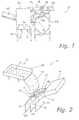
- FIGs. 1-3in general, embodiments of an apparatus 10, particularly a laser sorter, according to the invention are illustrated. It should be appreciated that the apparatus 10 is not limited in its field of use, and has application in any environment wherein it is desired to detect and sort undesired or foreign bodies from a conveyed stream of products, or to sort products according to structural and/or color differences. Apparatus 10 is particularly useful in a food products processing environment wherein the use of laser sorters is well known.
- Figs. 1-3illustrate the basic physical components of a laser sorter according to the invention.
- Apparatus 10may include a cabinet 60 and frame members 58 for housing and supporting the various components.
- Frame members 58 and cabinet 60can take on any manner of configuration to serve their intended purpose.
- the optics packages 54, 56are important features of the invention and will be described in detail below.
- a front optics package 54 and a rear optics package 56are provided to scan products 12 from two directions.
- one optics package and associated control circuitryare all that is necessary.
- Each optics packageincludes at least one light beam generating source 18, preferably at least one laser beam generator 20. Any combination of laser beam generators may be utilized depending on the intended scanning environment of apparatus 10. The number of lasers and their respective wavelength (color) depends on the application (color sorting and/or structure sorting) and products to be scanned.
- the light source (laser(s)) 20produce a relatively narrow beam of light 22 with a single polarization, or a combination of these beams, to detect variations between products 12 according to their structure and/or color.
- a transport device 36is provided to convey a generally steady steam of products 12 through a detection or scanning zone 14 where the products are scanned by the light beam(s).
- the transport device 36includes a vibration or "shaker table 38 mounted on springs 44 or other resilient devices.
- a vibrator 42is incorporated with table 38 to impart a relatively constant "shaking" motion thereto to cause the products 12 to move randomly towards the distribution surface 40.
- the productsare allowed to "free-fall" off the edge of the table 38 and follow their natural trajectory due to gravity through the scanning zone 14.
- This surface 40is a stationary member which is generally convex over at least a portion thereof in the direction of travel of products 12, the curvature of the convex portion being about equal to or slightly less than the free-fall path the products 12 will otherwise follow once they fall off of the end of table 38.
- the shape of surface 40 and the vibrating action of table 38ensure that the products 12 leave the surface 40 and pass through the detection zone 14 in a single layer with substantially a thickness of only one product 12.
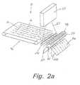
- Fig. 2aillustrates an alternate embodiment wherein products 12 are conveyed along a conveyor 46 running at a speed so as to "propel" the products in "free-flight” across the detection zone 14.
- the optics package 54is positioned so that the products 12 travel through the scanning light beam as they travel along their "free-flight trajectory.
- the productspass through the scanning zone 14 where they are scanned from either one or both sides by any combination of lasers 20 (for example, three lasers per side) at a high scan rate, for example at a rate of up to 2,000 scans per second.
- lasers 20for example, three lasers per side
- a high scan ratefor example at a rate of up to 2,000 scans per second.
- the number of lasers 20 and their respective wavelengths (color)depends on the application and products to be scanned.
- a removal device 48is provided to remove detected foreign bodies or "reject" products 16 from the stream of products 12.
- the removal device 48is defined by a bank 50 of air ejection nozzles supplied by a source of compressed air (or other gas or fluid) 52. With this type of removal device, a plurality of adjacent air ejector nozzles are disposed below and across the scanning zone 14.
- the air ejector nozzle(s) corresponding to the location of the foreign body or irregular product within the width of scanning zone 14is actuated to emit a stream of relatively high pressure gas at a time determined by the control circuitry to correspond to the time at which the foreign body or irregular product passes by the air ejector nozzle(s), the relatively high pressure gas thereby impinging upon and deflecting the foreign body 16 into a reject chute 30.
- the "good" products 12are allowed to follow their trajectory into an accept chute 26 for further processing.
- the chutesmay be defined by any structure, for example by means of simple dividing plates 28.
- Each laser 20produces a concentrated beam 22 of light which passes through a polarizing beam splitter 88. If more than one laser is used, their respective light beams 22 may be combined in a dichroic mirror upstream from polarizing beam splitter 88 to produce one light beam 22 of different colors (wavelengths).
- the operating principles of a polarizing beam splitterare understood by those skilled in the art and a detailed explanation thereof is not necessary for purposes of the present description.
- any irregularity or imperfection in the polarization of light beam 22is removed as light beam 22 passes through the polarizing beam splitter 88.
- Light beam 22 leaving polarizing beam splitter 88is directed to a high speed rotating polygon mirror 90.
- the high speed polygon, mirror 90directs the light beam(s) in a scanning pattern 23 over the full width of the scanning zone 14 towards a reference or background element 24. It may be preferred to utilize a light gate 25 ( Fig. 6 ) between the polygon mirror 90 and background element 24.
- This light gate 25is described in detail in the published PCT application WO 98144335 .
- the light gate 25ensures that the light reflected back to the detectors from the scanned bodies is "independent" of the position of the bodies in the scanning pattern of the light beam(s) 22. In this way, a substantially uniform sensitivity is obtained in scanning products across the full width of scanning pattern 23.
- the light gate 25may be made in the form of a diaphragm having an opening that narrows in the direction of the point of greatest reflected light from the scanned bodies (generally in the middle of the scanning pattern 23). This opening is disposed in a plane perpendicular to the plane in which light beam 22 moves.
- the form and size of the diaphragm openingare chosen so that whenever the light beam 22 is directed towards the products, the signal generated by the detectors receiving the light "returned” by the scanned products is independent of the position of the products within the scanning pattern 23 of the light beam 22.
- Background element 24may be made of various materials depending on the type of objects to be scanned, and is preferably of a color and a translucency generally similar to the desired color and translucency of the particular product 12 being scanned.
- the products 12 to be scannedpass through scanning zone 14 between background element 24 and mirror 90.
- the light beam(s)impact on the products 12 and a part of the light is reflected back to mirror 90 and polarizing beam splitter 88.
- the reflected lightcontains light having the same polarization as the incident light beam and light of perpendicular polarizations from the scanned bodies.
- the same polarized lightis not particularly useful to the processing circuitry and may even mask certain useful information about the scanned products.
- Polarizing beam splitter 88 wiiisplit the reflected light into two polarization directions, one having the same polarization as the incident laser light, the polarization of which had been initially further aligned by the passage of the initial concentrated beam 22 of light from laser 20 through the same polarizing beam splitter 88, and the other having a 90 degree polarization (cross-polarized light) with respect to the incident laser light.
- the same polarized reflected lightis passed directly through beam splitter 88 and is not further used.
- polarizing beam splitter 88may be thought of as serving a "filtering" function in that it filters the same polarized light from the reflected light.
- the cross polarized light from beam splitter 88is directed to a focusing lens 92 and then to a non-polarizing beam splitter 82 (sometimes referred to in the art as a "50/50 beam splitter").
- Beam splitter 82passes about 50% of the cross polarized reflected light 84 to a first detector 62, and about 50% (86) to a second detector 66.
- the entire field of the cross polarized lightis directed to both detectors 62,66 but at half of the magnitude or strength of the light passing through focusing lens 92.
- First detector 62has a field of view with a large enough diameter so that essentially all of the cross polarized light reflected from the scanned products, including the light diffused into translucent products (scattered light) and the relatively intense center light reflected from the point of impingement of the incident laser light on the product.
- the field of view of first detector 62is defined by an upstream defining member 74, such as a plate or diaphragm member 76 having a relatively large aperture or hole defined therethrough with a diameter that thus defines the diameter of the field of view.
- First detector 62produces a control signal "B" proportional to the entire reflected cross polarized light field. Signal “B” is passed to an adjustable gain op-amp 94 which produces an adjusted control signal "K 2 B.”
- Second detector 66has a field of view corresponding in size essentially to the cross-sectional diameter of the incident scanning light beam. Detector 66 thus senses only the relatively intense direct reflected light from the point of impact of the incident light beam on the products.
- the field of view of second detector 66is defined by an upstream defining member 78, such as a plate or diaphragm member 80 having a hole or aperture defined therethrough with a diameter corresponding to the cross-sectional diameter of the incident laser light beam.
- Second detector 66produces an output signal "A" proportional to the direct reflected light. Signal A" is passed to a second adjustable op-amp 96 which produces an adjusted control signal K 1 A.
- Fig. 4illustrates fundamental principles relating to the two detector configuration of Fig. 3 .
- Fig. 4shows three types of scanned bodies.
- the first bodyis a relatively translucent body. When the concentrated scanning light beam of a given diameter impinges upon the translucent body, the light will diffuse into the body.
- Circle 64 on the scanned bodiesrepresents the field of view of the first sensor 62 (corresponds to the aperture size of the hole in diaphragm 76). This field is substantially larger than the circle 68, which corresponds to the field of view of second sensor 66.
- first sensor 62is sensitive to substantially all of the light reflected from the body, including the diffused light and the direct light reflected from the point of impact of the scanning beam.
- the field of view 68 of the second sensor 66has a diameter corresponding essentially to that of the impinging scanning light beam. The second sensor is thus sensitive only to the light reflected from the point of impingement of the laser beam on the body.
- the second scanned body in Fig. 4is about 50% as translucent as the first body.
- the strength of signal "A”is thus greater than that for the first translucent body.
- the strength of signals "B”is slightly higher than signal "A.”
- the third bodyis a substantially non-translucent body, such as a stone, piece of plant stem, or other hard body. With this type of object, little if any light will diffuse into the body and the strength of signal "A" will be greatest. The strength of signal "B” will be about the same as signal "A” since sensor 62 will detect all of the direct reflected light.
- Signal Bis less structure dependent than signal "A” since the signal strength is generally the same regardless of the structure or texture of the scanned bodies.
- any change in the strength of signal "B”is a result of color effects, or "gray scale,” of the scanned bodies.
- signal Bmay be used by the control circuitry 34 ( Fig. 3 ) to sort/scan objects by color or gray scale only.
- signal “A”is both color and structure dependent. As discussed above with respect to Fig. 4 , for scanned objects of the same color, signal “A” will vary in strength depending on the translucency (structure or texture) of the bodies. For scanned bodies of the same structure (translucency), signal “A” will also vary depending on color changes of the bodies. For example signal “A” will be greater for a “white” scanned body as compared to a “brown” body having the identical structure. Signal “A” may thus be used by its associated control circuitry 37 to scan based on structure and color.
- Signal "A”is also useful in scanning for relatively smaii objects, for example pebbles or shells that are smaller than the field of view utilized to define "blind spots” utilized to define the field of view in certain prior art laser sorters, for example the sorter described in U.S. Patent No. 4,723,659 .
- the diffused light portion of signal "B”is "indirectly” determined from a difference of signals "A” and "B.”
- This differencecan be generated by, for example a conventional electronic signal differencing device or op-amp 72.
- Op-amp 72electronically subtracts signal K 1 A corresponding to the direct reflected light from the impingement point of the scanning beam from signal K 2 B corresponding to the entire light field detected by sensor 62 so that the resulting signal corresponds essentially only to the diffused light portion of the reflected beam.
- This signalis passed to its associated control circuitry 35 to be acted upon by the air ejector nozzles.
- Fig. 5represents a scanning principle of the invention based on the difference signal (K 2 B-K 1 A).
- Each of the signals "A” and “B”define an axis or the scanning limits of the system for scanning based on the difference signal from op-amp 72.
- the line “C”is defined by the difference signal and represents the threshold between "good” and “bad” scanned bodies. This threshold can be infinitely varied by adjusting the individual gain control opamps 94,96 of the respective signals depending on the scanning environment and types of bodies to be scanned.
- any combination of the three signals A, B, or Cmay be utilized by the control circuitry to actuate the air ejector nozzles when a foreign body or reject product is detected in the stream of scanned bodies.
- signals A and Bare separately generated and processed allows the apparatus 10 according to the invention to perform advantageous sorting functions generally not possible with conventional laser sorters.
- Apparatus 10can compensate for edge or shadow effects (as described in U.S. Patent No.
- 4,634,881can differentiate or sort by color; can detect and sort relatively small impurities or objects; has a relatively great degree of threshold detection adjustability or "fine tuning" because of the ability for separate gain control of signals A and B: and can reliably detect and sort glass and similar materials from scanned bodies.
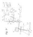
- Fig. 6is a diagrammatic and partial operational view of such an embodiment of an optics package 54 (56) according to the invention.
- the package componentsare preferably mounted on a relatively stiff and hard mounting board or member 100.
- This member 100is in turn mounted within the respective optics package 54 (56).
- the componentscan be mounted on member 100 in virtually any pattern, and that any configuration or combination of mirrors or the like may be utilized to direct the light beam to the respective components.
- the present inventionis not limited to any particular configuration of the components and the embodiment of Fig. 6 is presented as an example only.
- an infrared laser 102, a red laser 104, and a green laser 106are utilized.
- the green and red lasersare used to sort scanned objects by specific color, and the infrared laser is used to sort by structure.
- a dichroic mirror 108combines the light from lasers 102 and 104 into a single light beam. This beam is combined with the beam from laser 106 by means of another dichroic mirror 107 into a single light beam 22. This beam 22 is directed to polarizing beam splitter 88.
- Polarizing beam splitter 88refines/assures the polarization of the light beam 22, thereby guaranteeing that the discarded reflected light from the scanned bodies is only that light for which the polarization matched that of the incident beam. From the polarizing beam splitter 88, light beam 22 is directed to the rotating polygon mirror 90 and reflected by this rotating polygon mirror 90 through light gate 25 in its scanning patter across the scanning zone.
- the light returned from the scanned productsis represented in dashed lines in Fig. 6 .
- a filtering device(not shown) may be used to filter out any ambient light or other unwanted light from the returned light.
- the return lightis reflected from polygon mirror 90 to polarizing beam splitter 88. As discussed, the return light having the same polarization of the incident beam 22 is passed through polarizing beam splitter 88 and "discarded.”
- the returned cross polarized light beam(compared to the incident light beam 22) is directed by a polarizing beam splitter mirror through a focusing lens 92 to a dichroic mirror 120.
- Dichroic mirror 120reflects the returned cross polarized light of the green laser 106 and passes the returned cross polarized light of the red and infrared laser.
- the reflected light from dichroic mirror 120passes through a polarizer 122 which refines/assures the green light and is directed to a "green" light receiver 126.
- the light that passes dichroic mirror 120is directed to another dichroic mirror 121 which reflects the returned cross polarized light from the red laser 104 and passes the returned cross polarized light from the infrared laser 102.
- the red lightis directed through a polarizing beam splitter 123 to a "red" light receiver 128.
- the green and red light receiversproduce signals proportional to the amount of green or red light they receive. By comparison with threshold values, these signals can thus be used to identify and sort the scanned bodies by color variations.
- the light beam passed through dichroic mirror 121is passed through a polarizer beam splitter 130 to a 50/50 beam splitter 132. About 50% of the light beam incident on beam splitter 132 is passed to small aperture receiver 134 and about 50% of the incident beam is passed to a large aperture receiver 136. These receivers are explained with reference to Fig. 3 .
- Fig. 6The configuration of Fig. 6 is particularly useful when an infrared laser is used as laser 102 for structure sorting capability.
- the separate signals from receivers 134 and 136can provide the capability to sort also by color variations, it certain situations it may not be preferred to use infrared light for sorting by specific visible colors.
Landscapes
- Investigating Materials By The Use Of Optical Means Adapted For Particular Applications (AREA)
- Sorting Of Articles (AREA)
- Geophysics And Detection Of Objects (AREA)
Abstract
Description
- The present invention relates to an apparatus and a method for scanning any manner of conveyed products with a light beam, particularly a laser, in order to detect and remove impurities or irregular bodies in the stream of products.
- Laser scanners or sorters are known in the art. For example, Belgian Electronic Sorting Technology (BEST) manufactures and markets (not in the U.S.) laser sorters identified as the LS9000 and the ARGUS. The LS9000 utilizes a combination of lasers to produce narrow beams of light to detect even slight variations between products according to their structure and/or color. Another company, Barco, manufactures and sells a line of laser sorting machines, including the ES6000i and ES V1720, advertised as capable of sorting products by color and texture. The fundamental principles of laser sorting technology are well known and understood by those skilled in the art.
- The
document WO 92/14556 U.S. Patent Nos. 4,634,881 and4,723,659 describe and claim embodiments of laser sorters. The '881 patent describes a device that utilizes a laser for directing a concentrated light beam in a scanning pattern through which translucent bodies are conveyed. A background device is spaced from the laser and is illuminated by a separate source of light independent of the laser beam. A receiver receives the light reflected from the background member and from the translucent bodies moving through the laser scanning beam, as well as the light from the independent light source that illuminates the background member. The receiver produces an output signal that changes when an impurity enters the concentrated scanning light beam. This signal is used to operate a device that removes the impurity from the stream of translucent bodies.- The '659 patent relates to a similar device and includes transport devices for moving a plurality of rows of translucent bodies, such as french cut potatoes, through the light beam. The transport devices are configured to move parallel rows of the translucent bodies simultaneously through the light beam path. The background element is not separately illuminated and is formed of a material that causes impinging light from the laser to be diffused within the background element in a manner similar to diffusion of the light in a translucent body. A receiver has a field of view larger than the cross-sectional area of the light beam and receives the light reflected from the background element and from the translucent bodies moving through the light beam. The receiver is made insensitive to light in the part of its field of view that corresponds with the point of impingement of the light beam on the translucent bodies. The receiver includes a photosensitive detector wherein the optical center point of the detector is made blind by means of a back spot so that the detector will not "see" the light reflected from the point of impingement of the laser beam on the translucent bodies. The patent describes that the detector may also receive reflected light from a mirror having a small hole defined therethrough that corresponds to the point of impingement of the laser beam on the translucent bodies. Thus, the reflected light from the point of impingement passes through the small hole in the mirror and is not reflected to the detector.
- The present invention relates to an improvement upon the known systems and methods for sorting and scanning products with laser beams and provides distinct advantages over the conventional systems and methods.
- It is a primary object of the principal invention to provide an improved laser sorting machine and method.
- It is also a principal object of the present invention to provide a laser sorting machine and method that can sort various types of products by a combination of different signals so that the products can be sorted by color, structure, or a combination of color and structure.
- Additional objects and advantages of the invention will be set forth in part in the following description, or may be obvious from the description, or may be learned through practice of the invention.
- In accordance with the invention, an apparatus is provided for sorting products moving through a detection zone wherein it is desired to detect and remove irregularities or foreign objects from the product stream. The invention is not limited to use for any particular type of product, and is particularly useful for scanning food products, such as raisins, vegetables, nuts, shellfish, etc. The invention is useful in any application wherein irregular products or foreign objects in the product stream can be detected by texture and/or color differences.
- The apparatus includes a light source, preferably at least one laser or a combination of lasers. The light source directs a concentrated light beam having a relatively small cross-sectional area towards a scanning zone. The products move through the scanning zone and are impinged upon by the light beam. The products can be conveyed or propelled through the scanning zone by various devices. For example, in a "free-fall" configuration, the scanned products are allowed to "fall" from a vibrating or "shaker" table. The products free-fall essentially along their natural trajectory through the scanning zone. In an alternative embodiment, the products are propelled through the scanning zone in a "free-flight" configuration wherein a conveyor moving at a relatively high speed propels the objects across the scanning zone.
- The light reflected from the products includes light directly reflected from the point of impingement of the light beam on the products and light that is diffusely reflected from the area surrounding the impingement point due to diffusion or scattering of the light beam into the product. The degree of diffusion of the light into the product depends on the translucency of the product. For example, if the scanned body is a relatively non-translucent body (such as certain stones), relatively little light will be diffused into the product and substantially all of the reflected light is directly reflected from the point of impingement of the light beam on the product. On the other hand, if the scanned product is a relatively translucent body (such as certain food products), a large portion of the impinging light will diffuse into the translucent body and will be reflected as diffused or scattered light from the area surrounding the impingement point.
- A plurality of different wavelength (color) light source and detectors may be provided and utilized according to the desired sorting function. For example, specific visible color lasers and respective detectors may be For provided for sorting the scanned objects by color alone. Other lasers (i.e. infrared) and respective detectors may be provided alone or in combination with the "color" detectors to sort by structure.
- In one embodiment, a first detector is disposed to receive the light reflected back from the scanned products. The first detector has a field of view larger than the cross-sectional area of the light beam so as to be sensitive to substantially all of the direct and diffused reflected light from the products. This first detector generates a first signal corresponding to the received total (direct and diffused) reflected light.
- A second detector is disposed to receive the reflected light back from the products. The second detector has a different ('"second") field of view generally equal to the cross-sectional area of the light beam. In this way, the second detector is sensitive to substantially only the direct reflected light from the products and generates a second signal corresponding thereto.
- Control circuitry is provided in operable communication with the first and second detectors to receive the first and second signals. The control circuitry generates control signals based on either of the signals individually or on a difference of the signals to sort the scanned products by any combination of color or texture depending on the exact signal or combination of signals used.
- A beam splitter may be utilized upstream of the first and second detection devices. The beam splitter is disposed to split the reflected light from the products into a first beam directed to the first detector and a second beam directed to the second detector.
- For example, a polarizing beam splitter may be disposed between the scanning zone and the detection devices. The polarizing beam splitter cross-poiarizes the reflected light received from the products with respect to a given polarization of the incident light beam and directs this cross-polarized light to the detectors. The reflected light received from the products having the same polarization as the light beam generally does not contain useful information and will pass through the beam splitter and be directed away from the detectors.
- The first and second detector configuration may be utilized with a laser to sort by structure alone, or in combination with other wavelength lasers and respective detectors to provide additional color sorting capabilities. The first and second detector configuration may also be utilized to sort by color as well as structure, as discussed in greater detail herein. It should be appreciated that any combination of lasers, mirrors, focusing lenses, and beam splitters may be configured to analyze the reflected light beam by a number of different detector types to sort by color and/or structure.
- The apparatus also preferably includes a removal mechanism, such as a bank of air ejectors disposed generally across the scanning zone, controlled by the control circuitry and acting in response to the control signals to remove unwanted objects or irregularities from the scanned products. For example, in the embodiment wherein the removal mechanism comprises a bank of air ejectors, the air ejectors are of a number and location so as to be able to remove an object from the products from anywhere across the width of the light beam scanning zone.
- The scanning zone may be defined by a rotating multi-faceted mirror disposed between the light source and the scanning zone. The mirror directs the light beam in a high speed scanning pattern that defines the width of the scanning zone. The apparatus and method according to the invention will be described in greater detail below through use of the appended figures.
Figure 1 is a diagrammatic perspective view of a laser sorter according to the present invention,Figure 2 is an operational illustration showing basic features of the laser sorter according to one embodiment of the invention;Figure 2a is an operational view showing basic features of an alternative embodiment of the laser sorter according to the invention;Figure 3 illustrates the operating principles of the system according to the present invention;Figure 4 is a sketch illustrating the principles of operation of the laser sorter according to the present invention;Figure 5 is a diagram illustrating an operating principle of the present invention; andFigure 6 is a diagrammatic view illustrating the components of an embodiment of the optics package according to the invention.- Reference will now be made in detail to the presently preferred embodiments of the invention, one or more examples of which are illustrated in the drawings. Each example is provided by way of explanation of the invention, and not meant as a limitation of the invention. For example, features illustrated or described as part of one embodiment can be used on another embodiment to yield a still further embodiment. It is intended that the present application include such modifications and variations as come within the scope and spirit of the invention.
- The published
PCT applications WO 98/31477 WO 98/44335 - Referring to
Figs. 1-3 in general, embodiments of anapparatus 10, particularly a laser sorter, according to the invention are illustrated. It should be appreciated that theapparatus 10 is not limited in its field of use, and has application in any environment wherein it is desired to detect and sort undesired or foreign bodies from a conveyed stream of products, or to sort products according to structural and/or color differences.Apparatus 10 is particularly useful in a food products processing environment wherein the use of laser sorters is well known. Figs. 1-3 illustrate the basic physical components of a laser sorter according to the invention.Apparatus 10 may include acabinet 60 andframe members 58 for housing and supporting the various components.Frame members 58 andcabinet 60 can take on any manner of configuration to serve their intended purpose.- The optics packages 54, 56 are important features of the invention and will be described in detail below. In the embodiment illustrated, a
front optics package 54 and a rear optics package 56 are provided to scanproducts 12 from two directions. However, one optics package and associated control circuitry are all that is necessary. Each optics package includes at least one lightbeam generating source 18, preferably at least onelaser beam generator 20. Any combination of laser beam generators may be utilized depending on the intended scanning environment ofapparatus 10. The number of lasers and their respective wavelength (color) depends on the application (color sorting and/or structure sorting) and products to be scanned. The light source (laser(s)) 20 produce a relatively narrow beam of light 22 with a single polarization, or a combination of these beams, to detect variations betweenproducts 12 according to their structure and/or color. - A
transport device 36 is provided to convey a generally steady steam ofproducts 12 through a detection orscanning zone 14 where the products are scanned by the light beam(s). In the embodiment illustrated inFigs. 1-2 , thetransport device 36 includes a vibration or "shaker table 38 mounted onsprings 44 or other resilient devices. Avibrator 42 is incorporated with table 38 to impart a relatively constant "shaking" motion thereto to cause theproducts 12 to move randomly towards thedistribution surface 40. The products are allowed to "free-fall" off the edge of the table 38 and follow their natural trajectory due to gravity through thescanning zone 14. - It may be desired to provide a
distribution surface 40 in the free-fall path. Thissurface 40 is a stationary member which is generally convex over at least a portion thereof in the direction of travel ofproducts 12, the curvature of the convex portion being about equal to or slightly less than the free-fall path theproducts 12 will otherwise follow once they fall off of the end of table 38. The shape ofsurface 40 and the vibrating action of table 38 ensure that theproducts 12 leave thesurface 40 and pass through thedetection zone 14 in a single layer with substantially a thickness of only oneproduct 12. A detailed explanation ofdistribution surface 40 is provided in the publishedPCT application WO 98/31477 Fig. 2a illustrates an alternate embodiment whereinproducts 12 are conveyed along a conveyor 46 running at a speed so as to "propel" the products in "free-flight" across thedetection zone 14. In this embodiment, theoptics package 54 is positioned so that theproducts 12 travel through the scanning light beam as they travel along their "free-flight trajectory.- The products pass through the
scanning zone 14 where they are scanned from either one or both sides by any combination of lasers 20 (for example, three lasers per side) at a high scan rate, for example at a rate of up to 2,000 scans per second. As mentioned, the number oflasers 20 and their respective wavelengths (color) depends on the application and products to be scanned. - Immediately downstream of
scanning zone 14, aremoval device 48 is provided to remove detected foreign bodies or "reject"products 16 from the stream ofproducts 12. In the illustrated embodiments, theremoval device 48 is defined by abank 50 of air ejection nozzles supplied by a source of compressed air (or other gas or fluid) 52. With this type of removal device, a plurality of adjacent air ejector nozzles are disposed below and across thescanning zone 14. As explained in grater detail below, if the control circuitry detects that a foreign body or irregular product has passed through the scanning zone, the air ejector nozzle(s) corresponding to the location of the foreign body or irregular product within the width ofscanning zone 14 is actuated to emit a stream of relatively high pressure gas at a time determined by the control circuitry to correspond to the time at which the foreign body or irregular product passes by the air ejector nozzle(s), the relatively high pressure gas thereby impinging upon and deflecting theforeign body 16 into areject chute 30. The "good"products 12 are allowed to follow their trajectory into an acceptchute 26 for further processing. The chutes may be defined by any structure, for example by means ofsimple dividing plates 28. - The scanning and detection operation is illustrated conceptually in
Fig. 3 . It should be appreciated that the combination of element shown inFig. 3 is but an example of one embodiment of the invention. Those skilled in the art may devise other working configurations within the scope and spirit of the invention. Eachlaser 20 produces aconcentrated beam 22 of light which passes through apolarizing beam splitter 88. If more than one laser is used, their respective light beams 22 may be combined in a dichroic mirror upstream frompolarizing beam splitter 88 to produce onelight beam 22 of different colors (wavelengths). The operating principles of a polarizing beam splitter are understood by those skilled in the art and a detailed explanation thereof is not necessary for purposes of the present description. In general, although laser light is already polarized, and although the polarization of thelight beam 22 is oriented in such a way that it corresponds with the transmission polarization direction of the beam splitter, any irregularity or imperfection in the polarization oflight beam 22 is removed aslight beam 22 passes through thepolarizing beam splitter 88.Light beam 22 leavingpolarizing beam splitter 88 is directed to a high speed rotatingpolygon mirror 90. - The high speed polygon,
mirror 90 directs the light beam(s) in ascanning pattern 23 over the full width of thescanning zone 14 towards a reference orbackground element 24. it may be preferred to utilize a light gate 25 (Fig. 6 ) between thepolygon mirror 90 andbackground element 24. Thislight gate 25 is described in detail in the publishedPCT application WO 98144335 light gate 25 ensures that the light reflected back to the detectors from the scanned bodies is "independent" of the position of the bodies in the scanning pattern of the light beam(s) 22. In this way, a substantially uniform sensitivity is obtained in scanning products across the full width ofscanning pattern 23. Thelight gate 25 may be made in the form of a diaphragm having an opening that narrows in the direction of the point of greatest reflected light from the scanned bodies (generally in the middle of the scanning pattern 23). This opening is disposed in a plane perpendicular to the plane in whichlight beam 22 moves. The form and size of the diaphragm opening are chosen so that whenever thelight beam 22 is directed towards the products, the signal generated by the detectors receiving the light "returned" by the scanned products is independent of the position of the products within thescanning pattern 23 of thelight beam 22. Background element 24 may be made of various materials depending on the type of objects to be scanned, and is preferably of a color and a translucency generally similar to the desired color and translucency of theparticular product 12 being scanned. Theproducts 12 to be scanned pass throughscanning zone 14 betweenbackground element 24 andmirror 90.- In the
scanning zone 14, the light beam(s) impact on theproducts 12 and a part of the light is reflected back tomirror 90 andpolarizing beam splitter 88. The reflected light contains light having the same polarization as the incident light beam and light of perpendicular polarizations from the scanned bodies. The same polarized light is not particularly useful to the processing circuitry and may even mask certain useful information about the scanned products.Polarizing beam splitter 88 wiii split the reflected light into two polarization directions, one having the same polarization as the incident laser light, the polarization of which had been initially further aligned by the passage of the initialconcentrated beam 22 of light fromlaser 20 through the samepolarizing beam splitter 88, and the other having a 90 degree polarization (cross-polarized light) with respect to the incident laser light. The same polarized reflected light is passed directly throughbeam splitter 88 and is not further used. Thus,polarizing beam splitter 88 may be thought of as serving a "filtering" function in that it filters the same polarized light from the reflected light. - The cross polarized light from
beam splitter 88 is directed to a focusinglens 92 and then to a non-polarizing beam splitter 82 (sometimes referred to in the art as a "50/50 beam splitter").Beam splitter 82 passes about 50% of the cross polarized reflected light 84 to afirst detector 62, and about 50% (86) to asecond detector 66. The entire field of the cross polarized light is directed to bothdetectors lens 92. - Each of the
detectors First detector 62 has a field of view with a large enough diameter so that essentially all of the cross polarized light reflected from the scanned products, including the light diffused into translucent products (scattered light) and the relatively intense center light reflected from the point of impingement of the incident laser light on the product. The field of view offirst detector 62 is defined by an upstream definingmember 74, such as a plate ordiaphragm member 76 having a relatively large aperture or hole defined therethrough with a diameter that thus defines the diameter of the field of view.First detector 62 produces a control signal "B" proportional to the entire reflected cross polarized light field. Signal "B" is passed to an adjustable gain op-amp 94 which produces an adjusted control signal "K2B." Second detector 66 has a field of view corresponding in size essentially to the cross-sectional diameter of the incident scanning light beam.Detector 66 thus senses only the relatively intense direct reflected light from the point of impact of the incident light beam on the products. The field of view ofsecond detector 66 is defined by an upstream definingmember 78, such as a plate ordiaphragm member 80 having a hole or aperture defined therethrough with a diameter corresponding to the cross-sectional diameter of the incident laser light beam.Second detector 66 produces an output signal "A" proportional to the direct reflected light. Signal A" is passed to a second adjustable op-amp 96 which produces an adjusted control signal K1A.Fig. 4 illustrates fundamental principles relating to the two detector configuration ofFig. 3 .Fig. 4 shows three types of scanned bodies. The first body is a relatively translucent body. When the concentrated scanning light beam of a given diameter impinges upon the translucent body, the light will diffuse into the body.Circle 64 on the scanned bodies represents the field of view of the first sensor 62 (corresponds to the aperture size of the hole in diaphragm 76). This field is substantially larger than thecircle 68, which corresponds to the field of view ofsecond sensor 66. Thus, it should be appreciated thatfirst sensor 62 is sensitive to substantially all of the light reflected from the body, including the diffused light and the direct light reflected from the point of impact of the scanning beam. The field ofview 68 of thesecond sensor 66 has a diameter corresponding essentially to that of the impinging scanning light beam. The second sensor is thus sensitive only to the light reflected from the point of impingement of the laser beam on the body.- Referring to the first "translucent" body of
Fig. 4 , it can be seen that a substantial portion of the impinging light diffuses or scatters into the body. The signal strength for signal "A" is thus relatively small since only a relatively small amount of light is reflected directly back from the impingement point. The signal strength of signal "B" is relatively higher than signal "A" since the direct reflected light and diffused light are sensed byfirst sensor 62. - The second scanned body in
Fig. 4 is about 50% as translucent as the first body. Here, it can be seen that less light is diffused into the surrounding area of the body and more light is reflected directly back from the impingement point of the scanning beam. The strength of signal "A" is thus greater than that for the first translucent body. The strength of signals "B" is slightly higher than signal "A." The third body is a substantially non-translucent body, such as a stone, piece of plant stem, or other hard body. With this type of object, little if any light will diffuse into the body and the strength of signal "A" will be greatest. The strength of signal "B" will be about the same as signal "A" sincesensor 62 will detect all of the direct reflected light. - Recognition of the principles shown in
Fig. 4 and utilization of the signals A and B individually or the difference between signals A and B provides the present invention with the ability to sort scanned objects by color, structure (texture), or a combination of color and structure. For example, signal "B" is less structure dependent than signal "A" since the signal strength is generally the same regardless of the structure or texture of the scanned bodies. Thus, any change in the strength of signal "B" is a result of color effects, or "gray scale," of the scanned bodies. In other words a change in the strength of signal B would indicate that a body of a different color has been scanned as compared to the other scanned bodies. Thus, signal B may be used by the control circuitry 34 (Fig. 3 ) to sort/scan objects by color or gray scale only. - On the other hand, signal "A" is both color and structure dependent. As discussed above with respect to
Fig. 4 , for scanned objects of the same color, signal "A" will vary in strength depending on the translucency (structure or texture) of the bodies. For scanned bodies of the same structure (translucency), signal "A" will also vary depending on color changes of the bodies. For example signal "A" will be greater for a "white" scanned body as compared to a "brown" body having the identical structure. Signal "A" may thus be used by its associatedcontrol circuitry 37 to scan based on structure and color. Signal "A" is also useful in scanning for relatively smaii objects, for example pebbles or shells that are smaller than the field of view utilized to define "blind spots" utilized to define the field of view in certain prior art laser sorters, for example the sorter described inU.S. Patent No. 4,723,659 . - To sort based on the structure of the scanned bodies alone, the diffused light portion of signal "B" is "indirectly" determined from a difference of signals "A" and "B." This difference can be generated by, for example a conventional electronic signal differencing device or op-
amp 72. Op-amp 72 electronically subtracts signal K1A corresponding to the direct reflected light from the impingement point of the scanning beam from signal K2B corresponding to the entire light field detected bysensor 62 so that the resulting signal corresponds essentially only to the diffused light portion of the reflected beam. This signal is passed to its associatedcontrol circuitry 35 to be acted upon by the air ejector nozzles. Fig. 5 represents a scanning principle of the invention based on the difference signal (K2B-K1A). Each of the signals "A" and "B" define an axis or the scanning limits of the system for scanning based on the difference signal from op-amp 72. The line "C" is defined by the difference signal and represents the threshold between "good" and "bad" scanned bodies. This threshold can be infinitely varied by adjusting the individualgain control opamps 94,96 of the respective signals depending on the scanning environment and types of bodies to be scanned.- Thus, it should be appreciated that any combination of the three signals A, B, or C (difference signal) may be utilized by the control circuitry to actuate the air ejector nozzles when a foreign body or reject product is detected in the stream of scanned bodies. The fact that signals A and B are separately generated and processed allows the
apparatus 10 according to the invention to perform advantageous sorting functions generally not possible with conventional laser sorters.Apparatus 10 can compensate for edge or shadow effects (as described inU.S. Patent No. 4,634,881 ); can differentiate or sort by color; can detect and sort relatively small impurities or objects; has a relatively great degree of threshold detection adjustability or "fine tuning" because of the ability for separate gain control of signals A and B: and can reliably detect and sort glass and similar materials from scanned bodies. - In certain applications, it may also be desired to sort by specific visible color variations in the scanned products by using a particular color laser and respective detector in addition to the detector configuration of
Fig. 3 .Fig. 6 is a diagrammatic and partial operational view of such an embodiment of an optics package 54 (56) according to the invention. The package components are preferably mounted on a relatively stiff and hard mounting board ormember 100. Thismember 100 is in turn mounted within the respective optics package 54 (56). It should be appreciated that the components can be mounted onmember 100 in virtually any pattern, and that any configuration or combination of mirrors or the like may be utilized to direct the light beam to the respective components. The present invention is not limited to any particular configuration of the components and the embodiment ofFig. 6 is presented as an example only. - In the embodiment of
Fig. 6 , aninfrared laser 102, ared laser 104, and agreen laser 106 are utilized. The green and red lasers are used to sort scanned objects by specific color, and the infrared laser is used to sort by structure. Adichroic mirror 108 combines the light fromlasers laser 106 by means of anotherdichroic mirror 107 into asingle light beam 22. Thisbeam 22 is directed topolarizing beam splitter 88.Polarizing beam splitter 88 refines/assures the polarization of thelight beam 22, thereby guaranteeing that the discarded reflected light from the scanned bodies is only that light for which the polarization matched that of the incident beam. From thepolarizing beam splitter 88,light beam 22 is directed to therotating polygon mirror 90 and reflected by thisrotating polygon mirror 90 throughlight gate 25 in its scanning patter across the scanning zone. - The light returned from the scanned products is represented in dashed lines in
Fig. 6 . A filtering device (not shown) may be used to filter out any ambient light or other unwanted light from the returned light. The return light is reflected frompolygon mirror 90 topolarizing beam splitter 88. As discussed, the return light having the same polarization of theincident beam 22 is passed throughpolarizing beam splitter 88 and "discarded." The returned cross polarized light beam (compared to the incident light beam 22) is directed by a polarizing beam splitter mirror through a focusinglens 92 to adichroic mirror 120.Dichroic mirror 120 reflects the returned cross polarized light of thegreen laser 106 and passes the returned cross polarized light of the red and infrared laser. The reflected light fromdichroic mirror 120 passes through apolarizer 122 which refines/assures the green light and is directed to a "green"light receiver 126. The light that passesdichroic mirror 120 is directed to anotherdichroic mirror 121 which reflects the returned cross polarized light from thered laser 104 and passes the returned cross polarized light from theinfrared laser 102. The red light is directed through apolarizing beam splitter 123 to a "red"light receiver 128. The green and red light receivers produce signals proportional to the amount of green or red light they receive. By comparison with threshold values, these signals can thus be used to identify and sort the scanned bodies by color variations. - The light beam passed through
dichroic mirror 121 is passed through apolarizer beam splitter 130 to a 50/50beam splitter 132. About 50% of the light beam incident onbeam splitter 132 is passed tosmall aperture receiver 134 and about 50% of the incident beam is passed to alarge aperture receiver 136. These receivers are explained with reference toFig. 3 . - The configuration of
Fig. 6 is particularly useful when an infrared laser is used aslaser 102 for structure sorting capability. Although, as discussed above with respect toFig. 3 , the separate signals fromreceivers
Claims (32)
- An apparatus for detecting irregular or foreign objects (16) in products (12) moving through a scanning zone (14), said apparatus comprising:a light source (18), said light source (18) directing a concentrated light beam (22) having a given cross sectional area towards a scanning zone (14) wherein said products (12) move through said scanning zone (14) and are impinged upon by said light beam (22), said light being directly reflected from generally the impingement point of said light beam (22) on said products (12) and diffusely reflected from an area around said impingement point due to diffusion of said light beam into said products (12);a first detector (62) disposed to receive reflected light back from said products (12), said first detector (62) having a first field (64) of view larger than said light beam (22) cross sectional area wherein said first detector (62) is sensitive to substantially all of said direct and diffused reflected light from said products (12) and generates a first signal corresponding thereto;a second detector (66) disposed to receive reflected light back from said products (12), said second detector (66) having a second field of view (68) generally equal to said cross sectional area of said light beam (22) wherein said second detector (66) is sensitive to substantially only said direct reflected light from said products (12) and generates a second signal corresponding thereto; andcontrol circuitry (34,35,37) in operable communication with said first and second detectors (62,66) to receive said first and second signals and generate control signals based on either of said signals individually or a difference of said signals.
- The apparatus as in claim 1, further comprising a removal mechanism (48) controlled by said control signals and configured to remove objects (16) from said products (12) in response thereto.
- The apparatus as in claim 2, wherein said removal mechanism comprises a bank of air ejectors (50) disposed generally across said scanning zone (14), said air ejectors being of a number and location so as to be able to remove an object (16) from said products (12) from anywhere across a width of said scanning zone.
- The apparatus as in claim 1, wherein said control circuitry comprises a differencing device (72) in receipt of said first and second signals, said differencing device (72) generating a control signal from a difference of said first and second signals that corresponds essentially to only said diffuse reflected light.
- The apparatus as in claim 1, further comprising a first defining member (74) disposed operably before said first detector (62), said first defining member (74) defining the size of said first field of view (64), and a second defining member (78) disposed operably before said second detector (66), said second defining member (78) defining the size of said second field of view (68).
- The apparatus as in claim 5, wherein said first and second defining members (74,78) comprise diaphragm devices (76,80) having apertures therethrough of a size to define said first and second field of views (64,68) respectively.
- The apparatus as in claim 1, further comprising a beam splitter device (82) disposed operably before said first and second detection devices, said beam splitter (82) splitting reflected light from said products (12) into a first split beam directed to said first detector (62) and a second split beam directed to said second detector (66).
- The apparatus as in claim 1, further comprising a polarizing beam splitter (88) operably disposed between said scanning zone and said detection devices, said polarizing beam splitter (88) cross polarizing reflected light received from said products with respect to a given polarization of said light beam and directing said cross polarized light to said detectors (62,66), and passing reflected light received from said products (12) of a same polarization as said light beam (22) away from said detectors (62,66).
- The apparatus as in claim 8, wherein said polarizing beam splitter (88) is disposed between said light source (18) and said scanning zone (14) so that said concentrated light beam (22) of a given polarization passes through said polarizing beam splitter (88) prior to impinging on said products (12).
- The apparatus as in claim 1, further comprising a rotating multi-faceted mirror (90) disposed between said light source (18) and said scanning zone (14), said multi-faceted mirror (90) directing said light beam (22) in a scanning pattern (23) across the width of said scanning zone (14).
- The apparatus as in claim 1, wherein said light source (18) comprises at least one laser beam generator (20.102.104.106).
- The apparatus as in claim 1, wherein said light source (20) comprises at least two laser beam generators (20,102,104,106), and said concentrated light beam (22) comprises a combination of at least two laser beams of different wavelengths.
- The apparatus as in claim 1, further comprising a vibrating table device (38) disposed to receive said products (12) and move said products (12) towards said scanning zone (14), said scanning zone (14) disposed below and adjacent to a forward edge of said vibrating table (38) wherein said products (12) substantially fall from said vibrating table (38) and pass through said scanning zone (14) in a free fall path.
- An apparatus for sorting products moving through a detection zone (14) wherein irregularities or foreign objects (16) in the products (12) are detected and removed, said apparatus comprising:a light source (18), said light source (18) directing a concentrated light beam (22) having a given cross sectional area towards a scanning zone (14) wherein said products (12) move in a mass through said scanning zone (14) and are impinged upon by said light beam (22), said light being directly reflected from generally the impingement point of said light beam (22) on said products (12) and diffusely reflected from an area around said impingement point due to diffusion or scattering of said light beam (22) into said products (12);a first detector (62) disposed to receive reflected light back from said products (12), said first detector (62) having a first field of view (64) larger than said light beam (22) cross sectional area wherein said first detector (62) is sensitive to substantially all of said direct and diffused reflected light from said products (12) and generates a first signal corresponding thereto;a second detector (66) disposed to receive reflected light back from said products (12), said second detector (66) having a second field of view (68) generally equal to said cross sectional area of said light beam (22) wherein said second detector (66) is sensitive to substantially only said direct reflected light from said products (12) and generates a second signal corresponding thereto;control circuitry (34,35,37) in operable communication with said first and second detectors (62,66) to receive said first and second signals and generate a first sorting control signal based on a difference between said first and second signals, said first sorting control signal corresponding substantially to only said diffused reflected light, anda plurality of air ejectors disposed below said scanning zone (14) and extending across a path of movement of said mass of products (12), said air ejectors actuated by said control signal to remove unwanted objects (16) from anywhere within said mass of products (12).
- The apparatus as in claim 14, wherein said control circuitry (34,35,37) is configured to generate additional sorting control signals dependent on said first and second signals individually, wherein said air ejectors are actuated by any one of said first sorting control signal and said additional sorting control signals.
- The apparatus as in claim 15, comprising a first mode of sorting according to said first sorting control signal and based on structure of said products (12).
- The apparatus as in claim 15, comprising a second mode of sorting according to an additional said sorting control signal dependent on said first signal and based on color variations of said products (12).
- The apparatus as in claim 15, comprising a third mode of sorting according to an additional said sorting control signal dependent on said second signal and based on color variations and structure of said products (12).
- The apparatus as in claim 14, further comprising a first defining member (74) disposed operably before said first detector (62), said first defining member (74) defining the size of said first field of view (64), and a second defining member (78) disposed operably before said second detector (66), said second defining member (78) defining the size of said second field (68) of view.
- The apparatus as in claim 14, wherein said first sorting control signal is used to sort by structure, and further comprising at least one additional visible light source and associated detector configured for sorting the scanned products by visible color differences.
- A method for scanning and sorting a moving mass or products (12) to remove unwanted irregularities and objects (16) therefrom, said method comprising the steps of:moving the mass of products (12) through a scanning zone (14) of a given width so that the products (12) are essentially at single product depth as they pass through the inspection zone (14);scanning a concentrated light beam (22) across the path of the moving products (12) in a scanning pattern (23) so that all of the products (12) are impinged by the light beam (22) as they pass through the scanning zone (14), the light being directly reflected from generally the impingement point of the light beam (22) on the products (12) and diffusely reflected from an area around the impingement point due to diffusion or scattering of the light beam into the products (12);splitting the reflected light from the products (12) into two reflected beams;receiving one of the reflected beams with a first detection device (62) that is sensitive to substantially all of the reflected light from the products (12) and generating a first signal proportional thereto;receiving one of the reflected beams with a second detection device (66) that is sensitive to substantially only the directly reflected light from the products (12) and generating a second signal proportional thereto; andcontrolling a removal device (48) to remove unwanted objects or irregularities (16) from the mass of moving products (12) with either of the first and second signals individually or a difference between the first and second signals.
- The method as in claim 21, comprising sorting the mass of moving products (12) based on structure of the products (12) in a first sorting mode according to the difference between the first and second signals
- The method as in claim 21, comprising sorting the mass of moving products (12) based on color of the products (12) in a second sorting mode according to the first signal.
- The method as in claim 21, comprising sorting the mass of moving products (12) based on structure and color of the products (12) in a third sorting mode according to the second signal.
- The method as in claim 21, further comprising polarizing the reflected light beam back from the products (12) and directing any reflected light of a same polarization of the incident light beam (22) away from the detectors (62,66) and directing only cross polarized light to the detectors (62,66).
- The method as in claim 25, comprising polarizing the reflected light beam back from the products (12) with a polarizing beam splitter (88) device.
- The method as in claim 21, comprising moving the mass of products (12) essentially vertically through the scanning zone (14).
- The method as in claim 27, comprising receiving the products (12) in a vibrating table (48), moving the products (12) to a forward edge of the vibrating table (48) by the vibrating action of the vibrating table (48), and allowing the products (12) to essentially fall from the forward edge of the vibrating table (48) in a free fall trajectory through the scanning zone (14).
- The method as in claim 28, further comprising allowing the products (12) to fall in their free fall trajectory along a feed chute.
- The method as in claim 21, further comprising scanning an additional concentrated light beam across the path of the moving products (12) on an opposite side from the first light beam (22) so as to scan opposite sides of the products (12).
- The method as in claim 21, wherein said step of controlling a removal device (48) comprises actuating any combination of a plurality of air ejectors disposed across the path width of the mass of moving products (12).
- The method as in claim 21, further comprising scanning the products (12) with a visible color light beam and receiving the visible reflected light with a respective detector that generates a signal proportional thereto, and using the signal to sort the products (12) by specific visible light differences.
Priority Applications (1)
| Application Number | Priority Date | Filing Date | Title |
|---|---|---|---|
| CY20101100263TCY1110065T1 (en) | 2000-10-11 | 2010-03-22 | APPLIANCE AND METHOD FOR SCANING PRODUCTS WITH A RADIUM LIGHT FOR DETECTION AND REMOVAL OF CRUDES OR UNDERGROUNDS |
Applications Claiming Priority (3)
| Application Number | Priority Date | Filing Date | Title |
|---|---|---|---|
| US686581 | 1991-04-17 | ||
| US09/686,581US6864970B1 (en) | 2000-10-11 | 2000-10-11 | Apparatus and method for scanning products with a light beam to detect and remove impurities or irregularities in a conveyed stream of the products |
| PCT/US2001/031902WO2002031473A1 (en) | 2000-10-11 | 2001-10-11 | Apparatus and method for scanning products with a light beam to detect and remove impurities or irregularities in a conveyed stream of the products |
Publications (3)
| Publication Number | Publication Date |
|---|---|
| EP1332353A1 EP1332353A1 (en) | 2003-08-06 |
| EP1332353A4 EP1332353A4 (en) | 2007-01-24 |
| EP1332353B1true EP1332353B1 (en) | 2009-12-23 |
Family
ID=24756902
Family Applications (1)
| Application Number | Title | Priority Date | Filing Date |
|---|---|---|---|
| EP01986762AExpired - LifetimeEP1332353B1 (en) | 2000-10-11 | 2001-10-11 | Apparatus and method for scanning products with a light beam to detect and remove impurities or irregularities in a conveyed stream of the products |
Country Status (11)
| Country | Link |
|---|---|
| US (1) | US6864970B1 (en) |
| EP (1) | EP1332353B1 (en) |
| AT (1) | ATE452713T1 (en) |
| AU (1) | AU2002224369A1 (en) |
| BE (1) | BE1014423A6 (en) |
| CY (1) | CY1110065T1 (en) |
| DE (1) | DE60140882D1 (en) |
| DK (1) | DK1332353T3 (en) |
| ES (1) | ES2337025T3 (en) |
| PT (1) | PT1332353E (en) |
| WO (1) | WO2002031473A1 (en) |
Cited By (6)
| Publication number | Priority date | Publication date | Assignee | Title |
|---|---|---|---|---|
| WO2012013476A1 (en) | 2010-07-27 | 2012-02-02 | Evk Di Kerschhaggl Gmbh | Method, sensor unit and machine for detecting "sugar top" defects in potatoes |
| WO2013087649A1 (en) | 2011-12-12 | 2013-06-20 | Visys Nv | A system and a method for individually inspecting objects in a stream of products and a sorting apparatus comprising such system |
| DE102012007862A1 (en) | 2012-04-18 | 2013-10-24 | Heribert Broicher | Device for detecting quality of material e.g. calcspar based on photoluminescence analysis of material, has light detectors that detect portion of excited luminescence of material and convert luminescence into electrical signals |
| US11426768B2 (en) | 2018-09-18 | 2022-08-30 | Optimum N.V. | Sorting apparatus |
| WO2024074680A1 (en)* | 2022-10-06 | 2024-04-11 | Smiths Detection Germany Gmbh | Recognition device for recognizing empty trays in a conveying device |
| EP4575465A1 (en)* | 2023-12-19 | 2025-06-25 | Fraunhofer-Gesellschaft zur Förderung der angewandten Forschung e.V. | System and method for inspecting a surface of a test object |
Families Citing this family (31)
| Publication number | Priority date | Publication date | Assignee | Title |
|---|---|---|---|---|
| AU2004203168A1 (en)* | 2003-07-17 | 2005-02-03 | Hauni Maschinenbau Ag | Method for detecting foreign bodies within a continuously guided product stream and apparatus for carrying out the method |
| GB0409691D0 (en)* | 2004-04-30 | 2004-06-02 | Titech Visionsort As | Apparatus and method |
| US7768643B1 (en) | 2006-03-30 | 2010-08-03 | Key Technology, Inc. | Apparatus and method for classifying and sorting articles |
| BE1017422A3 (en)* | 2006-12-08 | 2008-09-02 | Visys Nv | Product e.g. raisins, sorting method, involves capturing light reflected by products in product stream, and automatically separating products from product stream based on captured light |
| US7764823B1 (en) | 2007-02-16 | 2010-07-27 | Honda Motor Co., Ltd. | Stamping in-line crack detection system and method |
| EP1975603A1 (en)* | 2007-03-27 | 2008-10-01 | Visys NV | Method and system for use in inspecting and/or removing unsuitable objects from a stream of products and a sorting apparatus implementing the same |
| WO2008131107A1 (en)* | 2007-04-17 | 2008-10-30 | Eriez Manufacturing Co. | Multiple zone and multiple materials sorting |
| WO2008131196A2 (en)* | 2007-04-18 | 2008-10-30 | Eriez Manufacturing Co. | Sealing feature for sorter paddles |
| US8259298B2 (en)* | 2007-09-03 | 2012-09-04 | Belgian Electronic Sorting Technology N.V. | Sorting device with a broad spectrum light source and according method |
| FR2920680B1 (en)* | 2007-09-06 | 2016-07-22 | Pellenc Sa | METHOD FOR VISIONIC SELECTION OF HARVESTED BERRIES, SORTING CHAIN AND SORTING MACHINE USED FOR CARRYING OUT SAID METHOD |
| BE1017898A3 (en)* | 2007-12-14 | 2009-10-06 | Technology & Design B V B A | SORTING DEVICE AND METHOD FOR SORTING PRODUCTS. |
| BE1018793A3 (en)* | 2009-06-17 | 2011-09-06 | Best 2 N V | METHOD FOR DISTINCTING AND SORTING PRODUCTS DETERMINING THE CONCENTRATION OF A COMPONENT OF THESE PRODUCTS |
| WO2011116417A1 (en)* | 2010-03-23 | 2011-09-29 | Technological Resources Pty. Limited | Sorting mined material on the basis of two or more properties of the material |
| CN102069077B (en)* | 2010-10-15 | 2013-05-01 | 合肥美亚光电技术股份有限公司 | Laser material sorting device |
| RU2489215C1 (en)* | 2011-11-23 | 2013-08-10 | Владимир Алексеевич Шульгин | Laser sorter |
| CN102553830B (en)* | 2011-12-16 | 2014-12-03 | 东南大学 | Laser scanning sorting machine |
| NO336441B1 (en)* | 2012-01-24 | 2015-08-17 | Tomra Sorting As | Apparatus, system and method for optical detection of matter |
| RU2521215C1 (en) | 2012-12-24 | 2014-06-27 | Григорий Владимирович Чуйко | Fibre-optic laser-based sorting machine |
| EP2859963A1 (en)* | 2013-10-11 | 2015-04-15 | Sikora Ag | Method and device for sorting bulk material |
| EP2868397A1 (en) | 2013-10-31 | 2015-05-06 | Sezione Aurea Limited | Laser sorter |
| DE202014101502U1 (en) | 2014-03-31 | 2014-06-03 | Grigorij Vladimirovich Chuiko | Optical fiber laser sorter |
| CN104198390B (en)* | 2014-09-23 | 2018-07-27 | 合肥泰禾光电科技股份有限公司 | A kind of illumination imaging systems |
| EP3047918A1 (en) | 2015-01-26 | 2016-07-27 | Visys Makine Sanayi ve Dis Ticaret Ltd. Sti. | Electro-optic product sorting apparatus and sorting method |
| CN104607394A (en)* | 2015-01-30 | 2015-05-13 | 合肥泰禾光电科技股份有限公司 | Material illumination detection equipment and material separation equipment applying same |
| EP3210677B1 (en)* | 2016-02-24 | 2020-03-25 | TOMRA Sorting NV | Method and apparatus for the detection of acrylamide precursors in raw potatoes |
| US10345789B2 (en) | 2016-06-21 | 2019-07-09 | Scientific Games International, Inc. | System and method for variable perforation profiles in a stack of lottery tickets |
| US10598602B2 (en)* | 2016-10-24 | 2020-03-24 | Tomra Sorting Gmbh | Method and system for detecting a diamond signature |
| CN107505285B (en)* | 2017-07-26 | 2020-06-19 | 合肥泰禾光电科技股份有限公司 | Online sorting unit of material and scanning formation of image spectrum device thereof |
| AT16342U1 (en) | 2018-02-20 | 2019-07-15 | Evk Di Kerschhaggl Gmbh | Method for determining the quality of substitute fuels |
| CN108548786B (en)* | 2018-03-08 | 2023-09-05 | 青岛农业大学 | Device and method for detecting peanut aflatoxin by using polygon mirror spectrum |
| EP4018180A4 (en)* | 2019-08-20 | 2023-05-31 | P&P Optica Inc. | Devices, systems and methods for sorting and labelling food products |
Family Cites Families (13)
| Publication number | Priority date | Publication date | Assignee | Title |
|---|---|---|---|---|
| US3826364A (en)* | 1972-05-22 | 1974-07-30 | Univ Leland Stanford Junior | Particle sorting method and apparatus |
| US4260062A (en)* | 1977-08-31 | 1981-04-07 | Geosource Inc. | Foreign object discriminator for sorting apparatus |
| US4634881A (en) | 1982-11-09 | 1987-01-06 | Supernova Systems, Inc. | Apparatus for detecting impurities in translucent bodies |
| US4723659A (en) | 1985-06-28 | 1988-02-09 | Supernova Systems, Inc. | Apparatus for detecting impurities in translucent bodies |
| US5206699A (en)* | 1988-05-06 | 1993-04-27 | Gersan Establishment | Sensing a narrow frequency band of radiation and gemstones |
| JPH02138805A (en) | 1988-08-31 | 1990-05-28 | Canon Inc | Smoothness measuring device and recording device equipped with the same |
| GB9103552D0 (en)* | 1991-02-20 | 1991-04-10 | Gersan Ets | Classifying or sorting |
| JPH0796253A (en) | 1993-06-30 | 1995-04-11 | Satake Eng Co Ltd | Bean color sorter |
| JPH07209202A (en)* | 1994-01-21 | 1995-08-11 | Canon Inc | Surface state inspection equipment, exposure apparatus employing it, and production of device using the exposure apparatus |
| BE1010682A3 (en) | 1997-01-17 | 1998-11-03 | Ruymen Marc | Sorting equipment. |
| BE1011076A3 (en) | 1997-03-28 | 1999-04-06 | Ruymen Marc | Method and device for the detection of irregularities in a product. |
| US6061086A (en)* | 1997-09-11 | 2000-05-09 | Canopular East Inc. | Apparatus and method for automated visual inspection of objects |
| US5939727A (en) | 1997-12-22 | 1999-08-17 | Caterpillar Inc. | Contamination sensor |
- 2000
- 2000-10-11USUS09/686,581patent/US6864970B1/ennot_activeExpired - Lifetime
- 2001
- 2001-10-10BEBE2001/0660Apatent/BE1014423A6/ennot_activeIP Right Cessation
- 2001-10-11ATAT01986762Tpatent/ATE452713T1/enactive
- 2001-10-11DEDE60140882Tpatent/DE60140882D1/ennot_activeExpired - Lifetime
- 2001-10-11DKDK01986762.1Tpatent/DK1332353T3/enactive
- 2001-10-11WOPCT/US2001/031902patent/WO2002031473A1/enactiveApplication Filing
- 2001-10-11EPEP01986762Apatent/EP1332353B1/ennot_activeExpired - Lifetime
- 2001-10-11ESES01986762Tpatent/ES2337025T3/ennot_activeExpired - Lifetime
- 2001-10-11PTPT01986762Tpatent/PT1332353E/enunknown
- 2001-10-11AUAU2002224369Apatent/AU2002224369A1/ennot_activeAbandoned
- 2010
- 2010-03-22CYCY20101100263Tpatent/CY1110065T1/enunknown
Cited By (8)
| Publication number | Priority date | Publication date | Assignee | Title |
|---|---|---|---|---|
| WO2012013476A1 (en) | 2010-07-27 | 2012-02-02 | Evk Di Kerschhaggl Gmbh | Method, sensor unit and machine for detecting "sugar top" defects in potatoes |
| US9910024B2 (en) | 2010-07-27 | 2018-03-06 | Insort Gmbh | Method, sensor unit and machine for detecting “sugar top” defects in potatoes |
| WO2013087649A1 (en) | 2011-12-12 | 2013-06-20 | Visys Nv | A system and a method for individually inspecting objects in a stream of products and a sorting apparatus comprising such system |
| US9924105B2 (en) | 2011-12-12 | 2018-03-20 | Visys Nv | System and method for individually inspecting objects in a stream of products and a sorting apparatus comprising such system |
| DE102012007862A1 (en) | 2012-04-18 | 2013-10-24 | Heribert Broicher | Device for detecting quality of material e.g. calcspar based on photoluminescence analysis of material, has light detectors that detect portion of excited luminescence of material and convert luminescence into electrical signals |
| US11426768B2 (en) | 2018-09-18 | 2022-08-30 | Optimum N.V. | Sorting apparatus |
| WO2024074680A1 (en)* | 2022-10-06 | 2024-04-11 | Smiths Detection Germany Gmbh | Recognition device for recognizing empty trays in a conveying device |
| EP4575465A1 (en)* | 2023-12-19 | 2025-06-25 | Fraunhofer-Gesellschaft zur Förderung der angewandten Forschung e.V. | System and method for inspecting a surface of a test object |
Also Published As
| Publication number | Publication date |
|---|---|
| DK1332353T3 (en) | 2010-04-19 |
| DE60140882D1 (en) | 2010-02-04 |
| WO2002031473A1 (en) | 2002-04-18 |
| EP1332353A1 (en) | 2003-08-06 |
| AU2002224369A1 (en) | 2002-04-22 |
| EP1332353A4 (en) | 2007-01-24 |
| PT1332353E (en) | 2010-03-12 |
| ATE452713T1 (en) | 2010-01-15 |
| US6864970B1 (en) | 2005-03-08 |
| CY1110065T1 (en) | 2015-01-14 |
| ES2337025T3 (en) | 2010-04-20 |
| BE1014423A6 (en) | 2003-10-07 |
Similar Documents
| Publication | Publication Date | Title |
|---|---|---|
| EP1332353B1 (en) | Apparatus and method for scanning products with a light beam to detect and remove impurities or irregularities in a conveyed stream of the products | |
| US4630736A (en) | Sorting machine utilizing an improved light detection system | |
| US7768643B1 (en) | Apparatus and method for classifying and sorting articles | |
| US4723659A (en) | Apparatus for detecting impurities in translucent bodies | |
| US6353197B1 (en) | Determination of characteristics of material | |
| JPH10508532A (en) | Sorting device | |
| US10942128B2 (en) | Method and system for detecting a diamond signature | |
| ZA200602413B (en) | Sorting apparatus and methods | |
| EP1012582B1 (en) | Method and apparatus for detecting irregularities in a product | |
| US5352888A (en) | Method and apparatus for detecting and utilizing frame fill information in a sorting machine having a background and a color sorting band of light | |
| BE1026632B1 (en) | SORTING DEVICE | |
| JPH05169037A (en) | Device for separating opaque foreign matter in transparent body | |
| US10049440B2 (en) | Object detection apparatus | |
| AU2004266181B2 (en) | Sorting apparatus and methods | |
| BE1031787B1 (en) | MULTI-BEAM OPTICAL SORTING DEVICE |
Legal Events
| Date | Code | Title | Description |
|---|---|---|---|
| PUAI | Public reference made under article 153(3) epc to a published international application that has entered the european phase | Free format text:ORIGINAL CODE: 0009012 | |
| 17P | Request for examination filed | Effective date:20030425 | |
| AK | Designated contracting states | Designated state(s):AT BE CH CY DE DK ES FI FR GB GR IE IT LI LU MC NL PT SE TR | |
| AX | Request for extension of the european patent | Extension state:AL LT LV MK RO SI | |
| TPAC | Observations filed by third parties | Free format text:ORIGINAL CODE: EPIDOSNTIPA | |
| A4 | Supplementary search report drawn up and despatched | Effective date:20061222 | |
| RIC1 | Information provided on ipc code assigned before grant | Ipc:B07C 5/342 20060101AFI20061218BHEP Ipc:G01N 21/00 20060101ALI20061218BHEP | |
| 17Q | First examination report despatched | Effective date:20070917 | |
| GRAP | Despatch of communication of intention to grant a patent | Free format text:ORIGINAL CODE: EPIDOSNIGR1 | |
| GRAS | Grant fee paid | Free format text:ORIGINAL CODE: EPIDOSNIGR3 | |
| GRAA | (expected) grant | Free format text:ORIGINAL CODE: 0009210 | |
| AK | Designated contracting states | Kind code of ref document:B1 Designated state(s):AT BE CH CY DE DK ES FI FR GB GR IE IT LI LU MC NL PT SE TR | |
| REG | Reference to a national code | Ref country code:GB Ref legal event code:FG4D | |
| REG | Reference to a national code | Ref country code:CH Ref legal event code:EP | |
| REG | Reference to a national code | Ref country code:IE Ref legal event code:FG4D | |
| REF | Corresponds to: | Ref document number:60140882 Country of ref document:DE Date of ref document:20100204 Kind code of ref document:P | |
| REG | Reference to a national code | Ref country code:PT Ref legal event code:SC4A Free format text:AVAILABILITY OF NATIONAL TRANSLATION Effective date:20100305 | |
| REG | Reference to a national code | Ref country code:CH Ref legal event code:NV Representative=s name:ISLER & PEDRAZZINI AG | |
| REG | Reference to a national code | Ref country code:SE Ref legal event code:TRGR | |
| REG | Reference to a national code | Ref country code:NL Ref legal event code:T3 | |
| REG | Reference to a national code | Ref country code:DK Ref legal event code:T3 | |
| REG | Reference to a national code | Ref country code:ES Ref legal event code:FG2A Ref document number:2337025 Country of ref document:ES Kind code of ref document:T3 | |
| REG | Reference to a national code | Ref country code:GR Ref legal event code:EP Ref document number:20100400528 Country of ref document:GR | |
| PLBI | Opposition filed | Free format text:ORIGINAL CODE: 0009260 | |
| PLAX | Notice of opposition and request to file observation + time limit sent | Free format text:ORIGINAL CODE: EPIDOSNOBS2 | |
| 26 | Opposition filed | Opponent name:VISYS NV Effective date:20100923 | |
| PLAF | Information modified related to communication of a notice of opposition and request to file observations + time limit | Free format text:ORIGINAL CODE: EPIDOSCOBS2 | |
| PLBB | Reply of patent proprietor to notice(s) of opposition received | Free format text:ORIGINAL CODE: EPIDOSNOBS3 | |
| PLAY | Examination report in opposition despatched + time limit | Free format text:ORIGINAL CODE: EPIDOSNORE2 | |
| PLAH | Information related to despatch of examination report in opposition + time limit modified | Free format text:ORIGINAL CODE: EPIDOSCORE2 | |
| PLBC | Reply to examination report in opposition received | Free format text:ORIGINAL CODE: EPIDOSNORE3 | |
| PLAY | Examination report in opposition despatched + time limit | Free format text:ORIGINAL CODE: EPIDOSNORE2 | |
| PGFP | Annual fee paid to national office [announced via postgrant information from national office to epo] | Ref country code:MC Payment date:20130918 Year of fee payment:13 Ref country code:PT Payment date:20130411 Year of fee payment:13 | |
| PGFP | Annual fee paid to national office [announced via postgrant information from national office to epo] | Ref country code:DK Payment date:20131025 Year of fee payment:13 | |
| PGFP | Annual fee paid to national office [announced via postgrant information from national office to epo] | Ref country code:LU Payment date:20131031 Year of fee payment:13 Ref country code:AT Payment date:20130919 Year of fee payment:13 Ref country code:SE Payment date:20131029 Year of fee payment:13 Ref country code:CY Payment date:20130919 Year of fee payment:13 Ref country code:CH Payment date:20131029 Year of fee payment:13 | |
| PLAH | Information related to despatch of examination report in opposition + time limit modified | Free format text:ORIGINAL CODE: EPIDOSCORE2 | |
| PGFP | Annual fee paid to national office [announced via postgrant information from national office to epo] | Ref country code:FI Payment date:20131029 Year of fee payment:13 | |
| PLBC | Reply to examination report in opposition received | Free format text:ORIGINAL CODE: EPIDOSNORE3 | |
| PLBP | Opposition withdrawn | Free format text:ORIGINAL CODE: 0009264 | |
| PLBD | Termination of opposition procedure: decision despatched | Free format text:ORIGINAL CODE: EPIDOSNOPC1 | |
| PLBM | Termination of opposition procedure: date of legal effect published | Free format text:ORIGINAL CODE: 0009276 | |
| STAA | Information on the status of an ep patent application or granted ep patent | Free format text:STATUS: OPPOSITION PROCEDURE CLOSED | |
| 27C | Opposition proceedings terminated | Effective date:20140724 | |
| REG | Reference to a national code | Ref country code:PT Ref legal event code:MM4A Free format text:LAPSE DUE TO NON-PAYMENT OF FEES Effective date:20150413 | |
| REG | Reference to a national code | Ref country code:DK Ref legal event code:EBP Effective date:20141031 | |
| PG25 | Lapsed in a contracting state [announced via postgrant information from national office to epo] | Ref country code:LU Free format text:LAPSE BECAUSE OF NON-PAYMENT OF DUE FEES Effective date:20141011 Ref country code:MC Free format text:LAPSE BECAUSE OF NON-PAYMENT OF DUE FEES Effective date:20141031 | |
| REG | Reference to a national code | Ref country code:CH Ref legal event code:PL | |
| REG | Reference to a national code | Ref country code:SE Ref legal event code:EUG | |
| REG | Reference to a national code | Ref country code:AT Ref legal event code:MM01 Ref document number:452713 Country of ref document:AT Kind code of ref document:T Effective date:20141011 | |
| PG25 | Lapsed in a contracting state [announced via postgrant information from national office to epo] | Ref country code:FI Free format text:LAPSE BECAUSE OF NON-PAYMENT OF DUE FEES Effective date:20141011 Ref country code:CH Free format text:LAPSE BECAUSE OF NON-PAYMENT OF DUE FEES Effective date:20141031 Ref country code:CY Free format text:LAPSE BECAUSE OF NON-PAYMENT OF DUE FEES Effective date:20141011 Ref country code:SE Free format text:LAPSE BECAUSE OF NON-PAYMENT OF DUE FEES Effective date:20141012 Ref country code:LI Free format text:LAPSE BECAUSE OF NON-PAYMENT OF DUE FEES Effective date:20141031 Ref country code:PT Free format text:LAPSE BECAUSE OF NON-PAYMENT OF DUE FEES Effective date:20150413 | |
| PG25 | Lapsed in a contracting state [announced via postgrant information from national office to epo] | Ref country code:AT Free format text:LAPSE BECAUSE OF NON-PAYMENT OF DUE FEES Effective date:20141011 | |
| PG25 | Lapsed in a contracting state [announced via postgrant information from national office to epo] | Ref country code:DK Free format text:LAPSE BECAUSE OF NON-PAYMENT OF DUE FEES Effective date:20141031 | |
| REG | Reference to a national code | Ref country code:FR Ref legal event code:PLFP Year of fee payment:15 | |
| REG | Reference to a national code | Ref country code:FR Ref legal event code:PLFP Year of fee payment:16 | |
| REG | Reference to a national code | Ref country code:FR Ref legal event code:PLFP Year of fee payment:17 | |
| REG | Reference to a national code | Ref country code:FR Ref legal event code:PLFP Year of fee payment:18 | |
| REG | Reference to a national code | Ref country code:DE Ref legal event code:R081 Ref document number:60140882 Country of ref document:DE Owner name:TOMRA SORTING NV, BE Free format text:FORMER OWNER: BEST N.V., HEVERLEE, BE | |
| REG | Reference to a national code | Ref country code:DE Ref legal event code:R081 Ref document number:60140882 Country of ref document:DE Owner name:TOMRA SORTING NV, BE Free format text:FORMER OWNER: TOMRA SORTING NV, HEVERLEE, BE | |
| REG | Reference to a national code | Ref country code:NL Ref legal event code:HC Owner name:TOMRA SORTING NV; BE Free format text:DETAILS ASSIGNMENT: CHANGE OF OWNER(S), CHANGE OF OWNER(S) NAME; FORMER OWNER NAME: BEST N.V. Effective date:20190904 | |
| PGFP | Annual fee paid to national office [announced via postgrant information from national office to epo] | Ref country code:FR Payment date:20200924 Year of fee payment:20 Ref country code:GB Payment date:20200930 Year of fee payment:20 Ref country code:GR Payment date:20200910 Year of fee payment:20 | |
| PGFP | Annual fee paid to national office [announced via postgrant information from national office to epo] | Ref country code:BE Payment date:20200916 Year of fee payment:20 | |
| PGFP | Annual fee paid to national office [announced via postgrant information from national office to epo] | Ref country code:NL Payment date:20201015 Year of fee payment:20 Ref country code:TR Payment date:20201009 Year of fee payment:20 | |
| PGFP | Annual fee paid to national office [announced via postgrant information from national office to epo] | Ref country code:IT Payment date:20200911 Year of fee payment:20 Ref country code:DE Payment date:20200929 Year of fee payment:20 Ref country code:IE Payment date:20201009 Year of fee payment:20 Ref country code:ES Payment date:20201106 Year of fee payment:20 | |
| REG | Reference to a national code | Ref country code:DE Ref legal event code:R071 Ref document number:60140882 Country of ref document:DE | |
| REG | Reference to a national code | Ref country code:BE Ref legal event code:MK Effective date:20211011 | |
| REG | Reference to a national code | Ref country code:GB Ref legal event code:PE20 Expiry date:20211010 | |
| REG | Reference to a national code | Ref country code:IE Ref legal event code:MK9A | |
| REG | Reference to a national code | Ref country code:NL Ref legal event code:MK Effective date:20211010 | |
| REG | Reference to a national code | Ref country code:ES Ref legal event code:FD2A Effective date:20220126 | |
| PG25 | Lapsed in a contracting state [announced via postgrant information from national office to epo] | Ref country code:GB Free format text:LAPSE BECAUSE OF EXPIRATION OF PROTECTION Effective date:20211010 Ref country code:IE Free format text:LAPSE BECAUSE OF EXPIRATION OF PROTECTION Effective date:20211011 | |
| PG25 | Lapsed in a contracting state [announced via postgrant information from national office to epo] | Ref country code:ES Free format text:LAPSE BECAUSE OF EXPIRATION OF PROTECTION Effective date:20211012 | |
| PG25 | Lapsed in a contracting state [announced via postgrant information from national office to epo] | Ref country code:TR Free format text:LAPSE BECAUSE OF NON-PAYMENT OF DUE FEES Effective date:20211011 |