EP1330213B1 - Tubular support for setting, by percutaneous route, a substitution heart valve - Google Patents
Tubular support for setting, by percutaneous route, a substitution heart valveDownload PDFInfo
- Publication number
- EP1330213B1 EP1330213B1EP01980615AEP01980615AEP1330213B1EP 1330213 B1EP1330213 B1EP 1330213B1EP 01980615 AEP01980615 AEP 01980615AEP 01980615 AEP01980615 AEP 01980615AEP 1330213 B1EP1330213 B1EP 1330213B1
- Authority
- EP
- European Patent Office
- Prior art keywords
- valve
- axial
- fact
- support
- supporting
- Prior art date
- Legal status (The legal status is an assumption and is not a legal conclusion. Google has not performed a legal analysis and makes no representation as to the accuracy of the status listed.)
- Expired - Lifetime
Links
- 210000003709heart valveAnatomy0.000titleclaimsdescription13
- 238000006467substitution reactionMethods0.000title1
- 230000000747cardiac effectEffects0.000claimsabstractdescription27
- 239000000463materialSubstances0.000claimsdescription20
- 238000007789sealingMethods0.000claimsdescription11
- 229910001000nickel titaniumInorganic materials0.000claimsdescription9
- 238000002513implantationMethods0.000claimsdescription8
- 238000004873anchoringMethods0.000claimsdescription7
- 230000002093peripheral effectEffects0.000claimsdescription7
- HLXZNVUGXRDIFK-UHFFFAOYSA-Nnickel titaniumChemical compound[Ti].[Ti].[Ti].[Ti].[Ti].[Ti].[Ti].[Ti].[Ti].[Ti].[Ti].[Ni].[Ni].[Ni].[Ni].[Ni].[Ni].[Ni].[Ni].[Ni].[Ni].[Ni].[Ni].[Ni].[Ni]HLXZNVUGXRDIFK-UHFFFAOYSA-N0.000claimsdescription5
- 238000002271resectionMethods0.000claimsdescription5
- 238000013459approachMethods0.000claimsdescription4
- 230000008602contractionEffects0.000claimsdescription4
- 229910052751metalInorganic materials0.000claimsdescription4
- 239000002184metalSubstances0.000claimsdescription4
- 239000012530fluidSubstances0.000claimsdescription3
- 230000008023solidificationEffects0.000claims2
- 238000007711solidificationMethods0.000claims2
- 230000002950deficientEffects0.000abstractdescription3
- 238000003780insertionMethods0.000abstractdescription2
- 230000037431insertionEffects0.000abstractdescription2
- 230000001788irregularEffects0.000description5
- 239000012781shape memory materialSubstances0.000description5
- 206010002329AneurysmDiseases0.000description4
- 238000000034methodMethods0.000description4
- 238000009434installationMethods0.000description3
- 238000012423maintenanceMethods0.000description2
- 239000010935stainless steelSubstances0.000description2
- 229910001220stainless steelInorganic materials0.000description2
- 208000004434CalcinosisDiseases0.000description1
- 206010019280Heart failuresDiseases0.000description1
- 229910000831SteelInorganic materials0.000description1
- 241001080024TellesSpecies0.000description1
- 210000000709aortaAnatomy0.000description1
- 238000005452bendingMethods0.000description1
- 239000012620biological materialSubstances0.000description1
- 230000002308calcificationEffects0.000description1
- 230000000295complement effectEffects0.000description1
- 210000004351coronary vesselAnatomy0.000description1
- 238000011161developmentMethods0.000description1
- 229910003460diamondInorganic materials0.000description1
- 239000010432diamondSubstances0.000description1
- 229940082150encoreDrugs0.000description1
- 230000008014freezingEffects0.000description1
- 238000007710freezingMethods0.000description1
- 238000002695general anesthesiaMethods0.000description1
- 230000003116impacting effectEffects0.000description1
- 229910000734martensiteInorganic materials0.000description1
- 239000010959steelSubstances0.000description1
- 230000002792vascularEffects0.000description1
Images


Classifications
- A—HUMAN NECESSITIES
- A61—MEDICAL OR VETERINARY SCIENCE; HYGIENE
- A61F—FILTERS IMPLANTABLE INTO BLOOD VESSELS; PROSTHESES; DEVICES PROVIDING PATENCY TO, OR PREVENTING COLLAPSING OF, TUBULAR STRUCTURES OF THE BODY, e.g. STENTS; ORTHOPAEDIC, NURSING OR CONTRACEPTIVE DEVICES; FOMENTATION; TREATMENT OR PROTECTION OF EYES OR EARS; BANDAGES, DRESSINGS OR ABSORBENT PADS; FIRST-AID KITS
- A61F2/00—Filters implantable into blood vessels; Prostheses, i.e. artificial substitutes or replacements for parts of the body; Appliances for connecting them with the body; Devices providing patency to, or preventing collapsing of, tubular structures of the body, e.g. stents
- A61F2/02—Prostheses implantable into the body
- A61F2/24—Heart valves ; Vascular valves, e.g. venous valves; Heart implants, e.g. passive devices for improving the function of the native valve or the heart muscle; Transmyocardial revascularisation [TMR] devices; Valves implantable in the body
- A61F2/2412—Heart valves ; Vascular valves, e.g. venous valves; Heart implants, e.g. passive devices for improving the function of the native valve or the heart muscle; Transmyocardial revascularisation [TMR] devices; Valves implantable in the body with soft flexible valve members, e.g. tissue valves shaped like natural valves
- A61F2/2418—Scaffolds therefor, e.g. support stents
- A—HUMAN NECESSITIES
- A61—MEDICAL OR VETERINARY SCIENCE; HYGIENE
- A61F—FILTERS IMPLANTABLE INTO BLOOD VESSELS; PROSTHESES; DEVICES PROVIDING PATENCY TO, OR PREVENTING COLLAPSING OF, TUBULAR STRUCTURES OF THE BODY, e.g. STENTS; ORTHOPAEDIC, NURSING OR CONTRACEPTIVE DEVICES; FOMENTATION; TREATMENT OR PROTECTION OF EYES OR EARS; BANDAGES, DRESSINGS OR ABSORBENT PADS; FIRST-AID KITS
- A61F2/00—Filters implantable into blood vessels; Prostheses, i.e. artificial substitutes or replacements for parts of the body; Appliances for connecting them with the body; Devices providing patency to, or preventing collapsing of, tubular structures of the body, e.g. stents
- A61F2/02—Prostheses implantable into the body
- A61F2/24—Heart valves ; Vascular valves, e.g. venous valves; Heart implants, e.g. passive devices for improving the function of the native valve or the heart muscle; Transmyocardial revascularisation [TMR] devices; Valves implantable in the body
- A61F2/2427—Devices for manipulating or deploying heart valves during implantation
- A61F2/243—Deployment by mechanical expansion
- A61F2/2433—Deployment by mechanical expansion using balloon catheter
- A—HUMAN NECESSITIES
- A61—MEDICAL OR VETERINARY SCIENCE; HYGIENE
- A61F—FILTERS IMPLANTABLE INTO BLOOD VESSELS; PROSTHESES; DEVICES PROVIDING PATENCY TO, OR PREVENTING COLLAPSING OF, TUBULAR STRUCTURES OF THE BODY, e.g. STENTS; ORTHOPAEDIC, NURSING OR CONTRACEPTIVE DEVICES; FOMENTATION; TREATMENT OR PROTECTION OF EYES OR EARS; BANDAGES, DRESSINGS OR ABSORBENT PADS; FIRST-AID KITS
- A61F2230/00—Geometry of prostheses classified in groups A61F2/00 - A61F2/26 or A61F2/82 or A61F9/00 or A61F11/00 or subgroups thereof
- A61F2230/0002—Two-dimensional shapes, e.g. cross-sections
- A61F2230/0004—Rounded shapes, e.g. with rounded corners
- A61F2230/0013—Horseshoe-shaped, e.g. crescent-shaped, C-shaped, U-shaped
- A—HUMAN NECESSITIES
- A61—MEDICAL OR VETERINARY SCIENCE; HYGIENE
- A61F—FILTERS IMPLANTABLE INTO BLOOD VESSELS; PROSTHESES; DEVICES PROVIDING PATENCY TO, OR PREVENTING COLLAPSING OF, TUBULAR STRUCTURES OF THE BODY, e.g. STENTS; ORTHOPAEDIC, NURSING OR CONTRACEPTIVE DEVICES; FOMENTATION; TREATMENT OR PROTECTION OF EYES OR EARS; BANDAGES, DRESSINGS OR ABSORBENT PADS; FIRST-AID KITS
- A61F2230/00—Geometry of prostheses classified in groups A61F2/00 - A61F2/26 or A61F2/82 or A61F9/00 or A61F11/00 or subgroups thereof
- A61F2230/0002—Two-dimensional shapes, e.g. cross-sections
- A61F2230/0028—Shapes in the form of latin or greek characters
- A61F2230/005—Rosette-shaped, e.g. star-shaped
- A—HUMAN NECESSITIES
- A61—MEDICAL OR VETERINARY SCIENCE; HYGIENE
- A61F—FILTERS IMPLANTABLE INTO BLOOD VESSELS; PROSTHESES; DEVICES PROVIDING PATENCY TO, OR PREVENTING COLLAPSING OF, TUBULAR STRUCTURES OF THE BODY, e.g. STENTS; ORTHOPAEDIC, NURSING OR CONTRACEPTIVE DEVICES; FOMENTATION; TREATMENT OR PROTECTION OF EYES OR EARS; BANDAGES, DRESSINGS OR ABSORBENT PADS; FIRST-AID KITS
- A61F2230/00—Geometry of prostheses classified in groups A61F2/00 - A61F2/26 or A61F2/82 or A61F9/00 or A61F11/00 or subgroups thereof
- A61F2230/0002—Two-dimensional shapes, e.g. cross-sections
- A61F2230/0028—Shapes in the form of latin or greek characters
- A61F2230/0054—V-shaped
- A—HUMAN NECESSITIES
- A61—MEDICAL OR VETERINARY SCIENCE; HYGIENE
- A61F—FILTERS IMPLANTABLE INTO BLOOD VESSELS; PROSTHESES; DEVICES PROVIDING PATENCY TO, OR PREVENTING COLLAPSING OF, TUBULAR STRUCTURES OF THE BODY, e.g. STENTS; ORTHOPAEDIC, NURSING OR CONTRACEPTIVE DEVICES; FOMENTATION; TREATMENT OR PROTECTION OF EYES OR EARS; BANDAGES, DRESSINGS OR ABSORBENT PADS; FIRST-AID KITS
- A61F2250/00—Special features of prostheses classified in groups A61F2/00 - A61F2/26 or A61F2/82 or A61F9/00 or A61F11/00 or subgroups thereof
- A61F2250/0058—Additional features; Implant or prostheses properties not otherwise provided for
- A61F2250/0069—Sealing means
Definitions
- the present inventionrelates to a tubular support for the introduction, percutaneously, of a replacement heart valve. It also relates to an instrument for setting up this medium.
- Patent Application No. FR 99 14462illustrates a technique and a device that can be used for this purpose.
- the "stent" systems envisaged to date for the implementation of a heart valve coveruncertainties more or less important with respect to their holding in position in the sites to be treated.
- the shape of the known stentsdoes not appear to be adapted to that of these sites, in which the cardiac wall flares on either side of the cardiac ring.
- the cardiac ring remaining after removal of the native valvemay interfere with the placement of these stents.
- said remaining cardiac ringmay have a more or less irregular and more or less calcified surface, which not only reduces the quality of the support of the stent against this ring but also may cause leaks between the valve and this ring.
- Some existing materialsalso have disadvantages with respect to their actual implementation. In particular, these materials can hardly be moved after deployment of the support even if their position is not optimal.
- the present inventionaims to remedy these significant disadvantages.
- Another object of the inventionis to provide a support to eliminate the discomfort induced by the introduction of the replacement valve, the native valve leaflets voluntarily calcified, thickened and indurated, or the remains of the valvular leaflets after valve resection.
- Yet another object of the inventionis to provide a support allowing a perfect seal of the replacement valve, even in case of a subsistent cardiac ring which has a more or less irregular surface and / or more or less calcified.
- the document WO 00/47139discloses a tubular support for percutaneously placing a replacement heart valve. The preamble of claim 1 is based on this document.
- the inventionalso aims to provide a support whose position can be adapted and / or corrected if necessary at the time of implantation.
- the support concernedcomprises, in a manner known per se, a son or wire network structure capable of being contracted radially to allow the introduction of the support-valve assembly into the body of the patient, by means of a catheter and to be deployed to allow the support of this structure against the wall of the site to be equipped with the valve.
- the inventionthus provides a support in at least two individual axial portions with respect to their structure, which are connected in a localized manner by at least one wire; this or these son do not interfere with a different deployment of the axial portion having the valve and the axial portion or wedges.
- valve supportallows a perfect assembly of this valve to this structure, and the shape and the diameter of this axial portion can be adapted to a support under the best conditions against the remaining cardiac ring.
- this axial portion of valve supportmay have a radial expansion force such as it pushes ("impact") valvular sheets voluntarily calcified, or remnants of valvular leaflets after valve resection on or in the subclinical tissues. These elements do not interfere with the installation of the replacement valve.
- This structurealso makes it possible to support any means of anchoring the support and / or any sealing means of the space existing between the remaining cardiac ring and the replacement valve, as indicated below.
- each axial portion of wedgingcan be adapted to a bearing under the best conditions against the cardiac wall located near the remaining cardiac ring.
- this axial wedging portionmay have a tubular shape of constant diameter greater than that of the axial portion of the valve support, or a frustoconical shape whose diameter increases as it moves away from the axial portion of the valve support.
- the tubular supporthas an axial portion of valve support in at least two parts, at least one of which is adapted to support the valve and at least one other is adapted to push the native leaflets or the remains of the leaflets native valves after valve resection, in or on the adjacent tissue to make this area suitable for receiving the tubular support.
- This axial portion of valve supporteliminates the discomfort that induce these valvular elements or cardiac annular at the time of installation of the replacement valve.
- the radial force of this axial portion of valve supportensures indeed, by impacting all or part of the valve tissue in or near the wall, a more even surface and more adapted to receive the valve support shaft. It also ensures better bonding with the wall while reducing the risk of para-prosthetic leakage.
- the axial portion of the valve supportmay in particular comprise a portion of corrugated wire with large waves, to support the valve, and a portion of reduced wave corrugated wire, adjacent to said broad wave portion, having a relatively large radial force to allow pushing said valvular tissue against or in the wall of the conduit.
- the support according to the inventionhas two axial wedging portions, one being connected to one axial end of said valve support portion and the other to the other axial end of said same valve support portion. .
- This distanceallows said axial portion of support to bear against an area of the duct wall not concerned by any possible condition that may exist around the valve, in particular an aneurysm.
- the length of the connecting wirescan also be calculated to prevent the axial portion of maintenance is in contact with ostia coronary arteries.
- the aforementioned axial portionsmay have a corrugated wire structure, zig-zag or, preferably, a mesh structure before a diamond shape, the meshes being juxtaposed in the direction of the circumference of these portions.
- This latter structureallows a radial force adapted to ensure a perfect support of said portions against the wall that receives them.
- the support according to the inventionmay be made of a plastically deformable metal.
- the support placement instrumentthen comprises a balloon having an axial portion of a predetermined diameter, adapted to carry out the deployment of said axial portion of valve support, and at least one axial portion shaped to present, to the inflated state, a section greater than that of the duct to be treated, so as to achieve the deployment of the axial wedging portion placed on it until this axial wedging portion meets the wall against which it must come to bear.
- the support according to the inventioncan also be made of a shape memory material, such as a nickel-titanium alloy of the kind called "NITINOL", which can be contracted radially at a temperature different from that of the body of the patient and found again. original form when its temperature approaches or reaches that of the body of the patient.
- NITINOLnickel-titanium alloy of the kind
- the supportis made of a shape memory material but capable of plastic deformation, or comprises parts of a shape memory material and parts made of a material capable of plastic deformation, and is shaped in such a way it can be brought, by shape memory or by plastic deformation, from a state of contraction to a state of stable intermediate deployment between the state of contraction and the state of total deployment, then, by plastic deformation or by shape memory respectively, from said intermediate deployment state to said full deployment state; in said intermediate deployment state, the support has dimensions such that it remains mobile with respect to the site to be treated.
- the supportis thus brought to the site to be treated and then deployed in said intermediate state; its position may then be adapted and / or corrected and the support is brought into its total deployment state.
- the shape memory material but capable of plastic deformation supramay in particular be a nickel-titanium alloy of the kind called "martensitic NITINOL", capable of being deformed plastically by means of a balloon.
- the support according to the inventioncomprises anchoring means adapted to be inserted into the wall of the site to be treated, shaped so as to be movable between an inactive position, in which they do not prevent the introduction of the support in the patient's body, and an active position, into which they fit into the wall of the site to be treated.
- these anchoring meanscan have the shape of needles and can be mounted on the support between radial retraction positions and radial projection positions.
- the axial portion of the valve supportcomprises, at its outer face, a sealing means shaped so as to absorb the surface irregularities that may exist at or near the remaining cardiac ring.
- This sealing meansmay consist of a peripheral band made of a compressible material or of a peripheral band delimiting a chamber and having a radially expandable structure, this chamber being able to receive an inflation fluid capable of freezing within a predetermined time after introduction into said chamber.
- This sealing meansmay also comprise a material that can be applied between the remaining cardiac ring and the axial portion of the valve support, this material being able to freeze within a predetermined time after this application.
- this materialmay in particular be thermoactivatable, for example by means of a laser, through the balloon, or activatable by light emission of a determined frequency, for example by means of an ultraviolet laser, through the balloon.
- Said sealing meansmay also be in the form of an insert inflatable having a diabolo-shaped cross section in the inflated state, insertable between the remaining cardiac ring and the axial valve support portion.
- Said diabolo shapeallows this insert to conform best to adjacent irregular structures and to ensure a better seal.
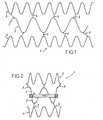
- Figures 1 to 4represent a tubular support 1 for the introduction, percutaneously, of a replacement heart valve 2.
- the structure of the support 1comprises a medial portion 3 comprising the valve 2, two end portions 4 wedging and 5 connecting son of these portions 3 and 4.
- the middle portion 3further comprises a peripheral band 6 provided with the needles d anchoring 7 and a bandage 8 of compressible material.
- the portions 3 and 4are each formed by a corrugated yarn, and the son 5 pointly connect the ends of the corrugations of the portion 3 at the end of an adjacent corrugation of a portion 4.
- the portions 4, seen in developmenthave lengths greater than the length of the portion 3, so that, when the ends of the son respectively forming the portions 3 and 4 are connected to form the tubular structure of the support 1, the diameter of the portion 3 is smaller than the diameter portions 4.
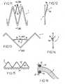
- the diameter of the portion 3is such that this portion 3 can, as shown in FIG. figure 5 , bear against the cardiac ring 10 remaining after removal of the deficient native valve, while the portions 4 can bear against the walls 11 bordering the ring 10.
- These respective diametersare preferably such that said support are made with a slight radial stress of the ring 10 and the walls 11.
- Portion 3has in the expanded state a constant diameter.
- the portions 4may have a constant diameter or a frustoconical shape whose diameter increases as it moves away from the portion 3.
- the entire structure of the support 1is made of a shape memory material, such as a nickel-titanium alloy of the kind called "NITINOL". This material allows this structure to be contracted radially, as shown on the figure 4 at a temperature different from that of the patient's body and to return to the original form shown on the figures 2 and 3 when its temperature approaches or reaches that of the body of the patient.
- the entire structure of the support 1can also be made of a balloon expandable material such as medical stainless steel (316 L steel).
- the valve 2may be of biological or synthetic tissue. It is connected to the portion 3 by sutures or by any other suitable means of attachment. It can also be molded on portion 3.
- Strip 6is in "NITINOL". It is connected to the undulations of the portion 3, halfway up thereof, and has the needles 7 at its zones connected to these undulations.
- the needles 7are constituted by strands of wire sharp at their free ends, and project radially outwardly of the band 6.
- the lattercan take the wavy shape visible on the figure 4 in the contracted state of the support 1 and the circular shape visible on the figure 3 in the expanded state of this support 1.
- the strip 6forms undulations 6a protruding radially on the outside of the support 1, beyond the needles 7, so that these needles 7, in this position of retraction, do not interfere with the introduction of the support 1 in a catheter nor, once the support 1 introduced into the heart with the aid of this catheter, the deployment of this support 1.
- the return of the band 6 in its form circularbrings the needles 7 in a deployed position, allowing them to fit into the ring 10 to complete the anchoring of the support 1.
- the bandage 8is fixed on the band 6. Its compressible material enables it to absorb the surface irregularities that may exist at or near the ring 10 and thus ensure a perfect seal of the valve 2.
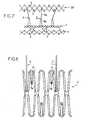
- the figure 6shows a structure of the support 1 comprising a single portion 4, connected to the portion 3 by wires 5.
- This portion 4is formed by two corrugated yarns 14 interconnected by son 15.
- the figure 7shows a structure of the support 1 having a portion 3 and a portion 4 connected by connecting son 5.
- These portions 3 and 4have diamond-shaped mesh structures, these meshes being juxtaposed in the circumferential direction of these portions and being connected to each other at two of their opposite angles in the circumferential direction of the circumference. These portions 3 and 4.
- the son 5are connected to these structures at the junction area of two consecutive meshes. These meshes further comprise anchoring hooks 7 extending through them from one of their angles located in the longitudinal direction of the support 1.
- the figure 8illustrates, on an enlarged scale, the structure of this portion 4 and a portion of the son 5, as cut for example by laser in a stainless steel plate, and after bending of the sharp ends 7a of the hooks 7. These have , seen in profile, a form as shown on the Figures 12 or 14 .
- the structure represented on the figure 7also comprises an axial holding portion 20, having a structure identical to that of the portion 4 but with larger mesh, and three son 5 in length important, connecting this portion 20 to the portion 3.
- These son 5have, on the side of the portion 20, a unitary suture 5a and, on the side of the portion 3, a double structure 5b. Their number corresponds to the three commissures that form the three valves of the valve 2, which facilitates the mounting of the valve 2 on the support 1 and shaped.
- the support according to the figure 7is intended to be used, so this appears on the figure 9 when the body conduit comprising the valve to be replaced, in particular the aorta, has an aneurysm around the valve.
- the length of the son 5 connecting the portions 3 and 20is provided in such a way that, after implantation, the portion 20 is located in an unexpanded zone of said body duct, and this portion 20 is provided so as to bear against the wall of the body. this conduit.
- the figure 10shows a structure similar to the figure 7 but not expanded, and except that the three son 5 have a unitary structure but comprise a corrugated wire 21 providing a complementary support near the portion 3.
- This wire 21is designed to support a valve 2 with three valves.
- each hook 7comprises two branches 7b; each of these branches 7b is connected to the other branch 7b at one end and to a branch of the structure 1 at its other end.
- the junction zone of the two branches 7bhas a bent lug 7a hooking.
- the figure 15shows a portion 3 comprising two corrugated son 25, 26 extending one close to the other and a secondary corrugated wire 27.
- the son 25, 26can be used to achieve the insertion of a valve 2 of biological material between them and the attachment of this valve 2 to them by means of sutures 27.
- the figure 17shows part of the support 1 according to the Figures 1 to 5 and how the compressible material constituting the bandage 8 can absorb the surface irregularities that may exist at or near the ring 10, which result from calcifications.
- the figure 18shows a support 1 whose band 6 is devoid of compressible bandage. A material can then be applied, by means of a suitable cannula (not shown), between the ring 10 and this strip 6, this material being able to freeze within a specified time after this application.
- the figure 19shows a support 1 whose band 6 has a broken line section, defining, on the radially outer side, a lower shoulder.
- a peripheral band 8inflatable by means of a catheter (not shown).
- This band 8delimits a chamber and has a radially expandable structure, such that it has in cross section, in the inflated state, two enlarged ends projecting on either side of the strip 6.
- This chambercan receive a fluid inflation to freeze within a specified time after introduction into said chamber. Once this material is frozen, the inflation catheter is cut.
- FIGS. 20 and 21show a support 1 whose band 6 receives an inflatable insert 8 having a diabolo cross-section in the inflated state, this insert 8 being able to be inflated by means of a catheter 29.
- the insert 8is put in place at the deflated state ( figure 20 ) at the locations in which there is a space between the band 6 and the remaining cardiac ring 10. Its diabolo shape allows this insert 8 (cf. figure 21 ) to best conform to adjacent irregular structures and to ensure a better seal.
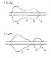
- the figure 22shows a balloon 30 for deploying the support 1 according to the Figures 7 to 9 .
- This balloon 30comprises a cylindrical portion 31 whose diameter in the inflated state allows the expansion of the holding portion 20, a cylindrical portion 32 of smaller diameter, adapted to carry out the expansion of the portion 3, and a frustoconical portion. 33, allowing the expansion of the portion 4.
- the portion 32may be limited to what is strictly necessary to deploy the portion 3, which makes it possible to produce the balloon 30 in two parts instead of one, thus limiting the volume of this balloon 30.
- the figure 24shows a support 1 whose middle portion 3 is in two parts 3a, 3b.
- Part 3ais made of wavy wave wire, to support the valve 2, and the portion 3b, adjacent to said portion 3a and connected thereto by bridges 35 is wave-corrugated wire.
- This part 3bby its structure, has a relatively large radial expansion force elevated and is intended to be placed opposite the ring 10 in order to repel native leaflets voluntarily calcified, thickened and indurated, or remnants of valvular leaflets after valve resection against or in the wall of the duct.
- This axial portion 3a, 3bthus eliminates the discomfort induced by these leaflets or leaflet residues at the time of installation of the valve 2.
- the inventionprovides a tubular support for the introduction, percutaneously, of a replacement heart valve providing, thanks to its portions 3 and 4, a perfect certainty of holding in position after implantation.
- This supportalso allows a perfect seal of the replacement valve, even in the case of a cardiac ring having a more or less irregular surface and / or more or less calcified, and its position can be adapted and / or corrected if necessary to moment of implantation.
Landscapes
- Health & Medical Sciences (AREA)
- Cardiology (AREA)
- Engineering & Computer Science (AREA)
- Biomedical Technology (AREA)
- Life Sciences & Earth Sciences (AREA)
- Public Health (AREA)
- Heart & Thoracic Surgery (AREA)
- Vascular Medicine (AREA)
- Oral & Maxillofacial Surgery (AREA)
- Animal Behavior & Ethology (AREA)
- General Health & Medical Sciences (AREA)
- Transplantation (AREA)
- Veterinary Medicine (AREA)
- Mechanical Engineering (AREA)
- Prostheses (AREA)
- Medicinal Preparation (AREA)
- Containers And Packaging Bodies Having A Special Means To Remove Contents (AREA)
- Sheet Holders (AREA)
- Infusion, Injection, And Reservoir Apparatuses (AREA)
Abstract
Description
Translated fromFrenchLa présente invention concerne un support tubulaire de mise en place, par voie percutanée, d'une valve cardiaque de remplacement. Elle concerne également un instrument de mise en place de ce support.The present invention relates to a tubular support for the introduction, percutaneously, of a replacement heart valve. It also relates to an instrument for setting up this medium.
La technique classique de remplacement d'une valve cardiaque consiste à opérer à coeur ouvert. Cette technique oblige à une anesthésie générale, à un large abord, et à un arrêt du coeur impliquant la mise du patient sous circulation extracorporelle. Elle est donc particulièrement lourde à mettre en oeuvre et induit des risques opératoires importants pour le patient.The classic technique of replacing a heart valve is to operate with an open heart. This technique requires a general anesthesia, at a wide angle, and a heart failure involving the placing of the patient under extracorporeal circulation. It is therefore particularly heavy to implement and induces significant operational risks for the patient.
Pour remédier à cet inconvénient, il a été envisagé d'opérer l'ablation d'une valve cardiaque déficiente par voie percutanée, avec un abord vasculaire périphérique. La demande de brevet n°
En ce qui concerne la mise en place d'une valve cardiaque de remplacement, il a été envisagé de fixer cette valve sur un support présentant une structure en fil ou en réseau de fils, couramment dénommé "stent". Ce support peut être contracté radialement pour pouvoir être introduit dans le corps du patient par voie percutanée, au moyen d'un cathéter, et peut être déployé radialement une fois positionné au niveau du site à équiper de la valve pour assurer ainsi le montage de cette valve. Le brevet n°
Les systèmes de "stent" envisagés à ce jour pour la mise en place d'une valve cardiaque enduisent des incertitudes plus ou moins importantes en ce qui concerne leur maintien en position dans les sites à traiter. En particulier, la forme des stents connus n'apparaît pas adaptée à celle de ces sites, dans lesquels la paroi cardiaque s'évase de part et d'autre de l'anneau cardiaque.The "stent" systems envisaged to date for the implementation of a heart valve cover uncertainties more or less important with respect to their holding in position in the sites to be treated. In particular, the shape of the known stents does not appear to be adapted to that of these sites, in which the cardiac wall flares on either side of the cardiac ring.
En outre, l'anneau cardiaque subsistant après ablation de la valve native peut gêner la mise en place de ces stents.In addition, the cardiac ring remaining after removal of the native valve may interfere with the placement of these stents.
Ces systèmes connus induisent également, dans certains cas, des problèmes d'étanchéité de la valve de remplacement. En effet, ledit anneau cardiaque subsistant peut présenter une surface plus ou moins irrégulière et plus ou moins calcifiée, qui non seulement amoindrit la qualité de l'appui du stent contre cet anneau mais également peut être à l'origine de fuites entre la valve et cet anneau.These known systems also induce, in some cases, sealing problems of the replacement valve. Indeed, said remaining cardiac ring may have a more or less irregular and more or less calcified surface, which not only reduces the quality of the support of the stent against this ring but also may cause leaks between the valve and this ring.
Certains matériels existants présentent par ailleurs des inconvénients en ce qui concerne leur implantation proprement dite. En particulier, ces matériels ne peuvent plus guère être déplacés après déploiement du support même si leur position n'est pas optimale.Some existing materials also have disadvantages with respect to their actual implementation. In particular, these materials can hardly be moved after deployment of the support even if their position is not optimal.
La présente invention vise à remédier à ces inconvénients importants.The present invention aims to remedy these significant disadvantages.
Son objectif principal est de fournir un support ("stent") procurant une meilleure certitude de maintien en position après implantation.Its main purpose is to provide a support ("stent") providing better certainty of maintaining position after implantation.
Un autre objectif de l'Invention est de fournir un support permettant d'éliminer la gêne qu'induisent, au moment de la mise en place de la valve de remplacement, les feuillets valvulaires natifs volontiers calcifiés, épaissis et indurés, ou les restes des feuillets valvulaires après résection valvulaire.Another object of the invention is to provide a support to eliminate the discomfort induced by the introduction of the replacement valve, the native valve leaflets voluntarily calcified, thickened and indurated, or the remains of the valvular leaflets after valve resection.
Un autre objectif encore de l'invention est de fournir un support permettant une parfaite étanchéité de la valve de remplacement, même en cas d'un anneau cardiaque subsistant qui présente une surface plus ou moins irrégulière et/ou plus ou moins calcifiée. Le document
L'invention a également pour objectif de fournir un support dont la position puisse être adaptée et/ou corrigée le cas échéant au moment de l'implantation.The invention also aims to provide a support whose position can be adapted and / or corrected if necessary at the time of implantation.
Le support concerné comprend, de manière connue en soi, une structure en fil ou en réseau de fils susceptible d'être contractée radialement pour permettre l'introduction de l'ensemble support-valve dans le corps du patient, au moyen d'un cathéter, et d'être déployée pour permettre la prise d'appui de cette structure contre la paroi du site à équiper de la valve.The support concerned comprises, in a manner known per se, a son or wire network structure capable of being contracted radially to allow the introduction of the support-valve assembly into the body of the patient, by means of a catheter and to be deployed to allow the support of this structure against the wall of the site to be equipped with the valve.
Selon l'invention, cette structure comprend :
- une portion axiale de support de valve, présentant une structure en fil ou en réseau de fils propre à recevoir la valve de remplacement montée sur elle, et propre à prendre appui contre l'anneau cardiaque;
- au moins une portion axiale de calage, présentant une structure en fil ou en réseau de fils distincte de la structure de ladite portion axiale de support de valve, et dont au moins une partie présente, à l'état déployé, un diamètre supérieur au diamètre à l'état déployé de ladite portion axiale de support de valve, tel que cette portion axiale de calage est propre à prendre appui contre la paroi bordant ledit anneau cardiaque; et
- au moins un fil de liaison desdites portions, ce ou ces fils étant reliés ponctuellement à ces portions, de manière à ne pas faire obstacle au déploiement desdites portions axiales selon leurs diamètres respectifs.
- an axial portion of valve support, having a wire structure or network of son adapted to receive the replacement valve mounted on it, and able to bear against the cardiac ring;
- at least one axial wedging portion, having a wire structure or wire network distinct from the structure of said axial valve support portion, and of which at least a portion has, in the deployed state, a diameter greater than the diameter in the deployed state of said axial portion of valve support, such that this axial wedging portion is adapted to bear against the wall bordering said cardiac ring; and
- at least one connecting wire of said portions, this or these son being punctually connected to these portions, so as not to hinder the deployment of said axial portions according to their respective diameters.
L'invention fournit ainsi un support en au moins deux portions axiales individualisées l'une par rapport à l'autre en ce qui concerne leur structure, qui sont reliées de manière localisée par au moins un fil ; ce ou ces fils ne font pas obstacle à un déploiement différent de la portion axiale comportant la valve et de la ou des portions axiales de calage.The invention thus provides a support in at least two individual axial portions with respect to their structure, which are connected in a localized manner by at least one wire; this or these son do not interfere with a different deployment of the axial portion having the valve and the axial portion or wedges.
La présence d'une structure en fil ou en réseau de fils au niveau de la portion axiale de support de valve permet un parfait assemblage de cette valve à cette structure, et la forme ainsi que le diamètre de cette portion axiale peuvent être adaptés à une prise d'appui dans les meilleures conditions contre l'anneau cardiaque subsistant. En particulier, cette portion axiale de support de valve peut présenter une force d'expansion radiale telle qu'elle repousse ("impacte") les feuillets valvulaires volontiers calcifiés, ou les restes des feuillets valvulaires après résection valvulaire sur ou dans les tissus sous-jacents, de sorte que ces éléments ne constituent pas une gêne à la mise en place de la valve de remplacement. Cette structure permet également de supporter d'éventuels moyens d'ancrage du support et/ou d'éventuels moyens d'étanchéité de l'espace existant entre l'anneau cardiaque subsistant et la valve de remplacement, comme indiqué plus loin.The presence of a wire structure or wire network at the axial portion of valve support allows a perfect assembly of this valve to this structure, and the shape and the diameter of this axial portion can be adapted to a support under the best conditions against the remaining cardiac ring. In particular, this axial portion of valve support may have a radial expansion force such as it pushes ("impact") valvular sheets voluntarily calcified, or remnants of valvular leaflets after valve resection on or in the subclinical tissues. These elements do not interfere with the installation of the replacement valve. This structure also makes it possible to support any means of anchoring the support and / or any sealing means of the space existing between the remaining cardiac ring and the replacement valve, as indicated below.
La forme et/ou le diamètre de chaque portion axiale de calage peuvent être adaptés à une prise d'appui dans les meilleures conditions contre la paroi cardiaque située aux abords de l'anneau cardiaque subsistant. Notamment, cette portion axiale de calage peut présenter une forme tubulaire de diamètre constant supérieur à celui de la portion axiale de support de valve, ou une forme tronconique dont le diamètre va en augmentant en s'éloignant de la portion axiale de support de valve.The shape and / or the diameter of each axial portion of wedging can be adapted to a bearing under the best conditions against the cardiac wall located near the remaining cardiac ring. In particular, this axial wedging portion may have a tubular shape of constant diameter greater than that of the axial portion of the valve support, or a frustoconical shape whose diameter increases as it moves away from the axial portion of the valve support.
De préférence, le support tubulaire présente une portion axiale de support de valve en au moins deux parties, dont au moins une est adaptée à supporter la valve et dont au moins une autre est adaptée à repousser les feuillets valvulaires natifs ou les restes des feuillets valvulaires natifs après résection valvulaire, dans ou sur le tissu adjacent afin de rendre cette zone apte à recevoir le support tubulaire.Preferably, the tubular support has an axial portion of valve support in at least two parts, at least one of which is adapted to support the valve and at least one other is adapted to push the native leaflets or the remains of the leaflets native valves after valve resection, in or on the adjacent tissue to make this area suitable for receiving the tubular support.
Cette portion axiale de support de valve élimine la gêne qu'induisent ces éléments valvulaires ou annulaires cardiaques au moment de la mise en place de la valve de remplacement. La force radiale de cette portion axiale de support de valve assure en effet, en impactant tout ou partie du tissu valvulaire dans ou au voisinage de la paroi, une surface plus régulière et plus apte à recevoir l'axe de support de valve. Elle assure également une meilleure solidarisation avec la paroi tout en réduisant le risque de fuite para prothétique.This axial portion of valve support eliminates the discomfort that induce these valvular elements or cardiac annular at the time of installation of the replacement valve. The radial force of this axial portion of valve support ensures indeed, by impacting all or part of the valve tissue in or near the wall, a more even surface and more adapted to receive the valve support shaft. It also ensures better bonding with the wall while reducing the risk of para-prosthetic leakage.
La portion axiale de support de valve peut notamment comprendre une partie en fil ondulé à larges ondes, pour supporter la valve, et une partie en fil ondulé à ondes réduites, adjacente à ladite partie à larges ondes, présentant une force radiale relativement importante pour permettre de repousser ledit tissu valvulaire contre ou dans la paroi du conduit.The axial portion of the valve support may in particular comprise a portion of corrugated wire with large waves, to support the valve, and a portion of reduced wave corrugated wire, adjacent to said broad wave portion, having a relatively large radial force to allow pushing said valvular tissue against or in the wall of the conduit.
De préférence, le support selon l'invention présente deux portions axiales de calage, l'une étant reliée à une extrémité axiale de ladite portion de support de valve et l'autre à l'autre extrémité axiale de cette même portion de support de valve.Preferably, the support according to the invention has two axial wedging portions, one being connected to one axial end of said valve support portion and the other to the other axial end of said same valve support portion. .
Ces deux portions axiales de calage permettent ainsi un calage du support de part et d'autre de l'anneau cardiaque subsistant, et permettent par conséquent un parfait calage du support dans deux directions opposées par rapport au site traité.These two axial wedging portions thus allow a wedging of the support on either side of the remaining cardiac ring, and therefore allow a perfect wedging of the support in two opposite directions with respect to the treated site.
Si nécessaire, par exemple dans le cas où le conduit comprenant la valve présenterait un anévrisme, le support selon l'invention comprend :
- une portion axiale de maintien, propre à prendre appui à l'état déployé contre la paroi du conduit, et
- des fils de liaison tels que précités, reliant ladite portion axiale de support de valve et ladite portion axiale de maintien, ces fils ayant une longueur telle que la portion axiale de maintien soit située après implantation à distance de la portion axiale de support de valve.
- an axial portion of support, able to bear in the deployed state against the wall of the conduit, and
- connecting son as mentioned above, connecting said axial portion of valve support and said axial holding portion, these son having a length such that the axial portion of maintenance is located after remote implantation of the axial portion of the valve support.
Cette distance permet à ladite portion axiale de maintien de prendre appui contre une zone de la paroi du conduit non concernée par une éventuelle affection pouvant exister aux abords de la valve, en particulier un anévrisme. La longueur des fils de liaison peut également être calculée afin d'éviter que la portion axiale de maintien soit au contact des ostia des artères coronaires.This distance allows said axial portion of support to bear against an area of the duct wall not concerned by any possible condition that may exist around the valve, in particular an aneurysm. The length of the connecting wires can also be calculated to prevent the axial portion of maintenance is in contact with ostia coronary arteries.
Les portions axiales précitées (de support de valve, de calage, de maintien) peuvent présenter une structure en fil ondulé, en zig-zag ou, de préférence, une structure en mailles avant une forme de losange, les mailles étant juxtaposées dans le sens de la circonférence de ces portions.The aforementioned axial portions (valve support, wedging, holding) may have a corrugated wire structure, zig-zag or, preferably, a mesh structure before a diamond shape, the meshes being juxtaposed in the direction of the circumference of these portions.
Cette dernière structure permet une force radiale adaptée, permettant d'assurer une parfaite prise d'appui dedites portions contre la paroi qui les reçoit.This latter structure allows a radial force adapted to ensure a perfect support of said portions against the wall that receives them.
Le support selon l'invention peut être réalisé en un métal plastiquement déformable. L'instrument de mise en place du support comprend alors un ballonnet présentant une portion axiale d'un diamètre prédéterminé, adaptée à réaliser le déploiement de ladite portion axiale de support de valve, et au moins une portion axiale conformée pour présenter, à l'état gonflé, une section supérieure à celle du conduit à traiter, de manière à réaliser le déploiement de la portion axiale de calage placée sur elle jusqu'à ce que cette portion axiale de calage rencontre la paroi contre laquelle elle doit venir en appui.The support according to the invention may be made of a plastically deformable metal. The support placement instrument then comprises a balloon having an axial portion of a predetermined diameter, adapted to carry out the deployment of said axial portion of valve support, and at least one axial portion shaped to present, to the inflated state, a section greater than that of the duct to be treated, so as to achieve the deployment of the axial wedging portion placed on it until this axial wedging portion meets the wall against which it must come to bear.
Le support selon l'invention peut également être réalisé en un matériau à mémoire de forme, tel qu'un alliage nickel-titane du genre dénommé "NITINOL", pouvant être contracté radialement à une température différente de celle du corps du patient et retrouvant une forme originelle lorsque sa température approche ou atteint celle du corps du patient.The support according to the invention can also be made of a shape memory material, such as a nickel-titanium alloy of the kind called "NITINOL", which can be contracted radially at a temperature different from that of the body of the patient and found again. original form when its temperature approaches or reaches that of the body of the patient.
Selon une autre possibilité, le support est réalisé en un matériau à mémoire de forme mais susceptible de déformation plastique, ou comprend des parties en un matériau à mémoire de forme et des parties en un matériau susceptible de déformation plastique, et est conformé de manière telle qu'il puisse être amené, par mémoire de forme ou par déformation plastique, d'un état de contraction à un état de déploiement intermédiaire stable entre l'état de contraction et l'état de déploiement total, puis, par déformation plastique ou par mémoire de forme respectivement, dudit état de déploiement intermédiaire audit état de déploiement total ; dans ledit état de déploiement intermédiaire, le support présente des dimensions telles qu'il reste mobile par rapport au site à traiter.According to another possibility, the support is made of a shape memory material but capable of plastic deformation, or comprises parts of a shape memory material and parts made of a material capable of plastic deformation, and is shaped in such a way it can be brought, by shape memory or by plastic deformation, from a state of contraction to a state of stable intermediate deployment between the state of contraction and the state of total deployment, then, by plastic deformation or by shape memory respectively, from said intermediate deployment state to said full deployment state; in said intermediate deployment state, the support has dimensions such that it remains mobile with respect to the site to be treated.
Le support est ainsi amené au niveau du site à traiter puis est déployé dans ledit état intermédiaire ; sa position peut alors éventuellement être adaptée et/ou corrigée puis le support est amené dans son état de déploiement total.The support is thus brought to the site to be treated and then deployed in said intermediate state; its position may then be adapted and / or corrected and the support is brought into its total deployment state.
Le matériau à mémoire de forme mais susceptible de déformation plastique précité peut notamment être un alliage nickel-titane du genre dénommé "NITINOL martensitique", susceptible d'être déformé plastiquement au moyen d'un ballonnet.The shape memory material but capable of plastic deformation supra may in particular be a nickel-titanium alloy of the kind called "martensitic NITINOL", capable of being deformed plastically by means of a balloon.
Avantageusement, le support selon l'invention comprend des moyens d'ancrage propres à s'insérer dans la paroi du site à traiter, conformés de manière à être mobiles entre une position inactive, dans laquelle ils ne font pas obstacle à l'introduction du support dans le corps du patient, et une position active, dans laquelle ils s'insèrent dans la paroi du site à traiter.Advantageously, the support according to the invention comprises anchoring means adapted to be inserted into the wall of the site to be treated, shaped so as to be movable between an inactive position, in which they do not prevent the introduction of the support in the patient's body, and an active position, into which they fit into the wall of the site to be treated.
Une parfaite immobilisation du support au niveau du site est ainsi obtenue.A perfect immobilization of the support at the level of the site is thus obtained.
En particulier, ces moyens d'ancrage peuvent présenter la forme d'aiguilles et peuvent être montés sur le support entre des positions de rétractation radiale et des positions de saillie radiale.In particular, these anchoring means can have the shape of needles and can be mounted on the support between radial retraction positions and radial projection positions.
Avantageusement, la portion axiale de support de valve comporte, au niveau de sa face extérieure, un moyen d'étanchéité conformé de manière à absorber les irrégularités de surface pouvant exister au niveau ou à proximité de l'anneau cardiaque subsistant.Advantageously, the axial portion of the valve support comprises, at its outer face, a sealing means shaped so as to absorb the surface irregularities that may exist at or near the remaining cardiac ring.
Ce moyen d'étanchéité peut être constitué par une bande périphérique en un matériau compressible ou par une bande périphérique délimitant une chambre et ayant une structure radialement expansible, cette chambre pouvant recevoir un fluide de gonflage propre à se figer dans un délai déterminé après introduction dans ladite chambre. Ce moyen d'étanchéité peut également comprendre un matériau pouvant être appliqué entre l'anneau cardiaque subsistant et la portion axiale de support de valve, ce matériau étant propre à se figer dans un délai déterminé après cette application. Dans ce cas, ce matériau peut notamment être thermoactivable, par exemple au moyen d'un laser, à travers le ballonnet, ou activable par émission de lumière d'une fréquence déterminée, par exemple au moyen d'un laser à ultra-violets, à travers le ballonnet. Ledit moyen d'étanchéité peut également se présenter sous forme d'un insert gonflable ayant une section transversale en diabolo à l'état gonflé, pouvant être inséré entre l'anneau cardiaque subsistant et la portion axiale de support de valve. Ladite forme en diabolo permet à cet insert de se conformer au mieux aux structures irrégulières adjacentes et d'assurer une meilleure étanchéité.This sealing means may consist of a peripheral band made of a compressible material or of a peripheral band delimiting a chamber and having a radially expandable structure, this chamber being able to receive an inflation fluid capable of freezing within a predetermined time after introduction into said chamber. This sealing means may also comprise a material that can be applied between the remaining cardiac ring and the axial portion of the valve support, this material being able to freeze within a predetermined time after this application. In this case, this material may in particular be thermoactivatable, for example by means of a laser, through the balloon, or activatable by light emission of a determined frequency, for example by means of an ultraviolet laser, through the balloon. Said sealing means may also be in the form of an insert inflatable having a diabolo-shaped cross section in the inflated state, insertable between the remaining cardiac ring and the axial valve support portion. Said diabolo shape allows this insert to conform best to adjacent irregular structures and to ensure a better seal.
Pour sa bonne compréhension, l'invention est à nouveau décrite ci-dessous en référence au dessin schématique annexé représentant, à titre d'exemples non limitatifs, plusieurs formes de réalisation possibles du support tubulaire qu'elle concerne.
- La
figure 1 est une vue en développé de la structure de ce support, selon une première forme de réalisation ; - la
figure 2 est une vue en coupe du support à l'état déployé, avec la valve cardiaque qu'il comporte ; - la
figure 3 est une vue en bout de ce support à l'état déployé ; - la
figure 4 est une vue en bout de ce support à l'état contracté ; - la
figure 5 est une vue d'un coeur en coupe partielle, sur lequel une valve cardiaque de remplacement a été mise en place au moyen du support selon l'invention ; - la
figure 6 est une vue en développé de la structure du support selon une deuxième forme de réalisation ; - la
figure 7 est une vue en développé de la structure du support selon une troisième forme de réalisation ; - la
figure 8 est une vue de détail d'une partie de cette structure, à échelle agrandie ; - la
figure 9 est une vue du support selon lafigure 7 , après mise en place dans un conduit corporel présentant un anévrisme ; - la
figure 10 est une vue en développé de la structure du support selon une quatrième forme de réalisation ; - la
figure 11 est une vue de détail d'une variante de réalisation d'un crochet d'ancrage que comprend le support selon la quatrième forme de réalisation ; - la
figure 12 est une vue du même détail, en coupe selon la ligne XII-XII de lafigure 11 ; - la
figure 13 est une vue similaire à lafigure 11 , la structure étant dans un état expansé ; - la
figure 14 est une vue similaire à lafigure 12 , la structure étant dans ce même état expansé ; - la
figure 15 est une vue partielle d'une portion de structure du support selon une cinquième forme de réalisation ; - la
figure 16 est une vue agrandie d'une zone de montage d'une valve prothétique sur cette portion ; - la
figure 17 est une vue partielle, en coupe longitudinale, du support selon la première forme de réalisation et d'un anneau cardiaque calcifié ; - la
figure 18 est une vue similaire à lafigure 17 , selon une variante ; - la
figure 19 est une vue similaire à lafigure 17 , selon une autre variante ; - les
figures 20 et 21 sont des vues similaires à lafigure 17 , selon encore une autre variante, dans deux phases de mise en place du support ; - la
figure 22 est une vue en coupe longitudinale d'un ballonnet permettant l'expansion de la structure du support représenté auxfigures 7 à 9 ; - la
figure 23 est une vue en coupe longitudinale d'un ballonnet selon une variante de réalisation, et - la
figure 24 est une vue similaire à lafigure 5 , montrant un coeur sur lequel une valve cardiaque de remplacement a été mise en place au moyen du support selon l'invention, selon une sixième forme de réalisation.
- The
figure 1 is a developed view of the structure of this support, according to a first embodiment; - the
figure 2 is a sectional view of the support in the deployed state, with the heart valve that it comprises; - the
figure 3 is an end view of this support in the deployed state; - the
figure 4 is an end view of this support in the contracted state; - the
figure 5 is a view of a heart in partial section, on which a replacement heart valve has been put in place by means of the support according to the invention; - the
figure 6 is a developed view of the support structure according to a second embodiment; - the
figure 7 is a developed view of the support structure according to a third embodiment; - the
figure 8 is a detail view of a portion of this structure, on an enlarged scale; - the
figure 9 is a view of the support according to thefigure 7 after placement in a bodily canal with aneurysm; - the
figure 10 is a developed view of the support structure according to a fourth embodiment; - the
figure 11 is a detail view of an alternative embodiment of an anchor hook that comprises the support according to the fourth embodiment; - the
figure 12 is a view of the same detail, in section along the line XII-XII of thefigure 11 ; - the
figure 13 is a view similar to thefigure 11 the structure being in an expanded state; - the
figure 14 is a view similar to thefigure 12 the structure being in this same expanded state; - the
figure 15 is a partial view of a structural portion of the support according to a fifth embodiment; - the
figure 16 is an enlarged view of a mounting area of a prosthetic valve on this portion; - the
figure 17 is a partial view, in longitudinal section, of the support according to the first embodiment and a calcified cardiac ring; - the
figure 18 is a view similar to thefigure 17 according to a variant; - the
figure 19 is a view similar to thefigure 17 according to another variant; - the
Figures 20 and 21 are views similar to thefigure 17 , according to yet another variant, in two phases of setting up the support; - the
figure 22 is a longitudinal sectional view of a balloon allowing the expansion of the support structure shown in FIGS.Figures 7 to 9 ; - the
figure 23 is a longitudinal sectional view of a balloon according to an alternative embodiment, and - the
figure 24 is a view similar to thefigure 5 , showing a heart on which a replacement heart valve has been put in place by means of the support according to the invention, according to a sixth embodiment.
Par simplification, les parties ou éléments de ces différentes formes de réalisation qui sont identiques ou similaires d'une forme de réalisation à une autre sont définis par les mêmes références numériques.Les
La structure du support 1 comprend une portion médiane 3 comportant la valve 2, deux portions extrémales 4 de calage et des fils 5 de liaison de ces portions 3 et 4. La portion médiane 3 comporte en outre une bande périphérique 6 pourvue d'aiguilles d'ancrage 7 et d'un bandage 8 en matériau compressible.The structure of the
Ainsi que cela apparaît plus particulièrement sur la
Le diamètre de la portion 3 est tel que cette portion 3 peut, comme le montre la
La portion 3 présente à l'état déployé un diamètre constant. Les portions 4 peuvent présenter un diamètre constant ou une forme tronconique dont le diamètre va en augmentant en s'éloignant de la portion 3.
L'ensemble de la structure du support 1 est réalisé en un matériau à mémoire de forme, tel qu'un alliage nickel-titane du genre dénommé "NITINOL". Ce matériau permet à cette structure d'être contractée radialement, comme montré sur la
La valve 2 peut être en tissu biologique ou synthétique. Elle est reliée à la portion 3 par des sutures ou par tous autres moyens de fixation appropriés. Elle peut également être moulée sur la portion 3.The valve 2 may be of biological or synthetic tissue. It is connected to the
La bande 6 est en "NITINOL". Elle est reliée aux ondulations de la portion 3, à mi-hauteur de celles-ci, et comporte les aiguilles 7 au niveau de ses zones reliées à ces ondulations.
Les aiguilles 7 sont constituées par des brins de fil métallique acérés à leurs extrémités libres, et font saillie radialement vers l'extérieur de la bande 6.The
Cette dernière peut prendre la forme ondulée visible sur la
Le bandage 8 est fixé sur la bande 6. Son matériau compressible lui permet d'absorber les irrégularités de surface pouvant exister au niveau ou à proximité de l'anneau 10 et d'assurer ainsi une parfaite étanchéité de la valve 2.The
La
La
Ces portions 3 et 4 ont des structures à mailles en forme de losange, ces mailles étant juxtaposées dans le sens de la circonférence de ces portions et étant reliées les unes aux autres au niveau de deux de leurs angles opposés dans le sens de la circonférence de ces portions 3 et 4. Les fils 5 sont reliés à ces structures au niveau de la zone de jonction de deux mailles consécutives. Ces mailles comportent en outre des crochets d'ancrage 7 s'étendant à travers elles à partir de l'un de leurs angles situés dans le sens longitudinal du support 1.These
La
La structure représentée sur la
Le support selon la
La
Les
La
La
La
La
Les
La
Ainsi que montre la
La
Cette portion axiale 3a, 3b élimine ainsi la gêne qu'induisent ces feuillets ou résidus de feuillets au moment de la mise en place de la valve 2.This
Il apparaît de ce qui précède que l'invention fournit un support tubulaire de mise en place, par voie percutanée, d'une valve cardiaque de remplacement procurant, grâce à ses portions 3 et 4, une parfaite certitude de maintien en position après implantation. Ce support permet également une parfaite étanchéité de la valve de remplacement, même en cas d'un anneau cardiaque présentant une surface plus ou moins irrégulière et/ou plus ou moins calcifiée, et sa position peut être adaptée et/ou corrigée le cas échéant au moment de l'implantation.It appears from the foregoing that the invention provides a tubular support for the introduction, percutaneously, of a replacement heart valve providing, thanks to its
Il va de soi que l'invention n'est pas limitée à la forme de réalisation décrite ci-dessus à titre d'exemple mais qu'elle en embrasse au contraire toutes les variantes de réalisation couvertes par les revendications ci-annexées.It goes without saying that the invention is not limited to the embodiment described above by way of example but that it encompasses all the variants covered by the appended claims.
Claims (17)
- A tubular support for positioning, by percutaneous route, of replacement heart valve (2), which has a structure in the form of a wire or in the form of a network of wires which can be contracted radially in order to make possible the introduction of the assembly comprising support (1) and valve (2) into the body of the patient by means of a catheter, and which can be deployed in order to allow this structure to support the wall of the site which is to be equipped with valve (2), this support (1) comprising- an axial portion (3) for supporting the valve (2), which has a structure in the form of a wire or in the form of a network of wires suitable for receiving replacement valve (2) mounted thereon, and suitable for bearing against the cardiac ring (10);- at least one other axial portion (4), which has a structure in the form of a wire or in the form of a network of wires which is distinct from the structure of said axial portion (3) for supporting the valve;characterized by the fact that- said at least one other axial is an axial wedging portion (4) which is distinct from the structure of said axial portion (3) for supporting the valve, at least a part of this axial wedging portion (4) having, in the deployed state, a diameter greater than the diameter in the deployed state of said axial portion (3) for supporting the valve, such that this axial wedging portion (4) is suitable for supporting the wall bordering said cardiac ring (10); and- the tubular support comprises at least one wire (5) for connecting said portions (3, 4), this wire or these wires (5) being connected at points to these portions (3, 4), in such a way as not to obstruct the deployment of said axial portions (3, 4) according to their respective diameters.
- The tubular support according to claim 1,characterized by the fact that it comprises an axial portion (3) for supporting the valve in the form of at least two parts (3a, 3b), of which at least one is suitable for supporting the valve (2) and of which at least another is suitable for pushing back the native valve sheets or the residues of the native valve sheets after valve resection, into or onto the adjacent tissue in order to make this region able to receive the tubular support.
- The tubular support according to claim 1 or 2,characterized by the fact that at least one axial wedging portion (4) has a tubular form of constant diameter greater than that of axial portion (3) for supporting the valve.
- The tubular support according to claim 1 or 2,characterized by the fact that at least one axial wedging portion (4) has the form of a truncated cone whose diameter increases away from axial portion (3) for supporting the valve.
- The tubular support according to one of Claims 1 to 4,characterized by the fact that it comprises:- an axial holding portion (20), suitable for supporting in the deployed state against the wall of the passage containing the valve, and- connecting wires (5), connecting said axial portion (3) for supporting the valve and said axial holding portion (20), these wires (5) having a length such that axial holding portion (20) is situated after implantation a distance away from axial portion (3) for supporting the valve.
- The tubular support according to one of Claims 1 to 5,characterized by the fact that each axial portion (3) for supporting the valve, axial wedging portion (4) or axial holding portion (20) has a structure in diamond-shaped mesh form, the mesh parts being juxtaposed in the direction of the circumference of this portion (3, 4, 20).
- The tubular support according to one of Claims 1 to 6,characterized by the fact that it has two axial wedging portions (4), one connected to an axial end of said portion (3) for supporting the valve and the other to the other axial end of this same valve support portion (3).
- The tubular support according to one of Claims 1 to 7,characterized by the fact that it is made from a plastically deformable metal.
- The tubular support according to one of Claims 1 to 7,characterized by the fact that it is made from a metal with shape memory, such as the nickel-titanium alloy known as "Nitinol," which can be contracted radially at a temperature different from that of the body of the patient and which regains its original shape when its temperature approaches or reaches that of the body of the patient.
- The tubular support according to one of Claims 1 to 7,characterized by the fact that it is made from a metal with a shape memory but that is plastically deformable, or has parts made from a material with shape memory and parts made from a material that can be plastically deformed, and by the fact that it is shaped in such a way that it can be brought, by shape memory or plastic deformation, from a state of contraction to a stable intermediate state of deployment between the state of contraction and the state of total deployment, and then by plastic deformation or shape memory, as the case may be, from said intermediate state of deployment to said state of total deployment; in said intermediate state of deployment, the support has dimensions such that it remains mobile with respect to the site to be treated.
- The tubular support according to one of Claims 1 to 10,characterized by the fact that it has some anchoring means (7) suitable for being inserted into the wall of the site to be treated, formed in such a way as to be movable between an inactive position, in which it does not obstruct the introduction of support (1) into the body of the patient, and an active position, in which it is inserted in the wall of the site to be treated.
- The tubular support according to one of Claims 1 to 11,characterized by the fact that said axial portion (3) for supporting the valve, at its exterior surface, sealing means (8) formed in such a way as to absorb the surface irregularities which might exist at or near the cardiac ring (10).
- The tubular support according to claim 12,characterized by the fact that sealing means (8) includes a peripheral shell made of a compressible material.
- The tubular support according to claim 12,characterized by the fact that sealing means (8) includes a peripheral shell delimiting a chamber and having a radially expandable structure, this chamber being capable of receiving an inflating fluid suitable for solidification after a predetermined period of time following introduction into said chamber.
- The tubular support according to claim 12,characterized by the fact that sealing means (8) includes a material that can be applied between cardiac ring (10) and axial portion (3) for supporting the valve, this material being suitable for solidification after a predetermined delay following application.
- The tubular support according to claim 12,characterized by the fact that sealing means (8) is present in the form of an inflatable insert with a spool-shaped cross section in the inflated state, which can be inserted between the cardiac ring (10) and axial portion (3) for supporting the valve.
- The instrument for positioning of the support according to one of claim 8 or 10 to 16,characterized by the fact that it includes balloon (30) which has axial portion (32) with a predetermined diameter, suitable for executing the deployment of said axial support portion of the valve, and at least one axial portion (31, 33) shaped in order to have, in the inflated state, a cross section greater than that of the passage to be treated, so as to execute the deployment of the axial wedging portion placed on it until this axial wedging portion encounters the wall it is intended to support.
Applications Claiming Priority (3)
| Application Number | Priority Date | Filing Date | Title |
|---|---|---|---|
| FR0014028 | 2000-10-31 | ||
| FR0014028AFR2815844B1 (en) | 2000-10-31 | 2000-10-31 | TUBULAR SUPPORT FOR THE PERCUTANEOUS POSITIONING OF A REPLACEMENT HEART VALVE |
| PCT/FR2001/003258WO2002036048A1 (en) | 2000-10-31 | 2001-10-19 | Tubular support for setting, by percutaneous route, a substitution cusp |
Publications (2)
| Publication Number | Publication Date |
|---|---|
| EP1330213A1 EP1330213A1 (en) | 2003-07-30 |
| EP1330213B1true EP1330213B1 (en) | 2009-03-04 |
Family
ID=8855980
Family Applications (1)
| Application Number | Title | Priority Date | Filing Date |
|---|---|---|---|
| EP01980615AExpired - LifetimeEP1330213B1 (en) | 2000-10-31 | 2001-10-19 | Tubular support for setting, by percutaneous route, a substitution heart valve |
Country Status (8)
| Country | Link |
|---|---|
| EP (1) | EP1330213B1 (en) |
| JP (1) | JP4130770B2 (en) |
| AT (1) | ATE424161T1 (en) |
| AU (2) | AU2002212418B2 (en) |
| CA (1) | CA2425342C (en) |
| DE (1) | DE60137863D1 (en) |
| FR (1) | FR2815844B1 (en) |
| WO (1) | WO2002036048A1 (en) |
Cited By (54)
| Publication number | Priority date | Publication date | Assignee | Title |
|---|---|---|---|---|
| US7704222B2 (en) | 1998-09-10 | 2010-04-27 | Jenavalve Technology, Inc. | Methods and conduits for flowing blood from a heart chamber to a blood vessel |
| US7857845B2 (en) | 2005-02-10 | 2010-12-28 | Sorin Biomedica Cardio S.R.L. | Cardiac-valve prosthesis |
| US7896915B2 (en) | 2007-04-13 | 2011-03-01 | Jenavalve Technology, Inc. | Medical device for treating a heart valve insufficiency |
| US8062355B2 (en) | 2005-11-04 | 2011-11-22 | Jenavalve Technology, Inc. | Self-expandable medical instrument for treating defects in a patient's heart |
| US8109996B2 (en) | 2004-03-03 | 2012-02-07 | Sorin Biomedica Cardio, S.R.L. | Minimally-invasive cardiac-valve prosthesis |
| US8206437B2 (en) | 2001-08-03 | 2012-06-26 | Philipp Bonhoeffer | Implant implantation unit and procedure for implanting the unit |
| US8317858B2 (en) | 2008-02-26 | 2012-11-27 | Jenavalve Technology, Inc. | Stent for the positioning and anchoring of a valvular prosthesis in an implantation site in the heart of a patient |
| US8398704B2 (en) | 2008-02-26 | 2013-03-19 | Jenavalve Technology, Inc. | Stent for the positioning and anchoring of a valvular prosthesis in an implantation site in the heart of a patient |
| US8465540B2 (en) | 2008-02-26 | 2013-06-18 | Jenavalve Technology, Inc. | Stent for the positioning and anchoring of a valvular prosthesis |
| US8512397B2 (en) | 2009-04-27 | 2013-08-20 | Sorin Group Italia S.R.L. | Prosthetic vascular conduit |
| US8679174B2 (en) | 2005-01-20 | 2014-03-25 | JenaValve Technology, GmbH | Catheter for the transvascular implantation of prosthetic heart valves |
| US8685084B2 (en) | 2011-12-29 | 2014-04-01 | Sorin Group Italia S.R.L. | Prosthetic vascular conduit and assembly method |
| US8834563B2 (en) | 2008-12-23 | 2014-09-16 | Sorin Group Italia S.R.L. | Expandable prosthetic valve having anchoring appendages |
| US8840661B2 (en) | 2008-05-16 | 2014-09-23 | Sorin Group Italia S.R.L. | Atraumatic prosthetic heart valve prosthesis |
| CN104257442A (en)* | 2014-09-25 | 2015-01-07 | 北京迈迪顶峰医疗科技有限公司 | Intrusive replacement valve and controllable conveying device thereof |
| WO2015055052A1 (en)* | 2013-10-17 | 2015-04-23 | 杭州启明医疗器械有限公司 | Safety improved pulmonary artery stent and pulmonary artery valve replacement apparatus |
| US9044318B2 (en) | 2008-02-26 | 2015-06-02 | Jenavalve Technology Gmbh | Stent for the positioning and anchoring of a valvular prosthesis |
| US9138315B2 (en) | 2007-04-13 | 2015-09-22 | Jenavalve Technology Gmbh | Medical device for treating a heart valve insufficiency or stenosis |
| US9161836B2 (en) | 2011-02-14 | 2015-10-20 | Sorin Group Italia S.R.L. | Sutureless anchoring device for cardiac valve prostheses |
| US9168130B2 (en) | 2008-02-26 | 2015-10-27 | Jenavalve Technology Gmbh | Stent for the positioning and anchoring of a valvular prosthesis in an implantation site in the heart of a patient |
| US9248017B2 (en) | 2010-05-21 | 2016-02-02 | Sorin Group Italia S.R.L. | Support device for valve prostheses and corresponding kit |
| US9289289B2 (en) | 2011-02-14 | 2016-03-22 | Sorin Group Italia S.R.L. | Sutureless anchoring device for cardiac valve prostheses |
| US9848981B2 (en) | 2007-10-12 | 2017-12-26 | Mayo Foundation For Medical Education And Research | Expandable valve prosthesis with sealing mechanism |
| US9974647B2 (en) | 2014-06-12 | 2018-05-22 | Caisson Interventional, LLC | Two stage anchor and mitral valve assembly |
| US10080656B2 (en) | 2012-04-19 | 2018-09-25 | Caisson Interventional Llc | Heart valve assembly systems and methods |
| US10117741B2 (en) | 2013-10-23 | 2018-11-06 | Caisson Interventional, LLC | Methods and systems for heart valve therapy |
| US10265166B2 (en) | 2015-12-30 | 2019-04-23 | Caisson Interventional, LLC | Systems and methods for heart valve therapy |
| US10285810B2 (en) | 2012-04-19 | 2019-05-14 | Caisson Interventional, LLC | Valve replacement systems and methods |
| US10856984B2 (en) | 2017-08-25 | 2020-12-08 | Neovasc Tiara Inc. | Sequentially deployed transcatheter mitral valve prosthesis |
| US10940001B2 (en) | 2012-05-30 | 2021-03-09 | Neovasc Tiara Inc. | Methods and apparatus for loading a prosthesis onto a delivery system |
| US11065138B2 (en) | 2016-05-13 | 2021-07-20 | Jenavalve Technology, Inc. | Heart valve prosthesis delivery system and method for delivery of heart valve prosthesis with introducer sheath and loading system |
| US11154398B2 (en) | 2008-02-26 | 2021-10-26 | JenaValve Technology. Inc. | Stent for the positioning and anchoring of a valvular prosthesis in an implantation site in the heart of a patient |
| US11185405B2 (en) | 2013-08-30 | 2021-11-30 | Jenavalve Technology, Inc. | Radially collapsible frame for a prosthetic valve and method for manufacturing such a frame |
| US11311376B2 (en) | 2019-06-20 | 2022-04-26 | Neovase Tiara Inc. | Low profile prosthetic mitral valve |
| US11337800B2 (en) | 2015-05-01 | 2022-05-24 | Jenavalve Technology, Inc. | Device and method with reduced pacemaker rate in heart valve replacement |
| US11357622B2 (en) | 2016-01-29 | 2022-06-14 | Neovase Tiara Inc. | Prosthetic valve for avoiding obstruction of outflow |
| US11389291B2 (en) | 2013-04-04 | 2022-07-19 | Neovase Tiara Inc. | Methods and apparatus for delivering a prosthetic valve to a beating heart |
| US11413139B2 (en) | 2011-11-23 | 2022-08-16 | Neovasc Tiara Inc. | Sequentially deployed transcatheter mitral valve prosthesis |
| US11419720B2 (en) | 2010-05-05 | 2022-08-23 | Neovasc Tiara Inc. | Transcatheter mitral valve prosthesis |
| US11439506B2 (en) | 2014-10-23 | 2022-09-13 | Caisson Interventional Llc | Systems and methods for heart valve therapy |
| US11464631B2 (en) | 2016-11-21 | 2022-10-11 | Neovasc Tiara Inc. | Methods and systems for rapid retraction of a transcatheter heart valve delivery system |
| US11491006B2 (en) | 2019-04-10 | 2022-11-08 | Neovasc Tiara Inc. | Prosthetic valve with natural blood flow |
| US11497602B2 (en) | 2012-02-14 | 2022-11-15 | Neovasc Tiara Inc. | Methods and apparatus for engaging a valve prosthesis with tissue |
| US11504231B2 (en) | 2018-05-23 | 2022-11-22 | Corcym S.R.L. | Cardiac valve prosthesis |
| US11602429B2 (en) | 2019-04-01 | 2023-03-14 | Neovasc Tiara Inc. | Controllably deployable prosthetic valve |
| US11737872B2 (en) | 2018-11-08 | 2023-08-29 | Neovasc Tiara Inc. | Ventricular deployment of a transcatheter mitral valve prosthesis |
| US11779742B2 (en) | 2019-05-20 | 2023-10-10 | Neovasc Tiara Inc. | Introducer with hemostasis mechanism |
| US11998447B2 (en) | 2019-03-08 | 2024-06-04 | Neovasc Tiara Inc. | Retrievable prosthesis delivery system |
| US12109111B2 (en) | 2015-12-15 | 2024-10-08 | Neovasc Tiara Inc. | Transseptal delivery system |
| US12121461B2 (en) | 2015-03-20 | 2024-10-22 | Jenavalve Technology, Inc. | Heart valve prosthesis delivery system and method for delivery of heart valve prosthesis with introducer sheath |
| US12171658B2 (en) | 2022-11-09 | 2024-12-24 | Jenavalve Technology, Inc. | Catheter system for sequential deployment of an expandable implant |
| US12318289B2 (en) | 2018-05-23 | 2025-06-03 | Corcym S.R.L. | Device for the in-situ delivery of heart valve prosthesis |
| US12414854B2 (en) | 2010-05-20 | 2025-09-16 | Jenavalve Technology, Inc. | Catheter system for introducing an expandable stent into the body of a patient |
| US12433745B2 (en) | 2017-01-27 | 2025-10-07 | Jenavalve Technology, Inc. | Heart valve mimicry |
Families Citing this family (484)
| Publication number | Priority date | Publication date | Assignee | Title |
|---|---|---|---|---|
| US6006134A (en) | 1998-04-30 | 1999-12-21 | Medtronic, Inc. | Method and device for electronically controlling the beating of a heart using venous electrical stimulation of nerve fibers |
| EP0850607A1 (en) | 1996-12-31 | 1998-07-01 | Cordis Corporation | Valve prosthesis for implantation in body channels |
| US7018406B2 (en) | 1999-11-17 | 2006-03-28 | Corevalve Sa | Prosthetic valve for transluminal delivery |
| US8016877B2 (en) | 1999-11-17 | 2011-09-13 | Medtronic Corevalve Llc | Prosthetic valve for transluminal delivery |
| US20070043435A1 (en)* | 1999-11-17 | 2007-02-22 | Jacques Seguin | Non-cylindrical prosthetic valve system for transluminal delivery |
| US8579966B2 (en) | 1999-11-17 | 2013-11-12 | Medtronic Corevalve Llc | Prosthetic valve for transluminal delivery |
| US8241274B2 (en) | 2000-01-19 | 2012-08-14 | Medtronic, Inc. | Method for guiding a medical device |
| US7749245B2 (en) | 2000-01-27 | 2010-07-06 | Medtronic, Inc. | Cardiac valve procedure methods and devices |
| DE10010074B4 (en) | 2000-02-28 | 2005-04-14 | Fraunhofer-Gesellschaft zur Förderung der angewandten Forschung e.V. | Device for fastening and anchoring heart valve prostheses |
| US6454799B1 (en) | 2000-04-06 | 2002-09-24 | Edwards Lifesciences Corporation | Minimally-invasive heart valves and methods of use |
| AU2001273088A1 (en) | 2000-06-30 | 2002-01-30 | Viacor Incorporated | Intravascular filter with debris entrapment mechanism |
| EP1309289A2 (en) | 2000-08-18 | 2003-05-14 | Atritech, Inc. | Expandable implant devices for filtering blood flow from atrial appendages |
| US6733525B2 (en) | 2001-03-23 | 2004-05-11 | Edwards Lifesciences Corporation | Rolled minimally-invasive heart valves and methods of use |
| US7556646B2 (en) | 2001-09-13 | 2009-07-07 | Edwards Lifesciences Corporation | Methods and apparatuses for deploying minimally-invasive heart valves |
| US7544206B2 (en) | 2001-06-29 | 2009-06-09 | Medtronic, Inc. | Method and apparatus for resecting and replacing an aortic valve |
| US8771302B2 (en) | 2001-06-29 | 2014-07-08 | Medtronic, Inc. | Method and apparatus for resecting and replacing an aortic valve |
| US8623077B2 (en) | 2001-06-29 | 2014-01-07 | Medtronic, Inc. | Apparatus for replacing a cardiac valve |
| FR2826863B1 (en) | 2001-07-04 | 2003-09-26 | Jacques Seguin | ASSEMBLY FOR PLACING A PROSTHETIC VALVE IN A BODY CONDUIT |
| FR2828091B1 (en)* | 2001-07-31 | 2003-11-21 | Seguin Jacques | ASSEMBLY ALLOWING THE PLACEMENT OF A PROTHETIC VALVE IN A BODY DUCT |
| US7097659B2 (en) | 2001-09-07 | 2006-08-29 | Medtronic, Inc. | Fixation band for affixing a prosthetic heart valve to tissue |
| US6893460B2 (en) | 2001-10-11 | 2005-05-17 | Percutaneous Valve Technologies Inc. | Implantable prosthetic valve |
| US8721713B2 (en) | 2002-04-23 | 2014-05-13 | Medtronic, Inc. | System for implanting a replacement valve |
| US7351256B2 (en) | 2002-05-10 | 2008-04-01 | Cordis Corporation | Frame based unidirectional flow prosthetic implant |
| EP2517674B1 (en) | 2002-08-15 | 2016-03-16 | Cook Medical Technologies LLC | Implantable vascular device |
| US7335218B2 (en) | 2002-08-28 | 2008-02-26 | Heart Leaflet Technologies, Inc. | Delivery device for leaflet valve |
| US7399315B2 (en) | 2003-03-18 | 2008-07-15 | Edwards Lifescience Corporation | Minimally-invasive heart valve with cusp positioners |
| AU2004233848B2 (en) | 2003-04-24 | 2010-03-04 | Cook Medical Technologies Llc | Artificial valve prosthesis with improved flow dynamics |
| US7625399B2 (en) | 2003-04-24 | 2009-12-01 | Cook Incorporated | Intralumenally-implantable frames |
| US20050075725A1 (en) | 2003-10-02 | 2005-04-07 | Rowe Stanton J. | Implantable prosthetic valve with non-laminar flow |
| US20050075719A1 (en) | 2003-10-06 | 2005-04-07 | Bjarne Bergheim | Minimally invasive valve replacement system |
| US9579194B2 (en) | 2003-10-06 | 2017-02-28 | Medtronic ATS Medical, Inc. | Anchoring structure with concave landing zone |
| EP3821852A3 (en)* | 2003-10-06 | 2021-09-22 | Medtronic 3F Therapeutics, Inc. | Minimally invasive valve replacement system |
| US7186265B2 (en) | 2003-12-10 | 2007-03-06 | Medtronic, Inc. | Prosthetic cardiac valves and systems and methods for implanting thereof |
| EP2749254B2 (en) | 2003-12-23 | 2019-11-06 | Boston Scientific Scimed, Inc. | Repositionable heart valve |
| US7381219B2 (en) | 2003-12-23 | 2008-06-03 | Sadra Medical, Inc. | Low profile heart valve and delivery system |
| US7959666B2 (en) | 2003-12-23 | 2011-06-14 | Sadra Medical, Inc. | Methods and apparatus for endovascularly replacing a heart valve |
| US20120041550A1 (en) | 2003-12-23 | 2012-02-16 | Sadra Medical, Inc. | Methods and Apparatus for Endovascular Heart Valve Replacement Comprising Tissue Grasping Elements |
| US8343213B2 (en) | 2003-12-23 | 2013-01-01 | Sadra Medical, Inc. | Leaflet engagement elements and methods for use thereof |
| US7445631B2 (en) | 2003-12-23 | 2008-11-04 | Sadra Medical, Inc. | Methods and apparatus for endovascularly replacing a patient's heart valve |
| US9526609B2 (en) | 2003-12-23 | 2016-12-27 | Boston Scientific Scimed, Inc. | Methods and apparatus for endovascularly replacing a patient's heart valve |
| US11278398B2 (en) | 2003-12-23 | 2022-03-22 | Boston Scientific Scimed, Inc. | Methods and apparatus for endovascular heart valve replacement comprising tissue grasping elements |
| US20050137687A1 (en) | 2003-12-23 | 2005-06-23 | Sadra Medical | Heart valve anchor and method |
| US8828078B2 (en) | 2003-12-23 | 2014-09-09 | Sadra Medical, Inc. | Methods and apparatus for endovascular heart valve replacement comprising tissue grasping elements |
| US8603160B2 (en) | 2003-12-23 | 2013-12-10 | Sadra Medical, Inc. | Method of using a retrievable heart valve anchor with a sheath |
| US7329279B2 (en) | 2003-12-23 | 2008-02-12 | Sadra Medical, Inc. | Methods and apparatus for endovascularly replacing a patient's heart valve |
| US20050137694A1 (en) | 2003-12-23 | 2005-06-23 | Haug Ulrich R. | Methods and apparatus for endovascularly replacing a patient's heart valve |
| US7824443B2 (en) | 2003-12-23 | 2010-11-02 | Sadra Medical, Inc. | Medical implant delivery and deployment tool |
| US7780725B2 (en) | 2004-06-16 | 2010-08-24 | Sadra Medical, Inc. | Everting heart valve |
| US8182528B2 (en) | 2003-12-23 | 2012-05-22 | Sadra Medical, Inc. | Locking heart valve anchor |
| US9005273B2 (en) | 2003-12-23 | 2015-04-14 | Sadra Medical, Inc. | Assessing the location and performance of replacement heart valves |
| US8840663B2 (en) | 2003-12-23 | 2014-09-23 | Sadra Medical, Inc. | Repositionable heart valve method |
| US8579962B2 (en) | 2003-12-23 | 2013-11-12 | Sadra Medical, Inc. | Methods and apparatus for performing valvuloplasty |
| JP2007535342A (en) | 2004-03-11 | 2007-12-06 | パーキュテイニアス カルディオバスキュラー ソリューションズ ピー・ティー・ワイ リミテッド | Percutaneous prosthetic heart valve |
| US7942927B2 (en) | 2004-03-15 | 2011-05-17 | Baker Medical Research Institute | Treating valve failure |
| BRPI0510107A (en) | 2004-04-23 | 2007-09-25 | 3F Therapeutics Inc | implantable protein valve |
| US7462191B2 (en) | 2004-06-30 | 2008-12-09 | Edwards Lifesciences Pvt, Inc. | Device and method for assisting in the implantation of a prosthetic valve |
| US7276078B2 (en)* | 2004-06-30 | 2007-10-02 | Edwards Lifesciences Pvt | Paravalvular leak detection, sealing, and prevention |
| CN1745727A (en)* | 2004-09-08 | 2006-03-15 | 王蓉珍 | Intercurrent artificial heart valve, its implanting and recovering device |
| AU2004324043A1 (en) | 2004-10-02 | 2006-04-20 | Christoph Hans Huber | Methods and devices for repair or replacement of heart valves or adjacent tissue without the need for full cardiopulmonary support |
| US8562672B2 (en) | 2004-11-19 | 2013-10-22 | Medtronic, Inc. | Apparatus for treatment of cardiac valves and method of its manufacture |
| US7962208B2 (en) | 2005-04-25 | 2011-06-14 | Cardiac Pacemakers, Inc. | Method and apparatus for pacing during revascularization |
| US7914569B2 (en) | 2005-05-13 | 2011-03-29 | Medtronics Corevalve Llc | Heart valve prosthesis and methods of manufacture and use |
| US7780723B2 (en) | 2005-06-13 | 2010-08-24 | Edwards Lifesciences Corporation | Heart valve delivery system |
| US7712606B2 (en) | 2005-09-13 | 2010-05-11 | Sadra Medical, Inc. | Two-part package for medical implant |
| US8167932B2 (en) | 2005-10-18 | 2012-05-01 | Edwards Lifesciences Corporation | Heart valve delivery system with valve catheter |
| DE102005051849B4 (en) | 2005-10-28 | 2010-01-21 | JenaValve Technology Inc., Wilmington | Device for implantation and attachment of heart valve prostheses |
| CA2881760C (en) | 2005-11-10 | 2017-06-13 | Arshad Quadri | Balloon-expandable, self-expanding, vascular prosthesis connecting stent |
| US20070213813A1 (en) | 2005-12-22 | 2007-09-13 | Symetis Sa | Stent-valves for valve replacement and associated methods and systems for surgery |
| US9078781B2 (en) | 2006-01-11 | 2015-07-14 | Medtronic, Inc. | Sterile cover for compressible stents used in percutaneous device delivery systems |
| EP1988851A2 (en) | 2006-02-14 | 2008-11-12 | Sadra Medical, Inc. | Systems and methods for delivering a medical implant |
| US8075615B2 (en) | 2006-03-28 | 2011-12-13 | Medtronic, Inc. | Prosthetic cardiac valve formed from pericardium material and methods of making same |
| US7625403B2 (en) | 2006-04-04 | 2009-12-01 | Medtronic Vascular, Inc. | Valved conduit designed for subsequent catheter delivered valve therapy |
| US7591848B2 (en) | 2006-04-06 | 2009-09-22 | Medtronic Vascular, Inc. | Riveted stent valve for percutaneous use |
| US7524331B2 (en) | 2006-04-06 | 2009-04-28 | Medtronic Vascular, Inc. | Catheter delivered valve having a barrier to provide an enhanced seal |
| EP3360509B1 (en) | 2006-07-31 | 2022-06-22 | Syntheon TAVR, LLC | Sealable endovascular implants |
| US9585743B2 (en) | 2006-07-31 | 2017-03-07 | Edwards Lifesciences Cardiaq Llc | Surgical implant devices and methods for their manufacture and use |
| US9408607B2 (en) | 2009-07-02 | 2016-08-09 | Edwards Lifesciences Cardiaq Llc | Surgical implant devices and methods for their manufacture and use |
| EP2397108B1 (en) | 2006-09-08 | 2013-08-07 | Edwards Lifesciences Corporation | Apparatus for treating a defective heart valve |
| US8834564B2 (en) | 2006-09-19 | 2014-09-16 | Medtronic, Inc. | Sinus-engaging valve fixation member |
| US11304800B2 (en) | 2006-09-19 | 2022-04-19 | Medtronic Ventor Technologies Ltd. | Sinus-engaging valve fixation member |
| US8876894B2 (en) | 2006-09-19 | 2014-11-04 | Medtronic Ventor Technologies Ltd. | Leaflet-sensitive valve fixation member |
| DK2083901T3 (en) | 2006-10-16 | 2018-02-26 | Medtronic Ventor Tech Ltd | TRANSAPICAL DELIVERY SYSTEM WITH VENTRICULO-ARTERIAL OVERFLOW BYPASS |
| JP5593545B2 (en) | 2006-12-06 | 2014-09-24 | メドトロニック シーブイ ルクセンブルク エス.アー.エール.エル. | System and method for transapical delivery of a self-expanding valve secured to an annulus |
| US8236045B2 (en) | 2006-12-22 | 2012-08-07 | Edwards Lifesciences Corporation | Implantable prosthetic valve assembly and method of making the same |
| EP2129332B1 (en) | 2007-02-16 | 2019-01-23 | Medtronic, Inc. | Replacement prosthetic heart valves |
| FR2915087B1 (en) | 2007-04-20 | 2021-11-26 | Corevalve Inc | IMPLANT FOR TREATMENT OF A HEART VALVE, IN PARTICULAR OF A MITRAL VALVE, EQUIPMENT INCLUDING THIS IMPLANT AND MATERIAL FOR PLACING THIS IMPLANT. |
| EP2659861B1 (en) | 2007-05-15 | 2019-03-13 | JenaValve Technology, Inc. | Handle for manipulating a catheter tip, catheter system and medical insertion system for inserting a self-expandable heart valve stent |
| US8828079B2 (en)* | 2007-07-26 | 2014-09-09 | Boston Scientific Scimed, Inc. | Circulatory valve, system and method |
| US9566178B2 (en) | 2010-06-24 | 2017-02-14 | Edwards Lifesciences Cardiaq Llc | Actively controllable stent, stent graft, heart valve and method of controlling same |
| FR2919798B1 (en)* | 2007-08-09 | 2010-08-27 | Univ Haute Alsace | VALVULAR ENDOPROTHESIS |
| US8747458B2 (en) | 2007-08-20 | 2014-06-10 | Medtronic Ventor Technologies Ltd. | Stent loading tool and method for use thereof |
| US8728154B2 (en) | 2007-08-24 | 2014-05-20 | St. Jude Medical, Inc. | Prosthetic aortic heart valves |
| DE102007043830A1 (en) | 2007-09-13 | 2009-04-02 | Lozonschi, Lucian, Madison | Heart valve stent |
| EP3443938B1 (en) | 2007-09-26 | 2024-01-24 | St. Jude Medical, LLC | Collapsible prosthetic heart valves |
| US9532868B2 (en) | 2007-09-28 | 2017-01-03 | St. Jude Medical, Inc. | Collapsible-expandable prosthetic heart valves with structures for clamping native tissue |
| WO2009045334A1 (en) | 2007-09-28 | 2009-04-09 | St. Jude Medical, Inc. | Collapsible/expandable prosthetic heart valves with native calcified leaflet retention features |
| US10856970B2 (en) | 2007-10-10 | 2020-12-08 | Medtronic Ventor Technologies Ltd. | Prosthetic heart valve for transfemoral delivery |
| ES2781686T3 (en) | 2007-12-14 | 2020-09-04 | Edwards Lifesciences Corp | Leaflet Junction Frame for a Prosthetic Valve |
| US20090171456A1 (en)* | 2007-12-28 | 2009-07-02 | Kveen Graig L | Percutaneous heart valve, system, and method |
| CA2714062A1 (en) | 2008-01-24 | 2009-07-30 | Medtronic, Inc. | Stents for prosthetic heart valves |
| US9393115B2 (en) | 2008-01-24 | 2016-07-19 | Medtronic, Inc. | Delivery systems and methods of implantation for prosthetic heart valves |
| US9149358B2 (en) | 2008-01-24 | 2015-10-06 | Medtronic, Inc. | Delivery systems for prosthetic heart valves |
| US9089422B2 (en) | 2008-01-24 | 2015-07-28 | Medtronic, Inc. | Markers for prosthetic heart valves |
| US8157853B2 (en) | 2008-01-24 | 2012-04-17 | Medtronic, Inc. | Delivery systems and methods of implantation for prosthetic heart valves |
| WO2009108355A1 (en) | 2008-02-28 | 2009-09-03 | Medtronic, Inc. | Prosthetic heart valve systems |
| EP3912597A1 (en) | 2008-02-29 | 2021-11-24 | Edwards Lifesciences Corporation | Expandable member for deploying a prosthetic device |
| US9241792B2 (en) | 2008-02-29 | 2016-01-26 | Edwards Lifesciences Corporation | Two-step heart valve implantation |
| US8313525B2 (en) | 2008-03-18 | 2012-11-20 | Medtronic Ventor Technologies, Ltd. | Valve suturing and implantation procedures |
| US8430927B2 (en) | 2008-04-08 | 2013-04-30 | Medtronic, Inc. | Multiple orifice implantable heart valve and methods of implantation |
| WO2009132187A1 (en)* | 2008-04-23 | 2009-10-29 | Medtronic, Inc. | Stented heart valve devices |
| US20090276040A1 (en) | 2008-05-01 | 2009-11-05 | Edwards Lifesciences Corporation | Device and method for replacing mitral valve |
| US9061119B2 (en) | 2008-05-09 | 2015-06-23 | Edwards Lifesciences Corporation | Low profile delivery system for transcatheter heart valve |
| PL4223257T3 (en) | 2008-06-06 | 2024-09-23 | Edwards Lifesciences Corporation | LOW-PROFILE TRANSCATHETIC HEART VALVE |
| US8323335B2 (en) | 2008-06-20 | 2012-12-04 | Edwards Lifesciences Corporation | Retaining mechanisms for prosthetic valves and methods for using |
| EP2815724B2 (en) | 2008-07-15 | 2024-03-13 | St. Jude Medical, Inc. | Collapsible and re-expandable prosthetic heart valve cuff designs and complementary technological applications |
| US8652202B2 (en) | 2008-08-22 | 2014-02-18 | Edwards Lifesciences Corporation | Prosthetic heart valve and delivery apparatus |
| WO2010031060A1 (en) | 2008-09-15 | 2010-03-18 | Medtronic Ventor Technologies Ltd. | Prosthetic heart valve having identifiers for aiding in radiographic positioning |
| US8721714B2 (en) | 2008-09-17 | 2014-05-13 | Medtronic Corevalve Llc | Delivery system for deployment of medical devices |
| CN102292053A (en) | 2008-09-29 | 2011-12-21 | 卡迪尔克阀门技术公司 | Heart valve |
| WO2010040009A1 (en) | 2008-10-01 | 2010-04-08 | Cardiaq Valve Technologies, Inc. | Delivery system for vascular implant |
| US8790387B2 (en) | 2008-10-10 | 2014-07-29 | Edwards Lifesciences Corporation | Expandable sheath for introducing an endovascular delivery device into a body |
| EP3238661B1 (en) | 2008-10-10 | 2019-05-22 | Boston Scientific Scimed, Inc. | Medical devices and delivery systems for delivering medical devices |
| US8690936B2 (en) | 2008-10-10 | 2014-04-08 | Edwards Lifesciences Corporation | Expandable sheath for introducing an endovascular delivery device into a body |
| US8137398B2 (en) | 2008-10-13 | 2012-03-20 | Medtronic Ventor Technologies Ltd | Prosthetic valve having tapered tip when compressed for delivery |
| US8986361B2 (en) | 2008-10-17 | 2015-03-24 | Medtronic Corevalve, Inc. | Delivery system for deployment of medical devices |
| EP2395944B1 (en) | 2009-02-11 | 2020-09-23 | Georg Lutter | Cathetersystem for reconstruction of an anatomic structure |
| AU2010218384B2 (en) | 2009-02-27 | 2014-11-20 | St. Jude Medical, Inc. | Stent features for collapsible prosthetic heart valves |
| CA2961053C (en) | 2009-04-15 | 2019-04-30 | Edwards Lifesciences Cardiaq Llc | Vascular implant and delivery system |
| NZ596179A (en) | 2009-04-29 | 2014-05-30 | Cleveland Clinic Foundation | Apparatus and method for replacing a diseased cardiac valve |
| US20100292779A1 (en) | 2009-05-15 | 2010-11-18 | Helmut Straubinger | Device for compressing a stent and a system as well as a method for loading a stent into a medical delivery system |
| US8439970B2 (en) | 2009-07-14 | 2013-05-14 | Edwards Lifesciences Corporation | Transapical delivery system for heart valves |
| US8652203B2 (en) | 2010-09-23 | 2014-02-18 | Cardiaq Valve Technologies, Inc. | Replacement heart valves, delivery devices and methods |
| US9730790B2 (en) | 2009-09-29 | 2017-08-15 | Edwards Lifesciences Cardiaq Llc | Replacement valve and method |
| US8808369B2 (en) | 2009-10-05 | 2014-08-19 | Mayo Foundation For Medical Education And Research | Minimally invasive aortic valve replacement |
| US8449599B2 (en) | 2009-12-04 | 2013-05-28 | Edwards Lifesciences Corporation | Prosthetic valve for replacing mitral valve |
| EP3300695B1 (en) | 2009-12-08 | 2023-05-24 | Avalon Medical Ltd. | Device and system for transcatheter mitral valve replacement |
| US9226826B2 (en) | 2010-02-24 | 2016-01-05 | Medtronic, Inc. | Transcatheter valve structure and methods for valve delivery |
| US8795354B2 (en) | 2010-03-05 | 2014-08-05 | Edwards Lifesciences Corporation | Low-profile heart valve and delivery system |
| US8652204B2 (en) | 2010-04-01 | 2014-02-18 | Medtronic, Inc. | Transcatheter valve with torsion spring fixation and related systems and methods |
| US11278406B2 (en) | 2010-05-20 | 2022-03-22 | Jenavalve Technology, Inc. | Catheter system for introducing an expandable heart valve stent into the body of a patient, insertion system with a catheter system and medical device for treatment of a heart valve defect |
| WO2011147849A1 (en) | 2010-05-25 | 2011-12-01 | Jenavalve Technology Inc. | Prosthetic heart valve and transcatheter delivered endoprosthesis comprising a prosthetic heart valve and a stent |
| WO2011156176A1 (en) | 2010-06-08 | 2011-12-15 | Regents Of The University Of Minnesota | Vascular elastance |
| US9795476B2 (en) | 2010-06-17 | 2017-10-24 | St. Jude Medical, Llc | Collapsible heart valve with angled frame |
| AU2011275468B2 (en) | 2010-07-09 | 2014-02-06 | Highlife Sas | Transcatheter atrio-ventricular valve prosthesis |
| US9326853B2 (en) | 2010-07-23 | 2016-05-03 | Edwards Lifesciences Corporation | Retaining mechanisms for prosthetic valves |
| US9039759B2 (en) | 2010-08-24 | 2015-05-26 | St. Jude Medical, Cardiology Division, Inc. | Repositioning of prosthetic heart valve and deployment |
| US8814931B2 (en) | 2010-08-24 | 2014-08-26 | St. Jude Medical, Cardiology Division, Inc. | Staged deployment devices and methods for transcatheter heart valve delivery systems |
| WO2012030598A2 (en) | 2010-09-01 | 2012-03-08 | Medtronic Vascular Galway Limited | Prosthetic valve support structure |
| AU2011300644B2 (en) | 2010-09-10 | 2015-08-20 | Symetis Sa | Valve replacement devices and a system comprising the valve replacement device and a delivery device therefor |
| WO2012036741A2 (en) | 2010-09-17 | 2012-03-22 | St. Jude Medical, Cardiology Division, Inc. | Staged deployment devices and methods for transcatheter heart valve delivery |
| USD654170S1 (en) | 2010-09-20 | 2012-02-14 | St. Jude Medical, Inc. | Stent connections |
| USD653343S1 (en) | 2010-09-20 | 2012-01-31 | St. Jude Medical, Inc. | Surgical cuff |
| USD654169S1 (en) | 2010-09-20 | 2012-02-14 | St. Jude Medical Inc. | Forked ends |
| AU2011306028B2 (en) | 2010-09-20 | 2014-07-17 | St. Jude Medical, Cardiology Division, Inc. | Valve leaflet attachment in collapsible prosthetic valves |
| USD652926S1 (en) | 2010-09-20 | 2012-01-24 | St. Jude Medical, Inc. | Forked end |
| USD660967S1 (en) | 2010-09-20 | 2012-05-29 | St. Jude Medical, Inc. | Surgical stent |
| USD648854S1 (en) | 2010-09-20 | 2011-11-15 | St. Jude Medical, Inc. | Commissure points |
| USD660433S1 (en) | 2010-09-20 | 2012-05-22 | St. Jude Medical, Inc. | Surgical stent assembly |
| USD684692S1 (en) | 2010-09-20 | 2013-06-18 | St. Jude Medical, Inc. | Forked ends |
| USD653341S1 (en) | 2010-09-20 | 2012-01-31 | St. Jude Medical, Inc. | Surgical stent |
| USD653342S1 (en) | 2010-09-20 | 2012-01-31 | St. Jude Medical, Inc. | Stent connections |
| USD652927S1 (en) | 2010-09-20 | 2012-01-24 | St. Jude Medical, Inc. | Surgical stent |
| USD660432S1 (en) | 2010-09-20 | 2012-05-22 | St. Jude Medical, Inc. | Commissure point |
| DK4233795T3 (en) | 2010-10-05 | 2024-08-26 | Edwards Lifesciences Corp | Prosthetic heart valve |
| US8568475B2 (en) | 2010-10-05 | 2013-10-29 | Edwards Lifesciences Corporation | Spiraled commissure attachment for prosthetic valve |
| JP5782523B2 (en) | 2010-11-22 | 2015-09-24 | アリア シーブイ, インコーポレイテッド | System and method for reducing pulsating pressure |
| EP2478868A1 (en)* | 2011-01-25 | 2012-07-25 | The Provost, Fellows, Foundation Scholars, and the other Members of Board, of the College of the Holy and Undivided Trinity of Queen Elizabeth | Implant device |
| US9717593B2 (en) | 2011-02-01 | 2017-08-01 | St. Jude Medical, Cardiology Division, Inc. | Leaflet suturing to commissure points for prosthetic heart valve |
| US9155619B2 (en) | 2011-02-25 | 2015-10-13 | Edwards Lifesciences Corporation | Prosthetic heart valve delivery apparatus |
| EP2688516B1 (en) | 2011-03-21 | 2022-08-17 | Cephea Valve Technologies, Inc. | Disk-based valve apparatus |
| EP2520251A1 (en) | 2011-05-05 | 2012-11-07 | Symetis SA | Method and Apparatus for Compressing Stent-Valves |
| US9289282B2 (en) | 2011-05-31 | 2016-03-22 | Edwards Lifesciences Corporation | System and method for treating valve insufficiency or vessel dilatation |
| US8998976B2 (en) | 2011-07-12 | 2015-04-07 | Boston Scientific Scimed, Inc. | Coupling system for medical devices |
| US8795357B2 (en) | 2011-07-15 | 2014-08-05 | Edwards Lifesciences Corporation | Perivalvular sealing for transcatheter heart valve |
| US9119716B2 (en) | 2011-07-27 | 2015-09-01 | Edwards Lifesciences Corporation | Delivery systems for prosthetic heart valve |
| EP4289398A3 (en) | 2011-08-11 | 2024-03-13 | Tendyne Holdings, Inc. | Improvements for prosthetic valves and related inventions |
| US9060860B2 (en) | 2011-08-18 | 2015-06-23 | St. Jude Medical, Cardiology Division, Inc. | Devices and methods for transcatheter heart valve delivery |
| US12364596B2 (en) | 2011-10-21 | 2025-07-22 | Edwards Lifesciences Cardiaq Llc | Actively controllable stent, stent graft, heart valve and method of controlling same |
| US9510947B2 (en) | 2011-10-21 | 2016-12-06 | Jenavalve Technology, Inc. | Catheter system for introducing an expandable heart valve stent into the body of a patient |
| US9827093B2 (en) | 2011-10-21 | 2017-11-28 | Edwards Lifesciences Cardiaq Llc | Actively controllable stent, stent graft, heart valve and method of controlling same |
| US9131926B2 (en) | 2011-11-10 | 2015-09-15 | Boston Scientific Scimed, Inc. | Direct connect flush system |
| US8940014B2 (en) | 2011-11-15 | 2015-01-27 | Boston Scientific Scimed, Inc. | Bond between components of a medical device |
| US8951243B2 (en) | 2011-12-03 | 2015-02-10 | Boston Scientific Scimed, Inc. | Medical device handle |
| CN104114127B (en) | 2011-12-09 | 2017-09-05 | 爱德华兹生命科学公司 | Prosthetic heart valve with improved commissural support |
| US8652145B2 (en) | 2011-12-14 | 2014-02-18 | Edwards Lifesciences Corporation | System and method for crimping a prosthetic valve |
| US9827092B2 (en) | 2011-12-16 | 2017-11-28 | Tendyne Holdings, Inc. | Tethers for prosthetic mitral valve |
| US9277993B2 (en) | 2011-12-20 | 2016-03-08 | Boston Scientific Scimed, Inc. | Medical device delivery systems |
| US9510945B2 (en) | 2011-12-20 | 2016-12-06 | Boston Scientific Scimed Inc. | Medical device handle |
| JP6295204B2 (en)* | 2011-12-23 | 2018-03-14 | アビオメド インコーポレイテッド | Heart valve prosthesis with an open stent |
| WO2013112547A1 (en) | 2012-01-25 | 2013-08-01 | Boston Scientific Scimed, Inc. | Valve assembly with a bioabsorbable gasket and a replaceable valve implant |
| EP3424469A1 (en) | 2012-02-22 | 2019-01-09 | Syntheon TAVR, LLC | Actively controllable stent, stent graft and heart valve |
| US11207176B2 (en) | 2012-03-22 | 2021-12-28 | Boston Scientific Scimed, Inc. | Transcatheter stent-valves and methods, systems and devices for addressing para-valve leakage |
| US20130274873A1 (en) | 2012-03-22 | 2013-10-17 | Symetis Sa | Transcatheter Stent-Valves and Methods, Systems and Devices for Addressing Para-Valve Leakage |
| EP2849678B1 (en) | 2012-05-16 | 2022-08-10 | JenaValve Technology, Inc. | Catheter delivery system for introducing an expandable heart valve prosthesis and medical device for the treatment of a heart valve defect |
| US9883941B2 (en) | 2012-06-19 | 2018-02-06 | Boston Scientific Scimed, Inc. | Replacement heart valve |
| US9289292B2 (en) | 2012-06-28 | 2016-03-22 | St. Jude Medical, Cardiology Division, Inc. | Valve cuff support |
| US9554902B2 (en) | 2012-06-28 | 2017-01-31 | St. Jude Medical, Cardiology Division, Inc. | Leaflet in configuration for function in various shapes and sizes |
| US9615920B2 (en) | 2012-06-29 | 2017-04-11 | St. Jude Medical, Cardiology Divisions, Inc. | Commissure attachment feature for prosthetic heart valve |
| US9241791B2 (en) | 2012-06-29 | 2016-01-26 | St. Jude Medical, Cardiology Division, Inc. | Valve assembly for crimp profile |
| US20140005776A1 (en) | 2012-06-29 | 2014-01-02 | St. Jude Medical, Cardiology Division, Inc. | Leaflet attachment for function in various shapes and sizes |
| US10004597B2 (en) | 2012-07-03 | 2018-06-26 | St. Jude Medical, Cardiology Division, Inc. | Stent and implantable valve incorporating same |
| US9808342B2 (en) | 2012-07-03 | 2017-11-07 | St. Jude Medical, Cardiology Division, Inc. | Balloon sizing device and method of positioning a prosthetic heart valve |
| WO2014022124A1 (en) | 2012-07-28 | 2014-02-06 | Tendyne Holdings, Inc. | Improved multi-component designs for heart valve retrieval device, sealing structures and stent assembly |
| WO2014021905A1 (en) | 2012-07-30 | 2014-02-06 | Tendyne Holdings, Inc. | Improved delivery systems and methods for transcatheter prosthetic valves |
| US9510946B2 (en) | 2012-09-06 | 2016-12-06 | Edwards Lifesciences Corporation | Heart valve sealing devices |
| US10524909B2 (en) | 2012-10-12 | 2020-01-07 | St. Jude Medical, Cardiology Division, Inc. | Retaining cage to permit resheathing of a tavi aortic-first transapical system |
| US9801721B2 (en) | 2012-10-12 | 2017-10-31 | St. Jude Medical, Cardiology Division, Inc. | Sizing device and method of positioning a prosthetic heart valve |
| EP4162902A1 (en) | 2012-11-21 | 2023-04-12 | Edwards Lifesciences Corporation | Retaining mechanisms for prosthetic heart valves |
| US9186238B2 (en) | 2013-01-29 | 2015-11-17 | St. Jude Medical, Cardiology Division, Inc. | Aortic great vessel protection |
| US9314163B2 (en) | 2013-01-29 | 2016-04-19 | St. Jude Medical, Cardiology Division, Inc. | Tissue sensing device for sutureless valve selection |
| US9655719B2 (en) | 2013-01-29 | 2017-05-23 | St. Jude Medical, Cardiology Division, Inc. | Surgical heart valve flexible stent frame stiffener |
| US9439763B2 (en) | 2013-02-04 | 2016-09-13 | Edwards Lifesciences Corporation | Prosthetic valve for replacing mitral valve |
| US9168129B2 (en) | 2013-02-12 | 2015-10-27 | Edwards Lifesciences Corporation | Artificial heart valve with scalloped frame design |
| US9901470B2 (en) | 2013-03-01 | 2018-02-27 | St. Jude Medical, Cardiology Division, Inc. | Methods of repositioning a transcatheter heart valve after full deployment |
| US9844435B2 (en) | 2013-03-01 | 2017-12-19 | St. Jude Medical, Cardiology Division, Inc. | Transapical mitral valve replacement |
| US9480563B2 (en) | 2013-03-08 | 2016-11-01 | St. Jude Medical, Cardiology Division, Inc. | Valve holder with leaflet protection |
| US10583002B2 (en) | 2013-03-11 | 2020-03-10 | Neovasc Tiara Inc. | Prosthetic valve with anti-pivoting mechanism |
| US9636222B2 (en) | 2013-03-12 | 2017-05-02 | St. Jude Medical, Cardiology Division, Inc. | Paravalvular leak protection |
| US10271949B2 (en) | 2013-03-12 | 2019-04-30 | St. Jude Medical, Cardiology Division, Inc. | Paravalvular leak occlusion device for self-expanding heart valves |
| US9398951B2 (en) | 2013-03-12 | 2016-07-26 | St. Jude Medical, Cardiology Division, Inc. | Self-actuating sealing portions for paravalvular leak protection |
| US10314698B2 (en) | 2013-03-12 | 2019-06-11 | St. Jude Medical, Cardiology Division, Inc. | Thermally-activated biocompatible foam occlusion device for self-expanding heart valves |
| EP2967849B1 (en) | 2013-03-12 | 2025-08-13 | St. Jude Medical, Cardiology Division, Inc. | Self-actuating sealing portions for paravalvular leak protection |
| US9339274B2 (en) | 2013-03-12 | 2016-05-17 | St. Jude Medical, Cardiology Division, Inc. | Paravalvular leak occlusion device for self-expanding heart valves |
| US9326856B2 (en) | 2013-03-14 | 2016-05-03 | St. Jude Medical, Cardiology Division, Inc. | Cuff configurations for prosthetic heart valve |
| US9131982B2 (en) | 2013-03-14 | 2015-09-15 | St. Jude Medical, Cardiology Division, Inc. | Mediguide-enabled renal denervation system for ensuring wall contact and mapping lesion locations |
| US9681951B2 (en) | 2013-03-14 | 2017-06-20 | Edwards Lifesciences Cardiaq Llc | Prosthesis with outer skirt and anchors |
| US9730791B2 (en) | 2013-03-14 | 2017-08-15 | Edwards Lifesciences Cardiaq Llc | Prosthesis for atraumatically grasping intralumenal tissue and methods of delivery |
| US20140277427A1 (en) | 2013-03-14 | 2014-09-18 | Cardiaq Valve Technologies, Inc. | Prosthesis for atraumatically grasping intralumenal tissue and methods of delivery |
| CN107714240B (en) | 2013-03-15 | 2021-04-02 | 西美蒂斯股份公司 | Improvements relating to transcatheter stent-valves |
| US11224510B2 (en) | 2013-04-02 | 2022-01-18 | Tendyne Holdings, Inc. | Prosthetic heart valve and systems and methods for delivering the same |
| US10463489B2 (en) | 2013-04-02 | 2019-11-05 | Tendyne Holdings, Inc. | Prosthetic heart valve and systems and methods for delivering the same |
| US9486306B2 (en) | 2013-04-02 | 2016-11-08 | Tendyne Holdings, Inc. | Inflatable annular sealing device for prosthetic mitral valve |
| US10478293B2 (en) | 2013-04-04 | 2019-11-19 | Tendyne Holdings, Inc. | Retrieval and repositioning system for prosthetic heart valve |
| WO2014179763A1 (en) | 2013-05-03 | 2014-11-06 | Medtronic Inc. | Valve delivery tool |
| EP2999436B1 (en) | 2013-05-20 | 2018-08-29 | Edwards Lifesciences Corporation | Prosthetic heart valve delivery apparatus |
| US9610159B2 (en) | 2013-05-30 | 2017-04-04 | Tendyne Holdings, Inc. | Structural members for prosthetic mitral valves |
| WO2014204807A1 (en) | 2013-06-19 | 2014-12-24 | Aga Medical Corporation | Collapsible valve having paravalvular leak protection |
| CN105658178B (en) | 2013-06-25 | 2018-05-08 | 坦迪尼控股股份有限公司 | Thrombus management and structural compliance features for prosthetic heart valves |
| US9668856B2 (en) | 2013-06-26 | 2017-06-06 | St. Jude Medical, Cardiology Division, Inc. | Puckering seal for reduced paravalvular leakage |
| US8870948B1 (en) | 2013-07-17 | 2014-10-28 | Cephea Valve Technologies, Inc. | System and method for cardiac valve repair and replacement |
| AU2014296087B2 (en) | 2013-08-01 | 2019-08-01 | Tendyne Holdings, Inc. | Epicardial anchor devices and methods |
| CA3199859A1 (en) | 2013-08-12 | 2015-02-19 | Mitral Valve Technologies Sarl | Apparatus and methods for implanting a replacement heart valve |
| LT3545906T (en) | 2013-08-14 | 2021-03-10 | Mitral Valve Technologies Sarl | Replacement heart valve apparatus |
| USD730521S1 (en) | 2013-09-04 | 2015-05-26 | St. Jude Medical, Cardiology Division, Inc. | Stent with commissure attachments |
| USD730520S1 (en) | 2013-09-04 | 2015-05-26 | St. Jude Medical, Cardiology Division, Inc. | Stent with commissure attachments |
| US9867611B2 (en) | 2013-09-05 | 2018-01-16 | St. Jude Medical, Cardiology Division, Inc. | Anchoring studs for transcatheter valve implantation |
| US10117742B2 (en) | 2013-09-12 | 2018-11-06 | St. Jude Medical, Cardiology Division, Inc. | Stent designs for prosthetic heart valves |
| WO2015058039A1 (en) | 2013-10-17 | 2015-04-23 | Robert Vidlund | Apparatus and methods for alignment and deployment of intracardiac devices |
| EP3062744B1 (en) | 2013-10-28 | 2020-01-22 | Tendyne Holdings, Inc. | Prosthetic heart valve and systems for delivering the same |
| US9526611B2 (en) | 2013-10-29 | 2016-12-27 | Tendyne Holdings, Inc. | Apparatus and methods for delivery of transcatheter prosthetic valves |
| US9913715B2 (en) | 2013-11-06 | 2018-03-13 | St. Jude Medical, Cardiology Division, Inc. | Paravalvular leak sealing mechanism |
| EP4176844B1 (en) | 2013-11-06 | 2025-08-20 | St. Jude Medical, Cardiology Division, Inc. | Reduced profile prosthetic heart valve |
| EP2870946B1 (en) | 2013-11-06 | 2018-10-31 | St. Jude Medical, Cardiology Division, Inc. | Paravalvular leak sealing mechanism |
| CR20160240A (en) | 2013-11-11 | 2016-08-04 | Edwards Lifesciences Cardiaq Llc | SYSTEMS AND METHODS FOR THE MANUFACTURE OF THE FRAME OF A CANNULA |
| WO2015073287A1 (en) | 2013-11-12 | 2015-05-21 | St. Jude Medical, Cardiology Division, Inc. | Pneumatically power-assisted tavi delivery system |
| WO2015077274A1 (en) | 2013-11-19 | 2015-05-28 | St. Jude Medical, Cardiology Division, Inc. | Sealing structures for paravalvular leak protection |
| US9622863B2 (en) | 2013-11-22 | 2017-04-18 | Edwards Lifesciences Corporation | Aortic insufficiency repair device and method |
| US10314693B2 (en) | 2013-11-27 | 2019-06-11 | St. Jude Medical, Cardiology Division, Inc. | Cuff stitching reinforcement |
| US10098734B2 (en) | 2013-12-05 | 2018-10-16 | Edwards Lifesciences Corporation | Prosthetic heart valve and delivery apparatus |
| US9901444B2 (en) | 2013-12-17 | 2018-02-27 | Edwards Lifesciences Corporation | Inverted valve structure |
| US9597185B2 (en) | 2013-12-19 | 2017-03-21 | St. Jude Medical, Cardiology Division, Inc. | Leaflet-cuff attachments for prosthetic heart valve |
| US9820852B2 (en) | 2014-01-24 | 2017-11-21 | St. Jude Medical, Cardiology Division, Inc. | Stationary intra-annular halo designs for paravalvular leak (PVL) reduction—active channel filling cuff designs |
| US20150209141A1 (en) | 2014-01-24 | 2015-07-30 | St. Jude Medical, Cardiology Division, Inc. | Stationary intra-annular halo designs for paravalvular leak (pvl) reduction-passive channel filling cuff designs |
| WO2015120122A2 (en) | 2014-02-05 | 2015-08-13 | Robert Vidlund | Apparatus and methods for transfemoral delivery of prosthetic mitral valve |
| US10292711B2 (en) | 2014-02-07 | 2019-05-21 | St. Jude Medical, Cardiology Division, Inc. | Mitral valve treatment device having left atrial appendage closure |
| US9867556B2 (en) | 2014-02-07 | 2018-01-16 | St. Jude Medical, Cardiology Division, Inc. | System and method for assessing dimensions and eccentricity of valve annulus for trans-catheter valve implantation |
| US9986993B2 (en) | 2014-02-11 | 2018-06-05 | Tendyne Holdings, Inc. | Adjustable tether and epicardial pad system for prosthetic heart valve |
| PL4062874T4 (en) | 2014-02-18 | 2024-03-04 | Edwards Lifesciences Corporation | Flexible commissure frame |
| WO2015126712A1 (en) | 2014-02-18 | 2015-08-27 | St. Jude Medical, Cardiology Division, Inc. | Bowed runners for paravalvular leak protection |
| SG11201606836TA (en) | 2014-02-20 | 2016-09-29 | Mitral Valve Technologies Sarl | Coiled anchor for supporting prosthetic heart valve, prosthetic heart valve, and deployment device |
| EP3782585B1 (en) | 2014-02-21 | 2023-06-28 | Mitral Valve Technologies Sàrl | Prosthetic mitral valve and anchoring device |
| JP6865037B2 (en) | 2014-03-10 | 2021-04-28 | テンダイン ホールディングス,インコーポレイテッド | Devices and methods for positioning the artificial mitral valve and monitoring the tether load of the artificial mitral valve |
| US9763778B2 (en) | 2014-03-18 | 2017-09-19 | St. Jude Medical, Cardiology Division, Inc. | Aortic insufficiency valve percutaneous valve anchoring |
| US10085834B2 (en) | 2014-03-18 | 2018-10-02 | St. Jude Medical, Cardiology Divsion, Inc. | Mitral valve replacement toggle cell securement |
| US9610157B2 (en) | 2014-03-21 | 2017-04-04 | St. Jude Medical, Cardiology Division, Inc. | Leaflet abrasion mitigation |
| EP3122289A1 (en) | 2014-03-26 | 2017-02-01 | St. Jude Medical, Cardiology Division, Inc. | Transcatheter mitral valve stent frames |
| WO2015152980A1 (en) | 2014-03-31 | 2015-10-08 | St. Jude Medical, Cardiology Division, Inc. | Paravalvular sealing via extended cuff mechanisms |
| EP3131504B1 (en) | 2014-04-14 | 2023-03-15 | St. Jude Medical, Cardiology Division, Inc. | Leaflet abrasion mitigation in prosthetic heart valves |
| US10154904B2 (en) | 2014-04-28 | 2018-12-18 | Edwards Lifesciences Corporation | Intravascular introducer devices |
| US10195025B2 (en) | 2014-05-12 | 2019-02-05 | Edwards Lifesciences Corporation | Prosthetic heart valve |
| EP3142604B1 (en) | 2014-05-16 | 2024-01-10 | St. Jude Medical, Cardiology Division, Inc. | Transcatheter valve with paravalvular leak sealing ring |
| US9757230B2 (en) | 2014-05-16 | 2017-09-12 | St. Jude Medical, Cardiology Division, Inc. | Stent assembly for use in prosthetic heart valves |
| ES2795358T3 (en) | 2014-05-16 | 2020-11-23 | St Jude Medical Cardiology Div Inc | Subannular sealing for paravalvular leak protection |
| WO2015179473A1 (en) | 2014-05-22 | 2015-11-26 | St. Jude Medical, Cardiology Division, Inc. | Stents with anchoring sections |
| US9532870B2 (en) | 2014-06-06 | 2017-01-03 | Edwards Lifesciences Corporation | Prosthetic valve for replacing a mitral valve |
| EP2954875B1 (en) | 2014-06-10 | 2017-11-15 | St. Jude Medical, Cardiology Division, Inc. | Stent cell bridge for cuff attachment |
| US8876850B1 (en) | 2014-06-19 | 2014-11-04 | Aria Cv, Inc. | Systems and methods for treating pulmonary hypertension |
| US10195026B2 (en) | 2014-07-22 | 2019-02-05 | Edwards Lifesciences Corporation | Mitral valve anchoring |
| EP3182927B1 (en) | 2014-08-18 | 2024-11-13 | St. Jude Medical, Cardiology Division, Inc. | Prosthetic heart devices having diagnostic capabilities |
| WO2016028583A1 (en) | 2014-08-18 | 2016-02-25 | St. Jude Medical, Cardiology Division, Inc. | Sensors for prosthetic heart devices |
| US9737264B2 (en) | 2014-08-18 | 2017-08-22 | St. Jude Medical, Cardiology Division, Inc. | Sensors for prosthetic heart devices |
| US10058424B2 (en) | 2014-08-21 | 2018-08-28 | Edwards Lifesciences Corporation | Dual-flange prosthetic valve frame |
| US10016272B2 (en) | 2014-09-12 | 2018-07-10 | Mitral Valve Technologies Sarl | Mitral repair and replacement devices and methods |
| KR20170066470A (en) | 2014-09-28 | 2017-06-14 | 카디오키네틱스 인크. | Apparatuses for treating cardiac dysfunction |
| US9750605B2 (en) | 2014-10-23 | 2017-09-05 | Caisson Interventional, LLC | Systems and methods for heart valve therapy |
| US20160144156A1 (en) | 2014-11-20 | 2016-05-26 | Edwards Lifesciences Corporation | Inflatable device with etched modifications |
| US9901445B2 (en) | 2014-11-21 | 2018-02-27 | Boston Scientific Scimed, Inc. | Valve locking mechanism |
| US10531951B2 (en) | 2014-11-26 | 2020-01-14 | Edwards Lifesciences Corporation | Transcatheter prosthetic heart valve and delivery system |
| CR20170245A (en) | 2014-12-05 | 2017-09-14 | Edwards Lifesciences Corp | DIRIGIBLE CATETER WITH TRACTION CABLE |
| WO2016093877A1 (en) | 2014-12-09 | 2016-06-16 | Cephea Valve Technologies, Inc. | Replacement cardiac valves and methods of use and manufacture |
| AU2016205371B2 (en) | 2015-01-07 | 2019-10-10 | Tendyne Holdings, Inc. | Prosthetic mitral valves and apparatus and methods for delivery of same |
| WO2016115375A1 (en) | 2015-01-16 | 2016-07-21 | Boston Scientific Scimed, Inc. | Displacement based lock and release mechanism |
| US9861477B2 (en) | 2015-01-26 | 2018-01-09 | Boston Scientific Scimed Inc. | Prosthetic heart valve square leaflet-leaflet stitch |
| US9788942B2 (en) | 2015-02-03 | 2017-10-17 | Boston Scientific Scimed Inc. | Prosthetic heart valve having tubular seal |
| WO2016126524A1 (en) | 2015-02-03 | 2016-08-11 | Boston Scientific Scimed, Inc. | Prosthetic heart valve having tubular seal |
| AU2016215197B2 (en) | 2015-02-05 | 2020-01-02 | Tendyne Holdings Inc. | Expandable epicardial pads and devices and methods for their delivery |
| US10231834B2 (en) | 2015-02-09 | 2019-03-19 | Edwards Lifesciences Corporation | Low profile transseptal catheter and implant system for minimally invasive valve procedure |
| US10039637B2 (en) | 2015-02-11 | 2018-08-07 | Edwards Lifesciences Corporation | Heart valve docking devices and implanting methods |
| US10426617B2 (en) | 2015-03-06 | 2019-10-01 | Boston Scientific Scimed, Inc. | Low profile valve locking mechanism and commissure assembly |
| US10285809B2 (en) | 2015-03-06 | 2019-05-14 | Boston Scientific Scimed Inc. | TAVI anchoring assist device |
| US10314699B2 (en) | 2015-03-13 | 2019-06-11 | St. Jude Medical, Cardiology Division, Inc. | Recapturable valve-graft combination and related methods |
| US10080652B2 (en) | 2015-03-13 | 2018-09-25 | Boston Scientific Scimed, Inc. | Prosthetic heart valve having an improved tubular seal |
| WO2016153918A1 (en) | 2015-03-20 | 2016-09-29 | Cardiokinetix, Inc. | Systems and methods for delivering an implantable device |
| EP3273912A1 (en) | 2015-03-23 | 2018-01-31 | St. Jude Medical, Cardiology Division, Inc. | Heart valve repair |
| US9962260B2 (en) | 2015-03-24 | 2018-05-08 | St. Jude Medical, Cardiology Division, Inc. | Prosthetic mitral valve |
| US10070954B2 (en) | 2015-03-24 | 2018-09-11 | St. Jude Medical, Cardiology Division, Inc. | Mitral heart valve replacement |
| US10716672B2 (en) | 2015-04-07 | 2020-07-21 | St. Jude Medical, Cardiology Division, Inc. | System and method for intraprocedural assessment of geometry and compliance of valve annulus for trans-catheter valve implantation |
| US10792471B2 (en) | 2015-04-10 | 2020-10-06 | Edwards Lifesciences Corporation | Expandable sheath |
| US10327896B2 (en) | 2015-04-10 | 2019-06-25 | Edwards Lifesciences Corporation | Expandable sheath with elastomeric cross sectional portions |
| US12194256B2 (en) | 2015-04-10 | 2025-01-14 | Edwards Lifesciences Corporation | Expandable sheath |
| US10010417B2 (en) | 2015-04-16 | 2018-07-03 | Edwards Lifesciences Corporation | Low-profile prosthetic heart valve for replacing a mitral valve |
| CA2983002C (en) | 2015-04-16 | 2023-07-04 | Tendyne Holdings, Inc. | Apparatus and methods for delivery, repositioning, and retrieval of transcatheter prosthetic valves |
| US10064718B2 (en) | 2015-04-16 | 2018-09-04 | Edwards Lifesciences Corporation | Low-profile prosthetic heart valve for replacing a mitral valve |
| US10232564B2 (en) | 2015-04-29 | 2019-03-19 | Edwards Lifesciences Corporation | Laminated sealing member for prosthetic heart valve |
| AU2016262564B2 (en) | 2015-05-14 | 2020-11-05 | Cephea Valve Technologies, Inc. | Replacement mitral valves |
| EP3294220B1 (en) | 2015-05-14 | 2023-12-06 | Cephea Valve Technologies, Inc. | Cardiac valve delivery devices and systems |
| WO2018136959A1 (en) | 2017-01-23 | 2018-07-26 | Cephea Valve Technologies, Inc. | Replacement mitral valves |
| EP3307207A1 (en) | 2015-06-12 | 2018-04-18 | St. Jude Medical, Cardiology Division, Inc. | Heart valve repair and replacement |
| US10195392B2 (en) | 2015-07-02 | 2019-02-05 | Boston Scientific Scimed, Inc. | Clip-on catheter |
| WO2017004377A1 (en) | 2015-07-02 | 2017-01-05 | Boston Scientific Scimed, Inc. | Adjustable nosecone |
| US9974650B2 (en) | 2015-07-14 | 2018-05-22 | Edwards Lifesciences Corporation | Prosthetic heart valve |
| US10639149B2 (en) | 2015-07-16 | 2020-05-05 | St. Jude Medical, Cardiology Division, Inc. | Sutureless prosthetic heart valve |
| US10179041B2 (en) | 2015-08-12 | 2019-01-15 | Boston Scientific Scimed Icn. | Pinless release mechanism |
| US10136991B2 (en) | 2015-08-12 | 2018-11-27 | Boston Scientific Scimed Inc. | Replacement heart valve implant |
| WO2017027541A1 (en) | 2015-08-12 | 2017-02-16 | St. Jude Medical, Cardiology Division, Inc. | Collapsible heart valve including stents with tapered struts |
| US10179046B2 (en) | 2015-08-14 | 2019-01-15 | Edwards Lifesciences Corporation | Gripping and pushing device for medical instrument |
| US11026788B2 (en) | 2015-08-20 | 2021-06-08 | Edwards Lifesciences Corporation | Loader and retriever for transcatheter heart valve, and methods of crimping transcatheter heart valve |
| US10779940B2 (en) | 2015-09-03 | 2020-09-22 | Boston Scientific Scimed, Inc. | Medical device handle |
| US10588744B2 (en) | 2015-09-04 | 2020-03-17 | Edwards Lifesciences Corporation | Delivery system for prosthetic heart valve |
| US10561496B2 (en) | 2015-09-16 | 2020-02-18 | Edwards Lifesciences Corporation | Perfusion balloon designs |
| US10327894B2 (en) | 2015-09-18 | 2019-06-25 | Tendyne Holdings, Inc. | Methods for delivery of prosthetic mitral valves |
| US10314703B2 (en) | 2015-09-21 | 2019-06-11 | Edwards Lifesciences Corporation | Cylindrical implant and balloon |
| US10350067B2 (en) | 2015-10-26 | 2019-07-16 | Edwards Lifesciences Corporation | Implant delivery capsule |
| US11259920B2 (en) | 2015-11-03 | 2022-03-01 | Edwards Lifesciences Corporation | Adapter for prosthesis delivery device and methods of use |
| US10376364B2 (en) | 2015-11-10 | 2019-08-13 | Edwards Lifesciences Corporation | Implant delivery capsule |
| US10470876B2 (en) | 2015-11-10 | 2019-11-12 | Edwards Lifesciences Corporation | Transcatheter heart valve for replacing natural mitral valve |
| US10321996B2 (en) | 2015-11-11 | 2019-06-18 | Edwards Lifesciences Corporation | Prosthetic valve delivery apparatus having clutch mechanism |
| US10265169B2 (en) | 2015-11-23 | 2019-04-23 | Edwards Lifesciences Corporation | Apparatus for controlled heart valve delivery |
| US11033387B2 (en) | 2015-11-23 | 2021-06-15 | Edwards Lifesciences Corporation | Methods for controlled heart valve delivery |
| US10583007B2 (en) | 2015-12-02 | 2020-03-10 | Edwards Lifesciences Corporation | Suture deployment of prosthetic heart valve |
| AU2016362474B2 (en) | 2015-12-03 | 2021-04-22 | Tendyne Holdings, Inc. | Frame features for prosthetic mitral valves |
| US10357351B2 (en) | 2015-12-04 | 2019-07-23 | Edwards Lifesciences Corporation | Storage assembly for prosthetic valve |
| WO2017117109A1 (en) | 2015-12-28 | 2017-07-06 | Tendyne Holdings, Inc. | Atrial pocket closures for prosthetic heart valves |
| US10342660B2 (en) | 2016-02-02 | 2019-07-09 | Boston Scientific Inc. | Tensioned sheathing aids |
| US10179043B2 (en) | 2016-02-12 | 2019-01-15 | Edwards Lifesciences Corporation | Prosthetic heart valve having multi-level sealing member |
| US10779941B2 (en) | 2016-03-08 | 2020-09-22 | Edwards Lifesciences Corporation | Delivery cylinder for prosthetic implant |
| US10799677B2 (en) | 2016-03-21 | 2020-10-13 | Edwards Lifesciences Corporation | Multi-direction steerable handles for steering catheters |
| US10799676B2 (en) | 2016-03-21 | 2020-10-13 | Edwards Lifesciences Corporation | Multi-direction steerable handles for steering catheters |
| CN108882980B (en) | 2016-03-24 | 2020-12-08 | 爱德华兹生命科学公司 | Delivery system for prosthetic heart valve |
| US10470877B2 (en) | 2016-05-03 | 2019-11-12 | Tendyne Holdings, Inc. | Apparatus and methods for anterior valve leaflet management |
| WO2017196909A1 (en) | 2016-05-12 | 2017-11-16 | St. Jude Medical, Cardiology Division, Inc. | Mitral heart valve replacement |
| USD802765S1 (en) | 2016-05-13 | 2017-11-14 | St. Jude Medical, Cardiology Division, Inc. | Surgical stent |
| USD802766S1 (en) | 2016-05-13 | 2017-11-14 | St. Jude Medical, Cardiology Division, Inc. | Surgical stent |
| USD802764S1 (en) | 2016-05-13 | 2017-11-14 | St. Jude Medical, Cardiology Division, Inc. | Surgical stent |
| US10583005B2 (en) | 2016-05-13 | 2020-03-10 | Boston Scientific Scimed, Inc. | Medical device handle |
| US10245136B2 (en) | 2016-05-13 | 2019-04-02 | Boston Scientific Scimed Inc. | Containment vessel with implant sheathing guide |
| EP3454785B1 (en) | 2016-05-13 | 2021-11-17 | St. Jude Medical, Cardiology Division, Inc. | Heart valve with stent having varying cell densities |
| US10201416B2 (en) | 2016-05-16 | 2019-02-12 | Boston Scientific Scimed, Inc. | Replacement heart valve implant with invertible leaflets |
| US11039921B2 (en) | 2016-06-13 | 2021-06-22 | Tendyne Holdings, Inc. | Sequential delivery of two-part prosthetic mitral valve |
| WO2017218877A1 (en) | 2016-06-17 | 2017-12-21 | Cephea Valve Technologies, Inc. | Cardiac valve delivery devices and systems |
| JP6968113B2 (en) | 2016-06-30 | 2021-11-17 | テンダイン ホールディングス,インコーポレイテッド | Transapical delivery device for artificial heart valves |
| US10856981B2 (en) | 2016-07-08 | 2020-12-08 | Edwards Lifesciences Corporation | Expandable sheath and methods of using the same |
| WO2018013515A1 (en) | 2016-07-12 | 2018-01-18 | Tendyne Holdings, Inc. | Apparatus and methods for trans-septal retrieval of prosthetic heart valves |
| US11096781B2 (en) | 2016-08-01 | 2021-08-24 | Edwards Lifesciences Corporation | Prosthetic heart valve |
| US10548722B2 (en) | 2016-08-26 | 2020-02-04 | St. Jude Medical, Cardiology Division, Inc. | Prosthetic heart valve with paravalvular leak mitigation features |
| US10357361B2 (en) | 2016-09-15 | 2019-07-23 | Edwards Lifesciences Corporation | Heart valve pinch devices and delivery systems |
| US10456249B2 (en) | 2016-09-15 | 2019-10-29 | St. Jude Medical, Cardiology Division, Inc. | Prosthetic heart valve with paravalvular leak mitigation features |
| US10575944B2 (en) | 2016-09-22 | 2020-03-03 | Edwards Lifesciences Corporation | Prosthetic heart valve with reduced stitching |
| WO2018075552A1 (en) | 2016-10-19 | 2018-04-26 | Aria Cv, Inc. | Diffusion resistant implantable devices for reducing pulsatile pressure |
| EP3531977B1 (en) | 2016-10-28 | 2024-06-26 | St. Jude Medical, Cardiology Division, Inc. | Prosthetic mitral valve |
| US10758348B2 (en) | 2016-11-02 | 2020-09-01 | Edwards Lifesciences Corporation | Supra and sub-annular mitral valve delivery system |
| US10973631B2 (en) | 2016-11-17 | 2021-04-13 | Edwards Lifesciences Corporation | Crimping accessory device for a prosthetic valve |
| US10463484B2 (en) | 2016-11-17 | 2019-11-05 | Edwards Lifesciences Corporation | Prosthetic heart valve having leaflet inflow below frame |
| WO2018102520A1 (en) | 2016-12-02 | 2018-06-07 | St. Jude Medical, Cardiology Division, Inc. | Transcatheter delivery system with transverse wheel actuation |
| WO2018102525A1 (en) | 2016-12-02 | 2018-06-07 | St. Jude Medical, Cardiology Division, Inc. | Transcatheter delivery system with two modes of actuation |
| US10603165B2 (en) | 2016-12-06 | 2020-03-31 | Edwards Lifesciences Corporation | Mechanically expanding heart valve and delivery apparatus therefor |
| PT3554424T (en) | 2016-12-16 | 2023-04-03 | Edwards Lifesciences Corp | Deployment systems, tools, and methods for delivering an anchoring device for a prosthetic valve |
| US10813749B2 (en) | 2016-12-20 | 2020-10-27 | Edwards Lifesciences Corporation | Docking device made with 3D woven fabric |
| CA3047396A1 (en) | 2016-12-20 | 2018-06-28 | Edwards Lifesciences Corporation | Systems and mechanisms for deploying a docking device for a replacement heart valve |
| US11185406B2 (en) | 2017-01-23 | 2021-11-30 | Edwards Lifesciences Corporation | Covered prosthetic heart valve |
| US11013600B2 (en) | 2017-01-23 | 2021-05-25 | Edwards Lifesciences Corporation | Covered prosthetic heart valve |
| US11654023B2 (en) | 2017-01-23 | 2023-05-23 | Edwards Lifesciences Corporation | Covered prosthetic heart valve |
| AU2018203053B2 (en) | 2017-01-23 | 2020-03-05 | Cephea Valve Technologies, Inc. | Replacement mitral valves |
| WO2018160790A1 (en) | 2017-03-03 | 2018-09-07 | St. Jude Medical, Cardiology Division, Inc. | Transcatheter mitral valve design |
| US10973634B2 (en) | 2017-04-26 | 2021-04-13 | Edwards Lifesciences Corporation | Delivery apparatus for a prosthetic heart valve |
| US10959846B2 (en) | 2017-05-10 | 2021-03-30 | Edwards Lifesciences Corporation | Mitral valve spacer device |
| US10842619B2 (en) | 2017-05-12 | 2020-11-24 | Edwards Lifesciences Corporation | Prosthetic heart valve docking assembly |
| USD889653S1 (en) | 2017-05-15 | 2020-07-07 | St. Jude Medical, Cardiology Division, Inc. | Stent having tapered struts |
| WO2018213091A1 (en) | 2017-05-15 | 2018-11-22 | St. Jude Medical, Cardiology Division, Inc. | Transcatheter delivery system with wheel actuation |
| US11135056B2 (en) | 2017-05-15 | 2021-10-05 | Edwards Lifesciences Corporation | Devices and methods of commissure formation for prosthetic heart valve |
| USD875935S1 (en) | 2017-05-15 | 2020-02-18 | St. Jude Medical, Cardiology Division, Inc. | Stent having tapered struts |
| USD875250S1 (en) | 2017-05-15 | 2020-02-11 | St. Jude Medical, Cardiology Division, Inc. | Stent having tapered aortic struts |
| CN114631913A (en) | 2017-05-22 | 2022-06-17 | 爱德华兹生命科学公司 | Valve anchor and installation method |
| US12064341B2 (en) | 2017-05-31 | 2024-08-20 | Edwards Lifesciences Corporation | Sealing member for prosthetic heart valve |
| US11026785B2 (en) | 2017-06-05 | 2021-06-08 | Edwards Lifesciences Corporation | Mechanically expandable heart valve |
| US10869759B2 (en) | 2017-06-05 | 2020-12-22 | Edwards Lifesciences Corporation | Mechanically expandable heart valve |
| US10828154B2 (en) | 2017-06-08 | 2020-11-10 | Boston Scientific Scimed, Inc. | Heart valve implant commissure support structure |
| US10639152B2 (en) | 2017-06-21 | 2020-05-05 | Edwards Lifesciences Corporation | Expandable sheath and methods of using the same |
| EP4397285A3 (en) | 2017-06-30 | 2024-09-25 | Edwards Lifesciences Corporation | Lock and release mechanisms for trans-catheter implantable devices |
| CN116196149A (en) | 2017-06-30 | 2023-06-02 | 爱德华兹生命科学公司 | Transcatheter valve docking station |
| US10857334B2 (en) | 2017-07-12 | 2020-12-08 | Edwards Lifesciences Corporation | Reduced operation force inflator |
| CN111050702B (en) | 2017-07-13 | 2022-07-05 | 坦迪尼控股股份有限公司 | Prosthetic heart valve and devices and methods for delivering the prosthetic heart valve |
| US10918473B2 (en) | 2017-07-18 | 2021-02-16 | Edwards Lifesciences Corporation | Transcatheter heart valve storage container and crimping mechanism |
| EP3661458A1 (en) | 2017-08-01 | 2020-06-10 | Boston Scientific Scimed, Inc. | Medical implant locking mechanism |
| WO2019032992A2 (en) | 2017-08-11 | 2019-02-14 | Edwards Lifesciences Corportion | Sealing element for prosthetic heart valve |
| US11083575B2 (en) | 2017-08-14 | 2021-08-10 | Edwards Lifesciences Corporation | Heart valve frame design with non-uniform struts |
| US10932903B2 (en) | 2017-08-15 | 2021-03-02 | Edwards Lifesciences Corporation | Skirt assembly for implantable prosthetic valve |
| US10939996B2 (en) | 2017-08-16 | 2021-03-09 | Boston Scientific Scimed, Inc. | Replacement heart valve commissure assembly |
| US10898319B2 (en) | 2017-08-17 | 2021-01-26 | Edwards Lifesciences Corporation | Sealing member for prosthetic heart valve |
| US10973628B2 (en) | 2017-08-18 | 2021-04-13 | Edwards Lifesciences Corporation | Pericardial sealing member for prosthetic heart valve |
| US10722353B2 (en) | 2017-08-21 | 2020-07-28 | Edwards Lifesciences Corporation | Sealing member for prosthetic heart valve |
| US10806573B2 (en) | 2017-08-22 | 2020-10-20 | Edwards Lifesciences Corporation | Gear drive mechanism for heart valve delivery apparatus |
| AU2018323900A1 (en) | 2017-08-28 | 2020-02-27 | Tendyne Holdings, Inc. | Prosthetic heart valves with tether coupling features |
| US11051939B2 (en) | 2017-08-31 | 2021-07-06 | Edwards Lifesciences Corporation | Active introducer sheath system |
| US10973629B2 (en) | 2017-09-06 | 2021-04-13 | Edwards Lifesciences Corporation | Sealing member for prosthetic heart valve |
| US11147667B2 (en) | 2017-09-08 | 2021-10-19 | Edwards Lifesciences Corporation | Sealing member for prosthetic heart valve |
| IL316784A (en) | 2017-10-18 | 2025-01-01 | Edwards Lifesciences Corp | Catheter assembly |
| US11207499B2 (en) | 2017-10-20 | 2021-12-28 | Edwards Lifesciences Corporation | Steerable catheter |
| US11382751B2 (en) | 2017-10-24 | 2022-07-12 | St. Jude Medical, Cardiology Division, Inc. | Self-expandable filler for mitigating paravalvular leak |
| EP3740160A2 (en) | 2018-01-19 | 2020-11-25 | Boston Scientific Scimed Inc. | Inductance mode deployment sensors for transcatheter valve system |
| US11246625B2 (en) | 2018-01-19 | 2022-02-15 | Boston Scientific Scimed, Inc. | Medical device delivery system with feedback loop |
| EP3749252A1 (en) | 2018-02-07 | 2020-12-16 | Boston Scientific Scimed, Inc. | Medical device delivery system with alignment feature |
| EP3758651B1 (en) | 2018-02-26 | 2022-12-07 | Boston Scientific Scimed, Inc. | Embedded radiopaque marker in adaptive seal |
| US11813413B2 (en) | 2018-03-27 | 2023-11-14 | St. Jude Medical, Cardiology Division, Inc. | Radiopaque outer cuff for transcatheter valve |
| US11234812B2 (en) | 2018-04-18 | 2022-02-01 | St. Jude Medical, Cardiology Division, Inc. | Methods for surgical valve expansion |
| US11318011B2 (en) | 2018-04-27 | 2022-05-03 | Edwards Lifesciences Corporation | Mechanically expandable heart valve with leaflet clamps |
| CN116269937A (en) | 2018-04-30 | 2023-06-23 | 爱德华兹生命科学公司 | Push-on sheath style |
| PT3787561T (en) | 2018-04-30 | 2022-05-27 | Edwards Lifesciences Corp | DEVICES FOR CRIMPING PROSTHETIC IMPLANTS |
| CN112399836B (en) | 2018-05-15 | 2024-10-15 | 波士顿科学国际有限公司 | Replacement heart valve commissure assembly |
| US11844914B2 (en) | 2018-06-05 | 2023-12-19 | Edwards Lifesciences Corporation | Removable volume indicator for syringe |
| US11241310B2 (en) | 2018-06-13 | 2022-02-08 | Boston Scientific Scimed, Inc. | Replacement heart valve delivery device |
| US12161551B2 (en) | 2018-08-30 | 2024-12-10 | Edwards Lifesciences Corporation | Systems and methods for sizing and implanting prosthetic heart valves |
| WO2020060828A1 (en) | 2018-09-20 | 2020-03-26 | St. Jude Medical, Cardiology Division, Inc. | Attachment of leaflets to prosthetic heart valve |
| US11364117B2 (en) | 2018-10-15 | 2022-06-21 | St. Jude Medical, Cardiology Division, Inc. | Braid connections for prosthetic heart valves |
| KR20210082188A (en) | 2018-10-19 | 2021-07-02 | 에드워즈 라이프사이언시스 코포레이션 | Artificial heart valve with non-cylindrical frame |
| JP7395598B2 (en) | 2018-10-30 | 2023-12-11 | エドワーズ ライフサイエンシーズ コーポレイション | Monitoring valve diameter and force of prosthetic valves |
| US11779728B2 (en) | 2018-11-01 | 2023-10-10 | Edwards Lifesciences Corporation | Introducer sheath with expandable introducer |
| WO2020117887A1 (en) | 2018-12-06 | 2020-06-11 | Edwards Lifesciences Corporation | Mechanically expandable prosthetic heart valve and delivery apparatus |
| US11241312B2 (en) | 2018-12-10 | 2022-02-08 | Boston Scientific Scimed, Inc. | Medical device delivery system including a resistance member |
| US11471277B2 (en) | 2018-12-10 | 2022-10-18 | St. Jude Medical, Cardiology Division, Inc. | Prosthetic tricuspid valve replacement design |
| JP7502298B2 (en) | 2018-12-11 | 2024-06-18 | エドワーズ ライフサイエンシーズ コーポレイション | Delivery system for prosthetic heart valves - Patents.com |
| WO2020123281A1 (en) | 2018-12-12 | 2020-06-18 | Edwards Lifesciences Corporation | Combined introducer and expandable sheath |
| EP3902503B1 (en) | 2018-12-26 | 2025-01-29 | St. Jude Medical, Cardiology Division, Inc. | Elevated outer cuff for reducing paravalvular leakage and increasing stent fatigue life |
| SG11202107448UA (en) | 2019-01-16 | 2021-08-30 | Edwards Lifesciences Corp | Apparatus and method for monitoring valve expansion |
| WO2020150378A1 (en) | 2019-01-17 | 2020-07-23 | Edwards Lifesciences Corporation | Frame for prosthetic heart valve |
| CN119857008A (en) | 2019-01-28 | 2025-04-22 | 爱德华兹生命科学公司 | Prosthetic valve |
| WO2020167531A1 (en) | 2019-02-13 | 2020-08-20 | Edwards Lifesciences Corporation | Heart valve frame design with non-uniform struts |
| JP7541023B2 (en) | 2019-03-04 | 2024-08-27 | エドワーズ ライフサイエンシーズ コーポレイション | Commissure attachment for artificial valves |
| JP7520034B2 (en) | 2019-03-26 | 2024-07-22 | エドワーズ ライフサイエンシーズ コーポレイション | Artificial Heart Valves |
| EP4467102A1 (en) | 2019-04-11 | 2024-11-27 | Edwards Lifesciences Corporation | Method of assembling a prosthetic heart valve |
| ES2982566T3 (en) | 2019-04-23 | 2024-10-16 | Edwards Lifesciences Corp | Motorized implant delivery system |
| US11439504B2 (en) | 2019-05-10 | 2022-09-13 | Boston Scientific Scimed, Inc. | Replacement heart valve with improved cusp washout and reduced loading |
| PL243171B1 (en) | 2019-07-01 | 2023-07-10 | Balton Spolka Z Ograniczona Odpowiedzialnoscia | Balloon expandable heart valve frame and a method of producing a balloon expandable heart valve frame |
| CA3141139A1 (en) | 2019-07-03 | 2021-01-07 | Edwards Lifesciences Corporation | Force limiting mechanism for prosthetic heart valve delivery apparatus |
| EP3999000A1 (en) | 2019-07-19 | 2022-05-25 | Edwards Lifesciences Corporation | Crimping devices for prosthetic heart valves |
| WO2021046252A1 (en) | 2019-09-06 | 2021-03-11 | Aria Cv, Inc. | Diffusion and infusion resistant implantable devices for reducing pulsatile pressure |
| EP3831343B1 (en) | 2019-12-05 | 2024-01-31 | Tendyne Holdings, Inc. | Braided anchor for mitral valve |
| US11648114B2 (en) | 2019-12-20 | 2023-05-16 | Tendyne Holdings, Inc. | Distally loaded sheath and loading funnel |
| EP4061283B1 (en) | 2020-01-10 | 2024-12-04 | Edwards Lifesciences Corporation | Assembly methods for a prosthetic heart valve leaflet |
| CN115426980A (en) | 2020-03-03 | 2022-12-02 | 爱德华兹生命科学公司 | Prosthetic heart valve leaflet commissure assemblies and methods |
| US11951002B2 (en) | 2020-03-30 | 2024-04-09 | Tendyne Holdings, Inc. | Apparatus and methods for valve and tether fixation |
| US12427018B2 (en) | 2020-05-11 | 2025-09-30 | St. Jude Medical, Cardiology Division, Inc. | Transcatheter mitral valve fixation concepts |
| EP4167911B1 (en) | 2020-06-18 | 2024-10-30 | Edwards Lifesciences Corporation | Crimping methods |
| CN115955988A (en) | 2020-06-25 | 2023-04-11 | 阿里亚Cv 有限公司 | Implantable device for reducing pulsatile pressure within blood vessels |
| WO2022015634A1 (en) | 2020-07-15 | 2022-01-20 | Tendyne Holdings, Inc. | Tether attachment for mitral valve |
| EP4199860A1 (en) | 2020-08-19 | 2023-06-28 | Tendyne Holdings, Inc. | Fully-transseptal apical pad with pulley for tensioning |
| EP4487822A3 (en) | 2020-08-24 | 2025-04-09 | Edwards Lifesciences Corporation | Commissure marker for a prosthetic heart valve |
| PL4203851T3 (en) | 2020-08-31 | 2025-06-23 | Edwards Lifesciences Corporation | Systems and methods for crimping and device preparation |
| EP4243734A1 (en) | 2020-11-12 | 2023-09-20 | Edwards Lifesciences Corporation | Prosthetic heart valve leaflet assemblies and methods |
| EP4247297A1 (en) | 2020-12-18 | 2023-09-27 | Edwards Lifesciences Corporation | Storage jar assembly for aprosthetic heart valve |
| EP4281014A1 (en) | 2021-01-20 | 2023-11-29 | Edwards Lifesciences Corporation | Connecting skirt for attaching a leaflet to a frame of a prosthetic heart valve |
| KR20230160297A (en) | 2021-03-23 | 2023-11-23 | 에드워즈 라이프사이언시스 코포레이션 | Artificial heart valve with elongated sealing member |
| USD1054562S1 (en) | 2022-08-31 | 2024-12-17 | Edwards Lifesciences Corporation | Leaflet for a prosthetic heart valve |
| USD1084324S1 (en) | 2023-08-01 | 2025-07-15 | Edwards Lifesciences Corporation | Handle for implant delivery device |
Citations (1)
| Publication number | Priority date | Publication date | Assignee | Title |
|---|---|---|---|---|
| WO1997017101A1 (en)* | 1995-11-09 | 1997-05-15 | Hemodynamics, Inc. | Ostial stent balloon |
Family Cites Families (6)
| Publication number | Priority date | Publication date | Assignee | Title |
|---|---|---|---|---|
| US5411552A (en) | 1990-05-18 | 1995-05-02 | Andersen; Henning R. | Valve prothesis for implantation in the body and a catheter for implanting such valve prothesis |
| US5855601A (en)* | 1996-06-21 | 1999-01-05 | The Trustees Of Columbia University In The City Of New York | Artificial heart valve and method and device for implanting the same |
| US5957949A (en)* | 1997-05-01 | 1999-09-28 | World Medical Manufacturing Corp. | Percutaneous placement valve stent |
| DE19857887B4 (en)* | 1998-12-15 | 2005-05-04 | Fraunhofer-Gesellschaft zur Förderung der angewandten Forschung e.V. | Anchoring support for a heart valve prosthesis |
| US6425916B1 (en)* | 1999-02-10 | 2002-07-30 | Michi E. Garrison | Methods and devices for implanting cardiac valves |
| FR2800984B1 (en) | 1999-11-17 | 2001-12-14 | Jacques Seguin | DEVICE FOR REPLACING A HEART VALVE PERCUTANEOUSLY |
- 2000
- 2000-10-31FRFR0014028Apatent/FR2815844B1/ennot_activeExpired - Lifetime
- 2001
- 2001-10-19ATAT01980615Tpatent/ATE424161T1/ennot_activeIP Right Cessation
- 2001-10-19AUAU2002212418Apatent/AU2002212418B2/ennot_activeCeased
- 2001-10-19JPJP2002538860Apatent/JP4130770B2/ennot_activeExpired - Fee Related
- 2001-10-19AUAU1241802Apatent/AU1241802A/enactivePending
- 2001-10-19EPEP01980615Apatent/EP1330213B1/ennot_activeExpired - Lifetime
- 2001-10-19DEDE60137863Tpatent/DE60137863D1/ennot_activeExpired - Lifetime
- 2001-10-19WOPCT/FR2001/003258patent/WO2002036048A1/enactiveApplication Filing
- 2001-10-19CACA2425342Apatent/CA2425342C/ennot_activeExpired - Fee Related
Patent Citations (1)
| Publication number | Priority date | Publication date | Assignee | Title |
|---|---|---|---|---|
| WO1997017101A1 (en)* | 1995-11-09 | 1997-05-15 | Hemodynamics, Inc. | Ostial stent balloon |
Cited By (93)
| Publication number | Priority date | Publication date | Assignee | Title |
|---|---|---|---|---|
| US8216174B2 (en) | 1998-09-10 | 2012-07-10 | Jenavalve Technology, Inc. | Methods and conduits for flowing blood from a heart chamber to a blood vessel |
| US7736327B2 (en) | 1998-09-10 | 2010-06-15 | Jenavalve Technology, Inc. | Methods and conduits for flowing blood from a heart chamber to a blood vessel |
| US7704222B2 (en) | 1998-09-10 | 2010-04-27 | Jenavalve Technology, Inc. | Methods and conduits for flowing blood from a heart chamber to a blood vessel |
| US8597226B2 (en) | 1998-09-10 | 2013-12-03 | Jenavalve Technology, Inc. | Methods and conduits for flowing blood from a heart chamber to a blood vessel |
| US8579965B2 (en) | 2001-08-03 | 2013-11-12 | Jenavalve Technology, Inc. | Methods of implanting an implantation device |
| US8206437B2 (en) | 2001-08-03 | 2012-06-26 | Philipp Bonhoeffer | Implant implantation unit and procedure for implanting the unit |
| US8216301B2 (en) | 2001-08-03 | 2012-07-10 | Philipp Bonhoeffer | Implant implantation unit |
| US8585756B2 (en) | 2001-08-03 | 2013-11-19 | Jenavalve Technology, Inc. | Methods of treating valves |
| US8303653B2 (en) | 2001-08-03 | 2012-11-06 | Philipp Bonhoeffer | Implant implantation unit and procedure for implanting the unit |
| US8109996B2 (en) | 2004-03-03 | 2012-02-07 | Sorin Biomedica Cardio, S.R.L. | Minimally-invasive cardiac-valve prosthesis |
| US9867695B2 (en) | 2004-03-03 | 2018-01-16 | Sorin Group Italia S.R.L. | Minimally-invasive cardiac-valve prosthesis |
| US8535373B2 (en) | 2004-03-03 | 2013-09-17 | Sorin Group Italia S.R.L. | Minimally-invasive cardiac-valve prosthesis |
| US11517431B2 (en) | 2005-01-20 | 2022-12-06 | Jenavalve Technology, Inc. | Catheter system for implantation of prosthetic heart valves |
| US8679174B2 (en) | 2005-01-20 | 2014-03-25 | JenaValve Technology, GmbH | Catheter for the transvascular implantation of prosthetic heart valves |
| US8540768B2 (en) | 2005-02-10 | 2013-09-24 | Sorin Group Italia S.R.L. | Cardiac valve prosthesis |
| US8539662B2 (en) | 2005-02-10 | 2013-09-24 | Sorin Group Italia S.R.L. | Cardiac-valve prosthesis |
| US9895223B2 (en) | 2005-02-10 | 2018-02-20 | Sorin Group Italia S.R.L. | Cardiac valve prosthesis |
| US8920492B2 (en) | 2005-02-10 | 2014-12-30 | Sorin Group Italia S.R.L. | Cardiac valve prosthesis |
| US9486313B2 (en) | 2005-02-10 | 2016-11-08 | Sorin Group Italia S.R.L. | Cardiac valve prosthesis |
| US7857845B2 (en) | 2005-02-10 | 2010-12-28 | Sorin Biomedica Cardio S.R.L. | Cardiac-valve prosthesis |
| US8062355B2 (en) | 2005-11-04 | 2011-11-22 | Jenavalve Technology, Inc. | Self-expandable medical instrument for treating defects in a patient's heart |
| US9138315B2 (en) | 2007-04-13 | 2015-09-22 | Jenavalve Technology Gmbh | Medical device for treating a heart valve insufficiency or stenosis |
| US7896915B2 (en) | 2007-04-13 | 2011-03-01 | Jenavalve Technology, Inc. | Medical device for treating a heart valve insufficiency |
| US7914575B2 (en) | 2007-04-13 | 2011-03-29 | Jenavalve Technology, Inc. | Medical device for treating a heart valve insufficiency |
| US9445896B2 (en) | 2007-04-13 | 2016-09-20 | Jenavalve Technology, Inc. | Methods for treating a heart valve insufficiency or stenosis |
| US11357624B2 (en) | 2007-04-13 | 2022-06-14 | Jenavalve Technology, Inc. | Medical device for treating a heart valve insufficiency |
| US10966823B2 (en) | 2007-10-12 | 2021-04-06 | Sorin Group Italia S.R.L. | Expandable valve prosthesis with sealing mechanism |
| US9848981B2 (en) | 2007-10-12 | 2017-12-26 | Mayo Foundation For Medical Education And Research | Expandable valve prosthesis with sealing mechanism |
| US11154398B2 (en) | 2008-02-26 | 2021-10-26 | JenaValve Technology. Inc. | Stent for the positioning and anchoring of a valvular prosthesis in an implantation site in the heart of a patient |
| US8465540B2 (en) | 2008-02-26 | 2013-06-18 | Jenavalve Technology, Inc. | Stent for the positioning and anchoring of a valvular prosthesis |
| US11564794B2 (en) | 2008-02-26 | 2023-01-31 | Jenavalve Technology, Inc. | Stent for the positioning and anchoring of a valvular prosthesis in an implantation site in the heart of a patient |
| US9044318B2 (en) | 2008-02-26 | 2015-06-02 | Jenavalve Technology Gmbh | Stent for the positioning and anchoring of a valvular prosthesis |
| US9168130B2 (en) | 2008-02-26 | 2015-10-27 | Jenavalve Technology Gmbh | Stent for the positioning and anchoring of a valvular prosthesis in an implantation site in the heart of a patient |
| US8398704B2 (en) | 2008-02-26 | 2013-03-19 | Jenavalve Technology, Inc. | Stent for the positioning and anchoring of a valvular prosthesis in an implantation site in the heart of a patient |
| US9265631B2 (en) | 2008-02-26 | 2016-02-23 | Jenavalve Technology, Inc. | Stent for the positioning and anchoring of a valvular prosthesis in an implantation site in the heart of a patient |
| US8317858B2 (en) | 2008-02-26 | 2012-11-27 | Jenavalve Technology, Inc. | Stent for the positioning and anchoring of a valvular prosthesis in an implantation site in the heart of a patient |
| US12232957B2 (en) | 2008-02-26 | 2025-02-25 | Jenavalve Technology, Inc. | Stent for the positioning and anchoring of a valvular prosthesis in an implantation site in the heart of a patient |
| US8840661B2 (en) | 2008-05-16 | 2014-09-23 | Sorin Group Italia S.R.L. | Atraumatic prosthetic heart valve prosthesis |
| US8834563B2 (en) | 2008-12-23 | 2014-09-16 | Sorin Group Italia S.R.L. | Expandable prosthetic valve having anchoring appendages |
| US10098733B2 (en) | 2008-12-23 | 2018-10-16 | Sorin Group Italia S.R.L. | Expandable prosthetic valve having anchoring appendages |
| US8512397B2 (en) | 2009-04-27 | 2013-08-20 | Sorin Group Italia S.R.L. | Prosthetic vascular conduit |
| US11419720B2 (en) | 2010-05-05 | 2022-08-23 | Neovasc Tiara Inc. | Transcatheter mitral valve prosthesis |
| US12414854B2 (en) | 2010-05-20 | 2025-09-16 | Jenavalve Technology, Inc. | Catheter system for introducing an expandable stent into the body of a patient |
| US9248017B2 (en) | 2010-05-21 | 2016-02-02 | Sorin Group Italia S.R.L. | Support device for valve prostheses and corresponding kit |
| US9161836B2 (en) | 2011-02-14 | 2015-10-20 | Sorin Group Italia S.R.L. | Sutureless anchoring device for cardiac valve prostheses |
| US9289289B2 (en) | 2011-02-14 | 2016-03-22 | Sorin Group Italia S.R.L. | Sutureless anchoring device for cardiac valve prostheses |
| US11413139B2 (en) | 2011-11-23 | 2022-08-16 | Neovasc Tiara Inc. | Sequentially deployed transcatheter mitral valve prosthesis |
| US12053369B2 (en) | 2011-11-23 | 2024-08-06 | Neovasc Tiara Inc. | Sequentially deployed transcatheter mitral valve prosthesis |
| US8685084B2 (en) | 2011-12-29 | 2014-04-01 | Sorin Group Italia S.R.L. | Prosthetic vascular conduit and assembly method |
| US9138314B2 (en) | 2011-12-29 | 2015-09-22 | Sorin Group Italia S.R.L. | Prosthetic vascular conduit and assembly method |
| US11497602B2 (en) | 2012-02-14 | 2022-11-15 | Neovasc Tiara Inc. | Methods and apparatus for engaging a valve prosthesis with tissue |
| US12138159B2 (en) | 2012-02-14 | 2024-11-12 | Neovasc Tiara Inc. | Methods and apparatus for engaging a valve prosthesis with tissue |
| US10285810B2 (en) | 2012-04-19 | 2019-05-14 | Caisson Interventional, LLC | Valve replacement systems and methods |
| US10080656B2 (en) | 2012-04-19 | 2018-09-25 | Caisson Interventional Llc | Heart valve assembly systems and methods |
| US10940001B2 (en) | 2012-05-30 | 2021-03-09 | Neovasc Tiara Inc. | Methods and apparatus for loading a prosthesis onto a delivery system |
| US11617650B2 (en) | 2012-05-30 | 2023-04-04 | Neovasc Tiara Inc. | Methods and apparatus for loading a prosthesis onto a delivery system |
| US11389294B2 (en) | 2012-05-30 | 2022-07-19 | Neovasc Tiara Inc. | Methods and apparatus for loading a prosthesis onto a delivery system |
| US11389291B2 (en) | 2013-04-04 | 2022-07-19 | Neovase Tiara Inc. | Methods and apparatus for delivering a prosthetic valve to a beating heart |
| US11185405B2 (en) | 2013-08-30 | 2021-11-30 | Jenavalve Technology, Inc. | Radially collapsible frame for a prosthetic valve and method for manufacturing such a frame |
| US12318281B2 (en) | 2013-08-30 | 2025-06-03 | Jenavalve Technology, Inc. | Radially collapsible frame for a prosthetic valve and method for manufacturing such a frame |
| WO2015055052A1 (en)* | 2013-10-17 | 2015-04-23 | 杭州启明医疗器械有限公司 | Safety improved pulmonary artery stent and pulmonary artery valve replacement apparatus |
| US10117741B2 (en) | 2013-10-23 | 2018-11-06 | Caisson Interventional, LLC | Methods and systems for heart valve therapy |
| US11833035B2 (en) | 2013-10-23 | 2023-12-05 | Caisson Interventional Llc | Methods and systems for heart valve therapy |
| US10835375B2 (en) | 2014-06-12 | 2020-11-17 | Caisson Interventional, LLC | Two stage anchor and mitral valve assembly |
| US9974647B2 (en) | 2014-06-12 | 2018-05-22 | Caisson Interventional, LLC | Two stage anchor and mitral valve assembly |
| CN104257442B (en)* | 2014-09-25 | 2017-01-25 | 北京迈迪顶峰医疗科技有限公司 | Intrusive replacement valve and controllable conveying device thereof |
| CN104257442A (en)* | 2014-09-25 | 2015-01-07 | 北京迈迪顶峰医疗科技有限公司 | Intrusive replacement valve and controllable conveying device thereof |
| US11439506B2 (en) | 2014-10-23 | 2022-09-13 | Caisson Interventional Llc | Systems and methods for heart valve therapy |
| US12121461B2 (en) | 2015-03-20 | 2024-10-22 | Jenavalve Technology, Inc. | Heart valve prosthesis delivery system and method for delivery of heart valve prosthesis with introducer sheath |
| US11337800B2 (en) | 2015-05-01 | 2022-05-24 | Jenavalve Technology, Inc. | Device and method with reduced pacemaker rate in heart valve replacement |
| US12343255B2 (en) | 2015-05-01 | 2025-07-01 | Jenavalve Technology, Inc. | Device and method with reduced pacemaker rate in heart valve replacement |
| US12109111B2 (en) | 2015-12-15 | 2024-10-08 | Neovasc Tiara Inc. | Transseptal delivery system |
| US10265166B2 (en) | 2015-12-30 | 2019-04-23 | Caisson Interventional, LLC | Systems and methods for heart valve therapy |
| US11357622B2 (en) | 2016-01-29 | 2022-06-14 | Neovase Tiara Inc. | Prosthetic valve for avoiding obstruction of outflow |
| US12193932B2 (en) | 2016-01-29 | 2025-01-14 | Neovasc Tiara Inc. | Prosthetic valve for avoiding obstruction of outflow |
| US11065138B2 (en) | 2016-05-13 | 2021-07-20 | Jenavalve Technology, Inc. | Heart valve prosthesis delivery system and method for delivery of heart valve prosthesis with introducer sheath and loading system |
| US11464631B2 (en) | 2016-11-21 | 2022-10-11 | Neovasc Tiara Inc. | Methods and systems for rapid retraction of a transcatheter heart valve delivery system |
| US12201524B2 (en) | 2016-11-21 | 2025-01-21 | Neovasc Tiara Inc. | Methods and systems for rapid retraction of a transcatheter heart valve delivery system |
| US12433745B2 (en) | 2017-01-27 | 2025-10-07 | Jenavalve Technology, Inc. | Heart valve mimicry |
| US10856984B2 (en) | 2017-08-25 | 2020-12-08 | Neovasc Tiara Inc. | Sequentially deployed transcatheter mitral valve prosthesis |
| US11793640B2 (en) | 2017-08-25 | 2023-10-24 | Neovasc Tiara Inc. | Sequentially deployed transcatheter mitral valve prosthesis |
| US12318289B2 (en) | 2018-05-23 | 2025-06-03 | Corcym S.R.L. | Device for the in-situ delivery of heart valve prosthesis |
| US11504231B2 (en) | 2018-05-23 | 2022-11-22 | Corcym S.R.L. | Cardiac valve prosthesis |
| US11969341B2 (en) | 2018-05-23 | 2024-04-30 | Corcym S.R.L. | Cardiac valve prosthesis |
| US11737872B2 (en) | 2018-11-08 | 2023-08-29 | Neovasc Tiara Inc. | Ventricular deployment of a transcatheter mitral valve prosthesis |
| US11998447B2 (en) | 2019-03-08 | 2024-06-04 | Neovasc Tiara Inc. | Retrievable prosthesis delivery system |
| US11602429B2 (en) | 2019-04-01 | 2023-03-14 | Neovasc Tiara Inc. | Controllably deployable prosthetic valve |
| US11491006B2 (en) | 2019-04-10 | 2022-11-08 | Neovasc Tiara Inc. | Prosthetic valve with natural blood flow |
| US12036117B2 (en) | 2019-04-10 | 2024-07-16 | Neovasc Tiara Inc. | Prosthetic valve with natural blood flow |
| US11779742B2 (en) | 2019-05-20 | 2023-10-10 | Neovasc Tiara Inc. | Introducer with hemostasis mechanism |
| US11311376B2 (en) | 2019-06-20 | 2022-04-26 | Neovase Tiara Inc. | Low profile prosthetic mitral valve |
| US11931254B2 (en) | 2019-06-20 | 2024-03-19 | Neovasc Tiara Inc. | Low profile prosthetic mitral valve |
| US12171658B2 (en) | 2022-11-09 | 2024-12-24 | Jenavalve Technology, Inc. | Catheter system for sequential deployment of an expandable implant |
Also Published As
| Publication number | Publication date |
|---|---|
| CA2425342A1 (en) | 2002-05-10 |
| FR2815844B1 (en) | 2003-01-17 |
| CA2425342C (en) | 2010-12-07 |
| ATE424161T1 (en) | 2009-03-15 |
| FR2815844A1 (en) | 2002-05-03 |
| EP1330213A1 (en) | 2003-07-30 |
| AU1241802A (en) | 2002-05-15 |
| AU2002212418B2 (en) | 2006-03-30 |
| DE60137863D1 (en) | 2009-04-16 |
| JP2004516870A (en) | 2004-06-10 |
| WO2002036048A1 (en) | 2002-05-10 |
| JP4130770B2 (en) | 2008-08-06 |
Similar Documents
| Publication | Publication Date | Title |
|---|---|---|
| EP1330213B1 (en) | Tubular support for setting, by percutaneous route, a substitution heart valve | |
| EP0843538B1 (en) | Stent for expanding physiological vessels | |
| EP1401359B1 (en) | Kit enabling a prosthetic valve to be placed in a body enabling a prosthetic valve to be put into place in a duct in the body | |
| CA2456002C (en) | Assembly for setting a valve prosthesis in a corporeal duct | |
| EP3145448B1 (en) | Prosthetic mitral or tricuspid heart valve | |
| EP0909147B1 (en) | Vascular bifurcation endoprosthesis | |
| EP3373859B1 (en) | Mitral or tricuspid heart valve prosthesis | |
| EP1786368B1 (en) | Valve prosthesis | |
| EP2266503B1 (en) | Device to implant a cardiac valve prosthesis | |
| EP0579523B1 (en) | Vascular prosthesis for aneurisma treatment | |
| FR2951069A1 (en) | REINFORCING ELEMENT OF A TREILLIS | |
| WO2004032800A1 (en) | Device for connection between a corporeal duct and a prosthesis | |
| EP3071145B1 (en) | Chimney-graft stent | |
| FR2881946A1 (en) | Body conduits treating device on the vascular junction level, comprises expansible stent having opening zones, which forms expanded separate tubular parts, element for implanting the stent on the level | |
| FR3087113A1 (en) | AORTIC IMPLANT OF STENT TYPE, AND ASSEMBLY OF TWO SUCH IMPLANTS | |
| FR2765097A1 (en) | Anatomical duct implant usable to treat stenosis or aneurysms | |
| EP0678284A1 (en) | Blood filter for temporary or permanent use, and associated implanting device | |
| EP0868155B1 (en) | Flexible expandable tube for surgical dilating of physiological ducts | |
| FR3021209A1 (en) | PROSTHESIS OF MITRAL OR TRICUSPID HEART VALVE | |
| FR2810229A1 (en) | Internal vascular prosthesis has sealing sleeve made from one or more self-expanding or supple metal foil layers | |
| FR2904560A1 (en) | Tubular endoprosthesis for treating vascular aneurysm, has tubular armature formed of succession of crowns, which have wire made of material with shape memory, where armature is covered of membrane ensuring sealing of endoprosthesis |
Legal Events
| Date | Code | Title | Description |
|---|---|---|---|
| PUAI | Public reference made under article 153(3) epc to a published international application that has entered the european phase | Free format text:ORIGINAL CODE: 0009012 | |
| 17P | Request for examination filed | Effective date:20030417 | |
| AK | Designated contracting states | Designated state(s):AT BE CH CY DE DK ES FI FR GB GR IE IT LI LU MC NL PT SE TR | |
| AX | Request for extension of the european patent | Extension state:AL LT LV MK RO SI | |
| RAP1 | Party data changed (applicant data changed or rights of an application transferred) | Owner name:SEGUIN, JACQUES | |
| RIN1 | Information on inventor provided before grant (corrected) | Inventor name:SEGUIN, JACQUES | |
| 17Q | First examination report despatched | Effective date:20061123 | |
| RAP1 | Party data changed (applicant data changed or rights of an application transferred) | Owner name:COREVALVE, INC. | |
| RIN1 | Information on inventor provided before grant (corrected) | Inventor name:SEGUIN, JACQUES | |
| GRAP | Despatch of communication of intention to grant a patent | Free format text:ORIGINAL CODE: EPIDOSNIGR1 | |
| RTI1 | Title (correction) | Free format text:TUBULAR SUPPORT FOR SETTING, BY PERCUTANEOUS ROUTE, A SUBSTITUTION HEART VALVE | |
| GRAS | Grant fee paid | Free format text:ORIGINAL CODE: EPIDOSNIGR3 | |
| GRAA | (expected) grant | Free format text:ORIGINAL CODE: 0009210 | |
| AK | Designated contracting states | Kind code of ref document:B1 Designated state(s):AT BE CH CY DE DK ES FI FR GB GR IE IT LI LU MC NL PT SE TR | |
| REG | Reference to a national code | Ref country code:GB Ref legal event code:FG4D Free format text:NOT ENGLISH | |
| REG | Reference to a national code | Ref country code:CH Ref legal event code:EP | |
| REG | Reference to a national code | Ref country code:IE Ref legal event code:FG4D Free format text:LANGUAGE OF EP DOCUMENT: FRENCH | |
| REF | Corresponds to: | Ref document number:60137863 Country of ref document:DE Date of ref document:20090416 Kind code of ref document:P | |
| PG25 | Lapsed in a contracting state [announced via postgrant information from national office to epo] | Ref country code:NL Free format text:LAPSE BECAUSE OF FAILURE TO SUBMIT A TRANSLATION OF THE DESCRIPTION OR TO PAY THE FEE WITHIN THE PRESCRIBED TIME-LIMIT Effective date:20090304 Ref country code:FI Free format text:LAPSE BECAUSE OF FAILURE TO SUBMIT A TRANSLATION OF THE DESCRIPTION OR TO PAY THE FEE WITHIN THE PRESCRIBED TIME-LIMIT Effective date:20090304 | |
| NLV1 | Nl: lapsed or annulled due to failure to fulfill the requirements of art. 29p and 29m of the patents act | ||
| PG25 | Lapsed in a contracting state [announced via postgrant information from national office to epo] | Ref country code:SE Free format text:LAPSE BECAUSE OF FAILURE TO SUBMIT A TRANSLATION OF THE DESCRIPTION OR TO PAY THE FEE WITHIN THE PRESCRIBED TIME-LIMIT Effective date:20090604 Ref country code:AT Free format text:LAPSE BECAUSE OF FAILURE TO SUBMIT A TRANSLATION OF THE DESCRIPTION OR TO PAY THE FEE WITHIN THE PRESCRIBED TIME-LIMIT Effective date:20090304 | |
| REG | Reference to a national code | Ref country code:IE Ref legal event code:FD4D | |
| PG25 | Lapsed in a contracting state [announced via postgrant information from national office to epo] | Ref country code:IE Free format text:LAPSE BECAUSE OF FAILURE TO SUBMIT A TRANSLATION OF THE DESCRIPTION OR TO PAY THE FEE WITHIN THE PRESCRIBED TIME-LIMIT Effective date:20090304 Ref country code:PT Free format text:LAPSE BECAUSE OF FAILURE TO SUBMIT A TRANSLATION OF THE DESCRIPTION OR TO PAY THE FEE WITHIN THE PRESCRIBED TIME-LIMIT Effective date:20090819 Ref country code:ES Free format text:LAPSE BECAUSE OF FAILURE TO SUBMIT A TRANSLATION OF THE DESCRIPTION OR TO PAY THE FEE WITHIN THE PRESCRIBED TIME-LIMIT Effective date:20090615 | |
| PLBE | No opposition filed within time limit | Free format text:ORIGINAL CODE: 0009261 | |
| STAA | Information on the status of an ep patent application or granted ep patent | Free format text:STATUS: NO OPPOSITION FILED WITHIN TIME LIMIT | |
| PG25 | Lapsed in a contracting state [announced via postgrant information from national office to epo] | Ref country code:DK Free format text:LAPSE BECAUSE OF FAILURE TO SUBMIT A TRANSLATION OF THE DESCRIPTION OR TO PAY THE FEE WITHIN THE PRESCRIBED TIME-LIMIT Effective date:20090304 | |
| 26N | No opposition filed | Effective date:20091207 | |
| PG25 | Lapsed in a contracting state [announced via postgrant information from national office to epo] | Ref country code:GR Free format text:LAPSE BECAUSE OF FAILURE TO SUBMIT A TRANSLATION OF THE DESCRIPTION OR TO PAY THE FEE WITHIN THE PRESCRIBED TIME-LIMIT Effective date:20090605 | |
| PGFP | Annual fee paid to national office [announced via postgrant information from national office to epo] | Ref country code:GB Payment date:20100923 Year of fee payment:10 | |
| PG25 | Lapsed in a contracting state [announced via postgrant information from national office to epo] | Ref country code:IT Free format text:LAPSE BECAUSE OF FAILURE TO SUBMIT A TRANSLATION OF THE DESCRIPTION OR TO PAY THE FEE WITHIN THE PRESCRIBED TIME-LIMIT Effective date:20090304 | |
| PG25 | Lapsed in a contracting state [announced via postgrant information from national office to epo] | Ref country code:TR Free format text:LAPSE BECAUSE OF FAILURE TO SUBMIT A TRANSLATION OF THE DESCRIPTION OR TO PAY THE FEE WITHIN THE PRESCRIBED TIME-LIMIT Effective date:20090304 | |
| PG25 | Lapsed in a contracting state [announced via postgrant information from national office to epo] | Ref country code:CY Free format text:LAPSE BECAUSE OF FAILURE TO SUBMIT A TRANSLATION OF THE DESCRIPTION OR TO PAY THE FEE WITHIN THE PRESCRIBED TIME-LIMIT Effective date:20090304 | |
| GBPC | Gb: european patent ceased through non-payment of renewal fee | Effective date:20121019 | |
| PG25 | Lapsed in a contracting state [announced via postgrant information from national office to epo] | Ref country code:GB Free format text:LAPSE BECAUSE OF NON-PAYMENT OF DUE FEES Effective date:20121019 | |
| PGFP | Annual fee paid to national office [announced via postgrant information from national office to epo] | Ref country code:LU Payment date:20141030 Year of fee payment:14 | |
| PGFP | Annual fee paid to national office [announced via postgrant information from national office to epo] | Ref country code:CH Payment date:20141027 Year of fee payment:14 Ref country code:MC Payment date:20141001 Year of fee payment:14 | |
| PGFP | Annual fee paid to national office [announced via postgrant information from national office to epo] | Ref country code:BE Payment date:20141027 Year of fee payment:14 | |
| REG | Reference to a national code | Ref country code:FR Ref legal event code:PLFP Year of fee payment:15 | |
| PG25 | Lapsed in a contracting state [announced via postgrant information from national office to epo] | Ref country code:LU Free format text:LAPSE BECAUSE OF NON-PAYMENT OF DUE FEES Effective date:20151019 | |
| REG | Reference to a national code | Ref country code:CH Ref legal event code:PL | |
| PG25 | Lapsed in a contracting state [announced via postgrant information from national office to epo] | Ref country code:MC Free format text:LAPSE BECAUSE OF NON-PAYMENT OF DUE FEES Effective date:20151102 | |
| PG25 | Lapsed in a contracting state [announced via postgrant information from national office to epo] | Ref country code:CH Free format text:LAPSE BECAUSE OF NON-PAYMENT OF DUE FEES Effective date:20151031 Ref country code:LI Free format text:LAPSE BECAUSE OF NON-PAYMENT OF DUE FEES Effective date:20151031 | |
| REG | Reference to a national code | Ref country code:FR Ref legal event code:PLFP Year of fee payment:16 | |
| PG25 | Lapsed in a contracting state [announced via postgrant information from national office to epo] | Ref country code:BE Free format text:LAPSE BECAUSE OF NON-PAYMENT OF DUE FEES Effective date:20151031 | |
| REG | Reference to a national code | Ref country code:FR Ref legal event code:PLFP Year of fee payment:17 | |
| PGFP | Annual fee paid to national office [announced via postgrant information from national office to epo] | Ref country code:DE Payment date:20171027 Year of fee payment:17 Ref country code:FR Payment date:20171025 Year of fee payment:17 | |
| REG | Reference to a national code | Ref country code:DE Ref legal event code:R119 Ref document number:60137863 Country of ref document:DE | |
| PG25 | Lapsed in a contracting state [announced via postgrant information from national office to epo] | Ref country code:DE Free format text:LAPSE BECAUSE OF NON-PAYMENT OF DUE FEES Effective date:20190501 | |
| PG25 | Lapsed in a contracting state [announced via postgrant information from national office to epo] | Ref country code:FR Free format text:LAPSE BECAUSE OF NON-PAYMENT OF DUE FEES Effective date:20181031 |