EP1330074B1 - Location device of data network appliance - Google Patents
Location device of data network applianceDownload PDFInfo
- Publication number
- EP1330074B1 EP1330074B1EP02354014AEP02354014AEP1330074B1EP 1330074 B1EP1330074 B1EP 1330074B1EP 02354014 AEP02354014 AEP 02354014AEP 02354014 AEP02354014 AEP 02354014AEP 1330074 B1EP1330074 B1EP 1330074B1
- Authority
- EP
- European Patent Office
- Prior art keywords
- location
- network
- network appliance
- location device
- location information
- Prior art date
- Legal status (The legal status is an assumption and is not a legal conclusion. Google has not performed a legal analysis and makes no representation as to the accuracy of the status listed.)
- Expired - Lifetime
Links
- 230000004044responseEffects0.000claimsdescription4
- 238000000034methodMethods0.000description9
- 230000000875corresponding effectEffects0.000description5
- 230000005540biological transmissionEffects0.000description3
- 230000007935neutral effectEffects0.000description2
- 230000002596correlated effectEffects0.000description1
- 238000001514detection methodMethods0.000description1
- 230000005611electricityEffects0.000description1
- 230000006870functionEffects0.000description1
- 238000013507mappingMethods0.000description1
- 230000011664signalingEffects0.000description1
Images

Classifications
- H—ELECTRICITY
- H04—ELECTRIC COMMUNICATION TECHNIQUE
- H04L—TRANSMISSION OF DIGITAL INFORMATION, e.g. TELEGRAPHIC COMMUNICATION
- H04L12/00—Data switching networks
- H04L12/28—Data switching networks characterised by path configuration, e.g. LAN [Local Area Networks] or WAN [Wide Area Networks]
- H04L12/2803—Home automation networks
- H—ELECTRICITY
- H04—ELECTRIC COMMUNICATION TECHNIQUE
- H04L—TRANSMISSION OF DIGITAL INFORMATION, e.g. TELEGRAPHIC COMMUNICATION
- H04L67/00—Network arrangements or protocols for supporting network services or applications
- H04L67/50—Network services
- H04L67/52—Network services specially adapted for the location of the user terminal
- H—ELECTRICITY
- H04—ELECTRIC COMMUNICATION TECHNIQUE
- H04L—TRANSMISSION OF DIGITAL INFORMATION, e.g. TELEGRAPHIC COMMUNICATION
- H04L69/00—Network arrangements, protocols or services independent of the application payload and not provided for in the other groups of this subclass
- H04L69/30—Definitions, standards or architectural aspects of layered protocol stacks
- H04L69/32—Architecture of open systems interconnection [OSI] 7-layer type protocol stacks, e.g. the interfaces between the data link level and the physical level
- H04L69/322—Intralayer communication protocols among peer entities or protocol data unit [PDU] definitions
- H04L69/329—Intralayer communication protocols among peer entities or protocol data unit [PDU] definitions in the application layer [OSI layer 7]
Definitions
- This inventionrelates to a location device, a network appliance and a network.
- a location devicecan be found in for example US-A-5910776.
- each appliancehas a network address which enables information to be routed to it over the network.
- the network addresshas no correlation with the physical location of the appliance.
- a service location method for locating devices on a networkcould include the physical location of a network appliance as part of a search parameter.
- Radio frequency identificationis a technique in which transducers, commonly known as tags, carry data and suitable readers can read a tag to retrieve the data.
- the data held in the tagmay comprise any information as desired, and the distance at which a tag can be read depends in part on the power available to the reader and may be adapted to match the particular application required.
- a physical locationmay be provided with a tag and network appliances supplied with a reader to read the location information contained in the tag.
- a network appliancecould be provided with a tag and a suitably powerful reader could be located in each physical location to read the tag of a network appliance placed in the that location.
- a further system which uses radio frequency transmissions and which may be adapted to provide location informationis Bluetooth, a protocol whereby devices may communicate over an ad hoc local network using radio communications. It is known to provide a "beacon" which transmits a location signal using a Bluetooth link to all devices in its range.
- a related techniqueis infra red beacons which transmit location information over an infrared link to devices equipped with suitable detectors, for example using the IrDA protocol.
- X10A simple protocol for enabling devices to communicate via a mains electricity power supply network in a building is the X10 protocol.
- X10provides a robust system for signalling between devices by superimposing a high-frequency modulation on the relatively low frequency alternating current mains supply.
- a control unitis connected to a device to be controlled, for example a light switch or power outlet and has an address set to one of 256 addresses using a manually settable switch. The control unit only responds to messages sent to that address. It is a feature of the X10 protocol that several control units can be provided with the same address such for example, a number of lights may be turned on or off with a single message.
- the X10 protocolis disadvantageous in that an X10 control unit does not provide its address to a device connected to it, nor is the address necessarily correlated to the physical location.
- An aim of the inventionis to provide a new or improved location device for a network appliance which overcomes or reduces one or more of the above disadvantages.
- a location deviceconnectable to a mains power outlet of a mains power system, the location device being connectable to a power connection of a network appliance, the location device being operable to transmit location information to the network appliance via said power connection.
- a low cost location deviceis provided in a power socket which can transmit location information to a network appliance which is plugged into that socket.
- the location device address informationmay comprise an identification number corresponding to the location device.
- the location device address informationmay be transmitted periodically by the location device over the power connection.
- the location devicemay be operable to receive a location request from the network appliance and transmit location information in response to the location request.
- the location devicemay be operable to detect the power connection of a network appliance and transmit location information when a power connection is detected.
- the location devicemay further comprise a filter whereby the location information is not transmitted over the mains power system.
- a network appliancewhich comprises a power connection connectable to a mains power supply, the network appliance further comprising a receiver module operable to receive location information from a location device via the power connection.
- the network appliancemay comprise a network connection whereby the network appliance is operable to transmit the location information to a network via the network connection.
- a networkcomprising a server according to the second aspect of the invention, a location device according to the first aspect of the invention and a network appliance wherein the network appliance is operable to transmit the location information received from the location device to the server via the network connection.
- the network servermay comprise location device information whereby the server can read the location information and obtain a corresponding physical location for the network appliance.
- the location device informationmay comprise a lookup table where the location information comprises an identification number and the lookup table comprises physical location information corresponding to each identification number.
- FIG. 10a plan of a building or part of a building is generally shown at 10.
- the building 10is provided with a electrical mains power system comprising a mains power supply circuit 11 of conventional type which is provided with a plurality of mains power outlets comprising sockets 12 distributed throughout the building 10 in conventional manner.
- a plurality of network appliances 13are located within the building, in the present example purely by way of illustration comprising personal computers 13 a and 13 b , printers 14 a and 14 b , a scanner 15 and a server 16.
- the network appliances 13are interconnected by a suitable network 17.
- Each network applianceis connected in conventional manner by a power cable 18 to a mains socket 12 of the main power circuit 11.
- the network 17 of Figure 1is purely a diagrammatic illustration, and may comprise an electrical connection such as Ethernet or FireWire, a radio network such as Bluetooth or 802.11 or any other appropriate network as desired. Further, although Figure 1 shows a network located within a building or part of a building, it will be clear that the present invention may be used with a much more widely dispersed network or even with devices interconnected via the internet.
- a socket 12is shown in diagrammatic form with a live line 20 and a neutral line 21 connected to the mains power supply circuit 11 in conventional manner.
- the location device 19comprises an appropriate number of pins, in this example two, to engage the socket 12 to make an appropriate electrical connection.
- the location device 19similarly comprises a live line 23 a and a neutral line 23 b in conventional manner connected to pins 22 to engage the socket 12, and is provided with a suitable socket to receive a power connection comprising a plug 24 provided with pins 25 connected to a power line 18 for a network appliance 13.
- the location device 19provides a through connection between the corresponding pins 25 and 22, such that the network appliance 13 is able to draw power from the mains power supply circuit via the socket 12 in conventional manner.
- the location device 19is provided with a location transmitter 26 and in this example a filter 27.
- the location transmitter 26comprises a memory 26 a in which location information is held, and is operable to modulate the mains alternating current such a way as to superimpose a location information signal encoding the location information on the alternating current.
- the filter 27is arranged such that the location information signal superimposed on the alternating current is not transmitted into the mains power supply circuit 11.
- a power supply unit (PSU) 28of conventional type which is connected to the plug 24 and pins 25 to receive mains current via the power cable 18 and transform or otherwise convert into the mains current electrical power for supply to the components of the network appliance 13.
- the modulation of the mains current by the location device 19is of such a frequency and/or magnitude that the output of the PSU 28 is not affected.
- the PSU 28may be provided with a filter to remove the modulation.
- the network appliance 13in conventional manner has a network card 29 to provide a network connection 30 and a suitable mother board 31, in this example interconnected by a conventional bus 32.
- the network appliance 13is further provided with a reader 33 which is able to detect the location information signal superimposed on the mains alternating current by the location device 19. The reader 33 then transmits the information via the bus, to the network card 29 or the mother board 31 or elsewhere as desired.
- the inventionthus provides a relatively inexpensive and simple method of providing automatic location detection for a network appliance.
- a location device 19is provided with location information and plugged into a socket 12.
- a location device 19may of course be provided integrally with the mains socket 12 if desired.
- the location devicewill transmit location information via the power cord 18 on the mains alternating current where it is read by the reader 33 and made available to the network appliance 13.
- the location device 19may, periodically transmit the location information, or may transmit the location information in response to an enquiry from the network appliance 13 transmitted by the reader 33, or may detect power being drawn from the mains power circuit 11 by a network appliance 13, thus indicating that a network appliance 13 has been plugged in and the power turned on and transmit the location information in response.
- the network appliance 13then makes the location information available over the network 17 to other network appliances 13.
- the location informationmay be encoded as desired.
- the location informationmay comprise a unique identification number associated with that location device.
- the server 16may have a table which gives a physical location corresponding to the location information transmitted by each location device so that the server 16 acts as a name server maintaining the mapping ⁇ socket location-signal, room-name> in a look up table.
- all of the network appliances 13may be provided with such a look up table.
- the location informationmay actually encode details of the physical location stored in the store 26 a , for example "room number 3, north west corner".
- the location informationmay be in any format and provided and accessed in any manner as desired.
- the location informationmay be used for any application where physical location information may be useful.
- the network appliance 13If the network appliance 13 is subsequently moved to a different location and is plugged into a different socket 12, it will then receive new location information from the location device 19 connected with that socket, and will be able to make the new location information available over the network 17. The device's new physical location is thus made available automatically.
- the location information signalmay be superimposed on and read from the alternating mains current using any encoding and transmission protocol as desired, for example the same technique as the X10 protocol or any other suitably robust communication protocol and any appropriate electronic implementation as necessary.
- the network 17comprises a power-line network which uses the mains power supply circuit 11 as a communications network.
- the filter 27may be omitted, or alternatively the frequency at which the location information is transmitted by the location device 19 to the network appliance 13 and the frequency at which the network appliance 13 transmits the information over the power line network may be different and the filter 27 may be selected to block the location information signal but not network transmissions to and from the main power supply circuit 11.
Landscapes
- Engineering & Computer Science (AREA)
- Computer Networks & Wireless Communication (AREA)
- Signal Processing (AREA)
- Automation & Control Theory (AREA)
- Computer Security & Cryptography (AREA)
- Small-Scale Networks (AREA)
- Cable Transmission Systems, Equalization Of Radio And Reduction Of Echo (AREA)
- Selective Calling Equipment (AREA)
Description
- This invention relates to a location device, a network appliance and anetwork. An example of such a location device can be found in for example US-A-5910776.
- In conventional computer networks where a plurality of appliances areconnected via the network, each appliance has a network address which enablesinformation to be routed to it over the network. The network address has nocorrelation with the physical location of the appliance.
- Providing network appliances with location awareness has manypotential applications. These range from relatively simple applications such asinventory control so that for example an office manager would be able toidentify the presence of each piece of equipment in an office or building, tomore advanced applications such as providing information tailored to a user'sphysical location, such as the Hewlett Packard Cooltown project which aims toproduce a connection between the physical and virtual worlds. A servicelocation method for locating devices on a network could include the physicallocation of a network appliance as part of a search parameter.
- A number of techniques for providing location awareness for networkeddevices have been proposed. For example, each device can be manuallyprogrammed with location information or provided with the location using anetwork bootstrap protocol such as BOOTP. However, when a device'slocation is changed, the change must be manually recorded in the device or theconfiguration database. Radio frequency identification (RFID) is a technique inwhich transducers, commonly known as tags, carry data and suitable readerscan read a tag to retrieve the data. The data held in the tag may comprise anyinformation as desired, and the distance at which a tag can be read depends inpart on the power available to the reader and may be adapted to match the particular application required. To provide location awareness for a networkappliance, it might be envisaged that, for example, a physical location may beprovided with a tag and network appliances supplied with a reader to read thelocation information contained in the tag. Alternatively, a network appliancecould be provided with a tag and a suitably powerful reader could be located ineach physical location to read the tag of a network appliance placed in the thatlocation.
- A further system which uses radio frequency transmissions and whichmay be adapted to provide location information is Bluetooth, a protocolwhereby devices may communicate over an ad hoc local network using radiocommunications. It is known to provide a "beacon" which transmits a locationsignal using a Bluetooth link to all devices in its range. A related technique isinfra red beacons which transmit location information over an infrared link todevices equipped with suitable detectors, for example using the IrDA protocol.
- These techniques are however disadvantageous in providing locationawareness for network appliances in that they each require a relative complexinfrastructure to provide location signals.
- A simple protocol for enabling devices to communicate via a mainselectricity power supply network in a building is the X10 protocol. X10provides a robust system for signalling between devices by superimposing ahigh-frequency modulation on the relatively low frequency alternating currentmains supply. Using X10, a control unit is connected to a device to becontrolled, for example a light switch or power outlet and has an address set toone of 256 addresses using a manually settable switch. The control unit onlyresponds to messages sent to that address. It is a feature of the X10 protocolthat several control units can be provided with the same address such forexample, a number of lights may be turned on or off with a single message.
- The X10 protocol is disadvantageous in that an X10 control unit does not provide its address to a device connected to it, nor is the address necessarilycorrelated to the physical location.
- An aim of the invention is to provide a new or improved location devicefor a network appliance which overcomes or reduces one or more of the abovedisadvantages.
- According to a first aspect of the invention, we provide a location deviceconnectable to a mains power outlet of a mains power system, the locationdevice being connectable to a power connection of a network appliance, thelocation device being operable to transmit location information to the networkappliance via said power connection.
- According to this invention, a low cost location device is provided in apower socket which can transmit location information to a network appliancewhich is plugged into that socket.
- The location device address information may comprise an identificationnumber corresponding to the location device.
- The location device address information may be transmitted periodicallyby the location device over the power connection.
- The location device according may be operable to receive a locationrequest from the network appliance and transmit location information inresponse to the location request.
- The location device may be operable to detect the power connection of anetwork appliance and transmit location information when a power connectionis detected.
- The location device may further comprise a filter whereby the locationinformation is not transmitted over the mains power system.
- According to a second aspect of the invention, we provide a networkappliance which comprises a power connection connectable to a mains power supply, the network appliance further comprising a receiver module operable toreceive location information from a location device via the power connection.
- The network appliance may comprise a network connection whereby thenetwork appliance is operable to transmit the location information to a networkvia the network connection.
- According to a third aspect of the invention, we provide a networkcomprising a server according to the second aspect of the invention, a locationdevice according to the first aspect of the invention and a network appliancewherein the network appliance is operable to transmit the location informationreceived from the location device to the server via the network connection.
- The network server may comprise location device information wherebythe server can read the location information and obtain a correspondingphysical location for the network appliance.
- The location device information may comprise a lookup table where thelocation information comprises an identification number and the lookup tablecomprises physical location information corresponding to each identificationnumber.
- An embodiment of the invention will now be described by way ofexample only with reference to the accompanying drawings wherein;
- Figure 1 is a diagrammatic illustration of a building provided with anetwork embodying the present invention,
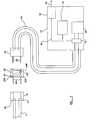
- Figure 2 is a diagrammatic illustration of a location device and anetwork appliance embodying the present invention.
- Referring now to Figure 1, a plan of a building or part of a building isgenerally shown at 10. The
building 10 is provided with a electrical mainspower system comprising a mainspower supply circuit 11 of conventional type which is provided with a plurality of mains poweroutlets comprising sockets 12 distributed throughout thebuilding 10 in conventional manner. A pluralityofnetwork appliances 13 are located within the building, in the presentexample purely by way of illustration comprisingpersonal computers 13a and13b,printers 14a and 14b, ascanner 15 and aserver 16. Thenetworkappliances 13 are interconnected by asuitable network 17. Each networkappliance is connected in conventional manner by apower cable 18 to amainssocket 12 of themain power circuit 11. - The
network 17 of Figure 1 is purely a diagrammatic illustration, andmay comprise an electrical connection such as Ethernet or FireWire, a radionetwork such as Bluetooth or 802.11 or any other appropriate network asdesired. Further, although Figure 1 shows a network located within a buildingor part of a building, it will be clear that the present invention may be used witha much more widely dispersed network or even with devices interconnected viathe internet. - Referring to Figure 2, a
socket 12 is shown in diagrammatic form with alive line 20 and aneutral line 21 connected to the mainspower supply circuit 11 in conventional manner. Thelocation device 19 comprises an appropriatenumber of pins, in this example two, to engage thesocket 12 to make anappropriate electrical connection. Thelocation device 19 similarly comprises alive line 23a and aneutral line 23b in conventional manner connected topins 22 to engage thesocket 12, and is provided with a suitable socket to receive apower connection comprising aplug 24 provided withpins 25 connected to apower line 18 for anetwork appliance 13. Thelocation device 19 provides athrough connection between thecorresponding pins network appliance 13 is able to draw power from the mains power supplycircuit via thesocket 12 in conventional manner. - The
location device 19 is provided with a location transmitter 26 and inthis example a filter 27. The location transmitter 26 comprises a memory 26ain which location information is held, and is operable to modulate the mainsalternating current such a way as to superimpose a location information signalencoding the location information on the alternating current. The filter 27 isarranged such that the location information signal superimposed on thealternating current is not transmitted into the mainspower supply circuit 11. - Provided in the
network appliance 13 is a power supply unit (PSU) 28 ofconventional type which is connected to theplug 24 andpins 25 to receivemains current via thepower cable 18 and transform or otherwise convert intothe mains current electrical power for supply to the components of thenetworkappliance 13. The modulation of the mains current by thelocation device 19 isof such a frequency and/or magnitude that the output of thePSU 28 is notaffected. In addition or alternatively, thePSU 28 may be provided with a filterto remove the modulation. - The
network appliance 13 in conventional manner has anetwork card 29to provide anetwork connection 30 and asuitable mother board 31, in thisexample interconnected by aconventional bus 32. Thenetwork appliance 13 isfurther provided with areader 33 which is able to detect the locationinformation signal superimposed on the mains alternating current by thelocation device 19. Thereader 33 then transmits the information via the bus, tothenetwork card 29 or themother board 31 or elsewhere as desired. - The invention thus provides a relatively inexpensive and simple methodof providing automatic location detection for a network appliance. A
locationdevice 19 is provided with location information and plugged into asocket 12.Alocation device 19 may of course be provided integrally with themainssocket 12 if desired. When anetwork appliance 13 is plugged into asocket 12comprising alocation device 19, the location device will transmit location information via thepower cord 18 on the mains alternating current where it isread by thereader 33 and made available to thenetwork appliance 13. Thelocation device 19 may, periodically transmit the location information, or maytransmit the location information in response to an enquiry from thenetworkappliance 13 transmitted by thereader 33, or may detect power being drawnfrom themains power circuit 11 by anetwork appliance 13, thus indicating thatanetwork appliance 13 has been plugged in and the power turned on andtransmit the location information in response. - The
network appliance 13 then makes the location information availableover thenetwork 17 toother network appliances 13. The location informationmay be encoded as desired. For example, the location information maycomprise a unique identification number associated with that location device.To provide a physical location, theserver 16 may have a table which gives aphysical location corresponding to the location information transmitted by eachlocation device so that theserver 16 acts as a name server maintaining themapping <socket location-signal, room-name> in a look up table.Alternatively, all of thenetwork appliances 13 may be provided with such alook up table. Further alternatively, the location information may actuallyencode details of the physical location stored in the store 26a, for example"room number 3, north west corner". The location information may be in anyformat and provided and accessed in any manner as desired. The locationinformation may be used for any application where physical locationinformation may be useful. - If the
network appliance 13 is subsequently moved to a different locationand is plugged into adifferent socket 12, it will then receive new locationinformation from thelocation device 19 connected with that socket, and will beable to make the new location information available over thenetwork 17. Thedevice's new physical location is thus made available automatically. - The location information signal may be superimposed on and read fromthe alternating mains current using any encoding and transmission protocol asdesired, for example the same technique as the X10 protocol or any othersuitably robust communication protocol and any appropriate electronicimplementation as necessary.
- It might be envisaged that the
network 17 comprises a power-linenetwork which uses the mainspower supply circuit 11 as a communicationsnetwork. In such circumstances the filter 27 may be omitted, or alternativelythe frequency at which the location information is transmitted by thelocationdevice 19 to thenetwork appliance 13 and the frequency at which thenetworkappliance 13 transmits the information over the power line network may bedifferent and the filter 27 may be selected to block the location informationsignal but not network transmissions to and from the mainpower supply circuit 11. - In the present specification "comprises" means "includes or consists ofand "comprising" means "including or consisting of'.
- The features disclosed in the foregoing description, or the followingclaims, or the accompanying drawings, expressed in their specific forms or interms of a means for performing the disclosed function, or a method or processfor attaining the disclosed result, as appropriate, may, separately, or in anycombination of such features, be utilised for realising the invention in diverseforms thereof.
Claims (12)
- A location device (19) connectable to a power outlet (12) of a mainspower system, the location device (19) being connectable to a powerconnection of a network appliance (13),characterised in that the location device (19) being operableto transmit location information to the network appliance (13) via said powerconnection.
- A location device (19) according to claim 1 wherein the locationinformation comprises an identification number corresponding to the locationdevice (19).
- A location device (19) according to claim 1 wherein the locationinformation encodes physical location information.
- A location device (19) according to any one of the preceding claimswherein the location information is transmitted periodically by the locationdevice (19) over the power connection.
- A location device according to any one of the preceding claims whereinthe location device (19) is operable to receive a location request from thenetwork appliance (13) and transmit location information in response to thelocation request.
- A location device (19) according to any one of the preceding claimsoperable to detect the power connection of a network appliance (13) andtransmit location information when a power connection is detected.
- A location device (19) according to any one of the preceding claimsfurther comprising a filter (27) whereby the location information is nottransmitted over the mains power system.
- A network appliance (13) comprising a power connection connectable toa mains power system,characterised in that the network appliance (13) further comprising a reader(33) operable to receive location information from a location device (19) viathe power connection.
- A network appliance (13) according to claim 8 comprising a networkconnection (30) whereby the network appliance (13) is operable to transmit thelocation information to another network appliance (13) via the networkconnection (30).
- A network comprising a server (16), a location device (19) according toany one of claims 1 to 7 and a network appliance (13) according to claim 8 orclaim 9 wherein the network appliance (13) is connected to the location device(19) and is operable to transmit the location information received from thelocation device (19) to the server (16) via the network connection (30).
- A network according to claim 10 wherein the server (16) compriseslocation device information whereby the server (16) can read the locationinformation received from the network appliance (13) and obtain acorresponding physical location for the network appliance (13).
- A network according to claim 11 wherein the location deviceinformation comprises a lookup table where the location information comprises an identification number and the lookup table comprises physical locationinformation corresponding to each identification number.
Priority Applications (3)
| Application Number | Priority Date | Filing Date | Title |
|---|---|---|---|
| DE60208325TDE60208325T2 (en) | 2002-01-21 | 2002-01-21 | Location device of a data network device |
| EP02354014AEP1330074B1 (en) | 2002-01-21 | 2002-01-21 | Location device of data network appliance |
| US10/349,504US6943683B2 (en) | 2002-01-21 | 2003-01-21 | Location device |
Applications Claiming Priority (1)
| Application Number | Priority Date | Filing Date | Title |
|---|---|---|---|
| EP02354014AEP1330074B1 (en) | 2002-01-21 | 2002-01-21 | Location device of data network appliance |
Publications (2)
| Publication Number | Publication Date |
|---|---|
| EP1330074A1 EP1330074A1 (en) | 2003-07-23 |
| EP1330074B1true EP1330074B1 (en) | 2005-12-28 |
Family
ID=8185726
Family Applications (1)
| Application Number | Title | Priority Date | Filing Date |
|---|---|---|---|
| EP02354014AExpired - LifetimeEP1330074B1 (en) | 2002-01-21 | 2002-01-21 | Location device of data network appliance |
Country Status (3)
| Country | Link |
|---|---|
| US (1) | US6943683B2 (en) |
| EP (1) | EP1330074B1 (en) |
| DE (1) | DE60208325T2 (en) |
Families Citing this family (52)
| Publication number | Priority date | Publication date | Assignee | Title |
|---|---|---|---|---|
| US6480510B1 (en) | 1998-07-28 | 2002-11-12 | Serconet Ltd. | Local area network of serial intelligent cells |
| US6956826B1 (en) | 1999-07-07 | 2005-10-18 | Serconet Ltd. | Local area network for distributing data communication, sensing and control signals |
| US6690677B1 (en) | 1999-07-20 | 2004-02-10 | Serconet Ltd. | Network for telephony and data communication |
| US6549616B1 (en) | 2000-03-20 | 2003-04-15 | Serconet Ltd. | Telephone outlet for implementing a local area network over telephone lines and a local area network using such outlets |
| IL135744A (en) | 2000-04-18 | 2008-08-07 | Mosaid Technologies Inc | Telephone communication system over a single telephone line |
| US6842459B1 (en) | 2000-04-19 | 2005-01-11 | Serconet Ltd. | Network combining wired and non-wired segments |
| IL144158A (en) | 2001-07-05 | 2011-06-30 | Mosaid Technologies Inc | Outlet for connecting an analog telephone set to a digital data network carrying voice signals in digital form |
| EP2234394A1 (en) | 2001-10-11 | 2010-09-29 | Mosaid Technologies Incorporated | Coupling device |
| IL152824A (en) | 2002-11-13 | 2012-05-31 | Mosaid Technologies Inc | Addressable outlet and a network using same |
| IL157787A (en) | 2003-09-07 | 2010-12-30 | Mosaid Technologies Inc | Modular outlet for data communications network |
| IL159838A0 (en) | 2004-01-13 | 2004-06-20 | Yehuda Binder | Information device |
| IL160417A (en) | 2004-02-16 | 2011-04-28 | Mosaid Technologies Inc | Outlet add-on module |
| KR100621104B1 (en)* | 2004-08-25 | 2006-09-19 | 삼성전자주식회사 | Electronics |
| US7382260B2 (en)* | 2004-09-01 | 2008-06-03 | Microsoft Corporation | Hot swap and plug-and-play for RFID devices |
| US8098158B2 (en)* | 2004-09-01 | 2012-01-17 | Microsoft Corporation | RFID server internals design |
| US7557707B2 (en)* | 2004-09-01 | 2009-07-07 | Microsoft Corporation | RFID enabled information systems utilizing a business application |
| US7204409B2 (en)* | 2004-09-01 | 2007-04-17 | Microsoft Corporation | Reader application markup language schema |
| US7701341B2 (en)* | 2004-09-01 | 2010-04-20 | Microsoft Corporation | Device service provider interface |
| US8217756B2 (en)* | 2004-09-01 | 2012-07-10 | Microsoft Corporation | Rule-based filtering and alerting |
| US7219834B2 (en)* | 2004-11-04 | 2007-05-22 | Footprint Systems Inc. | System and method for tracking installed equipment and deploying spare parts |
| US7873058B2 (en) | 2004-11-08 | 2011-01-18 | Mosaid Technologies Incorporated | Outlet with analog signal adapter, a method for use thereof and a network using said outlet |
| US20060123150A1 (en)* | 2004-11-24 | 2006-06-08 | Sharp Kabushiki Kaisha | Electronic apparatus and status information presenting apparatus |
| FI20050501L (en)* | 2005-05-11 | 2006-11-12 | Valtion Teknillinen | Remote sensor system and method and use of remote sensor |
| US7333002B2 (en)* | 2005-05-27 | 2008-02-19 | Ge Security, Inc. | Automatically tracking mobilized equipment and nurse call priority assignment system and method |
| US7378966B2 (en)* | 2006-01-04 | 2008-05-27 | Microsoft Corporation | RFID device groups |
| US7756747B2 (en)* | 2006-03-10 | 2010-07-13 | Microsoft Corporation | RFID business process-decoupling of design and deployment time activities |
| US20080010535A1 (en)* | 2006-06-09 | 2008-01-10 | Microsoft Corporation | Automated and configurable system for tests to be picked up and executed |
| US7868738B2 (en)* | 2006-06-15 | 2011-01-11 | Microsoft Corporation | Device simulator framework for an RFID infrastructure |
| US7956724B2 (en)* | 2006-06-15 | 2011-06-07 | Microsoft Corporation | Support for reliable end to end messaging of tags in an RFID infrastructure |
| US7675418B2 (en)* | 2006-06-15 | 2010-03-09 | Microsoft Corporation | Synchronous command model for RFID-enabling applications |
| US20080001711A1 (en)* | 2006-06-15 | 2008-01-03 | Microsoft Corporation | Reliability of execution for device provider implementations |
| US8207822B2 (en)* | 2006-06-15 | 2012-06-26 | Microsoft Corporation | Support for batching of events, and shredding of batched events in the RFID infrastructure platform |
| US7575160B2 (en)* | 2006-09-15 | 2009-08-18 | Ncr Corporation | Security validation of machine components |
| CN101601001B (en)* | 2006-12-08 | 2012-07-18 | 诺基亚公司 | Multiple connections to separate serial interfaces |
| JP5274769B2 (en)* | 2006-12-25 | 2013-08-28 | 株式会社東芝 | Equipment usage status management system |
| US20080160930A1 (en)* | 2007-01-03 | 2008-07-03 | Kimmo Kalliola | Positioning |
| US20100073234A1 (en)* | 2007-01-03 | 2010-03-25 | Nokia Corporation | Positioning |
| US20080174404A1 (en)* | 2007-01-23 | 2008-07-24 | Microsoft Corporation | Dynamic updates in rfid manager |
| US8245219B2 (en)* | 2007-01-25 | 2012-08-14 | Microsoft Corporation | Standardized mechanism for firmware upgrades of RFID devices |
| US20080303707A1 (en)* | 2007-06-07 | 2008-12-11 | Larsen Jan Pt | Wireless remote |
| DE102007032697A1 (en)* | 2007-07-13 | 2009-01-15 | Diehl Aerospace Gmbh | Method and device for determining the assignment of a device to one of several possible operating locations, in particular in the cabin of an aircraft |
| US8255090B2 (en)* | 2008-02-01 | 2012-08-28 | Energyhub | System and method for home energy monitor and control |
| US20090315715A1 (en)* | 2008-06-17 | 2009-12-24 | Larsen Jan Pt | Interactive desk unit |
| US20100091790A1 (en)* | 2008-10-15 | 2010-04-15 | Lockheed Martin Corporation | Patch identification beacon |
| US8760262B2 (en) | 2009-03-20 | 2014-06-24 | Lutron Electronics Co., Inc. | Method of automatically programming a load control device using a remote identification tag |
| US8683251B2 (en) | 2010-10-15 | 2014-03-25 | International Business Machines Corporation | Determining redundancy of power feeds connecting a server to a power supply |
| CN102323800A (en)* | 2011-05-31 | 2012-01-18 | 北京许继电气有限公司 | A smart home system based on the Internet of Things with panoramic electricity consumption information |
| RU2014131012A (en)* | 2011-12-27 | 2016-02-20 | Конинклейке Филипс Н.В. | ELECTRICAL CONNECTOR |
| SG11201502067XA (en) | 2012-10-02 | 2015-04-29 | Revport Group Fz Llc | Communicating digital display device |
| CN104769791B (en)* | 2012-11-09 | 2018-10-26 | 飞利浦灯具控股公司 | Electrical distribution rail system |
| US9647723B1 (en)* | 2015-10-22 | 2017-05-09 | Cisco Technology, Inc. | Data center management using device identification over power-line |
| CN109997367A (en)* | 2016-11-30 | 2019-07-09 | 松下知识产权经营株式会社 | Home appliance management system, plug, household appliance and controlling terminal |
Family Cites Families (5)
| Publication number | Priority date | Publication date | Assignee | Title |
|---|---|---|---|---|
| US5434775A (en)* | 1993-11-04 | 1995-07-18 | The General Hospital Corporation | Managing an inventory of devices |
| US5910776A (en)* | 1994-10-24 | 1999-06-08 | Id Technologies, Inc. | Method and apparatus for identifying locating or monitoring equipment or other objects |
| US6005476A (en)* | 1998-07-24 | 1999-12-21 | Valiulis; Carl | Electronic identification, control, and security system for consumer electronics and the like |
| AU6781500A (en)* | 1999-08-17 | 2001-03-13 | Microsoft Corporation | Device adapter for automation system |
| US6731201B1 (en)* | 2000-02-23 | 2004-05-04 | Robert Shaw Controls Company | Communications module and system |
- 2002
- 2002-01-21EPEP02354014Apatent/EP1330074B1/ennot_activeExpired - Lifetime
- 2002-01-21DEDE60208325Tpatent/DE60208325T2/ennot_activeExpired - Fee Related
- 2003
- 2003-01-21USUS10/349,504patent/US6943683B2/ennot_activeExpired - Lifetime
Also Published As
| Publication number | Publication date |
|---|---|
| US20030169156A1 (en) | 2003-09-11 |
| DE60208325T2 (en) | 2006-08-03 |
| US6943683B2 (en) | 2005-09-13 |
| EP1330074A1 (en) | 2003-07-23 |
| DE60208325D1 (en) | 2006-02-02 |
Similar Documents
| Publication | Publication Date | Title |
|---|---|---|
| EP1330074B1 (en) | Location device of data network appliance | |
| US7069345B2 (en) | Device identification and control in network environment | |
| CN101364911B (en) | Household appliance network system capable of realizing equipment recognition | |
| TW479195B (en) | A method and apparatus for an automatic multi-rate wireless/wired computer network | |
| CA1300713C (en) | Gateway for use in load control system | |
| US7142128B2 (en) | Portable information device, access device for portable information device, home network system, and home network access method | |
| Shahriyar et al. | Remote controlling of home appliances using mobile telephony | |
| CN101344985B (en) | Wireless remote control method | |
| US7853221B2 (en) | Network bridge device and methods for programming and using the same | |
| US9774668B2 (en) | Communication system for establishing P2P connections and the corresponding devices using the same | |
| CN103489304A (en) | Transfer equipment, transfer processing system and method | |
| US11606675B2 (en) | Methods and systems for wireless power source identification by generating one or more service set identifier (SSID) communication signals | |
| WO2015011465A1 (en) | A power socket terminal network, terminal and method | |
| US6771164B1 (en) | Automatic identification of local devices | |
| CN104378372B (en) | The method of electronic equipment and operation electronic equipment for communicating in a network | |
| US20170257225A1 (en) | Smart switch controlling system and method thereof | |
| US11476954B2 (en) | Methods and systems for wireless power source identification by generating one or more service set identifier (SSID) communication signals | |
| CN117254987A (en) | Communication method, communication device, and storage medium | |
| US20170126489A1 (en) | Auto-Commissioning of Lighting Resources | |
| KR20240123461A (en) | Method for communication of IoT devices and detection of security threats of IoT devices by IoT gateway | |
| JP4103499B2 (en) | Communication device | |
| EP4539607A1 (en) | Devices and methods for nfc-dali protocol conversion | |
| CN101218574A (en) | Legacy device bridge for residential or non-residential networks | |
| KR102675964B1 (en) | Method of communication between IoT gateway and IoT devices with various protocols | |
| KR20020047626A (en) | Apparatus of remote controlling for household appliances |
Legal Events
| Date | Code | Title | Description |
|---|---|---|---|
| PUAI | Public reference made under article 153(3) epc to a published international application that has entered the european phase | Free format text:ORIGINAL CODE: 0009012 | |
| AK | Designated contracting states | Designated state(s):AT BE CH CY DE DK ES FI FR GB GR IE IT LI LU MC NL PT SE TR | |
| AX | Request for extension of the european patent | Extension state:AL LT LV MK RO SI | |
| 17P | Request for examination filed | Effective date:20040109 | |
| AKX | Designation fees paid | Designated state(s):DE FR GB | |
| GRAP | Despatch of communication of intention to grant a patent | Free format text:ORIGINAL CODE: EPIDOSNIGR1 | |
| GRAS | Grant fee paid | Free format text:ORIGINAL CODE: EPIDOSNIGR3 | |
| GRAA | (expected) grant | Free format text:ORIGINAL CODE: 0009210 | |
| AK | Designated contracting states | Kind code of ref document:B1 Designated state(s):DE FR GB | |
| REG | Reference to a national code | Ref country code:GB Ref legal event code:FG4D | |
| REF | Corresponds to: | Ref document number:60208325 Country of ref document:DE Date of ref document:20060202 Kind code of ref document:P | |
| ET | Fr: translation filed | ||
| PLBE | No opposition filed within time limit | Free format text:ORIGINAL CODE: 0009261 | |
| STAA | Information on the status of an ep patent application or granted ep patent | Free format text:STATUS: NO OPPOSITION FILED WITHIN TIME LIMIT | |
| 26N | No opposition filed | Effective date:20060929 | |
| PGFP | Annual fee paid to national office [announced via postgrant information from national office to epo] | Ref country code:GB Payment date:20080129 Year of fee payment:7 | |
| PGFP | Annual fee paid to national office [announced via postgrant information from national office to epo] | Ref country code:DE Payment date:20080229 Year of fee payment:7 Ref country code:FR Payment date:20080117 Year of fee payment:7 | |
| GBPC | Gb: european patent ceased through non-payment of renewal fee | Effective date:20090121 | |
| PG25 | Lapsed in a contracting state [announced via postgrant information from national office to epo] | Ref country code:DE Free format text:LAPSE BECAUSE OF NON-PAYMENT OF DUE FEES Effective date:20090801 | |
| REG | Reference to a national code | Ref country code:FR Ref legal event code:ST Effective date:20091030 | |
| PG25 | Lapsed in a contracting state [announced via postgrant information from national office to epo] | Ref country code:GB Free format text:LAPSE BECAUSE OF NON-PAYMENT OF DUE FEES Effective date:20090121 | |
| PG25 | Lapsed in a contracting state [announced via postgrant information from national office to epo] | Ref country code:FR Free format text:LAPSE BECAUSE OF NON-PAYMENT OF DUE FEES Effective date:20090202 |