EP1328192B1 - Integrated sample testing meter - Google Patents
Integrated sample testing meterDownload PDFInfo
- Publication number
- EP1328192B1 EP1328192B1EP02713061AEP02713061AEP1328192B1EP 1328192 B1EP1328192 B1EP 1328192B1EP 02713061 AEP02713061 AEP 02713061AEP 02713061 AEP02713061 AEP 02713061AEP 1328192 B1EP1328192 B1EP 1328192B1
- Authority
- EP
- European Patent Office
- Prior art keywords
- meter
- lancet
- sample
- strip
- cartridge
- Prior art date
- Legal status (The legal status is an assumption and is not a legal conclusion. Google has not performed a legal analysis and makes no representation as to the accuracy of the status listed.)
- Expired - Lifetime
Links
- 238000012360testing methodMethods0.000titleclaimsabstractdescription250
- 239000012530fluidSubstances0.000claimsdescription17
- 239000000463materialSubstances0.000claimsdescription14
- 230000033001locomotionEffects0.000claimsdescription11
- 239000008280bloodSubstances0.000abstractdescription88
- 210000004369bloodAnatomy0.000abstractdescription88
- 238000012546transferMethods0.000abstractdescription13
- 238000000840electrochemical analysisMethods0.000abstractdescription6
- 238000005375photometryMethods0.000abstractdescription3
- WQZGKKKJIJFFOK-GASJEMHNSA-NGlucoseNatural productsOC[C@H]1OC(O)[C@H](O)[C@@H](O)[C@@H]1OWQZGKKKJIJFFOK-GASJEMHNSA-N0.000description35
- 239000008103glucoseSubstances0.000description35
- 238000004458analytical methodMethods0.000description27
- 230000007246mechanismEffects0.000description18
- 238000005070samplingMethods0.000description18
- 230000002500effect on skinEffects0.000description13
- 210000001519tissueAnatomy0.000description13
- 238000012544monitoring processMethods0.000description12
- 238000005259measurementMethods0.000description10
- 238000013461designMethods0.000description9
- 238000000034methodMethods0.000description7
- 239000012491analyteSubstances0.000description6
- 230000004438eyesightEffects0.000description6
- 206010012601diabetes mellitusDiseases0.000description5
- 230000000694effectsEffects0.000description5
- 210000003722extracellular fluidAnatomy0.000description5
- 210000001124body fluidAnatomy0.000description4
- 230000008859changeEffects0.000description4
- 230000000994depressogenic effectEffects0.000description4
- 210000000245forearmAnatomy0.000description4
- 230000006870functionEffects0.000description4
- 229920003023plasticPolymers0.000description4
- 238000003825pressingMethods0.000description4
- 230000008569processEffects0.000description4
- 230000004913activationEffects0.000description3
- 230000008901benefitEffects0.000description3
- 230000006835compressionEffects0.000description3
- 238000007906compressionMethods0.000description3
- 230000007423decreaseEffects0.000description3
- 230000006872improvementEffects0.000description3
- 239000004033plasticSubstances0.000description3
- 206010052428WoundDiseases0.000description2
- 230000017531blood circulationEffects0.000description2
- 238000010276constructionMethods0.000description2
- 238000007405data analysisMethods0.000description2
- 239000002274desiccantSubstances0.000description2
- 229920001971elastomerPolymers0.000description2
- 238000005516engineering processMethods0.000description2
- 239000004816latexSubstances0.000description2
- 229920000126latexPolymers0.000description2
- 230000007935neutral effectEffects0.000description2
- 239000004814polyurethaneSubstances0.000description2
- 229920002635polyurethanePolymers0.000description2
- 238000012545processingMethods0.000description2
- 238000007789sealingMethods0.000description2
- 230000007704transitionEffects0.000description2
- 230000000007visual effectEffects0.000description2
- 201000004569BlindnessDiseases0.000description1
- 208000024172Cardiovascular diseaseDiseases0.000description1
- 208000002249Diabetes ComplicationsDiseases0.000description1
- 208000028389Nerve injuryDiseases0.000description1
- 208000003251PruritusDiseases0.000description1
- 229920000122acrylonitrile butadiene styrenePolymers0.000description1
- 230000009471actionEffects0.000description1
- 238000013019agitationMethods0.000description1
- 230000000712assemblyEffects0.000description1
- 238000000429assemblyMethods0.000description1
- 230000004888barrier functionEffects0.000description1
- 238000010241blood samplingMethods0.000description1
- 210000000746body regionAnatomy0.000description1
- 210000004027cellAnatomy0.000description1
- 230000001010compromised effectEffects0.000description1
- 238000011109contaminationMethods0.000description1
- 239000013256coordination polymerSubstances0.000description1
- 230000003247decreasing effectEffects0.000description1
- 230000000881depressing effectEffects0.000description1
- 238000001514detection methodMethods0.000description1
- 238000002848electrochemical methodMethods0.000description1
- 230000003203everyday effectEffects0.000description1
- 229920002457flexible plasticPolymers0.000description1
- 230000036541healthEffects0.000description1
- 230000010354integrationEffects0.000description1
- 230000007803itchingEffects0.000description1
- 208000017169kidney diseaseDiseases0.000description1
- 235000021190leftoversNutrition0.000description1
- 238000004519manufacturing processMethods0.000description1
- 239000012528membraneSubstances0.000description1
- 230000008764nerve damageEffects0.000description1
- 210000001640nerve endingAnatomy0.000description1
- 210000000929nociceptorAnatomy0.000description1
- 230000035515penetrationEffects0.000description1
- 230000009467reductionEffects0.000description1
- 239000012858resilient materialSubstances0.000description1
- 238000010561standard procedureMethods0.000description1
- 239000000126substanceSubstances0.000description1
- 239000012780transparent materialSubstances0.000description1
- 239000002699waste materialSubstances0.000description1
- 230000003245working effectEffects0.000description1
Images


Classifications
- A—HUMAN NECESSITIES
- A61—MEDICAL OR VETERINARY SCIENCE; HYGIENE
- A61B—DIAGNOSIS; SURGERY; IDENTIFICATION
- A61B5/00—Measuring for diagnostic purposes; Identification of persons
- A61B5/14—Devices for taking samples of blood ; Measuring characteristics of blood in vivo, e.g. gas concentration within the blood, pH-value of blood
- G—PHYSICS
- G01—MEASURING; TESTING
- G01N—INVESTIGATING OR ANALYSING MATERIALS BY DETERMINING THEIR CHEMICAL OR PHYSICAL PROPERTIES
- G01N33/00—Investigating or analysing materials by specific methods not covered by groups G01N1/00 - G01N31/00
- G01N33/48—Biological material, e.g. blood, urine; Haemocytometers
- G01N33/483—Physical analysis of biological material
- G01N33/487—Physical analysis of biological material of liquid biological material
- G01N33/4875—Details of handling test elements, e.g. dispensing or storage, not specific to a particular test method
- G01N33/48757—Test elements dispensed from a stack
- A—HUMAN NECESSITIES
- A61—MEDICAL OR VETERINARY SCIENCE; HYGIENE
- A61B—DIAGNOSIS; SURGERY; IDENTIFICATION
- A61B5/00—Measuring for diagnostic purposes; Identification of persons
- A61B5/15—Devices for taking samples of blood
- A61B5/150007—Details
- A61B5/150015—Source of blood
- A61B5/150022—Source of blood for capillary blood or interstitial fluid
- A—HUMAN NECESSITIES
- A61—MEDICAL OR VETERINARY SCIENCE; HYGIENE
- A61B—DIAGNOSIS; SURGERY; IDENTIFICATION
- A61B5/00—Measuring for diagnostic purposes; Identification of persons
- A61B5/15—Devices for taking samples of blood
- A61B5/150007—Details
- A61B5/150053—Details for enhanced collection of blood or interstitial fluid at the sample site, e.g. by applying compression, heat, vibration, ultrasound, suction or vacuum to tissue; for reduction of pain or discomfort; Skin piercing elements, e.g. blades, needles, lancets or canulas, with adjustable piercing speed
- A61B5/150061—Means for enhancing collection
- A61B5/150068—Means for enhancing collection by tissue compression, e.g. with specially designed surface of device contacting the skin area to be pierced
- A—HUMAN NECESSITIES
- A61—MEDICAL OR VETERINARY SCIENCE; HYGIENE
- A61B—DIAGNOSIS; SURGERY; IDENTIFICATION
- A61B5/00—Measuring for diagnostic purposes; Identification of persons
- A61B5/15—Devices for taking samples of blood
- A61B5/150007—Details
- A61B5/150175—Adjustment of penetration depth
- A61B5/150198—Depth adjustment mechanism at the proximal end of the carrier of the piercing element
- A—HUMAN NECESSITIES
- A61—MEDICAL OR VETERINARY SCIENCE; HYGIENE
- A61B—DIAGNOSIS; SURGERY; IDENTIFICATION
- A61B5/00—Measuring for diagnostic purposes; Identification of persons
- A61B5/15—Devices for taking samples of blood
- A61B5/150007—Details
- A61B5/150358—Strips for collecting blood, e.g. absorbent
- A—HUMAN NECESSITIES
- A61—MEDICAL OR VETERINARY SCIENCE; HYGIENE
- A61B—DIAGNOSIS; SURGERY; IDENTIFICATION
- A61B5/00—Measuring for diagnostic purposes; Identification of persons
- A61B5/15—Devices for taking samples of blood
- A61B5/150007—Details
- A61B5/150374—Details of piercing elements or protective means for preventing accidental injuries by such piercing elements
- A61B5/150381—Design of piercing elements
- A61B5/150412—Pointed piercing elements, e.g. needles, lancets for piercing the skin
- A—HUMAN NECESSITIES
- A61—MEDICAL OR VETERINARY SCIENCE; HYGIENE
- A61B—DIAGNOSIS; SURGERY; IDENTIFICATION
- A61B5/00—Measuring for diagnostic purposes; Identification of persons
- A61B5/15—Devices for taking samples of blood
- A61B5/150007—Details
- A61B5/150374—Details of piercing elements or protective means for preventing accidental injuries by such piercing elements
- A61B5/150381—Design of piercing elements
- A61B5/150503—Single-ended needles
- A—HUMAN NECESSITIES
- A61—MEDICAL OR VETERINARY SCIENCE; HYGIENE
- A61B—DIAGNOSIS; SURGERY; IDENTIFICATION
- A61B5/00—Measuring for diagnostic purposes; Identification of persons
- A61B5/15—Devices for taking samples of blood
- A61B5/150007—Details
- A61B5/150748—Having means for aiding positioning of the piercing device at a location where the body is to be pierced
- A—HUMAN NECESSITIES
- A61—MEDICAL OR VETERINARY SCIENCE; HYGIENE
- A61B—DIAGNOSIS; SURGERY; IDENTIFICATION
- A61B5/00—Measuring for diagnostic purposes; Identification of persons
- A61B5/15—Devices for taking samples of blood
- A61B5/151—Devices specially adapted for taking samples of capillary blood, e.g. by lancets, needles or blades
- A61B5/15101—Details
- A61B5/15103—Piercing procedure
- A61B5/15107—Piercing being assisted by a triggering mechanism
- A61B5/15113—Manually triggered, i.e. the triggering requires a deliberate action by the user such as pressing a drive button
- A—HUMAN NECESSITIES
- A61—MEDICAL OR VETERINARY SCIENCE; HYGIENE
- A61B—DIAGNOSIS; SURGERY; IDENTIFICATION
- A61B5/00—Measuring for diagnostic purposes; Identification of persons
- A61B5/15—Devices for taking samples of blood
- A61B5/151—Devices specially adapted for taking samples of capillary blood, e.g. by lancets, needles or blades
- A61B5/15101—Details
- A61B5/15115—Driving means for propelling the piercing element to pierce the skin, e.g. comprising mechanisms based on shape memory alloys, magnetism, solenoids, piezoelectric effect, biased elements, resilient elements, vacuum or compressed fluids
- A61B5/15117—Driving means for propelling the piercing element to pierce the skin, e.g. comprising mechanisms based on shape memory alloys, magnetism, solenoids, piezoelectric effect, biased elements, resilient elements, vacuum or compressed fluids comprising biased elements, resilient elements or a spring, e.g. a helical spring, leaf spring, or elastic strap
- A—HUMAN NECESSITIES
- A61—MEDICAL OR VETERINARY SCIENCE; HYGIENE
- A61B—DIAGNOSIS; SURGERY; IDENTIFICATION
- A61B5/00—Measuring for diagnostic purposes; Identification of persons
- A61B5/15—Devices for taking samples of blood
- A61B5/151—Devices specially adapted for taking samples of capillary blood, e.g. by lancets, needles or blades
- A61B5/15186—Devices loaded with a single lancet, i.e. a single lancet with or without a casing is loaded into a reusable drive device and then discarded after use; drive devices reloadable for multiple use
- A61B5/15188—Constructional features of reusable driving devices
- A61B5/1519—Constructional features of reusable driving devices comprising driving means, e.g. a spring, for propelling the piercing unit
- A—HUMAN NECESSITIES
- A61—MEDICAL OR VETERINARY SCIENCE; HYGIENE
- A61B—DIAGNOSIS; SURGERY; IDENTIFICATION
- A61B5/00—Measuring for diagnostic purposes; Identification of persons
- A61B5/15—Devices for taking samples of blood
- A61B5/151—Devices specially adapted for taking samples of capillary blood, e.g. by lancets, needles or blades
- A61B5/15186—Devices loaded with a single lancet, i.e. a single lancet with or without a casing is loaded into a reusable drive device and then discarded after use; drive devices reloadable for multiple use
- A61B5/15188—Constructional features of reusable driving devices
- A61B5/15192—Constructional features of reusable driving devices comprising driving means, e.g. a spring, for retracting the lancet unit into the driving device housing
- A61B5/15194—Constructional features of reusable driving devices comprising driving means, e.g. a spring, for retracting the lancet unit into the driving device housing fully automatically retracted, i.e. the retraction does not require a deliberate action by the user, e.g. by terminating the contact with the patient's skin
- A—HUMAN NECESSITIES
- A61—MEDICAL OR VETERINARY SCIENCE; HYGIENE
- A61B—DIAGNOSIS; SURGERY; IDENTIFICATION
- A61B5/00—Measuring for diagnostic purposes; Identification of persons
- A61B5/15—Devices for taking samples of blood
- A61B5/157—Devices characterised by integrated means for measuring characteristics of blood
Definitions
- the present inventionrelates to an integrated sample testing meter for use in sampling and analyzing analytes, particularly glucose, in fluids such as blood or interstitial fluid.
- Glucose monitoringis a fact of everyday life for diabetic individuals. The accuracy of such monitoring can literally mean the difference between life and death. Generally, a diabetic patient measures blood glucose levels several times a day to monitor and control blood sugar levels. Failure to test blood glucose levels accurately and on a regular basis can result in serious diabetes-related complications, including cardiovascular disease, kidney disease, nerve damage and blindness. A number of glucose meters are currently available which permit an individual to test the glucose level in a small sample of blood.
- the fingertipWhile the fingertip is generally used for sampling blood, due to the rich capillary bed of the skin of the fingertip, the fingertip is also particularly sensitive to pain, due to a rich supply of pain receptors in the finger tip as well.
- a punctureis too deep, too close to a recent puncture or not deep enough and requires an additional puncture, the pain increases significantly. Pain may also be increased if the lancet penetrates slowly or is withdrawn slowly.
- the usermay be forced to make a larger puncture than is necessary to form a sufficient amount of blood, due to losses during the transfer between the puncture site and the test strip.
- the process of measuring blood glucose levelsrequires several steps and several different accessories, including a lancing device, a lancet, a supply of test strips and a glucose meter.
- Each accessoryhas a different function.
- the usermust have a flat surface available to unpack and lay down the accessories within easy reach. This, by itself, poses a challenge for those who need to take measurements while participating in outdoor activities. Flat surfaces are often not available and this can discourage a person from taking a measurement. This can be disadvantageous because blood glucose levels may change significantly during an outdoor activity.
- the usercharges the lancing device with a fresh lancet; opens a vial of strips; removes a strip; inserts the strip into the meter; re-closes the vial; checks for the correct calibration code on the meter; picks up the lancing device; lances the skin of the finger or other body part; lays down the lancing device; squeezes or massages the finger to yield an adequate blood sample; transfers the sample to the test strip for analysis; waits for the meter to analyze the sample; removes the strip from the test meter; discards the strip; and finally re-packs all of the accessories.
- the standard procedure for taking a glucose measurementrequires the use of multiple, separate components and the execution of a number of steps requiring manual user intervention.
- test stripsare quite small and the sample-recciving area is therefore even smaller. This transfer step is a difficult task for many users.
- test stripsrequiring ever smaller amounts of sample. (This allows the use of smaller punctures and therefore less painful lancing.)
- the use of smaller samplesincreases the difficulty in transferring the sample to the sample-receiving area on the test strip. This is especially difficult for users with poor eyesight, a common complication for diabetics.
- DE 19819401discloses a testing meter with cartridge and automatic mechanism to bring the strip in the measuring position.
- the present inventionprovides an integrated sample-testing meter comprising a single modular housing as defined in appended claim 1. Further preferred features of the invention are defined in subclaims 2-10.
- the meter of the present inventionpreferably includes electrical or electronic circuitry for controlling its operation.
- Such circuitrymay be hard-wired or may comprise a microcomputer or similar device.
- Such circuitrywill in particular include all the components of the sensor and will be arranged to carry out the analysis of the sample.
- the circuitryalso includes a visual display unit from which the user can read out the results of any particular test.
- the displaymay also be adapted to provide a display of the data, as explained in more detail below.
- the circuitryincludes means, such as a touch sensitive display, a microphone and voice activated software or control buttons, for entering data into the meter.
- meanssuch as a touch sensitive display, a microphone and voice activated software or control buttons, for entering data into the meter.
- the meteris arranged such that, in use, when strip is in the sample-receiving position, its sample receiving area is spaced from the puncture site by a distance of from about 0.4 mm to about 1.3 mm and preferably by a distance of about 0.7 mm to about 0.9 mm.
- the pressure devicemay comprise a pump adapted to apply a negative pressure to a volume in the meter having an aperture for location on the skin of the user.
- the pressure devicecomprises a pressure ring arranged to be located, in use, on the user's skin and to apply pressure at the edges of the ring to increase the amount of fluid available at the centre of the ring.
- the pressure ringmay be shaped to conform to the shape of the area of the skin to which it is to be applied. For instance, if the meter is intended for use on the forearm, the pressure ring will be generally planar. However, if the meter is intended for use on a finger, the pressure ring will be curved.
- the pressure ringhas a multi-contoured surface to increase the pressure gradient from the outside to the inside of the ring.
- the pressure ringis part of a lancet cap which covers the lancet in its retracted position.
- the lancet capincludes a means, such as a side wall, which co-operates with the lancet drive train to ensure that the lancet travels along approximately the same path on each activation of the drive train.
- the lancet capmay be an integral part of the housing. Preferably, however, the lancet cap is detachably mounted on the housing. This may be achieved by use of screwthread or bayonet type fixings or by use .of a snap fit connection.
- the metercan include at least two interchangeable lancet caps, for instance a lancet cap for forearm use and a lancet cap for finger use.
- the lancetmay be any of the types of lancet at present in use in the art.
- the term "lancet"includes finger-sticking devices of the type known in the art.
- the lancetis removably attached to the lancet drive train so that the lancet can be disposed of after one or several uses.
- the lancet drive trainis spring driven.
- the lancet drive trainis driven electromagnetically.
- the drive trainis arranged such that, on actuation, the lancet moves to the extended position and is retracted.
- the lancet drive trainincludes an adjustment screw which allows the user to set the extended position of the lancet. This enables the user to calibrate the operation of the meter such that his or her skin is punctured sufficiently to allow a large enough drop of fluid to form without causing too much pain.
- the operation of the adjustment screwis arranged such that the distance of travel of the lancet remains constant, however much the extended position of the lancet is changed. This ensures that the amount of pain experienced by the user does not increase disproportionately to the depth of puncture.
- the lancet capprovides a means for guiding the lancet drive train so that the lancet punctures ' the skin at approximately the same place on each actuation of the drive train.
- the lancet drive trainis arranged such that the end of the lancet, in its extended position, extends to approximately the plane formed by the pressure ring or aperture in the housing which, in use, is placed on the user's skin.
- the test strip cartridgecomprises a cartridge housing defining a cavity configured to receive a stack of test strips, a partially detachable cartridge cap and a means for moving the stack of test strips towards the cartridge cap.
- the cartridgeincludes a seal for sealing the cartridge cap to the cartridge housing when the cartridge cap is fully engaged with the cartridge housing.
- the sealmay be on the cartridge cap or on the cartridge housing.
- the cartridgemay be manufactured from a material having dessicant properties, or a dessicant may be contained within the cartridge.
- the cartridge capIn use, upon activation of the meter, the cartridge cap is partially detached from the cartridge housing to allow the first test strip in the stack to be moved by the test strip dispensing system to the sample-receiving position. Once the measurement has been taken, the cartridge cap is preferably manually replaced on the cartridge housing to close the cartridge and seal its contents from atmospheric effects.
- the cartridgehas on it data relating to the calibration code for the strips in the cartridge.
- the datamay be present as visually readable indicia.
- the metermust include means, as mentioned above, to allow the user to enter the calibration code into the meter.
- the data on the cartridgeare present in machine-readable format, for instance as a bar code or a resistance bridge circuit or stored in an electronic memory module.
- the meterwill include a bar code reader.
- Thismay be a scanning reader or a stationary reader.
- a scanning readerwill be more complicated but can be used when the cartridge is fitted in the meter.
- a stationary readeris less complicated but can only be used as the cartridge is inserted into or taken out of the meter.
- thismay comprise a read-only memory (ROM), or a rewritable memory, such as an EEPROM.
- ROMread-only memory
- EEPROMEEPROM
- the dataalso include a unique number identifying the specific cartridge, the number of strips originally present in the cartridge, the expiry date for the cartridge, different calibration factors for different sources of fluid (neonatal, arterial or venous blood, for instance) and any other relevant information such as control solution range information, preferably in machine-readable format, to assist in operation of the meter.
- the metermay be arranged to write back into the memory module information such as the number of strips used, the date the cartridge was first used, the length of time the cartridge has remained open and the date, time and result of each test that was carried out with a strip from the cartridge.
- the test strip dispensing systemincludes a slider adapted to engage with only one of the test strips in the cartridge and move it to the sample-receiving position.
- the meterincludes a feeding channel which receives the strip from the cartridge and guides it to the sample-receiving position.
- the feeding channelincludes a step arranged such, when the strip has been moved past the step, the strip drops, or is forced, into the step, thereby preventing the strip from moving back towards the cartridge.
- the stripis forced into the step by springs located on the meter.
- the springsare also electrically conductive and are arranged to make electrical contact with electrodes or a conductive bar on the strip (see below).
- the feeding channelis arranged such that the major plane of the strip, when in the sample-receiving position, is at an angle of from about 30° to about 60°, preferably about 45°, to the direction of movement of the lancet towards its extended position.
- the meterincludes an ejection means for ejecting a used test strip from the mete once a test has been completed.
- the ejection meansis operated as the cartridge cap is closed.
- the meterincludes a deviator which prevents the test strip dispensing system moving a further test strip into the sample-receiving position while a first test strip is still in position.
- a deviatorwhich prevents the test strip dispensing system moving a further test strip into the sample-receiving position while a first test strip is still in position.
- the deviatoroperates in conjunction with the cartridge cap. While the cartridge cap is partially detached from the cartridge housing, the deviator blocks the normal path for the test strip dispensing system, such as the slider, and causes it to enter the cartridge cap.
- the meterincludes a means for verifying that a strip is in the sample-receiving position.
- Thismay comprise a reflectance meter.
- test stripsare more or less reflective than the surfaces of the feeding channel. Therefore, a change in reflectance will indicate that a test strip is in position.
- the verifying meanscomprises an electrical system.
- each stripmay have on it a conductive bar arranged to short out two electrodes on the meter. This arrangement is useful for strips arranged to carry out photometric measurements.
- the verifying meansmay include electrical contacts on the meter which contact the electrodes on the strip.
- the electrical contacts on the meterare spring loaded and are positioned to force the strip into the step in the feeding channel.
- the verifying meansis also used to activate fully the circuitry in the meter.
- the metermay normally be in a low power mode, where the only active circuitry is that used to control the verifying means. Once the verifying means has indicated that a strip is present, the meter can then automatically switch to high power mode where all its relevant circuits are functioning.
- the verifying meansis also arranged to start a timer in the circuitry of the meter.
- the timeris stopped by the ejection of a used strip from the meter, preferably by closure of the cartridge cap.
- the circuitryis arranged to sum the total time that the cartridge has been open and to produce a warning signal, such as an audible tone or a visible signal, if the total exceeds a pre-set maximum.
- the circuitry in the meteralso counts the number of strips dispensed from each cartridge.
- the circuitryis designed to provide a warning signal, such as an audible tone or a visible signal, when the number of strips remaining the cartridge is low.
- the cartridgepreferably includes a rewritable memory module and the circuitry in the meter is arranged to write back to the cartridge memory module useful information, such as the number of strips remaining in the cartridge and the length of time the cartridge has been open to the atmosphere.
- useful informationsuch as the number of strips remaining in the cartridge and the length of time the cartridge has been open to the atmosphere.
- the rewriting functionis particularly useful where a user is likely to be away from his normal environment for a length of time which would require the use of more strips than are present in a cartridge. In such cases, a user is likely to remove the old cartridge and insert a new, full cartridge. Once the new cartridge has been used up, the user may insert the old cartridge, even if it is out of date. As long as the meter can read the data on the old cartridge, it will be able to decide whether use of the old cartridge should be allowed.
- a rewritable memory moduleenables other possible uses. For instance, data on time and date of use and result of measurement may be written into the cartridge's memory module. The used cartridge could then be returned to the user's health care provider who could then study: the data to determine whether the user is complying with his treatment and monitoring regime. Alternatively, the used cartridges could be returned to the manufacturer to enable a general study of use to be carried out.
- the meteris activated manually by use of a single movement, for instance of a multi-functional handle assembly carried by the housing.
- the handle assemblymay include a lever pivoted to the housing.
- the actuation of the handle assemblycocks the lancet drive train and moves a single test strip into the sample-receiving position.
- the movement of the handle assemblymay also activate all the meter's circuitry.
- the lancet drive trainmay be fired either by further movement of the lever or, preferably, by actuation of a trigger.
- the use of the integrated sample testing meter of the present inventioncan be very simple. If desired, the user can replace an existing lancet with a new one. The meter can then be cocked by use of the handle assembly. This also moves a strip into the sample-receiving position. Movement of the lever or receipt of a strip in the sample receiving position also activates all the meter's circuitry. Then, the user only has to place the appropriate part of the meter, such as an aperture or the lancet cap, on his skin and activate the trigger.
- the metercan be cocked, positioned and fired again, if necessary a number of times, without the need to insert a new strip.
- the presence of the pressure deviceensures that, once a reasonable puncture is made, sufficient fluid will accumulate around the puncture so that it will contact the sample-receiving area of the strip and a sample will be taken onto or into the strip.
- the use of the meter of the present inventionavoids most of the steps presently required and in particular avoids those steps where manual dexterity and good eyesight are advantageous.
- the meteris adapted to produce and analyze a sample of blood or interstitial fluid, in particular to analyze a blood sample for glucose levels.
- Strips adapted to carry out such measurementsare well known in the art. These may be electrochemical or photometric strips.
- the stripsare adapted to carry out electrochemical analyses and the circuitry in the meter is arranged to contact the electrodes in such strips.
- the present inventionprovides an integrated blood glucose testing meter.
- the integrated meter of this aspect of the present inventionallows for a simple, one-step glucose monitoring process, and significantly reduces the obstacles involved in frequent glucose monitoring.
- the integrated meterprovides for the automated and precise dispensing and positioning of a test strip in repeatable close proximity to a lancet puncture site, automated transfer of a blood sample to the test strip and automated analysis of the blood sample after the test strip collects the sample from the puncture site.
- a disposable test strip cartridgeadapted to be loaded into the meter of the present invention.
- the cartridgeincludes a cartridge housing defining a cavity configured to receive a stack of test strips, a partially detachable cartridge cap and a stack of test strips disposed in the cavity.
- the present inventionprovides a multi-function handle assembly for the meter of the present invention.
- the handle assemblycomprises a lever.
- the leverWhen a user depresses the handle assembly, the lever simultaneously cocks a lancing device and dispenses one test strip from the test strip cartridge into the sample-receiving position.
- the test stripis precisely positioned at a predetermined distance from the lancet.
- the present inventionprovides a strip dispensing system for forwarding test strips from a test strip cartridge to the sample-receiving position in the meter of the present invention on a one-by-one basis.
- the strip dispensing systemincludes a slider for pushing a test strip from the cartridge to a feeding channel and a deviator for preventing a plurality of test strips from being positioned in the feeding channel at one time. The deviator diverts the slider inside the test cartridge cap when a test strip is positioned in the feeding channel.
- the present inventionmakes possible an integrated method of sampling and testing a blood glucose level or other analyte in a bodily fluid.
- Such an integrated methodmay comprise loading a test strip cartridge into an integrated testing meter, depressing a handle assembly on the testing meter to cock a lancing device and push a test strip into a sample-receiving position, pressing the integrated testing meter on the skin of a user and pressing a trigger of the testing meter to drive a lancet into the skin in order to form a drop of blood or other fluid on the skin surface.
- the test stripabsorbs a required amount of blood or other fluid for an automated analysis of the sample by the integrated testing meter.
- the present inventionprovides an integrated meter for sampling and analyzing a sample of bodily fluid, such as blood, including a disposable test strip cartridge having a stack of test strips disposed therein.
- the present inventionfacilitates the monitoring of, for instance; blood glucose levels by integrating into a single meter the steps involved in sampling and analyzing blood into a simple process employing a single meter.
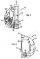
- FIGs 1 and 2illustrate an integrated blood glucose sampling and testing meter 10 according to an illustrative embodiment of the present invention.
- This meteris designed to carry out electrochemical analysis of a blood sample. However, if desired, the same mechanical parts could be used in connection with photometric analyses.
- the sampling and testing metercomprises a modular housing 11 (shown in Figure 2 ) encompassing an integrated system for expressing and subsequently analyzing a sample.
- the meter 10includes a lancet assembly for puncturing the skin of a user to express a drop of blood on the surface of the skin.
- the lancet assemblyincludes a lancet 13 and a lancet drive train 14 for driving the lancet into and out of the skin. When cocked, a triggering button 15 actuates the drive train.
- a lancet cap 16is removably attached to the housing 11 at the proximal end of the device 10 and includes an aperture to allow passage of the lancet 13 through the cap 16 and into the skin of the user.
- the cap 16can have a multi-contoured surface in order to promote, enhance or facilitate the expression of blood by pressing the device onto the skin.
- the lancet assemblyfurther includes a depth adjustment knob 17 situated at the distal end of the drive train opposite the lancet. Rotation of the depth adjustment knob decreases or increases the puncture depth of the lancet. The depth adjustment knob regulates or adjusts the puncture depth in accordance with known techniques.
- a test strip cartridge 18is loaded into the meter 10 and includes a stacked supply of test strips disposed within a cavity or hollow interior of the cartridge housing.
- the test strip cartridgeis adapted to dispense individual test strips to a feeding channel 19.
- the outlet of the feeding channelleads into the interior of the lancing cap 16, in precise and close proximity to the aperture through which the lancet 13 passes when puncturing the skin.
- the test stripis located in close proximity to the puncture wound to ensure that blood contacts the strip.
- the precise positioning of the test strip adjacent the lancetensures that only small volumes of blood are required, as the strip is able to touch and automatically wick up even a small drop of blood.
- the housingincludes an internal wall 19A that defines the inner side of the lancet cap 16.
- the housing wall 19Acan have a frusto-conical or funnel shape, or any other suitable shape, for precisely positioning the lancet relative to the test strip.
- the lancet capis precisely dimensioned such that the lancet body 13A that carries the lancet 13 slidably passes through the cap.
- the lancet 13is precisely positioned at about the same location each time it is deployed.
- each test stripis precisely positioned at about the same location each time one is moved from the cartridge to the sample-receiving position.
- the integrated meter of the present inventionis able fully to exploit the technological improvements in strip design which allow the use of much smaller samples.
- Presently available stripsrequire only 1 to 3 ⁇ l of sample.
- Many usershave eyesight problems and cannot see well enough to be able to transfer such small volumes of sample accurately to the sample-receiving area of a strip.
- Such eyesight problemsare common complications of diabetes.
- the automatic collection and transfer of samples to the strip enabled by the present meteris a major advantage of the present meter.
- the small volume of blood or other bodily fluid expressed from the useris sufficient to accurately determine or monitor the presence or absence of an analyte, such as glucose.
- the meteris arranged such that, in use, with the strip in the sample-receiving position, its sample-receiving area is separated from the puncture by between about 0.4 mm and about 1.3 mm, and preferably between about 0.7 mm and about 0.9 mm.
- the test stripautomatically directs the blood sample to the testing portion of the strip.
- the test strip cartridgecomprises a replaceable and disposable portion of the sampling and testing meter.
- the usermay remove the used test strip cartridge 18 and insert a new test strip cartridge containing a fresh supply of test strips.
- the details of the test strip cartridge 18are described in depth below.
- a strip dispensing system 20operates in co-operation with the test strip cartridge 18 to dispense test strips one-by-one through the feeding channel 19 and into the sample-receiving position to effect the sampling and analysis of a blood sample.
- the strip dispensing system 20pushes the foremost test strip in the stack out of the test strip cartridge and into the feeding channel.
- handle 21performs an additional function of simultaneously cocking the lancet assembly to prepare the lancet assembly for lancing the skin of a user when the user depresses or squeezes the handle. The workings of the strip dispensing system and multi-function handle 21 are described in further detail below.
- the meterfurther includes electrical contacts 22 situated adjacent the feeding channel 19 and configured to contact electrodes formed on the test strip.
- the electrical contactsconnect to electronics (not shown) located within the modular housing 11 of the sampling and testing meter.
- the electronicsare arranged such that, once the contacts 22 contact the electrodes in the strip, the meter switches from "low” power made to "high” power mode.
- the test stripgenerates electrochemical signals that are passed by the electrical contacts to the housing electronics.
- the electronicsprocess the signal and calculate the glucose level or other electrochemically detectable analyte of the blood or other interstitial fluid that is sampled by the testing device.
- the electronicstransmit instructions for an appropriate display or output regarding the analysis.
- the feeding channel 19has in it a step 60 located adjacent the electrical contacts 22.
- the electrical contacts 22are spring biased so that, once a test strip is in the sample-receiving position, the electrical contacts 22 bear on the test strip and locate it securely in the step. In this manner, the strip is prevented from moving backward away from the sample-receiving position.
- the integrated sampling and testing meter 10includes a visual LCD display 23 for displaying information related to the analysis of the sample.
- the information in the displayincludes a measured blood glucose level in a blood sample, as well as the time and date of the measurement.
- the displaymay also provide information regarding the number of test strips remaining in the test strip cartridge, the operating temperature, the expiration date of the test strip cartridge, instructions to the user and the like.
- test resultsare stored in memory in the meter and the display 23 allows a user to view prior test results.
- the meteralso has on its outside buttons which can be used by the user to enter data into the meter's electronics. This may be achieved by using the buttons to navigate through one or more menus displayed on the display 23.
- a userTo measure blood glucose levels with the integrated meter 10, a user first depresses the handle 21 to simultaneously cock the lancet assembly and automatically open the test strip cartridge and to advance a test strip from the cassette to the feeding channel 19. The user then presses the meter 10 against a body part, such as a finger or forearm, such that the skin of the user contacts the lancing cap 16.
- a body partsuch as a finger or forearm
- the lancet assemblyfires the lancet 13 into the skin a predetermined depth and at a precise location.
- the lancet assemblyimmediately retracts the lancet from the skin.
- the lancing cap 16includes a pressure ring (not shown) so that, as the meter is pressed onto the skin after the lancing has taken place, a drop of blood of the required size forms on the user's skin. As the blood drop grows, the blood contacts the sample-receiving area of the test strip and capillary force absorbs blood into the strip for analysis. The user holds the meter firmly against the skin until a sufficient amount of blood is absorbed into the test strip, generally for about 3 to 10 seconds. According to one practice, the meter 10 produces an audible or visible signal to the user indicating that a sufficient blood sample has been collected and that analysis has begun. The user then removes the meter from the skin and the electrochemical analysis of the sample continues until the result is displayed.
- a pressure ringnot shown
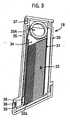
- the disposable strip cartridge 18includes a number of components designed to facilitate automatic, one-by-one dispensing of the test strips.
- the test strip cartridgeincludes a vial housing 30, a cartridge housing 31 including a stack of test strips 32, a cartridge cap 33 and a push-up or biasing mechanism 35.
- the cassette housing 31is disposed within the vial housing 30 in use, and that the cartridge cap 33 acts to close the vial housing.
- the push-up mechanism 35is also disposed within the vial housing.
- the stack of test stripscomprises about fifty test strips in vertical alignment.
- the test strip cartridge of the present inventionis not limited to a stack of fifty test strips and may include any number of stacked test strips.
- the push-up 35 mechanismbiases the test strip stack 32 towards the cartridge cap 33 such that when a foremost test strip 32a is removed from the stack, the remaining test strips in the stack advance by one. After the foremost strip is removed from the stack, the next strip in the stack moves up and is ready to be dispensed for a subsequent analysis.
- the push-up mechanismincludes a loader 34 pressing against the last strip in the stack 32 and a biasing element, illustrated as tensator 35A. As illustrated, the tensator 35A comprises a constant force clock spring that applies a constant pressure to the stack.
- the push-up mechanismmay also be provided with a non-return ratchet mechanism, or the like, active upon the loader 34 to prevent the loader 34 from moving back down within the cassette housing 31 and thus causing the top strip 32 to leave the ready-to-be-dispensed position.
- the ratchetmay take the form of an array of appropriately shaped protuberances disposed inside the cassette housing 31 and co-operative with protuberances upon the loader 34 exterior.
- the push-up mechanism 35further includes a tensator retainer 36 to secure a portion of the tensator to the cassette housing.
- the vial housing 30further includes notches 37 to releasably lock the cartridge in the modular housing of the meter. When loading the cartridge 18 into the meter the vial housing clicks unambiguously in place to ensure a precise fit.
- the cartridge cap 33includes a hermetic sealing element 38 which contacts the vial housing to form a seal to protect the test strips from humidity, which can damage the test strips and compromise test results.
- the sealcan be included in the vial housing where it meets the cap.
- the cartridge material itselfcan have desiccant properties, or desiccants can be disposed in the interior space of the vial. Any humidity that may migrate into the test strip vial is by these materials absorbed and neutralized.
- the cartridgeincludes on it a re-writable memory module such as an EEPROM chip.
- the electronics in the meterwill include means for interfacing with the memory module so that the meter can read from and write to the memory module.
- the memory modulewill contain a calibration code for the cartridge and will preferably contain a unique code for the cartridge and its expiry date. It may also contain compensation factors for analyses of different fluids (such as venous, arterial or neonatal blood or interstitial fluid), the number of strips in the cartridge and other relevant information.
- the electronics in the meterwill be set up to use any data stored in the memory module, in particular the calibration code.
- the electronicswill also be set up to write to the memory module such information as the number of strips used, the length of time the cartridge cap has remained open, the date of first opening the cap, the date and times of each test carried out and the result of the test.
- the cartridgemay alternatively include such data in other formats, such as in visible characters, as a bar code or as a resistor bridge circuit.
- the cartridge capis releasably locked into place on the cartridge by a cap retainer 39.
- the cartridge cap 33includes a "pop-up" feature.
- the cartridge cap 33is flexibly attached to the vial housing 30 by means of side supports, hinges, springs or another suitable mechanism. Pushing the cap retainer 39 releases the lock on the cartridge cap and allows the cap to pop up a predetermined amount, thereby allowing the foremost test strip 32a in the stack 32 to be fed to the sample-receiving position.
- the lockmay be released by pushing the locking member 39 such that it moves as a whole, thereby moving out of locking contact with the cap 33.
- the retainer or retainers 39may be bent away from the vial housing 30, by an outward pressure exerted by one or more arms 21a inserted between the retainer 39 and the vial housing 30 for example, thereby releasing their locking hold and allowing the cap 33 to "pop-up".
- the strip dispensing system 20 of Figure 1cooperates with the pop-up cartridge cap described above to push the foremost test strip of a test strip stack into the feeding channel 19 in order to position the test strip in the sample-receiving position with its sample-receiving area in close and precise proximity to a puncture site.
- the strip dispensing system 20comprises a multi-function handle 21.
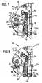
- Figure 6is a view of the integrated meter in an idle position.
- Figure 7illustrates the integrated meter when the multi-function handle is depressed.
- the multi-function handle 21comprises a lever 21a (see also Figures 31 to 34 ) and when a user depresses the lever, the lever disengages the locking mechanism on the cartridge cap 33.
- a cap opening spring 40 inside the handle lever 21pushes on the cap retainer 39 to release the cap 33 from the cartridge body and expose the slider slot behind the foremost test strip within the test strip cartridge.
- the handle lever 21aactuates a slider 41, which slides behind the foremost test strip and pushes the foremost test strip into the feeding channel 19 of the meter 10.
- the slideris a rotating flexible slider 41 and the drive element for the slider 41 includes a device, illustrated as a ratchetwheel in cooperation with a cog 42, to ensure that the foremost test strip is completely pushed into the feeding channel before another test strip can be dispensed.
- the slider 41only returns to its original position when the foremost test strip has been properly and accurately placed into the feeding channel and is in the sample-receiving position.
- any suitable mechanismmay be utilized for forwarding a test strip into a feeding channel and ensuring that the test strip is entirely dispensed.
- the test stripOnce in the feeding channel, the test strip is positioned to receive a blood sample for analysis.
- the userreplaces the cartridge cap 33 to re-seal the cartridge.
- closing the cartridge cap 33ejects the used test strip from the meter 10. This may be achieved by a contoured protrusion 33a from the cap 33, as shown in Figures 31 to 34 .
- the protrusionmay be in abutment with the rear of the in use strip or may be brought into abutment therewith during closing of the cartridge cap 33.
- the protrusionis contoured to progressively force the strip out of its sample-receiving position as the cap 33 closes, thereby ejecting the used strip and clearing the way for a new strip to be loaded during the next operation of the apparatus.
- the multi-function handle 21further includes a cocking lever 43 for arming the drive train 14 of the meter 10 when the handle is depressed.
- the multi-function handlefurther operates to switch on the electronics (not shown) of the meter 10 to prepare the meter for analysis of a prospective blood sample.
- the electronicsinclude a strip detector for detecting the presence of a test strip in the feeding channel. Thus, when the strip detector detects a strip in proximity to the lancing site, the electronics switch on.
- the strip dispensing system 20is designed to ensure that only one test strip is loaded at a time.
- the strip dispensing system 20includes a deviator 44 in co-operation with the slider 41.
- the strip dispensing system 20allows only one test strip to be forwarded at a time.
- the deviator 44automatically rotates into a position to deflect subsequent attempts to load an additional test strip into the feeding channel.
- the release of the cartridge cap caused by depression of the handleallows the deviator to rotate once the slider is moved back to its idle position. After forwarding one test strip, the slider route is deviated inside the cartridge cap 33, rather than through the test strip cartridge and into the feeding channel of the meter 10.
- the deviatorrotates back and resets the strip dispensing system to dispense a new strip.
- additional squeezing of the handle 21only serves to cock the lancet assembly 14 and does not load another test strip into the channel.
- the strip dispensing system 20allows several cocking and lancing attempts using the same test strip. This feature is particularly useful if the lancet is accidentally discharged or if the lacing action does not generate a sufficient amount of blood. In this case, the lancet assembly can be re-cocked without wasting a test strip.
- test strip cartridge 18 and the strip dispensing system 10co-operate with the lancet assembly illustrated in Figure 1 to efficiently and less painfully obtain and analyze a blood sample from a user.
- squeezing handle 21simultaneously cocks the lancet assembly and forwards a test strip from the cassette into the feeding channel 19.
- the lancet assemblyis in a neutral position prior to sampling.
- the drive train 14 of the lancet assemblycomprises a drive tube, a lancet holder slidably mounted in the drive tube for holding the lancet 13, a first spring for urging the lancet holder forward, a second spring for retracting the lancet 13 after the lancet punctures the skin, a trigger button 15 and a depth adjuster knob 17.
- the lancet assemblyfurther includes a lancet cap 16 having an aperture for guiding the lancet 13 through the aperture to the skin of a user and for shielding the lancet when not in use. Initially, the foremost test strip 32a within the test cartridge is also in a neutral position.
- the first springis a hard spring and the second is a soft spring.
- the residual momentum of the lancetsupplied by the first spring upon urging forward the lancet, causes the compression of the second spring. This compression begins when penetration of the skin by the lancet occurs. Once the force of the second spring on the lancet outweighs the residual momentum, the second spring causes the retraction of the lancet.
- the cocking lever 43retracts the drive tube to arm the lancet assembly, while simultaneously the test strip is fed through the feeding channel 19 and into the sample-receiving position within the lancet cap 16.
- the test stripis precisely located relative to the lancet 13.
- the userpresses the lancet cap 16 against a body part, such as a finger or arm, and depresses the trigger button 15 to allow the lancet assembly to drive the lancet tip into the skin, in close proximity to the sample-receiving area of the test strip.
- the lancet assemblysubsequently retracts the lancet tip from the skin.
- the pressure ringsqueezes the skin to maximize the quantity of blood formed from a puncture. Once the drop of blood is large enough, it will touch the sample-receiving area of the strip and will be wicked into the strip.
- the test stripautomatically directs the blood sample to an analysis portion and the analysis of the blood sample begins automatically.
- the usermay remove the lancet cap 16 and the lancet 13 from the lancet holder. The user may then discard the lancet 13, if desired.
- alternate lancet assembliesmay be utilized in accordance with the teachings of the present invention.
- the present inventionis not limited to the dual-spring drive train of the illustrative embodiment of the invention.
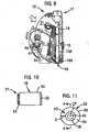
- FIGS 10 through 27illustrate different embodiments of the design for the lancet cap 16 of the present invention.
- the cap 1.6 for the integrated meter 10includes a cap body 50 having a proximal end 51 for connecting to the housing 11 of the lancing device and a contact ring 52 attached to the distal end of the cap body.
- the contact ring 52includes an aperture 45 for a portion of the lancet 13 of the lancing device to pass therethrough.
- the contact ring 52has a multi-contoured surface 53 oriented generally about an axis distinct from the axis of motion of the lancet 13. The multi-contoured surface is designed to pressure the dermal tissue to facilitate expression of a fluid sample after lancing the dermal tissue.
- the cap body 50can include a connector 54 for removably and replaceably connecting the proximal end of the cap body to the housing 11 of the integrated meter 10.
- the connector 54preferably is threaded to mate with corresponding threads provided in the housing 11 of the device 10.
- the connector 54can be sized and shaped to snap-fit to the housing 12.
- the cap 16can be permanently affixed to the housing 11, although it is preferable for the cap to be removably and replaceably connected to the housing 11.
- the cap body 50 and the contact ring 52can be constructed from plastic or other materials suitable for use in a medical instrument.
- the contact ring 52preferably has a multi-contoured surface 53 for contacting the dermal tissue both during lancing and during blood sample expression.
- the multi-contoured surface 53is oriented generally about an axis, indicated by line B in Figure 12 .
- the lancettravels along a first axis and the multi-contoured surface is oriented about a second axis perpendicular to the axis of motion of the lancet.
- the second axisis not limited to this preferred orientation and that any orientation distinct from the axis of motion of the lancet can be employed.
- the multi-contoured surface 53is designed to pressure the dermal tissue to maximize blood flow rate from the periphery of the pressured area to the center of the lancing site and to facilitate the expression of a blood sample for collection.
- the term multi-contoured surface as used hereincan comprise two or more surfaces oriented at distinct angles with respect to each other and with respect to a common axis.
- the multi-contoured surfacecan extend inwardly from a vertical wall, or can extend inwardly from a flat surface extending radially inwardly from the vertical wall.
- the multi-contoured surfacecan include any selected number of surfaces.
- the surfacecan be, according to one practice, non-planar.
- the multi-contoured surface 53is comprised of an outer radial portion 54 and an inner radial portion 56 proximate the opening 45.
- the outer radial portion 54is preferably oriented at a first angle C relative to the second axis B.
- the inner radial portion 56is preferably oriented at a second angle D, distinct from the first angle C, relative to the axis B.
- the outer radial portion 54 and the inner radial portion 56can have any selected surface feature or shape, e.g. can be linear, stepped or curved.
- the outer radial portion 54is generally linear from the perimeter 58 of the contact ring 52 to the intersection with the inner radial portion 56.
- the outer radial portion 54can be convex or concave in curvature.
- the inner radial portion 56is generally concave in curvature, but can also be linear or convex.
- the angle Ccorresponding to the slope of the outer radial portion 54, is in the range between about 5° and about 15°.
- the radial extent of the outer radial portion 54is preferably about 25% to about 75% of the total radius of the contact ring 52, as measured from the center point CP of the contact ring 52 to the perimeter 58 of the contact ring 52.
- the radial extent E of the outer radial portion 54is preferably about 50% of the total radius of the contact ring 52.
- the contact ring 52can be a separate, discrete component affixed to the cap body 50 or can be integrally formed with the cap body 50.
- the contact ring 52 of the cap 16is sized and dimensioned to be placed in intimate facing contact with the skin of the user. When placed thereagainst, the contact ring creates a pressure gradient that extends from the radial outer surface inwardly towards the opening 45. Specifically, when the skin is lanced by the lancet 13, the contact ring 52, which is disposed about the lancing site, creates a pressure gradient that urges fluid to flow toward the opening 45, as indicated by arrows 59.
- the pressure profile 61 created by the cap 16has pressure peaks 63 that coincide with the perimeter portion of the cap, or with the start of the multi-contoured surface 53.
- the pressureis a maximum at this portion since the cap contacts the skin of the user to a greater degree.
- the surfaces of the multi-contoured surfaceextend inwardly towards the opening 45 and away from the skin, the overall pressure decreases. This forms a pressure gradient that extends from the outermost portion of the cap 16 to the opening 45.
- the pressure profilewill change as a function of the configuration of the contact ring.
- Fig. 14illustrates another embodiment of the contact ring 52 of the cap 16 of the present invention.
- the illustrated contact ring 52'has an axially or vertically extending outer wall or perimeter 58' that terminates at a distal end 57.
- the distal end 57includes a first flat face portion 57A that is adapted to press against the skin of the user during use.
- the flat face portion 57Ais generally perpendicular to the perimeter portion 58'.
- the multi-contoured surface 53'extends radially inwardly from the flat face portion 57A towards the opening 45'.
- the multi-contoured surface 53'extends between the annular flat face portion 57A, as indicated by the designation L.
- the illustrated multi-contoured surface 53'includes two or more surfaces oriented relative to each other to form different, distinct angles.
- the multi-contoured surface 53'includes a pair of surfaces 65 and 67.
- the radially outer surface 65is oriented at a first angle relative to the axis B.
- the radially inner surface 67is oriented at a second angle relative to the axis B different from the first angle.
- the surfaces 65 and 67can have any selected shape or angle.
- the cap 16is connected to the housing 11 of the meter 10 and the dermal tissue is lanced by the lancet 13 passing through the opening 45 in the contact ring 52.
- the lancet 13is then withdrawn into the housing 11.
- the contact ring 52is pressed into contact with the dermal tissue proximate the lancing site causing blood to exit the lancing site and enter the cap 16 through the opening 45.
- Dermal tissueis "squeezed" into contact with the outer radial portion 54 and the inner radial portion 56 of the multi-contoured surface 53.
- the multi-contoured surface 53facilitates blood expression by increasing the pressure on the dermal tissue in contact with the perimeter 58 of the contact ring 52.
- the pressure on the dermal tissuedecreases as the slope of the outer radial surface 54 and the inner radial surface changes toward the opening 45. This inwardly extending pressure gradient is illustrated in Figure 13 .
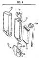
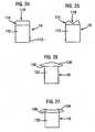
- FIG. 15 through 19An alternative embodiment of the cap is illustrated in Figures 15 through 19 in which a sleeve 70 is mounted about the cap body 50.
- the sleeve 70is movable generally along a first axis A, i.e. along the axis of motion of the lancet, and relative to the cap body 50.
- the sleeve 70comprises an annular collar 72 and at least two legs 74A and 74B that extend from the collar 72 in the direction of the first axis A toward the distal end of the cap 16.
- the legs 74A and 74Btaper from an increased width proximate the collar 72 to a decreased width proximate the contact ring 52.
- the legs 74A and 74Bare arcuate in cross-section and encompass only a portion of the circumference of the contact ring 52.
- the legs 74A and 74Bare preferably symmetrically disposed about the circumference of the contact ring 52.
- additional legscan be added without departing from the present invention.
- the legsneed not be positioned symmetrically about the contact ring 52.
- the sleeve 70is preferably slidable along an axis parallel to the first axis A, as indicated by arrow T in Figure 15 .
- a longitudinally extending slot 76can be formed in one or both of sides of the cap body 50.
- a protruding guide member 78can be formed in one or both of the legs 74A and 74B.
- the guide member 78is sized and shaped to slide within the slot 76 and inhibits lateral motion of the sleeve 70 relative to the cap body 50.
- the slot 76can be formed in one or more of the legs 74A and 74B and the guide member 78 can be formed on the cap body 50.
- a spring 79 or other biasing mechanismcan be provided to bias the sleeve 70 toward the distal end of the cap 10.
- the sleeve 70allows the user to maintain a portion of the lancing device, the legs 74A and 74B of the sleeve 70, in contact with skin when the cap 16 and the contact ring 52 are removed from contact with skin, as illustrated in Figure 17 .
- the legs 74A and 74Ballow the user to maintain the opening 45 in alignment with the lancing site when the contact ring is returned into contact with dermal tissue, as illustrated in Figure 18 .
- the legs 74A and 74Bcan be spaced apart a distance sufficient to allow a finger 80 of the user to fit between the legs 74A and 74B.
- the surface 77 connecting the two legs 74A and 74Bcan be curved, and are preferably parabolic in shape, to further fitting of the user's finger 80.
- the legs 74A and 74B, as well as the sleeve 70can be constructed from a flexible, resilient material, such as a flexible plastic.
- the preferred material of choiceis ABS plastic.
- the user's finger 80can be positioned between the legs 74A and 74B when the sleeve 70 is positioned beneath the cap 16.
- the legs 74A and 74Bcompress the user's finger therebetween to pinch or squeeze the dermal tissue.
- the user's fingercan then be lanced and the compression of the user's finger by the legs 74A and 74B can facilitate the expression of blood from the lancing site.
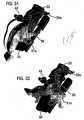
- FIG. 20 to 23Alternate embodiments of the cap are illustrated in Figures 20 to 23 , in which the contact ring 52 is designed for lancing the sharp curve (or side) of the fingertip, as well as the ventral side of the fingertip.
- FIGS 20 and 21illustrate another embodiment of the lancet cap suitable for use with the present invention.
- the cap 16includes a cap body 91 having a proximal end 96.
- a contact ring 95is attached to the distal end 93 of the cap body 91.
- An opening 90is provided in the contact ring 95 to allow a portion of the lancet 13 to pass through to effect puncturing of the fingertip.
- the illustrated cap body 91can include a connector 94 for removably and replaceably connecting the proximal end 96 of the cap body 91 to the distal end of the housing 11 of the device 10
- the connector 94can be sized and shaped to fit the housing 11.
- the lancet cap 16can be permanently affixed to the housing 11 although it is preferable that the lancet cap 16 be removably and replaceably connected to the housing 11.
- the contact ring 95preferably employs a pair of pressure wings 92 sized and dimensioned to accommodate the sharp curve of the fingertip therebetween.
- the pressure wings 92thus form a recess 97 for accommodating the finger of the user. This applies the correct amount of pressure to allow for the expression of blood.
- pressure wingsextend radially outward and away from the contact ring for contacting the fingertip both during lancing and during blood sample expression.
- the pressure wings 92constitute a multi-contoured surface that extends from the outer periphery of the body 91 to the opening 102.
- the multi-contoured surface 98is designed to pressure the fingertip to maximize blood flow rate from the lancing site and to facilitate the expression of blood for sample collection.
- the illustrated multi-contoured surface 98comprises two or more non-planar surfaces disposed at distinct angles relative to each other and with respect to a common axis.
- the pressure wings 92 that constitute the multi-contoured surface 98is comprised of a radial outer portion 98A and a curved radial inner portion 98B proximate to the opening 102.
- the transition point between the surfaces 98A and 98Bcan be arcuate, rounded, or sharp.
- the lancet cap 16 illustrated in Figures 20 and 21is connected to the housing 11 of the meter 10 of the present invention, and the fingertip of the user is placed in the recess 97 formed by the pressure wings 92.
- the lancet 13 of the deviceis deployed and passes through the opening 102 in the contact ring 95 to pierce the skin.
- the contact ring 95is pressed into contact with the fingertip proximate to the lancing site to express blood.
- the multi-contoured surfacefacilitates blood expression by creating a pressure gradient that extends radially inwardly towards the opening 102.
- Figures 22 and 23illustrate another embodiment of the lancet cap of the integrated blood sampling and testing meter according to the teachings of the present invention.
- the lancet cap 16includes a contact ring 105 attached to the distal end 107 of the cap body 104.
- An opening 101 formed in the contact ring 105allows a portion of the lancet 13 to pass therethrough to create a puncture on the ventral side of the fingertip.
- the illustrated contact ring 105has a multi-contoured surface 106 that extends from the periphery of the cap body 104 to the central opening 101.
- the multi-contoured surface 106can include two or more surfaces disposed at distinct angles relative to each other and with respect to a common axis.
- the illustrated multi-contoured surface 106is comprised of an outer radial portion 106A, a middle portion 106B, and an inner radial portion 106C disposed proximate to the opening 101.
- the outer, middle and inner radial portions of the capcan have any selected surface feature or shape, e.g., can be linear, stepped, or curved.
- the transition points between each surface 106A, 106B and 106C of the multi-contoured surfacecan have rounded, arcuate, or sharp surface features.
- the lancet cap 16When in use, the lancet cap 16 is connected to the housing 11 of the meter 10 of the present invention and is placed in intimate facing contact with the ventral side of the finger which is lanced by the lancet 13 passing through the opening 101 in the contact ring 105. The lancet 13 is withdrawn into meter 10. The fingertip is squeezed into contact with the outer radial portion 106A, middle radial portion 106B, and inner radial portion 106C of the multi-contoured surface 106. The multi-contourrsurface 106. facilitates blood expression by creating a pressure gradient that extends radially inwardly toward the opening 101 from the perimeter of the contact ring 105 or cap body 104.
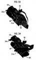
- FIGS 24 and 25illustrate another embodiment of the lancet cap for use at multiple different lancing sites according to the teachings of the present invention.
- the illustrated lancet cap 16includes a cap body 112 that terminates at a contact ring 114 mounted at a distal end.
- the distal end 115 of the cap 16can couple to the housing 11 via any suitable structure.
- the contact ring 114 of the cap 16can include, if desired, a multi-contoured surface 118 having a plurality of surfaces oriented at angles relative to each other.
- a central openingcan also be formed therein.
- the contact ringcan be a unitary structure with nominal surface features formed therein.
- the illustrated contact ring 114is preferably formed of a deformable, resilient, flexible material that is capable of conforming to the shape of the body region of the user placed in contact therewith.
- the contact ringcan be preferably formed of a rubber material, polyurethane, latex or other flexible material.
- the cap body 112can also be formed of any suitable transparent or translucent material, such as clear or transparent plastic, to enable the user to view the expressed blood. Alternatively, the cap can be formed of a non-transparent material.
- the contact ring 114can be disposed in a rest position, shown in Figure 24 , when not in contact with a lancing site, and hence no shape is imparted to the ring.
- the contact ringWhen placed in contact with the lancing site, such as the ventral side of a finger, or any other suitable portion of the finger, the contact ring conforms to the shape of the lancing site, as illustrated in Figure 25 .
- the lancet cap 16 of the integrated testing meter of the present inventioncan include a cap body 132 that has mounted thereto a deformable contact ring 134.
- the illustrated contact ring 134has edge portions 136 that extend over or outwardly from the perimeter of the cap body 132.
- the contact ringcan include, if desired, a multi-contoured surface having a plurality of surfaces oriented at angles relative to each other. A central opening can also be formed therein.
- the contact ringcan be a unitary structure with nominal surface features formed therein.
- the contact ringcan be preferably formed of rubber material, polyurethane, latex or other flexible material.
- the contact ring 134can be disposed in a rest position, shown in Figure 26 , when not disposed in contact with a lancing site, and hence no shape is imparted to the ring.
- the contact ring 134conforms to the shape of the lancing site, as illustrated in Figure 27 .
- the overhanging portions of the deformable contact ringcan 'flip' over and extend along the outer surface of the cap body 132 so it can be used on a flatter skin area, such as the forearm.
- the cap body 132can include a connector for removably and replaceably connecting a proximal end of the cap body 132 to the housing 11.
- the lancet cap 16can be permanently affixed to the housing 11.
- the lancet cap 16is removably and replaceably connected to the housing 11 of the integrated testing meter 10.
- the lancet cap 16 for use with the integrated sampling and testing meter of the present inventionis not limited to the illustrative embodiments described above. Those skilled in the art will recognize that a certain changes may be made to the lancet cap construction without departing from the scope of the invention.
- a significant feature of the integrated meter of the present inventionis that the strip dispensing system automatically and accurately positions the sample-receiving area of a test strip in close proximity to the puncture site formed by the lancet in order to provide a sufficient blood sample with a minimal puncture wound. Puncturing very accurately and in a defined proximity to the sample-receiving area of the test strip eliminates transfer of the sample by the user.
- the test stripwicks the blood sample directly from the puncture, allowing the use of low volume blood samples for analysis.
- the test stripis positioned to automatically and efficiently direct the sample to a defined area of the test strip for analysis.
- the strip dispensing system and the feeding channelco-operate with the lancet assembly to position the sample-receiving area of the strip about one millimeter away from the puncture site.
- the precisely controlled distance between the puncture and the sample-receiving area of the test stripdefines a minimal drop size required to be formed for analysis.
- the drop of blood formed by the puncturegrows to about 0.8 millimeter radius (about one microliter in volume)
- the droptouches the sample-receiving area of the test strip.
- the test stripprovides a capillary force to wick the blood drop into the test strip.
- the described arrangementefficiently conveys a sample from the skin to a precise position on the test strip with little or no loss.
- the test stripis flexible to accommodate deep and superficial bulging of the skin formed by the squeezing of the skin by the pressure ring in the lancet cap.
- the test stripis precisely positioned above the puncture site, in the lancet path, so that the lancet first pierces the wicking element of the test strip, then pierces the skin.
- the feeding channel 19 of the integrated sampling and testing device of the present inventionincludes a step 60, illustrated in Figure 28 .
- the step 60locks the strip and prevents the strip from reversing and moving back into the test strip cartridge 18.
- the walls of the feeding channelfurther provides lateral alignment of the strip.
- the electrical contacts 22 connected to the electronics in the devicemay be spring biased or otherwise arranged to lock the test strip into place behind the step.
- the cartridge capmay also include a strip ejection ramp to push the test strip out of the feeding channel when the cap is closed.
- the strip ejection rampmay be integral with the cartridge cap or removably connected to the cartridge cap.
- the lancet needle and the lancet assemblyprovides an accurate puncture site with little variation to ensure a precise relationship between the sample-receiving area of the test strip and the puncture site.
- the lancetis ground to center the point on the tip of the lancet.
- the lancet needleis ground at the edge, as with current lancets.
- the lancetis then positioned in plastic, such that the pointed tip is located in a fixed position in the center of the plastic.
- the puncture siteis precisely fixed, independent of the orientation of the drive train, and/or vibrations of the drive train.
- the lancet capfurther includes an alignment feature to control wobbling or vibration on the front end of the drive train.
- the lancet capincludes a plurality of alignment fins (not shown) disposed about the base of the lancet to secure the lancet. In this manner, the total variability of the puncture site is minimized.
- Figure 29illustrates a test strip design suitable for use in the present invention.
- the test stripmay utilize A-strip technology, membrane strip technology or other test strip designs known in the art for electrochemical or photometric analysis of a fluid.
- the test strip 32aincludes, as its sample-receiving area, a channel entrance 141 for directing a blood sample to an analysis portion of the strip.
- the test stripessentially comprises an electrochemical cell, including one or more working electrodes 142 which convert a chemical change produced by a reaction of glucose or other analyte in the blood sample to a current.
- the test stripfurther includes a reference electrode 143 as a standard to measure the potential of the working electrodes.
- Leads 144connect the electrodes to contact bars 145 configured to connect with the electrical contacts 22 of the integrated testing meter.
- the test stripthus generates a signal indicative of the level of glucose or other analyte in the blood and transmits this signal to the electronics of the device for processing.
- Figure 30shows a schematic representation of the electronics incorporated in the integrated meter of the present invention.
- the electronicsreceive a signal from the electrical contacts, process the signal and transmit instructions for an appropriate display to the display of the device.
- input signals related to the electrochemical analysis of the sampleare provided from the test strip to a signal processing system.
- the signalsare transmitted via analog circuitry to a processor, which performs data analysis.
- the processorprovides a signal to a display driver connected to an output display.
- the processormay also provide a signal to an alarm generator.
- the display and the alarm generatortogether constitute the output portion of the device.
- the data analysis processoralso communicates with a memory module, such as an EEPROM, in which information, including calibration information and previous test results, may be stored.
- the electronicsfurther include a detector for sensing a strip in the feeding channel.
- the detectorcan be two contacts which are shorted by a conductive layer on a strip when the strip is in the sample-receiving position.
- the electronicsmay be designed to produce an audible beep or visible signal to indicate to the user that a sufficient sample has been obtained and that analysis is complete.
- the electronicsmay also read, store and/or display information regarding the date and time of testing, the condition of the strips, the number of strips remaining in the stack, a calibration code for the strips, the expiration date of the test strip cartridge, the battery power of the meter, and so on.
- test strip specific informationcan be read directly from the cartridge, for instance by use of bar codes, resistance bridges or memory modules, preferably rewritable memory modules.
- the electronicsare switched on when a user depresses the handle of the integrated testing meter, or when a test strip detector detects a loaded test strip in the sample-receiving position.
- the data on the cartridgeis read to ensure that the correct calibration code and other data are used to control the meter. This ensures that a correct test result can be obtained even if the cartridge has been changed.
- the electronicsare switched off when the user replaces the test strip cartridge cap and ejects the used test strip from the meter.
- the electronics in the meterare arranged to record the length of time between a strip reaching the sample-receiving position and its being ejected from the meter. This is a measure of the time the cap is open. If the total time the cap is open exceeds a predetermined value, the electronics may be arranged to provide an audible or visible warning signal. The electronics may also be arranged to provide such a signal, or to switch off the meter, if any single strip has remained in the sample-receiving position for longer than a predetermined time.
- the integrated meter of the present invention and its componentsprovide significant improvements to the detection and monitoring of glucose levels in the blood.
- the present inventionconsiderably reduces the pain and inconvenience associated with glucose monitoring.
- the inventionfurther improves the efficiency and accuracy of testing by providing an automated transfer and analysis of the sample.
- the inventionprovides an integrated testing meter with user-friendly, uncomplicated operation.
- the integrated testing meteris compact, ergonomically sound, discrete and adjustable to different users and body parts while simultaneously providing fast and accurate results.
- the present inventionachieves a reduction in the pain associated with testing in a number of ways. Shallower punctures of the skin can be used to achieve a sufficient blood sample, reducing painful deep punctures in sensitive body parts.
- the present inventiondoes not require large sample volumes for analysis.
- the pressure devicefor instance formed by the pressure ring on the lancet cap, provides a high yield from a small puncture.
- the integrated sampling and testing featurefurther ensures full usage of the obtained sample and limits "leftovers" on the skin. In current systems, complex and inaccurate sample transfer from a sampling point to a sample-receiving area on a test strip requires surplus sample due to poor utilization of an obtained sample drop.
- the present inventionremoves this inefficiency of transferring samples and provides optimal utilization of the obtained sample by automatically directing the sample to a precise location on the test strip.
- Optimal utilization of the sample dropreduces the number of attempts needed to provide enough sample for efficient analysis, thus reducing the number of punctures required.
- the superficial puncturesreduce agitation of nerve endings in the skin and reduce pain in sensitive body areas.
- the variable depth of the lancet and the ability to test on a number of different body parts in addition to the fingerreduces the concentration and repetition of micro-traumata in a small area, which avoids the problems of tinting, itching, dried and callous skin areas caused by such micro-traumata.
- the integrated meter of the present inventionis able fully to exploit the technological improvements in strip design which allow the use of much smaller samples.
- Presently available stripsrequire only 1 to 3 ⁇ l of sample.
- Many usershave eyesight problems and cannot see well enough to be able to transfer such small volumes of sample accurately to the sample-receiving area of a strip.
- Such eyesight problemsare common complications of diabetes.
- the automatic collection and transfer of samples to the strip enabled by the present meteris a major advantage of the present meter.
- the small volume of blood or other bodily fluid expressed from the useris sufficient to accurately determine or monitor the presence or absence of an analyte, such as glucose.
- the present inventionfurther provides easy and uncomplicated operation.
- the use of the metersignificantly reduces the time and difficulty involved in sampling and testing blood.
- the integrated meteressentially provides three devices, a lancing device, a supply of test strips and a meter, within a singular compact housing. Further, the system is designed such that one-handed operation is possible, eliminating the need for a work space or a flat surface. The meter is not subject to human error and inefficiency.
- the integration of a disposable test strip cartridgemakes the loading of a test strip simple, accurate and easy. In current glucose monitoring systems a user requires two hands to load a strip into a glucose meter. However, with the meter of the present invention, the test strip dispensing system automatically loads a test strip in position to receive a blood sample.
- the present inventionalso reduces waste by efficiently utilizing available resources.
- the present inventionfurther protects against compromised test results due to contamination or an improperly calibrated glucose meter.
- the integrated meter of the present inventionsignificantly reduces the obstacles associated with frequent glucose monitoring.
- the present inventionpromotes frequent monitoring for diabetic individuals by providing a simple, efficient, fast and accurate integrated meter.
Landscapes
- Health & Medical Sciences (AREA)
- Life Sciences & Earth Sciences (AREA)
- Engineering & Computer Science (AREA)
- Biomedical Technology (AREA)
- Physics & Mathematics (AREA)
- Molecular Biology (AREA)
- Hematology (AREA)
- Biophysics (AREA)
- Pathology (AREA)
- General Health & Medical Sciences (AREA)
- Veterinary Medicine (AREA)
- Surgery (AREA)
- Animal Behavior & Ethology (AREA)
- Heart & Thoracic Surgery (AREA)
- Public Health (AREA)
- Medical Informatics (AREA)
- Dermatology (AREA)
- Chemical & Material Sciences (AREA)
- Vascular Medicine (AREA)
- Biochemistry (AREA)
- Urology & Nephrology (AREA)
- Pain & Pain Management (AREA)
- Food Science & Technology (AREA)
- Medicinal Chemistry (AREA)
- Analytical Chemistry (AREA)
- Optics & Photonics (AREA)
- General Physics & Mathematics (AREA)
- Immunology (AREA)
- Measurement Of The Respiration, Hearing Ability, Form, And Blood Characteristics Of Living Organisms (AREA)
- Investigating Or Analysing Biological Materials (AREA)
- Investigating Or Analyzing Materials Using Thermal Means (AREA)
- Investigating Or Analysing Materials By Optical Means (AREA)
- Analysing Materials By The Use Of Radiation (AREA)
Abstract
Description
- The present invention relates to an integrated sample testing meter for use in sampling and analyzing analytes, particularly glucose, in fluids such as blood or interstitial fluid.
- Glucose monitoring is a fact of everyday life for diabetic individuals. The accuracy of such monitoring can literally mean the difference between life and death. Generally, a diabetic patient measures blood glucose levels several times a day to monitor and control blood sugar levels. Failure to test blood glucose levels accurately and on a regular basis can result in serious diabetes-related complications, including cardiovascular disease, kidney disease, nerve damage and blindness. A number of glucose meters are currently available which permit an individual to test the glucose level in a small sample of blood.
- Many of the glucose meter designs currently available make use of a disposable test strip which, in combination with the meter, electrochemically or photometrically measures the amount of glucose in the blood sample. To use these meters, the user first punctures a finger or other body part using a lancet to produce a small sample of blood or interstitial fluid. The sample is then transferred to a disposable test strip. The inconvenience of taking several measurements a day, as well as the pain inflicted by currently available lancets, often discourage disciplined and frequent testing.
- While the fingertip is generally used for sampling blood, due to the rich capillary bed of the skin of the fingertip, the fingertip is also particularly sensitive to pain, due to a rich supply of pain receptors in the finger tip as well. When a puncture is too deep, too close to a recent puncture or not deep enough and requires an additional puncture, the pain increases significantly. Pain may also be increased if the lancet penetrates slowly or is withdrawn slowly. Furthermore, the user may be forced to make a larger puncture than is necessary to form a sufficient amount of blood, due to losses during the transfer between the puncture site and the test strip.
- The process of measuring blood glucose levels requires several steps and several different accessories, including a lancing device, a lancet, a supply of test strips and a glucose meter. Each accessory has a different function. The user must have a flat surface available to unpack and lay down the accessories within easy reach. This, by itself, poses a challenge for those who need to take measurements while participating in outdoor activities. Flat surfaces are often not available and this can discourage a person from taking a measurement. This can be disadvantageous because blood glucose levels may change significantly during an outdoor activity.
- Even if a user can find a flat surface, the user has to carry out the following steps. The user: charges the lancing device with a fresh lancet; opens a vial of strips; removes a strip; inserts the strip into the meter; re-closes the vial; checks for the correct calibration code on the meter; picks up the lancing device; lances the skin of the finger or other body part; lays down the lancing device; squeezes or massages the finger to yield an adequate blood sample; transfers the sample to the test strip for analysis; waits for the meter to analyze the sample; removes the strip from the test meter; discards the strip; and finally re-packs all of the accessories. As set forth above, the standard procedure for taking a glucose measurement requires the use of multiple, separate components and the execution of a number of steps requiring manual user intervention.
- Generally, the user is required to transfer a small volume of sample to a sample-receiving area on the test strip. Generally, test strips are quite small and the sample-recciving area is therefore even smaller. This transfer step is a difficult task for many users. Moreover, there has recently been a trend towards the use of test strips requiring ever smaller amounts of sample. (This allows the use of smaller punctures and therefore less painful lancing.) However, the use of smaller samples increases the difficulty in transferring the sample to the sample-receiving area on the test strip. This is especially difficult for users with poor eyesight, a common complication for diabetics.
- The pain, inconvenience, cost, slowness, complexity and discreteness of taking a blood glucose measurement are barriers to the frequent monitoring of glucose levels.
- Patients often do not comply with doctor recommendations to frequently test glucose levels due to the numerous obstacles involved.
DE 19819401 discloses a testing meter with cartridge and automatic mechanism to bring the strip in the measuring position. - It is an aim of the present invention to provide, at least in part, a solution to the above problems.
- Accordingly, the present invention provides an integrated sample-testing meter comprising a single modular housing as defined in appended claim 1. Further preferred features of the invention are defined in subclaims 2-10.
- Additional features of the invention and related aspects of the invention are outlined as follows:
- The meter of the present invention preferably includes electrical or electronic circuitry for controlling its operation. Such circuitry may be hard-wired or may comprise a microcomputer or similar device. Such circuitry will in particular include all the components of the sensor and will be arranged to carry out the analysis of the sample.
- Preferably, the circuitry also includes a visual display unit from which the user can read out the results of any particular test. The display may also be adapted to provide a display of the data, as explained in more detail below.
- Preferably, the circuitry includes means, such as a touch sensitive display, a microphone and voice activated software or control buttons, for entering data into the meter.
- Preferably, the meter is arranged such that, in use, when strip is in the sample-receiving position, its sample receiving area is spaced from the puncture site by a distance of from about 0.4 mm to about 1.3 mm and preferably by a distance of about 0.7 mm to about 0.9 mm.
- The pressure device may comprise a pump adapted to apply a negative pressure to a volume in the meter having an aperture for location on the skin of the user.
- Preferably, however, the pressure device comprises a pressure ring arranged to be located, in use, on the user's skin and to apply pressure at the edges of the ring to increase the amount of fluid available at the centre of the ring.
- The pressure ring may be shaped to conform to the shape of the area of the skin to which it is to be applied. For instance, if the meter is intended for use on the forearm, the pressure ring will be generally planar. However, if the meter is intended for use on a finger, the pressure ring will be curved.
- Preferably, the pressure ring has a multi-contoured surface to increase the pressure gradient from the outside to the inside of the ring.
- Advantageously, the pressure ring is part of a lancet cap which covers the lancet in its retracted position. Preferably, the lancet cap includes a means, such as a side wall, which co-operates with the lancet drive train to ensure that the lancet travels along approximately the same path on each activation of the drive train.
- The lancet cap may be an integral part of the housing. Preferably, however, the lancet cap is detachably mounted on the housing. This may be achieved by use of screwthread or bayonet type fixings or by use .of a snap fit connection.
- If desired, the meter can include at least two interchangeable lancet caps, for instance a lancet cap for forearm use and a lancet cap for finger use.
- The lancet may be any of the types of lancet at present in use in the art. The term "lancet" includes finger-sticking devices of the type known in the art. Preferably, the lancet is removably attached to the lancet drive train so that the lancet can be disposed of after one or several uses.
- Preferably, the lancet drive train is spring driven. Alternatively, the lancet drive train is driven electromagnetically. The drive train is arranged such that, on actuation, the lancet moves to the extended position and is retracted.
- Preferably, the lancet drive train includes an adjustment screw which allows the user to set the extended position of the lancet. This enables the user to calibrate the operation of the meter such that his or her skin is punctured sufficiently to allow a large enough drop of fluid to form without causing too much pain.
- Advantageously, the operation of the adjustment screw is arranged such that the distance of travel of the lancet remains constant, however much the extended position of the lancet is changed. This ensures that the amount of pain experienced by the user does not increase disproportionately to the depth of puncture.
- Where the meter includes a lancet cap, it is preferable, as noted above, that the lancet cap provides a means for guiding the lancet drive train so that the lancet punctures ' the skin at approximately the same place on each actuation of the drive train.
- Advantageously, in such case, the lancet drive train is arranged such that the end of the lancet, in its extended position, extends to approximately the plane formed by the pressure ring or aperture in the housing which, in use, is placed on the user's skin.
- Preferably, the test strip cartridge comprises a cartridge housing defining a cavity configured to receive a stack of test strips, a partially detachable cartridge cap and a means for moving the stack of test strips towards the cartridge cap.
- The test strips used for some measurements are air-or moisture-sensitive. It is therefore preferred that the cartridge includes a seal for sealing the cartridge cap to the cartridge housing when the cartridge cap is fully engaged with the cartridge housing. The seal may be on the cartridge cap or on the cartridge housing. Further, the cartridge may be manufactured from a material having dessicant properties, or a dessicant may be contained within the cartridge.
- In use, upon activation of the meter, the cartridge cap is partially detached from the cartridge housing to allow the first test strip in the stack to be moved by the test strip dispensing system to the sample-receiving position. Once the measurement has been taken, the cartridge cap is preferably manually replaced on the cartridge housing to close the cartridge and seal its contents from atmospheric effects.
- Preferably, the cartridge has on it data relating to the calibration code for the strips in the cartridge. The data may be present as visually readable indicia. In this case, the meter must include means, as mentioned above, to allow the user to enter the calibration code into the meter.
- Preferably, however, the data on the cartridge are present in machine-readable format, for instance as a bar code or a resistance bridge circuit or stored in an electronic memory module.
- If the data are present as a bar code, the meter will include a bar code reader. This may be a scanning reader or a stationary reader. A scanning reader will be more complicated but can be used when the cartridge is fitted in the meter. A stationary reader is less complicated but can only be used as the cartridge is inserted into or taken out of the meter.
- If the data are present in an electronic memory module, this may comprise a read-only memory (ROM), or a rewritable memory, such as an EEPROM.
- Preferably, the data also include a unique number identifying the specific cartridge, the number of strips originally present in the cartridge, the expiry date for the cartridge, different calibration factors for different sources of fluid (neonatal, arterial or venous blood, for instance) and any other relevant information such as control solution range information, preferably in machine-readable format, to assist in operation of the meter.
- Where the memory module on the cartridge is rewritable, the meter may be arranged to write back into the memory module information such as the number of strips used, the date the cartridge was first used, the length of time the cartridge has remained open and the date, time and result of each test that was carried out with a strip from the cartridge.
- Preferably, the test strip dispensing system includes a slider adapted to engage with only one of the test strips in the cartridge and move it to the sample-receiving position.
- Advantageously, the meter includes a feeding channel which receives the strip from the cartridge and guides it to the sample-receiving position.
- Preferably, the feeding channel includes a step arranged such, when the strip has been moved past the step, the strip drops, or is forced, into the step, thereby preventing the strip from moving back towards the cartridge.
- Preferably, the strip is forced into the step by springs located on the meter. Advantageously, the springs are also electrically conductive and are arranged to make electrical contact with electrodes or a conductive bar on the strip (see below).
- Preferably, the feeding channel is arranged such that the major plane of the strip, when in the sample-receiving position, is at an angle of from about 30° to about 60°, preferably about 45°, to the direction of movement of the lancet towards its extended position.
- Advantageously, the meter includes an ejection means for ejecting a used test strip from the mete once a test has been completed. Preferably, where the cartridge includes a cartridge cap, the ejection means is operated as the cartridge cap is closed.
- Preferably, the meter includes a deviator which prevents the test strip dispensing system moving a further test strip into the sample-receiving position while a first test strip is still in position. This is an advantageous feature as it allows the user to carry out a number of lancing operations with the same strip in position, since, in some cases, it takes a number of lancing operations, if necessary with adjustment of the lancet drive train, to produce a sufficiently large drop of fluid.
- Preferably, the deviator operates in conjunction with the cartridge cap. While the cartridge cap is partially detached from the cartridge housing, the deviator blocks the normal path for the test strip dispensing system, such as the slider, and causes it to enter the cartridge cap.
- Preferably, the meter includes a means for verifying that a strip is in the sample-receiving position. This may comprise a reflectance meter. Generally, test strips are more or less reflective than the surfaces of the feeding channel. Therefore, a change in reflectance will indicate that a test strip is in position.
- Preferably, however, the verifying means comprises an electrical system. At its simplest, each strip may have on it a conductive bar arranged to short out two electrodes on the meter. This arrangement is useful for strips arranged to carry out photometric measurements.
- Strips which are arranged to carry out electrochemical measurements already include electrode systems. Thus, the verifying means may include electrical contacts on the meter which contact the electrodes on the strip. Advantageously, as noted above, the electrical contacts on the meter are spring loaded and are positioned to force the strip into the step in the feeding channel.
- Advantageously, the verifying means is also used to activate fully the circuitry in the meter. The meter may normally be in a low power mode, where the only active circuitry is that used to control the verifying means. Once the verifying means has indicated that a strip is present, the meter can then automatically switch to high power mode where all its relevant circuits are functioning.
- Preferably, the verifying means is also arranged to start a timer in the circuitry of the meter. The timer is stopped by the ejection of a used strip from the meter, preferably by closure of the cartridge cap. This allows the circuitry to determine the length of time the cartridge has been open to the atmosphere. Advantageously the circuitry is arranged to sum the total time that the cartridge has been open and to produce a warning signal, such as an audible tone or a visible signal, if the total exceeds a pre-set maximum.
- Preferably, the circuitry in the meter also counts the number of strips dispensed from each cartridge. Advantageously, the circuitry is designed to provide a warning signal, such as an audible tone or a visible signal, when the number of strips remaining the cartridge is low.
- As noted above, the cartridge preferably includes a rewritable memory module and the circuitry in the meter is arranged to write back to the cartridge memory module useful information, such as the number of strips remaining in the cartridge and the length of time the cartridge has been open to the atmosphere. The rewriting function is particularly useful where a user is likely to be away from his normal environment for a length of time which would require the use of more strips than are present in a cartridge. In such cases, a user is likely to remove the old cartridge and insert a new, full cartridge. Once the new cartridge has been used up, the user may insert the old cartridge, even if it is out of date. As long as the meter can read the data on the old cartridge, it will be able to decide whether use of the old cartridge should be allowed.
- Moreover, the provision of a rewritable memory module enables other possible uses. For instance, data on time and date of use and result of measurement may be written into the cartridge's memory module. The used cartridge could then be returned to the user's health care provider who could then study: the data to determine whether the user is complying with his treatment and monitoring regime. Alternatively, the used cartridges could be returned to the manufacturer to enable a general study of use to be carried out.
- Preferably, the meter is activated manually by use of a single movement, for instance of a multi-functional handle assembly carried by the housing. The handle assembly may include a lever pivoted to the housing.
- Preferably, the actuation of the handle assembly cocks the lancet drive train and moves a single test strip into the sample-receiving position. The movement of the handle assembly may also activate all the meter's circuitry.
- The lancet drive train may be fired either by further movement of the lever or, preferably, by actuation of a trigger.
- It can thus be seen that the use of the integrated sample testing meter of the present invention can be very simple. If desired, the user can replace an existing lancet with a new one. The meter can then be cocked by use of the handle assembly. This also moves a strip into the sample-receiving position. Movement of the lever or receipt of a strip in the sample receiving position also activates all the meter's circuitry. Then, the user only has to place the appropriate part of the meter, such as an aperture or the lancet cap, on his skin and activate the trigger.
- If the first activation of the trigger does not cause the production of a sufficiently large drop of fluid, the meter can be cocked, positioned and fired again, if necessary a number of times, without the need to insert a new strip.
- The presence of the pressure device ensures that, once a reasonable puncture is made, sufficient fluid will accumulate around the puncture so that it will contact the sample-receiving area of the strip and a sample will be taken onto or into the strip.
- Thus, the use of the meter of the present invention avoids most of the steps presently required and in particular avoids those steps where manual dexterity and good eyesight are advantageous.
- Preferably, the meter is adapted to produce and analyze a sample of blood or interstitial fluid, in particular to analyze a blood sample for glucose levels. Strips adapted to carry out such measurements are well known in the art. These may be electrochemical or photometric strips.
- Advantageously, the strips are adapted to carry out electrochemical analyses and the circuitry in the meter is arranged to contact the electrodes in such strips.
- Therefore, in a preferred embodiment the present invention provides an integrated blood glucose testing meter. The integrated meter of this aspect of the present invention allows for a simple, one-step glucose monitoring process, and significantly reduces the obstacles involved in frequent glucose monitoring. The integrated meter provides for the automated and precise dispensing and positioning of a test strip in repeatable close proximity to a lancet puncture site, automated transfer of a blood sample to the test strip and automated analysis of the blood sample after the test strip collects the sample from the puncture site.
- In accordance with another aspect of the present invention, there may be provided a disposable test strip cartridge adapted to be loaded into the meter of the present invention. The cartridge includes a cartridge housing defining a cavity configured to receive a stack of test strips, a partially detachable cartridge cap and a stack of test strips disposed in the cavity.
- According to another aspect, the present invention provides a multi-function handle assembly for the meter of the present invention. Preferably, the handle assembly comprises a lever. When a user depresses the handle assembly, the lever simultaneously cocks a lancing device and dispenses one test strip from the test strip cartridge into the sample-receiving position. The test strip is precisely positioned at a predetermined distance from the lancet.
- According to yet another aspect, the present invention provides a strip dispensing system for forwarding test strips from a test strip cartridge to the sample-receiving position in the meter of the present invention on a one-by-one basis. The strip dispensing system includes a slider for pushing a test strip from the cartridge to a feeding channel and a deviator for preventing a plurality of test strips from being positioned in the feeding channel at one time. The deviator diverts the slider inside the test cartridge cap when a test strip is positioned in the feeding channel.
- The present invention makes possible an integrated method of sampling and testing a blood glucose level or other analyte in a bodily fluid. Such an integrated method may comprise loading a test strip cartridge into an integrated testing meter, depressing a handle assembly on the testing meter to cock a lancing device and push a test strip into a sample-receiving position, pressing the integrated testing meter on the skin of a user and pressing a trigger of the testing meter to drive a lancet into the skin in order to form a drop of blood or other fluid on the skin surface. The test strip absorbs a required amount of blood or other fluid for an automated analysis of the sample by the integrated testing meter.
- These and other features and advantages of the present invention will be more fully understood by reference to the following detailed description in conjunction with the attached drawings in which like reference numerals refer to like elements through the different views.
Figure 1 is a perspective view of an integrated blood and testing meter according to the present invention.Figure 2 is a plan view of the exterior of the integrated meter ofFigure 1 .Figure 3 is a partially cut-away perspective of a disposable test strip cartridge that mounts in the meter ofFigure 1 .Figure 4 is an exploded view of the components of the disposable test strip cartridge ofFigure 3 .Figures 5a, 5b and 5c illustrate a "pop-up" feature of the cap of the disposable test strip cartridge.Figure 6 is a partial cut-away view of one embodiment of the integrated meter in an idle position.Figure 7 illustrates the integrated meter ofFigure 6 when the multi-function handle is depressed.Figure 8 illustrates the integrated meter ofFigure 6 when the multi-function handle is released.Figure 9 illustrates the integrated meter ofFigure 6 when the multi-function handle is pressed when a test strip is loaded.Figure 10 is a side view of a lancet cap suitable for use with the meter of the present invention.Figure 11 is an end view of the lancet cap ofFigure 10 .Figure 12 is a side elevational view in cross section along line 4-4 ofFigure 11 , illustrating the contact ring of the cap ofFigure 10 .Figure 13 is a graphic representation of the pressure profile created by the cap ofFigure 10 .Figure 14 is a cross-sectional view of an alternate embodiment of the contact ring of the lancet cap for use with the meter of the present invention.Figure 15 is a side elevational view of an alternative embodiment of a lancet cap for use with the meter of the present invention, illustrating a sleeve positioned about the cap.Figure 16 is an end view of the lancet cap ofFigure 15 .Figure 17 is a side elevational view of the lancet cap ofFigure 15 , illustrating the cap displaced from the skin.Figure 18 is a side elevational view of the lancet cap ofFigure 15 , illustrating the cap in contact with the skin.Figure 19 is a front elevational view of the cap ofFigure 15 .Figure 20 is a front elevational view of another embodiment of a lancet cap for use with the meter of the present invention.Figure 21 is an end view of the cap ofFigure 20 .Figure 22 is a front elevational view of another embodiment of a lancet cap for use with the meter of the present invention for lancing the ventral side of a fingertip.Figure 23 is an end view of the lancet cap ofFigure 22 .Figure 24 is a side view of an alternate embodiment of a lancet cap for use with the meter of the present invention formed of a flexible material and disposed in a rest position.Figure 25 is a side view of the lancet cap ofFigure 24 when the contact ring of the lancet cap contacts a lancing site.Figure 26 is a side view of an alternate embodiment of a lancet cap for use with the meter of the present invention formed of a deformable, flexible material and disposed in a rest position.Figure 27 is a side view of the lancet cap ofFigure 26 when the contact ring of the lancet cap contacts the lancing site.Figure 28 illustrates the feeding channel of the integrated meter according to the present invention.Figure 29 is a schematic view of a test strip design suitable for use in the present invention.Figure 30 is a schematic representation of the electronics which can be incorporated in an integrated meter in accordance with the present invention.Figure 31 illustrates an alternative mechanism for providing a "pop-up" feature of the cap of the disposable test strip cartridge, with the cap closed.Figure 32 illustrates the mechanism ofFigure 31 with the cap open.Figure 33 illustrates the mechanism ofFigure 31 from an opposite side.Figure 34 is an opposite side view of the mechanism ofFigure 31 with the cap open.- The present invention provides an integrated meter for sampling and analyzing a sample of bodily fluid, such as blood, including a disposable test strip cartridge having a stack of test strips disposed therein. The present invention facilitates the monitoring of, for instance; blood glucose levels by integrating into a single meter the steps involved in sampling and analyzing blood into a simple process employing a single meter.
- The present invention will be described below relative to an illustrative embodiment. Those skilled in the art will appreciate that the present invention may be implemented in a number of different applications and embodiments and is not specifically limited in its application to the particular embodiment depicted herein.
- The present invention will be discussed below in connection with sampling blood, although those of ordinary skill will recognize that other types of fluid can also be used.
Figures 1 and 2 illustrate an integrated blood glucose sampling andtesting meter 10 according to an illustrative embodiment of the present invention. This meter is designed to carry out electrochemical analysis of a blood sample. However, if desired, the same mechanical parts could be used in connection with photometric analyses. The sampling and testing meter comprises a modular housing 11 (shown inFigure 2 ) encompassing an integrated system for expressing and subsequently analyzing a sample. Themeter 10 includes a lancet assembly for puncturing the skin of a user to express a drop of blood on the surface of the skin. The lancet assembly includes alancet 13 and alancet drive train 14 for driving the lancet into and out of the skin. When cocked, a triggeringbutton 15 actuates the drive train.- A
lancet cap 16 is removably attached to thehousing 11 at the proximal end of thedevice 10 and includes an aperture to allow passage of thelancet 13 through thecap 16 and into the skin of the user. Thecap 16 can have a multi-contoured surface in order to promote, enhance or facilitate the expression of blood by pressing the device onto the skin. The lancet assembly further includes adepth adjustment knob 17 situated at the distal end of the drive train opposite the lancet. Rotation of the depth adjustment knob decreases or increases the puncture depth of the lancet. The depth adjustment knob regulates or adjusts the puncture depth in accordance with known techniques. - A
test strip cartridge 18 is loaded into themeter 10 and includes a stacked supply of test strips disposed within a cavity or hollow interior of the cartridge housing. The test strip cartridge is adapted to dispense individual test strips to a feedingchannel 19. The outlet of the feeding channel leads into the interior of the lancingcap 16, in precise and close proximity to the aperture through which thelancet 13 passes when puncturing the skin. In this manner, when the lancet punctures the skin and a drop of blood forms on the skin surface, the test strip is located in close proximity to the puncture wound to ensure that blood contacts the strip. Moreover, the precise positioning of the test strip adjacent the lancet ensures that only small volumes of blood are required, as the strip is able to touch and automatically wick up even a small drop of blood. - According to one practice, as illustrated in
Figures 7, 8 and9 , the housing includes aninternal wall 19A that defines the inner side of thelancet cap 16. According to an alternate embodiment, thehousing wall 19A can have a frusto-conical or funnel shape, or any other suitable shape, for precisely positioning the lancet relative to the test strip. - The lancet cap is precisely dimensioned such that the
lancet body 13A that carries thelancet 13 slidably passes through the cap. In this arrangement, thelancet 13 is precisely positioned at about the same location each time it is deployed. Correspondingly, each test strip is precisely positioned at about the same location each time one is moved from the cartridge to the sample-receiving position. - The terms "precise" and "precisely" are used herein to include positioning the puncture point of the
lancet 13 and the sample-receiving area of the test strip relatively close to each other in a repeatable manner. - The integrated meter of the present invention is able fully to exploit the technological improvements in strip design which allow the use of much smaller samples. Presently available strips require only 1 to 3 µl of sample. Many users have eyesight problems and cannot see well enough to be able to transfer such small volumes of sample accurately to the sample-receiving area of a strip. Such eyesight problems are common complications of diabetes. The automatic collection and transfer of samples to the strip enabled by the present meter is a major advantage of the present meter.
- It is thus possible to arrange the operation of the lancet and the pressure device to produce a puncture which allows a small, but sufficient, volume of blood to be expressed as a drop of the user's skin. Such a small drop will be able to contact the sample-receiving area of the test strip due to the precise positioning of the lancet and the test strip.
- The small volume of blood or other bodily fluid expressed from the user is sufficient to accurately determine or monitor the presence or absence of an analyte, such as glucose.
- The meter is arranged such that, in use, with the strip in the sample-receiving position, its sample-receiving area is separated from the puncture by between about 0.4 mm and about 1.3 mm, and preferably between about 0.7 mm and about 0.9 mm.
- Once the sample drop touches the sample-receiving area of the test strip, the test strip automatically directs the blood sample to the testing portion of the strip.
- The test strip cartridge comprises a replaceable and disposable portion of the sampling and testing meter. When the supply of test strips is depleted or expired, the user may remove the used
test strip cartridge 18 and insert a new test strip cartridge containing a fresh supply of test strips. The details of thetest strip cartridge 18 are described in depth below. - A
strip dispensing system 20 operates in co-operation with thetest strip cartridge 18 to dispense test strips one-by-one through the feedingchannel 19 and into the sample-receiving position to effect the sampling and analysis of a blood sample. According to the illustrated embodiment, when a user depresses or squeezes thehandle 21 of thedevice 10, thestrip dispensing system 20 pushes the foremost test strip in the stack out of the test strip cartridge and into the feeding channel. According to a preferred embodiment, handle 21 performs an additional function of simultaneously cocking the lancet assembly to prepare the lancet assembly for lancing the skin of a user when the user depresses or squeezes the handle. The workings of the strip dispensing system andmulti-function handle 21 are described in further detail below. - To enable electrochemical analysis of the sample, the meter further includes
electrical contacts 22 situated adjacent the feedingchannel 19 and configured to contact electrodes formed on the test strip. The electrical contacts connect to electronics (not shown) located within themodular housing 11 of the sampling and testing meter. The electronics are arranged such that, once thecontacts 22 contact the electrodes in the strip, the meter switches from "low" power made to "high" power mode. - The test strip generates electrochemical signals that are passed by the electrical contacts to the housing electronics. The electronics process the signal and calculate the glucose level or other electrochemically detectable analyte of the blood or other interstitial fluid that is sampled by the testing device. The electronics transmit instructions for an appropriate display or output regarding the analysis.
- The feeding
channel 19 has in it astep 60 located adjacent theelectrical contacts 22. Theelectrical contacts 22 are spring biased so that, once a test strip is in the sample-receiving position, theelectrical contacts 22 bear on the test strip and locate it securely in the step. In this manner, the strip is prevented from moving backward away from the sample-receiving position. - As illustrated in
Figure 2 , the integrated sampling andtesting meter 10 includes avisual LCD display 23 for displaying information related to the analysis of the sample. According to the illustrative embodiment, the information in the display includes a measured blood glucose level in a blood sample, as well as the time and date of the measurement. The display may also provide information regarding the number of test strips remaining in the test strip cartridge, the operating temperature, the expiration date of the test strip cartridge, instructions to the user and the like. According to one practice of the invention, test results are stored in memory in the meter and thedisplay 23 allows a user to view prior test results. - The meter also has on its outside buttons which can be used by the user to enter data into the meter's electronics. This may be achieved by using the buttons to navigate through one or more menus displayed on the
display 23. - To measure blood glucose levels with the
integrated meter 10, a user first depresses thehandle 21 to simultaneously cock the lancet assembly and automatically open the test strip cartridge and to advance a test strip from the cassette to the feedingchannel 19. The user then presses themeter 10 against a body part, such as a finger or forearm, such that the skin of the user contacts the lancingcap 16. When a user pushes thetrigger button 15, the lancet assembly fires thelancet 13 into the skin a predetermined depth and at a precise location. The lancet assembly immediately retracts the lancet from the skin. - The lancing
cap 16 includes a pressure ring (not shown) so that, as the meter is pressed onto the skin after the lancing has taken place, a drop of blood of the required size forms on the user's skin. As the blood drop grows, the blood contacts the sample-receiving area of the test strip and capillary force absorbs blood into the strip for analysis. The user holds the meter firmly against the skin until a sufficient amount of blood is absorbed into the test strip, generally for about 3 to 10 seconds. According to one practice, themeter 10 produces an audible or visible signal to the user indicating that a sufficient blood sample has been collected and that analysis has begun. The user then removes the meter from the skin and the electrochemical analysis of the sample continues until the result is displayed. - Referring to
Figures 3 and4 , thedisposable strip cartridge 18 includes a number of components designed to facilitate automatic, one-by-one dispensing of the test strips. According to the illustrated embodiment, the test strip cartridge includes avial housing 30, acartridge housing 31 including a stack oftest strips 32, acartridge cap 33 and a push-up or biasing mechanism 35. It is readily seen that thecassette housing 31 is disposed within thevial housing 30 in use, and that thecartridge cap 33 acts to close the vial housing. The push-up mechanism 35 is also disposed within the vial housing. As shown, the stack of test strips comprises about fifty test strips in vertical alignment. However, the test strip cartridge of the present invention is not limited to a stack of fifty test strips and may include any number of stacked test strips. - The push-up 35 mechanism biases the
test strip stack 32 towards thecartridge cap 33 such that when aforemost test strip 32a is removed from the stack, the remaining test strips in the stack advance by one. After the foremost strip is removed from the stack, the next strip in the stack moves up and is ready to be dispensed for a subsequent analysis.
The push-up mechanism includes aloader 34 pressing against the last strip in thestack 32 and a biasing element, illustrated astensator 35A. As illustrated, thetensator 35A comprises a constant force clock spring that applies a constant pressure to the stack. The push-up mechanism may also be provided with a non-return ratchet mechanism, or the like, active upon theloader 34 to prevent theloader 34 from moving back down within thecassette housing 31 and thus causing thetop strip 32 to leave the ready-to-be-dispensed position. The ratchet may take the form of an array of appropriately shaped protuberances disposed inside thecassette housing 31 and co-operative with protuberances upon theloader 34 exterior. - The push-up mechanism 35 further includes a
tensator retainer 36 to secure a portion of the tensator to the cassette housing. Thevial housing 30 further includesnotches 37 to releasably lock the cartridge in the modular housing of the meter. When loading thecartridge 18 into the meter the vial housing clicks unambiguously in place to ensure a precise fit. - The
cartridge cap 33 includes ahermetic sealing element 38 which contacts the vial housing to form a seal to protect the test strips from humidity, which can damage the test strips and compromise test results. Alternatively, the seal can be included in the vial housing where it meets the cap. - According to one practice, the cartridge material itself can have desiccant properties, or desiccants can be disposed in the interior space of the vial. Any humidity that may migrate into the test strip vial is by these materials absorbed and neutralized.
- Preferably, the cartridge includes on it a re-writable memory module such as an EEPROM chip. In this case, the electronics in the meter will include means for interfacing with the memory module so that the meter can read from and write to the memory module.
- The memory module will contain a calibration code for the cartridge and will preferably contain a unique code for the cartridge and its expiry date. It may also contain compensation factors for analyses of different fluids (such as venous, arterial or neonatal blood or interstitial fluid), the number of strips in the cartridge and other relevant information. The electronics in the meter will be set up to use any data stored in the memory module, in particular the calibration code.
- The electronics will also be set up to write to the memory module such information as the number of strips used, the length of time the cartridge cap has remained open, the date of first opening the cap, the date and times of each test carried out and the result of the test.
- The cartridge may alternatively include such data in other formats, such as in visible characters, as a bar code or as a resistor bridge circuit.
- As shown in
Figures 4 ,5a, 5b, 5c ,31, 32 ,33 and 34 the cartridge cap is releasably locked into place on the cartridge by acap retainer 39. To allow for the strip dispensing mechanism in the meter to forward individual strips to the feedingchannel 19, thecartridge cap 33 includes a "pop-up" feature. Thecartridge cap 33 is flexibly attached to thevial housing 30 by means of side supports, hinges, springs or another suitable mechanism. Pushing thecap retainer 39 releases the lock on the cartridge cap and allows the cap to pop up a predetermined amount, thereby allowing theforemost test strip 32a in thestack 32 to be fed to the sample-receiving position. As may be seen inFigures 5a to 5c , the lock may be released by pushing the lockingmember 39 such that it moves as a whole, thereby moving out of locking contact with thecap 33. Alternatively, as seen inFigures 31 to 34 the retainer orretainers 39 may be bent away from thevial housing 30, by an outward pressure exerted by one ormore arms 21a inserted between theretainer 39 and thevial housing 30 for example, thereby releasing their locking hold and allowing thecap 33 to "pop-up". - The
strip dispensing system 20 ofFigure 1 cooperates with the pop-up cartridge cap described above to push the foremost test strip of a test strip stack into the feedingchannel 19 in order to position the test strip in the sample-receiving position with its sample-receiving area in close and precise proximity to a puncture site. As discussed, thestrip dispensing system 20 comprises amulti-function handle 21. Figure 6 is a view of the integrated meter in an idle position.Figure 7 illustrates the integrated meter when the multi-function handle is depressed. In the idle position, thecap retainer 39 forces thecartridge cap 33 closed and securely connects thecartridge cap 33 to the body of the test strip cartridge. Themulti-function handle 21 comprises alever 21a (see alsoFigures 31 to 34 ) and when a user depresses the lever, the lever disengages the locking mechanism on thecartridge cap 33. As illustrated, acap opening spring 40 inside thehandle lever 21 pushes on thecap retainer 39 to release thecap 33 from the cartridge body and expose the slider slot behind the foremost test strip within the test strip cartridge. At the same time thehandle lever 21a actuates aslider 41, which slides behind the foremost test strip and pushes the foremost test strip into the feedingchannel 19 of themeter 10.- According to the illustrated embodiment, the slider is a rotating
flexible slider 41 and the drive element for theslider 41 includes a device, illustrated as a ratchetwheel in cooperation with a cog 42, to ensure that the foremost test strip is completely pushed into the feeding channel before another test strip can be dispensed. Theslider 41 only returns to its original position when the foremost test strip has been properly and accurately placed into the feeding channel and is in the sample-receiving position. - Those skilled in the art will recognize that any suitable mechanism may be utilized for forwarding a test strip into a feeding channel and ensuring that the test strip is entirely dispensed. Once in the feeding channel, the test strip is positioned to receive a blood sample for analysis. After the analysis is complete, the user replaces the
cartridge cap 33 to re-seal the cartridge. According to one practice of the invention, closing thecartridge cap 33 ejects the used test strip from themeter 10. This may be achieved by acontoured protrusion 33a from thecap 33, as shown inFigures 31 to 34 . The protrusion may be in abutment with the rear of the in use strip or may be brought into abutment therewith during closing of thecartridge cap 33. In this embodiment, the protrusion is contoured to progressively force the strip out of its sample-receiving position as thecap 33 closes, thereby ejecting the used strip and clearing the way for a new strip to be loaded during the next operation of the apparatus. - As illustrated, the
multi-function handle 21 further includes a cockinglever 43 for arming thedrive train 14 of themeter 10 when the handle is depressed. According to one practice, the multi-function handle further operates to switch on the electronics (not shown) of themeter 10 to prepare the meter for analysis of a prospective blood sample. According to an alternate embodiment, the electronics include a strip detector for detecting the presence of a test strip in the feeding channel. Thus, when the strip detector detects a strip in proximity to the lancing site, the electronics switch on. - According to one aspect, the
strip dispensing system 20 is designed to ensure that only one test strip is loaded at a time. Thestrip dispensing system 20 includes adeviator 44 in co-operation with theslider 41. Thestrip dispensing system 20 allows only one test strip to be forwarded at a time. After thehandle 21 is released and theslider 41 is brought back into its initial position, as shown inFigure 8 , thedeviator 44 automatically rotates into a position to deflect subsequent attempts to load an additional test strip into the feeding channel. The release of the cartridge cap caused by depression of the handle allows the deviator to rotate once the slider is moved back to its idle position. After forwarding one test strip, the slider route is deviated inside thecartridge cap 33, rather than through the test strip cartridge and into the feeding channel of themeter 10. - When the user presses the
cartridge cap 33 closed, thereby ejecting the used test strip, the deviator rotates back and resets the strip dispensing system to dispense a new strip. As illustrated inFigure 9 , if a test strip is already loaded into the feedingchannel 19, additional squeezing of thehandle 21 only serves to cock thelancet assembly 14 and does not load another test strip into the channel. In this manner, thestrip dispensing system 20 allows several cocking and lancing attempts using the same test strip. This feature is particularly useful if the lancet is accidentally discharged or if the lacing action does not generate a sufficient amount of blood. In this case, the lancet assembly can be re-cocked without wasting a test strip. - The
test strip cartridge 18 and thestrip dispensing system 10 co-operate with the lancet assembly illustrated inFigure 1 to efficiently and less painfully obtain and analyze a blood sample from a user. As discussed above, squeezinghandle 21 simultaneously cocks the lancet assembly and forwards a test strip from the cassette into the feedingchannel 19. Referring again toFigure 6 , the lancet assembly is in a neutral position prior to sampling. Thedrive train 14 of the lancet assembly comprises a drive tube, a lancet holder slidably mounted in the drive tube for holding thelancet 13, a first spring for urging the lancet holder forward, a second spring for retracting thelancet 13 after the lancet punctures the skin, atrigger button 15 and adepth adjuster knob 17. The lancet assembly further includes alancet cap 16 having an aperture for guiding thelancet 13 through the aperture to the skin of a user and for shielding the lancet when not in use. Initially, theforemost test strip 32a within the test cartridge is also in a neutral position. - In one embodiment, the first spring is a hard spring and the second is a soft spring. In this instance, the residual momentum of the lancet, supplied by the first spring upon urging forward the lancet, causes the compression of the second spring. This compression begins when penetration of the skin by the lancet occurs. Once the force of the second spring on the lancet outweighs the residual momentum, the second spring causes the retraction of the lancet.
- When the
handle lever 21 is depressed, as illustrated inFigure 7 , the cockinglever 43 retracts the drive tube to arm the lancet assembly, while simultaneously the test strip is fed through the feedingchannel 19 and into the sample-receiving position within thelancet cap 16. The test strip is precisely located relative to thelancet 13. The user presses thelancet cap 16 against a body part, such as a finger or arm, and depresses thetrigger button 15 to allow the lancet assembly to drive the lancet tip into the skin, in close proximity to the sample-receiving area of the test strip. The lancet assembly subsequently retracts the lancet tip from the skin. - The pressure ring squeezes the skin to maximize the quantity of blood formed from a puncture. Once the drop of blood is large enough, it will touch the sample-receiving area of the strip and will be wicked into the strip. The test strip automatically directs the blood sample to an analysis portion and the analysis of the blood sample begins automatically.
- After the analysis is complete, the user may remove the
lancet cap 16 and thelancet 13 from the lancet holder. The user may then discard thelancet 13, if desired. Those skilled in the art will recognize that alternate lancet assemblies may be utilized in accordance with the teachings of the present invention. For example, the present invention is not limited to the dual-spring drive train of the illustrative embodiment of the invention. Figures 10 through 27 illustrate different embodiments of the design for thelancet cap 16 of the present invention. The cap 1.6 for theintegrated meter 10 includes acap body 50 having aproximal end 51 for connecting to thehousing 11 of the lancing device and acontact ring 52 attached to the distal end of the cap body. Thecontact ring 52 includes anaperture 45 for a portion of thelancet 13 of the lancing device to pass therethrough. Thecontact ring 52 has amulti-contoured surface 53 oriented generally about an axis distinct from the axis of motion of thelancet 13. The multi-contoured surface is designed to pressure the dermal tissue to facilitate expression of a fluid sample after lancing the dermal tissue.- Referring to
Fig. 10 , thecap body 50 can include aconnector 54 for removably and replaceably connecting the proximal end of the cap body to thehousing 11 of theintegrated meter 10. Theconnector 54 preferably is threaded to mate with corresponding threads provided in thehousing 11 of thedevice 10. One skilled in the art will recognize that alternative connecting mechanisms may be used without departing from the scope of the present invention. For example, theconnector 54 can be sized and shaped to snap-fit to the housing 12. In addition, thecap 16 can be permanently affixed to thehousing 11, although it is preferable for the cap to be removably and replaceably connected to thehousing 11. Thecap body 50 and thecontact ring 52 can be constructed from plastic or other materials suitable for use in a medical instrument. - Referring to
Figures 11 and12 , thecontact ring 52 preferably has amulti-contoured surface 53 for contacting the dermal tissue both during lancing and during blood sample expression. Themulti-contoured surface 53 is oriented generally about an axis, indicated by line B inFigure 12 . According to the illustrative embodiment, the lancet travels along a first axis and the multi-contoured surface is oriented about a second axis perpendicular to the axis of motion of the lancet. One skilled in the art will recognize that the second axis is not limited to this preferred orientation and that any orientation distinct from the axis of motion of the lancet can be employed. - The
multi-contoured surface 53 is designed to pressure the dermal tissue to maximize blood flow rate from the periphery of the pressured area to the center of the lancing site and to facilitate the expression of a blood sample for collection. The term multi-contoured surface as used herein can comprise two or more surfaces oriented at distinct angles with respect to each other and with respect to a common axis. The multi-contoured surface can extend inwardly from a vertical wall, or can extend inwardly from a flat surface extending radially inwardly from the vertical wall. Those of ordinary skill will recognize that the multi-contoured surface can include any selected number of surfaces. The surface can be, according to one practice, non-planar. In one embodiment described herein, themulti-contoured surface 53 is comprised of an outerradial portion 54 and an innerradial portion 56 proximate theopening 45. The outerradial portion 54 is preferably oriented at a first angle C relative to the second axis B. The innerradial portion 56 is preferably oriented at a second angle D, distinct from the first angle C, relative to the axis B. The outerradial portion 54 and the innerradial portion 56 can have any selected surface feature or shape, e.g. can be linear, stepped or curved. In the embodiment illustrated inFigure 12 , the outerradial portion 54 is generally linear from theperimeter 58 of thecontact ring 52 to the intersection with the innerradial portion 56. Alternatively, the outerradial portion 54 can be convex or concave in curvature. Additionally, the innerradial portion 56 is generally concave in curvature, but can also be linear or convex. - In an illustrated embodiment, the angle C, corresponding to the slope of the outer
radial portion 54, is in the range between about 5° and about 15°. Additionally, the radial extent of the outerradial portion 54, generally illustrated by line E inFigure 11 , is preferably about 25% to about 75% of the total radius of thecontact ring 52, as measured from the center point CP of thecontact ring 52 to theperimeter 58 of thecontact ring 52. In a preferred embodiment, the radial extent E of the outerradial portion 54 is preferably about 50% of the total radius of thecontact ring 52. - The
contact ring 52 can be a separate, discrete component affixed to thecap body 50 or can be integrally formed with thecap body 50. - With reference to
Figure 13 , thecontact ring 52 of thecap 16 is sized and dimensioned to be placed in intimate facing contact with the skin of the user. When placed thereagainst, the contact ring creates a pressure gradient that extends from the radial outer surface inwardly towards theopening 45. Specifically, when the skin is lanced by thelancet 13, thecontact ring 52, which is disposed about the lancing site, creates a pressure gradient that urges fluid to flow toward theopening 45, as indicated byarrows 59. - The
pressure profile 61 created by thecap 16 has pressure peaks 63 that coincide with the perimeter portion of the cap, or with the start of themulti-contoured surface 53. The pressure is a maximum at this portion since the cap contacts the skin of the user to a greater degree. When the surfaces of the multi-contoured surface extend inwardly towards theopening 45 and away from the skin, the overall pressure decreases. This forms a pressure gradient that extends from the outermost portion of thecap 16 to theopening 45. Those of ordinary skill will recognize that the pressure profile will change as a function of the configuration of the contact ring. Fig. 14 illustrates another embodiment of thecontact ring 52 of thecap 16 of the present invention. Like reference numerals designate like or similar parts plus a superscript prime. The illustrated contact ring 52' has an axially or vertically extending outer wall or perimeter 58' that terminates at adistal end 57. Thedistal end 57 includes a firstflat face portion 57A that is adapted to press against the skin of the user during use. Theflat face portion 57A is generally perpendicular to the perimeter portion 58'. The multi-contoured surface 53' extends radially inwardly from theflat face portion 57A towards the opening 45'. The multi-contoured surface 53' extends between the annularflat face portion 57A, as indicated by the designation L.- The illustrated multi-contoured surface 53' includes two or more surfaces oriented relative to each other to form different, distinct angles. In particular, the multi-contoured surface 53' includes a pair of
surfaces outer surface 65 is oriented at a first angle relative to the axis B. The radiallyinner surface 67 is oriented at a second angle relative to the axis B different from the first angle. As described above, thesurfaces - In use, the
cap 16 is connected to thehousing 11 of themeter 10 and the dermal tissue is lanced by thelancet 13 passing through theopening 45 in thecontact ring 52. Thelancet 13 is then withdrawn into thehousing 11. Thecontact ring 52 is pressed into contact with the dermal tissue proximate the lancing site causing blood to exit the lancing site and enter thecap 16 through theopening 45. Dermal tissue is "squeezed" into contact with the outerradial portion 54 and the innerradial portion 56 of themulti-contoured surface 53. Themulti-contoured surface 53 facilitates blood expression by increasing the pressure on the dermal tissue in contact with theperimeter 58 of thecontact ring 52. The pressure on the dermal tissue decreases as the slope of the outerradial surface 54 and the inner radial surface changes toward theopening 45. This inwardly extending pressure gradient is illustrated inFigure 13 . - An alternative embodiment of the cap is illustrated in
Figures 15 through 19 in which asleeve 70 is mounted about thecap body 50. Thesleeve 70 is movable generally along a first axis A, i.e. along the axis of motion of the lancet, and relative to thecap body 50. Thesleeve 70 comprises anannular collar 72 and at least twolegs collar 72 in the direction of the first axis A toward the distal end of thecap 16. Thelegs collar 72 to a decreased width proximate thecontact ring 52. - As illustrated in
Figure 16 , thelegs contact ring 52. Thelegs contact ring 52. Although only two legs are illustrated in the Figures, one skilled in the art will appreciate that additional legs can be added without departing from the present invention. In addition, the legs need not be positioned symmetrically about thecontact ring 52. - The
sleeve 70 is preferably slidable along an axis parallel to the first axis A, as indicated by arrow T inFigure 15 . A longitudinally extendingslot 76 can be formed in one or both of sides of thecap body 50. A protrudingguide member 78 can be formed in one or both of thelegs guide member 78 is sized and shaped to slide within theslot 76 and inhibits lateral motion of thesleeve 70 relative to thecap body 50. Alternatively, theslot 76 can be formed in one or more of thelegs guide member 78 can be formed on thecap body 50. - A
spring 79 or other biasing mechanism can be provided to bias thesleeve 70 toward the distal end of thecap 10. - It is sometimes desirable to remove the
cap 16 and thecontact ring 52 from contact with the dermal tissue after lancing, for example, to remove pressure from the dermal tissue or to visibly inspect the lancing site. Thesleeve 70 allows the user to maintain a portion of the lancing device, thelegs sleeve 70, in contact with skin when thecap 16 and thecontact ring 52 are removed from contact with skin, as illustrated inFigure 17 . Importantly, thelegs opening 45 in alignment with the lancing site when the contact ring is returned into contact with dermal tissue, as illustrated inFigure 18 . - Referring to
Figure 19 , thelegs finger 80 of the user to fit between thelegs surface 77 connecting the twolegs finger 80. In addition, thelegs sleeve 70, can be constructed from a flexible, resilient material, such as a flexible plastic. The preferred material of choice is ABS plastic. As illustrated inFigure 19 , the user'sfinger 80 can be positioned between thelegs sleeve 70 is positioned beneath thecap 16. Thelegs legs - Alternate embodiments of the cap are illustrated in
Figures 20 to 23 , in which thecontact ring 52 is designed for lancing the sharp curve (or side) of the fingertip, as well as the ventral side of the fingertip. Figures 20 and 21 illustrate another embodiment of the lancet cap suitable for use with the present invention. Thecap 16 includes acap body 91 having aproximal end 96. Acontact ring 95 is attached to the distal end 93 of thecap body 91. Anopening 90 is provided in thecontact ring 95 to allow a portion of thelancet 13 to pass through to effect puncturing of the fingertip. The illustratedcap body 91 can include aconnector 94 for removably and replaceably connecting theproximal end 96 of thecap body 91 to the distal end of thehousing 11 of thedevice 10 For example, theconnector 94 can be sized and shaped to fit thehousing 11. Thelancet cap 16 can be permanently affixed to thehousing 11 although it is preferable that thelancet cap 16 be removably and replaceably connected to thehousing 11.- The
contact ring 95 preferably employs a pair ofpressure wings 92 sized and dimensioned to accommodate the sharp curve of the fingertip therebetween. Thepressure wings 92 thus form arecess 97 for accommodating the finger of the user. This applies the correct amount of pressure to allow for the expression of blood. - Referring to
Figure 21 , pressure wings extend radially outward and away from the contact ring for contacting the fingertip both during lancing and during blood sample expression. Thepressure wings 92 constitute a multi-contoured surface that extends from the outer periphery of thebody 91 to the opening 102. Themulti-contoured surface 98 is designed to pressure the fingertip to maximize blood flow rate from the lancing site and to facilitate the expression of blood for sample collection. The illustratedmulti-contoured surface 98 comprises two or more non-planar surfaces disposed at distinct angles relative to each other and with respect to a common axis. For example, thepressure wings 92 that constitute themulti-contoured surface 98 is comprised of a radialouter portion 98A and a curved radialinner portion 98B proximate to the opening 102. The transition point between thesurfaces - When in use, the
lancet cap 16 illustrated inFigures 20 and 21 is connected to thehousing 11 of themeter 10 of the present invention, and the fingertip of the user is placed in therecess 97 formed by thepressure wings 92. Thelancet 13 of the device is deployed and passes through the opening 102 in thecontact ring 95 to pierce the skin. Thecontact ring 95 is pressed into contact with the fingertip proximate to the lancing site to express blood. The multi-contoured surface facilitates blood expression by creating a pressure gradient that extends radially inwardly towards the opening 102. Figures 22 and 23 illustrate another embodiment of the lancet cap of the integrated blood sampling and testing meter according to the teachings of the present invention. As illustrated inFigure 22 , thelancet cap 16 includes acontact ring 105 attached to thedistal end 107 of thecap body 104. Anopening 101 formed in thecontact ring 105 allows a portion of thelancet 13 to pass therethrough to create a puncture on the ventral side of the fingertip.- The illustrated
contact ring 105 has amulti-contoured surface 106 that extends from the periphery of thecap body 104 to thecentral opening 101. Themulti-contoured surface 106 can include two or more surfaces disposed at distinct angles relative to each other and with respect to a common axis. For example, the illustratedmulti-contoured surface 106 is comprised of an outerradial portion 106A, a middle portion 106B, and an innerradial portion 106C disposed proximate to theopening 101. The outer, middle and inner radial portions of the cap can have any selected surface feature or shape, e.g., can be linear, stepped, or curved. Moreover, the transition points between eachsurface - When in use, the
lancet cap 16 is connected to thehousing 11 of themeter 10 of the present invention and is placed in intimate facing contact with the ventral side of the finger which is lanced by thelancet 13 passing through theopening 101 in thecontact ring 105. Thelancet 13 is withdrawn intometer 10. The fingertip is squeezed into contact with the outerradial portion 106A, middle radial portion 106B, and innerradial portion 106C of themulti-contoured surface 106. Themulti-contourrsurface 106. facilitates blood expression by creating a pressure gradient that extends radially inwardly toward the opening 101 from the perimeter of thecontact ring 105 orcap body 104. Figures 24 and 25 illustrate another embodiment of the lancet cap for use at multiple different lancing sites according to the teachings of the present invention. The illustratedlancet cap 16 includes acap body 112 that terminates at acontact ring 114 mounted at a distal end. Thedistal end 115 of thecap 16 can couple to thehousing 11 via any suitable structure. Thecontact ring 114 of thecap 16 can include, if desired, amulti-contoured surface 118 having a plurality of surfaces oriented at angles relative to each other. A central opening can also be formed therein. According to an alternate embodiment, the contact ring can be a unitary structure with nominal surface features formed therein.- The illustrated
contact ring 114 is preferably formed of a deformable, resilient, flexible material that is capable of conforming to the shape of the body region of the user placed in contact therewith. The contact ring can be preferably formed of a rubber material, polyurethane, latex or other flexible material. Thecap body 112 can also be formed of any suitable transparent or translucent material, such as clear or transparent plastic, to enable the user to view the expressed blood. Alternatively, the cap can be formed of a non-transparent material. - The
contact ring 114 can be disposed in a rest position, shown inFigure 24 , when not in contact with a lancing site, and hence no shape is imparted to the ring. When placed in contact with the lancing site, such as the ventral side of a finger, or any other suitable portion of the finger, the contact ring conforms to the shape of the lancing site, as illustrated inFigure 25 . - According to an alternate embodiment, as illustrated in
Figures 26 and 27 , thelancet cap 16 of the integrated testing meter of the present invention can include acap body 132 that has mounted thereto adeformable contact ring 134. The illustratedcontact ring 134 hasedge portions 136 that extend over or outwardly from the perimeter of thecap body 132. The contact ring can include, if desired, a multi-contoured surface having a plurality of surfaces oriented at angles relative to each other. A central opening can also be formed therein. According to an alternate embodiment, the contact ring can be a unitary structure with nominal surface features formed therein. - The contact ring can be preferably formed of rubber material, polyurethane, latex or other flexible material. The
contact ring 134 can be disposed in a rest position, shown inFigure 26 , when not disposed in contact with a lancing site, and hence no shape is imparted to the ring. When placed in contact with the lancing site, such as the ventral side of a finger, or any other suitable portion of the finger, thecontact ring 134 conforms to the shape of the lancing site, as illustrated inFigure 27 . Moreover, when disposed in this position, the overhanging portions of the deformable contact ring, can 'flip' over and extend along the outer surface of thecap body 132 so it can be used on a flatter skin area, such as the forearm. - The
cap body 132 can include a connector for removably and replaceably connecting a proximal end of thecap body 132 to thehousing 11. According to one practice, thelancet cap 16 can be permanently affixed to thehousing 11. Preferably, thelancet cap 16 is removably and replaceably connected to thehousing 11 of the integratedtesting meter 10. - The
lancet cap 16 for use with the integrated sampling and testing meter of the present invention is not limited to the illustrative embodiments described above. Those skilled in the art will recognize that a certain changes may be made to the lancet cap construction without departing from the scope of the invention. - A significant feature of the integrated meter of the present invention is that the strip dispensing system automatically and accurately positions the sample-receiving area of a test strip in close proximity to the puncture site formed by the lancet in order to provide a sufficient blood sample with a minimal puncture wound. Puncturing very accurately and in a defined proximity to the sample-receiving area of the test strip eliminates transfer of the sample by the user. The test strip wicks the blood sample directly from the puncture, allowing the use of low volume blood samples for analysis. Moreover, the test strip is positioned to automatically and efficiently direct the sample to a defined area of the test strip for analysis. The strip dispensing system and the feeding channel co-operate with the lancet assembly to position the sample-receiving area of the strip about one millimeter away from the puncture site. The precisely controlled distance between the puncture and the sample-receiving area of the test strip defines a minimal drop size required to be formed for analysis. When the drop of blood formed by the puncture grows to about 0.8 millimeter radius (about one microliter in volume), the drop touches the sample-receiving area of the test strip. The test strip provides a capillary force to wick the blood drop into the test strip. The described arrangement efficiently conveys a sample from the skin to a precise position on the test strip with little or no loss.
- According to one practice of the invention, the test strip is flexible to accommodate deep and superficial bulging of the skin formed by the squeezing of the skin by the pressure ring in the lancet cap. According to an alternate embodiment, the test strip is precisely positioned above the puncture site, in the lancet path, so that the lancet first pierces the wicking element of the test strip, then pierces the skin.
- To accurately position a test strip, the feeding
channel 19 of the integrated sampling and testing device of the present invention includes astep 60, illustrated inFigure 28 . When thetest strip 32a exits thetest strip cartridge 18, and passes through the feeding channel to the sample-receiving position in thelancet cap 16, thestep 60 locks the strip and prevents the strip from reversing and moving back into thetest strip cartridge 18. The walls of the feeding channel further provides lateral alignment of the strip. According to the illustrated embodiment, theelectrical contacts 22 connected to the electronics in the device may be spring biased or otherwise arranged to lock the test strip into place behind the step. - The cartridge cap may also include a strip ejection ramp to push the test strip out of the feeding channel when the cap is closed. The strip ejection ramp may be integral with the cartridge cap or removably connected to the cartridge cap.
- The design of the lancet needle and the lancet assembly provides an accurate puncture site with little variation to ensure a precise relationship between the sample-receiving area of the test strip and the puncture site. According to one practice of the present invention, the lancet is ground to center the point on the tip of the lancet. According to an alternate embodiment, the lancet needle is ground at the edge, as with current lancets. The lancet is then positioned in plastic, such that the pointed tip is located in a fixed position in the center of the plastic. Thus, the puncture site is precisely fixed, independent of the orientation of the drive train, and/or vibrations of the drive train. The lancet cap further includes an alignment feature to control wobbling or vibration on the front end of the drive train. According to an illustrative embodiment, the lancet cap includes a plurality of alignment fins (not shown) disposed about the base of the lancet to secure the lancet. In this manner, the total variability of the puncture site is minimized.
Figure 29 illustrates a test strip design suitable for use in the present invention. The test strip may utilize A-strip technology, membrane strip technology or other test strip designs known in the art for electrochemical or photometric analysis of a fluid. According to one embodiment, thetest strip 32a includes, as its sample-receiving area, achannel entrance 141 for directing a blood sample to an analysis portion of the strip. The test strip essentially comprises an electrochemical cell, including one or more workingelectrodes 142 which convert a chemical change produced by a reaction of glucose or other analyte in the blood sample to a current. The test strip further includes areference electrode 143 as a standard to measure the potential of the working electrodes.Leads 144 connect the electrodes to contactbars 145 configured to connect with theelectrical contacts 22 of the integrated testing meter. The test strip thus generates a signal indicative of the level of glucose or other analyte in the blood and transmits this signal to the electronics of the device for processing. Those skilled in the art will recognize that a variety of test strip designs and configurations are available in accordance with the teachings of the present invention.Figure 30 shows a schematic representation of the electronics incorporated in the integrated meter of the present invention. The electronics receive a signal from the electrical contacts, process the signal and transmit instructions for an appropriate display to the display of the device. As shown, input signals related to the electrochemical analysis of the sample are provided from the test strip to a signal processing system. The signals are transmitted via analog circuitry to a processor, which performs data analysis. The processor provides a signal to a display driver connected to an output display. The processor may also provide a signal to an alarm generator. The display and the alarm generator together constitute the output portion of the device. The data analysis processor also communicates with a memory module, such as an EEPROM, in which information, including calibration information and previous test results, may be stored.- According to one practice of the invention, the electronics further include a detector for sensing a strip in the feeding channel. The detector can be two contacts which are shorted by a conductive layer on a strip when the strip is in the sample-receiving position. The electronics may be designed to produce an audible beep or visible signal to indicate to the user that a sufficient sample has been obtained and that analysis is complete. The electronics may also read, store and/or display information regarding the date and time of testing, the condition of the strips, the number of strips remaining in the stack, a calibration code for the strips, the expiration date of the test strip cartridge, the battery power of the meter, and so on. As noted above, test strip specific information can be read directly from the cartridge, for instance by use of bar codes, resistance bridges or memory modules, preferably rewritable memory modules.
- As discussed, according to one embodiment, the electronics are switched on when a user depresses the handle of the integrated testing meter, or when a test strip detector detects a loaded test strip in the sample-receiving position. Preferably, each time the electronics are switched on, the data on the cartridge is read to ensure that the correct calibration code and other data are used to control the meter. This ensures that a correct test result can be obtained even if the cartridge has been changed.
- According to another embodiment of the invention, the electronics are switched off when the user replaces the test strip cartridge cap and ejects the used test strip from the meter. This provides an extra safety feature as it ensures that the cartridge remains closed for as long as possible. This minimises the exposure of the contents of the cartridge to the atmosphere. Preferably, the electronics in the meter are arranged to record the length of time between a strip reaching the sample-receiving position and its being ejected from the meter. This is a measure of the time the cap is open. If the total time the cap is open exceeds a predetermined value, the electronics may be arranged to provide an audible or visible warning signal. The electronics may also be arranged to provide such a signal, or to switch off the meter, if any single strip has remained in the sample-receiving position for longer than a predetermined time.
- The integrated meter of the present invention and its components provide significant improvements to the detection and monitoring of glucose levels in the blood. The present invention considerably reduces the pain and inconvenience associated with glucose monitoring. The invention further improves the efficiency and accuracy of testing by providing an automated transfer and analysis of the sample. The invention provides an integrated testing meter with user-friendly, uncomplicated operation. The integrated testing meter is compact, ergonomically sound, discrete and adjustable to different users and body parts while simultaneously providing fast and accurate results.
- The present invention achieves a reduction in the pain associated with testing in a number of ways. Shallower punctures of the skin can be used to achieve a sufficient blood sample, reducing painful deep punctures in sensitive body parts. The present invention does not require large sample volumes for analysis. The pressure device, for instance formed by the pressure ring on the lancet cap, provides a high yield from a small puncture. The integrated sampling and testing feature further ensures full usage of the obtained sample and limits "leftovers" on the skin. In current systems, complex and inaccurate sample transfer from a sampling point to a sample-receiving area on a test strip requires surplus sample due to poor utilization of an obtained sample drop. The present invention removes this inefficiency of transferring samples and provides optimal utilization of the obtained sample by automatically directing the sample to a precise location on the test strip. Optimal utilization of the sample drop reduces the number of attempts needed to provide enough sample for efficient analysis, thus reducing the number of punctures required. The superficial punctures reduce agitation of nerve endings in the skin and reduce pain in sensitive body areas. The variable depth of the lancet and the ability to test on a number of different body parts in addition to the finger reduces the concentration and repetition of micro-traumata in a small area, which avoids the problems of tinting, itching, dried and callous skin areas caused by such micro-traumata.
- The integrated meter of the present invention is able fully to exploit the technological improvements in strip design which allow the use of much smaller samples. Presently available strips require only 1 to 3 µl of sample. Many users have eyesight problems and cannot see well enough to be able to transfer such small volumes of sample accurately to the sample-receiving area of a strip. Such eyesight problems are common complications of diabetes. The automatic collection and transfer of samples to the strip enabled by the present meter is a major advantage of the present meter.
- It is thus possible to arrange the operation of the lancet and the pressure device to produce a puncture which allows a small, but sufficient, volume of blood to be expressed as a drop on the user's skin. Such a small drop will be able to contact the sample-receiving area of the test strip due to the precise positioning of the lancet and the test strip.
- The small volume of blood or other bodily fluid expressed from the user is sufficient to accurately determine or monitor the presence or absence of an analyte, such as glucose.
- The present invention further provides easy and uncomplicated operation. The use of the meter significantly reduces the time and difficulty involved in sampling and testing blood. The integrated meter essentially provides three devices, a lancing device, a supply of test strips and a meter, within a singular compact housing. Further, the system is designed such that one-handed operation is possible, eliminating the need for a work space or a flat surface. The meter is not subject to human error and inefficiency. Furthermore, the integration of a disposable test strip cartridge makes the loading of a test strip simple, accurate and easy. In current glucose monitoring systems a user requires two hands to load a strip into a glucose meter. However, with the meter of the present invention, the test strip dispensing system automatically loads a test strip in position to receive a blood sample. The present invention also reduces waste by efficiently utilizing available resources. The present invention further protects against compromised test results due to contamination or an improperly calibrated glucose meter.
- In conclusion, the integrated meter of the present invention significantly reduces the obstacles associated with frequent glucose monitoring. The present invention promotes frequent monitoring for diabetic individuals by providing a simple, efficient, fast and accurate integrated meter.
- Since certain changes may be made in the above constructions without departing from the scope of the invention, it is intended that all matter contained in the above description or shown in the accompanying drawings be interpreted as illustrative and not in a limiting sense.
- It is also to be understood that the following claims are to cover all generic and specific features of the invention described herein, and all statements of the scope of the invention which, as a matter of language, might be said to fall therebetween.
Claims (10)
- An integrated sample-testing meter (10) comprising a single modular housing (11) carrying:a pressure device (52);a lancet (13);a lancet drive train (14) for driving the lancet (13) between an extended position and a retracted position;a test strip cartridge (18) containing a plurality of test strips (32), each strip having a sample-receiving area;a sensor for analyzing a fluid sample received on a test strip (32); anda test strip dispensing system (20) for moving test strips (32) individually from the cartridge (18) to a sample-receiving position in which the sample-receiving area of the test strip (32) is in proximity to the location of the end of the lancet (13) in its extended position and in which the test strip (32) is connected to the sensor,the meter (10) being arranged such that, In use, when it is located on the skin of a user and is activated, the lancet (13) is moved to its extended position and retracted to form a puncture in the user's skin, the pressure device (52) causes a drop of fluid to form around the puncture, a test strip (32) is moved from the cartridge (18) to the sample-receiving position, the test strip (32) receives a sample from the fluid drop and the sensor analyzes the sample; and whereinthe meter (10) includes a feeding channel (19) which receives the strip (32) from the cartridge (18) and guides it to the sample-receiving position, wherein the feeding channel (19) includes a step (60) arranged such that when the strip (32) has been moved past the step (60), the strip drops, or is forced, into the step (60), thereby preventing the strip from moving back away from the sample receiving position towards the cartridge (18).
- The meter (10) of claim 1, which is arranged such that, in use, when a strip (32) is in the sample-receiving position, its sample-receiving area is spaced from the puncture site by a distance of from about 0.4 mm to about 1.3 mm.
- The meter (10) of claim 2, wherein the distance is from about 0.7 mm to about 0.9 mm.
- The meter (10) of any one of claims 1 to 3, wherein the lancet drive train (14) includes an adjustment screw (17) which allows the user to set the extended position of the lancet (13).
- The meter (10) of claim 4, wherein the operation of the adjustment screw (17) is arranged such that the distance of travel of the lancet (13) remains constant.
- The meter (10) of any one of claims 1 to 5, wherein the test strip cartridge (18) comprises a cartridge housing (31) defining a cavity configured to receive a stack of test strips (32), a partially detachable cartridge cap (33) and a means for moving the stack of test strips (32) towards the cartridge cap (33).
- The meter (10) of claim 6, wherein the cartridge (18) is manufactured from a material having dessicant properties.
- The meter (10) of any one of claims 1 to 7, wherein the strip (32) is forced into the step (60) by springs located on the meter (10).
- The meter (10) of claim 8, wherein the springs are electrically conductive and are arranged to make electrical contact with electrodes or a conductive bar on the strip (32).
- The meter (10) of any one of claims 1 to 9, wherein the feeding channel (19) is arranged such that the major plane of the strip (32), when in the sample-receiving position, is at an angle of from about 30° to about 60° to the direction of movement of the lancet towards its extended position.
Applications Claiming Priority (3)
| Application Number | Priority Date | Filing Date | Title |
|---|---|---|---|
| US28032101P | 2001-03-29 | 2001-03-29 | |
| US280321P | 2001-03-29 | ||
| PCT/GB2002/001599WO2002078533A2 (en) | 2001-03-29 | 2002-04-02 | Integrated sample testing meter |
Publications (2)
| Publication Number | Publication Date |
|---|---|
| EP1328192A2 EP1328192A2 (en) | 2003-07-23 |
| EP1328192B1true EP1328192B1 (en) | 2011-01-05 |
Family
ID=23072581
Family Applications (1)
| Application Number | Title | Priority Date | Filing Date |
|---|---|---|---|
| EP02713061AExpired - LifetimeEP1328192B1 (en) | 2001-03-29 | 2002-04-02 | Integrated sample testing meter |
Country Status (19)
| Country | Link |
|---|---|
| US (1) | US20030191415A1 (en) |
| EP (1) | EP1328192B1 (en) |
| JP (1) | JP3679398B2 (en) |
| KR (1) | KR100893275B1 (en) |
| CN (1) | CN100339044C (en) |
| AT (1) | ATE493929T1 (en) |
| AU (1) | AU2007203157B2 (en) |
| CA (1) | CA2410812C (en) |
| CZ (1) | CZ20023861A3 (en) |
| DE (1) | DE60238814D1 (en) |
| DK (1) | DK1328192T3 (en) |
| ES (1) | ES2356985T3 (en) |
| IL (1) | IL152933A0 (en) |
| MX (1) | MXPA02011934A (en) |
| NO (1) | NO20025699L (en) |
| PL (1) | PL202808B1 (en) |
| PT (1) | PT1328192E (en) |
| RU (1) | RU2343833C2 (en) |
| WO (1) | WO2002078533A2 (en) |
Cited By (2)
| Publication number | Priority date | Publication date | Assignee | Title |
|---|---|---|---|---|
| US8333717B1 (en) | 2011-06-21 | 2012-12-18 | Yofimeter, Llc | Test unit cartridge for analyte testing device |
| US8961432B2 (en) | 2011-06-21 | 2015-02-24 | Yofimeter, Llc | Analyte testing devices |
Families Citing this family (289)
| Publication number | Priority date | Publication date | Assignee | Title |
|---|---|---|---|---|
| EP1579814A3 (en) | 1996-05-17 | 2006-06-14 | Roche Diagnostics Operations, Inc. | Methods and apparatus for sampling and analyzing body fluid |
| US20020010406A1 (en) | 1996-05-17 | 2002-01-24 | Douglas Joel S. | Methods and apparatus for expressing body fluid from an incision |
| US7828749B2 (en) | 1996-05-17 | 2010-11-09 | Roche Diagnostics Operations, Inc. | Blood and interstitial fluid sampling device |
| US7235056B2 (en) | 1996-05-17 | 2007-06-26 | Amira Medical | Body fluid sampling device and methods of use |
| US6036924A (en) | 1997-12-04 | 2000-03-14 | Hewlett-Packard Company | Cassette of lancet cartridges for sampling blood |
| US6391005B1 (en) | 1998-03-30 | 2002-05-21 | Agilent Technologies, Inc. | Apparatus and method for penetration with shaft having a sensor for sensing penetration depth |
| US20050103624A1 (en) | 1999-10-04 | 2005-05-19 | Bhullar Raghbir S. | Biosensor and method of making |
| DE10057832C1 (en)* | 2000-11-21 | 2002-02-21 | Hartmann Paul Ag | Blood analysis device has syringe mounted in casing, annular mounting carrying needles mounted behind test strip and being swiveled so that needle can be pushed through strip and aperture in casing to take blood sample |
| US8641644B2 (en) | 2000-11-21 | 2014-02-04 | Sanofi-Aventis Deutschland Gmbh | Blood testing apparatus having a rotatable cartridge with multiple lancing elements and testing means |
| WO2002056751A2 (en) | 2001-01-22 | 2002-07-25 | Roche Diagnostics Gmbh | Lancet device having capillary action |
| US6988996B2 (en) | 2001-06-08 | 2006-01-24 | Roche Diagnostics Operatons, Inc. | Test media cassette for bodily fluid testing device |
| US7749174B2 (en) | 2001-06-12 | 2010-07-06 | Pelikan Technologies, Inc. | Method and apparatus for lancet launching device intergrated onto a blood-sampling cartridge |
| US9226699B2 (en) | 2002-04-19 | 2016-01-05 | Sanofi-Aventis Deutschland Gmbh | Body fluid sampling module with a continuous compression tissue interface surface |
| WO2002101359A2 (en) | 2001-06-12 | 2002-12-19 | Pelikan Technologies, Inc. | Integrated blood sampling analysis system with multi-use sampling module |
| EP1395185B1 (en) | 2001-06-12 | 2010-10-27 | Pelikan Technologies Inc. | Electric lancet actuator |
| AU2002344825A1 (en) | 2001-06-12 | 2002-12-23 | Pelikan Technologies, Inc. | Method and apparatus for improving success rate of blood yield from a fingerstick |
| US9795747B2 (en) | 2010-06-02 | 2017-10-24 | Sanofi-Aventis Deutschland Gmbh | Methods and apparatus for lancet actuation |
| US9427532B2 (en) | 2001-06-12 | 2016-08-30 | Sanofi-Aventis Deutschland Gmbh | Tissue penetration device |
| US8337419B2 (en) | 2002-04-19 | 2012-12-25 | Sanofi-Aventis Deutschland Gmbh | Tissue penetration device |
| US7981056B2 (en) | 2002-04-19 | 2011-07-19 | Pelikan Technologies, Inc. | Methods and apparatus for lancet actuation |
| US7344507B2 (en) | 2002-04-19 | 2008-03-18 | Pelikan Technologies, Inc. | Method and apparatus for lancet actuation |
| US7041068B2 (en) | 2001-06-12 | 2006-05-09 | Pelikan Technologies, Inc. | Sampling module device and method |
| JP4272051B2 (en) | 2001-06-12 | 2009-06-03 | ペリカン テクノロジーズ インコーポレイテッド | Blood sampling apparatus and method |
| JP4209767B2 (en) | 2001-06-12 | 2009-01-14 | ペリカン テクノロジーズ インコーポレイテッド | Self-optimized cutting instrument with adaptive means for temporary changes in skin properties |
| US7344894B2 (en) | 2001-10-16 | 2008-03-18 | Agilent Technologies, Inc. | Thermal regulation of fluidic samples within a diagnostic cartridge |
| US7004928B2 (en) | 2002-02-08 | 2006-02-28 | Rosedale Medical, Inc. | Autonomous, ambulatory analyte monitor or drug delivery device |
| JP4318032B2 (en)* | 2002-02-28 | 2009-08-19 | アークレイ株式会社 | measuring device |
| GB2388898B (en)* | 2002-04-02 | 2005-10-05 | Inverness Medical Ltd | Integrated sample testing meter |
| GB2390602A (en)* | 2002-04-02 | 2004-01-14 | Inverness Medical Ltd | Test strip dispenser vial and cassette |
| US8702624B2 (en) | 2006-09-29 | 2014-04-22 | Sanofi-Aventis Deutschland Gmbh | Analyte measurement device with a single shot actuator |
| WO2003088824A2 (en) | 2002-04-19 | 2003-10-30 | Pelikan Technologies, Inc. | Device and method for variable speed lancet |
| US9248267B2 (en) | 2002-04-19 | 2016-02-02 | Sanofi-Aventis Deustchland Gmbh | Tissue penetration device |
| US7291117B2 (en) | 2002-04-19 | 2007-11-06 | Pelikan Technologies, Inc. | Method and apparatus for penetrating tissue |
| US7674232B2 (en) | 2002-04-19 | 2010-03-09 | Pelikan Technologies, Inc. | Method and apparatus for penetrating tissue |
| US9314194B2 (en) | 2002-04-19 | 2016-04-19 | Sanofi-Aventis Deutschland Gmbh | Tissue penetration device |
| US8360992B2 (en) | 2002-04-19 | 2013-01-29 | Sanofi-Aventis Deutschland Gmbh | Method and apparatus for penetrating tissue |
| US7909778B2 (en) | 2002-04-19 | 2011-03-22 | Pelikan Technologies, Inc. | Method and apparatus for penetrating tissue |
| US7229458B2 (en) | 2002-04-19 | 2007-06-12 | Pelikan Technologies, Inc. | Method and apparatus for penetrating tissue |
| US8579831B2 (en) | 2002-04-19 | 2013-11-12 | Sanofi-Aventis Deutschland Gmbh | Method and apparatus for penetrating tissue |
| US7708701B2 (en) | 2002-04-19 | 2010-05-04 | Pelikan Technologies, Inc. | Method and apparatus for a multi-use body fluid sampling device |
| US7901362B2 (en) | 2002-04-19 | 2011-03-08 | Pelikan Technologies, Inc. | Method and apparatus for penetrating tissue |
| US7485128B2 (en) | 2002-04-19 | 2009-02-03 | Pelikan Technologies, Inc. | Method and apparatus for penetrating tissue |
| US8372016B2 (en) | 2002-04-19 | 2013-02-12 | Sanofi-Aventis Deutschland Gmbh | Method and apparatus for body fluid sampling and analyte sensing |
| US7374544B2 (en) | 2002-04-19 | 2008-05-20 | Pelikan Technologies, Inc. | Method and apparatus for penetrating tissue |
| US7410468B2 (en) | 2002-04-19 | 2008-08-12 | Pelikan Technologies, Inc. | Method and apparatus for penetrating tissue |
| US7141058B2 (en) | 2002-04-19 | 2006-11-28 | Pelikan Technologies, Inc. | Method and apparatus for a body fluid sampling device using illumination |
| US9795334B2 (en) | 2002-04-19 | 2017-10-24 | Sanofi-Aventis Deutschland Gmbh | Method and apparatus for penetrating tissue |
| US7371247B2 (en) | 2002-04-19 | 2008-05-13 | Pelikan Technologies, Inc | Method and apparatus for penetrating tissue |
| US8784335B2 (en) | 2002-04-19 | 2014-07-22 | Sanofi-Aventis Deutschland Gmbh | Body fluid sampling device with a capacitive sensor |
| US7297122B2 (en) | 2002-04-19 | 2007-11-20 | Pelikan Technologies, Inc. | Method and apparatus for penetrating tissue |
| US7244265B2 (en) | 2002-04-19 | 2007-07-17 | Pelikan Technologies, Inc. | Method and apparatus for penetrating tissue |
| US7331931B2 (en) | 2002-04-19 | 2008-02-19 | Pelikan Technologies, Inc. | Method and apparatus for penetrating tissue |
| US7717863B2 (en) | 2002-04-19 | 2010-05-18 | Pelikan Technologies, Inc. | Method and apparatus for penetrating tissue |
| US8267870B2 (en) | 2002-04-19 | 2012-09-18 | Sanofi-Aventis Deutschland Gmbh | Method and apparatus for body fluid sampling with hybrid actuation |
| US7232451B2 (en) | 2002-04-19 | 2007-06-19 | Pelikan Technologies, Inc. | Method and apparatus for penetrating tissue |
| US7892183B2 (en) | 2002-04-19 | 2011-02-22 | Pelikan Technologies, Inc. | Method and apparatus for body fluid sampling and analyte sensing |
| US7547287B2 (en) | 2002-04-19 | 2009-06-16 | Pelikan Technologies, Inc. | Method and apparatus for penetrating tissue |
| US7648468B2 (en) | 2002-04-19 | 2010-01-19 | Pelikon Technologies, Inc. | Method and apparatus for penetrating tissue |
| US8221334B2 (en) | 2002-04-19 | 2012-07-17 | Sanofi-Aventis Deutschland Gmbh | Method and apparatus for penetrating tissue |
| US7563232B2 (en) | 2002-04-19 | 2009-07-21 | Pelikan Technologies, Inc. | Method and apparatus for penetrating tissue |
| US7524293B2 (en) | 2002-04-19 | 2009-04-28 | Pelikan Technologies, Inc. | Method and apparatus for penetrating tissue |
| US7976476B2 (en) | 2002-04-19 | 2011-07-12 | Pelikan Technologies, Inc. | Device and method for variable speed lancet |
| US7491178B2 (en) | 2002-04-19 | 2009-02-17 | Pelikan Technologies, Inc. | Method and apparatus for penetrating tissue |
| WO2003089917A1 (en)* | 2002-04-19 | 2003-10-30 | Matsushita Electric Industrial Co., Ltd. | Biosensor cartridge and biosensor dispensing device |
| US6945943B2 (en)* | 2002-05-01 | 2005-09-20 | Lifescan, Inc. | Analyte concentration determination devices and methods of using the same |
| KR100540849B1 (en)* | 2002-07-05 | 2006-01-10 | 주식회사 올메디쿠스 | Device for quantitative analysis of biomaterials |
| US7192405B2 (en)* | 2002-09-30 | 2007-03-20 | Becton, Dickinson And Company | Integrated lancet and bodily fluid sensor |
| US7572237B2 (en)* | 2002-11-06 | 2009-08-11 | Abbott Diabetes Care Inc. | Automatic biological analyte testing meter with integrated lancing device and methods of use |
| US20060184189A1 (en)* | 2002-11-15 | 2006-08-17 | Lorin Olson | Cap for a dermal tissue lancing device |
| CN100415166C (en)* | 2002-11-15 | 2008-09-03 | 生命扫描有限公司 | Cap for dermal tissue lancing device |
| EP1578270B1 (en)* | 2002-12-24 | 2018-08-01 | Roche Diabetes Care GmbH | A sampling device utilizing biased capillary action |
| US8574895B2 (en) | 2002-12-30 | 2013-11-05 | Sanofi-Aventis Deutschland Gmbh | Method and apparatus using optical techniques to measure analyte levels |
| WO2004064635A1 (en)* | 2003-01-17 | 2004-08-05 | Matsushita Electric Industrial Co., Ltd. | Apparatus for measuring biological component |
| DE10302501A1 (en)* | 2003-01-23 | 2004-08-05 | Roche Diagnostics Gmbh | Device and method for absorbing a body fluid for analysis purposes |
| DE602004028463D1 (en) | 2003-05-30 | 2010-09-16 | Pelikan Technologies Inc | METHOD AND DEVICE FOR INJECTING LIQUID |
| US7850621B2 (en) | 2003-06-06 | 2010-12-14 | Pelikan Technologies, Inc. | Method and apparatus for body fluid sampling and analyte sensing |
| WO2006001797A1 (en) | 2004-06-14 | 2006-01-05 | Pelikan Technologies, Inc. | Low pain penetrating |
| EP1635700B1 (en) | 2003-06-13 | 2016-03-09 | Sanofi-Aventis Deutschland GmbH | Apparatus for a point of care device |
| US8148164B2 (en) | 2003-06-20 | 2012-04-03 | Roche Diagnostics Operations, Inc. | System and method for determining the concentration of an analyte in a sample fluid |
| US7452457B2 (en) | 2003-06-20 | 2008-11-18 | Roche Diagnostics Operations, Inc. | System and method for analyte measurement using dose sufficiency electrodes |
| US8071030B2 (en) | 2003-06-20 | 2011-12-06 | Roche Diagnostics Operations, Inc. | Test strip with flared sample receiving chamber |
| JP4447009B2 (en) | 2003-06-20 | 2010-04-07 | エフ ホフマン−ラ ロッシュ アクチェン ゲゼルシャフト | Test strip with slot vent opening |
| US7597793B2 (en) | 2003-06-20 | 2009-10-06 | Roche Operations Ltd. | System and method for analyte measurement employing maximum dosing time delay |
| US7604721B2 (en) | 2003-06-20 | 2009-10-20 | Roche Diagnostics Operations, Inc. | System and method for coding information on a biosensor test strip |
| US8058077B2 (en) | 2003-06-20 | 2011-11-15 | Roche Diagnostics Operations, Inc. | Method for coding information on a biosensor test strip |
| DE10332488A1 (en)* | 2003-07-16 | 2005-02-24 | Roche Diagnostics Gmbh | Analyzer and analysis method for body fluids |
| AU2004203280A1 (en)* | 2003-07-28 | 2005-02-17 | Bayer Healthcare Llc | Swing Lance with Integrated Sensor |
| US8282576B2 (en) | 2003-09-29 | 2012-10-09 | Sanofi-Aventis Deutschland Gmbh | Method and apparatus for an improved sample capture device |
| JP2005111135A (en)* | 2003-10-10 | 2005-04-28 | Asahi Polyslider Co Ltd | Lancet cassette and lancet projection device, and lancet assembly composed of these |
| EP1680014A4 (en) | 2003-10-14 | 2009-01-21 | Pelikan Technologies Inc | METHOD AND DEVICE FOR A VARIABLE USER INTERFACE |
| JP2007509645A (en)* | 2003-10-15 | 2007-04-19 | インバネス・メディカル・リミテッド | Inspection sensor bank with built-in meter and rewritable memory |
| GB0329288D0 (en) | 2003-12-18 | 2004-01-21 | Inverness Medical Switzerland | Monitoring method and apparatus |
| DE10361560A1 (en)* | 2003-12-23 | 2005-07-28 | Paul Hartmann Ag | Carrier with a plurality of lancing elements, lancing device and blood analyzer |
| KR20050025542A (en)* | 2003-12-23 | 2005-03-14 | 주식회사 헬스피아 | A portable lancet apparatus |
| US8668656B2 (en) | 2003-12-31 | 2014-03-11 | Sanofi-Aventis Deutschland Gmbh | Method and apparatus for improving fluidic flow and sample capture |
| US8394337B2 (en) | 2003-12-31 | 2013-03-12 | Nipro Diagnostics, Inc. | Test strip container with integrated meter |
| US8394328B2 (en) | 2003-12-31 | 2013-03-12 | Nipro Diagnostics, Inc. | Test strip container with integrated meter having strip coding capability |
| US8147426B2 (en)* | 2003-12-31 | 2012-04-03 | Nipro Diagnostics, Inc. | Integrated diagnostic test system |
| US7822454B1 (en) | 2005-01-03 | 2010-10-26 | Pelikan Technologies, Inc. | Fluid sampling device with improved analyte detecting member configuration |
| US9012232B2 (en) | 2005-07-15 | 2015-04-21 | Nipro Diagnostics, Inc. | Diagnostic strip coding system and related methods of use |
| US7776559B2 (en)* | 2004-01-22 | 2010-08-17 | Hewlett-Packard Development Company, L.P. | Disposable blood test device |
| USD530424S1 (en)* | 2004-02-17 | 2006-10-17 | Roche Diagnostics Operations, Inc. | Meter with docked lancet device |
| DE102004008106A1 (en)* | 2004-02-19 | 2005-09-08 | Roche Diagnostics Gmbh | Device for taking samples |
| RU2006138486A (en)* | 2004-04-01 | 2008-05-10 | БАЙЕР ХЕЛТКЭР ЭлЭлСи (US) | TIP FOR VACUUM PUNCHING APPLIANCES |
| JP5101274B2 (en)* | 2004-04-16 | 2012-12-19 | ベクトン・ディキンソン・アンド・カンパニー | Blood glucose meter device |
| US20050234488A1 (en)* | 2004-04-16 | 2005-10-20 | John Allen | Saddle-contoured cap for a dermal tissue lancing device |
| US20050234491A1 (en)* | 2004-04-16 | 2005-10-20 | Allen John J | Method for lancing a dermal tissue target site employing a dermal tissue lancing device with a tiltable cap |
| US8591436B2 (en) | 2004-04-30 | 2013-11-26 | Roche Diagnostics Operations, Inc. | Lancets for bodily fluid sampling supplied on a tape |
| US7909776B2 (en)* | 2004-04-30 | 2011-03-22 | Roche Diagnostics Operations, Inc. | Lancets for bodily fluid sampling supplied on a tape |
| WO2006011062A2 (en) | 2004-05-20 | 2006-02-02 | Albatros Technologies Gmbh & Co. Kg | Printable hydrogel for biosensors |
| USD506832S1 (en) | 2004-06-02 | 2005-06-28 | Home Diagnostics, Inc. | Meter for an integrated diagnostic test system |
| USD507657S1 (en) | 2004-06-02 | 2005-07-19 | Home Diagnostics, Inc. | Meter for an integrated diagnostic test system |
| US9775553B2 (en) | 2004-06-03 | 2017-10-03 | Sanofi-Aventis Deutschland Gmbh | Method and apparatus for a fluid sampling device |
| WO2005120365A1 (en) | 2004-06-03 | 2005-12-22 | Pelikan Technologies, Inc. | Method and apparatus for a fluid sampling device |
| US7384402B2 (en)* | 2004-06-10 | 2008-06-10 | Roche Diagnostics Operations, Inc. | Expression pad |
| US7299081B2 (en)* | 2004-06-15 | 2007-11-20 | Abbott Laboratories | Analyte test device |
| US7569126B2 (en) | 2004-06-18 | 2009-08-04 | Roche Diagnostics Operations, Inc. | System and method for quality assurance of a biosensor test strip |
| CN101002091B (en)* | 2004-06-18 | 2011-12-21 | 霍夫曼-拉罗奇有限公司 | Dispensers for flat items such as diagnostic test strips |
| US7582262B2 (en)* | 2004-06-18 | 2009-09-01 | Roche Diagnostics Operations, Inc. | Dispenser for flattened articles |
| US7556723B2 (en) | 2004-06-18 | 2009-07-07 | Roche Diagnostics Operations, Inc. | Electrode design for biosensor |
| AU2005202624A1 (en)* | 2004-06-28 | 2006-01-12 | Lifescan Scotland Limited | Resealable vial and dispensing mechanism for test sensor |
| US7727166B2 (en) | 2004-07-26 | 2010-06-01 | Nova Biomedical Corporation | Lancet, lancet assembly and lancet-sensor combination |
| US7512432B2 (en)* | 2004-07-27 | 2009-03-31 | Abbott Laboratories | Sensor array |
| DE102004037270B4 (en) | 2004-07-31 | 2008-01-31 | Roche Diagnostics Gmbh | Blood collection system for taking blood for diagnostic purposes |
| US7608042B2 (en)* | 2004-09-29 | 2009-10-27 | Intellidx, Inc. | Blood monitoring system |
| JP2008517297A (en)* | 2004-10-20 | 2008-05-22 | バイエル・ヘルスケア・エルエルシー | Cartridge for holding and dispensing test sensors |
| BRPI0516235A (en)* | 2004-10-21 | 2008-08-26 | Bayer Healthcare Llc | sensor distribution device and sensor extraction mechanism |
| DE102004059491B4 (en) | 2004-12-10 | 2008-11-06 | Roche Diagnostics Gmbh | Lancet device for creating a puncture wound and lancet drive assembly |
| CN101080633A (en) | 2004-12-17 | 2007-11-28 | 拜尔保健有限公司 | Disposable test sensor cartridge |
| DE102004062255B3 (en) | 2004-12-23 | 2006-02-16 | Roche Diagnostics Gmbh | Portable process and assembly to determine and record blood sugar level for diabetics has test strip container with hinge flip electronic counter |
| US8652831B2 (en) | 2004-12-30 | 2014-02-18 | Sanofi-Aventis Deutschland Gmbh | Method and apparatus for analyte measurement test time |
| EP2426493B1 (en)* | 2005-01-14 | 2018-10-03 | Ascensia Diabetes Care Holdings AG | Test sensor cartridges and sensor-dispensing instruments |
| USD561904S1 (en) | 2005-01-31 | 2008-02-12 | Home Diagnostics, Inc. | Meter for an integrated diagnostic test system |
| US7545272B2 (en)* | 2005-02-08 | 2009-06-09 | Therasense, Inc. | RF tag on test strips, test strip vials and boxes |
| US7695442B2 (en) | 2005-04-12 | 2010-04-13 | Roche Diagnostics Operations, Inc. | Integrated lancing test strip with retractable lancet |
| DE602006014717D1 (en) | 2005-03-22 | 2010-07-15 | Bayer Healthcare Llc | CARTRIDGE WITH WHEEL FOR OPENING CLOSURE |
| WO2006109452A1 (en)* | 2005-03-31 | 2006-10-19 | Terumo Kabushiki Kaisha | Centesis instrument |
| USD545439S1 (en) | 2005-04-15 | 2007-06-26 | Becton, Dickinson And Company | Blood glucose meter |
| CN101166972A (en) | 2005-04-25 | 2008-04-23 | 拜尔保健有限公司 | Sensor release mechanism for test meter |
| US8157749B2 (en)* | 2005-05-16 | 2012-04-17 | Terumo Kabushiki Kaisha | Blood component measurement device and tip for blood measurement |
| EP1726951A1 (en)* | 2005-05-24 | 2006-11-29 | F. Hoffman-la Roche AG | Cartridge for storing test elements |
| EP1726950A1 (en)* | 2005-05-24 | 2006-11-29 | F. Hoffmann-La Roche Ag | Cartridge for storing test elements |
| US8016154B2 (en)* | 2005-05-25 | 2011-09-13 | Lifescan, Inc. | Sensor dispenser device and method of use |
| US20060275890A1 (en)* | 2005-06-06 | 2006-12-07 | Home Diagnostics, Inc. | Method of manufacturing a disposable diagnostic meter |
| EP1743577A1 (en)* | 2005-06-23 | 2007-01-17 | Roche Diagnostics GmbH | Hand-held apparatus for the analysis of bodily fluids |
| US7955856B2 (en) | 2005-07-15 | 2011-06-07 | Nipro Diagnostics, Inc. | Method of making a diagnostic test strip having a coding system |
| US8999125B2 (en) | 2005-07-15 | 2015-04-07 | Nipro Diagnostics, Inc. | Embedded strip lot autocalibration |
| FI121698B (en)* | 2005-07-19 | 2011-03-15 | Ihq Innovation Headquarters Oy | Health monitoring device and sensor cassette for the health monitoring device |
| JP4901157B2 (en)* | 2005-08-12 | 2012-03-21 | テルモ株式会社 | Puncture needle tip |
| AR057500A1 (en)* | 2005-08-12 | 2007-12-05 | Bayer Healthcare Llc | INTEGRATED ANALYSIS SYSTEM TO MONITOR BODY FLUIDS |
| US20070083130A1 (en)* | 2005-09-26 | 2007-04-12 | Anne Thomson | Method for promoting bodily fluid expression from a target site |
| US8801631B2 (en) | 2005-09-30 | 2014-08-12 | Intuity Medical, Inc. | Devices and methods for facilitating fluid transport |
| EP1928302B1 (en) | 2005-09-30 | 2012-08-01 | Intuity Medical, Inc. | Fully integrated wearable or handheld monitor |
| KR100705137B1 (en)* | 2005-11-15 | 2007-04-09 | 현대자동차주식회사 | How to determine driving mode of hybrid vehicle |
| US20080200838A1 (en)* | 2005-11-28 | 2008-08-21 | Daniel Goldberger | Wearable, programmable automated blood testing system |
| US7922971B2 (en)* | 2005-11-30 | 2011-04-12 | Abbott Diabetes Care Inc. | Integrated meter for analyzing biological samples |
| US8815175B2 (en)* | 2005-11-30 | 2014-08-26 | Abbott Diabetes Care Inc. | Integrated meter for analyzing biological samples |
| US8105244B2 (en)* | 2005-11-30 | 2012-01-31 | Abbott Diabetes Care Inc. | Integrated sensor for analyzing biological samples |
| US7708702B2 (en) | 2006-01-26 | 2010-05-04 | Roche Diagnostics Operations, Inc. | Stack magazine system |
| WO2007088905A1 (en)* | 2006-01-31 | 2007-08-09 | Matsushita Electric Industrial Co., Ltd. | Blood test method and blood test apparatus |
| US8388905B2 (en) | 2006-03-13 | 2013-03-05 | Nipro Diagnostics, Inc. | Method and apparatus for coding diagnostic meters |
| US8940246B2 (en) | 2006-03-13 | 2015-01-27 | Nipro Diagnostics, Inc. | Method and apparatus for coding diagnostic meters |
| US8388906B2 (en)* | 2006-03-13 | 2013-03-05 | Nipro Diagnostics, Inc. | Apparatus for dispensing test strips |
| US11559810B2 (en) | 2006-03-13 | 2023-01-24 | Trividia Health, Inc. | Method and apparatus for coding diagnostic meters |
| JP2009136302A (en)* | 2006-03-28 | 2009-06-25 | Terumo Corp | Body fluid collection device and body fluid collection method |
| US8092385B2 (en) | 2006-05-23 | 2012-01-10 | Intellidx, Inc. | Fluid access interface |
| KR20090031763A (en)* | 2006-07-06 | 2009-03-27 | 라피딕스 리미티드. | Integrated blood sampling and testing device and method |
| FI124480B (en) | 2006-07-19 | 2014-09-15 | Mendor Oy | device Breeding |
| US8158081B2 (en)* | 2006-10-31 | 2012-04-17 | Abbott Diabetes Care Inc. | Analyte monitoring devices |
| US7740580B2 (en)* | 2006-10-31 | 2010-06-22 | Abbott Diabetes Care Inc. | Analyte monitoring |
| WO2008063404A2 (en)* | 2006-11-09 | 2008-05-29 | Bayer Healthcare Llc | Test-sensor cartridge |
| US8231048B2 (en)* | 2006-11-20 | 2012-07-31 | Bayer Healthcare Llc | Test-sensor cartridge |
| WO2008076212A1 (en)* | 2006-12-13 | 2008-06-26 | Bayer Healthcare Llc | Biosensor with coded information and method for manufacturing the same |
| WO2008082987A2 (en)* | 2006-12-26 | 2008-07-10 | Abbott Diabetes Care Inc | Analyte meter protectors and methods |
| CN101626720A (en) | 2007-01-23 | 2010-01-13 | 拜尔保健有限公司 | Analyte-testing device |
| JP2010521666A (en)* | 2007-03-12 | 2010-06-24 | バイエル・ヘルスケア・エルエルシー | Single sensor meter system that does not require sensor operation and method using the same |
| US20110092854A1 (en) | 2009-10-20 | 2011-04-21 | Uwe Kraemer | Instruments and system for producing a sample of a body fluid and for analysis thereof |
| BRPI0810862B8 (en)* | 2007-04-30 | 2021-06-22 | Hoffmann La Roche | system for producing a body fluid sample through skin piercing |
| US20080286149A1 (en)* | 2007-05-14 | 2008-11-20 | Roe Steven N | Bodily fluid sampling with test strips hinged on a tape |
| JP5546243B2 (en) | 2007-07-18 | 2014-07-09 | パナソニックヘルスケア株式会社 | Blood test equipment |
| WO2009019854A1 (en) | 2007-08-03 | 2009-02-12 | Panasonic Corporation | Blood test device and test method |
| RU2010108229A (en)* | 2007-08-06 | 2011-09-20 | БАЙЕР ХЕЛТКЭА ЭлЭлСи (US) | SYSTEM AND METHOD FOR AUTOMATIC CALIBRATION |
| US20090099437A1 (en)* | 2007-10-11 | 2009-04-16 | Vadim Yuzhakov | Lancing Depth Adjustment Via Moving Cap |
| KR100886914B1 (en)* | 2007-11-01 | 2009-03-09 | 주식회사 아이센스 | Cartridge for blood analysis device and blood analysis device using same |
| US8241488B2 (en)* | 2007-11-06 | 2012-08-14 | Bayer Healthcare Llc | Auto-calibrating test sensors |
| US7809512B2 (en)* | 2007-11-11 | 2010-10-05 | Bayer Healthcare Llc | Biosensor coding system |
| WO2009081405A2 (en)* | 2007-12-25 | 2009-07-02 | Rapidx Ltd. | Devices and methods for reduced-pain blood sampling |
| AU2013202929B2 (en)* | 2008-01-28 | 2016-05-26 | F. Hoffmann-La Roche Ag | System for detection of an analyte in a body fluid |
| US7766846B2 (en)* | 2008-01-28 | 2010-08-03 | Roche Diagnostics Operations, Inc. | Rapid blood expression and sampling |
| US9439585B2 (en) | 2008-02-04 | 2016-09-13 | Ascensia Diabetes Care Holdings Ag | Semiconductor based analyte sensors and methods |
| US20090205399A1 (en)* | 2008-02-15 | 2009-08-20 | Bayer Healthcare, Llc | Auto-calibrating test sensors |
| WO2009113300A1 (en)* | 2008-03-10 | 2009-09-17 | パナソニック株式会社 | Blood testing device |
| EP2265324B1 (en) | 2008-04-11 | 2015-01-28 | Sanofi-Aventis Deutschland GmbH | Integrated analyte measurement system |
| EP2113197A1 (en)* | 2008-05-03 | 2009-11-04 | Roche Diagnostics GmbH | Lancet wheel and method for manufacturing a lancet wheel |
| US9833183B2 (en) | 2008-05-30 | 2017-12-05 | Intuity Medical, Inc. | Body fluid sampling device—sampling site interface |
| US8394637B2 (en)* | 2008-06-02 | 2013-03-12 | Roche Diagnostics Operations, Inc. | Handheld analyzer for testing a sample |
| US20090305317A1 (en)* | 2008-06-05 | 2009-12-10 | Brauer Jacob S | User interface for testing device |
| WO2009148624A1 (en) | 2008-06-06 | 2009-12-10 | Intuity Medical, Inc. | Detection meter and mode of operation |
| EP3984454A1 (en) | 2008-06-06 | 2022-04-20 | Intuity Medical, Inc. | Medical diagnostic devices and methods |
| US7896703B2 (en)* | 2008-07-17 | 2011-03-01 | Abbott Diabetes Care Inc. | Strip connectors for measurement devices |
| SG158777A1 (en)* | 2008-07-30 | 2010-02-26 | Medipurpose Pte Ltd | A device for performing an incision |
| CN102171557B (en) | 2008-09-19 | 2016-10-19 | 安晟信医疗科技控股公司 | There is electrochemical appliance and the manufacture method thereof of the electro-chemical activity of enhancing |
| WO2010033741A1 (en)* | 2008-09-19 | 2010-03-25 | Bayer Healthcare Llc | Analyte sensors, systems, testing apparatus and manufacturing methods |
| EP2341829A4 (en)* | 2008-10-03 | 2012-11-28 | Abbott Diabetes Care Inc | Integrated lancet and analyte testing apparatus |
| US8424763B2 (en)* | 2008-10-07 | 2013-04-23 | Bayer Healthcare Llc | Method of forming an auto-calibration circuit or label |
| US9375169B2 (en) | 2009-01-30 | 2016-06-28 | Sanofi-Aventis Deutschland Gmbh | Cam drive for managing disposable penetrating member actions with a single motor and motor and control system |
| EP2226007A1 (en) | 2009-02-19 | 2010-09-08 | Roche Diagnostics GmbH | Test element magazine with covered test fields |
| EP2226008A1 (en) | 2009-02-19 | 2010-09-08 | Roche Diagnostics GmbH | Method for producing an analytical magazine |
| CN102325496B (en) | 2009-02-19 | 2015-10-07 | 霍夫曼-拉罗奇有限公司 | The joint space-efficient analyzing aid stores |
| EP2400895A2 (en)* | 2009-02-27 | 2012-01-04 | Koninklijke Philips Electronics N.V. | Connection system for sensor cartridge |
| US20100256524A1 (en)* | 2009-03-02 | 2010-10-07 | Seventh Sense Biosystems, Inc. | Techniques and devices associated with blood sampling |
| US8758267B2 (en) | 2009-03-17 | 2014-06-24 | Nova Biomedical Corporation | Modified lancet carrier for single-use lancet sensor assembly |
| US8753290B2 (en) | 2009-03-27 | 2014-06-17 | Intellectual Inspiration, Llc | Fluid transfer system and method |
| US8574510B2 (en)* | 2009-09-30 | 2013-11-05 | Bayer Healthcare Llc | Stackable electrochemical analyte sensors, systems and methods including same |
| US20110127175A1 (en)* | 2009-11-30 | 2011-06-02 | Roche Diagnostics Operations, Inc. | Test strip container with expandable insert and methods of manufacturing and utilization thereof |
| EP2506768B1 (en) | 2009-11-30 | 2016-07-06 | Intuity Medical, Inc. | Calibration material delivery devices and methods |
| CN101846686A (en)* | 2009-12-10 | 2010-09-29 | 金薇 | Automatic correction and continuous testing magazine-type glucometer and matched test strip |
| WO2011094573A1 (en) | 2010-01-28 | 2011-08-04 | Seventh Sense Biosystems, Inc. | Monitoring or feedback systems and methods |
| KR101348410B1 (en)* | 2010-02-16 | 2014-01-07 | 최인상 | Apparatus for storing strip using glucose meter and strip storing apparatus |
| WO2011102643A2 (en)* | 2010-02-16 | 2011-08-25 | Choi In Sang | Blood glucose measuring system, strip receiving apparatus, strip storage apparatus and automatic blood collecting apparatus |
| KR101281819B1 (en)* | 2010-02-17 | 2013-07-04 | 최인상 | Glucose meter having strip storing apparatus and strip storing apparatus |
| CA2793554C (en)* | 2010-03-19 | 2018-04-03 | Atomo Diagnostics Pty Limited | Bodily fluid diagnostic system |
| US8965476B2 (en) | 2010-04-16 | 2015-02-24 | Sanofi-Aventis Deutschland Gmbh | Tissue penetration device |
| US8394343B2 (en)* | 2010-04-27 | 2013-03-12 | Roche Diagnostics Operations, Inc. | Integrated test strip container with retaining insert |
| WO2011163347A2 (en) | 2010-06-23 | 2011-12-29 | Seventh Sense Biosystems, Inc. | Sampling devices and methods involving relatively little pain |
| CA2803797A1 (en) | 2010-06-25 | 2011-12-29 | Intuity Medical, Inc. | Analyte monitoring methods and systems |
| US20120016308A1 (en) | 2010-07-16 | 2012-01-19 | Seventh Sense Biosystems, Inc. | Low-pressure packaging for fluid devices |
| US20130158482A1 (en) | 2010-07-26 | 2013-06-20 | Seventh Sense Biosystems, Inc. | Rapid delivery and/or receiving of fluids |
| WO2012021801A2 (en) | 2010-08-13 | 2012-02-16 | Seventh Sense Biosystems, Inc. | Systems and techniques for monitoring subjects |
| HUE028577T2 (en) | 2010-10-15 | 2016-12-28 | Atomo Diagnostics Pty Ltd | Sampling assembly |
| WO2012058237A1 (en) | 2010-10-26 | 2012-05-03 | Abbott Diabetes Care Inc. | Analyte measurement devices and systems, and components and methods related thereto |
| WO2012064802A1 (en) | 2010-11-09 | 2012-05-18 | Seventh Sense Biosystems, Inc. | Systems and interfaces for blood sampling |
| US9713440B2 (en) | 2010-12-08 | 2017-07-25 | Abbott Diabetes Care Inc. | Modular analyte measurement systems, modular components thereof and related methods |
| US10034629B2 (en) | 2011-01-06 | 2018-07-31 | James L. Say | Sensor module with enhanced capillary flow |
| US8647357B2 (en) | 2011-02-05 | 2014-02-11 | Birch Narrows Development Llc | Lancet device with flexible cover |
| JP5703072B2 (en)* | 2011-03-08 | 2015-04-15 | 富士フイルム株式会社 | Biochemical analysis cartridge and biochemical analysis device |
| CN103874461B (en)* | 2011-04-29 | 2017-05-10 | 第七感生物系统有限公司 | Devices for collecting and/or manipulating blood spots or other bodily fluids |
| KR102013466B1 (en) | 2011-04-29 | 2019-08-22 | 세븐쓰 센스 바이오시스템즈, 인크. | Delivering and/or receiving fluids |
| WO2012149155A1 (en) | 2011-04-29 | 2012-11-01 | Seventh Sense Biosystems, Inc. | Systems and methods for collecting fluid from a subject |
| US20130158468A1 (en) | 2011-12-19 | 2013-06-20 | Seventh Sense Biosystems, Inc. | Delivering and/or receiving material with respect to a subject surface |
| US20120306628A1 (en)* | 2011-05-31 | 2012-12-06 | Tara Chand Singhal | Integrated blood glucose measurement device with a test strip count system |
| US9924892B2 (en)* | 2011-05-31 | 2018-03-27 | Tara Chand Singhal | Integrated blood glucose measuring device |
| US20120330188A1 (en) | 2011-06-21 | 2012-12-27 | Gadlight, Inc. | Cocking and Advancing Mechanism for Analyte Testing Device |
| US9782114B2 (en) | 2011-08-03 | 2017-10-10 | Intuity Medical, Inc. | Devices and methods for body fluid sampling and analysis |
| US20130034871A1 (en)* | 2011-08-04 | 2013-02-07 | Cilag Gmbh International | Hand-held test meter and analytical test strip cartridge combination |
| US8475733B2 (en)* | 2011-08-04 | 2013-07-02 | Cilag Gmbh International | Hand-held test meter and analytical test strip cartridge assembly with desiccant vial |
| CN103907024B (en) | 2011-10-20 | 2016-06-08 | 捷普电路股份有限公司 | For box and the measuring apparatus of fluid test bar |
| USD680454S1 (en) | 2011-10-25 | 2013-04-23 | Abbott Diabetes Care Inc. | Analyte meter and strip port |
| WO2013096268A1 (en) | 2011-12-20 | 2013-06-27 | Bayer Heal Thcare Llc | Linear, cartridge-based glucose measurement system |
| CA2858013C (en)* | 2011-12-26 | 2017-02-21 | Panasonic Healthcare Co., Ltd. | Liquid sample measurement device |
| WO2013104676A1 (en)* | 2012-01-10 | 2013-07-18 | Sanofi-Aventis Deutschland Gmbh | Apparatus having a light emitting part |
| US10258270B2 (en) | 2012-01-10 | 2019-04-16 | Sanofi-Aventis Deutschland Gmbh | Apparatus for eliciting a blood sample |
| WO2013104673A1 (en)* | 2012-01-10 | 2013-07-18 | Sanofi-Aventis Deutschland Gmbh | Testing member cartridge |
| US9383333B2 (en)* | 2012-05-31 | 2016-07-05 | Ascensia Diabetes Care Holdings Ag | Replaceable multistrip cartridge and biosensor meter |
| WO2013180755A1 (en) | 2012-05-31 | 2013-12-05 | Bayer Healthcare Llc | Multistrip cartridge |
| ES2635596T3 (en)* | 2012-06-20 | 2017-10-04 | Fabpulous B.v | Device and rapid test method |
| CN103575895A (en)* | 2012-07-25 | 2014-02-12 | 北京华益精点生物技术有限公司 | Blood-glucose detection device and method |
| AU345335S (en) | 2012-10-03 | 2012-11-02 | Atomo Diagnostics Pty Ltd | Device for collecting and testing a fluid sample |
| US9204834B1 (en)* | 2012-12-17 | 2015-12-08 | Patricia A. DePaul | Glucose blood monitor |
| KR20140094931A (en)* | 2013-01-23 | 2014-07-31 | 삼성전자주식회사 | Blood glucose test meter |
| JP6563892B2 (en) | 2013-03-11 | 2019-08-21 | アセンシア・ディアベティス・ケア・ホールディングス・アーゲー | Strip grabber |
| CA2904689A1 (en)* | 2013-03-12 | 2014-10-09 | Bayer Healthcare Llc | Test strip meter with a mechanism for pushing the test strip against an optical reader |
| US9376708B2 (en) | 2013-03-13 | 2016-06-28 | Ascensia Diabetes Care Holdings Ag | Bottled glucose sensor with no handling |
| US9237866B2 (en) | 2013-04-29 | 2016-01-19 | Birch Narrows Development, LLC | Blood glucose management |
| WO2014205412A1 (en) | 2013-06-21 | 2014-12-24 | Intuity Medical, Inc. | Analyte monitoring system with audible feedback |
| GB201312998D0 (en)* | 2013-07-19 | 2013-09-04 | Cambridge temperature concepts ltd | Acquiring reliable data |
| US10595763B2 (en) | 2013-11-21 | 2020-03-24 | Atomo Diagnostics Pty Limited | Integrated testing devices with control vessel for fluid control |
| GB201321430D0 (en)* | 2013-12-04 | 2014-01-15 | Spd Swiss Prec Diagnostics Gmbh | Assay device |
| WO2015138799A1 (en)* | 2014-03-12 | 2015-09-17 | Yofimeter, Llc | Analyte testing devices with lancet advancement tracking and color touchscreen user interface |
| WO2016022704A1 (en)* | 2014-08-05 | 2016-02-11 | Bihn Hunter S | Diabetic medication delivery pen packet |
| CN108135541A (en)* | 2015-08-28 | 2018-06-08 | Pops糖尿病护理有限公司 | blood sugar management system |
| US9737254B2 (en)* | 2015-11-23 | 2017-08-22 | Novtex Llc | Personal medical testing housing |
| KR101900893B1 (en)* | 2016-10-06 | 2018-09-27 | 주식회사 아이센스 | Apparatus for measuring biometrics with cartridge type |
| RU2762936C2 (en) | 2016-10-28 | 2021-12-24 | Бекман Каултер, Инк. | System for assessing substance preparation |
| KR101986585B1 (en)* | 2017-04-24 | 2019-06-11 | 주식회사 아이센스 | Integrated meter for measuring blood glucose with ejecting unit |
| KR101986584B1 (en)* | 2017-04-24 | 2019-10-01 | 주식회사 아이센스 | Integrated meter for measuring blood glucose indicating residual quantity of strip |
| KR101999630B1 (en)* | 2017-04-24 | 2019-07-16 | 주식회사 아이센스 | Integrated meter for measuring blood glucose |
| KR101993681B1 (en)* | 2017-06-02 | 2019-06-28 | 주식회사 아이센스 | Strip cartridge for integrated measuring meter of blood glucose |
| WO2019010008A1 (en)* | 2017-07-06 | 2019-01-10 | Becton, Dickinson And Company | Biological fluid collection device |
| CN109567824B (en)* | 2019-01-18 | 2021-09-14 | 姬梅真 | Portable blood glucose detector and detection method thereof |
| CN109938754B (en)* | 2019-03-29 | 2021-11-09 | 西安医学院 | Venipuncture blood sampling device |
| BE1027338B1 (en)* | 2019-06-04 | 2021-01-14 | Inst Of Tropical Medicine | FINGER PRICKER COLLECTOR |
| US11307193B1 (en) | 2019-12-10 | 2022-04-19 | Joshua Stanley | Glucose testing device with test strip dispenser |
| CN111110254B (en)* | 2019-12-24 | 2022-11-22 | 中食安泓(广东)健康产业有限公司 | Pneumatic self-control wearable multifunctional glucometer |
| US12127838B2 (en) | 2020-04-22 | 2024-10-29 | Willow Laboratories, Inc. | Self-contained minimal action invasive blood constituent system |
| US11852643B2 (en)* | 2020-10-13 | 2023-12-26 | Bionime Corporation | Physiological signal monitoring device |
| US20220296330A1 (en)* | 2021-03-19 | 2022-09-22 | Ultimed, Inc. | Shipping and supply system for medical sharps |
| CN113483825B (en)* | 2021-07-06 | 2023-08-22 | 甘肃省张掖生态环境监测中心 | Environment monitoring device capable of being assembled rapidly for environment monitoring |
| CN115969373A (en)* | 2022-11-30 | 2023-04-18 | 陕西中医药大学 | Diabetes blood sugar tester |
Family Cites Families (11)
| Publication number | Priority date | Publication date | Assignee | Title |
|---|---|---|---|---|
| DE29514084U1 (en)* | 1995-09-01 | 1995-11-02 | Biosafe Diagnostics Corp., Lincolnshire, Ill. | Blood collection and test device |
| JPH09168530A (en)* | 1995-10-17 | 1997-06-30 | Dainippon Printing Co Ltd | Body fluid collecting device and body fluid analyzer using the same |
| US6027459A (en)* | 1996-12-06 | 2000-02-22 | Abbott Laboratories | Method and apparatus for obtaining blood for diagnostic tests |
| JP2000014662A (en)* | 1998-01-22 | 2000-01-18 | Terumo Corp | Humor examination device |
| DE19819407A1 (en)* | 1998-04-30 | 1999-11-11 | Hendrik Priebs | Cassette for disposable strip with test spots for e.g. blood sugar measurement |
| US6302855B1 (en)* | 1998-05-20 | 2001-10-16 | Novo Nordisk A/S | Medical apparatus for use by a patient for medical self treatment of diabetes |
| US6558320B1 (en)* | 2000-01-20 | 2003-05-06 | Medtronic Minimed, Inc. | Handheld personal data assistant (PDA) with a medical device and method of using the same |
| JP4250692B2 (en)* | 1998-10-15 | 2009-04-08 | アークレイ株式会社 | Body fluid measuring device and wearing body |
| US6540672B1 (en)* | 1998-12-09 | 2003-04-01 | Novo Nordisk A/S | Medical system and a method of controlling the system for use by a patient for medical self treatment |
| US6706159B2 (en)* | 2000-03-02 | 2004-03-16 | Diabetes Diagnostics | Combined lancet and electrochemical analyte-testing apparatus |
| US6506168B1 (en)* | 2000-05-26 | 2003-01-14 | Abbott Laboratories | Apparatus and method for obtaining blood for diagnostic tests |
- 2002
- 2002-04-02EPEP02713061Apatent/EP1328192B1/ennot_activeExpired - Lifetime
- 2002-04-02KRKR1020027016149Apatent/KR100893275B1/ennot_activeExpired - Fee Related
- 2002-04-02MXMXPA02011934Apatent/MXPA02011934A/enactiveIP Right Grant
- 2002-04-02JPJP2002576807Apatent/JP3679398B2/ennot_activeExpired - Fee Related
- 2002-04-02RURU2002135614/14Apatent/RU2343833C2/ennot_activeIP Right Cessation
- 2002-04-02DKDK02713061.6Tpatent/DK1328192T3/enactive
- 2002-04-02CNCNB028019334Apatent/CN100339044C/ennot_activeExpired - Fee Related
- 2002-04-02ESES02713061Tpatent/ES2356985T3/ennot_activeExpired - Lifetime
- 2002-04-02ILIL15293302Apatent/IL152933A0/enunknown
- 2002-04-02CZCZ20023861Apatent/CZ20023861A3/enunknown
- 2002-04-02USUS10/297,006patent/US20030191415A1/ennot_activeAbandoned
- 2002-04-02WOPCT/GB2002/001599patent/WO2002078533A2/enactiveApplication Filing
- 2002-04-02CACA2410812Apatent/CA2410812C/ennot_activeExpired - Fee Related
- 2002-04-02PLPL368047Apatent/PL202808B1/ennot_activeIP Right Cessation
- 2002-04-02PTPT02713061Tpatent/PT1328192E/enunknown
- 2002-04-02DEDE60238814Tpatent/DE60238814D1/ennot_activeExpired - Lifetime
- 2002-04-02ATAT02713061Tpatent/ATE493929T1/enactive
- 2002-11-27NONO20025699Apatent/NO20025699L/ennot_activeApplication Discontinuation
- 2007
- 2007-07-06AUAU2007203157Apatent/AU2007203157B2/ennot_activeCeased
Cited By (3)
| Publication number | Priority date | Publication date | Assignee | Title |
|---|---|---|---|---|
| US8333717B1 (en) | 2011-06-21 | 2012-12-18 | Yofimeter, Llc | Test unit cartridge for analyte testing device |
| US8333716B1 (en) | 2011-06-21 | 2012-12-18 | Yofimeter, Llc | Methods for using an analyte testing device |
| US8961432B2 (en) | 2011-06-21 | 2015-02-24 | Yofimeter, Llc | Analyte testing devices |
Also Published As
| Publication number | Publication date |
|---|---|
| CN100339044C (en) | 2007-09-26 |
| ES2356985T3 (en) | 2011-04-15 |
| DK1328192T3 (en) | 2011-03-28 |
| EP1328192A2 (en) | 2003-07-23 |
| AU2007203157A1 (en) | 2007-07-26 |
| KR20030078628A (en) | 2003-10-08 |
| WO2002078533A3 (en) | 2003-05-22 |
| WO2002078533A2 (en) | 2002-10-10 |
| CN1501788A (en) | 2004-06-02 |
| RU2002135614A (en) | 2004-03-27 |
| KR100893275B1 (en) | 2009-04-17 |
| NO20025699L (en) | 2003-01-20 |
| CA2410812A1 (en) | 2002-10-10 |
| NO20025699D0 (en) | 2002-11-27 |
| MXPA02011934A (en) | 2003-04-22 |
| CA2410812C (en) | 2013-01-15 |
| PL368047A1 (en) | 2005-03-21 |
| AU2007203157B2 (en) | 2010-09-30 |
| CZ20023861A3 (en) | 2003-09-17 |
| RU2343833C2 (en) | 2009-01-20 |
| ATE493929T1 (en) | 2011-01-15 |
| PL202808B1 (en) | 2009-07-31 |
| US20030191415A1 (en) | 2003-10-09 |
| JP2004519302A (en) | 2004-07-02 |
| IL152933A0 (en) | 2003-06-24 |
| JP3679398B2 (en) | 2005-08-03 |
| PT1328192E (en) | 2011-04-05 |
| DE60238814D1 (en) | 2011-02-17 |
Similar Documents
| Publication | Publication Date | Title |
|---|---|---|
| EP1328192B1 (en) | Integrated sample testing meter | |
| EP1530722B1 (en) | Integrated sample testing meter | |
| KR100975788B1 (en) | Cartridge device and method for integrated sample test measurement system | |
| AU2002244851A1 (en) | Integrated sample testing meter | |
| HK1076147B (en) | Integrated sample testing meter | |
| HK1076147A (en) | Integrated sample testing meter | |
| HK1070806B (en) | Integrated sample testing meter | |
| HK1113899B (en) | In-situ adapter for an analyte testing device |
Legal Events
| Date | Code | Title | Description |
|---|---|---|---|
| PUAI | Public reference made under article 153(3) epc to a published international application that has entered the european phase | Free format text:ORIGINAL CODE: 0009012 | |
| 17P | Request for examination filed | Effective date:20021127 | |
| AK | Designated contracting states | Designated state(s):AT BE CH CY DE DK ES FI FR GB GR IE IT LI LU MC NL PT SE TR | |
| AX | Request for extension of the european patent | Extension state:AL LT LV MK RO SI | |
| RAP1 | Party data changed (applicant data changed or rights of an application transferred) | Owner name:LIFESCAN SCOTLAND LTD | |
| 17Q | First examination report despatched | Effective date:20070823 | |
| GRAP | Despatch of communication of intention to grant a patent | Free format text:ORIGINAL CODE: EPIDOSNIGR1 | |
| GRAS | Grant fee paid | Free format text:ORIGINAL CODE: EPIDOSNIGR3 | |
| GRAJ | Information related to disapproval of communication of intention to grant by the applicant or resumption of examination proceedings by the epo deleted | Free format text:ORIGINAL CODE: EPIDOSDIGR1 | |
| GRAL | Information related to payment of fee for publishing/printing deleted | Free format text:ORIGINAL CODE: EPIDOSDIGR3 | |
| GRAP | Despatch of communication of intention to grant a patent | Free format text:ORIGINAL CODE: EPIDOSNIGR1 | |
| GRAS | Grant fee paid | Free format text:ORIGINAL CODE: EPIDOSNIGR3 | |
| GRAA | (expected) grant | Free format text:ORIGINAL CODE: 0009210 | |
| AK | Designated contracting states | Kind code of ref document:B1 Designated state(s):AT BE CH CY DE DK ES FI FR GB GR IE IT LI LU MC NL PT SE TR | |
| REG | Reference to a national code | Ref country code:GB Ref legal event code:FG4D | |
| REG | Reference to a national code | Ref country code:CH Ref legal event code:EP | |
| REG | Reference to a national code | Ref country code:CH Ref legal event code:NV Representative=s name:E. BLUM & CO. AG PATENT- UND MARKENANWAELTE VSP | |
| REG | Reference to a national code | Ref country code:IE Ref legal event code:FG4D | |
| REF | Corresponds to: | Ref document number:60238814 Country of ref document:DE Date of ref document:20110217 Kind code of ref document:P | |
| REG | Reference to a national code | Ref country code:DE Ref legal event code:R096 Ref document number:60238814 Country of ref document:DE Effective date:20110217 | |
| REG | Reference to a national code | Ref country code:NL Ref legal event code:T3 | |
| REG | Reference to a national code | Ref country code:DK Ref legal event code:T3 | |
| REG | Reference to a national code | Ref country code:PT Ref legal event code:SC4A Free format text:AVAILABILITY OF NATIONAL TRANSLATION Effective date:20110329 | |
| REG | Reference to a national code | Ref country code:GR Ref legal event code:EP Ref document number:20110400436 Country of ref document:GR Effective date:20110317 | |
| REG | Reference to a national code | Ref country code:ES Ref legal event code:FG2A Ref document number:2356985 Country of ref document:ES Kind code of ref document:T3 Effective date:20110415 | |
| REG | Reference to a national code | Ref country code:SE Ref legal event code:TRGR | |
| PG25 | Lapsed in a contracting state [announced via postgrant information from national office to epo] | Ref country code:CY Free format text:LAPSE BECAUSE OF FAILURE TO SUBMIT A TRANSLATION OF THE DESCRIPTION OR TO PAY THE FEE WITHIN THE PRESCRIBED TIME-LIMIT Effective date:20110105 | |
| PLBE | No opposition filed within time limit | Free format text:ORIGINAL CODE: 0009261 | |
| STAA | Information on the status of an ep patent application or granted ep patent | Free format text:STATUS: NO OPPOSITION FILED WITHIN TIME LIMIT | |
| PG25 | Lapsed in a contracting state [announced via postgrant information from national office to epo] | Ref country code:MC Free format text:LAPSE BECAUSE OF NON-PAYMENT OF DUE FEES Effective date:20110430 | |
| 26N | No opposition filed | Effective date:20111006 | |
| REG | Reference to a national code | Ref country code:DE Ref legal event code:R097 Ref document number:60238814 Country of ref document:DE Effective date:20111006 | |
| PG25 | Lapsed in a contracting state [announced via postgrant information from national office to epo] | Ref country code:TR Free format text:LAPSE BECAUSE OF FAILURE TO SUBMIT A TRANSLATION OF THE DESCRIPTION OR TO PAY THE FEE WITHIN THE PRESCRIBED TIME-LIMIT Effective date:20110105 | |
| REG | Reference to a national code | Ref country code:FR Ref legal event code:PLFP Year of fee payment:15 | |
| REG | Reference to a national code | Ref country code:FR Ref legal event code:PLFP Year of fee payment:16 | |
| REG | Reference to a national code | Ref country code:FR Ref legal event code:PLFP Year of fee payment:17 | |
| PGFP | Annual fee paid to national office [announced via postgrant information from national office to epo] | Ref country code:NL Payment date:20180314 Year of fee payment:17 Ref country code:LU Payment date:20180327 Year of fee payment:17 Ref country code:GB Payment date:20180329 Year of fee payment:17 | |
| PGFP | Annual fee paid to national office [announced via postgrant information from national office to epo] | Ref country code:BE Payment date:20180314 Year of fee payment:17 Ref country code:GR Payment date:20180312 Year of fee payment:17 Ref country code:FR Payment date:20180315 Year of fee payment:17 | |
| PGFP | Annual fee paid to national office [announced via postgrant information from national office to epo] | Ref country code:DE Payment date:20180320 Year of fee payment:17 Ref country code:CH Payment date:20180416 Year of fee payment:17 Ref country code:IE Payment date:20180410 Year of fee payment:17 Ref country code:ES Payment date:20180503 Year of fee payment:17 Ref country code:DK Payment date:20180410 Year of fee payment:17 Ref country code:PT Payment date:20180402 Year of fee payment:17 Ref country code:FI Payment date:20180410 Year of fee payment:17 | |
| PGFP | Annual fee paid to national office [announced via postgrant information from national office to epo] | Ref country code:IT Payment date:20180420 Year of fee payment:17 Ref country code:AT Payment date:20180326 Year of fee payment:17 | |
| PGFP | Annual fee paid to national office [announced via postgrant information from national office to epo] | Ref country code:SE Payment date:20180411 Year of fee payment:17 | |
| REG | Reference to a national code | Ref country code:DE Ref legal event code:R119 Ref document number:60238814 Country of ref document:DE | |
| REG | Reference to a national code | Ref country code:CH Ref legal event code:PL | |
| REG | Reference to a national code | Ref country code:DK Ref legal event code:EBP Effective date:20190430 | |
| REG | Reference to a national code | Ref country code:SE Ref legal event code:EUG | |
| REG | Reference to a national code | Ref country code:NL Ref legal event code:MM Effective date:20190501 | |
| REG | Reference to a national code | Ref country code:AT Ref legal event code:MM01 Ref document number:493929 Country of ref document:AT Kind code of ref document:T Effective date:20190402 | |
| REG | Reference to a national code | Ref country code:BE Ref legal event code:MM Effective date:20190430 | |
| GBPC | Gb: european patent ceased through non-payment of renewal fee | Effective date:20190402 | |
| PG25 | Lapsed in a contracting state [announced via postgrant information from national office to epo] | Ref country code:LU Free format text:LAPSE BECAUSE OF NON-PAYMENT OF DUE FEES Effective date:20190402 | |
| PG25 | Lapsed in a contracting state [announced via postgrant information from national office to epo] | Ref country code:FI Free format text:LAPSE BECAUSE OF NON-PAYMENT OF DUE FEES Effective date:20190402 Ref country code:PT Free format text:LAPSE BECAUSE OF NON-PAYMENT OF DUE FEES Effective date:20191002 Ref country code:DE Free format text:LAPSE BECAUSE OF NON-PAYMENT OF DUE FEES Effective date:20191101 Ref country code:SE Free format text:LAPSE BECAUSE OF NON-PAYMENT OF DUE FEES Effective date:20190403 Ref country code:CH Free format text:LAPSE BECAUSE OF NON-PAYMENT OF DUE FEES Effective date:20190430 Ref country code:AT Free format text:LAPSE BECAUSE OF NON-PAYMENT OF DUE FEES Effective date:20190402 Ref country code:NL Free format text:LAPSE BECAUSE OF NON-PAYMENT OF DUE FEES Effective date:20190501 Ref country code:LI Free format text:LAPSE BECAUSE OF NON-PAYMENT OF DUE FEES Effective date:20190430 Ref country code:GB Free format text:LAPSE BECAUSE OF NON-PAYMENT OF DUE FEES Effective date:20190402 | |
| PG25 | Lapsed in a contracting state [announced via postgrant information from national office to epo] | Ref country code:GR Free format text:LAPSE BECAUSE OF NON-PAYMENT OF DUE FEES Effective date:20191105 Ref country code:BE Free format text:LAPSE BECAUSE OF NON-PAYMENT OF DUE FEES Effective date:20190430 Ref country code:FR Free format text:LAPSE BECAUSE OF NON-PAYMENT OF DUE FEES Effective date:20190430 | |
| PG25 | Lapsed in a contracting state [announced via postgrant information from national office to epo] | Ref country code:IT Free format text:LAPSE BECAUSE OF NON-PAYMENT OF DUE FEES Effective date:20190402 Ref country code:IE Free format text:LAPSE BECAUSE OF NON-PAYMENT OF DUE FEES Effective date:20190402 Ref country code:DK Free format text:LAPSE BECAUSE OF NON-PAYMENT OF DUE FEES Effective date:20190430 | |
| REG | Reference to a national code | Ref country code:ES Ref legal event code:FD2A Effective date:20200828 | |
| PG25 | Lapsed in a contracting state [announced via postgrant information from national office to epo] | Ref country code:ES Free format text:LAPSE BECAUSE OF NON-PAYMENT OF DUE FEES Effective date:20190403 |